ppe circuit simulation
TRANSCRIPT
Pulsed Power EngineeringCircuit Simulation
January 12-16, 2009
Craig Burkhart, PhDPower Conversion Department
SLAC National Accelerator Laboratory

January 12-16, 2009 USPAS Pulsed Power Engineering C Burkhart 2
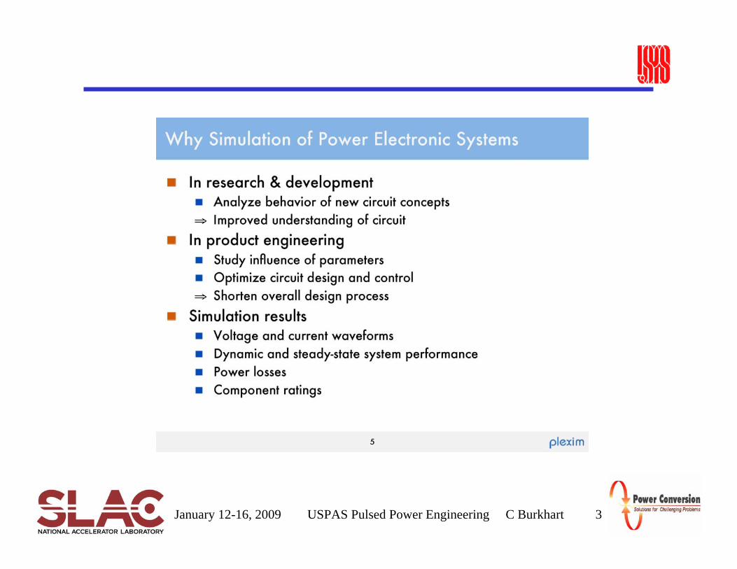
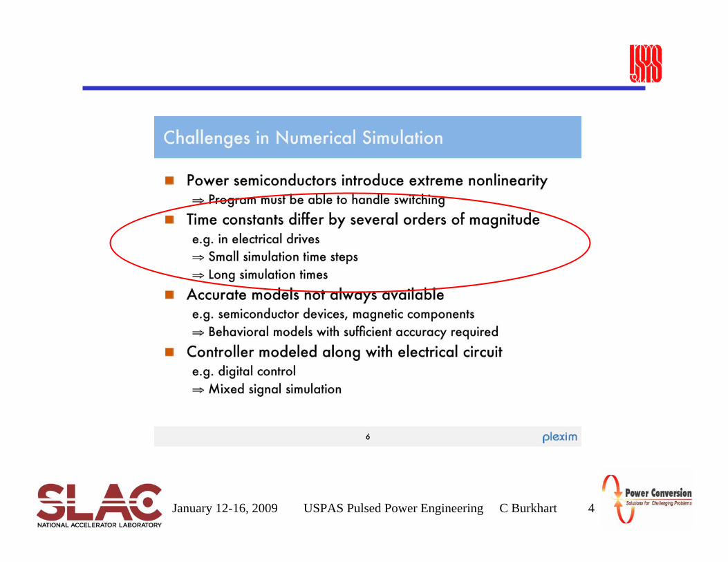
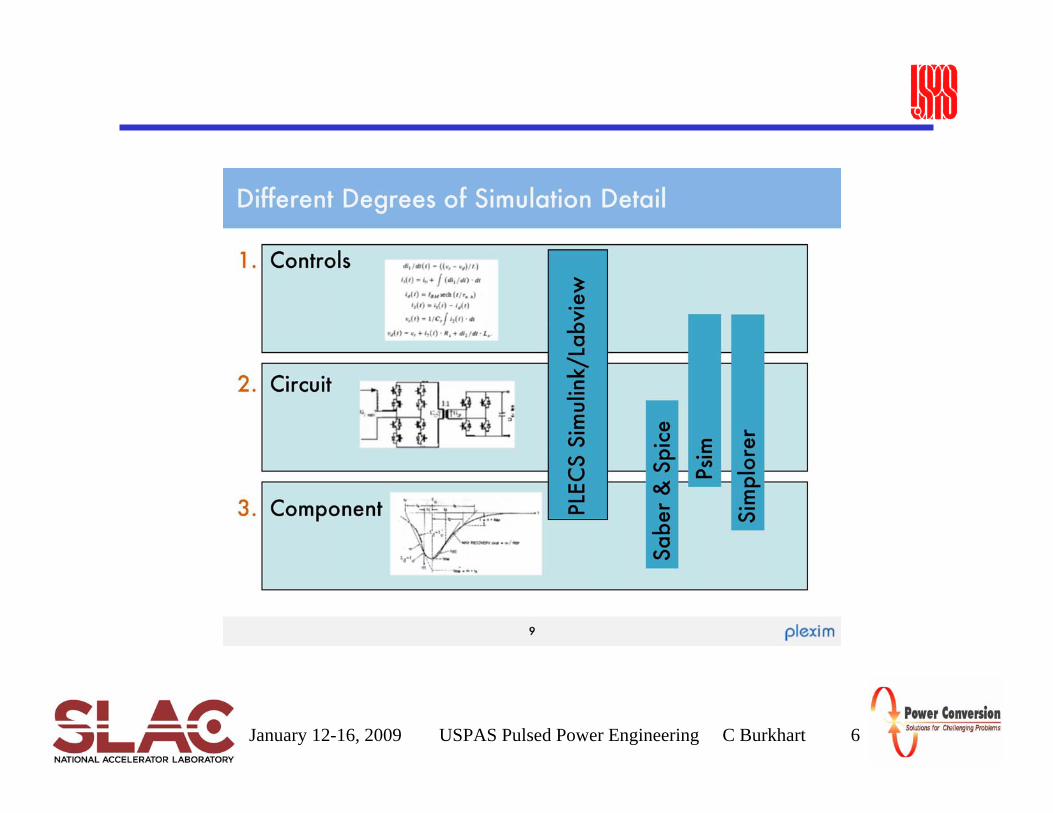
Circuit Simulation for Pulsed Power Applications• Uses of circuit simulation• Tools• Limitations• Typical methodology
January 12-16, 2009 USPAS Pulsed Power Engineering C Burkhart 3
January 12-16, 2009 USPAS Pulsed Power Engineering C Burkhart 4

January 12-16, 2009 USPAS Pulsed Power Engineering C Burkhart 5
January 12-16, 2009 USPAS Pulsed Power Engineering C Burkhart 6

January 12-16, 2009 USPAS Pulsed Power Engineering C Burkhart 7
Circuit Simulation Tools• Reduces circuit to N algebraic equations with N unknowns and solve
– Implicit integration Methods– Newton’s method– Etc.
• Spice/PSpice (Simulation Program with Integrated Circuit Emphasis)– Ubiquitous circuit solver– Developed at UC Berkeley, first presented in 1973– P in PSpice stands for personal computer– Large parts library– Analog and digital circuits
• Matlab/Simulink/SimPowerSystems/PLECS– Matlab mathematical tool teamed with specialized toolboxes– Simulink/SimPowerSystems– PLECS– Developed primarily for power electronics

January 12-16, 2009 USPAS Pulsed Power Engineering C Burkhart 8
Circuit Simulation Tools• PSIM
– Developed for power electronics– Fast convergence– Matlab interface
• Simplorer– Developed for power electronics– Four modeling languages
• VHDL-AMS for analog-mixed-signal-design• Circuit Simulator for the simulation of power electronic circuits• Block diagram simulator for the simulation of controllers and similar tasks• State machine simulator for event driven systems
• Saber– Developed for a wide range of applications, including power electronics– Can handle analog, digital, mixed and event driven devices– Can be linked to digital simulations to handle models written in Verilog or VHDL– Very powerful/very expensive
• Bertha– SNL transmission line-based

January 12-16, 2009 USPAS Pulsed Power Engineering C Burkhart 9
Pulsed Power Circuit Simulation• Almost exclusively transient analysis• Tend to generate sparse, stiff matrices, challenging for convergence• Tips to improved convergence
– Simplify the model as much as possible• Replace semiconductors with ideal switches or initial conditions• Use generic and/or ideal components
– Insert resistance to ground from areas with convergence troubles– Avoid series elements (2 inductors → a single inductor if nothing else
connects to the node between)– Relax tolerances– Avoid small time steps– Slow down transitions (e.g. add RC snubber)

January 12-16, 2009 USPAS Pulsed Power Engineering M Kemp 10
Simulation Software Contents• Typically included in circuit simulation programs are complementary
packages.– Extensive part libraries for manufacturers– Optimization modules– PCB layout software– Specialized schematic tools– Advanced post-processing

January 12-16, 2009 USPAS Pulsed Power Engineering M Kemp 11
Typical Work Flow
• Circuit simulation programs vary with the specific steps to solve a problem, but many share similar steps
• First, simulation directories are created and a graphical schematic interface is opened.
• For Spice simulators, the graphical interface is simply a tool to easily generate Spice netlists.

January 12-16, 2009 USPAS Pulsed Power Engineering M Kemp 12
Typical Work Flow
• Shown is a simple pulsed power circuit. Also shown is the Spice netlist that was generated by the software.
• Initial conditions such as voltage on a capacitor and current through an inductor are input.
• For transient, AC bias, and DC bias simulations, measurement points are typically placed at areas of interest.
• Simulation parameters such as length of simulation, maximum time step, and convergence criteria are set

January 12-16, 2009 USPAS Pulsed Power Engineering M Kemp 13
Typical Work Flow
• Shown is the result in the post-processor. This example is the current through a resistor.
• Parameters such as rise-time, maximum, pulse-width, or rms value can be computed.

January 12-16, 2009 USPAS Pulsed Power Engineering M Kemp 14
Typical Work Flow
• Algebraic expressions using the simulated traces can be calculated
• In this example, the power through the resistor is calculated

January 12-16, 2009 USPAS Pulsed Power Engineering M Kemp 15
Parametric Study
• Parametric sweeps show the circuit response if one or more of the element values is swept through a range of magnitudes.
• In this example, the resistance value is swept.
January 12-16, 2009 USPAS Pulsed Power Engineering M Kemp 16
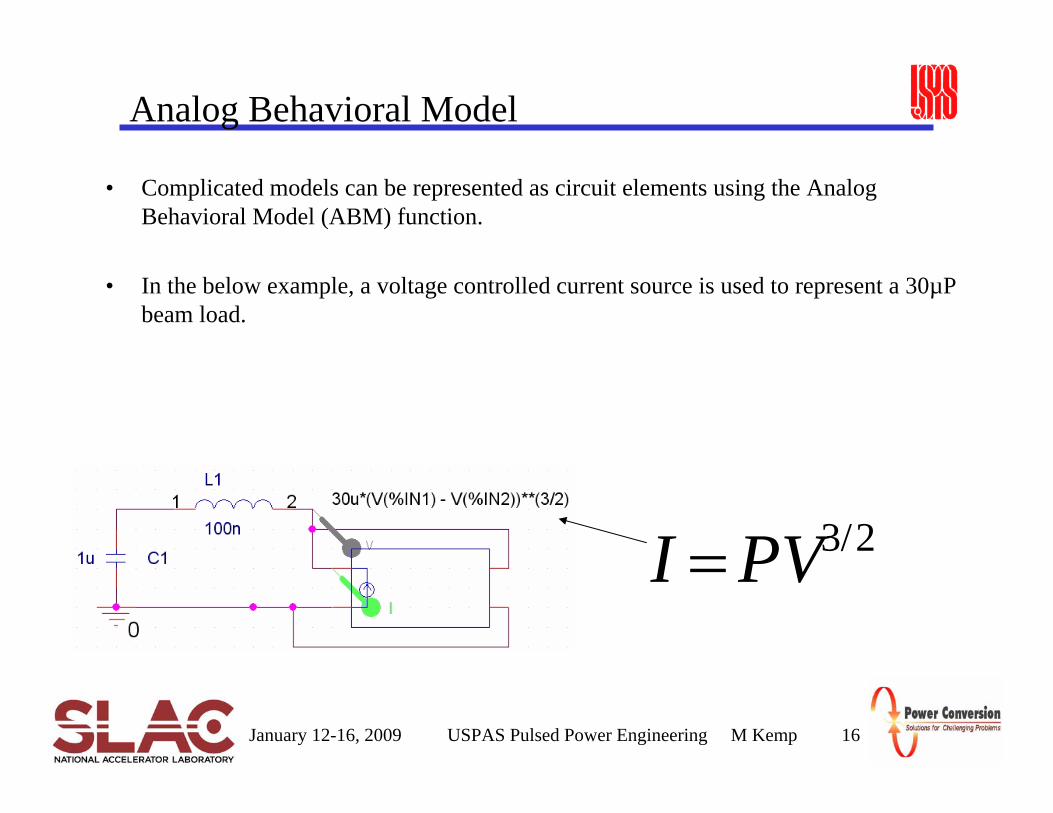
Analog Behavioral Model
• Complicated models can be represented as circuit elements using the Analog Behavioral Model (ABM) function.
• In the below example, a voltage controlled current source is used to represent a 30µP beam load.
2/3PVI =
January 12-16, 2009 USPAS Pulsed Power Engineering M Kemp 17
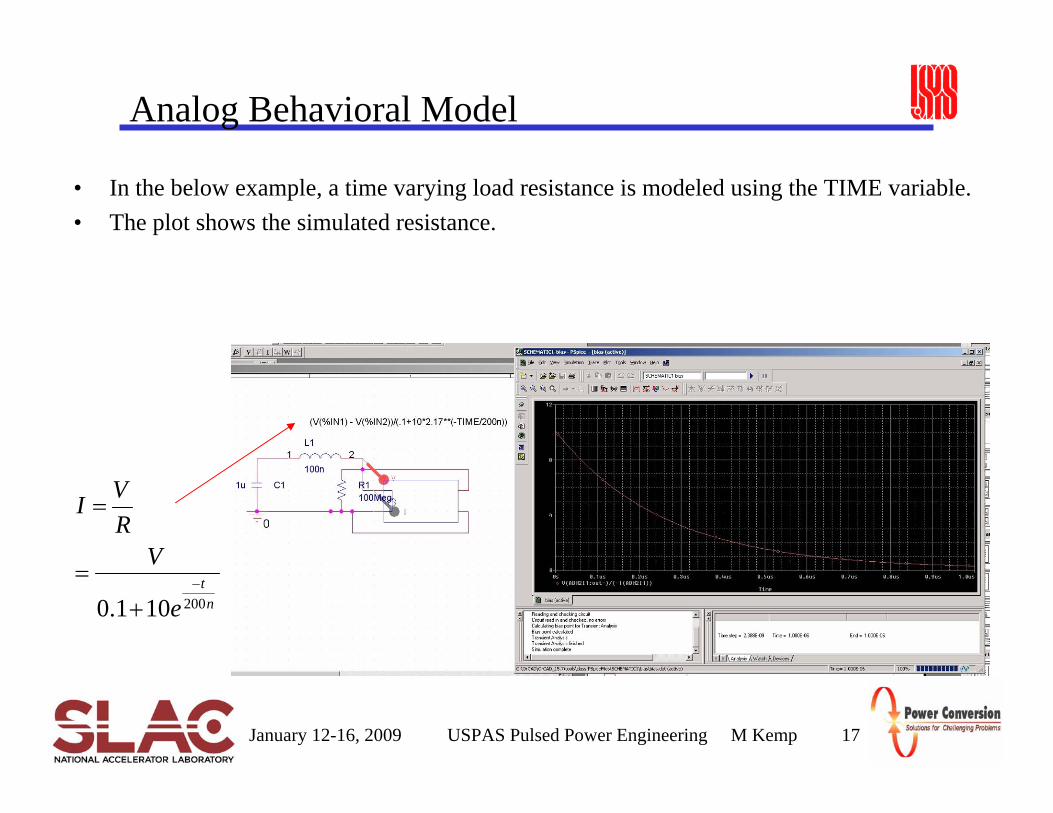
Analog Behavioral Model
• In the below example, a time varying load resistance is modeled using the TIME variable.• The plot shows the simulated resistance.
nt
e
VRVI
200101.0−
+=
=