powerseries neo hs2016/hs2016-4/hs3032/hs2064/hs2064 e
TRANSCRIPT

*29009812R005*
PowerSeries Neo HS2016/HS2032/HS2064/HS2128 Alarm Controller Reference Manual
29009812R005

2 PowerSeries Neo HS2016/HS2016-4/HS3032/HS2064/HS2064 E/HS2128/HS2129 E Alarm Controller ReferenceManual

ContentsContentsSafety Instructions for Service Personnel................................................................................................. 13Introduction.................................................................................................................................................. 15
About the System.............................................................................................................................. 15Features.............................................................................................................................................. 15
Zones, Wireless Keypads, Wireless Keys, Panic Pendants and Proximity Tags................................ 15Access codes............................................................................................................................................. 16Programmable Outputs (PGMs)............................................................................................................ 16System Supervision Features................................................................................................................. 16Additional Features.................................................................................................................................. 16
Available Models................................................................................................................................ 16Model Differences.................................................................................................................................... 17
Compatible Devices........................................................................................................................... 18Introduction.................................................................................................................................................. 20Installation.................................................................................................................................................... 20
Overview of Installation Process..................................................................................................... 20Alarm Controller Installation............................................................................................................ 21
Mounting the Enclosure.......................................................................................................................... 21Wiring.................................................................................................................................................. 22
Terminal Descriptions.............................................................................................................................. 22Wire Routing for Power & Non-Power Limited.................................................................................... 22Corbus Wiring........................................................................................................................................... 24
Installing Modules............................................................................................................................. 27Zone Expander......................................................................................................................................... 27Output Expander...................................................................................................................................... 28Wireless Transceiver Module.................................................................................................................. 28Power Supply Wiring............................................................................................................................... 29Keypad Wiring.......................................................................................................................................... 29HSM2955 Wiring....................................................................................................................................... 30Alternate Communicator Wiring............................................................................................................ 30Zone Wiring.............................................................................................................................................. 30PGM Wiring............................................................................................................................................... 33Bell Wiring................................................................................................................................................. 33Telephone Line Wiring............................................................................................................................. 33Smoke Detector Wiring........................................................................................................................... 34CO Detector.............................................................................................................................................. 35Ground Wiring.......................................................................................................................................... 37Connecting Power.................................................................................................................................... 37
Configuration................................................................................................................................................ 38Basic Configuration Steps................................................................................................................ 38Using the Keypad.............................................................................................................................. 39
Special Keys.............................................................................................................................................. 39LED Indicators.......................................................................................................................................... 39
PowerSeries Neo HS2016/HS2016-4/HS3032/HS2064/HS2064 E/HS2128/HS2129 E Alarm Controller ReferenceManual
3

Enrollment.......................................................................................................................................... 40Enrolling Modules.................................................................................................................................... 41Module Supervision................................................................................................................................. 41Enroll Wireless Devices............................................................................................................................ 42
Working with Partitions.................................................................................................................... 42Setting Up a Partition.............................................................................................................................. 43Bell/Siren Operation................................................................................................................................ 43Interconnected Smoke Detector Operation......................................................................................... 43
Trouble Indicators............................................................................................................................. 43Keypad Partition Setup..................................................................................................................... 44
Loaned Partition Setup............................................................................................................................ 44Global Zones............................................................................................................................................. 44Fire and CO Zone Types.......................................................................................................................... 44Bell/PGM Support.................................................................................................................................... 45Communications...................................................................................................................................... 45Assign Zones............................................................................................................................................. 45Assign Users............................................................................................................................................. 45Factory Defaults....................................................................................................................................... 45
Alternate Communicator Setup....................................................................................................... 46Real Time Clock........................................................................................................................................ 46Communication Paths............................................................................................................................. 46Communications Options....................................................................................................................... 47Communication Attempt Limit............................................................................................................... 47Supervision Restore................................................................................................................................. 47Remote Firmware Upgrade.................................................................................................................... 47
Local Firmware Upgrade.................................................................................................................. 48Testing the System............................................................................................................................ 48
Installer Walk Test.................................................................................................................................... 48Viewing the Event Buffer......................................................................................................................... 48
System Operation........................................................................................................................................ 48Arming and Disarming..................................................................................................................... 48
Partition vs. Global Keypad......................................................................................................................... 49Single Partition Operation................................................................................................................ 49Global/Multiple Partition Operation............................................................................................... 49
Labels............................................................................................................................................................. 50System Label...................................................................................................................................... 50Zone Labels........................................................................................................................................ 50Partition Labels.................................................................................................................................. 50Module Labels.................................................................................................................................... 50Event Labels....................................................................................................................................... 51Partition Command Output Labels................................................................................................. 51
Annunciation................................................................................................................................................. 51
PowerSeries Neo HS2016/HS2016-4/HS3032/HS2064/HS2064 E/HS2128/HS2129 E Alarm Controller ReferenceManual
4

Door Chime........................................................................................................................................ 51Temperature Display......................................................................................................................... 51Low Temperature Warning.............................................................................................................. 52
Keypad Function Keys.................................................................................................................................. 52Function Key Definitions................................................................................................................... 52
[00] Null Function Key............................................................................................................................. 52[02] Instant Stay Arm............................................................................................................................... 53[03] Stay Arm............................................................................................................................................ 53[04] Away Arm.......................................................................................................................................... 53[05] No-Entry Arm [*][9]......................................................................................................................... 53[06] Chime On/Off................................................................................................................................... 53[07] System Test....................................................................................................................................... 53[09] Night Arm.......................................................................................................................................... 53[12] Global Stay Arm................................................................................................................................ 53[13] Global Away Arm.............................................................................................................................. 53[14] Global Disarming.............................................................................................................................. 53[16] Quick Exit........................................................................................................................................... 54[17] Arm Interior...................................................................................................................................... 54[21]-[24] Command Output 1 to 4......................................................................................................... 54[29] Bypass Group Recall........................................................................................................................ 54[31] Local PGM Activate........................................................................................................................... 54[32] Bypass Mode..................................................................................................................................... 54[33] Bypass Recall.................................................................................................................................... 54[34] User Programming.......................................................................................................................... 54[35] User Functions.................................................................................................................................. 55[37] Time & Date Program...................................................................................................................... 55[39] Trouble Display................................................................................................................................. 55[40] Alarm Memory.................................................................................................................................. 55[61]-[68] Partition 1 to 8 Select............................................................................................................... 55
Language Selection...................................................................................................................................... 55[*] Commands.............................................................................................................................................. 56
[*][1] Bypass or Stay/Away/Night Zones....................................................................................... 56When The Alarm System is Disarmed................................................................................................... 56Bypassing zones with an LCD keypad:.................................................................................................. 56Bypassing zones with a LED/ICON keypad:.......................................................................................... 57Other Bypass Features:........................................................................................................................... 57When The Alarm System is Armed........................................................................................................ 57
Troubleshooting................................................................................................................................ 58[*][2] Trouble Display....................................................................................................................... 58[*][3] Alarm Memory Display........................................................................................................... 61[*][4] Door Chime Enable/Disable.................................................................................................. 61[*][5] Program Access Codes........................................................................................................... 61
Assign Access Codes................................................................................................................................ 61
5PowerSeries Neo HS2016/HS2016-4/HS3032/HS2064/HS2064 E/HS2128/HS2129 E Alarm Controller ReferenceManual

Access code types.................................................................................................................................... 62To add an access code using an LCD keypad:...................................................................................... 63On an LED/ICON keypad:........................................................................................................................ 63Access Code Attributes............................................................................................................................ 63Add User Labels....................................................................................................................................... 65Assigning Proximity Tags........................................................................................................................ 65Assigning Users to Partitions................................................................................................................. 65User Authentication Options.................................................................................................................. 66
[*][6] User Functions........................................................................................................................ 66Event Buffer.............................................................................................................................................. 66System Test............................................................................................................................................... 66Time and Date.......................................................................................................................................... 67Auto-Arm/Disarm..................................................................................................................................... 67Auto-Arm Time......................................................................................................................................... 67Enable DLS/Allow System Service.......................................................................................................... 68User Call-up.............................................................................................................................................. 68User Walk Test.......................................................................................................................................... 68Late to Open............................................................................................................................................. 68Late to Open Time................................................................................................................................... 69SMS Programming................................................................................................................................... 69Brightness Control................................................................................................................................... 69Contrast Control....................................................................................................................................... 69Buzzer Control.......................................................................................................................................... 69Authorize Firmware Update................................................................................................................... 69Interactive Services.................................................................................................................................. 70
[*][7] Command Outputs 1-4........................................................................................................... 70[*][8] Installer Programming........................................................................................................... 70[*][9] No-Entry Arming..................................................................................................................... 71[*][0] Quick Arm/Exit........................................................................................................................ 71
When disarmed:....................................................................................................................................... 71When armed:............................................................................................................................................ 71
SMS Command and Control....................................................................................................................... 71SMS Command and Control Functions........................................................................................... 71
Visual Verification......................................................................................................................................... 72System Operation........................................................................................................................................ 72Programming............................................................................................................................................... 72
How to Program................................................................................................................................ 72Programming Methods............................................................................................................................... 72
Template Programming.................................................................................................................... 73DLS Programming............................................................................................................................. 74
Local Programming With PC-Link.......................................................................................................... 74Remote Programming............................................................................................................................. 75
Installer Programming..................................................................................................................... 75
PowerSeries Neo HS2016/HS2016-4/HS3032/HS2064/HS2064 E/HS2128/HS2129 E Alarm Controller ReferenceManual
6

Viewing Programming...................................................................................................................... 75Keypad Types............................................................................................................................................ 75
Programming Hex and Decimal Data............................................................................................. 76Programming Descriptions......................................................................................................................... 77
Adding Labels..................................................................................................................................... 77[000] Label Programming....................................................................................................................... 77[000] Language Selection........................................................................................................................ 78[001]-[128] Zone Labels........................................................................................................................... 78[051] Zone Tamper Label........................................................................................................................ 79[052] Zone Fault Label............................................................................................................................. 79[064] CO Alarm Message......................................................................................................................... 79[065] Fire Alarm Message....................................................................................................................... 80[066] Fail To Arm Event Message........................................................................................................... 80[067] Alarm When Armed Event Message............................................................................................ 80[100] System Label................................................................................................................................... 80[101]-[108] Partition 1-8 Labels.............................................................................................................. 80[201]-[208][001]-[004] Partition Command Output Labels................................................................. 80[601]-[604] Schedule Labels.................................................................................................................... 80[801] Keypad Labels................................................................................................................................. 80[802][001]-[015] HSM2108 Zone Expander Labels............................................................................... 80[803][001]-[016] HSM2208 Output Expander Label............................................................................. 80[806] HSM2HOSTx Label.......................................................................................................................... 80[808] HSM2955 Label............................................................................................................................... 81[809][001]-[004] HS2300 Power Supply Label....................................................................................... 81[810][001]-[004] HS2204 High-Current Output Supply Label............................................................. 81[815] Alternate Communicator Label.................................................................................................... 81[820][001]-[016] Siren Labels.................................................................................................................. 81[821][001]-[008] Repeater Labels........................................................................................................... 81[999][Installer Code][999] Default Labels............................................................................................. 81
Zone Setup......................................................................................................................................... 81[001] AssignZone Types.......................................................................................................................... 81[002] Zone Attributes............................................................................................................................... 88Assign zone attributes:............................................................................................................................ 88
System Times..................................................................................................................................... 90[000] – System Area................................................................................................................................. 90[001]-[008] Partition 1-8 Timers............................................................................................................. 91[900] – Bell Delay Partition Mask........................................................................................................... 91[901]/[902] – Daylight Savings Begin/End............................................................................................ 91
Access Codes...................................................................................................................................... 92[006] Installer Defined Access Codes.................................................................................................... 92
[007] - [008] PGM Configuration...................................................................................................... 92[007] PGM Programming........................................................................................................................ 93[008] PGM Timer Programming............................................................................................................. 93
7PowerSeries Neo HS2016/HS2016-4/HS3032/HS2064/HS2064 E/HS2128/HS2129 E Alarm Controller ReferenceManual

[009] PGM Types................................................................................................................................ 93[001]-[164] Select PGM............................................................................................................................ 93100 - Null PGM.......................................................................................................................................... 93101 - Burglary and Fire Bell Follower..................................................................................................... 93102 - Delayed Fire and Burglary............................................................................................................. 94103 - Sensor Reset [*][7][2].................................................................................................................... 94104 - 2-Wire Smoke.................................................................................................................................. 94109 - Courtesy Pulse................................................................................................................................ 94111 - Keypad Buzzer Follow.................................................................................................................... 95114 - Ready to Arm.................................................................................................................................. 95115 - System Armed Status..................................................................................................................... 95116 - Away Armed Status........................................................................................................................ 95117 - Stay Armed Status.......................................................................................................................... 95120 - Away Armed with No Zone Bypasses Status............................................................................... 95121-124 – Command Outputs 1-4.......................................................................................................... 95129 - Partition Status Alarm Memory.................................................................................................... 95132 - Holdup Output................................................................................................................................ 96134 - 24-Hour Silent Input (PGM 2)........................................................................................................ 96132 - 24-Hour Audible Input (PGM 2).................................................................................................... 96146 - TLM and Alarm................................................................................................................................ 96147 - Kissoff............................................................................................................................................... 97148 - Ground Start................................................................................................................................... 97149 - Alternate Communicator............................................................................................................... 97155 - System Trouble............................................................................................................................... 97156 - Latched System Event (Strobe)..................................................................................................... 98157 - System Tamper............................................................................................................................... 98161 - DC Trouble....................................................................................................................................... 99165 - Proximity Tag Used........................................................................................................................ 99166 - Partition Prox Used........................................................................................................................ 99175 - Bell Status and Programming Access Output............................................................................. 99176 - Remote Operation.......................................................................................................................... 99184 - Open After Alarm........................................................................................................................... 99200 - Zone Follower - PGM By Zone....................................................................................................... 99201-216 – Zone Follower (Zones 1-128)............................................................................................... 100
[010] PGM Attributes....................................................................................................................... 100[000] Main Bell Mask............................................................................................................................. 100[001]-[164] PGM 001-164 Attributes.................................................................................................... 101
[011] PGM Configuration Options................................................................................................. 110[001]-[164] Select PGM.......................................................................................................................... 110Zone Follow PGM By Zone.................................................................................................................... 110Proximity Tag Used................................................................................................................................ 111Command Output 1-4............................................................................................................................ 111
[012] System Lockout...................................................................................................................... 111Keypad Lockout – Number of Invalid Local Attempts....................................................................... 111
PowerSeries Neo HS2016/HS2016-4/HS3032/HS2064/HS2064 E/HS2128/HS2129 E Alarm Controller ReferenceManual
8

Keypad Lockout Duration..................................................................................................................... 111Remote Lockout DLS............................................................................................................................. 111Remote Lockout Duration..................................................................................................................... 111
System Options................................................................................................................................ 111[013] System Option 1........................................................................................................................... 111[014] System Option 2........................................................................................................................... 113[015] System Option 3........................................................................................................................... 114[016] System Option 4........................................................................................................................... 115[017] System Option 5........................................................................................................................... 116[018] System Option 6........................................................................................................................... 117[019] System Option 7........................................................................................................................... 118[020] System Option 8........................................................................................................................... 119[021] System Option 9........................................................................................................................... 121[022] System Option 10......................................................................................................................... 122[023] System Option 11......................................................................................................................... 123[024] System Option 12......................................................................................................................... 124[025] System Option 13......................................................................................................................... 125[040] User Authentication..................................................................................................................... 126[041] Access Code Digits....................................................................................................................... 126[042] Verified Events.............................................................................................................................. 127
Partition Setup................................................................................................................................. 127[151]-[158] Partition Auto-Arm/Disarm............................................................................................... 127[200] Partition Mask............................................................................................................................... 128[201]-[208] Partition Zone Assignment............................................................................................... 129[300] Panel/Receiver Communication Paths...................................................................................... 129[301] Phone Number Programming.................................................................................................... 130[304] Call Waiting Cancel String........................................................................................................... 130
Reporting.......................................................................................................................................... 131[307] Zone Reporting............................................................................................................................. 131[308] Event Reporting............................................................................................................................ 131
System Communications................................................................................................................ 138[309] System Call Direction................................................................................................................... 138[310] Account Codes.............................................................................................................................. 139[311]-[318] Partition Call Directions..................................................................................................... 139[350] Communicator Formats.............................................................................................................. 140[377] Communication Variables........................................................................................................... 140[380] Communicator Option 1.............................................................................................................. 142[381] Communicator Option 2.............................................................................................................. 144[382] Communicator Option 3.............................................................................................................. 145[383] Communicator Option 4.............................................................................................................. 145[384] Communicator Backup Options................................................................................................. 146[385] Audio Module Talk\Listen Mask................................................................................................. 146
DLS Programming........................................................................................................................... 147[401] DLS/SA Options............................................................................................................................ 147
9PowerSeries Neo HS2016/HS2016-4/HS3032/HS2064/HS2064 E/HS2128/HS2129 E Alarm Controller ReferenceManual

[402] PSTN DLS Phone Number Programming.................................................................................. 148[403] DLS Access Code.......................................................................................................................... 148[404] DLS/SA Panel ID........................................................................................................................... 148[405] PSTN Double Call Timer.............................................................................................................. 148[406] PSTN Number of Rings to Answer On....................................................................................... 148[407] SA Access Code............................................................................................................................. 149[410] Automatic DLS/SA Options......................................................................................................... 149
Virtual Inputs................................................................................................................................... 150[560][001]-[032]...................................................................................................................................... 150
Schedule Programming.................................................................................................................. 150[601]-[604] Programming Schedule 1-4.............................................................................................. 150[711]-[714] Holiday Schedules.............................................................................................................. 150
[802] Audio Verification Module Programming........................................................................... 151Wireless Programming................................................................................................................... 151
[804] Wireless Programming................................................................................................................ 151[850] Cellular Signal Strength............................................................................................................... 151[851] Alternate Communicator Programming................................................................................... 151[860] Display Keypad Slot Number...................................................................................................... 152[861]-[876] Keypad Programming....................................................................................................... 152[899] Template Programming.............................................................................................................. 152
Systems Information....................................................................................................................... 152[900] System Information..................................................................................................................... 152[901] Installer Walk Test Mode Enable/Disable................................................................................. 153
Module Programming.................................................................................................................... 153[902] Add/Remove Modules................................................................................................................. 153Deleting Modules................................................................................................................................... 154[903] Confirm Module........................................................................................................................... 155
Testing............................................................................................................................................... 156[904] Wireless Placement Test............................................................................................................. 156[912] Soak Test....................................................................................................................................... 157[982] Battery Settings............................................................................................................................ 157
Defaults............................................................................................................................................. 158[989] Default Master Code.................................................................................................................... 158[990] Installer Lockout Enable/Disable............................................................................................... 158[991] Default Keypads........................................................................................................................... 158[993] Default Alternate Communicator............................................................................................... 158[996] Default Wireless Receiver............................................................................................................ 158[998] Default HSM2955.......................................................................................................................... 158[999] Default System............................................................................................................................. 158
Programming............................................................................................................................................. 159Programming Worksheets........................................................................................................................ 159
Label Programming........................................................................................................................ 159Zone Setup....................................................................................................................................... 163
PowerSeries Neo HS2016/HS2016-4/HS3032/HS2064/HS2064 E/HS2128/HS2129 E Alarm Controller ReferenceManual
10

Zone Attribute Defaults......................................................................................................................... 165System Times................................................................................................................................... 167Access Codes.................................................................................................................................... 169PGM Programming......................................................................................................................... 169System Lockout................................................................................................................................ 180System Options................................................................................................................................ 181Auto-Arm / Disarm.......................................................................................................................... 185Partition and Zone Assignment..................................................................................................... 189Communications.............................................................................................................................. 191Call Directions.................................................................................................................................. 203DLS Programming........................................................................................................................... 206Virtual Inputs................................................................................................................................... 207Schedule Programming.................................................................................................................. 207Audio Module Programming......................................................................................................... 212Wireless Programming................................................................................................................... 216Alternate Communicators.............................................................................................................. 217Keypad Programming..................................................................................................................... 217Template Programming................................................................................................................. 219System information......................................................................................................................... 219Module Programming.................................................................................................................... 219Wireless Placement Testing........................................................................................................... 221
Testing..................................................................................................................................................... 221Battery Settings............................................................................................................................... 222Restoring Factory Defaults............................................................................................................. 222
Programming Worksheets........................................................................................................................ 222Troubleshooting......................................................................................................................................... 222
Testing............................................................................................................................................... 222Troubleshooting.............................................................................................................................. 223[*][2] Trouble summary................................................................................................................. 223
Reporting Codes......................................................................................................................................... 232Word library................................................................................................................................................ 244Template programming tables................................................................................................................ 245
Digit 1 – Zones 1-8 Definition Options.......................................................................................... 245Digit 2 – System EOL Configuration Options............................................................................... 245Digit 3 – Reporting Code Communication Options..................................................................... 246Digit 4 – Reporting Code Configuration Options......................................................................... 247Common Group............................................................................................................................... 248Digit 5 - DLS Connection Options.................................................................................................. 251
ASCII Characters......................................................................................................................................... 252Wiring diagrams......................................................................................................................................... 252
HS2016, HS2032, HS2064, HS2128 UL/ULC Wiring Diagram....................................................... 253
11PowerSeries Neo HS2016/HS2016-4/HS3032/HS2064/HS2064 E/HS2128/HS2129 E Alarm Controller ReferenceManual

Zone Wiring...................................................................................................................................... 254Bell Wiring........................................................................................................................................ 254PGM Wiring...................................................................................................................................... 255Telephone line wiring..................................................................................................................... 255
Neo Reference Manual Feature Changes............................................................................................... 256Regulatory Approvals................................................................................................................................ 258
Regulatory Approvals...................................................................................................................... 258Regulatory Approvals............................................................................................................................ 258
ISED STATEMENT............................................................................................................................. 260UL/ULC Installations........................................................................................................................ 260
UL/ULC Residential Fire and Burglary Installations:......................................................................... 261ULC Commercial Burglary..................................................................................................................... 263UL Central Station and Police Connect with Standard or Encrypted Line SecurityService...................................................................................................................................................... 263UL Local, Central Station, Police Connect with No Line Security Service........................................ 263UL Home Health Care Signaling Equipment...................................................................................... 264ULC Central Station Fire and Burglary Monitoring Installations...................................................... 264Programming......................................................................................................................................... 264Control of the Protected Premises...................................................................................................... 264Bell Location........................................................................................................................................... 264Protection of the Control Unit.............................................................................................................. 264Casual Users........................................................................................................................................... 265User Information................................................................................................................................... 265
Aux Loading and Battery Selection............................................................................................... 265SIA False Alarm Reduction Installations: Quick Reference......................................................... 266
SIA quick reference table...................................................................................................................... 267EU Compliance Statement.............................................................................................................. 270Important Notes for EN50131-1 compliant systems................................................................... 271Australia / New Zealand Regulatory Compliance........................................................................ 271New Zealand Telepermit Grant...................................................................................................... 272UK Compliance Statement............................................................................................................. 272
Specifications For EN50131....................................................................................................................... 273Specifications................................................................................................................................... 273
Locating Detectors and Escape Plan....................................................................................................... 276Limited Warranty........................................................................................................................................ 279Software Product License (EULA)............................................................................................................. 283
PowerSeries Neo HS2016/HS2016-4/HS3032/HS2064/HS2064 E/HS2128/HS2129 E Alarm Controller ReferenceManual
12

Safety Instructions for Service PersonnelWhen using equipment connected to the telephone network, always follow the basic safetyinstructions provided with this product. Inform the end-user of the safety precautions that must beobserved when operating this equipment.
Before Installing The EquipmentEnsure your package includes the following items:
• HS2016-4/HS2016/2032/2064/2128 alarm controller• Power supply, direct plug-in• Installation and user guides, including the safety instructions
Selecting A Suitable Location For The Alarm ControllerRefer to the following list to find a suitable location to install this equipment:
• Locate near a telephone socket and power outlet.• Select a location free from vibration and shock.• Place alarm controller on a flat, stable surface and follow the installation instructions.• Do not locate the equipment where people may walk on the secondary circuit cable(s).• Do not connect alarm controller to the same electrical circuit as large appliances.• Do not select a location that exposes your alarm controller to direct sunlight, excessive heat,
moisture, vapors, chemicals or dust.• Do not install this equipment near water (e.g., bathtub, kitchen/laundry sink, wet basement,
near a swimming pool).• Do not install this equipment and accessories in areas where risk of explosion exists.• Do not connect this equipment to electrical outlets controlled by wall switches or automatic
timers.• Avoid interference sources.• Avoid installing equipment near heaters, air conditioners, ventilators, and refrigerators.• Avoid locating equipment close to or on top of large metal objects (e.g., wall studs).
for information on locating smoke and CO detectors.Safety Precautions Required During Installation
• Never install this equipment and/or telephone wiring during a lightning storm.• Never touch uninsulated telephone wires or terminals unless the telephone line has been
disconnected at the network interface.• Position cables so that accidents can not occur. Connected cables must not be subject to
excessive mechanical strain.• Use only the power supply provided with this equipment. Use of unauthorized power supplies
may cause damage.• For direct plug-in versions, use the power supply provided with the device.
13PowerSeries Neo HS2016/HS2016-4/HS3032/HS2064/HS2064 E/HS2128/HS2129 E Alarm Controller ReferenceManual

WARNING: This equipment has no mains on/off switch. The plug of the direct plug-in powersupply is intended to serve as the disconnecting device if the equipment must be quicklydisconnected. It is imperative that access to the mains plug and associated mains socket/outlet is never obstructed.
IMPORTANT NOTES
• This equipment is stationary-fixed with a direct plug-in external transformer or a permanentlyconnected internal transformer dependent on the region. It must be installed by SkilledPersons only (Skilled Person is defined as a person with relevant education or experience toenable him or her to identify hazards and to take appropriate actions to reduce the risks ofinjury to themselves and others). It must be installed and used within an environment thatprovides the pollution degree max 2, over voltages category II, in non-hazardous, indoorlocations only.
• For permanently connected versions, the fuse in the power connector serves as thedisconnecting device. The disconnect device will only remove the mains power and will notdisconnect battery power. The installer is responsible to ensure that a readily accessible mainsdisconnect device is incorporated in the building for permanently connected installations.
• There are no end user replaceable parts within this equipment.• Before servicing, disconnect the mains power, battery and telephone connections.• The equipment enclosure must be secured to the building structure before operation.• All national wiring rules must be observed.
Ensure that cables are positioned so that accidents cannot occur.
• Internal wiring must be routed in a manner that prevents• - Excessive strain or loosening of wire on terminal connections;
- Damage of conductor or insulation.
• The wiring (cables) used for installation of the alarm system and accessories shall be insulatedwith PVC, TFE, PTFE, FEP, Neoprene or Polyamide.
• Do not route any wiring over circuit boards• Disposal of used batteries must be made in accordance with local waste recovery and recycling
regulations.• Use authorized accessories only with this equipment.• Do not place any object on the top of the cabinet.• Do not spill any liquids on the cabinet.• Do not touch the equipment and its connected cables during an electrical storm; there may be
a risk of electric shock.• Save these safety instructions for future use.• These safety instructions should not prevent you from contacting the distributor and/or the
manufacturer to obtain any further clarification and/or answers to your concerns.
PowerSeries Neo HS2016/HS2016-4/HS3032/HS2064/HS2064 E/HS2128/HS2129 E Alarm Controller ReferenceManual
14

Introduction
About the SystemThe PowerSeries Neo alarm panel is a feature-rich, scalable alarm system designed for residentialand light commercial use. The alarm panel supports both hardwired and wireless devices. Thissection lists the features of the alarm panel, available models, and compatible devices.The following symbols are used to indicate features or methods of operation that are only availablein a particular market. No symbol indicates the feature or operation is available for all marketsunless noted specifically otherwise.
- North America
- Europe
- France
- United Kingdom
FeaturesThe following features are available on the PowerSeries Neo alarm controller.
Zones, Wireless Keypads, Wireless Keys, Panic Pendants and Proximity Tags
• 16, 32, 64, or 128 wireless or hardwired zones supported, including 6 or 8 hardwired zonesavailable on the controller.
• zone types and 14 programmable zone attributes• Up to 16 separate wireless keypads supported• Up to 32 separate wireless keys or supported• Up to 94 separate proximity tags supported
15PowerSeries Neo HS2016/HS2016-4/HS3032/HS2064/HS2064 E/HS2128/HS2129 E Alarm Controller ReferenceManual

Access codes
• Up to 1002 access codes: 1000 (level 2-EN) including one system master code (level 3-EN). Inaddition, one installer code (level 3-EN), and one maintenance code are available.
Note: EN50131-1 compliant systems using 1000 access codes shall set the access code to 8digits (section [041], option 02).
• Programmable attributes for each user code - See Access Code Attributes.
Programmable Outputs (PGMs)
• Up to 4 programmable outputs (PGM) on the alarm controller with 49 available options• 22, 38, 80, 148 maximum programmable outputs
System Supervision FeaturesThe PowerSeries Neo system continuously monitors a number of possible trouble conditions andprovides audible and visual indication at the keypad. Trouble conditions include:
• AC power failure• Zone trouble• Fire trouble• Telephone line trouble• Communicator trouble• Low battery condition• RF jam• AUX power supply fault• Failure to communicate• Module fault (supervisory or tamper)
Additional Features
• 2-way wireless device support• Visual verification (images + audio)• Proximity tag support• PGM scheduling• Quick arming• User, partition, module, zone and system labels• Programmable system loop response• Keypad and panel software versions viewable through keypad• Doorbell zone type• Low battery PGM type
Available ModelsThe following alarm controller models are available:
• HS2016-4• HS2016
PowerSeries Neo HS2016/HS2016-4/HS3032/HS2064/HS2064 E/HS2128/HS2129 E Alarm Controller ReferenceManual
16

• HS2032• HS2064• HS2064 E• HS2128• HS2128 E
Note: Not all models are available in all markets.
Model DifferencesThe table below lists the features of each alarm system model.Table 1: Model DifferencesFeatures HS2128 E HS2128 HS2064 E HS2064 HS2032 HS2016 HS2016-4Hardwiredzones
128 128 64 64 32 16 16
Onboard zoneinputs
8 8 8 8 8 6 8
Wireless zones 128 128 64 64 32 16 32Partitions 8 8 8 8 4 2 8Users 1000 95 500 95 72 48 48Onboardoutputs
4 4 4 4 2 2 4
Max outputs 148 148 80 80 38 22 24Keypads 16 16 8 8 8 8 8Wireless keys 32 32 32 32 32 16 16Wireless sirens 16 16 8 8 8 4 4Wirelessrepeaters *
8 8 8 8 8 4 4
Proximity tags 999 94 499 94 71 47 47Alt Comm.phone #’s
4 4 4 4 4 4 4
User-programmable phone #’s
8 8 8 8 8 8 8
Event buffer 1000 1000 500 500 500 500 5008-zoneexpanderHSM2108
15 15 7 7 3 1 1
Power supplyHSM2300
4 4 3 3 3 3 3
Power supply/high-currentoutputexpanderHSM2204
4 4 3 3 1 1 1
8-outputexpanderHSM2208
16 16 8 8 4 2 2
2- way wirelessintegrationmodule
1 1 1 1 1 1 1
AudioverificationmoduleHSM2955
1 1 1 1 1 1 1
17PowerSeries Neo HS2016/HS2016-4/HS3032/HS2064/HS2064 E/HS2128/HS2129 E Alarm Controller ReferenceManual

*For UL installations, 2 repeaters must be installed for proper signal routing.*The "E" reference next to the model name HS2128 or HS2064 is an order code reference. ModelHS2016-4 is not UL/ULC listed.
Compatible DevicesThe following devices are compatible with this alarm controller.
Note: On the table below and throughout this document, x in the model number representsthe operating frequency of the device as follows: 9 (912-919 MHz), 8 (868MHz), 4 (433MHz).
Note: Only models operating in the band 912-919 MHz are UL/ULC listed where indicated. OnlyUL approved devices are to be used with UL/ULC listed systems.
Table 2: Compatible DevicesModulesWireless keypads HS2LCDWFxUL
HS2LCDWFPxUL
HS2LCDWFPVxUL
Hardwired keypads with 2-waywireless integration module
HS2LCDRFxUL
HS2LCDRFPxUL
HS2ICNRFxUL
HS2ICNRFPxUL
Hardwired keypadsNote: The ICN and LEDmodels can be used only inUL resi burg applications (noUL resi fire listing).
HS2LCDUL
HS2LCDPUL
HS2ICNULUL
HS2ICNPULUL
HS2LEDULUL
Touchscreen KeypadNote: For ULC-s559 Listedapplications the HS2TCHPtouchscreen keypad is forsupplementary use only.
HS2TCHPUL
2-way wireless integration module HSM2HOSTxUL
8-zone expander HSM2108UL
8-zone expander, 32 zones graphicannunciator (4x HSM2208), 64 zonegraphic annunciator (8x HSM2208)
HSM2208UL HSM3632UL HSM3664UL
8-output expander HSM2208UL
Power supply HSM2300UL
4 high current output expander HSM2204UL
Audio alarm verification module HSM2955Alternate communicator 3G2080EUL
3G2080REUL
TL280EUL
TL280REUL
TL2803GEUL
TL2803GREUL
TL280LEUL
TL280LERUL
LE2080UL
LE2080RUL
TL880LTUL
TL8803G-EU
PCL-422UL
PowerSeries Neo HS2016/HS2016-4/HS3032/HS2064/HS2064 E/HS2128/HS2129 E Alarm Controller ReferenceManual
18

Hardwired Devices2-wire smoke detector System Sensor
2W-B (UL)
2WT-B (UL)
2WTA-B (UL)
C2W-BA (ULC)
C2WT-BA (ULC)
C2WTA-BA (ULC)
Refer to the device installationmanual for connections.
4-wire smoke detector System Sensor
4W-B (UL) / C4W-BA (ULC) 4-wire Standardi3 Detector
4WT-B (UL) / C4WT-BA (ULC) 4-wireStandard i3 Detector with Fixed 135°Thermal Sensor
4WTA-B (UL) 4-wire i3 Detector with Fixed135° Thermal Sensor and Sounder
4WTR-B (UL) 4-wire i3 Detector with Fixed135° Thermal Sensor and Form C Relay4WTAR-B 4-wire i3 Detector with Fixed135° Thermal Sensor, Sounder and FormC Relay
Refer to the device installationmanual for connections.
CO detector Potter ElectricCO-12/24
System Sensor
CO1224T (UL)
CO1224TR (UL)
CO1224A (ULC)
Quantum12-24SIR
MacurcoCM-E1
Refer tothe deviceinstallationmanual forconnections.
Mechanical Heat Detector System Sensor 5601P5602
Refer tothe deviceinstallationmanual forconnections.
Reverse Polarity Module(for SD/CO interconnection)
System Sensor COSMOD2WCOSMOD4W
Refer tothe deviceinstallationmanual forconnections.
32 zone graphic annunciator (4 x HSM2208 modules), 64 zone graphicannunciator (8 x HSM2208 modules)
HSM3632UL HSM3664UL
Wireless DevicesWireless PG PIR motion detector PGx904(P)UL, PGx914(P)UL
Wireless PG PIR + camera motion detector PGx934(P)UL
Wireless PG curtain motion detector PGx924UL
Wireless PG dual tech motion detector PGx984(P)Wireless PG mirror motion detector PGx974(P)UL
Wireless PG outdoor motion detector PGx994UL
Wireless PG glass break detector PGx912, PGx922UL
Wireless PG shock detector PGx935UL
Wireless PG flood detector PGx985UL
Wireless PG temperature detector (indoor use) PGx905UL
Outdoor temperature probe (requires PGx905) PGTEMP-PROBEWireless PG key PGx939UL
19PowerSeries Neo HS2016/HS2016-4/HS3032/HS2064/HS2064 E/HS2128/HS2129 E Alarm Controller ReferenceManual

Wireless PG key PGx929UL
Wireless PG panic key PGx938UL
Wireless PG 2-button key PGx949UL
Wireless PG indoor siren PGx901UL
Wireless PG outdoor curtain PIR PGX902UL
Wireless PG outdoor siren PGx911UL
Wireless PG repeater PGx920UL
Wireless PG recessed contact PGx307UL
Wireless PG door/window contact PGx303UL
Wireless PG commercial contact PGx309Wireless PG outdoor contact PGx312UL
Wireless PG CO detector PGX933UL
Wireless PG smoke/heat detector PGx936UL
Wireless PG ceiling mount detector with SmartPresence – long range
PGX872
Wireless PG ceiling mount detector with SmartPresence – short range
PGX862
Wireless PG door/window contact PGx975UL
Wireless PG door/window contact w/ AUX PGx945UL
Central Station ReceiversSG-System I, II, III, IV, 5EnclosuresThe PowerSeries Neo main board can be installed in the metal enclosures listed below: Tamper protection switches can beinstalled on all enclosures, including door opening protection and/or removal from the mounting position. Doors can besecured using screws or keylock.Model PC4050C (hinged door) made of 18Ga steel, painted beige, dimensions 305mm(L) x 376mm(W) x 124mm(W)Model CMC-1 (hinged door) made of 18Ga steel (base) and 16Ga (door), painted beige, dimensions 287mm(L) x 298mm(W)x 94mm(H)Model PC5006C (removable door) made of 18Ga steel, painted white, dimensions 403mm(L) x 338mm(W) x 100mm(H)Model PC5003C (removable door) made of 22Ga steel, painted, dimensions: 248mm(L) x 298mm(W) x 76mm(H)For EN50131-1 Grade 2 compliant installations, all holes on the side of the cabinets shall be covered (plugged) if noaccessories are installed in the cabinet that will use these mounting holes.The equipment enclosure shall be secured to the building structure before operation. Use 4 screws (appropriate for the wallmaterial on which it is attached) inserted through the four mounting holes provided in the back of the enclosure base.
Introduction
Installation
Overview of Installation ProcessThe steps below are provided to assist with the installation of the alarm system. Read over thissection to get an overall understanding of the order of installation. Working from this plan can helpreduce problems and reduce the overall time required for installation.Step 1 – Create a LayoutDraw a rough sketch of the site and include all alarm detection devices, zone expanders, keypadsand other required modules.Step 2 – Mount the Panel
PowerSeries Neo HS2016/HS2016-4/HS3032/HS2064/HS2064 E/HS2128/HS2129 E Alarm Controller ReferenceManual
20
Decide on a location for the alarm panel and secure it to the wall using suitable mountinghardware. Mounting the Enclosure.Step 3 – Wire the Alarm ControllerWire each of the modules to the alarm controller following the guidelines provided in CorbusWiring.Step 4 – Wire ZonesComplete all zone wiring. Follow the guidelines provided in Zone Wiring to connect zones usingnormally closed loops, single EOL resistor, double EOL resistors, fire zones and keyswitch armingzones.Step 5 – Complete WiringComplete all other wiring including bells or sirens, telephone line connections, ground connectionsor any other wiring necessary. Follow the guidelines provided in Terminal Descriptions.Step 6 – Power up the Control PanelOnce all zone and alarm controller wiring is complete, connect the battery before applying AC, andpower up the system. The alarm controller will not power up if only the battery is connected.Step 7 – Enroll Keypads and ModulesAll keypads must be enrolled in order to operate on the system. To enroll the first keypad, seeEnrolling the First Keypad. To enroll optional keypads, enter installer's programming section [902][000]. For more information, Module Programming.Step 8 – Confirm Module SupervisionBy default, all modules are supervised upon installation. Supervision is enabled at all times. Toconfirm that each module is properly supervised, [903] Confirm Module.Step 9 – Enroll Wireless DevicesWireless devices are enrolled via the wireless transceiver module (HSM2HOSTx) or RF keypad andInstaller Programming section [804]. See Wireless Programming to enroll wireless devices.Step 10 – Program the System5 - I.D. Tone on Programming provides a complete description of how to program the alarmcontroller. It contains complete descriptions of the various programmable features and options.Fill out the programming worksheets starting at Programming Worksheets completely beforeattempting to program the system.Step 11 – Test the SystemTest the panel completely to ensure that all features and functions operate as programmed.
Alarm Controller InstallationBegin the installation by mounting the alarm controller in the metal enclosure using the stand-offs provided. Optional modules, such as the HSM2108 and HSM2208, can also be mounted in theenclosure.Install hardware in the sequence indicated on the following pages.
Mounting the EnclosureLocate the panel in a dry area, preferably near an unswitched AC power source and the incomingtelephone line. Complete all wiring before applying AC or connecting the battery.
21PowerSeries Neo HS2016/HS2016-4/HS3032/HS2064/HS2064 E/HS2128/HS2129 E Alarm Controller ReferenceManual

WiringAll wiring entry points on the enclosure are designated by arrows. All circuits are classified ULpower limited except for the battery leads. Minimum 1/4” (6.4mm) separation must be maintainedat all points between power limited and non-power limited wiring and connections.
Terminal DescriptionsThe following terminals are available on the PowerSeries Neo alarm controller.
Terminal DescriptionBAT+, BAT- Battery terminals. Use to provide backup power and additional current when system
demands exceed the power output of the transformer, such as when the system is inalarm. Note: Do not connect the battery until all other wiring is complete.
AC Power terminals. Connect the battery before connecting the AC. Do not connect thebattery or transformer until all other wiring is complete.
AUX+, AUX- Auxiliary terminals. Use to power modules, detectors, relays, LEDs, etc. (700mA MAX).Connect the positive side of device to AUX+, the negative side to AUX-.
BELL+, BELL- Bell/Siren power (700mA MAX). Connect the positive side of any alarm warning device toBELL+, the negative side to BELL-.
RED, BLK, YEL, GRN Corbus terminals. Use to provide communication between the alarm controller andconnected modules. Each module has four Corbus terminals that must be connected tothe Corbus.
PGM1 to PGM4 Programmable output terminals. Use to activate devices such as LEDs.(PGM1, PGM3, and PGM4: 50mA PGM2: 300mA or can be configured as an input)
Z1 to Z8COM
Zone input terminals. Each zone should have one detection device; however, multipledetection devices can be wired to the same zone.
EGND Earth ground connection.TIP, RING, T-1, R-1 Telephone line terminals.PCLINK_1 DLS/SAPCLINK_2 DLS/SA, Alternate Communicator
Wire Routing for Power & Non-Power LimitedAll wiring entry points are designated on the diagram by arrows. All circuits are classified ULinstallation power limited except for the battery leads which are not power limited.A minimum ¼” (6.4mm) separation must be maintained at all points between power limited andnon-power limited wiring and connections. See Wiring diagrams for expanded diagrams.
Note: Wire entry for power limited wiring must be separated by a different entry access fromnon-power limited wiring.
Figure 1: Wiring Routing (North America only)
PowerSeries Neo HS2016/HS2016-4/HS3032/HS2064/HS2064 E/HS2128/HS2129 E Alarm Controller ReferenceManual
22

23PowerSeries Neo HS2016/HS2016-4/HS3032/HS2064/HS2064 E/HS2128/HS2129 E Alarm Controller ReferenceManual

Figure 2: Wiring Routing (EN50131 only)
Corbus WiringThe RED and BLK Corbus terminals are used to provide power while YEL and GRN are used for datacommunications. The 4 Corbus terminals of the alarm controller must be connected to the 4 Corbusterminals or wires of each module.The following conditions apply:
• Corbus should be run with minimum 22 gauge quad, two pair twisted preferred.• The modules can be home run to the panel, connected in series or can be T-tapped.• Do not use shielded wire for Corbus wiring.
Note: Any module can be connected anywhere along the Corbus. Separate wire runs forkeypads, zone expanders etc. are not necessary.
Note: No module can be more than 1,000'/305m (in wire length) from the panel. Do not useshielded wire for Corbus wiring.
PowerSeries Neo HS2016/HS2016-4/HS3032/HS2064/HS2064 E/HS2128/HS2129 E Alarm Controller ReferenceManual
24
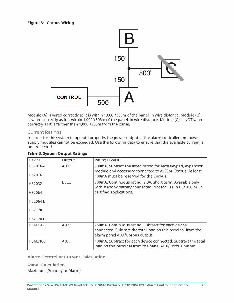
Figure 3: Corbus Wiring
Module (A) is wired correctly as it is within 1,000'/305m of the panel, in wire distance. Module (B)is wired correctly as it is within 1,000'/305m of the panel, in wire distance. Module (C) is NOT wiredcorrectly as it is farther than 1,000'/305m from the panel.
Current RatingsIn order for the system to operate properly, the power output of the alarm controller and powersupply modules cannot be exceeded. Use the following data to ensure that the available current isnot exceeded.Table 3: System Output RatingsDevice Output Rating (12VDC)
AUX: 700mA. Subtract the listed rating for each keypad, expansionmodule and accessory connected to AUX or Corbus. At least100mA must be reserved for the Corbus.
HS2016-4
HS2016
HS2032
HS2064
HS2064 E
HS2128
HS2128 E
BELL: 700mA. Continuous rating. 2.0A. short term. Available onlywith standby battery connected. Not for use in UL/ULC or ENcertified applications.
HSM2208 AUX: 250mA. Continuous rating. Subtract for each deviceconnected. Subtract the total load on this terminal from thealarm panel AUX/Corbus output.
HSM2108 AUX: 100mA. Subtract for each device connected. Subtract the totalload on this terminal from the panel AUX/Corbus output.
Alarm Controller Current Calculation
Panel CalculationMaximum (Standby or Alarm)
25PowerSeries Neo HS2016/HS2016-4/HS3032/HS2064/HS2064 E/HS2128/HS2129 E Alarm Controller ReferenceManual

AUX (700mA max. including PGMs 1-4)
Corbus (700mA max.)***
PCLink+ (Alt. Com.:125mA)
Total (must not exceed 700mA)
***See Corbus Current Calculation Chart.For UL, ULC and Commercial Listed applications, the total standby and alarm current cannot exceedvalues in Table 4 .Table 4: Corbus Current Calculation ChartItem Current (mA) x Quantity Total (mA)HS2016-4/HS2016/HS2032/HS2064/HS2064 E/HS2128/HS2128 E
85 x 1 85
HS2LCD 105 x
HS2ICN 105 x
HS2LED 105 x
HS2LCDP 105 x
HS2ICNP 105 x
HS2LCDRF 105 x
HS2ICNRF 105 x
HS2ICNRFP 105 x
HS2TCHP 160 x
Current required for connected devices =
HSM2300* 30 x
AUX output current of HSM2108
HSM2208* 40 x
AUX output current of HSM2208
HSM2300/2204* 35 x
HSM2HOSTx 35 x
HSM2955** x
3G2080(R)E/TL2803G(R)E/TL280(R)E
125 (PCLINK) x
Total Corbus Current =
PowerSeries Neo HS2016/HS2016-4/HS3032/HS2064/HS2064 E/HS2128/HS2129 E Alarm Controller ReferenceManual
26

*These units draw current from the Corbus to power devices external to the module. This currentmust be added to the total Corbus current. See manufacturer's specifications for the current drawof each device.** For HSM2955 current draw refer to HSM2955 installation manual.
Line Loss
Voltage loss through wire resistance must be considered for all installations. To ensure properoperation, at least 12.5Vdc must be applied to all modules on the system (when AC is connectedand the battery is fully charged). If less than 12.5Vdc is applied, system operation is adverselyaffected.
To correct the problem, try any or all of the following:
1. Connect a PowerSeries Neo power supply between the alarm controller and the module toprovide additional power to the Corbus.
2. Reduce the length of the Corbus run to the module.3. Increase the gauge of wire.
Capacitance LimitsAn increase in capacitance on the Corbus affects data transmission and causes the system to slowdown. Capacitance increases for every foot of wire added to the Corbus. The capacitance rating ofthe wire used will determine the maximum length of the Corbus.For example, 22-gauge, non-shielded, 4-conductor wire has a typical capacitance rating of 20picofarads per foot (which is 20nF/1000’). For every 1000' of wire added – regardless of where it isrun – the capacitance of the Corbus increases by 20nF.The following table indicates the total wire distance allowed for the capacitance rating of the wireused:Table 5: Wire CapacitanceWire Capacitance per 1000’ (300m) Total Corbus Wire Length15nF 5300’/1616m20nF 4000’/1220m25nF 3200’/976m30nF 2666’/810m35nF 2280’/693m40nF 2000’/608m
Installing ModulesRemove all power from the system while connecting modules to the alarm controller.
Zone ExpanderThe main alarm controller has connection terminals for zones 1 to 8. Additional HSM2108 zoneexpanders may be added to increase the number of zones on the system. Each zone expanderconsists of one group of 8 zones. At enrollment, the zone expander is automatically assigned to thenext available zone slot. Connect the RED, BLK, YEL and GRN terminals to the Corbus terminals onthe alarm panel. Board current draw: 30mA.
27PowerSeries Neo HS2016/HS2016-4/HS3032/HS2064/HS2064 E/HS2128/HS2129 E Alarm Controller ReferenceManual

Figure 4: HSM2108 Zone Expander
Refer to the HSM2108 installation sheet for more information.
Output ExpanderThe HSM2208 module is used to add up to 8 low-current programmable outputs to the alarmsystem.The 4-wire Corbus connection is used by the panel to communicate with the module. Connect theRED, BLK, YEL and GRN terminals to the Corbus terminals on the alarm panel. Board current draw:40mA.
Figure 5: HSM2208 Output Expander
Wireless Transceiver ModuleThe HSM2HOSTx 2-way wireless integration module provides communication between wirelessdevices and the alarm controller.Connect the HSM2HOSTx to the 4-wire Corbus of the alarm controller according to the followingdiagram.
PowerSeries Neo HS2016/HS2016-4/HS3032/HS2064/HS2064 E/HS2128/HS2129 E Alarm Controller ReferenceManual
28

Figure 6: HSM2HOSTx Wiring Diagram
After you have completed the wiring, reconnect power to the security system. Board current draw:35mA
Power Supply WiringThe HSM2300/2204 power supply/high-current output module provides up to 1.0A of additionalcurrent and can be used to add up to four programmable outputs (HSM2204 only) to the alarmsystem.The 4-wire Corbus connection provides communication between the module and alarm panel.Connect the RED, BLK, YEL and GRN terminals to the Corbus terminals on the alarm controller. If O1is not used, connect to Aux with a 1K resistor. Board current draw: 1.2A.
Figure 7: Power Supply Wiring
Keypad WiringTo wire a keypad to the alarm controller, remove the keypad backplate (refer to the keypadinstallation sheet) and connect the RED, BLK, YEL and GRN terminals to the correspondingterminals on the alarm controller.
29PowerSeries Neo HS2016/HS2016-4/HS3032/HS2064/HS2064 E/HS2128/HS2129 E Alarm Controller ReferenceManual

Keypad Zone/PGM WiringHardwired devices can be connected to hardwired keypads with inputs (zone) or outputs (PGM).This saves from running wires back to the control panel for every device.To connect a zone device to HS2LCD, HS2ICON, HS2LED and HS2TCHP keypads, run one wire to theP/Z terminal and the other to B. For powered devices, use red and black to supply power to thedevice. Run the red wire to the R (positive) terminal and the black wire to the B (negative) terminal.Keypad zones support Normally Closed Loops, Single End of Line and Double End of Line.To connect the PGM output, run one wire to the P/Z terminal and the other to R.
Figure 8: Keypad Terminals
Note: When using end of line supervision, connect the zone according to one of theconfigurations outlined in Zone Wiring. End of line resistors must be placed on the device endof the loop, not at the keypad.
Assigning Keypad ZonesWhen using keypad zone inputs, each input used must be assigned a zone number in InstallerProgramming.First, ensure that you have enrolled all installed keypads into the desired slots ([902] Add/RemoveModules). Next, assign keypad zones by entering programming section [861]-[876], subsection 011for keypads 1-16. Enter a 3-digit zone number for each of the keypad zones. This number must beprogrammed into the slot location that the keypad is assigned to.
Note: If a keypad zone input is assigned to zone number 1 to 8, the corresponding zonecannot be used on the main control panel.
Once the keypad zones are assigned, you must also program zone definitions and zone attributes.[001] AssignZone Types and Zone Setup.
HSM2955 WiringFor wiring information refer to HSM2955 Installation manual.
Alternate Communicator WiringSee Alternate Communicator installation manual.
Zone WiringPower down the alarm controller and complete all zone wiring.Zones can be wired to supervise normally open devices (e.g., smoke detectors) or normally closeddevices (e.g., door contacts). The alarm panel can also be programmed for single end-of-line ordouble end-of-line resistors.Zone programming is done using the following programming sections:
• [001] selects zone definition
PowerSeries Neo HS2016/HS2016-4/HS3032/HS2064/HS2064 E/HS2128/HS2129 E Alarm Controller ReferenceManual
30

• [013] Opt [1] for normally closed or EOL; Opt [2] for SEOL or DEOL• [201 - 208] partition assignment.
Observe the following guidelines when wiring zones:
• For UL listed installations use SEOL or DEOL only• Minimum 22 AWG wire, maximum 18 AWG• Do not use shielded wire• Do not exceed 100 Ω wire resistance. Refer to the following table:
Table 6: Burglary Zone Wiring ChartWire Gauge Maximum Length to EOL Resistor (ft/meters)22 3000 / 91420 4900 / 149319 6200 / 188918 7800 / 2377Figures are based on maximum wiring resistance of 100 Ω.
Normally ClosedConnect hardwired devices to any Z terminal and any Com terminal. Wire normally closed devices inseries.
Note: For UL Installations, do not use normally closed loops.
Figure 9: Normally Closed
The following table shows zone status under certain conditions for NC Loops:Table 7: NC Loop StatusLoop Resistance Loop Status0Ω (shorted wire, loop shorted) SecureInfinite (broken wire, loop open) Violated
Single End-of-Line (SEOL) ResistorWhen SEOL resistors are installed at the end of a zone loop, the alarm panel detects if the circuitis secure, open, or shorted. The SEOL resistor must be installed at the end of the loop for propersupervision.To enable SEOL supervision, program section [013], options [1] and [2] to OFF.
Note: This option should be selected if either normally closed or normally open detectiondevices or contacts are used.
31PowerSeries Neo HS2016/HS2016-4/HS3032/HS2064/HS2064 E/HS2128/HS2129 E Alarm Controller ReferenceManual

Figure 10: SEOL Wiring
The following table shows zone status under certain conditions for SEOL:Table 8: SEOL Loop StatusLoop Resistance Loop Status0Ω (shorted wire, loop shorted) Violated5600Ω (contact closed) SecureInfinite (broken wire, loop open) Violated
Double End of Line (DEOL) ResistorsWhen double end-of-line (DEOL) resistors are installed at the end of a zone loop, the secondresistor enables the panel to determine if the zone is in open, closed, tampered or faulted.
Note: Any zone programmed for Fire or 24-hr Supervisory must be wired with a SEOL resistorregardless of the type of zone wiring supervision selected for the panel. If you change thezone supervision options from DEOL to SEOL or from NC to DEOL, power the system downcompletely, then power it back up for correct operation.To enable DEOL supervision, programsection [013], option [1] to OFF and option [2] to ON.
Figure 11: DEOL Wiring
Note: If the DEOL supervision option is enabled, all hardwired zones must be wired for DEOLresistors, except for Fire and 24 Hour Supervisory zones. Do not use DEOL resistors for Firezones or 24 Hour Supervisory zones.
Note: Do not wire Fire zones to keypad zone terminals if the DEOL supervision option isselected.
Note: This option can only be selected if N/C detection devices or contacts are used. Only oneN/C contact can be connected to each zone.
The following table shows zone status under certain conditions for DEOL:
PowerSeries Neo HS2016/HS2016-4/HS3032/HS2064/HS2064 E/HS2128/HS2129 E Alarm Controller ReferenceManual
32

Table 9: DEOL Loop StatusLoop Resistance Loop Status0Ω (shorted wire, loop shorted) Fault5600Ω (contact closed) SecureInfinite (broken wire, loop open) Tamper11200Ω (contact open) Violated
PGM WiringMin/max operating voltages for devices, sensors and modules is 9.5VDC - 14VDC. PGMs switch toground when activated from the alarm controller. Connect the positive side of the device to the AUX+ terminal and the negative side to a PGM terminal. PGM 1, 3, 4 supply up to 50mA; PGM 2 suppliesup to 300mA.A relay is required for current levels greater than 50mA or 300mA. PGM2 can also be used for 2-wiresmoke detectors, 24-hr burglary input alarm.
Note: Use SEOL resistors on Fire zones only.
Figure 12: LED Output with Current Limiting Resistor and Optional Relay Driver Output.
Bell WiringThese terminals supply 700mA of current at 10.4 - 12.5VDC for commercial/ residential installations.To comply with NFPA 72 Temporal Three Pattern requirements, section [013] Opt [8] must be ON.Note that steady, pulsed alarms are also supported.
Figure 13: Bell Wiring
The Bell output is supervised and power limited by 2A thermistor. If unused, connect a 1000 Ωresistor across Bell+ and Bell- to prevent the panel from displaying a trouble. Troubleshooting.
Telephone Line WiringWire the telephone connection terminals (TIP, Ring, T-1, R-1) to an RJ-31x connector as indicatedin the following diagram. For connection of multiple devices to the telephone line, wire in thesequence indicated. Use 26 AWG wire minimum for wiring.
33PowerSeries Neo HS2016/HS2016-4/HS3032/HS2064/HS2064 E/HS2128/HS2129 E Alarm Controller ReferenceManual

Figure 14: Telephone Line Wiring
Note: Ensure that all plugs and jacks meet the dimension, tolerance and metallic platingrequirements of 47 C.F.R. Part 68, Sub-Part F. For proper operation, no other telephoneequipment must be connected between the control panel and the telephone companyfacilities.
Smoke Detector WiringAll zones defined as Fire must be wired according to the following diagram:
Figure 15: Smoke Detector Wiring
See[001] AssignZone Types for fire zone operation.
Note: Smoke detectors must be latching type. To reset a smoke detector, enter [*][7][2].
Table 10: Table 19 Compatible 4-Wire Smoke Detectors4-wire smoke detectors -System Sensor4W-B(UL)/C4W-BA(ULC) 4-wire Standard i3 Detector4WT-B(UL) / C4WT-BA(ULC) 4-wire Standard i3 Detector with Fixed 135° Thermal Sensor4WTA-B 4-wire i3 Detector with Fixed 135° Thermal Sensor and Sounder4WTR-B 4-wire i3 Detector with Fixed 135° Thermal Sensor and Form C Relay4WTAR-B 4-wire i3 Detector with Fixed 135° Thermal Sensor, Sounder and Form C RelayRatings: 10-35Vdc/50mA (max)
Note: If you use a non-powered heat detector, such as a fixed temperature or rate of rise type,no supervision relay is required and you should not wire the detector to a power output orPGM2. To wire a 4-wire smoke, heat, or CO detector, see the figure above.
Fire Zone Wiring: 2-wire Smoke DetectorsIf PGM 2 is programmed for 2-wire smoke detector connection, the detectors must be wiredaccording to the following diagram:
PowerSeries Neo HS2016/HS2016-4/HS3032/HS2064/HS2064 E/HS2128/HS2129 E Alarm Controller ReferenceManual
34

Figure 16: 2-Wire Smoke Detector Wiring
Note: Additional 2-wire smoke detectors must be connected in parallel as shown above. Themaximum number of smoke detectors on a 2-wire loop is 18.
Note: Do not combine smoke detector models from different manufacturers on the samecircuit. Operation may be impaired. Refer to the smoke detector installation sheet whenpositioning detectors.
Table 11: Table 19 Compatible 2-Wire Smoke DetectorsSystem Sensor2W-B (UL)2WT-B (UL)2WTA-B (UL)C2W-BA (ULC)C2WT-BA (ULC)C2WTA-BA (ULC)
Note: If you use system sensor detectorson a 2-wire loop, do not combine UL andULC detectors. For more information, referto the System Sensor installation manual.
Do not connect accessories, for example, apolarity
reversal module to a 2-wire smoke detectorloop.
The UL compatibility ID for the systemsensor models is A.
Table 12: Table 1-2 2-Wire Smoke Detector Initiating CircuitItem SpecificationStyle/Class, Supervised, Power Limited Style B (Class B)Compatibility Identifier HS2-1DC Output Voltage 9.4 - 13.8 VDetector Load 2mA (MAX)Single End of Line Resistor (SEOL) 2200WLoop Resistance 24Ω (MAX)Standby Impedance 1250Ω (MIN)Alarm Impedance 650Ω (MAX)Alarm Current 86mA (MAX)
CO DetectorThe following hardwired CO detector models can be used with PowerSeries Neo alarm controllers:
• System Sensor, Models CO1224, CO1224T, CO1224TR, UL Listed in File E307195; ModelCO1224A, ULC Listed in File E304075
• Macurco, Model CM-E1, UL File E354878
35PowerSeries Neo HS2016/HS2016-4/HS3032/HS2064/HS2064 E/HS2128/HS2129 E Alarm Controller ReferenceManual

• Potter, Model CO-12/24, UL File E321434• Quantum, Model 12-24SIR, UL File E186246
Note: For multiple unit connections, the leads between CO detectors must be broken. Thepower supervision relay must be powered from the last detector in the loop.
Wireless CO detectors are also available. When installing wireless CO detectors, use only modelPG9913UL, PG8913, PG4913. An HSM2HOSTx (x=9UL/8/4) wireless receiver or HS2LCDRF(P)x/HS2ICNRF(P)x (x=9UL/8/4) wireless keypad are required when installing wireless CO detectors. Formore details on these wireless devices, refer to their respective installation manuals.
Note: Use only UL approved devices with UL/ULC listed systems.
Table 13: Table 19 CO Detector RatingsDevice Description Max RatingCM-E1 Marcurco CO Detector Current (normal / alarm):
15mA / 35mA @ 9-32VCO-12/24 Potter CO Detector 40mACO1224, CO1224T,
CO1224TR, CO1224A
System Sensor model COdetector
40mA
12-24SIR Quantum CO Detector 75mA
Figure 17: CO Detector Wiring
PowerSeries Neo HS2016/HS2016-4/HS3032/HS2064/HS2064 E/HS2128/HS2129 E Alarm Controller ReferenceManual
36

Ground Wiring
Figure 18: Ground Installation
Note: Using an insulated green wire (minimum 22AWG), connect the EGND terminal on theCorbus and the grounding wire from the building electrical installation to any of the availableholes on the back or side of the metal cabinet. See the diagram attached to the cabinet forsuggested GND point location and hardware recommendations.
Note: Wire and installation hardware not included.
Connecting Power
BatteriesDo not connect the battery until all other wiring is complete.
Note: A sealed, rechargeable, lead acid battery or gel type battery is required to meet ULrequirements for power standby times.
Connect the RED battery lead to the positive battery terminal and the BLACK battery lead to thenegative battery terminal.The panel can be programmed to charge the battery at 400mA or 700mA. ([982] Battery Settings).
Note: Aux Loading and Battery Selection
Battery Selection ChartAfter calculating the battery capacity (B) for each specific installation use the following table todetermine the battery required to support the main panel in standby mode for:
• 4 hours (UL commercial burglary/residential burglary)• 12 hours (EN50131)• 24 hours (UL/ULC residential fire, ULC residential burglary, ULC commercial burglary, ULC
commercial fire monitoring - no bell load allowed; INCERT [Belgium])
37PowerSeries Neo HS2016/HS2016-4/HS3032/HS2064/HS2064 E/HS2128/HS2129 E Alarm Controller ReferenceManual

The battery size is measured in amp hours (Ah). The current values in the table denote themaximum current draw permitted to achieve the desired standby time with the listed battery types.Table 14: Table 19 Standby Battery GuideBattery Size Desired Standby Time
4h 12h 24h 36h
4Ah 700mA ------ ------ ------7Ah 700mA 500mA 250mA ------14Ah * 700mA 470mA ------
18Ah ------ ------ ------ 300mA*26Ah ------ ------ ------ 500mA*
* use 2 x 7Ah batteries connected in parallel, UL/ULC installations onlyBattery capacity deteriorates with age and the number of charge/discharge cycles. Replace every3-5 years.Refer to Regulatory Approvals for detailed Aux. loading and battery charging information.
Connecting AC PowerThe alarm controller requires a 16.5V, 40VA transformer. While unplugged, connect the transformerto the AC terminals on the controller. The alarm controller can be programmed to accept a powerline frequency of either 50Hz AC or 60Hz AC. See programming section [024], option [1].
Note: For UL/ULC installations use only 60Hz.
Note: For ULC S559 applications, Standex transformer (Model FTC3716) shall be employed fordirect-wiring.
Configuration
Basic Configuration StepsOnce basic installation of the alarm panel is complete, the following general configuration optionsshould be set:
• create partitions, Working with Partitions
• assign keypads to partitions, Keypad Partition Setup
• assign sirens to partitions, Bell/Siren Operation
• create global zones, Global Zones
• set up partition account codes, Communications
• set up partition timers, System Times
• enroll wireless modules and devices, Enrolling Modules
• assign zone types, [001] AssignZone Types, and attributes, [002] Zone Attributes
• create zone labels, Adding Labels
• add users, Assign Access Codes
• set up the alternate communicator if equipped, Alternate Communicator Setup
PowerSeries Neo HS2016/HS2016-4/HS3032/HS2064/HS2064 E/HS2128/HS2129 E Alarm Controller ReferenceManual
38

• program phone numbers, System Communications
• set up call directions for the central monitoring station, System Communications
• set up system timers, System Times
• configure reporting codes, Reporting
• test the system, Testing the System
Using the KeypadThe PowerSeries Neo alarm panel is compatible with several different keypad types (CompatibleDevices); However, all keypads have certain basic functionality in common.
Special KeysScroll symbols < > on keypads with LCD displays indicate that options can be viewed by pressing thescroll keys. These keys can also be used to position the cursor.The [*] key is similar in function to the “Enter” key on a personal computer. It is generally used toaccept the existing programming option. It is also the first key entry for [*] commands and can beused to enter the letters A-F when in Installer Programming mode.The [#] key is similar in function to the “ESC” (escape) key on a personal computer. It is generallyused to exit the current programming section or to return to the previous one.
LED IndicatorsKeypads have the following status lights that provide visual indication of basic system status:
Ready: Panel is ready to be armed.
Armed: Panel is armed.
Trouble: System trouble. Enter [*][2] to viewtroubles.
AC Power: ON=AC present. OFF=AC absent.
Panel Status LED OperationThe red status LED, located on the alarm controller PCB, indicates the following:
• Power up sequence – flashes rapidly until the end of the power-up sequence.• Firmware indication – flashes during the firmware upgrade process. If the firmware upgrade
fails, the LED flashes rapidly.• Trouble indication – Flashes when troubles are present. Troubles are indicated according to the
following priority:
1 flash - no keypads enrolled2 flashes - module supervision trouble3 flashes - bus low voltage
39PowerSeries Neo HS2016/HS2016-4/HS3032/HS2064/HS2064 E/HS2128/HS2129 E Alarm Controller ReferenceManual

4 flashes - low battery trouble5 flashes - AC trouble6 flashes - AUX trouble7 flashes - bell trouble8 flashes - TLM trouble
How to Enter Data
Conventions Used In This ManualBrackets [ ] indicate numbers or symbols that must be entered on the keypad.e.g., [*][8][Installer Code][804] requires the following key entries:[*][8][5555][804][*] initiates a special command.[5555] is the default installer code. The default installer code should be changed during initialprogramming of the system.[804] indicates the particular programming section being accessed.
Entering Letters Manually (System Labels)
1. In Installer Programming, enter the section requiring text input.2. Use the arrow keys [<][>] to move the cursor to a blank space or existing character.3. Press the number key corresponding to the appropriate letter. Each number button accesses
three letters and a number. The first press of the number key displays the first letter. Thesecond press displays the second letter, etc.
1
A, B, C, 1
2
D, E, F, 2
3
G, H, I, 34
J, K, L, 4
5
M, N, O, 5
6
P, Q, R, 67
S, T, U, 7
8
V, W, X, 8
9
Y, Z, 9,00
Space
4. To select lower case letters press [*]. The Select Options list opens. Scroll to “lower case” andpress [*] again to select.
5. When the required letter or number is displayed use the arrow keys [<][>] to scroll to the nextletter.
6. When finished, press the [*] key, use the [<][>] keys to scroll to “Save” then press [*].7. Continue from step 2 until all labels are programmed.
For information on entering hexadecimal data, see Programming Hex and Decimal Data.
EnrollmentAll optional modules and devices must be enrolled on the system. During enrollment, the electronicserial number (ESN) of each device is identified to the control panel and zones are assigned. A
PowerSeries Neo HS2016/HS2016-4/HS3032/HS2064/HS2064 E/HS2128/HS2129 E Alarm Controller ReferenceManual
40

wireless transceiver HSM2HOST or an RF keypad must be enrolled first before wireless devices canbe enrolled.
Enrolling ModulesDuring automatic and manual enrollment, if an attempt is made to enroll more than the maximumnumber of modules, an error tone sounds and a message is displayed on LCD keypads.Table 15: Module CapacityModule HS2016-4 HS2016 HS2032 HS2064/ HS2064E HS2128/HS2128EHSM2108 8 Zoneexpander
1 1 3 7 15
HSM2208 8 Outputexpander
2 2 4 8 16
HS2LCD(P)XHS2ICN(P)XHS2LCDWF(P)(V)X
8 8 8 8 16
HS2TCHPTouchscreenKeypad
8 8 8 8 16
HSM2300 PowerSupply 1A
3 3 3 3 4
HSM2204 4 High-current Output
1 1 1 3 4
Transceiver:HSM2HOSTxKeypads:HS2LCDRF(P)XHS2ICNRF(P)X
1 1 1 1 1
HSM2955(not UL evaluated)
1 1 1 1 1
Modules can be enrolled automatically or manually using section [902] of Installer programming.For instructions on enrolling modules, Module Programming.To confirm that a module has been successfully enrolled, use Installer Programming section [903].[903] Confirm Module for details.
Enrolling the First KeypadTo enroll a hardwired keypad, connect the keypad to the alarm controller, power up the alarm panelthen press any button on the keypad.To enroll a wireless keypad, first connect the HSM2HOSTx wireless integration module to the alarmcontroller. Next, power up the alarm panel and a wireless keypad. Press any button on the keypadto enroll it on the HSM2HOSTx. The HSM2HOSTx is then enrolled on the alarm panel. To enroll otherkeypads, Module Programming.
Module SupervisionBy default, all modules are supervised upon installation. Supervision is enabled at all times so thatthe panel can indicate a trouble if a module is removed from the system.To check which modules are currently connected and supervised, [903] Confirm Module.If a module is connected but is not recognized by the system, it may be due to any of the followingreasons:
• the module is incorrectly wired to the alarm controller• the module has exceeded its maximum wire run length
41PowerSeries Neo HS2016/HS2016-4/HS3032/HS2064/HS2064 E/HS2128/HS2129 E Alarm Controller ReferenceManual

• the module does not have enough power• the module is not enrolled on the wireless receiver
Removing ModulesEnrolled modules can be deleted from the system via programming section [902]. For instructions,[902] Add/Remove Modules.
Enroll Wireless DevicesWireless devices are enrolled via the wireless transceiver module and Installer Programmingsection [804][000]. Compatible Devices for a list of supported wireless devices.Wireless devices are enrolled using one of the following methods:
Auto EnrollmentTo enroll a wireless device using this method, press and hold the Enroll button on the device for2-5 seconds until the LED lights then release the button. The alarm panel automatically recognizesthe device and the keypad displays a confirmation message. The device ID and next available zonenumber are displayed. Press [*] to accept or scroll to another available zone number. Batteriesmust be installed in the wireless device in order to enroll.Various zone features are programmable depending on the type of device. Zone Setup for details.
Pre-EnrollmentPre-enrollment is a two step process. The first step requires entering each device ID ([804][001]-[716]). Every wireless device has an ID printed on the sticker attached to the device. The format isXXX-YYYY where:
• XXX identifies the type or model of the device• YYYY is a short encrypted ID used by the system to identify the specific device
Pre-enrollment can be done at a remote location and using DLS/SA. The second step is to press theenrollment button on the device, usually done on location. Installer Programming does not have tobe entered at this step. Both steps must be performed in order to complete the enrollment.
Working with PartitionsA partition is a limited area of the premises that operates independently from the other areas.Partitioning a system can be beneficial if the property has outbuildings that need to be securedindependently of a main area or if the home has a separate apartment.Each partition can have its own keypad or a keypad can have access to all partitions (only if allpartitions belong to the same owner). User access to partitions is controlled via access codes. Amaster code can access the entire system and partitions, while a user code is limited to assignedpartitions.Setting up a partition requires configuration of the following:
• create the partition• define bell/siren operation• assign keypads• assign zones• assign users
PowerSeries Neo HS2016/HS2016-4/HS3032/HS2064/HS2064 E/HS2128/HS2129 E Alarm Controller ReferenceManual
42

Setting Up a PartitionPartitions are added or removed from the system by applying or removing a partition mask viaInstaller Programming section [200]. The number of available partitions depends on the alarmpanel model. [200] Partition Mask for more information.
Bell/Siren OperationEach partition must have a siren. The system siren connected to the bell output of the alarmcontroller can be mounted in a central location within hearing range of all partitions. Each partitioncan also have wireless sirens activated only on the assigned partition. See Wireless Programmingfor details.
Single Siren Output OperationWith a siren shared across all partitions, control over activation/deactivation of the output dependson the partition that initiated the alarm sequence. Only the partition that originated the alarm candeactivate the bell output.Global zones, such as smoke detectors shared by multiple partitions, can deactivate the siren on allpartitions the zone is assigned to.
Multiple Siren Output OperationWhen multiple sirens are used in the installation, they can be programmed to sound alarmconditions for all partitions, or for individual partitions by using a partition enable mask.If hardwired sirens are used, this is accomplished via bus power supplies with a supervised high-current output. The output is then programmed as a Fire and Burglary PGM output type.
Note: Only the first output of the HSM2204 output module has bell supervision. Someconditions, such as an installer system test, may override the partition assignment and causeall sirens to activate. User system tests only activate the sirens/outputs assigned to thatpartition.
Interconnected Smoke Detector OperationWhen the Fire Alarm toggle is enabled ([804][001]-[128] option 14) on a zone with a PowerG smokedetector, any fire alarm on a partition assigned to the detector activates the sounder. Globalfire alarms activate the sounder on all smoke detectors.The sounder on interconnected smokedetectors follows the panel bell for duration of activation ([014] option 8, Fire Bell Timeout). If thisoption is disabled, interconnected smoke detectors continue to sound the alarm until the bell isdeactivated on the panel.The following alarm types cause interconnected smoke alarms to sound:- Fire zones- [F] key alarms- 2 Wire smoke input
Trouble IndicatorsBoth audible and visual trouble indications are available on all partitions. For more information, seeTroubleshooting.Programming section [013] option 3 controls whether or not troubles are indicated when the alarmsystem is armed.
43PowerSeries Neo HS2016/HS2016-4/HS3032/HS2064/HS2064 E/HS2128/HS2129 E Alarm Controller ReferenceManual

Keypad Partition SetupKeypads can be configured to control an individual partition or all partitions. In general, a partitionkeypad controls the partition it is assigned to. A Global keypad controls all partitions. Globalkeypads should be placed in common areas of the premises, such as points of entry or receptionareas, where the ability to arm and disarm more than one partition at a time is required. Partitionkeypads can also be temporarily loaned to other partitions. To select a keypad operating mode:
1. Enter Installer Programming: [*][8][installer code].2. Select [861]-[876] to program keypads 1-16.
- Press [000] for partition assignment.- For Global operation, key in 00.- To assign a keypad to a partition, key in 01-08 for partition 1-8.
3. Press the [#] and reapeat step 2 for next keypad. When finished programming all keypads,press the [#] key twice to exit programming.
Users are assigned partition access rights via the [*][5] menu.
Loaned Partition SetupTo loan a keypad to another partition:
1. Press and hold [#] then key in a valid access code. The keypad switches to Global display.2. Use the arrow keys to scroll through available partitions. Press [*] to select. The keypad is
temporarily loaned to another partition.If the keypad is inactive for more than 30 seconds, it reverts to its assigned partition.
Global ZonesIf a zone is added to more than one partition, it becomes a global zone. A global zone is only armedwhen all assigned partitions are armed and is disarmed when any assigned partition is disarmed.Global zones behave as follows:
• A global Stay/Away type zone is not activated until all partitions the zone is assigned to arearmed in the Away mode. Interiors must be activated on all partitions for the global Stay/Awayzone to be active.
• A shared zone bypassed on one partition is bypassed on all partitions the zone is assigned to.• An entry delay started on a global zone sounds an entry delay on all keypads assigned to
partitions the global zone is assigned to.• A global Delay type zone follows the longest programmed delay time of the partitions it is
assigned to.
Fire and CO Zone Types
• Fire zones only place the partition they are assigned to into alarm. Other partitions retain theircurrent state. A fire reset only resets assigned partitions.
• One or more fire zones may be located on any partition.• On alarm, the fire auto-scroll display appears on all partition keypads and on all global
keypads. Fire alarm silence and fire system reset may be done directly on any partition keypad.
PowerSeries Neo HS2016/HS2016-4/HS3032/HS2064/HS2064 E/HS2128/HS2129 E Alarm Controller ReferenceManual
44

• To silence a fire or CO alarm from a global keypad requires that the global keypad be loaned toone of the partitions the zone is assigned.
Note: The LCD keypad displays "Bell Silenced" after a fire or CO alarm is silenced with a usercode. The display is cleared when all the fire zones or CO zones have been restored on system.
Bell/PGM SupportPGMs must be assigned to one or more partitions. See section [007] for partition assignment.
Note: Bell PGM type requires supervision and follows arming squawks by partition.
CommunicationsAccount codes are assigned to all system and partition events.For SIA communications, a single account code (programmed in section [310][000]) is used for allevents. The partition is identified via Nri1-8. System events use Nri0.When using communication formats other than SIA, individual account codes can be programmedfor each partition. [310] Account Codes.
Assign ZonesPartition zone assignments are completed using sections [201] - [208] for partitions 1 - 8.Subsections [001 - 016] are then used to enable or disable banks of 8 zones on the partition.
Assign UsersAcess [*][5] using the master code, select the desired user code and enter digit 4 to modify thepartitions that can accept the user code.
Factory DefaultsIndividual modules, as well as the alarm panel itself, can have their programming returned tofactory default settings. Hardware is defaulted via the following Installer Programming sections:
• [991] Default Keypads
- – Default all keypad programming- 001-016 – Default keypads 1-8
• [993] Default alternate communicator• [996] Default wireless receiver• [998] Default HSM2955• [999] Default system
See Defaults for more information.
Default All labelsUse programming section [000][999]. The following labels are returned to factory default settings:
• Zone Label• Partition Labels• Module Labels• Partition 1-8 Command Output 1 to 4 Labels• Schedule 1 to 4 Labels• Event Labels
45PowerSeries Neo HS2016/HS2016-4/HS3032/HS2064/HS2064 E/HS2128/HS2129 E Alarm Controller ReferenceManual

• User Labels
System and module programming is not affected.
Hardware Reset Main Control Panel
Perform the following to restore the main control panel to default settings:
1. Power down the system.2. Remove all wires between Zone 1 and PGM 1 on the alarm controller.3. Connect a short between Zone 1 and PGM.4. Power up the system (AC only) for 60 seconds.5. Power down the system and remove the short.6. Power up the system again. Factory defaults are restored.
Hardware default is logged to the event buffer.
Note: Hardware default is not available when installers lockout is enabled
Alternate Communicator SetupThe alternate communicator is an optional wireless or ethernet communications device that can beused as a backup to the PSTN connection or as a primary means of communication between thealarm panel and the central monitoring station. The alternate communicator communicates via 3G(HSPA) or Ethernet.The following configuration steps are required to set up the alternate communicator:
• Install the alternate communicator and wire it to the alarm panel (use PCLINK_2 header)• Enroll the alternate cellular communicator with Connect 24• Set the communication path: [300]• Enable the alternate communicator: [382] option 5• Enable event reporting: [307]/[308]• Program communication delay timer: [377]• Program DLS access: [401] option 07
Refer to the 3G2080(R)E/ TL2803G(R)E/ TL280(R)E installation manual for details.
Real Time ClockThis feature synchronizes the alarm panel time and date with that of the alternate communicator,provided real time clock support is available. Time and date are updated at 4:05 PM or when thesystem time is lost. This feature is enabled/disabled in Installer Programming section [024] option5.
Communication PathsThe path of communication between the alarm panel and the central station must be establishedthrough either the alarm panel’s on-board Public Switched Telephone Network (PSTN) connectionor through the alternate communicator (cellular or Ethernet) if equipped.Paths to four receivers can be programmed in Installer Programming section [300] options 001 -004.For more information, [300] Panel/Receiver Communication Paths.
PowerSeries Neo HS2016/HS2016-4/HS3032/HS2064/HS2064 E/HS2128/HS2129 E Alarm Controller ReferenceManual
46

Communications OptionsThe following alarm panel options must be programmed when configuring the alternatecommunicator:[300] option 02: communication path ([300] Panel/Receiver Communication Paths)[380] option 01: communications enabled/disabled ([380] Communicator Option 1)[382] option 05: enable communicator and all associated options: telephone number, reportingcode and call direction ([382] Communicator Option 3)[308][351]-[356] reporting codes ([351] Alternate Communicator 1)[401] option 7: DLS access ([401] System Test Events)
Communication Attempt LimitIf a telephone line monitoring (TLM) trouble is present, the number of PSTN dialing attempts isreduced from the programmed value to 0 attempts. See programming section [380] CommunicatorOption 1 for details.
Supervision RestoreIf the alarm system experiences a failure to communicate (FTC) with the central monitoring station,it automatically attempts to transmit the event when communications are restored.
Remote Firmware UpgradeFirmware upgrades can be automatically pushed to the alarm panel and modules from Connect 24or DLS. A message is displayed on LCD keypads indicating a firmware upgrade is available. On allkeypads, the blue proximity tag bar flashes one second on - one second off.Users authorize the firmware upgrade through [*][6][Master Code][17].During the update, a message indicating that a firmware upgrade is in progress is displayed on theLCD keypad. If the firmware update fails, an error message is displayed on LCD keypads.Firmware updates are performed under the following conditions:
• The system is not armed• No AC trouble is present• No low battery trouble is present• No FTC trouble is present• Every alarm in memory has been viewed• No events are being communicated• An alternate communicator is present
Remote firmware upgrade is possible for the following modules:
• hardwired keypads, including HS2LCDRF• wireless transceivers• alternate communicators
Note: For UL listed installations, do not use remote programming unless an installer is on thepremises.
47PowerSeries Neo HS2016/HS2016-4/HS3032/HS2064/HS2064 E/HS2128/HS2129 E Alarm Controller ReferenceManual

Local Firmware UpgradeAlarm panel firmware can be upgraded locally via DLS. Firmware upgrade prevention rules areignored when performing a local firmware upgrade.
To perform a local firmware upgrade:
Note: [382][5] must be enabled to perform a local firmware upgrade.
1. Remove the front cover of the alarm panel and plug the DLS header into the PCLink 2connector on the alarm controller.
2. Open the Flash Utility within DLS, select the latest firmware file from the Web or browseto a saved flash file on your hard drive. Follow the steps as prompted by the Flash Utilityapplication. A message is displayed when download is complete.
3. Once the firmware update is complete, the system powers up.
Testing the System
Installer Walk TestWalk test enables the installer to test the operation of each detector by tripping zones, causing anactual alarm. Enter section [901] to initiate a walk test. When a zone is tripped, all system sirensemit a tone to indicate that the zone is working correctly.After 15 minutes without zone activity, the walk test terminates automatically. To manually exit walktest mode, enter [901] again.
Viewing the Event BufferThe event buffer contains logs of events that have occurred on the alarm system beginningwith the most recent. The capacity of the event buffer is scalable and can hold 500/1000 events(depending on panel model) before rolling over. The buffer displays events according to their timestamp, beginning with the most recent. The event buffer can be uploaded using DLS.Each event displays the time and date, a description of the event, the zone label, access codenumber or any other pertinent information. To view the event buffer, press [*][6][Master Code][*].
System Operation
Arming and DisarmingThe following table describes the various arming and disarming methods available.Table 16: Arming/Disarming MethodsMethod DescriptionAway Arm for 2 seconds + [Access Code*]Stay Arm for 2 seconds + [Access Code*]Night Arm when armed in stay mode [*][1] + [Access
Code*]Disarm [Access Code]No-Entry Arming [*][9] + [Access Code]Quick Arm/Quick Exit [*][0]
PowerSeries Neo HS2016/HS2016-4/HS3032/HS2064/HS2064 E/HS2128/HS2129 E Alarm Controller ReferenceManual
48

* - requiring an access code can be programmed in Section [015]For detailed arming/disarming instructions, see the PowerSeries Neo User Manual.
Partition vs. Global KeypadKeypads can be configured to control an individual partition or all partitions (Keypad PartitionSetup). Loaning a keypad to another partition does not require an access code; However, nofunction that requires an access code can be performed on that partition unless the user’s code hassufficient permission.
Single Partition OperationSingle partition keypads provide access to alarm functionality for an assigned partition. Singlepartition keypads behave as follows:
• Displays the armed state of the partition.• Displays open zones, if assigned to the partition the keypad is on.• Displays bypassed zones and allows zone bypassing or creating bypass groups of zones
assigned to the keypad partition.• Displays system troubles (system low battery, system component faults/tampers).• Displays alarms in memory that occurred on the partition.• Allows the door chime to be enabled/disabled.• Activate system test (sounds bells/PGMs assigned to the partition)• Allow label programming ( user labels for the partition)• Control command outputs (those assigned to the partition, or global outputs such as smoke
detector reset)• Display temperature (not evaluated by UL)
Global/Multiple Partition OperationGlobal keypads display a list of all active partitions or assigned partitions along with their currentstate. A valid access code is required to view partition status. The Global status screen displays thefollowing:
1 2 3 4 5 6 7 8R A ! N - - - -
R = ReadyA = Armed! = AlarmN = Not ReadyX = Exit DelayE = Entry DelayP = Pre-Alert- = Partition not enabled
49PowerSeries Neo HS2016/HS2016-4/HS3032/HS2064/HS2064 E/HS2128/HS2129 E Alarm Controller ReferenceManual

In the following example, partition 1 is armed, partition 2 is disarmed and ready, partition 3 isdisarmed and not ready, partition 4 is in alarm, partition 5 is indicating exit delay, partition 6 is inentry delay, partition 7 is in auto-arm pre-alert and partition 8 is not enabled.
1 2 3 4 5 6 7 8A R N ! X E P -
Global keypads behave as follows:
• Troubles are displayed and sounded on the global keypad. Troubles can be viewed from theglobal keypad display by pressing the right scroll key then (*). The Troubles menu is displayed.An access code may be required to enter the [*][2] menu depending on system programming.
• Keypad function keys can be programmed for Global Stay Arm, Global Away Arm and GlobalDisarm.
• Multiple partition arming/disarming may be done from a global keypad, assigned to the samepartitions as the user, by keying in an access code then pressing [*].
LabelsVarious custom labels can be created to make identification of the alarm system, partitions, zonesand modules simpler. Labels are created by inputting text manually, by selecting words from theWord Library or by downloading/uploading using DLS. See [000] Label Programming
System LabelThis feature is used to program a custom label for the security system. This label is used in theevent buffer when system events occur. The maximum label size is 14 ASCII characters.See [100] System Label for programming details.
Zone LabelsCustomized labels can be created for each zone on the alarm system. These labels are used onvarious displays and events to identify the zone. The maximum label size is 14 x 2 ASCII characters.See [001]-[128] Zone Labels for more details.
Partition LabelsEach partition on the alarm system can have a unique label to identify it. This label is displayed onpartition keypads and event messages. The maximum label size is 14 x 2 ASCII characters.See [101]-[108] Partition 1-8 Labels for more details.
Module LabelsLabels can be created for the following optional system modules:
• keypads• zone expander modules• output expander modules• wireless transceiver• power supply
PowerSeries Neo HS2016/HS2016-4/HS3032/HS2064/HS2064 E/HS2128/HS2129 E Alarm Controller ReferenceManual
50

• high-current output module• alternate communicator module• audio module• siren• repeater
The maximum label size is 14 ASCII characters.See [801] Keypad Labels for more details.
Event LabelsCustomizable labels can be created for the following events:
• Fire alarm• Fail to arm• Alarm when armed• CO alarm
The maximum label size is 14 ASCII characters. See [001]-[128] Zone Labels for more details.
Partition Command Output LabelsThis feature is used to program custom labels for command outputs. These labels are used withoutput activation events in the event buffer. The maximum label size is 14 x 2 ASCII characters. See[201]-[208][001]-[004] Partition Command Output Labels for more details.
Annunciation
Door ChimeThe keypad can be programmed to use one of four different door chime tones for each zone on thesystem. Chime is active only during the disarm state. Only one door chime option can be enabledfor each zone.
• Beeps• Bing-Bong• Ding-Dong• Alarm Tone• Zone Name - Voice Annunciation (HS2LCDWF keypads only)
Chime is enabled/disabled on a partition using the [*][4] command.
Temperature DisplayIndoor and outdoor temperature can be displayed on system keypads if configured in keypadprogramming section [861]-[876]>[023] option 7, and sections [041]-[042]. Temperature is detectedusing wireless temperature sensors installed on the system. Compatible Devices
Global keypads only display outdoor temperature.
51PowerSeries Neo HS2016/HS2016-4/HS3032/HS2064/HS2064 E/HS2128/HS2129 E Alarm Controller ReferenceManual

Low Temperature WarningKeypads can be configured to detect low ambient temperature.If the temperature at the keypad drops to 6° C ± 2° C (43° F ± 3°F), the keypad zone goes into alarm.When the temperature rises above 9° C ± 2° C (48° F ± 3° F), the keypad zone is restored.When this option is enabled, the keypad’s zone input functionality is disabled.Refer to section [861]-[876]>[023] option 8 for more information.
Note: This feature has not been evaluated by UL/ULC.
Keypad Function Keys
About this task:Keypads have 5 programmable function keys that can be configured to perform one of thefollowing actions:Table 17: Function Key Programming Options[00] Null Function Key [17] Arm Interior[02] Instant Stay Arm [21]-[24] Command Output 1 to 4[*][71] - [*][74][03] Stay Arm [29] Bypass Group Recall[04] Away Arm [31] Local PGM Activate[05] [*][9] No-Entry Arm [32] Bypass Mode[06] [*][4] Chime On/Off [33] Bypass Recall[07] System Test [34] User Programming [*][5][09] Night Arm [35] User Functions [*][6][12] Global Stay Arm [37] Time & Date Program[13] Global Away Arm [39] Trouble Display [*][2][14] Global Disarming [40] Alarm Memory [*][3][16] Quick Exit [61]-[68] Partition 1 to 8 Select
To program a function key:
1. Enter Installer Programming [*][8].2. Enter section [861] for keypad 1 function key programming.3. Enter [001] to [005] to select a function key to program.4. Enter a 2-digit number to assign a function key operation - [00] - [68]. See table above.5. Continue from step 3 until all function keys are programmed.6. Press the [#] key twice to exit Installer Programming.
Programmed function keys must be pressed for 2 seconds in order to activate the function.
Function Key DefinitionsThis section provides detailed descriptions of each programmable function key option.
[00] Null Function KeyThis option deactivates the function key. The key does not perform any function when pressed.
PowerSeries Neo HS2016/HS2016-4/HS3032/HS2064/HS2064 E/HS2128/HS2129 E Alarm Controller ReferenceManual
52

[02] Instant Stay ArmThis feature is similar to the Stay Arm function key, except that no exit delay is applied and thesystem arms immediately.If no Stay/Away zone types are programmed, the alarm system arms in Away mode.
Note: Do not use this function with CP-01 installations.
[03] Stay ArmOnly perimeter zones are armed. Interior zones are bypassed regardless of whether or not delayzones are tripped during the exit delay.
[04] Away ArmAll interior and perimeter zones are armed. CP-01 panels require an exit through a delay zoneduring the exit delay or the system will arm the perimeter zones only.
[05] No-Entry Arm [*][9]All Delay 1 and Delay 2 zones become instant zones. If a door or window is opened the system goesimmediately into alarm. This function is typically used when no occupants are expected to return tothe site during the armed period. Activation of this function key requires an access code.[*][9] No-Entry Arming for more information.
[06] Chime On/OffThis function turns the door chime on or off and is the equivalent of pressing [*][4]. The alarmsystem must be disarmed to use this function. If option 7 in section [023] is enabled, this functionkey requires an access code.
[07] System TestThis function performs a system test when pressed and is the equivalent of entering [*][6][AccessCode][04]. The alarm system must be disarmed to use this function. [*][6] User Functions for moreinformation.
[09] Night ArmAll perimeter and interior zones, excluding Night zones, are armed. This key only works while thesystem is disarmed or armed in Stay mode.If no Night type zones are programmed, the alarm system arms in Away mode with an audible exitdelay. Exit delay is silent.Arming in this mode activates the Away Arming PGM output.
[12] Global Stay ArmThis function arms all partitions assigned to the user in Stay mode, provided they are ready to arm.If a partition is not ready, the system cannot be armed. An access code is required with this option.
[13] Global Away ArmThis function arms all partitions assigned to the user in Away mode, provided they are ready toarm. If a partition is not ready, the system cannot be armed. An access code is required with thisoption.
[14] Global DisarmingThis function disarms all partitions assigned to the user. An access code is required with this option.
53PowerSeries Neo HS2016/HS2016-4/HS3032/HS2064/HS2064 E/HS2128/HS2129 E Alarm Controller ReferenceManual

[16] Quick ExitPushing this key allows the user to open and close an entry/exit door without disarming thesystem. This function is equivalent to entering [*][0] at the keypad while the partition is armed.If quick exit is not enabled on the system, or if the system is disarmed, pressing this key causesan error tone. An access code is not required to use this key. [015] System Option 3 for moreinformation.
[17] Arm InteriorThis key removes or enables automatic bypass on all Stay/Away zones (equivalent to pressing [*][1]while armed).If this function is performed while stay armed and, Night zones are programmed, the system armsin Night mode. If no Night zones are programmed, the system arms in Away mode. If armed inNight or Away mode, this key switches the system back to Stay mode. Pressing this key does notswitch the arming mode from Night to Away.This key only works while the system is armed and requires an access code entry if section [015]option 4 is disabled.
[21]-[24] Command Output 1 to 4This function controls command outputs 1-4 and is the equivalent of entering [*][7][X], where X is 1,3 or 4.An access code is required to use this function.Selecting command output 2 is the equivalent of pressing [*][7][2] sensor reset. 103 - Sensor Reset[*][7][2] for more information.
[29] Bypass Group RecallThis function bypasses all zones belonging to the bypass group.Zones must be saved in the bypass group for this function key to operate. An access code isrequired to use this feature if section [023] option 4 is enabled.
Note: Do not use with wireless keys.
[31] Local PGM ActivateThis function controls a PGM connected to a keypad.
[32] Bypass ModeThis function places the keypad in Zone Bypass mode. Selecting this function is the equivalent ofpressing [*][1] while disarmed. If an access code is required for bypassing, the user must enterthe access code before using this function. An access code is required if section [023] option 4 isenabled.
[33] Bypass RecallThis function bypasses the same set of zones that were bypassed the last time the partition wasarmed. This function is equivalent to pressing [999] while in the [*][1] menu. An access code isrequired to use this feature if section [023] option 4 is enabled.
[34] User ProgrammingThis function is the equivalent of entering [*][5]. A master or supervisor access code is required touse this function. This key only works while the system is disarmed.
PowerSeries Neo HS2016/HS2016-4/HS3032/HS2064/HS2064 E/HS2128/HS2129 E Alarm Controller ReferenceManual
54

[35] User FunctionsThis function puts the keypad in user programming mode and is the equivalent of entering [*][6].An access code is required to use this function. If section [023] option 8 is off, only the Master orSupervisor code can access the [*][6] menu.
[37] Time & Date ProgramThis function places the keypad in date/time programming mode. A valid access code is required.
[39] Trouble DisplayThis function puts the keypad in trouble display mode and is equivalent to pressing [*][2]. Thisfunction only works while the system is disarmed. This function key requires a code if section [023]option 5 is enabled.
[40] Alarm MemoryThis function puts the keypad in alarm memory display mode and is equivalent to pressing [*][3].This function only works while the system is disarmed. This function key requires a code if section[023] option 6 is enabled.
[61]-[68] Partition 1 to 8 SelectThis function selects partition 1-8 when the assigned key is pressed. Pressing and holding the keyfor 2 seconds selects the next partition.
Language SelectionThe keypad can be programmed to display messages and labels in different languages. Performthe following from the Installer Programming menu:
1. Enter installer programming [*][8][installer code]2. Enter section [000]>[000].3. Select a language using the scroll buttons or by entering a hotkey:
Table 18: Table 19 Languages[01] – English [15] – Greek[02] – Spanish [16] – Turkish[03] – Portuguese [18] – Croatian[04] – French [19] – Hungarian[05] – Italian [20] – Romanian[06] – Dutch [21] – Russian[07] – Polish [22] – Bulgarian[08] – Czech [23] – Latvian[09] – Finnish [24] – Lithuanian[10] – German [25] – Ukrainian[11] – Swedish [26] – Slovakian[12] – Norwegian [27] – Serbian[13] – Danish [28] – Estonian[14] – Hebrew [29] – Slovenian
4. Press [#] to exit.
55PowerSeries Neo HS2016/HS2016-4/HS3032/HS2064/HS2064 E/HS2128/HS2129 E Alarm Controller ReferenceManual

[*] Commands[*] commands provide convenient access to alarm system features. The following commands areavailable:[*][1] Bypass zones[*][2] View troubles[*][3] View alarms in memory[*][4] Door chime on/off[*][5] User programming[*][6] User functions[*][7] Command output 1-4 on/off[*][8] Installer programming mode[*][9] No entry arming[*][0] Quick arm/ExitWhile in a [*] command menu, use the [*] key to select an option and the [#] key to exit to theprevious screen. On an LCD keypad, use the scroll keys to view options.
[*][1] Bypass or Stay/Away/Night ZonesThe [*][1] command functions differently depending on whether the system is armed or disarmed.
Note: For UL/ULC listed installations, group bypass is not allowed.
When The Alarm System is DisarmedUsers can bypass individual zones or a programmed group of zones using the [*][1] keypadcommand. Zones are commonly bypassed if users want to have access to an area while thepartition is armed, or to bypass a defective zone (bad contact, damaged wiring) until service can beprovided. A bypassed zone does not cause an alarm.When the partition is disarmed, all zones that were bypassed using [*][1] are no longer bypassed,except for 24-hr zones.If the Code Required for Bypass option is enabled, an access code is required to enter bypass mode.Only access codes with the Bypass attribute enabled can bypass zones (see Access Code Attributes).
Bypassing zones with an LCD keypad:
1. Ensure the system is disarmed.2. Press [*] to enter the function menu. The keypad displays “Press [*] for < > Zone Bypass.”3. Press [1] or [*], then key in your access code (if required).4. Scroll to a zone or key in the three-digit zone number. Only zones enabled for zone bypassing
are displayed. Enter the 3-digit zone number or scroll to the desired zone and press [*] tobypass the zone.
“B” appears on the display to indicate the zone is bypassed. If a zone is open, “O”appears on the display. When an open zone is bypassed, the “O” is replaced by “B.”
5. To clear a bypassed zone, repeat the above procedure. The “B” disappears from the displayindicating that the zone is no longer bypassed.
6. To exit bypass mode and return to the ready state, press [#].
PowerSeries Neo HS2016/HS2016-4/HS3032/HS2064/HS2064 E/HS2128/HS2129 E Alarm Controller ReferenceManual
56

Bypassing zones with a LED/ICON keypad:
1. Ensure the system is disarmed.2. Press [*][1], then enter your access code (if required).3. Enter the three-digit number of the zone(s) to be bypassed. The zone light turns on to
indicate that the zone is bypassed.4. To clear a bypassed zone, repeat the above procedure. On LED keypads, the zone light turns
off to indicate that the zone is no longer bypassed.5. To exit bypass mode and return to the ready state, press [#].
Note: LED Keypads display the bypass status of zones 1-16 only.
Other Bypass Features:The following features are also available on the [*][1] zone bypass menu:
Bypass Open ZonesDisplays all currently open or bypassed zones. Use the scroll keys to view zones. Open zones areindicated by an (O). To bypass a zone, press [*]. A bypassed zone is indicated by a (B).
Note: Zones with tampers or faults must be manually bypassed.
Bypass GroupDisplays a programmed group of zones (bypass group) commonly bypassed. Press [*] to bypass allzones in the group.
Program Bypass GroupTo program a bypass group, bypass all desired zones then select Bypass Options; Program BypassGroup. The selected zones are saved to the bypass group. When finished, press [#] to exit.In order to program a bypass group, a master or supervisor code with access to the appropriatepartition must be used.
Bypass RecallPress [*] while in this menu to bypass the same group of zones that were bypassed the last timethe partition was armed.
Clear BypassesPress [*] to clear all bypasses.
Shortcuts from the [*][1] base menu:991 = bypass group995 = program group 1998 = bypass open zones999 = bypass recall000 = clear group
When The Alarm System is ArmedWhen the system is armed, pressing [*][1] toggles between stay, away or night arming. If a nightzone is on the system, pressing [*][1] either prompts the user for an access code if required, orsounds an acknowledgment tone and changes the arming mode.
Note: If section [022], Option 5 [Stay/Away Toggle] is on, the system does not change fromAway to Stay mode.
57PowerSeries Neo HS2016/HS2016-4/HS3032/HS2064/HS2064 E/HS2128/HS2129 E Alarm Controller ReferenceManual

The zone attribute for zone bypassing must be enabled (see section [002] Zone Attributes, Option04).Holdup zones should not be part of bypass groups.A zone that is manually bypassed via [*][1] will bypass the alarm, fault, and tamper conditions whenDEOL is used.If a 24-hour zone is bypassed, ensure that the zone is restored or disabled before removing thebypass.
TroubleshootingLCD programmable-message keypad:
• Press [*][2] followed by access code if required to view a trouble condition• The trouble light flashes and the LCD displays the first trouble condition• Use the scroll keys to view all trouble conditions present on the system
Note: When additional information is available for a specific trouble condition, a [*] isdisplayed. Press the [*] key to view the additional information.
LED and ICON keypads:
• Press [*][2] to view a trouble condition• The trouble light flashes• Refer to the trouble summary list below to determine the trouble condition(s) present on the
system
[*][2] Trouble DisplayThis feature is used to view system troubles. If a trouble is present, the keypad Trouble indicatorilluminates and an audible indication is emitted (two short beeps every 10 seconds, except while inAC failure). Silence the audible indicator by pressing [#].Troubles may be viewed while the system is armed or disarmed. The system may be programmedto show all troubles while armed or only fire troubles. See section [13] option 3 on [013] SystemOption 1 for details.The system can be configured to require a user code to view [*][2] system troubles. See section[023] option 5.
Note: For UL installations, section [023] option 5 must be ON. When this option is on, troublebeeps are silenced only after entering then exiting the [*][2] menu.
Note: For UL installation, section [019] option 2 Latching Trouble must be ON.
Note: If the wireless fire or CO low battery/tamper troubles are not removed, trouble beepsrestart every 4 hours after being silenced.
To view trouble conditions:
• Press [*][2] to enter the Trouble menu.• On an LCD keypad, scroll to a trouble type then press [*] to view the specific trouble. The zone
name and trouble condition for each trouble are displayed on the screen.• On LED/ICON keypads, zone indicator lights illuminate to identify existing trouble types (e.g.,
Zone light 1 represents Service Required trouble type). Press the number key correspondingto a zone light to view the specific trouble. Lights 1-12 illuminate to indicate the trouble asfollows:
PowerSeries Neo HS2016/HS2016-4/HS3032/HS2064/HS2064 E/HS2128/HS2129 E Alarm Controller ReferenceManual
58

Table 19: Trouble IndicationsTrouble 01 – Service Required:[01] Bell Circuit Trouble: The bell circuit is open.[02] RF Jam: The HSM2HOSTx detected an RF Jam condition.[03] Aux Supply Trouble: The alarm controller, HSM2204 or HSM2300 has an overcurrent condition on Aux.[04] Loss of Clock: System time and date require programming.[05] Output 1 Fault: HSM2204 module detected an open condition on output #1.Trouble 02 – Battery Trouble:[01] Panel Low Battery Trouble: The battery voltage (under load) is below 11.5V. Restores at 12.5V.[02] Panel No Battery: No battery connected to alarm controller.[04] HSM2204 01 - 04 Low Battery: HSM2204 has a battery voltage less than 11.5V.[05] HSM2204 01 - 04 No Battery: No battery connected to HSM2204.[07] HSM2300 01 - 04 Low Battery: HSM2300 has a battery voltage less than 11.5V[08] HSM2300 01 - 04 No Battery: No battery connected to HSM2300.Trouble 03 – Bus Voltage:[01] HSM2HOSTx Bus Low Voltage: The HSM2HOSTx module has measured less than 6.3V on its Aux input.[02] Keypad 01 - 16 Bus Low Voltage: A hardwired keypad has a bus voltage of less than 6.9V for ICON/LCD (RF version) and7.7V for non-RF models.[04] HSM2108 01 - 15 Bus Low Voltage: A zone expander has a bus voltage of less than 5.9V.[05] HSM2300 01 - 04 Bus Low Voltage: A power supply has a bus voltage of less than 6.9V.[06] HSM2204 01 - 04 Bus Low Voltage: A high current output module has a bus voltage of less than 6.9V.[08] HSM2208 01 - 16 Bus Low Voltage: The low current output module has detected a voltage less than 5.9V on its auxinput.[09] HSM2955 Bus Low Voltage: The audio module has detected a voltage less than 9.65V on its aux input.Trouble 04 – AC Troubles:[01] Zone 001 - 128 AC Trouble: An AC trouble has been detected on a PGX934 PIR + Camera.[03] Siren 01 - 16 AC: A siren has an AC trouble.[04] Repeater 01 - 08 AC: A wireless repeater has an AC trouble.[05] HSM2300 01 - 04 AC: An HSM2300 has an AC trouble.[06] HSM2204 01 - 04 AC: An HSM2204 has an AC trouble.[07] Panel AC: The alarm controller has an AC failure condition.Trouble 05 – Device Faults:[01] Zone 001 - 128: A zone is in fault. Additional information displayed on LCD keypads for the following troubles: FireTrouble (2-W Smoke, PGX916, PGX926), Freeze (PGX905), Self Test (PGX984), CO (PGX913), and Probe Disconnected (PGX905).Also generated by a short on hardwired zones when DEOL is used or by a wireless supervisory fault.[02] Keypad 01 - 16: A wireless or hardwired keypad is in fault.[03] Siren 01 - 16: A siren is in fault.[04] Repeater 01 - 08: A wireless repeater is in fault (supervisory or loss of AC/DC).Trouble 06 – Device Low Battery:[01] Zone 001- 128: Wireless zone has a low battery.[02] Keypad 01-16: Keypad has a low battery.[03] Siren 01 - 16: Siren has a low battery.[04] Repeater 01 - 08: Repeater has a low battery.[05] User 01 - 1000: Wireless Key has a low battery.Trouble 07 – Device Tampers:[01] Zone 001 - 128 Tamper: A wireless or hardwired zone configured for DEOL operation is in tamper.[02] Keypad 01 - 16 Tamper: A hardwired or wireless keypad is in tamper.[03] Siren 01 - 16 Tamper: A wireless siren is in tamper.[04] Repeater 01 - 08 Tamper: A wireless repeater is in tamper.[05] Audio Station 01 - 04 Tamper: An audio station connected to an HSM2955 is in tamper.
59PowerSeries Neo HS2016/HS2016-4/HS3032/HS2064/HS2064 E/HS2128/HS2129 E Alarm Controller ReferenceManual

Table 19: Trouble IndicationsTrouble 08 – RF Delinquency Trouble:[01] Zone 001 - 128 RF Delinquency: No response from a wireless zone for 13 minutes. This trouble prevents arming untilacknowledged or cleared using [*][2].[02] Keypad 01 - 16 RF Delinquency: No response from a wireless keypad for 13 minutes.[03] Siren 01 - 16 RF Delinquency: No response from a wireless siren for 13 minutes.[04] Repeater 01 - 16 RF Delinquency: No response from a wireless repeater for 13 minutes.Trouble 09 – Module Supervisory Trouble:[01] HSM2HOSTx not responding.[02] Keypad 01 - 16 not responding.[04] HSM2108 01 - 15 not responding.[05] HSM2300 01 - 04 not responding.[06] HSM2204 01 - 04 not responding.[08] HSM2208 01 - 16 not responding.[09] HSM2955 is not responding.Trouble 10 – Module Tamper:[01] HSM2HOSTx Tamper.[02] Keypad 01 - 16 Tamper.[04] HSM2108 01 - 15 Tamper.[05] HSM2300 01 - 04 Tamper.[06] HSM2204 01 - 04 Tamper.[08] HSM2208 01 - 16 Tamper.[09] HSM2955 Tamper[10] Alt Comm Trouble: The trouble is for the Alt Comm tamper.Trouble 11 – Communications:[01] TLM: Telephone line disconnected from control panel.[02] Receiver 01-04 FTC Trouble: Failure to communicate using programmed receiver paths.[03] Alt. Comm SIM Lock: SIM card has incorrect or unrecognized PIN.[04] Alt. Comm Cellular: Radio or SIM card failure, low signal strength detected, or cellular network fault.[05] Alt. Comm Ethernet: Ethernet connection unavailable. A valid IP address is either not programmed or the module wasunable to get an IP with DHCP.[06] Receiver 01-04 Absent: Alternate communicator unable to initialize a receiver.[07] Receiver 01-04 Supervision: Alternate communicator unable to communicate with a receiver.[09] Alt. Comm Fault: The alternate communicator has stopped responding.[10] Alt Comm FTC Trouble: The alternate communicator has failed to communicate an internal event not generated by thepanel.Trouble 12 – Not Networked Troubles:[01] Zone 001-128 Not Networked Trouble: Generated when a zone becomes out of sync with the wireless network or hasnot been synchronized with the network after enrollment.[02] Keypad 01-16 Not Networked Trouble: Generated when a keypad becomes out of sync with the wireless network or hasnot been synchronized with the network after enrollment.[03] Siren 01-16 Not Networked Trouble: Generated when a siren becomes out of sync with the wireless network or has notbeen synchronized with the network after enrollment.[04] Repeater 01-08 Not Networked Trouble: Generated when a repeater becomes out of sync with the wireless network orhas not been synchronized with the network after enrollment.[05] User 01 - 1000 Not Networked Trouble: Generated when a wireless key becomes out of sync with the wireless networkor has not been synchronized with the network after enrollment.
IMPORTANT!
PowerSeries Neo HS2016/HS2016-4/HS3032/HS2064/HS2064 E/HS2128/HS2129 E Alarm Controller ReferenceManual
60

Ensure you have the following information available before contacting Customer Support :
• Alarm controller type and version, (e.g., HS2064 1.3):
Note: Version number can be accessed by entering [*][Installer Code][900] on any LCDkeypad. This information is also located on a sticker on the printed circuit board.
• List of modules connected to control panel, (e.g., HSM2108, HSM2HOSTx etc.) .
[*][3] Alarm Memory DisplayThe Memory light flashes if an alarm, tamper or fault event occurred during the last armed periodor while the panel was disarmed (24 hour zones). Press [*][3] to view zones in alarm memory. Toclear the memory, arm and disarm the system. When viewing alarms in memory, LCD keypadsindicate the last zone that has gone into alarm first, followed by other alarms in numerical order.This feature can be programmed to require an access code. [023] System Option 11, option 6 fordetails.A programmable function key may be configured to display alarms in memory. Keypad FunctionKeys for details.
[*][4] Door Chime Enable/DisableWhen this feature is enabled, the keypad emits a tone whenever a zone programmed as a Chimetype is opened or closed. Pressing [*][4] toggles between enabled and disabled. The door chimeattribute for each zone is programmed in section [861]-[876], subsections [101]-[228].A function key can also be programmed to enable/disable this feature. Keypad Function Keys fordetails. This feature may require an access code. [023] System Option 11, option 7 for details.The following door chime sounds may be selected:
• beeps• "Bing-Bong"• "Ding-Dong"• Alarm tone• Zone Name -Voice Annunciation (HS2LCDWF keypads only)
[*][5] Program Access CodesUse this section to perform the following functions:
• press [1] to program user codes 0002-1000, and master code 0001• press [2] to enroll a proximity tag• press [3] to add a custom label for each user• press [4] to assign users to partitions• press [5] to program user attributes
Assign Access CodesIn order to access alarm system functionality, users must be added to the system. This involvescreating a unique access code and assigning attributes to each user. Access codes are programmedvia the [*][5] menu.
61PowerSeries Neo HS2016/HS2016-4/HS3032/HS2064/HS2064 E/HS2128/HS2129 E Alarm Controller ReferenceManual

Access code typesThe alarm system provides the following user access code types:
Code Add user Delete user Arm Disarm [*][5] [*][6] [*][8]Installer No No No No No No Yes +Master All* All Yes Yes Yes Yes NoMaintenance No No Yes Yes No No NoUser No No Yes Yes No No** NoSupervisor All but Master All but Master Yes Yes Yes Yes NoDuress No No Yes Yes No No NoOne-time user No No Yes 1/day No No No
+ If section [020] option 7 is on, a user must enter [*][6][Master Code][05] to give the installerpermission to access programming.* Can only change master code if section [015] option 6 is off.** Yes if [023] option 8 is on.The installer and master codes are system codes that can be changed but not deleted. The othercodes are user-defined and can be added or deleted as necessary. By default, access codes havethe same partition and attribute programming as the code used to program them.Access codes are either 4, 6 or 8 digits in length, depending on the setting of programming section[041]. Duplicate codes are not valid.
Note: EN50131-1 compliant systems using 1000 access codes shall set the access code to 8digits (section [041], option 02).
Installer CodeThis code provides access to Installer Programming [*][8]. The installer code can access allpartitions and perform any keypad function. This code can be programed by the installer in section[006][001]. The default is 5555 (4-digit), 555555 (6-digit) or 55555555 (8-digit).
Note: For EN50131-1 approved installations the installer code cannot change the master codeor any other level 3 codes. Attempting to access the master code from the installers codegenerates an error tone from the system.
Master Code - Access Code [0001]By default the master code can access all partitions and can perform any keypad function. This codecan be used to program all access codes, including the supervisor and duress codes.If section [015] option 6 is on, the master code can only be changed by the installer via InstallerProgramming.The default is 1234 (4-digit), 123456 (6-digit) or 12345678 (8-digit).The master code can be returned to factory default settings using Installer Programming section[989].
Maintenance CodeThe maintenance code can only be used to arm and disarm the system. It cannot bypass zones.Use [*][9] to arm the system, cancel auto-arming, or perform [*][7] command functions. No arm/disarm bell squawks are sounded when the maintenance code is used. The Maintenance code canbe programed by the installer in programming section [006][003]. The default is AAAA (4-digit),AAAAAA (6-digit) or AAAAAAAA (8-digit).
PowerSeries Neo HS2016/HS2016-4/HS3032/HS2064/HS2064 E/HS2128/HS2129 E Alarm Controller ReferenceManual
62

User Codes - Access Codes [0002] to [1000]This type of access code is used to arm and disarm assigned partitions and perform other functionsas programmed. It can access the [*][6] menu if programming option [023] option 8 is on. This codecannot access the [*][5] and [*][8] menus.User access codes are created by the master user or supervisor users. The default is AAAA (4-digit),AAAAAA (6-digit) or AAAAAAAA (8-digit).
Supervisor Codes - Access Codes [0002] to [1000]A supervisor code is a user code with the Supervisor attribute enabled. Users with this attributecan access the [*][5] and [*][6] user code programming section for the partition they are assignedto. However, these codes can only program codes which have equal or lesser attributes. Theseattributes are changeable via the [*][5] menu. A supervisor code is created by the master user orother supervisor users.
Duress Codes - Access Codes [0002] to [1000]Duress codes function the same as user access codes, except they transmit a duress reporting codewhen used to perform any function on the system.Duress codes cannot be used to access [*][5], [*][6] or [*][8] menus.Duress codes are created by the master user or supervisor users.
Note: Section [019] option 6 must be on to select the Duress Codes attribute.
One Time Use CodeA one time use code is a user code with the One Time User attribute enabled. This access codeenables the user to arm the alarm system an unlimited number of times. However, a user with thiscode can only disarm the system once per day. The ability to disarm is reset at midnight or whenthe one time user code is keyed in by the master code user.
Note: One time use code cannot be applied to wireless keys.
One time use codes are created by the master user or supervisor users.
To add an access code using an LCD keypad:
1. Press [*][5][master/supervisor code] to edit access codes 0002-1000.2. Use the scroll keys to select a user then press [*] to edit.3. On the “Press (*) for Access Code” menu, press [*]. The current access code is displayed.4. Key in the new access code. The code is saved when the last number is keyed in.
To erase an access code, select the user number and enter [*] as the first digit. All digitsof the access code must be entered.A “-” beside a user code indicates it is not programmed. A “P” indicates the code isprogrammed. A “T” indicates the code is programmed and a proximity tag is enrolled.
On an LED/ICON keypad:
1. Press [*][5][master/supervisor code]2. Enter a 4-digit user number.3. Press [1] to select access code.4. Enter a new access code.
Access Code AttributesEach user code has 6 attributes that can be toggled on or off.
63PowerSeries Neo HS2016/HS2016-4/HS3032/HS2064/HS2064 E/HS2128/HS2129 E Alarm Controller ReferenceManual

The default attributes of an access code are the same as the code used to enter [*][5], whether anew code is programmed or an existing one is edited. The available attributes are as follows:
• Supervisor• Duress code• Zone bypassing• Remote access• Bell squawk• One time use code
1 - SupervisorConverts standard user into supervisor user. See Access code types for details.
2 - Duress CodeConverts standard user code into duress code. See Access code types for details.
3 - Zone BypassingUsers with this attribute can bypass zones. Section [023] option 4, Access code required for [*][1],must be on to use this attribute.
4 - Remote AccessUsers with this attribute can access the alarm system remotely via SMS.
7 - Bell SquawkWhen this option is assigned, the main bell squawks when the alarm system is away armed. Forexample, use the arm/disarm bell squawk attribute to have wireless key access codes squawk thebell, while other codes are silent. To do this, enable this attribute on all access codes associatedwith wireless keys. This option is off by default for all access codes.
Note: One squawk indicates arming completed; two squawks indicates disarming completed.
Note: This feature is independent of the system option “Bell Squawk on Away Arming.” See[017] System Option 5
The master code's attributes cannot be changed from default. The bell squawk is off at default.
8 - One Time Use CodeConverts standard user code into one time use code. Access code types for details. Do not applythis code to users with wireless keys assigned.
Using an LCD keypad:
1. Press [*][5][Master Code].2. Use the scroll keys to choose a user (02-1000) then press [*] to select.3. Scroll to “Press [*] for User Options” then press [*] to select.4. Scroll to a user attribute and press [*] to toggle it on or off.
Using an LED/ICON keypad:
1. Press [*][5][Master Code].2. Enter the access code to edit. Press [5] for attribute programming.3. Press the keypad number key corresponding to an attribute to toggle it on or off.
PowerSeries Neo HS2016/HS2016-4/HS3032/HS2064/HS2064 E/HS2128/HS2129 E Alarm Controller ReferenceManual
64

Add User LabelsCustom labels can be programmed for each user to more easily identify them on the alarm system.Labels can be a maximum of 16 characters.
Using an LCD keypad:
1. Press [*][5] then select a user (02-1000).2. On the “Press [*] for User Labels” screen, press [*].3. Key in the custom user label. For instructions on how to input labels, [000] Label
Programming
Assigning Proximity TagsThis section is used to assign proximity tags to users.
Note: A proximity tag cannot be assigned to the master code.
Using an LCD keypad:
1. In the [*][5] menu, select a user or enter a user number.2. Select “Press [*] for Prox Tag”, then pass the enrolled tag near the tag reader on the keypad.
A proximity tag can only be assigned to one user at a time. Invalid (un-enrolled) proximitytags cannot be used.
Deleting a proximity tag:To delete a proximity tag:
1. Select a user and then select Press [*] for Prox Tag.2. Press the [*] key when prompted to delete the proximity tag.
Using an LED/ICON keypadTo use and LED/ICON keypad:
1. Press [*][5][Master/Supervisor Code].2. Key in a 4-digit user code.3. Key in [2].4. Pass the enrolled tag near the tag reader on the keypad.
To increase authentication flexibility, user access can be achieved by entering a validuser code or by swiping a proximity tag. Alternatively, users can be required to enter avalid access code and present a proximity tag. [040] User Authentication.
Note: A proximity tag can not be assigned to the Master code. If a user code with aproximity tag is deleted, the proximity tag must be re-enrolled.
Assigning Users to PartitionsAbout this task:Each user code must be assigned to a partition(s) in order for the user to be recognized by thealarm system. By default, each code has the attributes of the code used to program it.Using an LCD keypad:
1. Press [*][5][Master Code] then select a user (0002-1000). An “N” indicates they are not yetassigned to a partition. A “Y” indicates they are assigned to a partition.
2. Scroll to the partition assignment screen then press [*].
65PowerSeries Neo HS2016/HS2016-4/HS3032/HS2064/HS2064 E/HS2128/HS2129 E Alarm Controller ReferenceManual

3. Use the number keys to assign partitions.4. Press [#] to exit.
Note: The master code has access to all partitions and cannot be modified.
Using an LED/ICON keypad:5. Press [*][5][Master/Supervisor Code].6. Key in the access code of the user.7. Key in [4]. A zone lights illuminates to indicate which partition the user is currently assigned
to. (e.g., if zone light 1 is on, the code is assigned to partition 1).8. Press the keypad number key corresponding to the appropriate partition (e.g., press 1 to
assign the user to partition 1).
User Authentication OptionsAbout this task:The alarm panel can be configured to accept one of two user authentication methods:
1. User code or proximity tag - the user can access the system by entering a valid code or bypresenting a proximity tag.
2. User code and proximity tag - the user must enter a valid code and present a proximity tagto access the system. The user code and proximity tag must match. For example, if the tagis associated with user 0004, user code 0004 must be entered after presenting the tag. Anyother user code is treated as invalid.See [040] User Authentication.
Note: An access code does not have to be programmed in order for a proximity tag orwireless key to be operational.
[*][6] User FunctionsThe [*][6] command provides access to functions described below. If section [023] option 8 is on,any user code can access this menu. If option 7 is off, only the master code can access this menu.
Event BufferMenu: [*][6][Master Code] ; Event BufferKeypad: [*][6][Master Code] ; [*]This option is used to view system events stored in the event buffer.Events are listed in the order they occurred, starting with the most recent. The time and date arelisted for all events. Some events may have a second screen with a description. An asterisk (*) onthe first screen indicates that a second screen is available.If programmed, the event buffer automatically uploads to DLS/SA when it reaches 75% capacity.DLSProgramming.
System TestMenu: [*][6][Master Code] > System TestKeypad: [*][6][Master Code] + 04Select this option to test the alarm system's bell output, keypad buzzer and lights, communicatorand standby battery.
PowerSeries Neo HS2016/HS2016-4/HS3032/HS2064/HS2064 E/HS2128/HS2129 E Alarm Controller ReferenceManual
66

Time and DateUse this section to program the alarm system clock.Menu: [*][6][Master Code] > Time and DateKeypad: [*][6][Master Code] + 01Enter time and date using the following format: (HH:MM); (MM-DD-YY). Valid time entries are 00-23hours, 00-59 minutes. Valid date entries are 01-12 months, 01-31 days.Other programming options that may affect this user function:[901]/[902] – Daylight Savings Begin/End.
Auto-Arm/DisarmMenu: [*][6][Master Code] > Auto Arm/DisarmKeypad: [*][6][Master Code] + 02With this feature enabled, the alarm system automatically arms in away mode (stay/away zonesactive) or disarms at a programmed time each day (see Auto-Arm Time below). The keypad emitsthree beeps to indicate the system is armed and one long beep to indicate it is disarmed.All arming inhibit features such as latching tampers, AC inhibit, etc. also inhibit Auto Arming andsend the Auto Arm Cancellation code.
Auto-Arm TimeMenu: [*][6][Master Code] > Auto Arm TimeKeypad: [*][6][Master Code] + 03This function is used to program the time of day each alarm system partition automatically arms.To program an auto-arm time, select a day of the week and then key in the time. On LED/ICONkeypads, zone lights 1-7 represent Sunday to Saturday. Valid time entries are 00-23 hours: 00-59minutes.At the programmed time, the keypad buzzers beep for a programmed duration (for ULCcommercial burglary installations minimum duration is 10 minutes) to warn that automaticarming is in progress. The siren also squawks once every 10 seconds during this warning period ifprogrammed to do so. When the warning period is complete, the exit delay elapses then the systemarms in away mode.Auto-arming can be canceled or postponed only by entering a valid access code during theprogrammed warning period. When a code is entered, the warning is silenced and auto-arming iscanceled or postponed, depending on the auto-arm postpone timer. The Auto Arm Cancellationreporting code is transmitted (if programmed).
Note: Auto-arming will not silence an active bell.
Note: The Auto Arm Cancellation reporting code is also transmitted if arming is inhibited byone of the following:
• AC / DC Inhibit Arm• Latching System Tampers• Zone Expander Supervisory Fault
Other programming options that may affect this function:[151]-[158] Partition Auto-Arm/Disarm
[014] System Option 2
67PowerSeries Neo HS2016/HS2016-4/HS3032/HS2064/HS2064 E/HS2128/HS2129 E Alarm Controller ReferenceManual

Enable DLS/Allow System ServiceMenu: [*][6][Master Code] > System Serv/DLSKeypad: [*][6][Master Code] + 05This function enables and disables the DLS window for either 1 or 6 hours depending on theprogramming of section [025] option [7].This function also enables the end user to provide or deny access to [*][8] Installer Programming.When enabled, the installer can access Installer Programming either by DLS or via [*8] if a pre-programmed window has been set. After the window has expired, Installer Programming isunavailable again until the window is re-opened.
Note: DLS programming is not UL tested.
Other programming options that may affect this function:[020] System Option 8, and [021] System Option 9
[025] System Option 13, bit [025] System Option 13
User Call-upMenu: [*][6][Master Code] ; User Call-upKeypad: [*][6][Master Code] + 06When selected, this function makes a single attempt to call the downloading computer. Thedownloading computer must be waiting for the call before downloading can be performed. Onlyone call-up is attempted. If a DLS phone number is not programmed, the alarm panel attempts toreach the DLS computer via IP connection. If the communicator is not properly configured for IP, anerror tone is sounded.
User Walk TestMenu: [*][6][access code] > Walk TestKeypad: [*][6][access code] + 08Selecting this function places the alarm panel into user walk test mode. The Ready, Armed andTrouble LEDs on the keypad flash to indicate that the test is active. If zones are tripped during awalk test, the system sounds a steady 2-second tone on all keypads to indicate that the zone isworking correctly.The walk test can be stopped at any time by re-entering [*][6][Master Code][08] on the keypad. Thetest automatically terminates after 15 minutes of inactivity. An audible warning begins 5 minutesprior to automatic termination.
Note: Fire and CO alarms are not tested in user's walk test. If a fire or CO alarm is detected,walk test ends automatically and the appropriate reporting codes are sent immediately tothe monitoring station. Refer to the manufacturers instructions provided with CO and Firedetectors for testing. This feature is not available in CP-01 systems.
Late to OpenMenu: [*][6][Master Code] > Late To OpenKeypad: [*][6][Master Code] + 09This function enables or disables the Late to Open option. This option sends a reporting code to thecentral monitoring station if the partition has not been disarmed by a programmed time.Other programming options that may affect this function:[201] Open/Close Events 1, option [211] Miscellaneous Open/Close Events.
PowerSeries Neo HS2016/HS2016-4/HS3032/HS2064/HS2064 E/HS2128/HS2129 E Alarm Controller ReferenceManual
68

Late to Open TimeMenu: [*][6][Master Code] > Late To Open TimeKeypad: [*][6][Master Code] + 10This function is used to program the time of day the partition must be disarmed by when the Lateto Open option is enabled. A separate time can be programmed for each day of the week. Validdata entries are 00:00 - 23:59. 99:99 disables the late to open feature for the selected day.Select a day of the week by scrolling while in the Late to Open menu, or by using keys 1-7 to selectSunday to Saturday respectively.
SMS ProgrammingMenu: [*][6][Master Code] > SMS ProgrammingKeypad: [*][6][Master Code] + 11This function is used to program up to 8 phone numbers for SMS command access andcommunications. SMS enables users to send commands to the alarm panel via a mobile device.Leave an SMS phone number blank to disable it. SMS phone numbers are not related to phonenumbers used to dial the central monitoring station.
Note: If SMS command and control features are disabled then this function is not accessible.See the alternate communicator installation manual for more information.
Brightness ControlMenu: [*][6][Master Code] > Brightness ControlKeypad: [*][6][Master Code] + 12This function is used to change the brightness level of keypad display backlighting. Use the scrollkeys to increase and decrease brightness or enter a value from 00 to 15. Selecting 00 turns offkeypad backlighting.
Contrast ControlMenu: [*][6][Master Code] > ContrastKeypad: [*][6][Master Code] + 13This function is used to change the contrast level of keypad displays. Use the scroll keys to increaseand decrease contrast or enter a value from 00 to 15. Selecting 00 turns off keypad contrast.
Buzzer ControlMenu: [*][6][Master Code] > Buzzer ControlKeypad: [*][6][Master Code] + 14This function is used to change the volume level of keypad buzzers.Use the scroll keys (LCD keypads) or the [*] key (LED/ICON keypads) to increase and decreasevolume or key in a value from 00 to 15. Selecting 00 turns off the keypad buzzer.
Note: For UL/ULC listed installations, do not turn off the keypad sounder.
Authorize Firmware UpdateMenu: [*][6][Master Code] > Authorize UpdateKeypad: [*][6][Master Code] + 17
69PowerSeries Neo HS2016/HS2016-4/HS3032/HS2064/HS2064 E/HS2128/HS2129 E Alarm Controller ReferenceManual

This function is used to give authorization to the system to start the firmware upgrade process afterall firmware upgrade files for the keypads, HSM2HOST, control panel and alternate communicatorhave been fully downloaded.Once this option is activated, the keypads and system automatically exit [*][6] and indicate that thefirmware update is in progress.
Interactive ServicesMenu: [*][6][Master Code] > Interactive ServKeypad: [*][6][Master Code] + 18This function is used by an alternate communicator to open the Interactive Services menu.
[*][7] Command Outputs 1-4Menu: [*][7][master code if required] > Output Control
Keypad: [*][7][master code if required]
This option is used to activate or deactivate command outputs 1 to 4 for each partition and enablecommand outputs to follow a schedule.
Using an LCD keypad:
1. Press [*][7] to enter Output Control mode.2. Scroll to an output and press [*] to select it, or key in a command output number. The output
is toggled on or off or can activate for a fixed period of time.3. Press [*][7][9] and enter the system master or supervisor code. Scroll to each command
output and press [*] to enable or disable the use of a programmed schedule to control theoutput.Using an LED/ICON keypad:
4. Press [*][7] to enter Output Control mode.5. Key in a command output number. The output is toggled on or off.6. Press [*][7][9] and enter the system master or supervisor code. Press digits 1 to 4 to enable
or disable the use of a programmed schedule to control the output.Note: If no command outputs are programmed this function is not available. Otherprogramming options that may affect this user function:See 121-124 – CommandOutputs 1-4.
[*][8] Installer ProgrammingUse this option to place the alarm system in Installer Programming mode. Installer Programmingis used to manually program alarm panel and module options. An installer’s code is required toaccess this function.Installer Programming is exited automatically after 20 minutes of inactivity.When viewing data in sections with an LCD keypad, use the [<] and [>] keys to scroll.Other programming options that may affect this user function:[990] Installer Lockout Enable/Disable
PowerSeries Neo HS2016/HS2016-4/HS3032/HS2064/HS2064 E/HS2128/HS2129 E Alarm Controller ReferenceManual
70

[*][9] No-Entry ArmingThis function is used to arm the alarm system while occupants are on the premises. Pressing [*][9]and then keying in an access code arms the panel without an entry delay on delay type zones andbypasses stay/away and night type zones.After the exit delay, delay 1 and delay 2 type zones behave the same as instant zones. Stay/awayzones remain bypassed. The entry delay can be activated or deactivated at any time while thesystem is armed using [*][9].
Note: If the alarm system is armed using [*][9], disarming is only possible from a keypadinside the premises unless a wireless key is used.
Note: Entry of a valid access code is required following this key only when the system isdisarmed. When armed, if programming section [015] option 4 (Quick Arming/Function Key) isoff, an access code entry is required.
Global delay zones always have an entry delay, even if the system is armed using [*][9].
[*][0] Quick Arm/ExitThis feature operates differently depending on whether or not the alarm system is armed ordisarmed.
When disarmed:Pressing [*][0] arms the alarm system without having to enter an access code. This provides a fastmethod of arming for regular users and allows users without an access code to arm the system.
Note: The Quick Arm feature (section [015] option 4) must be enabled in order for thisfunction to operate as intended. Function keys also will not require an access code when thisoption is enabled.
When armed:This feature provides a means to exit the premises while the alarm system is armed without havingto disarm then rearm it.Pressing [*][0] starts a 2-minute timer that enables any door programmed as a delay zone to beopened and closed once without triggering an alarm.If the door is not closed at the end of the 2-minute timer, the entry delay sequence begins. Anyadditional activity on another zone triggers the associated alarm or delay sequence.
SMS Command and ControlThe user can perform certain functions on the alarm panel by remote using SMS text messages. Inaddition, the system sends SMS messages to the user to confirm commands . SMS programmingoptions are accessed through programming section [851].The security system only responds to SMS messages sent from designated phone numbers(programmed in section [851]>[311]-[342]).For more information on SMS command and control, and for a complete listing of communicatorprogramming options, refer to the alternate communicator installation manual.
SMS Command and Control FunctionsThe following alarm system functions are controllable via SMS:
• Stay arm the system
71PowerSeries Neo HS2016/HS2016-4/HS3032/HS2064/HS2064 E/HS2128/HS2129 E Alarm Controller ReferenceManual

• Away arm the system• Night arm the system• Disarm the system• Activate/deactivate command output 1-4• System status request• Alarm memory request• Zone bypass• Zone unbypass
SMS text messages must be formatted as follows:<function name><space><partition #><space><access code>e.g., Stay Arm partition 1 1234Once the command is received and executed by the alarm system, the user receives a confirmationtext message.
Note: Do not use Away Arm if Push to Set [001][072] or Final Door Set [001][016] zones areprogrammed.
Visual VerificationAllows the monitoring station to use video clips captured from system motion cameras forverification of any alarms.
Note: This is a supplementary feature that has not been investigated by UL/ULC.
Note: Must be enabled and configured by installer.
System Operation
Programming
How to ProgramThis section describes how to view alarm system programming options using the supported keypadtypes.
Programming MethodsThe alarm system can be programmed using the following methods:
PowerSeries Neo HS2016/HS2016-4/HS3032/HS2064/HS2064 E/HS2128/HS2129 E Alarm Controller ReferenceManual
72

Table 20: Programming MethodsMethod Description ProcedureTemplate programming Use pre-defined templates
to quickly apply basicprogramming and to set upDLS downloading.
Press [899] at the “EnterSection” screen.
See Template Programmingbelow for details.
DLS programming Download and applyprogramming using DLS 5 v1.3for Neo v1.0 panels and DLS5 v1.4+ for Neo v1.0 and upproducts.
For local DLS, use a PC-Linkcable and laptop with DLS-5software installed.
For remote DLS, use atelephone line, cellular networkor the Internet.
Installer programming Manually program all alarmsystem and device options.
Press [*][8][installer code]while the system is disarmed.
Template ProgrammingAbout this task:Template programming allows the installer to quickly program the minimum functions requiredfor basic operation. The installer is prompted to enter a 5-digit code that selects predefinedprogramming configurations:Digit 1 – zone 1-8 definition optionsDigit 2 – system EOL optionsDigit 3 – alarm controller communications optionsDigit 4 – alarm controller call directionsDigit 5 – DLS connection optionsPerform template programming after completing the hardware installation. Ensure you have theinformation listed below available. Record this information in the programming worksheets forfuture reference:
• Monitoring station telephone number - provided by the alarm monitoring service.• Monitoring station account code - provided by the alarm monitoring service.• Downloading access code.• Entry delay - installer defined.• Exit delay - installer defined.• Installer code - programmable, unique 4-digit code. The default value is [5555].
To perform template programming:
1. Enter [*][8][installer code][899]. If this section has been entered accidentally, press # to exitand the system programming will not be changed.
2. At the “Enter Data” screen, enter a 5 digit value representing the desired programmingoptions. Reference the template programming tables to determine what values are requiredfor the installation.3. Once the 5 digit number has been entered, the installer cannot exit until all sections are
completed. Enter new data and/or press the [#] key to accept the displayed data andproceed to the next section. Changing a single digit, then pressing the [#] key advances tothe next section but does not save the changed data.
73PowerSeries Neo HS2016/HS2016-4/HS3032/HS2064/HS2064 E/HS2128/HS2129 E Alarm Controller ReferenceManual

4. After entering a 5 digit template programming value, the first telephone number is displayed.Enter the monitoring station telephone number after the “D.” Press [#] to complete the entry.
5. After programming the first telephone number, enter a system account code.
• The system account code can be any 4 or 6-digit combination of numbers (0-9) and letters (A-F).
• To enter letters A through F, press [*] then the numbers 1 through 6 for the letter A throughF respectively. Press [*] again to revert back to decimal entry. E.g., to enter “1234FF” press[1234*66].
[310] Account Codes for additional details. When the system account code programming iscompleted, enter a partition 1 account code using the same method as the system account code.
1. After programming the partition 1 account code, the downloading access code is displayed.Enter the new downloading access code or press [#] to proceed to the next step. Thedownloading access code must changed from its default value.
2. The next value is a 3 digit partition 1 entry delay time. Press [>][>][>] to accept the defaulttime of 30 seconds (030) or enter an entry delay between 001 and 255. E.g., Press 020 for adelay of 20 seconds. for additional details. The CP-01 models of the Neo panel will not accepta value less than 30 seconds.
3. The next value is a 3 digit partition 1 exit delay time. Press [>][>][>] to accept the default timeof 120 seconds or enter an exit delay between 001 and 255. E.g., press 030 for a delay of 30seconds. for additional details. The CP-01 models of the Neo panel will not accept a value lessthan 45 seconds.
4. After programming the exit delay, enter a 4, 6 or 8-digit installer code, depending on thevalue in [041] Access Code Digits. [006] Installer Defined Access Codes for installer codedetails.
5. Template Programming will automatically exit after the installer's code has beenprogrammed.
Note: EN50131-1 compliant systems using 1000 access codes shall set the access code to8 digits (section [041], option 02).
DLS ProgrammingDLS programming involves downloading custom programming using DLS software and acomputer. This can be done locally or by remote.
Note: For UL listed systems an installer must be on the premises.
Local Programming With PC-LinkFollow the steps below in the sequence indicated to set up local programming using DLS:
1. Connect AC Wiring.In a new installation, the backup battery requires 24 Hrs. charging. AC Power isrequired for PC-Link Programming until the battery is charged.
2. Plug the PC-Link header into the alarm controller. A DLS session is initiated on the DLScomputer.
3. When the session is complete, remove the PC-Link cable from the alarm controller.4. Complete the installation.
PowerSeries Neo HS2016/HS2016-4/HS3032/HS2064/HS2064 E/HS2128/HS2129 E Alarm Controller ReferenceManual
74

Remote ProgrammingDLS programming can be performed remotely by connecting to the alarm system via telephoneline, cellular network or Ethernet.See [401] DLS/SA Options for details.
Note: AC Power must be present for the alarm system to answer incoming calls from DLS.
Installer ProgrammingInstaller Programming is used to manually program alarm system options. Access this mode bykeying in [*][8][Installer Code]. Use the scroll keys to navigate through the menus or jump directlyto a specific section by keying in a section number.Programming consists of toggling on and off options in each section or by populating data fields.For descriptions of all programming options, Programming Descriptions.
Viewing ProgrammingProgramming sections can be viewed from any system keypad. The method for viewing andselecting programming options using LCD, LED and ICON keypads depends on the keypad typeused. See below for specific instructions on programming with each keypad type.
Generally, programming options are accessed in the following way:
1. Enter Installer Programming mode ([*][8]).2. Navigate to a specific programming section.3. Select an option to view or change its programming.
All programming options are numbered and can be accessed by navigating through themenu (LCD) or by keying in the program section number. For toggle options, the nameof the option is displayed (LCD) or LEDs 1-8 are illuminated (LED and ICON).Use the keypad numbers to toggle options on or off. Sections requiring data input,such as phone numbers, display the full data in fields up to 32 characters long (LCD).To input data, use the scroll keys to select a character then press the keypad buttoncorresponding to the number/letter required. Scroll to the next character and repeatthe procedure as needed. Press the [#] key to save changes and exit the programsection.The programming worksheets and descriptions later in this section provide a place torecord custom programming settings and are numerically listed to assist in locatingspecific sections.
Keypad TypesThe sections below describe how programming is viewed and interpreted using each of thesupported keypad types. For more information on each keypad type, see the instruction sheetincluded with the keypad.
LED and ICONBoth of these keypads use LEDs to communicate information. The programming icon illuminatesto indicate the alarm system is in Installer Programming mode. The Armed light turns off and theReady light turns on while in a programming section.Programming sections fall under two categories: those that require options to be “toggled” on oroff, and those that require data to be keyed in.Toggle options are indicated across the top of the display using zone numbers 1-8. For example, ifoptions 1 and 4 are on, the display appears as follows on the different keypads:
75PowerSeries Neo HS2016/HS2016-4/HS3032/HS2064/HS2064 E/HS2128/HS2129 E Alarm Controller ReferenceManual

Figure 19: LED and ICON displays
To enable or disable a toggle option, press the number key on the keypad corresponding to theoption.Sections requiring data input, such as phone numbers, display information in a binary format usingzone LEDs 1-4 as described in the following chart:
Figure 20:
When a section is entered, the keypad immediately displays the first digit of informationprogrammed. Using the example in Figure 20, if zone 1 and 4 are illuminated, the first programmeddigit in the section is 9. Use the scroll key [>] to advance to the next digit.For sections that require multiple two or three-digit numbers, the keypad beeps three times aftereach entry and moves to the next item on the list. After the last digit in the section is entered, thekeypad beeps rapidly eight times and exits the programming section. The Ready light turns off andthe Armed light turns on.To exit programming at any time, press the [#] key. All changes made up to that point are saved.
LCD KeypadLCD keypads use a full-message display that provides visual and numerical navigation through theprogramming sections. The Armed light illuminates when Installer Programming mode is activated.Use the scroll keys to move through menu options and press [*] to select. Alternatively, enter aspecific section number. The Armed light flashes to indicate a sub-section has been selected. Press[*] to select a sub-section. The Ready light illuminates and the information programmed in thesection is displayed.For programming sections with toggle options, press the corresponding number on the keypad toturn the option on or off. The display changes accordingly.Sections requiring data input, such as phone numbers, display the full data in fields up to 32characters long.To input data, use the scroll keys to select a character then press the keypad button correspondingto the number/letter required. Scroll to the next character and repeat the procedure as needed.For information on entering HEX data, see below.A 2-second error tone is sounded if an invalid key is pressed.Press the [#] key to exit the program section at any time. All changes made up to that point aresaved.
Programming Hex and Decimal DataHexadecimal (HEX) digits may be required during programming. To program a HEX digit, pressthe [*] key while in a programming section that requires a data entry. HEX programming modeactivates and the Ready light begins to flash.
PowerSeries Neo HS2016/HS2016-4/HS3032/HS2064/HS2064 E/HS2128/HS2129 E Alarm Controller ReferenceManual
76

The following table indicates which number should be pressed to enter the corresponding HEXdigit:Table 21: Table 19 HEX Digit ProgrammingValue Enter Telephone DialerHEX [A]
HEX [B]
HEX [C]
HEX [D]
HEX [E]
HEX [F]
Press [*][1][*]
Press [*][2][*]
Press [*][3][*]
Press [*][4][*]
Press [*][5][*]
Press [*][6][*]
Not supported
Simulated [*] key
Simulated [#] key
Dial tone search
Two-second pause
End of number
The Ready light continues to flash after the HEX digit is entered. If another HEX digit is requiredpress the corresponding number. If a decimal digit is required, press the [*] key again. The Readylight illuminates and the panel returns to regular decimal programming.Example: To enter ‘C1’ for a closing by user 1, enter [*] [3] [*], [1][*] to enter hexadecimal mode (Ready light flashes)[3] to enter C[*] to return to decimal mode (Ready light is on)[1] to enter digit 1If an error is made while inputting data, press the [#] key to exit the section. Select that sectionagain and re-enter the information correctly.When using a Contact ID format, a decimal zero [0] does not transmit for account and reportingcodes. Programming a zero [0] tells the alarm system not to send any pulses for that digit. Decimalzero [0] is a filler digit. To make a zero [0] transmit, it must be programmed as a Hexadecimal ‘A.’Example: For the 4-digit account number ‘4032’, enter [4] [*] [1] [*] [3], [2].[4] to enter the digit 4[*] to enter Hexadecimal mode (Ready light flashes)[1] to enter A[*] to return to decimal mode (Ready light is solid)[3] to enter the digit 3[2] to enter the digit 2
Programming DescriptionsThis section provides descriptions of all alarm controller options programmable by the installer.
Adding Labels
[000] Label ProgrammingZone and other labels on the alarm system can be customized. Program labels locally or download/upload using DLS.
77PowerSeries Neo HS2016/HS2016-4/HS3032/HS2064/HS2064 E/HS2128/HS2129 E Alarm Controller ReferenceManual

Local label programming is done via a system keypad, as described below.
[000] Language Selection
(LCD keypads only)
Use this section to set the language displayed by LCD keypads. To select a language:
1. Enter Installer Programming: [*][8][Installer Code].2. Enter programming section [000]>[000].3. Key in the 2-digit number corresponding to the language required. See below:
01 = English 11 = Swedish 22 = Bulgarian02 = Spanish 12 = Norwegian 23 = Latvian03 = Portuguese 13 = Danish 24 = Lithuanian04 = French 14 = Hebrew 25 = Ukrainian05 = Italian 15 = Greek 26 = Slovakian06 = Dutch 16 = Turkish 27 = Serbian07 = Polish 18 = Croatian 28 = Estonian08 = Czech 19 = Hungarian 29 = Slovenian09 = Finnish 20 = Romanian
10 = German 21 = Russian
[001]-[128] Zone LabelsCustomized labels can be created for each available zone. Labels can be programmed at the keypador downloaded/uploaded using DLS. The maximum label size is 14 x 2 ASCII characters.
Manual Labels
The following procedure describes how to add zone labels using the LCD keypad:
1. Enter Installer Programming: [*][8][Installer Code].2. Press [*], scroll to Zone Labels and press [*] again.The first zone is displayed. Alternately,
press [000][001].3. Scroll to the zone label to be programmed or key in the zone number. (e.g., 001 for zone label
1).4. Scroll to the desired character’s location using the[<] [>] keys.5. Enter the number of the corresponding character group until the desired character is
displayed (see the following table).Example: Press the “2” key 3 times to enter the letter “F.”Press the “2” key 4 times to enter the number “2.”To delete a character, use the [<] [>] keys to move the cursor under the character, thenpress [0].If any key other than [<] or [>] is pressed before [0], the cursor moves one space to theright and deletes that character.
6. Press [#] to save the changes and exit.
PowerSeries Neo HS2016/HS2016-4/HS3032/HS2064/HS2064 E/HS2128/HS2129 E Alarm Controller ReferenceManual
78

Press To Select/Display[*] [SELECT][#] [ESCAPE][0] [SPACE][1] [A], [B], [C], [1][2] [D], [E], [F], [2][3] [G], [H], [I], [3][4] [J], [K], [L], [4][5] [M], [N], [O], [5][6] [P], [Q], [R], [6][7] [S], [T], [U], [7][8] [V], [W], [X], [8][9] [Y], [Z], [9], [0]
Zone Label OptionsTo access zone label options such as using ASCII characters, changing letter case and clearing thedisplay, press [*] while in Zone Label programming. The Select Option menu is displayed. Use the[<] [>] keys to access the following options:
Option DescriptionWORD ENTRY Provides access to the Word Library, a collection
of words commonly used when programminglabels. See below for details.
ASCII ENTRY Used to access uncommon characters or as aprimary method for programming labels. 255character entries are available. Use the [<] [>]keys to scroll through the characters or enter a3-digit number from 000-255. Press [*] to selecta character. for available ASCII characters.
CHANGE CASE This option toggles the letter between uppercase (A, B, C) and lower case (a, b, c).
CLEAR TO END This option clears the display from the cursor tothe end of the display.
CLEAR DISPLAY This option clears all characters.SAVE Saves the new label.
[051] Zone Tamper LabelThis label is displayed when a zone is tampered. The maximum label size is 14 x 1 ASCII characters.
[052] Zone Fault LabelThis label is displayed when a zone is in fault. The maximum label size is 14 x 1 ASCII characters.
[064] CO Alarm MessageUse this section to program a custom label that is displayed on keypads during a carbon monoxidealarm. The maximum label size is 14 x 2 characters.
79PowerSeries Neo HS2016/HS2016-4/HS3032/HS2064/HS2064 E/HS2128/HS2129 E Alarm Controller ReferenceManual

[065] Fire Alarm MessageUse this section to program a custom label that is displayed on keypads during a fire alarm. Themaximum label size is 14 x 2 characters.
[066] Fail To Arm Event MessageThis message is displayed on all partition keypads if a user attempts to arm the system whenit is not ready to arm. The message clears after five seconds. The maximum label size is 16 x 2characters.
[067] Alarm When Armed Event MessageThis message is displayed if an alarm occurred while the system was armed. The message isdisplayed when the system is disarmed and remains on the screen for 5 seconds. Following this, thezones that went into alarm are displayed. The maximum label size is 16 x 2 characters.
[100] System LabelUse this section to program a custom label for the security system. This label is used in the eventbuffer when system events occur. The maximum label size is 14 x 1 characters.
[101]-[108] Partition 1-8 LabelsUse this section to program a name for each partition for display on partition keypads and eventmessages. The maximum label size is 14 x 2 characters. Programming for specific instructions onhow to program labels.
[201]-[208][001]-[004] Partition Command Output LabelsUse this section to program custom labels for command outputs. These labels are used with outputactivation events in the event buffer. Enter subsection [201] to [208] to select partition 1 to 8, thenenter subsection [001] to [004] to select command output 1 to 4 label.The maximum label size is 14 x 2 characters. Programming for specific instructions on how toprogram labels.
[601]-[604] Schedule LabelsUse this section to program custom labels for command output schedules. These labels are usedto identify schedules for PGM command outputs 1-4. The maximum label size is 16 characters.Programming for specific instructions on how to program labels.
[801] Keypad LabelsUse this section to create custom labels for keypads on the system. Select 001-016 for keypads 1-16.
[802][001]-[015] HSM2108 Zone Expander LabelsUse this section to create custom labels for Zone expanders on the system. Select 001-015 for zoneexpanders 1-15.
[803][001]-[016] HSM2208 Output Expander LabelUse this section to create a custom label for the output expander. Select 001 for HSM2208. Select001-016 for output expanders 1-16.
[806] HSM2HOSTx LabelUse this section to create a custom label for the 2-way wireless transceiver.
PowerSeries Neo HS2016/HS2016-4/HS3032/HS2064/HS2064 E/HS2128/HS2129 E Alarm Controller ReferenceManual
80

[808] HSM2955 LabelUse this section to create a custom label for the 2-way wireless transceiver.
[809][001]-[004] HS2300 Power Supply LabelUse this section to create custom labels for power supplies on the system. Select 001-004 for powersupply 1-4.
[810][001]-[004] HS2204 High-Current Output Supply LabelUse this section to create custom labels for high-current output supplies on the system. Select001-004 for output supply 1-4.
[815] Alternate Communicator LabelUse this section to create a custom label for the alternate communicator.
[820][001]-[016] Siren LabelsUse this section to create custom labels for sirens on the system. Select 001-016 for sirens 1-16.
[821][001]-[008] Repeater LabelsUse this section to create custom labels for wireless repeaters on the system. Select 001-008 forrepeater 1-8.
[999][Installer Code][999] Default LabelsThis section is used to return all labels to factory settings. Installer code is required to verifydeletion.
Zone SetupThe following section describes zone programming options. To program a zone type, first entersection [001] and then enter a 3 digit zone number from 001 - 128. After entering a new zone typefor the desired zone number, the keypad will automatically advance to the next zone.
[001] AssignZone TypesA zone type defines how a zone operates within the system and how it responds when triggered.000 - Null Zone040 - 24-Hour Gas001 - Delay 1041 - 24-Hour CO002 - Delay 2042 - 24-Hour Holdup*003 - Instant043 - 24-Hour Panic004 - Interior045 - 24-Hour Heat005 - Interior Stay/Away046 - 24-Hour Medical*006 - Delay Stay/Away
81PowerSeries Neo HS2016/HS2016-4/HS3032/HS2064/HS2064 E/HS2128/HS2129 E Alarm Controller ReferenceManual

047 - 24-Hour Emergency007 - Delayed 24-Hour Fire048 - 24-Hour Sprinkler*008 - Standard 24-Hour Fire049 - 24-Hour Flood009 - Instant Stay/Away051 - 24-Hour Latching Tamper010 - Interior Delay052 - 24-Hour Non-Alarm011 - Day Zone056 - 24-Hour High Temperature012 - Night Zone057 - 24 Hour Low Temperature016 - Final Door Set060 - 24-Hour Non-Latching Tamper017 - 24-Hour Burglary066 - Momentary Keyswitch Arm018 - 24-Hour Bell/Buzzer067 - Maintained Keyswitch Arm023 - 24-Hour Supervisory068 - Momentary Keyswitch Disarm024 - 24-Hour Supervisory Buzzer069 - Maintained Keyswitch Disarm025 - Auto Verified Fire071 - Door Bell027 - Fire Supervisory072 - Push to Set* Not UL evaluated[001]-[128] Select ZoneEvery zone on the system must be assigned a zone type. The available zone types are listed below.
– Null ZoneAssign to all unused zones.
– Delay 1Commonly assigned to primary points of entry. Follows entry delay 1 and exit delay timers (section[005]). Arming the alarm system starts the exit delay timer. After the exit delay has expired, openingthe door starts the entry delay timer. During entry delay, the keypad buzzer prompts the user todisarm the system.
– Delay 2Commonly assigned to secondary points of entry (further from the keypad). Follows entry delay 2timer (section [005]).
PowerSeries Neo HS2016/HS2016-4/HS3032/HS2064/HS2064 E/HS2128/HS2129 E Alarm Controller ReferenceManual
82

– InstantCommonly used for perimeter doors and windows, this zone type follows the exit delay. The alarmis triggered instantly if the zone is tripped after the exit delay expires.
– InteriorCommonly assigned to interior motion sensors near a point of entry, such as a foyer or hallway,that must be accessed to reach the keypad. The alarm is activated if the system is armed and adelay type zone (e.g., front door) is not tripped first, or if the entry/exit timer expires before thealarm is disarmed. Otherwise, the zone is instant if tripped.
– Interior Stay/AwaySimilar to Interior zone type except that the system bypasses the zone when armed in Stay mode.Commonly used to activate perimeter zones while permitting free movement throughout theinterior.
– Delay Stay/AwaySimilar to delay 1 except that the zone is bypassed when armed in Stay mode. Commonly used withmotion detectors that cover an entry point.
– Delayed 24-Hour FireThis zone is used with smoke detectors and functions similar to the standard fire zone, exceptthe communicator delays the alarm memory and transmission by 30 seconds. If the alarm isacknowledged by pressing any key, the siren is silenced and the transmission aborted. If the smokedetector is not restored after the alarm has been acknowledged, the siren output activates after 90seconds and another 30-second delay starts. A code is required to silence the alarm. A tamper orfault causes a fire trouble to log and transmit.
Note: The supervision options (NC, EOL, DEOL) do not affect the functionality of this zone. Therestored state of this zone type is 5k6, the alarm state is short and the trouble state is open.
– Standard 24-Hour FireThis zone is used with smoke detectors. The siren sounds instantly when the smoke detector isactivated. If enabled, the communicator immediately transmits the alarm to the monitoring station.A tamper or fault of this zone type causes a fire trouble to log and transmit.
Note: The supervision options (NC, EOL, DEOL) do not affect the functionality of this zone. Therestored state of this zone type is 5.6k, the alarm state is short and the trouble state is open.
– Instant Stay/AwayCommonly assigned to interior motion sensors. This zone type is bypassed when armed in Staymode, but functions like an Instant zone [003] when armed in Away mode.
– Interior DelayCommonly assigned to interior motion sensors. When Away armed, this zone type functions likethe Interior zone type. When Stay or night armed, tripping the zone activates entry delay 1. Trippingthis zone during exit delay does not cause the system to arm in Away mode, as tripping a regularDelay type zone does.
– Day ZoneCommonly used in areas where immediate notification of entry is desired. When disarmed, trippingthis zone activates the keypad buzzer but does not log or report the event. When armed, trippingthis zone activates the siren then logs and reports the event.
Note: An alarm during exit delay causes the siren to activate and remain on when exit delayexpires.
83PowerSeries Neo HS2016/HS2016-4/HS3032/HS2064/HS2064 E/HS2128/HS2129 E Alarm Controller ReferenceManual

– Night ZoneCommonly assigned to interior motion detectors in areas accessed during the night. This zonefunctions like an Interior Stay/Away zone [005] when armed using any method except the following:If Stay armed, this zone is bypassed; if armed using [*][1], this zone is bypassed.
– Final Door Set (Non CP-01 panels only)This zone type does not use an exit timer (infinite exit delay). The door must be opened then closedto complete the arming sequence. The arming method determines if infinite exit delay is applied.See the table below.
Note: Disable Exit Delay Termination with this zone type.
If this zone type is bypassed, the alarm system cannot be Away armed.
Arming Method Infinite Exit Delay Arming ModeUser Code Y AwayKeyswitch Y AwayAway Key Y AwayWireless Key Away Y Away*0 Arm Y Away*9 Arm N StayStay Key N StayWireless Key Stay N StayRemote Access/SMS - Do Not UseDLS Arm N AwayNAA Arming N Away
Note: When Troubles/Open Zones Cancel Arming is enabled with this zone, any troubles oropen zones on the system cancel arming when the zone is tripped and restored.
Due to the potential energy requirements of infinite exit delay, wireless keypads MUST be poweredby a transformer.If a wireless key is used to away arm the system, the door must still be opened then closed tocomplete the arming sequence. The indoor siren will activate until the exit delay has expired.
– 24-Hour BurglaryThis zone type is active at all times. It reports an alarm if the alarm system is armed or disarmed.This zone type sounds the siren for the length of Bell time-out if the audible attribute is enabled.
24-Hour Bell/BuzzerWhen the alarm system is armed and this type of zone is tripped, the siren activates for theduration of the bell time-out. If the alarm system is disarmed when this type of zone is tripped, thekeypad buzzer activates until an access code is entered.
– 24-Hour SupervisoryThis zone is active and reports alarms at all times when tripped. The siren and keypad buzzer do notactivate.
Note: The supervision options (NC, EOL, DEOL) do not affect the functionality of this zone. Therestored state of this zone type is 5.6k, the alarm state is short and the trouble state is open.For use with normally open contacts.
PowerSeries Neo HS2016/HS2016-4/HS3032/HS2064/HS2064 E/HS2128/HS2129 E Alarm Controller ReferenceManual
84

– 24-Hour Supervisory BuzzerWhen tripped, the keypad buzzer emits a steady tone until a valid access code is entered.
– Auto Verify Fire(Hardwired smoke detectors)When the zone is activated, a 30-second delay begins but no fire alarm sounds. If the same zone isactivated again up to 60 seconds after the delay expires, the alarm is triggered immediately. If thesame zone is activated after 60 seconds, the entire sequence begins again.If a second fire zone is violated during the auto-verify sequence, both zones a fire alarm isimmediately triggered.(Wireless smoke detectors)When the zone is activated, a 40-second delay begins. The alarm is triggered if the zone is stillfaulted after 30 seconds. If the zone is no longer in alarm, an 80-second verification timer begins. Ifany fire zone is activated during this period, the alarm is triggered.If another fire zone is activated during the auto verify sequence, both zones go into alarmimmediately.
Note: Wireless smoke detectors used with this zone type must have a built in siren to act as apre-alert to the system alarm.
Note: The supervision options (NC, EOL, DEOL) do not affect the functionality of this zone. Therestored state of this zone type is 5.6kΩ, the alarm state is short and the trouble state is open.
– Fire SupervisoryWhen this zone is tripped, the keypad buzzer activates and a supervisory alarm is sent to themonitoring station. A valid access code must be entered to silence the buzzer.
Note: The supervision options (NC, EOL, DEOL) do not affect the functionality of this zone. Therestored state of this zone type is 5.6k, the alarm state is short and the trouble state is open.
– 24-Hour GasInstant alarm when activated, audible alarm at default.This zone type may be assigned to anydevice type.
– 24-Hour COThis zone type is used with CO detectors. In the event of an alarm, a distinctive siren cadence issounded. This is followed by a 5-second pause and then repeated. After 4 minutes, the 5-secondpause is extended to 60 seconds; however, BTO must be programmed with a value of 5 minutes orhigher. The siren is silenced when an access code is entered or the siren times out.
Note: The supervision options (NC, EOL, DEOL) do not affect the functionality of this zone. Therestored state of this zone type is 5k6, the alarm state is short and the trouble state is open.For use with normally open contacts.
– 24-Hour HoldupInstant alarm when activated, silent alarm at default.
Note: Not for use in UL listed installations.
– 24-Hour PanicInstant alarm when activated, audible alarm at default.
– 24-Hour HeatInstant alarm when activated, audible alarm at default.
Note: For use with normally closed contacts.
85PowerSeries Neo HS2016/HS2016-4/HS3032/HS2064/HS2064 E/HS2128/HS2129 E Alarm Controller ReferenceManual

– 24-Hour MedicalInstant alarm when activated, audible alarm at default.
– 24-Hour EmergencyInstant alarm when activated, audible alarm at default.
– 24-Hour SprinklerInstant alarm when activated, audible alarm at default.
– 24-Hour FloodInstant alarm when activated, audible alarm at default.
– 24-Hour Latching TamperInstant alarm when activated, audible alarm at default. The alarm system cannot be armed untilInstaller Programming is entered after the zone is restored.
– 24-Hour Non-AlarmThis zone is active at all times but does not cause an alarm. Zone attributes such as Zone Bypassingand Door Chime affect the functionality of this zone. This zone type can also be assigned to atemperature sensor if indoor/outdoor temperature display is required without temperaturewarnings or alarm conditions.
–24 Hour High TemperatureThis zone type is used with temperature sensors and is activated when the temperature rises abovea programmed threshold (set in section [804][xxx][019-020]). Instant alarm when activated, audiblealarm at default. This zone type generates an alarm when the system is armed or disarmed.
Note: This zone type can only be used with PGx905 wireless temperature detectors. Thetemperature threshold includes a 3 °C (5-6 °F) difference between a given state and itsrestored condition. For example, an alarm at 6 °C is restored at 3°C (High temperature) or 9°C(Low temperature), depending upon the zone type selected.
The zone type for temperature sensors must be 24 Hour High/Low Temperature in order for thesensor to operate properly.
– 24 Hour Low TemperatureThis zone type is used with temperature sensors and is activated when the temperature dropsbelow a programmed threshold (set in section [804][xxx][019-020]). Instant alarm when activated,audible alarm at default. This zone type generates an alarm when the system is armed or disarmed.
Note: This zone type can only be used with PGx905 wireless temperature detectors.
– 24-Hour Non-Latching TamperThis zone is always active and reports a tamper condition with no audible alarm when opened ortamper/faulted.
– Momentary Keyswitch ArmOften used with a keyswitch module*, turning the key alternately arms and disarms the system andsilences the alarms. Tampers and faults only initiate their respective trouble sequence. The keypadgives no indication when this zone type is activated.
PowerSeries Neo HS2016/HS2016-4/HS3032/HS2064/HS2064 E/HS2128/HS2129 E Alarm Controller ReferenceManual
86

Note: With audible alarm active, using the keyswitch when disarmed is the same as enteringan access code at the keypad. Using the keyswitch during the first 30 seconds of a delayed firealarm is the same as pressing a key at the keypad (the 90 second delay starts). Activation of akeyswitch zone arms or disarms the system. Activation of this zone type is NOT logged nor isthe Police code transmitted. Bypassed zones of this type are not un-bypassed when the systemis disarmed. When the zone is bypassed, a zone bypass event buffer log and communicationoccurs immediately, NOT when the system is armed.
*Keyswitch module not for use in UL/ULC listed installations.
– Maintained Keyswitch ArmOften used with a keyswitch module, turning the key (open state) arms the system. Turning the keyback (restored state) disarms the system. Tampers and faults only initiate their respective troublesequence.
Note: DO NOT use for wireless zones. Activation of the zone does not log or transmit thePolice code. Bypassed zones of this type are not un-bypassed when the system is disarmed.When the zone is bypassed, a zone bypass event buffer log and communication occursimmediately, NOT when the system is armed.
With an audible alarm active, using the keyswitch when disarmed is the same as entering an accesscode at the keypad. Activating this zone type during the first 30 seconds of a delayed fire alarm isthe same as pressing a key at the keypad (the 90 second delay starts). If left in the open state, thesystem does not arm until the zone is restored and tripped again.
– Momentary Keyswitch DisarmUse with a keyswitch module. Activating and restoring this zone disarms the partition and silencesalarms. Tampers or faults do not disarm the zone.
Note: Do not use as a global zone.
– Maintained Keyswitch DisarmUsed with a maintained keyswitch. Activating this zone disarms the partition.Tampers or faults on this zone do not disarm the partition.
– Doorbell ZoneThis zone type sounds a chime through keypads on the partition when activated. No alarms aregenerated. Various chime tones can be programmed. Disabling door chime on the partition alsodisables the chime on this zone.
Note: Do not use as a global zone.
– Push to Set (Non CP-01 panels only)Activating this zone starts an infinite exit delay when armed according to the methods described inthe table below. To complete the arming sequence, this zone must be activated and restored. Oncedone, the exit delay timer starts.
Arming Method Infinite Exit Delay Arming ModeUser Code Y AwayKeyswitch Y AwayAway Key Y Away*0 Arm Y Away*9 Arm N StayStay Key N StayNight Key N Night
87PowerSeries Neo HS2016/HS2016-4/HS3032/HS2064/HS2064 E/HS2128/HS2129 E Alarm Controller ReferenceManual

Remote Access/SMS - Do Not UseDLS Arm N AwayNAA Arming N Away
Do not use exit delay termination with this zone type. Away arming with this zone bypassedprevents arming.
[002] Zone AttributesZone attributes are used to customize the operation of zones. When a zone type (section [001]) isprogrammed, the default zone attribute is automatically assigned.When programming attributes using LED/ICON keypads:
• Ready light ON: Program attributes [1-8]• Ready light and Armed light ON: Program attribute [9-16] (press [1] for option 9, press [6] for
option 14 etc.)• Press [9] to switch between attributes [1-8] and attributes [9-16].
Note: These attributes override default settings. Do NOT change fire zone attributes from theirdefault settings.
[001]-[128] Select ZoneThe attributes listed below can be enabled and disabled for each zone.
Assign zone attributes:[002]>[001]-[128]>Select one of the following zone attributes:1 – Bell Audible2 – Bell Steady3 – Chime Function4 – Bypass Enabled5 – Force Arm6 – Swinger Shutdown7 – Transmission Delay8 – Burglary Verification9 – Normally Closed10 – Single EOL11 – Double EOL12 – Fast/Normal Loop Response13 – Zone 2-way Audio Activation14 – Hold Up Verification
– Bell AudibleON: An alarm activates the siren.OFF: Silent alarm.
– Bell SteadyON: Siren output is steady when in alarm.
PowerSeries Neo HS2016/HS2016-4/HS3032/HS2064/HS2064 E/HS2128/HS2129 E Alarm Controller ReferenceManual
88

OFF: Siren output pulses when in alarm.
– Door ChimeON: The keypad chimes when the zone is open and when the zone is secured.OFF: The zone does not chime.
– Bypass EnabledON: The zone can be manually bypassed.OFF: The zone cannot be bypassed.
Note: Bypass shall not be enabled for fire zones.
– Force ArmON: The system can be armed with the zone open. The zone is temporarily bypassed and, whensecured, is monitored by the system.
Note: When open zones cancel arming is enabled [021][7], the system can begin arming withan open, force armable zone, but if the zone is still open when the exit delay timer expires, thearming will be cancelled.
OFF: The system cannot be armed if the zone is open.
– Swinger Shut DownON: When the zone goes into alarm for the number of times programmed in the Swinger ShutdownCounter ([377] Communication Variables), it shuts down with no further transmissions sent to themonitoring station. The siren follows swinger shutdown if programmed.OFF: Swinger shutdown is disabled. All alarms are transmitted.
– Transmission DelayON: Reporting of zone alarms is delayed for the programmed time in section 377 ([377]Communication Variables). If a valid access code is entered within this time, no alarm signal iscommunicated.OFF: When an alarm occurs, the reporting code is transmitted immediately.
Burglary verificationThe PowerSeries Neo system includes cross zone and sequential detection features that requirean activation on two or more zones, within a given time period, to generate a confirmed alarm andimmediate police response.
Note: This feature must be enabled and configured by your installer.
– Normally Closed (NC)ON: The zone requires a normally closed loop.OFF: The zone follows programming in section [013] option 2.See note after option 11.
– Single End of Line (SEOL) ResistorsON: The zone requires a single end-of-line resistor (5.6K).OFF: The zone follows programming in section [013] option 2.See note after option 11.
– Double End of Line (DEOL)ON: The zone requires two end-of-line resistors (5.6K).OFF: The zone follows programming in section [013] option 2.
89PowerSeries Neo HS2016/HS2016-4/HS3032/HS2064/HS2064 E/HS2128/HS2129 E Alarm Controller ReferenceManual

Note: If more than 1 option is enabled for options 09, 10, and 11 the lowest attribute numbertakes precedence. If options 09 and 10 are both enabled the zone follows the normally closedloop configuration.
– Fast Loop/Normal Loop ResponseON: Follows a fast loop response of 50ms.OFF: Follows a normal loop response as programmed in the Zone Loop Response Time section.
– 2-Way Audio AttributeON: Panel is able to initiate a 2 way audio session.OFF: Only the microphone turns on, initiating a a Listen-in only session. The speaker remains off.
– Hold Up VerificationON: An alarm from zones of this type can contribute to a verified hold up alarm. Use this attributewith Panic and Hold Up zones.OFF: An alarm from zones of this type does not contribute to a verified hold up alarm. The zonedoes not cause the hold up verification timer to start counting down, or generate a verified hold upif the alarm is detected while the timer is running.
System TimesThis section describes how to program various timers applicable to the entire alarm system.
[000] – System Area
Bell Cutoff TimeSystem sirens follow this timer. Fire alarms follow this timer if section [014] option 8 (Fire BellContinues Option) is off. System tampers follow this timer. The bell cutoff time is programmed inminutes. Valid entries are 001 to 255 minutes.Keypad buzzer alarms do not follow this timer.
Bell Delay TimeThe Bell Delay Timer determines how long the bell will be delayed after a zone alarm event. Validentries are 000-255 where 000 disables this feature.
Burglary Verification TimerIf another zone with the Burglary Verification attribute enabled is violated within the duration ofthis timer, a burglary verified event is communicated and logged. “Burglary Verified” is displayedon the keypad when the system is disarmed.The burglary verification timer is programmed in minutes. Valid entries are 000 to 255 minutes.
Holdup Verification TimerA holdup alarm is immediately communicated to the monitoring station and the holdup verificationtimer starts. A programmable counter determines the number of additional holdup events thatmust occur before the timer expires to create a verified holdup event. Once this happens, theholdup event is logged and communicated.
Note: Not for use with UL/ULC listed installations. 000 disables this feature.
Zone Loop Response TimeLoop response time is a 3-digit entry from 005 to 255 programmed in 10ms increments. Theminimum available loop response time is 50ms (e.g., program 005 for 50ms).
PowerSeries Neo HS2016/HS2016-4/HS3032/HS2064/HS2064 E/HS2128/HS2129 E Alarm Controller ReferenceManual
90

Automatic Clock AdjustThis value adds or subtracts seconds from the system clock at the end of each day to compensatefor inaccuracies. To determine the adjustment value, monitor the time lost or gained by the alarmsystem over a period of time and calculate the average gains or loses.Example #1: The clock loses an average of 9 seconds per day. Program the alarm controller toadjust the clock by 51 seconds for the last minute of each day. This speeds up the alarm controller’sclock by 9 seconds, correcting the problem.Example #2: The clock gains an average of 11 seconds per day. Program the alarm controllerto adjust the clock by 71 seconds for the last minute of each day. This slows down the alarmcontroller’s clock by 11 seconds, correcting the problem.If the Auto-arm time is set for 23:59, any change to the Clock Adjust option will directly affect theAuto-arm pre-alert time.
[001]-[008] Partition 1-8 TimersThe following timers can be applied to each partition.
Note: For UL installations, the Entry Delay plus the Communications Delay must not exceed 60seconds.
Entry Delay 1:This value determines the entry delay time for delay 1 type zones. Valid entries are 001 to 255seconds.
Entry Delay 2:This value determines the entry delay time for delay 2 type zones. Valid entries are 001 to 255seconds.
Note: The system follows the entry timer that activates first.
Exit Delay:This value determines the exit delay time when arming the system. During exit delay, both theReady and Armed LEDs are on. When the exit delay expires, both LEDs turn off.
Note: European products will only activate the armed LED at the end of exit delay.
Settle Delay:This timer enables a programmable, short duration bypass of all zones on the partition at the timeof arming. It allows motion detectors to restore when the system is armed to help prevent falsealarms.The typical value for this timer is 5 seconds, but can be increased if false alarms persist. Program000 for no settle delay.The settle delay duration is programmed in seconds. Valid entries are 000 to 010 seconds.
[900] – Bell Delay Partition MaskThis option enables or disables the Bell Delay feature for individual partitions. When the option isenabled, Bell Delay is applied to the selected partition during alarm conditions. When the option isdisabled, Bell Delay is not applied. The default setting is (Y): enabled.
[901]/[902] – Daylight Savings Begin/End
Daylight Begin [001] and Daylight End [002]:Set the date and time daylight savings starts and ends.
91PowerSeries Neo HS2016/HS2016-4/HS3032/HS2064/HS2064 E/HS2128/HS2129 E Alarm Controller ReferenceManual

MonthValid entries are 001-012 (January to December).
WeekValid entries are 000-005.Enter “000” to program a specific date (1-31) in the Day field. Enter 001-005 to program the specificweek of the month. 005 is the last week of the month.
Day1-31 (if 000 is programmed in the Week field). 0-6 (Sunday to Saturday) if 001-005 is programmed inthe Week field.
HourValid entries are 00-23 hours. This is the time of day to advance or turn the clock back.
IncrementValid entries are 1 or 2 hours. This is the number of hours to advance or turn the clock back.
Access CodesThis section is used by installers to program the installer code, the master code and themaintenance code. For information on programming other access codes, [*][5] Program AccessCodes.
[006] Installer Defined Access CodesThis is the base menu used by installers to program the installer code [001], the master code [002]and the maintenance code [003]. See below for details.
[001] – Installer CodeThis code is used by the installer to gain access to Installer Programming [*][8]. Users with thisaccess code have access to all levels of system programming.
Note: For EN50131-1 approved installations the installer code cannot change the master codeor any other level 3 codes.
[002] – Master CodeThis code is used by the master user, a person designated to perform operational tasks beyondthose of the standard user. The master code provides access to functionality in the [*][5] and [*][6]menus.
[003] – Maintenance CodeThis code is usually assigned temporarily to maintenance personnel who must deactivate the alarmto enter the premises. The maintenance code can arm and disarm the system, but does not grantaccess to any other functionality.
[005] – Code VersionA programmable 3 'digit' pin is required to calculate the 5 'digit' remote reset code. The range ofthe pin is 000-255 indecimal. The default value of the pin code is 000.
[007] - [008] PGM ConfigurationAbout this task:This section describes how to set up and configure programmable outputs.
PowerSeries Neo HS2016/HS2016-4/HS3032/HS2064/HS2064 E/HS2128/HS2129 E Alarm Controller ReferenceManual
92

PGMs are used to send electrical current to external devices such as lights and sirens, usually whenan alarm event occurs. The alarm controller provides up to three 50mA PGMs and one 300mA PGM.PGM outputs can be expanded using the optional 8-output expander (HSM2208) and the 4 high-current output expander (HSM2204).Programming an output is a four-step process:
1. Program the PGM2. Assign the PGM to a partition.3. Assign an output attribute.4. Assign an output option.
[011] PGM Configuration Options for PGM slot alignment.
[007] PGM ProgrammingThis is the base menu used by the installer to assign PGMs to the main bell and a partition.
[000] Main Bell Partition AssignmentThis programming section is used to define which partitions activate the main bell when they gointo alarm. All partitions are selected by default.
[001]-[164] PGM Partition AssignmentThis option enables the installer to assign each PGM output to a partition. To assign a PGM to apartition, first select the PGM output (PGM 001-164), then select the partition (1-8).
Note: This field is only supported by PGM types that have multiple partition capabilities (e.g.,command outputs, away arming). It does not affect system outputs (e.g., ground start pulse).
[008] PGM Timer Programming
[000] PGM Minutes/SecondsThis option determines if the timer is in minutes or seconds.
[001]-[164] PGM TimerThis timer programs the duration (in seconds or minutes) that PGMs 1-164 activate if programmedto follow the PGM Timer.Select option 001-164 for PGM 1-164.This option does not affect outputs programmed as Sensor Reset.
[009] PGM TypesThe output types described in this section can be assigned to alarm controller and output expandermodule PGMs. Each alarm controller supports up to 2 or 4 PGMs and can be expanded usingHSM2208 output expander and HSM2204 High-Current output modulemodules. PGM attributes aredefined in section [010] PGM Attributes.
[001]-[164] Select PGM
100 - Null PGMThis option deactivates the PGM output
101 - Burglary and Fire Bell FollowerThis PGM output follows:
• Fire pre-alerts
93PowerSeries Neo HS2016/HS2016-4/HS3032/HS2064/HS2064 E/HS2128/HS2129 E Alarm Controller ReferenceManual

• Temporal three fire signal (if enabled)• All audible burglary and fire alarms by partition• Bell cut-off time• Bell squawk conditions• Audible exit fault
This output activates when the alarm output is active and turns off when the alarm output issilenced. The siren pattern matches the programmed cadence for the zone that went into alarm.Cadence priority is as follows:
• fire alarm cadence• CO alarm cadence• other alarm cadences
The main siren still activates for all alarms.
102 - Delayed Fire and BurglaryThis output type operates the same as the Burglary and Fire Bell Follower (PGM type 01), but doesnot activate until the transmission delay time expires.When a zone with transmission delay enabled is tripped, the Bell, Regular Fire and Burglary PGMsactivate. At the end of the transmission delay, the delayed Fire and Burglary output activates.This PGM is usually used to control outdoor sirens. If a false alarm occurs, the user has time todisarm the system before the external sirens activate.
Note: If a zone alarm occurs but does not follow transmission delay, this PGM activatesimmediately, even if transmission delay is active for a different zone alarm.
This output activates for audible exit fault and does not interfere with the operation of any otherprogrammable output.
103 - Sensor Reset [*][7][2]This output is normally active and deactivates for 5 seconds when a [*][7][2] fire reset commandis entered or when an auto verified fire alarm is detected. This option is used to reset power forlatching smoke detectors. The keypad buzzer does not sound for the 5-second period. SmokeDetector Wiring for instructions on wiring smoke detectors.
104 - 2-Wire SmokeWhen this PGM is programmed, the onboard PGM functions as an input instead of an output. 2-wire smoke detectors can be connected to this input, which means that a zone input does not needto be used.The PGM is also supervised, and a trouble condition is generated if a 2.2KΩ resistor is not presentbetween the PGM terminal and Aux+.The 2-wire smoke detector input creates an instant and latching alarm.
109 - Courtesy PulseCourtesy pulse causes an output to activate for the entry and exit times, plus 2 minutes. This optionis typically used to activate a courtesy light near the exit door for the duration of the entry/exittimes.
PowerSeries Neo HS2016/HS2016-4/HS3032/HS2064/HS2064 E/HS2128/HS2129 E Alarm Controller ReferenceManual
94

111 - Keypad Buzzer FollowPGM output activates with the keypad buzzer when triggered by the events below. The PGM outputremains active for the duration of the keypad buzzer.
• 24-hour supervisory buzzer zone alarm• Auto-arm and no activity arming pre-alert.• No activity arm pre-alert• Entry delay• Audible exit fault• Audible exit delay• Door chime
This PGM type does not activate for local key presses or trouble beeps.
114 - Ready to ArmThis PGM activates when the system is ready to arm (all non-force armed zones on the system arerestored). The PGM output de-activates when an access code is entered to arm the system and theexit delay begins. This PGM operates as described during walk test mode (if all zones are restored).
115 - System Armed StatusThis output activates when all selected partitions are armed (end of the exit delay) in either Stay orAway modes. The output de-activates when the system is disarmed.
116 - Away Armed StatusThis PGM switches on when the system is armed with stay/away zones activated. If the system isarmed with the stay/away zones always active, then the away output is active.
117 - Stay Armed StatusThis PGM output activates if the system is armed with the stay/away zones bypassed.
120 - Away Armed with No Zone Bypasses StatusWhen assigned to a single partition, this PGM output activates when the system is armed with stay/away and night zones active, and no zones are bypassed.If assigned to multiple partitions, all partitions must be armed in away mode with no bypassedzones before the PGM activates. If a force armable zone is violated at the time of arming, the PGMdoes not activate. When the zone is restored, the PGM activates.
121-124 – Command Outputs 1-4Command Outputs 1-4 are user-activated by entering [*] [7] [1-4] at any keypad. When an output isactivated, three acknowledgment beeps are sounded.PGM outputs of this type can be programmed to follow a pre-defined schedule (programmed insection [601]-[604] Schedule Labels). Even if the output follows a schedule it can be manually turnedON, OFF or follow the schedule through [*][7].To select a schedule for these PGM outputs to follow, [009] PGM Types
129 - Partition Status Alarm MemoryThis feature is intended to be used on a keyswitch plate, with a light controlled by this PGM toindicate system status. When the partition is armed, the output activates (steady) at the:
95PowerSeries Neo HS2016/HS2016-4/HS3032/HS2064/HS2064 E/HS2128/HS2129 E Alarm Controller ReferenceManual

beginning of exit delay
end of exit delay.If an alarm occurs on the armed partition, the output flashes for the remainder of the armedperiod. If an alarm occurs on a disarmed partition (24 Hr Zone), the output flashes until the alarm isacknowledged.This output will not activate during a walk test or for FMP key, holdup or audible/silent PGM2 inputalarms.
132 - Holdup OutputWhen a Holdup zone (Type [042]) goes into alarm, this output activates until the partition is eitherarmed (access code, keyswitch, [*][0], etc.) or disarmed. A tamper or fault on a holdup zone typedoes not activate this output. This output does not activate in Walk Test mode. If a global holdupalarm occurs, each partition with holdup zones assigned must be armed or disarmed before theholdup output deactivates. If holdup alarms occur on multiple partitions, an access code must beentered at each partition before the output deactivates.
Note: Not for use with UL/ULC listed installations.
134 - 24-Hour Silent Input (PGM 2)With this input the keypad does not indicate an alarm, the siren remains silent, and the signal issent to the central station. This input does not follow swinger shutdown. A 2.2KΩ EOL resistor isrequired for this input (to Aux+). If a short or open occurs, an alarm is generated.
Note: Not for use with UL installations.
132 - 24-Hour Audible Input (PGM 2)LCD keypads indicate that the system is in alarm, the siren sounds for the duration of bell timeout,and the signal is sent to the central station. This input does not follow swinger shutdown. A 2.2KΩEOL resistor is required for this input (to Aux+). If a short or open occurs, an alarm is generated forall partitions and sirens. PGM partition assignment does not affect this PGM type.
146 - TLM and AlarmThis output activates when a telephone line fault condition is present AND an alarm occurs. Theoutput remains active until an access code is entered to disarm or the TLM trouble is restored. Theoutput activates for all audible and silent alarms (except duress) if a TLM trouble is present. If analarm activates this output in the disarmed state, it will deactivate when the system is armed orthe telephone line is restored. This output type also activates if alarms are in memory (not only for
PowerSeries Neo HS2016/HS2016-4/HS3032/HS2064/HS2064 E/HS2128/HS2129 E Alarm Controller ReferenceManual
96

currently active alarms) when the TLM fault occurs. The alarms in memory must have exceeded thebell timeout.
147 - KissoffThis PGM output activates for two seconds after the alarm system receives a kissoff signal from thecentral station.
148 - Ground StartThis output activates for two seconds before the alarm system attempts dialing to obtain a dial toneon Ground Start telephone equipment. Two 2-second pauses must be inserted at the beginning ofthe telephone number when using this option.
149 - Alternate CommunicatorThis output can be used to trigger inputs on a third-party communicator for the purpose oftriggering alarm communications to a monitoring station. This output can be programmed toactivate when any of the following system events (alarms) occur on the system:
• Fire (Fire Key, Fire Zones)• Panic (Panic Key and Panic Zones)• Burglary (Delay, Instant, Interior, Stay/Away and 24-hour Burglary Zones)• Opening/Closing Events• Zone Auto-Bypass. (Please 149 - Alternate Communicator for details).• Medical (Medical Key, Medical and Emergency Zones)• Burglary Verified• Opening After Alarm• Emergency Alarm• Duress Alarm• Holdup Verified
In the armed state, this output deactivates when the system is disarmed. If an alarm activates thisoutput in the disarmed state, the output deactivates if a valid access code is entered within the belltimeout or if the system is armed after the bell timeout has expired.This output activates for silent and audible alarms or medical conditions only. It will not activateduring pre-alert or delays.
Note: The PGM attributes for this option, programmed in section [010], differ from thestandard selection of attributes normally programmed.
Note: When this PGM is configured to provide Opening/Closing status, the PGM must beprogrammed as a timed output, not latching.
155 - System TroubleThis output can be programmed to activate when any of the following trouble conditions arepresent:
• Service Required• Loss of Clock• DC Trouble• Bus Voltage
97PowerSeries Neo HS2016/HS2016-4/HS3032/HS2064/HS2064 E/HS2128/HS2129 E Alarm Controller ReferenceManual

• AC Trouble• Device Fault• Device Low Battery• Device Tamper• RF Delinquency• Module Supervisory• Module Tamper• Communications• Not Networked
This output deactivates when all of the selected trouble conditions are cleared.
156 - Latched System Event (Strobe)This output can be used to notify the home owner, before they enter the premises, that an alarmhas occurred. This output can be programmed to activate when any of the following alarms occuron the system:
• Burglary (Delay, Instant, Interior, Stay/Away and 24-Hour Burglary Zones)• Fire (Fire Key, Fire Zones)• Panic (Panic Key and Panic Zones)• Medical (Medical Key, Medical and Emergency Zones)• Supervisory (Supervisory, Freezer and Water Zones)• Priority (Gas, Heat, Sprinkler and 24-Hour Latching Zones)• Holdup (Holdup zones)• Output follows pulse timer ([008] PGM Timer Programming).• Duress• Emergency• CO Alarm• Fire Supervisory• Fire trouble
This output does not activate during pre-alert or delays.In the armed state, the output deactivates only once the system is disarmed.If an alarm activates this output in the disarmed state, the output deactivates when a user enters avalid access code during bell timeout. The output also deactivates if someone arms the system afterthe bell timeout has expired.If assigned to a single partition, the output activates when an enabled alarm event occurs on theassigned partition. When assigned to multiple partitions, the output activates when an alarm occurson any partition and, if configured to latch, will deactivate when any partition is disarmed. (or avalid disarming procedure is used).
157 - System TamperThis output activates when any tamper condition is present and deactivates when all tamperconditions are cleared (if set for steady operation). If set for a pulsed operation, the outputdeactivates when the PGM Output timer expires. These tampers include zone tampers (DEOL), casetampers, TLM trouble, RF jam, and all zone and device tampers.
PowerSeries Neo HS2016/HS2016-4/HS3032/HS2064/HS2064 E/HS2128/HS2129 E Alarm Controller ReferenceManual
98
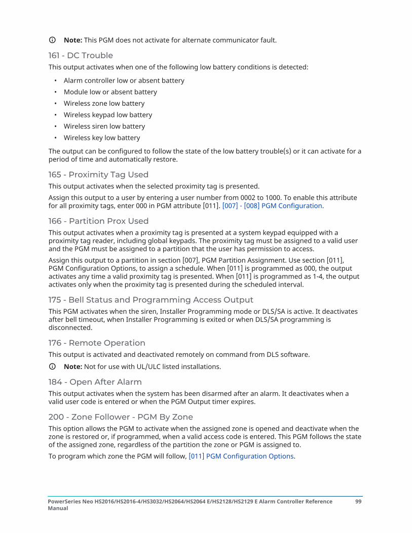
Note: This PGM does not activate for alternate communicator fault.
161 - DC TroubleThis output activates when one of the following low battery conditions is detected:
• Alarm controller low or absent battery• Module low or absent battery• Wireless zone low battery• Wireless keypad low battery• Wireless siren low battery• Wireless key low battery
The output can be configured to follow the state of the low battery trouble(s) or it can activate for aperiod of time and automatically restore.
165 - Proximity Tag UsedThis output activates when the selected proximity tag is presented.Assign this output to a user by entering a user number from 0002 to 1000. To enable this attributefor all proximity tags, enter 000 in PGM attribute [011]. [007] - [008] PGM Configuration.
166 - Partition Prox UsedThis output activates when a proximity tag is presented at a system keypad equipped with aproximity tag reader, including global keypads. The proximity tag must be assigned to a valid userand the PGM must be assigned to a partition that the user has permission to access.Assign this output to a partition in section [007], PGM Partition Assignment. Use section [011],PGM Configuration Options, to assign a schedule. When [011] is programmed as 000, the outputactivates any time a valid proximity tag is presented. When [011] is programmed as 1-4, the outputactivates only when the proximity tag is presented during the scheduled interval.
175 - Bell Status and Programming Access OutputThis PGM activates when the siren, Installer Programming mode or DLS/SA is active. It deactivatesafter bell timeout, when Installer Programming is exited or when DLS/SA programming isdisconnected.
176 - Remote OperationThis output is activated and deactivated remotely on command from DLS software.
Note: Not for use with UL/ULC listed installations.
184 - Open After AlarmThis output activates when the system has been disarmed after an alarm. It deactivates when avalid user code is entered or when the PGM Output timer expires.
200 - Zone Follower - PGM By ZoneThis option allows the PGM to activate when the assigned zone is opened and deactivate when thezone is restored or, if programmed, when a valid access code is entered. This PGM follows the stateof the assigned zone, regardless of the partition the zone or PGM is assigned to.To program which zone the PGM will follow, [011] PGM Configuration Options.
99PowerSeries Neo HS2016/HS2016-4/HS3032/HS2064/HS2064 E/HS2128/HS2129 E Alarm Controller ReferenceManual

201-216 – Zone Follower (Zones 1-128)This output type is assigned to a group of zones and is normally activated, but deactivates when azone is tripped. Zones are assigned to this output in the following groups:
201 – Zones 1-8 209 – Zones 65-72202 – Zones 9-16 210 – Zones 73-80203 – Zones 17-24 211 – Zones 81-88204 – Zones 25-32 212 – Zones 89-96205 – Zones 33-40 213 – Zones 97-104206 – Zones 41-48 214 – Zones 105-112207 – Zones 49-56 215 – Zones 113-120208 – Zones 57-64 216 – Zones 121-128
If multiple zones are enabled, any active zone in that group triggers the output. The PGM will notactivate again until all zones are restored.
[010] PGM AttributesThe following options are used to program the operating characteristics of the main bell and PGMoutputs.
[000] Main Bell MaskThis programming section is used to configure the types of audible alarms that trigger the mainbell output on the alarm controller. All options are selected by default.
Fire AlarmON: Fire alarm ([F] key, Fire zones) activates the main siren.OFF: Fire alarm does not activate the main siren.
CO AlarmON: CO alarm activates the main siren.OFF: CO alarm does not activate the main siren.
Burglary AlarmON: Burglary alarm (Delay, Instant, Interior, Stay/Away, Night, Interior Delay, Instant Stay/Away,Day, 24-hour Burglary) activates the main siren.OFF: Burglary alarm does not activate the main siren.
24-Hour Flood AlarmON: Main bell activates in the event of a 24-Hour Flood alarm.OFF: Main bell does not activate in the event of a 24-Hour Flood alarm.
Bell SquawksON: Squawks activate the main siren. Bell squawks must be enabled to use the following options:
• Bell Squawk on arm (single)• Bell Squawk on disarm (double)• Bell Duration Auto-Arm (single every second)• Bell Squawk on Exit (single every second)
PowerSeries Neo HS2016/HS2016-4/HS3032/HS2064/HS2064 E/HS2128/HS2129 E Alarm Controller ReferenceManual
100

• Bell Squawk on Entry (single every second)• Bell Squawk on Trouble (single every 10 seconds)
OFF: Squawks do not activate the main siren.
[001]-[164] PGM 001-164 AttributesThe following PGM attributes can be assigned to a PGM. Each attribute has various toggle options,depending on the PGM type selected (section [009]).
101 - Fire and Burglary
01 - True Output/InvertedON: deactivated during normal operation. Activated when triggered.OFF: active during normal operation. Deactivated when triggered.
102 - Delay Fire and Burglary
01 -True Output/InvertedON: deactivated during normal operation. Activated when triggered.OFF: active during normal operation. Deactivated when triggered.
103 - Sensor Reset [*][7][2]
01 - True Output/InvertedON: deactivated during normal operation. Activated when triggered.OFF: active during normal operation. Deactivated when triggered.
03 - Access Code Required / No Code RequiredON: Access code required for activationOFF: No access code required for activation
109 - Courtesy Pulse
01 - True Output/InvertedON: deactivated during normal operation. Activated when triggered.OFF: active during normal operation. Deactivated when triggered.
111 - Keypad Buzzer Follow
01 - True Output/InvertedON: deactivated during normal operation, activated when triggered.OFF: activated during normal operation, deactivated when triggered.
02 - Timed OutputON: output remains active until the PGM output timer expires.OFF: output remains active until the buzzer condition ends.
09 - Entry DelayON: activates on entry delay.OFF: does not activate on entry.
10 - Exit DelayON: activates on exit delay.
101PowerSeries Neo HS2016/HS2016-4/HS3032/HS2064/HS2064 E/HS2128/HS2129 E Alarm Controller ReferenceManual

OFF: does not activate on exit delay.
11 - Door ChimeON: activates when chime is enabled.OFF: does not activate when chime is enabled.
12 - Keypad Buzzer ZoneON: activates when keypad buzzer goes into alarm.OFF: does not activate when keypad buzzer goes into alarm.
13 - Audible Exit FaultON: activates when audible exit fault pre-alert begins.OFF: does not activate when audible exit fault pre-alert begins.
14 - Auto-Arm Pre-AlertON: activates when auto-arming pre-alert begins.OFF: does not activate when auto-arming pre-alert begins.
114 - Ready To Arm
True Output/InvertedON: deactivated during normal operation. Activated when triggered.OFF: active during normal operation. Deactivated when triggered.
115 - Armed Status
01 - True Output/InvertedON: deactivated during normal operation. Activated when triggered.OFF: active during normal operation. Deactivated when triggered.
116 - Armed Away Mode
01 - True Output/InvertedON: deactivated during normal operation. Activated when triggered.OFF: active during normal operation. Deactivated when triggered.
117 - Armed Stay Mode
01 - True Output/InvertedON: deactivated during normal operation. Activated when triggered.OFF: active during normal operation. Deactivated when triggered.
121-124 – Command Output 1-4
01 - True Output/InvertedON: deactivated during normal operation, activated when triggered.OFF: activated during normal operation, deactivated when triggered.
02 - Timed Output / Latched OutputON: output remains active until the PGM output timer expires.OFF: output remains active until an access code has been entered.
PowerSeries Neo HS2016/HS2016-4/HS3032/HS2064/HS2064 E/HS2128/HS2129 E Alarm Controller ReferenceManual
102

03 - Access Code Required / No Code RequiredON: access code required for activation.OFF: no access code required for activation.
129 - Partition Status Alarm Memory
01 - True Output/InvertedON: deactivated during normal operation. Activated when triggered.OFF: active during normal operation. Deactivated when triggered.
132 - Holdup Output
01 - True Output/InvertedON: deactivated during normal operation. Activated when triggered.OFF: active during normal operation. Deactivated when triggered.
146 - TLM Alarm
01 - True Output/InvertedON: deactivated during normal operation. Activated when triggered.OFF: active during normal operation. Deactivated when triggered.
147 - Kissoff Output
01 - True Output/InvertedON: deactivated during normal operation. Activated when triggered.OFF: active during normal operation. Deactivated when triggered.
148 - Ground Start
01 - True Output/InvertedON: deactivated during normal operation. Activated when triggered.OFF: active during normal operation. Deactivated when triggered.
149 - Alternate Communicator
01 - True Output/InvertedON: deactivated during normal operation, activated when triggered.OFF: activated during normal operation, deactivated when triggered.
02 - Timed Output / Latched OutputON: output remains active until the PGM output timer expires.OFF: output remains active until an access code has been entered.
04 - Fire alarm
WARNING: If the fire alarm sounds, follow your emergency evacuation plan immediately.
05 - Panic AlarmON: activates with panic alarm, [P] key, panic zones.OFF: does not activate with panic alarm.
06 - Burglary AlarmON: activates with burglary alarm.
103PowerSeries Neo HS2016/HS2016-4/HS3032/HS2064/HS2064 E/HS2128/HS2129 E Alarm Controller ReferenceManual

OFF: does not activate with burglary alarm.
07 - Open/CloseON: activates with opening or closing.OFF: does not activate with opening or closing.
08 - Zone Auto-BypassON: activates when a zone is automatically bypassed.OFF: does not activate when a zone is automatically bypassed.
09 - Medical AlarmON: activates with medical alarm, [+] key, medical zones.OFF: does not activate with medical alarm.
10 - Burglary VerifiedON: activates with burglary verified alarm (or police code).OFF: does not activate with burglary verified alarm.
11 - Open After AlarmON: activates when the system is disarmed with an alarm in memory.OFF: does not activate when the system is disarmed with an alarm in memory.
12 - Emergency AlarmON: activates with zone emergency alarm.OFF: does not activate with zone emergency alarm.
13 - Duress AlarmON: activates with duress alarm.OFF: does not activate with duress alarm.
14 - Hold Up verifiedON: activates when a verified holdup event is detected.OFF: does not activate when a verified holdup event is detected.
155 - System Trouble
01 - True Output/InvertedON: deactivated during normal operation, activated when triggered.OFF: activated during normal operation, deactivated when triggered.
02 - Timed Output / Latched OutputON: output remains active until the PGM output timer expires.OFF: output remains active until an access code has been entered.
04 - Service RequiredON: activates on service required trouble condition.OFF: does not activate on service required trouble condition.
05 - Loss of ClockON: activates on loss of clock trouble condition.OFF: does not activate on loss of clock trouble condition.
PowerSeries Neo HS2016/HS2016-4/HS3032/HS2064/HS2064 E/HS2128/HS2129 E Alarm Controller ReferenceManual
104

06 - DC TroubleON: activates if a panel low or no battery trouble is detected, or if an HSM2204/2300 1-4 low or nobattery trouble is detected.OFF: does not activate on DC Trouble condition.
07 - Bus VoltageON: activates when a system module has measured a low Aux voltage.OFF: does not activate for a module low voltage trouble.
08 - AC TroubleON: activates when any system device detects an AC Failure condition.OFF: does not activate for AC Failure conditions.
09 - Device FaultON: activates if one of the following device fault conditions is present:
• zone 001 – 128 fault• keypad 01 – 16 fault• siren 01 – 16 fault• repeater 01 – 08 fault• fire trouble• CO trouble• gas trouble• heat trouble• freeze trouble• probe disconnected trouble• self test trouble
OFF: does not activate if a device fault condition is present.
10 - Device Low BatteryON: activates if any of the following device low battery conditions is present:
• zone 001 – 128• keypad 01 – 16• siren 01 – 16• repeater 01 – 08• user 01 – 32 (wireless keys)
OFF: does not activate if a device low battery condition is present.
11 - Device TamperON: activates if any of the following device tamper conditions is present:
• zone 001 – 128• keypad 01 – 16• siren 01 – 16• repeater 01 – 08
105PowerSeries Neo HS2016/HS2016-4/HS3032/HS2064/HS2064 E/HS2128/HS2129 E Alarm Controller ReferenceManual

OFF – does not activate if a device tamper condition is present.
12 - RF DelinquencyON: activates if any of the following RF delinquency troubles is detected:
• zone 001 – 128• keypad 01 – 16• siren 01 – 16• repeater 01 – 08
OFF – does not activate if an RF delinquency condition is present.
13 - Module SupervisoryON – activates if any of the following module supervisory troubles is detected:
• HSM2HOST• keypad 01 – 16• zone expander 01 – 15• HSM2204 1 – 4• HSM2300 1 – 4• HSM2208 01 – 16
OFF – does not activate if a module supervisory trouble is detected.
14 - Module TamperON – activates if any of the following module tamper conditions is present:
• HSM2HOST• Keypad 01 – 16• Zone expander 01 – 15• HSM2204 1 – 4• HSM2300 1 – 4• HSM2208 01 – 16 tamper troubles
OFF – does not activate if a module tamper condition is present.
15 - CommunicationsON – activates if any of the following communications conditions is present:
• TLM trouble• FTC receiver 1 – 4• SIM Lock trouble• Cellular Trouble• Ethernet Trouble• Receiver 1 – 4 absent• Receiver 1 – 4 supervision trouble• SMS Configuration trouble• Alt comm. Fault.
PowerSeries Neo HS2016/HS2016-4/HS3032/HS2064/HS2064 E/HS2128/HS2129 E Alarm Controller ReferenceManual
106

OFF – does not activate if a communications trouble condition is present.
16 - Not NetworkedON – activates if any of the following not networked conditions is present:
• Zone 001 – 128• Keypad 01 – 16• Siren 01 – 16• Repeater 01 – 08• User 01 – 1000 (wireless keys) not networked troubles
OFF – does not activate if a not networked trouble condition is present.
156 - Latched System Event
01 - True Output/InvertedON: deactivated during normal operation. Activated when triggered.OFF: activated during normal operation. Deactivated when triggered.
02 - Timed Output / Latched OutputON: output remains active until the PGM output timer expires.OFF: output remains active until an access code has been entered.
04 - Fire AlarmON: activates with fire alarm, [F] key, fire zones, 2-wire smoke.OFF: does not activate with fire alarm.
05 - Panic AlarmON: activates on panic alarm (audible or silent).OFF: does not activate on panic alarm.
06 - Burglary AlarmON: activates on burglary alarm.OFF: does not activate on burglary alarm.
07 - Medical AlarmON: activates on medical alarm.OFF: does not activate on medical alarm.
08 - SupervisoryON: activates on supervisory alarm.OFF: does not activate on supervisory alarm.
09 - Priority EventON: activates on priority alarm.OFF: does not activate on priority alarm.
10 - HoldupON: activates on holdup alarm.OFF: does not activate on Holdup alarm.
107PowerSeries Neo HS2016/HS2016-4/HS3032/HS2064/HS2064 E/HS2128/HS2129 E Alarm Controller ReferenceManual

11 - Duress AlarmON: activates on duress alarm.OFF: does not activate on duress alarm.
12 - Emergency AlarmON: activates on emergency alarm.OFF: does not activate on emergency alarm.
13 - Fire SupervisoryON: activates on fire supervisory alarm.OFF: does not activate on fire supervisory alarm.
14 - Fire TroubleON: activates on fire trouble condition.OFF: does not activate on fire trouble condition.
15 – CO AlarmON: activates on CO alarm.OFF: does not activate on CO alarm.
157 - System Tamper
01 - True Output/InvertedON: deactivated during normal operation. Activated when triggered.OFF: activated during normal operation. Deactivated when triggered.
09 - System/Module TampersON: activates when any module tamper condition occurs.OFF: does not activate when any module tamper condition occurs.
10 - Zone TampersON: activates when any zone tamper condition occurs.OFF: does not activate when zone tamper conditions occur.
161 - DC Trouble
01 - True Output/InvertedON: deactivated during normal operation. Activated when triggered.OFF: activated during normal operation. Deactivated when triggered.
02 - PGM TimerON: output remains active until an access code is entered or certain criteria have been met,depending on the PGM type.OFF: output remains active until the PGM output timer expires.
09 - Battery LowON: activates when a low battery trouble occurs.OFF: does not activate when a low battery trouble occurs.
10 - Battery AbsentON: activates when a battery absent trouble occurs.
PowerSeries Neo HS2016/HS2016-4/HS3032/HS2064/HS2064 E/HS2128/HS2129 E Alarm Controller ReferenceManual
108
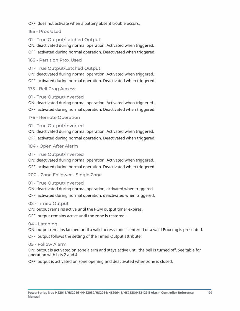
OFF: does not activate when a battery absent trouble occurs.
165 - Prox Used
01 - True Output/Latched OutputON: deactivated during normal operation. Activated when triggered.OFF: activated during normal operation. Deactivated when triggered.
166 - Partition Prox Used
01 - True Output/Latched OutputON: deactivated during normal operation. Activated when triggered.OFF: activated during normal operation. Deactivated when triggered.
175 - Bell Prog Access
01 - True Output/InvertedON: deactivated during normal operation. Activated when triggered.OFF: activated during normal operation. Deactivated when triggered.
176 - Remote Operation
01 - True Output/InvertedON: deactivated during normal operation. Activated when triggered.OFF: activated during normal operation. Deactivated when triggered.
184 - Open After Alarm
01 - True Output/InvertedON: deactivated during normal operation. Activated when triggered.OFF: activated during normal operation. Deactivated when triggered.
200 - Zone Follower - Single Zone
01 - True Output/InvertedON: deactivated during normal operation, activated when triggered.OFF: activated during normal operation, deactivated when triggered.
02 - Timed OutputON: output remains active until the PGM output timer expires.OFF: output remains active until the zone is restored.
04 - LatchingON: output remains latched until a valid access code is entered or a valid Prox tag is presented.OFF: output follows the setting of the Timed Output attribute.
05 - Follow AlarmON: output is activated on zone alarm and stays active until the bell is turned off. See table foroperation with bits 2 and 4.OFF: output is activated on zone opening and deactivated when zone is closed.
109PowerSeries Neo HS2016/HS2016-4/HS3032/HS2064/HS2064 E/HS2128/HS2129 E Alarm Controller ReferenceManual

Timed Output Latching Follow Alarm PGM OutputOFF OFF OFF ON upon zone opening
(including tamper andfault), OFF upon zoneclosing
OFF OFF ON ON upon zone alarm,OFF upon bell cut-offor alarm silenced
OFF ON OFF ON upon zoneopening, OFF uponvalid code
OFF ON ON ON upon zone alarm,OFF upon valid code
ON OFF OFF ON upon zoneopening, OFF uponPGM timer expires
ON OFF ON ON upon zone alarm,OFF upon PGM timerexpires
ON ON OFF ON upon zoneopening, OFF uponvalid code
ON ON ON ON upon zone alarm,OFF upon valid code
201 - 216 Zone Follower Zones 1-128
01 - True Output/InvertedON: deactivated during normal operation. Activated when triggered.OFF: activated during normal operation. Deactivated when triggered.
02 - Timed OutputON: output remains active until the PGM output timer expires.OFF: output remains active until an access code has been entered.
09-16 – Zone Terminals 1-8ON: zones associated with terminals 1-8 are enabled for zone follower operation.OFF: zones are not enabled for zone follower operation.
[011] PGM Configuration OptionsThis section is used to configure PGM types that offer multiple options.
[001]-[164] Select PGMThe following options may be selected for each PGM:
Zone Follow PGM By ZoneThis option is used to specify the zone that PGM type 200 follows. Enter 001-128 to select zone1-128.
PowerSeries Neo HS2016/HS2016-4/HS3032/HS2064/HS2064 E/HS2128/HS2129 E Alarm Controller ReferenceManual
110

Proximity Tag UsedThis option is used to define which proximity tag will activate PGM outputs programmed as [165]Prox Used. Enter 000 to enable this PGM attribute for all user proximity tags, or enter user number0002-1000 to have this attribute activated by a specific user proximity tag.
Command Output 1-4This option is used to assign a schedule, programmed in section [601]-[604], for the commandoutput PGMs to follow. Program 001-004 to for schedules 1-4. Program 000 to activate the PGMwhen a proximity tag is presented.
[012] System Lockout
Keypad Lockout – Number of Invalid Local AttemptsThis option controls the number of invalid access code entries allowed before the keypad is locked.When keypad lockout occurs, the system is inaccessible by keypad for the programmed duration. Ifthe number of invalid attempts is not reached within one hour, or if a valid access code is entered,the counter is reset to 0. Valid entries are 000 to 255 minutes. Entering 000 disables the feature.Presenting an invalid tag counts toward keypad lockout.
Note: For EN 50131 certified installations, maximum number of attempts is 10.
Keypad Lockout DurationThis programming option determines the length of time the keypad is locked out for. If the systemcold starts while in keypad lockout, the lockout is removed. Valid entries are 000 to 255 minutes.Entering 000 disables keypad lockout.
Note: For EN 50131 certified installations, minimum of duration is 2 minutes.
Remote Lockout DLSThis programming option determines the number of invalid access code entries allowed via SMS orDLS before remote access is locked out for the programmed duration (see below). If the number ofinvalid attempts is not reached within one hour, or if a valid access code is entered through SMS orDLS, the counter is reset to 0. The valid entries are 003 to 255 attempts. Default is 6 attempts. Thenumber of invalid attempts is fixed at 5 when using System Administrator Software and the lockoutduration is 1 hour.
Note: DLS tries to connect using the programmed DLS Access code first and, ifunsuccessful, using the default DLS access code. Two failed attempts are counted if both codesare incorrect.
Remote Lockout DurationThis programming option determines how long the remote lockout lasts. If the system cold startswhile in remote lockout, the lockout restarts for the programmed duration. Valid entries are 001 to255 minutes. Entering 000 disables remote lockout.
System Options
[013] System Option 1
1 - NC Loop/EOLON: All zones are wired as normally closed circuits with returns connected to a COM terminal. Theend-of-line resistor is not required. An alarm is generated when the circuit is opened.
111PowerSeries Neo HS2016/HS2016-4/HS3032/HS2064/HS2064 E/HS2128/HS2129 E Alarm Controller ReferenceManual

OFF: All zones must be wired with an end-of-line resistor configuration, determined by option 2below.
Note: The valid EOL value is 5600 Ohms (5.6KΩ).
2 - DEOL/SEOLON: All zones use Double-End-of-Line resistors, except Standard Fire, Delayed Fire, Auto-VerifiedFire, Co and Supervisory zone types. DEOL resistors enable detection of zone faults and tampers.The tamper resistor (5.6KΩ) is placed in parallel across the alarm activating device, and the singleEOL resistor (5.6KΩ) is placed between the alarm and tamper contacts.This allows detection of zone faults (shorted zone), tampers (open zone), alarms (11.2KΩ), andrestored zones (5.6KΩ).If the zone is disarmed and placed in the tamper or fault state, trouble beeps sound on all systemkeypads until a key is pressed on each partition. A zone tamper is sent to the monitoring station ifprogrammed. If the zone is armed and a tamper is activated, the tamper alarm and zone alarm arelogged and transmitted.OFF: All zones must have a 5.6KΩ resistor. If the zone is shorted or open, it is in the tripped state. Ifthe zone is open and programmed as a fire zone, it is in the trouble state. The EOL and DEOL zoneattributes override this system option.
Note: Zone Faults (Supervisories) on wireless zones do not cause an audible alarm whilearmed.
3 - Show All Troubles When ArmedON: The Trouble LED illuminates when troubles are present on the system in both the armed anddisarmed state.OFF: The Trouble LED illuminates for all troubles while disarmed, but only for Fire Troubles whilearmed.
4 - Tamper/Faults Do Not Show As OpenON: The zone LED does not illuminate if the zone is in the tamper or fault states. Only the TroubleLED illuminates.OFF: The respective zone LED illuminates if the zone is in the tamper or fault states. The TroubleLED also illuminates.
5 - Auto-Arm Schedule in [*][6]ON: The auto-arm schedules ([151] - [158]) are accessible to installers via [*][6] as well as InstallerProgramming.OFF: The auto-arm schedules ([151] - [158]) are only accessible to installers via InstallerProgramming.
Note: This toggle controls access for all eight partitions.
6 - Audible Exit FaultON: If a delay type zone is violated after the exit delay has expired, an entry delay warning issounded through the keypad and siren indicating that an improper exit was made. If the alarmsystem is disarmed within the entry delay period no signal is sent.OFF: The entry delay warning is sounded only through the keypad.
7 - Event Buffer Follows SwingerON: Once an event reaches its swinger shutdown limit programmed in [377] CommunicationVariables, it will no longer log events to the event buffer until the swinger shutdown is reset. Thisavoids filling the event buffer with false events.
PowerSeries Neo HS2016/HS2016-4/HS3032/HS2064/HS2064 E/HS2128/HS2129 E Alarm Controller ReferenceManual
112

OFF: The event buffer continues to log events to the buffer even after the event has gone intoswinger shutdown.
8 - Temporal Three Fire SignalingON: All fire bells sound in the temporal three pattern. Cadence is as follows: (500ms ON, 500msOFF, 500ms ON, 500ms OFF, 500ms ON, 1.5 sec. OFF).OFF: All fire bells will sound with the standard 1 second on/1 second off fire bell cadence.
Note: Must be on for UL/ULC installations.
[014] System Option 2
Bell SquawkON: The siren emits a single squawk when armed in any manner, including Auto-arm, and a doublesquawk when disarmed.When the system is disarmed, the siren emits a series of three squawk pairs to indicate alarms inmemory.OFF: The siren does not squawk when arming or disarming.
Note: For UL/ULC, must be enabled if wireless keys are used with the alarm system.
2 - Bell Squawk on Auto-ArmON: The siren squawks once every 10 seconds during the auto-arm pre-alert time.OFF: The siren does not squawk during auto-arm pre-alert.
3 - Bell Squawk On ExitON: The siren squawks once per second during exit delay, changing to 3 squawks per second forthe final 10 seconds.OFF: The siren does not squawk for exit delay conditions.
4 - Bell Squawk On EntryON: The siren pulses with the same timing as the keypad buzzer during entry delay, changing to 3squawks per second for the final 10 seconds.OFF: The siren does not activate during entry delay.
4 - Bell Squawk On TroubleON: When a trouble condition exists on the system, the siren squawks 2 times every 10 seconds (asper the keypad buzzer).The siren is silenced when the keypad beeps are silenced (any key pressed on keypad).OFF: The siren does not activate with a trouble condition.
6 - Not Used
7 - Exit Delay TerminationON: The exit delay is reduced to 5 seconds once a Delay 1 zone is restored. Force-Arm Delay 1 typezones also end the exit delay.OFF: The exit delay timer continues to count even after the delay zone is restored.All audible options associated with the exit delay function are silenced until the time programmedfor the exit delay has elapsed.
113PowerSeries Neo HS2016/HS2016-4/HS3032/HS2064/HS2064 E/HS2128/HS2129 E Alarm Controller ReferenceManual

8 - Fire Bell ContinuesON: For all Fire type alarms, the siren sounds until an access code is entered to silence the alarm ordisarm the system regardless of the time programmed for bell timeout.OFF: For all Fire type alarms, the siren sounds for the length of Bell Timeout or until an access codeis entered.
Note: Must be disabled for ULC installations.
[015] System Option 3
1 - [F] Key EnabledON: Pressing and holding the [F] key for 2 seconds triggers a Fire alarm.OFF: The [F] key does not sound or report an alarm when pressed.
Note: Use only for residential fire installations.
2 - [P] Key EnabledON: When a valid [P] key alarm is generated, the keypad buzzer emits a series of 3 beeps toacknowledge the alarm and the siren sounds for the length of bell timeout.OFF: When a valid [P] key alarm is generated, the keypad buzzer and the siren are silent, but thealarm is still transmitted (if programmed).
Note: Fire, Medical, and Panic key transmissions follow the partition 1 alarm/restore calldirection options (Fire, Medical, and Panic key). The Fire, Medical, Panic keys operate even ifkeypad blanking and keypad lockout are active.
3 - Quick ExitON: When the system is armed, users may enter the [*][0] command to temporarily bypass a singleDelay 1 or Delay 2 zone to exit the premises. Only one delay zone may be activated. Activity onanother delay zone initiates the appropriate alarm sequence. If the delay zone is still open twominutes after the [*][0] command is entered, entry delay is initiated. If armed in the Stay mode, theautomatic bypass on Stay/Away zones remains.OFF: When the system is armed, users can not perform a quick exit using [*][0].
4 - Quick Arming /Function KeyON: [*][0] arming and Stay/Away function keys may be used to arm the system without the entry ofa valid access code.OFF: [*][0] arming is not permitted. All arming functions require the entry of an access code toactivate (including Stay/Away keys).
5 - Not Used
6 - Master Code Not User ChangeableON: The master code (access code 01) may not be changed by the user and may only beprogrammed in Installer Programming.OFF: The master code may be programmed by the user using the [*][5][Master Code] command.The master code may also be programmed in Installer Programming.
7 - Telephone Line Monitor EnableON: The TLM function is active and the system indicates a trouble condition when using the [*][2]View Trouble Conditions command.OFF: The TLM function is deactivated and telephone line troubles are not indicated by the system.
Note: Must be ON for UL/ULC listed installations.
PowerSeries Neo HS2016/HS2016-4/HS3032/HS2064/HS2064 E/HS2128/HS2129 E Alarm Controller ReferenceManual
114

8 - Telephone Line Monitor Audible When ArmedON: When the system is disarmed, a telephone line monitor trouble generates a trouble indicationas described above. If the system is armed, a telephone line monitor trouble generates an audiblealarm on the siren for the duration programmed for bell timeout or until an access code is enteredto disarm.OFF: Telephone line troubles generate a trouble indication, the Trouble LED illuminates, and thekeypad buzzer beeps until a key is pressed.
[016] System Option 4
1 - AC Trouble DisplayON: If AC power fails, the condition is reported to the monitoring station and is indicated as atrouble condition on the system keypads.OFF: If AC power fails, the condition is reported, but the Trouble light on the system keypads is off.The trouble is displayed in [*][2].
Note: Must be ON for UL/ULC listed installations.
2 - AC Trouble Light FlashesON: When AC power is lost, the Trouble light flashes in the base “Ready” and “Armed” mode within30 seconds of power loss. When AC restores, the Trouble light stops flashing within 30 seconds. Ifenabled, this option overrides the AC display option.OFF: When AC power is lost, the Trouble light illuminates but does not flash.
5 - Keypad BlankingON: If no keys are pressed for 30 seconds, all keypad lights except backlighting (if enabled) are shutoff until the next keypress, entry delay, audible alarm or keypad buzzer condition.Keypad function keys still operate when the keypad is blank, unless the function key is programmedto require an access code. Keypad Blanking While Armed overrides this feature. When a partitionis armed and in alarm, entering a code to remove blanking silences the alarm and disarms thesystem.OFF: The keypad lights remain ON at all times.
4 - Keypad Blanking Requires CodeON: A valid access code must be entered before a blanked keypad can be used. Informationbecomes inaccessible to level 1 users.OFF: Pressing any key on a blanked keypad removes keypad blanking.
Note: Keypad Blanking Requires Code must be set to off for CP-01 listed installations.
5 - Keypad BacklightingON: All keypads on the system have backlighting on at all times.OFF: All keypads on the system have backlighting off.
6 - Power Save ModeON: If AC power fails, all keypad lights including backlighting are shut OFF. The keypad lights comeback ON after a keypress, entry delay, audible alarm or keypad buzzer condition (except doorchime). Keypad lights return to the off state after 30 seconds of inactivity.OFF: If AC power fails, keypads do not go into power save mode.
7 - Bypass Display When ArmedON: The Bypass status light is on if zones are bypassed when the system is armed.
115PowerSeries Neo HS2016/HS2016-4/HS3032/HS2064/HS2064 E/HS2128/HS2129 E Alarm Controller ReferenceManual

OFF: The Bypass light is on only while the system is disarmed to indicate that zones on the systemare bypassed. When the system is armed, the Bypass light is off.The Bypass status light is on if Stay/Away zones are auto bypassed at the time of arming regardlessof whether or not this option is enabled. This option only enables and disables manual bypassdisplay.
8 - Keypad Tampers EnabledON: All keypads containing tamper switches generate tamper alarms and restores.OFF: The tamper switches on all keypads do not generate tamper alarms.
Note: If this option is used, all keypads should be properly installed and secured (tamperrestored) before enabling the option.
Note: Must be ON for UL/ULC commercial burglary listed installations.
[017] System Option 5
1 - Chime on OpeningON: When a zone with the door chime attribute ON is opened, the system keypads and sirensbeeps.OFF: When a zone with the door chime attribute ON is opened, the system keypads and sirens donot beep.
2 - Chime on ClosingON: When a zone with the door chime attribute ON is closed, the system keypads and sirens (ifenabled) beep.OFF: When a zone with the door chime attribute ON is closed, the system keypads and sirens (ifenabled) do not beep.
3 - RF Jam Trouble BeepsON: Trouble beeps sound when an RF Jam Trouble is detectedOFF: Trouble beeps do not sound when an RF Jam Trouble is detected
4 - Multi HitON: Alarms from the same zone within the Burglary Verification Timer duration cause the policecode or burglary verified to be logged and transmitted. The number of zone trips required to createa confirmed alarm depends on the value of the programmable burglary verification counter.OFF: Alarms from the same zone within the Burglary Verification Timer duration do not cause thepolice code or burglary verified to be logged and transmitted.
Note: This feature only applies to zones defined as Interior, Interior Delay, Interior Stay/Away,Instant Stay/Away, Delay Stay/Away, or Night Zones (PIR Zones). Do not enable this option ifsection [380], option 2 - Restore on Bell Time Out is enabled.
5 - Late to CloseON: Provides an audible warning if the alarm system has not been armed by a programmed time ofday but does not arm the alarm system. The alarm system communicates and logs a Late to Closeevent at the end of the Auto-arm/Postpone pre-alert for each partition.OFF: The alarm system will neither communicate nor log a Late to Close event at the timeprogrammed for Auto-arm for each partition.
PowerSeries Neo HS2016/HS2016-4/HS3032/HS2064/HS2064 E/HS2128/HS2129 E Alarm Controller ReferenceManual
116

Note: If the Auto-arm toggle option is disabled, the Auto-arm Pre-alert still occurs when atime is programmed for that day (if enabled) and the event is logged and communicated. Thisoption does not directly affect the functionality of Auto-arm. If Late to Close is enabled andAuto-arming is not, LCD keypads display “System Arming in Progress” during the Late to ClosePre-alert.
6 - Daylight Savings TimeON: The alarm system adjusts between Daylight and Standard times according to the timesprogrammed in System Timers ([005] options 001-002).
Note: Auto-arm and Test Transmissions should not be attempted between 0200 and 0300hours, as they will be missed during a daylight savings clock adjust. Events programmed tooccur between 0100 and 0200 will occur twice during a daylight savings clock adjust. DaylightSavings Time programming should not conflict with the Auto-arm and Test Transmissionsprogramming.
OFF: The alarm system makes no automatic time adjustments for Daylight Saving time.
7 - Silence Chime During Quick Exit DelayON: Door chime does not sound during quick exit.OFF: Door chime sounds during quick exit, according to zone settings.
8 - Bell Squawk on Away Arm/ Disarm OnlyON: Bell Squawks are only heard when away arming, as well as when disarming from Away mode.This feature prevents the siren from activating when arming in stay and night modes.OFF: Bell Squawks are heard during all types of arming and disarming.
Note: This option follows the “Bell Squawk Attribute” features if they are enabled.
[018] System Option 6
1 - Test Transmission ExceptionON: The alarm system does not send a test transmission if a transmission was sent to the receiverwithin the programmed interval as set in section [377]>[003] – Periodic Test Transmission Cycle.OFF: Test transmissions are always sent at the programmed interval.
2 - Real-Time Bypass ReportingON: When a non-24-hour zone is bypassed in [*][1], the system immediately logs andcommunicates the bypass status of the zone.Global Zones: 24-hour and non-24 hour zone bypasses are logged and communicated in real time.Non-24 hour zone unbypass events are generated when the last assigned partition is disarmed.OFF: When a non 24-hour zone is bypassed in [*][1], the system logs and communicates the bypassstatus of the zone only after the partition is armed. This option is applied regardless of how zonesare bypassed in [*][1], recall bypass group, clear all bypasses, bypass open zones, bypass recall aswell as other methods such as bypassing via ITv2 or DLS.Global Zones: 24-hour zone bypasses are logged and communicated in real time. Non 24-hour zonebypass events are logged and communicated when armed. Non 24-hour zone unbypass events arelogged and communicated when the last partition is disarmed.
3 - Armed Status PGM ON at End of Exit DelayON: PGMs are activated at the end of exit delay. This applies to PGMs with one of the followingarmed status attributes:
• System Armed Status PGM
117PowerSeries Neo HS2016/HS2016-4/HS3032/HS2064/HS2064 E/HS2128/HS2129 E Alarm Controller ReferenceManual

• Away Armed Status PGM• Stay Armed Status PGM• Away Armed with No Zone Bypass Status• Partition Status Alarm Memory
OFF: PGMs are activated at the beginning of exit delay. This applies to PGMs with one of the armedstatus attributes listed above.
4 - Not Used
5 - Keypad Buzzer Follows BellON: The keypad buzzer activates with all bell activity for the selected partition.OFF: The keypad buzzer only activates with alarms programmed to do so.
6 - Not Used
7 - Exit Delay RestartON: Opening a delay zone door after it has already been opened and closed during an exit delayrestarts the exit delay timer. Further openings and closings do not restart the timer.OFF: Delay zone openings and closings do not restart the exit delay.
8 - AC Fail Trouble BeepsON: System keypads beep when an AC trouble event occurs.OFF: System keypads are silent during AC troubles.
[019] System Option 7
1 - Audible Wireless Device FaultON: If a wireless zone fault occurs while armed, the siren sounds for the duration of Bell Time Out.This option only affects zone definitions that are considered armed. The following zone types donot generate an alarm when faulted while stay armed: interior stay away zone, delay stay awayzone, instant stay away zone, night zone. The following zone types do not generate an audiblealarm in any armed state (stay, away, or night): 24-hour supervisory, 24-hour non-alarm, 24-hourCO, delayed 24-hour Fire, standard 24-hour fire, Auto-verified fire.When the partition is armed, wireless supervisory troubles from sirens, keypads and repeatersgenerate audible alarm conditions.If Tamper/Fault Detection is enabled, these events can start the burglary verified timer and affectthe burglary verified counter.OFF: Wireless device faults do not sound the siren.
2 - Latching TroublesON: Troubles remain on the system until viewed via [*][2], even if they are restored. The troublecondition is cleared when the [#] key is pressed from the [*][2] menu after the trouble has restored.The Trouble LED turns off unless other troubles are present. The trouble is not cleared if the [*][2]menu times out before the [#] key is pressed.OFF: Troubles are cleared once restored.
Note: For UL installations, this option must be ON.
PowerSeries Neo HS2016/HS2016-4/HS3032/HS2064/HS2064 E/HS2128/HS2129 E Alarm Controller ReferenceManual
118

3 - Not Used
4 - R ButtonON: When the panel goes off hook to communicate, it performs a dial tone check. If no dialtone isdetected, the panel will wait 20 seconds and perform another 5 second dial tone search. If dial toneis still not present, the panel force dials if programmed to do so. This entire sequence counts as onedialing attempt.OFF: If no dial tone is present, the panel does not attempt to switch to a second phone line.
5 - Audible Bus FaultON: All module supervisory trouble conditions activate the siren.OFF: Only zone expander supervisory trouble conditions while armed activate the siren.
6 - Duress CodesON: The duress code attribute can be enabled/disabled from the [*][5] menu. For UK BS8243installations the default is off.OFF: The duress code attribute is not programmable from the [*][5] menu.
7 - Temperature in CelsiusON: Temperature is displayed in Celsius on LCD keypads.OFF: Temperature is displayed in Fahrenheit on LCD keypads.
8 - Reset After Zone ActivationON: Only a police code\sequential detection alarm requires a remote reset once the partition hasbeen disarmed.OFF: Any burglary alarm requires a remote reset once the partition has been disarmed.
[020] System Option 8
1 – Access Code Entry During Entry DelayON: During entry delay the alarm system can only be disarmed using a keyswitch or proximity tag.When the siren is active an access code can still be used to disarm the system.OFF: An access code can be used to disarm the system during entry delay.
2 - EU Entry ProcedureON: If an alarm occurs on a zone when entry delay is not active, the siren activates and the alarm iscommunicated immediately, depending on the zone type tripped.When entry delay is active, all burglary type alarms activate the siren, but communication of thealarm is delayed by 30 seconds. When entry delay expires, the alarm is not communicated unlessthe siren has been active for at least 30 seconds.Police code is not generated as a result of alarms triggered during entry delay, although theBurglary Verification Timer starts after entry delay and the 30-second communication delay expire.This feature is only active when the partition is armed.OFF: Burglary alarms that occur during entry delay activate the siren and are communicatedimmediately. Two exceptions are if the bell delay timer is programmed and if transmission delay isenabled for the zone in alarm. In both cases, the alarm follows the timer.
3 - [*][8] Access While ArmedON: This option ensures [*][8] installer programming is accessible from a keypad on a disarmedpartition while other partitions on the system are still armed.
119PowerSeries Neo HS2016/HS2016-4/HS3032/HS2064/HS2064 E/HS2128/HS2129 E Alarm Controller ReferenceManual

Note: For UL listed installations, this option must be disabled.
OFF: [*][8] installer programming is not available when any partition on the system is armed. Allpartitions must be disarmed and the siren must be off before [*][8] is accessible.
4 - Remote ResetON: If an alarm occurs on a burglary zone, the system is locked out after disarming. It remainslocked until a 5-digit reset code, provided by the installer/central station, is keyed in. If a duresscode is used to disarm the partition, the system is not locked out.In the disarmed state, only Audible 24 Hour Burglary zones, Audible 24 Hour Latching Tamperzones, and Audible 24 Hour zone on PGM 2 cause lockout.To obtain the reset code, the user must provide a corresponding system lock code, displayed on thekeypad when one of the following conditions occurs:
• the system has been disarmed (Duress Code excluded)• the bell has timed out (24Hr zones)• an access code has been entered (24Hr zones)
On an LCD keypad, the message “REMOTE RESET RQD” is displayed on the top line and “CODE”along with the actual code is displayed across the bottom line.On an LED keypad, the reset number is scrolled across the screen.While the system is locked out, the only options available are [*][3], [*][6], [*][7], and [*][8].Accessing [*][8] Installer Programming unlocks the alarm system. The system continues to function(alarms, tampers, etc) while the system is locked out. Lock out follows both transmission and belldelays.OFF: The system is not locked out after an alarm occurs.
Note: Not for use with UL/ULC listed installations.
5 - Engineer’s Reset (EU)ON: If the alarm system has gone into alarm during the previous armed period, or if a 24-houralarm has occurred (armed or disarmed), the system cannot be armed (Ready light OFF) untilInstaller Programming is entered or Engineer’s Reset is performed via DLS. “Reset Required” isdisplayed on the keypad. This feature applies to tampers and faults in both armed and disarmedstates and does not apply to module tampers, system supervisories, zone expander alarms or PGM2 input alarms.
Note: If Engineer’s Reset is triggered during exit delay, the system still arms. Troubles cannotbe overridden while Engineer’s Reset is enabled.
OFF: The system does not require Engineer’s Reset or to be placed into Installer Programming inorder to arm the alarm system after an alarm.
6 - Keyswitch Disarming During Entry DelayON: Keyswitches, proximity tags and wireless keys disarm the alarm system only if an entry delay isactive.OFF: Keyswitches, proximity tags and wireless keys disarm the alarm system regardless of entrydelay.
7 - Installer Access and DLSON: The user must enter [*][6][access code][05] before the installer can access InstallerProgramming by DLS or via the keypad ([*][8]).
PowerSeries Neo HS2016/HS2016-4/HS3032/HS2064/HS2064 E/HS2128/HS2129 E Alarm Controller ReferenceManual
120

Installer Programming remains accessible for 6 hours, during which time the installer can enter/exit or connect with DLS an unlimited number of times.OFF: The installer can access Installer Programming without the user entering [*][6].
8 - Troubles Inhibit ArmingON: The following troubles prevent arming until restored:
• Tampers on the alarm system, modules and zones• Corbus troubles• AC troubles on the alarm system and modules• Battery troubles on the alarm system, modules and zones• Transmission troubles (FTC, TLM, GPRS, Ethernet)• Bell troubles
The alarm system can still be armed if troubles are overridden. To perform a trouble override, whilein the Trouble Menu ([*][2]), scroll right or left and press [*] when Trouble Acknowledgment isdisplayed on the keypad. Alternatively, press the [9] key to acknowledge and override the existingtroubles.To override open zones, faulted zones or tampered zones use the Zone Bypass feature.OFF: The system can be armed even when troubles are present.
Note: When Engineer’s Reset is on, trouble conditions cannot be overridden. Zone Expandersupervisory troubles cannot be acknowledged and overridden. These conditions must berestored before the panel can be armed.
Note: When [024][3] is enabled, AC/DC Inhibit Arming, the AC or DC trouble must be restoredbefore the system can be armed.
[021] System Option 9
1 - Trouble DisplayON: If the panel is both armed and keypad blanking is active, when a trouble is present the keypadtrouble LED will remain off . When the system is disarmed, or if blanking is removed, the troubleLED will be active if a trouble is present.OFF: The trouble LED will turn off when keypad blanking is active only while armed.
Keypad Blanking while ArmedON: If [016][3] is disabled, 30 seconds after the exit delay terminates, the keypad blanks (noindicator lights).OFF:The keypad blanks when the system is armed or disarmed.
Note: For systems compliant with EN50131-1 and EN50131-3, option [021] bit 2 “Keypadblanking while armed” must be ON.
3 – Auto-Arming BypassON: All zones open at the end of the auto-arming exit delay are automatically force armed.OFF: Only zones with the Force Arm attribute enabled are automatically force armed.
Note: Force arming not used for UL/ULC listed installations (requires manual bypass).
4 - Ready DisplayON: The keypad ready LED will continue to show system ready status while keypad blanking isactive.
121PowerSeries Neo HS2016/HS2016-4/HS3032/HS2064/HS2064 E/HS2128/HS2129 E Alarm Controller ReferenceManual

OFF: The keypad ready LED will turn off when keypad blanking is active.
55 - PGM BlankingThis feature is meant to be used in conjunction with the keypad blanking while armed feature.ON:This feature is necessary to comply with EN50131-1:2006.When the system enters blanking mode, any PGMs programmed as Armed Status, Ready Status,Away Armed Status, or Stay Armed Status will de-activate. If blanking is cleared by pressing a key,or entering an access code depending on how the panel is configured, these PGMs must re-activateif they would have normally been ON if blanking was disabled.OFF: When the system enters blanking mode, any PGMs programmed as Armed Status, ReadyStatus, Away Armed Status, Stay Armed Status) operate normally.
6 - Armed DisplayON: The keypad armed LED will continue to show Armed status while keypad blanking is active.OFF: The keypad armed LED will turn off when keypad blanking is active.
7 - Open Zones Cancels ArmingON: The system cannot be armed while zones are open unless the zones are bypassed using [*][1].In order to bypass open zones, the bypass attribute needs to be enabled for the zone.OFF: Open zones do not prevent arming.
8 - Audible Exit Delay for Stay ArmingON: When the system is armed in Stay mode the exit delay is sounded by 1 beep every 3 seconds.OFF: When the system is armed in Stay mode the exit delay is silent.
[022] System Option 10
1 - [F] Key OptionON: When the [F] key is pressed, acknowledge beeps are only emitted from the keypad. The sirendoes not sound.OFF: [F] key acknowledgment beeps are emitted from the keypad and the siren.
2 - Not Used
3 - Not Used
4 - Transmission Counter in HoursON: The alarm system sends a test transmission after the programmed number of hours in the testtransmission cycle (Section [377], Option 003).OFF: The alarm system sends a test transmission after the programmed number of days.
5 - Away to Stay ToggleON: The alarm system cannot be switched from Away to Stay mode by pressing the [Stay] functionkey.OFF: The alarm system can be switched from Away to Stay mode by pressing the [Stay] functionkey.
6 - 2-Way Audio DisconnectON: The system does not disconnect the 2-way audio session if a new event needs to becommunicated.
Note: This option applies to new alarm events only. All non-alarm events (except Fire Troubles)are communicated after the 2-Way session has ended.
PowerSeries Neo HS2016/HS2016-4/HS3032/HS2064/HS2064 E/HS2128/HS2129 E Alarm Controller ReferenceManual
122

OFF: The system disconnects the 2-way audio session if a new event occurs.
7 - Trouble Beeps are SilentON: When a trouble is detected on the system, trouble beeps are not sounded at the keypad withthe exception of Fire troubles.OFF: When a trouble is detected on the system, trouble beeps are sounded at the keypad.
Note: This option must be OFF for UL Residential Fire applications.
8 - Keyswitch Arms in Away ModeON: Keyswitch arming arms the alarm system in away mode.OFF: Keyswitches only arm the system in away mode if an entry/exit zone is violated during exitdelay.
Note: Proximity tag arming follows this section.
[023] System Option 11
1 - Ready LED Flashes for Force ArmON: If a force arm capable zone is tripped, partition keypads flash the ready LED in the disarmedstate instead of illuminating it steadily. If a non-force arm capable zone is tripped, the ready LEDturns off.OFF: If a force arm capable zone is tripped, the Ready LED is illuminated steadily. If a non-force armcapable zone is tripped, the Ready LED turns off.
2 - Not Used
3 - Tamper/Fault DetectionON: The following trouble conditions, when configured to generate audible alarm conditions, willcontribute to a burglary verification sequence when sequential detection is used. When enabled, abell circuit trouble will also generate an audible alarm condition using other sirens that assigned tothe partition.
• TLM trouble• Bell circuit trouble• Zone fault• Module supervisory trouble• Alternate Communicator fault• Ethernet Trouble
OFF: Trouble conditions are displayed and processed as standard operation.
Note: This option applies to the Sequential Detection feature only.
4 - Access Code Required for [*][1]ON: When using the [*][1] Bypass Zones command, an access code must be input before zones arebypassed.OFF: An access code is not required to bypass zones using [*][1].
5 - Access Code Required for [*][2]ON: When using the [*][2] View Troubles command, an access code must be input before systemtroubles can be viewed.OFF: An access code is not required to view troubles using [*][2].
123PowerSeries Neo HS2016/HS2016-4/HS3032/HS2064/HS2064 E/HS2128/HS2129 E Alarm Controller ReferenceManual

Note: With this feature enabled, trouble beeps will only be silenced when you enter and exitthe [*][2] menu.
6 - Access Code Required for [*][3]ON: When using the [*][3] View Alarms in Memory command, an access code must be input beforethe alarm memory can be viewed.OFF: An access code is not required to view alarms in memory using [*][3].
7 - Access Code Required for [*][4]ON: When using the [*][4] Chimes command, an access code must be input before chimes can betoggled on and off.OFF: An access code is not required to toggle chimes using [*][4].
8 - [*][6] AccessibilityON: All user codes provide access to the [*][6] menu.OFF: Only the master code provides access to the [*][6] menu.
[024] System Option 12
50Hz AC/60Hz ACON: Incoming AC power cycles at 50Hz.OFF: Incoming AC power cycles at 60Hz.
Note: For UL/ULC listed systems, use only 60Hz setting.
2 - Crystal TimebaseON: In situations where AC power input is unstable, the alarm controller’s internal crystal is used asthe time base.OFF: The 50 or 60 Hz AC power input is used as the time base.
3 - AC/DC Inhibits ArmingON: The system cannot be armed when an AC or DC trouble is present. This includes keypad,keyswitch, automatic, and DLS arming. An error tone is generated if the user attempts to arm thesystem during an AC/DC trouble.
Note: Displaying AC troubles ([016] option 2) is strongly recommended if this option isenabled.
OFF: The system can be armed, regardless of the presence of an AC or DC trouble and does notcheck the system battery upon arming.
4 - Tampers Inhibit ArmingON: Tampers must be restored through Installer Programming before the system can be armed(including no-activity and keyswitch arming).When this option is enabled, manual zone bypassing does not bypass the tamper or fault states(DEOL). This feature also applies to zone faults.OFF: Tamper troubles do not latch and do not prevent arming.
5 - Real-Time ClockON: The alarm system sends a real-time clock request to the alternate communicator at 4:05 PM orwhen system time is lost. The system uses the acquired time as system time.OFF: The alarm system does not send a real-time clock request to the alternate communicator.Local time setting is used as the system time.
PowerSeries Neo HS2016/HS2016-4/HS3032/HS2064/HS2064 E/HS2128/HS2129 E Alarm Controller ReferenceManual
124

6 - Not Used
7 - Brownout DetectionON: If AC drops below the acceptable level, the alarm system generates an AC trouble.OFF: AC Brownout detection is disabled.
Note: This option must be enabled for UL/ULC Commercial Fire installations.
8 - DLS DisconnectON: All events except Periodic Test Transmission, Periodic Test with Trouble, and System Test areconsidered priority events. If DLS is active when an event occurs, the alarm system immediatelyterminates the connection in order to communicate the new events.OFF: Only the following alarm type events terminate a DLS session:
• Zone alarms• FMP key alarms• Duress alarms• Zone expander supervisory alarms• 2-wire smoke alarms
[025] System Option 13
1 - European DialON: Pulse dialing make/break ratio is 33/67.OFF: Pulse dialing make/break ratio is 40/60.
2 - Force DialON: The system dials the central station phone number even if no dial tone is present. The processis as follows:
1. Dial programmed phone number.2. If no dial tone detected, terminate call.3. Search for dial tone for 5 seconds.4. If no dial tone detected, hang up for 20 seconds.5. Search for dial tone for 5 seconds.6. If no dial tone detected, dial anyway.
ResultOFF: No attempt is made to contact the central station if dial tone is not present.
Note: Force Dial must be enabled for UL installations.
3 - Test Transmission Counter in MinutesON – When the option is on, the Periodic Test Transmission interval programmed in section [377][003] will be 000-255 minutes instead of 000-255 days or hours.OFF – When the option is off, the Periodic Test Transmission interval programmed in section [377][003] will be 000-255 days, or hours if option 4 in section [022] is enabled.
125PowerSeries Neo HS2016/HS2016-4/HS3032/HS2064/HS2064 E/HS2128/HS2129 E Alarm Controller ReferenceManual

4 - Not Used
5 - I.D. ToneON: After the telephone number is dialed, the alarm system emits a tone (as specified by I.D.Tone Frequency option) for 500ms every two seconds to indicate that a digital equipment call is inprogress.OFF: I.D. tone is disabled.
6 - Tone Generated-2100HzON: 2100 Hz I.D. tone.OFF: 1300 Hz I.D. tone.
7 - 1 Hour DLS WindowON: When DLS access is enabled ([*][6] option 5 ON), Installer Programming is accessible throughDLS or the [*][8] menu only once during a 1-hour window.OFF: When DLS access is enabled, Installer Programming is accessible through DLS or the [*][8]menu an unlimited number of times during a 6-hour window.
8 - FTC Audible BellON: If a Failure to Communicate trouble is generated while the system is armed, the siren activatesfor the length of bell time-out or until the system is disarmed.OFF: If a Failure to Communicate trouble is generated while the alarm system is armed, the sirendoes not activate but the keypad buzzer emits trouble beeps until a key is pressed.
[040] User AuthenticationThis feature enables the installer or master user to select one of two user authentication methods:
01 - User Code or Proximity TagThe user can access the system by entering a valid code or by presenting a proximity tag.
02 - User Code and Proximity TagThe user must enter a valid code and present a proximity tag whenever the system prompts for anaccess code. A proximity tag is not required to enter [*][8] Installer Programming.
Note: When this option is enabled, the proximity tag and code must belong to the same user.
[041] Access Code Digits
00 - 4-Digit Access CodesAccess codes are 4 digits long.
01 - 6-Digit Access CodesAccess codes are 6 digits long.
Note: This setting is required for EN50131-1 compliant installations using less than 100access codes.
02 8-Digit Access CodesAccess codes are 8 digits long.
Note: This setting is required for EN50131-1 compliant installations using 1000 accesscodes.
PowerSeries Neo HS2016/HS2016-4/HS3032/HS2064/HS2064 E/HS2128/HS2129 E Alarm Controller ReferenceManual
126

[042] Verified Events
Burglary Verified CounterThis option programs the number of zone activations required to verify an alarm. Valid entries are000 to 255.
Holdup Verification CounterThis counter determines the number of alarms that must occur within the Holdup verificationwindow before a confirmed Holdup alarm is logged and communicated. Zones with the holdupverification zone attribute enabled contribute to the generation of a confirmed Holdup alarm inconjunction with this counter and the holdup verification timer.
Burglary Verification SelectionUse this section to select one of the following burglary verification timer modes:
Mode Description
001 Police Code The burglary verification timeroperates in minutes.
002 Cross Zoning The burglary verification timeroperates in seconds. The firstalarm in the sequence does notlog or communicate the alarmor activate the bell.
003 Sequential Detection The burglary verification timeroperates in minutes. The firstalarm in the sequence causesan audible bell.
Partition Setup
[151]-[158] Partition Auto-Arm/DisarmEnter section 151 to 158 for partition 1 to 8 auto-arm/disarm configuration.
[001] – Partition Auto-Arming TimesUse this section to program the time of day a partition is automatically armed. A different auto-arming time can be programmed for each day of the week from Sunday to Saturday. Time is in 24-hour format (HH:MM) and valid entries are from 00:00 to 23:59.Conditions that cancel auto-arming if enabled:
• Open zones (depending on the settings of the zone)• AC/DC troubles• System troubles• Any valid disarming procedure - proximity tag, access code, disarm key, etc.
[002] – Partition Auto-Disarm TimesUse this section to program the time of day a partition is disarmed. A different auto-disarming timecan be programmed for each day of the week from Sunday to Saturday. Time is in 24-hour format(HH:MM) and valid entries are from 00:00 to 23:59.
Note: If entry delay is active at auto-disarm time, the system does not disarm. A validdisarming procedure is required by the user who initiated the entry delay.
127PowerSeries Neo HS2016/HS2016-4/HS3032/HS2064/HS2064 E/HS2128/HS2129 E Alarm Controller ReferenceManual

[003] – Partition Auto-Disarming Holiday SchedulesUse this section to select a holiday schedule group.[711]-[714] Holiday Schedules for more information.
[004] – Partition Auto-Arming Pre-Alert TimerUse this section to program the duration of the auto-arm pre-alert. The system arms when the pre-alert timer expires. Valid entries are from 001 - 255 minutes.If a valid access code is keyed in, this timer is postponed for the length of time programmed inPartition Auto-Arm Postpone timer (see below). The pre-alert timer can be postponed multipletimes. Keyswitches and proximity tags can be used to cancel auto-arming.
[005] – Partition Auto-Arm Postpone TimerUse this section to program the length of time the auto-arm pre-alert timer is postponed for. Validentries are between 001 and 255 minutes. 000 cancels the postpone timer.When the postpone timer expires, the Auto-arm pre-alert timer restarts (unless the partition isarmed). If left uninterrupted the partition arms at the end of the pre-alert.If a code is entered during the pre-alert, auto-arm cancel/postpone is logged and communicatedand the postpone timer starts. When the postpone timer expires, pre-alert is sounded again andthe cycle repeats. The Auto-arm may be postponed multiple times.
[006] – Partition No Activity Arming TimerUse this section to program the duration of the No Activity timer. If this timer expires and no zoneshave been activated, the partition arms in Away mode (exit delay will not sound). When the timerexpires, keypad buzzers activate for the time programmed in No Activity Arming Pre-Alert (seebelow).The timer restarts when a delay type zone is restored. The timer does not restart when the systemis disarmed. The timer stops if an un-bypassed zone is tripped, tampered or restored or with anykeypad activity.Separate No Activity Arming timers are provided for each partition.Valid entries are from 000 – 255 minutes. 000 disables this feature.
[007] – Partition No Activity Arming Pre-Alert TimerUse this section to program the duration of the No Activity Arming pre-alert that sounds when theNo-Activity timer for the partition expires. If any key is pressed or zone is activated or restored, theAuto-Arm pre-alert is aborted.Valid entries are 000 - 255 minutes. 000 disables this feature.
Note: Wireless key arm keys cannot be used to cancel no activity pre-alert.
[200] Partition MaskA partition is a limited area of the premises which operates independently from the other areas.Partitions are added or removed from the system by applying or removing a partition mask.
[001] – Partition 1 to 8 Enable MaskSelect options 01-08 to enable or disable partitions.Partition 1 is always enabled. Partitions 2 to 8 are selectable.The number of available partitions depends on the model, as shown below:
Model Zones PartitionsHS2128/HS2128 E 128 8HS2064/HS2064 E 64 8
PowerSeries Neo HS2016/HS2016-4/HS3032/HS2064/HS2064 E/HS2128/HS2129 E Alarm Controller ReferenceManual
128

HS2032 32 4HS2016 16 2HS2016-4 32 8
[201]-[208] Partition Zone AssignmentZones can be assigned to any partition. Global zones are zones assigned to more than onepartition. A global zone is only armed when all assigned partitions are armed. The zone is disarmedwhen any of the assigned partitions is disarmed. By default, zones 1 through 8 are assigned topartition 1.To assign zones to partitions, first select a partition [201]-[208], then select a zone group [001]-[016]and then a zone (1-8):
Zone Group Zones Zone Group Zones001 1-8 009 65-72002 9-16 010 73-80003 17-24 011 81-88004 25-32 012 89-96005 33-40 013 97-104006 41-48 014 105-112007 49-56 015 113-120008 57-64 016 121-128
All zones assigned to a partition are supervised and operate according to the zone typeprogrammed. If a zone is not assigned to a partition, it is not supervised and all activity on the zoneis ignored by the system.
[300] Panel/Receiver Communication PathsThis section is used to select the path of communications between the alarm system and the centralstation.Paths can be established through either the alarm system’s on-board Public Switched TelephoneNetwork (PSTN) connection or through the alternate communicator (cellular or Ethernet) ifequipped.Paths to four receivers can be programmed using – Delay 1 - – Interior. The communications pathfor each receiver is defined by selecting one of the following six options:
[01] Phone LineEvents are communicated through the alarm system phone line programmed in section [301]. IfPhone Line is selected for receiver 1, the phone number programmed in section [301] option [001]is used. If Phone Line is selected for receiver 2, the phone number programmed in section [301]option [002] is used, etc.
[02] Alternate Communicator Auto RoutingSelecting this option enables the alternate communicator to determine which communicationspath to use (Ethernet primary/secondary, and/or cellular primary/secondary). See the alternatecommunicator manual for details.
[03] Alternate Communicator Receiver 1Events are communicated through IP receiver 1.
129PowerSeries Neo HS2016/HS2016-4/HS3032/HS2064/HS2064 E/HS2128/HS2129 E Alarm Controller ReferenceManual

[04] Alternate Communicator Receiver 2Events are communicated through IP receiver 2.
[05] Alternate Communicator Receiver 3Events are communicated through cellular receiver 1.
[06] Alternate Communicator Receiver 4Events are communicated through cellular receiver 2.To use PSTN as the communications path, program section [300] options 001 through 004 as [01]PSTN 1.To use the alternate communicator to establish a communications path, program two of thereceivers (section [300] options 001, 002, 003 or 004) as [03] and [04] for Ethernet, and two of thereceivers as [05] and [06] for cellular.
[301] Phone Number ProgrammingSection [301] is used to program up to 4 telephone numbers used to communicate with the centralstation over PSTN.[001] The phone number used to communicate with receiver 1[002] The phone number used to communicate with receiver 2[003] The phone number used to communicate with receiver 3[004] The phone number used to communicate with receiver 4All telephone numbers can be a maximum of 32 digits. Hexadecimal digits may be included toperform the following functions:
• HEX B ([*] [2] [*]) - to dial "*"• HEX C ([*] [3] [*]) - to dial "#"• HEX D ([*] [4] [*]) - for an additional dial tone search, as required by PBX telephone systems.• HEX E ([*] [5] [*]) - to insert a 2-second pause in the telephone number. This causes a static
delay of 2 seconds before any additional dial tone search in a phone number.• HEX F ([*] [6] [*]) - represents the end of the Phone Number (everything after F is ignored).• Pressing [#] in these sections exits and saves the entire phone number.
The alarm system does not attempt to communicate using PSTN if no phone number isprogrammed.
[304] Call Waiting Cancel StringUse this section to program a string that, when pressed, disables call waiting on a phone line. Callwaiting cancel is typically *70 in most areas. Dialing this string before a phone number disables callwaiting for the duration of the call.When this section is programmed and Call Waiting Cancel Options is ON ([382] CommunicatorOption 3), the alarm system dials this string before the phone number. This is only done on the firstdialing attempt for each phone number.This is a 6-digit field. Fill unused digits with Hex F.
PowerSeries Neo HS2016/HS2016-4/HS3032/HS2064/HS2064 E/HS2128/HS2129 E Alarm Controller ReferenceManual
130

Reporting
[307] Zone ReportingZone alarms, tampers and faults are transmitted to the central station using automatic contact IDor SIA formats. Reporting can be toggled on or off by zone using toggle options 1-6 in subsections001-128.Reporting Codes.
[308] Event ReportingSystem events are transmitted to the central station using automatic contact ID or SIA formats.Reporting can be disabled by toggle options, programmable in the following sub-sections.Reporting Codes for event code descriptions.
[001] Miscellaneous Alarm 1The reporting codes in this section are sent to the Alarm & Restore call direction group.
1 - Duress AlarmSent when a duress code is used to perform any function on the system.
2 - Opening After AlarmSent during disarming if an alarm occurred during the previous armed period.
3 - Recent Closing AlarmSent if an alarm occurs within 2 minutes of the exit time expiration (for the first alarm only). Zonealarm transmission delays do not affect this reporting code.
4/5 – Zone Expander Supervisory Alarm/ RestoreSent when the system loses communication with the following modules:
• Zone Expander Module• Keypad with an on-board I/O configured as a zone
This reporting code is independent of the general system supervisory code sent to the Alarms andRestores call direction group.
6 - Burglary VerifiedWhen using Cross Zoning, this reporting code is sent when two crossed zones go into alarm duringthe cross zone timer.When using Police Code, this reporting code is sent when any two zones that have the burglaryverification attribute enabled go into alarm. Arming the system resets the zone alarm count forpolice code.
7 - Burglary Not VerifiedWhen using Cross Zoning, this reporting code is sent if the cross zone timer is initiated by the firstcross zone alarm, but is not verified by a second alarm before the timer expires.
8 - Alarm CancelSent when a valid access code is entered during the communications cancel window. The centralstation acknowledges cancellation by providing a keypad ringback.
[002] Miscellaneous Alarm 2
1 - Holdup VerifiedSent when the configured Holdup verified conditions have been met.
131PowerSeries Neo HS2016/HS2016-4/HS3032/HS2064/HS2064 E/HS2128/HS2129 E Alarm Controller ReferenceManual

Note: Not for use with UL/ULC listed installations.
[011] Priority Alarms 1The reporting codes in this section are sent to the Alarm & Restore call direction group and apply toall system keypads.
1/2 – Keypad Fire Alarm-[F] Key Alarm/RestoreSent when [F] Key alarms/restores occur.
3/4 – Keypad Medical Alarm-[M] Key Alarm/RestoreSent when [M] Key alarms/restores occur. The keypad beeps 10 times when the medical alarm issuccessfully communicated to the alarm monitoring station.
5/6 – Keypad Panic Alarm-[P] Key Alarm/RestoreSent when [P] Key alarms/restores occur.
7/8 – Auxiliary Input Alarm/ RestoreSent when an alarm condition occurs/ is restored on PGM 2 (if configured as an input).
[021] Fire Alarms 1
3/4 – PGM 2 2-Wire Alarm/RestoreWhen PGM 2 is programmed as a 2-wire smoke alarm, this reporting code is sent when an alarmcondition is detected and when it is restored.
[101] Tamper Events
3/4 – Module Tamper/RestoreThis reporting code is transmitted when a system module enters a tamper alarm state and uses theSystem Tamper Alarm and Tamper Restore call direction.
5 - Keypad LockoutSent when a number of invalid access codes have been entered at a system keypad.This reporting code is sent to the system Tamper Alarm & Tamper Restore call direction group.
7 - Remote LockoutSent when a number of invalid access codes have been entered through DLS or Integration. Thisreporting code is sent to the system Tamper Alarm & Tamper Restore call direction group.
[201] Open/Close Events 1
1/2 – User Closing/OpeningThis reporting code is transmitted when a user arms/disarms a partition and uses the Opening andClosing call direction.
5/6 – Special Closing/OpeningThis reporting code is transmitted when a partition is closed/opened using quick arm ([*][0]),downloading, or Stay or Away function keys without an access code. The Opening and Closing calldirection group is used for this reporting code.
7/8 – Keyswitch Opening/ClosingThis reporting code is transmitted when a keyswitch zone is used to arm or disarm the system.
PowerSeries Neo HS2016/HS2016-4/HS3032/HS2064/HS2064 E/HS2128/HS2129 E Alarm Controller ReferenceManual
132

[202] Open/Close Events 2
1 - Automatic ClosingThis reporting code is transmitted when a partition is automatically armed or schedule armed anduses the Opening call direction group.
2 - Automatic DisarmThis reporting code is transmitted when a partition is automatically disarmed when a scheduledtime of day is reached.
3 - Auto Arm Cancellation/PostponeThis reporting code is transmitted when the automatic arm sequence is canceled during a pre-alertand uses the Opening and Closing call direction group.
[211] Miscellaneous Open/Close Events
1/2 – Late to Close/OpenThis reporting code is transmitted when a partition is not disarmed before the automatic disarmtime, when the late to open option, ([*][6], option 9) is enabled. The Opening and Closing calldirection group is used for this reporting code.
5 - Exit FaultThis reporting code is transmitted when an exit error occurs and entry delay expires before thesystem is disarmed. The Alarms and Restores call direction group is used for this reporting code.If the delay zone that caused the exit error has cross zoning enabled, the exit fault and zonealarm transmits if a second zone is not tripped. The local alarm sequence follows cross zoningrules. The exit error is transmitted with the zone alarm that caused the fault, even if that zone hastransmission delay enabled.
[221] Bypass Events
1/2 – Automatic Zone Bypass/UnbypassThis reporting code is transmitted when a zone is automatically bypassed/unbypassed and uses theOpening and Closing call direction group.
Note: Must be enabled in UK.
03 - Partial ClosingThis reporting code is transmitted if zones are manually bypassed at the time of arming or forcearmed by automatic arming. The Opening and Closing call direction group is used for this reportingcode.Automatic bypasses caused by stay arming do not cause transmission of this code.
[301] Panel Events 1
1/2 – Panel AC Fail Trouble/RestoreThis reporting code is transmitted when the alarm system AC supply fails or has been restored. Aprogrammable delay applies to both the trouble and the restore. This reporting code is sent to theSystem Maintenance call direction group.
133PowerSeries Neo HS2016/HS2016-4/HS3032/HS2064/HS2064 E/HS2128/HS2129 E Alarm Controller ReferenceManual

3/4 – Panel Low Battery Trouble/RestoreThese reporting codes are transmitted when the panel battery voltage falls below 11.5VD or isrestored. These reporting codes are sent to the System Maintenance call direction group.
5/6 – Panel Battery Absent Trouble/RestoreThese reporting codes are transmitted when the panel battery is not connected or is restored.These reporting codes are sent to the System Maintenance call direction group and are transmittedwhen the panel battery is detected as absent.
[302] Panel Events 2
1/2 – Bell Circuit Trouble/RestoreThis reporting code is transmitted when a bell trouble condition occurs or is restored on thesystem.This reporting code is sent to the System Maintenance call direction group.
3/4 – Telephone Line Trouble and RestoreThis reporting code is transmitted when an alarm controller TLM trouble occurs or is restored. TheTLM trouble is communicated over an unaffected communication path if available.This reporting code is sent to the System Maintenance call direction group.
5/6 – Auxiliary Power Supply Trouble/RestoreThis reporting code is transmitted when an auxiliary voltage supply trouble occurs or is restored.This reporting code is sent to the System Maintenance call direction group.
Note: When the electronic fuse built in to the auxiliary power supply is tripped due to a shortor high current draw, the alarm system must be powered down then back up to reset the fuse.
[305] Panel Events 5
3/4 – PGM 2 2-Wire Trouble/RestoreThis reporting code is transmitted when a trouble condition on PGM 2, configured as two-wiresmoke, occurs or is restored. This reporting code is sent to the System Maintenance call directiongroup.
[311] Maintenance Events 1
1/2 – RF Jam Trouble/RestoreSent when RF jam troubles occur/are restored. The following events cause RF jam troubles:
• Wireless repeater jamming• RF jam
3/4 – Fire Trouble/RestoreSent when a low sensitivity, tamper or internal fault condition/restore is detected on a wirelesssmoke detector.
5 - Cold StartSent when power is restored to the alarm system after total power failure. The code is sent after 2minutes to allow the alarm controller to stabilize.
6 - DelinquencyWhen the Delinquency option is off (6 - Delinquency), this code is transmitted if the alarm systemhas not been armed for the number of days programmed in the Delinquency Transmission Delay(Delinquency Transmission Delay).When the Delinquency option is on, this code is transmitted when no zone activity has beendetected on the system for the number of hours programmed in Delinquency Transmission Delay.
PowerSeries Neo HS2016/HS2016-4/HS3032/HS2064/HS2064 E/HS2128/HS2129 E Alarm Controller ReferenceManual
134
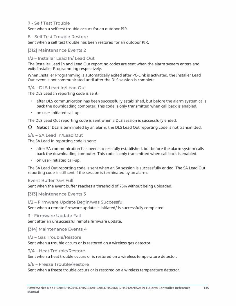
7 - Self Test TroubleSent when a self test trouble occurs for an outdoor PIR.
8 - Self Test Trouble RestoreSent when a self test trouble has been restored for an outdoor PIR.
[312] Maintenance Events 2
1/2 – Installer Lead In/ Lead OutThe Installer Lead In and Lead Out reporting codes are sent when the alarm system enters andexits Installer Programming respectively.When Installer Programming is automatically exited after PC-Link is activated, the Installer LeadOut event is not communicated until after the DLS session is complete.
3/4 – DLS Lead In/Lead OutThe DLS Lead In reporting code is sent:
• after DLS communication has been successfully established, but before the alarm system callsback the downloading computer. This code is only transmitted when call back is enabled.
• on user-initiated call-up.
The DLS Lead Out reporting code is sent when a DLS session is successfully ended.
Note: If DLS is terminated by an alarm, the DLS Lead Out reporting code is not transmitted.
5/6 – SA Lead In/Lead OutThe SA Lead In reporting code is sent:
• after SA communication has been successfully established, but before the alarm system callsback the downloading computer. This code is only transmitted when call back is enabled.
• on user-initiated call-up.
The SA Lead Out reporting code is sent when an SA session is successfully ended. The SA Lead Outreporting code is still sent if the session is terminated by an alarm.
Event Buffer 75% FullSent when the event buffer reaches a threshold of 75% without being uploaded.
[313] Maintenance Events 3
1/2 – Firmware Update Begin/was SuccessfulSent when a remote firmware update is initiated/ is successfully completed.
3 - Firmware Update FailSent after an unsuccessful remote firmware update.
[314] Maintenance Events 4
1/2 – Gas Trouble/RestoreSent when a trouble occurs or is restored on a wireless gas detector.
3/4 – Heat Trouble/RestoreSent when a heat trouble occurs or is restored on a wireless temperature detector.
5/6 – Freeze Trouble/RestoreSent when a freeze trouble occurs or is restored on a wireless temperature detector.
135PowerSeries Neo HS2016/HS2016-4/HS3032/HS2064/HS2064 E/HS2128/HS2129 E Alarm Controller ReferenceManual

7/8 – Probe Disconnected Trouble/RestoreSent when a probe disconnected trouble occurs or is restored on a wireless temperature detector.
[321] Receiver Events
2/4/6/8 – Receiver 1 - 4 FTC RestoreSent when the panel detects an FTC trouble.
[331] Module Events 1
1/2 – Module AC Trouble/RestoreThis reporting code is transmitted when a module’s AC supply fails or has been restored. Aprogrammable delay applies to both the trouble and the restore. This reporting code is sent to theSystem Maintenance call direction group.
3/4 – Module Battery Trouble/RestoreThese reporting codes are transmitted when a module’s battery voltage falls below 11.5VDC or isrestored. These reporting codes are sent to the System Maintenance call direction group.
5/6 – Module Battery Absent/RestoreThese reporting codes are transmitted when a module’s battery is detected as absent or restored.These reporting codes are sent to the System Maintenance call direction group.
[332] Module Events 2
1/2 – Module Low Voltage Trouble/RestoreSent when module voltage drops below acceptable levels or is restored.
3/4 – Module Supervisory Trouble/RestoreSent when communication with a module is lost or restored.
5/6 – Module Aux Trouble/RestoreSent when a high current output module or power supply module experiences an auxiliary voltagesupply trouble.
[335] Module Events 5
1/2 – Output 1 Fault/RestoreThis reporting code is sent when the first output on the high-current output expander module goesinto fault (open or short) or is restored.Only the first output on the high-current expander module is supervised.
[351] Alternate Communicator 1
1/2 – Alt. Comm Communications Fault/RestoreSent when the system loses or restores communications with the alternate communicator.
3/4 – Not used
5/6 – Not used
7/8 – Alt. Comm Radio/SIM Failure/RestoreSent when the alternate communicator experiences trouble or restore of the radio/SIM.
PowerSeries Neo HS2016/HS2016-4/HS3032/HS2064/HS2064 E/HS2128/HS2129 E Alarm Controller ReferenceManual
136

[352] Alternate Communicator 2
1/2 – Alternate Communicator Network Fault/RestoreSent when the alternate communicator loses or restores communication with the network.
5/6 – Alternate Communicator Ethernet Trouble /RestoreSent when the alternate communicator detects a network absent condition or DHCP failure orrestore.
[354] Alternate Communicator 4
Receiver 1 to 4 Trouble and RestoreSent when the alternate communicator detects a trouble or restore condition on receiver 1-4.1/2 – Receiver 1 Trouble/Restore3/4 – Receiver 2 Trouble/Restore5/6 – Receiver 3 Trouble/Restore7/8 – Receiver 4 Trouble/Restore
[355] Alternate Communicator 5
Receiver 1 to 4 Supervision Failure and RestoreSent when the alternate communicator detects a supervision trouble for the Ethernet receiver (1, 2)or the GPRS receiver (3, 4).1/2 – Receiver 1 Supervision Failure/Restore3/4 – Receiver 2 Supervision Failure/Restore5/6 – Receiver 3 Supervision Failure/Restore7/8 – Receiver 4 Supervision Failure/Restore
[361] Wireless Device Events
1/2 – Wireless Device AC Failure/RestoreThese options are used to enable wireless device AC failure/restore reporting codes. Thesereporting codes are sent when a wireless device experiences an AC failure/restore.
3/4 – Wireless Device Low Battery Trouble/RestoreThese options are used to enable wireless device low battery trouble/restore reporting codes.These codes are sent when a wireless device experiences a low battery trouble/restore.
5/6 – Wireless Device Fault/RestoreThese options are used to enable wireless device fault/restore reporting codes. This reporting codeis sent when a wireless device experiences a supervisory fault.
[401] System Test Events
1/2 – Walk Test Start/EndSent when installer walk test is initiated and terminated.These reporting codes are in addition to the alarm reporting codes for the zones that are trippedduring the walk test period, if configured in section [382] Communicator Option 3.
3 - Periodic Test TransmissionSent when the test transmission programmed in section [401] System Test Events occurs.
137PowerSeries Neo HS2016/HS2016-4/HS3032/HS2064/HS2064 E/HS2128/HS2129 E Alarm Controller ReferenceManual
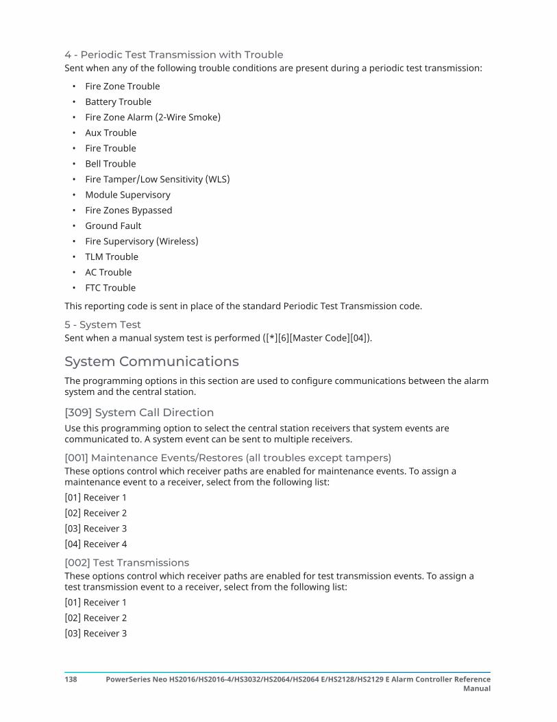
4 - Periodic Test Transmission with TroubleSent when any of the following trouble conditions are present during a periodic test transmission:
• Fire Zone Trouble• Battery Trouble• Fire Zone Alarm (2-Wire Smoke)• Aux Trouble• Fire Trouble• Bell Trouble• Fire Tamper/Low Sensitivity (WLS)• Module Supervisory• Fire Zones Bypassed• Ground Fault• Fire Supervisory (Wireless)• TLM Trouble• AC Trouble• FTC Trouble
This reporting code is sent in place of the standard Periodic Test Transmission code.
5 - System TestSent when a manual system test is performed ([*][6][Master Code][04]).
System CommunicationsThe programming options in this section are used to configure communications between the alarmsystem and the central station.
[309] System Call DirectionUse this programming option to select the central station receivers that system events arecommunicated to. A system event can be sent to multiple receivers.
[001] Maintenance Events/Restores (all troubles except tampers)These options control which receiver paths are enabled for maintenance events. To assign amaintenance event to a receiver, select from the following list:[01] Receiver 1[02] Receiver 2[03] Receiver 3[04] Receiver 4
[002] Test TransmissionsThese options control which receiver paths are enabled for test transmission events. To assign atest transmission event to a receiver, select from the following list:[01] Receiver 1[02] Receiver 2[03] Receiver 3
PowerSeries Neo HS2016/HS2016-4/HS3032/HS2064/HS2064 E/HS2128/HS2129 E Alarm Controller ReferenceManual
138

[04] Receiver 4
[310] Account CodesThese programming sections are used to set the system and partition account codes.
[000] System Account CodeThe system account code is used to identify the alarm system when communicating system eventsto the central station. The system account code can be either 4 or 6 digits long. Program a 6-digitcode only when using the SIA reporting format. SIA uses this account code for all partitions andsystem events. All other reporting formats use a 4-digit system account code to report systemmaintenance (e.g., low battery, zone fault) and test transmission events. To program a 4-digit code,add FF to the last two digits.
[001]-[008] Partition Account CodesUse these sections to program account codes for each partition.When using formats other than SIA, these account codes identify the alarm system to the centralstation when communicating partition-specific events.
Note: The system will not communicate if the account code is not programmed. When thiscondition occurs, Account Code Not Programmed is briefly displayed on the keypad whenexiting Installer Programming mode.
Note: If no phone numbers are programmed, the error message does not occur.
[311]-[318] Partition Call DirectionsUse this programming option to select the central station receivers that partition events arecommunicated to. Call directions can be programmed for each partition. Each event can be sent toone of four receivers.
[001] Alarm/ RestoreThese options control which receiver paths are enabled for Partition 1-8 Alarm and Restore eventreporting codes.To assign an event to a receiver, select one of the following options:[01] Receiver 1[02] Receiver 2[03] Receiver 3[04] Receiver 4
[002] Tampers (Including System Tampers)/ RestoreThese options control which receiver paths are enabled for Partition 1-8 Tamper and Restore eventreporting codes.To assign an event to a receiver, select one of the following options:[01] Receiver 1[02] Receiver 2[03] Receiver 3[04] Receiver 4
[003] Openings/ ClosingThese options control which receiver paths are enabled for Partition 1-8 Opening and Closing eventreporting codes. To assign an event to a receiver, select one of the following options:[01] Receiver 1
139PowerSeries Neo HS2016/HS2016-4/HS3032/HS2064/HS2064 E/HS2128/HS2129 E Alarm Controller ReferenceManual

[02] Receiver 2[03] Receiver 3[04] Receiver 4
[350] Communicator FormatsUse this programming option to assign a communicator format to each of the four receiversprogrammed in section [301]. The available communicator formats are as follows:
03 DTMF Contact ID04 SIA FSK
To assign a communications format, select a receiver (option [001]-[004]) then enter the 2-digitcode corresponding to the chosen format. For detailed descriptions of each format, ReportingCodes.
[377] Communication Variables
[001] – Swinger Shutdown
Alarms/RestoresThis value defines the number of communication attempts made for alarm/restore events, perzone, before the zone goes into swinger shutdown. Valid entries are 000 to 014. For CP-01, entriesare from 001-006.Once the programmed number of alarm/restore events have been communicated, no furtheralarm/restore events for the zone are communicated until swinger shutdown is reset. The lastrestore event is not communicated until swinger is cleared. For example, if the swinger shutdownlimit for zone alarms is set to [003], the cycle is as follows: alarm/restore, alarm/restore, alarm...8hours or arm/disarm...restore.The bell output is not activated for alarms on zones that have exceeded the swinger shutdowncounter limit. Swinger shutdown on global zones log once to the system area.
Note: Swinger shutdown resets on all partitions when any partition on the system is armed ordisarmed, or every day at midnight. For CP-01, swinger shutdown is restored after 8 hours ofinactivity.
Once reset, the alarm system communicates normally.
Note: The event buffer can follow swinger shutdown if enabled.
Tampers/RestoresThis value defines the number of times the same system tamper event occurs before going intoswinger shutdown. Valid entries are 000 to 014.
Maintenance Troubles/RestoresThis value defines the number of times the same system Maintenance (trouble) type event occursbefore going into swinger shutdown. Fire troubles follow the Maintenance Swinger Shutdownvariable.
[002] – Communication Delays
Transmission Delay (seconds)This value defines the delay before an alarm is transmitted.The delay is for zones which have the Transmission Delay attribute enabled. Valid entries are from000 to 255 seconds (0-45 seconds for CP-01). Each partition shares the same active timer. If the
PowerSeries Neo HS2016/HS2016-4/HS3032/HS2064/HS2064 E/HS2128/HS2129 E Alarm Controller ReferenceManual
140

delay is already active due to an alarm on a different partition, any new activity on another partitiondoes not restart the communications delay timer.Burglary verified events are postponed until after the transmission delay expires. When a validdisarming procedure is used while the transmission delay is active, a communications canceledmessage is briefly displayed on the keypad when the delay is canceled.
Note: For UL/ULC listed installations, the entry delay plus communication delay cannotexceed 45 seconds.
AC Failure Communication Delay (minutes or hours)This value determines the delay before an AC failure or AC restore is reported. The AC failure orrestore is still displayed immediately. Valid entries are from 000 to 255 minutes/hours (max. 180minutes for UL commercial installations). Selection of minutes or hours for the delay is set insection [382] Communicator Option 3.
Note: If AC Failure Communications Delay is programmed as 000, the AC Failure Troublereporting code is sent immediately.
Note: For ULC commercial fire monitoring, the setting shall be 180 minutes.
TLM Trouble DelayUse this section to program the number of valid checks (3 second intervals) required beforea telephone line trouble is generated. Valid entries are 000-255 for trouble annunciation andtransmission delays of 3 to 765 Seconds (12.75 Minutes).
Wireless Zone Low Battery Transmission Delay (in days)When a zone reports a low battery condition, the trouble is indicated immediately on the keypad,but the transmission to the monitoring station is delayed by the number of days programmed inthis section. If the low battery condition is not corrected before the delay expires, the low batterycondition is transmitted. The Low Battery Restore transmission is not delayed.
Delinquency Transmission DelayThe value in this section determines the period of time before a delinquency event is generated.Delinquency delay is measured in days if using closing delinquency or hours if using activitydelinquency as programmed in section [311] option 6. Valid entries are [001]-[255] or [000] todisable.
Communications Cancel WindowAfter the transmission Delay expires and a zone alarm is transmitted, the communications cancelwindow begins.If an access code is entered during this window, a reporting code is communicated and logged.If the window expires without an access code entry or a code is entered after the window, thecommunications canceled event is not logged or communicated.
Note: The cancel window does not start after an [F][M][P] key alarm.
[003] – Periodic Test Transmission CycleThis value determines the period between test transmissions. Valid entries are [000]-[255]. Whetherthis interval is in hours or days is determined by section [022], option 4.
Note: For UL residential fire installations, the test interval is 7 days.
Note: For ULC listed installations, the test interval is 24 hours.
[004] – Periodic Test Transmission Time of DayEnter a 4-digit time using the 24-hour clock format (HH:MM).
141PowerSeries Neo HS2016/HS2016-4/HS3032/HS2064/HS2064 E/HS2128/HS2129 E Alarm Controller ReferenceManual

Valid entries are from 00 to 23 for the hours (HH) and 00 to 59 for the minutes (MM).To disable the test transmission time of day, enter [9999] in this section.
Note: This time should not be set for the same time as Daylight Savings time.
Note: For UL listed installations, the default time is programmed for 04:45am. The panel willgenerate a random test transmission time within a +/- 60 minute window. Any other valueprogrammed by the installer will not be affected.
[011] – Maximum Dialing AttemptsThis section is used to program the number of dialing attempts made to each telephone numberwhen communicating. Valid entries are 002-005.
Note: For UL/ULC listed installations, this value must be set to 005.
[012] – Delay Between PSTN AttemptsThis programmable timer adds a delay before the next call is attempted over PSTN. Valid entriesare 000-255, with a default of 3 seconds (making a total of 8 seconds: 3-second delay + standard 5-second dial tone search).
[013] – Delay Between Force AttemptsThis programming option is used to set the length of time the alarm system waits between the firstdialing attempt and the force dial attempt.Valid Entries are 001-255 seconds. Default is 020.
[014] – Post Dial Wait for HandshakeThis option is used to program the length of time the communicator waits for a valid initialhandshake from the receiver after dialing the programmed telephone number. Valid entries are001 to 255 seconds.
Note: Maximum 45 seconds for UL installations.
[015] – T-Link Wait for AckThis option is used to program the length of time the communicator waits for an acknowledge aftertransmitting via IP/GS. Valid entries are 001 to 255. Default is 60 seconds.
[016] –IP/Cellular Fault Check TimerThis section is used to program the number of poll commands sent without valid poll responsesbefore the alarm system generates a trouble condition. The checks occur at 3-second intervals.Valid entries are 003-255 for trouble annunciation and transmission.The trouble restore is not delayed.
[380] Communicator Option 1
1 - Communications Enabled/DisabledON: (Default) The system communicator is enabled and all events with reporting codes arereported to the monitoring station. Refer to the Telephone Number, Reporting Code and CallDirection programming sections.OFF: The system communicator is disabled and no events are reported to the monitoring station.
Note: Disabling the communicator clears all FTC troubles.
PowerSeries Neo HS2016/HS2016-4/HS3032/HS2064/HS2064 E/HS2128/HS2129 E Alarm Controller ReferenceManual
142

2 - Restore On Bell TimeoutON: Zone restore reporting codes are not transmitted until the zone has been restored and the belltimeout has expired. If the zone is not restored when the bell cut-off time expires, the restore istransmitted when the zone physically restores or when the system is disarmed.
Note: 24-hour zones will not restore until the zone is physically restored
OFF: Zone restore reporting codes are transmitted when the zone is physically restored. If zonesare still active when the system is disarmed, the restore codes are transmitted when the system isdisarmed.
3 - Pulse DialingON: The alarm system dials telephone numbers using pulse (rotary) dialing.OFF: The alarm system dials telephone numbers using DTMF (dual tone multi-frequency) touch-tone dialing.
4 - Pulse Dial after 5th AttemptON: If DTMF dialing is enabled, the alarm system dials telephone numbers using DTMF dialing forthe first 4 attempts. If unsuccessful, the alarm system switches to pulse (rotary) dialing for theremaining attempts.OFF: If DTMF dialing is enabled, the alarm system dials telephone numbers using DTMF dialing forall dialing attempts.
5 - Parallel CommunicationsON: Parallel communications is enabled. The alarm system attempts to communicate through allavailable receivers at the same time. Once acknowledgment is provided by any of the receivers, thealarm system communicates the next event. If more than one receiver is configured for PSTN, thebackup procedure described below is followed.OFF: Parallel communications is disabled. If receiver 1 fails, the alarm system attempts tocommunicate with the next available receiver (2-4) in sequence.
Note: See [384] Communicator Backup Options for communicator backup programming.
6 - Alternate DialON: After each failed dialing attempt, the communicator switches to the next backup receiver in thesequence:
• Receiver 2 backs up Receiver 1• Receiver 3 backs up Receiver 2• Receiver 4 backs up Receiver 3
This continues until communication is successful or the sequence has been repeated 5 times(depending on the number of maximum dialing attempts). If all 5 attempts fail, an FTC troublefor the primary phone number is logged. All backup receivers automatically use the same calldirections and format as the primary receiver.OFF: After 5 failed attempts to communicate with the primary receiver, the communicator switchesto the next backup receiver in the sequence and makes up to 5 more attempts. This continues untilcommunication is successful or until all backup receivers fail, at which point an FTC trouble for theprimary number is logged.
7 - Reduced Dialing AttemptsON: If a TLM trouble is present, The alarm system immediately attempts to call the backup receiver.This option only applies to PSTN. Backup communications must be enabled. See option 5, ParallelCommunications.
143PowerSeries Neo HS2016/HS2016-4/HS3032/HS2064/HS2064 E/HS2128/HS2129 E Alarm Controller ReferenceManual

A minimum of two receivers should be enabled for this feature to operate as intended. This featureshould not be enabled unless the panel is programmed to use backup communication paths.OFF: If a TLM trouble is present, the number of dialing attempts programmed shall be attemptedbefore moving on to the backup receiver.
8 - Activity DelinquencyON: Inactivity on a partition for a programmed duration (section [377] option 002, DelinquencyTransmission Delay) transmits a Delinquency code to the central station. This option is designed tohelp monitor the elderly or disabled. The counter is reset if zone activity is detected or if the systemis armed. The Delinquency Transmission Delay is in hours.
Note: Delinquency code is not transmitted while Away armed. Activity on bypassed zones doesnot affect this timer.
OFF: The Delinquency reporting code is sent when the programmed number of days fordelinquency (section [377]) expires without the partition being Armed. Once the code is sent, thetimer is not started again until the partition has been armed. Each day programmed in the counterrepresents one day plus the time it takes for the partition to reach midnight. To disable this feature,program 000 in section [377]>[002] option 5.
[381] Communicator Option 2
1 - Keypad RingbackON: When the Opening After Alarm reporting code is successfully transmitted to a programmedtelephone number, the keypad emits a series of 8 beeps to confirm to the occupant that the codewas sent and received. Ringback occurs for each successfully reported Opening After Alarm code.OFF: When the Opening After Alarm reporting code is successfully transmitted to a programmedtelephone number, the keypad does not sound ringback.
2 - Bell RingbackON: When the Opening After Alarm reporting code is successfully transmitted to a programmedtelephone number, the siren emits a series of 8 squawks to confirm to the occupant that the codewas sent and received. Ringback occurs for each successfully reported Opening After Alarm code.OFF: When the Opening After Alarm reporting code is successfully transmitted to a programmedtelephone number, the siren does not sound ringback.
4 - Closing Confirmation Enabled/DisabledON: When a Closing reporting code is successfully transmitted to a programmed telephonenumber, the keypad emits a series of 8 beeps to confirm to the occupant that the Closing Code wassent and received.OFF: No keypad ringback is generated when a Closing reporting code is successfully transmitted.
8 - Communications Priority Enabled/DisabledAbout this task:ON: Events follow the priority level indicated in ULC-S559 standard.Concurrent event communications are prioritized in the following order (highest to lowest priority):
1. Fire Alarms2. CO Alarm3. Fire Supervisories4. Fire Trouble5. Monitoring (Medical, Panic or Security)6. All others such as restorals for fire alarms, supervisories, troubles and monitoring.
PowerSeries Neo HS2016/HS2016-4/HS3032/HS2064/HS2064 E/HS2128/HS2129 E Alarm Controller ReferenceManual
144

7. FTC'ed events
ResultOFF: Events are communicated in the order they occur.
Note: Must be ON for ULC commercial fire monitoring listed installations.
[382] Communicator Option 3
1 - Not Used
2 - Walk Test CommunicationsON: Zone alarms that occur during Walk Test are communicated if programmed to do so.OFF: Zone alarms during Walk Test are not communicated. FMP key alarms are still communicated.
4 - Call Waiting CancelON: The call waiting cancel string ([304] Call Waiting Cancel String) is used on the first attempt todial each phone number. It is not used on any further dialing attempts.OFF: The call waiting cancel string is not dialed.
55 - Alternate Communicator Enable/DisableON: The system communicates using the alternate communicator. All related programmingoptions, reporting and supervision are enabled when programmed via PC-Link2.OFF: The alternate communicator and all associated programming functionality are disabled. Theauto time update feature is disabled.
Note: If alternate communicator troubles are present when the communicator is disabled, thetroubles are logged, communicated, and cleared from [*][2]. When the communicator is re-enabled, the trouble conditions are again logged, communicated and indicated in [*][2]. Thisoption must be enabled when attempting to perform a firmware upgrade using the PC-linkheader.
6 - AC Failure Communication Delay in Hours/MinutesON: The AC failure communication delay (section [377]>[002] option 2) is programmed in hours.OFF: The AC failure communication delay is programmed in minutes.
8 - Tamper LimitON: When disarmed, the system only communicates module tampers. Zone tampers are notcommunicated.OFF: When disarmed, the system communicates all tampers.
[383] Communicator Option 4
1 - Phone Number Account CodeON: The account code communicated to the central station follows the phone number the event isprogrammed to communicate on (programmed in section [310] Account Codes):
• Receiver 1 all events will follow partition 1 account code• Receiver 2 all events will follow partition 2 account code• Receiver 3 all events will follow partition 3 account code• Receiver 4 all events will follow partition 4 account code
OFF: Events follow the account code assigned to each partition when communicating.
145PowerSeries Neo HS2016/HS2016-4/HS3032/HS2064/HS2064 E/HS2128/HS2129 E Alarm Controller ReferenceManual

Note: This feature only works with CID
2 - 4 or 6-Digit System Account CodeON: The programmable account code in section [310][000] is 6 digits long (used for SIA format).OFF: The programmable account code in section [310][000] is 4 digits long.
5 - Communicate FTC EventsON: The alarm system communicates FTC (failure to communicate) events. The FTC Trouble/Restorereporting code transmission follows the call direction the events are assigned to.OFF: FTC events are not communicated. FTC Trouble/Restore reporting codes are communicated tothe Maintenance call direction group after the next successful communication.
6 - Not used
[384] Communicator Backup Options
2 - Receiver 2 Backup OptionON: Receiver 2 backs up Receiver 1. Receiver 2 is only used if an FTC event is detected on Receiver 1.Receiver 2 uses the same format programmed for Receiver 1.OFF: Receiver 2 is independent and will communicate if a number and format are programmed.
3 - Receiver 3 Backup OptionON: Receiver 3 backs up Receiver 2. Receiver 3 is only used if an FTC event is detected on Receiver 2.Receiver 3 uses the same format programmed for Receiver 2.OFF: Receiver 3 is independent and will communicate if a number and format are programmed.
Receiver 4 Backup OptionON: Receiver 4 backs up Receiver 3. Receiver 4 is only used if an FTC event is detected on Receiver 3.Receiver 4 uses the same format programmed for Receiver 3.OFF: Receiver 4 is independent and will communicate if a number and format are programmed.
[385] Audio Module Talk\Listen Mask
1- Talk/Listen on Receiver 1ON: 2-way audio sessions can be initiated over receiver 1.OFF: Regardless of other 2-way audio programming, 2-way audio sessions cannot be initiated overreceiver 1.
2- Talk/Listen on Receiver 2ON: 2-way audio sessions can be initiated over receiver 2.OFF: Regardless of other 2-way audio programming, 2-way audio sessions cannot be initiated overreceiver 2.
3-Talk/Listen on Receiver 3ON: 2-way audio sessions can be initiated over receiver 3.OFF: Regardless of other 2-way audio programming, 2-way audio sessions cannot be initiated overreceiver 3.
4-Talk/Listen on Receiver 4ON: 2-way audio sessions can be initiated over receiver 4.
PowerSeries Neo HS2016/HS2016-4/HS3032/HS2064/HS2064 E/HS2128/HS2129 E Alarm Controller ReferenceManual
146

OFF: Regardless of other 2-way audio programming, 2-way audio sessions cannot be initiated overreceiver 4.
DLS ProgrammingDownloading allows programming of the entire alarm system via a computer. All functions andfeatures, changes and status, such as trouble conditions and open zones, can be viewed orprogrammed by downloading.The following downloading options are available:
• 6-hour window on start up: When the alarm system is powered up, downloading access isavailable for 6 hours. This provides the option of downloading without having to complete anykeypad programming.
• Double call method: The installer initiates a downloading window by calling the alarm system,hanging up, then calling back again.
• User enabled DLS window: The user initiates a downloading window using [*][6][Master code][05]. This can be a 6-hour window where the installer initiates and terminates downloading asmany times as necessary, or it can be a 1-hour, 1 use window.
• User initiated call-up: the user can initiate a downloading session using [*][6][Master Code][06].
• On-site downloading using PC-Link: The installer connects a computer directly to the alarmsystem to perform on-site downloading.
• Auto event buffer upload: The Event buffer is automatically uploaded to the DLS/SA computerwhen it reaches 75% full.
Refer to the DLS/SA programming sections described below for configuration options.
[401] DLS/SA Options
1 - Double CallON: Calls for downloading or SA are answered if a successful double call routine is detected. Havethe downloading computer call the system and let the telephone line ring once or twice. After 1 or2 rings, hang up. If called back within the duration of the double call timer (section [405]), the alarmsystem answers on the first ring.OFF : Incoming calls are not answered using the double call routine unless the user enables the DLSwindow.
Note: This feature controls the DLS window for PSTN connections only.
2 - User Enables/Disables DLSON : The [*][6][Master Code][05] command enables a 6-hour window where, on power-up,downloading calls are answered if a successful double call routine is detected.OFF: The user cannot enable a downloading window.
3 - DLS CallBackON : When a downloading call is answered, both the computer and the alarm system hang up. Thealarm system then calls the downloading computer back using the downloading telephone numberand begins the DLS session.
Note: Disable this option if using more than one downloading computer.
OFF : After successful validation, the downloading computer gains immediate access to the alarmsystem.
147PowerSeries Neo HS2016/HS2016-4/HS3032/HS2064/HS2064 E/HS2128/HS2129 E Alarm Controller ReferenceManual
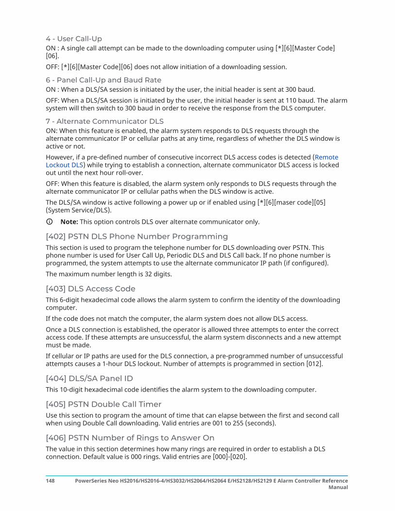
4 - User Call-UpON : A single call attempt can be made to the downloading computer using [*][6][Master Code][06].OFF: [*][6][Master Code][06] does not allow initiation of a downloading session.
6 - Panel Call-Up and Baud RateON : When a DLS/SA session is initiated by the user, the initial header is sent at 300 baud.OFF: When a DLS/SA session is initiated by the user, the initial header is sent at 110 baud. The alarmsystem will then switch to 300 baud in order to receive the response from the DLS computer.
7 - Alternate Communicator DLSON: When this feature is enabled, the alarm system responds to DLS requests through thealternate communicator IP or cellular paths at any time, regardless of whether the DLS window isactive or not.However, if a pre-defined number of consecutive incorrect DLS access codes is detected (RemoteLockout DLS) while trying to establish a connection, alternate communicator DLS access is lockedout until the next hour roll-over.OFF: When this feature is disabled, the alarm system only responds to DLS requests through thealternate communicator IP or cellular paths when the DLS window is active.The DLS/SA window is active following a power up or if enabled using [*][6][maser code][05](System Service/DLS).
Note: This option controls DLS over alternate communicator only.
[402] PSTN DLS Phone Number ProgrammingThis section is used to program the telephone number for DLS downloading over PSTN. Thisphone number is used for User Call Up, Periodic DLS and DLS Call back. If no phone number isprogrammed, the system attempts to use the alternate communicator IP path (if configured).The maximum number length is 32 digits.
[403] DLS Access CodeThis 6-digit hexadecimal code allows the alarm system to confirm the identity of the downloadingcomputer.If the code does not match the computer, the alarm system does not allow DLS access.Once a DLS connection is established, the operator is allowed three attempts to enter the correctaccess code. If these attempts are unsuccessful, the alarm system disconnects and a new attemptmust be made.If cellular or IP paths are used for the DLS connection, a pre-programmed number of unsuccessfulattempts causes a 1-hour DLS lockout. Number of attempts is programmed in section [012].
[404] DLS/SA Panel IDThis 10-digit hexadecimal code identifies the alarm system to the downloading computer.
[405] PSTN Double Call TimerUse this section to program the amount of time that can elapse between the first and second callwhen using Double Call downloading. Valid entries are 001 to 255 (seconds).
[406] PSTN Number of Rings to Answer OnThe value in this section determines how many rings are required in order to establish a DLSconnection. Default value is 000 rings. Valid entries are [000]-[020].
PowerSeries Neo HS2016/HS2016-4/HS3032/HS2064/HS2064 E/HS2128/HS2129 E Alarm Controller ReferenceManual
148

Note: If Double-Call option and Number of Rings to Answer are enabled, either one will workdepending on how the installer calls the alarm system.
[407] SA Access CodeThis 6-digit hexadecimal code allows the alarm system to confirm the identity of the downloadingcomputer.If the code does not match the computer, the alarm system does not allow uploading/downloading.Programming the access code as FFFFFF disables SA access.Once an SA connection is established, multiple attempts to input the correct downloading accesscode (programmed in [012]) is allowed.The operator is allowed three attempts to enter the correct access code. If these attempts areunsuccessful, the alarm system disconnects and a new attempt must be made.If cellular or IP paths are used for the SA connection, up to five unsuccessful attempts causes a 1-hour SA lockout (Remote Lockout DLS).
[410] Automatic DLS/SA Options
[001] – Auto DLS Options
Periodic DLSON: Upload/download commands programmed in advance (batch files) are periodicallydownloaded to the DLS computer.See below to program the times and days when this occurs.
Note: The computer must be waiting for a call in order for this feature to work.
OFF: The alarm system does not periodically call the downloading computer.
DLS on Event Buffer %75 FullON: The alarm system automatically calls the downloading computer with DLS when the EventBuffer 75% full event occurs.This option is independent of the actual transmission of the Event Buffer 75% full event (the eventdoes not need to be transmitted for the panel to perform the automatic upload).The panel first communicates the Event Buffer 75% full event (if enabled) using either PSTN or IPand then performs the automatic download.OFF: The alarm system does not automatically call the downloading computer when the EventBuffer 75% full event occurs.
DLS on Programming ChangeON: When the panel returns to the "Ready to Arm" screen after a programming change, 15 minuteslater the alarm system automatically calls the downloading computer.OFF: The alarm system does not automatically call the downloading computer when the systemprogramming changes.
[002] Periodic DLS DaysThis section is used to program the number of days between periodic DLS downloads. Valid entriesare from 001 to 255 days.
[003] Periodic DLS TimeThis section is used to program the time of day periodic DLS download takes place. Time is in 24-hour format and the default is 00:00 (midnight).
149PowerSeries Neo HS2016/HS2016-4/HS3032/HS2064/HS2064 E/HS2128/HS2129 E Alarm Controller ReferenceManual

[007] Delay Call WindowThis section is used to define a user call-up window. Users can only initiate a downloading sessionduring this window. When a value is entered in this section, the setting in Periodic DLS Time (seethe option above) is overridden. When 00:00 is entered in this field, the alarm system initiates a DLScall at the time programmed in Periodic DLS Time. Start and end times must be defined using 24-hour format (e.g., 13:30) and cannot span a day (e.g., start time of 23:00 and an end time of 01:00).
Virtual InputsWhen using an alternate communicator, virtual zones can be mapped to configured system zones.
[560][001]-[032]Assign corresponding 3 digit zone number to virtual input and then the virtual input can becontrolled by an alternate communicator. Refer to the communicator manual for more information
Schedule ProgrammingThe sections described below are used for programming scheduled operating times for PGMcommand outputs 1-4.
[601]-[604] Programming Schedule 1-4These sections are used to define schedules for PGM command outputs 1-4 operation. When a PGMis configured for timed output operation, it activates at the programmed start time and will turn offafter the programmed duration. For example, 5 seconds.Each schedule contains 4 intervals, for Command Outputs 1-4. Within each interval, a start time andend time can be programmed for each day of the week. Holiday schedules 1-4 can also be selected.To enable the command output to follow a schedule, program the command output in section [009]and then enter schedule 001 - 004 in section [011].
[101]-[102] Set Start Time/ End TimeUsed to program the time of day the schedule interval begins and ends. (HH:MM). Valid entriesare 0000-2359 and 9999. The end time must be equal to or greater than the start time. 9999 is usedwhen an interval needs to extend past 24 hours. To do this, program the start time of the firstinterval then the end time with 9999. Program the start time of the second interval as 9999 and theend time with the desired time when the output should deactivate. Select the day of the week theschedule will end.
Note: If two intervals in a schedule are programmed with the same start time, the schedulefollows the interval with the longest end time.
[103] Days AssignmentUsed to program the day of the week that the schedule interval starts and ends. Use the scroll keysto select a day then toggle the option on. Multiple days of the week can be enabled.
[104] Holiday AssignmentProgram PGMs to follow holiday schedule group 1-4. Select (Y) to enable. If all days of the week foran interval are disabled (N), the schedule activates on the enabled holidays.
[711]-[714] Holiday SchedulesUse this section to program holiday schedules. During holiday schedules, other scheduled eventsdo not occur. Enter section 711 to 714 for holiday group 1 to 4.Each of the four available holiday groups can have up to 99 holiday schedules programmed.
PowerSeries Neo HS2016/HS2016-4/HS3032/HS2064/HS2064 E/HS2128/HS2129 E Alarm Controller ReferenceManual
150

[001]-[099] Holiday Dates 1-99Program holiday dates in the following format: MMDDYYMM valid entries are 01 to 12DD valid entries are 01 to 31YY valid entries are 00 to 99
[802] Audio Verification Module ProgrammingThis module provides 2-way audio communication between the central station and the occupantsof the premises.
Note: For complete programming descriptions and worksheets, see the Audio Verificationmodule installation manual.
Wireless Programming
[804] Wireless ProgrammingThis programming section is used to enroll, program and delete wireless devices. Note that theHSM2HOSTx wireless transceiver or RF model keypad must be installed in order to enroll wirelessdevices.
[000] – Wireless Device EnrollmentTo enroll a wireless device using this method, press and hold the Enroll button on the device for2-5 seconds until the LED illuminates then release the button. The alarm system automaticallydiscovers the device and the keypad displays a confirmation message. The device ID, type and thenext available zone number are displayed. Press [*] to accept or scroll to another available zonenumber. Batteries must be installed in the wireless device in order to enroll.
Note: Ensure wireless signal strength is adequate before mounting the wireless device. Seethe instructions provided with the wireless device for details.
Note: For complete wireless device programming descriptions and worksheets, see theHSM2Hostx wireless transceiver installation manual.
[850] Cellular Signal StrengthThis section is used to view both the cellular signal strength and the radio technology in use.Table 22: Cellular TechnologyDisplay TechnologyGP GPRSED EDGEHS HSPAH+ HSPACD CDMAEV EVDO
5 bars indicate maximum signal strength. 0 bars indicate the communicator is not connected to thenetwork.
[851] Alternate Communicator ProgrammingSee the alternate communicator installation manual for programming instructions.
151PowerSeries Neo HS2016/HS2016-4/HS3032/HS2064/HS2064 E/HS2128/HS2129 E Alarm Controller ReferenceManual

[860] Display Keypad Slot NumberThe 2-digit slot number of the keypad being used is displayed in this read only section.
[861]-[876] Keypad ProgrammingUse section [861] to [876] to configure keypads 1 to 16. For information on keypad programming,refer to the installation sheet supplied with the keypad.
Note: For EN50131 compliant installations [861][021] options 1 and 2 must be disabled.
[899] Template ProgrammingTemplate programming allows quick programming of the minimum functions required for basicoperation. This section is used to view current template programming options and to define certainsystem parameters. Press the (#) key to accept the displayed value and advance to the next option.The following options are available:
• 5-digit Template Code: Displays the current 5-digit template programming code (default:00000). Each digit in the code selects a set of pre-defined programming options, as describedbelow:
- Digit 1 - zone 1-8 definition options- Digit 2 - system EOL options- Digit 3 - alarm controller communications options- Digit 4 - reporting code configurations- Digit 5 - DLS connection options
• Central Station Telephone Number: The phone number used to contact the central monitoringstation (32 character limit).
• Central Station Account Code: The account code used in programming section [310]. This is a 4or 6-digit entry.
• Partition Account Code: Used to identify partition-specific events. All 4 digits must be enteredin order to complete the entry.
• This account code is entered into programming section [310][001].• DLS Access Code: The 6-digit DLS access code used in programming section [403].• Partition 1 Entry Delay: The 3-digit entry delay duration for partition 1, in seconds, used in
programming [005][001] option 1.• Partition 1 Exit Delay: The 3-digit exit delay duration for partition 1, in seconds, used in
programming section [005][001] option 3.• Installer Code: The 4, 6 or 8-digit installer access code used in programming section [006][001].
For more information on template programming, .
Systems Information
[900] System Information
[000] – Control Panel VersionThis read-only section contains the model number, software version, hardware revision, of thealarm controller. For example, an entry of 1234 is read as version 12.34.
PowerSeries Neo HS2016/HS2016-4/HS3032/HS2064/HS2064 E/HS2128/HS2129 E Alarm Controller ReferenceManual
152

[001]-[524] – Module InformationThis read-only section is used to view the model number, software version, and hardware revisioninformation of the modules enrolled on the alarm system.To view information for a specific module, scroll to the corresponding section:[001]-[016] keypads[101]-[115] 8-zone expansion module[201] 8-output expansion module[460] Alternate Communicator[461] HSM2Host module[501]-[504] 1A power supply module[521]-[524] high-current output modules 1-4
[901] Installer Walk Test Mode Enable/DisableThis mode tests the operation of each detector in the system. Enter section [901] to initiate a walktest. While in Walk Test mode, the Ready, Armed, and Trouble LED's on the keypad flash to indicatethat the test is active. When a zone is tripped during the test, a 2-second tone sounds on all systemkeypads to indicate that the zone is working correctly.After 10 minutes without zone activity, the alarm system emits 5 beeps every 10 seconds from allkeypads. After another 5 minutes of inactivity, Walk Test terminates automatically.To manually exit walk test mode, enter [901] again.
Module ProgrammingUse this section to add, remove and confirm the following modules:
• Keypads Compatible Devices
• 8-zone expander module (HSM2108)• 8-output expander module (HSM2208)• Power supply (HSM2300)• 4-output power supply (HSM2204)• Wireless transceiver (HSM2HOSTx)• Audio Verification Module (HSM2955)
Once added, modules are supervised by the system.
[902] Add/Remove ModulesModules can be enrolled automatically our manually. In either case, the serial number of the deviceis used as an identifier.Select one of the enrollment options described below.
153PowerSeries Neo HS2016/HS2016-4/HS3032/HS2064/HS2064 E/HS2128/HS2129 E Alarm Controller ReferenceManual

[000] – Auto Enroll ModulesWhen this mode is selected, the alarm system automatically enrolls all modules connected to theCorbus. The total number of modules currently enrolled are displayed on the keypad.
• Enter sub-section [000] to begin auto enrollment of all new modules. The auto enroll screenwill show the following:
- KP = Number of keypad type modules- IO = Number of zone and output type modules- M = Number of other type modules
Devices are assigned to the next available slot. The slot assignment can be modified usingsubsections [002] and [003].
[001] – Enroll ModulesTo enroll modules individually:
1. Enter programming section [902][001].2. When prompted, key in the serial number of the module found on the PCB. An error tone is
sounded if an invalid serial number is used.3. To cancel enrollment of a module, press [#].
[002] – Module Slot Assignment (LED, LCD, ICON)This section is used to change the slot number a module is enrolled in. To change the slot number:
1. Enter programming section [902][002].2. Key in the serial number of the module.3. When prompted, key in the new two-digit slot number. The previous slot assignment is
replaced with the new one. An error tone sounds if an invalid slot number is keyed in.
[003] – Edit Module Slot Assignment (LCD Keypad Only)Like [002], this section is also used to change the slot number of a module. With this option,however, the serial number is not required. To change the slot number:
1. Enter programming section [902][002].2. Use the scroll keys to locate the module then press [*] to select.3. Key in the new two-digit slot number. The previous slot assignment is replaced with the new
one. An error tone sounds if an invalid slot number is keyed in.
Deleting ModulesThe following sections are used to remove modules from the system:
PowerSeries Neo HS2016/HS2016-4/HS3032/HS2064/HS2064 E/HS2128/HS2129 E Alarm Controller ReferenceManual
154

[101] – Keypads
[102] – 8-zone Expander Modules
[103] – 8-output Expander Modules
[106] – HSM2Host
[108] – HSM2955
[109] – Power Supply
[110] – 4 High Current Output
1. After entering section [902], scroll to the module type you want to delete (101-110).2. Press [*] to select the module type then scroll to the specific module you want to delete.3. Press [*] to select the module then, when prompted, press [*] again to delete.
[903] Confirm ModuleAbout this task:The following sections are used to confirm enrollment of individual modules, their serial and slotnumbers, and to locate them physically:[000] – View All Modules[101] – Keypads[102] – 8-zone Expander Modules[103] – 8-output Expander Modules[106] – HSM2Host[108] – HSM2955[109] – Power Supply[110] – 4 High Current OutputTo confirm a module:
1. Enter section [903]>[000] to view all enrolled modules or scroll to the module type you wantto confirm (101-110).
2. Press [*] to select the module type then scroll to the specific module you want to confirm.Press [*] to enter Confirmation mode. The module’s serial number and slot number aredisplayed on the keypad and the status LEDs on the device flash. This continues untilconfirmation mode for the device is exited via the [#] key.
Note: Keypad Blanking (section [016], option 3) must be disabled to confirm keypads.
Note: When using an LED or ICON keypad, use the following table to match the numberdisplayed on the keypad to a module.
Table 23: Table 19 Module numbers when programming with an LED or ICON keypad# displayed on keypad Model # Description18 HSM2108 Neo 8 zone expander module19 HSM2HOST Neo PowerG wireless tranceiver
module24 HSM2204 Neo 4 high current output
module28 HSM2208 Neo 8 output expander module30 HSM2300 Neo 1A power supply module50 HS2LCD Neo 2x16 LCD keypad
155PowerSeries Neo HS2016/HS2016-4/HS3032/HS2064/HS2064 E/HS2128/HS2129 E Alarm Controller ReferenceManual

Table 23: Table 19 Module numbers when programming with an LED or ICON keypad# displayed on keypad Model # Description51 HS2ICN Neo Icon Keypad52 HS2LCDP Neo 2x16 LCD keypad with Prox53 HS2ICNP Neo Icon Keypad with Prox56 HS2LED Neo 16 LED keypad57 HS2TCHP Neo Touchscreen Keypad with
Prox59 HS2LCDRF Neo 2x16 LCD RFK keypad5A HS2ICNRF Neo Icon RFK Keypad5B HS2LCDRFP Neo 2x16 LCD RFK keypad with
Prox5C HS2ICNRFP Neo Icon RFK Keypad with Prox60 HS2LCDWF Neo 2x16 LCD wirefree keypad67 HS2TCHWF Neo Touchscreen wirefree
Keypad6B HS2LCDWFP Neo 2x16 LCD wirefree keypad
with Prox6D HS2LCDWFPV Neo 2x16 LCD wirefree keypad
with Prox and Voice95 HSM2955 Neo Audio alarm verification
module96 HSM2955R Neo Audio alarm verification
module with Recording
Testing
[904] Wireless Placement TestThis test is used to determine RF signal status for wireless devices and can be performed at asystem keypad or at the individual device. These instructions pertain to testing at the keypad. Forinstructions on placement testing at the device, refer to the installation sheet included with thewireless equipment.The following test modes are available:
[001]-[128] Placement Test Zones 1-128Test wireless devices individually by zone (LCD keypads only).
[521]-[528] Placement Test Repeaters 1-8Test each enrolled wireless repeater (LCD keypads only).
[551]-[566] Placement Test Sirens 1-16Test each enrolled wireless siren (LCD keypads only).
[601]-[632] Placement Test Wireless keys 1-32Test individual wireless keys. Once in this section, press a button on the wireless key to begin thetest (LCD keypads only).
PowerSeries Neo HS2016/HS2016-4/HS3032/HS2064/HS2064 E/HS2128/HS2129 E Alarm Controller ReferenceManual
156

[701]-[716] Placement Test Wireless Keypads 1-16Test each enrolled wireless keypad (LCD keypads only).Two test results are provided:
• 24-hour: Average status results received during a 24-hour period.• Now: Signal status results of the current test.
During testing, the Ready and Armed LED's flash to indicate data is being received. A flashingTrouble LED indicates RF interference. The following status indicators may be displayed:Table 24: Table 19 Wireless Device Status IndicationsKeypad StatusStrong Strong signal strengthGood Good signal strengthPoor Poor signal strength1-Way The device is operating in 1-way mode only. The
alarm panel cannot configure or control thedevice
Not Test Displayed as the Now result if no test wasperformed.
None Always displayed as the 24-hour result whentesting wireless keys.
[912] Soak TestThis feature is used to diagnose false alarms. After a false alarm has occurred on a zone, Soak Testmode impedes any audible alarm conditions or additional false alarm reporting. A record of thefalse alarm is stored for diagnostic purposes.
[000] – Soak Test DurationThis option is used to program the length of time the system remains in soak test. The default is 14days.
[001]-[128] Zone Soak TestSoak test can be performed on individual zones. The zone remains in soak test, regardless of thestatus of the system, until the soak test timer has expired. If the system is armed when the timerexpires, the zones are removed from soak test when the system is disarmed.No communications occur for events from a zone in soak test, with the exception of low battery andlow battery restore events and faults generated by low sensitivity in a smoke detector.A message indicating that the zone is in soak test is displayed when scrolling left or right in thebase disarmed keypad menu.
Note: Soak test is not applied to temperature detector events if it is enabled.
[982] Battery Settings
[000] – Panel Battery Settings01 – When disabled, the panel battery is charged at 400mA. When enabled, the battery is charged at700mA.
[010] – High Current Output BatteryEnables and disables the high-current battery charge option for HSM2204 1-4.
157PowerSeries Neo HS2016/HS2016-4/HS3032/HS2064/HS2064 E/HS2128/HS2129 E Alarm Controller ReferenceManual

[020] – 1A Power Supply BatteryEnables and disables the high-current battery charge option for HSM2300 1-4.
Defaults
[989] Default Master CodeThis section is used to default the master code to the factory default. After entering this section, keyin the installer code then 989. [989][installer code][989] or [*].
Note: Feature is only available for models of NEO.
[990] Installer Lockout Enable/DisableWhen this option is enabled, an installer can not perform a hardware default; attempts to do so arelogged to the event buffer.An audible indication of installer lockout is provided when powering up the alarm system (thephone line relay clicks rapidly). Software default changes can still be made while installer lockout isenabled.[990][installer code][990] or [*].
[991] Default KeypadsThis programming option is used to return system keypads to factory default settings.
[901]- [916] – Default Keypads 1-16This section resets individual keypads to factory defaults. After entering this section, select thekeypad to default, key in the installer code then 991 (or press [*]).
[999] – Default All KeypadsThis section resets all system keypads to factory defaults. After entering this section, key in theinstaller code then (*) or 991.
[993] Default Alternate CommunicatorThis section resets the alternate communicator to factory defaults. Enter [993][installer code][993or *].
[996] Default Wireless ReceiverThis section resets the wireless receiver (HSM2HOSTx) to factory defaults. Enter [996][installercode][996 or *].
[998] Default HSM2955This section resets the audio module (HSM2955) to factory defaults. Enter [998][installer code][998or *].
[999] Default SystemThis section resets the alarm controller to factory defaults. Enter [999][installer code][999 or *].
PowerSeries Neo HS2016/HS2016-4/HS3032/HS2064/HS2064 E/HS2128/HS2129 E Alarm Controller ReferenceManual
158

Programming
Programming WorksheetsNote: EN listed options are required for EN 50131 Compliant Installations.
Label Programming[000] Label ProgrammingDescription on [000] Language Selection
[000] – Language Selection (2-digit decimal; Default: 01)01 – English02 – Spanish03 – Portuguese04 – French05 – Italian
06 – Dutch07 – Polish08 – Czech09 – Finish10 – German
11 – Swedish12 – Norwegian13 – Danish14 – Hebrew15 – Greek
16 – Turkish18 – Croatian19 – Hungarian20 – Romanian21 – Russian
22 – Bulgarian23 – Latvian24 – Lithuanian25 – Ukrainian26 – Slovakian
27 – Serbian28 – Estonian29 – Slovenian
[000] [001] Zone Labels (2 x 14 Characters)Description on [001]-[128] Zone Labels
001: 002: 003:
004: 005: 006:
007: 008: 009:
010: 011: 012:
013: 014: 015:
016: 017: 018:
019: 020: 021:
022: 023: 024:
025: 026: 027:
028: 029: 030:
031 032: 033:
034: 035: 036:
037: 038: 039:
040: 041: 042:
043: 044: 045:
046: 047: 048:
049: 050: 051:
052: 053: 054:
055: 056: 057:
058: 059: 060:
061: 062: 063:
064: 065: 066:
067: 068: 069:
070: 071: 072:
073: 074: 075:
076: 077: 078:
079: 080: 081:
159PowerSeries Neo HS2016/HS2016-4/HS3032/HS2064/HS2064 E/HS2128/HS2129 E Alarm Controller ReferenceManual

082: 083: 084:
085: 086: 087:
088: 089: 090:
091: 092: 093:
094: 095: 096:
097: 098: 099:
100: 101: 102:
103: 104: 105:
106: 107: 108:
109: 110: 111:
112: 113: 114:
115: 116: 117:
118: 119: 120:
121: 122: 123:
124: 125: 126:
127: 128:
[000] 051 – Zone Tamper Label (1 x 14 Characters):052 – Zone Fault Label (1 x 14 Characters):
064 – CO Alarm Message (2 x 14 Characters):
065 – Fire Alarm Message (2 x 14 Characters):
066 – Fail to Arm Event Message (2 x 16 Characters):
067 – Alarm When Armed Event Message (2 x 16 Characters):
100 – System Label (1 x 14 Characters):
101 – Partition 1 Label (1 x 14 Characters):
102 – Partition 2 Label (1 x 14 Characters):
103 – Partition 3 Label (1 x 14 Characters):
104 – Partition 4 Label (1 x 14 Characters):
105 – Partition 5 Label (1 x 14 Characters):
106 – Partition 6 Label (1 x 14 Characters):
107 – Partition 7 Label (1 x 14 Characters):
108 – Partition 8 Label (1 x 14 Characters):
201 – Partition 1 Command OutputLabels
001 – Partition 1 Command Output 1:
(2 X 14 ASCII) 002 – Partition 1 Command Output 2:
Descriptions on [201]-[208][001]-[004]Partition Command Output Labels
003 – Partition 1 Command Output 3:
004 – Partition 1 Command Output 4:
202 – Partition 2 Command OutputLabels
001 – Partition 2 Command Output 1:
(2 X 14 ASCII) 002 – Partition 2 Command Output 2:
003 – Partition 2 Command Output 3:
004 – Partition 2 Command Output 4:
203 – Partition 3 Command OutputLabels
001 – Partition 3 Command Output 1:
(2 X 14 ASCII) 002 – Partition 3 Command Output 2:
PowerSeries Neo HS2016/HS2016-4/HS3032/HS2064/HS2064 E/HS2128/HS2129 E Alarm Controller ReferenceManual
160

003 – Partition 3 Command Output 3:
004 – Partition 3 Command Output 4:
204 – Partition 4 Command OutputLabels
001 – Partition 4 Command Output 1:
(2 X 14 ASCII) 002 – Partition 4 Command Output 2:
003 – Partition 4 Command Output 3:
004 – Partition 4 Command Output 4:
205 – Partition 5 Command OutputLabels
001 – Partition 5 Command Output 1:
(2 X 14 ASCII) 002 – Partition 5 Command Output 2:
003 – Partition 5 Command Output 3:
004 – Partition 5 Command Output 4:
206 – Partition 6 Command OutputLabels
001 – Partition 6 Command Output 1:
(2 X 14 ASCII) 002 – Partition 6 Command Output 2:
003 – Partition 6 Command Output 3:
004 – Partition 6 Command Output 4:
207 – Partition 7 Command OutputLabels
001 – Partition 7 Command Output 1:
(2 X 14 ASCII) 002 – Partition 7 Command Output 2:
003 – Partition 7 Command Output 3:
004 – Partition 7 Command Output 4:
208 – Partition 8 Command OutputLabels
001 – Partition 8 Command Output 1:
(2 X 14 ASCII) 002 – Partition 8 Command Output 2:
003 – Partition 8 Command Output 3:
004 – Partition 8 Command Output 4:
601 – Schedule 1 Label (1 X 16 ASCII):Descriptions on [601]-[604] ScheduleLabels
602 – Schedule 2 Label (1 X 16 ASCII):
603 – Schedule 3 Label (1 X 16 ASCII):
604 – Schedule 4 Label (1 X 16 ASCII):
[000] 801 – Keypad Labels (1 X 14 ASCII) Description on [801] Keypad Labels
001 – Keypad 1 Label: 009 – Keypad 9 Label:
002 – Keypad 2 Label: 010 – Keypad 10 Label:
003 – Keypad 3 Label: 011 – Keypad 11 Label:
004 – Keypad 4 Label: 012 – Keypad 12 Label:
005 – Keypad 5 Label: 013 – Keypad 13 Label:
006 – Keypad 6 Label: 014 – Keypad 14 Label:
007 – Keypad 7 Label: 015 – Keypad 15 Label:
008 – Keypad 8 Label: 016 – Keypad 16 Label:
802 – HSM2108 Zone Expander Label Description on [803][001]-[016] HSM2208 OutputExpander Label
001– Zone Expander 1 Label: 009– Zone Expander 9 Label:
002– Zone Expander 2 Label: 010– Zone Expander 10 Label:
161PowerSeries Neo HS2016/HS2016-4/HS3032/HS2064/HS2064 E/HS2128/HS2129 E Alarm Controller ReferenceManual

003– Zone Expander 3 Label: 011– Zone Expander 11 Label:
004– Zone Expander 4 Label: 012– Zone Expander 12 Label:
005– Zone Expander 5 Label: 013– Zone Expander 13 Label:
006– Zone Expander 6 Label: 014– Zone Expander 14 Label:
007– Zone Expander 7 Label: 015– Zone Expander 15 Label:
008– Zone Expander 8 Label:
803 – HSM2208 Output Expander Label (1 X 14 ASCII) Description on [803][001]-[016]HSM2208 Output Expander Label
001– Output Expander 1 Label: 009– Output Expander 9 Label:
002– Output Expander 2 Label: 010– Output Expander 10Label:
003– Output Expander 3 Label: 011– Output Expander 11Label:
004– Output Expander 4 Label: 012– Output Expander 12Label:
005– Output Expander 5 Label: 013– Output Expander 13Label:
006– Output Expander 6 Label: 014– Output Expander 14Label:
007– Output Expander 7 Label: 015– Output Expander 15Label:
008– Output Expander 8 Label: 016– Output Expander 16Label:
[000] 806 – HSM2HOSTx Label:(1 X 14 ASCII) Description on [806] HSM2HOSTx Label
[000] 808 - HSM2955 Audio Module Label:[000] 809 – HSM2300 Power Supply Label 001 – Power Supply 1 Label:
(1 X 14 ASCII) 002 – Power Supply 2 Label:
003 – Power Supply 3 Label:
004 – Power Supply 4 Label:
[000] 810 – HSM2204 High-Current Output Supply Label 001 – High-Current Output Supply 1Label:
(1 X 14 ASCII) 002 – High-Current Output Supply 2Label:
Description on [810][001]-[004] HS2204High-Current Output Supply Label
003 – High-Current Output Supply 3Label:
004 – High-Current Output Supply 4Label:
[000] 815 – Alt. Comm Label:(1 X 14 ASCII) Description on [815] Alternate Communicator Label
[000] 820 – Siren Labels001– Siren 1 Label: 009– Siren 9 Label:
002– Siren 2 Label: 010– Siren 10 Label:
003– Siren 3 Label: 011– Siren 11 Label:
004– Siren 4 Label: 012– Siren 12 Label:
005– Siren 5 Label: 013– Siren 13 Label:
PowerSeries Neo HS2016/HS2016-4/HS3032/HS2064/HS2064 E/HS2128/HS2129 E Alarm Controller ReferenceManual
162

006– Siren 6 Label: 014– Siren 14 Label:
007– Siren 7 Label: 015– Siren 15 Label:
008– Siren 8 Label: 016– Siren 16 Label:
[000] 821 – Repeater Label 001– Repeater 1 Label:(1 X 14 ASCII): 002– Repeater 2 Label:
Description on [821][001]-[008] RepeaterLabels
003– Repeater 3 Label:
004– Repeater 4 Label:
005– Repeater 5 Label:
006– Repeater 6 Label:
007– Repeater 7 Label:
008– Repeater 8 Label:
[000] 999 – Default LabelsDescription on [999][Installer Code][999] Default Labels
Zone Setup[001] [001 - 128] Zone Type
Available Zone TypesDefault = 000Description on [001] AssignZone Types
* Not UL evaluated000 – Null Zone001 – Delay 1002 – Delay 2003 – Instant004 – Interior005 – Interior Stay/Away006 – Delay Stay/Away007 – Delayed 24-Hour Fire008 – Standard 24-Hour Fire009 – Instant Stay/Away010 – Interior Delay011 – Day Zone012 – Night Zone016 – Final Door Set017 – 24-Hour Burglary
018 – 24-Hour Bell/Buzzer023 – 24-Hour Supervisory024 – 24-Hour SupervisoryBuzzer025 – Auto Verified Fire027 – Fire Supervisory040 – 24-Hour Gas041 – 24-Hour CO042 – 24-Hour Holdup*043 – 24-Hour Panic045 – 24-Hour Heat046 – 24-Hour Medical047 – 24-Hour Emergency048 – 24-Hour Sprinkler*049 – 24-Hour Flood
051 – 24-Hour LatchingTamper052 – 24-Hour Non-Alarm056 – 24-Hour HighTemperature057 – 24 Hour LowTemperature060 – 24-Hour Non-LatchingTamper066 – Momentary KeyswitchArm067 – Maintained KeyswitchArm068 – Momentary KeyswitchDisarm069 – Maintained KeyswitchDisarm071 – Door Bell072 – Push to Set
Default Zone Types
Section Zone Default Type Section Zone Default[001] 001 001 [001] 009 001
002 001 010 001
003 006 011 001
163PowerSeries Neo HS2016/HS2016-4/HS3032/HS2064/HS2064 E/HS2128/HS2129 E Alarm Controller ReferenceManual

004 006 012 001
005 006 013 001
006 001 014 001
007 001 015 001
008 001 016 001
Default zone type for zones 017-128: 000
[002] [001 - 128] Zone AttributesAvailable Zone AttributesSee next page for defaultsDescription on [002] Zone Attributes
1 – Bell Audible2 – Bell Steady3 – Door Chime4 – Bypass Enabled
5 – Force Arm6 – Swinger Shutdown7 – Transmission Delay8 – BurglaryVerification
9 – Normally Close10 – Single EOL11 – Double EOL12 – Fast/Normal LoopResponse
13 – Zone 2-way Audio Activation14 – Hold Up Verification
Record Zone Settings:
Zone Type Att. Zone Type Att. Zone Type Att. Zone Type Att. Zone Type Att.
001: 002: 003: 004: 005:
006: 007: 008: 009: 010:
011: 012: 013: 014: 015:
016: 017: 018: 019: 020:
021: 022: 023: 024: 025:
026: 027: 028: 029: 030:
031: 032: 033: 034: 035:
036: 037: 038: 039: 040:
041: 042: 043: 044: 045:
046: 047: 048: 049: 050:
051: 052: 053: 054: 055:
056: 057: 058: 059: 060:
061: 062: 063: 064: 065:
066: 067: 068: 069: 070:
071: 072: 073: 074: 075:
076: 077: 078: 079: 080:
081: 082: 083: 084: 085:
086: 087: 088: 089: 090:
091: 092: 093: 094: 095:
096: 097: 098: 099: 100:
101: 102: 103: 104: 105:
106: 107: 108: 109: 110:
111: 112: 113: 114: 115:
116: 117: 118: 119: 120:
121: 122: 123: 124: 125:
126: 127: 128:
PowerSeries Neo HS2016/HS2016-4/HS3032/HS2064/HS2064 E/HS2128/HS2129 E Alarm Controller ReferenceManual
164

Zone Attribute DefaultsZone Attributes1 – BellAudible2 – Bell Steady3 – ChimeFunction4 – BypassEnabled
5 –Force Arm6 – Swinger Shutdown7 – Transmission Delay8 - Burglary Verification
9 – Normally Closed EOL10 – Single EOL11 – Double EOL12 – Fast/Normal Loop Response
13 - Zone 2-way AudioActivation14 - Hold Up Verification
Zone Type 1 2 3 4 5 6 7 8 9 10 11 12 13 14000 Null
Zone001 Delay
1x x x x x
xx
002 Delay2
x x x x xx
x
003 Instant x x x x xx
x
004 Interior
x x x xx
x
005 Interior Stay/Away
x x x x xx
x
006 DelayStay/Away
x x x x xx
x
007 Delayed 24-HourFire
x
008 Standard 24-HourFire
x
009 InstantStay/Away
x x x xx
x
010 Interior Delay
x x x xx
x
011 DayZone
x x x x x x x
012 NightZone
x x x x x x x
016 FinalDoorSet
x x x xx x
x
017 24-HourBurglary
x x xx x
x
018 24-HourBell/Buzzer
x x xx x
x
165PowerSeries Neo HS2016/HS2016-4/HS3032/HS2064/HS2064 E/HS2128/HS2129 E Alarm Controller ReferenceManual

023 24-HourSupervisory
x xx
xx
024 24-HourSupervisoryBuzzer
x xx x
025 AutoVerifyFire
x
027 FireSupervisory
040 24-HourGas
xx x
041 24-HourCO
x
042 24-HourHoldup
x xx x
x
043 24-HourPanic
x xx x
045 24-HourHeat
xx
046 24-HourMedical
x xx x
047 24-HourEmergency
x xx x
048 24-HourSprinkler
x xx x
049 24-HourFlood
x xx x
051 24-HourLatchingTamper
x xx x
052 24-HourNon-Alarm
x
PowerSeries Neo HS2016/HS2016-4/HS3032/HS2064/HS2064 E/HS2128/HS2129 E Alarm Controller ReferenceManual
166

056 24HourHighTemperature
x x xx x
057 24HourLowTemperature
x x xx x
060 24-HrNon-LatchingTamper
x xx x
066 MomentaryKeyswitchArm
x
067 MaintainedKeyswitchArm
x
068 MomentaryKeyswitchDisarm
x
069 MaintainedKeyswitchDisarm
x
071 DoorBell
x x
072 Pushto Set
x
System Times[005] System Times
000 – System Area Bell Cutoff (Default: 004 minutes):
(3-Digit Decimal) Bell Delay Time (Default: 000 minutes):
Burglary Verification Timer (Default: 060minutes):Holdup Verification Timer (Default: 008hours):Zone Loop Response Time (Default: 025x 10ms):Automatic Clock Adjust (Default: 060seconds):
001 – Partition 1 Timer Entry Delay 1 (Default:030 030 045):
167PowerSeries Neo HS2016/HS2016-4/HS3032/HS2064/HS2064 E/HS2128/HS2129 E Alarm Controller ReferenceManual

Entry Delay 2 (060Default: 045 Default:
030 ):
Exit Delay (Default: 120 Default:060):
Settle Delay (Default: 010> Default:000):
002 – Partition 2 Timer Entry Delay 1:
See partition 1 for defaults Entry Delay 2:
Exit Delay:
Settle Delay:
003 – Partition 3 Timer Entry Delay 1:
See partition 1 for defaults Entry Delay 2:
Exit Delay:
Settle Delay:
004 – Partition 4 Timer Entry Delay 1:
See partition 1 for defaults Entry Delay 2:
Exit Delay:
Settle Delay:
005 – Partition 5 Timer Entry Delay 1:
See partition 1 for defaults Entry Delay 2:
Exit Delay:
Settle Delay:
006 – Partition 6 Timer Entry Delay 1:
See partition 1 for defaults Entry Delay 2:
Exit Delay:
Settle Delay:
007 – Partition 7 Timer Entry Delay 1:
See partition 1 for defaults Entry Delay 2:
Exit Delay:
Settle Delay:
008 – Partition 8 Timer Entry Delay 1:
See partition 1 for defaults Entry Delay 2:
Exit Delay:
Settle Delay
900 - Bell Delay Partition MaskDefault: All partitions are ON
1 2 3 4 5 6 7 8Y Y Y Y Y Y Y
901 – Daylight Savings BeginMonth (Default : 003( 010 009
004):
Week (Default :
002 005 001):Day (Default : 000):
Hour (Default : 002 001):
PowerSeries Neo HS2016/HS2016-4/HS3032/HS2064/HS2064 E/HS2128/HS2129 E Alarm Controller ReferenceManual
168

Increment (Default : 001):
902 – Daylight Savings EndMonth (Default : 011 010):
Week (Default : 001 005):Day (Default : 000):
Hour (Default : 002 001):Increment (Default : 001):
Access Codes[006] Installer-Defined Codes(4/6/8-Digit Decimal) 001 – Installer Code (Default:55555555)(4/6/8-Digit Decimal) 002 – Master Code (Default:12345678)(4/6/8-Digit Decimal) 003 – Maintenance Code (Default: AAAAAAAA)(000-255) 005 – Code Version (Default:000)
PGM Programming[007] [000 - 164] PGM Programming
[000] – Main Bell Partition Assignment 1 2 3 4 5 6 7 8
YN N N N N N N
[001 – 164] PGM Partition AssignmentDefault: Partition 1 on. All others offDescription on [001]-[164] PGM 001-164 Attributes
1 2 3 4 5 6 7 8
YN N N N N N N
[008] [000 - 164] PGM Timer Programming[000] – PGM Timers Minutes or Seconds: o Minutes o Seconds
[001 – 164]: PGM 1 to 164(3-Digit Decimal)Valid Range: 001-255Default: 005Description on [008] PGM Timer Programming
001 – PGM 1: 002 – PGM 2: 003 – PGM 3: 004 – PGM 4:
005 – PGM 5: 006 – PGM 6: 007 – PGM 7: 008 – PGM 8:
009 – PGM 9: 010 – PGM 10: 011 – PGM 11: 012 – PGM 12:
013 – PGM 13: 014 – PGM 14: 015 – PGM 15: 016 – PGM 16:
017 – PGM 17: 018 – PGM 18: 019 – PGM 19: 020 – PGM 20:
021 – PGM 21: 022 – PGM 22: 023 – PGM 23: 024 – PGM 24:
025 – PGM 25: 026 – PGM 26: 027 – PGM 27: 028 – PGM 28:
029 – PGM 29: 030 – PGM 30: 031 – PGM 31: 032 – PGM 32:
033 – PGM 33: 034 – PGM 34: 035 – PGM 35: 036 – PGM 36:
037 – PGM 37: 038 – PGM 38: 039 – PGM 39: 040 – PGM 40:
041 – PGM 41: 042 – PGM 42: 043 – PGM 43: 044 – PGM 44:
045 – PGM 45: 046 – PGM 46: 047 – PGM 47: 048 – PGM 48:
049 – PGM 49: 050 – PGM 50: 051 – PGM 51: 052 – PGM 52:
053 – PGM 53: 054 – PGM 54: 055 – PGM 55: 056 – PGM 56:
169PowerSeries Neo HS2016/HS2016-4/HS3032/HS2064/HS2064 E/HS2128/HS2129 E Alarm Controller ReferenceManual

[008] [000 - 164] PGM Timer Programming057 – PGM 57: 058 – PGM 58: 059 – PGM 59: 060 – PGM 60:
061 – PGM 61: 062 – PGM 62: 063 – PGM 63: 064 – PGM 64:
065 – PGM 65: 066 – PGM 66: 067 – PGM 67: 068 – PGM 68:
069 – PGM 69: 070 – PGM 70: 071 – PGM 71: 072 – PGM 72:
073 – PGM 73: 074 – PGM 74: 075 – PGM 75: 076 – PGM 76:
077 – PGM 77: 078 – PGM 78: 079 – PGM 79: 080 – PGM 80:
081 – PGM 81: 082 – PGM 82: 083 – PGM 83: 084 – PGM 84:
085 – PGM 85: 086 – PGM 86: 087 – PGM 87: 088 – PGM 88:
089 – PGM 89: 090 – PGM 90: 091 – PGM 91: 092 – PGM 92:
093 – PGM 93: 094 – PGM 94: 095 – PGM 95: 096 – PGM 96:
097 – PGM 97: 098 – PGM 98: 099 – PGM 99: 100 – PGM 100:
101 – PGM 101: 102 – PGM 102: 103 – PGM 103: 104 – PGM 104:
105 – PGM 105: 106 – PGM 106: 107 – PGM 107: 108 – PGM 108:
109 – PGM 109: 110 – PGM 110: 111 – PGM 111: 112 – PGM 112:
113 – PGM 113: 114 – PGM 114: 115 – PGM 115: 116 – PGM 116:
117 – PGM 117: 118 – PGM 118: 119 – PGM 119: 120 – PGM 120:
121 – PGM 121: 122 – PGM 122: 123 – PGM 123: 124 – PGM 124:
125 – PGM 125: 126 – PGM 126: 127 – PGM 127: 128 – PGM 128:
129 – PGM 129: 130 – PGM 130: 131 – PGM 131: 132 – PGM 132:
133 – PGM 133: 134 – PGM 134: 135 – PGM 135: 136 – PGM 136:
137 – PGM 137: 138 – PGM 138: 139 – PGM 139: 140 – PGM 140:
141 – PGM 141: 142 – PGM 142: 143 – PGM 143: 144 – PGM 144:
145 – PGM 145: 146 – PGM 146: 147 – PGM 147: 148 – PGM 148:
149 – PGM 149: 150 – PGM 150: 151 – PGM 151: 152 – PGM 152:
153 – PGM 153: 154 – PGM 154: 155 – PGM 155: 156 – PGM 156:
157 – PGM 157: 158 – PGM 158: 159 – PGM 159: 160 – PGM 160:
161 – PGM 161: 162 – PGM 162: 163 – PGM 163: 164 – PGM 164:
[009] [001] - [164] PGM Types100 – Null PGM 122 – Command Output
2157 – System Tamper 207 – Follower-Zones
49-56101 – Burg and Fire BellFollower
123 – Command Output3
161 – DC Trouble 208 – Follower-Zones57-64
102 – Delayed Fire/Burg
124 – Command Output4
165 – Prox Used166 – Partition ProxUsed
209 – Follower-Zones65-72
103 – Sensor Reset[*][7][2]
129 – Partition StatusAlarm Memory
175 – Bell Status andProgramming AccessOutput
210 – Follower-Zones73-80
104 – 2-Wire Smoke 132 – Holdup Output 176 – Remote Operation 211 – Follower-Zones81-88
109 – Courtesy Pulse 134 – 24Hr Silent 184 – Open After Alarm 212 – Follower-Zones89-96
111 – Keypad BuzzerFollow
135 – 24Hr AudibleInput
200 – Zone Follower 213 – Follower-Zones97-104
114 – Ready To Arm 146 – TLM and Alarm 201 – Follower-Zones1-8
214 – Follower-Zones105-112
PowerSeries Neo HS2016/HS2016-4/HS3032/HS2064/HS2064 E/HS2128/HS2129 E Alarm Controller ReferenceManual
170

[009] [001] - [164] PGM Types115 – System ArmedStatus
147 – Kissoff 202 – Follower-Zones9-16
215 – Follower-Zones113-120
116 – Away ArmedStatus
148 – Ground Start 203 – Follower-Zones17-24
216 – Follower-Zones120-128
117 – Stay Armed Status 149 – Alt.Communicator
204 – Follower-Zones25-32
120 – Away Armed/noBypass Status
155 – System Trouble 205 – Follower-Zones33-40
121 – Command Output1
156 – Latched SystemEvent
206 – Follower-Zones41-48
(3-Digit Decimal)Valid Range: 001-216001 Default: 121 Command Output 1002 Default: 156 System Event003 - 164 Default: 101 Burg and Fire Bell FollowerDescription on [009] PGM Types
001 – PGM 1: 002 – PGM 2: 003 – PGM 3: 004 – PGM 4:
005 – PGM 5: 006 – PGM 6: 007 – PGM 7: 008 – PGM 8:
009 – PGM 9: 010 – PGM 10: 011 – PGM 11: 012 – PGM 12:
013 – PGM 13: 014 – PGM 14: 015 – PGM 15: 016 – PGM 16:
017 – PGM 17: 018 – PGM 18: 019 – PGM 19: 020 – PGM 20:
021 – PGM 21: 022 – PGM 22: 023 – PGM 23: 024 – PGM 24:
025 – PGM 25: 026 – PGM 26: 027 – PGM 27: 028 – PGM 28:
029 – PGM 29: 030 – PGM 30: 031 – PGM 31: 032 – PGM 32:
033 – PGM 33: 034 – PGM 34: 035 – PGM 35: 036 – PGM 36:
037 – PGM 37: 038 – PGM 38: 039 – PGM 39: 040 – PGM 40:
041 – PGM 41: 042 – PGM 42: 043 – PGM 43: 044 – PGM 44:
045 – PGM 45: 046 – PGM 46: 047 – PGM 47: 048 – PGM 48:
049 – PGM 49: 050 – PGM 50: 051 – PGM 51: 052 – PGM 52:
053 – PGM 53: 054 – PGM 54: 055 – PGM 55: 056 – PGM 56:
057 – PGM 57: 058 – PGM 58: 059 – PGM 59: 060 – PGM 60:
061 – PGM 61: 062 – PGM 62: 063 – PGM 63: 064 – PGM 64:
065 – PGM 65: 066 – PGM 66: 067 – PGM 67: 068 – PGM 68:
069 – PGM 69: 070 – PGM 70: 071 – PGM 71: 072 – PGM 72:
073 – PGM 73: 074 – PGM 74: 075 – PGM 75: 076 – PGM 76:
077 – PGM 77: 078 – PGM 78: 079 – PGM 79: 080 – PGM 80:
081 – PGM 81: 082 – PGM 82: 083 – PGM 83: 084 – PGM 84:
085 – PGM 85: 086 – PGM 86: 087 – PGM 87: 088 – PGM 88:
089 – PGM 89: 090 – PGM 90: 091 – PGM 91: 092 – PGM 92:
093 – PGM 93: 094 – PGM 94: 095 – PGM 95: 096 – PGM 96:
097 – PGM 97: 098 – PGM 98: 099 – PGM 99: 100 – PGM 100:
101 – PGM 101: 102 – PGM 102: 103 – PGM 103: 104 – PGM 104:
105 – PGM 105: 106 – PGM 106: 107 – PGM 107: 108 – PGM 108:
109 – PGM 109: 110 – PGM 110: 111 – PGM 111: 112 – PGM 112:
113 – PGM 113: 114 – PGM 114: 115 – PGM 115: 116 – PGM 116:
117 – PGM 117: 118 – PGM 118: 119 – PGM 119: 120 – PGM 120:
171PowerSeries Neo HS2016/HS2016-4/HS3032/HS2064/HS2064 E/HS2128/HS2129 E Alarm Controller ReferenceManual

[009] [001] - [164] PGM Types121 – PGM 121: 122 – PGM 122: 123 – PGM 123: 124 – PGM 124:
125 – PGM 125: 126 – PGM 126: 127 – PGM 127: 128 – PGM 128:
129 – PGM 129: 130 – PGM 130: 131 – PGM 131: 132 – PGM 132:
133 – PGM 133: 134 – PGM 134: 135 – PGM 135: 136 – PGM 136:
137 – PGM 137: 138 – PGM 138: 139 – PGM 139: 140 – PGM 140:
141 – PGM 141: 142 – PGM 142: 143 – PGM 143: 144 – PGM 144:
145 – PGM 145: 146 – PGM 146: 147 – PGM 147: 148 – PGM 148:
149 – PGM 149: 150 – PGM 150: 151 – PGM 151: 152 – PGM 152:
153 – PGM 153: 154 – PGM 154: 155 – PGM 155: 156 – PGM 156:
157 – PGM 157: 158 – PGM 158: 159 – PGM 159: 160 – PGM 160:
161 – PGM 161: 162 – PGM 162: 163 – PGM 163: 164 – PGM 164:
[010] [000 - 164] PGM Attributes[000] – Main Bell MaskDescription on [010]PGM Attributes
☑ 01 – Fire Alarm☑ 02 – CO Alarm☑ 03 – Burglary Alarm☑ 04 – Flood Alarm☑ 05 – Bell Squawks
001-164 PGM Attributes
PGM 1-164: 100 – Null PGM
101 – Fire and Burglary ☑ 01 – True Output
102 – Delay Fire andBurg
☑ 01 – True Output
103 – Sensor Reset [*][7][2]
☐ 03 – Code Required
109 – Courtesy Pulse ☑ 01 – True Output
111 – Keypad BuzzerFollow
☑ 01 – True Output☐ 02 – Timed Output☑ 09 – Entry Delay☑ 10 – Exit Delay☑ 11 – Door Chime☑ 12 – Keypad BuzzerZone☑ 13 – Audible Exit Zone☑ 14 – Auto-Arm Pre-Alert
114 – Ready To Arm ☑ 01 – True Output
115 – Armed Status ☑ 01 – True Output
116 – Armed AwayMode
☑ 01 – True Output
117 – Armed Stay Mode ☑ 01 – True Output
120 – Away Armed NoBypass
☑ 01 – True Output
121 – Command Output1
☑ 01 – True Output☐ 02 – Timed Output☑ 03 – Code Required
☑ Schedule 001
PowerSeries Neo HS2016/HS2016-4/HS3032/HS2064/HS2064 E/HS2128/HS2129 E Alarm Controller ReferenceManual
172

[010] [000 - 164] PGM Attributes122 – Command Output2
☑ 01 – True Output☐ 02 – Timed Output☐ 03 – Code Required
☑ Schedule 001
123 – Command Output3
☑ 01 – True Output☐ 02 – Timed Output☐ 03 – Code Required
☑ Schedule 001
124 – Command Output4
☑ 01 – True Output☐ 02 – Timed Output☐ 03 – Code Required
☑ Schedule 001
129 – Partition StatusAlarm Memory
☑ 01 – True Output
132 – Holdup Output ☑ 01 – True Output☐ 02 – Timed Output
133 - Burglary Verified ☑ 01 – True Output
146 – TLM And Alarm ☑ 01 – True Output
147 – Kissoff Output ☑ 01 – True Output
148 – Ground Start ☑ 01 – True Output
149 – AlternateCommunicator
☑ 01 – True Output☑ 02 – Timed Output☐ 04 – Fire Alarm☐ 05 – Panic Alarm☐ 06 – Burglary Alarm☐ 07 – Open/Close☐ 08 – Zone AutoBypass☐ 09 – Medical Alarm☐ 10 – Burglary Verified☐ 11 – Open After Alarm☐ 12 – Emergency Alarm☐ 13 – Duress Alarm☐ 14 – Holdup Verified
155 – System Trouble ☑ 01 – True Output☐ 02 – Timed Output☑ 04 – Service Required☑ 05 – Loss of Clock☑ 06 – DC Trouble☑ 07 – Bus Voltage☑ 08 – AC Trouble☑ 09 – Device Fault☑ 10 – Device Battery☑ 11 – Device Tamper☑ 12 – RF Delinquency☑ 13 – ModuleSupervisory☑ 14 – Module Tamper☑ 15 – Communications☑ 16 – Not Networked
173PowerSeries Neo HS2016/HS2016-4/HS3032/HS2064/HS2064 E/HS2128/HS2129 E Alarm Controller ReferenceManual

[010] [000 - 164] PGM Attributes156 – Latched SystemEvent
☑ 01 – True Output☐ 02 – Timed Output☑ 04 – Fire Alarm☑☑ 05 – Panic Alarm☑ 06 – Burglary Alarm☑ 07 – Medical Alarm☑ 08 – Supervisory☑ 09 – Priority Event☑☑ 10 – Holdup☑ 11 – Duress Alarm☑ 12 – Emergency Alarm☑ 13 – Fire Supervisory☑ 14 – Fire Trouble☑ 15 – CO Alarm
157 – System Tamper ☑ 01 – True Output☐ 02 – Timed Output☑ 09 – Module Tamper☑ 10 – Zone Tampers
161 – DC Trouble ☑ 01 – True Output☐ 02 – Timed Output☑ 09 – Battery Low☑ 10 – Battery Absent
165 – Prox Used ☑ 01 – True Output
166 – Prox Used Part ☑ 01 – True Output☐ 02 – Timed Output
175 – Bell Prog Access ☑ 01 – True Output
176 – Remote Operation ☑ 01 – True Output☐ 02 – Timed Output
PowerSeries Neo HS2016/HS2016-4/HS3032/HS2064/HS2064 E/HS2128/HS2129 E Alarm Controller ReferenceManual
174

[010] [000 - 164] PGM Attributes184 – Open After Alarm ☑ 01 – True Output
☑02 – Timed Output200 – Zone Follow byZone
☑ 01 – True Outputo 02 – Timed Output☑ 04 – Latching☐ 05 – Follow Alarm
201 Zone FollowerZones 1-8202 Zone FollowerZones 9-16203 Zone FollowerZones 17-24204 Zone FollowerZones 25-32205 Zone FollowerZones 33-40206 Zone FollowerZones 41-48207 Zone FollowerZones 49-56208 Zone FollowerZones 57-64209 Zone FollowerZones 65-72210 Zone FollowerZones 73-80211 Zone FollowerZones 81-88212 Zone FollowerZones 89-96213 Zone FollowerZones 97-104214 Zone FollowerZones 105-112215 Zone FollowerZones 113-120216 Zone FollowerZones 121-128
☑ 01 – True Output☐ 02 – Timed Output☑ o 04 – Latching☐ 05 – Follow Alarm☑ 09 – Zone Terminal 1☑ 10 – Zone Terminal 2☑ 11 – Zone Terminal 3☑ 12 – Zone Terminal 4☑ 13 – Zone Terminal 5☑ 14 – Zone Terminal 6☑ 15 – Zone Terminal 7☑ 16 – Zone Terminal 8
[010] PGM Attribute Assignment:(16-Bit Toggles)Description on [010] PGM Attributes
001 – PGM 1: 002 – PGM 2: 003 – PGM 3: 004 – PGM 4:
005 – PGM 5: 006 – PGM 6: 007 – PGM 7: 008 – PGM 8:
009 – PGM 9: 010 – PGM 10: 011 – PGM 11: 012 – PGM 12:
013 – PGM 13: 014 – PGM 14: 015 – PGM 15: 016 – PGM 16:
017 – PGM 17: 018 – PGM 18: 019 – PGM 19: 020 – PGM 20:
021 – PGM 21: 022 – PGM 22: 023 – PGM 23: 024 – PGM 24:
025 – PGM 25: 026 – PGM 26: 027 – PGM 27: 028 – PGM 28:
029 – PGM 29: 030 – PGM 30: 031 – PGM 31: 032 – PGM 32:
033 – PGM 33: 034 – PGM 34: 035 – PGM 35: 036 – PGM 36:
175PowerSeries Neo HS2016/HS2016-4/HS3032/HS2064/HS2064 E/HS2128/HS2129 E Alarm Controller ReferenceManual

[010] PGM Attribute Assignment:037 – PGM 37: 038 – PGM 38: 039 – PGM 39: 040 – PGM 40:
041 – PGM 41: 042 – PGM 42: 043 – PGM 43: 044 – PGM 44:
045 – PGM 45: 046 – PGM 46: 047 – PGM 47: 048 – PGM 48:
049 – PGM 49: 050 – PGM 50: 051 – PGM 51: 052 – PGM 52:
053 – PGM 53: 054 – PGM 54: 055 – PGM 55: 056 – PGM 56:
057 – PGM 57: 058 – PGM 58: 059 – PGM 59: 060 – PGM 60:
061 – PGM 61: 062 – PGM 62: 063 – PGM 63: 064 – PGM 64:
065 – PGM 65: 066 – PGM 66: 067 – PGM 67: 068 – PGM 68:
069 – PGM 69: 070 – PGM 70: 071 – PGM 71: 072 – PGM 72:
073 – PGM 73: 074 – PGM 74: 075 – PGM 75: 076 – PGM 76:
077 – PGM 77: 078 – PGM 78: 079 – PGM 79: 080 – PGM 80:
081 – PGM 81: 082 – PGM 82: 083 – PGM 83: 084 – PGM 84:
085 – PGM 85: 086 – PGM 86: 087 – PGM 87: 088 – PGM 88:
089 – PGM 89: 090 – PGM 90: 091 – PGM 91: 092 – PGM 92:
093 – PGM 93: 094 – PGM 94: 095 – PGM 95: 096 – PGM 96:
097 – PGM 97: 098 – PGM 98: 099 – PGM 99: 100 – PGM 100:
101 – PGM 101: 102 – PGM 102: 103 – PGM 103: 104 – PGM 104:
105 – PGM 105: 106 – PGM 106: 107 – PGM 107: 108 – PGM 108:
109 – PGM 109: 110 – PGM 110: 111 – PGM 111: 112 – PGM 112:
113 – PGM 113: 114 – PGM 114: 115 – PGM 115: 116 – PGM 116:
117 – PGM 117: 118 – PGM 118: 119 – PGM 119: 120 – PGM 120:
121 – PGM 121: 122 – PGM 122: 123 – PGM 123: 124 – PGM 124:
125 – PGM 125: 126 – PGM 126: 127 – PGM 127: 128 – PGM 128:
129 – PGM 129: 130 – PGM 130: 131 – PGM 131: 132 – PGM 132:
133 – PGM 133: 134 – PGM 134: 135 – PGM 135: 136 – PGM 136:
137 – PGM 137: 138 – PGM 138: 139 – PGM 139: 140 – PGM 140:
141 – PGM 141: 142 – PGM 142: 143 – PGM 143: 144 – PGM 144:
145 – PGM 145: 146 – PGM 146: 147 – PGM 147: 148 – PGM 148:
149 – PGM 149: 150 – PGM 150: 151 – PGM 151: 152 – PGM 152:
153 – PGM 153: 154 – PGM 154: 155 – PGM 155: 156 – PGM 156:
157 – PGM 157: 158 – PGM 158: 159 – PGM 159: 160 – PGM 160:
161 – PGM 161: 162 – PGM 162: 163 – PGM 163: 164 – PGM 164:
[011] PGM Config. OptionsDescription on [011] PGM Configuration Options
PGM
Zone Follower byZone(000-128; Default000)
Prox. Used(000-095; Default000)
Schedule(000-004; Default000)
Alarm Panel 001 PGM 1
002 PGM 2
003 PGM 3
004 PGM 4
005 PGM 5HSM2204 #1
006 PGM 6
PowerSeries Neo HS2016/HS2016-4/HS3032/HS2064/HS2064 E/HS2128/HS2129 E Alarm Controller ReferenceManual
176

[011] PGM Config. OptionsDescription on [011] PGM Configuration Options
PGM
Zone Follower byZone(000-128; Default000)
Prox. Used(000-095; Default000)
Schedule(000-004; Default000)
007 PGM 7
008 PGM 8
009 PGM 9HSM2204 #2
010 PGM 10
011 PGM 11
012 PGM 12
013 PGM 13HSM2204 #3
014 PGM 14
015 PGM 15
016 PGM 16
017 PGM 17HSM2204 #4
018 PGM 18
019 PGM 19
020 PGM 20
037 PGM 37HSM2208 #1
038 PGM 38
039 PGM 39
040 PGM 40
041 PGM 41
042 PGM 42
043 PGM 43
044 PGM 44
045 PGM 45HSM2208 #2
046 PGM 46
047 PGM 47
048 PGM 48
049 PGM 49
050 PGM 50
051 PGM 51
052 PGM 52
053 PGM 53HSM2208 #3
054 PGM 54
055 PGM 55
056 PGM 56
057 PGM 57
058 PGM 58
059 PGM 59
060 PGM 60
177PowerSeries Neo HS2016/HS2016-4/HS3032/HS2064/HS2064 E/HS2128/HS2129 E Alarm Controller ReferenceManual

[011] PGM Config. OptionsDescription on [011] PGM Configuration Options
PGM
Zone Follower byZone(000-128; Default000)
Prox. Used(000-095; Default000)
Schedule(000-004; Default000)
061 PGM 61
062 PGM 62
063 PGM 63
HSM2208 #4
064 PGM 64
065 PGM 65
066 PGM 66
067 PGM 67
068 PGM 68
069 PGM 69
070 PGM 70
071 PGM 71
HSM2208 #5
072 PGM 72
073 PGM 73
074 PGM 74
075 PGM 75
076 PGM 76
077 PGM 77
078 PGM 78
079 PGM 79
HSM2208 #6
080 PGM 80
081 PGM 81
082 PGM 82
083 PGM 83
084 PGM 84
085 PGM 85
086 PGM 86
087 PGM 87
HSM2208 #7
088 PGM 88
089 PGM 89
090 PGM 90
091 PGM 91
092 PGM 92
093 PGM 93
094 PGM 94
095 PGM 95
HSM2208 #8
096 PGM 96
097 PGM 97
098 PGM 98
099 PGM 99
100 PGM 100
PowerSeries Neo HS2016/HS2016-4/HS3032/HS2064/HS2064 E/HS2128/HS2129 E Alarm Controller ReferenceManual
178

[011] PGM Config. OptionsDescription on [011] PGM Configuration Options
PGM
Zone Follower byZone(000-128; Default000)
Prox. Used(000-095; Default000)
Schedule(000-004; Default000)
101 PGM 101HSM2208 #9
102 PGM 102
103 PGM 103
104 PGM 104
105 PGM 105
106 PGM 106
107 PGM 107
108 PGM 108
109 PGM 109HSM2208 #10
110 PGM 110
111 PGM 111
112 PGM 112
113 PGM 113
114 PGM 114
115 PGM 115
116 PGM 116
117 PGM 117HSM2208 #11
118 PGM 118
119 PGM 119
120 PGM 120
121 PGM 121
122 PGM 122
123 PGM 123
124 PGM 124
125 PGM 125HSM2208 #12
126 PGM 126
127 PGM 127
128 PGM 128
129 PGM 129
130 PGM 130
131 PGM 131
132 PGM 132
133 PGM 133HSM2208 #13
134 PGM 134
135 PGM 135
136 PGM 136
137 PGM 137
138 PGM 138
139 PGM 139
140 PGM 140
179PowerSeries Neo HS2016/HS2016-4/HS3032/HS2064/HS2064 E/HS2128/HS2129 E Alarm Controller ReferenceManual

[011] PGM Config. OptionsDescription on [011] PGM Configuration Options
PGM
Zone Follower byZone(000-128; Default000)
Prox. Used(000-095; Default000)
Schedule(000-004; Default000)
141 PGM 141HSM2208 #14
142 PGM 142
143 PGM 143
144 PGM 144
145 PGM 145
146 PGM 146
147 PGM 147
148 PGM 148
149 PGM 149HSM2208 #15
150 PGM 150
151 PGM 151
152 PGM 152
153 PGM 153
154 PGM 154
155 PGM 155
156 PGM 156
157 PGM 157HSM2208 #16
158 PGM 158
159 PGM 159
160 PGM 160
161 PGM 161
162 PGM 162
163 PGM 163
164 PGM 164
System Lockout[012] System Lockout(3-Digit Decimal)Description on [012] System Lockout
Keypad Lockout: (Range: 000-255; Default 003 000 006)Note: For EN installationsmaximum programmed lockout of10 attempts.
Keypad Lockout Duration: (Range: 001-255; Default 001 000 002)Note: For EN installationsminimum programmed durationof 2 minutes.
Remote Lockout: (Range: 003-255; Default 006)
Remote Lockout Duration: (Range: 001-255; Default 060)
PowerSeries Neo HS2016/HS2016-4/HS3032/HS2064/HS2064 E/HS2128/HS2129 E Alarm Controller ReferenceManual
180

System Options[013] System Options 1Description on [013] System Option 1
☐ 1 – NC Loop/EOL
☐ 2 – DEOL/SEOL
☑ 2 – DEOL/SEOL
☑ 3 – Show All Troubles WhenArmed☐ 4 – Tamper/Faults OpenZone☑ 5 – Auto-Arm Schedule in [*][6]☑ 6 – Audible Exit Fault
☑ 7 – Event Buffer FollowsSwinger☐ 8 – Temporal Three FireSignaling
[014] System Options 2Description on [014] System Option 2
1 – Bell Squawk
☐ 2 – Bell Squawk on Auto-Arm☐ 3 – Bell Squawk on Exit
☐ 4 – Bell Squawk on Entry
☐ 5 – Bell Squawk on Trouble
☐ 6 – Not Used
☐ 7 – Exit Delay Termination
☐ 8 – Fire Bell Continues
[015] System Options 3Description on [015] System Option 3
☑ 1 – [F] Key Enabled
☐ 2 – [P] Key Annunciation
☐ 3 – Quick Exit
☑ 4 – Quick Arming/FunctionKey☐ 5 – Not Used
☐ 6 – Master Code Not UserChangeable☑ 7 – Telephone Line MonitorEnable☑8 – TLM Audible WhenArmed
[016] System Options 4Description on [016] System Option 4
☑ 1 – AC Trouble Display
☐ 2 – AC Trouble Light Flashes
☑ 2 – AC Trouble Light Flashes
☐ 3 – Keypad Blanking
☑ 3 – Keypad Blanking
181PowerSeries Neo HS2016/HS2016-4/HS3032/HS2064/HS2064 E/HS2128/HS2129 E Alarm Controller ReferenceManual

☐ 4 – Keypad BlankingRequires Code☑ 4 – Keypad BlankingRequires Code☑ 5 – Keypad Backlighting
☐ 6 – Power Save Mode
☐ 7 – Bypass Display WhenArmed☐ ☑ 8 – Keypad TampersEnabled☑ 8 – Keypad TampersEnabled
[017] System Options 5Description on [017] System Option 5
☑ 1 – Chime on Opening
☐ 2 – Chime on Closing
☑ 2 – Chime on Closing
☐ 3 – Audible RF Jam TroubleBeeps☐ 4 – Multi-Hit
☐ 5 – Late to Close
☐ 6 – Daylight Savings Time
☐ 7 – Silence Chime DuringQuick Exit Delay☐ 8 – Bell Squawk on AwayArm/Disarm
[018] System Options 6Description on [018] System Option 6
☐ 1 – Test TransmissionException☐ 2 – Real-Time BypassReportingo 3 – Armed Status PGM ON atEnd of Exit Delay☐ 4 – Not Used
☐ 5 – Keypad Buzzer Alarm
☐ 6 – Not Used
☐ 7 – Exit Delay Restart
☑ 7 – Exit Delay Restart
☑ 7 – Exit Delay Restart
☐ 8 – AC Fail Trouble Beeps
☑ 8 – AC Fail Trouble Beeps
[019] System Options 7Description on [019] System Option 7
☐ 1 – Audible Wireless ZoneFault☑ 2 – Latching Troubles
o 3 – Not Used
☐ 4 – R-Button
☐ 5 – Audible Bus Fault
PowerSeries Neo HS2016/HS2016-4/HS3032/HS2064/HS2064 E/HS2128/HS2129 E Alarm Controller ReferenceManual
182

☐ 6 – Duress Code
☑ o 7 – Temperature in Celsius
☐ 8 – Reset After ZoneActivation
[020] System Options 8Description on [020] System Option 8
☐ 1 – Access Code EntryDuring Entry Delay☐ 2 – EU Entry Procedure
☑ 2 – EU Entry Procedure
☐ 3 – [*][8] Access WhileArmed☐ 4 – Remote Reset
☐ 5 – Engineer's Reset
☐ 6 – Keyswitch DisarmingDuring Entry Delay☐ 7 – Installer Access and DLS
☑ 7 – Installer Access and DLS
☐ 8 – Troubles Inhibits Arming
☑ 8 – Troubles Inhibits Arming
[021] System Options 9Description on [021] System Option 9
☐ 1 – Trouble Display
☐ 2 – Keypad Blanking WhileArmed☐ 3 – Auto-Arming Bypass
☐ 4 – Ready Display
☐ 5 – PGM Keypad Blanking
☑ 5 – PGM Keypad Blanking
☐ 6 – Armed Display
☐ 7 – Open Cancels Arming
☑ 7 – Open Cancels Arming
☐ 8 – Audible Exit Delay forStay Arm
[022] System Options 10Description on [022] System Option 10
☐ 1 – [F] Key Option
☐ 2 – Not Used
☐ 3 – Not Used
☐ 4 – Test TransmissionCounter in Hours☐ 5 – Away to Stay Toggle
☐ 6 – 2 Way Full Duration
☐ 7 – Trouble Beeps Are Silent
☐ 8 – Keyswitch Arms in AwayMode
183PowerSeries Neo HS2016/HS2016-4/HS3032/HS2064/HS2064 E/HS2128/HS2129 E Alarm Controller ReferenceManual
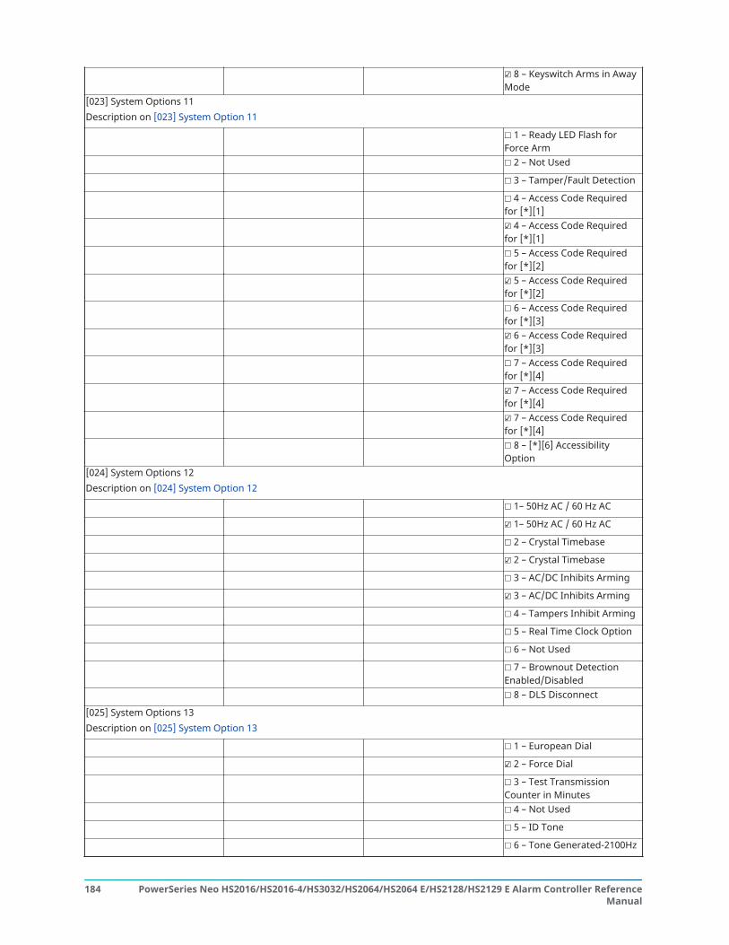
☑ 8 – Keyswitch Arms in AwayMode
[023] System Options 11Description on [023] System Option 11
☐ 1 – Ready LED Flash forForce Arm☐ 2 – Not Used
☐ 3 – Tamper/Fault Detection
☐ 4 – Access Code Requiredfor [*][1]☑ 4 – Access Code Requiredfor [*][1]☐ 5 – Access Code Requiredfor [*][2]☑ 5 – Access Code Requiredfor [*][2]☐ 6 – Access Code Requiredfor [*][3]☑ 6 – Access Code Requiredfor [*][3]☐ 7 – Access Code Requiredfor [*][4]☑ 7 – Access Code Requiredfor [*][4]☑ 7 – Access Code Requiredfor [*][4]☐ 8 – [*][6] AccessibilityOption
[024] System Options 12Description on [024] System Option 12
☐ 1– 50Hz AC / 60 Hz AC
☑ 1– 50Hz AC / 60 Hz AC
☐ 2 – Crystal Timebase
☑ 2 – Crystal Timebase
☐ 3 – AC/DC Inhibits Arming
☑ 3 – AC/DC Inhibits Arming
☐ 4 – Tampers Inhibit Arming
☐ 5 – Real Time Clock Option
☐ 6 – Not Used
☐ 7 – Brownout DetectionEnabled/Disabled☐ 8 – DLS Disconnect
[025] System Options 13Description on [025] System Option 13
☐ 1 – European Dial
☑ 2 – Force Dial
☐ 3 – Test TransmissionCounter in Minutes☐ 4 – Not Used
☐ 5 – ID Tone
☐ 6 – Tone Generated-2100Hz
PowerSeries Neo HS2016/HS2016-4/HS3032/HS2064/HS2064 E/HS2128/HS2129 E Alarm Controller ReferenceManual
184

☐ 7 – 1 Hour DLS Window
☐ 8 – FTC Audible Bell
[040] User AuthenticationDescription on [040] User Authentication
☑ 1 – User Code or Prox. Tag
☐ 2 – User Code and Prox. Tag
[041] Access Code DigitsDescription on [041] Access Code Digits
☑ 00 – 4-Digit Access Codes
☐ 01 – 6-Digit Access Codes
☐ 02 – 8-Digit Access Codes
[042] Event VerificationDescription on [042] Verified Events
01 – Burglary Verified Counter (Default: 002):
02 – Holdup Counter (Default: 002):
03 – Burglary VerificationSelection:
001 – Police Code (Default)002 – Cross Zoning003 – Sequential Detection
Auto-Arm / Disarm[151] Partition 1 Auto-Arm/DisarmDescription on [151]-[158] Partition Auto-Arm/Disarm
001 – Partition 1 Auto-ArmingTimes:
24-Hour:
(4-digit HH:MM) Sunday: Thursday:
Default: 9999 Monday: Friday:
Tuesday: Saturday:
Wednesday:
002 – Partition 1 Auto-DisarmTimes:
24-Hour:
(4-digit HH:MM) Sunday: Thursday:
Default: 9999 Monday: Friday:
Tuesday: Saturday:
Wednesday:
003 – Partition 1 Auto-Disarming Holiday Schedule:
Holiday 1: o On ☑ Off
(3-digit decimal) Holiday 2: o On ☑ Off
Holiday 3: o On ☑ Off
Holiday 4: o On ☑ Off
004 – Partition 1 Auto-Arming Pre-Alert (Default: 004):
005 – Partition 1 Auto-Arming Postpone Timer (Default: 000):
006 – Partition 1 No Activity Arming Timer (Default: 000):
185PowerSeries Neo HS2016/HS2016-4/HS3032/HS2064/HS2064 E/HS2128/HS2129 E Alarm Controller ReferenceManual
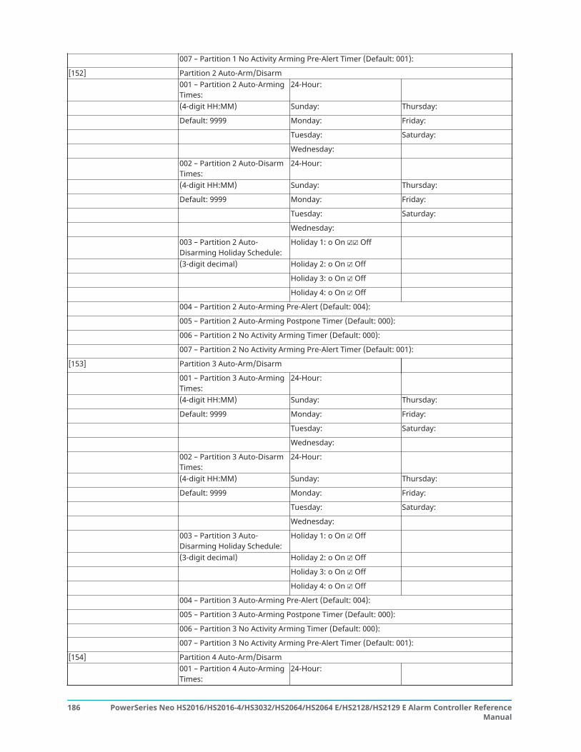
007 – Partition 1 No Activity Arming Pre-Alert Timer (Default: 001):
[152] Partition 2 Auto-Arm/Disarm001 – Partition 2 Auto-ArmingTimes:
24-Hour:
(4-digit HH:MM) Sunday: Thursday:
Default: 9999 Monday: Friday:
Tuesday: Saturday:
Wednesday:
002 – Partition 2 Auto-DisarmTimes:
24-Hour:
(4-digit HH:MM) Sunday: Thursday:
Default: 9999 Monday: Friday:
Tuesday: Saturday:
Wednesday:
003 – Partition 2 Auto-Disarming Holiday Schedule:
Holiday 1: o On ☑☑ Off
(3-digit decimal) Holiday 2: o On ☑ Off
Holiday 3: o On ☑ Off
Holiday 4: o On ☑ Off
004 – Partition 2 Auto-Arming Pre-Alert (Default: 004):
005 – Partition 2 Auto-Arming Postpone Timer (Default: 000):
006 – Partition 2 No Activity Arming Timer (Default: 000):
007 – Partition 2 No Activity Arming Pre-Alert Timer (Default: 001):
[153] Partition 3 Auto-Arm/Disarm
001 – Partition 3 Auto-ArmingTimes:
24-Hour:
(4-digit HH:MM) Sunday: Thursday:
Default: 9999 Monday: Friday:
Tuesday: Saturday:
Wednesday:
002 – Partition 3 Auto-DisarmTimes:
24-Hour:
(4-digit HH:MM) Sunday: Thursday:
Default: 9999 Monday: Friday:
Tuesday: Saturday:
Wednesday:
003 – Partition 3 Auto-Disarming Holiday Schedule:
Holiday 1: o On ☑ Off
(3-digit decimal) Holiday 2: o On ☑ Off
Holiday 3: o On ☑ Off
Holiday 4: o On ☑ Off
004 – Partition 3 Auto-Arming Pre-Alert (Default: 004):
005 – Partition 3 Auto-Arming Postpone Timer (Default: 000):
006 – Partition 3 No Activity Arming Timer (Default: 000):
007 – Partition 3 No Activity Arming Pre-Alert Timer (Default: 001):
[154] Partition 4 Auto-Arm/Disarm001 – Partition 4 Auto-ArmingTimes:
24-Hour:
PowerSeries Neo HS2016/HS2016-4/HS3032/HS2064/HS2064 E/HS2128/HS2129 E Alarm Controller ReferenceManual
186

(4-digit HH:MM) Sunday: Thursday:
Default: 9999 Monday: Friday:
Tuesday: Saturday:
Wednesday:
002 – Partition 4 Auto-DisarmTimes:
24-Hour:
(4-digit HH:MM) Sunday: Thursday:
Default: 9999 Monday: Friday:
Tuesday: Saturday:
Wednesday:
003 – Partition 4 Auto-Disarming Holiday Schedule:
Holiday 1: o On ☑ Off
(3-digit decimal) Holiday 2: o On ☑ Off
Holiday 3: o On ☑ Off
Holiday 4: o On ☑ Off
004 – Partition 4 Auto-Arming Pre-Alert (Default: 004):
005 – Partition 4 Auto-Arming Postpone Timer (Default: 000):
006 – Partition 4 No Activity Arming Timer (Default: 000):
007 – Partition 4 No Activity Arming Pre-Alert Timer (Default: 001):
[155] Partition 5 Auto-Arm/Disarm001 – Partition 5 Auto-ArmingTimes:
24-Hour:
(4-digit HH:MM) Sunday: Thursday:
Default: 9999 Monday: Friday:
Tuesday: Saturday:
Wednesday:
002 – Partition 5 Auto-DisarmTimes:
24-Hour:
(4-digit HH:MM) Sunday: Thursday:
Default: 9999 Monday: Friday:
Tuesday: Saturday:
Wednesday:
003 – Partition 2 Auto-Disarming Holiday Schedule:
Holiday 1: o On ☑ Off
(3-digit decimal) Holiday 2: o On ☑ Off
Holiday 3: o On ☑ Off
Holiday 4: o On ☑ Off
004 – Partition 5 Auto-Arming Pre-Alert (Default: 004):
005 – Partition 5 Auto-Arming Postpone Timer (Default: 000):
006 – Partition 5 No Activity Arming Timer (Default: 000):
007 – Partition 5 No Activity Arming Pre-Alert Timer (Default: 001):
[156] Partition 6 Auto-Arm/Disarm001 – Partition 6 Auto-ArmingTimes:
24-Hour:
(4-digit HH:MM) Sunday: Thursday:
Default: 9999 Monday: Friday:
Tuesday: Saturday:
187PowerSeries Neo HS2016/HS2016-4/HS3032/HS2064/HS2064 E/HS2128/HS2129 E Alarm Controller ReferenceManual

Wednesday:
002 – Partition 6 Auto-DisarmTimes:
24-Hour:
(4-digit HH:MM) Sunday: Thursday:
Default: 9999 Monday: Friday:
Tuesday: Saturday:
Wednesday:
003 – Partition 6 Auto-Disarming Holiday Schedule:
Holiday 1: o On ☑ Off
(3-digit decimal) Holiday 2: o On ☑ Off
Holiday 3: o On ☑ Off
Holiday 4: o On ☑ Off
004 – Partition 6 Auto-ArmingPre-Alert (Default: 004):005 – Partition 6 Auto-ArmingPostpone Timer (Default: 000):006 – Partition 6 No ActivityArming Timer (Default: 000):007 – Partition 6 No ActivityArming Pre-Alert Timer(Default: 001):
[157] Partition 7 Auto-Arm/Disarm001 – Partition 7 Auto-ArmingTimes:
24-Hour:
(4-digit HH:MM) Sunday: Thursday:
Default: 9999 Monday: Friday:
Tuesday: Saturday:
Wednesday:
002 – Partition 7 Auto-DisarmTimes:
24-Hour:
(4-digit HH:MM) Sunday: Thursday:
Default: 9999 Monday: Friday:
Tuesday: Saturday:
Wednesday:
003 – Partition 7 Auto-Disarming Holiday Schedule:
Holiday 1: o On ☑ Off
(3-digit decimal) Holiday 2: o On ☑ Off
Holiday 3: o On ☑ Off
Holiday 4: o On ☑ Off
004 – Partition 7 Auto-Arming Pre-Alert (Default: 004):
005 – Partition 7 Auto-Arming Postpone Timer (Default: 000):
006 – Partition 7 No Activity Arming Timer (Default: 000):
007 – Partition 7 No Activity Arming Pre-Alert Timer (Default: 001):
[158] Partition 8 Auto-Arm/Disarm001 – Partition 8 Auto-ArmingTimes:
24-Hour:
(4-digit HH:MM) Sunday: Thursday:
Default: 9999 Monday: Friday:
Tuesday: Saturday:
PowerSeries Neo HS2016/HS2016-4/HS3032/HS2064/HS2064 E/HS2128/HS2129 E Alarm Controller ReferenceManual
188

Wednesday:
002 – Partition 8 Auto-DisarmTimes:
24-Hour:
(4-digit HH:MM) Sunday: Thursday:
Default: 9999 Monday: Friday:
Tuesday: Saturday:
Wednesday:
003 – Partition 8 Auto-Disarming Holiday Schedule:
Holiday 1: o On ☑ Off
(3-digit decimal) Holiday 2: o On ☑ Off
Holiday 3: o On ☑ Off
Holiday 4: o On ☑ Off
004 – Partition 8 Auto-Arming Pre-Alert (Default: 004):
005 – Partition 8 Auto-Arming Postpone Timer (Default: 000):
006 – Partition 8 No Activity Arming Timer (Default: 000):
007 – Partition 8 No Activity Arming Pre-Alert Timer (Default: 001):
[200] Partition Mask
001 – Partition 1 to 8 EnableMask
☑ – Partition 1
o – Partition 2
Descriptions on [200] PartitionMask
o – Partition 3
o – Partition 4
o – Partition 5
o – Partition 6
o – Partition 7
o – Partition 8
Partition and Zone Assignment[201]-[208] Partition Zone Assignment
(Description on [201]-[208] Partition ZoneAssignment)[201] Partition 1 Zone Assignment [202] Partition 2 Zone Assignment
Bit 1 2 3 4 5 6 7 8 Bit 1 2 3 4 5 6 7 8
001 – 01-08 ☑ ☑ ☑ ☑ ☑ ☑ ☑ ☑ ☑ 001 – 01-08 ☐☐☐☐☐☐☐☐002 – 09-16 ☑ ☑ ☑ ☑ ☑ ☑ ☑ ☑ 002 – 09-16 ☐☐ ☐ ☐ ☐ ☐ ☐☐003 – 17-24 ☐☐ ☐ ☐ ☐ ☐ ☐☐ 003 – 17-24 ☐☐ ☐ ☐ ☐ ☐ ☐☐004 – 25-32 ☐☐☐☐☐☐☐☐ 004 – 25-32 ☐☐☐☐☐☐☐☐005 – 33-40 ☐☐☐☐☐☐☐☐ 005 – 33-40 ☐☐☐☐☐☐☐☐006 – 41-48 ☐☐ ☐ ☐ ☐ ☐ ☐☐ 006 – 41-48 ☐☐☐☐☐☐☐☐007 – 49-56 ☐☐ ☐ ☐ ☐ ☐ ☐☐ 007 – 49-56 ☐☐☐☐☐☐☐☐008 – 57-64 ☐☐☐☐☐☐☐☐ 008 – 57-64 ☐☐☐☐☐☐☐☐009 – 65-72 ☐☐☐☐☐☐☐☐ 009 – 65-72 ☐☐☐☐☐☐☐☐010 – 73-80 ☐☐☐☐☐☐☐☐ 010 – 73-80 ☐☐☐☐☐☐☐☐
189PowerSeries Neo HS2016/HS2016-4/HS3032/HS2064/HS2064 E/HS2128/HS2129 E Alarm Controller ReferenceManual

011 – 81-88 ☐☐ ☐ ☐ ☐ ☐ ☐☐ 011 – 81-88 ☐☐☐☐☐☐☐☐012 – 89-96 ☐☐☐☐☐☐☐☐ 012 – 89-96 ☐☐☐☐☐☐☐☐013 – 97-104 ☐☐ ☐ ☐ ☐ ☐ ☐☐ 013 – 97-104 ☐☐☐☐☐☐☐☐014 – 105-112 ☐☐☐☐☐☐☐☐ 014 – 105-112 ☐☐☐☐☐☐☐☐015 – 113-120 ☐☐☐☐☐☐☐☐ 015 – 113-120 ☐☐☐☐☐☐☐☐016 – 121-128 ☐☐☐☐☐☐☐☐ 016 – 121-128 ☐☐☐☐☐☐☐☐[203] Partition 3 Zone Assignment [204] Partition 4 Zone Assignment
Bit 1 2 3 4 5 6 7 8 Bit 1 2 3 4 5 6 7 8
001 – 01-08 ☐☐☐☐☐☐☐☐ 001 – 01-08 ☐☐☐☐☐☐☐☐002 – 09-16 ☐☐☐☐☐☐☐☐ 002 – 09-16 ☐☐☐☐☐☐☐☐003 – 17-24 ☐☐☐☐☐☐☐☐ 003 – 17-24 ☐☐☐☐☐☐☐☐004 – 25-32 ☐☐☐☐☐☐☐☐ 004 – 25-32 ☐☐☐☐☐☐☐☐005 – 33-40 ☐☐☐☐☐☐☐☐ 005 – 33-40 ☐☐☐☐☐☐☐☐006 – 41-48 ☐☐☐☐☐☐☐☐ 006 – 41-48 ☐☐☐☐☐☐☐☐007 – 49-56 ☐☐☐☐☐☐☐☐ 007 – 49-56 ☐☐☐☐☐☐☐☐008 – 57-64 ☐☐☐☐☐☐☐☐ 008 – 57-64 ☐☐☐☐☐☐☐☐009 – 65-72 ☐☐☐☐☐☐☐☐ 009 – 65-72 ☐☐☐☐☐☐☐☐010 – 73-80 ☐☐☐☐☐☐☐☐ 010 – 73-80 ☐☐☐☐☐☐☐☐011 – 81-88 ☐☐☐☐☐☐☐☐ 011 – 81-88 ☐☐☐☐☐☐☐☐012 – 89-96 ☐☐☐☐☐☐☐☐ 012 – 89-96 ☐☐☐☐☐☐☐☐013 – 97-104 ☐☐☐☐☐☐☐☐ 013 – 97-104 ☐☐☐☐☐☐☐☐014 – 105-112 ☐☐☐☐☐☐☐☐ 014 – 105-112 ☐☐☐☐☐☐☐☐015 – 113-120 ☐☐☐☐☐☐☐☐ 015 – 113-120 ☐☐☐☐☐☐☐☐016 – 121-128 ☐☐☐☐☐☐☐☐ 016 – 121-128 ☐☐☐☐☐☐☐☐[205] Partition 5 Zone Assignment [206] Partition 6 Zone Assignment
Bit 1 2 3 4 5 6 7 8 Bit 1 2 3 4 5 6 7 8
001 – 01-08 ☐☐☐☐☐☐☐☐ 001 – 01-08 ☐☐☐☐☐☐☐☐002 – 09-16 ☐☐☐☐☐☐☐☐ 002 – 09-16 ☐☐☐☐☐☐☐☐003 – 17-24 ☐☐☐☐☐☐☐☐ 003 – 17-24 ☐☐☐☐☐☐☐☐004 – 25-32 ☐☐☐☐☐☐☐☐ 004 – 25-32 ☐☐☐☐☐☐☐☐005 – 33-40 ☐☐☐☐☐☐☐☐ 005 – 33-40 ☐☐☐☐☐☐☐☐006 – 41-48 ☐☐☐☐☐☐☐☐ 006 – 41-48 ☐☐☐☐☐☐☐☐007 – 49-56 ☐☐☐☐☐☐☐☐ 007 – 49-56 ☐☐☐☐☐☐☐☐008 – 57-64 ☐☐☐☐☐☐☐☐ 008 – 57-64 ☐☐☐☐☐☐☐☐009 – 65-72 ☐☐☐☐☐☐☐☐ 009 – 65-72 ☐☐☐☐☐☐☐☐010 – 73-80 ☐☐☐☐☐☐☐☐ 010 – 73-80 ☐☐☐☐☐☐☐☐011 – 81-88 ☐☐☐☐☐☐☐☐ 011 – 81-88 ☐☐☐☐☐☐☐☐012 – 89-96 ☐☐☐☐☐☐☐☐ 012 – 89-96 ☐☐☐☐☐☐☐☐013 – 97-104 ☐☐☐☐☐☐☐☐ 013 – 97-104 ☐☐☐☐☐☐☐☐014 – 105-112 ☐☐☐☐☐☐☐☐ 014 – 105-112 ☐☐☐☐☐☐☐☐015 – 113-120 ☐☐☐☐☐☐☐☐ 015 – 113-120 ☐☐☐☐☐☐☐☐
PowerSeries Neo HS2016/HS2016-4/HS3032/HS2064/HS2064 E/HS2128/HS2129 E Alarm Controller ReferenceManual
190

016 – 121-128 ☐☐☐☐☐☐☐☐ 016 – 121-128 ☐☐☐☐☐☐☐☐[207] Partition 7 Zone Assignment [208] Partition 8 Zone Assignment
Bit 1 2 3 4 5 6 7 8 Bit 1 2 3 4 5 6 7 8
001 – 01-08 ☐☐☐☐☐☐☐☐ 001 – 01-08 ☐☐☐☐☐☐☐☐002 – 09-16 ☐☐☐☐☐☐☐☐ 002 – 09-16 ☐☐☐☐☐☐☐☐003 – 17-24 ☐☐☐☐☐☐☐☐ 003 – 17-24 ☐☐☐☐☐☐☐☐004 – 25-32 ☐☐☐☐☐☐☐☐ 004 – 25-32 ☐☐☐☐☐☐☐☐005 – 33-40 ☐☐☐☐☐☐☐☐ 005 – 33-40 ☐☐☐☐☐☐☐☐006 – 41-48 ☐☐☐☐☐☐☐☐ 006 – 41-48 ☐☐☐☐☐☐☐☐007 – 49-56 ☐☐☐☐☐☐☐☐ 007 – 49-56 ☐☐☐☐☐☐☐☐008 – 57-64 ☐☐☐☐☐☐☐☐ 008 – 57-64 ☐☐☐☐☐☐☐☐009 – 65-72 ☐☐☐☐☐☐☐☐ 009 – 65-72 ☐☐☐☐☐☐☐☐010 – 73-80 ☐☐☐☐☐☐☐☐ 010 – 73-80 ☐☐☐☐☐☐☐☐011 – 81-88 ☐☐☐☐☐☐☐☐ 011 – 81-88 ☐☐☐☐☐☐☐☐012 – 89-96 ☐☐☐☐☐☐☐☐ 012 – 89-96 ☐☐☐☐☐☐☐☐013 – 97-104 ☐☐☐☐☐☐☐☐ 013 – 97-104 ☐☐☐☐☐☐☐☐014 – 105-112 ☐☐☐☐☐☐☐☐ 014 – 105-112 ☐☐☐☐☐☐☐☐015 – 113-120 ☐☐☐☐☐☐☐☐ 015 – 113-120 ☐☐☐☐☐☐☐☐016 – 121-128 ☐☐☐☐☐☐☐☐ 016 – 121-128 ☐☐☐☐☐☐☐☐
Communications[300] Panel/Receiver Communications PathDescription on [300] Panel/Receiver Communication Paths
001 – Receiver 1: ☑ PSTN-Phone Line
o Alt Comm Auto Routing
o Alt Comm Rec 1
o Alt Comm Rec 2
o Alt Comm Rec 3
☐ Alt Comm Rec 4
002 – Receiver 2: ☑ PSTN-Phone Line
☐ Alt Comm Auto Routing
☐ Alt Comm Rec 1
☐ Alt Comm Rec 2
☐ Alt Comm Rec 3
☐ Alt Comm Rec 4
003 – Receiver 3: ☑ PSTN-Phone Line
☐ Alt Comm Auto Routing
☐ Alt Comm Rec 1
☐ Alt Comm Rec 2
☐ Alt Comm Rec 3
☐ Alt Comm Rec 4
004 – Receiver 4: ☑ PSTN-Phone Line
191PowerSeries Neo HS2016/HS2016-4/HS3032/HS2064/HS2064 E/HS2128/HS2129 E Alarm Controller ReferenceManual

☐ Alt Comm Auto Routing
☐ Alt Comm Rec 1
☐ Alt Comm Rec 2
☐ Alt Comm Rec 3
☐ Alt Comm Rec 4
[301] Phone Number Programming(Default: DFFFFFFFFFFFFFFFFFFFFFFFFFFFFFFF)
(32-Digit HEX) 001 – Phone Number 1 Programming:
Description on [301] Phone NumberProgramming
002 – Phone Number 2 Programming:
003 – Phone Number 3 Programming:
004 – Phone Number 4 Programming:
[304] Call Waiting Cancel String(Description on [304] Call Waiting Cancel String)
Call Waiting Cancel String (6-digit Hex; Default: DB70EF Default: FFFFFF):
[307] Zone Reporting
Description on [307] Zone Reporting (001-128 = zones 1-128)☑ 1 – Alarm
☑ 2 – Alarm Restore
☑ 3 – Tamper
☑ 4 – Tamper Restore
☑ 5 – Fault
☑ 6 – Fault Restore001 ☑☑☑☑
☑☐☐
1 2 3 45 6 7 8
002 ☑☑☑☑☑☐☐
1 2 3 45 6 7 8
003 ☑☑☑☑☑☐☐
1 2 3 45 6 7 8
004 ☑☑☑☑☑☐☐
1 2 3 45 6 7 8
005 ☑☑☑☑☑☐☐
1 2 3 45 6 7 8
006 ☑☑☑☑☑☐☐
1 2 3 45 6 7 8
007 ☑☑☑☑☑☐☐
1 2 3 45 6 7 8
008 ☑☑☑☑☑☐☐
1 2 3 45 6 7 8
009 ☑☑☑☑☑☐☐
1 2 3 45 6 7 8
010 ☑☑☑☑☑☐☐
1 2 3 45 6 7 8
011 ☑☑☑☑☑☐☐
1 2 3 45 6 7 8
012 ☑☑☑☑☑☐☐
1 2 3 45 6 7 8
013 ☑☑☑☑☑☐☐
1 2 3 45 6 7 8
014 ☑☑☑☑☑☐☐
1 2 3 45 6 7 8
015 ☑☑☑☑☑☐☐
1 2 3 45 6 7 8
016 ☑☑☑☑☑☐☐
1 2 3 45 6 7 8
017 ☑☑☑☑☑☐☐
1 2 3 45 6 7 8
018 ☑☑☑☑☑☐☐
1 2 3 45 6 7 8
019 ☑☑☑☑☑☐☐
1 2 3 45 6 7 8
020 ☑☑☑☑☑☐☐
1 2 3 45 6 7 8
PowerSeries Neo HS2016/HS2016-4/HS3032/HS2064/HS2064 E/HS2128/HS2129 E Alarm Controller ReferenceManual
192

021 ☑☑☑☑☑☐☐
1 2 3 45 6 7 8
022 ☑☑☑☑☑☐☐
1 2 3 45 6 7 8
023 ☑☑☑☑☑☐☐
1 2 3 45 6 7 8
024 ☑☑☑☑☑☐☐
1 2 3 45 6 7 8
025 ☑☑☑☑☑☐☐
1 2 3 45 6 7 8
026 ☑☑☑☑☑☐☐
1 2 3 45 6 7 8
027 ☑☑☑☑☑☐☐
1 2 3 45 6 7 8
028 ☑☑☑☑☑☐☐
1 2 3 45 6 7 8
029 ☑☑☑☑☑☐☐
1 2 3 45 6 7 8
030 ☑☑☑☑☑☐☐
1 2 3 45 6 7 8
031 ☑☑☑☑☑☐☐
1 2 3 45 6 7 8
032 ☑☑☑☑☑☐☐
1 2 3 45 6 7 8
033 ☑☑☑☑☑☐☐
1 2 3 45 6 7 8
034 ☑☑☑☑☑☐☐
1 2 3 45 6 7 8
035 ☑☑☑☑☑☐☐
1 2 3 45 6 7 8
036 ☑☑☑☑☑☐☐
1 2 3 45 6 7 8
037 ☑☑☑☑☑☐☐
1 2 3 45 6 7 8
038 ☑☑☑☑☑☐☐
1 2 3 45 6 7 8
039 ☑☑☑☑☑☐☐
1 2 3 45 6 7 8
040 ☑☑☑☑☑☐☐
1 2 3 45 6 7 8
041 ☑☑☑☑☑☐☐
1 2 3 45 6 7 8
042 ☑☑☑☑☑☐☐
1 2 3 45 6 7 8
043 ☑☑☑☑☑☐☐
1 2 3 45 6 7 8
044 ☑☑☑☑☑☐☐
1 2 3 45 6 7 8
045 ☑☑☑☑☑☐☐
1 2 3 45 6 7 8
046 ☑☑☑☑☑☐☐
1 2 3 45 6 7 8
047 ☑☑☑☑☑☐☐
1 2 3 45 6 7 8
048 ☑☑☑☑☑☐☐
1 2 3 45 6 7 8
049 ☑☑☑☑☑☐☐
1 2 3 45 6 7 8
050 ☑☑☑☑☑☐☐
1 2 3 45 6 7 8
051 ☑☑☑☑☑☐☐
1 2 3 45 6 7 8
052 ☑☑☑☑☑☐☐
1 2 3 45 6 7 8
053 ☑☑☑☑☑☐☐
1 2 3 45 6 7 8
054 ☑☑☑☑☑☐☐
1 2 3 45 6 7 8
055 ☑☑☑☑☑☐☐
1 2 3 45 6 7 8
056 ☑☑☑☑☑☐☐
1 2 3 45 6 7 8
057 ☑☑☑☑☑☐☐
1 2 3 45 6 7 8
058 ☑☑☑☑☑☐☐
1 2 3 45 6 7 8
059 ☑☑☑☑☑☐☐
1 2 3 45 6 7 8
060 ☑☑☑☑☑☐☐
1 2 3 45 6 7 8
061 ☑☑☑☑☑☐☐
1 2 3 45 6 7 8
062 ☑☑☑☑☑☐☐
1 2 3 45 6 7 8
063 ☑☑☑☑☑☐☐
1 2 3 45 6 7 8
064 ☑☑☑☑☑☐☐
1 2 3 45 6 7 8
065 ☑☑☑☑☑☐☐
1 2 3 45 6 7 8
066 ☑☑☑☑☑☐☐
1 2 3 45 6 7 8
067 ☑☑☑☑☑☐☐
1 2 3 45 6 7 8
068 ☑☑☑☑☑☐☐
1 2 3 45 6 7 8
069 ☑☑☑☑☑☐☐
1 2 3 45 6 7 8
070 ☑☑☑☑☑☐☐
1 2 3 45 6 7 8
193PowerSeries Neo HS2016/HS2016-4/HS3032/HS2064/HS2064 E/HS2128/HS2129 E Alarm Controller ReferenceManual

071 ☑☑☑☑☑☐☐
1 2 3 45 6 7 8
072 ☑☑☑☑☑☐☐
1 2 3 45 6 7 8
073 ☑☑☑☑☑☐☐
1 2 3 45 6 7 8
074 ☑☑☑☑☑☐☐
1 2 3 45 6 7 8
075 ☑☑☑☑☑☐☐
1 2 3 45 6 7 8
076 ☑☑☑☑☑☐☐
1 2 3 45 6 7 8
077 ☑☑☑☑☑☐☐
1 2 3 45 6 7 8
078 ☑☑☑☑☑☐☐
1 2 3 45 6 7 8
079 ☑☑☑☑☑☐☐
1 2 3 45 6 7 8
080 ☑☑☑☑☑☐☐
1 2 3 45 6 7 8
081 ☑☑☑☑☑oo
1 2 3 45 6 7 8
082 ☑☑☑☑☑oo
1 2 3 45 6 7 8
083 ☑☑☑☑☑oo
1 2 3 45 6 7 8
084 ☑☑☑☑☑☐☐
1 2 3 45 6 7 8
085 ☑☑☑☑☑☐☐
1 2 3 45 6 7 8
086 ☑☑☑☑☑☐☐
1 2 3 45 6 7 8
087 ☑☑☑☑☑☐☐
1 2 3 45 6 7 8
088 ☑☑☑☑☑☐☐
1 2 3 45 6 7 8
089 ☑☑☑☑☑☐☐
1 2 3 45 6 7 8
090 ☑☑☑☑☑☐☐
1 2 3 45 6 7 8
091 ☑☑☑☑☑☐☐
1 2 3 45 6 7 8
092 ☑☑☑☑☑☐☐
1 2 3 45 6 7 8
093 ☑☑☑☑☑☐☐
1 2 3 45 6 7 8
094 ☑☑☑☑☑☐☐
1 2 3 45 6 7 8
095 ☑☑☑☑☑☐☐
1 2 3 45 6 7 8
096 ☑☑☑☑☑☐☐
1 2 3 45 6 7 8
097 ☑☑☑☑☑☐☐
1 2 3 45 6 7 8
098 ☑☑☑☑☑☐☐
1 2 3 45 6 7 8
099 ☑☑☑☑☑☐☐
1 2 3 45 6 7 8
100 ☑☑☑☑☑☐☐
1 2 3 45 6 7 8
101 ☑☑☑☑☑☐☐
1 2 3 45 6 7 8
102 ☑☑☑☑☑☐☐
1 2 3 45 6 7 8
103 ☑☑☑☑☑☐☐
1 2 3 45 6 7 8
104 ☑☑☑☑☑☐☐
1 2 3 45 6 7 8
105 ☑☑☑☑☑☐☐
1 2 3 45 6 7 8
106 ☑☑☑☑☑☐☐
1 2 3 45 6 7 8
107 ☑☑☑☑☑☐☐
1 2 3 45 6 7 8
108 ☑☑☑☑☑☐☐
1 2 3 45 6 7 8
109 ☑☑☑☑☑☐☐
1 2 3 45 6 7 8
110 ☑☑☑☑☑☐☐
1 2 3 45 6 7 8
111 ☑☑☑☑☑☐☐
1 2 3 45 6 7 8
112 ☑☑☑☑☑☐☐
1 2 3 45 6 7 8
113 ☑☑☑☑☑☐☐
1 2 3 45 6 7 8
114 ☑☑☑☑☑☐☐
1 2 3 45 6 7 8
115 ☑☑☑☑☑☐☐
1 2 3 45 6 7 8
PowerSeries Neo HS2016/HS2016-4/HS3032/HS2064/HS2064 E/HS2128/HS2129 E Alarm Controller ReferenceManual
194

116 ☑☑☑☑☑☐☐
1 2 3 45 6 7 8
117 ☑☑☑☑☑☐☐
1 2 3 45 6 7 8
118 ☑☑☑☑☑☐☐
1 2 3 45 6 7 8
119 ☑☑☑☑☑☐☐
1 2 3 45 6 7 8
120 ☑☑☑☑☑☐☐
1 2 3 45 6 7 8
121 ☑☑☑☑☑☐☐
1 2 3 45 6 7 8
122 ☑☑☑☑☑☐☐
1 2 3 45 6 7 8
123 ☑☑☑☑☑☐☐
1 2 3 45 6 7 8
124 ☑☑☑☑☑☐☐
1 2 3 45 6 7 8
125 ☑☑☑☑☑☐☐
1 2 3 45 6 7 8
126 ☑☑☑☑☑☐☐
1 2 3 45 6 7 8
127 ☑☑☑☑☑☐☐
1 2 3 45 6 7 8
128 ☑☑☑☑☑☐☐
1 2 3 45 6 7 8
195PowerSeries Neo HS2016/HS2016-4/HS3032/HS2064/HS2064 E/HS2128/HS2129 E Alarm Controller ReferenceManual

[308] Event Reporting
Description on001 – Miscellaneous Alarm 1 ☑1 – Duress Alarm
☑ 2 – Opening After Alarm
☑ 3 – Recent Closing Alarm
☑ 4 – Zone ExpanderSupervisory Alarm
☑ 5 – Zone ExpanderSupervisory Alarm Restore
☑ 6 – Burglary Verified
☑ 7 – Burglary Not VerifiedAlarm
☑ 8 – Alarm Cancel002 – Miscellaneous Alarm 2 ☑ 1 – Holdup Verified Alarm
011 – Priority Alarms 1 ☑ 1 – Keypad Fire Alarm-F Key
☑ 2 – Keypad Fire Restore
☑ 3 – Keypad Medical Alarm-MKey
☑ 4 – Keypad Medical Restore
☑ 5 – Keypad Panic Alarm-P KeyAlarm
☑ 6 – Keypad Panic Restore
☑ 7 – Auxiliary Input Alarm
☑ 8 – Auxiliary Input AlarmRestore
021 – Fire Alarms 1 ☑ 3 – PGM 2 2-Wire Alarm
☑ 4 – PGM 2 2-Wire AlarmRestore
101 – Tamper Events ☑ 3 – Module Tamper
☑ 4 – Module Tamper Restore
☑ 5 – Keypad Lockout
☑ 7 – Remote Lockout
PowerSeries Neo HS2016/HS2016-4/HS3032/HS2064/HS2064 E/HS2128/HS2129 E Alarm Controller ReferenceManual
196

[308] Event Reporting
Description on201 – Open/Close Events 1 ☑ 1 – User Closing
☑ 2 – User Opening
☑ 5 – Special Closing
☑☑ 6 – Special Opening
☑ 7 – Keyswitch Opening
☑ 8 – Keyswitch Closing202 – Open/Close Events 2 ☑ 1 – Automatic Closing
☑ 2 – Automatic Disarm
☑ 3 – Auto Arm Cancellation/Postpone
211 – Miscellaneous Open/Close Events
☑ 1 – Late to Close
☑ 2 – Late to Open
☑ 5 – Exit Fault221 – Bypass Events ☑ 1 – Zone Bypass
☑ 2 – Zone Unbypass
☑ 3 – Partial Closing301 – Panel Events 1 ☑o 1 – Panel AC Fail Trouble
☑o 2 – Panel AC Fail Restore
☑ 3 – Panel Low Battery Trouble
☑ 4 – Panel Low Battery TroubleRestore
☑ 5 – Panel Battery AbsentTrouble
☑ 6 – Panel Battery AbsentTrouble Restore
197PowerSeries Neo HS2016/HS2016-4/HS3032/HS2064/HS2064 E/HS2128/HS2129 E Alarm Controller ReferenceManual

[308] Event Reporting
Description on302 – Panel Events 2 ☑ 1 – Bell Circuit Trouble
☑ 2 – Bell Circuit TroubleRestore
☑ 3 – Telephone Line Trouble
☑ 4 – Telephone Line TroubleRestore
☑ 5 – Auxiliary Trouble
☑ 6 – Auxiliary Trouble Restore305 – Panel Events 5 ☑ 3 – PGM 2 2-Wire Trouble
☑ 4 – PGM 2 2-Wire TroubleRestore
311 – Maintenance Events 1 ☑ 1 – RF Jam Trouble
☑ 2 – RF Jam Trouble Restore
☑ 3 – Fire Trouble
☑ 4 – Fire Trouble Restore
☑ 5 – Cold Start
☑ 6 – Delinquency
☑ 6 – Delinquency
☑ 7 – Self Test Trouble
☑ 8 – Self Test Trouble Restore
PowerSeries Neo HS2016/HS2016-4/HS3032/HS2064/HS2064 E/HS2128/HS2129 E Alarm Controller ReferenceManual
198

[308] Event Reporting
Description on312 – Maintenance Events 2
☐ 1 – Installer Lead IN
☐ 2 – Installer Lead OUT
☐ 3 – DLS Lead IN
☐ 4 – DLS Lead OUT
☐ 5 – SA Lead IN
☐ 6 – SA Lead OUT
☐ 7 – Event Buffer 75% Full
☐ 1 – Installer Lead IN
☐ 2 – Installer Lead OUT
☐ 3 – DLS Lead IN
☐ 4 – DLS Lead OUT
☐ 5 – SA Lead IN
☑ 6 – SA Lead OUT
☑ 7 – Event Buffer 75% Full313 – Maintenance Events 3 ☑ 1 – Firmware Update Begin
☑ 2 – Firmware UpdateSuccessful
☑ 3 – Firmware Update Fail314 – Maintenance Events 4 ☑ 1 – Gas Trouble
☑ 2 – Gas Trouble Restore
☑ 3 – Heat Trouble
☑ 4 – Heat Trouble Restore
☑ 5 – Freeze Trouble
☑ 6 – Freeze Trouble Restore
☑ 7 – Probe DisconnectedTrouble
☑ 8 – Probe DisconnectedRestore
199PowerSeries Neo HS2016/HS2016-4/HS3032/HS2064/HS2064 E/HS2128/HS2129 E Alarm Controller ReferenceManual

[308] Event Reporting
Description on321 – Receiver Events ☑ 2 – Receiver 1 FTC Restore
☑ 4 – Receiver 2 FTC Restore
☑6 – Receiver 3 FTC Restore
☑
☑ 8 – Receiver 4 FTC Restore331 – Module Events 1 ☑ 1 – Module AC Trouble
☑ 2 – Module AC TroubleRestore
☑ 3 – Module Battery Trouble
☑ 4 – Module Battery TroubleRestore
☑ 5 – Module Battery Absent
☑ 6 – Module Battery AbsentRestore
332 – Module Events 2 ☑ 1 – Module Low VoltageTrouble
☑ 2 – Module Low VoltageRestore
☑ 3 – Module Supervisory
☑ 4 – Module SupervisoryRestore
☑ 5 – Module Aux Trouble
☑ 6 – Module Aux TroubleRestore
335 – Module Events 5 ☑ 1 – Output 1 Fault
☑ 2 – Output 1 Fault Restore
PowerSeries Neo HS2016/HS2016-4/HS3032/HS2064/HS2064 E/HS2128/HS2129 E Alarm Controller ReferenceManual
200

[308] Event Reporting
Description on351 – Alternate
Communicator 1
☑ 1 – Alt. Comm. Module CommFault
☑ 2 – Alt. Comm. Module CommFault Restore
☑ 7 – Alt. Comm. Radio/SIMFailure
☑8 – Alt. Comm. Radio/SIMFailure Restore
352 – Alternate
Communicator 2
☑ 1 – Alt. Comm. Network Fault
☑ 2 – Alt. Comm. Network FaultRestore
☑ 5 – Alt. Comm. EthernetTrouble
☑ 6 – Alt. Comm. EthernetTrouble Restore
354 – Alternate
Communicator 4
☑ 1 – Alt. Comm Receiver 1Trouble
☑ 2 – Alt. Comm Receiver 1Restore
☑ 3 – Alt. Comm Receiver 2Trouble
☑ 4 – Alt. Comm Receiver 2Restore
☑ 5 – Alt. Comm Receiver 3Trouble
☑ 6 – Alt. Comm Receiver 3Restore
☑ 7 – Alt. Comm Receiver 4Trouble
☑ 8 – Alt. Comm Receiver 4Restore
201PowerSeries Neo HS2016/HS2016-4/HS3032/HS2064/HS2064 E/HS2128/HS2129 E Alarm Controller ReferenceManual

[308] Event Reporting
Description on355 – Alternate Communicator5
☑ 1 – Alt. Comm Receiver 1Supervision Failure
☑ 2 – Alt. Comm Receiver 1Supervision Restore
☑ 3 – Alt. Comm Receiver 2Supervision Failure
☑ 4 – Alt. Comm Receiver 2Supervision Restore
☑ 5 – Alt. Comm Receiver 3Supervision Failure
☑ 6 – Alt. Comm Receiver 3Supervision Restore
☑ 7 – Alt. Comm Receiver 4Supervision Failure
☑ 8 – Alt. Comm Receiver 4Supervision Restore
361 – Wireless Device Events ☑ 1 – Device AC Fail
☑ 2 – Device AC Restore
☑ 3 – Device Low Battery
☑ 4 – Device Low BatteryRestore
☑ 5 – Device Fault
☑ 6 – Device Fault Restore401 – System Test Events ☑ 1 – Walk Test Start
☑ 2 – Walk Test End
☑ 3 – Periodic TestTransmission
☑ 4 – Periodic TestTransmission with Trouble
☑ 5 – System Test
PowerSeries Neo HS2016/HS2016-4/HS3032/HS2064/HS2064 E/HS2128/HS2129 E Alarm Controller ReferenceManual
202

Call Directions[309] System Call DirectionDescription on [309] System Call Direction
001 – Maintenance Events: ☑ Receiver #1 ☐ Receiver #3
☐ Receiver #2 ☐ Receiver #4
002 – Test TransmissionEvents:
☑ Receiver #1 ☐ Receiver #3
☐ Receiver #2 ☐ Receiver #4
[310] Account Codes(4-Digit HEX; Default FFFF)
000 – System Account Code (6-digit Hex; Default: FFFFFF):
001 – Partition 1 Account Code:
002 – Partition 2 Account Code:
003 – Partition 3 Account Code:
004 – Partition 4 Account Code:
005 – Partition 5 Account Code:
006 – Partition 6 Account Code:
007 – Partition 7 Account Code:
008 – Partition 8 Account Code:
[311] Partition 1 Call DirectionsDescription on [311]-[318] Partition Call Directions
001 – Partition 1 Alarm/Restore:
☑ Receiver #1 ☐ Receiver #3
☐☑ Receiver #2 ☐ Receiver #4
002 – Partition 1 Tamper/Restore:
☑ Receiver #1 ☐ Receiver #3
☐ ☑ Receiver #2 ☐ Receiver #4
003 – Partition 1 Opening/Closing:
☐☑☑ Receiver #1 ☐ Receiver #3
☐ Receiver #2 ☐ Receiver #4
[312] Partition 2 Call Directions001 – Partition 2 Alarm/Restore:
☑ Receiver #1 ☐ Receiver #3
☐ Receiver #2 ☐ Receiver #4
002 – Partition 2 Tamper/Restore:
☑ Receiver #1 ☐ Receiver #3
☐ Receiver #2 ☐ Receiver #4
003 – Partition 2 Opening/Closing:
☐ Receiver #1 ☐ Receiver #3
☐ Receiver #2 ☐ Receiver #4
[313] Partition 3 Call Directions001 – Partition 3 Alarm/Restore:
☑ Receiver #1 ☐ Receiver #3
☐ Receiver #2 ☐ Receiver #4
002 – Partition 3 Tamper/Restore:
☑ Receiver #1 ☐ Receiver #3
☐ Receiver #2 ☐ Receiver #4
003 – Partition 3 Opening/Closing:
☐ Receiver #1 ☐ Receiver #3
203PowerSeries Neo HS2016/HS2016-4/HS3032/HS2064/HS2064 E/HS2128/HS2129 E Alarm Controller ReferenceManual

☐ Receiver #2 ☐ Receiver #4
[314] Partition 4 Call Directions001 – Partition 4 Alarm/Restore:
☑ Receiver #1 ☐ Receiver #3
☐ Receiver #2 ☐ Receiver #4
002 – Partition 4 Tamper/Restore:
☑ Receiver #1 ☐ Receiver #3
☐ Receiver #2 ☐ Receiver #4
003 – Partition 4 Opening/Closing:
☐ Receiver #1 ☐ Receiver #3
☐ Receiver #2 ☐ Receiver #4
[315] Partition 5 Call Directions001 – Partition 5 Alarm/Restore:
☑ Receiver #1 ☐ Receiver #3
☐ Receiver #2 ☐ Receiver #4
002 – Partition 5 Tamper/Restore:
☐ Receiver #1 ☐ Receiver #3
☐ Receiver #2 ☐ Receiver #4
003 – Partition 5 Opening/Closing:
☐ Receiver #1 ☐ Receiver #3
☐ Receiver #2 ☐ Receiver #4
[316] Partition 6 Call Directions001 – Partition 6 Alarm/Restore:
☑ Receiver #1 ☐ Receiver #3
☐ Receiver #2 ☐ Receiver #4
002 – Partition 6 Tamper/Restore:
☑ Receiver #1 ☐ Receiver #3
☐ Receiver #2 ☐ Receiver #4
003 – Partition 6 Opening/Closing:
☐ Receiver #1 ☐ Receiver #3
☐ Receiver #2 ☐ Receiver #4
[317] Partition 7 Call Directions001 – Partition 7 Alarm/Restore:
☑ Receiver #1 ☐ Receiver #3
☐ Receiver #2 ☐☐ Receiver #4
002 – Partition 7 Tamper/Restore:
☑ Receiver #1 ☐ Receiver #3
☐ Receiver #2 ☐ Receiver #4
003 – Partition 7 Opening/Closing:
☐ Receiver #1 ☐ Receiver #3
☐ Receiver #2 ☐ Receiver #4
[318] Partition 8 Call Directions
001 – Partition 8 Alarm/Restore:
☑ Receiver #1 ☐ Receiver #3
☐☐ Receiver #2 o Receiver #4
002 – Partition 8 Tamper/Restore:
☑ Receiver #1 ☐ Receiver #3
☐ Receiver #2 ☐ Receiver #4
003 – Partition 8 Opening/Closing:
☐ Receiver #1 ☐ Receiver #3
☐ Receiver #2 ☐ Receiver #4
PowerSeries Neo HS2016/HS2016-4/HS3032/HS2064/HS2064 E/HS2128/HS2129 E Alarm Controller ReferenceManual
204

[350] Communicator FormatsDescription on [350] Communicator Formats
(2-Digit decimal) 001 – Receiver 1: 03 003 – Receiver 3: 03
Range: 03= Contact ID, 04= SIA(Default)
002 – Receiver 2: 03 004 – Receiver 4: 03
[377] Communication Variables(3-digit decimal); Range: 000-255 attempts unless otherwise notedDescription on [377] Communication Variables
001 – Swinger Shutdown Attempts: Alarms and Restore (000-014):
Default: 003002 Tampers and Restore:
(CP-01 Default: 002) Maintenance and Restore:
002 – Communication Delays: Communication Zone Delay (Default: 000Default: 030):AC Failure Communication Delay(Default:030 minutes/Hours):TLM Trouble Delay Default: 010 checksDefault:002 checks:Wireless Zone Low Bat. TransmissionDelay (Default: 007 days):Delinquency Transmission Cycle Delay(Default: 030000 days/hours):Communications Cancel Window(Default: 000 minutes Default: 005minutes):
003 – Periodic Test Transmission Cycle (Default:030; UL:007 hours/days):
004 – Periodic Test Transmission Time of Day (Default: 9999; UL:0445):
011 – Maximum Dialing Attempts: (Default: 005):
012 – Delay Between PSTN Attempts: (Default: 003 seconds):
013 – Delay Between Force Attempts: (Default: 020 seconds):
014 – Post Dial Wait for Handshake: (Range: 001-255; Default: 040 Seconds;UL=45):015 – IP/GS Wait for Ack: (Range: 001-255; Default: 060 seconds):
016 – IP/Cellular Fault Check Timer: (Range: 003-255; Default: 010):
[380] Communicator Option 11 – ☐ Communications Enabled
2 – ☐ Restore on Bell Time-out
Description on [380] CommunicatorOption 1
3 – ☐ Pulse Dialing
4 – ☐ Pulse Dial after 5th Attempt
5 – ☐ Parallel Communications
6 – ☐ Alternate Dial (N.A.)
6 – ☐ Alternate Dial (EN)
7 – ☐ Reduced Dialing Attempts
8 – ☐ Activity Delinquency
[381] Communicator Option 21 – ☐ Keypad Ringback
2 – ☐ Bell Ringback
4 – ☐ Closing Confirmation
205PowerSeries Neo HS2016/HS2016-4/HS3032/HS2064/HS2064 E/HS2128/HS2129 E Alarm Controller ReferenceManual
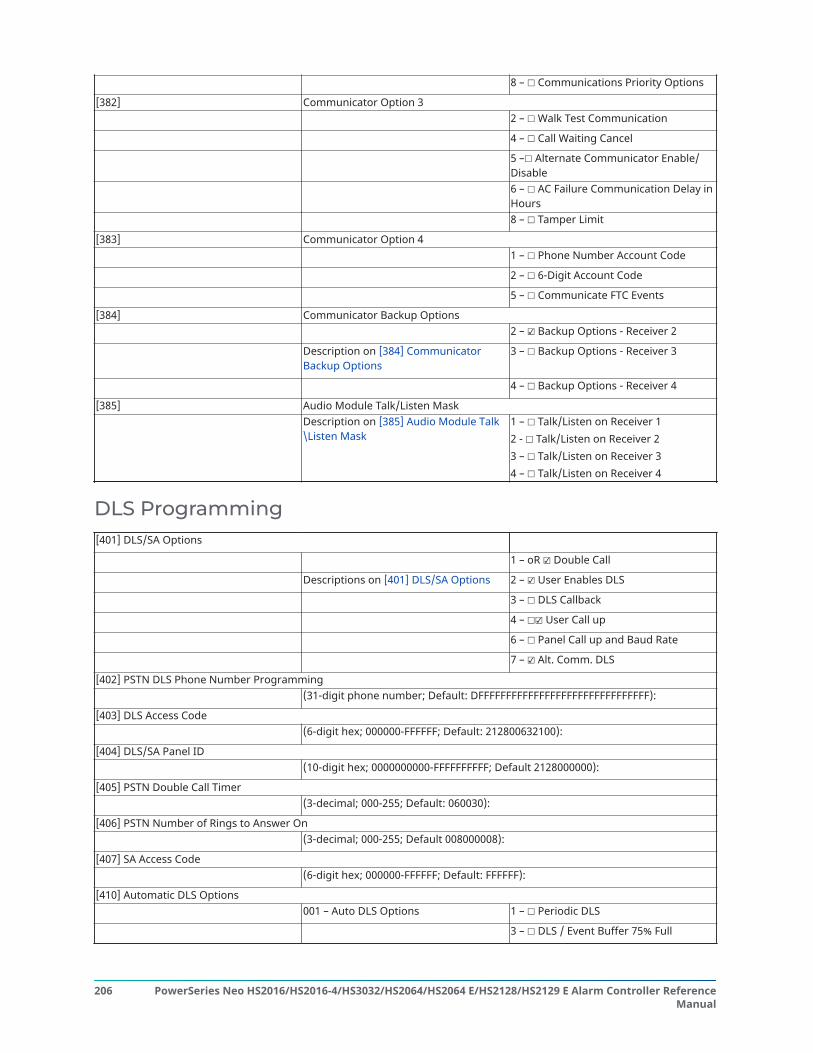
8 – ☐ Communications Priority Options
[382] Communicator Option 32 – ☐ Walk Test Communication
4 – ☐ Call Waiting Cancel
5 –☐ Alternate Communicator Enable/Disable6 – ☐ AC Failure Communication Delay inHours8 – ☐ Tamper Limit
[383] Communicator Option 41 – ☐ Phone Number Account Code
2 – ☐ 6-Digit Account Code
5 – ☐ Communicate FTC Events
[384] Communicator Backup Options2 – ☑ Backup Options - Receiver 2
Description on [384] CommunicatorBackup Options
3 – ☐ Backup Options - Receiver 3
4 – ☐ Backup Options - Receiver 4
[385] Audio Module Talk/Listen MaskDescription on [385] Audio Module Talk\Listen Mask
1 – ☐ Talk/Listen on Receiver 12 - ☐ Talk/Listen on Receiver 23 – ☐ Talk/Listen on Receiver 34 – ☐ Talk/Listen on Receiver 4
DLS Programming[401] DLS/SA Options
1 – oR ☑ Double Call
Descriptions on [401] DLS/SA Options 2 – ☑ User Enables DLS
3 – ☐ DLS Callback
4 – ☐☑ User Call up
6 – ☐ Panel Call up and Baud Rate
7 – ☑ Alt. Comm. DLS
[402] PSTN DLS Phone Number Programming(31-digit phone number; Default: DFFFFFFFFFFFFFFFFFFFFFFFFFFFFFFF):
[403] DLS Access Code(6-digit hex; 000000-FFFFFF; Default: 212800632100):
[404] DLS/SA Panel ID(10-digit hex; 0000000000-FFFFFFFFFF; Default 2128000000):
[405] PSTN Double Call Timer(3-decimal; 000-255; Default: 060030):
[406] PSTN Number of Rings to Answer On(3-decimal; 000-255; Default 008000008):
[407] SA Access Code(6-digit hex; 000000-FFFFFF; Default: FFFFFF):
[410] Automatic DLS Options001 – Auto DLS Options 1 – ☐ Periodic DLS
3 – ☐ DLS / Event Buffer 75% Full
PowerSeries Neo HS2016/HS2016-4/HS3032/HS2064/HS2064 E/HS2128/HS2129 E Alarm Controller ReferenceManual
206

8 – ☐ DLS on Programming Change
002 – Periodic DLS Days (3-digit decimal; 000-255; Default: 000 days):
003 – Periodic DLS Time (4-digit decimal; HH:MM; 0000-2359; Default: 0000):
007 – Delay Call Window Start (4-digitdecimal; 0000-2359; HH:MM)
1 – 0000 Delay Call Window Start
Default: 0000 2 – 0000 Delay Call Window End
Virtual Inputs[560] Virtual Inputs
(3 digit decimal) 001 - Virtual Input 1: 017 - Virtual Input 17:
002 - Virtual Input 2: 018 - Virtual Input 18:
Description on Virtual Inputs 003 - Virtual Input 3: 019 - Virtual Input 19:
Default: 000 004 - Virtual Input 4: 020 - Virtual Input 20:
005 - Virtual Input 5: 021 - Virtual Input 21:
006 - Virtual Input 6: 022 - Virtual Input 22:
007 - Virtual Input 7: 023 - Virtual Input 23:
008 - Virtual Input 8: 024 - Virtual Input 24:
009 - Virtual Input 9: 025 - Virtual Input 25:
010 - Virtual Input 10: 026 - Virtual Input 26:
011 - Virtual Input 11: 027 - Virtual Input 27:
012 - Virtual Input 12: 028 - Virtual Input 28:
013 - Virtual Input 13: 029 - Virtual Input 29:
014 - Virtual Input 14: 030 - Virtual Input 30:
015 - Virtual Input 15: 031 - Virtual Input 31:
016 - Virtual Input 16: 032 - Virtual Input 32:
Schedule Programming[601] Programming Schedule 1Description on [601]-[604] Schedule Labels
Interval 1 101 – Start Time: 102 – End Time:
103 – Days Assignment: 104 – HolidayAssignment:
(4- digit decimal) 01 – ☐ Sunday ☐ Holiday 1
HH:MM 02 – ☐ Monday ☐ Holiday 2
to HH:MM 03 – ☐ Tuesday ☐ Holiday 3
Default: 0000 04 – ☐ Wednesday ☐ Holiday 4
05 – ☐ Thursday
06 – ☐ Friday
07 – ☐ Saturday
Interval 2 201 – Start Time: 202 – End Time:
203 – Days Assignment: 204 – HolidayAssignment:
(4- digit decimal) 01 – ☐ Sunday ☐ Holiday 1
HH:MM 02 – ☐ Monday ☐ Holiday 2
to HH:MM 03 – ☐ Tuesday ☐ Holiday 3
207PowerSeries Neo HS2016/HS2016-4/HS3032/HS2064/HS2064 E/HS2128/HS2129 E Alarm Controller ReferenceManual

Default: 0000 04 – ☐ Wednesday ☐ Holiday 4
05 – ☐ Thursday
06 – ☐ Friday
07 – ☐ Saturday
Interval 3 301 – Start Time: 302 – End Time:
303 – Days Assignment: 304 – HolidayAssignment:
(4- digit decimal) 01 – ☐ Sunday ☐ Holiday 1
HH:MM 02 – ☐ Monday ☐ Holiday 2
to HH:MM 03 – ☐ Tuesday ☐ Holiday 3
Default: 0000 04 – ☐ Wednesday ☐ Holiday 4
05 – ☐ Thursday
06 – ☐ Friday
07 – ☐ Saturday
Interval 4 401 – Start Time: 402 – End Time:
403 – Days Assignment: 404 – HolidayAssignment:
(4- digit decimal) 01 – ☐ Sunday ☐ Holiday 1
HH:MM 02 – ☐ Monday ☐ Holiday 2
to HH:MM 03 – ☐ Tuesday ☐ Holiday 3
Default: 0000 04 – ☐ Wednesday ☐ Holiday 4
05 – ☐ Thursday
06 – ☐ Friday
07 – ☐ Saturday
[602] Programming Schedule 2Interval 1 101 – Start Time: 102 – End Time:
103 – Days Assignment: 104 – HolidayAssignment:
(4- digit decimal) 01 – ☐ Sunday ☐ Holiday 1
HH:MM 02 – ☐ Monday ☐ Holiday 2
t☐ HH:MM 03 – ☐ Tuesday ☐ Holiday 3
Default: 0000 04 –☐Wednesday ☐ Holiday 4
05 – ☐ Thursday
06 – ☐ Friday
07 – ☐ Saturday
Interval 2 201 – Start Time: 202 – End Time:
203 – Days Assignment: 204 – HolidayAssignment:
(4- digit decimal) 01 – ☐ Sunday ☐ Holiday 1
HH:MM 02 – ☐ Monday ☐ Holiday 2
to HH:MM 03 – ☐ Tuesday ☐ Holiday 3
Default: 0000 04 – ☐ Wednesday ☐ Holiday 4
05 – ☐ Thursday
06 – ☐ Friday
07 – ☐ Saturday
Interval 3 301 – Start Time: 302 – End Time:
PowerSeries Neo HS2016/HS2016-4/HS3032/HS2064/HS2064 E/HS2128/HS2129 E Alarm Controller ReferenceManual
208

303 – Days Assignment: 304 – HolidayAssignment:
(4- digit decimal) 01 – ☐ Sunday ☐ Holiday 1
HH:MM 02 – ☐ Monday ☐ Holiday 2
to HH:MM 03 – ☐ Tuesday ☐ Holiday 3
Default: 0000 04 – ☐ Wednesday ☐ Holiday 4
05 – ☐ Thursday
06 – ☐ Friday
07 – ☐ Saturday
Interval 4 401 – Start Time: 402 – End Time:
403 – Days Assignment: 404 – HolidayAssignment:
(4- digit decimal) 01 – ☐ Sunday ☐ Holiday 1
HH:MM 02 – ☐ Monday ☐ Holiday 2
to HH:MM 03 – ☐ Tuesday ☐ Holiday 3
Default: 0000 04 – ☐ Wednesday ☐ Holiday 4
05 – ☐ Thursday
06 – ☐ Friday
07 – ☐ Saturday
[603] Programming Schedule 3Interval 1 101 – Start Time: 102 – End Time:
103 – Days Assignment: 104 – HolidayAssignment:
(4- digit decimal) 01 – ☐ Sunday ☐ Holiday 1
HH:MM 02 – ☐ Monday ☐ Holiday 2
to HH:MM 03 – ☐ Tuesday ☐ Holiday 3
Default: 0000 04 – ☐ Wednesday ☐ Holiday 4
05 – ☐ Thursday
06 – ☐ Friday
07 – ☐ Saturday
Interval 2 201 – Start Time: 202 – End Time:
203 – Days Assignment: 204 – HolidayAssignment:
(4- digit decimal) 01 – ☐ Sunday ☐ Holiday 1
HH:MM 02 – ☐ Monday ☐ Holiday 2
to HH:MM 03 – ☐ Tuesday ☐ Holiday 3
Default: 0000 04 – ☐ Wednesday ☐ Holiday 4
05 – ☐ Thursday
06 – ☐ Friday
07 – ☐ Saturday
Interval 3 301 – Start Time: 302 – End Time:
303 – Days Assignment: 304 – HolidayAssignment:
(4- digit decimal) 01 – ☐ Sunday ☐ Holiday 1
HH:MM 02 – ☐ Monday ☐ Holiday 2
to HH:MM 03 – ☐ Tuesday ☐ Holiday 3
Default: 0000 04 – ☐ Wednesday ☐ Holiday 4
209PowerSeries Neo HS2016/HS2016-4/HS3032/HS2064/HS2064 E/HS2128/HS2129 E Alarm Controller ReferenceManual

05 – ☐ Thursday
06 – ☐ Friday
07 – ☐ Saturday
Interval 4 401 – Start Time: 402 – End Time:
403 – Days Assignment: 404 – HolidayAssignment:
(4- digit decimal) 01 – ☐ Sunday ☐ Holiday 1
HH:MM 02 – ☐ Monday ☐ Holiday 2
to HH:MM 03 – ☐ Tuesday ☐ Holiday 3
Default: 0000 04 – ☐ Wednesday ☐ Holiday 4
05 – ☐ Thursday
06 – ☐ Friday
07 – ☐ Saturday
[604] Programming Schedule 4Interval 1 101 – Start Time: 102 – End Time:
103 – Days Assignment: 104 – HolidayAssignment:
(4- digit decimal) 01 – ☐ Sunday ☐ Holiday 1
HH:MM to HH:MM 02 – ☐ Monday ☐ Holiday 2
Default: 0000 03 – ☐ Tuesday ☐ Holiday 3
04 – ☐ Wednesday ☐ Holiday 4
05 – ☐ Thursday
06 – ☐ Friday
07 – ☐ Saturday
Interval 2 201 – Start Time: 202 – End Time:
203 – Days Assignment: 204 – HolidayAssignment:
(4- digit decimal) 01 – ☐ Sunday ☐ Holiday 1
HH:MM to HH:MM 02 – ☐ Monday ☐ Holiday 2
Default: 0000 03 – ☐ Tuesday ☐ Holiday 3
04 – ☐ Wednesday ☐ Holiday 4
05 – ☐ Thursday
06 – ☐ Friday
07 – ☐ Saturday
Interval 3 301 – Start Time: 302 – End Time:
303 – Days Assignment: 304 – HolidayAssignment:
(4- digit decimal) 01 – ☐ Sunday ☐ Holiday 1
HH:MM to HH:MM 02 – ☐ Monday ☐ Holiday 2
Default: 0000 03 – ☐ Tuesday ☐ Holiday 3
04 – ☐ Wednesday ☐ Holiday 4
05 – ☐ Thursday
06 – ☐ Friday
07 – ☐ Saturday
Interval 4 401 – Start Time: 402 – End Time:
403 – Days Assignment: 404 – HolidayAssignment:
PowerSeries Neo HS2016/HS2016-4/HS3032/HS2064/HS2064 E/HS2128/HS2129 E Alarm Controller ReferenceManual
210

(4- digit decimal) 01 – ☐ Sunday ☐ Holiday 1
HH:MM to HH:MM 02 – ☐ Monday ☐ Holiday 2
Default: 0000 03 – ☐ Tuesday ☐ Holiday 3
04 – ☐ Wednesday ☐ Holiday 4
05 – ☐ Thursday
06 – ☐ Friday
07 – ☐ Saturday
[711] Holiday Group 1(6-Digit Decimal) 001 – Holiday Group 1 Date 1:
MMDDYY 002 – Holiday Group 1 Date 2:
Default: 000000 003 – Holiday Group 1 Date 3:
004 – Holiday Group 1 Date 4:
005 – Holiday Group 1 Date 5:
Description on[711]-[714] HolidaySchedules
006 – Holiday Group 1 Date 6:
007 – Holiday Group 1 Date 7:
008 – Holiday Group 1 Date 8:
009-099 – Holiday Group 1 Date 9-99:
[712] Holiday Group 2(6-Digit Decimal) 001 – Holiday Group 2 Date 1:
MMDDYY 002 – Holiday Group 2 Date 2:
Default: 000000 003 – Holiday Group 2 Date 3:
004 – Holiday Group 2 Date 4:
005 – Holiday Group 2 Date 5:
Description on[711]-[714] HolidaySchedules
006 – Holiday Group 2 Date 6:
007 – Holiday Group 2 Date 7:
008 – Holiday Group 2 Date 8:
009-099 – Holiday Group 2 Date 9-99:
[713] Holiday Group 3(6-Digit Decimal) 001 – Holiday Group 3 Date 1:
MMDDYY 002 – Holiday Group 3 Date 2:
Default: 000000 003 – Holiday Group 3 Date 3:
004 – Holiday Group 3 Date 4:
Description on[711]-[714] HolidaySchedules
005 – Holiday Group 3 Date 5:
006 – Holiday Group 3 Date 6:
007 – Holiday Group 3 Date 7:
008 – Holiday Group 3 Date 8:
009-099 – Holiday Group 3 Date 9-99:
[714] Holiday Group 4(6-Digit Decimal) 001 – Holiday Group 4 Date 1:
MMDDYY 002 – Holiday Group 4 Date 2:
211PowerSeries Neo HS2016/HS2016-4/HS3032/HS2064/HS2064 E/HS2128/HS2129 E Alarm Controller ReferenceManual

Default: 000000 003 – Holiday Group 4 Date 3:
004 – Holiday Group 4 Date 4:
005 – Holiday Group 4 Date 5:
Description on[711]-[714] HolidaySchedules
006 – Holiday Group 4 Date 6:
007 – Holiday Group 4 Date 7:
008 – Holiday Group 4 Date 8:
009-099 – Holiday Group 4 Date 9-99:
Audio Module Programming[802] Audio Module Verification2-digit entry - 00= No station assigned; 01 - 04 for audio stations 1-4; (Default: 00)
001 Zone 1 Station Assignment:
002 Zone 2 Station Assignment:
003 Zone 3 Station Assignment:
004 Zone 4 Station Assignment:
005 Zone 5 Station Assignment:
006 Zone 6 Station Assignment:
007 Zone 7 Station Assignment:
008 Zone 8 Station Assignment:
009 Zone 9 Station Assignment:
010 Zone 10 Station Assignment:
011 Zone 11 Station Assignment:
012 Zone 12 Station Assignment:
013 Zone 13 Station Assignment:
014 Zone 14 Station Assignment:
015 Zone 15 Station Assignment:
016 Zone 16 Station Assignment:
017 Zone 17 Station Assignment:
018 Zone 18 Station Assignment:
019 Zone 19 Station Assignment:
020 Zone 20 Station Assignment:
021 Zone 21 Station Assignment:
022 Zone 22 Station Assignment:
023 Zone 23 Station Assignment:
024 Zone 24 Station Assignment:
025 Zone 25 Station Assignment:
026 Zone 26 Station Assignment:
027 Zone 27 Station Assignment:
028 Zone 28 Station Assignment:
029 Zone 29 Station Assignment:
030 Zone 30 Station Assignment:
031 Zone 31 Station Assignment:
PowerSeries Neo HS2016/HS2016-4/HS3032/HS2064/HS2064 E/HS2128/HS2129 E Alarm Controller ReferenceManual
212
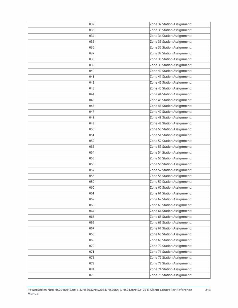
032 Zone 32 Station Assignment:
033 Zone 33 Station Assignment:
034 Zone 34 Station Assignment:
035 Zone 35 Station Assignment:
036 Zone 36 Station Assignment:
037 Zone 37 Station Assignment:
038 Zone 38 Station Assignment:
039 Zone 39 Station Assignment:
040 Zone 40 Station Assignment:
041 Zone 41 Station Assignment:
042 Zone 42 Station Assignment:
043 Zone 43 Station Assignment:
044 Zone 44 Station Assignment:
045 Zone 45 Station Assignment:
046 Zone 46 Station Assignment:
047 Zone 47 Station Assignment:
048 Zone 48 Station Assignment:
049 Zone 49 Station Assignment:
050 Zone 50 Station Assignment:
051 Zone 51 Station Assignment:
052 Zone 52 Station Assignment:
053 Zone 53 Station Assignment:
054 Zone 54 Station Assignment:
055 Zone 55 Station Assignment:
056 Zone 56 Station Assignment:
057 Zone 57 Station Assignment:
058 Zone 58 Station Assignment:
059 Zone 59 Station Assignment:
060 Zone 60 Station Assignment:
061 Zone 61 Station Assignment:
062 Zone 62 Station Assignment:
063 Zone 63 Station Assignment:
064 Zone 64 Station Assignment:
065 Zone 65 Station Assignment:
066 Zone 66 Station Assignment:
067 Zone 67 Station Assignment:
068 Zone 68 Station Assignment:
069 Zone 69 Station Assignment:
070 Zone 70 Station Assignment:
071 Zone 71 Station Assignment:
072 Zone 72 Station Assignment:
073 Zone 73 Station Assignment:
074 Zone 74 Station Assignment:
075 Zone 75 Station Assignment:
213PowerSeries Neo HS2016/HS2016-4/HS3032/HS2064/HS2064 E/HS2128/HS2129 E Alarm Controller ReferenceManual
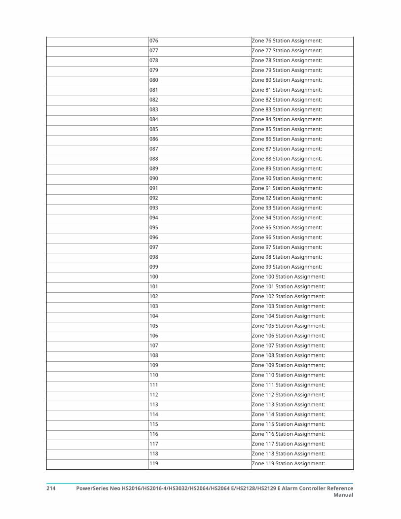
076 Zone 76 Station Assignment:
077 Zone 77 Station Assignment:
078 Zone 78 Station Assignment:
079 Zone 79 Station Assignment:
080 Zone 80 Station Assignment:
081 Zone 81 Station Assignment:
082 Zone 82 Station Assignment:
083 Zone 83 Station Assignment:
084 Zone 84 Station Assignment:
085 Zone 85 Station Assignment:
086 Zone 86 Station Assignment:
087 Zone 87 Station Assignment:
088 Zone 88 Station Assignment:
089 Zone 89 Station Assignment:
090 Zone 90 Station Assignment:
091 Zone 91 Station Assignment:
092 Zone 92 Station Assignment:
093 Zone 93 Station Assignment:
094 Zone 94 Station Assignment:
095 Zone 95 Station Assignment:
096 Zone 96 Station Assignment:
097 Zone 97 Station Assignment:
098 Zone 98 Station Assignment:
099 Zone 99 Station Assignment:
100 Zone 100 Station Assignment:
101 Zone 101 Station Assignment:
102 Zone 102 Station Assignment:
103 Zone 103 Station Assignment:
104 Zone 104 Station Assignment:
105 Zone 105 Station Assignment:
106 Zone 106 Station Assignment:
107 Zone 107 Station Assignment:
108 Zone 108 Station Assignment:
109 Zone 109 Station Assignment:
110 Zone 110 Station Assignment:
111 Zone 111 Station Assignment:
112 Zone 112 Station Assignment:
113 Zone 113 Station Assignment:
114 Zone 114 Station Assignment:
115 Zone 115 Station Assignment:
116 Zone 116 Station Assignment:
117 Zone 117 Station Assignment:
118 Zone 118 Station Assignment:
119 Zone 119 Station Assignment:
PowerSeries Neo HS2016/HS2016-4/HS3032/HS2064/HS2064 E/HS2128/HS2129 E Alarm Controller ReferenceManual
214

120 Zone 120 Station Assignment:
121 Zone 121 Station Assignment:
122 Zone 122 Station Assignment:
123 Zone 123 Station Assignment:
124 Zone 124 Station Assignment:
125 Zone 125 Station Assignment:
126 Zone 126 Station Assignment:
127 Zone 127 Station Assignment:
128 Zone 128 Station Assignment:
[802][600]600 2-Way Audio Trigger Option 1 1 - ☐ Tampers
2 - ☐Future Use3 - ☐ [A] Key Alarm4 - ☐ [P] Key Alarm5 - ☐ Duress Alarm6 - ☐ Opening After Alarm7 - ☐ Future Use8 - ☐ Zone Supervision Alarm
603 2-Way Audio Control Option 1 1 - ☐ Future Use2 - ☐ Listen to all zones /Listen to zones in alarm3 - ☐ Future Use4 - ☐ Siren Active During 2-Way Audio5 - ☐ Hang-Up Auto Detection6 - ☐ User Call-In7 - ☐ For Future Use8 - ☑ 2-Way Audio Initiated byCS
605 Record Options 1 - ☐ Audio Capture Enable2 - ☐ Erase on FTC3 - ☐ Future Use4 - ☐ Future Use5 - ☐ Future Use6 - ☐ Future Use7 - ☐ Future Use8 - ☐ Future Use
606 Audio Station Record ControlOption 1
1 - ☐ Audio Station 1 Record2 - ☐ Audio Station 2 Record3 - ☐ Audio Station 3 Record4 - ☐ Audio Station 4 Record5 - ☐ Future Use6 - ☐ Future Use7 - ☐ Future Use8 - ☐ Future Use
610 Call Back / Recovery Window Duration: 2 digit entryDefault: 05 minutes
215PowerSeries Neo HS2016/HS2016-4/HS3032/HS2064/HS2064 E/HS2128/HS2129 E Alarm Controller ReferenceManual

611 Call Back Acknowledge code:6-digit entryDefault: 999999
612 Answering Machine Bypass:2-digit entryDefault: 00
613 Double Call Timer:2-digit entryDefault: 30
614 Number of Rings to Answer:2-digit entryDefault: 00
615 Audio Duration:2-digit entryDefault: 90
616 Record Time:3-digit entryDefault: 105
617 Erase Time:2-digit entryDefault: 15 minutes
620 Audio Station Tamper Option1:
1 - ☐ Audio Station 1 Tamper2 - ☐ Audio Station 2 Tamper3 - ☐ Audio Station 3 Tamper4 - ☐ Audio Station 4 Tamper5 - ☐ Future Use6 - ☐ Future Use7 - ☐ Future Use8 - ☐ Future Use
999 Reset Module Programmingto Factory Defaults
999 installer code 999
Wireless Programming[804] Wireless ProgrammingSee the HSM2HOSTx installation manual and wireless device installation sheets for detailed information.
000 – WLS Device Enrollment Zones: (Selection) Zone #:
Zone Definition:
(2-digit decimal) Partition Assignment:
(14 x 2) Zone Label:
This section is an overview ofwireless device programming.See the associated deviceinstallation sheets and theHSM2HOST/RFK keypadinstallation instructions fordetailed worksheets
WLS Keys (Selection) WLS Key #:
(2-digit decimal) Partition Assignment:
(Selection) Select User:
WLS Key Label:
Sirens (Selection) Siren #:
PowerSeries Neo HS2016/HS2016-4/HS3032/HS2064/HS2064 E/HS2128/HS2129 E Alarm Controller ReferenceManual
216

(2-digit decimal) Partition Assignment:
(14 x 1) Siren Label:
Keypads (2-digit decimal) Keypad #:
(2-digit decimal) Partition Assignment:
Keypad Label:
Repeaters (Selection) Repeater #:
Repeater Label:
001- 128 Configure Wireless Zones 1 to 128
551-556 Configure Wireless Sirens 1-16
601-632 Configure Wireless Keys 1-32
701-716 Configure Wireless Keypads
801-810 Wireless Options
841 Visual Verification Programming
901-905 Delete Wireless Devices
921-925 Replace Wireless Devices
990 Show All Devices
999 Reset Devices to Factory Default
Alternate Communicators[850] Cellular Signal Strength(Description on [850] Cellular Signal Strength)[851] Alternate Communicator ProgrammingRefer to the installation instructions provided with the alternate communicator for details.
Keypad Programming[860] Display Keypad Slot Number(Description on [860] Display Keypad Slot Number)[861]-[876] Keypad ProgrammingRefer to the installation instructions provided with the keypad for details.
000 – Keypad Partition Mask 00 – Global
01 – ☑ Partition 1 05 – ☐ Partition 5
02 – ☐ Partition 2 06 – ☐ Partition 6
03 – ☐ Partition 3 07 – ☐ Partition 7
04 – ☐ Partition 4 08 – ☐ Partition 8
001 – Function Key 1 (Default: 0300):
002 – Function Key 2 (Default: 0400):
003 – Function Key 3 (Default: 06):
004 – Function Key 4 (Default: 22):
005 – Function Key 5 (Default: 1600):
Function Key ProgrammingOptions:
Function Key Programming Options:
217PowerSeries Neo HS2016/HS2016-4/HS3032/HS2064/HS2064 E/HS2128/HS2129 E Alarm Controller ReferenceManual

00 - Null Key02 - Instant Stay Arm03 - Stay Arm04 - Away Arm05 - [*][9]No Entry Arm06 - Chime On/Off07 - System Test09 - Night Arm12 - Global Stay Arm13 - Global Away Arm14 - Global Disarming16 - Quick Exit
17 - Arm Interior21 - Command Output 122 - Command Output 223 - Command Output 324 - Command Output 429 - Bypass Group Recall31 - Local PGM Active32 - Bypass Mode33 - Bypass Recall34 - User Programming35 - User Functions
37 - Time/Date Programming39 - Trouble Display40 - Alarm Memory61 - Partition Select 162 - Partition Select 263 - Partition Select 364 - Partition Select 465 - Partition Select 566 - Partition Select 667 - Partition Select 768 - Partition Select 8
011 – Keypad I/O (Zone number or output number; 3-digit decimal; Default: 000):
012 – Local PGM Output Timer Pulse Time Minutes (Default: 00 minutes)
Pulse Time Seconds (Default: 05 seconds)
1 – ☑ [F] Key Enabled021 – Keypad Option 1For systems compliant withEN50131-1 and EN50131-3Section [021]: options 1 and 2must be OFF.2-digit decimal
2 – ☑ ☑ [M] Key Enabled
3 – ☑ ☑ [P] Key Enabled
4 – ☑ Display Code or X’s
022 – Keypad Option 2 1 – ☑ Local Clock Display
2 – ☐ Local Clock 24-Hour
3 – ☑ Auto Alarm Scroll
5 – ☐ Power LED
6 – ☑ Power LED AC Present
7 – ☑ Alarms Displayed While Armed
8 – ☑ Auto Scroll Open Zones
023 – Keypad Option 3 1 – ☐ Armed LED Power Save
2 – ☑ Keypad Status Shows Arm Mode
3 – ☐ 5th Terminal is PGM Output/Zone Input
4 – ☐ Prox Tag Arm/Disarm
7 – ☐ Local Display of Temperature
8 – ☐ Low Temperature Warning
030 – LCD Message: (/TycoIS FOCUS/)
031 – Downloaded LCD Message Duration (3-digit decimal; 000-255; Default: 000):
041 – Indoor Temperature Zone Entry (3-digit decimal; 000-128; Default: 000):
042 – Outdoor Temperature Zone Entry (3-digit decimal; 000-128; Default: 000):
101-228 – Door Chime Sound: 00 – ☐ Disabled
01 – ☑ 6 Beeps
02 – ☐ Bing Bong
03 – ☐ Ding Dong
PowerSeries Neo HS2016/HS2016-4/HS3032/HS2064/HS2064 E/HS2128/HS2129 E Alarm Controller ReferenceManual
218

04 – ☐ Alarm Tone
05 – ☐ Zone Name
Door Chime Zone Assignment:1 ____ 13 ____ 25 ____ 37 ____ 49 ____ 61 ____ 73 ____ 85 ____ 97 ____ 109 ____ 121 ____2 ____ 14 ____ 26 ____ 38 ____ 50 ____ 62 ____ 74 ____ 86 ____ 98 ____ 110 ____ 122 ____3 ____ 15 ____ 27 ____ 39 ____ 51 ____ 63 ____ 75 ____ 87 ____ 99 ____ 111 ____ 123 ____4 ____ 16 ____ 28 ____ 40 ____ 52 ____ 64 ____ 76 ____ 88 ____ 100 ____ 112 ____ 124 ____5 ____ 17 ____ 29 ____ 41 ____ 53 ____ 65 ____ 77 ____ 89 ____ 101 ____ 113 ____ 125 ____6 ____ 18 ____ 30 ____ 42 ____ 54 ____ 66 ____ 78 ____ 90 ____ 102 ____ 114 ____ 126 ____7 ____ 19 ____ 31 ____ 43 ____ 55 ____ 67 ____ 79 ____ 91 ____ 103 ____ 115 ____ 127 ____8 ____ 20 ____ 32 ____ 44 ____ 56 ____ 68 ____ 80 ____ 92 ____ 104 ____ 116 ____ 128 ____9 ____ 21 ____ 33 ____ 45 ____ 57 ____ 69 ____ 81 ____ 93 ____ 105 ____ 117 ____10 ___ 22 ____ 34 ____ 46 ____ 58 ____ 70 ____ 82 ____ 94 ____ 106 ____ 118 ____11 ___ 23 ____ 35 ____ 47 ____ 59 ____ 71 ____ 83 ____ 95 ____ 107 ____ 119 ____12 ___ 24 ____ 36 ____ 48 ____ 60 ____ 72 ____ 84 ____ 96 ____ 108 ____ 120 ____
Template Programming[899] Template Programming
5 Digit Template Code:
Central Station Phone Number:
Description on TemplateProgramming
Central Station Account Code:
Partition Account Code:
DLS Access Code:
Partition 1 Entry Delay 1:
Partition 1 Exit Delay:
Installer Code:
System information☐ [F] FIRE☐ [M] MEDICAL☐ [P] PANIC
The Exit Delay Time is _______ seconds.
The Entry Delay Time is _______ seconds.
Module Programming[902] Add/Remove Modules
Description on [902] Add/Remove Modules
000 – Auto Enroll Modules
001 – Enroll Modules
002 – Slot Assignment
219PowerSeries Neo HS2016/HS2016-4/HS3032/HS2064/HS2064 E/HS2128/HS2129 E Alarm Controller ReferenceManual

003 – Edit Module SlotAssignment101 – Delete Keypads
102 – Delete HSM2108 8 ZoneModule103 – Delete HSM2208 8 OutputModule or High Current O/P106 – Delete HSM2Host
108 – Delete HSM2955
109 – Delete HSM2300 PowerSupply 1A110 – Delete HSM2204 4 HighCurrent Output
[903] Confirm Modules000 – View All Modules
Description on [903] ConfirmModule
001 – View Keypads*
002 – View HSM2108 8 ZoneModule*
*LED and ICON keypads 003 – View HSM2208 8 OutputModule O/P*006 – View HSM2Host*
009 – View HSM2300 PowerSupply 1A*010 – View HSM2204 4 HighCurrent Output*
Description on [903] ConfirmModule
101 – Confirm Keypads
102 – ConfirmHSM2108 8 ZoneModule103 – Confirm HSM2208 8Output Module or High CurrentO/P106 – Confirm HSM2Host
108 – Confirm HSM2955
109 – Confirm HSM2300 PowerSupply 1A110 – Confirm HSM2204 4 HighCurrent Output
PowerSeries Neo HS2016/HS2016-4/HS3032/HS2064/HS2064 E/HS2128/HS2129 E Alarm Controller ReferenceManual
220
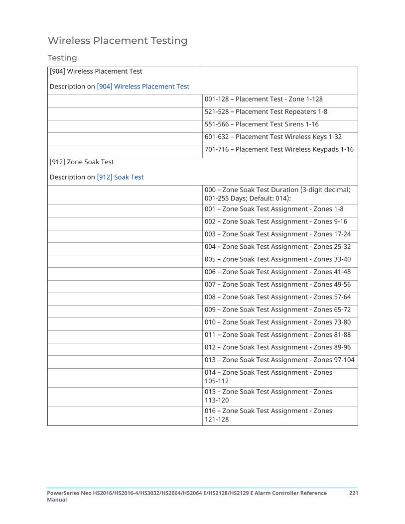
Wireless Placement Testing
Testing[904] Wireless Placement Test
Description on [904] Wireless Placement Test
001-128 – Placement Test - Zone 1-128
521-528 – Placement Test Repeaters 1-8
551-566 – Placement Test Sirens 1-16
601-632 – Placement Test Wireless Keys 1-32
701-716 – Placement Test Wireless Keypads 1-16
[912] Zone Soak Test
Description on [912] Soak Test
000 – Zone Soak Test Duration (3-digit decimal;001-255 Days; Default: 014):001 – Zone Soak Test Assignment - Zones 1-8
002 – Zone Soak Test Assignment - Zones 9-16
003 – Zone Soak Test Assignment - Zones 17-24
004 – Zone Soak Test Assignment - Zones 25-32
005 – Zone Soak Test Assignment - Zones 33-40
006 – Zone Soak Test Assignment - Zones 41-48
007 – Zone Soak Test Assignment - Zones 49-56
008 – Zone Soak Test Assignment - Zones 57-64
009 – Zone Soak Test Assignment - Zones 65-72
010 – Zone Soak Test Assignment - Zones 73-80
011 – Zone Soak Test Assignment - Zones 81-88
012 – Zone Soak Test Assignment - Zones 89-96
013 – Zone Soak Test Assignment - Zones 97-104
014 – Zone Soak Test Assignment - Zones105-112015 – Zone Soak Test Assignment - Zones113-120016 – Zone Soak Test Assignment - Zones121-128
221PowerSeries Neo HS2016/HS2016-4/HS3032/HS2064/HS2064 E/HS2128/HS2129 E Alarm Controller ReferenceManual

Battery Settings[982] Battery SettingsDescription on [982] Battery Settings
000 – Panel Battery Settings 01 – ☐ Panel High Charge Current
010 – HSM2204 High CurrentOutput Battery
01 – ☐ HSM2204 1 High ChargeCurrent
02 – o HSM2204 2 High ChargeCurrent
03 – ☐ HSM2204 3 High ChargeCurrent
04 – ☐ HSM2204 4 High ChargeCurrent
020 – HSM2300 1A PowerSupply Battery
01 – ☐ HSM2300 1 High ChargeCurrent
02 – ☐ HSM2300 2 High ChargeCurrent
03 – ☐ HSM2300 3 High ChargeCurrent
04 – ☐ HSM2300 4 High ChargeCurrent
Restoring Factory Defaults[989] Default Master Code
[990] Installer Lockout Enable/Disable
[991] Default Keypads
999 – Default All Keypads
901-916 – Default Keypad 1-16
[993] Default Alt Comm
[996] Default HSM2HOST Wireless Receiver
[988] Default HSM2955
[999] Default System(Descriptions on [989] Default Master Code)
Programming Worksheets
Troubleshooting
Testing• Power up system• Program options as required (see )• Manually trip then restore zones
PowerSeries Neo HS2016/HS2016-4/HS3032/HS2064/HS2064 E/HS2128/HS2129 E Alarm Controller ReferenceManual
222

• Verify correct reporting codes are sent to the central station
TroubleshootingLCD programmable-message keypad:
• Press [*][2] followed by access code if required to view a trouble condition• The trouble light flashes and the LCD displays the first trouble condition• Use the arrow keys to scroll through all trouble conditions present on the system
Note: When additional information is available for a specific trouble condition, a [*] isdisplayed. Press the [*] key to view the additional information.
[*][2] Trouble summaryThe list below describes the trouble indications displayed on keypads.
Trouble Detailed trouble
01 – ServiceRequired
01 – Bell circuit02 – RF jam detected03 – Loss of clock04 – Output 1 fault05 – Warm start
06 – USB Wi-Fi Connected07 – Power Unit Fail (System)08 – Power Unit Failure (HSM3204CX Corbus Repeater)09 – Power Unit Failure (HSM3350 3 A Power Supply)10 – Overcurrent
02 – ModuleLow Battery
01 – Panel low battery02 – Panel no battery04 – HSM2204 1-4 low battery05 – HSM2204 1-4 no battery07 – HSM2300 1-4 low battery08 – HSM2300 1-4 no battery
10 – HSM3204CX low battery11 – HSM3204CX no battery13 – HSM3350 low battery 114 – HSM3350 low battery 215 – HSM3350 no battery 116 – HSM3350 no battery 2
03 – BusVoltage
01 – HSM2HOSTx voltage02 – Keypad 1-32 voltage04 – HSM2108 1-15 voltage05 – HSM2300 1-4 voltage06 – HSM2204 1-4 voltage07 – Panel Corbus Output Fault (system)
08 – HSM2208 1-4 voltage09 – HSM2955 1-4 voltage10 – HSM3408 voltage11 – HSM3204CX bus low voltage12 – HSM3204CX bus fault13 – HSM3350 bus low voltage
04 – ACTroubles
01 – Zone 1-248 AC02 - Keypad AC Trouble03 – Siren 1-16 AC04 – Repeater 1-8 AC05 – HSM2300 1-4 AC
06 – HSM2204 1-4 AC07 – Alarm controller AC08 – HSM3204CX AC09 – HSM3350 AC
05 – DeviceFaults
01 – Zone 001 - 24803 – Siren 1-1604 – Repeater 1-806 – Device mask
08 – Heat trouble09 – CO trouble10 – Freeze trouble11– Probe disconn.12– Fire trouble
06 – DeviceLow Battery
01 – Zone 1-24802 – Keypad 1-3203 – Siren 1-16
04 – Repeater 1-805 – User 1-32
07 – DeviceTampers
01 – Zone 1-24803 – Siren 1-16
04 – Repeater 1-805 – Audio Station 01 - 04
08 – RFDelinquency
01 – Zone 1-24802 – Keypad 1-32
03 – Siren 1-1604 – Repeater 1-8
223PowerSeries Neo HS2016/HS2016-4/HS3032/HS2064/HS2064 E/HS2128/HS2129 E Alarm Controller ReferenceManual

Trouble Detailed trouble
09 – ModuleSupervisory
01 – HSM2HOSTx02 – Keypad 1-3204 – HSM2108 1-3005 – HSM2300 1-406 – HSM2204
08 – HSM2208 1-409 – HSM295511 – HSM340812 – HSM3204CX13 – HSM3350
10 – ModuleTamper
01 – HSM2HOSTx02 – Keypad 1-3204 – HSM2108 1-3005 – HSM2300 1-406 – HSM2204
08 – HSM2208 1-409 – HSM295511 – HSM3408 1-3012 – HSM3204CX13 – HSM3350
11 –Communications
01 – TLM02 – FTC Receiver 1-404 – Alt. comm cellular05 – Alt. comm Ethernet
06 – Receiver 1-4 absent07 – Receiver 1-4 supervision09 – Alt. comm fault10 – Alt. comm FTCtrouble
12 – NotNetworked
01 – Zone 1-24802 – Keypad 1-3203 – Siren 1-16
04 – Repeater 1-805 – User 1-32
13 – AUXTrouble
05 – HSM230006 – HSM220407 – System area
10 – HSM340811 – HSM3204CX12 – HSM3350 AUX 1 trouble13 – HSM3350 AUX 2 trouble
14 – LimitExceededTrouble
01 – Interactive Zone02 – Interactive Partition
Trouble [1] Service Required Press [01] to determine specific troubleTrouble Troubleshooting
[01] Bell CircuitBell+, Bell-.open circuit.
Disconnect Bell-/+ leads and measure resistance:Open circuit indicates break in wiring or defective siren/bell.Jumper Bell+/- with 1K resistor (Brown, Black, Red):
[02] RF Jam DetectedWireless receiver - excessive noisedetected.
Check event buffer to determine specific trouble.If buffer logs RF jam, check for RF interference.Disable RF Jam: section [804] sub-section [801].
[03] Loss of clockThe alarm controller internal clock is notset
To program the time and date: Enter [*][6][Master Code] then press [01].Enter the time and date (24-hour clock) using the following format: HH:MM MM/DD/YYe.g.,. For 6:00 pm, June 29, 2019:Enter: [18] [00] [06] [29] [19]
[04] Output 1 FaultHSM2204 output #1 open circuit.
If output #1 is unused: ensure terminals O1, AUX are jumpered with 1K resistor(brown, black, red).If output #1 is used: disconnect wire leads from O1, AUX terminals, measureresistance of leads: Open circuit indicates a break in wiring.
[05] Warm StartControl panel has recovered from asoftware lockup
This trouble automatically restores after two minutes or when acknowledgevia the [*] 2 menu. Contact Tech Support if this trouble persists or re-occursperiodically.
[06] USB Wi-Fi ConnectedHSM3WIFI USB to Wi-Fi Adapter isplugged into the panel
The trouble automatically clears once the HSM3WIFI adapter is unplugged fromthe panel. This trouble serves as a warning as to not to forget to unplug theadapter when configuration via Wi-Fi is completed.
[07] Power Unit Fail (System)A fault with the internal power supply hasbeen detected on the panel.
Ensure the combined output power of the panel is not exceeding 2A. Powercycle the panel and if the trouble persists it may indicate a permanent hardwarefailure.
PowerSeries Neo HS2016/HS2016-4/HS3032/HS2064/HS2064 E/HS2128/HS2129 E Alarm Controller ReferenceManual
224

Trouble [1] Service Required Press [01] to determine specific trouble[08] Power Unit Failure (HSM3204CX)A fault with the internal power supply hasbeen detected on the corbus repeater.
Ensure the combined output power of the corbus repeater module is notexceeding 2A. Power cycle the module and if the trouble persists it may indicatea permanent hardware failure.
[09] Power Unit Failure (HSM3350)A fault with the internal power supply hasbeen detected on the 3A power supply.
Ensure the combined output power of the 3A power supply module is notexceeding 3A. Power cycle the module and if the trouble persists it may indicatea permanent hardware failure.
[10] OvercurrentThe combined output power on the panelhas exceeded 2A for a period of more than5 minutes.
Reduce the load on the panel by re-powering modules or detectors with aseparate power supply module.
Trouble [2] Module Battery Trouble Press [02] to determine specific troubleTrouble Troubleshooting[01] Panel Low BatteryThe panel detects that the battery isbelow the low battery threshold (less than11.5VDC).
Note: This trouble condition willnot clear until the battery voltage is12.5VDC min., under load. If batteryis new allow 1 hour to charge.
Verify voltage measured across DC input terminals is 16-18 VAC. ReplaceHSM65W power supply adapter if required.Connect battery, remove AC power.Verify measured voltage across Aux terminals is 12.5VDC min.Replace battery if it is no longer able to hold a charge due to age.
[02] Panel No BatteryThe panel detects that no battery ispresent or that the battery is shorted.
Verify battery is connected.Ensure battery leads are connected with the right polarity.Connect battery, remove AC power.Verify measured voltage across Aux terminals is 12.5VDC min
[04] 4 High Current output 1-4 Low Battery(HSM2204)HSM2204 battery less than 11.5VDC.
Note: This trouble condition willnot clear until the battery voltageis 12.5VDC min. under load. Chargebattery. It may be low due to a longperiod without AC.
Verify voltage measured across DC input terminals is 16-18 VDC. ReplaceHSM65W power supply adapter if required.Connect battery, remove AC power.Verify measured voltage across Aux terminals is 12.5VDC min.Replace battery if it is no longer able to hold a charge due to age.
[05] 4 High Current output 1-4 No Battery(HSM2204)Enter 05 to view which HSM2204 does nothave a battery connected.
Verify battery is connected.Ensure battery leads are connected with the right polarity.Connect battery, remove AC power.Verify measured voltage across Aux terminals is 12.5VDC min
[07] Power Supply 1-4 Low Battery(HSM2300)Enter 07 to view which HSM2300 has abattery voltage less than 11.5V.
Verify voltage measured across DC input terminals is 16-18 VAC. ReplaceHSM65W power supply adapter if required.Connect battery, remove AC power.Verify measured voltage across Aux terminals is 12.5VDC min.Replace battery if it is no longer able to hold a charge due to age.
[08] Power Supply 1-4 No Battery(HSM2300)Enter 08 to view which HSM2300 does nothave a battery connected.
Verify battery is connected.Ensure battery leads are connected with the right polarity.Connect battery, remove AC power.Verify measured voltage across Aux terminals is 12.5VDC min
[10] HSM3204CX low batteryEnter 10 to view which HSM3204X has abattery voltage less than 11.5V
Verify voltage measured across DC input terminals is 16-18 VAC. ReplaceHSM65W power supply adapter if required.Connect battery, remove AC power.Verify measured voltage across Aux terminals is 12.5VDC min.Replace battery if it is no longer able to hold a charge due to age.
225PowerSeries Neo HS2016/HS2016-4/HS3032/HS2064/HS2064 E/HS2128/HS2129 E Alarm Controller ReferenceManual

Trouble [2] Module Battery Trouble Press [02] to determine specific trouble
[11] HSM3204CX no batteryEnter 11 to view which HSM3204CX doesnot have a battery connected.
Verify voltage measured across DC input terminals is 16-18 VAC. ReplaceHSM65W power supply adapter if required.Connect battery, remove AC power.Verify measured voltage across Aux terminals is 12.5VDC min.Replace battery if it is no longer able to hold a charge due to age.
[13] HSM3350 low battery 1Enter 13 to view which HSM3350 has abattery voltage less than 11.5V.
Verify voltage measured across DC input terminals is 16-18 VAC. ReplaceHSM65W power supply adapter if required.Connect battery, remove AC power.Verify measured voltage across Aux terminals is 12.5VDC min.Replace battery if it is no longer able to hold a charge due to age.
[14] HSM3350 low battery 2Enter 14 to view which HSM3350 has abattery voltage less than 11.5V.
Verify voltage measured across DC input terminals is 16-18 VAC. ReplaceHSM65W power supply adapter if required.Connect battery, remove AC power.Verify measured voltage across Aux terminals is 12.5VDC min.Replace battery if it is no longer able to hold a charge due to age.
[15 ] HSM3350 no battery 1Enter 15 to view which HSM3350 does nothave a battery connected.
Verify battery is connected.Ensure battery leads are connected with the right polarity.Connect battery, remove AC power.Verify measured voltage across Aux terminals is 12.5VDC min
[16] HSM3350 no battery 2Enter 16 to view which HSM3350 does nothave a battery connected
Verify battery is connected.Ensure battery leads are connected with the right polarity.Connect battery, remove AC power.Verify measured voltage across Aux terminals is 12.5VDC min
PowerSeries Neo HS2016/HS2016-4/HS3032/HS2064/HS2064 E/HS2128/HS2129 E Alarm Controller ReferenceManual
226

Trouble [3] Bus Voltage Trouble Press [03] to determine specific troubleTrouble Troubleshooting[01] HSM2HOST Bus Low VoltageThe 2-way wireless integration modulehas detected a voltage less than 6.3V onits aux input.[02] Keypad 1-32 Bus Low VoltageEnter 02 to view hardwired keypads witha bus voltage of less than 6.9V for modelsthat include a wireless transceiver, 7.7V forthe models that do not.[04] HSM2108 Bus Low VoltageEnter 04 to view zone expanders with abus voltage of less than 5.9V.[05] HSM2300 Bus Low VoltageEnter 05 to view power supplies with a busvoltage of less than 6.9V.[06] HSM2204 Bus Low VoltageEnter 06 to view high current outputmodules that have detected a bus voltageof less than 6.9V.[07] Panel Corbus Fault The panel hasdetected that its corbus output voltage isless than 9.0V or higher than 15V[08] HSM2208 Bus Low VoltageThe low current output module hasdetected a voltage less than 5.9V on itsaux input.[09] HSM2955 Bus Low VoltageThe audio module has detected a voltageless than 9.65V on its aux input.[10] HSM3408 voltageThe audio module has detected a voltageless than 6.4V on its aux input.[11] HSM3204CX bus low voltageThe audio module has detected a voltageless than 6.0V on its aux input.[12] HSM3204CX bus faultEnter 12 to view corbus repeaters whichhave detected the voltage on the corbusoutput is less than 9.0V[13] HSM3350 bus low voltageEnter 12 to view corbus repeaters whichhave detected the voltage on the corbusoutput is less than 6.0V
Ensure voltage at module is higher than the documented limits.Ensure wire run is not too long.Check voltage of panel battery.Trouble should clear when AC is re-applied and the battery has had time tocharge.Disconnect AC and allow the panel to run on battery power. Ensure voltage atmodule is higher than the documented limits.Ensure that the corbus is not being overloaded or that there is no shortanywhere on the wire run.
227PowerSeries Neo HS2016/HS2016-4/HS3032/HS2064/HS2064 E/HS2128/HS2129 E Alarm Controller ReferenceManual

Trouble [4] AC Failure Press [04] to determine specific troubleTrouble Troubleshooting[01] Zone 1-248 AC[03] Siren 1-16 AC[04] Repeater 1-8 AC[05] HSM2300 1-4 AC[06] HSM2204 1-4 AC[07] Alarm Controller[08] HSM3204CX AC[09] HSM3350 ACAn AC trouble has been detected on adevice or module.
Verify voltage measured across DC input terminals is 16-20VDC. ReplaceHSM65W power adapter if required.For the HSM2204 or HSM2300 modules, ensure a 40VA 16.5VAC transformeris being used. Terminal voltage should be 16-17VAC. Replace transformer ifrequired.
Trouble [05] Device Faults Press [05] to determine specific troubleTrouble TroubleshootingFire Trouble:When a Fire Trouble is generated at the[05] Device faults ie Device Faults > FireTrouble
Ensure that, if the PGM-2 is configured as 2-wire smoke detector and not used,5.6K EOL resistor is used.
[01] Zone 1-248 faultsWireless zones:Enter [01] to view zones in fault. Thistrouble is generated by a zone wirelesssupervisory trouble.
Ensure fire zones have a 5.6K resistor (green, blue, red) connected.Remove wire leads from Z and COM terminals and measure resistance of thewire leads:Check for a short on DEOL zones or an open condition on SEOL fire zones.Connect a 5.6K resistor across the Z and COM terminals. Verify the troublecondition clears.Placement test a wireless device and re-locate it if bad results are received.
Hardwired zones:This trouble is generated by a short onhardwired zones when DEOL or TEOL isused.[03] Siren 1-16 faultsThis trouble is caused by a wirelesssupervisory fault on a wireless siren.
Placement test the wireless siren and re-locate if needed.
[04] Repeater 1-8 faultsThis trouble is caused by a wirelesssupervisory fault on a wireless repeater,or by the repeater shutting down due to aloss of AC/DC power.
Placement test the wireless repeater and re-locate if needed.
[06] Device maskEnter [06] to view the zone label inmasking condition. A zone programmedas 24H Anti- Masking or a wireless devicehas detected a masking condition withone of its sensors.
Refer to the device manual to troubleshoot conditions that may cause maskingdetection for that devices sensors.
[08] Heat troubleEnter 10 to view the wireless zone which isdetecting low temperature.
Move the device to a location with room temperature and ensure the troubleclears. If not check the programming threshold for high temperature for thezone.
[09] CO troubleEnter 09 to view the zone of a CO wirelessdevice that is in low sensitivity trouble.
Refer to the CO devices manual for troubleshooting steps for low sensitivitytrouble.
PowerSeries Neo HS2016/HS2016-4/HS3032/HS2064/HS2064 E/HS2128/HS2129 E Alarm Controller ReferenceManual
228

Trouble [05] Device Faults Press [05] to determine specific trouble[10] Freeze troubleEnter 08 to view the wireless zone which isdetecting high temperature.
Move the device to a location with room temperature and ensure the troubleclears. If not check the programming threshold for low temperature for thezone.
[11] Probe disconnectEnter [11] to view the wireless zone whichhas detected a disconnected probe.
Refer to the temperature or flood detectors manual for troubleshooting stepsfor probe disconnected.
[12] Fire troubleEnter [012] to view which zones are in Firetrouble.
If fire zone is a wireless smoke, ensure it is not tampered, or in supervisorytrouble. Ensure the smoke chamber is cleared of dust. If a 2-wire smoke is used,ensure a 2.2K EOL resistor is used. If zone is a 4-wire smoke, ensure a 5.6K EOLresistor is used.
Trouble [6] Device Low Battery Press [06] to toggle through specific devices with low battery troubleTrouble Troubleshooting[01] Zones 1-248[02] Keypad 1-32[03] Siren 1-16[04] Repeater 1-8[05] User 1-32One or more wireless devices has a lowbattery.
Note: The event is not logged tothe event buffer until the wirelessdevice low battery delay timeexpires.
Programming section [377], Opt 002.
View which device is in low battery through the [*][2] menu.Replace the batteries in the device with same battery type.Verify that tamper and low battery condition is cleared and reported.Verify zone operation.
Trouble [7] Device Tamper Press [07] to determine specific troubleTrouble Troubleshooting[01] Zone 1-248 tampers[02] Keypad 1-32 tampers[03] Siren 1-16 tampers[04] Repeater 1-8 tampers[05] Audio Station 1-4 tampersAn open circuit is present on one ormore zones with DEOL or TEOL resistorsenabled.
Check that the tamper switch is securely attached to the wall.Remove the wire leads from I/O and COM and measure the resistance of thewire leads.Connect a 5.6K resistor (Green, Blue, Red) across the I/O and COM terminals.Verify the trouble condition clears.
A tamper condition is present on one ormore wireless devices.
Ensure device cover is secure.Ensure device is correctly mounted for wall tamper operation.Trip, then restore the tamper. If tamper condition persists, replace wirelessdevice.
Trouble [8] RF Delinquency Press [08] to determine specific troubleTrouble Troubleshooting[01] Zone 1-248 faults[02] Keypad 1-32 faults[03] Siren 1-16 faults[04] Repeater 1-8 faultsHSM2HOST has not received a supervisorysignal from a wireless device for 20minutes.
Open/close the device, press a key on the keypad or tamper/restore.Ensure the device is physically present.Check for device faults (e.g., low battery).Check the current signal strength and during the last 24 hours.Replace the battery.Replace the device.
229PowerSeries Neo HS2016/HS2016-4/HS3032/HS2064/HS2064 E/HS2128/HS2129 E Alarm Controller ReferenceManual

Trouble [9] Module Supervisory Press [09] to determine specific zones with a tamper troubleTrouble Troubleshooting[01] HSM2HOST[02] Keypad 1-30[04] HSM2108 1-15[05] HSM2300 1-4[06] HSM2204 1-4[08] HSM2208 1-4[09] HSM2955[10] HSM3408 1-30[11] HSM3204CX 1-16[12] HSM3350 1-4No supervisory response from enrolledmodule.
Ensure the module is physically connected to the corbus.Measure power across corbus Red and Blk directly on the module and ensure itis at 10.5V (min).Disconnect the module and using a short length of wire, connect it directly at thepanel. If the trouble then clears, it indicates a wiring problem. If the trouble doesnot clear, replace the module.If the module is no longer part of the system, delete it via section [902].
Trouble [10] Module Tamper Press [10] to determine specific troubleTrouble Troubleshooting[01] HSM2HOST[02] Keypad 1-32[04] HSM2108 1-30[05] HSM2300 1-4[06] HSM2204 1-4[08] HSM2208 1-4[09] HSM2955[10] Alt. comm.[11] HSM3408 1-30[12] HSM3204CX 1-16[13] HSM3350 1-4A tamper condition is present on one ormore modules.
Ensure the TAM terminal, if present on the modules is shorted to ground iftamper support is not used.Ensure module cabinet cover is securely closed and properly activating thetamper switch, if present.Ensure that the rubber tamper plunger is installed on the keypad back plasticsand that the keypad is securely closed and fastened to the wall.For the HSM2HOST, ensure the module is securely closed and correctly mountedfor wall tamper operation.Manually trip, then restore the tamper. If tamper condition persists, replace themodule.
Trouble [11] Communications Press [11] to determine specific troubleTrouble Troubleshooting
[01] Phone Line TroublePhone line voltage at TIP, RING on mainpanel less than 3VDC.
Measure the voltage across TIP and RING on the panel:No phone off-hook – 50VDC (approx).Any phone off-hook – 5VDC (approx).Wire incoming line directly to TIP and RING.If trouble clears, check wiring or the RJ-31 phone jack.If not using a phone line on the panel, disable it in section [015] option 7.
[02] FTC Receiver 1-4The system failed to communicate witha receiver using one of the enabledphone numbers. Enter [02] to view phonenumbers with failure to communicatetroubles.
If using PSTN communications, ensure the central station phone number isprogrammed correctly. If using IP or cellular, ensure alternate communicatorhas the correct central station IP and port numbers, as well as APN for cellular.
[03] Alternate Comm SIM LockSIM lock is enabled and the unit does nothave the correct SIM PIN.
Replace SIM card with one that does not have a SIM lock pin code programed.
PowerSeries Neo HS2016/HS2016-4/HS3032/HS2064/HS2064 E/HS2128/HS2129 E Alarm Controller ReferenceManual
230

Trouble [11] Communications Press [11] to determine specific trouble
[04] Alternate Comm CellularThe alternate communicator has detecteda radio or SIM failure, a cellular networktrouble, or insufficient signal strength.
Check the the event buffer for trouble details.For radio/SIM failure, ensure the cellular plug-in module is connected to thepanel properly and that the SIM card is correctly inserted in the right orientation.For Cellular Network trouble ensure the correct Cellular APN is programmed andthat the SIM card is activated.For insufficient signal strength, sure the antenna is properly connected andthe unit is mounted in a location which allows for a strong signal to the nearestcellular tower.
[05] Alternate Comm EthernetThe alternate communicator has detecteda network absent condition.
Check with the ISP to confirm Internet service is active in the area.Ensure the Ethernet cable is securely inserted into the RJ45 jack of thecommunicator and the hub/router/switch.Check the link light on the hub/router/switch is ON. If link light is OFF, start thehub/router/switch.If DHCP is used, ensure that the unit has an assigned IP address from the server.In Section [851] [992] verify a valid IP address is programmed. If not, contact thenetwork administrator.If problem persists, replace the Ethernet cable and RJ45 connector
[06] Receiver 1-4 TroubleAlternate communicator is failing toinitialize to the receiver.
Ensure that the Ethernet path has Internet connectivity.If using a static IP address, confirm that the gateway and subnet mask areentered correctly.If the network has a firewall, ensure the network has the programmed outgoingports open (default UDP port 3060 and port 3065).Ensure that all cellular receiver APNs have been programmed with the accesspoint name provided by the cellular provider.If Common Mode is used, and only one path is initiliazed while the other path isnot successful, generate a manual test transmission over both paths or powercycle the communicator to recover the "Receiver Not Available" trouble.
[07] Receiver 1-4 SupervisionThe alarm system loses communicationwith an Ethernet or cellular receiver on thesystem.
This trouble is indicated when supervision is enabled and the unit is not able tosuccessfully communicate with the receiver.If this trouble persists, contact the central station.
[09] Alternate Comm FaultThe alternate communicator has notresponded to any poll commands. AltComm Fault is displayed in [*][2] and theevent buffer.
Check section [382] toggle option [5] is ON if using an Alarm.com alternatecommunicator. If not, it should be OFF.Ensure the PC-LINK cable between the panel and Alarm.com communicator isconnected properly (not reversed) and is securely in place.
[10] Alternate Comm FTC FaultThe unit has exhausted all communications attempts to all programmedreceivers for events generated by the communicator.Restart the system and if trouble persists, contact the dealer.
Trouble [12] Not Networked Press [12] to toggle through troublesTrouble Troubleshooting[01] Zones 1-248[02] Keypad 1-32[03] Siren 1-16[04] Repeater 1-8[05] User 1-32A device is out of sync with the wirelessnetwork or was not synchronized with thenetwork after enrollment.
Ensure the device is physically present.Check the current signal strength and during the last 24 hours.Replace the battery or press the tamper switch.Enroll the device again.If wireless devices were recently enrolled, or the HSM2HOST was power cycled,wait up to 16 minutes for the device to synchronize to the network.
231PowerSeries Neo HS2016/HS2016-4/HS3032/HS2064/HS2064 E/HS2128/HS2129 E Alarm Controller ReferenceManual

Trouble [13] AUX Trouble Press [13] to toggle through troublesTrouble Troubleshooting[05] HSM2300[06] HSM2204[07] System area[10] HSM3408[11] HSM3204CX[12] HSM3350 AUX 1 trouble[13] HSM3350 AUX 2 troubleAn auxiliary power supply trouble ispresent.
Check for a short between Aux+ and Aux- or other system ground.Ensure the aux current draw has not exceeded the documented limits.Ensure voltage between AUX+ and AUx - is between 9VDC to 14VDC.
Trouble [14] Module Tamper Press [14] to determine specific troubleTrouble Troubleshooting
[01] Interactive Zone[02] Interactive Partition
Check the Alarm.com communicator firmware is compatible with PSP firmwareto support extended number of Zones and Partitions.Interactive Zone trouble is generated when the Alarm.com firmware does notsupport the configured number of zones in panel (>220 Zones) and InteractivePartition Trouble is generated when the Alarm.com firmware does not supportconfigured number of Partitions.Ensure to configure compatible number of zones and partitions while using withAlarm.com.
Note: Ensure you have the alarm controller type and version (for example, HSM3032 V1.1)and the list of modules connected to control panel, (for example, HSM2108, HSM2HOSTx andso on) available before contacting Customer Support. Version number can be accessed byentering [*][Installer Code][900] on any LCD keypad. This information is also located on asticker on the printed circuit board.
Reporting CodesThe following tables contain Contact ID and Automatic SIA format reporting codes. [308] EventReporting for event reporting codes.Contact IDEach of the digits indicate specific information about the signal. For example, if zone 1 is an entry/exit point, the event code contains [34]. The central station would receive the following:*BURG - ENTRY/EXIT - 1 where the “1” indicates which zone went into alarm.Contact ID and SIA Zone Alarm/Restore Event Codes for code definitions.SIA Format - Level 2 (Hard Coded)The SIA communication format used in this product follows the level 2 specifications of the SIADigital Communication Standard - October 1997. This format sends the account code along with itsdata transmission. The transmission appears similar to the following at the receiver:N ri1 BA 01N = New Eventri1 = Partition /Area IdentifierBA = Burglary Alarm01 = Zone 1A system event uses the Area Identifier ri00.
PowerSeries Neo HS2016/HS2016-4/HS3032/HS2064/HS2064 E/HS2128/HS2129 E Alarm Controller ReferenceManual
232

Contact ID and SIA Zone Alarm/Restore Event Codes
Section # Definition Dialer Direction*Automatic Contact IDCodes SIA Auto Rep Codes**
Zone Events[307] Zone Alarms A/R[307] Zone Restores A/R
Contact ID & SIA Zone Alarm/Restore EventCodes (as per SIA DCS: ‘Contact ID’ 01-1999):" fordetails.
[307] Zone tamper/restore MA/R E(3)83-ZZZ / R(3)83-ZZZ TA-ZZZ / TR-ZZZZ[307] Zone fault/restore MA/R E(3)8A-ZZZ / R(3)8A-ZZZ UT-ZZZZ / UJ-ZZZZTamper Events[308]-[101] Keypad 1 tamper/
restore alarmT/R E(3)83-601 / R(3)83-601 TA-0601 / TR-0601
[308]-[101] Keypad 2 tamper/restore alarm
T/R E(3)83-602 / R(3)83-602 TA-0602 / TR-0602
[308]-[101] Keypad 3 tamper/restore alarm
T/R E(3)83-603 / R(3)83-603 TA-0603 / TR-0603
[308]-[101] Keypad 4 tamper/restore alarm
T/R E(3)83-604 / R(3)83-604 TA-0604 / TR-0604
[308]-[101] Keypad 5 tamper/restore alarm
T/R E(3)83-605 / R(3)83-605 TA-0605 / TR-0605
[308]-[101] Keypad 6 tamper/restore alarm
T/R E(3)83-606 / R(3)83-606 TA-0606 / TR-0606
[308]-[101] Keypad 7 tamper/restore alarm
T/R E(3)83-607 / R(3)83-607 TA-0607 / TR-0607
[308]-[101] Keypad 8 tamper/restore alarm
T/R E(3)83-608 / R(3)83-608 TA-0608 / TR-0608
[308]-[101] Keypad 9 tamper/restore alarm
T/R E(3)83-609 / R(3)83-609 TA-0609 / TR-0609
[308]-[101] Keypad 10 tamper/restore alarm
T/R E(3)83-610 / R(3)83-610 TA-0610 / TR-0610
[308]-[101] Keypad 11 tamper/restore alarm
T/R E(3)83-611 / R(3)83-611 TA-0611 / TR-0611
[308]-[101] Keypad 12 tamper/restore alarm
T/R E(3)83-612 / R(3)83-612 TA-0612 / TR-0612
[308]-[101] Keypad 13 tamper/restore alarm
T/R E(3)83-613 / R(3)83-613 TA-0613 / TR-0613
[308]-[101] Keypad 14 tamper/restore alarm
T/R E(3)83-614 / R(3)83-614 TA-0614 / TR-0614
[308]-[101] Keypad 15 tamper/restore alarm
T/R E(3)83-615 / R(3)83-615 TA-0615 / TR-0615
[308]-[101] Keypad 16 tamper/restore alarm
T/R E(3)83-616 / R(3)83-616 TA-0616 / TR-0616
[308]-[101] Siren 1 tamper/restorealarm
T/R E (3)83-801 / R (3)83-801 TA-0801 / TR-0801
[308]-[101] Siren 2 tamper/restorealarm
T/R E(3)83-802 / R (3)83-802 TA-0802 / TR-0802
[308]-[101] Siren 3 tamper/restorealarm
T/R E(3)83-803 / R (3)83-803 TA-0803 / TR-0803
[308]-[101] Siren 4 tamper/restorealarm
T/R E (3)83-804 / R (3)83-804 TA-0804 / TR-0804
[308]-[101] Siren 5 tamper/restorealarm
T/R E(3)83-805 / R (3)83-805 TA-0805 / TR-0805
[308]-[101] Siren 6 tamper/restorealarm
T/R E(3)83-806 / R (3)83-806 TA-0806 / TR-0806
[308]-[101] Siren 7 tamper/restorealarm
T/R E(3)83-807 / R (3)83-807 TA-0807 / TR-0807
233PowerSeries Neo HS2016/HS2016-4/HS3032/HS2064/HS2064 E/HS2128/HS2129 E Alarm Controller ReferenceManual

Section # Definition Dialer Direction*Automatic Contact IDCodes SIA Auto Rep Codes**
[308]-[101] Siren 8 tamper/restorealarm
T/R E(3)83-808 / R (3)83-808 TA-0808 / TR-0808
[308]-[101] Siren 9 tamper/restorealarm
T/R E(3)83-809 / R (3)83-809 TA-0809 / TR-0809
[308]-[101] Siren 10 tamper/restorealarm
T/R E (3)83-810 / R (3)83-810 TA-0810 / TR-0810
[308]-[101] Siren 11 tamper/restorealarm
T/R E(3)83-811 / R (3)83-811 TA-0811 / TR-0811
[308]-[101] Siren 12 tamper/restorealarm
T/R E (3)83-812 / R (3)83-812 TA-0812 / TR-0812
[308]-[101] Siren 13 tamper/restorealarm
T/R E(3)83-813 / R (3)83-813 TA-0813 / TR-0813
[308]-[101] Siren 14 tamper/restorealarm
T/R E (3)83-814 / R (3)83-814 TA-0814 / TR-0814
[308]-[101] Siren 15 tamper/restorealarm
T/R E(3)83-815 / R (3)83-815 TA-0815 / TR-0815
[308]-[101] Siren 16 tamper/restorealarm
T/R E (3)83-816 / R (3)83-816 TA-0816 / TR-0816
[308]-[101] Repeater 1 tamper/restore alarm
T/R E(3)83-901 / R (3)83-901 TA-0901 / TR-0901
[308]-[101] Repeater 2 tamper/restore alarm
T/R E(3)83-902 / R (3)83-902 TA-0902 / TR-0902
[308]-[101] Repeater 3 tamper/restore alarm
T/R E(3)83-903 / R (3)83-903 TA-0903 / TR-0903
[308]-[101] Repeater 4 tamper/restore alarm
T/R E(3)83-904 / R (3)83-904 TA-0904 / TR-0904
[308]-[101] Repeater 5 tamper/restore alarm
T/R E(3)83-905 / R (3)83-905 TA-0905 / TR-0905
[308]-[101] Repeater 6 tamper/restore alarm
T/R E(3)83-906 / R (3)83-906 TA-0906 / TR-0906
[308]-[101] Repeater 7 tamper/restore alarm
T/R E(3)83-907 / R (3)83-907 TA-0907 / TR-0907
[308]-[101] Repeater 8 tamper/restore alarm
T/R E(3)83-908 / R (3)83-908 TA-0908 / TR-0908
[308]-[101] HSM2108: 8-ZoneExpander module #1tamper/restored
T/R E(3)41-101 / R(3)41-101 ES-0101 / EJ-0101
[308]-[101] HSM2108: 8-ZoneExpander module #2tamper/restored
T/R E(3)41-102 / R(3)41-102 ES-0102 / EJ-0102
[308]-[101] HSM2108: 8-ZoneExpander module #3tamper/restored
T/R E(3)41-103 / R(3)41-103 ES-0103 / EJ-0103
[308]-[101] HSM2108: 8-ZoneExpander module #4tamper/restored
T/R E(3)41-104 / R(3)41-104 ES-0104 / EJ-0104
[308]-[101] HSM2108: 8-ZoneExpander module #5tamper/restored
T/R E(3)41-105 / R(3)41-105 ES-0105 / EJ-0105
[308]-[101] HSM2108: 8-ZoneExpander module #6tamper/restored
T/R E(3)41-106 / R(3)41-106 ES-0106 / EJ-0106
[308]-[101] HSM2108: 8-ZoneExpander module #7tamper/restored
T/R E(3)41-107 / R(3)41-107 ES-0107 / EJ-0107
PowerSeries Neo HS2016/HS2016-4/HS3032/HS2064/HS2064 E/HS2128/HS2129 E Alarm Controller ReferenceManual
234

Section # Definition Dialer Direction*Automatic Contact IDCodes SIA Auto Rep Codes**
[308]-[101] HSM2108: 8-ZoneExpander module #8tamper/restored
T/R E(3)41-108 / R(3)41-108 ES-0108 / EJ-0108
[308]-[101] HSM2108: 8-ZoneExpander module #9tamper/restored
T/R E(3)41-109 / R(3)41-109 ES-0109 / EJ-0109
[308]-[101] HSM2108: 8-ZoneExpander module #10tamper/restored
T/R E(3)41-110 / R(3)41-110 ES-0110 / EJ-0110
[308]-[101] HSM2108: 8-ZoneExpander module #11tamper/restored
T/R E(3)41-111 / R(3)41-111 ES-0111 / EJ-0111
[308]-[101] HSM2108: 8-ZoneExpander module #12tamper/restored
T/R E(3)41-112 / R(3)41-112 ES-0112 / EJ-0112
[308]-[101] HSM2108: 8-ZoneExpander module #13tamper/restored
T/R E(3)41-113 / R(3)41-113 ES-0113 / EJ-0113
[308]-[101] HSM2108: 8-ZoneExpander module #14tamper/restored
T/R E(3)41-114 / R(3)41-114 ES-0114 / EJ-0114
[308]-[101] HSM2108: 8-ZoneExpander module #15tamper/restored
T/R E(3)41-115 / R(3)41-115 ES-0115 / EJ-0115
[308]-[101] HSM2208: 8-OutputExpander module #1tamper/restored
T/R E(3)41-201 / R(3)41-201 ES-0201 / EJ-0201
[308]-[101] HSM2208: 8-OutputExpander module #2tamper/restored
T/R E(3)41-202 / R(3)41-202 ES-0202 / EJ-0202
[308]-[101] HSM2208: 8-OutputExpander module #3tamper/restored
T/R E(3)41-203 / R(3)41-203 ES-0203 / EJ-0203
[308]-[101] HSM2208: 8-OutputExpander module #4tamper/restored
T/R E(3)41-204 / R(3)41-204 ES-0204 / EJ-0204
[308]-[101] HSM2208: 8-OutputExpander module #5tamper/restored
T/R E(3)41-205 / R(3)41-205 ES-0205 / EJ-0205
[308]-[101] HSM2208: 8-OutputExpander module #6tamper/restored
T/R E(3)41-206 / R(3)41-206 ES-0206 / EJ-0206
[308]-[101] HSM2208: 8-OutputExpander module #7tamper/restored
T/R E(3)41-207 / R(3)41-207 ES-0207 / EJ-0207
[308]-[101] HSM2208: 8-OutputExpander module #8tamper/restored
T/R E(3)41-208 / R(3)41-208 ES-0208 / EJ-0208
[308]-[101] HSM2208: 8-OutputExpander module #9tamper/restored
T/R E(3)41-209 / R(3)41-209 ES-0209 / EJ-0209
[308]-[101] HSM2208: 8-OutputExpander module #10tamper/restored
T/R E(3)41-210 / R(3)41-210 ES-0210 / EJ-0210
235PowerSeries Neo HS2016/HS2016-4/HS3032/HS2064/HS2064 E/HS2128/HS2129 E Alarm Controller ReferenceManual

Section # Definition Dialer Direction*Automatic Contact IDCodes SIA Auto Rep Codes**
[308]-[101] HSM2208: 8-OutputExpander module #11tamper/restored
T/R E(3)41-211 / R(3)41-211 ES-0211 / EJ-0211
[308]-[101] HSM2208: 8-OutputExpander module #12tamper/restored
T/R E(3)41-212 / R(3)41-212 ES-0212 / EJ-0212
[308]-[101] HSM2208: 8-OutputExpander module #13tamper/restored
T/R E(3)41-213 / R(3)41-213 ES-0213 / EJ-0213
[308]-[101] HSM2208: 8-OutputExpander module #14tamper/restored
T/R E(3)41-214 / R(3)41-214 ES-0214 / EJ-0214
[308]-[101] HSM2208: 8-OutputExpander module #15tamper/restored
T/R E(3)41-215 / R(3)41-215 ES-0215 / EJ-0215
[308]-[101] HSM2208: 8-OutputExpander module #16tamper/restored
T/R E(3)41-216 / R(3)41-216 ES-0216 / EJ-0216
[308]-[101] HSM2204: PowerSupply-1A (4 high-current outputs) #1tamper/restored
T/R E(3)41-601 / R(3)41-601 ES-0601 / EJ-0601
[308]-[101] HSM2204: PowerSupply-1A (4 high-current outputs) #2tamper/restored
T/R E(3)41-602 / R(3)41-602 ES-0602 / EJ-0602
[308]-[101] HSM2204: PowerSupply-1A (4 high-current outputs) #3tamper/restored
T/R E(3)41-603 / R(3)41-603 ES-0603 / EJ-0603
[308]-[101] HSM2204: PowerSupply-1A (4 high-current outputs) #4tamper/restored
T/R E(3)41-604 / R(3)41-604 ES-0604 / EJ-0604
[308]-[101] HSM2300: Power Supplymodule #1 tamper/restored
T/R E(3)41-621 / R(3)41-621 ES-0621 / EJ-0621
[308]-[101] HSM2300: Power Supplymodule #2 tamper/restored
T/R E(3)41-622 / R(3)41-622 ES-0622 / EJ-0622
[308]-[101] HSM2300: Power Supplymodule #3 tamper/restored
T/R E(3)41-623 / R(3)41-623 ES-0623 / EJ-0623
[308]-[101] HSM2300: Power Supplymodule #4 tamper/restored
T/R E(3)41-624 / R(3)41-624 ES-0624 / EJ-0624
[308]-[101] HSM2955: Audiomodule tamper/restore
T/R E(3)41-553 / R(3)41-553 ES-0553 / EJ-0553
[308]-[101] AlternateCommunicator Tamper(only on supportedmodels)
T/R E(3)41-950 / R(3)41-950 ES-0950 / EJ-0950
[308]-[101] Keypad Lockout -Incorrect access codeentry
T/R E(4)61-000 JA-0000
Opening Events
PowerSeries Neo HS2016/HS2016-4/HS3032/HS2064/HS2064 E/HS2128/HS2129 E Alarm Controller ReferenceManual
236

Section # Definition Dialer Direction*Automatic Contact IDCodes SIA Auto Rep Codes**
[308]-[201] User Openings -Disarmed by user
O/C E(4)A1-UUU OP-UUUU
[308]-[202] Automatic ArmingCanceled
O/C E(4)64-UUU CI-0000
[308]-[201] Special Opening -System disarmed using:keyswitch, maintenancecode, DLS software,wireless key
O/C E(4)AA-000 OP-0000
[308]-[211] Late to Open - Systemnot disarmed beforelate to open timeexpired
O/C E(4)53-000 CT-0000
[308]-[202] Automatic (Schedule)Opening
O/C E(4)A3-000 OA-0000
[308]-[201] Keyswitch Open O/C E(4)A9-ZZZ OS-ZZZZClosing Events[308]-[201] User Closings - System
armed by user, wirelesskey
O/C R(4)A1-UUU CL-UUUU
[308]-[221] Partial Closing - 1 ormore zones bypassedwhen armed
O/C E(4)56-000 CG-0000
[308]-[201] Special Closing - Systemarmed via: quick arm,keyswitch, function key,maintenance code, DLSsoftware
O/C R(4)AA-000 CL-0000
[308]-[211] Late to Close - Auto-armprealert sounded
O/C E(4)54-000 CI-0000
[308]-[211] Exit Fault O/C E(3)74-ZZZ EA-ZZZZ[308]-[202] Automatic (Schedule)
ClosingO/C R (4)A3-000 CA-0000
[308]-[201] Keyswitch Close O/C R(4)A9-ZZZ CS-ZZZZSystem Trouble Events[308]-[301] Battery trouble/restore
- Main panelMA/R E(3)A2-000 / R(3)A2-000 YT-0000 / YR-0000
[308]-[301] Battery absent trouble/restore - Main panel
MA/R E(3)11-000 / R(3)11-000 YM-0000 / YR-0000
[308]-[301] Panel AC trouble/restore - Main panel
MA/R E(3)A1-000 / R(3)A1-000 AT-0000 / AR-0000
[308]-[302] Bell Circuit trouble/restore
MA/R E(3)21-000 / R(3)21-000 YA-9999 / YH-9999
[308]-[302] TLM (telephone line)fail/restore
MA/R E(3)51-000 / R(3) 51-000 LT-0001 / LR-0001
[308]-[302] Auxiliary Power trouble/restore
MA/R E(3) 12-000 / R(3) 12-000 YP-0000 / YQ-0000
[308]-[305] PGM 2, 2-Wire Smoketrouble/restore
MA/R E(3)73-992 / R(3)73-992 FT-0992 / FJ-0992
Module Troubles[308]-[332] Hardwired Module Low
Voltage trouble/restore- Keypads
MA/R E(3)AA-001-016R(3)AA-001-016
EM-0001-0016EN-0001-0016
[308]-[332] Hardwired Module LowVoltage trouble/restore- HSM2108
MA/R E (3)AA-101-116R (3)AA-101-116
EM-0101-0116EN-0101-0116
237PowerSeries Neo HS2016/HS2016-4/HS3032/HS2064/HS2064 E/HS2128/HS2129 E Alarm Controller ReferenceManual

Section # Definition Dialer Direction*Automatic Contact IDCodes SIA Auto Rep Codes**
[308]-[332] Hardwired Module LowVoltage trouble/restore- HSM2208
MA/R E(3)AA-201-216R(3)AA-201-216
EM-0201-0216EN-0201-0216
[308]-[332] Hardwired Module LowVoltage trouble/restore- HSM2HOST
MA/R E (3)AA-551R (3)AA-551
EM-0551EN-0551
[308]-[332] Hardwired Module LowVoltage trouble/restore- HSM2204
MA/R E(3)AA-601-604R(3)AA-601-604
EM-0601-0604EN-0601-0604
[308]-[332] Hardwired Module LowVoltage trouble/restore- HSM2300
MA/R E (3)AA-621-624R (3)AA-621-624
EM-0621-0624EN-0621-0624
[308]-[332] Hardwired Module LowVoltage trouble/restore- HSM2955
MA/R E(3)AA-553R(3)AA-553
EM-0553EN-0553
[308]-[332] Hardwired ModuleSupervisory trouble/restore - Keypads
MA/R E(3)3A-001-016R(3)3A-001-016
ET-0001-0032ER-0001-0032
[308]-[332] Hardwired ModuleSupervisory trouble/restore - HSM2108
MA/R E (3)3A-101-116R (3)3A-101-116
ET-0101-0162ER-0101-0162
[308]-[332] Hardwired ModuleSupervisory trouble/restore - HSM2208
MA/R E(3)3A-201-216R(3)3A-201-216
ET-0201-0216ER-0201-0216
[308]-[332] Hardwired ModuleSupervisory trouble/restore - HSM2HOST
MA/R E(3)3A-551R(3)3A-551
ET-0551ER-0551
[308]-[332] Hardwired ModuleSupervisory trouble/restore - HSM2204
MA/R E (3)3A-601-604R (3)3A-601-604
ET-0601-0601ER-0601-0604
[308]-[332] Hardwired ModuleSupervisory trouble/restore - HSM2300
MA/R E(3)3A-621-624R(3)3A-621-624
ET-0621-0624ER-0621-0624
[308]-[332] Hardwired ModuleSupervisory trouble/restore - HSM2955
MA/R E(3)3A-553R(3)3A-553
ET-0553ER-0553
[308]-[332] HSM2204 Aux Supply 1trouble/restore
MA/R E(3)12-601R(3)12-601
YI-0601 / YJ-0601
[308]-[332] HSM2204 Aux Supply 2trouble/restore
MA/R E(3)12-602R(3)12-602
YI-0602 / YJ-0602
[308]-[332] HSM2204 Aux Supply 3trouble/restore
MA/R E(3)12-603R(3)12-603
YI-0603 / YJ-0603
[308]-[332] HSM2204 Aux Supply 4trouble/restore
MA/R E(3)12-604R(3)12-604
YI-0604 / YJ-0604
[308]-[332] HSM2300 Aux Supply 1trouble/restore
MA/R E(3)12-621R(3)12-621
YI-0621 / YJ-0621
[308]-[332] HSM2300 Aux Supply 2trouble/restore
MA/R E(3)12-622R(3)12-622
YI-0622 / YJ-0622
[308]-[332] HSM2300 Aux Supply 3trouble/restore
MA/R E(3)12-623R(3)12-623
YI-0623 / YJ-0623
[308]-[332] HSM2300 Aux Supply 4trouble/restore
MA/R E(3)12-624R(3)12-624
YI-0624 / YJ-0624
[308]-[332] HSM2204 1 Low Batterytrouble/restore
MA/R E(3)A2-601R(3)A2-601
YT-0601 / YR-0601
PowerSeries Neo HS2016/HS2016-4/HS3032/HS2064/HS2064 E/HS2128/HS2129 E Alarm Controller ReferenceManual
238

Section # Definition Dialer Direction*Automatic Contact IDCodes SIA Auto Rep Codes**
[308]-[332] HSM2204 2 Low Batterytrouble/restore
MA/R E(3)A2-602R(3)A2-602
YT-0602 / YR-0602
[308]-[332] HSM2204 3 Low Batterytrouble/restore
MA/R E(3)A2-603R(3)A2-603
YT-0603 / YR-0603
[308]-[332] HSM2204 4 Low Batterytrouble/restore
MA/R E(3)A2-604R(3)A2-604
YT-0604 / YR-0604
[308]-[332] HSM2300 1 Low Batterytrouble/restore
MA/R E(3)A2-621R(3)A2-621
YT-0621 / YR-0621
[308]-[332] HSM2300 2 Low Batterytrouble/restore
MA/R E(3)A2-622R(3)A2-622
YT-0622 / YR-0622
[308]-[332] HSM2300 3 Low Batterytrouble/restore
MA/R E(3)A2-623R(3)A2-623
YT-0623 / YR-0623
[308]-[332] HSM2300 4 Low Batterytrouble/restore
MA/R E(3)A2-624R(3)A2-624
YT-0624 / YR-0624
[308]-[332] HSM2204 1 Batteryabsent trouble/restore
MA/R E(3)11-601R(3)11-601
YM-0601 / YR-0601
[308]-[332] HSM2204 2 Batteryabsent trouble/restore
MA/R E(3)11-602R(3)11-602
YM-0602 / YR-0602
[308]-[332] HSM2204 3 Batteryabsent trouble/restore
MA/R E(3)11-603R(3)11-603
YM-0603 / YR-0603
[308]-[332] HSM2204 4 Batteryabsent trouble/restore
MA/R E(3)11-604R(3)11-604
YM-0604 / YR-0604
[308]-[332] HSM2300 1 Batteryabsent trouble/restore
MA/R E(3)11-621R(3)11-621
YM-0621 / YJ-0621
[308]-[332] HSM2300 2 Batteryabsent trouble/restore
MA/R E(3)11-622R(3)11-622
YM-0622 / YJ-0622
[308]-[332] HSM2300 3 Batteryabsent trouble/restore
MA/R E(3)11-623R(3)11-623
YM-0623 / YJ-0623
[308]-[332] HSM2300 4 Batteryabsent trouble/restore
MA/R E(3)11-624R(3)11-624
YM-0624 / YJ-0624
Alternate Communicator[308]-[351] Alternate
Communicator fault/restore
MA/R E(3)3A-000R(3)3A-000
ET-0000 / ER-0000
[308]-[351] AlternateCommunicator Radio/SIM failure/restore
MA/R E(3)AA-991R(3)AA-991
YX-0991 / YZ-0991
[308]-[351] AlternateCommunicator cellulartrouble/restore
MA/R E(3)AA-992R(3)AA-992
YX-0992 / YZ-0992
[308]-[352] AlternateCommunicator Ethernettrouble/restore
MA/R E(3)AA-993R(3)AA-993
YX-0993 / YZ-0993
[308]-[354] AlternateCommunicator Receiver1 absent/restore
MA/R E(3)5A-001R(3)5A-001
YS-0001 / YK-0001
[308]-[354] AlternateCommunicator Receiver2 absent/restore
MA/R E(3)5A-002R(3)5A-002
YS-0002 / YK-0002
[308]-[354] AlternateCommunicator Receiver3 absent/restore
MA/R E(3)5A-003R(3)5A-003
YS-0003 / YK-0003
239PowerSeries Neo HS2016/HS2016-4/HS3032/HS2064/HS2064 E/HS2128/HS2129 E Alarm Controller ReferenceManual

Section # Definition Dialer Direction*Automatic Contact IDCodes SIA Auto Rep Codes**
[308]-[354] AlternateCommunicator Receiver4 absent/restore
MA/R E(3)5A-004R(3)5A-004
YS-0004 / YK-0004
[308]-[355] AlternateCommunicator Receiver1 Supervisory trouble/restore
MA/R E(3)5A-001/R(3)5A-001 YS-0001 / YK-0001
[308]-[355] AlternateCommunicator Receiver2 Supervisory trouble/restore
MA/R E(3)5A-002/R(3)5A-002 YS-0002 / YK-0002
[308]-[355] AlternateCommunicator Receiver3 Supervisory trouble/restore
MA/R E(3)5A-003/R(3)5A-003 YS-0003 / YK-0003
[308]-[355] AlternateCommunicator Receiver4 Supervisory trouble/restore
MA/R E(3)5A-004/R(3)5A-004 YS-0004 / YK-0004
[308]-[353] AlternateCommunicator SMSConfig trouble/restore
MA/R E(3)AA-995R(3)AA-995
YX-0995 / YZ-0995
[308]-[351] Remote ProgrammingBegin/End
MA/R E(6)27-000 / E(6)28-000 LB-0000 / LS-0000
Wireless Events[308]-[361] Wireless Zone Low
Battery trouble/restore.ZZZ= Wireless zones001-128.
MA/R E(3) 84-ZZZR(3) 84-ZZZ
XT-ZZZZ / XR-ZZZZ
[308]-[361] Wireless Device LowBattery trouble/restore.ZZZ= 601-616: wirelesskeypads, 701-732:wireless keys, 801-816:wireless Sirens, 901-908:wireless repeaters
MA/R E(3) 84-ZZZR(3) 84-ZZZ
XT-ZZZZ / XR-ZZZZ
[308]-[361] Wireless Zone ACtrouble/restore
MA/R E(3)A1-ZZZR(3)A1-ZZZ
AT-ZZZZ / AR-ZZZZ
[308]-[361] Wireless Device Fault/restore
MA/R E(3)8A-ZZZR(3)8A-ZZZ
UT-ZZZZ / UJ-ZZZZ
[308]-[361] Wireless Temperatureand Flood Probetrouble/restore
MA/R E(3)8A-ZZZR(3)8A-ZZZ
KT-ZZZZ / KJ-ZZZZ
[308]-[361] Repeater 1 AC fail/restore
MA/R E (3)A1-901R (3)A1-901
AT-0901 / AR-0901
[308]-[361] Repeater 2 AC fail/restore
MA/R E(3)A1-902R (3)A1-902
AT-0902 / AR-0902
[308]-[361] Repeater 3 AC fail/restore
MA/R E (3)A1-903R (3)A1-903
AT-0903 / AR-0903
[308]-[361] Repeater 4 AC fail/restore
MA/R E (3)A1-904R (3)A1-904
AT-0904 / AR-0904
[308]-[361] Repeater 5 AC fail/restore
MA/R E(3)A1-905R (3)A1-905
AT-0905 / AR-0905
[308]-[361] Repeater 6 AC fail/restore
MA/R E (3)A1-906R (3)A1-906
AT-0906 / AR-0906
PowerSeries Neo HS2016/HS2016-4/HS3032/HS2064/HS2064 E/HS2128/HS2129 E Alarm Controller ReferenceManual
240
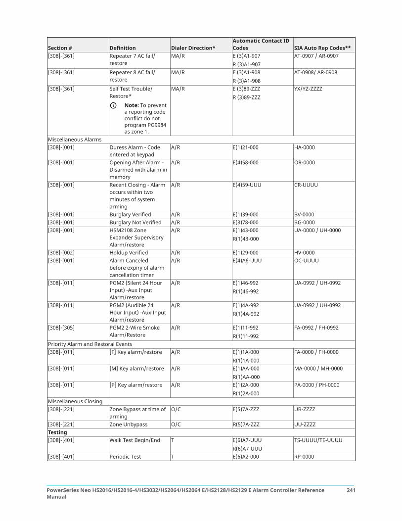
Section # Definition Dialer Direction*Automatic Contact IDCodes SIA Auto Rep Codes**
[308]-[361] Repeater 7 AC fail/restore
MA/R E (3)A1-907R (3)A1-907
AT-0907 / AR-0907
[308]-[361] Repeater 8 AC fail/restore
MA/R E (3)A1-908R (3)A1-908
AT-0908/ AR-0908
[308]-[361] Self Test Trouble/Restore*
Note: To preventa reporting codeconflict do notprogram PG9984as zone 1.
MA/R E (3)89-ZZZR (3)89-ZZZ
YX/YZ-ZZZZ
Miscellaneous Alarms[308]-[001] Duress Alarm - Code
entered at keypadA/R E(1)21-000 HA-0000
[308]-[001] Opening After Alarm -Disarmed with alarm inmemory
A/R E(4)58-000 OR-0000
[308]-[001] Recent Closing - Alarmoccurs within twominutes of systemarming
A/R E(4)59-UUU CR-UUUU
[308]-[001] Burglary Verified A/R E(1)39-000 BV-0000[308]-[001] Burglary Not Verified A/R E(3)78-000 BG-0000[308]-[001] HSM2108 Zone
Expander SupervisoryAlarm/restore
A/R E(1)43-000R(1)43-000
UA-0000 / UH-0000
[308]-[002] Holdup Verified A/R E(1)29-000 HV-0000[308]-[001] Alarm Canceled
before expiry of alarmcancellation timer
A/R E(4)A6-UUU OC-UUUU
[308]-[011] PGM2 (Silent 24 HourInput) -Aux InputAlarm/restore
A/R E(1)46-992R(1)46-992
UA-0992 / UH-0992
[308]-[011] PGM2 (Audible 24Hour Input) -Aux InputAlarm/restore
A/R E(1)4A-992R(1)4A-992
UA-0992 / UH-0992
[308]-[305] PGM2 2-Wire SmokeAlarm/Restore
A/R E(1)11-992R(1)11-992
FA-0992 / FH-0992
Priority Alarm and Restoral Events[308]-[011] [F] Key alarm/restore A/R E(1)1A-000
R(1)1A-000FA-0000 / FH-0000
[308]-[011] [M] Key alarm/restore A/R E(1)AA-000R(1)AA-000
MA-0000 / MH-0000
[308]-[011] [P] Key alarm/restore A/R E(1)2A-000R(1)2A-000
PA-0000 / PH-0000
Miscellaneous Closing[308]-[221] Zone Bypass at time of
armingO/C E(5)7A-ZZZ UB-ZZZZ
[308]-[221] Zone Unbypass O/C R(5)7A-ZZZ UU-ZZZZTesting[308]-[401] Walk Test Begin/End T E(6)A7-UUU
R(6)A7-UUUTS-UUUU/TE-UUUU
[308]-[401] Periodic Test T E(6)A2-000 RP-0000
241PowerSeries Neo HS2016/HS2016-4/HS3032/HS2064/HS2064 E/HS2128/HS2129 E Alarm Controller ReferenceManual

Section # Definition Dialer Direction*Automatic Contact IDCodes SIA Auto Rep Codes**
[308]-[401] Periodic Test withTrouble
T E(6)A8-000 RY-0000
[308]-[401] System Test - [*][6] bell/communications test
T E(6)A1-000 RX-0000
Maintenance[308]-[311] General System
trouble/restore - An RFjam trouble occurred/was restored
MA/R E(3) AA-000R(3) AA-000
YX-0000 / YZ-0000
[308]-[311] Fire trouble/restore MA/R E(3)73-000R(3)73-000
FT-0000 / FJ-0000
[308]-[314] Gas trouble/restore MA/R E(3)8A-ZZZR(3)8A-ZZZ
GT-ZZZZ / GJ-ZZZZ
[308]-[314] Delinquency trouble/restore
MA/R E(6)54-000R(6)54-000
CD-0000
[308]-[314] Heat trouble/restore MA/R E(3)8A-ZZZR(3)8A-ZZZ
KT-ZZZZ / KJ-ZZZZ
[308]-[314] Freeze Trouble /Restore
MA/R E(3)8A - ZZZR(3)8A - ZZZ
ZT-ZZZZ / ZJ-ZZZZ
Carbon MonoxideTrouble
MA/R E(3)8A - ZZZR(3)8A - ZZZ
UT-ZZZZ / UJ-ZZZZ
[308]-[311] Cold Start - System hasrestarted after totalpower loss
MA/R R(3) A5-000 RR-0000
[308]-[312] Event Buffer 75% Full MA/R E(6)22-000 JL-0000[308]-[312] DLS Lead In - Download
session startMA/R E(4)11-000 RB-0000
[308]-[312] DLS Lead Out -Download session stop
MA/R E(4)12-000 RS-0000
[308]-[312] SA Lead In - Downloadsession start
MA/R E(4)11-000 RB-0000
[308]-[312] SA Lead Out - Downloadsession stop
MA/R E(4)12-000 RS-0000
[308]-[312] Installer Lead In -Installer Programminghas been entered
MA/R E(6)27-000 LB-0000
[308]-[312] Installer Lead out -Installer Programminghas been exited
MA/R E(6)28-000 LS-0000
[308]-[313] Panel firmware updatebegin/ successful
MA/R E(9)01-900R(9)01-900
LB-0900 / LS-0900
[308]-[313] Panel firmware updatefail
MA/R E(9)02-900 LU-0900
[308]-[321] Receiver 1 FTC TroubleRestore
MA/R R(3)54-001 YK-0001
[308]-[321] Receiver 2 FTC TroubleRestore
MA/R R(3)54-002 YK-0002
PowerSeries Neo HS2016/HS2016-4/HS3032/HS2064/HS2064 E/HS2128/HS2129 E Alarm Controller ReferenceManual
242

Section # Definition Dialer Direction*Automatic Contact IDCodes SIA Auto Rep Codes**
[308]-[321] Receiver 3 FTC TroubleRestore
MA/R R(3)54-003 YK-0003
[308]-[321] Receiver 4 FTC TroubleRestore
MA/R R(3)54-004 YK-0004
******
A/R = alarms/restores; T/R = tampers/restorers; O/C = openings/closings; MA/R = maintenancealarms/restores; T = test transmissionsUUU = user number (user 001-1000). Note that for CID, enter 999 for user 1000. ZZZ/ZZZZ = zonenumber (001-128).Zones and panic pendants are identified, wireless keys can be identified for openings and closings.
Contact ID & SIA Zone Alarm/Restore Event Codes (as per SIA DCS: ‘Contact ID’ 01-1999):The table below defines the meaning of all Contact ID and SIA zone alarm/restore event codes.
Zone Definition SIA Auto Rep Codes Contact ID Auto Rep CodesDelay 1 BA-ZZZZ / BH-ZZZZ E(1) 3A - ZZZ / R(1)3A- ZZZDelay 2 BA-ZZZZ / BH-ZZZZ E(1) 3A - ZZZ / R(1)3A- ZZZInstant BA-ZZZZ / BH-ZZZZ E(1) 3A - ZZZ / R(1)3A- ZZZInterior BA-ZZZZ / BH-ZZZZ E(1) 3A - ZZZ / R(1)3A- ZZZInterior Stay/Away BA-ZZZZ / BH-ZZZZ E(1) 3A - ZZZ / R(1)3A- ZZZDelay Stay/Away BA-ZZZZ / BH-ZZZZ E(1) 3A - ZZZ / R(1)3A- ZZZInstant Stay/Away BA-ZZZZ / BH-ZZZZ E(1) 3A - ZZZ / R(1)3A- ZZZInterior Delay BA-ZZZZ / BH-ZZZZ E(1) 3A - ZZZ / R(1)3A- ZZZDay Zone BA-ZZZZ / BH-ZZZZ E(1) 3A - ZZZ / R(1)3A- ZZZNight Zone BA-ZZZZ / BH-ZZZZ E(1) 3A - ZZZ / R(1)3A- ZZZ24-Hr. Burglary BA-ZZZZ / BH-ZZZZ E(1) 3A - ZZZ / R(1)3A- ZZZDelayed 24-Hr. Fire (Wireless) FA-ZZZZ / FH-ZZZZ E(1) 1A - ZZZ / R(1)1A - ZZZStandard 24-Hr. Fire (Wireless) FA-ZZZZ / FH-ZZZZ E(1) 1A - ZZZ / R(1)1A - ZZZ24-Hr. Sprinkler SA-ZZZZ / SH-ZZZZ E(1) 13 - ZZZ / R(1)13 - ZZZ24-Hr.Low Temperature ZA-ZZZZ / ZH-ZZZZ E(1) 59 - ZZZ / R(1)59-ZZZ24-Hr High Temperature KA-ZZZZ / KH-ZZZZ E(1) 58 - ZZZ / R(1)58 - ZZZ24-Hr. Latching Tamper BA-ZZZZ / BH-ZZZZ E(1) 3A - ZZZ / R(1)3A- ZZZ24-Hr. Non Alarm (Walk Test Only) BA-ZZZZ / BH-ZZZZ E(1) 3A - ZZZ / R(1)3A- ZZZ24-Hr. Non-latching Tamper TA-ZZZZ / TR-ZZZZ E(3) 83 - ZZZ / R(3)83 - ZZZMomentary Keyswitch Arm (Walk TestOnly)
BA-ZZZZ / BH-ZZZZ E(1) 3A - ZZZ / R(1)3A- ZZZ
Maintained Keyswitch Arm (Walk TestOnly)
BA-ZZZZ / BH-ZZZZ E(1) 3A - ZZZ / R(1)3A- ZZZ
Momentary Keyswitch Disarm (Walk TestOnly)
BA-ZZZZ / BH-ZZZZ E(1) 3A - ZZZ / R(1)3A- ZZZ
Maintained Keyswitch Disarm (Walk TestOnly)
BA-ZZZZ / BH-ZZZZ E(1) 3A - ZZZ / R(1)3A- ZZZ
24-Hr. Supervisory US-ZZZZ / UR-ZZZZ E(1) 5A - ZZZ / R(1)5A - ZZZ24-Hr. Supervisory Buzzer UA-ZZZZ / UH-ZZZZ E(1) 5A - ZZZ / R(1)5A - ZZZ24-Hr. Auto Verified Fire (Wireless) FA-ZZZZ / FH-ZZZZ E(1) 1A - ZZZ / R(1)1A - ZZZFire Supervisory FS-ZZZZ / FV-ZZZZ E(2) AA - ZZZ / R(2)AA - ZZZ24-Hr. Gas GA-ZZZZ / GH-ZZZZ E(1) 51 - ZZZ / R(1)51 - ZZZ24-Hr. CO Alarm GA-ZZZZ / GH-ZZZZ E(1) 62 - ZZZ / R(1)62 - ZZZ24-Hr. Holdup HA-ZZZZ / HH-ZZZZ E(1) 22 - ZZZ / R(1)22 - ZZZ24-Hr. Panic PA-ZZZZ / PH-ZZZZ E(1) 2A - ZZZ / R(1)2A - ZZZ24-Hr. Flood WA-ZZZZ / WH-ZZZZ E(1) 54 - ZZZ / R(1)54 - ZZZ24-Hr Heat KA-ZZZZ / KH-ZZZZ E(1) 58 - ZZZ / R(1)58 - ZZZ24-Hr. Medical MA-ZZZZ / MH-ZZZZ E(1) AA - ZZZ / R(1)AA - ZZZ24-Hr. Emergency QA-ZZZZ / QH-ZZZZ E(1) A1 - ZZZ / R(1)A1 - ZZZDoorbell Zone/Restore (Walk Test Only) BA-ZZZZ / BH-ZZZZ E(1) 3A - ZZZ / R(1)3A - ZZZ
243PowerSeries Neo HS2016/HS2016-4/HS3032/HS2064/HS2064 E/HS2128/HS2129 E Alarm Controller ReferenceManual

Zone Definition SIA Auto Rep Codes Contact ID Auto Rep CodesPush to Set (Walk Test Only) BA-ZZZZ / BH-ZZZZ E(1) 3A - ZZZ / R(1)3A - ZZZFinal Door Set BA-ZZZZ / BH-ZZZZ E(1) 3A - ZZZ / R(1)3A - ZZZZZZ/ZZZZ = zones 001-128
Word library1 Aborted 2 AC 3 Access 4 Active 5 Activity6 Alarm 7 All 8 AM 9 Area 10 Arm11 Armed 12 Arming 13 Attic 14 Auxiliary 15 Away16 Baby 17 Back 18 Bar 19 Basement 20 Bathroom21 Battery 22 Bedroom 23 Bonus 24 Bottom 25 Breezeway26 Building 27 Bus 28 Bypass 29 Bypassed 30 Cabinet31 Camera 32 Canceled 33 Car 34 Carbon 35 Central36 Chime 37 Closed 38 Closet 39 Closing 40 Code41 Communicator 42 Computer 43 Control 44 Date 45 Daughter’s46 Degrees 47 Delay 48 Den 49 Desk 50 Detector51 Dining 52 Disarmed 53 Door 54 Down 55 Download56 Downstairs 57 Drawer 58 Driveway 59 Duct 60 Duress61 East 62 Energy 63 Enter 64 Entry 65 Error66 Exercise 67 Exit 68 Exterior 69 Factory 70 Failure71 Family 72 Father’s 73 Feature 74 Fence 75 Fire76 First 77 Floor 78 Force 79 Foyer 80 Freeze81 Front 82 Furnace 83 Gallery 84 Garage 85 Gas86 Glass 87 Goodbye 88 Gym 89 Hallway 90 Heat91 Hello 92 Help 93 High 94 Home 95 House96 In 97 Install 98 Interior 99 Intrusion 100 Invalid101 Is 102 Key 103 Kids 104 Kitchen 105 Latchkey106 Laundry 107 Left 108 Level 109 Library 110 Light111 Lights 112 Living 113 Load 114 Loading 115 Low116 Lower 117 Main 118 Master 119 Mat 120 Medical121 Memory 122 Menu 123 Monoxide 124 Mother’s 125 Motion126 No 127 North 128 Not 129 Now 130 Number131 Off 132 Office 133 OK 134 On 135 Open136 Opening 137 Panic 138 Partition 139 Patio 140 Pet141 Phone 142 Please 143 PM 144 Police 145 Pool146 Porch 147 Power 148 Press 149 Program 150 Progress151 Quiet 152 Rear 153 Receiver 154 Report 155 RF156 Right 157 Room 158 Safe 159 Saver 160 Schedule161 Screen 162 Second 163 Sensor 164 Service 165 Shed166 Shock 167 Shop 168 Side 169 Siren 170 Sliding171 Smoke 172 Son’s 173 Sound 174 South 175 Special176 Stairs 177 Stay 178 Sun 179 Supervisory 180 System181 Tamper 182 Temperature 183 Test 184 Time 185 To186 Touchpad 187 Trouble 188 Unbypass 189 Unit 190 Up191 West 192 Window 193 Zone 194 0 195 1196 2 197 3 198 4 199 5 200 6201 7 202 8 203 9 204 A 205 B206 C 207 D 208 E 209 F 210 G211 H 212 I 213 J 214 K 215 L216 M 217 N 218 O 219 P 220 Q221 R 222 S 223 T 224 U 225 V
PowerSeries Neo HS2016/HS2016-4/HS3032/HS2064/HS2064 E/HS2128/HS2129 E Alarm Controller ReferenceManual
244

226 W 227 X 228 Y 229 Z 230 (Space)231 ‘ (Apostrophe) 232 - (Dash) 233 _ (Underscore) 234 * 235 #236 : 237 / 238 ? 239 240
Template programming tablesThe following tables show the programming options for template programming digits 1-5.
Digit 1 – Zones 1-8 Definition OptionsNote: A “0” in the digit 1 location indicates that the first 8 zones use the panel default zonedefinitions.
Option Zone 1 Zone 2 Zone 3 Zone 4 Zone 5 Zone 6 Zone 7 Zone 8
ZoneDefinitions(Options 1-6)
1 001 003 003 003 004 004 004 004 001 Delay 12 001 003 003 005 005 005 005 008 003 Instant3 001 003 003 005 005 005 005 007 004 Interior4 001 001 003 003 003 003 003 003 005 Interior
Stay/Away5 001 003 003 006 005 005 005 005 006
DelayedStay/Away
6 001 003 003 006 005 005 005 008 007Delayed24Hr. Fire
7 (ADT) 001 001 006 006 006 001 001 001 008Standard24Hr. Fire(Wireless)
Digit 2 – System EOL Configuration OptionsOption EOL configuration [13] bit 1 [13] bit 21 NC Loops ON OFF2 SEOL OFF OFF3 DEOL OFF ON
245PowerSeries Neo HS2016/HS2016-4/HS3032/HS2064/HS2064 E/HS2128/HS2129 E Alarm Controller ReferenceManual
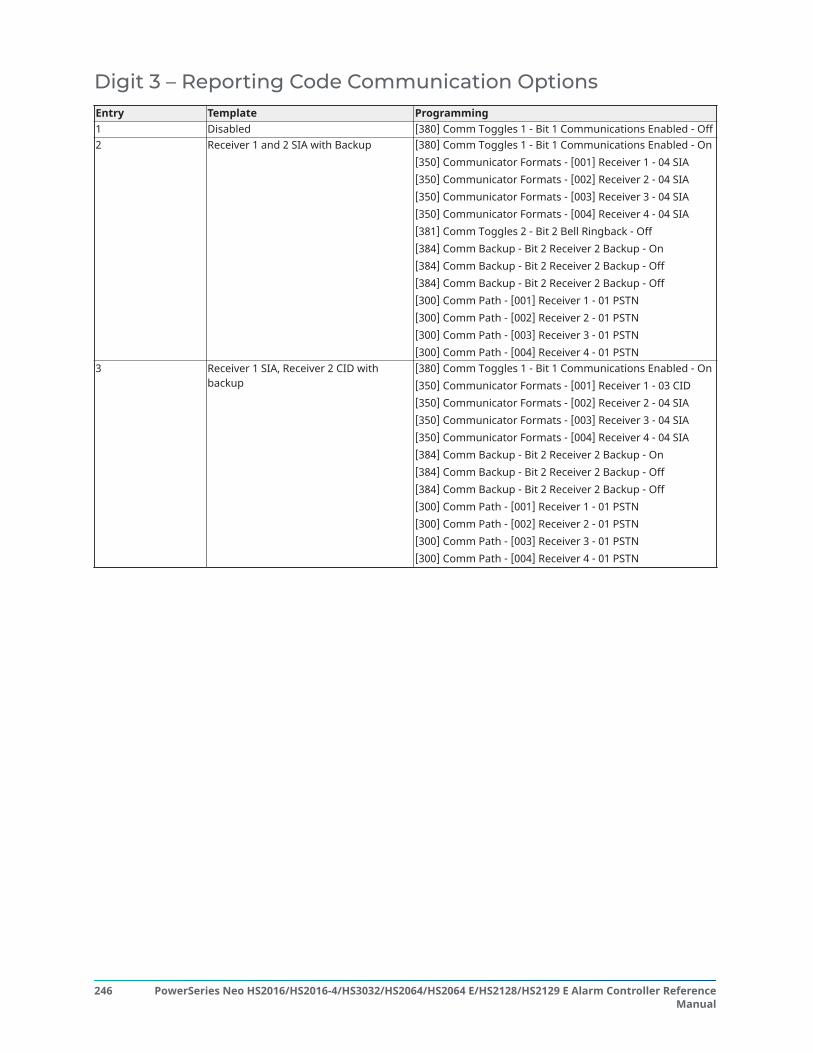
Digit 3 – Reporting Code Communication OptionsEntry Template Programming1 Disabled [380] Comm Toggles 1 - Bit 1 Communications Enabled - Off2 Receiver 1 and 2 SIA with Backup [380] Comm Toggles 1 - Bit 1 Communications Enabled - On
[350] Communicator Formats - [001] Receiver 1 - 04 SIA[350] Communicator Formats - [002] Receiver 2 - 04 SIA[350] Communicator Formats - [003] Receiver 3 - 04 SIA[350] Communicator Formats - [004] Receiver 4 - 04 SIA[381] Comm Toggles 2 - Bit 2 Bell Ringback - Off[384] Comm Backup - Bit 2 Receiver 2 Backup - On[384] Comm Backup - Bit 2 Receiver 2 Backup - Off[384] Comm Backup - Bit 2 Receiver 2 Backup - Off[300] Comm Path - [001] Receiver 1 - 01 PSTN[300] Comm Path - [002] Receiver 2 - 01 PSTN[300] Comm Path - [003] Receiver 3 - 01 PSTN[300] Comm Path - [004] Receiver 4 - 01 PSTN
3 Receiver 1 SIA, Receiver 2 CID withbackup
[380] Comm Toggles 1 - Bit 1 Communications Enabled - On[350] Communicator Formats - [001] Receiver 1 - 03 CID[350] Communicator Formats - [002] Receiver 2 - 04 SIA[350] Communicator Formats - [003] Receiver 3 - 04 SIA[350] Communicator Formats - [004] Receiver 4 - 04 SIA[384] Comm Backup - Bit 2 Receiver 2 Backup - On[384] Comm Backup - Bit 2 Receiver 2 Backup - Off[384] Comm Backup - Bit 2 Receiver 2 Backup - Off[300] Comm Path - [001] Receiver 1 - 01 PSTN[300] Comm Path - [002] Receiver 2 - 01 PSTN[300] Comm Path - [003] Receiver 3 - 01 PSTN[300] Comm Path - [004] Receiver 4 - 01 PSTN
PowerSeries Neo HS2016/HS2016-4/HS3032/HS2064/HS2064 E/HS2128/HS2129 E Alarm Controller ReferenceManual
246

Entry Template Programming4 Receiver 1 SIA [380] Comm Toggles 1 - Bit 1 Communications Enabled - On
[350] Communicator Formats - [001] Receiver 1 - 04 SIA[350] Communicator Formats - [002] Receiver 2 - 04 SIA[350] Communicator Formats - [003] Receiver 3 - 04 SIA[350] Communicator Formats - [004] Receiver 4 - 04 SIA[381] Comm Toggles 2 - Bit 2 Bell Ringback - Off[384] Comm Backup - Bit 2 Receiver 2 Backup - Off[384] Comm Backup - Bit 2 Receiver 2 Backup - Off[384] Comm Backup - Bit 2 Receiver 2 Backup - Off[300] Comm Path - [001] Receiver 1 - 01 PSTN[300] Comm Path - [002] Receiver 2 - 01 PSTN[300] Comm Path - [003] Receiver 3 - 01 PSTN[300] Comm Path - [004] Receiver 4 - 01 PSTN
5 Receiver 1 CID [380] Comm Toggles 1 - Bit 1 Communications Enabled - On[350] Communicator Formats - [001] Receiver 1 - 03 CID[350] Communicator Formats - [002] Receiver 2 - 03 CID[350] Communicator Formats - [003] Receiver 3 - 03 CID[350] Communicator Formats - [004] Receiver 4 - 03 CID[384] Comm Backup - Bit 2 Receiver 2 Backup - Off[384] Comm Backup - Bit 2 Receiver 2 Backup - Off[384] Comm Backup - Bit 2 Receiver 2 Backup - Off[300] Comm Path - [001] Receiver 1 - 01 PSTN[300] Comm Path - [002] Receiver 2 - 01 PSTN[300] Comm Path - [003] Receiver 3 - 01 PSTN[300] Comm Path - [004] Receiver 4 - 01 PSTN
6 Receiver 1 and 2 CIA with backup [380] Comm Toggles 1 - Bit 1 Communications Enabled - On[350] Communicator Formats - [001] Receiver 1 - 03 CID[350] Communicator Formats - [002] Receiver 2 - 03 CID[350] Communicator Formats - [003] Receiver 3 - 03 CID[350] Communicator Formats - [004] Receiver 4 - 03 CID[384] Comm Backup - Bit 2 Receiver 2 Backup - On[384] Comm Backup - Bit 2 Receiver 2 Backup - Off[384] Comm Backup - Bit 2 Receiver 2 Backup - Off[300] Comm Path - [001] Receiver 1 - 01 PSTN[300] Comm Path - [002] Receiver 2 - 01 PSTN[300] Comm Path - [003] Receiver 3 - 01 PSTN[300] Comm Path - [004] Receiver 4 - 01 PSTN
Digit 4 – Reporting Code Configuration Options
Option Common Selected TroublesOpenings/Closings
Zone AlarmRestore
DLS/Installer LeadIn/Out
1 i i X
2 i i i X
3 i i i X
4 i i i i X5 i i X
6 i i X
247PowerSeries Neo HS2016/HS2016-4/HS3032/HS2064/HS2064 E/HS2128/HS2129 E Alarm Controller ReferenceManual

Option Common Selected TroublesOpenings/Closings
Zone AlarmRestore
DLS/Installer LeadIn/Out
7 i i i X
8 i
i indicates included, blank indicates default setting, X indicates disabled
Common GroupCommon Group Common Group ProgrammingSet all reporting codes to automatic [308] Event Reporting - All Events OnAlarm/restore call directions enabled [311][001] Partition 1 Alarm/Restore - Bit 1 Receiver 1 - On
[311][001] Partition 1 Alarm/Restore - Bit 2 Receiver 2 - Off[311][001] Partition 1 Alarm/Restore - Bit 3 Receiver 3 - Off[311][001] Partition 1 Alarm/Restore - Bit 4 Receiver 4 - Off
Tamper/restore call directions disabled [311][002] Partition 1 Tamper/Restore - Bit 1 Receiver 1 - Off[311][002] Partition 1 Tamper/Restore - Bit 2 Receiver 2 - Off[311][002] Partition 1 Tamper/Restore - Bit 3 Receiver 3 - Off[311][002] Partition 1 Tamper/Restore - Bit 4 Receiver 4 - Off
Opening/closing call directions disabled [311][003] Partition 1 Open/Close - Bit 1 Receiver 1 - Off[311][003] Partition 1 Open/Close - Bit 2 Receiver 2 - Off[311][003] Partition 1 Open/Close - Bit 3 Receiver 3 - Off[311][003] Partition 1 Open/Close - Bit 4 Receiver 4 - Off
Maintenance call directions enabled [309][001] Maintenance - Bit 1 Receiver 1 - On[309][001] Maintenance - Bit 2 Receiver 2 - Off[309][001] Maintenance - Bit 3 Receiver 3 - Off[309][001] Maintenance - Bit 4 Receiver 4 - Off
Test transmission call directions disabled [309][002] Test Transmission - Bit 1 Receiver 1 - Off[309][002] Test Transmission - Bit 2 Receiver 2 - Off[309][002] Test Transmission - Bit 3 Receiver 3 - Off[309][002] Test Transmission - Bit 4 Receiver 4 - Off
• Enables/Disables all Reporting Codes• Selected Troubles - Enables the following Troubles
PowerSeries Neo HS2016/HS2016-4/HS3032/HS2064/HS2064 E/HS2128/HS2129 E Alarm Controller ReferenceManual
248

Selected Troubles Group Selected Troubles ProgrammingBattery [308][301] - Bit 3 Panel Low Battery - On
[308][301] - Bit 4 Panel Low Battery Restore - On
[308][301] - Bit 5 Panel Battery Absent - On
[308][301] - Bit 6 Panel Battery Absent Restore -On
[308][331] - Bit 3 Module Low Battery - On
[308][331] - Bit 4 Module Low Battery Restore -On
[308][331] - Bit 5 Module Battery Absent - On
[308][331] - Bit 6 Module Battery Absent Restore- On
AC Failure [308][301] - Bit 1 Panel AC Trouble - Off
[308][301] - Bit 2 Panel AC Trouble Restore - Off
[308][331] - Bit 1 Module AC Trouble - Off
[308][331] - Bit 2 Module AC Trouble Restore -Off
Bell Circuit Trouble [308][302] - Bit 1 Panel Bell Trouble - On
[308][302] - Bit 2 Panel Bell Trouble Restore - OnFire, Alarm [308][311] - Bit 3 Fire Trouble - On
[308][311] - Bit 4 Fire Trouble Restore - On
[308][305] - Bit 3 2W Smoke Trouble - On
[308][305] - Bit 4 2W Smoke Trouble Restore -On
Aux Power Supply Trouble [308][302] - Bit 5 Panel AUX Trouble - On
[308][302] - Bit 6 Panel AUX Trouble Restore - On
[308][332] - Bit 5 Module AUX Trouble - On
[308][332] - Bit 6 Module AUX Trouble Restore -On
249PowerSeries Neo HS2016/HS2016-4/HS3032/HS2064/HS2064 E/HS2128/HS2129 E Alarm Controller ReferenceManual

Selected Troubles Group Selected Troubles ProgrammingTLM Trouble [308][302] - Bit 3 Panel TLM Trouble - Off
[308][302] - Bit 4 Panel TLM Trouble Restore - OnGeneral System Tamper [308][101] - Bit 3 Module Tamper Trouble - Off
[308][101] - Bit 4 Module Tamper Restore - OffGeneral System Supervisory [308][332] - Bit 3 Module Supervisory Trouble -
On
[308][332] - Bit 4 Module Supervisory Restore -On
• Openings & Closings - Sets Residential Dial Reporting Codes for all openings and closingsOpenings/Closings Group Openings/Closings ProgrammingEnable All User Open/Close Reports [308][201] - Bit 1 User Closing - On
[308][201] - Bit 2 User Opening - On
[308][201] - Bit 5 Special Closing - On
[308][201] - Bit 6 Special Opening - On
[308][202] - Bit 1 Automatic Closing - On
[308][202] - Bit 2 Automatic Opening - On
[308][202] - Bit 3 Automatic Cancel - On
• Zone Alarm Restore Group - Disables all zone alarm restore reporting codesZone Alarm Restore Group DLS/Installer Lead In/Out ProgrammingRestore zone alarm reporting codes [307][001] - Bit 2 Alarm Restore - Off
[307][002] - Bit 2 Alarm Restore - Off
[307][003] - Bit 2 Alarm Restore - Off
[307][004] - Bit 2 Alarm Restore - Off
[307][005] - Bit 2 Alarm Restore - Off
[307][006] - Bit 2 Alarm Restore - Off
[307][007] - Bit 2 Alarm Restore - Off
[307][008] - Bit 2 Alarm Restore - Off
[307][009] - [128] Bit 2 Alarm Restore - Off
• Installer Lead-in/Lead-out and DLS Lead-in/Lead-out
PowerSeries Neo HS2016/HS2016-4/HS3032/HS2064/HS2064 E/HS2128/HS2129 E Alarm Controller ReferenceManual
250

DLS/Installer Lead In/Out Group DLS/Installer Lead In/Out ProgrammingDLS/Installer Disabled [308][312] - Bit 1 Installer Lead In - Off
[308][312] - Bit 2 Installer Lead Out - Off
[308][312] - Bit 3 DLS Lead In - Off
[308][312] - Bit 4 DLS Lead Out - Off
[308][312] - Bit 5 SA Lead In - Off
[308][312] - Bit 6 SA Lead Out - Off
Digit 5 - DLS Connection OptionsOption Programming section DLS connection/call back setting1 [401] Option 1 OFF
Option 3 OFFOption 4 OFF[406] 000
Double Call DisabledCall Back DisabledUser Initiated Call Up DisabledNumber of Rings to Answer On Disabled
2 [401] Option 1 ONOption 3 OFFOption 4 OFF[406] 008
Double Call EnabledCall Back DisabledUser Initiated Call Up DisabledNumber of Rings to Answer On is 8
3 [401] Option 1 ONOption 3 ONOption 4 OFF[406] 008
Double Call EnabledCall Back EnabledUser Initiated Call Up DisabledNumber of Rings to Answer On is 8
4 [401] Option 1 ONOption 3 OFFOption 4 ON[406] 008
Double Call EnabledCall Back DisabledUser Initiated Call Up EnabledNumber of Rings to Answer On is 8
After entering a valid 5-digit template programming code, the system prompts for the followingdata in the sequence listed:
1. Central Station Telephone Number1. Program the required central station phone number. Press [#] to complete your entry.
This phone number is entered into programming section [301][001].
2. Central Station System Account Code (4 or 6-digit code)3. Program the system account code. All digits must be entered in order to complete your
entry.This account code is entered into programming section [310][000].
4. Partition 1 Account Code (4 digit code)5. Program the partition 1 account code. All digits must be entered in order to complete
your entry.This account code is entered into programming section [310][001].
6. DLS Access Code (6-digit code)
251PowerSeries Neo HS2016/HS2016-4/HS3032/HS2064/HS2064 E/HS2128/HS2129 E Alarm Controller ReferenceManual

7. Program the required DLS access code. All 6 digits must be entered in order to completeyour entry.This access code is entered into programming section [403].
8. Entry Delay 1 and Exit Delay9. Enter the 3-digit entry delay 1 (in seconds) followed by the desired 3-digit exit delay (in
seconds). These entries affect all partitions.All 3 digits must be entered in order to complete each section entry.These values are entered in programming sections [005][001]-[008] entry 1 and 3respectively.
10. Installer's Code11. Enter the 4, 6 or 8-digit installer access code (dependent on section [041]). All digits must
be entered in order to complete the section entry.This code is entered into programming section [006][001].After the installer code has been programmed the system returns to the base installerprogramming menu.All template programming information defaults after performing a hardware or softwarepanel default. The 5-digit template programming code is defaulted to 0000000.
Note: Pressing the pound key (#) advances through template programming, accepting what isdisplayed in these locations, potentially overwriting desired programming. Depending on theoption programmed, restoring the defaults using template programming may not be possible.
ASCII Characters! “ # $ % & ‘ ( ) * + , - . / 0 1 2 3 4 5 6 7 833 34 35 36 37 38 39 40 41 42 43 44 45 46 47 48 49 50 51 52 53 54 55 569 : ; < = > ? @ A B C D E F G H I J K L M N O P57 58 59 60 61 62 63 64 65 66 67 68 69 70 71 72 73 74 75 76 77 78 79 80Q R S T U V W X Y Z [ ¥ ] ^ _ ╲ a b c d e f g h81 82 83 84 85 86 87 88 89 90 91 92 93 94 95 96 97 98 99 100 101 102 103 104i j k l m n o p q r s t u v w x y z { ׀ } → ←
105 106 107 108 109 110 111 112 113 114 115 116 117 118 119 120 121 122 123 124 125 126 127 160□ 「 」 ▪ ヲ ア ィ ゥ ェ ォ カ ュ ョ シ ᅳ ア イ ゥ ェ ォ カ キ ク
161 162 163 164 165 166 167 168 169 170 171 172 173 174 175 176 177 178 179 180 181 182 183 184ケ コ サ シ ス セ ソ タ ダ ツ テ ト ナ ニ ヌ ネ ノ ハ ヒ フ ヘ ホ マ ミ185 186 187 188 189 190 191 192 193 194 195 196 197 198 199 200 201 202 203 204 205 206 207 208ム メ モ ヤ ユ ョ ラ リ ル レ ロ ワ ン ? ▢ α ä β Ɛ μ σ ρ ϧ ʃ209 210 211 212 213 214 215 216 217 218 219 220 221 222 223 224 225 226 227 228 229 230 231 232⊣ ϳ x ¢ £ ñ Ö p q θ œ Ω ϋ Σ π X y 千 Ⴌ Ħ ÷
233 234 235 236 237 238 239 240 241 242 243 244 245 246 247 248 249 250 251 252 253
Wiring diagrams
PowerSeries Neo HS2016/HS2016-4/HS3032/HS2064/HS2064 E/HS2128/HS2129 E Alarm Controller ReferenceManual
252

HS2016, HS2032, HS2064, HS2128 UL/ULC Wiring Diagram
253PowerSeries Neo HS2016/HS2016-4/HS3032/HS2064/HS2064 E/HS2128/HS2129 E Alarm Controller ReferenceManual

Zone Wiring
Bell Wiring
PowerSeries Neo HS2016/HS2016-4/HS3032/HS2064/HS2064 E/HS2128/HS2129 E Alarm Controller ReferenceManual
254

PGM Wiring
Telephone line wiring
Note: For ULC installations, please refer to the ULC Installation Information Sheet part#29002157.
255PowerSeries Neo HS2016/HS2016-4/HS3032/HS2064/HS2064 E/HS2128/HS2129 E Alarm Controller ReferenceManual

Neo Reference Manual Feature ChangesV1.35
• When Access Code Required for [*][2] enabled, trouble beeps are silenced when the [*][2]menu has been entered and exited.
• New "Bell Silenced" message displayed after a fire or CO alarm is silenced with a user code.• New PG devices supported.• When [377][004] programmed with value 0445, panel generates randomized test transmission.• Panel requests 2 images from each enrolled PIR Cam and sends to monitoring station during a
system test.
V1.31
• Fixed an issue for Burglary Verification when set to Cross Zoning.• After a burglary verification alarm was sent, subsequent alarms without burglary verification
enabled were not transmitted.
V1.3
• 5-Digit Remote Reset Code: Replaces existing 4-Digit Remote Reset feature.• Increased Proximity Tag Arming Flexibility: Proximity tag can always arm in Away Mode, or
detect appropriate arming mode.• Bell circuit damage caused by reverse polarity applied at Bell+ and Bell- : Bell circuit now
accommodates reversing relay modules.• CO Alarm followed Bell Timeout: CO Alarm now follows the Temporal CO pattern until Bell
Timeout is reached, and then switches to 60s interval (Extended CO Cadence) until the alarm isacknowledged.
V1.21
• CP-01 Variant Auto-Arm in Stay Mode: CP-01 Variant now Auto Arms correctly in Away Mode.
V1.2
• Increased number of users: Allows for larger installations.• Multi-partner integration: Allows interactive, access control and video within one intrusion
platform (version 5.x of the communicator is required).• Wireless Interconnected smoke alarms: o Triggers all wireless smoke detectors to sound when
one goes into alarm.• Global keypad support: management of multi-partition systems.• Proximity tag control of PGM outputs.• Toggle option to control PGM activation at beginning or end of exit delay: PGM activation can
be customized to activate at the beginning or end of exit delay for hardwired integration withother devices
• Toggle option to disable door chime during quick exit: When using quick exit to leave thepremise, keypads will not sound a door chime.
• Siren options for buzzer notification, door chime and trouble beep.
PowerSeries Neo HS2016/HS2016-4/HS3032/HS2064/HS2064 E/HS2128/HS2129 E Alarm Controller ReferenceManual
256
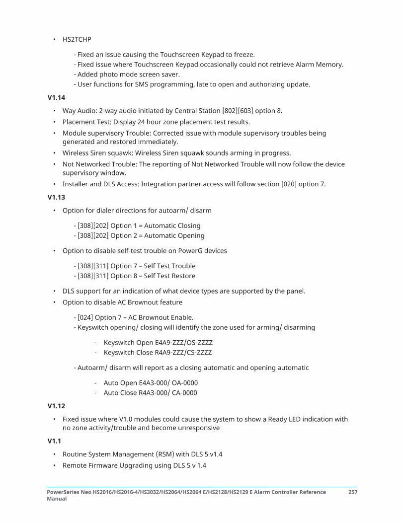
• HS2TCHP
- Fixed an issue causing the Touchscreen Keypad to freeze.- Fixed issue where Touchscreen Keypad occasionally could not retrieve Alarm Memory.- Added photo mode screen saver.- User functions for SMS programming, late to open and authorizing update.
V1.14
• Way Audio: 2-way audio initiated by Central Station [802][603] option 8.• Placement Test: Display 24 hour zone placement test results.• Module supervisory Trouble: Corrected issue with module supervisory troubles being
generated and restored immediately.• Wireless Siren squawk: Wireless Siren squawk sounds arming in progress.• Not Networked Trouble: The reporting of Not Networked Trouble will now follow the device
supervisory window.• Installer and DLS Access: Integration partner access will follow section [020] option 7.
V1.13
• Option for dialer directions for autoarm/ disarm
- [308][202] Option 1 = Automatic Closing- [308][202] Option 2 = Automatic Opening
• Option to disable self-test trouble on PowerG devices
- [308][311] Option 7 – Self Test Trouble- [308][311] Option 8 – Self Test Restore
• DLS support for an indication of what device types are supported by the panel.• Option to disable AC Brownout feature
- [024] Option 7 – AC Brownout Enable.- Keyswitch opening/ closing will identify the zone used for arming/ disarming
- Keyswitch Open E4A9-ZZZ/OS-ZZZZ- Keyswitch Close R4A9-ZZZ/CS-ZZZZ
- Autoarm/ disarm will report as a closing automatic and opening automatic
- Auto Open E4A3-000/ OA-0000- Auto Close R4A3-000/ CA-0000
V1.12
• Fixed issue where V1.0 modules could cause the system to show a Ready LED indication withno zone activity/trouble and become unresponsive
V1.1
• Routine System Management (RSM) with DLS 5 v1.4• Remote Firmware Upgrading using DLS 5 v 1.4
257PowerSeries Neo HS2016/HS2016-4/HS3032/HS2064/HS2064 E/HS2128/HS2129 E Alarm Controller ReferenceManual

• Global keypad menu changes• New Zone selections (Final Door Set and Push to Set)• Support for Neo Touchscreen HS2TCHP, 2-way Audio Module HSM2955 and Alarm.com
Communicators
V1.02
• Fixed Late to Close Reporting so that the correct identifier is sent
- For Contact ID, correct identifier ‘E’ is sent instead of the incorrect ‘R’- For SIA, correct reporting code ‘CJ’ is sent instead of the incorrect ‘CI’
• Fixed issue where firmware upgrade of the panel caused all programming sections to bedefaulted and modules to be unresponsive
V1.01
• Initial launch version of PowerSeries Neo
Regulatory Approvals
Regulatory Approvals
Regulatory Approvals
FCC COMPLIANCE STATEMENT
CAUTION: Changes or modifications not expressly approved by Digital Security Controls couldvoid your authority to use this equipment.
This equipment has been tested and found to comply with the limits for a Class B digital device,pursuant to Part 15 of the FCC Rules. These limits are designed to provide reasonable protectionagainst harmful interference in a residential installation. This equipment generates, uses and canradiate radio frequency energy and, if not installed and used in accordance with the instructions,may cause harmful interference to radio communications. However, there is no guarantee thatinterference will not occur in a particular installation. If this equipment does cause harmfulinterference to radio or television reception, which can be deter-mined by turning the equipmentoff and on, the user is encouraged to try to correct the interference by one or more of the followingmeasures:
• Re-orient the receiving antenna.• Increase the separation between the equipment and receiver.• Connect the equipment into an outlet on a circuit different from that to which the receiver is
connected.• Consult the dealer or an experienced radio/television technician for help.
The user may find the following booklet prepared by the FCC useful: "How to Identify and ResolveRadio/Television Interference Problems". This booklet is available from the U.S. GovernmentPrinting Office, Washington D.C. 20402, Stock # 004-000-00345-4.IMPORTANT INFORMATIONThis equipment complies with Part 68 of the FCC Rules. On the side of this equipment is a label thatcontains, among other information, the FCC registration number and ringer equivalence number(REN) for this equipment. If requested, this number must be provided to the Telephone Company.
PowerSeries Neo HS2016/HS2016-4/HS3032/HS2064/HS2064 E/HS2128/HS2129 E Alarm Controller ReferenceManual
258

HS2128 Product Identifier US: F53AL01BHS2128REN: 0.1B; USOC Jack: RJ-31XTelephone Connection RequirementsA plug and jack used to connect this equipment to the premises wiring and telephone networkmust comply with the applicable FCC Part 68 rules and requirements adopted by the ACTA. Acompliant telephone cord and modular plug is provided with this product. It is designed to beconnected to a compatible modular jack that is also compliant. See installation instructions fordetails.Ringer Equivalence Number (REN)The REN is used to determine the number of devices that may be connected to a telephone line.Excessive RENs on a telephone line may result in the devices not ringing in response to an incomingcall. In most but not all areas, the sum of RENs should not exceed five (5.0). To be certain of thenumber of devices that may be connected to a line, as determined by the total RENs, contact thelocal Telephone Company. For products approved after July 23, 2001, the REN for this product is partof the product identifier that has the format.US: AAAEQ##TXXXX. The digits represented by ## are the REN without a decimal point (e.g., 03 is aREN of 0.3). For earlier products, the REN is separately shown on the label.Incidence of HarmIf this equipment HS2016/HS2032/HS2064/HS2128 causes harm to the telephone network, thetelephone company will notify you in advance that temporary discontinuance of service may berequired. But if advance notice is not practical, the Telephone Company will notify the customeras soon as possible. Also, you will be advised of your right to file a complaint with the FCC if youbelieve it is necessary.Changes in Telephone Company Equipment or FacilitiesThe Telephone Company may make changes in its facilities, equipment, operations or proceduresthat could affect the operation of the equipment. If this happens the Telephone Company willprovide advance notice in order for you to make necessary modifications to maintain uninterruptedservice.Equipment Maintenance FacilityIf trouble is experienced with this equipment HS2016/HS2032/HS2064/HS2128 for repair orwarranty information, please contact the facility indicated below. If the equipment is causing harmto the telephone network, the Telephone Company may request that you disconnect the equipmentuntil the problem is solved. This equipment is of a type that is not intended to be repaired by theend user. Tyco Atlanta Distribution Center 2600 West Pointe Dr. Lithia Springs, GA 30122Additional InformationConnection to party line service is subject to state tariffs. Contact the state public utilitycommission, public service commission or corporation commission for information.Alarm dialling equipment must be able to seize the telephone line and place a call in an emergencysituation, even if other equipment (telephone, answering system, computer modem, etc.) alreadyhas the telephone line in use. To do so, alarm dialling equipment must be connected to a properlyinstalled RJ-31X jack that is electrically in series with and ahead of all other equipment attached tothe same telephone line. Proper installation is depicted in the figure below. Consult your telephonecompany or a qualified installer if you have any questions concerning these instructions or aboutinstalling the RJ-31X jack and alarm dialling equipment for you.
259PowerSeries Neo HS2016/HS2016-4/HS3032/HS2064/HS2064 E/HS2128/HS2129 E Alarm Controller ReferenceManual

ISED STATEMENTNOTICE: This Equipment, HS2016/HS2032/HS2064/HS2128, meets the applicable ISED TerminalEquipment Technical Specifications. This is confirmed by the registration number. The abbreviation,IC, before the registration number signifies that registration was performed based on a Declarationof Conformity indicating that ISED technical specifications were met. It does not imply that ISEDapproved the equipment.NOTICE: The Ringer Equivalence Number (REN) for this terminal equipment is 0.1. The RENassigned to each terminal equipment provides an indication of the maximum number of terminalsallowed to be connected to a telephone interface. The termination on an interface may consist ofany combination of devices subject only to the requirement that the sum of the Ringer EquivalenceNumbers of all devices does not exceed five.Certification Number:IC: 160A-HS2128; This Class B digital apparatus complies with CanadianICES-003.
UL/ULC InstallationsThis product (HS2016/HS2032/HS2064/HS2128) has been tested and found in compliance with thefollowing standards:
• UL1610 Central-Station Burglar-Alarm Units• UL365 Police Station Connected Burglar Alarm Units and Systems• UL1023 Household Burglar-Alarm System Units• UL985 Household Fire Warning System Units• UL1635 Digital Alarm Communicator System Units• UL1637 Home Health Care Signaling Equipment• ULC-S304-16 Rev1 Signal Receiving Centre & Premise Burglar Alarm Control Units• ULC-S559-13 Equipment for Fire Signal Receiving Centers and Systems• ULC-S545-02 Residential Fire Warning System Control Units• ORD-C1023-1974 Household Burglar-Alarm System Units
This product has also been tested and found in compliance with the ANSI/SIA CP-01-2010 ControlPanel Standard – Features for False Alarm Reduction. This product is UL/ULC listed under thefollowing categories:
• AMCX/AMCXC Central Stations Alarm Units• APAW Police-station-connected Alarm Units• DAYRC Central Station Fire Alarm System Units• UTOU/UTOUC Control Units and Accessories, Household System Type• NBSX/NBSXC Household Burglar Alarm System Units
PowerSeries Neo HS2016/HS2016-4/HS3032/HS2064/HS2064 E/HS2128/HS2129 E Alarm Controller ReferenceManual
260

• AMTB Control Panels, SIA False Alarm Reduction
The product is labeled with the UL and ULC listing marks along with the SIA CP-01 compliancestatement (Also Classified in accordance with SIA-CP-01 Standard) as proof of compliance with theabove mentioned standards. For further information on this product’s listings please also referto the official listing guides published at the UL web site (www.ul.com) under Online DirectionsSection.
UL/ULC Residential Fire and Burglary Installations:For ULC Installations refer to the Standard for the Installation of Residential Fire Warning Systems,CAN/ULC-S540.
• All burglary-type zones shall be configured with SEOL or DEOL configuration. Use modelEOLR-2 (refer to section [002], bit 10 or 11 shall be ON)
• Use at least one PG9936/PG9926/PG9916 Smoke Detector for Fire Installations (section [001],fire zone shall be programmed as type 025)
• The entry delay shall not exceed 45 seconds (see section [005])• The exit delay shall not exceed 60 seconds (refer to section [005])• The minimum Bell Time-out is 4 minutes (refer to section [005])
Note: For UL Commercial Burglary installations, minimum bell time-out is 15 min.
• Temporal Three Fire Signal shall be enabled (section [013], option 8 ON)• Arm/Disarm Bell Squawk shall be enabled when using wireless key PG4939/PG4929/PG4949
(section [014], option 1 shall be ON)• A code shall be required for bypassing (section [023], option 4 shall be ON)• Trouble beeps shall be enabled (section [022], option 7 shall be ON)• For fire and CO applications, RM-1(C) or RM-2 power loop supervision relay shall be connected
to Aux power output to report wiring faults if it is used for powering fire and CO detectiondevices. For wiring, see manual p/n: 29009812.
• AC trouble indication LED shall be enabled (Keypad Programming, section [022], options 5 and6 shall be ON)
• DACT Communicator shall be enabled for Supervising Station Monitoring (section [380], option1 shall be ON)
• For UL Residential Fire and burglary installations, a code shall be required to view the [*][2]trouble menu (Section [023], option 5 shall be ON)
• A test transmission shall be sent to the monitoring station every 7 days (Section [377][003]shall be set to 007; 007 is the default setting)
• For UL residential fire applications at least one LCD keypad (model HS2LCD(P), HS2LCDRF(P)9)or touchscreen keypad (Model HS2TCHP) shall be used.
• For UL Residential Fire and burglary installations, 2 UL listed compatible keypads (e.g.HS2LCD(P), HS2LCDRFP9, HS2TCHP) shall be used, each having communication bus wiringdirectly connected to the RED/BLK/YEL/GRN, located on the main control panel boardassembly.
261PowerSeries Neo HS2016/HS2016-4/HS3032/HS2064/HS2064 E/HS2128/HS2129 E Alarm Controller ReferenceManual

• For CO alarm notification, model PG9913 or PG9933 shall be enrolled on the system (zone typeis 24h CO). Both CO detectors provide T4 CO alarm signal independent of the control unit andmeet the 24 hour normal standby period followed by the 12 hour alarm period requirements.The control panel provides T4 audible CO alarm for at least 5 minutes following 24 hournormal standby.
• For UL Residential Fire applications, latching troubles shall be enabled (Section [019], Option 2is ON).
• For UL Residential Fire applications, if a repeater is required, two of the model PG9920 shall beused for proper signal routing.
• For Fire and CO applications, a RM-1(C) or RM-2 power loop supervision relay shall beconnected to Aux Power Output to report wiring faults if it is used for powering fire/COdetection devices (for wiring information see manual 29009812).
Note: For UL Residential Fire applications compliant with UL985 6th edition, the followingguidelines shall be respected when the equipment is used as a combination alarm system forfire and burglary protection:
• Fire alarm detection devices shall not be powered from the same AUX output (control panel,zone expander, power supply) as burglary alarm initiating devices.
• Power supply wiring for Fire Alarm Detection devices (Smoke Detectors, CO Detectors) shallbe connected to the control panel AUX output (located on the main control panel boardassembly).
• Power supply wiring for Burglary Alarm Initiating devices (Motion detectors, magneticcontacts, glass break detectors, etc.) shall be connected to the compatible Power SupplyModule AUX outputs (located on the power supply module board assembly e.g. HSM2300,HSM2204) or expander module AUX outputs located on the expander module board assembly(e.g. HSM2108, HSM2208).
Note: The DACT communicator for this product has no line security.
• For Fire and CO applications, RM-1(C) or RM-2 power loop supervision relay shall be connectedto Aux Power Output to report wiring faults if it is used for powering fire/CO detection devices.
• Telephone Line Monitoring (TLM) shall be enabled (section [015], option 7 shall be ON).
Note: This product is programmed to perform 5 (min.) to 10 (max.) attempts forcommunication of an event to the supervising station. If unsuccessful, a Fail ToCommunicate (FTC) trouble is generated.
• Test transmission cycle shall be set for monthly transmission (refer to section [351]).
Note: For ULC Residential/Commercial installations set for daily test transmission.
• Section [377][004] default time is programmed for 04:45am (0445). The panel generates arandom test transmission time within a +/- 60 minute window.
• Wireless Supervision window shall be set to 4 hrs for Fire Installations (Wireless Programming,section [804]>[802] shall be programmed with the value 16).
• Wireless Supervision window shall be set to 4 hrs for Burglary Installations only (WirelessProgramming, section [804]>[802] shall be programmed with the value 96).
• RF Jam detection shall be enabled (refer to Wireless Programming (section [804][801], option00 shall be OFF).
• New Alarms will Disconnect 2-way Audio (section [022], option 6 OFF).
PowerSeries Neo HS2016/HS2016-4/HS3032/HS2064/HS2064 E/HS2128/HS2129 E Alarm Controller ReferenceManual
262

ULC Commercial BurglaryThe following wireless PowerG devices models are ULC listed under ULC-S304 requirements for usein Commercial Burg applications rated for Security Level III.
PG9914 PG9929 PG9944 PG9984
PG9905 PG9934P PG9945 PG9984P
PG9920 PG9935 PG9949 PG9985
PG9922 PG9938 PG9974 PG9994
PG9924 PG9939 PG9974P
The wireless supervision window shall be set to 4h for such applications and the tamper detectionfor removal from mounting location shall be enabled.
UL Central Station and Police Connect with Standard or Encrypted LineSecurity Service
• The installation must use the Models TL2803G(R)E IP/3G Interface, 3G2080(R)E 3G Interfaceor TL280(R)E IP Interface, which communicates over Cellular Data Network or an Ethernetnetwork 10/100BaseT to the compatible Sur-Gard System I/II/III/IV receiver
• Polling time shall be 200 seconds and compromise detection time shall be 6 min.• For Encrypted line security applications, the Models TL2803G(R)E IP/3G Interface, 3G2080(R)E
3G Interface or TL280(R)E IP Interface shall have the Encryption Key enabled (AES128 bitencryption algorithm is validated under NIST Certificate No.2645
• Wireless Supervision window shall be enabled (refer to Wireless Programming, sections[804]>[802])
UL Local, Central Station, Police Connect with No Line Security Service
• The installation shall use a Bell UL Listed for Mercantile local alarms (e.g., Amseco ModelMBL10B bell with Model AB-12 bell housing). Connections from the control unit to the bell shallbe made in conduit. (Optional for central Station)
• The bell timeout shall be programmed for 15 minutes minimum• At least one system remote keypad with tamper switch shall be employed• The integral DACT shall be enabled and shall be programmed to provide a low battery
transmission• The control panel shall be in a separately listed CMC-1 or PC4050CA attack resistant enclosure• The maximum entry delay time shall not exceed 45s as a result of the attack test. The
maximum exit delay time shall not exceed 60 s.• A tamper switch shall be used to protect the enclosure cover of the control unit, and shall also
be used on the keypad rear to detect removal from the wall.• 24 h check in transmission shall be enabled• Open/Closing acknowledgement enabled (Not Police Station).• The Installation shall use the internal dialer (DACT) alone or in conjunction with Models
TL2803G(R)E IP/3G Interface, 3G2080(R)E 3G Interface or TL280(R)E IP Interface, whichcommunicates over Cellular Data Network or an Ethernet network 10/100BaseT to thecompatible Sur-Gard System I/II/III/IV receiver
263PowerSeries Neo HS2016/HS2016-4/HS3032/HS2064/HS2064 E/HS2128/HS2129 E Alarm Controller ReferenceManual

UL Home Health Care Signaling Equipment
• There must be at least two keypads, one of either one of the compatible keypads modelsHS2LED, HS2LCD(P), HS2ICN(P), HS2LCDRF(P)9, HS2ICNRF(P)9 and HS2TCHP .
• Each system shall be programmed to activate an audible Trouble signal within 90 secondsupon loss of microprocessor memory.
• For UL Home Health Care installations, minimum bell time-out is 5 min.• The HS2TCHP shall be used along with another compatible model keypad in order to provide
audible supervision for homehealth care or medical installations.
ULC Central Station Fire and Burglary Monitoring Installations
• For installation requirements, levels of security, communication modules and configurations(Refer to the ULC Installation Information Sheet, DSC #29002157)
• Use a CSA/cUL approved transformer (hardwired connections required for Fire Monitoring)• All tamper circuits may be connected to the same zone
ProgrammingThe notes in the programming sections of the PowerSeries Neo Reference Manual describing thesystem configurations for UL/ULC listed installations shall be implemented.
Control of the Protected PremisesIn order to have a UL certificated system, the protected area shall be under the responsibility of oneownership and management (i.e., one business under one name). This may be a group of buildingsattached or unattached with different addresses but under the responsibility of someone havingmutual interest. The person of mutual interest is not the alarm-installing company.
Note: This does not apply to strip mall applications where each independent business musthave their own separate alarm system. e.g.,1: A commercial partitioned system that hasan office and a warehouse area in a building where each area can be armed or disarmedindependently. e.g.2: A residential system partitioned so that the garage area is armedseparately from the house. Each of the above examples is under the sole responsibilityof a single owner. The bell and DACT power supply must be in a protected area includingpartitioned systems. The bell and DACT power supply must be located where it can be heardby the person or persons responsible for maintaining the security system during the dailyarming cycle.
Bell LocationThe alarm sounding device (bell) shall be located where it can be heard by the person operating thesecurity system during the daily arming and disarming cycle.
Protection of the Control UnitThe local control unit and the local power supply must be protected in one of the following ways:
• The control unit and audible alarm device must be in a protected area which is armed 24 hoursa day.
• Each partition must arm the area protecting the control unit and the audible alarm devicepower supply. This may require duplicate protection armed by each partition. Access to thisprotected area, without causing an alarm, will require that all partitions be disarmed.
• In all cases described above, the protected area for the control unit must be programmed asnot-bypassable.
PowerSeries Neo HS2016/HS2016-4/HS3032/HS2064/HS2064 E/HS2128/HS2129 E Alarm Controller ReferenceManual
264

Casual UsersThe installer should caution the user not to give system information (e.g., codes, bypass methods,etc.) to casual users (e.g., service people) and to only give out One-Time Use codes.
User InformationThe installer should advise the user and note in the User’s Manual:
• Service organization name and telephone number• The programmed exit and entry time• Instructions to test system weekly• Note that the installer code cannot arm or disarm the system
Note: For UL Residential Fire applications compliant with UL985 6th edition, the followingguidelines shall be respected when the equipment is used as a combination alarm system forfire and burglary protection:
• Fire alarm detection devices shall not be powered from the same AUX output (controlpanel, zone expander, power supply) as burglary alarm initiating devices.
• Power supply wiring for Fire Alarm Detection devices (Smoke Detectors, CO Detectors)shall be connected to the control panel AUX output (located on the main control panelboard assembly).
• Power supply wiring for Burglary Alarm Initiating devices (Motion detectors, magneticcontacts, glass break detectors, etc.) shall be connected to the compatible PowerSupply Modules AUX outputs (located on the power supply module board assembly e.g.HSM2300, HSM2204) or Expander Module AUX outputs(located on the expander moduleboard assembly, for example, HSM2108, HSM2208.)
For fire and CO applications, RM-1 (C) or RM-2 power loop supervision relay shall be connected toAux Power Output to report wiring faults if it is used for powering fire/CO devices.
Aux Loading and Battery SelectionHS2128/HS2064/HS2032/HS2016-4
Board currentdraw 85mA
UL ResidentialBurg
ULCResidentialBurg
UL CommercialBurg
UL Resi Fire
UL HomeHealth Care
ULC Resi Fire
ULC Com Burg
ULC FireMonitoring
EN50131
Grade 2/ClassII
Max AUX(NSC) currentloading
0.7A 0.7A 0.5A* 0.5A 0.5A480mA
Max BELL(Alarm)currentloading
0.7A 0.7A 0.7A 0.7A (nolocal alarmnotificationallowed,only remotetransmissionto SRC)
0.7A
265PowerSeries Neo HS2016/HS2016-4/HS3032/HS2064/HS2064 E/HS2128/HS2129 E Alarm Controller ReferenceManual

UL/ULC Listedenclosure
PC500C
PC5003C
CMC-1
PC4050CAR
PC5003C PC5003C
PC4050CR(red/transfomermountedinside)
PC5003C
Power UC1
Transformerrequirements
16.5V/40VA(plug in type)
PTC1640U(USA)
PTC1640CG(CAN)
FTC1637 (cULlisted)
16.5V/37VA(Hardwiredtype, mountedinside theenclosure oroutside usingelectrical box)
16.5V/40VA(hardwiredtype, mountedinside thecabinet)
BatteryCapacityrequirements
7Ah 7Ah 14Ah (2 x 7Ahin parallel)
14Ah (2 x 7Ahin parallel)
7Ah
Standby Time UL: 4 hours
ULC: 24 hours
4 hours 24 hours 24 hours 12 hours
Alarm time 4 minutes 15 minutes 4 min (UL resifire)
5 min (HomeHealth Careand ULC ResiFire)
5 minutes(AlarmTransmissiononly)
N/A
Rechargingcurrent setting
400mA, 700mA 400mA, 700mA 400mA, 700mA 400mA, 700mA 400mA, 700mA
(*) For UL Residential Fire Installations, using hardwired CO Alarm Detectors, the maximumdischarge current shall be limited to 250mA to ensure 24h standby operation followed by 4 minuteCO alarm notification then followed by an additional 12h of CO Alarm notification.
SIA False Alarm Reduction Installations: Quick ReferenceMinimum required system consists of one control unit model HS2128 or HS2064 or HS2032 orHS2016-4 and any one of the compatible listed keypads: HS2LCDRF9, HS2LCDRFP9, HS2ICNRF9,HS2ICNRFP9, HS2LCD, HS2LCDP, HS2ICN, HS2ICNP, HS2LED HS2TCHP.The following wireless keys can also be used in SIA compatible installations: PG9929,PG9939,PG9949.
Note: For models PG9929 and PG9939, the panic/emergency key shall be disabled for SIAcompliant installations.
For a list of the default values programmed when the unit is shipped from the factory, and for otherprogramming information, refer to the following table.The following optional subassembly modules also bear the SIA CP-01-2010 classification and may beused if desired: HSM2108 zone expander, HSM2208 PGM output module, HSM2300 auxiliary power
PowerSeries Neo HS2016/HS2016-4/HS3032/HS2064/HS2064 E/HS2128/HS2129 E Alarm Controller ReferenceManual
266

supply, HSM2204 output module, HSM2HOST9 2-way wireless transceiver, PG9901 indoor siren,PG9911 outdoor siren, and 3G2080(R)E/ TL2803G(R)E/ TL280(R)E cellular and PSDN communicationmodule.Caution
• For SIA FAR installations use only modules/devices that are listed on this page.• Fire Alarm Verification feature (Auto Verified Fire Zone type [025]) is not supported on 2-wire
smoke detectors zones. This feature may be enabled for 4-wire smoke detectors only andwireless detectors PG9936. The fire alarm delay is 60s.
• Call Waiting Cancel (Section [382], option 4) on a non-Call Waiting line will prevent successfulcommunication to the supervising station.
• All system smoke detectors must be tested annually by conducting an Installer Walk Test.Prior to exiting Walk Test mode, a sensor reset must be done on the system, [*][7][2], to resetall latching 4-wire smoke detectors. Refer to the installation instructions supplied with thedetector for details.
Notes
• Programming at installation may be subordinate to other UL requirements for the intendedapplication.
• Cross zones have the ability to individually protect the intended area (e.g. motion detectorswhich overlap).
• Cross zoning is not recommended for line security Installations nor is it to be implemented onexit/entry zones.
• This control panel has a communication delay of 30 seconds. It can be removed or increasedup to 45 seconds by the end user with installer consultation.
• The system shall be installed with the sounding device activated and the communicatorenabled for transmission using SIA or CID format.
• ULC commercial burglary installations require DEOL resistors.
SIA quick reference tableSIA FeatureProgramming Section
Comments Range/Default Requirement
Exit Time
[005]>[001], option 3
Access to Entry and Exitdelays and Bell TimeOut for the system.
Range:45- 255 seconds
Default: 60 sec.
Required
(programmable)
Exit Delay Restart
[018], option 7
Opening a Delayzone door after it hasalready been openedand closed during anexit delay restarts theexit delay timer.
Default: Enabled Required
267PowerSeries Neo HS2016/HS2016-4/HS3032/HS2064/HS2064 E/HS2128/HS2129 E Alarm Controller ReferenceManual

Auto Stay Arm on Un-vacated Premises
[001]>[001]-[128] Zonetype 05, 06,09
Function key: Forcesthe system to armin Stay mode if theoccupant does notexit the premises afterpressing the Awayfunction key.
If no exit after full arm
Default: Enabled
Required
Exit Time and ProgressAnnunciation/Disableor Remote Arming
[861]>[001]-[005],option 4
System times andaudible exit beeps canbe disabled when usingthe wireless key to stayarm the system. Whenaway arming, audibleexit beeps can not bedisabled.
Default: Enabled Allowed
Entry delay(s)
[005]>[001]-[008],options 1 and 2
Access to entry and exitdelays and bell timeout for the system
Note: Combinedentry delay andcommunicationsdelay (abortwindow) shall notexceed 60s.
Range: 30 sec. to 4 min.
Default: 30 sec.
Required
(programmable)
Abort Window for Non-Fire zones
[002]>[001]-[128],option 7 ON
Access to zoneattributes, i.e.,swinger shutdown,transmission delayand cross zone. Maybe disabled by zone orzone type.
Default: Enabled Required
Abort Window Time -for Non-Fire zones
[377]>[002], option 1
Access to theprogrammable delaybefore communicatingalarms
Note: Combinedentry delay andcommunicationsdelay (abortwindow) shallnot exceed 60seconds.
Range: 00 - 45 sec.
Default: 30 sees
Required
(programmable)
Abort Annunciation An audible tone isgenerated when analarm is abortedduring the abortwindow.
Hard-coded ON Required
PowerSeries Neo HS2016/HS2016-4/HS3032/HS2064/HS2064 E/HS2128/HS2129 E Alarm Controller ReferenceManual
268

Duress Feature
[*][5]> master code>user 2-95> 5> 2
When this feature isenabled, selected usercodes send a duressreporting code to thecentral station whenused to perform anyfunction on the system.Section [019], option[6] must be enabled.
Default: N Required
Cancel Window
[377]>[002], option 6
Access to thecommunications cancelwindow. Minimumduration must be 5minutes.
Range: 005-255
Default: 005
Cancel Annunciation
[308]>[001], option 8
Access to the reportingcode for AlarmCanceled.
A Cancel wastransmitted
Default: Enabled
Required
Cross Zoning
[042]>Selection 3,option 002
Enables cross zoningfor entire system.Zones can be enabledfor cross zoning viazone attribute option 8in sections [002][101] -[128].
Programming required
Default: Disabled
Required
Burglary VerificationTimer
[005]>[000], option 3
Access to theprogrammable CrossZone timer.
Range: 000-255 sec.
Default: 60 seconds
Allowed
Swinger Shutdown forAlarms
[377]>[001], option 1
Access to the swingershutdown limit forzone alarms
For all non-fire zones,shut down at 1 to 6trips.
Default: 2 trips Required
(programmable)
Swinger ShutdownEnable
[002]>[001] - [128],option 6 ON
Access to swingershutdown,transmission delay andcross zone attributes.Zone attribute option6 (Swinger Shutdownenabled) is ON.
Non-police responsezones
Default: Enabled
Allowed
24-Hr. Auto-verifiedFire
[001]>[001]-[128], Zonetype 025 ON
Access to 24-Hr. Auto-verified Fire
Activates if Notrestored within thespecified time.
Must choose zone typefor application
Required
269PowerSeries Neo HS2016/HS2016-4/HS3032/HS2064/HS2064 E/HS2128/HS2129 E Alarm Controller ReferenceManual

Call Waiting Cancel
[382], option 4 OFF
Access to the dialingsequence used todisable call waiting.Call waiting string canbe programmed in[304]
Depends on userphone line
Default: Disabled
Required
System Test:
[*][6] Master Code,option 04
The system activates allkeypad sounders, bellsor sirens for 2 secondsand all keypad lightsturn on. Refer to usermanual.
Walk Test Mode:
[*][8][Installer code][901]
This mode is used totest each zone on thesystem for properfunctionality.
Walk TestCommunications
[382], option 2
Enablescommunication of zonealarms while walk testis active.
Default: Disabled
Walk Test Start/ EndReporting Codes
[308][401], options 1and 2
Access to the reporting codes for walk test start and end times.
EU Compliance StatementThis product meets the requirements of Class II, Grade 2 equipment as per EN50131-1:2006+A1:2009, EN50131-3:2009, EN50131-6:2008+A1:2014 (Type A), EN50136-1-1:1997, EN50136-2-1,EN50136-2-3 (ATS2) Standards.This device is suitable for use in systems with the following notification options.
• A (use of two warning devices and internal dialer required• B (self-powered warning device and internal dialer required• C (use of DSC compatible alternate communicator in back-up or redundant mode)• D (use of DSC compatible alternate communicator with encryption enabled required.)
For EN50131 compliant installations only the intrusion portion of the alarm system has beeninvestigated. Fire Alarm and Auxiliary (Medical) Alarm functions were not included in the evaluationof this product under the requirements of the above mentioned standards.Additional features implemented for EN 50131 Grade 2:
• Fire alarm and CO alarm annunciation• Auxiliary (medical) alarm annunciation• Optional feature implemented for EN 50131 Grade 2:• Removal from mounting tamper detection for non wire-free components
PowerSeries Neo HS2016/HS2016-4/HS3032/HS2064/HS2064 E/HS2128/HS2129 E Alarm Controller ReferenceManual
270

The models HS2128, HS2064, HS2032, HS2016 Control Panel has been certified by Teleficationaccording to EN50131-1:2006 +A1:2009, EN50131-3:2009, EN50131-6:2008+A1:2017 (Type A) andEN50136-1:1997 (ATS2) for Grade 2, Class II.Compliance labeling should be removed or adjusted if non-compliant configurations are selected.
This product (HS2128/HS2064/HS2032/HS2016) is in conformity with the ElectromagneticCompatibility Directive 2014/30/EU, the Low Voltage Directive 2014/35/EU, and the ROHS3 Directive2011/65/EU.The product is labelled with the CE mark as proof of compliance with the applicable EuropeanDirectives. Also a CE declaration of conformity (DoC) for this product can be found at http://www.dsc.com under Agency Listings section.
Important Notes for EN50131-1 compliant systemsImportant Notes for EN50131-1 compliant systemsThe HS2128, HS2064, HS2032, HS2016 Control Panel has been certified by Telefication according toEN50131-1:2006 +A1:2009, EN50131-3:2009, EN50131-6:2008+A:2017 (Type A) and EN50136-1:1997(ATS2) for Grade 2, Class II.For EN50131 compliant installations, with alarm control panels HS2128, HS2064, HS2032 andHS2016, only the intrusion portion of the alarm system may be activated.For EN50131 compliant installations the following functions have to be disabled:
• Fire Alarm,• CO Alarm• Auxiliary (Medical) Alarm functions
For EN50131 compliant installations the following zone types shall not be used:
007 – Delayed 24-Hour Fire 047 – 24-Hour Emergency008 – Standard 24-Hour Fire 048 – 24-Hour Sprinkler025 – Auto Verified Fire 049 – 24-Hour Flood027 – Fire Supervisory 052 – 24-Hour Non-Alarm040 – 24-Hour Gas 056 – 24-Hour High Temperature041 – 24-Hour CO 057 – 24 Hour Low Temperature045 – 24-Hour Heat 071 – Door Bell046 – 24-Hour Medical
In this configuration there are no non-mandatory events generated in the event buffer andcompliance with minimum 250 events mandatory events storage (Grade 2) is ensured as per 8 -FTC Audible Bell.10.1 in EN50131-3. Compliance labeling should be removed or adjusted if non-compliant configurations are selected.
Australia / New Zealand Regulatory Compliance
271PowerSeries Neo HS2016/HS2016-4/HS3032/HS2064/HS2064 E/HS2128/HS2129 E Alarm Controller ReferenceManual

New Zealand Telepermit Grant
UK Compliance StatementIn the UK this product is suitable for use in systems installed to conform to PD 6662:2017 at Grade 3and environmental class II with the following notification options: A, B, C, D, E.Where HS3032, HS3128, and HS3248 are used with a single path signaling method (such as theIntegrated Digital Dialer), please note the following limitation:ImportantYour attention is drawn to the fact that failure or compromise of single path signaling cannot bepassed to the police. While the failure persists, subsequent alarms cannot be notified to the alarmreceiving centre and passed to the police.Setting MethodsThe HS3032, HS3128, and HS3248 are capable of supporting the completion of the full settingprocedure by the following methods:a) push button switch, mounted outside the supervised premises; or b) protective switch (i.e., doorcontact) fitted to the final exit door of the alarmed premises or area. The setting procedure is atwo-stage process of initiating the setting procedure within the supervised premises (e.g., usingMini Prox Tag (MPT) or user code) followed by completion of setting by one of the two methodsmentioned above. Please check with the Installer which method has been enabled for your system.Unsetting MethodsThe HS3032, HS3128, and HS3248 are capable of supporting the following unsetting methods inaccordance with BS8243:6.4.2 Prevention of entry to the supervised premises before the alarm system is unset. Unsettingusing remote key before entering the supervised premises causes or permits the initial entry doorto be unlocked.6.4.5 Completion of unsetting using a digital key (e.g., MPT or PG8929, PG8939, PG8949) eitherbefore entering the protected premises (use PG8929, PG8939, PG8949) or after entering theprotected premises (use MPT). The entry delay is activated if the initial entry door is opened beforethe HS3032, HS3128, HS3248 has been unset. During the entry time, it is possible to unset the alarmsystem using a digital key only. Complete unsetting before programmed entry delay expires.Important
PowerSeries Neo HS2016/HS2016-4/HS3032/HS2064/HS2064 E/HS2128/HS2129 E Alarm Controller ReferenceManual
272

If using a remote device to remotely set/unset your intruder alarm system, your attention is drawnto the fact that whenever a premises is unattended but its intruder alarm system(s) is (are) not fullyset, any related insurance cover might be inoperative. For advice on this matter, it is recommendedthat you consult your insurer(s).”
Specifications For EN50131
SpecificationsZone Configuration
• 16, 32, 64, or 128 wireless zones supported and up to 8 hardwired zones available on thecontroller
• zone types and 14 programmable zone attributes• Zone configurations available: normally closed, single EOL and DEOL supervised• Hardwired zone expansion (fully supervised) available using the model HSM2108 (eight zone
expander module)• Wireless zone expansion (fully supervised) available using the HSM2Host 2-way wireless
integration module operating at 915MHz (North America), 433MHz (Europe) and 868MHz(international)
Access Codes
• Up to 1002 access codes: 1000 (level 2-EN), one installer code (level 3-EN), and onemaintenance code
• Programmable attributes for each user code (Access Code Attributes)• When using 8-digit access codes, the minimum number of variations are:
• HS2016-4: 2083333HS2032: 1388888HS2064/HS2128: 1052631HS2064 E: 200000HS2128 E: 100000
Warning Device Output
• Integral sounder capable of 85 dB @ 3m, self-powered type Z• remote, wireless indoor/outdoor warning devices supported: models PGX901 (indoor), PGX911
(outdoor) (X=4, 8, or 9)• Programmable as steady, pulsed or temporal three (as per ISO8201) and temporal four (CO
alarm) output• Warning device sounds alarms in the following priority: fire, CO, burg
Note: For NFA2P certified systems the delay for operating the warning device shall be set tomax. 10 min.
Memory
• CMOS EEPROM memory• Retains programming and system status on AC or battery failure for 20 years min. (not verified
by UL)
273PowerSeries Neo HS2016/HS2016-4/HS3032/HS2064/HS2064 E/HS2128/HS2129 E Alarm Controller ReferenceManual
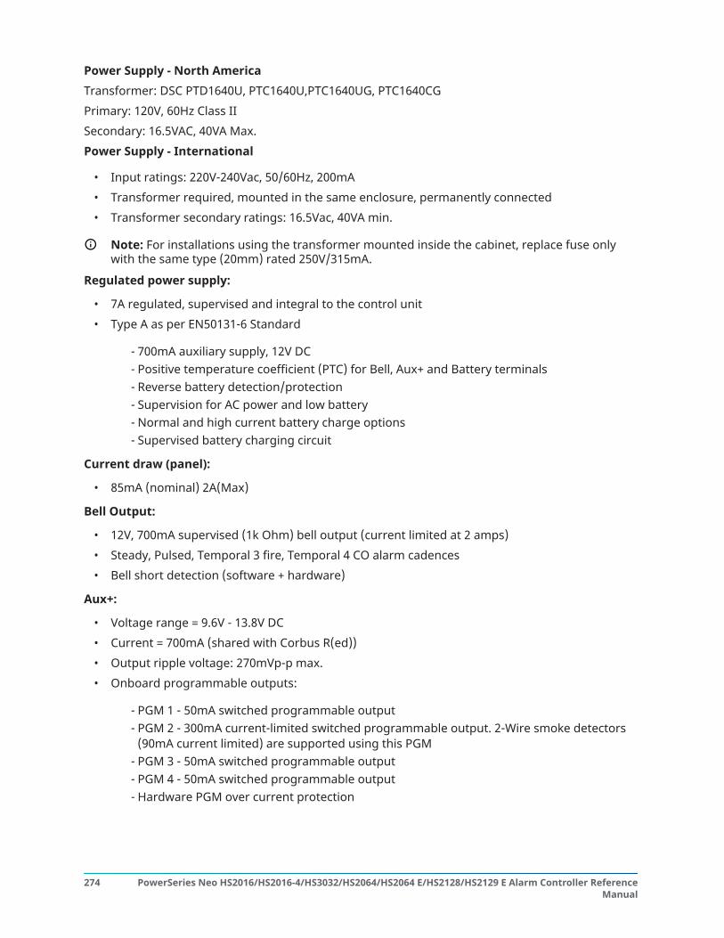
Power Supply - North AmericaTransformer: DSC PTD1640U, PTC1640U,PTC1640UG, PTC1640CGPrimary: 120V, 60Hz Class IISecondary: 16.5VAC, 40VA Max.Power Supply - International
• Input ratings: 220V-240Vac, 50/60Hz, 200mA• Transformer required, mounted in the same enclosure, permanently connected• Transformer secondary ratings: 16.5Vac, 40VA min.
Note: For installations using the transformer mounted inside the cabinet, replace fuse onlywith the same type (20mm) rated 250V/315mA.
Regulated power supply:
• 7A regulated, supervised and integral to the control unit• Type A as per EN50131-6 Standard
- 700mA auxiliary supply, 12V DC- Positive temperature coefficient (PTC) for Bell, Aux+ and Battery terminals- Reverse battery detection/protection- Supervision for AC power and low battery- Normal and high current battery charge options- Supervised battery charging circuit
Current draw (panel):
• 85mA (nominal) 2A(Max)
Bell Output:
• 12V, 700mA supervised (1k Ohm) bell output (current limited at 2 amps)• Steady, Pulsed, Temporal 3 fire, Temporal 4 CO alarm cadences• Bell short detection (software + hardware)
Aux+:
• Voltage range = 9.6V - 13.8V DC• Current = 700mA (shared with Corbus R(ed))• Output ripple voltage: 270mVp-p max.• Onboard programmable outputs:
- PGM 1 - 50mA switched programmable output- PGM 2 - 300mA current-limited switched programmable output. 2-Wire smoke detectors
(90mA current limited) are supported using this PGM- PGM 3 - 50mA switched programmable output- PGM 4 - 50mA switched programmable output- Hardware PGM over current protection
PowerSeries Neo HS2016/HS2016-4/HS3032/HS2064/HS2064 E/HS2128/HS2129 E Alarm Controller ReferenceManual
274

Battery
• 12V sealed lead acid, rechargeable• Battery capacity:
- hours (UL commercial burglary/residential burglary),- hours (EN50131),- hours (UL/ULC resi fire, ULC com burglary, ULC com fire monitoring - no bell load allowed)
INCERT [Belgium]
Note: For T 014 compliance (INCERT certification), only 14Ah (2x7Ah) batteries weretested and are accepted for INCERT certified systems.
• Maximum standby time: 24 hours (with 14Ah battery and Aux current limited to 470mA)• Recharging time to 80% 72 hours• Recharging rate: 240mA (12 hours max.), 480mA (24 hour backup)• Backup time: 24 hours (UL)• Battery lifespan: 3-5 years• Low battery trouble indication threshold 11.5VDC• Battery restore voltage 12.5V• Main board current draw (battery only):
- HS2016-4/32/64/128 (no alternate communicator) standby 85mA DC- HS2016-4/32/64/128, (including alternate communicator) standby 190mA DC- Transmit (alternate communicator module) 195mA DC
• Resettable fuses (PTC) used on circuit board• Supervision for loss of primary power source (AC fail), battery loss or battery low voltage
(battery trouble) with indication provided on the keypad• Internal clock locked to AC power frequency
Operating Environmental Conditions
• Temperature range: UL= 0°C to +49°C (32°F-120°F), EN= -10°C to 55°C (50°F-131°F)• Relative humidity: <93% non condensing
Alarm Transmitter Equipment (ATE) Specification
• Digital dialer integral to the main control board• Supports SIA and Contact ID• Complies with TS203 021-1, -2, -3 Telecom equipment requirements and EN50136-1-1,
EN50136-2-1, EN50136-2-3 ATS 2• Optional Dual IP/Cellular communicators (3G2080(R)E/ TL2803G(R)E/ TL280(R)E) can be
installed in the same enclosure and configured as primary or back-up, with AES 128-bitencryption
• Compliant with EN50136-1-1, EN50136-2-1 ATS2 requirements
System Supervision Features
275PowerSeries Neo HS2016/HS2016-4/HS3032/HS2064/HS2064 E/HS2128/HS2129 E Alarm Controller ReferenceManual

The PowerSeries Neo continuously monitors a number of possible trouble conditions and providesaudible and visual indication at the keypad. Trouble conditions include:
• AC power failure• Zone trouble• Fire trouble• Telephone line trouble• Communicator trouble• Low battery condition• RF jam• AUX power supply fault• Failure to communicate• Module fault (supervisory or tamper)
Additional Features
• 2-way wireless device support• Visual verification (images + audio)*• Proximity tag support• PGM scheduling• Quick arming• User, partition, module, zone and system labels• Soak test*• Programmable system loop response• Keypad and panel software versions viewable through keypad• Doorbell zone type• Low battery PGM type
*Feature not evaluated by UL/ULC.
Locating Detectors and Escape PlanAbout this task:The following information is for general guidance only and it is recommended that local fire codesand regulations be consulted when locating and installing smoke and CO alarms.Smoke DetectorsResearch has shown that all hostile fires in homes generate smoke to a greater or lesser extent.Experiments with typical fires in homes indicate that detectable quantities of smoke precededetectable levels of heat in most cases. Smoke alarms should be installed outside of each sleepingarea and on each storey of the home.It is recommended that additional smoke alarms beyond those required for minimum protectionbe installed. Additional areas that should be protected include: the basement; bedrooms, especiallywhere smokers sleep; dining rooms; furnace and utility rooms; and any hallways not protectedby the required units. On smooth ceilings, detectors may be spaced 9.1m (30 feet) apart as aguide. Other spacing may be required depending on ceiling height, air movement, the presence of
PowerSeries Neo HS2016/HS2016-4/HS3032/HS2064/HS2064 E/HS2128/HS2129 E Alarm Controller ReferenceManual
276

joists, uninsulated ceilings, etc. Consult National Fire Alarm Code NFPA 72, CAN/ULC-S553 or otherappropriate national standards for installation recommendations.
• Do not locate smoke detectors at the top of peaked or gabled ceilings; the dead air space inthese locations may prevent the unit from detecting smoke.
• Avoid areas with turbulent air flow, such as doorways, fans or windows. Rapid air movementaround the detector may prevent smoke from entering the unit.
• Do not locate detectors in areas of high humidity.• Do not locate detectors in areas where the temperature rises above 38ºC (100ºF) or falls below
5ºC (41ºF).• Smoke detectors should always be installed in USA in accordance with Chapter 29 of NFPA 72,
the National Fire Alarm Code.
Where required by applicable laws, codes, or standards for a specific type of occupancy, approvedsingle- and multiple-station smoke alarms shall be installed as follows:
1. In all sleeping rooms and guest rooms.2. Outside of each separate dwelling unit sleeping area, within 6.4 m (21 ft) of any door to a
sleeping room, the distance measured along a path of travel.3. On every level of a dwelling unit, including basements.4. On every level of a residential board and care occupancy (small facility), including basements
and excluding crawl spaces and unfinished attics.5. In the living area(s) of a guest suite.6. In the living area(s) of a residential board and care occupancy (small facility).
Figure 1Figure 2 Figure 3
Figure 3a
Figure 4
Fire Escape Planning
There is often very little time between the detection of a fire and the time it becomes deadly. It isthus very important that a family escape plan be developed and rehearsed.
1. Every family member should participate in developing the escape plan.
277PowerSeries Neo HS2016/HS2016-4/HS3032/HS2064/HS2064 E/HS2128/HS2129 E Alarm Controller ReferenceManual

2. Study the possible escape routes from each location within the house. Since many fires occurat night, special attention should be given to the escape routes from sleeping quarters.
3. Escape from a bedroom must be possible without opening the interior door.
ResultConsider the following when making your escape plans:
• Ensure all border doors and windows are easily opened. Ensure that they are not painted shut,and the locking mechanisms operate smoothly.
• If opening or using the exit is too difficult for children, the elderly or handicapped, plans forrescue should be developed. This includes making sure that those who are to perform therescue can promptly hear the fire warning signal.
• If the exit is above the ground level, an approved fire ladder or rope should be provided as wellas training in its use.
• Exits on the ground level should be kept clear. Be sure to remove snow from exterior patiodoors in winter; outdoor furniture or equipment should not block exits.
• Each person should know the predetermined assembly point where everyone can beaccounted for (e.g., across the street or at a neighbor's house). Once everyone is out of thebuilding, call the fire department.
• A good plan emphasizes quick escape. Do not attempt to fight the fire, and do not gatherbelongings as this can waste valuable time. Once outside, do not re-enter the house. Wait forthe fire department.
• Write the fire escape plan down and rehearse it frequently so that should an emergency arise,everyone will know what to do. Revise the plan as conditions change, such as the number ofpeople in the home, or if there are changes to the building’s construction.
• Make sure your fire warning system is operational by conducting weekly tests. If you areunsure about system operation, contact your installer.
• We recommend that you contact your local fire department and request further informationon fire safety and escape planning. If available, have your local fire prevention officer conductan in-house fire safety inspection.
Carbon Monoxide Detectors
Figure 5Carbon monoxide is colorless, odorless, tasteless, and very toxic, it also moves freely in the air. COdetectors can measure the concentration and sound a loud alarm before a potentially harmful levelis reached. The human body is most vulnerable to the effects of CO gas during sleeping hours;therefore, CO detectors should be located in or as near as possible to sleeping areas of the home.For maximum protection, a CO alarm should be located outside primary sleeping areas or on eachlevel of your home. Figure 5 indicates the suggested locations in the home.Do NOT place the CO alarm in the following areas:
• Where the temperature may drop below -10ºC or exceed 40ºC
PowerSeries Neo HS2016/HS2016-4/HS3032/HS2064/HS2064 E/HS2128/HS2129 E Alarm Controller ReferenceManual
278

• Near paint thinner fumes• Within 5 feet (1.5m) of open flame appliances such as furnaces, stoves and fireplaces• In exhaust streams from gas engines, vents, flues or chimneys• In close proximity to an automobile exhaust pipe; this will damage the detector
PLEASE REFER TO THE CO DETECTOR INSTALLATION AND OPERATING INSTRUCTION SHEET FORSAFETY INSTRUCTIONS AND EMERGENCY INFORMATION.
Limited WarrantyDigital Security Controls warrants the original purchaser that for a period of twelve months fromthe date of purchase, the product shall be free of defects in materials and workmanship undernormal use. During the warranty period, Digital Security Controls shall, at its option, repair orreplace any defective product upon return of the product to its factory, at no charge for labour andmaterials. Any replacement and/or repaired parts are warranted for the remainder of the originalwarranty or ninety (90) days, whichever is longer. The original purchaser must promptly notifyDigital Security Controls in writing that there is defect in material or workmanship, such writtennotice to be received in all events prior to expiration of the warranty period. There is absolutely nowarranty on software and all software products are sold as a user license under the terms of thesoftware license agreement included with the product. The Customer assumes all responsibility forthe proper selection, installation, operation and maintenance of any products purchased from DSC.Custom products are only warranted to the extent that they do not function upon delivery. In suchcases, DSC can replace or credit at its option.International WarrantyThe warranty for international customers is the same as for any customer within Canada and theUnited States, with the exception that Digital Security Controls shall not be responsible for anycustoms fees, taxes, or VAT that may be due.Warranty ProcedureTo obtain service under this warranty, please return the item(s) in question to the point ofpurchase. All authorized distributors and dealers have a warranty program. Anyone returninggoods to Digital Security Controls must first obtain an authorization number. Digital SecurityControls will not accept any shipment whatsoever for which prior authorization has not beenobtained.Conditions to Void WarrantyThis warranty applies only to defects in parts and workmanship relating to normal use. It does notcover:
• damage incurred in shipping or handling;• damage caused by disaster such as fire, flood, wind, earthquake or lightning;• damage due to causes beyond the control of Digital Security Controls such as excessive
voltage, mechanical shock or water damage;• damage caused by unauthorized attachment, alterations, modifications or foreign objects;• damage caused by peripherals (unless such peripherals were supplied by DSC.);• defects caused by failure to provide a suitable installation environment for the products;• damage caused by use of the products for purposes other than those for which it was
designed;• damage from improper maintenance;
279PowerSeries Neo HS2016/HS2016-4/HS3032/HS2064/HS2064 E/HS2128/HS2129 E Alarm Controller ReferenceManual

• damage arising out of any other abuse, mishandling or improper application of the products.
Items Not Covered by WarrantyIn addition to the items which void the Warranty, the following items shall not be covered byWarranty: (i) freight cost to the repair centre; (ii) products which are not identified with DSC'sproduct label and lot number or serial number; (iii) products disassembled or repaired in such amanner as to adversely affect performance or prevent adequate inspection or testing to verify anywarranty claim. Access cards or tags returned for replacement under warranty will be credited orreplaced at DSC's option. Products not covered by this warranty, or otherwise out of warranty dueto age, misuse, or damage shall be evaluated, and a repair estimate shall be provided. No repairwork will be performed until a valid purchase order is received from the Customer and a ReturnMerchandise Authorization number (RMA) is issued by DSC's Customer Service.Digital Security Controls Ltd.’s liability for failure to repair the product under this warranty after areasonable number of attempts will be limited to a replacement of the product, as the exclusiveremedy for breach of warranty. Under no circumstances shall Digital Security Controls be liablefor any special, incidental, or consequential damages based upon breach of warranty, breach ofcontract, negligence, strict liability, or any other legal theory. Such damages include, but are notlimited to, loss of profits, loss of the product or any associated equipment, cost of capital, costof substitute or replacement equipment, facilities or services, down time, purchaser’s time, theclaims of third parties, including customers, and injury to property. The laws of some jurisdictionslimit or do not allow the disclaimer of consequential damages. If the laws of such a jurisdictionapply to any claim by or against DSC, the limitations and disclaimers contained here shall be to thegreatest extent permitted by law. Some states do not allow the exclusion or limitation of incidentalor consequential damages, so that the above may not apply to you.Disclaimer of WarrantiesThis warranty contains the entire warranty and shall be in lieu of any and all other warranties,whether expressed or implied (including all implied warranties of merchantability or fitness for aparticular purpose) and of all other obligations or liabilities on the part of Digital Security Controls.Digital Security Controls neither assumes responsibility for, nor authorizes any other personpurporting to act on its behalf to modify or to change this warranty, nor to assume for it any otherwarranty or liability concerning this product. This disclaimer of warranties and limited warranty aregoverned by the laws of the province of Ontario, Canada.
WARNING: Digital Security Controls recommends that the entire system be completely testedon a regular basis. However, despite frequent testing, and due to, but not limited to, criminaltampering or electrical disruption, it is possible for this product to fail to perform as expected.
Out of Warranty RepairsDigital Security Controls will at its option repair or replace out-of-warranty products which arereturned to its factory according to the following conditions. Anyone returning goods to DigitalSecurity Controls must first obtain an authorization number. Digital Security Controls will not acceptany shipment whatsoever for which prior authorization has not been obtained.Products which Digital Security Controls determines to be repairable will be repaired and returned.A set fee which Digital Security Controls has predetermined and which may be revised from timeto time, will be charged for each unit repaired. Products which Digital Security Controls determinesnot to be repairable will be replaced by the nearest equivalent product available at that time. Thecurrent market price of the replacement product will be charged for each replacement unit.WARNING - READ CAREFULLY - Note to InstallersThis warning contains vital information. As the only individual in contact with system users, it isyour responsibility to bring each item in this warning to the attention of the users of this system.System Failures
PowerSeries Neo HS2016/HS2016-4/HS3032/HS2064/HS2064 E/HS2128/HS2129 E Alarm Controller ReferenceManual
280

This system has been carefully designed to be as effective as possible. There are circumstances,however, involving fire, burglary, or other types of emergencies where it may not provideprotection. Any alarm system of any type may be compromised deliberately or may fail to operateas expected for a variety of reasons. Some but not all of these reasons may be:Inadequate InstallationA security system must be installed properly in order to provide adequate protection. Everyinstallation should be evaluated by a security professional to ensure that all access points and areasare covered. Locks and latches on windows and doors must be secure and operate as intended.Windows, doors, walls, ceilings and other building materials must be of sufficient strength andconstruction to provide the level of protection expected. A reevaluation must be done duringand after any construction activity. An evaluation by the fire and/or police department is highlyrecommended if this service is available.Criminal KnowledgeThis system contains security features which were known to be effective at the time ofmanufacture. It is possible for persons with criminal intent to develop techniques which reduce theeffectiveness of these features. It is important that a security system be reviewed periodically toensure that its features remain effective and that it be updated or replaced if it is found that it doesnot provide the protection expected.Access by IntrudersIntruders may enter through an unprotected access point, circumvent a sensing device, evadedetection by moving through an area of insufficient coverage, disconnect a warning device, orinterfere with or prevent the proper operation of the system.Power FailureControl units, intrusion detectors, smoke detectors and many other security devices require anadequate power supply for proper operation. If a device operates from batteries, it is possible forthe batteries to fail. Even if the batteries have not failed, they must be charged, in good conditionand installed correctly. If a device operates only by AC power, any interruption, however brief, willrender that device inoperative while it does not have power. Power interruptions of any lengthare often accompanied by voltage fluctuations which may damage electronic equipment such as asecurity system. After a power interruption has occurred, immediately conduct a complete systemtest to ensure that the system operates as intended.Failure of Replaceable BatteriesThis system’s wireless transmitters have been designed to provide several years of battery lifeunder normal conditions. The expected battery life is a function of the device environment,usage and type. Ambient conditions such as high humidity, high or low temperatures, or largetemperature fluctuations may reduce the expected battery life. While each transmitting device hasa low battery monitor which identifies when the batteries need to be replaced, this monitor may failto operate as expected. Regular testing and maintenance will keep the system in good operatingcondition.Compromise of Radio Frequency (Wireless) DevicesSignals may not reach the receiver under all circumstances which could include metal objectsplaced on or near the radio path or deliberate jamming or other inadvertent radio signalinterference.System UsersA user may not be able to operate a panic or emergency switch possibly due to permanent ortemporary physical disability, inability to reach the device in time, or unfamiliarity with the correctoperation. It is important that all system users be trained in the correct operation of the alarmsystem and that they know how to respond when the system indicates an alarm.Smoke Detectors
281PowerSeries Neo HS2016/HS2016-4/HS3032/HS2064/HS2064 E/HS2128/HS2129 E Alarm Controller ReferenceManual

Smoke detectors that are a part of this system may not properly alert occupants of a fire for anumber of reasons, some of which follow. The smoke detectors may have been improperly installedor positioned. Smoke may not be able to reach the smoke detectors, such as when the fire is ina chimney, walls or roofs, or on the other side of closed doors. Smoke detectors may not detectsmoke from fires on another level of the residence or building.Every fire is different in the amount of smoke produced and the rate of burning. Smoke detectorscannot sense all types of fires equally well. Smoke detectors may not provide timely warning offires caused by carelessness or safety hazards such as smoking in bed, violent explosions, escapinggas, improper storage of flammable materials, overloaded electrical circuits, children playing withmatches or arson.Even if the smoke detector operates as intended, there may be circumstances when there isinsufficient warning to allow all occupants to escape in time to avoid injury or death.Motion DetectorsMotion detectors can only detect motion within the designated areas as shown in their respectiveinstallation instructions. They cannot discriminate between intruders and intended occupants.Motion detectors do not provide volumetric area protection. They have multiple beams of detectionand motion can only be detected in unobstructed areas covered by these beams. They cannotdetect motion which occurs behind walls, ceilings, floor, closed doors, glass partitions, glass doorsor windows. Any type of tampering whether intentional or unintentional such as masking, painting,or spraying of any material on the lenses, mirrors, windows or any other part of the detectionsystem will impair its proper operation.Passive infrared motion detectors operate by sensing changes in temperature. However theireffectiveness can be reduced when the ambient temperature rises near or above body temperatureor if there are intentional or unintentional sources of heat in or near the detection area. Some ofthese heat sources could be heaters, radiators, stoves, barbeques, fireplaces, sunlight, steam vents,lighting and so on.Warning DevicesWarning devices such as sirens, bells, horns, or strobes may not warn people or waken someonesleeping if there is an intervening wall or door. If warning devices are located on a different levelof the residence or premise, then it is less likely that the occupants will be alerted or awakened.Audible warning devices may be interfered with by other noise sources such as stereos, radios,televisions, air conditioners or other appliances, or passing traffic. Audible warning devices,however loud, may not be heard by a hearing-impaired person.Telephone LinesIf telephone lines are used to transmit alarms, they may be out of service or busy for certainperiods of time. Also an intruder may cut the telephone line or defeat its operation by moresophisticated means which may be difficult to detect.Insufficient TimeThere may be circumstances when the system will operate as intended, yet the occupants willnot be protected from the emergency due to their inability to respond to the warnings in a timelymanner. If the system is monitored, the response may not occur in time to protect the occupants ortheir belongings.Component FailureAlthough every effort has been made to make this system as reliable as possible, the system mayfail to function as intended due to the failure of a component.Inadequate TestingMost problems that would prevent an alarm system from operating as intended can be found byregular testing and maintenance. The complete system should be tested weekly and immediatelyafter a break-in, an attempted break-in, a fire, a storm, an earthquake, an accident, or any kind of
PowerSeries Neo HS2016/HS2016-4/HS3032/HS2064/HS2064 E/HS2128/HS2129 E Alarm Controller ReferenceManual
282

construction activity inside or outside the premises. The testing should include all sensing devices,keypads, consoles, alarm indicating devices and any other operational devices that are part of thesystem.Security and InsuranceRegardless of its capabilities, an alarm system is not a substitute for property or life insurance.An alarm system also is not a substitute for property owners, renters, or other occupants to actprudently to prevent or minimize the harmful effects of an emergency situation.
Software Product License (EULA)The SOFTWARE PRODUCT is protected by copyright laws and international copyright treaties, aswell as other intellectual property laws and treaties. The SOFTWARE PRODUCT is licensed, not sold.1. GRANT OF LICENSE This EULA grants You the following rights:(a) Software Installation and Use - For each license You acquire, You may have only one copy of theSOFTWARE PRODUCT installed.(b) Storage/Network Use - The SOFTWARE PRODUCT may not be installed, accessed, displayed, run,shared or used concurrently on or from different computers, including a workstation, terminal orother digital electronic device (“Device”). In other words, if You have several workstations, You willhave to acquire a license for each workstation where the SOFTWARE will be used.(c) Backup Copy - You may make back-up copies of the SOFTWARE PRODUCT, but You may onlyhave one copy per license installed at any given time. You may use the back-up copy solely forarchival purposes. Except as expressly provided in this EULA, You may not otherwise make copies ofthe SOFTWARE PRODUCT, including the printed materials accompanying the SOFTWARE.2. DESCRIPTION OF OTHER RIGHTS AND LIMITATIONS(a) Limitations on Reverse Engineering, Decompilation and Disassembly - You may not reverseengineer, decompile, or disassemble the SOFTWARE PRODUCT, except and only to the extent thatsuch activity is expressly permitted by applicable law notwithstanding this limitation. You may notmake any changes or modifications to the Software, without the written permission of an officerof DSC. You may not remove any proprietary notices, marks or labels from the Software Product.You shall institute reasonable measures to ensure compliance with the terms and conditions of thisEULA.(b) Separation of Components - The SOFTWARE PRODUCT is licensed as a single product. Itscomponent parts may not be separated for use on more than one HARDWARE unit.(c) Single INTEGRATED PRODUCT - If You acquired this SOFTWARE with HARDWARE, then theSOFTWARE PRODUCT is licensed with the HARDWARE as a single integrated product. In this case,the SOFTWARE PRODUCT may only be used with the HARDWARE as set forth in this EULA.(d) Rental - You may not rent, lease or lend the SOFTWARE PRODUCT. You may not make it availableto others or post it on a server or web site.(e) Software Product Transfer - You may transfer all of Your rights under this EULA only as partof a permanent sale or transfer of the HARDWARE, provided You retain no copies, You transferall of the SOFTWARE PRODUCT (including all component parts, the media and printed materials,any upgrades and this EULA), and provided the recipient agrees to the terms of this EULA. Ifthe SOFTWARE PRODUCT is an upgrade, any transfer must also include all prior versions of theSOFTWARE PRODUCT.(f) Termination - Without prejudice to any other rights, DSC may terminate this EULA if You fail tocomply with the terms and conditions of this EULA. In such event, You must destroy all copies of theSOFTWARE PRODUCT and all of its component parts.
283PowerSeries Neo HS2016/HS2016-4/HS3032/HS2064/HS2064 E/HS2128/HS2129 E Alarm Controller ReferenceManual

(g) Trademarks - This EULA does not grant You any rights in connection with any trademarks orservice marks of DSC or its suppliers.3. COPYRIGHT - All title and intellectual property rights in and to the SOFTWARE PRODUCT(including but not limited to any images, photographs, and text incorporated into the SOFTWAREPRODUCT), the accompanying printed materials, and any copies of the SOFTWARE PRODUCT,are owned by DSC or its suppliers. You may not copy the printed materials accompanying theSOFTWARE PRODUCT. All title and intellectual property rights in and to the content which may beaccessed through use of the SOFTWARE PRODUCT are the property of the respective content ownerand may be protected by applicable copyright or other intellectual property laws and treaties. ThisEULA grants You no rights to use such content. All rights not expressly granted under this EULA arereserved by DSC and its suppliers.4. EXPORT RESTRICTIONS - You agree that You will not export or re-export the SOFTWAREPRODUCT to any country, person, or entity subject to Canadian export restrictions.5. CHOICE OF LAW - This Software License Agreement is governed by the laws of the Province ofOntario, Canada.6. ARBITRATION - All disputes arising in connection with this Agreement shall be determined byfinal and binding arbitration in accordance with the Arbitration Act, and the parties agree to bebound by the arbitrator’s decision. The place of arbitration shall be Toronto, Canada, and theinstallation manual of the arbitration shall be English.7. LIMITED WARRANTY(a) NO WARRANTY - DSC PROVIDES THE SOFTWARE “AS IS” WITHOUT WARRANTY. DSC DOES NOTWARRANT THAT THE SOFTWARE WILL MEET YOUR REQUIREMENTS OR THAT OPERATION OF THESOFTWARE WILL BE UNINTERRUPTED OR ERROR-FREE.(b) CHANGES IN OPERATING ENVIRONMENT - DSC shall not be responsible for problems caused bychanges in the operating characteristics of the HARDWARE, or for problems in the interaction of theSOFTWARE PRODUCT with non-DSC-SOFTWARE or HARDWARE PRODUCTS.(c) LIMITATION OF LIABILITY; WARRANTY REFLECTS ALLOCATION OF RISK - IN ANY EVENT, IF ANYSTATUTE IMPLIES WARRANTIES OR CONDITIONS NOT STATED IN THIS LICENSE AGREEMENT, DSC’SENTIRE LIABILITY UNDER ANY PROVISION OF THIS LICENSE AGREEMENT SHALL BE LIMITED TOTHE GREATER OF THE AMOUNT ACTUALLY PAID BY YOU TO LICENSE THE SOFTWARE PRODUCTAND FIVE CANADIAN DOLLARS (CAD$5.00). BECAUSE SOME JURISDICTIONS DO NOT ALLOW THEEXCLUSION OR LIMITATION OF LIABILITY FOR CONSEQUENTIAL OR INCIDENTAL DAMAGES, THEABOVE LIMITATION MAY NOT APPLY TO YOU.(d) DISCLAIMER OF WARRANTIES - THIS WARRANTY CONTAINS THE ENTIRE WARRANTY AND SHALLBE IN LIEU OF ANY AND ALL OTHER WARRANTIES, WHETHER EXPRESSED OR IMPLIED (INCLUDINGALL IMPLIED WARRANTIES OF MERCHANTABILITY OR FITNESS FOR A PARTICULAR PURPOSE)AND OF ALL OTHER OBLIGATIONS OR LIABILITIES ON THE PART OF DSC. DSC MAKES NO OTHERWARRANTIES. DSC NEITHER ASSUMES NOR AUTHORIZES ANY OTHER PERSON PURPORTING TO ACTON ITS BEHALF TO MODIFY OR TO CHANGE THIS WARRANTY, NOR TO ASSUME FOR IT ANY OTHERWARRANTY OR LIABILITY CONCERNING THIS SOFTWARE PRODUCT.(e) EXCLUSIVE REMEDY AND LIMITATION OF WARRANTY - UNDER NO CIRCUMSTANCES SHALLDSC BE LIABLE FOR ANY SPECIAL, INCIDENTAL, CONSEQUENTIAL OR INDIRECT DAMAGES BASEDUPON BREACH OF WARRANTY, BREACH OF CONTRACT, NEGLIGENCE, STRICT LIABILITY, OR ANYOTHER LEGAL THEORY. SUCH DAMAGES INCLUDE, BUT ARE NOT LIMITED TO, LOSS OF PROFITS,LOSS OF THE SOFTWARE PRODUCT OR ANY ASSOCIATED EQUIPMENT, COST OF CAPITAL, COST OFSUBSTITUTE OR REPLACEMENT EQUIPMENT, FACILITIES OR SERVICES, DOWN TIME, PURCHASERSTIME, THE CLAIMS OF THIRD PARTIES, INCLUDING CUSTOMERS, AND INJURY TO PROPERTY.