powerpoint presentation · pdf filepoles or fixtures. contact pemco for details. ... voltage:...
TRANSCRIPT

WOO/LUC-064-12.03/00.00 SR 64 (Mechanic St.) over the Maumee River Bridge Replacement Project (Aesthetic Details)

PROJECT TEAM:
ODOT Brad Noll – PM Dave Geckle – PM The Mannik & Smith Group Chris Homan – PM Travis Rhoades – Lead Bridge Engineer Chris Beaulieu – Lead Roadway Engineer Pat Etchie – Planner Ray Luk – Transportation Group Manager

AGENDA
• Project Timeline • City Resolution • Project Schematic • Bridge Plan & Profile • Bike Path Grading • Integrated Concepts • Aesthetic Details (Open Discussion) • Landscaping Ideas?

PROJECT TIMELINE
Milestone Date
Begin Project 2/1/2013
City of Waterville Historic Commission/Society Meeting 11/6/2013 doc pptx
City Resolution 04-14 2/24/2014 doc
Public Meeting (Waterville Primary School) 3/27/2014 doc
Alternatives Evaluation Report (AER) 8/24/15 doc
Stage 1 Plans 2/5/2016
Stage 2 Plans (Current Stage) 11/10/2016 doc
Stage 3 Plans TBD
Final Plans 8/14/2017
Begin Construction 4/1/2018

CITY RESOLUTION 04-14
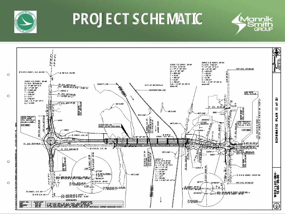
PROJECT SCHEMATIC

BRIDGE SITE PLAN

BRIDGE SITE PLAN
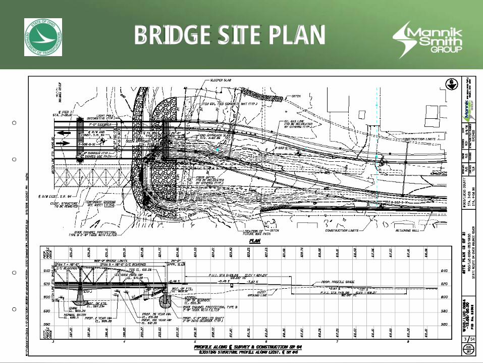
BRIDGE SITE PLAN

BIKE PATH GRADING

INTEGRATED CONCEPTS

INTEGRATED CONCEPTS

INTEGRATED CONCEPTS

AESTHETIC DETAILS
Discussion Item Details
Arched Spans Color (*)
Observation Platforms Shape (3 examples)
Decorative Outer Metal Railings Shape (option 5 preferred for interior bike rail)
Pier Cut Stone Color (*), depth
Lighting / Signal Poles City Std. (**)
Landscaping Details Ideas - trees, etc. (***)
(*) Color – any city tones or preferences? (**) Use “W” or “W” with “Historic District” - Map.pdf (***) City prefers trees per Waterville Tree Commission Master Street Trees 2016
Aesthetic Package.pdf

~tRY1LLE, ON, ~t->onthebanlzsofhi.story fQ
City of Waterville
25 North Second Street
Waterville, Ohio 43566-1491
0 Municipal Administrator 878-8100
~ Director of Finance & Administration 878-8100
0 Public Works Direclor 878-8108
AREA CODE 419
});;n4- () 1 ~
LETTER OF TRANSMITIAL
TO: Mr. Todd M . Audet, P.E.
Deputy Director District Two
Ohio Dept. of Transportation
317 East Poe Rd .
Bowling Green, Ohio 43402
DATE: 2/27/2014
ATIENTION: Mr. Todd M. Audet
RE: Resolution 04-14: A Resolution Adopting Recommendations to the Ohio Department of Transportation Regarding the Replacement of the Waterville Bridge (St. Rt. 64) Over the Maumee River
WE ARE SENDING YOU: ~ Herewith 0 Under separate cover via ______ the following items:
COPIES DATE
1 02/24/2014
THESE ARE TRANSMITIED: D For approval
~ For your use
0 As requested
DESCRIPTION
City of Waterville Resolution 04-14, Certified Copy- A Resolution Adopting Recommendations to the Ohio Department of Transportation Regarding the Replacement of the Waterville Bridge (St. Rt. 64) Over the Maumee River
0 For review and comment
D For your execution
~ For your information
Ul\0 ., ?n u .., '
I tdllll"•.,
<onrl Fnoimeri!tt.:
~ For your files
D To be returned
REMARKS: Resolution of recommendations adopted by of the City of Waterville Council and supported by city's Historic District Commission ond Planning Commission.
COPY TO : Mr. Jerry Wray. Director. ODOT
SIGNED: ~=-~-~~---Dale D. Knepper, Clerk;clc~~{-------
0606 If enclosures arc not as noted, kind ly notify us at once.
RECORD OF RESOLUTIONS
Resolution No. 04-14 Passed
A RESOLUTION ADOPTING RECOMMENDATIONS TO THE OIDO DEPARTMENT OF TRANSPORTATION REGARDING TilE REPLACEMENT OF TilE WATERVILLE BRIDGE (STATE ROUTE 64) OVER THE MAUMEE RIVER
WHEREAS, the Ohio Department of Transportation (ODOT) is currently undertaking a study of
the replacement of the Waterville Bridge (State Route 64) over the Maumee River through its consultant
The Mannik and Smith Group, Inc.; and
WHEREAS, the City understands that the consultant is examining three alternative alignments
for a new bridge; and
WHEREAS, d1e City's Historic District Commission and Planning Commission have made
certain recommendations regarding the replacement of the bridge for City Council's consideration; and
WHEREAS, the Waterville Bridge is a vital highway link for travel and commerce in the
immediate Waterville area, the Anthony Wayne Local School District, Lucas and Wood Counties and the
Toledo metropolitan area in general; and
WHEREAS, ODOT is planning to conduct a Public Meeting during March 2014 concerning the
replacement of the bridge; and
WIIEREAS, the Council would like to make certain recommendations to ODOT regarding the
replacement of the Waterville Bridge.
NOW, THEREFORE, BE JT RESOLVED by the Council of the City of Waterville, Lucas County,
Ohio that:
SECTION 1. The Council hereby adopts the following recommendations to the Ohio
Department of Transportation regarding the replncement of the Waterville Bridge:
I. A new bridge location direcdy adjacent to the upstream side of the existing bridge is strongly
preferred.
2. A Shared Use Path should be located on the downstream side of the new bridge with a ramp
connection under the bridge to Memorial Park and the site of the fonner Waterville School. A
sidewalk could be included on the upstream side of the new bridge.
3. Two observation platforms should be placed along the downstream shared use path and two
additional observation platforms should be placed along the upstream sidewalk, if the sidewalk is
included.
4. Decorative outer metal railings (newer bridges in Findlay and Napoleon are good examples) and a
low decorative concrete barrier (similar to the O'Shaughnessy Reservoir-Scioto River bridge)
separating motorized vehicle traffic from the path and the sidewalk that maximiZe visibility of the
river for motorists should be incorporated into the design. . .. ,.. ... 5. The bridge piers should have the appearance of cut stone.
6. No matter what material is used, the bridge spans ~hould be arched.
7. The new bridge should include roadway, shared use path and sidewalk lighting with brackets for
flags and banners to match the new street lighting in downtown Waterville. Energy efficient
decorative lighting should also be included in the bridge design.


AA-6(2016) Lighting Products,Inc. 150 Pemco Way-Wilmington, DE 19804 Phone 302.892.9000 Fax 302.892.9005 www.pemcolighting.com [email protected]
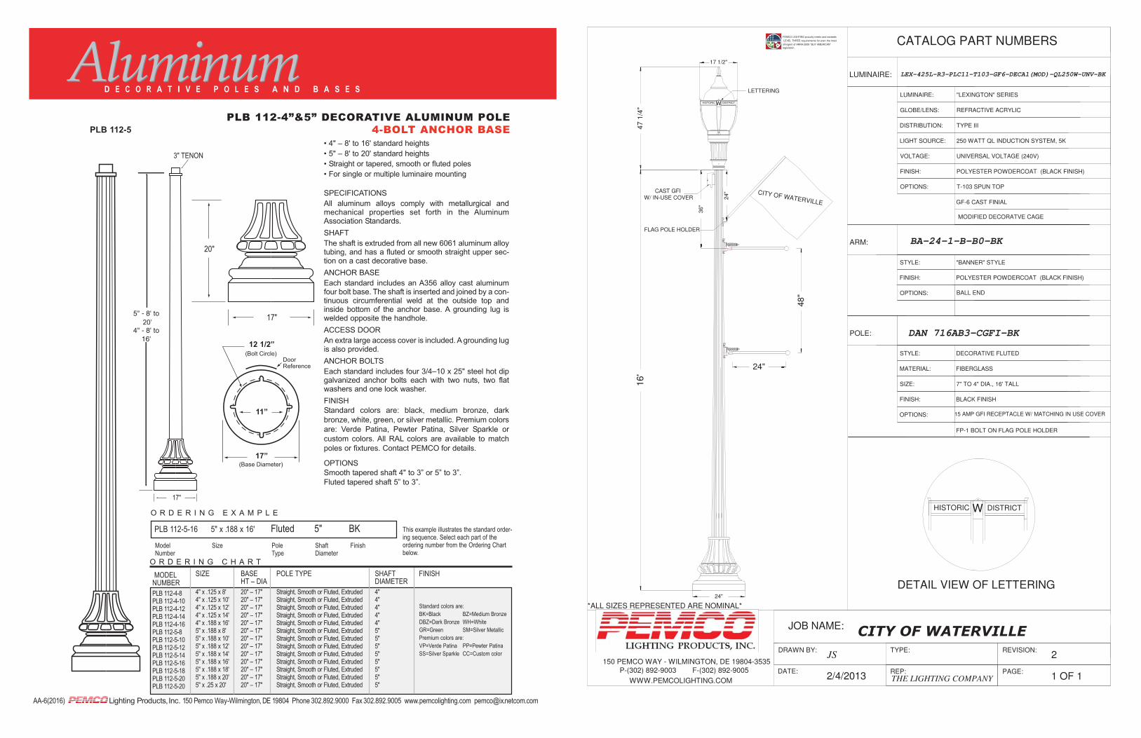
• 4" – 8' to 16' standard heights
• 5" – 8' to 20' standard heights
• Straight or tapered, smooth or fluted poles
• For single or multiple luminaire mounting
SPECIFICATIONS
All aluminum alloys comply with metallurgical andmechanical properties set forth in the AluminumAssociation Standards.
SHAFT
The shaft is extruded from all new 6061 aluminum alloytubing, and has a fluted or smooth straight upper sec-tion on a cast decorative base.
ANCHOR BASE
Each standard includes an A356 alloy cast aluminumfour bolt base. The shaft is inserted and joined by a con-tinuous circumferential weld at the outside top andinside bottom of the anchor base. A grounding lug iswelded opposite the handhole.
ACCESS DOOR
An extra large access cover is included. A grounding lugis also provided.
ANCHOR BOLTS
Each standard includes four 3/4–10 x 25" steel hot dipgalvanized anchor bolts each with two nuts, two flatwashers and one lock washer.
FINISH
Standard colors are: black, medium bronze, dark
bronze, white, green, or silver metallic. Premium colors
are: Verde Patina, Pewter Patina, Silver Sparkle or
custom colors. All RAL colors are available to match
poles or fixtures. Contact PEMCO for details.
OPTIONS
Smooth tapered shaft 4" to 3” or 5” to 3”.
Fluted tapered shaft 5” to 3”.
PLB 112-5
O R D E R I N G E X A M P L E
PLB 112-5-16 5" x .188 x 16' Fluted 5" BKModel Size Pole Shaft FinishNumber Type Diameter
This example illustrates the standard order-ing sequence. Select each part of theordering number from the Ordering Chartbelow.
SHAFTDIAMETER4"4"4"4"4"5"5"5"5"5"5"5"5"
FINISHMODELNUMBERPLB 112-4-8PLB 112-4-10PLB 112-4-12PLB 112-4-14PLB 112-4-16PLB 112-5-8PLB 112-5-10PLB 112-5-12PLB 112-5-14PLB 112-5-16PLB 112-5-18PLB 112-5-20PLB 112-5-20
O R D E R I N G C H A R T
20"
17"
17"
5" - 8' to20'
4" - 8' to16'
3" TENON
PLB 112-4”&5” DECORATIVE ALUMINUM POLE4-BOLT ANCHOR BASE
12 1/2”
17”
11”
SIZE
4" x .125 x 8'4" x .125 x 10'4" x .125 x 12'4" x .125 x 14'4" x .188 x 16'5" x .188 x 8'5" x .188 x 10'5" x .188 x 12'5" x .188 x 14'5" x .188 x 16'5" x .188 x 18'5" x .188 x 20'5" x .25 x 20'
BASE HT – DIA20" – 17"20" – 17"20" – 17"20" – 17"20" – 17"20" – 17"20" – 17"20" – 17"20" – 17"20" – 17"20" – 17"20" – 17"20" – 17"
POLE TYPE
Straight, Smooth or Fluted, ExtrudedStraight, Smooth or Fluted, ExtrudedStraight, Smooth or Fluted, ExtrudedStraight, Smooth or Fluted, ExtrudedStraight, Smooth or Fluted, ExtrudedStraight, Smooth or Fluted, ExtrudedStraight, Smooth or Fluted, ExtrudedStraight, Smooth or Fluted, ExtrudedStraight, Smooth or Fluted, ExtrudedStraight, Smooth or Fluted, ExtrudedStraight, Smooth or Fluted, ExtrudedStraight, Smooth or Fluted, ExtrudedStraight, Smooth or Fluted, Extruded
Standard colors are: BK=Black BZ=Medium BronzeDBZ=Dark Bronze WH=WhiteGR=Green SM=Silver MetallicPremium colors are: VP=Verde Patina PP=Pewter PatinaSS=Silver Sparkle CC=Custom color
20’
1 OF 1
*ALL SIZES REPRESENTED ARE NOMINAL*
REP:
JOB NAME:
150 PEMCO WAY - WILMINGTON, DE 19804-3535P-(302) 892-9003 F-(302) 892-9005
WWW.PEMCOLIGHTING.COM
DRAWN BY:JS
DATE:2/4/2013
TYPE: REVISION: 2
PAGE:THE LIGHTING COMPANY
CATALOG PART NUMBERS
LUMINAIRE: LEX-425L-R3-PLC11-T103-GF6-DECA1(MOD)-QL250W-UNV-BK
LUMINAIRE: "LEXINGTON" SERIES
TYPE IIIDISTRIBUTION:
250 WATT QL INDUCTION SYSTEM, 5KLIGHT SOURCE:
REFRACTIVE ACRYLICGLOBE/LENS:
UNIVERSAL VOLTAGE (240V)VOLTAGE:
POLYESTER POWDERCOAT (BLACK FINISH)FINISH:
OPTIONS:
ARM: BA-24-1-B-B0-BK
STYLE: "BANNER" STYLE
OPTIONS:
FINISH: POLYESTER POWDERCOAT (BLACK FINISH)
T-103 SPUN TOP
POLE:
STYLE: DECORATIVE FLUTED
SIZE: 7" TO 4" DIA., 16' TALL
FINISH: BLACK FINISH
OPTIONS:
MATERIAL: FIBERGLASS
BALL END
DAN 716AB3-CGFI-BK
GF-6 CAST FINIAL
15 AMP GFI RECEPTACLE W/ MATCHING IN USE COVER
FP-1 BOLT ON FLAG POLE HOLDER
PEMCO LIGHTING proudly meets and exceeds
LEVEL THREE requirements for even the most
stringent of ARRA-2009 "BUY AMERICAN"legislation.
MODIFIED DECORATVE CAGE
24"
16'
FLAG POLE HOLDER
W
17 1/2"
48"
24"
LETTERING
47 1
/4"
CAST GFIW/ IN-USE COVER
CITY OF WATERVILLE
24"
36"
HISTORIC DISTRICT
WHISTORIC DISTRICT
DETAIL VIEW OF LETTERING

~FINIAL
A ~METAL ROOF
f /, 7 ~~~~~Jt ~~ ~~~oWoy E'6'U~~rROUND E!i.iiliJ Wl:liiill II l·iiiiiliiil-.r.:l\~! l:i'.iliia;;.' ..Qoill l ~rt1 BbU l,iik; -JilFIJr METAL CAGE
~~ lii/L~ ~~"'':!£~._ GLOBE
1 rnr 1 rnr~ POD ~ ~ !!f ~SPECIAL SUP FITIER TO ATIACH TO ~ ~ ~ POLE OR APPROVED EQUAL ATIACHMENT
]]i E~IIIDI III[§gffiJI v r-- v
Lo
TWIN LUMINAIRE
SPECIFICATIONS:
DETAIL
FIXTURE : HADCO, "B" POD STYLE, WIDE GLOBE OR PEMCO LEXINGTON
1. ACRYUC GLOBE, METAL ROOF, METAL CAGE, METAL POD, AND FINIAL TOP PIECE. SPECIAL LETTERING ON CAGE BAND. BLACK FINISH.
2 . 150 WATI METAL HAUDE UGHT SOURCE, 120 VOLT. 3. HADCO NO. R34LCBAATNG150HE
PEMCO NO. LEX-425L-R3-PLC1-T1 03-GF6-DECAI (MODIFIED )-150MH-t.4T -BK
CROSS ARM
1. CAST / EXTRUDED ALUMINUM SECTIONS WELDED TOGETHER AND HEAT TREATED TO T6 TEMPER.
2. PROVIDE RIGID MOUNTING SYSTEM TO PROHIBIT ROTATING IN THE WIND.
3. STAINLESS STEEL SET SCREWS 4. POLYESTER POWDER COATING - BLACK FINISH. 5. VALMONT: LANCASTER SERIES PTA-LC3 UNION METAL; STYLE 1075
<t_ MAST ARM A (INDEX)
CLOCKWISE ORIENTATION ANGLES (SEE TABLE VALUES)
~ <D I MAST ARM A 0::
til ORIENTATION ...... tJ ANGLE UJ 0 0::
;_).~ 0
::IE
&
NOTES · ALL ANGLES MEASURED CLOCKWISE
· BASE PLATE IS ORIENTED SQUARE TO MAST ARM A
1 03676 LighlPoleOetoils
VIDEO w i ADJUST HEI CAMERA RIGID MOUNT AS NEEDED SIGNAL HEADS
(TYPICAL) R POLE AND ARM-FLUTED ~
.... = RADIAL BEND ~· ..,____ \ ' IQij ~[[~~~~~~:J~~~~~~~::~~~~~~~:::::::::A~N~D~P~AI;NT~~~D~B;~;C:K~~~~:;;~w I
'~ - ----------- - ---------- pl q-----------------~
L3 ~
12'-o"
ELEV. A (CROWN)
DECORATIVE CAST IRON SPLIT BASE WITH HANDHOLE -
(~==========~----~ I ~ .1-4
~ • u
2"±
SIGNAL SUPPORT, AS PER PLAN
SIGNAL SUPPORT TYPE TC-81 .21 ORIENTATION ANGLES (DEG.) FROM MAST ARM A SIGNAL SUPPORT
g ~ ~b 1-
6 ..... u ~ 6 MAST ARM A Ulw z zZ ~ .,-.. z 1- 1- ~..J ~~ .......... ~ I= z 6 :z: L L1 L2 L3 ORIENTATION <z !l;;w ~~!5 < 13 (!)
ANGLE (DEG.) m~ ~< ~~ <~
0 z~l-~ lil (FT.) (FT.) (FT.) {FT.) :z: g 171 lil 0::(,) U)Z Ulm zu c wm:::IE :z: :z: !!;!~ wCI W:z: -< z
..J IL UJ Siii ::lEo:: ~· 0 c ~
CU) 3m < ::IE .... w~ :z: ~Sif 0:: :::IEC IL ILn. IL < z
< U.:;,.
104+27, RT. 1 11 20.7 16.7 40 39 33 27 0 135 90 & 180 90 & 180 0 180 180
103+18, RT. 2 11 20.0 16.0 46 45 39 33 90 - 180 & 270 180 & 270 0 180 180
103+09, LT. 3 4 20.8 16.8 38 36 30 24 0 - 90 & 180• ,go & 180 0 180 180
104+27, LT. 4 12 20.0 16.0 52 51 45 39 90 - 90 & 180 ,go & 180 0 180 180
METER
9 j ~
00
';,;t
WALK
ELEVATION FOUNDATION A B
~g . N
~~ ~~ !::~ ~ ..... ~~ < ..... <
2:'lu ~~ -IL g:!3 2ilUl
~~ ~ ,._
(,)
270 55 & 160 649.38 649.15
180 45 648.30 648.80
90 270 649.33 649.00
270 205 648.75 649.25
0 0:::: <(
> w _J
=> (1)0 _I(Il
<(>
~<( oo:::
a.. w _11-o<(
0...--.:t _J(O
<( zw (!)I-=> (/)0
0::::
w I<( I(/)
w _J _J
> 0:::: w I-<(
3';
u.. 0
>-I-(.)
®

THANK YOU! Questions?