powerpoint presentation - no slide title · central receiver:also known as a power tower, a solar...
TRANSCRIPT

Sustainable Energy Science and Engineering Center
Concentrating Collectors
Collectors are oriented to track the sun so that the beam radiation will be directed onto the absorbing surface
Collector: Receiver and the concentrator
Receiver: Radiation is absorbed and converted to some other energy form (e.g. heat).
Concentrator: Collector that directs radiation onto the receiver. The aperture of the concentrator is the opening through which the solar radiation enters the concentrator
Source: Chapter 7 of Solar Engineering of thermal processes by Duffie & Beckman, Wiley, 1991
Reference: http://www.powerfromthesun.net/book.htm

Sustainable Energy Science and Engineering Center
a) Tubular absorbers with diffusive back reflector; b) Tubular absorbers with specular cusp reflector; c) Plane receiver with plane reflector; d) parabolic concentrator; e) Fresnel reflector f) Array of heliostats with central receiver
Collector ConfigurationsGoal: Increasing the radiation flux on receivers

Sustainable Energy Science and Engineering Center
Concentrating Collectors
Fresnel Lens: An optical device for concentrating light that is made of concentric rings that are faced at different angles so that light falling on any ring is focused to the same point.
Parabolic trough collector: A high-temperature (above 360K) solar thermal concentrator with the capacity for tracking the sun using one axis of rotation. It uses a trough covered with a highly reflective surface to focus sunlight onto a linear absorber containing a working fluid that can be used for medium temperature space or process heat or to operate a steam turbine for power or electricity generation.
Central Receiver: Also known as a power tower, a solar power facility that uses a field of two-axis tracking mirrors known as heliostat (A device that tracks the movement of the sun). Each heliostat is individually positioned by a computer control system to reflect the sun's rays to a tower-mounted thermal receiver. The effect of many heliostats reflecting to a common point creates the combined energy of thousands of suns, which produces high-temperature thermal energy. In the receiver, molten nitrate salts absorb the heat energy. The hot salt is then used to boil water to steam, which is sent to a conventional steam turbine-generator to produce electricity.

Sustainable Energy Science and Engineering Center
Concentration Types
Sun
Aperture Receiver
Planar and non-concentrating type which provides concentration ratios of up to four and are of the flat plate type.
Line focusing type produces a high density of radiation on a line at the focus. Cylindrical parabolic concentrators are of this type and they could produce concentration ratios of up to ten.
Point focusing type generally produce much higher density of radiation in the vicinity of a point. Paraboloids are examples of point focus concentrators.

Sustainable Energy Science and Engineering Center
Area concentration ratio (geometric):
Concentration Ratio
C =Aa
Ar
Sun
Optical concentration ratio:Ir is the averaged irradiance
Ia is the insolation incident on the collector aperture
CO =
1Ar
IrdAr∫Ia
Aperture Receiver
Sun @ Ts

Sustainable Energy Science and Engineering Center
The sun is assumed to be a blackbody at Ts and the radiation from the sun on the aperture/receiver is the fraction of the radiation emitted by the sun which is intercepted by the aperture.
σ=5.6697x10⁻⁸ W/m2K4
A perfect receiver, such as a blackbody, radiates energy equal to ArTr
4 and a fraction of this reaches the sun
Exchange (view) factor
Qs→r = Aar2
R2 σTs4
Qr→s = ArσTr4 Er→s
Radiative Heat Exchange Between the Sun and the Receiver

Sustainable Energy Science and Engineering Center
When Tr=Ts, the second law requires that
With θs = 0.27o, the maximum possible concentration ratio for circularconcentrators is 45,000 and for linear concentrators, it is 212.
Maximum Concentration Ratio
Qs→r = Qr→s
Aa
Ar
=R2
r2 Er→s
Er→s( )max imum =1
Aa
Ar
⎛
⎝ ⎜
⎞
⎠ ⎟
circular,max
=R2
r2 =1
sin2 θs
Aa
Ar
⎛
⎝ ⎜
⎞
⎠ ⎟
linear,max
=1
sinθs

Sustainable Energy Science and Engineering Center
Lower limit:
thermal losses = absorbed energy
Concentration Ratio vs. Receiver Temperature
SESEC Concentrator

Sustainable Energy Science and Engineering Center
Thermal Performance
Q⋅
out = Q⋅
opt − Q⋅
loss
The generalized thermal analysis of a concentrating collector is similar to that of a flat-plate collector. The expressions for collector efficiency factorF`, the loss coefficient UL, and the collector heat removal factor FR need to derived for a specific configuration. With FR and UL known, the collector useful gain can be calculated from an expression that is similar to that of a flat-plate collector.
For a linear concentrator, with no temperature gradients around the receiver tube, the thermal loss coefficient is
where T is the mean radiation temperature ε is the remittance of the absorbing surface, V is the wind speed and L is the characteristic length.
UL = hw + hr + Ucond
hr = 4σεT 3
hw =8.6V 0.6
L0.4

Sustainable Energy Science and Engineering Center
We will use the same terminology used in flat plate collector analysis and consider a cylindrical absorbing tube with a linearconcentrator.
The thermal loss coefficient UL is given by:
Convection heat transfer coefficient Radiation heat transfer coefficient
Thermal Performance
UL =Ar
hw + hr,c−a( )Ac
+1
hr,r−c
⎡
⎣ ⎢
⎤
⎦ ⎥
−1

Sustainable Energy Science and Engineering Center
The overall heat transfer coefficient from the surroundings to the fluid in the tube is
Where Do and Di are the outside and inside tube diameters, hfi is the heat transfer coefficient inside the tube and k is the thermal conductivity of the tube.
Uo =1
UL
+Do
h fiDi
+Do ln Do
Di
⎛
⎝ ⎜
⎞
⎠ ⎟
2k
⎡
⎣
⎢ ⎢ ⎢ ⎢
⎤
⎦
⎥ ⎥ ⎥ ⎥
−1
Thermal Performance

Sustainable Energy Science and Engineering Center
The useful energy gain per unit of collector length:
Where Aa is the unshaded area of the concentrator aperture and Ar is the area of the receiver (πDoL for a cylindrical absorber), S is the absorbed solar radiation per unit of aperture area, Tf is the local fluid temperature and F’ is the collector efficiency factor given by Uo/UL.
′ q u = F ' Aa
LS −
Ar
Aa
UL Tf − Ta( )⎡
⎣ ⎢
⎤
⎦ ⎥
Thermal Performance

Sustainable Energy Science and Engineering Center
The actual useful energy gain:
Where Aa is the unshaded area of the concentrator aperture and Ar is the area of the receiver, S is the absorbed solar radiation per unit of aperture area, Ti is the inlet fluid temperature and FR is the collector heat removal factor.
Qu = FR Aa S −Ar
Aa
UL Ti − Ta( )⎡
⎣ ⎢
⎤
⎦ ⎥
FR =m∗
Cp
AcUL
1− exp −ACULF '
m∗
Cp
⎛
⎝
⎜ ⎜
⎞
⎠
⎟ ⎟
⎡
⎣
⎢ ⎢
⎤
⎦
⎥ ⎥
Thermal Performance

Sustainable Energy Science and Engineering Center
Linear concentrators with parabolic cross section:
Used in power generation systems in California and elsewhere. Fluid temperatures can reach up to about 700K.
The optical design of the concentrator is done to obtain desirable distribution of solar radiation flux across the focus.
Linear Concentrator

Sustainable Energy Science and Engineering Center
The absorbed radiation per unit area of unshaded aperture is given by:
Where Ib is effective incident beam radiation on the plane of the aperture, ρ is the specular reflectance of the concentrator, γ (the intercept factor), τ (the transmittance), and α (the absorptance) are functions of the angle of incidence of radiation on the aperture. Kγτα is an incidence angle modifier that can be used to account for deviations from the normal of the angle of incidence of the radiation on the aperture.
The intercept factor is defined as the fraction of the reflectedradiation that is incident on the absorbing surface of the receiver.
S = Ibρ γτα( )n Kγτα
Linear Concentrator
γ =I(y)dy
A
B
∫∞
I(y)dy−∞∫
Receiver extends from A to B

Sustainable Energy Science and Engineering Center
A beam of solar radiation is incident on the reflector, with parabolic cross section, at pint B on the rim where the mirror radius is a maximum rr. The rim angle φr is described by AFB and the local mirror radius is r.
The aperture is a and the focal length is f.
An incident beam of solar radiation is a cone with an angular width of 0.53o (a half angle θs = 0.267o)
φr = tan−18 f
a⎛ ⎝ ⎜
⎞ ⎠ ⎟
16 fa
⎛ ⎝ ⎜
⎞ ⎠ ⎟
2
−1
⎡
⎣
⎢ ⎢ ⎢ ⎢
⎤
⎦
⎥ ⎥ ⎥ ⎥
= sin−1 a2rr
r =2 f
1+ cosφ
Linear Concentrator Geometry

Sustainable Energy Science and Engineering Center
For specular parabolic reflectors of perfect shape and alignment, the size of the cylindrical receiver of diameter D, to intercept all of the solar image is
For a flat plate receiver in the focal plane of the parabola, the width w ( also the diameter of the semicircular receiver) is
D = 2rr sin0.267 =asin0.267
sinφr
w =asin0.267
sinφr cos(φr + 0.267)
Linear Concentrator Geometry

Sustainable Energy Science and Engineering Center
3-D Parabolic Reflectors
Cmax =sin2 φr
4sin2 0.267 +δ2
⎛ ⎝ ⎜
⎞ ⎠ ⎟
−1
For spherical receivers with minimum shading by the receiver:
δ is the a measure of the limits of the angular errors of the reflector
surface - dispersion angle
For flat receivers:
Cmax =sin2 φr cos2 φr + 0.267 +
δ2
⎛ ⎝ ⎜
⎞ ⎠ ⎟
4sin2 0.267 +δ2
⎛ ⎝ ⎜
⎞ ⎠ ⎟
−1
Cmax is defined as the maximum concentration that can be obtained based on interception of all of the specular reflected radiation which is within the cone of of angular width (0.53+δ)
e™ and ad) decompressore this picture.

Sustainable Energy Science and Engineering Center
System Efficiency

Sustainable Energy Science and Engineering Center
A Fresnel-type concentrator, a parabolic reflector broken up into small segments. If all the reflected beam radiation is to be intercepted by a spherical receiver, the maximum concentration ratio is given by
Cmax =ψ sin2 φr
4 sin2 0.267 +δ2
⎛ ⎝ ⎜
⎞ ⎠ ⎟
−1
Cmax =ψsinφr cos(φr + 0.267 +
δ2
sin(0.267 +δ2
⎡
⎣
⎢ ⎢ ⎢
⎤
⎦
⎥ ⎥ ⎥
2
−1For Flat receiver and d is the dispersion angle
Central Receiver Collectors
A fraction of the ground area ψ is covered by mirrors ~ 0.3-0.5

Sustainable Energy Science and Engineering Center
Concentrating Collectors and PV
Photovoltaics under concentrated sunlight:
Motivation: reduced cost due to small area of the PV array
Concentrators only use the direct beam light.
They are always pointed towards the sun - sun tracker
The important parameter is the concentration ratio: the ratio of the collector aperture (the opening through which the solar radiation enters the concentrator) area to absorber area; increasing ratiomeans increasing temperature at which energy can be delivered.

Sustainable Energy Science and Engineering Center
A photovoltaic/trough concentrator system for the production of electricity in remote areas has been developed, in conjunction with Solahart Industries Pty Ltd. The system is based on sun-tracking mirrors that reflect light onto a receiver lined with solar cells. The solar cells are illuminated with approximately 25 times normal solar concentration, and convert about 20% of the sunlight into electricity. The balance of the solar energy is converted into heat, which is removed via a finned aluminium heat exchanger. A 20 kW demonstration system was constructed in Rockingham, near Perth (Western Australia).
PV-Trough system at ANU

Sustainable Energy Science and Engineering Center
PV Concentrator - EUCLIDES ITER, IES and BP Solarex have carried out the project for the installation of the world largest PV concentration grid connected power plant, the EUCLIDESTM-THERMI plant. This plant is rated 480 kWp and is composed of 14 parallel arrays, each 84 meters long. The arrays are North/South oriented and close to the ground. Each array carries 138 modules and 140 mirrors. The modules are series connected in each array. The geometric concentration ratio is x38.2, 1.2 times the one in the prototype. The mirror technology is based on metallic reflective sheets shaped with ribs to the parabolic profile. Three different materials have been tested to be used as reflective material. The fully encapsulated receiving modules are made of 10 concentration LGBG BP Solarex cells, series connected. The modules are cooled with a passive heat sink. Every two contiguous arrays are connected, in parallel, to one inverter sized 60 kVA. The output voltage at standard operating conditions is 750 Volts. The inverter, without intermediate transformer, was designed and manufactured by ITER. The concentrating optics are mirrors instead of Fresnel lenses used previously in all PV concentration developments. The tracking system is one axis, horizontal, as it is thought that the one-axis solutions are cheaper than the two-axes tracking ones. The concentrating schemes present a more constant output than the flat panels, so they might present some advantage in the value of the electricity produced.

Sustainable Energy Science and Engineering Center
Source: Sandia National Laboratories
Solar Power TowerMolten-salt power tower system
Electric power from sunlight by focusing concentrated solar radiation on a tower-mounted heat exchanger. Best suited for large scale applications: 30-400 MW
Liquid salt at 290oC is pumped from a storage tank through the receiver where it is at 565oC and then to a hot storage tank.
The hot salt is pumped to a steam generating system that produces superheated steam for a conventional Rankine cycle turbine generator system.
Sustainable Energy Science and Engineering Center
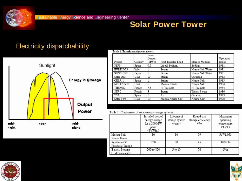
Solar Power Tower
Electricity dispatchability

Sustainable Energy Science and Engineering Center
Solar Power TowerThermal Loss

Sustainable Energy Science and Engineering Center
Solar Power Tower
Variable Load

Sustainable Energy Science and Engineering Center
Relatively few heliostats have been manufactured to date at a cost of about $250/m2.
Surface area: 150 m2
Low cost manufacturing methods are needed to make solar power tower viable technology for electricity production. Particularly, a low cost drive systems must be developed.
Heliostats

Sustainable Energy Science and Engineering Center
Receiver:
Smaller and simpler receivers are needed to improve efficiency and reduce maintenance.
Molten salt:
Molten nitrate salt, though an excellent thermal storage medium, it is not an ideal material due to its relatively high freezing point of 220oC.
Solar Power Tower

Sustainable Energy Science and Engineering Center
Solar Power Tower

Sustainable Energy Science and Engineering Center
Parabolic-Trough Technology
Solar-electric efficiency : 10%
Levelized energy cost: $0.04-0.05/kWh
Solar Electric Generating Station (SEGS)

Sustainable Energy Science and Engineering Center
Parabolic-Trough TechnologyComponents

Sustainable Energy Science and Engineering Center
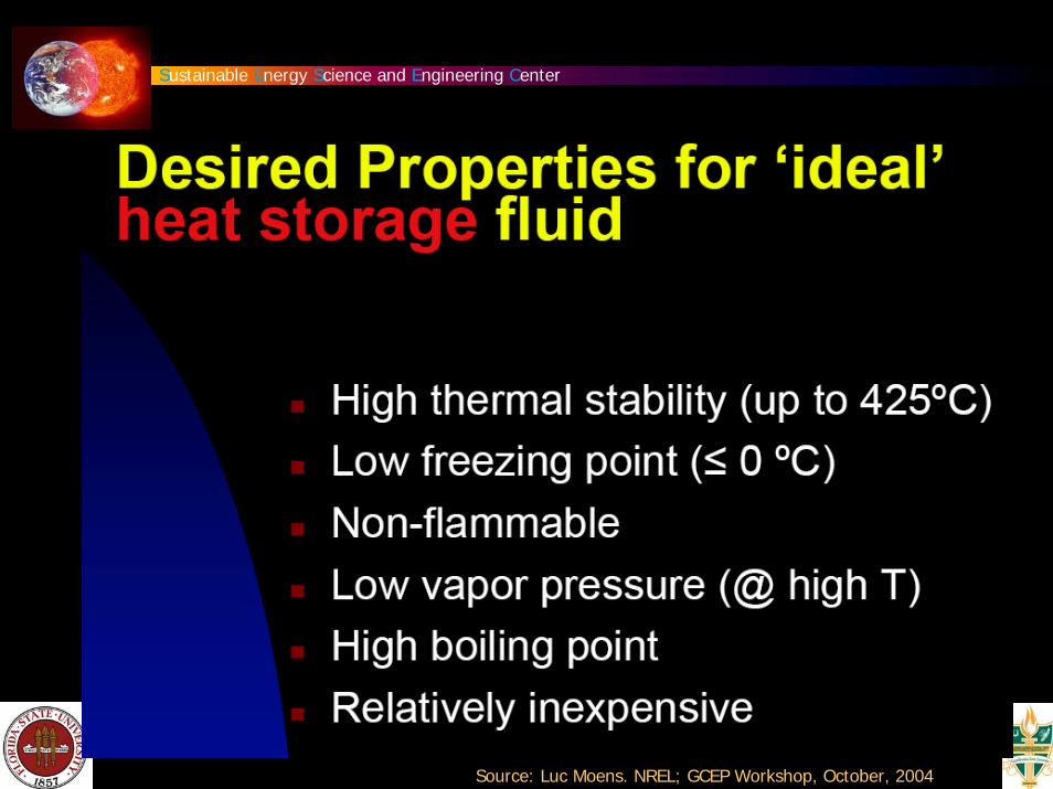
High Temperature Fluids
Source: Luc Moens. NREL; GCEP Workshop, October, 2004

Sustainable Energy Science and Engineering Center
Source: Luc Moens. NREL; GCEP Workshop, October, 2004
Sustainable Energy Science and Engineering Center
Source: Luc Moens. NREL; GCEP Workshop, October, 2004

Sustainable Energy Science and Engineering Center
US Development Activity
Source: National Renewable Energy Laboratory
Parabolic-Trough Technology

Sustainable Energy Science and Engineering Center
Solar Dish-Engine System
Dish diameter: 10m

Sustainable Energy Science and Engineering Center
Use of Heat pipes
Solar Dish-Engine System
Use of Sterling Engine

Sustainable Energy Science and Engineering Center
Solar Dish-Engine System

Sustainable Energy Science and Engineering Center
Solar Dish-Engine System
Use of Metal Hydrides
Source:

Sustainable Energy Science and Engineering Center
Solar Dish-Engine System

Sustainable Energy Science and Engineering Center
Advanced Tower

Sustainable Energy Science and Engineering Center
(a) parabolic trough collector
(b) linear Fresnel collector
(c) central receiver system with dish collector and
(d) central receiver system with distributed reflectors
Sun Radiation Concentration

Sustainable Energy Science and Engineering Center
A solar chimney power plant has a high chimney (tower), with a height of up to 1000 m, and this is surrounded by a large collector roof, up to 130 m in diameter, that consists of glass or resistive plastic supported on a framework (see artist’s impression). Towards its centre, the roof curves upwards to join the chimney, creating a funnel. The sun heats up the ground and the air underneath the collector roof, and the heated air follows the upward incline of the roof until it reaches the chimney. There, it flows at high speed through the chimney and drives wind generators at its bottom. The ground under the collector roof behaves as a storage medium, and can even heat up the air for a significant time after sunset. The efficiency of the solar chimney power plant is below 2%, and depends mainly on the height of the tower, and so these power plants can only be constructed on land which is very cheap or free. Such areas are usually situated in desert regions. However, the whole power plant is not without other uses, as the outer area under the collector roof can also be utilized as a greenhouse for agricultural purposes. As with trough and tower plants, the minimum economical size of solar chimney power plants is also in the multi-megawatt range.
Source: www.sbp.de
Solar Chimney/Tower

Sustainable Energy Science and Engineering Center
Solar Chimney/Tower
Power output:
Power output:
solar input:ÝQ Ý Q solar
P P = Ý Q solarηcollηtowerηturbine = Ý Q solarηplant
Ý Q solar = Gh Acoll
Global horizontal radiation
The tower converts the heat flow column produced by the collector into kinetic energy and potential energy. The density difference of the air caused by the temperature rise in the collector works as driving force. The lighter of air in the tower is connected with the surrounding atmosphere at the base and at the top of the tower. Hence a pressure difference is produced between tower base and the ambient:
Δptot = g ρa − ρtower( )o
Htower
∫ dH = Δpstatic + Δpdynamic
Ptot = ΔptotVtower,max Acoll
ηtower =Ptot
Ý Q =
12
Ý m Vtower,max2
Ý Q
Vtower,max = 2gHtowerΔTTo
ηtower =gHcpTo

Sustainable Energy Science and Engineering Center
Solar Chimney/Tower

Sustainable Energy Science and Engineering Center
Solar Chimney/Tower

Sustainable Energy Science and Engineering Center
Levelized Energy Cost

Sustainable Energy Science and Engineering Center
Commercial Solar Plant Costs
Levelized energy cost
Solar Electric Generating Systems (SEGS)

Sustainable Energy Science and Engineering Center
The Solar Resource
Daggett, California
Peak radiation: 1030 W/m2
Full Day: 10.6 kWh/m2

Sustainable Energy Science and Engineering Center
Solar Thermal Plant Power Output

Sustainable Energy Science and Engineering Center
Southwest Strategy
Source: Luc Moens. NREL; GCEP Workshop, October, 2004

Sustainable Energy Science and Engineering Center
Solar Thermal Power Plant Potential
Comparably low power generation costs can be achieved wherever insolation reaches 1,900 kWh per square meter and year or more. Adequate areas would be e.g. Northern and Southern Africa, the Arabic peninsula, large areas of India, Central and Western Australia, the high plateaus of the Andes states, the Northeast of Brazil, northern Mexico and the Southwest of the United States. Potential sites in Europe are located in Spain, Italy, Greece and on some Mediterranean islands.