powerpoint presentationmshashmi/ctd_2017/lecture_slides/lect_3_2017.pdf · • this circuit finds...
TRANSCRIPT

Lecture – 3 Date: 07.08.2017
• First-Order Circuit – Review
ECE 215

First Order Circuit
• A first order circuit is characterizedby first-order differential equation
in two types of configs: a) RL Circuitb) RC Circuit
Two possible scenarios: (a) without
excitation, (b) with excitation
This will result when the dc source is suddenly disconnected and in this scenario the energy stored in the capacitor gets released to the resistors.
Need to determine 𝑣(𝑡), 𝑖𝑐(𝑡), and 𝑖𝑅(𝑡)
Assume: 𝑣 0 = 𝑉0 Initial charging voltage of the capacitor
Therefore the energy stored in the capacitor: 2
0
1(0)
2w CV
KCL gives: 0C Ri i 0dv v
Cdt R
1dv
dtv RC
ln lnt
v ARC
( )tRCv t Ae

First Order Circuit (contd.)
From initial condition: 0(0)v A V 0( )
tRCv t V e
Exponential
DecayNatural Response
The time constant of a circuit is the time required for the response to
decay to a factor of 𝟏 𝒆
0( )( )
tRC
R
v t Vi t e
R R
The power dissipated in the resistor 2
20( ) ( )
tRC
R
Vp t vi t e
R
• The energy absorbed by the resistor up to time 𝑡 is: 2
2
0
0
1( ) ( ) 1
2
tt
Rw t p j dj CV e
For 𝑡 → ∞ we get 𝑤𝑅(∞) →1
2𝐶𝑉0
2

Example – 1
In the circuit shown:
(a) Find the values of R and C.(b) Calculate the time constant 𝜏.(c) Determine the time required for the voltage to decay half its initial value at t = 0.
Example – 2
Find 𝑣0(𝑡) for t > 0. Determine thetime necessary for the capacitorvoltage to decay to one-third of itsvalue at t = 0.

First Order Circuit (contd.) Assume, at t = 0: 𝑖 0 = 𝐼0
Stored energy in the inductor:2
0
1(0)
2w LI
Power dissipated in R
• The energy absorbed by R up to time 𝑡 is: 2
2
0
0
1( ) ( ) 1
2
tt
Rw t p j dj LI e
For 𝑡 → ∞ we get 𝑤𝑅(∞) →1
2𝐿𝐼0
2
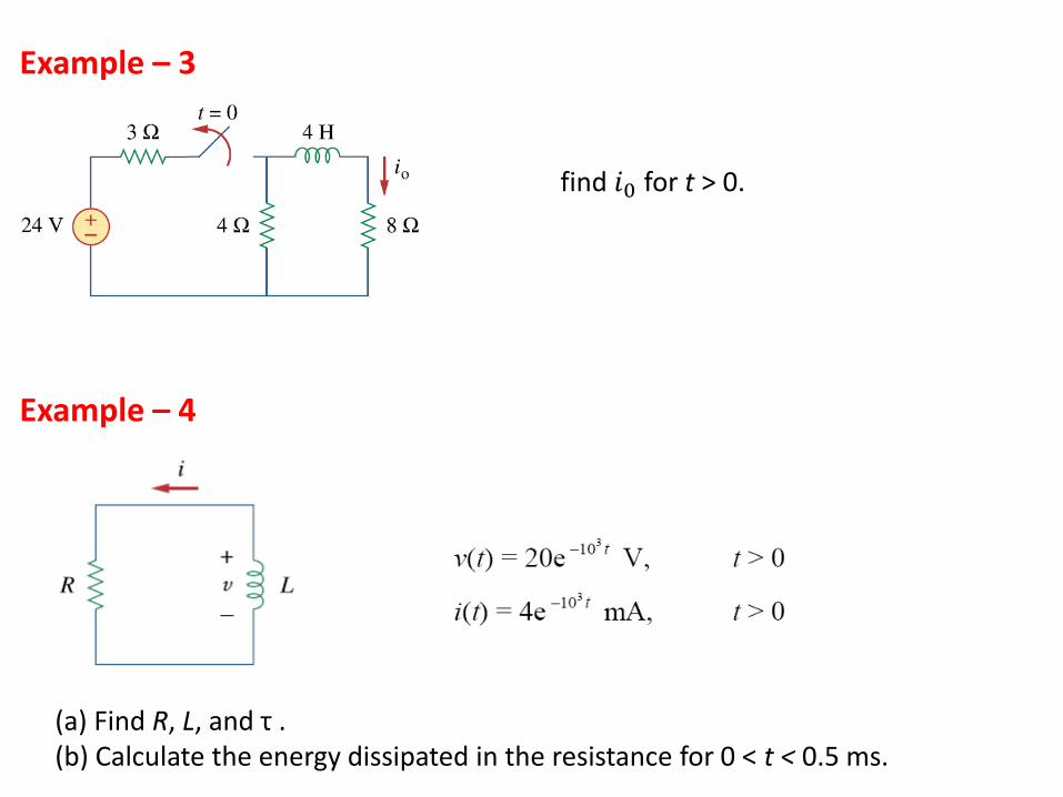
Example – 3
find 𝑖0 for t > 0.
Example – 4
(a) Find R, L, and τ .(b) Calculate the energy dissipated in the resistance for 0 < t < 0.5 ms.

Step Response of an RC Circuit
Switch ON at t=0
Assume an initial voltage V0 on the capacitor
• Voltage on a capacitor cannot change instantaneously: 0(0 ) (0 )v v V
• For 𝑡 > 0:
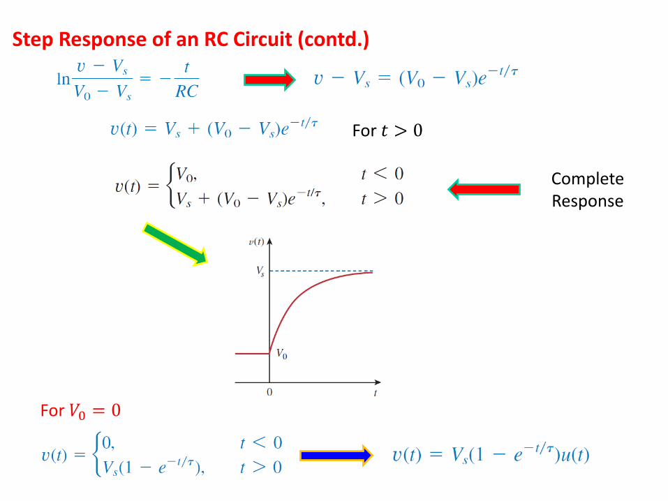
Step Response of an RC Circuit (contd.)
For 𝑡 > 0
Complete Response
For 𝑉0 = 0
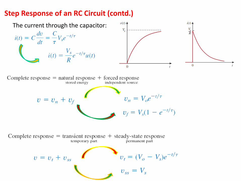
Step Response of an RC Circuit (contd.)
The current through the capacitor:

Step Response of an RC Circuit (contd.)
• Essentially we can express:
• For the determination of the step response of an RC circuit we require:
1. The initial capacitor voltage 𝑣(0)2. The final capacitor voltage 𝑣(∞)3. The time constant 𝜏.
We can obtain 𝑣(0) from the given circuit for t<0 and 𝑣(∞)and 𝜏 from the circuit for t>0.
Example – 5
Calculate the capacitor voltage for t < 0 and t > 0 for both the circuits.

Step Response of an RL Circuit
Complete Response:
• Now the current through the inductor cannot change instantaneously:
At t=0:
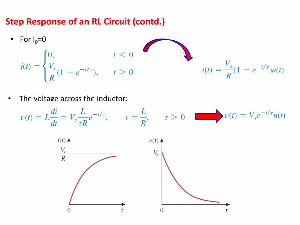
Step Response of an RL Circuit (contd.)
• For I0=0
• The voltage across the inductor:
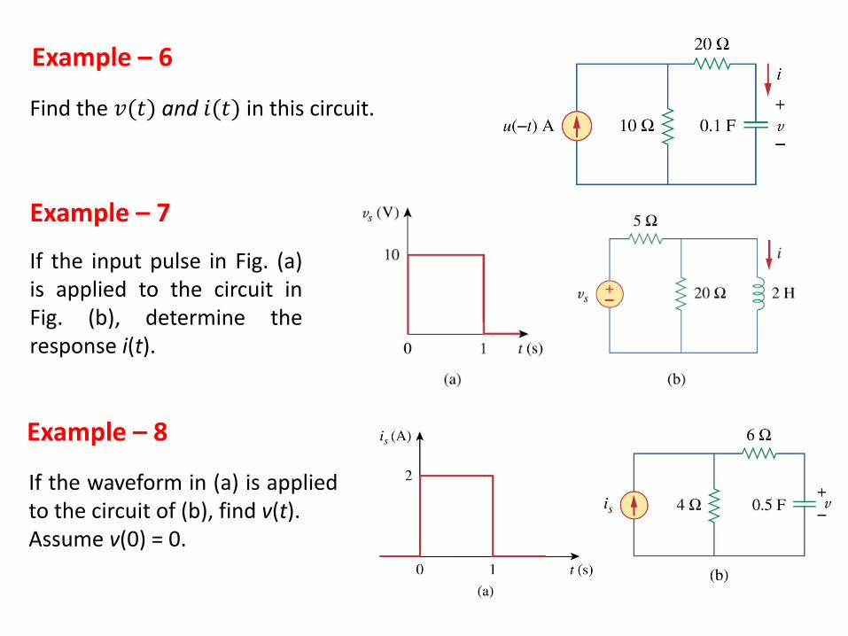
Example – 6
Find the 𝑣(𝑡) and 𝑖(𝑡) in this circuit.
Example – 7
If the input pulse in Fig. (a)is applied to the circuit inFig. (b), determine theresponse i(t).
Example – 8
If the waveform in (a) is appliedto the circuit of (b), find v(t).Assume v(0) = 0.

Photo Flash Unit
• An electronic flash unit is a commonexample of an RC circuit.
• This exploits the ability of the capacitor tooppose any abrupt change in voltage.
It consists of a high-voltage dc supply, a current-limiting large resistor R1 and a capacitor C in parallel with the flash lamp of low Resistance R2.
• When the switch is in position 1,the capacitor charges slowly due tothe large time constant (R1C ).
• the capacitor voltage risesgradually from zero to 𝑉𝑠 while itscurrent decreases gradually from(I1= 𝑉𝑠/R) to zero.
The charging time is approximately five times the time constant: 𝑡𝑐ℎ𝑎𝑟𝑔𝑒 = 5𝑅1𝐶

Photo Flash Unit (contd.)
• With the switch in position 2, thecapacitor voltage is discharged.
• The low resistance R2 of the photo lamppermits a high discharge current withpeak [I2= 𝑉𝑠/R2] in a short duration
Discharging takes place in approximately five times the time
constant: 𝑡𝑑𝑖𝑠𝑐ℎ𝑎𝑟𝑔𝑒 = 5𝑅2𝐶
• This simple RC circuit provides a short-duration and high current pulse.• This circuit finds applications in electric spot welding and radar transmitter tube.

Example – 9
The Figure shows a circuit for setting thelength of time voltage is applied to theelectrodes of a welding machine. Thetime is taken as how long it takes thecapacitor to charge from 0 to 8 V. Whatis the time range covered by the variableresistor?
Example – 10
A simple relaxation oscillator circuit isshown. The neon lamp fires when itsvoltage reaches 75V and turns off when itsvoltage drops to 30V. Its resistance is 120Ωwhen on and infinitely high when off.
(a) For how long is the lamp on each time the capacitor discharges?(b) What is the time interval between light flashes?

Relay Circuit• Relay, a magnetically controlled switch, is essentially
an electromagnetic device used to open or close aswitch that controls another circuit.
• The coil circuit is an RL circuit, where R and L are theresistance and inductance of the coil.
• the coil circuit is energized once switch S1 is closed.• The coil current gradually increases and produces a magnetic field. Eventually
the magnetic field is sufficiently strong to pull the movable contact in the othercircuit and close switch S2.
Relays were used in the earliest digital circuits and are still used in high-power circuits.
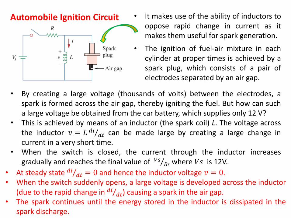
Automobile Ignition Circuit • It makes use of the ability of inductors tooppose rapid change in current as itmakes them useful for spark generation.
• By creating a large voltage (thousands of volts) between the electrodes, aspark is formed across the air gap, thereby igniting the fuel. But how can sucha large voltage be obtained from the car battery, which supplies only 12 V?
• This is achieved by means of an inductor (the spark coil) L. The voltage acrossthe inductor 𝑣 = 𝐿 𝑑𝑖
𝑑𝑡 can be made large by creating a large change incurrent in a very short time.
• When the switch is closed, the current through the inductor increasesgradually and reaches the final value of 𝑉𝑠
𝑅, where 𝑉𝑠 is 12V.
• The ignition of fuel-air mixture in eachcylinder at proper times is achieved by aspark plug, which consists of a pair ofelectrodes separated by an air gap.
• At steady state 𝑑𝑖𝑑𝑡 = 0 and hence the inductor voltage 𝑣 = 0.
• When the switch suddenly opens, a large voltage is developed across the inductor(due to the rapid change in 𝑑𝑖
𝑑𝑡) causing a spark in the air gap.• The spark continues until the energy stored in the inductor is dissipated in the
spark discharge.