powerpoint presentationseaoo.org/.../2014_seaoo_conference___design_construction...huff_.pdf ·...
TRANSCRIPT
8/27/2014
1
Design/Construction Considerations
for Tied-back Shoring Systems
Structural Engineers Association of Ohio
September 11, 2014
Presented by
Richard Goettle, Inc. Jonathan Huff, P.E.
A. Tieback Wall Components
B. Lateral Earth Pressure Design Considerations
C. Soldier Pile / Anchor Design
D. Lagging Design
E. Anchor Testing Requirements
F. Bottom of Excavation Considerations
G. Case Study
Design/Construction Considerations
for Tied-back Shoring Systems
Design/Construction Considerations – Soldier Piles Design/Construction Considerations – Soldier Piles
Design/Construction Considerations – Soldier Piles Design/Construction Considerations – Soldier Piles
8/27/2014
2
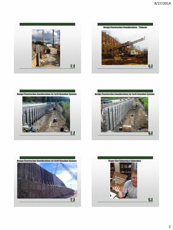
Design/Construction Considerations - Tiebacks
Design/Construction Considerations for Earth Retention Systems Design/Construction Considerations for Earth Retention Systems
Design/Construction Considerations for Earth Retention Systems Proper Site/Subsurface Exploration
8/27/2014
3
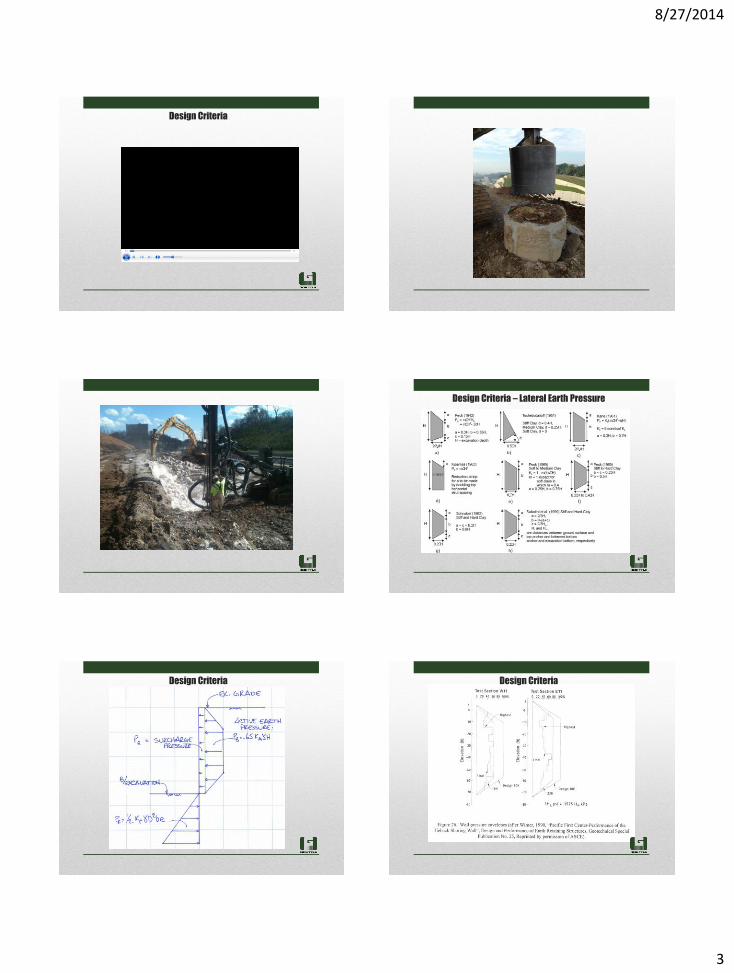
Design Criteria
Design Criteria – Lateral Earth Pressure
Design Criteria Design Criteria
8/27/2014
4
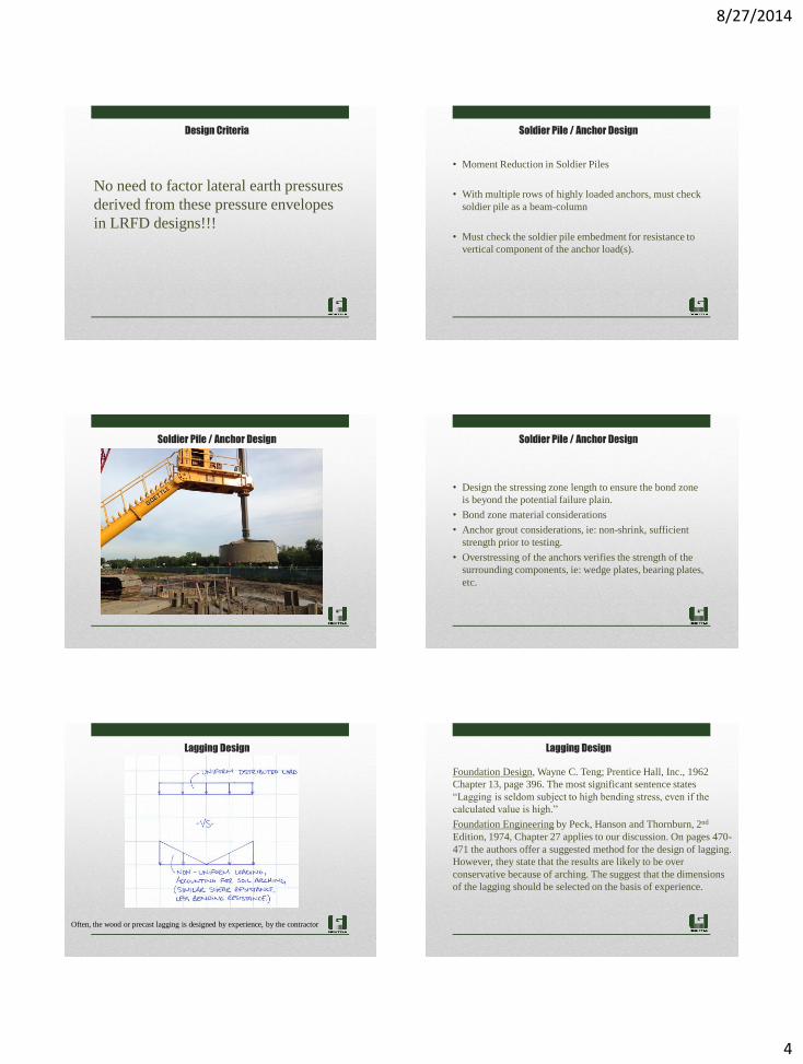
No need to factor lateral earth pressures
derived from these pressure envelopes
in LRFD designs!!!
Design Criteria
• Moment Reduction in Soldier Piles
• With multiple rows of highly loaded anchors, must check
soldier pile as a beam-column
• Must check the soldier pile embedment for resistance to
vertical component of the anchor load(s).
Soldier Pile / Anchor Design
Soldier Pile / Anchor Design
• Design the stressing zone length to ensure the bond zone
is beyond the potential failure plain.
• Bond zone material considerations
• Anchor grout considerations, ie: non-shrink, sufficient
strength prior to testing.
• Overstressing of the anchors verifies the strength of the
surrounding components, ie: wedge plates, bearing plates,
etc.
Soldier Pile / Anchor Design
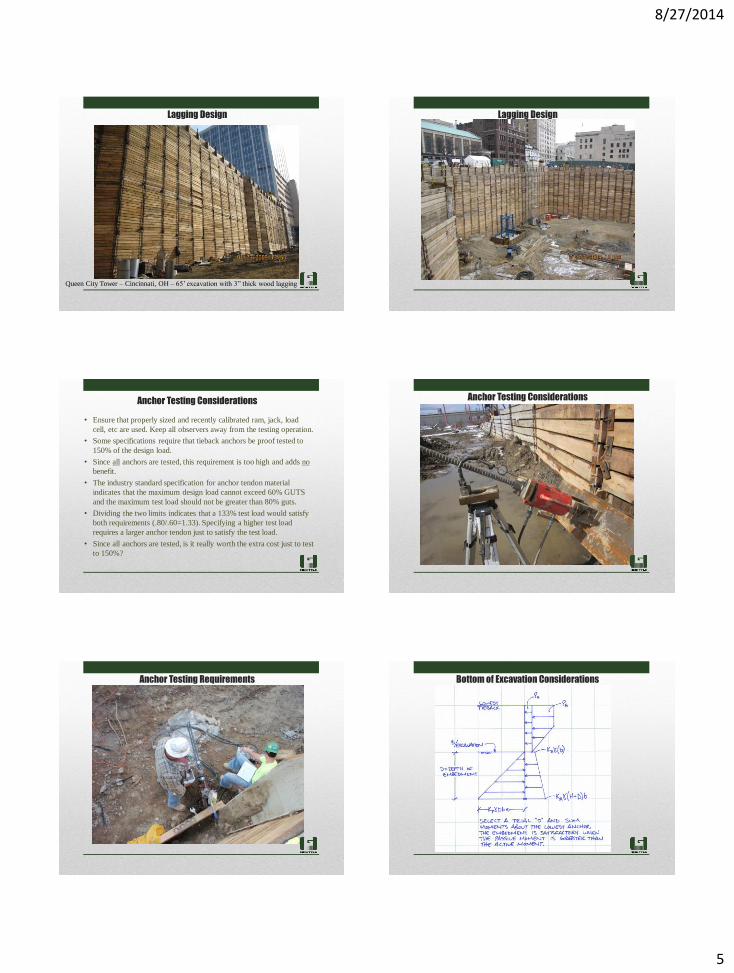
Often, the wood or precast lagging is designed by experience, by the contractor
Lagging Design
Foundation Design, Wayne C. Teng; Prentice Hall, Inc., 1962
Chapter 13, page 396. The most significant sentence states
“Lagging is seldom subject to high bending stress, even if the
calculated value is high.”
Foundation Engineering by Peck, Hanson and Thornburn, 2nd
Edition, 1974, Chapter 27 applies to our discussion. On pages 470-
471 the authors offer a suggested method for the design of lagging.
However, they state that the results are likely to be over
conservative because of arching. The suggest that the dimensions
of the lagging should be selected on the basis of experience.
Lagging Design
8/27/2014
5
Queen City Tower – Cincinnati, OH – 65’ excavation with 3” thick wood lagging
Lagging Design Lagging Design
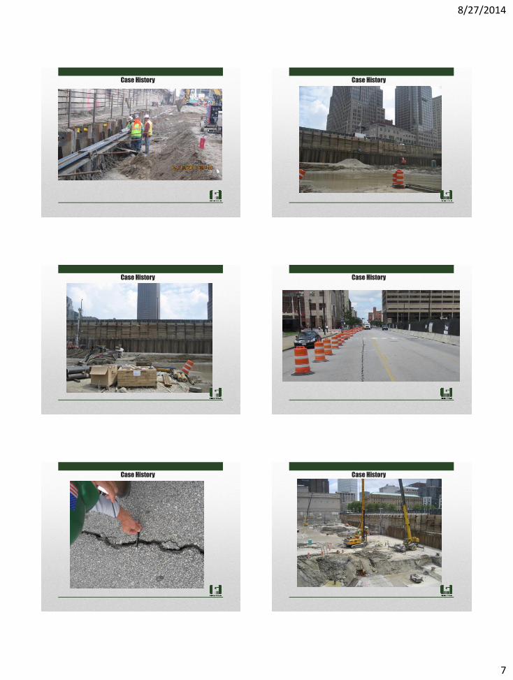
• Ensure that properly sized and recently calibrated ram, jack, load
cell, etc are used. Keep all observers away from the testing operation.
• Some specifications require that tieback anchors be proof tested to
150% of the design load.
• Since all anchors are tested, this requirement is too high and adds no
benefit.
• The industry standard specification for anchor tendon material
indicates that the maximum design load cannot exceed 60% GUTS
and the maximum test load should not be greater than 80% guts.
• Dividing the two limits indicates that a 133% test load would satisfy
both requirements (.80/.60=1.33). Specifying a higher test load
requires a larger anchor tendon just to satisfy the test load.
• Since all anchors are tested, is it really worth the extra cost just to test
to 150%?
Anchor Testing Considerations Anchor Testing Considerations
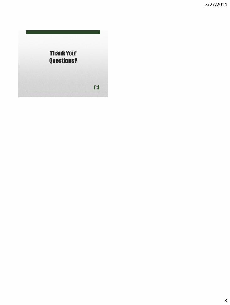
Anchor Testing Requirements Bottom of Excavation Considerations
8/27/2014
6
Bottom of Excavation Considerations Bottom of Excavation Considerations
Case History Case History
Case History Case History
8/27/2014
7
Case History Case History
Case History Case History
Case History Case History
8/27/2014
8
Thank You!
Questions?