powerohm resistors digital hrg system · powerohm resistors digital hrg system 7 publication 247-en...
TRANSCRIPT
Publication 247-EN – September 2017
Installation and Operating Instructions
Powerohm Resistors Digital HRG System
This manual provides general information, installation, operation, maintenance,
and system setup information for the Powerohm Resistors Digital HRG System.
Section Page
Equipment Application 3
Installation 4
Operator Interface Device (OID) Use and Navigation 7
Equipment Operation 14
Measure Capacitance and Adjust Taps 16
Maintenance 18
Replacement Parts 20

2 Powerohm Resistors Digital HRG System
Publication 247-EN – September 2017
History of Changes
Rev. No. Date Description of Changes
A September 2017 Initial Release

Powerohm Resistors Digital HRG System 3
Publication 247-EN – September 2017
Equipment Application Powerohm Resistors Digital HRG Systems are an economical means of
improving a three-phase ungrounded power system by providing the following
advantages:
System Protection: Offers protection by providing a ground-to-neutral
connection for a three-phase power system, while still allowing it to operate as
an “ungrounded system,” When the neutral of a system is not grounded, the
system is vulnerable to potentially damaging ground faults.
Transient Over-voltage Reduction: A high resistance grounding system
reduces the magnitude of transient over-voltages that may occur during arcing
ground faults. High transient over-voltages may cause failure of equipment or
insulation at locations on the system other than at the point of the fault.
Ground Fault Detection Warning: Instantly provides a warning when the first
ground fault occurs through an alarm signal. Form C contacts can be used to
activate external alarms or annunciators. An audible horn and optional red
warning beacon is available.
Ground Fault Location Simplified: A pulsing contactor allows the ground
fault location to be quickly located by use of a portable clamp-on current
detector. The ease and swiftness of ground fault location eliminates the need to
trace faults by opening and closing secondary feeders, branch circuits, and
individual loads one at a time.
Uninterrupted Service: A single line-to-ground fault left in operation may
develop into a phase-to-phase fault, which is caused by the occurrence of a
second ground fault on another phase before the first fault is cleared.
Considerable damage may be caused by the high line-to-line fault current. The
potential for quickly locating and removing faults before damage occurs to
critical processes minimizes outages and costly manufacturing shutdowns.
Improved Personnel Safety: Reduced transient over-voltages, equipment
arcing, fault levels, insulation failures, and fault tracing through circuit isolation
schemes decreases hazards to personnel.
4 Powerohm Resistors Digital HRG System
Publication 247-EN – September 2017
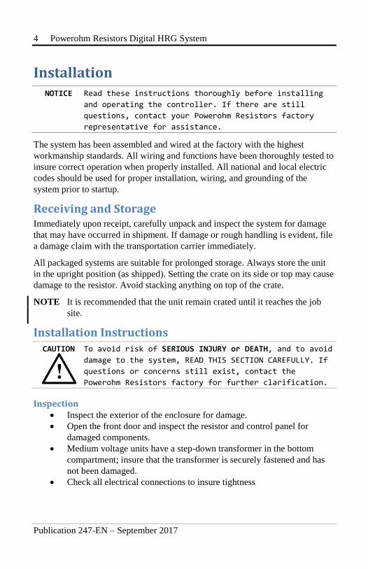
Installation NOTICE Read these instructions thoroughly before installing
and operating the controller. If there are still
questions, contact your Powerohm Resistors factory
representative for assistance.
The system has been assembled and wired at the factory with the highest
workmanship standards. All wiring and functions have been thoroughly tested to
insure correct operation when properly installed. All national and local electric
codes should be used for proper installation, wiring, and grounding of the
system prior to startup.
Receiving and Storage Immediately upon receipt, carefully unpack and inspect the system for damage
that may have occurred in shipment. If damage or rough handling is evident, file
a damage claim with the transportation carrier immediately.
All packaged systems are suitable for prolonged storage. Always store the unit
in the upright position (as shipped). Setting the crate on its side or top may cause
damage to the resistor. Avoid stacking anything on top of the crate.
NOTE It is recommended that the unit remain crated until it reaches the job
site.
Installation Instructions
CAUTION To avoid risk of SERIOUS INJURY or DEATH, and to avoid
damage to the system, READ THIS SECTION CAREFULLY. If
questions or concerns still exist, contact the
Powerohm Resistors factory for further clarification.
Inspection Inspect the exterior of the enclosure for damage.
Open the front door and inspect the resistor and control panel for
damaged components.
Medium voltage units have a step-down transformer in the bottom
compartment; insure that the transformer is securely fastened and has
not been damaged.
Check all electrical connections to insure tightness
Powerohm Resistors Digital HRG System 5
Publication 247-EN – September 2017
NOTE If damaged parts are found, contact the factory immediately.
Energizing the unit may damage the resistor and create a shock hazard
to personnel.
Handling Freestanding units are supplied with removable lifting eyes for use with an
overhead crane. Do not attempt to move or lift the equipment at points other
than the lifting eyes or skid base. Never position the unit on its side or top,
which may cause damage to the unit. Wall mounted units and open panels
should also be handled with care to prevent damage to extern components. Do
not stack.
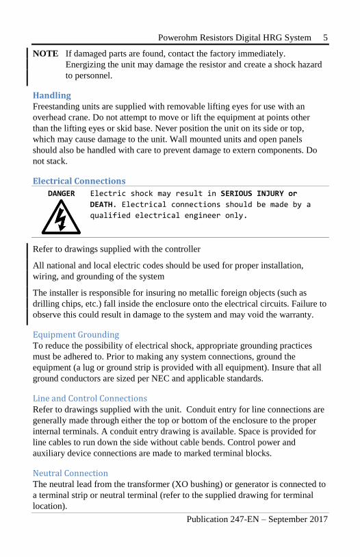
Electrical Connections
DANGER Electric shock may result in SERIOUS INJURY or
DEATH. Electrical connections should be made by a
qualified electrical engineer only.
Refer to drawings supplied with the controller
All national and local electric codes should be used for proper installation,
wiring, and grounding of the system
The installer is responsible for insuring no metallic foreign objects (such as
drilling chips, etc.) fall inside the enclosure onto the electrical circuits. Failure to
observe this could result in damage to the system and may void the warranty.
Equipment Grounding To reduce the possibility of electrical shock, appropriate grounding practices
must be adhered to. Prior to making any system connections, ground the
equipment (a lug or ground strip is provided with all equipment). Insure that all
ground conductors are sized per NEC and applicable standards.
Line and Control Connections Refer to drawings supplied with the unit. Conduit entry for line connections are
generally made through either the top or bottom of the enclosure to the proper
internal terminals. A conduit entry drawing is available. Space is provided for
line cables to run down the side without cable bends. Control power and
auxiliary device connections are made to marked terminal blocks.
Neutral Connection The neutral lead from the transformer (XO bushing) or generator is connected to
a terminal strip or neutral terminal (refer to the supplied drawing for terminal
location).

6 Powerohm Resistors Digital HRG System
Publication 247-EN – September 2017
The connection is made directly to an internal terminal point via rigid conduit
connected to the enclosure. On medium voltage units, the neutral cable is
terminated to the transformer H1 terminal or a NEMA two-hole terminal with a
compression type lug (customer supplied). Neutral conductor is sized per NEC
§250. Location and termination of the conduit is the customer’s responsibility.
NOTE The factory supplied drawing identifies the neutral and ground
connection points, and the proper connection is shown schematically.
Delta Phase Connection The phase leads from the transformer or generator are connected to a terminal
strip on low voltage units (refer to the supplied drawings for terminal locations).
On medium voltage units the connection is made directly to the neutral deriving
transformers via rigid conduit connected to the enclosure. The cables are
terminated with a compression type lug (customer supplied) to the transformer
H1 terminals. Location and termination of the conduit is the customer’s
responsibility.
NOTE The factory supplied drawing identifies the phase and ground
connection points. This grounding equipment is not phase rotation
sensitive. Any phase can connect to any H1 terminal.
Ground Connection The ground lead from the resistive element to ground may be connected one of
two ways:
1. On low voltage units the connection is made directly to a control panel
mounted ground bus.
2. Medium voltage units have separate grounds for the high voltage
ground and a low voltage ground to the secondary of the step-down
transformer(s). The HV ground connection is made directly to an
internal ½” ground stud via rigid conduit connected to the enclosure.
The ground terminal is labeled for easy identification. A compression
type lug (customer supplied) is used for ground connection. The low
voltage secondary ground connection is made directly to a control
panel mounted ground bus. Location and termination of the conduit is
the customer’s responsibility.
NOTE The factory supplied drawing identifies the neutral and ground
connections.
Powerohm Resistors Digital HRG System 7
Publication 247-EN – September 2017
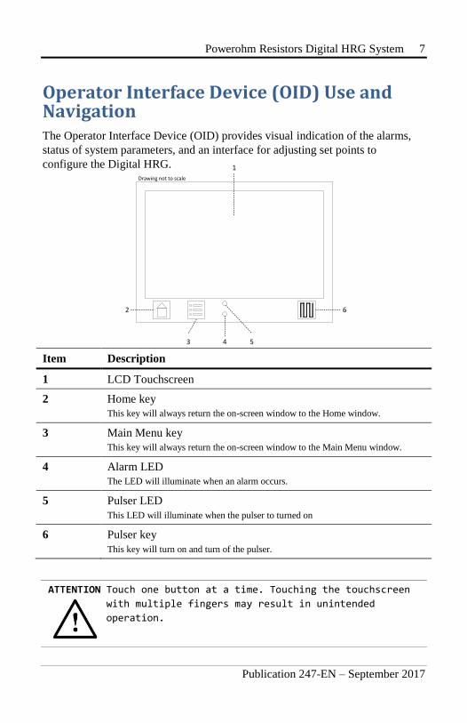
Operator Interface Device (OID) Use and Navigation The Operator Interface Device (OID) provides visual indication of the alarms,
status of system parameters, and an interface for adjusting set points to
configure the Digital HRG.
Item Description
1 LCD Touchscreen
2 Home key
This key will always return the on-screen window to the Home window.
3 Main Menu key
This key will always return the on-screen window to the Main Menu window.
4 Alarm LED
The LED will illuminate when an alarm occurs.
5 Pulser LED
This LED will illuminate when the pulser to turned on
6 Pulser key
This key will turn on and turn of the pulser.
ATTENTION Touch one button at a time. Touching the touchscreen
with multiple fingers may result in unintended
operation.
1
Drawing not to scale
2
3 5
6
4

8 Powerohm Resistors Digital HRG System
Publication 247-EN – September 2017
Home Window
Item Description
1 Window Status Bar Displays the date, time, and background activity such as downloading to a USB memory stick.
2 Current Panel Displays the neutral current and the fault current set point value. It will also blink
“PULSER ON” when pulsing.
3 Voltage Panel Displays the neutral voltage and the voltage for all three phases.
4 Alarm Panel Displays the list of active and recent alarms. Touching a “cleared” alarm will
remove it from the list. The panel will not be displayed if there are no active or
recent alarms in the list.
Drawing not to scale
2
3
4
1 12:00 p.m.
Powerohm Resistors Digital HRG System 9
Publication 247-EN – September 2017
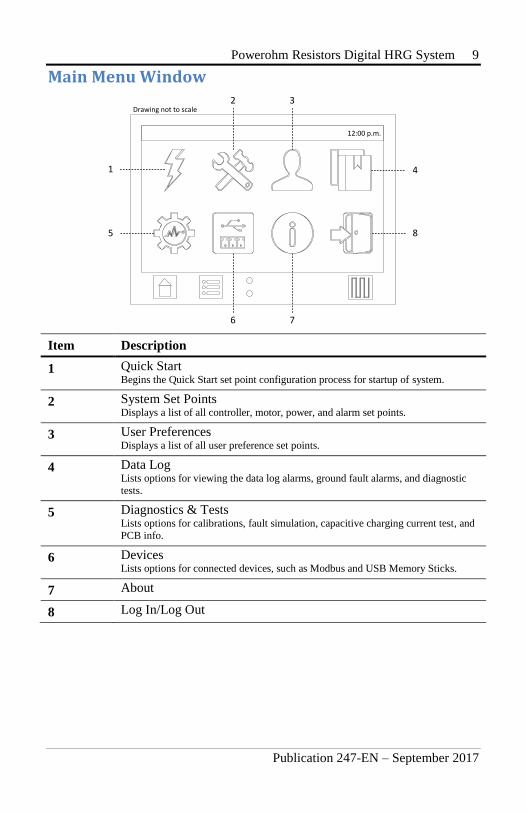
Main Menu Window
Item Description
1 Quick Start Begins the Quick Start set point configuration process for startup of system.
2 System Set Points Displays a list of all controller, motor, power, and alarm set points.
3 User Preferences Displays a list of all user preference set points.
4 Data Log Lists options for viewing the data log alarms, ground fault alarms, and diagnostic
tests.
5 Diagnostics & Tests Lists options for calibrations, fault simulation, capacitive charging current test, and
PCB info.
6 Devices Lists options for connected devices, such as Modbus and USB Memory Sticks.
7 About
8 Log In/Log Out
1
Drawing not to scale
5
2 3
4
8
6 7
12:00 p.m.

10 Powerohm Resistors Digital HRG System
Publication 247-EN – September 2017
User Log In Navigating and viewing set point configurations is allowed at all times;
however, changing any set point configuration requires the user password. The
user password is shown below. This password is also on a label affixed to the
enclosure door on the inside.
When prompted for the user password, enter the following pin number:
1 2 3 3 3 3
Logging Out If there is no user activity on the OID for five minutes, the login state is
automatically logged out.
To manually log out From the Main Menu window, touch the Log Out button.
Powerohm Resistors Digital HRG System 11
Publication 247-EN – September 2017
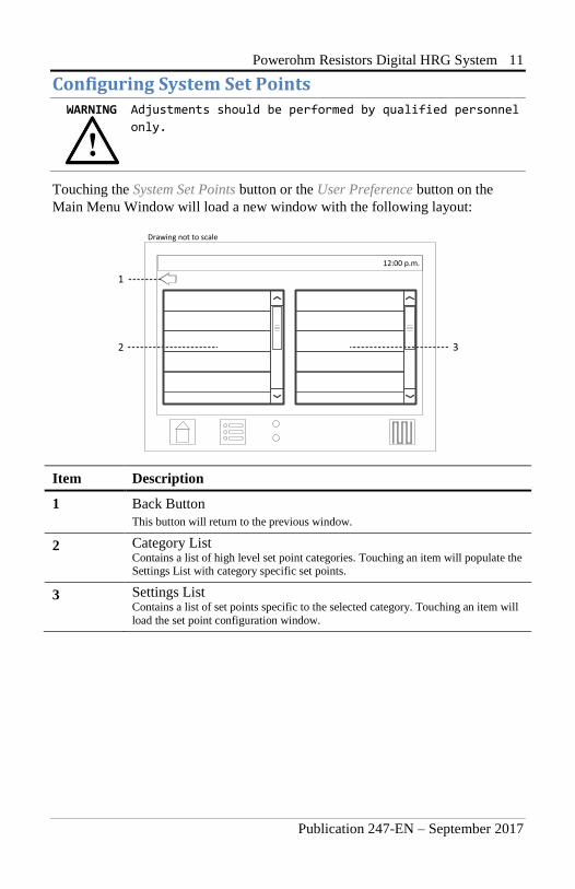
Configuring System Set Points
WARNING Adjustments should be performed by qualified personnel
only.
Touching the System Set Points button or the User Preference button on the
Main Menu Window will load a new window with the following layout:
Item Description
1 Back Button
This button will return to the previous window.
2 Category List Contains a list of high level set point categories. Touching an item will populate the Settings List with category specific set points.
3 Settings List Contains a list of set points specific to the selected category. Touching an item will
load the set point configuration window.
Drawing not to scale
12:00 p.m.
1
2 3
12 Powerohm Resistors Digital HRG System
Publication 247-EN – September 2017
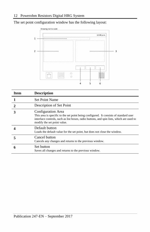
The set point configuration window has the following layout:
Item Description
1 Set Point Name
2 Description of Set Point
3 Configuration Area This area is specific to the set point being configured. It consists of standard user
interface controls, such as list boxes, radio buttons, and spin lists, which are used to
modify the set point value.
4 Default button Loads the default value for the set point, but does not close the window.
5 Cancel button Cancels any changes and returns to the previous window.
6 Set button Saves all changes and returns to the previous window.
2
Drawing not to scale
4
3
5 6
12:00 p.m.
1
Powerohm Resistors Digital HRG System 13
Publication 247-EN – September 2017
Quick Start The quick start feature is used to sequentially configure the primary system set
points without having to navigate through the onscreen menu. The following set
points are configured: TBD.
Refer to Main Menu Window, Item 1, on page 9 above.
To perform a quick start:
1. From the Main Menu window, touch Quick Start.
2. Configure each set point one at a time, pressing the Next button to
move to the next set point.
3. A summary will be displayed after the last set point has been
configured. Press the Save button to save all set points.
4. The window will return to the Main Menu window.
NOTE Canceling the Quick Start process will discard all changes.
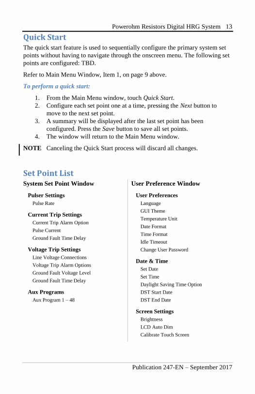
Set Point List System Set Point Window
Pulser Settings
Pulse Rate
Current Trip Settings
Current Trip Alarm Option
Pulse Current
Ground Fault Time Delay
Voltage Trip Settings
Line Voltage Connections
Voltage Trip Alarm Options
Ground Fault Voltage Level
Ground Fault Time Delay
Aux Programs
Aux Program 1 – 48
User Preference Window
User Preferences
Language
GUI Theme
Temperature Unit
Date Format
Time Format
Idle Timeout
Change User Password
Date & Time
Set Date
Set Time
Daylight Saving Time Option
DST Start Date
DST End Date
Screen Settings
Brightness
LCD Auto Dim
Calibrate Touch Screen
14 Powerohm Resistors Digital HRG System
Publication 247-EN – September 2017
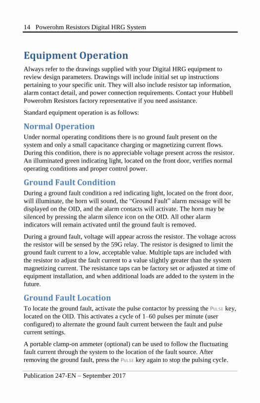
Equipment Operation Always refer to the drawings supplied with your Digital HRG equipment to
review design parameters. Drawings will include initial set up instructions
pertaining to your specific unit. They will also include resistor tap information,
alarm contact detail, and power connection requirements. Contact your Hubbell
Powerohm Resistors factory representative if you need assistance.
Standard equipment operation is as follows:
Normal Operation Under normal operating conditions there is no ground fault present on the
system and only a small capacitance charging or magnetizing current flows.
During this condition, there is no appreciable voltage present across the resistor.
An illuminated green indicating light, located on the front door, verifies normal
operating conditions and proper control power.
Ground Fault Condition During a ground fault condition a red indicating light, located on the front door,
will illuminate, the horn will sound, the “Ground Fault” alarm message will be
displayed on the OID, and the alarm contacts will activate. The horn may be
silenced by pressing the alarm silence icon on the OID. All other alarm
indicators will remain activated until the ground fault is removed.
During a ground fault, voltage will appear across the resistor. The voltage across
the resistor will be sensed by the 59G relay. The resistor is designed to limit the
ground fault current to a low, acceptable value. Multiple taps are included with
the resistor to adjust the fault current to a value slightly greater than the system
magnetizing current. The resistance taps can be factory set or adjusted at time of
equipment installation, and when additional loads are added to the system in the
future.
Ground Fault Location To locate the ground fault, activate the pulse contactor by pressing the PULSE key,
located on the OID. This activates a cycle of 1–60 pulses per minute (user
configured) to alternate the ground fault current between the fault and pulse
current settings.
A portable clamp-on ammeter (optional) can be used to follow the fluctuating
fault current through the system to the location of the fault source. After
removing the ground fault, press the PULSE key again to stop the pulsing cycle.
Powerohm Resistors Digital HRG System 15
Publication 247-EN – September 2017
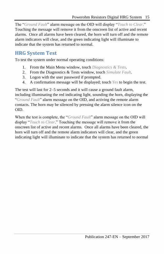
The “Ground Fault” alarm message on the OID will display “Touch to Clear.”
Touching the message will remove it from the onscreen list of active and recent
alarms. Once all alarms have been cleared, the horn will turn off and the remote
alarm indicators will clear, and the green indicating light will illuminate to
indicate that the system has returned to normal.
HRG System Test To test the system under normal operating conditions:
1. From the Main Menu window, touch Diagnostics & Tests.
2. From the Diagnostics & Tests window, touch Simulate Fault.
3. Logon with the user password if prompted.
4. A confirmation message will be displayed; touch Yes to begin the test.
The test will last for 2–5 seconds and it will cause a ground fault alarm,
including illuminating the red indicating light, sounding the horn, displaying the
“Ground Fault” alarm message on the OID, and activing the remote alarm
contacts. The horn may be silenced by pressing the alarm silence icon on the
OID.
When the test is complete, the “Ground Fault” alarm message on the OID will
display “Touch to Clear.” Touching the message will remove it from the
onscreen list of active and recent alarms. Once all alarms have been cleared, the
horn will turn off and the remote alarm indicators will clear, and the green
indicating light will illuminate to indicate that the system has returned to normal
16 Powerohm Resistors Digital HRG System
Publication 247-EN – September 2017
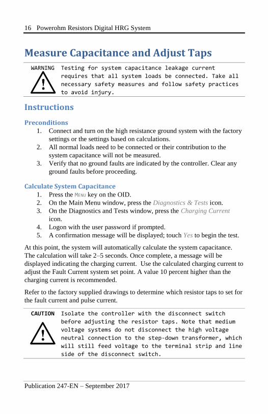
Measure Capacitance and Adjust Taps WARNING Testing for system capacitance leakage current
requires that all system loads be connected. Take all
necessary safety measures and follow safety practices
to avoid injury.
Instructions
Preconditions 1. Connect and turn on the high resistance ground system with the factory
settings or the settings based on calculations.
2. All normal loads need to be connected or their contribution to the
system capacitance will not be measured.
3. Verify that no ground faults are indicated by the controller. Clear any
ground faults before proceeding.
Calculate System Capacitance 1. Press the MENU key on the OID.
2. On the Main Menu window, press the Diagnostics & Tests icon.
3. On the Diagnostics and Tests window, press the Charging Current
icon.
4. Logon with the user password if prompted.
5. A confirmation message will be displayed; touch Yes to begin the test.
At this point, the system will automatically calculate the system capacitance.
The calculation will take 2–5 seconds. Once complete, a message will be
displayed indicating the charging current. Use the calculated charging current to
adjust the Fault Current system set point. A value 10 percent higher than the
charging current is recommended.
Refer to the factory supplied drawings to determine which resistor taps to set for
the fault current and pulse current.
CAUTION Isolate the controller with the disconnect switch
before adjusting the resistor taps. Note that medium
voltage systems do not disconnect the high voltage
neutral connection to the step-down transformer, which
will still feed voltage to the terminal strip and line
side of the disconnect switch.

Powerohm Resistors Digital HRG System 17
Publication 247-EN – September 2017
Annual Adjustments The above test to measure the system capacitance leakage current should be
performed annually, as over time additional loads may be added to the system.
Maintaining the fault setting higher than the system capacitance leakage current
allows the HRG to limit transient overvoltages, should an arcing fault develop
on the system. Fault current settings higher than recommended by the drawing
allows more damage to occur at the point of fault and may subject personnel at
the point of fault to injury.
If you have questions on this procedure, contact the Hubbell Powerohm
Resistors factory.

18 Powerohm Resistors Digital HRG System
Publication 247-EN – September 2017
Maintenance The Digital HRG requires monthly inspections for damage to insure that the
resistor is still capable of protecting the system. Damage may occur from
lightning, earthquakes, overloads, or extended service life.
The following procedure is recommended for field inspections:
1. Isolate the high resistance grounding system with the disconnect
switch. Note that medium voltage systems do not disconnect the high
voltage neutral connection to the step-down transformer, which will
still feed voltage to the terminal strip and line side of the disconnect
switch. For complete protection the system must be de-energized.
These precautions are recommended to prevent a shock hazard to
maintenance personnel and to prevent the system from being operated
without proper grounding.
2. Inspect and test the control panel.
3. Carefully check the resistor assembly for cracked ceramics or damaged
insulators. A Megger™ or Hi-Pot test is the most reliable method of
ensuring that the porcelain insulation is still providing the necessary
electrical isolation. Ground connections must be disconnected to
perform this test.
4. Check the resistive element for continuity. An ohmmeter reading made
between the neutral and the ground side of the resistor should be within
10% of the drawing values. If the resistance of the element is more than
15% off from the nameplate value, the resistors should be replaced.
5. Check all internal connections for tightness. Check wiring for signs of
damage from heat or overloads.
6. Drawings can be supplied by email or fax if we are furnished with
complete nameplate information. Finally check the mounting bolts for
tightness.
CAUTION Maintenance work should be performed by qualified
electrical personnel in compliance with national and
local safety regulations. NEC requires qualified and
trained electrical personnel to be available to
supervise operation of this equipment.
Powerohm Resistors Digital HRG System 19
Publication 247-EN – September 2017
Notes
20 Powerohm Digital HRG System
www.powerohm.com www.hubbell-icd.com
Hubbell Industrial Controls, Inc. 4301 Cheyenne Drive, Archdale NC 27263 USA
Tel: (336) 434-2800, Fax: (336) 434-2801
Powerohm Resistors 5713 13th Street, Katy TX 77493 USA
Tel: (859) 384-8088, Fax: (859) 384-8099
Publication 247-EN – September 2017 Printed in USA
Replacement Parts For replacement parts, contact your local Powerohm Resistors office or the
Hubbell Powerohm Resistors factory at:
Telephone: (800) 838-4694
Email: [email protected]
Technical Support Telephone: (336) 434-2800 ext. 183
Email: [email protected]