powermat charging spot 3 · electrical port can support up to eight charging spots with one power...
TRANSCRIPT

Each Charging Spot 3.1 is a network-connected unit, enabling you to push rThe cloud connected charging network also allows for remote monitoring, management and upgrades. Additionally, integrated beacons enable user activation of charging through the Powermat application. You can choose to install the Powermat Charging Spot 3.1 in one of two ways: Surface-mount or sub-surface.
Wirelessly charges all mobile phones
To learn more about wireless charging compatiable devices go to: https://www.powermat.com/technology/compatible-phones/
Designed for public spaces
The transfer of power is based on magnetic inductance and therefore safe even when the table’s surface is wet, and spots are designed to withstand chemicals and cleaning solvents.
Durable and easy to maintain, the Charging Spot 3.1 can be installed on most surface types.
electrical port can support up to eight Charging Spots with one power delivery unit. Our custom designed power supply unit keeps the outlet available for other needs, and secures wiring to prevent tampering.
Charging Spot 3.1, Mounted SKU: CS-001-GEN3B-INT | Sub-surface SKU: CS-001-GEN3B-SIN
The Powermat Charging Spot is a critical component of our wireless charging solution. Users place their phones on the spot and ‘connect’ with your venue, creating a new, highly personalized customer engagement channel.
Powermat Charging Spot 3.1
Sub-surface Surface-mount
Powermat Charging Spot can power all Qi and AirFuel-Inductive certified devices (i.e., iPhone 8/8Plus/X, Samsung Galaxy S6/7/8/9). Phones without built-in wireless charging can be charged with the help of a Powermat Ring.
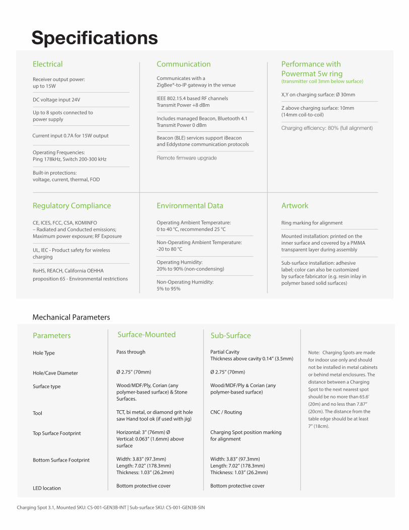
Electrical
Receiver output power:up to 15W
DC voltage input 24V
Up to 8 spots connected topower supply
Current input 0.7A for 15W output
Operating Frequencies:Ping 178kHz, Switch 200-300 kHz
Built-in protections:voltage, current, thermal, FOD
Regulatory Compliance
CE, ICES, FCC, CSA, KOMINFO– Radiated and Conducted emissions; Maximum power exposure; RF Exposure
UL, IEC - Product safety for wireless charging
RoHS, REACH, California OEHHAproposition 65 - Environmental restrictions
Hole Type
Hole/Cave Diameter
Surface type
Tool
Top Surface Footprint
Bottom Surface Footprint
LED location
Pass through
Ø 2.75” (70mm)
polymer-based surface) & Stone Surfaces.
TCT, bi metal, or diamond grit hole saw Hand tool ok (if used with jig)
Horizontal: 3” (76mm) ØVertical: 0.063” (1.6mm) above surface
Width: 3.83” (97.3mm)Length: 7.02” (178.3mm)Thickness: 1.03” (26.2mm)
Bottom protective cover
Partial Cavity Thickness above cavity 0.14” (3.5mm)
Ø 2.75” (70mm)
polymer-based surface)
CNC / Routing
Charging Spot position marking for alignment
Width: 3.83” (97.3mm)Length: 7.02” (178.3mm)Thickness: 1.03” (26.2mm)
Bottom protective cover
Environmental Data
Operating Ambient Temperature:0 to 40 °C, recommended 25 °C
Non-Operating Ambient Temperature:-20 to 80 °C
Operating Humidity:20% to 90% (non-condensing)
Non-Operating Humidity:5% to 95%
Artwork
Ring marking for alignment
Mounted installation: printed on the inner surface and covered by a PMMA transparent layer during assembly Sub-surface installation: adhesive label; color can also be customized by surface fabricator (e.g. resin inlay in polymer based solid surfaces)
Communication
Communicates with aZigBee®-to-IP gateway in the venue
IEEE 802.15.4 based RF channelsTransmit Power +8 dBm
Includes managed Beacon, Bluetooth 4.1Transmit Power 0 dBm
Performance with Powermat 5w ring (transmitter coil 3mm below surface)
X,Y on charging surface: Ø 30mm
Z above charging surface: 10mm(14mm coil-to-coil)
Note: Charging Spots are made for indoor use only and should not be installed in metal cabinets or behind metal enclosures. The distance between a Charging Spot to the next nearest spot should be no more than 65.6’ (20m) and no less than 7.87” (20cm). The distance from the table edge should be at least 7” (18cm).
Mechanical Parameters
Parameters Surface-Mounted Sub-Surface
Beacon (BLE) services support iBeaconand Eddystone communication protocols
Charging Spot 3.1, Mounted SKU: CS-001-GEN3B-INT | Sub-surface SKU: CS-001-GEN3B-SIN

Easy InstallationBelow are the high level installation steps for the mounted and the subsurface configurations.
Make a hole/cavity in furniture for the magnetic coil
Insert the magnetic coil encasing into the hole
Fasten heat sink and electronics module to surface
Secure bottom cover housing
1
3
5
2
4
6
Connect and secure the electronics module
Insert power wires into push-button connectors
Charging Spot 3.1, Mounted SKU: CS-001-GEN3B-INT | Sub-surface SKU: CS-001-GEN3B-SIN
Sub-surface configuration When using the sub-surface configuration, the magnetic coil encasing is inserted into the cavity from the surface bottom.
Mounted:
Sub-surface: