powerkey pro canopen user manual - media3.ev-tv.memedia3.ev-tv.me/pkpcanopen141.pdfcanopen user...
TRANSCRIPT
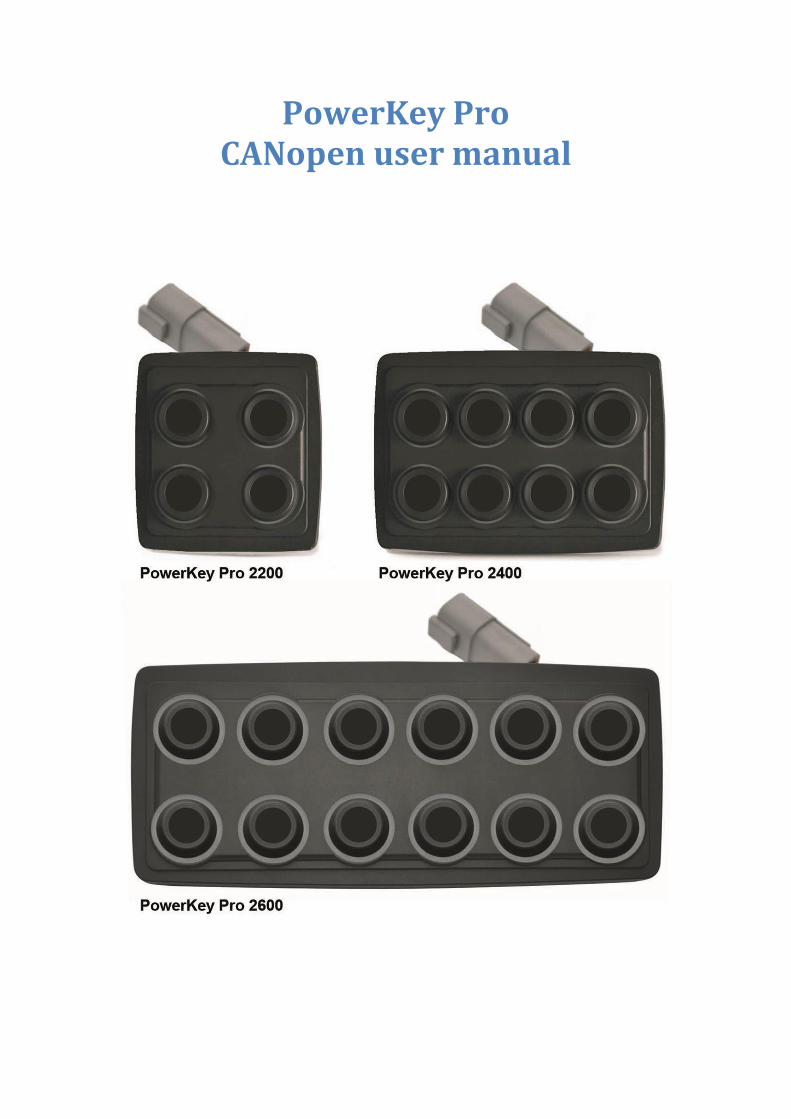
PowerKey Pro CANopen user manual
www.blinkmarine.com PKPCANopenUM_REV1.4 2/37
Summary: 1. How to connect Deutsch 4 pin: ............................................................................................................................ 4
2. Reference .............................................................................................................................................................. 4
3. Default settings ..................................................................................................................................................... 5
NMT MESSAGES ............................................................................................................................................................. 5
4. Start CANopen node (keypad activation message) .............................................................................................. 5
5. Enter pre-operational ........................................................................................................................................... 5
6. Reset CANopen node ............................................................................................................................................ 6
7. Stop CANopen node ............................................................................................................................................. 6
8. Boot-up service ..................................................................................................................................................... 6
9. Heartbeat message ............................................................................................................................................... 7
PDO messages ................................................................................................................................................................ 8
10. Keys status message ............................................................................................................................................. 8
PKP 2200 ............................................................................................................................................................ 8
PKP 2400 ............................................................................................................................................................ 8
PKP 2600 ............................................................................................................................................................ 8
11. Set LED ON message ............................................................................................................................................. 9
PKP 2200 ............................................................................................................................................................ 9
PKP 2400 ............................................................................................................................................................ 9
PKP 2600 ............................................................................................................................................................ 9
12. Set LED Blink message ........................................................................................................................................ 10
PKP 2200 .......................................................................................................................................................... 10
PKP 2400 .......................................................................................................................................................... 10
PKP 2600 .......................................................................................................................................................... 10
SDO Messages: ............................................................................................................................................................. 11
13. Object 6500h: Command Module ...................................................................................................................... 11
a) Set single LED state: 01h .................................................................................................................................. 11
b) Set LED brightness level: 02h ........................................................................................................................... 11
c) Set backlight brightness level: 03h .................................................................................................................. 12
d) Set device active on startup: 10h..................................................................................................................... 12
e) Set device baud rate: 11h ................................................................................................................................ 12
f) Set periodic transmission: 12h......................................................................................................................... 13
g) Set Boot-up service: 13h .................................................................................................................................. 13
h) Set CANopen node ID: 70h .............................................................................................................................. 13
i) Set default startup LED light level: 7Ch ........................................................................................................... 14
j) Set default startup backlight level: 7Bh ........................................................................................................... 14
k) Set DEMO mode: 7Ah ...................................................................................................................................... 14
l) Set startup LED show: 50h ............................................................................................................................... 15
14. Object 6000h: Digital input module, keys states ................................................................................................ 16
PKP 2200 .......................................................................................................................................................... 16
PKP 2400 .......................................................................................................................................................... 16
PKP 2600 .......................................................................................................................................................... 17
3/37 PKPCANopenUM_REV1.4 www.blinkmarine.com
15. Object 6001h: Digital output module. ................................................................................................................ 18
a) Set LED ON .......................................................................................................................................................... 18
PKP 2200 .......................................................................................................................................................... 18
PKP 2400 .......................................................................................................................................................... 18
PKP 2600 .......................................................................................................................................................... 19
b) Read LED ON ....................................................................................................................................................... 19
PKP2200 ........................................................................................................................................................... 19
PKP 2400 .......................................................................................................................................................... 20
PKP 2600 .......................................................................................................................................................... 20
16. Object 6002h: Digital output module. ................................................................................................................ 21
a) Set LED blink ....................................................................................................................................................... 21
PKP 2200 .......................................................................................................................................................... 21
PKP 2400 .......................................................................................................................................................... 21
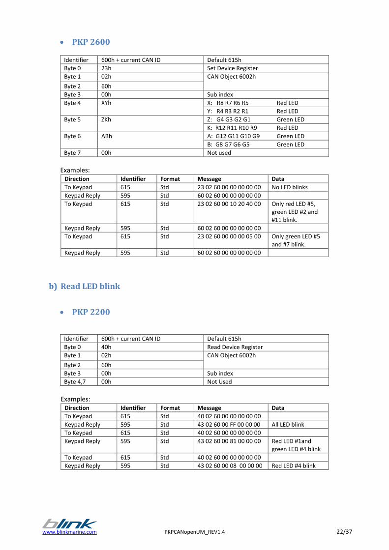
PKP 2600 .......................................................................................................................................................... 22
b) Read LED blink .................................................................................................................................................... 22
PKP 2200 .......................................................................................................................................................... 22
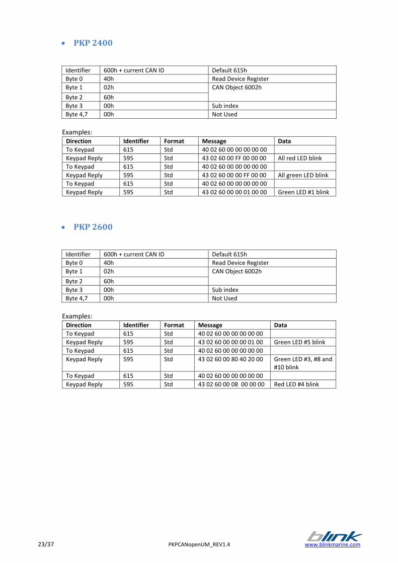
PKP 2400 .......................................................................................................................................................... 23
PKP 2600 .......................................................................................................................................................... 23
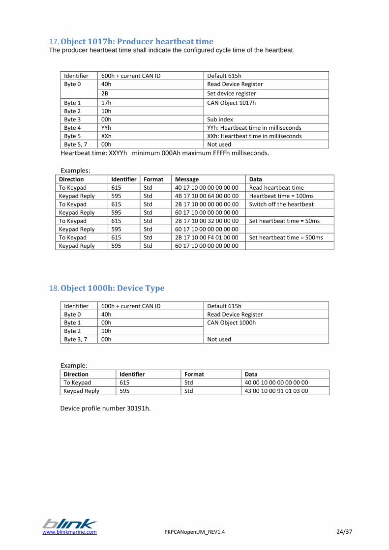
17. Object 1017h: Producer heartbeat time ............................................................................................................ 24
18. Object 1000h: Device Type ................................................................................................................................. 24
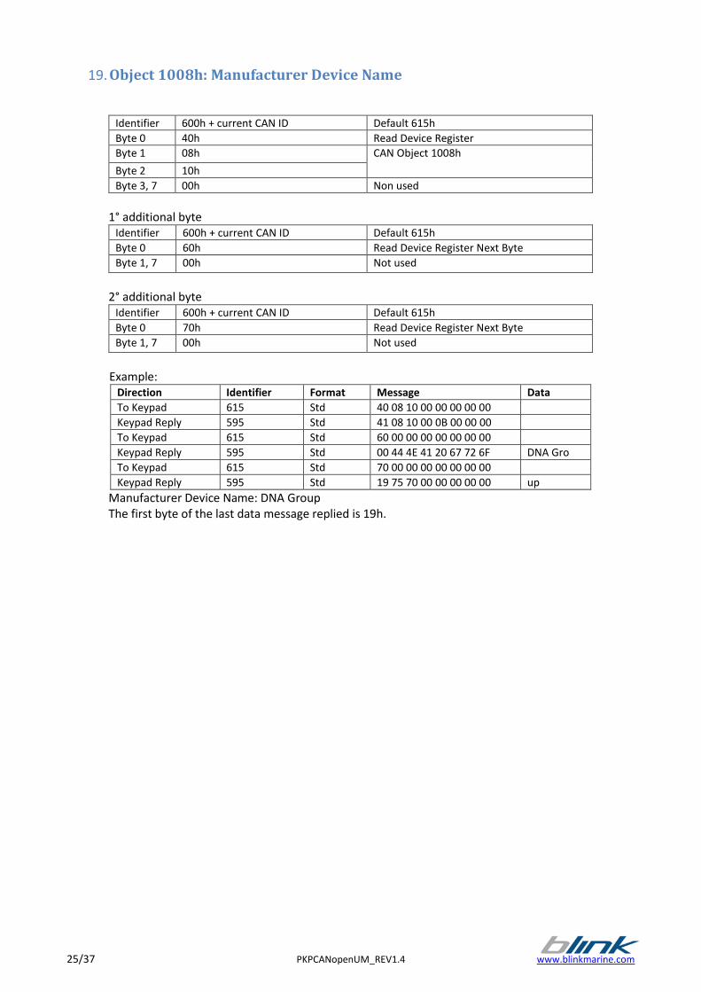
19. Object 1008h: Manufacturer Device Name ........................................................................................................ 25
20. Object 1009h: Manufacturer Hardware Revision ............................................................................................... 26
21. Object 100Ah: Manufacturer Firmware Revision ............................................................................................... 27
22. Object 100Bh: Model ID ..................................................................................................................................... 27
23. Object 1018h: Identity Data ............................................................................................................................... 28
24. Object 1400h: Receive PDO Communication Parm 0 ......................................................................................... 30
25. Object 1401h: Receive PDO communication Parm 1.......................................................................................... 30
26. Object 1600h: Output Descriptions .................................................................................................................... 31
27. Object 1800h: Transmit PDO Communication Parm 0 ....................................................................................... 32
28. Object 1A00h: Inputs description ....................................................................................................................... 32
29. Object 6100h: Device firmware specific ............................................................................................................. 33
30. Object 6201: Device brightness control.............................................................................................................. 34
a) Read brightness level ....................................................................................................................................... 34
b) Set brightness level .......................................................................................................................................... 34
31. Object 6300h: Serial number string ................................................................................................................... 35
32. Object 6301h: Bootloader presence ................................................................................................................... 35
33. Object 6302h: Device key and LED count ........................................................................................................... 36
www.blinkmarine.com PKPCANopenUM_REV1.4 4/37
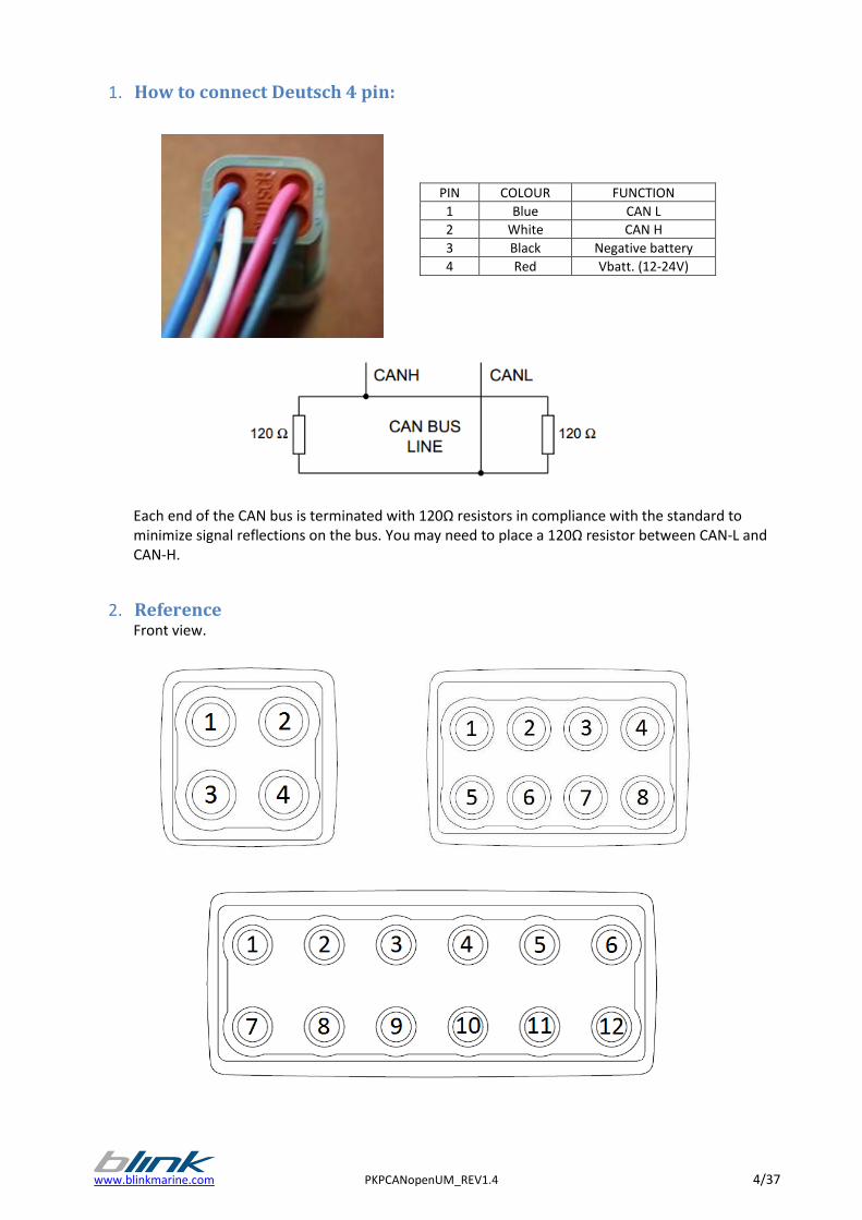
1. How to connect Deutsch 4 pin:
Each end of the CAN bus is terminated with 120Ω resistors in compliance with the standard to minimize signal reflections on the bus. You may need to place a 120Ω resistor between CAN-L and CAN-H.
2. Reference Front view.
PIN COLOUR FUNCTION
1 Blue CAN L
2 White CAN H
3 Black Negative battery
4 Red Vbatt. (12-24V)
5/37 PKPCANopenUM_REV1.4 www.blinkmarine.com
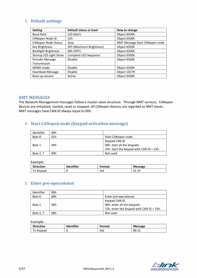
3. Default settings
Setting Default status or level How to change
Baud Rate 125 kbit/s Object 6500h
CANopen Node ID 15h Object 6500h
CANopen Node Status Stop NMT Message Start CANopen node
Key Brightness 3Fh (Maximum Brightness) Object 6500h
Backlight Brightness 00h (OFF) Object 6500h
Startup LED Light Show Complete LED Sequence Object 6500h
Periodic Message Transmission
Disable Object 6500h
DEMO mode Disable Object 6500h
Heartbeat Message Disable Object 1017h
Boot-up service Active Object 6500h
NMT MESSAGES The Network Management messages follow a master-slave structure. Through NMT services, CANopen devices are initialized, started, reset or stopped. All CANopen devices are regarded as NMT slaves. NMT messages have CAN-ID always equal to 00h.
4. Start CANopen node (keypad activation message)
Identifier 00h
Byte 0 01h Start CANopen node
Byte 1
XXh
Keypad CAN ID 00h: start all the keypads 15h: start the keypad with CAN ID = 15h.
Byte 2, 7 00h Not used
Example:
Direction Identifier Format Message
To Keypad 0 Std 01 15
5. Enter pre-operational
Identifier 00h
Byte 0 80h Enter pre-operational
Byte 1
XXh
Keypad CAN ID 00h: enter all the keypads 15h: enter the keypad with CAN ID = 15h.
Byte 2, 7 00h Not used
Example:
Direction Identifier Format Message
To Keypad 0 Std 80 15
www.blinkmarine.com PKPCANopenUM_REV1.4 6/37
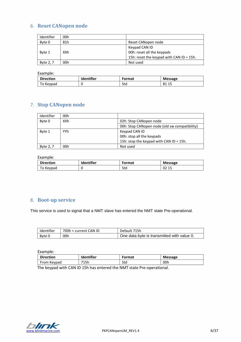
6. Reset CANopen node
Identifier 00h
Byte 0 81h Reset CANopen node
Byte 1
XXh
Keypad CAN ID 00h: reset all the keypads 15h: reset the keypad with CAN ID = 15h.
Byte 2, 7 00h Not used
Example:
Direction Identifier Format Message
To Keypad 0 Std 81 15
7. Stop CANopen node
Identifier 00h
Byte 0 XXh 02h: Stop CANopen node
00h: Stop CANopen node (old sw compatibility)
Byte 1 YYh Keypad CAN ID 00h: stop all the keypads 15h: stop the keypad with CAN ID = 15h.
Byte 2, 7 00h Not used
Example:
Direction Identifier Format Message
To Keypad 0 Std 02 15
8. Boot-up service
This service is used to signal that a NMT slave has entered the NMT state Pre-operational.
Identifier 700h + current CAN ID Default 715h
Byte 0 00h One data byte is transmitted with value 0.
Example: Direction Identifier Format Message
From Keypad 715h Std 00h
The keypad with CAN ID 15h has entered the NMT state Pre-operational.
7/37 PKPCANopenUM_REV1.4 www.blinkmarine.com
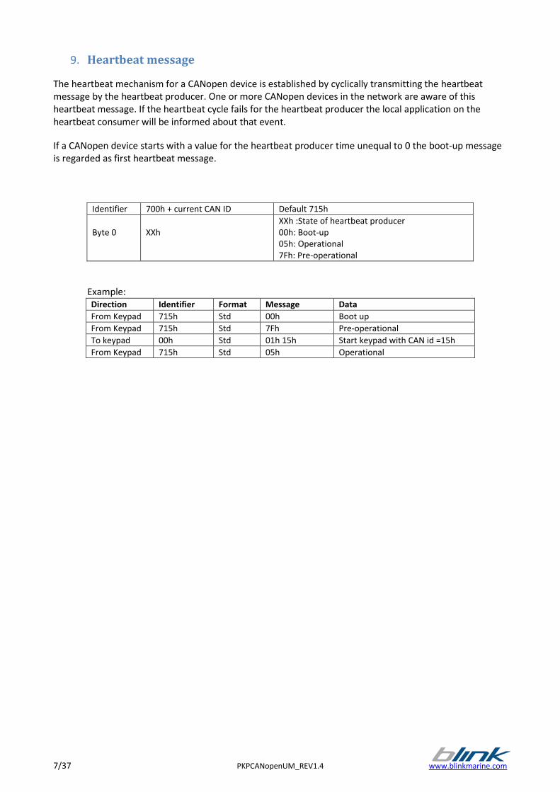
9. Heartbeat message
The heartbeat mechanism for a CANopen device is established by cyclically transmitting the heartbeat message by the heartbeat producer. One or more CANopen devices in the network are aware of this heartbeat message. If the heartbeat cycle fails for the heartbeat producer the local application on the heartbeat consumer will be informed about that event.
If a CANopen device starts with a value for the heartbeat producer time unequal to 0 the boot-up message is regarded as first heartbeat message.
Identifier 700h + current CAN ID Default 715h
Byte 0
XXh
XXh :State of heartbeat producer 00h: Boot-up 05h: Operational 7Fh: Pre-operational
Example: Direction Identifier Format Message Data
From Keypad 715h Std 00h Boot up
From Keypad 715h Std 7Fh Pre-operational
To keypad 00h Std 01h 15h Start keypad with CAN id =15h
From Keypad 715h Std 05h Operational
www.blinkmarine.com PKPCANopenUM_REV1.4 8/37
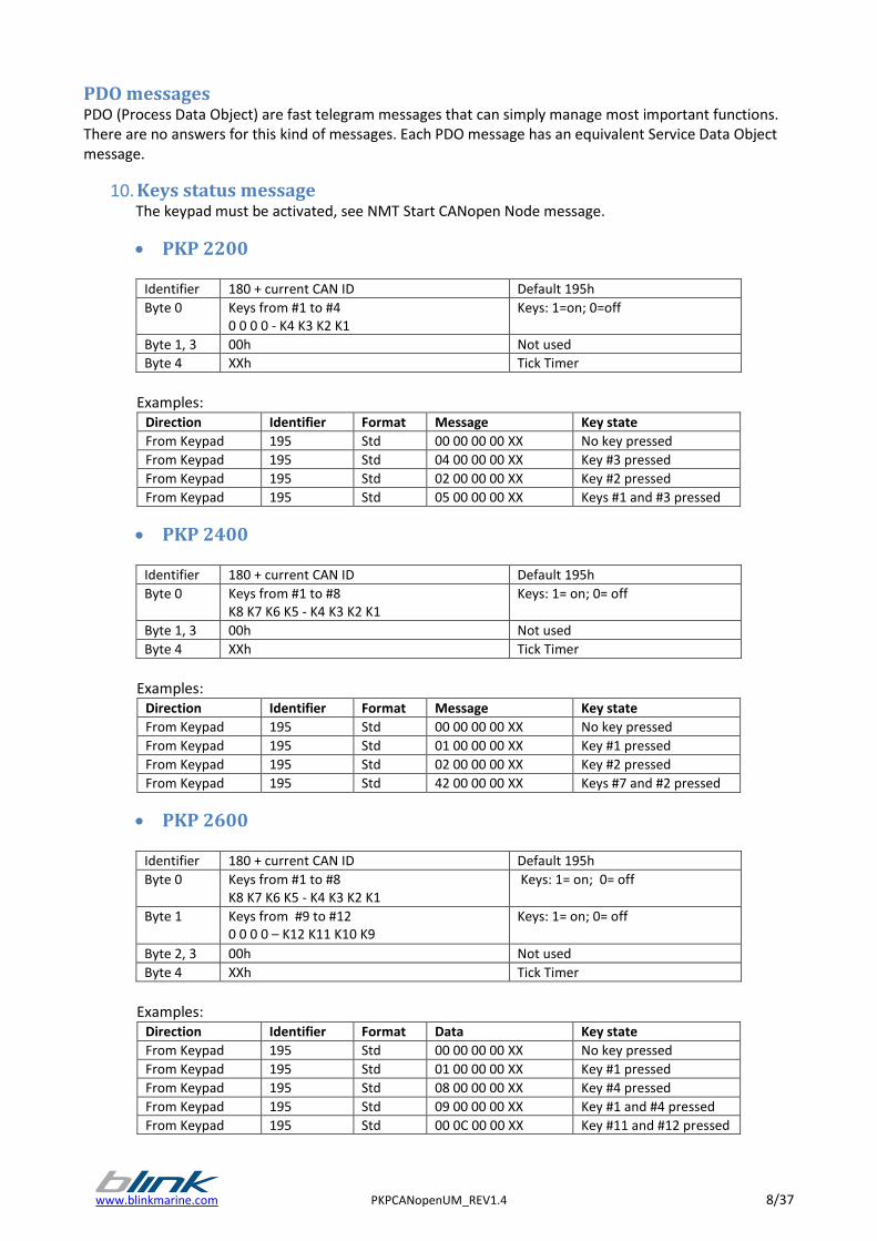
PDO messages PDO (Process Data Object) are fast telegram messages that can simply manage most important functions. There are no answers for this kind of messages. Each PDO message has an equivalent Service Data Object message.
10. Keys status message The keypad must be activated, see NMT Start CANopen Node message.
PKP 2200
Identifier 180 + current CAN ID Default 195h
Byte 0 Keys from #1 to #4 0 0 0 0 - K4 K3 K2 K1
Keys: 1=on; 0=off
Byte 1, 3 00h Not used
Byte 4 XXh Tick Timer
Examples:
Direction Identifier Format Message Key state
From Keypad 195 Std 00 00 00 00 XX No key pressed
From Keypad 195 Std 04 00 00 00 XX Key #3 pressed
From Keypad 195 Std 02 00 00 00 XX Key #2 pressed
From Keypad 195 Std 05 00 00 00 XX Keys #1 and #3 pressed
PKP 2400
Identifier 180 + current CAN ID Default 195h
Byte 0 Keys from #1 to #8 K8 K7 K6 K5 - K4 K3 K2 K1
Keys: 1= on; 0= off
Byte 1, 3 00h Not used
Byte 4 XXh Tick Timer
Examples:
Direction Identifier Format Message Key state
From Keypad 195 Std 00 00 00 00 XX No key pressed
From Keypad 195 Std 01 00 00 00 XX Key #1 pressed
From Keypad 195 Std 02 00 00 00 XX Key #2 pressed
From Keypad 195 Std 42 00 00 00 XX Keys #7 and #2 pressed
PKP 2600
Identifier 180 + current CAN ID Default 195h
Byte 0 Keys from #1 to #8 K8 K7 K6 K5 - K4 K3 K2 K1
Keys: 1= on; 0= off
Byte 1 Keys from #9 to #12 0 0 0 0 – K12 K11 K10 K9
Keys: 1= on; 0= off
Byte 2, 3 00h Not used
Byte 4 XXh Tick Timer
Examples:
Direction Identifier Format Data Key state
From Keypad 195 Std 00 00 00 00 XX No key pressed
From Keypad 195 Std 01 00 00 00 XX Key #1 pressed
From Keypad 195 Std 08 00 00 00 XX Key #4 pressed
From Keypad 195 Std 09 00 00 00 XX Key #1 and #4 pressed
From Keypad 195 Std 00 0C 00 00 XX Key #11 and #12 pressed
9/37 PKPCANopenUM_REV1.4 www.blinkmarine.com
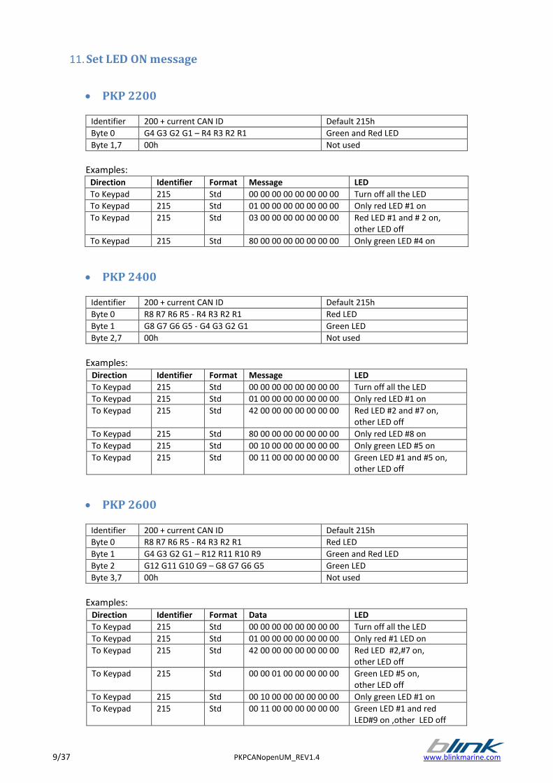
11. Set LED ON message
PKP 2200
Identifier 200 + current CAN ID Default 215h
Byte 0 G4 G3 G2 G1 – R4 R3 R2 R1 Green and Red LED
Byte 1,7 00h Not used
Examples:
Direction Identifier Format Message LED
To Keypad 215 Std 00 00 00 00 00 00 00 00 Turn off all the LED
To Keypad 215 Std 01 00 00 00 00 00 00 00 Only red LED #1 on
To Keypad 215 Std 03 00 00 00 00 00 00 00 Red LED #1 and # 2 on, other LED off
To Keypad 215 Std 80 00 00 00 00 00 00 00 Only green LED #4 on
PKP 2400
Identifier 200 + current CAN ID Default 215h
Byte 0 R8 R7 R6 R5 - R4 R3 R2 R1 Red LED
Byte 1 G8 G7 G6 G5 - G4 G3 G2 G1 Green LED
Byte 2,7 00h Not used
Examples:
Direction Identifier Format Message LED
To Keypad 215 Std 00 00 00 00 00 00 00 00 Turn off all the LED
To Keypad 215 Std 01 00 00 00 00 00 00 00 Only red LED #1 on
To Keypad 215 Std 42 00 00 00 00 00 00 00 Red LED #2 and #7 on, other LED off
To Keypad 215 Std 80 00 00 00 00 00 00 00 Only red LED #8 on
To Keypad 215 Std 00 10 00 00 00 00 00 00 Only green LED #5 on
To Keypad 215 Std 00 11 00 00 00 00 00 00 Green LED #1 and #5 on, other LED off
PKP 2600
Identifier 200 + current CAN ID Default 215h
Byte 0 R8 R7 R6 R5 - R4 R3 R2 R1 Red LED
Byte 1 G4 G3 G2 G1 – R12 R11 R10 R9 Green and Red LED
Byte 2 G12 G11 G10 G9 – G8 G7 G6 G5 Green LED
Byte 3,7 00h Not used
Examples:
Direction Identifier Format Data LED
To Keypad 215 Std 00 00 00 00 00 00 00 00 Turn off all the LED
To Keypad 215 Std 01 00 00 00 00 00 00 00 Only red #1 LED on
To Keypad 215 Std 42 00 00 00 00 00 00 00 Red LED #2,#7 on, other LED off
To Keypad 215 Std 00 00 01 00 00 00 00 00 Green LED #5 on, other LED off
To Keypad 215 Std 00 10 00 00 00 00 00 00 Only green LED #1 on
To Keypad 215 Std 00 11 00 00 00 00 00 00 Green LED #1 and red LED#9 on ,other LED off
www.blinkmarine.com PKPCANopenUM_REV1.4 10/37
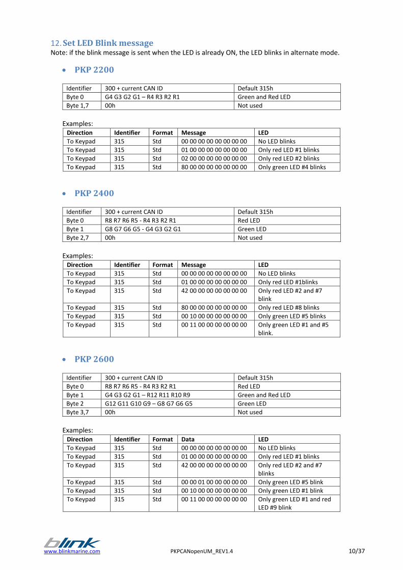
12. Set LED Blink message Note: if the blink message is sent when the LED is already ON, the LED blinks in alternate mode.
PKP 2200
Identifier 300 + current CAN ID Default 315h
Byte 0 G4 G3 G2 G1 – R4 R3 R2 R1 Green and Red LED
Byte 1,7 00h Not used
Examples:
Direction Identifier Format Message LED
To Keypad 315 Std 00 00 00 00 00 00 00 00 No LED blinks
To Keypad 315 Std 01 00 00 00 00 00 00 00 Only red LED #1 blinks
To Keypad 315 Std 02 00 00 00 00 00 00 00 Only red LED #2 blinks
To Keypad 315 Std 80 00 00 00 00 00 00 00 Only green LED #4 blinks
PKP 2400
Identifier 300 + current CAN ID Default 315h
Byte 0 R8 R7 R6 R5 - R4 R3 R2 R1 Red LED
Byte 1 G8 G7 G6 G5 - G4 G3 G2 G1 Green LED
Byte 2,7 00h Not used
Examples:
Direction Identifier Format Message LED
To Keypad 315 Std 00 00 00 00 00 00 00 00 No LED blinks
To Keypad 315 Std 01 00 00 00 00 00 00 00 Only red LED #1blinks
To Keypad 315 Std 42 00 00 00 00 00 00 00 Only red LED #2 and #7 blink
To Keypad 315 Std 80 00 00 00 00 00 00 00 Only red LED #8 blinks
To Keypad 315 Std 00 10 00 00 00 00 00 00 Only green LED #5 blinks
To Keypad 315 Std 00 11 00 00 00 00 00 00 Only green LED #1 and #5 blink.
PKP 2600
Identifier 300 + current CAN ID Default 315h
Byte 0 R8 R7 R6 R5 - R4 R3 R2 R1 Red LED
Byte 1 G4 G3 G2 G1 – R12 R11 R10 R9 Green and Red LED
Byte 2 G12 G11 G10 G9 – G8 G7 G6 G5 Green LED
Byte 3,7 00h Not used
Examples:
Direction Identifier Format Data LED
To Keypad 315 Std 00 00 00 00 00 00 00 00 No LED blinks
To Keypad 315 Std 01 00 00 00 00 00 00 00 Only red LED #1 blinks
To Keypad 315 Std 42 00 00 00 00 00 00 00 Only red LED #2 and #7 blinks
To Keypad 315 Std 00 00 01 00 00 00 00 00 Only green LED #5 blink
To Keypad 315 Std 00 10 00 00 00 00 00 00 Only green LED #1 blink
To Keypad 315 Std 00 11 00 00 00 00 00 00 Only green LED #1 and red LED #9 blink
11/37 PKPCANopenUM_REV1.4 www.blinkmarine.com
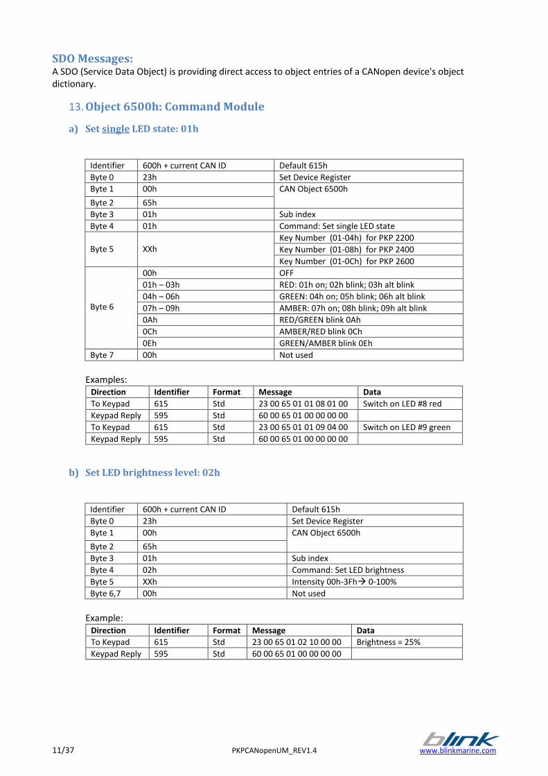
SDO Messages: A SDO (Service Data Object) is providing direct access to object entries of a CANopen device's object dictionary.
13. Object 6500h: Command Module
a) Set single LED state: 01h
Identifier 600h + current CAN ID Default 615h
Byte 0 23h Set Device Register
Byte 1 00h CAN Object 6500h
Byte 2 65h
Byte 3 01h Sub index
Byte 4 01h Command: Set single LED state
Byte 5
XXh
Key Number (01-04h) for PKP 2200
Key Number (01-08h) for PKP 2400
Key Number (01-0Ch) for PKP 2600
Byte 6
00h OFF
01h – 03h RED: 01h on; 02h blink; 03h alt blink
04h – 06h GREEN: 04h on; 05h blink; 06h alt blink
07h – 09h AMBER: 07h on; 08h blink; 09h alt blink
0Ah RED/GREEN blink 0Ah
0Ch AMBER/RED blink 0Ch
0Eh GREEN/AMBER blink 0Eh
Byte 7 00h Not used
Examples:
Direction Identifier Format Message Data
To Keypad 615 Std 23 00 65 01 01 08 01 00 Switch on LED #8 red
Keypad Reply 595 Std 60 00 65 01 00 00 00 00
To Keypad 615 Std 23 00 65 01 01 09 04 00 Switch on LED #9 green
Keypad Reply 595 Std 60 00 65 01 00 00 00 00
b) Set LED brightness level: 02h
Identifier 600h + current CAN ID Default 615h
Byte 0 23h Set Device Register
Byte 1 00h CAN Object 6500h
Byte 2 65h
Byte 3 01h Sub index
Byte 4 02h Command: Set LED brightness
Byte 5 XXh Intensity 00h-3Fh 0-100%
Byte 6,7 00h Not used
Example:
Direction Identifier Format Message Data
To Keypad 615 Std 23 00 65 01 02 10 00 00 Brightness = 25%
Keypad Reply 595 Std 60 00 65 01 00 00 00 00
www.blinkmarine.com PKPCANopenUM_REV1.4 12/37
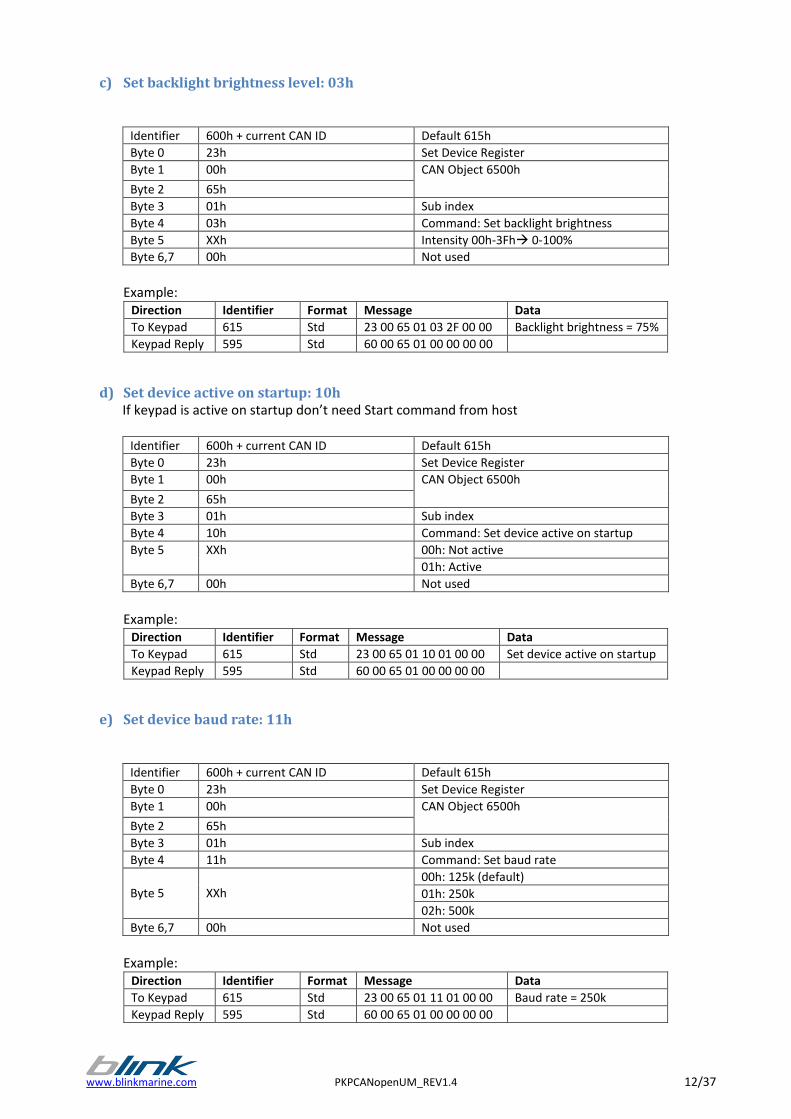
c) Set backlight brightness level: 03h
Identifier 600h + current CAN ID Default 615h
Byte 0 23h Set Device Register
Byte 1 00h CAN Object 6500h
Byte 2 65h
Byte 3 01h Sub index
Byte 4 03h Command: Set backlight brightness
Byte 5 XXh Intensity 00h-3Fh 0-100%
Byte 6,7 00h Not used
Example:
Direction Identifier Format Message Data
To Keypad 615 Std 23 00 65 01 03 2F 00 00 Backlight brightness = 75%
Keypad Reply 595 Std 60 00 65 01 00 00 00 00
d) Set device active on startup: 10h If keypad is active on startup don’t need Start command from host
Identifier 600h + current CAN ID Default 615h
Byte 0 23h Set Device Register
Byte 1 00h CAN Object 6500h
Byte 2 65h
Byte 3 01h Sub index
Byte 4 10h Command: Set device active on startup
Byte 5 XXh 00h: Not active
01h: Active
Byte 6,7 00h Not used
Example:
Direction Identifier Format Message Data
To Keypad 615 Std 23 00 65 01 10 01 00 00 Set device active on startup
Keypad Reply 595 Std 60 00 65 01 00 00 00 00
e) Set device baud rate: 11h
Identifier 600h + current CAN ID Default 615h
Byte 0 23h Set Device Register
Byte 1 00h CAN Object 6500h
Byte 2 65h
Byte 3 01h Sub index
Byte 4 11h Command: Set baud rate
Byte 5
XXh
00h: 125k (default)
01h: 250k
02h: 500k
Byte 6,7 00h Not used
Example:
Direction Identifier Format Message Data
To Keypad 615 Std 23 00 65 01 11 01 00 00 Baud rate = 250k
Keypad Reply 595 Std 60 00 65 01 00 00 00 00
13/37 PKPCANopenUM_REV1.4 www.blinkmarine.com
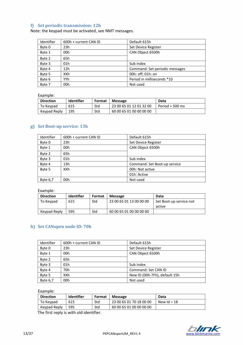
f) Set periodic transmission: 12h Note: the keypad must be activated, see NMT messages.
Identifier 600h + current CAN ID Default 615h
Byte 0 23h Set Device Register
Byte 1 00h CAN Object 6500h
Byte 2 65h
Byte 3 01h Sub index
Byte 4 12h Command: Set periodic messages
Byte 5 XXh 00h: off; 01h: on
Byte 6 YYh Period in milliseconds *10
Byte 7 00h Not used
Example:
Direction Identifier Format Message Data
To Keypad 615 Std 23 00 65 01 12 01 32 00 Period = 500 ms
Keypad Reply 195 Std 60 00 65 01 00 00 00 00
g) Set Boot-up service: 13h
Identifier 600h + current CAN ID Default 615h
Byte 0 23h Set Device Register
Byte 1 00h CAN Object 6500h
Byte 2 65h
Byte 3 01h Sub index
Byte 4 13h Command: Set Boot-up service
Byte 5 XXh 00h: Not active
01h: Active
Byte 6,7 00h Not used
Example:
Direction Identifier Format Message Data
To Keypad 615 Std 23 00 65 01 13 00 00 00 Set Boot-up service not active
Keypad Reply 595 Std 60 00 65 01 00 00 00 00
h) Set CANopen node ID: 70h
Identifier 600h + current CAN ID Default 615h
Byte 0 23h Set Device Register
Byte 1 00h CAN Object 6500h
Byte 2 65h
Byte 3 01h Sub index
Byte 4 70h Command: Set CAN ID
Byte 5 XXh New ID (00h-7Fh), default 15h
Byte 6,7 00h Not used
Example:
Direction Identifier Format Message Data
To Keypad 615 Std 23 00 65 01 70 18 00 00 New Id = 18
Keypad Reply 595 Std 60 00 65 01 00 00 00 00
The first reply is with old identifier.
www.blinkmarine.com PKPCANopenUM_REV1.4 14/37
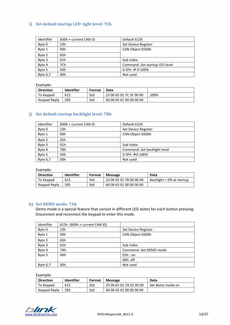
i) Set default startup LED light level: 7Ch
Identifier 600h + current CAN ID Default 615h
Byte 0 23h Set Device Register
Byte 1 00h CAN Object 6500h
Byte 2 65h
Byte 3 01h Sub index
Byte 4 7Ch Command: Set startup LED level
Byte 5 XXh 0-3Fh 0-100%
Byte 6,7 00h Not used
Example:
Direction Identifier Format Data
To Keypad 615 Std 23 00 65 01 7C 3F 00 00 100%
Keypad Reply 595 Std 60 00 65 01 00 00 00 00
j) Set default startup backlight level: 7Bh
Identifier 600h + current CAN ID Default 615h
Byte 0 23h Set Device Register
Byte 1 00h CAN Object 6500h
Byte 2 65h
Byte 3 01h Sub index
Byte 4 7Bh Command: Set backlight level
Byte 5 XXh 0-3Fh 0-100%
Byte 6,7 00h Not used
Example:
Direction Identifier Format Message Data
To Keypad 615 Std 23 00 65 01 7B 00 00 00 Backlight = 0% at startup
Keypad Reply 595 Std 60 00 65 01 00 00 00 00
k) Set DEMO mode: 7Ah Demo mode is a special feature that consist in different LED states for each button pressing.
Disconnect and reconnect the keypad to enter this mode.
Identifier 615h (600h + current CAN ID)
Byte 0 23h Set Device Register
Byte 1 00h CAN Object 6500h
Byte 2 65h
Byte 3 01h Sub index
Byte 4 7Ah Command: Set DEMO mode
Byte 5 XXh 01h : on
00h: off
Byte 6,7 00h Not used
Example:
Direction Identifier Format Message Data
To Keypad 615 Std 23 00 65 01 7A 01 00 00 Set demo mode on
Keypad Reply 595 Std 60 00 65 01 00 00 00 00
15/37 PKPCANopenUM_REV1.4 www.blinkmarine.com
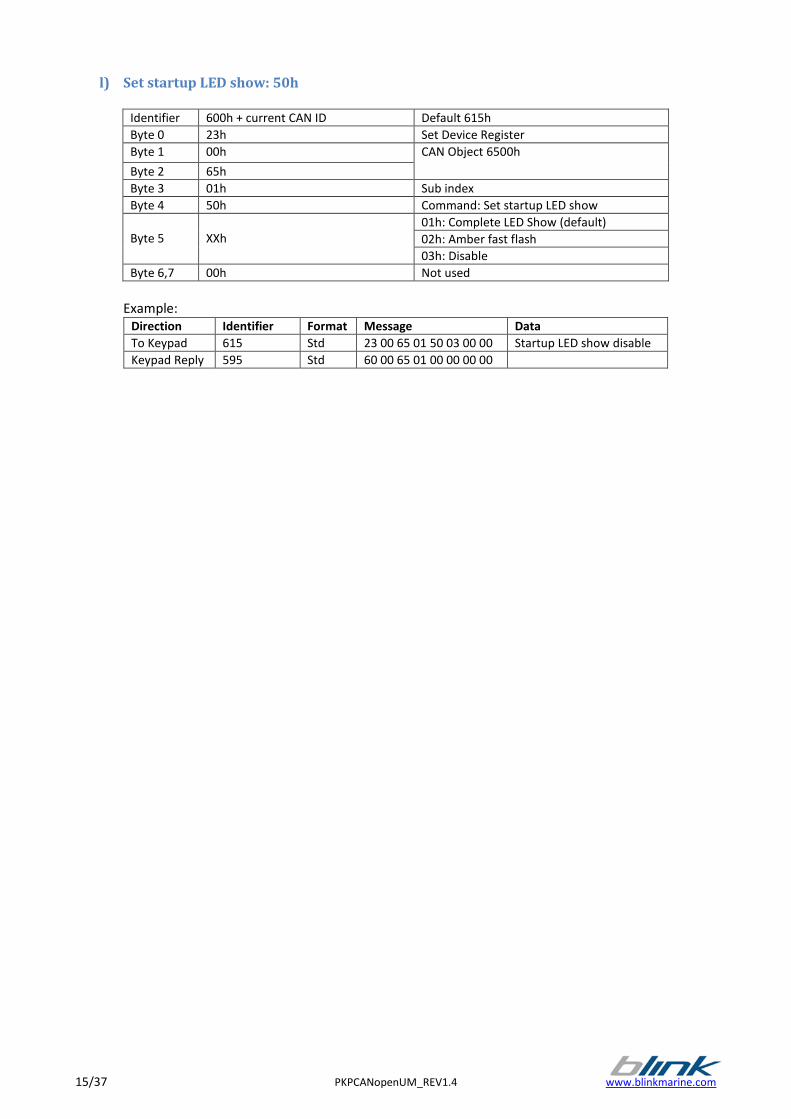
l) Set startup LED show: 50h
Identifier 600h + current CAN ID Default 615h
Byte 0 23h Set Device Register
Byte 1 00h CAN Object 6500h
Byte 2 65h
Byte 3 01h Sub index
Byte 4 50h Command: Set startup LED show
Byte 5
XXh
01h: Complete LED Show (default)
02h: Amber fast flash
03h: Disable
Byte 6,7 00h Not used
Example:
Direction Identifier Format Message Data
To Keypad 615 Std 23 00 65 01 50 03 00 00 Startup LED show disable
Keypad Reply 595 Std 60 00 65 01 00 00 00 00
www.blinkmarine.com PKPCANopenUM_REV1.4 16/37
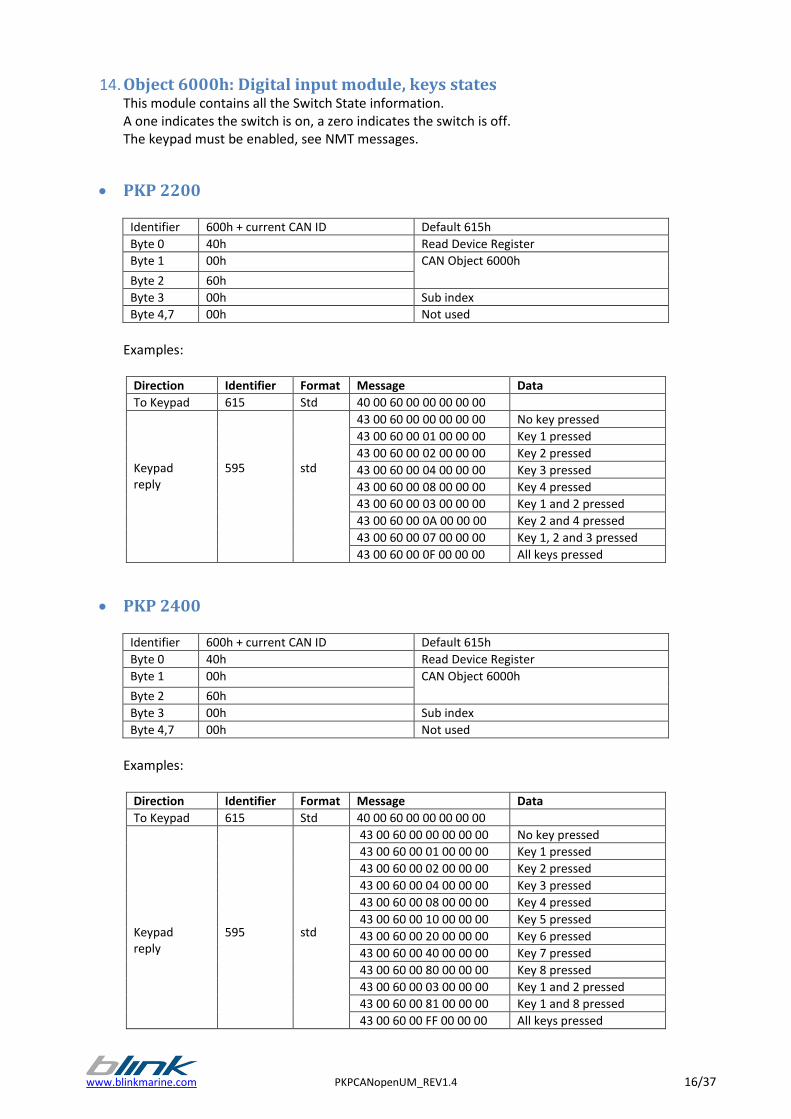
14. Object 6000h: Digital input module, keys states This module contains all the Switch State information. A one indicates the switch is on, a zero indicates the switch is off. The keypad must be enabled, see NMT messages.
PKP 2200
Identifier 600h + current CAN ID Default 615h
Byte 0 40h Read Device Register
Byte 1 00h CAN Object 6000h
Byte 2 60h
Byte 3 00h Sub index
Byte 4,7 00h Not used
Examples:
Direction Identifier Format Message Data
To Keypad 615 Std 40 00 60 00 00 00 00 00
Keypad reply
595
std
43 00 60 00 00 00 00 00 No key pressed
43 00 60 00 01 00 00 00 Key 1 pressed
43 00 60 00 02 00 00 00 Key 2 pressed
43 00 60 00 04 00 00 00 Key 3 pressed
43 00 60 00 08 00 00 00 Key 4 pressed
43 00 60 00 03 00 00 00 Key 1 and 2 pressed
43 00 60 00 0A 00 00 00 Key 2 and 4 pressed
43 00 60 00 07 00 00 00 Key 1, 2 and 3 pressed
43 00 60 00 0F 00 00 00 All keys pressed
PKP 2400
Identifier 600h + current CAN ID Default 615h
Byte 0 40h Read Device Register
Byte 1 00h CAN Object 6000h
Byte 2 60h
Byte 3 00h Sub index
Byte 4,7 00h Not used
Examples:
Direction Identifier Format Message Data
To Keypad 615 Std 40 00 60 00 00 00 00 00
Keypad reply
595
std
43 00 60 00 00 00 00 00 No key pressed
43 00 60 00 01 00 00 00 Key 1 pressed
43 00 60 00 02 00 00 00 Key 2 pressed
43 00 60 00 04 00 00 00 Key 3 pressed
43 00 60 00 08 00 00 00 Key 4 pressed
43 00 60 00 10 00 00 00 Key 5 pressed
43 00 60 00 20 00 00 00 Key 6 pressed
43 00 60 00 40 00 00 00 Key 7 pressed
43 00 60 00 80 00 00 00 Key 8 pressed
43 00 60 00 03 00 00 00 Key 1 and 2 pressed
43 00 60 00 81 00 00 00 Key 1 and 8 pressed
43 00 60 00 FF 00 00 00 All keys pressed
17/37 PKPCANopenUM_REV1.4 www.blinkmarine.com
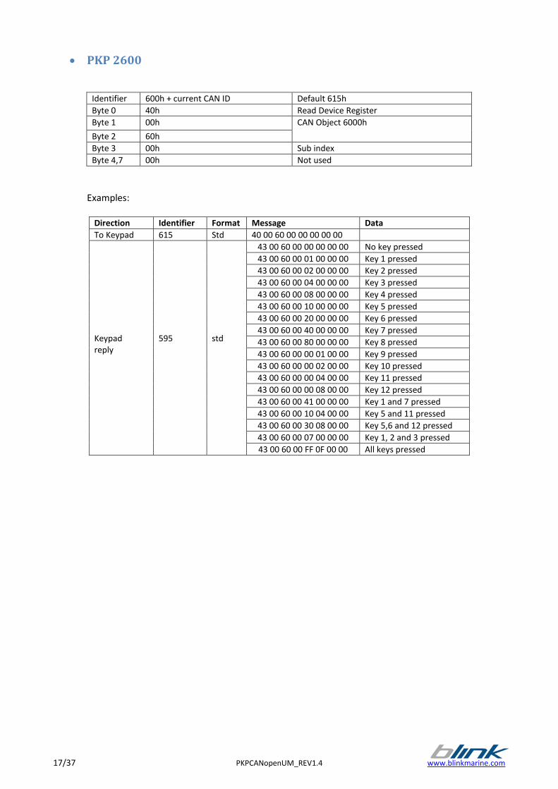
PKP 2600
Identifier 600h + current CAN ID Default 615h
Byte 0 40h Read Device Register
Byte 1 00h CAN Object 6000h
Byte 2 60h
Byte 3 00h Sub index
Byte 4,7 00h Not used
Examples:
Direction Identifier Format Message Data
To Keypad 615 Std 40 00 60 00 00 00 00 00
Keypad reply
595
std
43 00 60 00 00 00 00 00 No key pressed
43 00 60 00 01 00 00 00 Key 1 pressed
43 00 60 00 02 00 00 00 Key 2 pressed
43 00 60 00 04 00 00 00 Key 3 pressed
43 00 60 00 08 00 00 00 Key 4 pressed
43 00 60 00 10 00 00 00 Key 5 pressed
43 00 60 00 20 00 00 00 Key 6 pressed
43 00 60 00 40 00 00 00 Key 7 pressed
43 00 60 00 80 00 00 00 Key 8 pressed
43 00 60 00 00 01 00 00 Key 9 pressed
43 00 60 00 00 02 00 00 Key 10 pressed
43 00 60 00 00 04 00 00 Key 11 pressed
43 00 60 00 00 08 00 00 Key 12 pressed
43 00 60 00 41 00 00 00 Key 1 and 7 pressed
43 00 60 00 10 04 00 00 Key 5 and 11 pressed
43 00 60 00 30 08 00 00 Key 5,6 and 12 pressed
43 00 60 00 07 00 00 00 Key 1, 2 and 3 pressed
43 00 60 00 FF 0F 00 00 All keys pressed
www.blinkmarine.com PKPCANopenUM_REV1.4 18/37
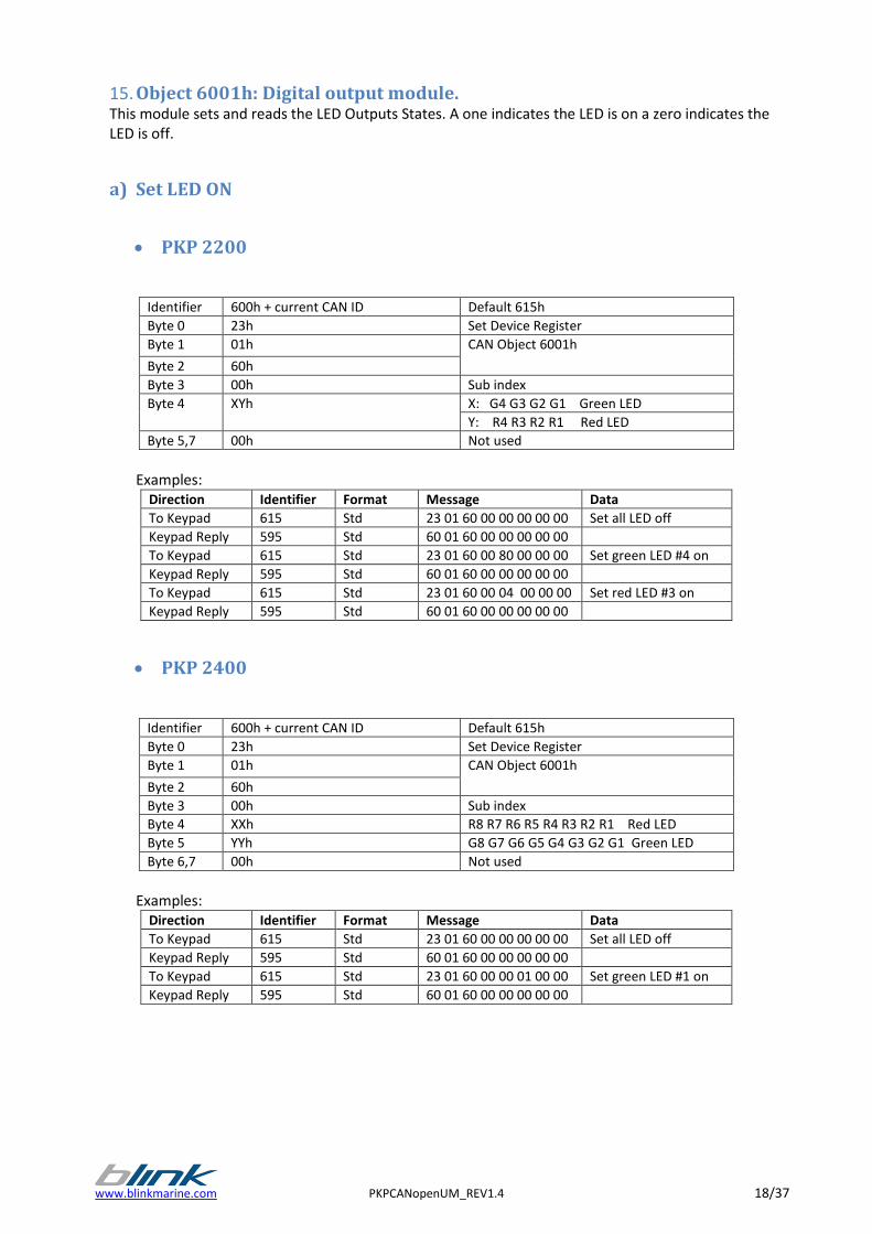
15. Object 6001h: Digital output module. This module sets and reads the LED Outputs States. A one indicates the LED is on a zero indicates the LED is off.
a) Set LED ON
PKP 2200
Identifier 600h + current CAN ID Default 615h
Byte 0 23h Set Device Register
Byte 1 01h CAN Object 6001h
Byte 2 60h
Byte 3 00h Sub index
Byte 4 XYh X: G4 G3 G2 G1 Green LED
Y: R4 R3 R2 R1 Red LED
Byte 5,7 00h Not used
Examples:
Direction Identifier Format Message Data
To Keypad 615 Std 23 01 60 00 00 00 00 00 Set all LED off
Keypad Reply 595 Std 60 01 60 00 00 00 00 00
To Keypad 615 Std 23 01 60 00 80 00 00 00 Set green LED #4 on
Keypad Reply 595 Std 60 01 60 00 00 00 00 00
To Keypad 615 Std 23 01 60 00 04 00 00 00 Set red LED #3 on
Keypad Reply 595 Std 60 01 60 00 00 00 00 00
PKP 2400
Identifier 600h + current CAN ID Default 615h
Byte 0 23h Set Device Register
Byte 1 01h CAN Object 6001h
Byte 2 60h
Byte 3 00h Sub index
Byte 4 XXh R8 R7 R6 R5 R4 R3 R2 R1 Red LED
Byte 5 YYh G8 G7 G6 G5 G4 G3 G2 G1 Green LED
Byte 6,7 00h Not used
Examples:
Direction Identifier Format Message Data
To Keypad 615 Std 23 01 60 00 00 00 00 00 Set all LED off
Keypad Reply 595 Std 60 01 60 00 00 00 00 00
To Keypad 615 Std 23 01 60 00 00 01 00 00 Set green LED #1 on
Keypad Reply 595 Std 60 01 60 00 00 00 00 00

19/37 PKPCANopenUM_REV1.4 www.blinkmarine.com
PKP 2600
Identifier 600h + current CAN ID Default 615h
Byte 0 23h Set Device Register
Byte 1 01h CAN Object 6001h
Byte 2 60h
Byte 3 00h Sub index
Byte 4 XYh X: R8 R7 R6 R5 Red LED
Y: R4 R3 R2 R1 Red LED
Byte 5 ZKh Z: G4 G3 G2 G1 Green LED
K: R12 R11 R10 R9 Red LED
Byte 6 ABh A: G12 G11 G10 G9 Green LED
B: G8 G7 G6 G5 Green LED
Byte 7 00h Not used
Examples:
Direction Identifier Format Message Data
To Keypad 615 Std 23 01 60 00 00 00 00 00 Set all LED off
Keypad Reply 595 Std 60 01 60 00 00 00 00 00
To Keypad 615 Std 23 01 60 00 80 00 00 00 Set red LED #8 on, other LED off
Keypad Reply 595 Std 60 01 60 00 00 00 00 00
To Keypad 615 Std 23 01 60 00 40 40 40 00 Set LED R7,G3,G11 on, other off
Keypad Reply 595 Std 60 01 60 00 00 00 00 00
b) Read LED ON The LEDs have the same mapping of Set LED ON message
PKP2200
Identifier 600h + current CAN ID Default 615h
Byte 0 40h Read Device Register
Byte 1 01h CAN Object 6001h
Byte 2 60h
Byte 3 00h Sub index
Byte 4,7 00h Not Used
Examples:
Direction Identifier Format Message Data
To Keypad 615 Std 40 01 60 00 00 00 00 00
Keypad Reply 595 Std 43 01 60 00 0F 00 00 00 All red LED on
To Keypad 615 Std 40 01 60 00 00 00 00 00
Keypad Reply 595 Std 43 01 60 00 08 00 00 00 Red LED #4 on
To Keypad 615 Std 40 01 60 00 00 00 00 00
Keypad Reply 595 Std 43 01 60 00 20 00 00 00 Green LED #2 on
To Keypad 615 Std 40 01 60 00 00 00 00 00
Keypad Reply 595 Std 43 01 60 00 00 F0 00 00 All green LED on
www.blinkmarine.com PKPCANopenUM_REV1.4 20/37
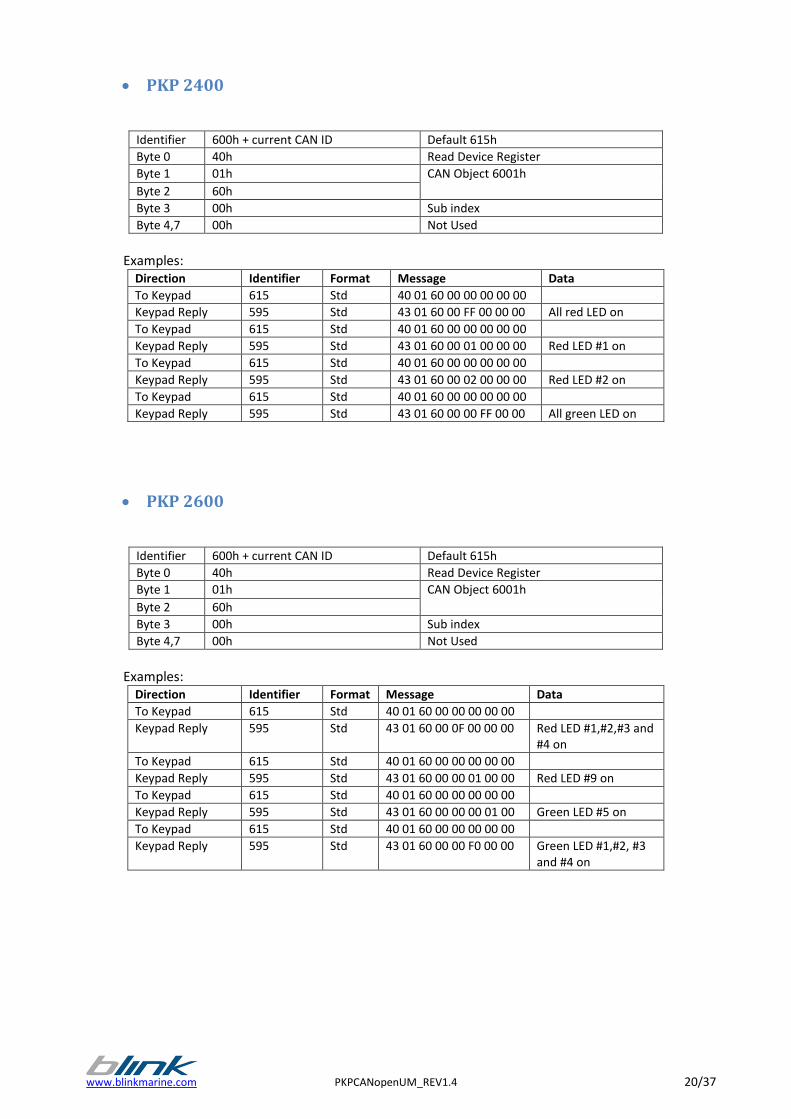
PKP 2400
Identifier 600h + current CAN ID Default 615h
Byte 0 40h Read Device Register
Byte 1 01h CAN Object 6001h
Byte 2 60h
Byte 3 00h Sub index
Byte 4,7 00h Not Used
Examples:
Direction Identifier Format Message Data
To Keypad 615 Std 40 01 60 00 00 00 00 00
Keypad Reply 595 Std 43 01 60 00 FF 00 00 00 All red LED on
To Keypad 615 Std 40 01 60 00 00 00 00 00
Keypad Reply 595 Std 43 01 60 00 01 00 00 00 Red LED #1 on
To Keypad 615 Std 40 01 60 00 00 00 00 00
Keypad Reply 595 Std 43 01 60 00 02 00 00 00 Red LED #2 on
To Keypad 615 Std 40 01 60 00 00 00 00 00
Keypad Reply 595 Std 43 01 60 00 00 FF 00 00 All green LED on
PKP 2600
Identifier 600h + current CAN ID Default 615h
Byte 0 40h Read Device Register
Byte 1 01h CAN Object 6001h
Byte 2 60h
Byte 3 00h Sub index
Byte 4,7 00h Not Used
Examples:
Direction Identifier Format Message Data
To Keypad 615 Std 40 01 60 00 00 00 00 00
Keypad Reply 595 Std 43 01 60 00 0F 00 00 00 Red LED #1,#2,#3 and #4 on
To Keypad 615 Std 40 01 60 00 00 00 00 00
Keypad Reply 595 Std 43 01 60 00 00 01 00 00 Red LED #9 on
To Keypad 615 Std 40 01 60 00 00 00 00 00
Keypad Reply 595 Std 43 01 60 00 00 00 01 00 Green LED #5 on
To Keypad 615 Std 40 01 60 00 00 00 00 00
Keypad Reply 595 Std 43 01 60 00 00 F0 00 00 Green LED #1,#2, #3 and #4 on
21/37 PKPCANopenUM_REV1.4 www.blinkmarine.com
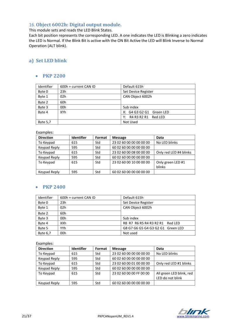
16. Object 6002h: Digital output module. This module sets and reads the LED Blink States. Each bit position represents the corresponding LED. A one indicates the LED is Blinking a zero indicates the LED is Normal. If the Blink Bit is active with the ON Bit Active the LED will Blink Inverse to Normal Operation (ALT blink).
a) Set LED blink
PKP 2200
Identifier 600h + current CAN ID Default 615h
Byte 0 23h Set Device Register
Byte 1 02h CAN Object 6002h
Byte 2 60h
Byte 3 00h Sub index
Byte 4 XYh X: G4 G3 G2 G1 Green LED
Y: R4 R3 R2 R1 Red LED
Byte 5,7 Not Used
Examples:
Direction Identifier Format Message Data
To Keypad 615 Std 23 02 60 00 00 00 00 00 No LED blinks
Keypad Reply 595 Std 60 02 60 00 00 00 00 00
To Keypad 615 Std 23 02 60 00 08 00 00 00 Only red LED #4 blinks
Keypad Reply 595 Std 60 02 60 00 00 00 00 00
To Keypad 615 Std 23 02 60 00 10 00 00 00 Only green LED #1 blinks
Keypad Reply 595 Std 60 02 60 00 00 00 00 00
PKP 2400
Identifier 600h + current CAN ID Default 615h
Byte 0 23h Set Device Register
Byte 1 02h CAN Object 6002h
Byte 2 60h
Byte 3 00h Sub index
Byte 4 XXh R8 R7 R6 R5 R4 R3 R2 R1 Red LED
Byte 5 YYh G8 G7 G6 G5 G4 G3 G2 G1 Green LED
Byte 6,7 00h Not used
Examples:
Direction Identifier Format Message Data
To Keypad 615 Std 23 02 60 00 00 00 00 00 No LED blinks
Keypad Reply 595 Std 60 02 60 00 00 00 00 00
To Keypad 615 Std 23 02 60 00 01 00 00 00 Only red LED #1 blinks
Keypad Reply 595 Std 60 02 60 00 00 00 00 00
To Keypad 615 Std 23 02 60 00 00 FF 00 00 All green LED blink, red LED do not blink
Keypad Reply 595 Std 60 02 60 00 00 00 00 00
www.blinkmarine.com PKPCANopenUM_REV1.4 22/37
PKP 2600
Identifier 600h + current CAN ID Default 615h
Byte 0 23h Set Device Register
Byte 1 02h CAN Object 6002h
Byte 2 60h
Byte 3 00h Sub index
Byte 4 XYh X: R8 R7 R6 R5 Red LED
Y: R4 R3 R2 R1 Red LED
Byte 5 ZKh Z: G4 G3 G2 G1 Green LED
K: R12 R11 R10 R9 Red LED
Byte 6 ABh A: G12 G11 G10 G9 Green LED
B: G8 G7 G6 G5 Green LED
Byte 7 00h Not used
Examples:
Direction Identifier Format Message Data
To Keypad 615 Std 23 02 60 00 00 00 00 00 No LED blinks
Keypad Reply 595 Std 60 02 60 00 00 00 00 00
To Keypad 615 Std 23 02 60 00 10 20 40 00 Only red LED #5, green LED #2 and #11 blink.
Keypad Reply 595 Std 60 02 60 00 00 00 00 00
To Keypad 615 Std 23 02 60 00 00 00 05 00 Only green LED #5 and #7 blink.
Keypad Reply 595 Std 60 02 60 00 00 00 00 00
b) Read LED blink
PKP 2200
Identifier 600h + current CAN ID Default 615h
Byte 0 40h Read Device Register
Byte 1 02h CAN Object 6002h
Byte 2 60h
Byte 3 00h Sub index
Byte 4,7 00h Not Used
Examples:
Direction Identifier Format Message Data
To Keypad 615 Std 40 02 60 00 00 00 00 00
Keypad Reply 595 Std 43 02 60 00 FF 00 00 00 All LED blink
To Keypad 615 Std 40 02 60 00 00 00 00 00
Keypad Reply 595 Std 43 02 60 00 81 00 00 00 Red LED #1and green LED #4 blink
To Keypad 615 Std 40 02 60 00 00 00 00 00
Keypad Reply 595 Std 43 02 60 00 08 00 00 00 Red LED #4 blink
23/37 PKPCANopenUM_REV1.4 www.blinkmarine.com
PKP 2400
Identifier 600h + current CAN ID Default 615h
Byte 0 40h Read Device Register
Byte 1 02h CAN Object 6002h
Byte 2 60h
Byte 3 00h Sub index
Byte 4,7 00h Not Used
Examples:
Direction Identifier Format Message Data
To Keypad 615 Std 40 02 60 00 00 00 00 00
Keypad Reply 595 Std 43 02 60 00 FF 00 00 00 All red LED blink
To Keypad 615 Std 40 02 60 00 00 00 00 00
Keypad Reply 595 Std 43 02 60 00 00 FF 00 00 All green LED blink
To Keypad 615 Std 40 02 60 00 00 00 00 00
Keypad Reply 595 Std 43 02 60 00 00 01 00 00 Green LED #1 blink
PKP 2600
Identifier 600h + current CAN ID Default 615h
Byte 0 40h Read Device Register
Byte 1 02h CAN Object 6002h
Byte 2 60h
Byte 3 00h Sub index
Byte 4,7 00h Not Used
Examples:
Direction Identifier Format Message Data
To Keypad 615 Std 40 02 60 00 00 00 00 00
Keypad Reply 595 Std 43 02 60 00 00 00 01 00 Green LED #5 blink
To Keypad 615 Std 40 02 60 00 00 00 00 00
Keypad Reply 595 Std 43 02 60 00 80 40 20 00 Green LED #3, #8 and #10 blink
To Keypad 615 Std 40 02 60 00 00 00 00 00
Keypad Reply 595 Std 43 02 60 00 08 00 00 00 Red LED #4 blink
www.blinkmarine.com PKPCANopenUM_REV1.4 24/37
17. Object 1017h: Producer heartbeat time The producer heartbeat time shall indicate the configured cycle time of the heartbeat.
Identifier 600h + current CAN ID Default 615h
Byte 0 40h Read Device Register
2B Set device register
Byte 1 17h CAN Object 1017h
Byte 2 10h
Byte 3 00h Sub index
Byte 4 YYh YYh: Heartbeat time in milliseconds
Byte 5 XXh XXh: Heartbeat time in milliseconds
Byte 5, 7 00h Not used
Heartbeat time: XXYYh minimum 000Ah maximum FFFFh milliseconds. Examples:
Direction Identifier Format Message Data
To Keypad 615 Std 40 17 10 00 00 00 00 00 Read heartbeat time
Keypad Reply 595 Std 4B 17 10 00 64 00 00 00 Heartbeat time = 100ms
To Keypad 615 Std 2B 17 10 00 00 00 00 00 Switch off the heartbeat
Keypad Reply 595 Std 60 17 10 00 00 00 00 00
To Keypad 615 Std 2B 17 10 00 32 00 00 00 Set heartbeat time = 50ms
Keypad Reply 595 Std 60 17 10 00 00 00 00 00
To Keypad 615 Std 2B 17 10 00 F4 01 00 00 Set heartbeat time = 500ms
Keypad Reply 595 Std 60 17 10 00 00 00 00 00
18. Object 1000h: Device Type
Identifier 600h + current CAN ID Default 615h
Byte 0 40h Read Device Register
Byte 1 00h CAN Object 1000h
Byte 2 10h
Byte 3, 7 00h Not used
Example:
Direction Identifier Format Data
To Keypad 615 Std 40 00 10 00 00 00 00 00
Keypad Reply 595 Std 43 00 10 00 91 01 03 00
Device profile number 30191h.
25/37 PKPCANopenUM_REV1.4 www.blinkmarine.com
19. Object 1008h: Manufacturer Device Name
Identifier 600h + current CAN ID Default 615h
Byte 0 40h Read Device Register
Byte 1 08h CAN Object 1008h
Byte 2 10h
Byte 3, 7 00h Non used
1° additional byte
Identifier 600h + current CAN ID Default 615h
Byte 0 60h Read Device Register Next Byte
Byte 1, 7 00h Not used
2° additional byte
Identifier 600h + current CAN ID Default 615h
Byte 0 70h Read Device Register Next Byte
Byte 1, 7 00h Not used
Example:
Direction Identifier Format Message Data
To Keypad 615 Std 40 08 10 00 00 00 00 00
Keypad Reply 595 Std 41 08 10 00 0B 00 00 00
To Keypad 615 Std 60 00 00 00 00 00 00 00
Keypad Reply 595 Std 00 44 4E 41 20 67 72 6F DNA Gro
To Keypad 615 Std 70 00 00 00 00 00 00 00
Keypad Reply 595 Std 19 75 70 00 00 00 00 00 up
Manufacturer Device Name: DNA Group The first byte of the last data message replied is 19h.
www.blinkmarine.com PKPCANopenUM_REV1.4 26/37
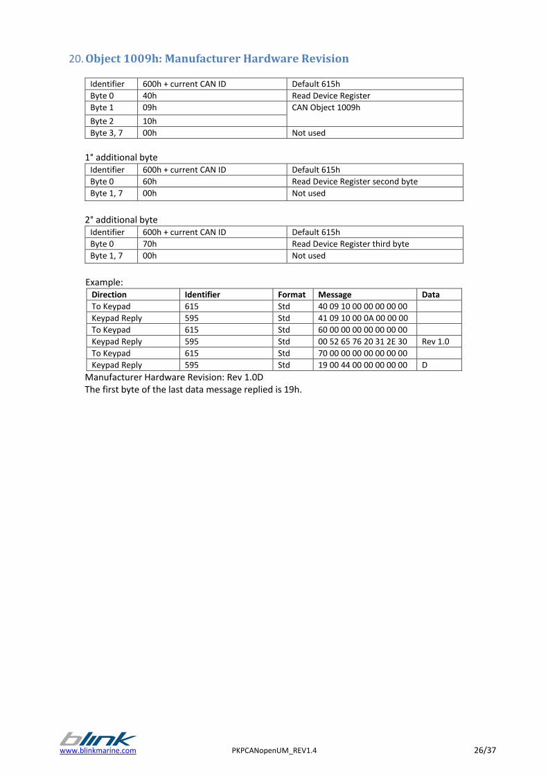
20. Object 1009h: Manufacturer Hardware Revision
Identifier 600h + current CAN ID Default 615h
Byte 0 40h Read Device Register
Byte 1 09h CAN Object 1009h
Byte 2 10h
Byte 3, 7 00h Not used
1° additional byte
Identifier 600h + current CAN ID Default 615h
Byte 0 60h Read Device Register second byte
Byte 1, 7 00h Not used
2° additional byte
Identifier 600h + current CAN ID Default 615h
Byte 0 70h Read Device Register third byte
Byte 1, 7 00h Not used
Example:
Direction Identifier Format Message Data
To Keypad 615 Std 40 09 10 00 00 00 00 00
Keypad Reply 595 Std 41 09 10 00 0A 00 00 00
To Keypad 615 Std 60 00 00 00 00 00 00 00
Keypad Reply 595 Std 00 52 65 76 20 31 2E 30 Rev 1.0
To Keypad 615 Std 70 00 00 00 00 00 00 00
Keypad Reply 595 Std 19 00 44 00 00 00 00 00 D
Manufacturer Hardware Revision: Rev 1.0D The first byte of the last data message replied is 19h.
27/37 PKPCANopenUM_REV1.4 www.blinkmarine.com
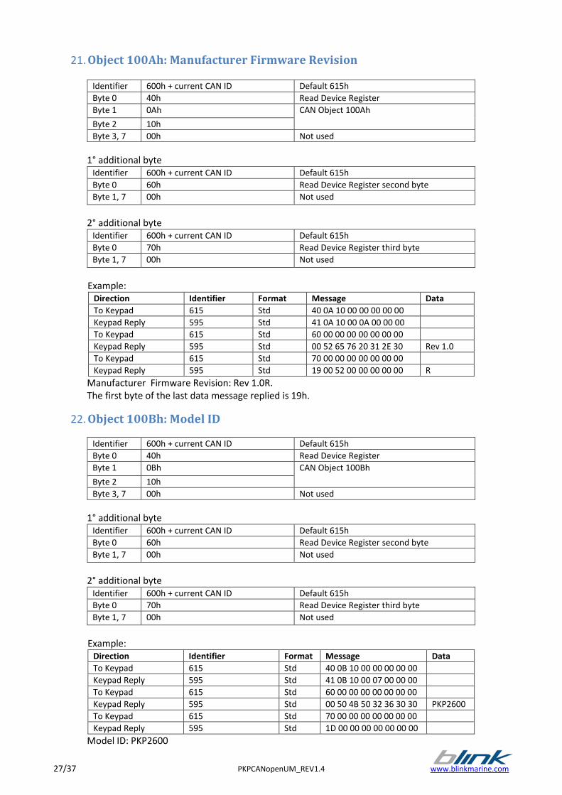
21. Object 100Ah: Manufacturer Firmware Revision
Identifier 600h + current CAN ID Default 615h
Byte 0 40h Read Device Register
Byte 1 0Ah CAN Object 100Ah
Byte 2 10h
Byte 3, 7 00h Not used
1° additional byte Identifier 600h + current CAN ID Default 615h
Byte 0 60h Read Device Register second byte
Byte 1, 7 00h Not used
2° additional byte Identifier 600h + current CAN ID Default 615h
Byte 0 70h Read Device Register third byte
Byte 1, 7 00h Not used
Example: Direction Identifier Format Message Data
To Keypad 615 Std 40 0A 10 00 00 00 00 00
Keypad Reply 595 Std 41 0A 10 00 0A 00 00 00
To Keypad 615 Std 60 00 00 00 00 00 00 00
Keypad Reply 595 Std 00 52 65 76 20 31 2E 30 Rev 1.0
To Keypad 615 Std 70 00 00 00 00 00 00 00
Keypad Reply 595 Std 19 00 52 00 00 00 00 00 R
Manufacturer Firmware Revision: Rev 1.0R. The first byte of the last data message replied is 19h.
22. Object 100Bh: Model ID
Identifier 600h + current CAN ID Default 615h
Byte 0 40h Read Device Register
Byte 1 0Bh CAN Object 100Bh
Byte 2 10h
Byte 3, 7 00h Not used
1° additional byte Identifier 600h + current CAN ID Default 615h
Byte 0 60h Read Device Register second byte
Byte 1, 7 00h Not used
2° additional byte Identifier 600h + current CAN ID Default 615h
Byte 0 70h Read Device Register third byte
Byte 1, 7 00h Not used
Example: Direction Identifier Format Message Data
To Keypad 615 Std 40 0B 10 00 00 00 00 00
Keypad Reply 595 Std 41 0B 10 00 07 00 00 00
To Keypad 615 Std 60 00 00 00 00 00 00 00
Keypad Reply 595 Std 00 50 4B 50 32 36 30 30 PKP2600
To Keypad 615 Std 70 00 00 00 00 00 00 00
Keypad Reply 595 Std 1D 00 00 00 00 00 00 00
Model ID: PKP2600
www.blinkmarine.com PKPCANopenUM_REV1.4 28/37
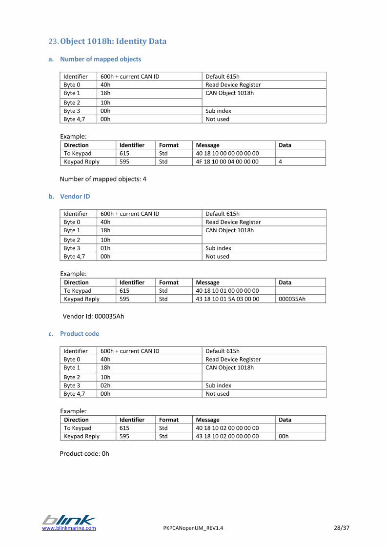
23. Object 1018h: Identity Data
a. Number of mapped objects
Identifier 600h + current CAN ID Default 615h
Byte 0 40h Read Device Register
Byte 1 18h CAN Object 1018h
Byte 2 10h
Byte 3 00h Sub index
Byte 4,7 00h Not used
Example:
Direction Identifier Format Message Data
To Keypad 615 Std 40 18 10 00 00 00 00 00
Keypad Reply 595 Std 4F 18 10 00 04 00 00 00 4
Number of mapped objects: 4
b. Vendor ID
Identifier 600h + current CAN ID Default 615h
Byte 0 40h Read Device Register
Byte 1 18h CAN Object 1018h
Byte 2 10h
Byte 3 01h Sub index
Byte 4,7 00h Not used
Example:
Direction Identifier Format Message Data
To Keypad 615 Std 40 18 10 01 00 00 00 00
Keypad Reply 595 Std 43 18 10 01 5A 03 00 00 000035Ah
Vendor Id: 000035Ah
c. Product code
Identifier 600h + current CAN ID Default 615h
Byte 0 40h Read Device Register
Byte 1 18h CAN Object 1018h
Byte 2 10h
Byte 3 02h Sub index
Byte 4,7 00h Not used
Example:
Direction Identifier Format Message Data
To Keypad 615 Std 40 18 10 02 00 00 00 00
Keypad Reply 595 Std 43 18 10 02 00 00 00 00 00h
Product code: 0h
29/37 PKPCANopenUM_REV1.4 www.blinkmarine.com
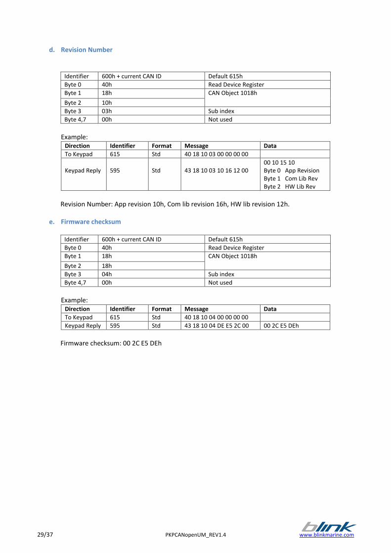
d. Revision Number
Identifier 600h + current CAN ID Default 615h
Byte 0 40h Read Device Register
Byte 1 18h CAN Object 1018h
Byte 2 10h
Byte 3 03h Sub index
Byte 4,7 00h Not used
Example:
Direction Identifier Format Message Data
To Keypad 615 Std 40 18 10 03 00 00 00 00
Keypad Reply
595
Std
43 18 10 03 10 16 12 00
00 10 15 10 Byte 0 App Revision Byte 1 Com Lib Rev Byte 2 HW Lib Rev
Revision Number: App revision 10h, Com lib revision 16h, HW lib revision 12h.
e. Firmware checksum
Identifier 600h + current CAN ID Default 615h
Byte 0 40h Read Device Register
Byte 1 18h CAN Object 1018h
Byte 2 18h
Byte 3 04h Sub index
Byte 4,7 00h Not used
Example:
Direction Identifier Format Message Data
To Keypad 615 Std 40 18 10 04 00 00 00 00
Keypad Reply 595 Std 43 18 10 04 DE E5 2C 00 00 2C E5 DEh
Firmware checksum: 00 2C E5 DEh
www.blinkmarine.com PKPCANopenUM_REV1.4 30/37
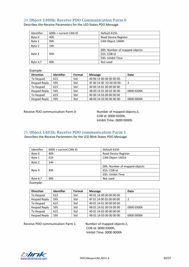
24. Object 1400h: Receive PDO Communication Parm 0 Describes the Receive Parameters for the LED States PDO Message.
Identifier 600h + current CAN ID Default 615h
Byte 0 40h Read Device Register
Byte 1 00h CAN Object 1400h
Byte 2 14h
Byte 3
XXh
00h: Number of mapped objects
01h: COB Id
03h: Inhibit Time
Byte 4,7 00h Not used
Example:
Direction Identifier Format Message Data
To Keypad 615 Std 40 00 14 00 00 00 00 00
Keypad Reply 595 Std 4F 00 14 00 02 00 00 00 2
To Keypad 615 Std 40 00 14 01 00 00 00 00
Keypad Reply 595 Std 4B 00 14 01 00 02 00 00 0000 0200h
To Keypad 615 Std 40 00 14 03 00 00 00 00
Keypad Reply 595 Std 4B 00 14 03 00 00 00 00 0000 0000h
Receive PDO communication Parm 0: Number of mapped objects:2,
COB id: 0000 0200h, Inhibit Time: 0000 0000h
25. Object 1401h: Receive PDO communication Parm 1 Describes the Receive Parameters for the LED Blink States PDO Message.
Identifier 600h + current CAN ID Default 615h
Byte 0 40h Read Device Register
Byte 1 01h CAN Object 1401h
Byte 2 14h
Byte 3
XXh
00h: Number of mapped objects
01h: COB Id
03h: Inhibit Time
Byte 4,7 00h Not used
Example:
Direction Identifier Format Message Data
To Keypad 615 Std 40 01 14 00 00 00 00 00
Keypad Reply 595 Std 4F 01 14 00 02 00 00 00 2
To Keypad 615 Std 40 01 14 01 00 00 00 00
Keypad Reply 595 Std 4B 01 14 01 00 03 00 00 0000 0300h
To Keypad 615 Std 40 01 14 03 00 00 00 00
Keypad Reply 595 Std 4B 01 14 03 00 00 00 00 0000 0000h
Receive PDO communication Parm 1: Number of mapped objects:2,
COB id: 0000 0300h, Inhibit Time: 0000 0000h
31/37 PKPCANopenUM_REV1.4 www.blinkmarine.com
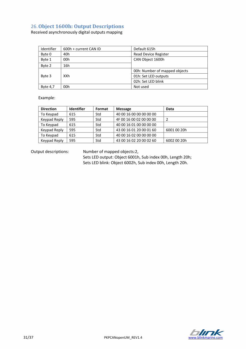
26. Object 1600h: Output Descriptions Received asynchronously digital outputs mapping
Identifier 600h + current CAN ID Default 615h
Byte 0 40h Read Device Register
Byte 1 00h CAN Object 1600h
Byte 2 16h
Byte 3
XXh
00h: Number of mapped objects
01h: Set LED outputs
02h: Set LED blink
Byte 4,7 00h Not used
Example:
Direction Identifier Format Message Data
To Keypad 615 Std 40 00 16 00 00 00 00 00
Keypad Reply 595 Std 4F 00 16 00 02 00 00 00 2
To Keypad 615 Std 40 00 16 01 00 00 00 00
Keypad Reply 595 Std 43 00 16 01 20 00 01 60 6001 00 20h
To Keypad 615 Std 40 00 16 02 00 00 00 00
Keypad Reply 595 Std 43 00 16 02 20 00 02 60 6002 00 20h
Output descriptions: Number of mapped objects:2,
Sets LED output: Object 6001h, Sub index 00h, Length 20h; Sets LED blink: Object 6002h, Sub index 00h, Length 20h.
www.blinkmarine.com PKPCANopenUM_REV1.4 32/37
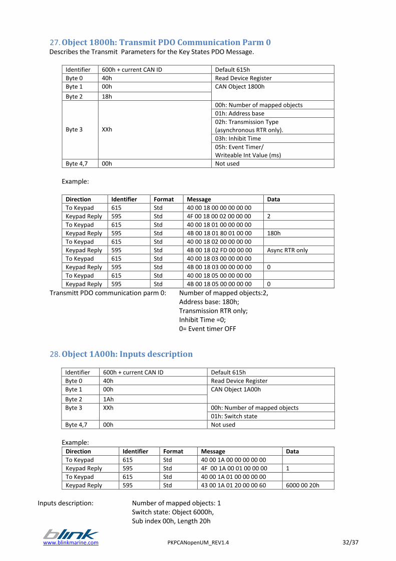
27. Object 1800h: Transmit PDO Communication Parm 0 Describes the Transmit Parameters for the Key States PDO Message.
Identifier 600h + current CAN ID Default 615h
Byte 0 40h Read Device Register
Byte 1 00h CAN Object 1800h
Byte 2 18h
Byte 3
XXh
00h: Number of mapped objects
01h: Address base
02h: Transmission Type (asynchronous RTR only).
03h: Inhibit Time
05h: Event Timer/ Writeable Int Value (ms)
Byte 4,7 00h Not used
Example:
Direction Identifier Format Message Data
To Keypad 615 Std 40 00 18 00 00 00 00 00
Keypad Reply 595 Std 4F 00 18 00 02 00 00 00 2
To Keypad 615 Std 40 00 18 01 00 00 00 00
Keypad Reply 595 Std 4B 00 18 01 80 01 00 00 180h
To Keypad 615 Std 40 00 18 02 00 00 00 00
Keypad Reply 595 Std 4B 00 18 02 FD 00 00 00 Async RTR only
To Keypad 615 Std 40 00 18 03 00 00 00 00
Keypad Reply 595 Std 4B 00 18 03 00 00 00 00 0
To Keypad 615 Std 40 00 18 05 00 00 00 00
Keypad Reply 595 Std 4B 00 18 05 00 00 00 00 0
Transmitt PDO communication parm 0: Number of mapped objects:2, Address base: 180h; Transmission RTR only;
Inhibit Time =0; 0= Event timer OFF
28. Object 1A00h: Inputs description
Identifier 600h + current CAN ID Default 615h
Byte 0 40h Read Device Register
Byte 1 00h CAN Object 1A00h
Byte 2 1Ah
Byte 3 XXh 00h: Number of mapped objects
01h: Switch state
Byte 4,7 00h Not used
Example:
Direction Identifier Format Message Data
To Keypad 615 Std 40 00 1A 00 00 00 00 00
Keypad Reply 595 Std 4F 00 1A 00 01 00 00 00 1
To Keypad 615 Std 40 00 1A 01 00 00 00 00
Keypad Reply 595 Std 43 00 1A 01 20 00 00 60 6000 00 20h
Inputs description: Number of mapped objects: 1 Switch state: Object 6000h,
Sub index 00h, Length 20h
33/37 PKPCANopenUM_REV1.4 www.blinkmarine.com
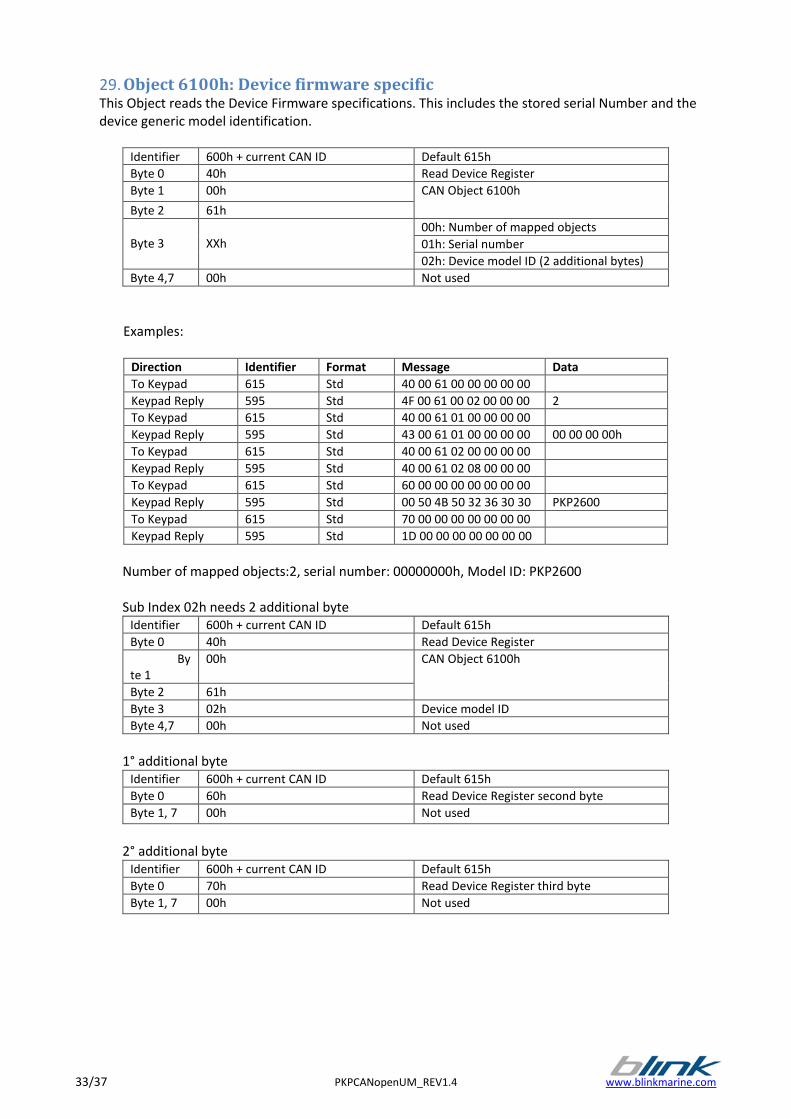
29. Object 6100h: Device firmware specific This Object reads the Device Firmware specifications. This includes the stored serial Number and the device generic model identification.
Identifier 600h + current CAN ID Default 615h
Byte 0 40h Read Device Register
Byte 1 00h CAN Object 6100h
Byte 2 61h
Byte 3
XXh
00h: Number of mapped objects
01h: Serial number
02h: Device model ID (2 additional bytes)
Byte 4,7 00h Not used
Examples:
Direction Identifier Format Message Data
To Keypad 615 Std 40 00 61 00 00 00 00 00
Keypad Reply 595 Std 4F 00 61 00 02 00 00 00 2
To Keypad 615 Std 40 00 61 01 00 00 00 00
Keypad Reply 595 Std 43 00 61 01 00 00 00 00 00 00 00 00h
To Keypad 615 Std 40 00 61 02 00 00 00 00
Keypad Reply 595 Std 40 00 61 02 08 00 00 00
To Keypad 615 Std 60 00 00 00 00 00 00 00
Keypad Reply 595 Std 00 50 4B 50 32 36 30 30 PKP2600
To Keypad 615 Std 70 00 00 00 00 00 00 00
Keypad Reply 595 Std 1D 00 00 00 00 00 00 00
Number of mapped objects:2, serial number: 00000000h, Model ID: PKP2600
Sub Index 02h needs 2 additional byte
Identifier 600h + current CAN ID Default 615h
Byte 0 40h Read Device Register
Byte 1
00h CAN Object 6100h
Byte 2 61h
Byte 3 02h Device model ID
Byte 4,7 00h Not used
1° additional byte
Identifier 600h + current CAN ID Default 615h
Byte 0 60h Read Device Register second byte
Byte 1, 7 00h Not used
2° additional byte
Identifier 600h + current CAN ID Default 615h
Byte 0 70h Read Device Register third byte
Byte 1, 7 00h Not used
www.blinkmarine.com PKPCANopenUM_REV1.4 34/37
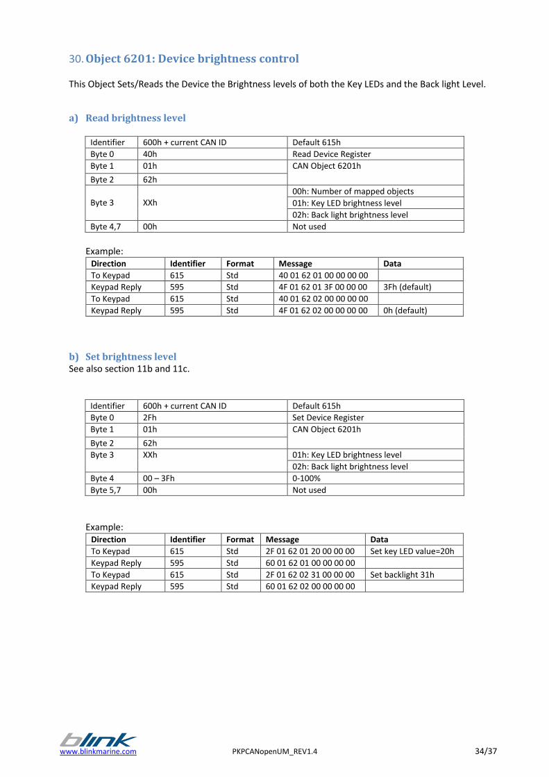
30. Object 6201: Device brightness control
This Object Sets/Reads the Device the Brightness levels of both the Key LEDs and the Back light Level.
a) Read brightness level
Identifier 600h + current CAN ID Default 615h
Byte 0 40h Read Device Register
Byte 1 01h CAN Object 6201h
Byte 2 62h
Byte 3
XXh
00h: Number of mapped objects
01h: Key LED brightness level
02h: Back light brightness level
Byte 4,7 00h Not used
Example:
Direction Identifier Format Message Data
To Keypad 615 Std 40 01 62 01 00 00 00 00
Keypad Reply 595 Std 4F 01 62 01 3F 00 00 00 3Fh (default)
To Keypad 615 Std 40 01 62 02 00 00 00 00
Keypad Reply 595 Std 4F 01 62 02 00 00 00 00 0h (default)
b) Set brightness level See also section 11b and 11c.
Identifier 600h + current CAN ID Default 615h
Byte 0 2Fh Set Device Register
Byte 1 01h CAN Object 6201h
Byte 2 62h
Byte 3 XXh 01h: Key LED brightness level
02h: Back light brightness level
Byte 4 00 – 3Fh 0-100%
Byte 5,7 00h Not used
Example: Direction Identifier Format Message Data
To Keypad 615 Std 2F 01 62 01 20 00 00 00 Set key LED value=20h
Keypad Reply 595 Std 60 01 62 01 00 00 00 00
To Keypad 615 Std 2F 01 62 02 31 00 00 00 Set backlight 31h
Keypad Reply 595 Std 60 01 62 02 00 00 00 00
35/37 PKPCANopenUM_REV1.4 www.blinkmarine.com
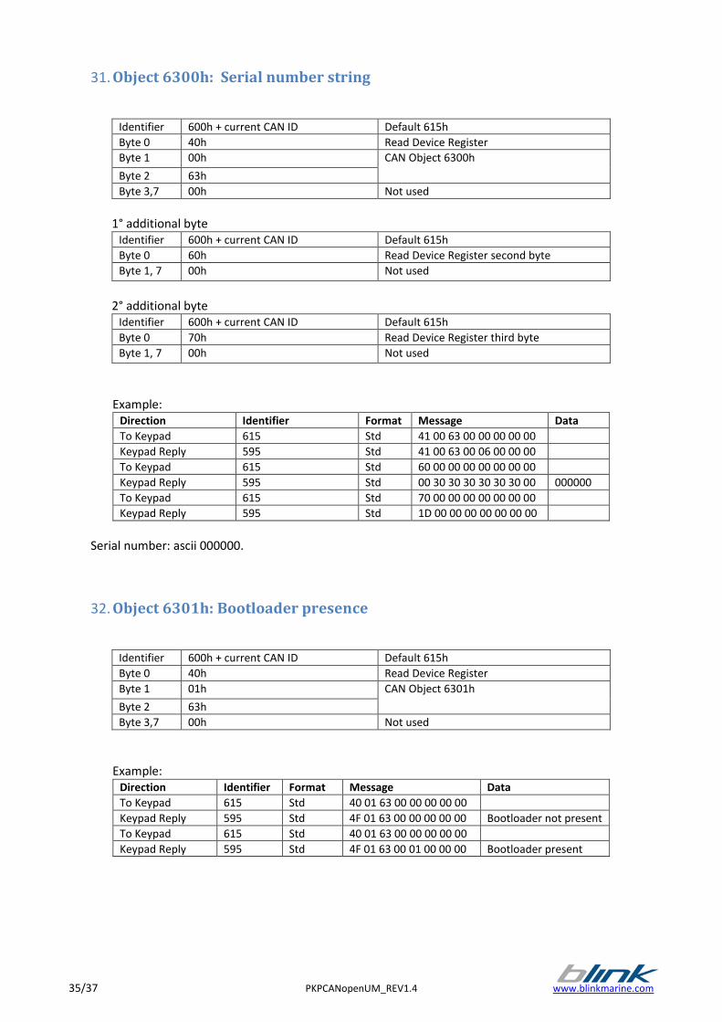
31. Object 6300h: Serial number string
Identifier 600h + current CAN ID Default 615h
Byte 0 40h Read Device Register
Byte 1 00h CAN Object 6300h
Byte 2 63h
Byte 3,7 00h Not used
1° additional byte
Identifier 600h + current CAN ID Default 615h
Byte 0 60h Read Device Register second byte
Byte 1, 7 00h Not used
2° additional byte
Identifier 600h + current CAN ID Default 615h
Byte 0 70h Read Device Register third byte
Byte 1, 7 00h Not used
Example:
Direction Identifier Format Message Data
To Keypad 615 Std 41 00 63 00 00 00 00 00
Keypad Reply 595 Std 41 00 63 00 06 00 00 00
To Keypad 615 Std 60 00 00 00 00 00 00 00
Keypad Reply 595 Std 00 30 30 30 30 30 30 00 000000
To Keypad 615 Std 70 00 00 00 00 00 00 00
Keypad Reply 595 Std 1D 00 00 00 00 00 00 00
Serial number: ascii 000000.
32. Object 6301h: Bootloader presence
Identifier 600h + current CAN ID Default 615h
Byte 0 40h Read Device Register
Byte 1 01h CAN Object 6301h
Byte 2 63h
Byte 3,7 00h Not used
Example: Direction Identifier Format Message Data
To Keypad 615 Std 40 01 63 00 00 00 00 00
Keypad Reply 595 Std 4F 01 63 00 00 00 00 00 Bootloader not present
To Keypad 615 Std 40 01 63 00 00 00 00 00
Keypad Reply 595 Std 4F 01 63 00 01 00 00 00 Bootloader present
www.blinkmarine.com PKPCANopenUM_REV1.4 36/37
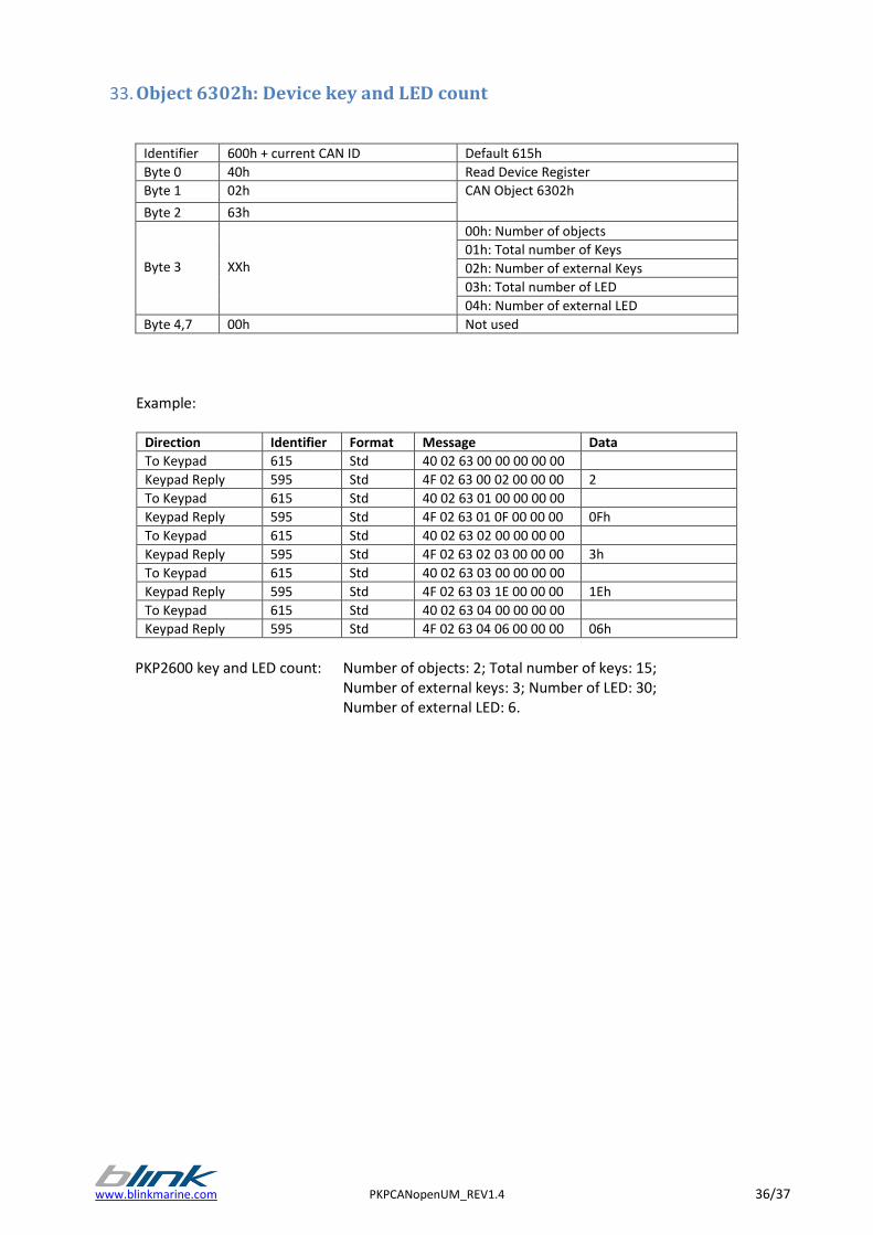
33. Object 6302h: Device key and LED count
Identifier 600h + current CAN ID Default 615h
Byte 0 40h Read Device Register
Byte 1 02h CAN Object 6302h
Byte 2 63h
Byte 3
XXh
00h: Number of objects
01h: Total number of Keys
02h: Number of external Keys
03h: Total number of LED
04h: Number of external LED
Byte 4,7 00h Not used
Example:
Direction Identifier Format Message Data
To Keypad 615 Std 40 02 63 00 00 00 00 00
Keypad Reply 595 Std 4F 02 63 00 02 00 00 00 2
To Keypad 615 Std 40 02 63 01 00 00 00 00
Keypad Reply 595 Std 4F 02 63 01 0F 00 00 00 0Fh
To Keypad 615 Std 40 02 63 02 00 00 00 00
Keypad Reply 595 Std 4F 02 63 02 03 00 00 00 3h
To Keypad 615 Std 40 02 63 03 00 00 00 00
Keypad Reply 595 Std 4F 02 63 03 1E 00 00 00 1Eh
To Keypad 615 Std 40 02 63 04 00 00 00 00
Keypad Reply 595 Std 4F 02 63 04 06 00 00 00 06h
PKP2600 key and LED count: Number of objects: 2; Total number of keys: 15; Number of external keys: 3; Number of LED: 30; Number of external LED: 6.

37/37 PKPCANopenUM_REV1.4 www.blinkmarine.com
Check for updates on www.blinkmarine.com/download