powering single-corded equipment in a dual path · pdf file · 2011-07-08power bus...
TRANSCRIPT

Powering Single-corded Equipment in a Dual Path Environment
Revision 1
by Victor Avelar
Introduction 2
Transfer switch functions 2
Types of transfer switches 3
IT equipment power supplies 7
Selecting the appropriatetransfer switches
7
Conclusion 11
Resources 12
Appendix 13
Click on a section to jump to it Contents
White Paper 62
The use of dual power path architecture in combination with IT equipment with dual power supplies and power cords is an industry best-practice. In facilities using this approach there are inevitably some IT devices which have only a single power cord. There are a number of options for integrating single-corded devices into a high availability dual path data center. This paper explains the differences between the various options and provides a guide to selecting the appropriate approach.
Executive summary>
white papers are now part of the Schneider Electric white paper libraryproduced by Schneider Electric’s Data Center Science Center [email protected]

Powering Single-Corded Equipment in a Dual Path Environment
Schneider Electric – Data Center Science Center White Paper 62 Rev 1 2
Most high availability data centers use a power system providing dual power paths all the way to the critical loads, and most enterprise class IT equipment offers redundant power supplies and power cords to maintain the dual power paths all the way to the IT equipment internal power bus. In this way the equipment can continue to operate with a failure at any point in either power path. However, equipment with a single power supply (single-corded) introduc-es a weakness into an otherwise highly available data center. Transfer switches are often used to enhance single-corded equipment availability by providing the benefits of redundant utility paths. If not understood, this practice can lead to downtime that would have otherwise been avoided. There are three fundamental approaches to powering single-corded equipment in a dual path environment. They are: • Power equipment from one feed – Figure 1a
• Use a transfer switch at the point of use to select a preferred source, and when that source fails switch to the second power path – Figure 1b
• Use a large centralized transfer switch fed from the two sources, to generate a new power bus to supply a large group of single corded loads – Figure 1c
A transfer switch is a common component in data centers and is used to perform the follow-ing functions:
1. Switching UPS and other loads from utility to generator during a utility power failure
2. Switching from a failed UPS module to utility or another UPS (depending on designs)
3. Switching critical IT loads from one UPS output bus to another in a dual path power system
This paper will focus solely on the third function. If all IT loads were capable of accepting dual input power feeds (i.e. dual-corded), then there would be no need for this application. In fact, most high end internetworking equipment, storage devices, and servers do have fully
Introduction
PDU
Subpanel2
Subpanel1
Transformer2
Transformer1
PDU
Backup power path
Primary power path
UPS 1
UPS 2
Server
X
PDU with STS
StaticTransferSwitch
Step DownTransformer Subpanel Server
Backup power path
Primary power path
UPS 1
UPS 2
PDU
Subpanel2
Subpanel1
Transformer2
Transformer1
PDU
Backup power path
Primary power path
UPS 1
UPS 2
ServerRackmountTransfer Switch
Figure 1a (top left) One feed 1b (top right) Point of use switch 1c (bottom) Centralized switching
Transfer switch functions

Powering Single-Corded Equipment in a Dual Path Environment
Schneider Electric – Data Center Science Center White Paper 62 Rev 1 3
redundant input power supplies and dual power cords. However, single-corded equipment still makes up about 10-20% of all IT equipment in mission-critical facilities. When single-corded equipment is plugged into a single utility path of a dual-utility path environment, the overall business process availability may be jeopardized. According to White Paper 48, Comparing Availability of Various Rack Power Redundancy Configurations, a 100% dual-corded data center with redundant and independent utility paths can provide 10,000 times less down time than a single path design. Transfer switches help to close this wide gap, by bringing redundant utility paths closer to the load. There are two main types or transfer switches used as best source selectors: static and electro-mechanical. Both are based on the principle of switching between a primary power source and an alternate power source. Although they provide the same outcome, they go about it in different ways. Each type of switch has unique characteristics that benefit different types of applications. A brief overview of how each type works is provided below and a more detailed description is provided in Appendix A. Static transfer switches (STS) Applications Static transfer switches available today are as small as 5 kVA and can be as large as 35 MVA. STS units are used in a wide array of applications including electric utilities, automo-bile manufacturing plants, semiconductor fabs, oil refineries, and data centers. Most of these switches fall in the range of 100 - 300 kVA and are typically the footprint of two IT racks side by side. In applications like refineries where both the power grid and electrical architecture are less reliable than those of mission critical data centers, there is little debate as to the benefits of static switches. However, the power grid and electrical architecture of mission critical data centers are much more robust. In these cases, the decrease in reliability associated with adding STS outweighs the benefit they offer. An example of a 200 kVA STS is shown in Figure 2. Static switches of this capacity are best suited for large 3-phase single-corded loads such as CNC machines and other critical manufacturing equipment. Although large 3-phase IT equipment such as storage devices is available today, it is generally dual-corded with redundant power supplies. In cases of dual corded devices, power reliability and availability are optimized by bringing the dual utility sources directly to the load. The static switches that fall in the 5-10 kVA range are generally designed to mount in a standard 19 inch (483 mm) IT rack enclosure as shown in Figure 3. Static switches of this type are generally used in IT environments such as wiring closets and data rooms. Utilizing smaller switches prevents an STS failure from affecting a large portion of the data center and instead mitigates the downtime to the single-corded equipment in one rack. Unlike larger capacity STS, rack mount switches allow for scalability and agility. The lead time for smaller switches allows IT managers to buy a switch only when the need arises. Furthermore, these switches can be easily installed and moved around as a function of IT refreshes.
Comparing Availability or Various Rack Power Redundancy Configurations
Related resource White Paper 48
Types of transfer switches

Powering Single-Corded Equipment in a Dual Path Environment
Schneider Electric – Data Center Science Center White Paper 62 Rev 1 4
Operation As the name implies, static switches are free of moving parts. This is made possible as a result of semiconductor technology. The “switch” in a single-phase STS is essentially comprised of two pairs of semiconductor switches called silicon controlled rectifiers (SCR), also called thyristors, which are controlled by a sensing circuit. When the circuit senses that the primary path is out of tolerance, it disconnects the primary path switch and connects the alternate path switch. Switching duration is usually about 4 milliseconds but can be slightly longer depending on the state of both sources. Failure modes In general, the more complex a system is, the more failure modes are possible. Compared to electromechanical transfer switches, static switches are much more complex given the speed at which decisions must be made when switching between sources. (For instance, the controller must monitor several variables for both sides including phase angles, states of the SCR, and states of the circuit breakers, voltages and currents). • Static switch control failure
The controls are the single most critical component of static transfer switches due to their complexity. If the controls were to stop sending signals to the SCRs, the default state of the SCRs are to remain open i.e. will not conduct electricity thereby dropping the load. This is the reason why almost all static switches incorporate redundant controllers and
Figure 3 Rack mount STS
Figure 2 200 kVa STS
Source: www.cyberex.com
Source: http://www.powerparagon.com
Powering Single-Corded Equipment in a Dual Path Environment
Schneider Electric – Data Center Science Center White Paper 62 Rev 1 5
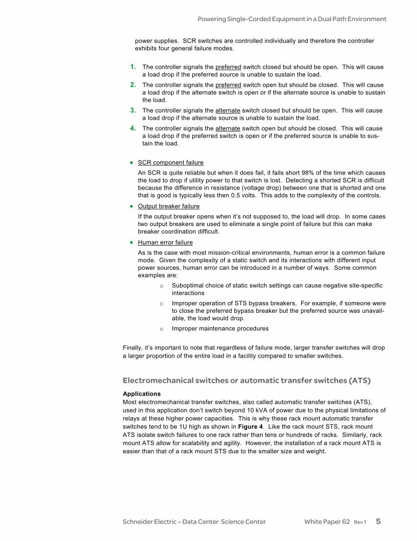
power supplies. SCR switches are controlled individually and therefore the controller exhibits four general failure modes.
1. The controller signals the preferred switch closed but should be open. This will cause
a load drop if the preferred source is unable to sustain the load.
2. The controller signals the preferred switch open but should be closed. This will cause a load drop if the alternate switch is open or if the alternate source is unable to sustain the load.
3. The controller signals the alternate switch closed but should be open. This will cause a load drop if the alternate source is unable to sustain the load.
4. The controller signals the alternate switch open but should be closed. This will cause a load drop if the preferred switch is open or if the preferred source is unable to sus-tain the load.
• SCR component failure
An SCR is quite reliable but when it does fail, it fails short 98% of the time which causes the load to drop if utility power to that switch is lost. Detecting a shorted SCR is difficult because the difference in resistance (voltage drop) between one that is shorted and one that is good is typically less then 0.5 volts. This adds to the complexity of the controls.
• Output breaker failure
If the output breaker opens when it’s not supposed to, the load will drop. In some cases two output breakers are used to eliminate a single point of failure but this can make breaker coordination difficult.
• Human error failure
As is the case with most mission-critical environments, human error is a common failure mode. Given the complexity of a static switch and its interactions with different input power sources, human error can be introduced in a number of ways. Some common examples are:
o Suboptimal choice of static switch settings can cause negative site-specific interactions
o Improper operation of STS bypass breakers. For example, if someone were to close the preferred bypass breaker but the preferred source was unavail-able, the load would drop.
o Improper maintenance procedures
Finally, it’s important to note that regardless of failure mode, larger transfer switches will drop a larger proportion of the entire load in a facility compared to smaller switches. Electromechanical switches or automatic transfer switches (ATS) Applications Most electromechanical transfer switches, also called automatic transfer switches (ATS), used in this application don’t switch beyond 10 kVA of power due to the physical limitations of relays at these higher power capacities. This is why these rack mount automatic transfer switches tend to be 1U high as shown in Figure 4. Like the rack mount STS, rack mount ATS isolate switch failures to one rack rather than tens or hundreds of racks. Similarly, rack mount ATS allow for scalability and agility. However, the installation of a rack mount ATS is easier than that of a rack mount STS due to the smaller size and weight.

Powering Single-Corded Equipment in a Dual Path Environment
Schneider Electric – Data Center Science Center White Paper 62 Rev 1 6
Operation Electromechanical switches depend on a combination of electrical and mechanical properties. Like the STS, these switches have a controller that monitors both input sources. The mechanism for transferring the load in this case is a relay. A relay is a mechanical switch that is held to one side by a magnetic force. When the controller senses that the primary source is out of tolerance, it de-energizes the relay and a spring forces the switch to the secondary source. The total transfer time for this type of transfer switch ranges from 8 to 16 milliseconds. Failure modes Electromechanical switches are much smaller and less complex then static transfer switches. This is mainly due to the fact that electromechanical switches are easier to control and don’t require synchronization between utility sources. Due to the physical movement of a relay, failure modes for electromechanical switches tend to be hardware based. • Relay weld failure
One possible failure mode is that the relay welds to the contact. This happens in cases of a high voltage transfer which causes a high temperature arc thereby welding the metal surfaces. In a 3-phase relay this may happen to one or more of the relay switch-es.
• Controller failure
Although it is less likely to happen at lower power capacities, it is possible that the con-troller could make the wrong switching decision. For instance, if the power on the pri-mary side is out of tolerance, the controller may switch to the secondary side which has not power at all.
• Controller power supply failure
The controller power supply can also cause misoperation of the controller. If the power supply voltage becomes unstable the controller may act unpredictably or may not act all.
• Circuit breaker failure
One important failure mode to be aware of is faulty circuit breakers protecting the output of the transfer switch. These breakers are oftentimes unreliable commodity parts and are a single point of failure.
Figure 4 Rack mount ATS
Powering Single-Corded Equipment in a Dual Path Environment
Schneider Electric – Data Center Science Center White Paper 62 Rev 1 7
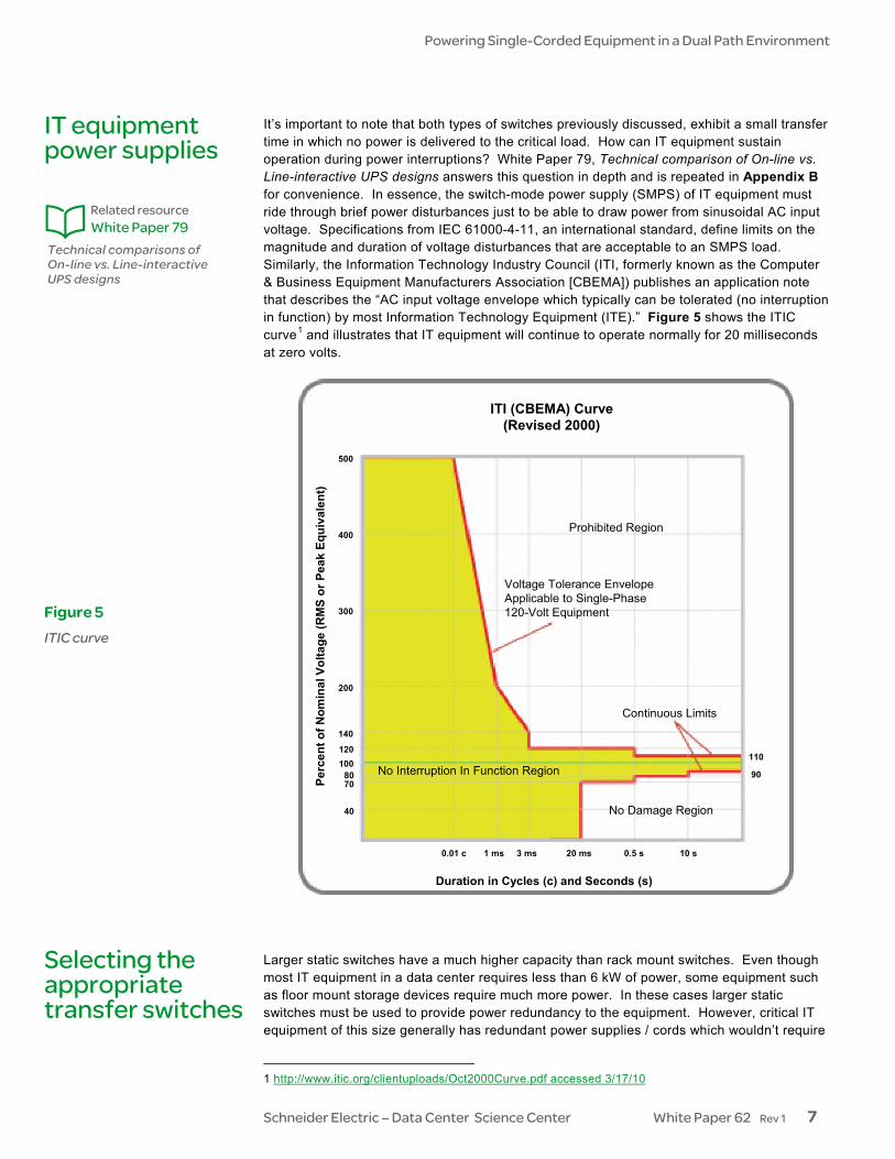
It’s important to note that both types of switches previously discussed, exhibit a small transfer time in which no power is delivered to the critical load. How can IT equipment sustain operation during power interruptions? White Paper 79, Technical comparison of On-line vs. Line-interactive UPS designs answers this question in depth and is repeated in Appendix B for convenience. In essence, the switch-mode power supply (SMPS) of IT equipment must ride through brief power disturbances just to be able to draw power from sinusoidal AC input voltage. Specifications from IEC 61000-4-11, an international standard, define limits on the magnitude and duration of voltage disturbances that are acceptable to an SMPS load. Similarly, the Information Technology Industry Council (ITI, formerly known as the Computer & Business Equipment Manufacturers Association [CBEMA]) publishes an application note that describes the “AC input voltage envelope which typically can be tolerated (no interruption in function) by most Information Technology Equipment (ITE).” Figure 5 shows the ITIC curve1 and illustrates that IT equipment will continue to operate normally for 20 milliseconds at zero volts.
10 s0.5 s20 ms3 ms1 ms0.01 c
40
7080
100120
140
200
300
400
500
Perc
ent o
f Nom
inal
Vol
tage
(RM
S or
Pea
k Eq
uiva
lent
)
Voltage Tolerance EnvelopeApplicable to Single-Phase120-Volt Equipment
No Interruption In Function Region
Prohibited Region
No Damage Region
Duration in Cycles (c) and Seconds (s)
ITI (CBEMA) Curve(Revised 2000)
Continuous Limits
110
90
Larger static switches have a much higher capacity than rack mount switches. Even though most IT equipment in a data center requires less than 6 kW of power, some equipment such as floor mount storage devices require much more power. In these cases larger static switches must be used to provide power redundancy to the equipment. However, critical IT equipment of this size generally has redundant power supplies / cords which wouldn’t require
1 http://www.itic.org/clientuploads/Oct2000Curve.pdf accessed 3/17/10
IT equipment power supplies
Technical comparisons of On-line vs. Line-interactive UPS designs
Related resource White Paper 79
Figure 5 ITIC curve
Selecting the appropriate transfer switches

Powering Single-Corded Equipment in a Dual Path Environment
Schneider Electric – Data Center Science Center White Paper 62 Rev 1 8
a static switch. Table 1 lists the power capacities for each type of switch and serves as a selection guide for the appropriate transfer switch. An additional choice of not using a transfer switch is also included. The subsections below describe each selection factor in TCO Total cost of ownership includes capital costs of purchasing and installing the transfer switch (es), and operational costs associated with using the switch (es). This topic is discussed further in White Paper 37, Avoiding Costs from Oversizing Data Center and Network Room Infrastructure. Capital costs Higher capacity static switches that are oversized, not only cost more per utilized kVA, but also result in lost opportunity costs. Larger static switches (greater then 10 kVA) are generally hardwired into the electrical infrastructure of the building. Smaller ATS and static switches are simply plugged into a receptacle thereby avoiding the expense of hiring electricians. Operational costs Operational costs include electrical utility, maintenance and tax implications. Static switches are less efficient than electromechanical switches due to the greater number of components. Efficiency becomes a greater concern when high capacity static switches are lightly loaded. Maintenance costs vary depending on the vendor’s recommendations; however, in general, maintenance costs for static switches are higher than ATS due to the higher complexity and component count. Tax implications aren’t generally considered when selecting transfer switches but can result in significant savings depending on data center size. White Paper 115, Accounting and Tax Benefits of Modular, Portable Data Center Infrastructure describes how modular portable electrical devices can be classified as business equipment resulting in tax savings (bigger tax shield). Transfer switches that are simply plugged in and are easily relocated can benefit from this rule. Manageability Manageability of the electrical infrastructure is critical to the integrity of the IT and telecom network. Oftentimes, critical failure modes only identify themselves when the switch must transfer to the alternate source. This is increasingly important in static switches since they have many more failure modes than electromechanical switches. Remotely managing transfer switches allows IT managers and facility managers to monitor status, log events, configure settings, perform firmware upgrades and receive alerts through email and SNMP. Switches should allow standards-based management via HTTP (Web), SNMP, and Telnet. Transfer time The transfer switch must be able to switch between sources in 20 milliseconds or less when supporting IT and telecom equipment. Ease of installation Given the high frequency of IT refreshes (1 ½ to 2 years), transfer switches should allow for quick reconfiguration. For example in cases when single-corded equipment is relocated, the transfer switch should be easily reconfigured.
Avoiding Costs from Oversizing Data Center and Network Room Infrastructure
Related resource White Paper 37
Accounting and Tax Benefits of Modular, Portable Data Center Infrastructure
Related resource White Paper 115
Powering Single-Corded Equipment in a Dual Path Environment
Schneider Electric – Data Center Science Center White Paper 62 Rev 1 9
Reliability In general, the more complex a system is, the greater the probability of something going wrong not only with its components and controls, but also with human intervention. Static switches are inherently more complex than electromechanical switches and hence require a higher level of understanding when operating and repairing them. Electromechanical switches are limited by the number of times the relay must switch. Relays used for this application are typically rated for 100,000 operations. On average, transfer switches in a data center environment experience four transfers per year. Therefore, relays provide a long life relative to the life of data centers. Quality of repair When systems fail, the goal of any IT or facility manager should be to replace the entire module with a factory repaired / refurbished one. Rack mountable static and electromechani-cal switches can be completely replaced, unlike larger STS which are repaired on-site with little to no standardized environment. However, most static switches incorporate bypass breakers to allow for maintenance and repair while the load is supported. Depending on the configuration, it is also possible to replace smaller electromechanical switches without bringing down the critical load. Source synchronization When switching between two utility sources, there’s a possibility that the sources are out of synchronization which may cause damage to equipment downstream of the switch or cause circuit breakers to trip. The likelihood of this happening increases with switching speed and transfer switch size. Therefore large static switches are much more prone to this problem than smaller ones. Out of synch switching with electro-mechanical switches doesn’t pose a problem with the loads but can cause a relay weld in the switch, therefore some switches of this type include an additional relay to prevent electrical arcs. Scalability Equipment in data centers is refreshed about every 2 years, but a data center has an expected life of over 10 years. During refreshes, managers are faced with varying power densities, levels of redundancy, voltages and plug types. Scalability enables rightsizing, simplifies planning, and reduces the initial capital outlay associated with these variables. The larger the transfer switch, the more difficult it becomes to scale and adapt to these constant changes and especially if downtime is to be avoided. Dealing with smaller transfer switches allows managers to react to changing business requirements without shutting down critical systems. Mixed single-corded and multiple corded equipment Most data centers organize IT equipment by business process or department but never exclusively by single and dual-corded devices. Therefore most racks in data centers have a mix of single and dual-corded devices. In most cases, the dual corded devices require two separate power cables and outlet strips. However, the single-corded devices require a single power cable and outlet strip. This becomes a problem for large floor mounted static switches because the same rack must now accommodate 3 separate power cables and outlet strips which occupy required space for network cabling and equipment. Alternatively, small rack mount transfer switches are fed directly from the two power cables and outlet strips while the single-corded equipment plugs directly into the outlets on the switch.

Powering Single-Corded Equipment in a Dual Path Environment
Schneider Electric – Data Center Science Center White Paper 62 Rev 1 10
Characteristic No transfer switch
Large STS 20 kVa – 35 kVa
Rack mount STS 5 – 10 kVa
Rack mount ATS 5 – 10 kVa Comment
TCO $0 / kW $200 - $300 / kW $550 - $700 / kW $100 - $150 / kW The initial cost for a rack STS is about six times higher than a rack ATS
Manageability No manageability required
Standards-based protocols not typical
Standards-based protocols not typical
Standards-based protocol typically included
Most transfer switches provide dry contact relays by default but may provide standards-based manage-ment as an option
Transfer time No transfer time 4 ms 4 ms 8 ms – 16 ms IT equipment requires transfer times less than 20 ms
Ease of installation
No installation required
Electrical hardwiring required
Rack mountable / no wiring required
Rack mountable / no wiring required
Certified electricians are required to connect larger static switches
Reliability Reliability benefits of 2N power paths are lost
MTBF = 400,000 to 1,000,000 hours
MTBF = 400,000 to 1,000,000 hours
MTBF = 700,000 to 1,500,000 hours
Static switches have more components and complexity than ATS but don’t have moving parts. MTBF values based in industry estimates
Failure mode Not applicable Open or line-to-line short
Open or line-to-line short Stuck to one feed
Open faults drop the load. Line-to-line shorts can open upstream breakers
Ease of repair
Concurrent maintenance of electrical architecture not possible
Must be field repaired Replaced with factory repaired unit
Replaced with factory repaired unit
Rack mount transfer switches are typically replaced with a new or refurbished unit in case of failure
Source synchronization
No source synchronization required
Required for safe transfer
Out of synch transfer not as critical
No source synchroniza-tion required
Adverse effects of switching out of phase still exist with rack mount STS but effect a smaller portion of the data center
Scalability Not applicable No scalability Scalable Scalable Rack transfer switches are flexible and can track data center growth
Mixed dual and single-corded equipment
Requires only 2 feeds per rack - no benefit for single-corded loads
Must have 3 power feeds per rack
Requires only 2 feeds per rack
Requires only 2 feeds per rack
Large static switch power distribution complicates wiring in the rack and consumes valuable space
Note: blue shading indicated best performance for the characteristic
Table 1 Characteristics of the three types of transfer switches

Powering Single-Corded Equipment in a Dual Path Environment
Schneider Electric – Data Center Science Center White Paper 62 Rev 1 11
As time goes on, data is becoming more and more critical to businesses therefore it should be no surprise that most mission-critical equipment is dual-corded. However, IT and facilities managers still grapple with the decision on how best to provide redundant utility feeds to the remaining single-corded equipment in the rack or whether to provide it at all. Power availabil-ity to the single-corded equipment below 10 kVA is optimized by bringing utility redundancy directly to the rack. This can be done by using a rack mount static transfer switch or a rack mount ATS. However, based on the criteria presented in this paper, the optimal solution is a rack mount ATS.
Conclusion
Victor Avelar is a Senior Research Analyst at Schneider Electric. He is responsible for data center design and operations research, and consults with clients on risk assessment and design practices to optimize the availability and efficiency of their data center environments. Victor holds a Bachelor’s degree in Mechanical Engineering from Rensselaer Polytechnic Institute and an MBA from Babson College. He is a member of AFCOM and the American Society for Quality.
About the author
Powering Single-Corded Equipment in a Dual Path Environment
Schneider Electric – Data Center Science Center White Paper 62 Rev 1 12
Comparing Availability or Various Rack Power Redundancy Configurations White Paper 48
Technical comparisons of On-line vs. Line-interactive UPS designs White Paper 79
Avoiding Costs from Oversizing Data Center and Network Room Infrastructure White Paper 37
Accounting and Tax Benefits of Modular, Portable Data Center Infrastructure White Paper 115
Common Mode Susceptibility of Computers White Paper 9
Neutral Wire Facts and Methodology White Paper 21
Resources Click on icon to link to resource
Browse all white papers
tools.apc.com
Browse all TradeOff Tools™
whitepapers.apc.com
For feedback and comments about the content of this white paper: Data Center Science Center [email protected] If you are a customer and have questions specific to your data center project: Contact your Schneider Electric representative
Contact us

Powering Single-Corded Equipment in a Dual Path Environment
Schneider Electric – Data Center Science Center White Paper 62 Rev 1 13
Static transfer switch: theory of operation Static transfer switches, also called solid state relays (SSR), are electronic devices used to switch between two sources of power. These switches are given the name “solid” and “static” due to the properties of the electronic switching components. The switching components are called silicon controlled rectifiers (SCR), also known as thyristors. To understand how an SCR works, one must first understand the material it is made of. As the name implies, all SCRs are made of a semiconductor material called silicon which is the main element of sand and quartz. Semiconductor materials are a cross between electrical insulators and electrical conductors. Insulators prevent the flow of electricity while conductors allow electricity to flow freely. In their natural state, semiconductors can act as both an insulator and conductor by changing their temperature. But to better control these conductive properties, semiconductors like silicon go through a process known as doping which essentially adds impurities to the natural semiconductor. By injecting a small amount of voltage into the SCR these impurities allow it to become conductive. The symbol for an SCR and a picture of an actual SCR are shown in Figure A1.
An SCR essentially acts as a valve that allows current to flow in only one direction. This is similar to how a heart valve operates in that it only allows the blood to flow in one direction. To turn on or “close” an SCR, a small voltage is applied to the SCR at its gate which allows current to flow from the anode to the cathode. However the “valve” in an SCR is turned off (opened) automatically when the alternating current (AC) sine wave hits the zero crossing, as shown in Figure A2. At this point, the SCR stops conducting and acts as an insulator indefinitely unless another gate signal is sent to it. At no point will the SCR allow reverse current to travel from the cathode to the anode. So how is it possible to “process” both the forward and reverse (positive and negative) halves of an AC sine wave?
ZeroCrossing
SCR 1 gate signalsent
SCR 2 gate signalsent
Appendix A
Gate
Cathode
Anode
Gate
CathodeAnodeFigure A1 Silicon controlled rectifier
Figure A2 Sine wave
Powering Single-Corded Equipment in a Dual Path Environment
Schneider Electric – Data Center Science Center White Paper 62 Rev 1 14
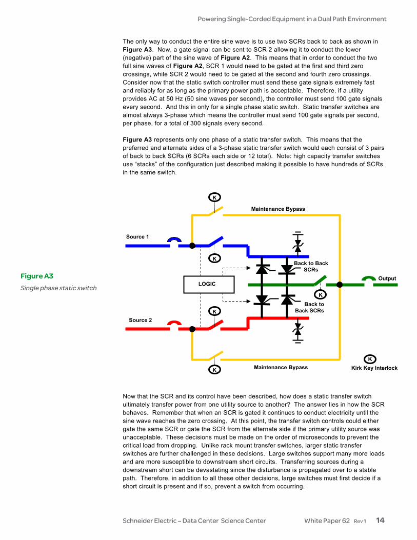
The only way to conduct the entire sine wave is to use two SCRs back to back as shown in Figure A3. Now, a gate signal can be sent to SCR 2 allowing it to conduct the lower (negative) part of the sine wave of Figure A2. This means that in order to conduct the two full sine waves of Figure A2, SCR 1 would need to be gated at the first and third zero crossings, while SCR 2 would need to be gated at the second and fourth zero crossings. Consider now that the static switch controller must send these gate signals extremely fast and reliably for as long as the primary power path is acceptable. Therefore, if a utility provides AC at 50 Hz (50 sine waves per second), the controller must send 100 gate signals every second. And this in only for a single phase static switch. Static transfer switches are almost always 3-phase which means the controller must send 100 gate signals per second, per phase, for a total of 300 signals every second. Figure A3 represents only one phase of a static transfer switch. This means that the preferred and alternate sides of a 3-phase static transfer switch would each consist of 3 pairs of back to back SCRs (6 SCRs each side or 12 total). Note: high capacity transfer switches use “stacks” of the configuration just described making it possible to have hundreds of SCRs in the same switch.
Now that the SCR and its control have been described, how does a static transfer switch ultimately transfer power from one utility source to another? The answer lies in how the SCR behaves. Remember that when an SCR is gated it continues to conduct electricity until the sine wave reaches the zero crossing. At this point, the transfer switch controls could either gate the same SCR or gate the SCR from the alternate side if the primary utility source was unacceptable. These decisions must be made on the order of microseconds to prevent the critical load from dropping. Unlike rack mount transfer switches, larger static transfer switches are further challenged in these decisions. Large switches support many more loads and are more susceptible to downstream short circuits. Transferring sources during a downstream short can be devastating since the disturbance is propagated over to a stable path. Therefore, in addition to all these other decisions, large switches must first decide if a short circuit is present and if so, prevent a switch from occurring.
Source 1
Source 2
Maintenance Bypass
Maintenance Bypass
K
K
K
K
K
K Kirk Key Interlock
Output LOGIC
Back to Back SCRs
Back to Back SCRs
Figure A3 Single phase static switch

Powering Single-Corded Equipment in a Dual Path Environment
Schneider Electric – Data Center Science Center White Paper 62 Rev 1 15
Electromechanical switches or automatic transfer switches (ATS): theory of operation Whereas static switches use SCRs, electromechanical switches use components called relays to switch between preferred and alternate power sources. Relays are based on the simple, economical operation of an electromagnet. The simplest electromagnet can be made by simply winding a wire around a nail and connecting the ends of the wire to a battery as shown in Figure A4. When the battery is connected to the wire, it causes current to flow in the coil which then produces a magnetic field. This magnetic field magnetizes the nail which can now be used to pick up other metal objects such as paper clips. This is the exact same principle that allows electromagnetic cranes to pick up cars in a junk yard except they require much more energy than a small battery.
So how does an electromagnet allow a relay to switch between power sources? Figure A5 provides some intuitive answers. A relay involves two circuits: the energizing circuit and the contact circuit. The electromagnet is on the energizing side and the relay contacts (C1 and C2) are on the contact side. Since the electromagnet attracts metal when energized, it is positioned near armature. An armature, in a relay, is the metal device that pivots between electrical contacts. When the electromagnet is energized, its magnetic force attracts and holds the armature against contact C1 thereby completing a circuit. However, when the electromagnet is deenergized, the armature needs a way of switching to contact C2. This is made possible by attaching a spring to the other end of the armature. Now, no matter what happens the armature is always in contact with either C1 or C2.
MAGNETIC FIELD CREATED
CONTACTS
COIL
ARMATURE
RELAY COIL TERMINALS
SPRING
PIVOT
COMMON TERMINAL
Figure A4 A simple electromagnet
Figure A5 Diagram of mechanical relay

Powering Single-Corded Equipment in a Dual Path Environment
Schneider Electric – Data Center Science Center White Paper 62 Rev 1 16
Like the static switch, an ATS also needs a controller to monitor the incoming power from both the primary and alternate power sources. However, the controls are much simpler given that they don’t need to send gate signals hundreds of times per second. Instead the control-ler simply monitors the condition of the primary and alternate power sources and decides when to energize and deenergize the relay.

Powering Single-Corded Equipment in a Dual Path Environment
Schneider Electric – Data Center Science Center White Paper 62 Rev 1 17
IT equipment and AC power: How does the switch-mode power supply (SMPS) work? How can IT equipment continue to operate during power interruptions? First consider how electricity is produced. Electricity is generally distributed as alternating current (AC) power from utilities and backup generators. AC voltage “alternates” between positive and negative — ideally as a perfect sine wave — passing through zero volts twice per cycle. It may not be noticeable to the naked eye, but a light bulb connected to utility voltage actually flickers 100 or 120 times per second (for 50 or 60 cycle AC) as the voltage crosses zero to change polarity. Does IT equipment also “turn off” 100 times or more per second as the line voltage changes polarity? Clearly, there is a problem here that IT equipment must solve. The way that virtually all modern IT equipment solves this problem is with a switch-mode power supply (SMPS).2 An SMPS first converts the AC voltage with all of its non-ideal components (voltage spikes, distortion, frequency variations, etc.) into flat DC (direct current). This process charges an energy storage element, called a capacitor, which stands between the AC input and the rest of the power supply. This capacitor is charged by the AC input in bursts twice per AC cycle when the sine wave is at or near its peaks (positive and negative) and discharges at whatever rate is required by the IT processing circuits downstream. The capacitor is designed to absorb these normal AC pulses along with anomalous voltage spikes continuously over its entire design life. So, unlike the flickering light bulb, IT equipment operates on a steady flow of DC instead of the pulsating AC of the utility grid. This is not quite the end of the story. Microelectronic circuits require very low DC voltages (3.3 V, 5 V, 12 V, etc.) but the voltage across the capacitor just mentioned can be as high as 400 V. The SMPS also converts this high-voltage DC to tightly regulated low-voltage DC outputs. In doing this voltage reduction, the SMPS performs another important function: it provides galvanic isolation. Galvanic isolation is a physical separation in the circuitry that serves two purposes. The first purpose is safety — protection against electric shock. The second purpose is protection against equipment damage or malfunction due to common-mode (ground-based) voltage or noise. Information about grounding and common-mode voltage is available in White Papers 9, Common Mode Susceptibility of Computers and 21, Neutral Wire Facts and Mythology. In the same way the SMPS “rides through” the intervals between peaks of the AC input sine wave, it also rides through other anomalies and brief interruptions in the AC supply. This is a feature important to IT equipment manufacturers because they want their equipment to function even in cases where a UPS is not present. No IT equipment manufacturer wants to stake their reputation for quality and performance on a power supply that cannot endure even the slightest AC line anomaly. This is particularly true for higher-grade networking and computing equipment, which is therefore typically built with higher quality power supplies. To demonstrate this ride-through ability, a typical computer power supply was heavily loaded and then its AC input was removed. The power supply’s output was monitored to determine how long acceptable output voltage continued to be delivered after the loss of AC input. The results are shown in Figure B1. The waveforms displayed are the power supply’s input voltage, input current, and DC output voltage.
2 “Switch-mode” refers to a feature of the power supply’s internal circuitry that is not related to this
discussion.
Appendix B
Common Mode Susceptibility of Computers
Related resource White Paper 9
Neutral Wire Facts and Mythology
Related resource White Paper 21

Powering Single-Corded Equipment in a Dual Path Environment
Schneider Electric – Data Center Science Center White Paper 62 Rev 1 18
Before being removed, the input voltage is the sine wave at the left in Figure B1. The input current — the spiked trace under the smooth voltage curve — consists of a short pulse at the positive peak of the input voltage and another short pulse at the negative peak. Only during these current pulses is the capacitor of the SMPS charged. The rest of the time, power is being drawn from the capacitor to provide power to the processing circuits. DC voltage at the output of the SMPS is the top trace in Figure B1. Notice that the output voltage remains tightly regulated for 18 milliseconds after the AC input is removed. Schneider Electric has tested a variety of power supplies from different computer and other IT equipment manufac-turers and found similar results. If the supplies are lightly loaded, the ride-through time will be much longer because the capacitor will be discharged more slowly.
Top Trace: Power supply low voltage DC output Middle Traces: Input voltage and current
Input voltage
Input current18 ms
DC output collapses
AC input interrupted
Figure B1 Power supply ride-through
After the AC goes away, a heavily loaded computer power supply’s output collapses, but only after a significant delay.