powerhouse - rytec doors · came with that door to install and/or ... 14.crowbar or pry bar. ......
TRANSCRIPT

R Y T E C
P.O. Box 403, One Cedar Parkway, Jackson, WI 53037 Phone: 262-677-9046 Fax: 262-677-2058
Rytec Website: www.rytecdoors.com, Rytec On-line store: www.rytecparts.com Rytec E mail: [email protected], Parts E mail: [email protected]
[Revision: April 12, 2016, R1600156-0, ©Rytec Corporation 2012]
Powerhouse Model SD®
Installation Manual


TABLE OF CONTENTS
PAGE
INTRODUCTION. . . . . . . . . . . . . . . . . . . . . . . . . . . . . . . . . . . . . . . . . . . . .1
HOW TO USE MANUAL . . . . . . . . . . . . . . . . . . . . . . . . . . . . . . . . . . . . . . . . . . . . . . 1
DOOR SERIAL NUMBER . . . . . . . . . . . . . . . . . . . . . . . . . . . . . . . . . . . . . . . . . . . . . 1
ITEMS IN SHIPPING CRATE . . . . . . . . . . . . . . . . . . . . . . . . . . . . . . . . . . . . . . . . . . 1
ELECTRICAL . . . . . . . . . . . . . . . . . . . . . . . . . . . . . . . . . . . . . . . . . . . . . . . . . . . . . . . 2
INSTALLATION . . . . . . . . . . . . . . . . . . . . . . . . . . . . . . . . . . . . . . . . . . . . . 2
MATERIAL, TOOLS, AND EQUIPMENT . . . . . . . . . . . . . . . . . . . . . . . . . . . . . . . . . 2
GENERAL ARRANGEMENT OF DOOR COMPONENTS . . . . . . . . . . . . . . . . . . . . 2
ADDITIONAL REQUIREMENTS . . . . . . . . . . . . . . . . . . . . . . . . . . . . . . . . . . . . . . . . 2
Labor and Site Requirements. . . . . . . . . . . . . . . . . . . . . . . . . . . . . . . . . . . . . 2
Forklift or Crane Requirements . . . . . . . . . . . . . . . . . . . . . . . . . . . . . . . . . . . 2
Electrician’s Responsibilities . . . . . . . . . . . . . . . . . . . . . . . . . . . . . . . . . . . . . 3
ANCHORING METHODS . . . . . . . . . . . . . . . . . . . . . . . . . . . . . . . . . . . . . . . . . . . . . 3
Block or Brick . . . . . . . . . . . . . . . . . . . . . . . . . . . . . . . . . . . . . . . . . . . . . . . . . 3
Metal Walls . . . . . . . . . . . . . . . . . . . . . . . . . . . . . . . . . . . . . . . . . . . . . . . . . . . . 3
LOCATING SIDE COLUMNS . . . . . . . . . . . . . . . . . . . . . . . . . . . . . . . . . . . . . . . . . . 3
SIDE COLUMNS AND HEAD ASSEMBLY . . . . . . . . . . . . . . . . . . . . . . . . . . . . . . . . 5
LIGHT CURTAIN (OPTIONAL) . . . . . . . . . . . . . . . . . . . . . . . . . . . . . . . . . . . . . . . . . 9
PHOTO EYES . . . . . . . . . . . . . . . . . . . . . . . . . . . . . . . . . . . . . . . . . . . . . . . . . . . . . 10
Testing Photo Eyes . . . . . . . . . . . . . . . . . . . . . . . . . . . . . . . . . . . . . . . . . . . . 11
LED (LIGHT EMITTING DIODE) . . . . . . . . . . . . . . . . . . . . . . . . . . . . . . . . . . . . . . . 11
THERMOSTAT CONTROL (OPTIONAL) . . . . . . . . . . . . . . . . . . . . . . . . . . . . . . . . 13
HOOD (OPTIONAL) . . . . . . . . . . . . . . . . . . . . . . . . . . . . . . . . . . . . . . . . . . . . . . . . . 13
FRONT MOUNT WINDBAR ASSEMBLY (OPTIONAL) . . . . . . . . . . . . . . . . . . . . . 16
Front Windbar Strap Clamp Assembly Mounting . . . . . . . . . . . . . . . . . . . . 16
Front Windbar Track Assembly Mounting . . . . . . . . . . . . . . . . . . . . . . . . . . 17
Front and Rear Windbar Strap & Drum Clamp Mounting . . . . . . . . . . . . . . 20
FRONT WINDBAR STRAP-DRUM INSTALLATION . . . . . . . . . . . . . . . . 21
REAR WINDBAR STRAP-DRUM INSTALLATION . . . . . . . . . . . . . . . . . 21
Front Windbar and Strap Final Assembly Mounting . . . . . . . . . . . . . . . . . . 22

REAR MOUNT WINDBAR ASSEMBLY (OPTIONAL) . . . . . . . . . . . . . . . . . . . . . . . 23
Anchoring Methods . . . . . . . . . . . . . . . . . . . . . . . . . . . . . . . . . . . . . . . . . . . . . 23
Retrofit Rear Mount Windbar Assembly . . . . . . . . . . . . . . . . . . . . . . . . . . . . 23
Locating Side Column Pullouts . . . . . . . . . . . . . . . . . . . . . . . . . . . . . . . . . . . 24
Rear Windbar Pullout Spreader Assembly . . . . . . . . . . . . . . . . . . . . . . . . . . 24
Side Column Pullouts and Pullout Header Assembly . . . . . . . . . . . . . . . . . 24
Rear Windbar Track Assembly Mounting . . . . . . . . . . . . . . . . . . . . . . . . . . . 26
Door Assembly Mounting to Rear Windbar Pullout Assembly . . . . . . . . . . 26
Rear Windbar and Strap Final Assembly Mounting . . . . . . . . . . . . . . . . . . . 27
REAR WINDBAR HOOD ASSEMBLY (OPTIONAL) . . . . . . . . . . . . . . . . . . . . . . . . 28
ADJUSTMENTS . . . . . . . . . . . . . . . . . . . . . . . . . . . . . . . . . . . . . . . . . . . . 29
DOOR LIMITS . . . . . . . . . . . . . . . . . . . . . . . . . . . . . . . . . . . . . . . . . . . . . . . . . . . . . 29
MANUAL DOOR PANEL MOVEMENT . . . . . . . . . . . . . . . . . . . . . . . . . . . . . . . . . . 29
STRAPPED WINDBAR ADJUSTMENT (OPTIONAL) . . . . . . . . . . . . . . . . . . . . . . 30
MISCELLANEOUS . . . . . . . . . . . . . . . . . . . . . . . . . . . . . . . . . . . . . . . . . . 32
FINAL CHECKS . . . . . . . . . . . . . . . . . . . . . . . . . . . . . . . . . . . . . . . . . . . . . . . . . . . 32
NOTES . . . . . . . . . . . . . . . . . . . . . . . . . . . . . . . . . . . . . . . . . . . . . . . . . . . .33

1
INTRODUCTION—HOW TO USE MANUAL
INTRODUCTION
The information contained in this manual will allow you
to install your Rytec Powerhouse SD® Door in a manner
that will ensure maximum life and trouble-free operation.
Any unauthorized changes to these procedures, or
failure to follow the steps as outlined, will
automatically void the warranty. Any changes to the
working parts, assemblies, or specifications as
written, which are not authorized by Rytec
Corporation, will also cancel the warranty. The
responsibility for the successful operation and
performance of this door lies with the owner.
DO NOT INSTALL, OPERATE, OR PERFORM
MAINTENANCE ON THIS DOOR UNTIL YOU READ
AND UNDERSTAND ALL THE INSTRUCTIONS IN
THIS MANUAL.
If you have any questions, contact your Rytec
representative or call the Rytec Technical Support
Department at 1-800-628-1909. Always refer to the
serial number of the door when calling your
representative or Customer Support. The location of
the serial number is on the left side of the head
assembly.
The wiring connections and schematics in this manual
are for general information purposes only. The actual
schematic for your custom installation is located in the
crate when the door is delivered.
HOW TO USE MANUAL
Throughout this manual, the following key words are
used to alert the reader to potentially hazardous
situations, or situations where additional information
to successfully perform the procedure is presented:
WARNING is used to indicate the potential
for personal injury, if the procedure is not
performed as described.
CAUTION is used to indicate the potential
for damage to the product or property
damage, if the procedure is not followed as
described.
IMPORTANT: IMPORTANT is used to relay
information CRITICAL to the
successful completion of the
procedure.
NOTE: NOTE is used to provide additional
information to aid in the performance of the
procedure or operation of the door, but not
necessarily safety related.
DOOR SERIAL NUMBER
The door serial number is located halfway up the left
side column.
IMPORTANT: When installing multiple doors of
the same model, verify & match
the serial numbers of all the
components for each door/ kit (i.e.
control panel, side columns, head
assembly, wind bar, etc.).
Figure 1
ITEMS IN SHIPPING CRATE
• Header Assembly
• Left and Right Side Columns
• Spreader Bar
• Control Panel
• Installation Manual
• Owner’s Manual
• Electrical Schematic (door specific)
• Windbar Assembly Kit-Front and/or Rear
(Optional)
• Hood Assembly (Optional)
• Small Parts Carton
IMPORTANT: Some door assemblies are
shipped in multiple crates. Every
Powerhouse door comes with a
door-specific electrical schematic.
Since the doors come in different
sizes and configurations, always
use the electrical schematic that
came with that door to install
and/or trouble- shoot problems.
Serial Number Location
A5800001
2
INSTALLATION—ELECTRICAL
ELECTRICAL
When working with electrical or electronic controls,
make sure that the power source has been locked
out and tagged according to OSHA regulations and
approved local electrical codes.
Qualified electricians must do all electrical wiring.
Wiring must meet all local, state, and federal codes.
Please check the documentation to determine the
specified voltage. Confirm that the power supply
meets the voltage required: 208V, 230/240V, or
460/480/575V. Voltage and fuses or breakers should
be checked before connecting to the main power
supply.
INSTALLATION
MATERIAL, TOOLS, AND EQUIPMENT
1. Threaded rod (ؽ-in.) and other various wall
anchor hardware and material. Concrete anchor
bolts (ؽ-in.). (See “ANCHORING METHODS”
on page 3)
2. Assorted shim stock.
3. Steel fish tape.
4. Double-sided tape (for attaching shims to wall).
5. Clamps (9” Minimum).
6. Electric and Hammer Drills.
7. Masonry drill bits (for ؽ-in. anchors).
8. Torx T40 Bit/Driver.
9. Carpenter’s level (4-ft. minimum length).
10. Carpenter’s square.
11. Ø⅜”, ؽ”, & “J” size drill bits. (J drill bit required/
included for retro fit installations)
12. ؾ” Step drill bit.
13. Hammer or mallet and block of wood.
14. Crowbar or pry bar.
15. Assorted hand tools (pliers, tape measure, etc.).
16. Socket and wrench sets.
17. Water level, line level, laser level, or transit.
18. Scissors lift and/or 2 ladders (taller than door
opening).
19. Forklift (see “Forklift or Crane Requirements”).
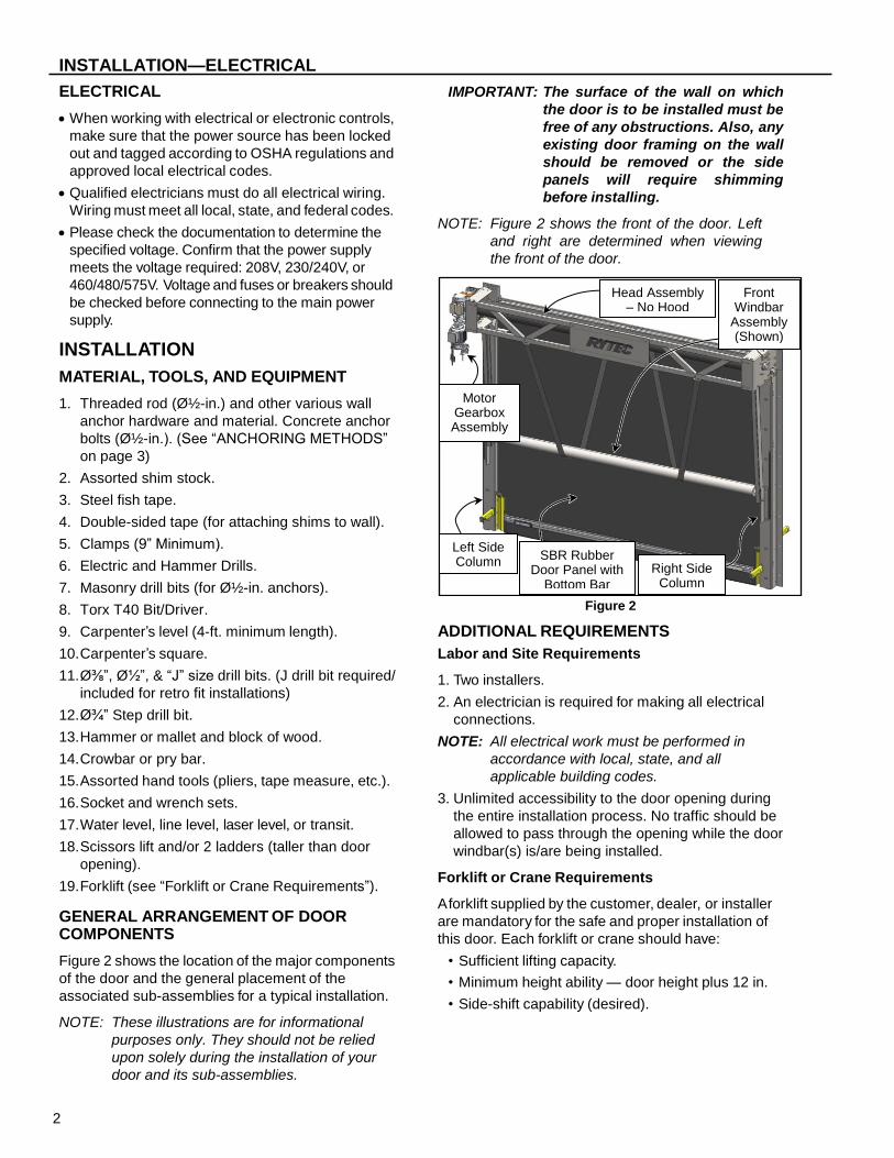
GENERAL ARRANGEMENT OF DOOR COMPONENTS
Figure 2 shows the location of the major components
of the door and the general placement of the
associated sub-assemblies for a typical installation.
NOTE: These illustrations are for informational
purposes only. They should not be relied
upon solely during the installation of your
door and its sub-assemblies.
IMPORTANT: The surface of the wall on which
the door is to be installed must be
free of any obstructions. Also, any
existing door framing on the wall
should be removed or the side
panels will require shimming
before installing.
NOTE: Figure 2 shows the front of the door. Left
and right are determined when viewing
the front of the door.
Figure 2
ADDITIONAL REQUIREMENTS
Labor and Site Requirements
1. Two installers.
2. An electrician is required for making all electrical
connections.
NOTE: All electrical work must be performed in
accordance with local, state, and all
applicable building codes.
3. Unlimited accessibility to the door opening during
the entire installation process. No traffic should be
allowed to pass through the opening while the door
windbar(s) is/are being installed.
Forklift or Crane Requirements
A forklift supplied by the customer, dealer, or installer
are mandatory for the safe and proper installation of
this door. Each forklift or crane should have:
• Sufficient lifting capacity.
• Minimum height ability — door height plus 12 in.
• Side-shift capability (desired).
Right Side Column
Left Side Column
SBR Rubber Door Panel with
Bottom Bar
Head Assembly – No Hood
Motor Gearbox Assembly
Front Windbar
Assembly (Shown)

3
INSTALLATION—ANCHORING METHODS
Electrician’s Responsibilities
For complete details on the responsibilities of the
electrician, refer to the wiring diagram and manual that
were shipped with the control drive.
ANCHORING METHODS
Correct anchoring of the side columns and head
assembly to the wall is important for the smooth and
safe operation of the door. The wall material should
be strong enough to support the weight to lateral load
of the door assembly and all wall anchors.
Figure 3 shows an anchoring method for various
types of walls. Use the method that is best suited for
your particular installation site.
All necessary anchoring hardware and material
required for the installation of this door are the
responsibility of the door owner. If you have any
questions, call your Rytec representative or the Rytec
Technical Support Department at 1-800-628-1909.
NOTE: Use ع/₂-in. threaded through bolts or threaded rods to anchor the door to all wall applications. Rytec does not recommend
mounting the door to wood or insulated wall
without additional structural reinforcements.
Consult with structural engineer or architect.
Block or Brick
Figure 3
Metal
When installing the Powerhouse SD door to a metal structure, use 4-in. welds every 16 inches on both
sides of the side columns. A certified welding
professional should perform this type of installation.
(See Figures 4 and 5)
NOTE: The door assembly, walls, and building
structure MUST BE properly grounded.
Use bar clamps and simply use small
tack welds to hold side column in
position. DO NOT weld permanently into
place until you’ve verified that the door is
plumb.
Figure 4
Figure 5
LOCATING SIDE COLUMNS
1. Locate the layout drawing of the door. It should be
attached to the small parts carton. This drawing
identifies the production width of your door.
2. Using the centerline as a reference point, lay out
and mark half of the door’s production width along
the floor. (See Figure 6)
Block/Brick Wall
Crush Plate (¹/₂-in. thick, 6-in. x 8-in.
Steel)
“C” Channel or Side Column
Through Bolt or Threaded Rod
Backing Nut
A 4-inch Weld Is Placed Every
16 Inches
A5800059
or Threaded Rod
A5800058
or Threaded Rod
A 4-inch Weld Is Placed Every
16 Inches

4
INSTALLATION—LOCATING SIDE COLUMNS
Figure 6
3. With a carpenter’s square placed against the wall,
mark both sides of the door along the floor. Extend
the line along each edge.
4. Check the floor for level across the door opening.
The floor must be level within 0.12 in. from side-to-
side. If one side of the opening is higher than the
other, a shim under the low side column will be
required.
Figures 7 and 8 show two recommended methods
that can be used to ensure level side column
installation.
NOTE: Contact the Rytec Technical Department
if the floor is more than 1 in. out of level.
Figure 7
Figure 8
5. Use a plumb bob or carpenter’s level to check the
wall for plumb in the areas where the side columns
are to be mounted. Also, inspect the wall for any
obstructions.
If the wall is not plumb, use shims. If you find an
obstruction, remove it or shim the column to avoid
the obstruction. (See Figure 9)
Figure 9
NOTE: If the door requires more than ¹/₂ in. to
shim around the wall obstruction, longer
anchors will be required.
Overall Width of Door Opening
Half Width of Door Opening
A0500001
or Threaded Rod
Centerline of Opening
This Dimension Must Be Equal on Both Sides
of the Door Opening
Line Level
Shim Plate (As Required) A0500003
or Threaded Rod
This Dimension Must Be Equal on Both Sides
of the Door Opening
Line Level
Shim Plate (As Required) A0500003
or Threaded Rod
Uneven Wall
Shim
A5800005
or Threaded Rod

5
INSTALLATION—SIDE COLUMNS AND HEAD ASSEMBLY
SIDE COLUMNS AND HEAD ASSEMBLY
The side columns come completely assembled. They
are installed with LED and light curtain assemblies
(optional) at the factory to make the routing and
connecting of cables and wires more efficient.
NOTE: The side columns come with preset
anchor points for your custom door
height. DO NOT add additional anchor
points as this will void the door warranty.
Contact the Rytec Technical Support
Department at1-800-628-1909 for
engineering support.
Production width is measured from the
inner side columns. The door must be
installed centered on the opening and in
most instances, flush with the wall jamb.
Figure 10
1. Remove the right side column from the shipping
crate.
IMPORTANT: It is critical that the side columns
are mounted square and plumb
with the wall, and level across the
door opening. Using a 4-ft. level
and carpenter’s square will help
ensure the columns are correctly
set. Place shims where necessary.
In addition, the use of bar clamps
will allow you to temporarily
secure the columns to the wall,
while allowing you to make slight
adjustments during the
installation process.
Before drilling any holes, ensure there are no
electrical wires, water pipes, gas lines, etc., buried
in the floor or hidden in the wall.
2. Place the right side column against the wall and
align with the marks on the floor.
NOTE: In many instances the jamb may not be
plumb, square or level.
3. Once the side column is set plumb and square, bar
clamp it to the wall. (See Figure 11)
Figure 11
4. Anchor the side column (See “ANCHORING
METHODS” on page 3). DO NOT tighten the
anchors completely at this time - they will be
tightened later on after the head assembly is
installed. (See Figure 12)
Left Side WallJamb
Right Side Column
Production Width
A5800051
Right Side WallJamb
Right Side Column
Wall
A5800004

6
INSTALLATION—SIDE COLUMNS AND HEAD ASSEMBLY
Figure 12
NOTE: Use all anchor holes to anchor the side
columns to the wall.
IMPORTANT: Use / -in. epoxy-filled and/or
vibration resistant anchors for
concrete walls. Use through bolts
or threaded rods for brick walls.
5. Install left side column in the same manner as the
right.
6. Install rear spreader assembly between the two
side columns using four ¹/₂ x 1-in. hex head cap
screws and ¹/₂-in. lock washers. (See Figure 13)
Figure 13
7. With both columns set, clamped down, and snugly
anchored in place, check the overall squareness of
each column.
Compare the diagonal measurements and the
upper and lower horizontal measurements across
the columns. The columns are square and parallel
when the diagonal measurements are equal and
the horizontal measurements are equal. (See
Figure 14)
NOTE: If either column requires slight
repositioning (when the difference of
either comparison is greater than ¹/₄ in.),
use a block of wood and a mallet to
nudge the column into position.
Figure 14
8. Install anchor into rear spreader assembly. (See
Figure 15)
Figure 15
LED Light
Wall Anchor A5800006
Rear Spreader Assembly
A5800007
Cap Screw
Washer
Wall
A5800151
Rear Spreader Assembly Wall Anchor
A5800008

7
INSTALLATION—SIDE COLUMNS AND HEAD ASSEMBLY
9. Attach head assembly to the lifting device:
a. Attach an appropriate rated strap or chain to the
lifting lugs of the head assembly. (See Figure 16)
NOTE: The lifting lugs are manufactured at a 45°
angle and should not be modified. When
using chains or straps to lift the head
assembly into place, the angle cannot be
less than 45°. Anything less than that will
cause the assembly to bow, and improper
alignment and fit will result.
Before fully lifting head assembly into
position, test the strap angle on the head
assembly. If end plates begin to bow
inward, increase the strap angle.
Figure 16
b. Secure the head assembly to a forklift or other
suitable lifting device. (See Figure 17)
NOTE: The wooden cradle supports the head
assembly during shipping. The wooden
cradle can be used to lift the head
assembly into position when overhead
clearance is unavailable. If the wooden
cradle is used to lift the head assembly
into position caution must be taken in
lifting the assembly safely. The preferred
method of lifting the head is from the top
utilizing the lifting lugs.
IMPORTANT: When lifting from the bottom, the
load is heavy and out in front
away from the fork truck. Use
caution when lifting.
Figure 17
10. Lift into position and align head assembly with
the side columns. Install washers, lock washers,
and cap screws. (See Figure 18 and Figure 19)
IMPORTANT: There are three sizes of head
assemblies for the Powerhouse
SD door.
• A-Size (13.00 in.) Head
• B-Size (18.50 in.) Head
• C-Size (22.50 in.) Head
The A-Size requires six washers,
lock washers, and cap screws to
attach the head assembly to the
side columns. The B-Size and C-
Size require eight.
NOTE: The motor/gearbox is factory installed to
the head assembly. Use extreme care
when lifting and attaching the head
assembly to the side columns.
45° - 90°
Chain
A5800053
45° -
90°
Forklift
A5800053
Wooden Cradle
Head Assembly

8
INSTALLATION—SIDE COLUMNS AND HEAD ASSEMBLY
Figure 18
Figure 19
11. Using a carpenter’s level (4-ft. minimum length),
check that the head assembly is level and tighten
all hardware and anchors.
12. Tighten all anchors and associated hardware.
13. OPTIONAL: The lifting lug and shipping bar are
used to install the door. These pieces can be
removed if there is a interference problem. (See
Figure 18)
NOTE: See “HOOD (OPTIONAL)” on pages 13
and 28 regarding lifting lug and shipping
bar.
14. Check and adjust the routing of the bottom bar
and door panel over the idler roller. (See Figure
20)
Figure 20
IMPORTANT: Prior to installing the hood
assembly or switching power on
for the first time, make sure all
wires and cables are properly
routed and secure. Wires and
cables should not interfere with
any moving parts.
Figure 21
Install Washers, Lock Washers, and Cap Screws
A5800009
Lifting Lug
Motor Installation Hardware (Factory Installed)
A5800154
Install Washers, Lock Washers, and Cap Screws
Shipping Bar
A5800009
Guide Roller
Door Panel
A5800009
Proper Cable Routing To System 4 Control Panel
9
INSTALLATION—LIGHT CURTAIN (OPTIONAL)
LIGHT CURTAIN (OPTIONAL)
IMPORTANT: Light curtains are standard on the
Powerhouse SD model doors.
Standard photo eyes are optional.
(See “PHOTO EYES (optional)” on
page 10)
The Powerhouse SD door is equipped with a set of
light curtains. One side column will contain the
transmitter module and the other contains the
receiver module. The transmitter and receiver have
both been factory installed and cabled in the side
columns. The cables exit the side columns at the top.
The purpose of the light curtains is to hold the door
open if a vehicle, person, or any object is in the path
of the light curtain beam.
The light curtain is not active when the door is
closed.
This system consists of one pair of non-adjustable
emitter and receiver module. There are no gain or
sensitivity settings.
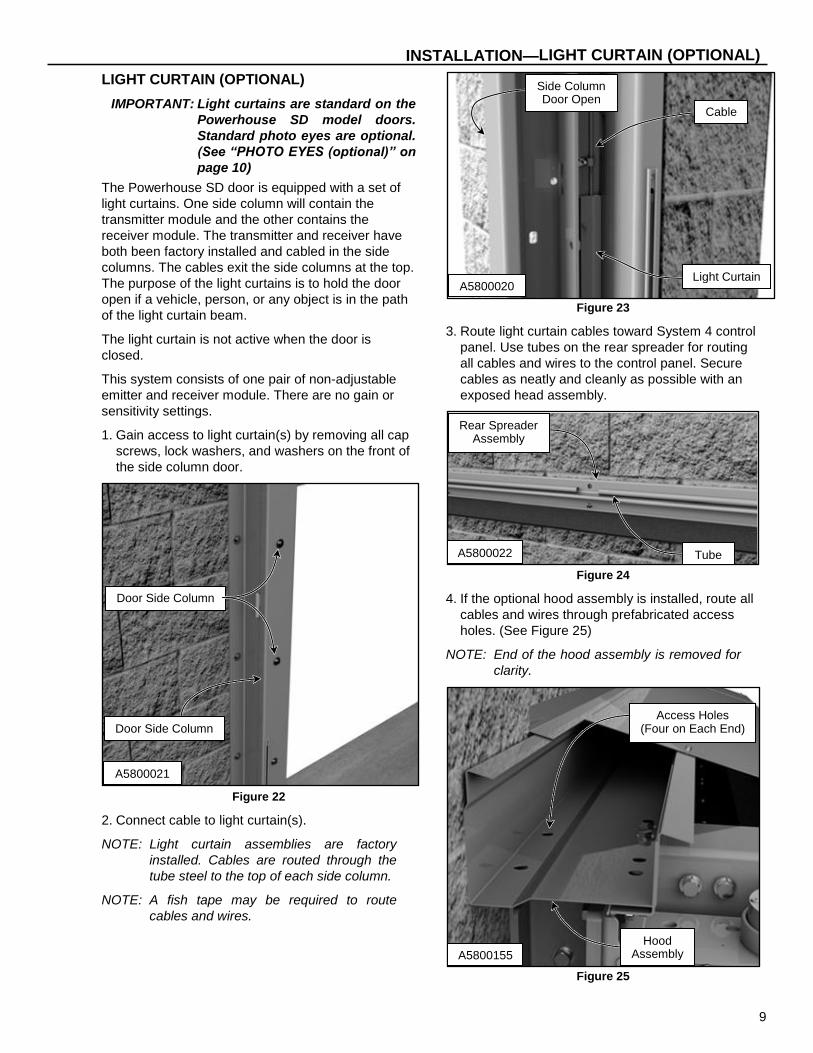
1. Gain access to light curtain(s) by removing all cap
screws, lock washers, and washers on the front of
the side column door.
Figure 22
2. Connect cable to light curtain(s).
NOTE: Light curtain assemblies are factory
installed. Cables are routed through the
tube steel to the top of each side column.
NOTE: A fish tape may be required to route
cables and wires.
Figure 23
3. Route light curtain cables toward System 4 control
panel. Use tubes on the rear spreader for routing
all cables and wires to the control panel. Secure
cables as neatly and cleanly as possible with an
exposed head assembly.
Figure 24
4. If the optional hood assembly is installed, route all
cables and wires through prefabricated access
holes. (See Figure 25)
NOTE: End of the hood assembly is removed for
clarity.
Figure 25
A5800021
Door Side Column
Door Side Column
A5800020 Light Curtain
Side Column Door Open
Cable
Rear Spreader Assembly
Tube A5800022
Access Holes (Four on Each End)
Hood Assembly A5800155

10
INSTALLATION—PHOTO EYES
PHOTO EYES
The disconnect must be in the OFF position and
properly locked and tagged before proceeding
and performing the following procedures.
The photo eyes are provided as a safety feature. If
the photo eyes are installed correctly, any object in
the path of the photo eye beam while the door is
closing will cause the door to reverse direction and
remain in the fully open position until the obstruction
is removed.
The transmitter and receiver can be identified in two
ways. The transmitter is designated SMT 3000 on
the white label or by a single green light that comes
on at the clear end of the transmitter. (See Figure 26)
The receiver is designated SMR 3215 on the white
label or by a yellow light that illuminates only when it
is in proper alignment with the transmitter. (See
Figure 27)
NOTE: When the cable is connected to the photo
eye, there is only a ¹/₄-inch window to see
the green or yellow LED light.
Figure 26
Figure 27
The front and rear photo eyes, their required wire
cables, and mounting brackets are located in the
small parts carton. You must provide the hardware to
install the brackets on your particular wall.
NOTE: The front set of eyes is to be located on
the wall, adjacent to the front side of the
door. Each eye must be located 8–12 in.
above the floor and as close to the door
as possible. They must also be mounted
directly across from each other. (See
Figure 28)
Figure 28
Transmitter Module
Designation Power Light
(Green)
Receiver Module
Designation Alignment Light
(Yellow)
Photo Eyes 6” - 8”
Off Floor
A7700054
A2500259
A2500258
11
INSTALLATION—LED (LIGHT EMITTING DIODE)
1. After the mounting brackets are in place, install the
transmitter module in the left bracket and the
receiver module in the right bracket.
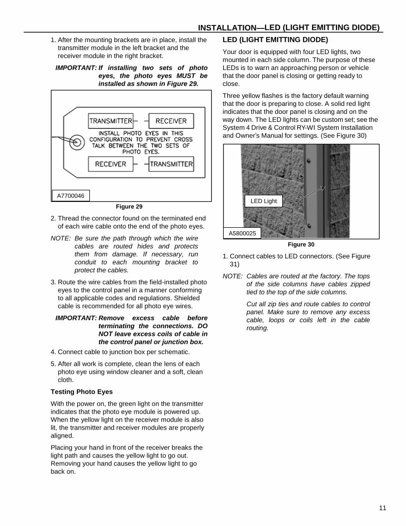
IMPORTANT: If installing two sets of photo
eyes, the photo eyes MUST be
installed as shown in Figure 29.
Figure 29
2. Thread the connector found on the terminated end
of each wire cable onto the end of the photo eyes.
NOTE: Be sure the path through which the wire
cables are routed hides and protects
them from damage. If necessary, run
conduit to each mounting bracket to
protect the cables.
3. Route the wire cables from the field-installed photo
eyes to the control panel in a manner conforming
to all applicable codes and regulations. Shielded
cable is recommended for all photo eye wires.
IMPORTANT: Remove excess cable before
terminating the connections. DO
NOT leave excess coils of cable in
the control panel or junction box.
4. Connect cable to junction box per schematic.
5. After all work is complete, clean the lens of each
photo eye using window cleaner and a soft, clean
cloth.
Testing Photo Eyes
With the power on, the green light on the transmitter
indicates that the photo eye module is powered up.
When the yellow light on the receiver module is also
lit, the transmitter and receiver modules are properly
aligned.
Placing your hand in front of the receiver breaks the
light path and causes the yellow light to go out.
Removing your hand causes the yellow light to go
back on.
LED (LIGHT EMITTING DIODE)
Your door is equipped with four LED lights, two
mounted in each side column. The purpose of these
LEDs is to warn an approaching person or vehicle
that the door panel is closing or getting ready to
close.
Three yellow flashes is the factory default warning
that the door is preparing to close. A solid red light
indicates that the door panel is closing and on the
way down. The LED lights can be custom set; see the
System 4 Drive & Control RY-WI System Installation
and Owner’s Manual for settings. (See Figure 30)
Figure 30
1. Connect cables to LED connectors. (See Figure
31)
NOTE: Cables are routed at the factory. The tops
of the side columns have cables zipped
tied to the top of the side columns.
Cut all zip ties and route cables to control
panel. Make sure to remove any excess
cable, loops or coils left in the cable
routing.
A7700046
A5800025
LED Light

12
INSTALLATION—LED (LIGHT EMITTING DIODE)
NOTE: Head assembly has been removed to
show clarity of the LED connectors. (See
Figure 31)
Figure 31
2. Route LED light cables toward the System 4
control panel. Use tubes on the rear spreader for
routing all cables and wires to the control panel.
(See Figure 32)
NOTE: Secure cables as needed.
NOTE: A fish tape may be required to route cables
and wires.
Figure 32
3. If the optional hood assembly is installed, route all
cables and wires through prefabricated access
holes. (See Figure 33)
NOTE: End of the hood assembly is removed for
clarity.
Figure 33
A5800026
Cables from LED Lights
Left Side Column
A5800022
Rear Spreader
Tube
A5800155
Access Holes (Four on Each End)
Hood Assembly

13
INSTALLATION—THERMOSTAT CONTROL (OPTIONAL)
THERMOSTAT CONTROL (OPTIONAL)
An optional thermostat control is available for the
Powerhouse SD door. The thermostat controls a
trickle charge to the motor to heat the motor
windings. Rytec part number #R00112019. Contacts
close at 32°F (0°C), open at 50°F (10°C). When
contacts are closed the trickle charge travels to the
motor and keeps the windings warm. If the
thermostat has been ordered at installation reference
the electrical schematics for connections.
HOOD (OPTIONAL)
The hood is an option for the Powerhouse SD door. It
is built at the factory and delivered separately to the
door site. The installer will have to assemble and
install the hood assembly.
The disconnect must be in the OFF position and
properly locked and tagged before proceeding
and performing the following procedures.
1. Remove and discard the shipping bar and both
lifting lugs from the head assembly if this hasn’t
already been done. Save the hardware from the
shipping bar. (See Figure 34)
NOTE: If these items were already discarded,
then remove the hardware that attached
the shipping bar to the head assembly.
Figure 34
2. Install the hood spreader with the hardware that
was removed from the shipping bar. (See Figure
35)
Figure 35
3. Install two front hood pieces onto the front truss
assembly. Use ¹/₄-14 x ³/₄-in. hex washer self-
drilling screws. (See Figure 36)
NOTE: The front hood pieces can vary in size,
both in length and height. The quantity of
hardware to do the assembly will vary,
depending on the size of the head.
Figure 36 A5800009
Lifting Lug Shipping Bar
A5800012
Hardware Removed From Shipping Bar
Hood Spreader
A5800013
Hardware Front Hood
Assembly

14
INSTALLATION—HOOD (OPTIONAL)
4. Attach right head assembly end cover onto the
front truss assembly. Use ¹/₄-14 x ³/₄-in. hex
washer self- drilling screws. (See Figure 37 and
Figure 38)
Figure 37
Figure 38
NOTE: Right end cover wall anchor installation.
5. Attach the left head assembly end cover onto the
front truss assembly. Use ¼-14 x ¾-in. hex washer
self-drilling screws. (See Figure 39 and Figure 40)
Figure 39
Figure 40
NOTE: Left end cover wall anchor installation.
A5800014
Hex Washer Self-Drilling Screws
Right End Cover
A5800015
Hood to Wall Anchor Points
A5800018
Hex Washer Self-Drilling Screws
Left End Cover
A5800019
Hood to Wall Anchor Points
15
INSTALLATION—HOOD (OPTIONAL)
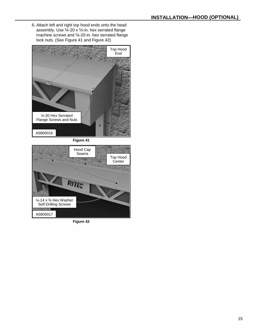
6. Attach left and right top hood ends onto the head
assembly. Use ¼-20 x ½-in. hex serrated flange
machine screws and ¼-20-in. hex serrated flange lock nuts. (See Figure 41 and Figure 42)
Figure 41
Figure 42
A5800016
¼-20 Hex Serrated Flange Screws and Nuts
Top Hood End
A5800017
¼-14 x ¾ Hex Washer Self-Drilling Screws
Top Hood Center
Hood Cap Seams
16
INSTALLATION—FRONT MOUNT WINDBAR ASSEMBLY (OPTIONAL)
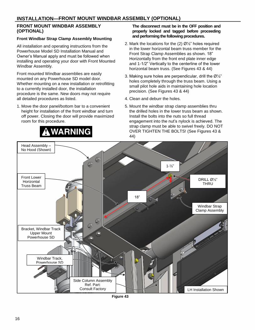
FRONT MOUNT WINDBAR ASSEMBLY (OPTIONAL)
Front Windbar Strap Clamp Assembly Mounting
All installation and operating instructions from the
Powerhouse Model SD Installation Manual and
Owner’s Manual apply and must be followed when
installing and operating your door with Front Mounted
Windbar Assembly.
Front mounted Windbar assemblies are easily
mounted on any Powerhouse SD model door.
Whether mounting on a new installation or retrofitting
to a currently installed door, the installation
procedure is the same. New doors may not require
all detailed procedures as listed.
1. Move the door panel/bottom bar to a convenient
height for installation of the front windbar and turn
off power. Closing the door will provide maximized
room for this procedure.
The disconnect must be in the OFF position and
properly locked and tagged before proceeding
and performing the following procedures.
2. Mark the locations for the (2) ؽ” holes required
in the lower horizontal beam truss member for the
Front Strap Clamp Assemblies as shown. 18”
Horizontally from the front end plate inner edge
and 1-1/2” Vertically to the centerline of the lower
horizontal beam truss. (See Figures 43 & 44)
3. Making sure holes are perpendicular, drill the ؽ”
holes completely through the truss beam. Using a
small pilot hole aids in maintaining hole location
precision. (See Figures 43 & 44)
4. Clean and deburr the holes.
5. Mount the windbar strap clamp assemblies thru
the drilled holes in the lower truss beam as shown.
Install the bolts into the nuts so full thread
engagement into the nut’s nylock is achieved. The
strap clamp must be able to swivel freely. DO NOT
OVER TIGHTEN THE BOLTS! (See Figures 43 &
44)
Figure 43
Side Column Assembly Ref. Part:
Consult Factory
Head Assembly – No Hood (Shown)
Ref. Part: #R1600040-XX00
Windbar Strap Clamp Assembly
Ref. Part: #R1600862-0
Front Lower Horizontal
Truss Beam
Windbar Track, Powerhouse SD
Ref. Part: #R1600856-0
Bracket, Windbar Track Upper Mount
Powerhouse SD Ref. Part: #R1600860-0
LH Installation Shown
DRILL ؽ” THRU
1-½”
18”

17
INSTALLATION—FRONT WINDBAR STRAP CLAMP ASSEMBLY MOUNTING
Figure 44
Front Windbar Track Assembly Mounting
1. Move the door panel/bottom bar to the closed
position for installation of the front windbar and
turn off power. Closing the door will provide
maximized room for the following procedures.
The disconnect must be in the OFF position and
properly locked and tagged before proceeding
and performing the following procedures.
2. Mark the locations for the (4) Ø⅜” holes required
in the Head Assembly Bottom Plates for the
Upper Windbar Track Mounting Bracket as shown
when necessary (retrofit installations). (See
Figures 45 & 46)
3. Making sure holes are perpendicular and true to
the plates, drill the Ø⅜” holes completely through
the Bottom Plates. Using a small pilot hole aids in
maintaining hole location precision.
4. Clean and deburr the holes.
5. Mount the Upper Windbar Track Mounting
Bracket to the Head Assembly Bottom Plates as
shown. Screw the bolts into the nuts so full thread
engagement is achieved. Do not tighten the
brackets in place yet. They will need adjustment
later. (See Figure 46)
6. Hang and fasten the Windbar Tracks from the
Upper Windbar Track Mounting Brackets with the
hardware shown. (See Figure 46)
IMPORTANT: The track must be oriented with
the thick face of the track facing
away from the door panel as
shown.
The track’s inside face/edge must be mounted
flush with the inside edge of the Side Column.
Screw the bolts into the nuts so full thread
engagement is achieved. Do not tighten the
brackets in place yet. They will need adjustment
later. (See Figures 45 and 47)
Screw, ½-13 x 2-3/4” Hex*
Washer, ؽ” *
Nut, ½-13 Hex Nylock*
Screw, 3/8-16 x 1-1/4 Hex Flange*
Bracket, Windbar Strap Clamp* Nut, 3/8 -16 Hex
Flanged Lock*
Clamp, Tension Strap*
LH Installation Shown
*Parts contained in Assy. #R1600862-0
Hole, ؽ”

18
INSTALLATION—FRONT WINDBAR TRACK ASSEMBLY MOUNTING
Figure 45
Figure 46
Head Assembly Bottom Plate
Bracket, Upper Windbar Track Mount
Powerhouse SD Ref. Part: #R1600860-0
Windbar Track, Powerhouse SD
Ref. Part: #R1600856-0
Side Column Assembly, Powerhouse SD
Ref. Part: Consult Factory
Bracket, Upper Windbar Track Mount
Powerhouse SD (LH Installation Shown) Ref. Part: #R1600860-0
Screw, 3/8-16 x 1-1/4 Hex Ref. Part:
#R5550137-0Z01
Washer, Ø⅜” Flat Ref. Part:
#R0555146
Washer, Ø⅜” Lock Ref. Part:
#R0554118
Nut, 3/8-16 Hex Ref. Part:
#R0553091
Head Assembly Bottom Plate
Windbar Track inside face must be flush with
Side Column Ref. Part: #R1600856-0
LH Installation Shown
LH Installation Shown
DRILL Ø⅜ HOLE (2) PLACES ON EACH SIDE
1-1/2”
5”
1-3/4”

19
INSTALLATION—FRONT WINDBAR TRACK ASSEMBLY MOUNTING
Figure 47
7. Remove and replace the ⅜-16 x 1.00 Side
Column Cover screws just above and below the
ends of the windbar tracks with the 1-1/4” long
screws supplied with the windbar assembly kit.
Also replace the ؾ” flat washers with the ones
supplied in the windbar assembly kit. (See Figure
48)
8. Mount the Lower Windbar Track Brackets to the
side column covers using the longer screws
supplied from the kit. (See Figure 48)
9. Butt the windbar tracks up against the side
column covers and the lower mounting bracket as
shown. (See Figure 49)
10. Mark the center of the Track Bracket lower
mounting hole and drill a ؾ” hole thru the Lower
Mounting Brackets as shown. (See Figures 48 &
49)
11. Fasten the Windbar Track to the Lower Mount
with the fasteners as shown. The threaded portion
of the ¾” bolts must be mounted toward the inside
of the tracks. (See Figures 48, & 50)
12. Check the inside width between the Windbar
Tracks. It should measure the same as the door
width.
Figure 48
Figure 49
Bracket, Upper Windbar Track Mount
Powerhouse SD Ref. Part: #R1600860-0
Screw, 3/4-10 x 2-1/4 Hex Ref. Part:
#R5550270-0Z01
Washer, ؾ” Flat Ref. Part:
#R0555287
Nut, ¾”-10 Hex Lock Ref. Part:
#R0553094
Windbar Track, Powerhouse SD
Ref. Part: 1600856-0
Windbar Track reinforcement must face
away from door panel
Windbar Track
LH Installation Shown
Lower Windbar
Track Mount
LH Installation Shown
ؾ” hole
LH Installation Shown
Screw, 3/4-10 x 2-1/4 Hex Ref. Part: #R5550270-0Z01
Screw, 3/8-16 x 1-1/4 Hex Ref. Part:
#R5550137-0Z01
Washer, Ø⅜” Flat Ref. Part: #R0555146
Washer, Ø⅜” Lock Ref. Part: #R0554118
Washer, ؾ” Flat Ref. Part:
#R0555287
Nut, ¾”-10 Hex Lock Ref. Part:
ؾ” hole
Door Panel

20
INSTALLATION-FRONT AND REAR WINDBAR STRAP AND DRUM CLAMP MOUNTING
Figure 50
Front and Rear Windbar Strap & Drum Clamp
Mounting
1. Completely unroll the door panel/bottom bar so
that you can gain full access to the drum for
installation of the front windbar straps. Turn off
the door’s power. (See Figure 51)
The disconnect must be in the OFF position and
properly locked and tagged before proceeding
and performing the following procedures.
NOTE: New doors may not need holes drilled in the
field. Doors manufactured prior to this
revision will require holes to be drilled per
steps 2-4.
2. Place a Windbar Strap Clamp directly against the
panel drum just below the door panel edge (about
¼”) as shown on either side of the drum center.
Center the (2) strap clamps 4” on either side of
the drum’s center. If the clamp centers are the
same distance as an existing panel mounting
screw, each clamp must be moved out from the
drum’s center an additional 4”. The Windbar Strap
Clamps must straddle the panel mounting screws
as shown. (See Figure 52)
3. Mark each of the Windbar Strap Clamp centers
on the Panel Drum. Create a pilot hole for each
hole on these center marks.
4. Using a “J” size drill bit, finish drill (4) true and
perpendicular “J” size (Ø.277”) holes for the strap
clamps fasteners. (See Figure 52)
IMPORTANT: Use only a “J” size drill bit. Do
not tilt or angle the drill. Holes
must be true formed.
Figure 51
Figure 52
5. While aligning the screws perpendicular and true
to the drum, use a drill w/ a Torx T40 driver bit to
drive the 5/16-18 x 2.00 tapping screws into the
“J” size drilled holes and tap the screw threads.
Do not strip the tapped hole threads.
6. After all the screw mounting holes have been
tapped and threaded, remove the screws and
clamps.
7. Stack the Windbar Strap Clamps over the
mounting holes with the countersink of the holes
in the outer strap clamp facing out and away from
the drum. (See Figure 53)
LH Installation Shown
Windbar Track, Powerhouse SD
Ref. Part: #R1600856-0
Unrolled Door Panel to expose Drum/Panel Fasteners
Panel Drum
Door Panel
Door Panel to Drum Mounting Fasteners
Lower Windbar Track Mount Bracket
Ref. Part: #R1600861-0
4.00”-8.00”
¼”
Panel Edge
Panel Drum
Idler Drum
Panel
“J” size hole
Tapping Screw 5/16-18 x 2.00
Ref. Part: #R5550185-0Z01
Clamp, Tension Strap Ref. Part: #R0203138

21
INSTALLATION-FRONT AND REAR WINDBAR STRAP AND DRUM CLAMP MOUNTING
Figure 53
8. Insert the screws again through the clamps but do
not tighten leaving some clearance for inserting
the straps. (See Figure 53)
9. If both front and rear windbars are used, install
the front as shown. The rear windbar straps must
be installed between the next set of Panel-Drum
Mounting Fasteners out from the drum center.
(See Figures 52 and 53)
NOTE: Windbar Strap(s) may be factory
installed. If they are not, install them
according to the following steps.
FRONT WINDBAR STRAP-DRUM INSTALLATION
a. Loosen the existing panel/drum mounting
fasteners (screws and washers) within the area
of the mounting strap that is directly over, and
adjacent to, the windbar straps as well as
between the strap clamps. Loosen them just
enough to allow installing the straps. (See Figure
53)
b. Place a Windbar Strap on the front side of the
door panel and pull one end up, between the
panel and drum, between the two clamps. (See
Figures 53 and 54)
c. Wrap the strap one (1) full wrap around the
drum, pulling the strap end under both clamps.
(See Figures 53 and 54)
d. Pull the strap end back between the two clamps
in the opposite direction and under the strap.
Leave approximately 6” of excess strap pulled
through the clamps. (See Figures 53 and 54)
REAR WINDBAR STRAP-DRUM INSTALLATION
a. Loosen the existing panel/drum mounting
fasteners (screws and washers) within the area
of the mounting strap that is directly over, and
adjacent to, the windbar straps as well as between
the strap clamps. Loosen them just enough to
allow installing the straps. (See Figure 53)
Figure 54
b. Place a Windbar Strap on the rear side of the
door panel and pull one end up and over the
panel and drum, then between the two clamps.
(See Figure 53)
c. Wrap the strap one (1) additional full wrap
around the drum, pulling the strap end under the
panel and drum and under both clamps. (See
Figures 53 and 55)
Strap, Windbar Ref. Part:
#R1600864-0
Clamp, Tension Strap Ref. Part: #R0203138
Clamp, Countersunk Tension Strap
Ref. Part: #R1600893-0
Panel Edge
Panel Drum
Tapping Screw 5/16-18 x 2.00
Ref. Part: #R5550185-0Z01
Door Panel to Drum Mounting Fasteners
6” Excess
1st PASS UNDER
PANEL AND BETWEEN BOTH CLAMPS
ROUTE STRAP BACK BETWEEN
BOTH CLAMPS AND UNDER 1
st STRAP
2nd
PASS UNDER PANEL AND UNDER
BOTH CLAMPS Door Panel
Windbar Strap
Windbar Strap
Clamps

22
INSTALLATION— FRONT WINDBAR and STRAP FINAL ASSEMBLY MOUNTING
d. Pull the strap end back between the two clamps
in the opposite direction and under the strap and
panel. Leave approximately 6” of excess strap
pulled through the clamps. (See Figures 53 and
55)
Figure 55
10. Adjust the straps so they are nearly straight. Also
adjust them so they are evenly and symmetrically
placed on the drum and in the clamps. (See
Figures 53, 54, and 55)
11. Securely fasten the straps in the strap clamps by
tightening the clamp screws. (See Figures 53, 54,
and 55)
12. Retighten the panel/drum mounting screws. (See
Figure 53)
Do not strip the tapped hole threads.
Front Windbar and Strap Final Assembly
Mounting
1. Close the door panel/bottom bar so the panel
bottom bar is in full contact w/ the floor. Turn off
the door’s power. (See Figure 57)
The disconnect must be in the OFF position and
properly locked and tagged before proceeding
and performing the following procedures.
2. Pick up the windbar assembly with a forklift. Make
sure the windbar is centered and securely
mounted on the forklift. Guide the windbar up into
the bottom of the Windbar Tracks mounted on the
door’s side column assemblies.
3. Remove the bottom ¾” fastener hardware from
the Lower Windbar Track Mounts. (See Figure
48)
4. Guide and raise the Windbar Assembly into the
Windbar Tracks. Push the Windbar and Tracks
toward the door until the Tracks are in full contact
with the side column covers. (See Figure 48)
5. Reinstall the ¾” fastener hardware as shown.
(See Figures 48 and 56)
Figure 56
6. Confirm the Windbar can freely travel in the
tracks. Lower the Windbar until it is completely
resting on the ¾” fastener hardware.
7. Route the Windbar Straps down from the panel
drum between the Windbar and Panel, under the
Windbar, and back up in front of the Windbar to
the Front Strap Clamp assemblies on either side
of the Head Assembly Front Truss as shown.
Make sure not to twist the straps, route them
symmetrically, and along the shortest distance
between the drum mount and the front truss
mounted strap clamp assemblies. (See Figure 57)
Figure 57
Windbar Strap, Powerhouse SD
Ref. Part: 1600864-0
Windbar Strap Clamp Assembly
Ref. Part: #R1600862-0
DIM “E”
Windbar Assy, Powerhouse SD
Ref. Part: 1600849-0X00
Windbar Track, Powerhouse SD
Ref. Part: 1600856-0X00
Lower Windbar Track Mount Bracket Ref. Part: 1600861-0
1st PASS OVER
PANEL/DRUM AND BETWEEN BOTH CLAMPS
ROUTE STRAP BACK BETWEEN
BOTH CLAMPS AND UNDER 1
st STRAP
2nd
PASS UNDER PANEL AND UNDER
BOTH CLAMPS
Door Panel
Windbar Strap
Windbar Strap
Clamps

23
INSTALLATION—REAR WINDBAR
8. Pull both the Windbar Straps taught. Secure the
straps in the front mounted Strap Clamp
Assemblies as shown. (See Figure 58)
Figure 58
9. Check that the Windbar is level and approximately
Dim “E” from the floor to the Windbar centerline
(“E” = Door Height / 2). Adjust the straps as
required. (See Figure 57)
10. After the Windbar is positioned correctly, tighten
all the fasteners.
IMPORTANT: Windbar Straps length must be
equal when fully installed. If this
is not done, Door and Windbar
performance will be affected and
may result in door operation
failure or damage.
11. Take the extra length of Windbar Strap and roll it
up in a tight roll. Zip tie the strap roll to the taught
strap by the clamp assembly. Do not cut off the
strap ends. Further adjustment may be necessary
in the future.
12. Remove the forklift from under the windbar.
13. Re-energize the door’s power supply.
14. Jog the door up to the full open position and
check that the windbar is above the door lintel
and in front of the bottom bar when the door is in
the fully open position. Also check that the
windbar moves smoothly and doesn’t hang up at
all while traveling in the tracks.
15. Jog the door down to the full closed position and
check that the windbar goes back to the doors
center or DIM “E”. Again check that the windbar
moves smoothly and doesn’t hang up at all while
traveling in the tracks.
16. Repeat steps 14 and 15 several times or until
performance is consistent.
17. If adjustments are necessary place the forklift
under the windbar for support and adjust the
windbar and straps as required.
REAR MOUNT WINDBAR ASSEMBLY (OPTIONAL)
All installation and operating instructions from the
Powerhouse Model SD Installation Manual and
Owner’s Manual apply and must be followed when
installing and operating your door with Rear Mounted
Windbar Assembly.
Powerhouse SD Rear Mounted Windbar assemblies
are most easily mounted on new installations of
Powerhouse SD model doors. This is because the
Rear Mounted Windbar Assembly requires mounting
the door assembly onto a special pullout. When
retrofitting on an installed door, the installation
procedure has some additional steps, most notably,
removing the door from its current installation,
installing the pullout assembly, and remounting the
door.
Anchoring Methods
Refer to and follow the procedures in the “Anchoring
Methods” section of this manual for how to anchor
the Rear Mount Windbar Pullouts. Substitute the side
column pullouts and pullout spreader in place of the
side columns and header.
Retrofit Rear Mount Windbar Assembly
Perform the following steps if the Rear Windbar
Assembly is to be installed or retrofitted onto a door
which is currently mounted. Then proceed to the next
section. This section can be skipped if this is a new
installation.
1. Open the door to the completely open position.
Jog the door till the door panel is just out of the
side columns. Turn off the door’s power.
The disconnect must be in the OFF position and
properly locked and tagged before proceeding
and performing the following procedures.
2. Completely remove the door assembly from the
structure it is mounted to. Refer to the Powerhouse
Model SD Installation Manual for how to do this by
reversing the order of the installation procedures.
3. After the door is removed proceed to installing the
Rear Mount Windbar Assembly.
4. Mount the Door Assembly onto the Pullout
Assembly by once again following the installation
procedures but instead of mounting the door to the
wall, mount it to the Pullout Assembly.
Screw, 1/2-13 x 2-3/4 Hex*
*Parts contained in Assy. #R1600862-0
Clamp, Tension Strap*
Nut, ½-13 Hex Lock*
Washer, ؽ” Flat*
Screw, 3/8-16 x 1-1/4 Hex Flange*
Strap, Windbar Ref. Part:
#R1600864-0
Nut, 3/8 -16 Hex Flanged Lock*

24
INSTALLATION—REAR WINDBAR PULLOUT SPREADER ASSEMBLY
Locating Side Column Pullouts
In addition, refer to, follow, and apply the procedures
in the “Locating Side Columns” section of the
Powerhouse Model SD Installation Manual to the
side column pullouts instead of the side columns.
This door is equipped with a breakaway
bottom bar assembly. To ensure that it works
properly, the width of the door opening must
not be smaller (narrower) than the
production width of the door. If the width of
the opening is narrower than the designed
width of the door, do not proceed with the
installation. Contact your Rytec
representative or the Rytec Technical
Support Department at 800-628-1909.
1. Orient the Side Column Pullouts so the top inner
windbar track hole is closer to the wall then the
bottom inner windbar track hole. This results in
the windbar track slanting towards the wall as
shown. Position the pullouts as shown. Also, the
edge of the windbar tracks should end up being
flush with the door jamb like the front windbar
tracks. (See Figures 59 and 60)
Figure 59
Figure 60
Rear Windbar Pullout Spreader Assembly
1. Assemble the Windbar Strap Clamp Assemblies
to the Rear Windbar Pullout Spreader as shown
on both ends. Orient the bracket assemblies so
they are closest to the edge. (See Figures 61 and
62)
Side Column Pullouts and Pullout Header
Assembly
In addition, refer to, follow, and apply the procedures
in the “Side Columns and Head Assembly” section of
the Powerhouse Model SD Installation Manual to the
side column pullouts and side column pullout header
instead of the door side columns and header.
Figure 61
1. Confirm the side column pullouts are set level,
plumb, square, and positioned per the dimension
specifications. (See Figure 60)
2. Anchor the side column pullout weldments to the
wall in the same fashion as the side columns per
the Powerhouse Model SD Installation Manual
(See “ANCHORING METHODS”). DO NOT
tighten the anchors completely at this time – they
will be tightened later on after the pullout spreader
assembly is installed. (See Figure 59)
NOTE: It is critical that the pullouts are properly
mounted. The door assembly gets mounted
to them instead of the wall for the rear mounted
windbar application.
Windbar Track, LH Rear Ref. Part:
Orient Pullouts so Tracks will
slant as shown.
Door Opening
Pullout, LH Rear Windbar Ref. Part:
Pullout, RH Rear Windbar Ref. Part:
Production Width=PW
PW + 4.25 2-⅛”
ؾ Pullout wall mounting
holes
Screw, ½-13 x 1-½ Hex*
*Parts contained in Assy. #R1600873-0
Washer, ؽ” Flat*
Nut, ½-13 Hex Lock*
Screw, ⅜-16 x 1-¼ Hex Flange*
Bracket, Upper Windbar Track Mount*
Powerhouse SD
Spreader, Rear Windbar Pullout Assy.
Ref. Part:
Bracket, Windbar Strap Clamp*

25
INSTALLATION—REAR WINDBAR TRACK ASSEMBLY MOUNTING
Figure 62
3. Orient the spreader so the bracket mounting
holes are closer to the wall. Securely attach the
pullout spreader assembly to a lifting device and
lift it up to the door top as shown. (See Figure 62)
When lifting the side column spreader it must be
properly secured in place.
4. Install the rear spreader assembly between the
two side column pullouts using four (4) ½-13 x
4.50 in. hex head cap screws, eight (8) ؽ in.
flat washers, and four (4) ؽ in. lock washers.
DO NOT completely tighten the anchors at this
time. Adjustment may be required. (See Figure
62)
5. With both side column pullouts set, clamped
down, and snuggly anchored in place, check the
overall level, plumb, and squareness of each
column. (See Figure 63)
Compare the diagonal measurements and the
upper and lower horizontal measurements across
the side column pullouts. The side column
pullouts are square and parallel when both the
diagonal and horizontal measurements are equal.
NOTE: If either side column pullout requires slight
repositioning (when the difference of
either comparison is greater than ¹/₄ in.),
use a block of wood and a mallet to nudge
the column into position.
Figure 63
6. Install anchors into the rear pullout spreader
assembly to secure it to the wall. (See Figure 62)
7. Tighten all bolts securing the pullouts to the wall.
NOTE: The bolts may be loosened for adjustment.
LH Installation Shown
Screw, ½-13 x 4.50 Hex Ref. Part:
#R5550271-0Z01
Washer, ؽ” Lock Ref. Part:
#RS021012
Nut, ½-13 Hex Ref. Part:
#R0550197
Spreader, Rear Windbar Pullout
Assembly Ref. Part:
#R1600874-0X
Ø⅝ Pullout Spreader wall
mounting hole(s)
Pullout holes/ fasteners for
mounting Side Columns
Washer, ؽ” Flat Ref. Part:
#R5550129-0Z01
Pullout Assembly, Rear Windbar Side Column
Ref. Part: #R1600888-XX
Windbar Track Assembly, Ref. Part: #R1600856-0
Ø⅝ Pullout Spreader/ Door Spreader
mounting hole(s) Windbar Strap
Clamp Assembly Ref. Part:
#R1600856-0
Horizontal Measurements Must Be Equal.
Diagonal Measurements
Must Be Equal.

26
INSTALLATION—REAR WINDBAR-DOOR ASSEMBLY MOUNTING
Figure 64
Rear Windbar Track Assembly Mounting
1. Locate the Windbar Track Assembly and match it
up with the holes in the Side Column Pullout
Assembly.
2. Hang and fasten the Windbar Tracks from the
Upper Windbar Track Mounting holes with the
hardware shown. The track must be oriented with
the thick face of the track facing away from the
door panel as shown. Also, the track’s inside
face/edge must be mounted flush with the inside
edge of the Door Jamb/Side Column. Screw the
bolts into the nuts so full thread engagement is
achieved and they are snug. Do not tighten the
brackets in place yet. They will need adjustment
later. (See Figures 45 and 65)
3. Align the bottom holes of the Windbar Tracks with
the bottom track mounting holes in the pullouts.
Mount the hardware as shown and identical to the
previous step. (See Figure 65)
Door Assembly Mounting to Rear Windbar
Pullout Assembly
Once the Rear Windbar Pullout Assembly is
installed, the door assembly may now be mounted.
Follow all procedures as if mounting the door to any
wall except that the side columns and header will be
fastened to the pullout assembly. In addition to the
procedures listed in the “LOCATING SIDE
COLUMNS” and “SIDE COLUMNS AND HEAD
ASSEMBLY” sections perform the following steps:
Figure 65
1. Shim the door’s side column’s so that the
mounting holes of the side column pullouts and
the side columns as well as the headers are in
alignment.
2. Check and confirm that the door assembly is
level, plumb, and square after mounting the side
column and head assemblies to the pullouts.
Adjust as necessary. Tighten all fasteners.
LH Installation Shown
Windbar Track Assembly: reinforcement must face
away from door panel Ref. Part: #R1600856-0
Nut, ¾”-10 Hex Lock Ref. Part:
#R0553094
Washer, ؾ” Flat Ref. Part:
#R0555287
Screw, 3/4-10 x 2-1/4 Hex Ref. Part:
#R5550270-0Z01
Pullout, Rear Windbar Assy. Powerhouse SD Ref. Part: 1600888-XX
Spreader, Rear Pullout Windbar Powerhouse SD Ref. Part: #R1600874-0
Screw, 3/4-10 x 2-1/4 Hex Ref. Part:
#R5550270-0Z01
Washer, ؾ” Flat Ref. Part:
#R0555287
Nut, ¾”-10 Hex Lock Ref. Part:
#R0553094
Pullout, Rear Windbar Assy. Powerhouse SD Ref. Part: 1600866-XX
Windbar Track Assembly: reinforcement must face
away from door panel Ref. Part: #R1600856-0
LH Installation Shown
27
INSTALLATION—REAR WINDBAR and STRAP FINAL ASSEMBLY MOUNTING
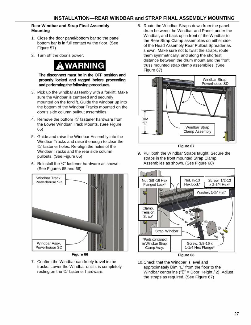
Rear Windbar and Strap Final Assembly
Mounting
1. Close the door panel/bottom bar so the panel
bottom bar is in full contact w/ the floor. (See
Figure 57)
2. Turn off the door’s power.
The disconnect must be in the OFF position and
properly locked and tagged before proceeding
and performing the following procedures.
3. Pick up the windbar assembly with a forklift. Make
sure the windbar is centered and securely
mounted on the forklift. Guide the windbar up into
the bottom of the Windbar Tracks mounted on the
door’s side column pullout assemblies.
4. Remove the bottom ¾” fastener hardware from
the Lower Windbar Track Mounts. (See Figure
65)
5. Guide and raise the Windbar Assembly into the
Windbar Tracks and raise it enough to clear the
¾” fastener holes. Re-align the holes of the
Windbar Tracks and the rear side column
pullouts. (See Figure 65)
6. Reinstall the ¾” fastener hardware as shown.
(See Figures 65 and 66)
Figure 66
7. Confirm the Windbar can freely travel in the
tracks. Lower the Windbar until it is completely
resting on the ¾” fastener hardware.
8. Route the Windbar Straps down from the panel
drum between the Windbar and Panel, under the
Windbar, and back up in front of the Windbar to
the Rear Strap Clamp assemblies on either side
of the Head Assembly Rear Pullout Spreader as
shown. Make sure not to twist the straps, route
them symmetrically, and along the shortest
distance between the drum mount and the front
truss mounted strap clamp assemblies. (See
Figure 67)
Figure 67
9. Pull both the Windbar Straps taught. Secure the
straps in the front mounted Strap Clamp
Assemblies as shown. (See Figure 68)
Figure 68
10. Check that the Windbar is level and
approximately Dim “E” from the floor to the
Windbar centerline (“E” = Door Height / 2). Adjust
the straps as required. (See Figure 67)
Screw, 1/2-13 x 2-3/4 Hex*
*Parts contained in Windbar Strap
Clamp Assy. #R1600873-0
Clamp, Tension Strap*
Nut, ½-13 Hex Lock*
Washer, ؽ” Flat*
Screw, 3/8-16 x 1-1/4 Hex Flange*
Nut, 3/8 -16 Hex Flanged Lock*
Strap, Windbar Ref. Part:
#R1600864-0 Windbar Assy,
Powerhouse SD Ref. Part:
1600849-0X00
Windbar Track, Powerhouse SD
Ref. Part: 1600856-0X00
Windbar Strap, Powerhouse SD
Ref. Part: 1600864-0
Windbar Strap Clamp Assembly
Ref. Part: #R1600873-0
DIM “E”

28
INSTALLATION—REAR WINDBAR HOOD ASSEMBLY (OPTIONAL)
11. After the Windbar is positioned correctly, tighten
all the fasteners.
IMPORTANT: Windbar Straps length must be
equal when fully installed. If this
is not done, Door and Windbar
performance will be affected and
may result in door operation
failure and/or damage.
12. Take the extra length of Windbar Strap and roll it
up in a tight roll. Zip tie the strap roll to the taught
strap by the clamp assembly. Do not cut off the
strap ends. Further adjustment may be
necessary in the future.
13. Re-energize the door’s power supply.
14. Jog the door to the full open position and check
that the windbar is above the door lintel and in
front of the bottom bar when the door is in the
fully open position. Also check that the windbar
moves smoothly and doesn’t hang up at all while
traveling in the tracks.
15. Jog the door down to the full closed position and
check that the windbar goes back to the doors
approximate center or DIM “E”. Again check that
the windbar moves smoothly and doesn’t hang up
at all while traveling in the tracks.
16. Repeat steps 14 and 15 several times or until
performance is consistent.
17. Remove the forklift from under the windbar.
18. Run the door through four or five complete cycles
to verify that the door and Windbar(s) are
operating smoothly and efficiently, and that
binding or unusual noises do not exist. Readjust
as necessary.
19. If adjustments are necessary place the forklift
under the windbar for support and adjust the
windbar and straps as required.
REAR WINDBAR HOOD ASSEMBLY (OPTIONAL)
The hood is an option for the Powerhouse SD door. It
is built at the factory and delivered separately to the
door site. The installer will have to assemble and
install the hood assembly. For installation of the Rear
Windbar Hood Assembly on a door refer to the “Hood
(Optional)” section along with the following additions.
The disconnect must be in the OFF position and
properly locked and tagged before proceeding
and performing the following procedures.
1. Fasten the Rear Windbar Hood Spreader to the
Windbar Pullout as shown (See Figure 69)
2. Prior to attaching both the right and left head
assembly end covers onto the front truss
assembly, install both End Cover Spacers. Align
the top of the spacers so they are flush w/ the
Rear Windbar Hood Spreader. Anchor the End
Cover Spacers to the wall. (See Figure 69)
Figure 69
3. Use ¹/₄-20 fasteners to secure the End Cover
Spacers to the End Covers. (See Figure 69)
Screw and Nut, ½-13 x 1.00” Hex
Hood to Wall Anchor Points
Windbar Pullout
¼-20 x ½” Hex Flanged Screws
and Nuts
End Cover
End Cover Spacer
29
ADJUSTMENTS—STRAPPED WINDBAR ADJUSTMENT (OPTIONAL FEATURE)
ADJUSTMENTS
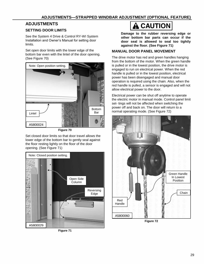
SETTING DOOR LIMITS
See the System 4 Drive & Control RY-WI System
Installation and Owner’s Manual for setting door
limits.
Set open door limits with the lower edge of the
bottom bar even with the lintel of the door opening.
(See Figure 70)
Figure 70
Set closed door limits so that door travel allows the
lower edge of the bottom bar to gently seal against
the floor resting lightly on the floor of the door
opening. (See Figure 71)
Figure 71
Damage to the rubber reversing edge or
other bottom bar parts can occur if the
door seal is allowed to seal too tightly
against the floor. (See Figure 71)
MANUAL DOOR PANEL MOVEMENT
The drive motor has red and green handles hanging
from the bottom of the motor. When the green handle
is pulled or in the lowest position, the drive motor is
engaged to run on electrical power. When the red
handle is pulled or in the lowest position, electrical
power has been disengaged and manual door
operation is required using the chain. Also, when the
red handle is pulled, a sensor is engaged and will not
allow electrical power to the door.
Electrical power can be shut off anytime to operate
the electric motor in manual mode. Control panel limit
set- tings will not be affected when switching the
power off and back on. The door will return to a
normal operating mode. (See Figure 72)
Figure 72
Lintel
Bottom Bar
Note: Open position setting.
Open Side Column
Reversing Edge
Note: Closed position setting.
A5800029
Red Handle
Chain
Green Handle In Lowest Position
A5800060
A5800024

30
ADJUSTMENTS—STRAPPED WINDBAR ADJUSTMENT (OPTIONAL)
STRAPPED WINDBAR ADJUSTMENT
(OPTIONAL)
1. Move the door panel to the open position.
2. Turn off the power to the door.
The disconnect must be in the OFF position and
properly locked and tagged before proceeding
and performing the following procedures.
3. The windbar(s) should be in the position shown in
Figure 73.
Figure 73
4. Inspect all strapped windbars (if installed). When
the door is opened, a strapped windbar should be
approximately at or just above the top of the door
opening. When both front and rear windbars are
installed, once the front windbar is properly
positioned, the rear windbar should be at the same
height. If the Windbars are too low they will be in
the open doorway and infringe traffic. (See Figure
73)
Keep tension on the windbar straps when
adjusting. The windbar is free to fall
when windbar straps are not retained by
the clamp plates and must be secured at
all times.
5. To adjust the rear windbar, pick up the windbar
assembly with a forklift. Make sure the windbar is
centered and securely supported on the forklift.
6. Loosen the rear strap clamp bolts and loosen the
straps up or down through the clamps as
necessary. Move the Windbar up or down, as
required, by raising or lowering the windbar on the
forklift. Also make sure the Windbar is level. (See
Figure 74)
7. Retighten the straps in the strap clamps after
properly leveling and adjusting the Windbar height.
8. Retighten the clamp bolts when the Windbar is in
the correct position and the straps retightened.
(See Figure 74)
Figure 74
9. To adjust the front windbar, pick up the windbar
assembly with a forklift. Make sure the windbar is
centered and securely supported on the forklift.
10. Loosen the front strap clamp bolts and loosen the
straps up or down through the clamps as
necessary. Move the Windbar up or down, as
required, by raising or lowering the windbar on the
forklift. Also make sure the Windbar is level. (See
Figure 75)
Bottom Bar
Door Lintel
Panel Drum
Windbar Strap
CORRECT SETTING
INCORRECT SETTING
Windbars are at or just above the Door Lintel as
shown
Panel Drum
Windbars are too high above the Door Lintel as
shown
Windbar Strap
Door Lintel
Screw, 1/2-13 x 2-3/4 Hex*
*Parts contained in Windbar Strap
Clamp Assy. #R1600873-0
Clamp, Tension Strap*
Nut, ½-13 Hex Lock*
Washer, ؽ” Flat*
Screw, 3/8-16 x 1-¼ Hex Flange*
Nut, 3/8 -16 Hex Flanged Lock*
Strap, Windbar Ref. Part:
#R1600864-0

31
ADJUSTMENTS—STRAPPED WINDBAR ADJUSTMENT (OPTIONAL FEATURE)
11. Retighten the straps in the strap clamps after
properly leveling and adjusting the Windbar
height.
12. Retighten the clamp bolts when the Windbar is in
the correct position and the straps retightened.
(See Figure 75)
Figure 75
13. Turn on the power to the door.
14. Run the door through four or five complete cycles
to verify that the door and Windbar(s) are
operating smoothly and efficiently, and that
binding or unusual noises do not exist. Readjust
as necessary.
Screw, 1/2-13 x 2-3/4 Hex*
*Parts contained in Assy. #R1600862-0
Clamp, Tension Strap*
Nut, ½-13 Hex Lock*
Washer, ؽ” Flat*
Screw, 3/8-16 x 1-1/4 Hex Flange*
Strap, Windbar Ref. Part:
#R1600864-0
Nut, 3/8 -16 Hex Flanged Lock*

32
MISCELLANEOUS—FINAL CHECKS
MISCELLANEOUS
FINAL CHECKS
NOTE: Check the following door systems and
components after the door panel has been
cycled at least 20 times.
Head Assembly: Check that all mounting hardware
is in place and properly tightened.
Side Columns: Check that the side columns are
plumb and square and that all anchor bolts are tightly
secured.
Light Curtain: Check that the light curtains operate
as described in the Powerhouse SD Owner’s
manual.
Activators: Check to see that the activators operate
as specified by the manufacturer.
Open and Close Limits: Check open and close
limits. See “SETTING DOOR LIMITS” on page 16.
Caulk: Ensure that all edges of the jamb and header
frames and pullouts are sealed where they meet the
wall of the building. Use a high-quality caulk rated for
the environment in which the door is installed, as
required.
Strapped Windbar: Positioned as described in both
the FRONT and REAR “WINDBAR and STRAP
FINAL ASSEMBLY MOUNTING” and “STRAPPED
WINDBAR ADJUSTMENT” sections (IF INSTALLED)
on pages 22, 27, and 30.

33
NOTES
