power with powe r with hydraulicsfile.yizimg.com/479421/2016810-91354490.pdfple tools through...
TRANSCRIPT
100 BAR
Power with hydraulics
www.rehobot.se
PRODUKTÖVERSIKT
240 mpAenstegshandpump, tvåstegshandpump, lufthydraulisk pump, bensinmotordri-ven pump, elmotordriven pump
58 HYDRAULISKA pUmpAR
100 BAR
poweR with hydRAulics
www.rehobot.se
PRODUCT OVERVIEW
hand pumps, electrical pumps, petrol driven pumps, air driven pumps, cylinders, holloW shaft cylinders, compact cylinders, accessories
industrial products
256 toN

2
Hydraulic pumps
ABout RehoBot hydRAulicsREHOBOT Hydraulics is a successful Swedish company. We develop, manufacture and market products & systems based on high-pressure hydraulics. Our high quality solutions are often used for Service & Maintenance purposes in harsh environments.
Our products are associated with a high quality and are well known. Mainly through the previous trademark of NIKE Hydraulics which REHOBOT acquired in 2010. The product range includes hydraulic pumps, cylinders, lift & garage equipment, tools and rescue equipment. Our business is divided into three main business areas:
• Industrial • Automotive • Rescue
REHOBOThasitsheadofficeinSweden,ScandinaviawhereallmanufacturingandR&Disdone.Throughoursalessubsidiaries located in United Kingdom, USA and China we achieve a presence covering the entire world. We are also represented in other parts of the world through a broad network of authorized dealers, distributors & service partners. We solve your problems
We have a solid experience developing and producing solutions based on high pressure hydraulics. New products are often the result of a design which usually become a part of a complete hydraulic solution. Always solving the requirements of our customers’ power problems! With the base in our 80 years of experience, we constantly develop cost effective solutions in terms of power, performance & functionality. We are stronger together
Our products are marketed and distributed in many parts of the world by an extensive dealer- and service network. You as a customer are also always welcome to contact REHOBOT directly or any of our subsideries. Together with our partners and customers we constantly create a mutual business success. No challenge is big enough and we look forward to work together with you.
3
Hydraulic pumps
AlwAys eXceediNG youR eXpectAtioNs!Quality has and always will be the base of REHOBOT’s success. Our goal is to always exceed your expectations! This hallmark partly arise by the quality of our products, but also thanks to our comprehensive customer service & support., short leadimes & delivery accuracy.
Our hydraulic solutions for Industrial, Rescue and Automotive applications consist of tools and components which can be found in many different industries and among users world-wide.
Process, mining, steel, construction and shipbuilding are just some of the many areas we serve. The product range includes hydraulic pumps, cylinders and a wide selection of acces-sories. Push-pull kits, puller for ball bearings & bushings, power tools such as spreaders and cutting tools, all constitute a part of our product offering.
Working in close collaboration and partnership with leading OEM’s REHOBOT develop customizedproducts&originalequipment.Wearealwyasopentolistentoyourspecificrequest and are often able to meet your demands.
We make sure our solutions alwats meet the customers unique needs and ensurie a long andmutuallyprofitablepartnership.
REHOBOTHydraulicsarecertifiedinaccordancewithISO9001&ISO14001-standards.
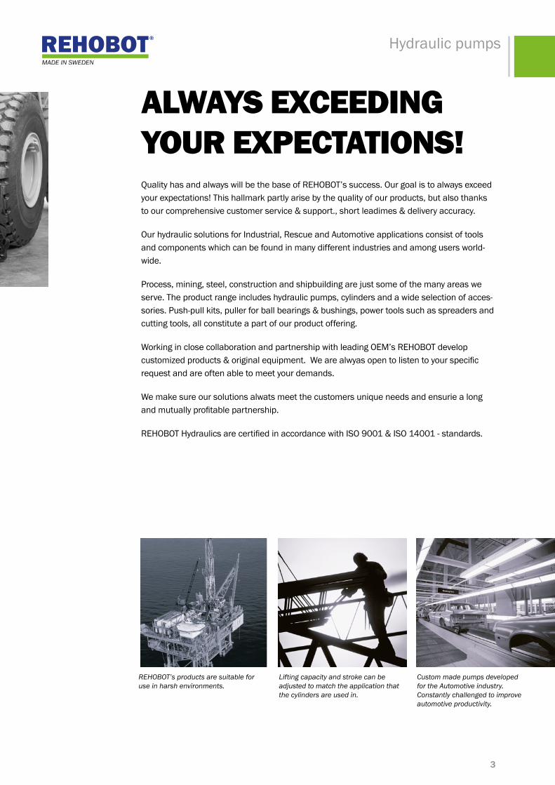
REHOBOT’s products are suitable for use in harsh environments.
Lifting capacity and stroke can be adjusted to match the application that the cylinders are used in.
Custom made pumps developed for the Automotive industry. Constantly challenged to improve automotive productivity.

4
REHOBOT pumps are used worldwide and every possi-ble environments. Some examples can be found within the engineering, automotive, mining and petrochemical industries.
We are happy to tailor the pumps to our customers' needs,thusprovidingflexibleandcosteffectivesolutions.
Ourdesignsarebasedonlongexperiencewithinthefieldof hydraulics. The results are pumps that are easy to repair & service - which saves time and money! The life of REHOBOT products is extremely long. Our pumps provide power that will last for generations!
hand driven pumps – are easy to move and requires no external power source. Hand pumps are economical, flexible,ergonomicallydesignedandareexcellentwheresubtle control is required.
pumps – cReAtiNG poweR!REHOBOT pumps have a functional design to withstand rough handling in harsh environments. The use can be found in many different applications & industries. The pumps can be used with all hydraulic tools and cylinders in the REHOBOT’s product range.
air driven pumps – an affordable option with faster and moreefficientoperationcomparedwithhandpumps.Requires access to compressed air.
electrically driven pumps– the best choice when a large capacity is needed, e.g. for operation of multiple cylin-ders. The pumps can easily be expanded to operate multi-ple tools through different valve systems. Requires access to an external electrical power source.
petrol driven pumps – a good alternative when a mobile pumping unit is required, for example on construction sites and shipyards. Requires no external power source. If hydraulic equipment already exists, the choice of the pump and accessories can be tailored to meet the re-quirement. We are happy to provide our knowledge and solutions!
RehoBot pumps hAs
•High performance • High quality • Functional design • Ergonomic & simple to operate
pump seRies
• PH - series - One stage hand pump • PHS - series - Two stage hand pump • PME - series - Electrical driven pumps • PMP - series - Petrol driven pumps • PP - series - Air driven pumps
5
Hydraulic pumps
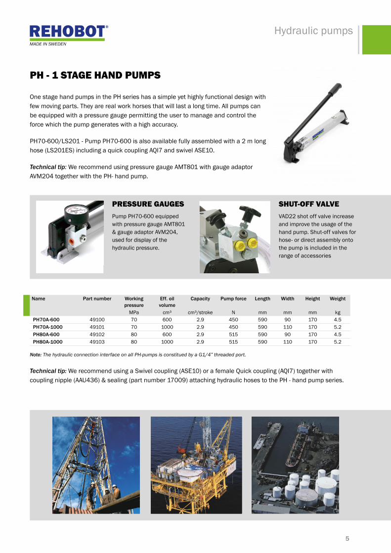
ph - 1 stAGe hANd pumps
One stage hand pumps in the PH series has a simple yet highly functional design with few moving parts. They are real work horses that will last a long time. All pumps can be equipped with a pressure gauge permitting the user to manage and control the force which the pump generates with a high accuracy.
PH70-600/LS201 - Pump PH70-600 is also available fully assembled with a 2 m long hose (LS201ES) including a quick coupling AQI7 and swivel ASE10.
Technical tip: We recommend using pressure gauge AMT801 with gauge adaptor AVM204togetherwiththePH-handpump.
name part number Working pressure
eff. oil volume
capacity pump force length Width height Weight
MPa cm³ cm³/stroke N mm mm mm kg ph70a-600 49100 70 600 2.9 450 590 90 170 4.5 ph70a-1000 49101 70 1000 2.9 450 590 110 170 5.2 ph80a-600 49102 80 600 2.9 515 590 90 170 4.5 ph80a-1000 49103 80 1000 2.9 515 590 110 170 5.2
pRessuRe GAuGesPump PH70-600 equipped with pressure gauge AMT801 &gaugeadaptorAVM204,used for display of the hydraulic pressure.
shut-oFF VAlVeVAD22 shot off valve increase and improve the usage of the hand pump. Shut-off valves for hose- or direct assembly onto the pump is included in the range of accessories
Note: The hydraulic connection interface on all PH-pumps is constitued by a G1/4” threaded port.
Technical tip: We recommend using a Swivel coupling (ASE10) or a female Quick coupling (AQI7) together with couplingnipple(AAU436)&sealing(partnumber17009)attachinghydraulichosestothePH-handpumpseries.
6
Hydraulic pumps
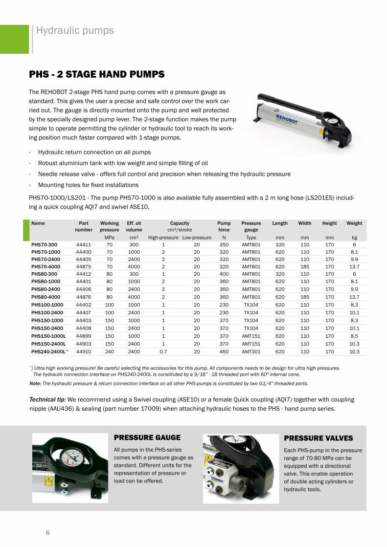
phs - 2 stAGe hANd pumpsThe REHOBOT 2-stage PHS hand pump comes with a pressure gauge as standard. This gives the user a precise and safe control over the work car-ried out. The gauge is directly mounted onto the pump and well protected by the specially designed pump lever. The 2-stage function makes the pump simple to operate permitting the cylinder or hydraulic tool to reach its work-ing position much faster compared with 1-stage pumps.
• Hydraulic return connection on all pumps
• Robustaluminiumtankwithlowweightandsimplefillingofoil
• Needle release valve - offers full control and precision when releasing the hydraulic pressure
• Mountingholesforfixedinstallations
PHS70-1000/LS201 - The pump PHS70-1000 is also available fully assembled with a 2 m long hose (LS201ES) includ-ing a quick coupling AQI7 and swivel ASE10.
name part number
Working pressure
eff. oil volume
capacity cm³/stroke
pump force
pressure gauge
length Width height Weight
MPa cm³ High-pressure Low-pressure N Type mm mm mm kgphs70-300 44411 70 300 1 20 350 AMT801 320 110 170 6phs70-1000 44400 70 1000 2 20 320 AMT801 620 110 170 8.1phs70-2400 44405 70 2400 2 20 320 AMT801 620 110 170 9.9phs70-4000 44875 70 4000 2 20 320 AMT801 620 185 170 13.7phs80-300 44412 80 300 1 20 400 AMT801 320 110 170 6phs80-1000 44401 80 1000 2 20 360 AMT801 620 110 170 8.1phs80-2400 44406 80 2400 2 20 360 AMT801 620 110 170 9.9phs80-4000 44876 80 4000 2 20 360 AMT801 620 185 170 13.7phs100-1000 44402 100 1000 1 20 230 TX104 620 110 170 8.3phs100-2400 44407 100 2400 1 20 230 TX104 620 110 170 10.1phs150-1000 44403 150 1000 1 20 370 TX104 620 110 170 8.3phs150-2400 44408 150 2400 1 20 370 TX104 620 110 170 10.1phs150-1000l 44899 150 1000 1 20 370 AMT151 620 110 170 8.5phs150-2400l 44903 150 2400 1 20 370 AMT151 620 110 170 10.3phs240-2400l*) 44910 240 2400 0.7 20 460 AMT301 620 110 170 10.3
pRessuRe GAuGeAll pumps in the PHS-series comes with a pressure gauge as standard. Different units for the representation of pressure or load can be offered.
pRessuRe VAlVesEach PHS-pump in the pressure range of 70-80 MPa can be equipped with a directional valve. This enable operation of double acting cylinders or hydraulic tools.
*) Ultra high working pressure! Be careful selecting the accessories for this pump. All components needs to be design for ultra high pressures. The hydraulic connection interface on PHS240-2400L is constituted by a 9/16” - 18 threaded port with 60º Internal cone.
Note: The hydraulic pressure & return connection interface on all other PHS-pumps is constituted by two G1/4” threaded ports.
Technical tip: We recommend using a Swivel coupling (ASE10) or a female Quick coupling (AQI7) together with coupling nipple(AAU436)&sealing(partnumber17009)whenattachinghydraulichosestothePHS-handpumpseries.

7
Hydraulic pumps
pme - electRicAlly dRiVeN pumpsREHOBOT’s electrically driven hydraulic pumps are reliable, versatile and easy to use. All pumps has a double-speed operation with automatic switching between high and low pressure at 2 MPa - 6 MPa depending on the pump type.
Thelow-pressureunitisagearpumpthatgivesahighflowuptotheswitchingpressure. The high-pressure unit is a single or double-piston pump. PME70-2030ADVandPME70-2030MRVareequippedwithfootactuatedpedalfor on/off control. All other models have a start/stop button placed on the mo-tor.
adv - Automatic release valve. Oil returns to tank when motor is switched off. The pressure built up in the tool then drops and the tool returns automatically. For crimping, cutting or press tools that are used in high-frequency applications. Not for lifting app- lications!
mrv - Manual release valve. Suitable when you want to maintain the pressure in the tool for an extended period and have a controlled release. Recommen- ded usage with tools for cable crimping or cutting.
ap - Adapter plate. This pump has no valve, but simply aconnectingplatewithG1/4”pressure&return ports.
mls - With lever valve for single-acting tool/cylinder.
mld - With lever valve for double-acting tool/cylinder.
ss - With solenoid valve for single-acting tool/ cylinder(24VDC).RemotecontrolTRC230- 24orexternalinputcontrolisneeded.
sd - With solenoid valve for double-acting tool/ cylinder(24VDC).RemotecontrolTRC230- 24orexternalinputcontrolisneeded.
name part number Working pressure
eff. oil volyme
capacity cm³/stroke
motor length Width height Weight
MPa cm³ Low pressure High pressure V/kW mm mm mm kg pme70-2030adv 43005 70 3200 2700 300 230/0.55 285 285 520 23 pme70-2030mrv 43006 70 3200 2700 300 230/0.55 335 285 520 23 pme70-2030ap 43000 70 3200 2700 300 230/0.55 285 285 520 23 pme70-2030mls 43001 70 3200 2700 300 230/0.55 330 285 520 24 pme70-2030mld 43002 70 3200 2700 300 230/0.55 330 285 520 24 pme70-2030ss 43003 70 3200 2700 300 230/0.55 380 300 520 27 pme70-2030sd 43004 70 3200 2700 300 230/0.55 380 300 520 27 pme70a-4100ap 43007 70 10000 7500 1600 400/2.2 335 370 575 45 pme70a-4100mls 43008 70 10000 7500 1600 400/2.2 375 370 575 46 pme70a-4100mld 43009 70 10000 7500 1600 400/2.2 375 370 575 46 pme70a-4100ss 43010 70 10000 7500 1600 400/2.2 430 370 575 49 pme70a-4100sd 43011 70 10000 7500 1600 400/2.2 430 370 575 49 pme70a-4200ap 43012 70 20000 7500 1600 400/2.2 460 525 525 62 pme70a-4200mls 43013 70 20000 7500 1600 400/2.2 480 525 525 63 pme70a-4200mld 43014 70 20000 7500 1600 400/2.2 480 525 525 63 pme70a-4200ss 43015 70 20000 7500 1600 400/2.2 460 525 525 66 pme70a-4200sd 43043 70 20000 7500 1600 400/2.2 460 525 525 66
Note: The hydraulic pressure & return connection interface on all PME-pumps are constituted by two G1/4” threaded ports.
Technical tip! The pumps can be equipped with a pressure gauge. We always recommend the use of REHOBOT originalparts:forinstancepressuregaugeAMT801andgaugeadapterAAM14forthePME-pumps.
Description of the valve alternatives:
8
Hydraulic pumps
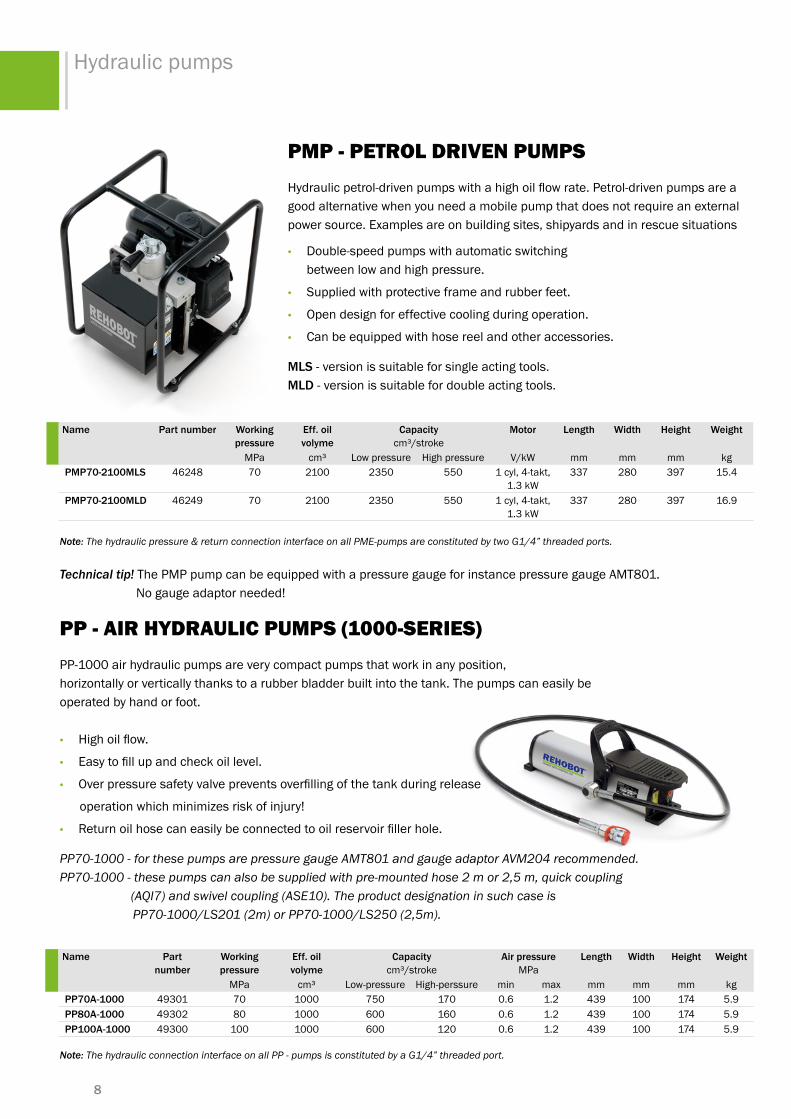
pmp - petRol dRiVeN pumpsHydraulicpetrol-drivenpumpswithahighoilflowrate.Petrol-drivenpumpsareagood alternative when you need a mobile pump that does not require an external power source. Examples are on building sites, shipyards and in rescue situations
• Double-speed pumps with automatic switching between low and high pressure.
• Supplied with protective frame and rubber feet.
• Open design for effective cooling during operation.
• Can be equipped with hose reel and other accessories.
mls - version is suitable for single acting tools. mld - version is suitable for double acting tools.
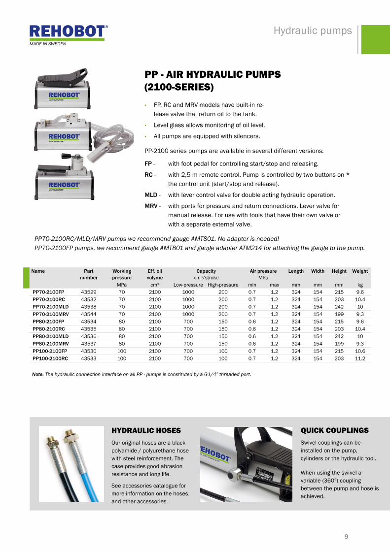
pp - AiR hydRAulic pumps (1000-seRies)PP-1000 air hydraulic pumps are very compact pumps that work in any position, horizontally or vertically thanks to a rubber bladder built into the tank. The pumps can easily beoperated by hand or foot.
• Highoilflow.
• Easytofillupandcheckoillevel.
• Overpressuresafetyvalvepreventsoverfillingofthetankduringrelease
operation which minimizes risk of injury!
• Returnoilhosecaneasilybeconnectedtooilreservoirfillerhole.
PP70-1000 - for these pumps are pressure gauge AMT801 and gauge adaptor AVM204 recommended. PP70-1000 - these pumps can also be supplied with pre-mounted hose 2 m or 2,5 m, quick coupling (AQI7) and swivel coupling (ASE10). The product designation in such case is PP70-1000/LS201 (2m) or PP70-1000/LS250 (2,5m).
name part number Working pressure
eff. oil volyme
capacity cm³/stroke
motor length Width height Weight
MPa cm³ Low pressure High pressure V/kW mm mm mm kg pmp70-2100mls 46248 70 2100 2350 550 1cyl,4-takt,
1.3kW337 280 397 15.4
pmp70-2100mld 46249 70 2100 2350 550 1cyl,4-takt,1.3kW
337 280 397 16.9
name part number
Working pressure
eff. oil volyme
capacity cm³/stroke
air pressure MPa
length Width height Weight
MPa cm³ Low-pressure High-perssure min max mm mm mm kg pp70a-1000 49301 70 1000 750 170 0.6 1.2 439 100 174 5.9 pp80a-1000 49302 80 1000 600 160 0.6 1.2 439 100 174 5.9 pp100a-1000 49300 100 1000 600 120 0.6 1.2 439 100 174 5.9
Note: The hydraulic pressure & return connection interface on all PME-pumps are constituted by two G1/4” threaded ports.
Technical tip! The PMP pump can be equipped with a pressure gauge for instance pressure gauge AMT801. No gauge adaptor needed!
Note: The hydraulic connection interface on all PP - pumps is constituted by a G1/4” threaded port.
9
Hydraulic pumps
hydRAulic hoses Our original hoses are a black polyamide / polyurethane hose with steel reinforcement. The case provides good abrasion resistance and long life.
See accessories catalogue for more information on the hoses. and other accessories.
QuicK coupliNGsSwivel couplings can be installed on the pump, cylinders or the hydraulic tool.
When using the swivel a variable(360º)couplingbetween the pump and hose is achieved.
PP70-2100RC/MLD/MRV pumps we recommend gauge AMT801. No adapter is needed! PP70-2100FP pumps, we recommend gauge AMT801 and gauge adapter ATM214 for attaching the gauge to the pump.
name part number
Working pressure
eff. oil volyme
capacity cm³/stroke
air pressure MPa
length Width height Weight
MPa cm³ Low-pressure High-pressure min max mm mm mm kg pp70-2100fp 43529 70 2100 1000 200 0.7 1.2 324 154 215 9.6 pp70-2100rc 43532 70 2100 1000 200 0.7 1.2 324 154 203 10.4 pp70-2100mld 43538 70 2100 1000 200 0.7 1.2 324 154 242 10 pp70-2100mrv 43544 70 2100 1000 200 0.7 1.2 324 154 199 9.3 pp80-2100fp 43534 80 2100 700 150 0.6 1.2 324 154 215 9.6 pp80-2100rc 43535 80 2100 700 150 0.6 1.2 324 154 203 10.4 pp80-2100mld 43536 80 2100 700 150 0.6 1.2 324 154 242 10 pp80-2100mrv 43537 80 2100 700 150 0.6 1.2 324 154 199 9.3 pp100-2100fp 43530 100 2100 700 100 0.7 1.2 324 154 215 10.6 pp100-2100rc 43533 100 2100 700 100 0.7 1.2 324 154 203 11.2
pp - AiR hydRAulic pumps (2100-seRies)• FP, RC and MRV models have built-in re-
lease valve that return oil to the tank.
• Level glass allows monitoring of oil level.
• All pumps are equipped with silencers.
PP-2100 series pumps are available in several different versions:
fp - with foot pedal for controlling start/stop and releasing.
rc- with2,5mremotecontrol.Pumpiscontrolledbytwobuttonson* the control unit (start/stop and release).
mld - with lever control valve for double acting hydraulic operation.
mrv - with ports for pressure and return connections. Lever valve for manual release. For use with tools that have their own valve or with a separate external valve.
Note: The hydraulic connection interface on all PP - pumps is constituted by a G1/4” threaded port.

10
Hydraulic pumps
pp - AiR hydRAulic pumps (9000-seRies)PP-9000seriespumpsaredeliveredwithremotecontrol.Pumpiscontrolledby two buttons on the control unit (start/stop and release).
RC Pump with remote control. The pump is controlled by control buttons (start / stop loading and unloading).
• Largetankcapacity(9liter).
• Separate pressure gauge connection.
• Can easily be equipped with manifold blocks and valves for e.g. controlling more than one cylinder.
name part number Working pressure
eff. oil volyme
capacity cm³/stroke
air pressure MPa
length Width height Weight
MPa cm³ Low-pressure High-pressure min max mm mm mm kg pp70-9000rc 46545 70 9000 1000 200 0.65 1.2 340 247 311 18.4 pp80-9000rc 46549 80 9000 700 150 0.6 1.2 340 247 311 18
Note: The hydraulic pressure connection interface on all PP-pumps is constituted by a G1/4” threaded port.
Technical tip! For these pumps we recommend gauge AMT801. No adapter is needed
11
Hydraulic pumps
poweR with hydRAulics
www.rehobot.se
PRODUCT OVERVIEWhydraulic cylinders
256 toNpush cylinders, pull cylinders, holloW shaft cylinders, loW Weight cylinders, stainless cylinders, compact cylinders

12
REHOBOT's cylinders are used worldwide and in all possible environments. Some examples can be found within the engineering, automotive, mining and petrochemical industries.
The standard range of products is rich with cylinders of different strokes and capacity. We also provide a wide range of accessories extending the use of the cylinders.
We are happy to tailor the cylinders to our customers' needs.Somethingthatenablesflexibleandcosteffectivesolutions with virtually unlimited lifting capacity. The cylinders are an effective tool for all use ranging from smallprecisionworktoliftingof500-tonbridgesections.
Our designs are based on a very long experience within thefieldofhydraulics.Theresultsarecylinderswhichare easy to repair and service - saving time and money.
cyliNdeRs – hiGh poweR At A limited spAce!REHOBOT’S cylinders are designed to withstand rough handling in harsh environments. Their use are highly varied. The cylinders can be used wherever there is something which needs to be pulled, pushed or lifted.
providing a low total cost of ownership for the user. The pistons on our cylinders are hard chromed, making them resistant to wear and free of rust. The life of REHOBOT's products is extremely long. - Our cylinders simply last for generations!
The choice of the cylinder is normally selected by the working operation, pressure range, stroke and boundary dimensions of the cylinder. Considerations when selecting thecylinderforaspecificapplicationshouldalsobegivento the available range various accessories like extension tubes, pressure heads etc. All to make the most out of the hydraulic solution.
When an existing hydraulic equipment is available, the selection of cylinder preferably become based on the existing equipment's pressure range. All to generatethe greatestflexibilityandoveralleconomy.
RehoBot - cyliNdeRs hAs
• Hard chromed pistons, making them resistant to wear and free of rust.
• Galvanised cylinders for increaed corrosion resistance.
• Mechnical stop for the piston movement
QuicK coupliNG oN cyliNdeRs
• AQU8 quick coupling is normally mounted on all cylinders.
• AQI24quickcoupling(female)canbeequippedduring manufacturing. In such cases shall a ’’P’’ be added toptheproductdesignation,e.g.CF104P.

13
Hydraulic cylinders
cF/cFu - siNGle ActiNG push cyliNdeR with spRiNG RetuRN
CF cylinders are workhorses in REHOBOT’s cylinder range. They can be used for a va-riety of purposes. They are included in our push and pull kits (for details see separate data sheet). The cylinders are designed for attachment of accessories in the piston pin or cylinder base.
CFcylindersareavailablewithcapacityupto5tons,10tonsor25tonsandstrokelengthsbetween127mm-300mm.WealsoprovideCFcylinderswithextralongpiston rods, the so called CFU - series.
name part pressure capacity stroke stroke volume piston rod piston area diameter height Weightnumber MPa kN (t) mm cm³ ø mm cm² mm mm kg
cf104 27485 70 49(5) 127 90 26.5 7.1 37.5 266 1.7cf204 27486 70 49(5) 200 142 26.5 7.1 37.5 339 2.4cf110 43829 70 111 (11) 150 239 38 15.9 56.5 321 4.7cf210 43830 70 111 (11) 200 318 38 15.9 56.5 372 5.5cf310 43831 70 111 (11) 300 477 38 15.9 56.5 474 7cf120 24178 70 232(24) 127 422 60 33.2 84 337 10.2cf220 24973 70 232(24) 200 664 60 33.2 84 410 12.4cf320 24974 70 232(24) 300 996 60 33.2 84 510 16cfu2010 43837 70 111 (11) 200 318 38 15.9 56.5 387 5.3cfu2510 43838 70 111 (11) 250 398 38 15.9 56.5 437 6
cFA - AlumiNium push cyliNdeRs with spRiNG RetuRN
REHOBOTpushcylindersintheCFAserieshasacapacitybetween23&50tonnesand are made of aluminium. Aluminium provide superior performance in the rela-tionshipbetweencapacityandweight(about50%morepowerperkilocomparedwith similar cylinders made of steel). The cylinders are made out of high strength aluminium which gives it a much longer life compared with similar products on the market. The cylinder and piston are anodised for increased wear and corrosion protection.
CFA cylinders come as default with a top lip and a protective bottom plate of steel. All to warrant functionality even when the base and lifting point is rough.
NOTE! Aluminium cylinders in REHOBOT product range are designed for use with low cycles which is normal during service & maintenance. These aluminium cylinders has been designed to provide a lifetime of at least 10,000 cycles at full pressure. The cylinders should not be used in applications with high cycle number. For such use, please contact your REHOBOT dealer for advice.
name part pressure capacity stroke stroke volume piston piston area diameter height Weightnumber MPa kN (t) mm cm³ ø mm cm² mm mm kg
cfa250-100 48978 70 230(23) 100 332 60 33.2 100 212 4.4 cfa250-200 48980 70 230(23) 200 664 60 33.2 100 312 5.9 cfa500-100 47153 70 500(51) 100 709 85 70.9 140 224 9.2 cfa500-200 47160 70 500(51) 200 1418 85 70.9 140 324 12.7 cfa750-100 47187 70 730(74) 100 1039 100 103.9 170 235.5 14 cfa750-200 47188 70 730(74) 200 2078 100 103.9 170 335.5 18.3 cfa1000-100 47163 70 930(95) 100 1327 110 132.7 190 243 18.4 cfa1000-200 47171 70 930(95) 200 2655 110 132.7 190 343 24.7

14
Hydraulic cylinders
cFc - compAct siNGle ActiNG, push cyliNdeRs with spRiNG RetuRN
CFC cylinders are real all-round cylinders. We offer are a large number of variants of CFC cylin-ders with different properties such as capacity, stroke length and height. Everything to meet your requirements! The design allows small dimensions and built in measurements. The cylinders are fittedwithscraperstokeepthepistoncleanfromdirt,alwaysensuringproperfunctioninharshenvironments.
• Wiper polyurethane, positioned so that dirt can not pen-etrate between the piston rod and cylinder
• Corrosion protection - plated piston rod and electroplated cylinder
•Can be equipped with REHOBOT accessories
CFCcylindersareavailableincapacitiesbetween5to100tons.Modelswith5t,10t,15tand25tonscapacitycanbefittedwithadaptersformountingofaccessoriessuchaspressureheads and chains extending the use of the cylinder
name part pressure capacity stroke stroke volume piston piston area diameter height Weightnumber MPa kN (t) mm cm³ ø mm cm² mm mm kg
cfc51 40184 70 49(5) 27 19 25 7 38 110 0.8cfc53 40186 70 49(5) 77 55 25 7 38 165 1.2cfc55 40188 70 49(5) 127 90 25 7 38 216 1.5cfc57 40190 70 49(5) 181 128 25 7 38 273 1.9cfc59 40192 70 49(5) 232 165 25 7 38 324 2.2cfc101 40235 70 111 (11) 25 40 38 16 57 90 1.5cfc102 40237 70 111 (11) 54 86 38 16 57 121 2cfc104 40239 70 111 (11) 105 167 38 16 57 171 2.7cfc106 39849 70 111 (11) 155 247 38 16 57 247 4cfc108 39850 70 111 (11) 206 328 38 16 57 298 4.6cfc1010 39851 70 111 (11) 257 409 38 16 57 349 5.3cfc1012 39852 70 111 (11) 305 485 38 16 57 400 6cfc1014 39853 70 111 (11) 356 566 38 16 57 451 6.8cfc151 40264 70 166 (17) 25 59 48 24 70 124 3cfc152 40266 70 166 (17) 51 121 48 24 70 149 3.5cfc154 40268 70 166 (17) 101 240 48 24 70 200 4.5cfc156 39881 70 166 (17) 152 361 48 24 70 272 6.5cfc158 39882 70 166 (17) 203 482 48 24 70 322 7.5cfc1510 39883 70 166 (17) 254 603 48 24 70 373 8.5cfc1512 39884 70 166 (17) 305 725 48 24 70 424 9.5cfc1514 39885 70 166 (17) 356 846 48 24 70 475 10.9cfc251 39940 70 232(24) 25 83 60 33 85 140 5.1cfc252 39941 70 232(24) 51 169 60 33 85 165 5.9cfc254 39942 70 232(24) 101 335 60 33 85 216 7.7cfc256 39943 70 232(24) 159 528 60 33 85 273 9.7cfc258 39944 70 232(24) 209 694 60 33 85 324 11.5cfc2510 39945 70 232(24) 260 863 60 33 85 375 13.3cfc2512 39946 70 232(24) 311 1032 60 33 85 426 15cfc2514 39947 70 232(24) 362 1201 60 33 85 476 17cfc502 40292 70 496(51) 53 376 80 71 127 176 16cfc504 40294 70 496(51) 104 737 80 71 127 227 19cfc506 40296 70 496(51) 159 1127 80 71 127 282 23cfc5013 40298 70 496(51) 337 2389 80 71 127 460 35cfc756 40344 70 727(74) 155 1610 100 104 146 282 30cfc7513 40345 70 727(74) 333 3459 100 104 146 492 48cfc1006 40388 70 929(95) 168 2230 100 133 175 359 54cfc10010 40389 70 929(95) 260 3451 100 133 175 450 65

15
Hydraulic cylinders
cl - low push cyliNdeRs without spRiNG RetuRN• Compact measurements and space limited design
• Prepared with mounting holes for fastening
• Exchangeable reinforced pressure head
CL-cylinders are ideal for those who need a compact installation dimensions. Holes in cylinder bottom makes them easy to integrate into the application.
clF - low push cyliNdeRs with spRiNG RetuRN
CLFcylindersaretherightchoiceforthosewhoneedflexiblecylinderswithsmalldimensions.Withcapacitiesrangingfrom5tonsto200tons makes them suitable for lifting and other for purposes. Threaded mounting holes make them easy to integrate into various applications.
TheCLFseriesisalsoREHOBOT’ssmallestcylinder-CLF50-10reachanheightofonly37mm,butwithanincredible5-tonliftingcapacity.CylindersCLF670-45andCLF1100-40areequippedwitharemovablehandle to facilitate their handling.
name part pressure capacity stroke stroke volume piston piston area diameter height Weightnumber MPa kN (t) mm cm³ ø mm cm² mm mm kg
clf50-10 35132 70 50(5) 10 7.1 24 7.1 60 37 0.6clf110-10 35133 70 111 (11) 10 15.9 35 15.9 80 43 1.5clf110-30 47067 70 111 (11) 28 44.5 35 15.9 65 75 1.8clf220-13 35320 70 218 (22) 13.5 42.1 50 31.2 100 50 2.6clf220-50 37553 70 218 (22) 50 156 50 31.2 85 107 3.9clf450-15 35305 70 445(45) 15 95.4 60 63.6 134 68 6.4clf450-40 47071 70 445(45) 40 254.4 60 63.6 120 120 8.8clf670-15 35413 70 665(68) 15 142.5 80 95 146 78 9.2clf670-45 47075 70 665(68) 45 427.5 80 95 146 130 14.3clf1100-15 35166 70 1078 (110) 15 231 100 154 180 90 17clf1100-40 47079 70 1078 (110) 40 616 100 154 180 140 23.7clf1500-15 35485 70 1498(153) 15 321 125 214 220 100 28clf2000-16 35490 70 1985(202) 16 454 140 284 250 110 40
name part pressure capavity stroke stroke volume piston piston area diameter height Weightnumber MPa kN (t) mm cm³ ø mm cm² mm mm kg
cl50-25 35680 70 49(5) 25 18 26 7.1 39 60 0.7
hydRAulic hosesOur original hoses are a black polyamide / polyurethane hose with steel reinforcement. The case provides good abrasion resistance and long life.
See accessories catalogue for more information on the hoses and other accessories.
QuicK coupliNGsSwivel couplings can be installed on either pump, cylinders or on the hydraulic tools.
When using the swivel a variable(360º)couplingbetween the pump and hose is achieved.

16
Hydraulic cylinders
name part number
pressure capacity kn (t)
capacity kn (t)
stroke stroke vol. piston piston area
diameter height Weight
MPa at 70MPa at 80MPa mm cm³ ø mm cm² mm mm kg csf110-50 45092 80 111 (11) 127(13) 50 80 45 15,9 58 134 2,3 csf110-100 45094 80 111 (11) 127(13) 100 159 45 15,9 58 184 3,0 csf110-150 45096 80 111 (11) 127(13) 150 238 45 15,9 58 234 3,7 csf220-25 45098 80 218 (22) 249(25) 25 78 63 31,2 80 115 3,7 csf220-50 45100 80 218 (22) 249(25) 50 156 63 31,2 80 140 4,4 csf220-100 45102 80 218 (22) 249(25) 100 312 63 31,2 80 190 5,9 csf220-150 45104 80 218 (22) 249(25) 150 467 63 31,2 80 240 7,3 csf220-200 45106 80 218 (22) 249(25) 200 623 63 31,2 80 290 8,7 csf350-50 45108 80 352(36) 402(41) 50 241 80 50,2 105 146 8,5 csf350-100 45110 80 352(36) 402(41) 100 502 80 50,2 105 196 11,0 csf350-200 45112 80 352(36) 402(41) 200 1005 80 50,2 105 296 15,6 csf550-50 45114 80 550(56) 628(64) 50 393 100 78,5 130 160 14,0 csf550-100 45116 80 550(56) 628(64) 100 785 100 78,5 130 210 17,7 csf550-200 45118 80 550(56) 628(64) 200 1570 100 78,5 130 310 24,9 csf860-50 45120 80 859(88) 982(100) 50 613 125 122,6 160 183 23,7 csf860-100 45122 80 859(88) 982(100) 100 1227 125 122,6 160 233 28,9 csf860-200 45124 80 859(88) 982(100) 200 2453 125 122,6 160 333 39,3
cX - siNGle ActiNG push cyliNdeRs FoR hiGh loAds
CX-seriescylindersreachupto250tonliftingcapacity.Theyarespeciallydesignedtocope with oblique loads. The CX-cylinder is also equipped with special piston guid-ance, a patented cylinder design which eliminate the risk of damage to the piston during movement.
CX250-100mayuponrequestbemanufacturedindouble-actiondesignsandwithother strokes. Please contact your REHOBOT dealer or us directly.
CX series are approved for pressures up to 80 MPa (800 bar).
name part pressure capacity stroke stroke vol. piston piston area diameter height Weightnummer MPa kN (t) mm cm³ ø mm cm² mm mm kg
cX250-100 49460 80 2513(256) 100 3140 180 314 250 285 79
csF - stAiNless siNGle ActiNG push cyliNdeRs with spRiNG RetuRN• CSF-cylindersareavailablewith11ton(13*)to88(100*)
tonscapacityandwith50to200mmstrokelength.
• Designed to compensate oblique loads better than conventional cylinders.
• Manufactured in stainless steel with hard chromatid piston.
All CSF - cylinders are equipped with spring return, stripping and quick coupling. ModelCSF350hasalsoacarryinghandlemountedonthecylinderframe.*CSF-series are approved for working pressures up to 80 MPa (800 bar).
17
Hydraulic cylinders
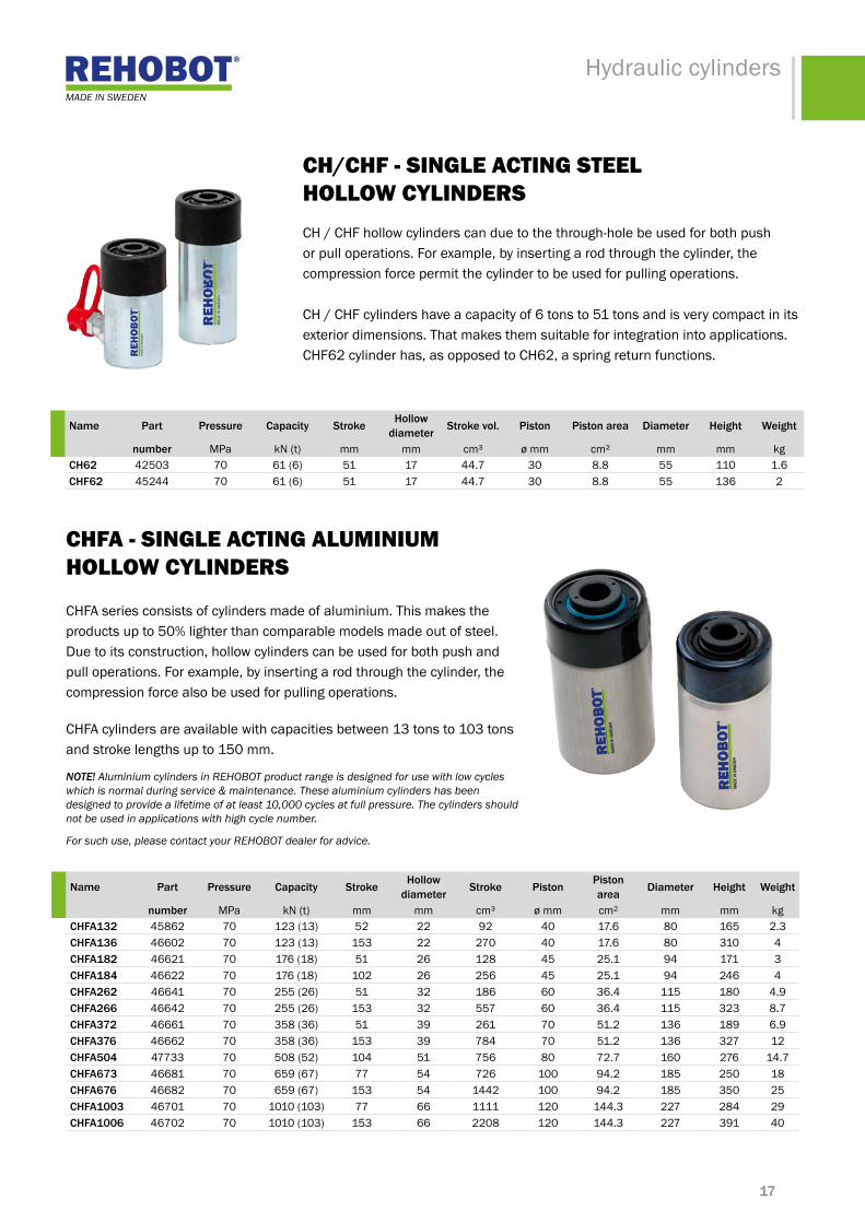
chFA - siNGle ActiNG AlumiNium hollow cyliNdeRs
CHFA series consists of cylinders made of aluminium. This makes the productsupto50%lighterthancomparablemodelsmadeoutofsteel.Due to its construction, hollow cylinders can be used for both push and pull operations. For example, by inserting a rod through the cylinder, the compression force also be used for pulling operations.
CHFAcylindersareavailablewithcapacitiesbetween13tonsto103tonsandstrokelengthsupto150mm.
NOTE! Aluminium cylinders in REHOBOT product range is designed for use with low cycles which is normal during service & maintenance. These aluminium cylinders has been designed to provide a lifetime of at least 10,000 cycles at full pressure. The cylinders should not be used in applications with high cycle number.
For such use, please contact your REHOBOT dealer for advice.
name part pressure capacity stroke hollow diameter stroke piston piston
area diameter height Weight
number MPa kN (t) mm mm cm³ ø mm cm² mm mm kgchfa132 45862 70 123(13) 52 22 92 40 17.6 80 165 2.3chfa136 46602 70 123(13) 153 22 270 40 17.6 80 310 4chfa182 46621 70 176 (18) 51 26 128 45 25.1 94 171 3chfa184 46622 70 176 (18) 102 26 256 45 25.1 94 246 4chfa262 46641 70 255(26) 51 32 186 60 36.4 115 180 4.9chfa266 46642 70 255(26) 153 32 557 60 36.4 115 323 8.7chfa372 46661 70 358(36) 51 39 261 70 51.2 136 189 6.9chfa376 46662 70 358(36) 153 39 784 70 51.2 136 327 12chfa504 47733 70 508(52) 104 51 756 80 72.7 160 276 14.7chfa673 46681 70 659(67) 77 54 726 100 94.2 185 250 18chfa676 46682 70 659(67) 153 54 1442 100 94.2 185 350 25chfa1003 46701 70 1010(103) 77 66 1111 120 144.3 227 284 29chfa1006 46702 70 1010(103) 153 66 2208 120 144.3 227 391 40
ch/chF - siNGle ActiNG steel hollow cyliNdeRs CH / CHF hollow cylinders can due to the through-hole be used for both push or pull operations. For example, by inserting a rod through the cylinder, the compression force permit the cylinder to be used for pulling operations.
CH/CHFcylindershaveacapacityof6tonsto51tonsandisverycompactinitsexterior dimensions. That makes them suitable for integration into applications. CHF62 cylinder has, as opposed to CH62, a spring return functions.
name part pressure capacity stroke hollow diameter stroke vol. piston piston area diameter height Weight
number MPa kN (t) mm mm cm³ ø mm cm² mm mm kgch62 42503 70 61 (6) 51 17 44.7 30 8.8 55 110 1.6chf62 45244 70 61 (6) 51 17 44.7 30 8.8 55 136 2
18
Hydraulic cylinders
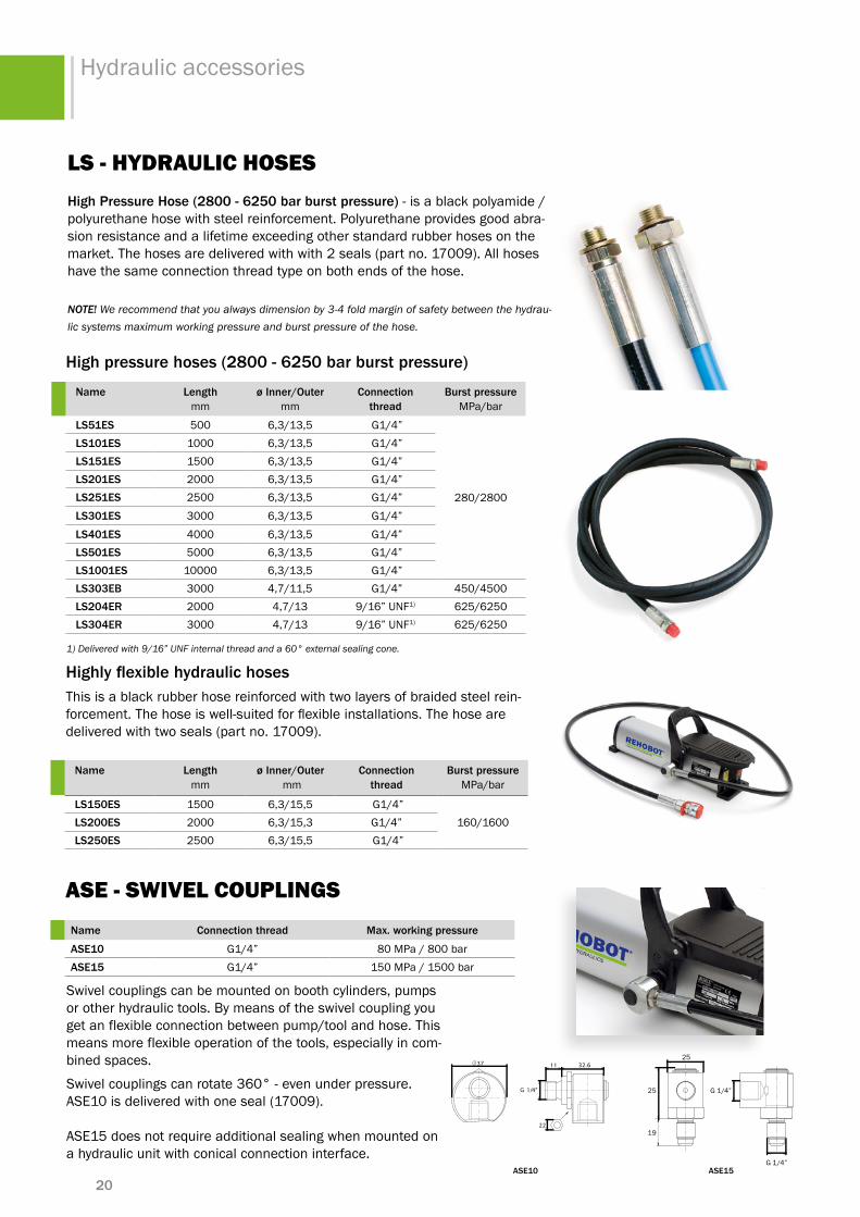
cpF - pull cyliNdeRs
CPFcylindersarepullingcylindersof5tonsor11tonscapacity.Theyare part of REHOBOT push and pull kits having threads on the piston top and cylinder bottom for attachment of accessories.
CPF cylinders are used, for example when reshaping welded structures.
name part pressure capacity stroke stroke volume piston piston area diameter height Weightnumber MPa kN (t) mm cm³ ø mm cm² mm mm kg
cpf705 27300 70 45(5) 125 80 20 6 48 412 2.4cpf709 27280 70 110 (11) 127 199 32 16 70 436 5.9
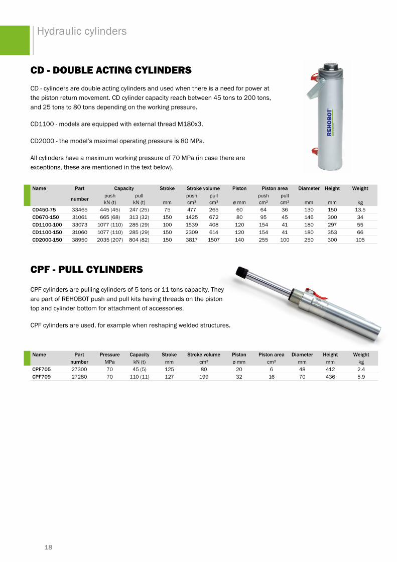
cd - douBle ActiNG cyliNdeRsCD - cylinders are double acting cylinders and used when there is a need for power at thepistonreturnmovement.CDcylindercapacityreachbetween45tonsto200tons,and25tonsto80tonsdependingontheworkingpressure.
CD1100-modelsareequippedwithexternalthreadM180x3.
CD2000 - the model’s maximal operating pressure is 80 MPa.
All cylinders have a maximum working pressure of 70 MPa (in case there are exceptions, these are mentioned in the text below).
name part capacity stroke stroke volume piston piston area diameter height Weight
number pushkN (t)
pull kN (t) mm
push cm³
pull cm³ ø mm
push cm²
pull cm² mm mm kg
cd450-75 33465 445(45) 247(25) 75 477 265 60 64 36 130 150 13.5cd670-150 31061 665(68) 313(32) 150 1425 672 80 95 45 146 300 34cd1100-100 33073 1077 (110) 285(29) 100 1539 408 120 154 41 180 297 55cd1100-150 31060 1077 (110) 285(29) 150 2309 614 120 154 41 180 353 66cd2000-150 38950 2035(207) 804(82) 150 3817 1507 140 255 100 250 300 105

19
Hydraulic cylinders
poweR with hydRAulics
www.rehobot.se
PRODUCT OVERVIEW hydraulic accessories
FleXiBlechains, hydraulic oil, eXtension tubes, Quick coup-lings, valves, pressure heads, manifold blocks, hydraulic hoses, cylinder adptors
20
Hydraulic accessories
high pressure hoses (2800 - 6250 bar burst pressure)
name lengthmm
ø inner/outermm
connection thread
burst pressureMPa/bar
ls51es 500 6,3/13,5 G1/4”
280/2800
ls101es 1000 6,3/13,5 G1/4”ls151es 1500 6,3/13,5 G1/4”ls201es 2000 6,3/13,5 G1/4”ls251es 2500 6,3/13,5 G1/4”ls301es 3000 6,3/13,5 G1/4”ls401es 4000 6,3/13,5 G1/4”ls501es 5000 6,3/13,5 G1/4”ls1001es 10000 6,3/13,5 G1/4”ls303eb 3000 4,7/11,5 G1/4” 450/4500ls204er 2000 4,7/13 9/16”UNF1) 625/6250ls304er 3000 4,7/13 9/16”UNF1) 625/6250
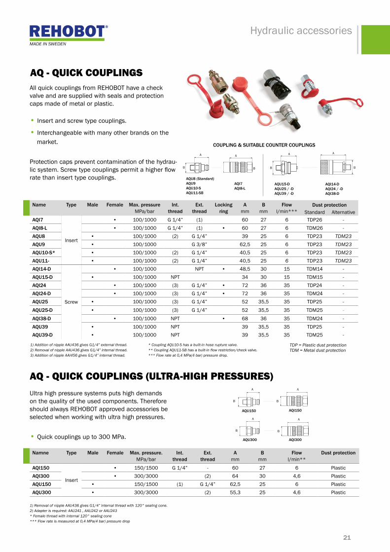
Highly flexible hydraulic hosesThis is a black rubber hose reinforced with two layers of braided steel rein-forcement.Thehoseiswell-suitedforflexibleinstallations.Thehosearedeliveredwithtwoseals(partno.17009).
name length mm
ø inner/outer mm
connection thread
burst pressureMPa/bar
ls150es 1500 6,3/15,5 G1/4”160/1600ls200es 2000 6,3/15,3 G1/4”
ls250es 2500 6,3/15,5 G1/4”
high pressure hose (2800 - 6250 bar burst pressure) - is a black polyamide / polyurethane hose with steel reinforcement. Polyurethane provides good abra-sion resistance and a lifetime exceeding other standard rubber hoses on the market.Thehosesaredeliveredwithwith2seals(partno.17009).Allhoseshave the same connection thread type on both ends of the hose.
NOTE! We recommend that you always dimension by 3-4 fold margin of safety between the hydrau-lic systems maximum working pressure and burst pressure of the hose.
ls - hydRAulic hoses
Swivel couplings can be mounted on booth cylinders, pumps or other hydraulic tools. By means of the swivel coupling you get an flexible connection between pump/tool and hose. This means more flexible operation of the tools, especially in com-bined spaces.
Swivelcouplingscanrotate360°-evenunderpressure. ASE10isdeliveredwithoneseal(17009). ASE15doesnotrequireadditionalsealingwhenmountedona hydraulic unit with conical connection interface.
Ase - swiVel coupliNGsname connection thread Max. working pressure
ase10 G1/4” 80 MPa / 800 barase15 G1/4” 150MPa/1500bar
1) Delivered with 9/16” UNF internal thread and a 60° external sealing cone.
37 32.611
G 1/4"
22
G1/4”
19
25
G1/4”
25
ase10 ase15
21
Hydraulic accessories
B
A
B
A
B
A
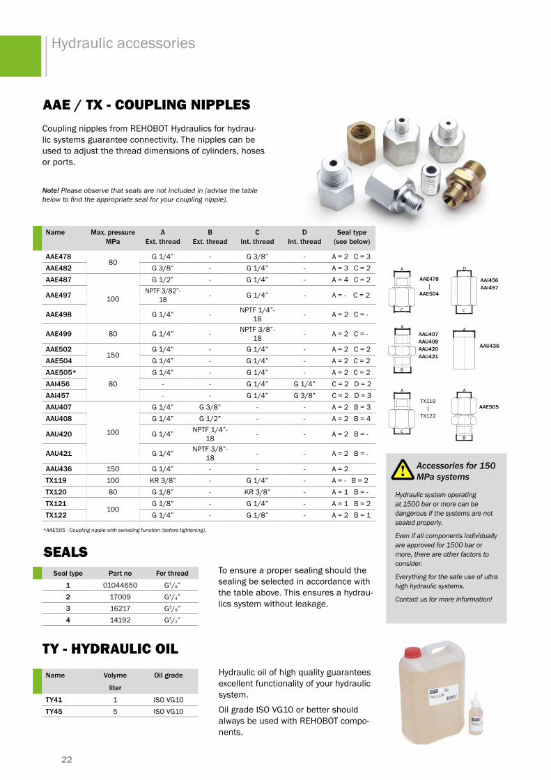
AQ - QuicK coupliNGsAll quick couplings from REHOBOT have a check valve and are supplied with seals and protection caps made of metal or plastic. • Insert and screw type couplings.
• Interchangeable with many other brands on the market.
Protection caps prevent contamination of the hydrau-licsystem.Screwtypecouplingspermitahigherflowrate than insert type couplings.
name type male female Max. pressureMPa/bar
int.thread
Ext.thread
locking ring
amm
bmm
flowl/min***
dust protectionStandard Alternative
aQi7
Insert
• 100/1000 G1/4” (1) 60 27 6 TDP26 -aQi8-l • 100/1000 G1/4” (1) • 60 27 6 TDM26 -aQu8 • 100/1000 (2) G1/4” 39 25 6 TDP23 TDM23aQu9 • 100/1000 G3/8” 62,5 25 6 TDP23 TDM23aQu10-s* • 100/1000 (2) G1/4” 40,5 25 6 TDP23 TDM23aQu11- • 100/1000 (2) G1/4” 40,5 25 6 TDP23 TDM23aQi14-d
Screw
• 100/1000 NPT • 48,5 30 15 TDM14 -aQu15-d • 100/1000 NPT 34 30 15 TDM15 -aQi24 • 100/1000 (3) G1/4” • 72 36 35 TDP24 -aQi24-d • 100/1000 (3) G1/4” • 72 36 35 TDM24 -aQu25 • 100/1000 (3) G1/4” 52 35,5 35 TDP25 -
aQu25-d • 100/1000 (3) G1/4” 52 35,5 35 TDM25 -
aQi38-d • 100/1000 NPT • 68 36 35 TDM24 -aQu39 • 100/1000 NPT 39 35,5 35 TDP25 -aQu39-d • 100/1000 NPT 39 35,5 35 TDM25 -
namne type male female Max. pressure.MPa/bar
int.thread
Ext.thread
amm
bmm
flowl/min**
dust protection
aQi150
Insert
• 150/1500 G1/4” - 60 27 6 PlasticaQi300 • 300/3000 (2) 64 30 4,6 PlasticaQu150 • 150/1500 (1) G1/4” 62,5 25 6 PlasticaQu300 • 300/3000 (2) 55,3 25 4,6 Plastic
AQ - QuicK coupliNGs (ultRA-hiGh pRessuRes)Ultra high pressure systems puts high demands on the quality of the used components. Therefore should always REHOBOT approved accessories be selected when working with ultra high pressures.
• Quick couplings up to 300MPa.
B
A
B
A
aQi14-daQi24 / -daQi38-d
aQu15-d aQu25 / -d aQu39 / -d
B
A
B
A
aQu8 (Standard) aQu9 aQu10-saQu11-sb
aQi7aQi8-l
1) Addition of nipple AAU436 gives G1/4” external thread. * Coupling AQU10-S has a built-in hose rupture valve.2) Removal of nipple AAU436 gives G1/4” internal thread. ** Coupling AQU11-SB has a built-in flow restriction/check valve.3) Addition of nipple AAI456 gives G1/4” internal thread. *** Flow rate at 0,4 MPa(4 bar) pressure drop.
TDP = Plastic dust protection TDM = Metal dust protection
aQu300
aQi150aQu150
1) Removal of nipple AAU436 gives G1/4” internal thread with 120° sealing cone.2) Adapter is required: AAU241 , AAU242 or AAU243* Female thread with internal 120° sealing cone*** Flow rate is measured at 0,4 MPa(4 bar) pressure drop
coupling & suitable counter couplings
B
A
aQi300
22
Hydraulic accessories
name Max. pressure mpa
a Ext. thread
b Ext. thread
c int. thread
d int. thread
seal type(see below)
aae47880
G1/4” - G3/8” - A=2C=3aae482 G3/8” - G1/4” - A=3C=2aae487
100
G1/2” - G1/4” - A=4C=2
aae497 NPTF3/82”-18 - G1/4” - A = - C = 2
aae498 G1/4” - NPTF1/4”-18 - A = 2 C = -
aae499 80 G1/4” - NPTF3/8”-18 - A = 2 C = -
aae502150
G1/4” - G1/4” - A = 2 C = 2aae504 G1/4” - G1/4” - A = 2 C = 2aae505*
80G1/4” - G1/4” - A = 2 C = 2
aai456 - - G1/4” G1/4” C = 2 D = 2aai457 - - G1/4” G3/8” C=2D=3aau407
100
G1/4” G3/8” - - A=2B=3aau408 G1/4” G1/2” - - A=2B=4
aau420 G1/4” NPTF1/4”-18 - - A = 2 B = -
aau421 G1/4” NPTF3/8”-18 - - A = 2 B = -
aau436 150 G1/4” - - - A = 2tX119 100 KR3/8” - G1/4” - A = - B = 2tX120 80 G1/8” - KR3/8” - A = 1 B = -tX121
100G1/8” - G1/4” - A = 1 B = 2
tX122 G1/4” - G1/8” - A = 2 B = 1
AAe / tX - coupliNG NipplesCoupling nipples from REHOBOT Hydraulics for hydrau-lic systems guarantee connectivity. The nipples can be used to adjust the thread dimensions of cylinders, hoses or ports.
Note! Please observe that seals are not included in (advise the table below to find the appropriate seal for your coupling nipple).
To ensure a proper sealing should the sealing be selected in accordance with the table above. This ensures a hydrau-lics system without leakage.
seal type part no for thread
1 01044650 G1/8”2 17009 G1/4”3 16217 G3/8”4 14192 G1/2”
ty - hydRAulic oilHydraulic oil of high quality guarantees excellent functionality of your hydraulic system.
Oil grade ISO VG10 or better should always be used with REHOBOT compo-nents.
name volyme oil grade
liter
ty41 1 ISO VG10ty45 5 ISO VG10
A
C
D
C
A
B
A
B
AA
C
aai456aai457
aau407aau408aau420aau421
aau436
aae478
aae504
TX119
TX122
aae505
*AAE505 - Coupling nipple with swiveling function (before tightening).
Hydraulic system operating at 1500 bar or more can be dangerous if the systems are not sealed properly.
Even if all components individually are approved for 1500 bar or more, there are other factors to consider.
Everything for the safe use of ultra high hydraulic systems.
Contact us for more information!
Accessories for 150 MPa systems
seAls

23
Hydraulic accessories
A
D
C
B
G
H
A
B
C
DE
F
G
H
A
B
C
D
E
F
G
G
A
B
C
D
E
F
G
G A
BC
D
E
F
G
A
B
G
H
A
D
C
B
G
H
E
name Max. pressureMPa/bar
amm
bmm
cmm
dmm
emm
fmm
gint. thread
hExt. therad
ab14
100/1000
45 30 22 20,5 12 21 G1/4” G1/4”ab38 45 30 22 20,5 12 21 3/8”-18 G1/4”af55 100 30 40 30 40 10 G1/4” -af57 140 30 40 30 40 50 G1/4” -ati289 45 40 27 13 25 22,5 G1/4” -ati3
150/150085 25 60 12,5 - - G1/4” G1/4”
ati31 85 25 - - - - G1/4” G1/4”ati32 70 25 29 15 25 - G1/4” G1/4”
AB / AF / Ati - mANiFold BlocKsIf you want to build sophisticated hydraulic systems, manifold blocks will may a necessary part of it.
Themanifoldblockisusedtodistributethehydraulicflowover serveal individual ports in order to use the same pump for one or more hydraulic tools or cylinders.
Note: In order to plug any unused holes, use plug part number 16536 and seal with part number 17009. The seal is also used for sealing between the holes in manifold blocks and hose.
ab14ab38
ati32af55 ati3af57 ati289 ati31
duAl liFtiNG
Manifold blocks are a necessity for many advanced applications in high pressure hydraulics, such as the lifting of two or more cylinders.
With accessories from REHOBOT, you always get parts thatfityourequipmentat100%.
multiple hydRAulic poRts
GaugeadaptorAAM14usedforgauge typeTX103andTX104canbemounted directly on the manifold blocks.
In order to plug any unused hole, use plug16536andseal17009.
The seal is also used for sealing between holes in manifold blocks and hoses.
24
Hydraulic accessories
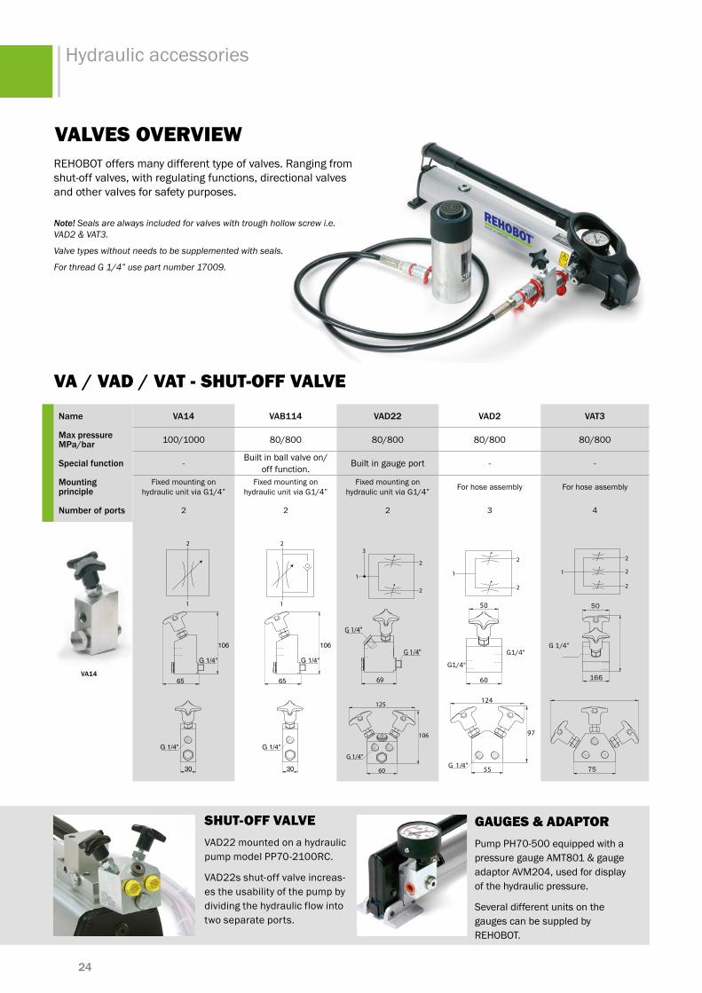
VAlVes oVeRViewREHOBOT offers many different type of valves. Ranging from shut-off valves, with regulating functions, directional valves and other valves for safety purposes.
Note! Seals are always included for valves with trough hollow screw i.e. VAD2 & VAT3.
Valve types without needs to be supplemented with seals.
For thread G 1/4” use part number 17009.
name va14 vab114 vad22 vad2 vat3
Max pressure mpa/bar 100/1000 80/800 80/800 80/800 80/800
special function - Built in ball valve on/off function. Built in gauge port - -
mounting principle
Fixed mounting on hydraulicunitviaG1/4”
Fixed mounting on hydraulicunitviaG1/4”
Fixed mounting on hydraulicunitviaG1/4” For hose assembly For hose assembly
number of ports 2 2 2 3 4
VA / VAd / VAt - shut-oFF VAlVe
va14
50
G1/4”
166
75
1
2
30
G 1/4"
106
65
G 1/4"
30
G 1/4"
106
65
G 1/4"
1
2
1
2
2
60
50
55G 1/4"
124
97
60
50
55G 1/4"
124
97
1
3
2
2
69
G 1/4"
G 1/4"
125
106
6960
G 1/4"G 1/4"
1
2
2
2
shut-oFF VAlVeVAD22 mounted on a hydraulic pump model PP70-2100RC.
VAD22s shut-off valve increas-es the usability of the pump by dividing the hydraulic flow into two separate ports.
GAuGes & AdAptoRPumpPH70-500equippedwithapressure gauge AMT801 & gauge adaptorAVM204,usedfordisplayof the hydraulic pressure.
Several different units on the gauges can be suppled by REHOBOT.
G1/4"
G1/4"
25
Hydraulic accessories
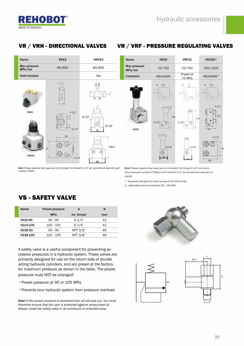
name vr30 vrf31 vr150*
Max pressure mpa/bar 70/700 70/700 150/1500
comment Adjustable Preset at 70 MPa Adjustable1)
name vr42 vrh43
Max pressure mpa/bar 80/800 80/800
hold function - Yes
Note! Please observe that seals are not included. For thread G 1/4” we recommend seal with part number 17009.
VR / VRh - diRectioNAl VAlVes
Vs - sAFety VAlVe
VR / VRF - pRessuRe ReGulAtiNG VAlVes
vr30
vr42
vrh43
Note! Please observe that seals are not included. For thread G 1/4” we recom-
mend seal part number 17009 and for thread G 1/2” we recommend seal part no
14192.
* - Especially designed for hand pumps in the PHS-series.
1) - Adjustable pressure between 50 - 150 MPa.
name preset pressure a b
mpa int. thread mm
vs14-90 90-95 G1/4” 42vs14-100 100-105 G1/4” 42vs38-90 90-95 NPT3/8” 46vs38-100 100-105 NPT3/8” 46
A safety valve is a useful component for preventing ex-cessive pressures in a hydraulic system. These valves are primarily designed for use on the return side of double acting hydraulic cylinders, and are preset at the factory for maximum pressure as shown in the table. The preset pressure must NOT be changed!
•Preset pressure at 95or105MPa.
•Prevents your hydraulic system from pressure overload.
Note! If the preset pressure is exceeded then oil will leak out. You must therefore ensure that the user is protected against pressurised oil. Always install the safety valve in an enclosure or protected area.
G1/4”
60
60
43
25
G1/4”
G1/4”
A
B
38,5
G1/4”
3
1
143
G 1/4"
50
G 1/2"
3
1
120
G 1/4"
50
G 1/2"
A B
P R
75
G 1/4"
130.5
95
G 1/4"
A B
P R
75
G 1/4"
130.5
95
G 1/4"
3
1
120
G 1/4"
50
G 1/2"
3
1
120
G 1/4"
50
G 1/2"
3
1
143
G 1/4"
50
G 1/2"
3
1
143
G 1/4"
50
G 1/2"
A B
P R
75
G 1/4"
130.5
95
G 1/4"
G1/4”
98
72
G1/4”
G1/4”
3
1
143
G 1/4"
50
G 1/2"

26
Hydraulic accessories
* TX103 & TX104 can be connected directly on standard hand pumps within the PHS-serien. Gauge adaptor not required!
name number of scales
measurement range
scale division piston diameter
mm
piston area
cm2
a
mm
b
mm
c
mm
d
mm
e
mm
amp651 5
-40kN 2 kN
304565
71633
G1/2” 137 45 100 18-100 kN 10 kN-200 kN 10 kN-70 MPa 2 MPa
-10000 psi 500psi
amp652 5
-400kN 20 kN
90110140
6495154
G1/2” 137 45 100 18-600 kN 50kN
-1000 kN 50kN-70 MPa 2 MPa
-10000 psi 500psi
amt650 2-100 MPa 2 MPa
G1/2” 137 45 100 18-14000psi 500psi
amt151 2-160 MPa 5MPa
M20x1,5 76,5 45 112 24-23000psi 500psi
amt301 2-310MPa 10 MPa
M20x1,5 76,5 45 112 24-45000psi 1000 psi
amt801 2-100 MPa 5MPa
G1/4” 50 28,5 60 15-15000psi 1000 psi
amZ100 1 -1000 kN 50kN 140 154 G1/2” 137 45 100 18
amZ50 2-500kN 20 kN
100 79 G1/2” 137 45 100 18-50ton
amZ150 2-17 ton 1 ton
55 23,7 G1/2” 137 45 100 18-700 bar 20 bar
amZ250 2-24ton 1 ton
65 33,1 G1/2” 137 45 100 18-700 bar 20 bar
tX102 3-4ton 1 ton
3045
716 G3/8” 130 45 100 18-10 ton 1 ton
-600 bar 50bartX103* 1 -160 MPa 5MPa G1/4” 50 30 66 10,5
tX104* 2-160 MPa 5MPa
G1/4” 50 30 62 9-20000 psi 1000 psi
Amp / Amt / AmZ / tX - pRessuRe GAuGesGauges permit visual monitoring of the force and/or pressure gener-ated by a hydraulic pump. This helps prevent accidental overloading and contributes to prolonging the life of your hydraulic equipment.
Therearealsofluid-dampedgaugemodelsavailablewhicharerec-ommended if there is a risk of pressure surges. Gauges with custom-ised scales can be supplied on request.
AMT801 and TX104 are fluid-damped gauges.AMT801, TX103 and TX104 - these gauges can be connected directly to PHS-series hand pumps. Gauge adapters are not necessary.
amp651amp652amt650amZ100amZ50amZ150amZ250tX102
amt151amt301amt801tX103tX104
A
B
C
E
DB D
C
EA

27
Hydraulic accessories
name for perssure gauge Ext.thread
a
int.thread
b
int.thread
c
Max. pressure
mpa/bar
aam14 AMT801,TX103,TX104 G1/4” - G1/4” 150/1500
aam201 AMP651,AMP652,AMT650,AMZ50,
AMZ100,
G1/4” - G1/2” 100/1000
AMZ150,AMZ250
avm202 AMP651,AMP652,AMT650,AMZ50,
AMZ100,
G1/4” G1/4” G1/2” 100/1000
AMZ150,AMZ250
avm204 AMT801,TX103,TX104 G1/4” G1/4” G1/4” 150/1500
tX111 TX102 G1/4” G1/4” G3/8” 80/800
atm214 AMT801,TX103,TX104 G1/4” G1/4” G1/4” 100/1000
A
C
B
103Ø 30
41,5
AAm / AVm / tX / Atm - GAuGe AdAptoRWhatever combination of pump and gauge you might have, we can offer the right adapter. Gauge adapters AAM201, AVM202 and TX111 have swiveling connection threads for gauge connection. Note! Gauge adaptors needs to be supplemented with additional seals. For thread G 1/4” use part number 17009.
C
A
13
22
C
A 45
25
B A
33.5
75
45
C
B A
33.5
59
45
C
30
A
C
92
56
.5
B
28
Hydraulic accessories
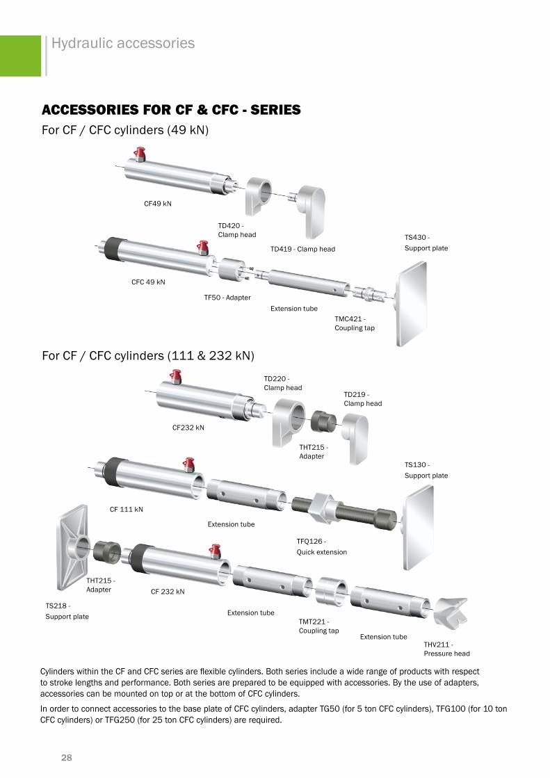
AccessoRies FoR cF & cFc - seRiesForCF/CFCcylinders(49kN)
CylinderswithintheCFandCFCseriesareflexiblecylinders.Bothseriesincludeawiderangeofproductswithrespectto stroke lengths and performance. Both series are prepared to be equipped with accessories. By the use of adapters, accessories can be mounted on top or at the bottom of CFC cylinders.
InordertoconnectaccessoriestothebaseplateofCFCcylinders,adapterTG50(for5tonCFCcylinders),TFG100(for10tonCFCcylinders)orTFG250(for25tonCFCcylinders)arerequired.
ForCF/CFCcylinders(111&232kN)
TD420- Clamp head
TD419-Clamphead
TF50-AdapterExtension tube
TMC421- Coupling tap
TS430-Support plate
TD220 - Clamp head
TD219- Clamp head
THT215- Adapter
Extension tube
Extension tube
Extension tube
TFQ126 - Quick extension
TS130-Support plate
TMT221 - Coupling tap
THV211 - Pressure head
CF49kN
CFC49kN
CF232kN
CF 111 kN
CF232kNTHT215- Adapter
TS218 - Support plate
29
Hydraulic accessories
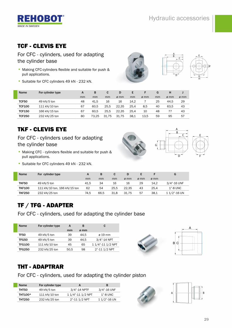
• Making CFC-cylindersflexibleandsuitableforpush& pull applications.
• SuitableforCFCcylinders49kN-232kN.
name for cylinder type a b c d e f g h Jmm mm mm ø mm mm ø mm mm ø mm ø mm
tcf50 49kN/5ton 48 41,5 16 16 14,2 7 25 44,5 29tcf100 111 kN/10 ton 67 60,5 25,5 22,35 25,4 8,5 40 63,5 43tcf150 166kN/15ton 67 60,5 25,5 22,35 25,4 10 48 77 43tcf250 232kN/25ton 80 73,25 31,75 31,75 38,1 13,5 59 95 57
tKF - cleVis eye For CFC - cylinders used for adapting the cylinder base• Making CFC-cylindersflexibleandsuitableforpush& pull applications.
• SuitableforCFCcylinders49kN-232kN.
name for cylinder type a b c d e f gmm mm mm ø mm ø mm ø mm
tkf50 49kN/5ton 41,5 34 16 16 29 14,2 3/4”-16UNFtkf100 111kN/10ton,166kN/15ton 62 54 25,5 22,35 43 25,4 1”-8UNCtkf250 232kN/25ton 74,5 66,5 31,8 31,75 57 38,1 11/2”-16UN
tF / tFG - AdApteR For CFC - cylinders, used for adapting the cylinder base
name for cylinder type a b cmm ø mm
tf50 49kN/5ton 39 44,5 ø19mmtfg50 49kN/5ton 39 44,5 3/4”-14NPTtfg100 111 kN/10 ton 45 65 11/4”-111/2NPTtfg250 232kN/25ton 50,5 98 2”-111/2NPT
name for cylinder type a btht50 49kN/5ton 3/4”-14NPTF 3/4”-16UNFtht100* 111 kN/10 ton 11/4”-111/2NPT 1”-8UNCtht250 232kN/25ton 2”-111/2NPT 11/2”-16UN
tht - AdAptRARFor CFC - cylinders, used for adapting the cylinder piston
tcF - cleVis eye For CFC - cylinders, used for adapting the cylinder base
GH
F
AB
C
D
E
GH
F
AB
C
D
E
C
D
A
G
E
F
BC
D
A
G
E
F
B
A B
CB
A
30
Hydraulic accessories
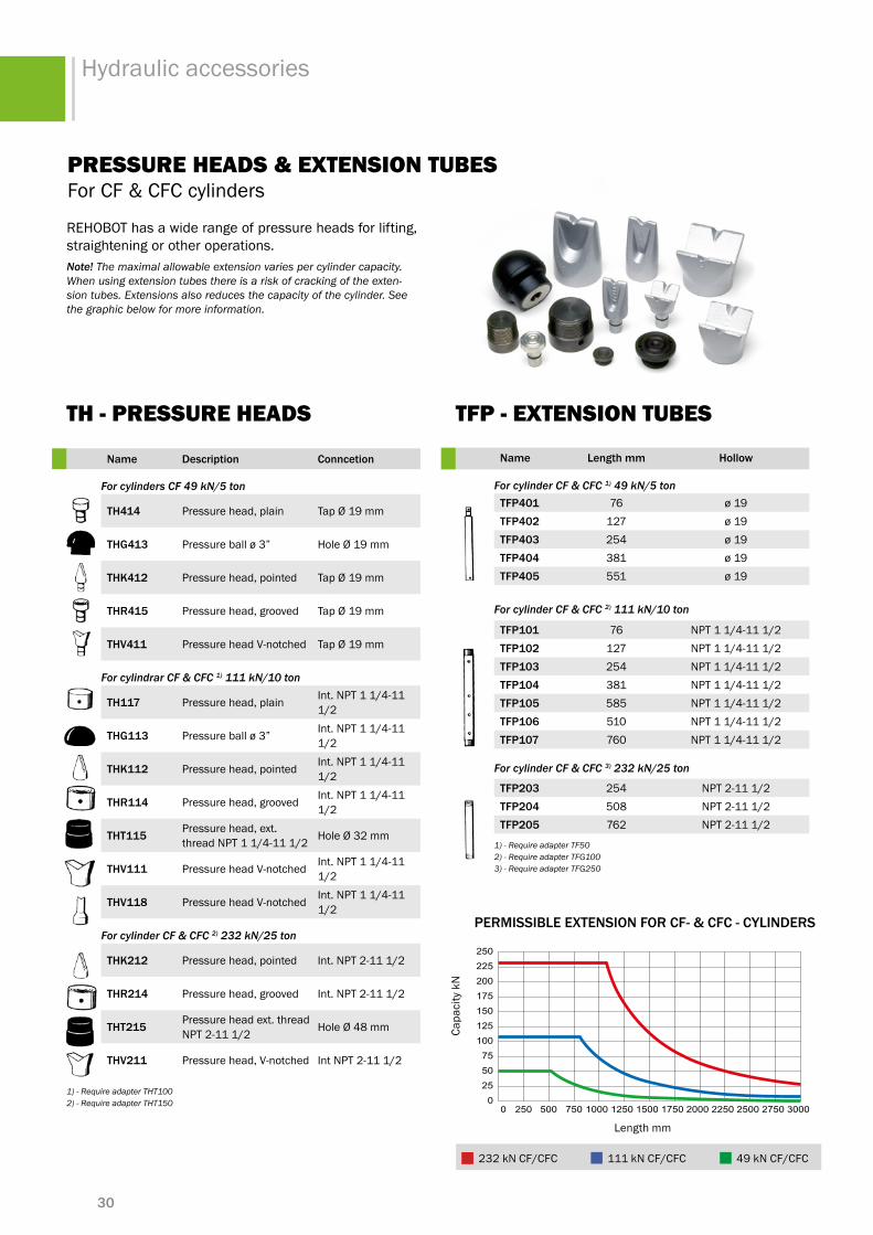
name length mm hollow
For cylinder CF & CFC 1) 49 kN/5 tontfp401 76 ø19tfp402 127 ø19tfp403 254 ø19tfp404 381 ø19tfp405 551 ø19
For cylinder CF & CFC 2) 111 kN/10 ton
tfp101 76 NPT11/4-111/2tfp102 127 NPT11/4-111/2tfp103 254 NPT11/4-111/2tfp104 381 NPT11/4-111/2tfp105 585 NPT11/4-111/2tfp106 510 NPT11/4-111/2tfp107 760 NPT11/4-111/2
For cylinder CF & CFC 3) 232 kN/25 ton
tfp203 254 NPT 2-11 1/2tfp204 508 NPT 2-11 1/2tfp205 762 NPT 2-11 1/2
1) - Require adapter TF50 2) - Require adapter TFG100 3) - Require adapter TFG250
00 250 1250 2500 3000275022502000175015001000750500
255075
100125150175200225250
232 kN CF/CFC111 kN CF/CFC 49 kN CF/CFC
Lenght(mm)
Lenght (mm)
Extension
Capacity(kN)
Graph of max. permissible extension/capacity of CF and CFC rams
Ram
pRessuRe heAds & eXteNsioN tuBes For CF & CFC cylinders
name description conncetion
For cylinders CF 49 kN/5 ton
th414 Pressure head, plain TapØ19mm
thg413 Pressureballø3” HoleØ19mm
thk412 Pressure head, pointed TapØ19mm
thr415 Pressure head, grooved TapØ19mm
thv411 Pressure head V-notched Tap Ø19mm
For cylindrar CF & CFC 1) 111 kN/10 ton
th117 Pressure head, plain Int.NPT11/4-111/2
thg113 Pressureballø3” Int.NPT11/4-111/2
thk112 Pressure head, pointed Int.NPT11/4-111/2
thr114 Pressure head, grooved Int.NPT11/4-111/2
tht115 Pressure head, ext. threadNPT11/4-111/2 Hole Ø 32mm
thv111 Pressure head V-notched Int.NPT11/4-111/2
thv118 Pressure head V-notched Int.NPT11/4-111/2
For cylinder CF & CFC 2) 232 kN/25 ton
thk212 Pressure head, pointed Int. NPT 2-11 1/2
thr214 Pressure head, grooved Int. NPT 2-11 1/2
tht215 Pressure head ext. thread NPT 2-11 1/2 HoleØ48mm
thv211 Pressure head, V-notched Int NPT 2-11 1/2
1) - Require adapter THT100 2) - Require adapter THT150
REHOBOT has a wide range of pressure heads for lifting, straightening or other operations.Note! The maximal allowable extension varies per cylinder capacity. When using extension tubes there is a risk of cracking of the exten-sion tubes. Extensions also reduces the capacity of the cylinder. See the graphic below for more information.
th - pRessuRe heAds tFp - eXteNsioN tuBes
permissible eXtension for cf- & cfc - cylinders
Length mm
Capa
city
kN
232kNCF/CFC 111 kN CF/CFC 49kNCF/CFC
31
Hydraulic accessories
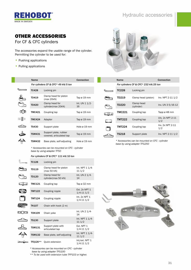
name connection
For cylinders CF & CFC* 49 kN/5 ton
tc428 Locking pin -
td419 Clamp head for piston(max 20kN) Tapø19mm
td420 Clamp head for cylinder(max 20kN)
Int. UN 1 1/2-16
tmc421 Coupling tap Tapø19mm
tmc424 Adapter Tapø19mm
ts430 Support plate Holeø19mm
tsm431 Support plate, rubber covered, articulated tap Tapø19mm
tsm432 Base plate, self-adjusting Holeø19mm
* Accessories can be mounted on CFC - cylinder base by using adapter TF50
For cylinders CF & CFC* 111 kN/10 ton
tc128 Locking pin
td119 Clamp head for piston(max50kN)
Int.NPT11/4-11 1/2
td120 Clamp head for cylinder(max50kN)
Int.UN21/4-14
tmc121 Coupling tap Tapø32mm
tmt122 Coupling nipple Ext. 2x NPT 1 1/4-111/2
tmt124 Coupling nipple Int. 2x NPT 1 1/4-111/2
tk107 Chain with hook (2 m)
tok109 Chain yoke Int.UN21/4-14
ts130 Support plate Int.NPT11/4-11 1/2
tsm131 Support plate with articulated tap
Ext. NPT 1 1/4-111/2
tsm132 Base plate, self-adjusting Int.NPT11/4-11 1/2
tfQ126** Quick extension Int/ext. NPT 1 1/4-111/2
* Accessories can be mounted on CFC - cylinder base by using adapter TFG100** To be used with extension tube TFP103 or higher.
otheR AccessoRies For CF & CFC cylinders The accessories expand the usable range of the cylinder. Permitting the cylinder to be used for:
• Pushing applications
• Pulling applications
name connection
For cylinders CF & CFC* 232 kN/25 ton
tc228 Locking pin -
td219 Clamp head (piston) Inv. NPT 2-11 1/2
td220 Clamp head (cylinder) Inv.UN35/16-12
tmc221 Coupling tap Tappø48mm
tmt222 Coupling tap Utv. 2x NPT 2-11 1/2
tmt224 Coupling tap Inv. 2x NPT 2-11 1/2
ts218 Support plate Inv. NPT 2-11 1/2
* Accessories can be mounted on CFC - cylinder base by using adapter TFG250
32
Hydraulic accessories
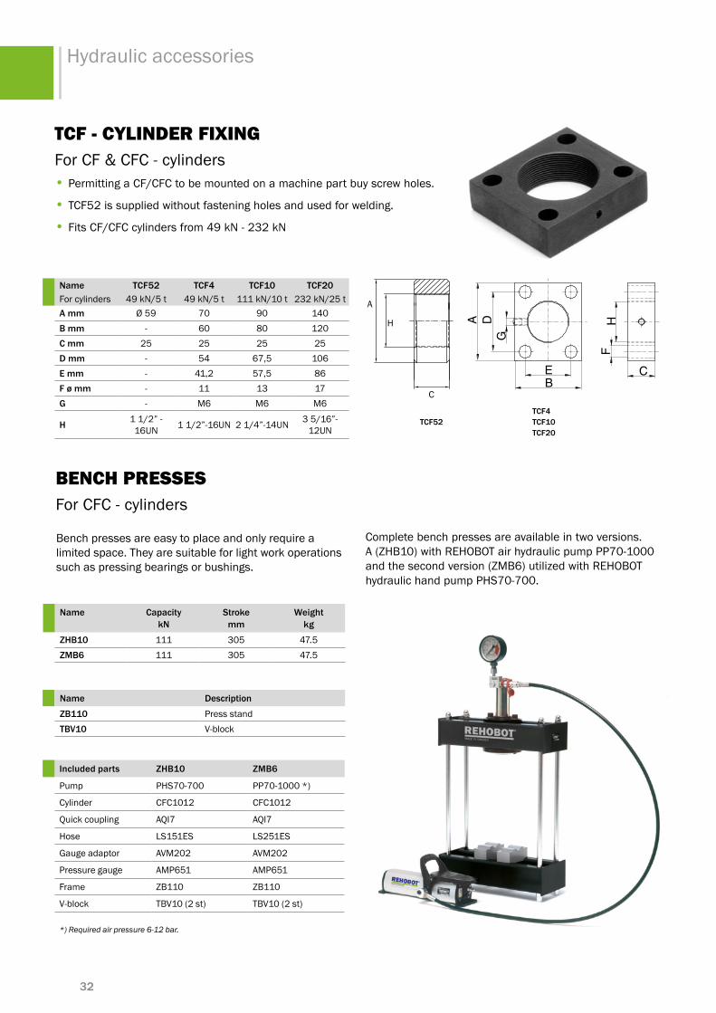
Bench presses are easy to place and only require a limited space. They are suitable for light work operations such as pressing bearings or bushings.
BeNch pRessesFor CFC - cylinders
Complete bench presses are available in two versions. A(ZHB10)withREHOBOTairhydraulicpumpPP70-1000andthesecondversion(ZMB6)utilizedwithREHOBOThydraulic hand pump PHS70-700.
name description
Zb110 Press standtbv10 V-block
included parts Zhb10 Zmb6
Pump PHS70-700 PP70-1000*)
Cylinder CFC1012 CFC1012
Quick coupling AQI7 AQI7
Hose LS151ES LS251ES
Gauge adaptor AVM202 AVM202
Pressure gauge AMP651 AMP651
Frame ZB110 ZB110
V-block TBV10 (2 st) TBV10 (2 st)
*) Required air pressure 6-12 bar.
name capacitykn
stroke mm
Weight kg
Zhb10 111 305 47.5Zmb6 111 305 47.5
tcF - cyliNdeR FiXiNGFor CF & CFC - cylinders• Permitting a CF/CFC to be mounted on a machine part buy screw holes.
• TCF52issuppliedwithoutfasteningholesandusedforwelding.
• FitsCF/CFCcylindersfrom49kN-232kN
name tcf52 tcf4 tcf10 tcf20For cylinders 49kN/5t 49kN/5t 111 kN/10 t 232kN/25ta mm Ø59 70 90 140b mm - 60 80 120c mm 25 25 25 25d mm - 54 67,5 106e mm - 41,2 57,5 86f ø mm - 11 13 17g - M6 M6 M6
h 11/2”-16UN 11/2”-16UN 21/4”-14UN 35/16”-
12UN
C
H
A
tcf52tcf4tcf10tcf20
A D H
G
F
E CB
A D H
G
F
E CB

33
Hydraulic accessories
AccessoRies FoR chF & chFA - seRies th - sAddlesFor CHF & CHFA - cylindersAccessory saddles for hollow cylinders type CHF and CHFA, 6 to 100 tonnes.
For pressing or lifting applications it is recommended to use the grooved solid saddles (THR). We also offer two more types; with inner metric (THM) and UN (THU) threads. The saddles THH are supplied as standard on all CHFA cylinders.
name for cylinder inner dimension
thh6 - -
thm6 CH/CHF62 M16
thu6 CH/CHF62 5/8”-11UNC
thr6 CH/CHF62 Solid with grooves
thh13 CHFA132/136 Ø22 mm - standard
thm13 CHFA132/136 M20
thu13 CHFA132/136 3/4”-10UNC
thr13 CHFA132/136 Solid with grooves
thh18 CHFA182/184 Ø26 mm - standard
thm18 CHFA182/184 M24
thu18 CHFA182/184 1”-8UNC
thr18 CHFA182/184 Solid with grooves
thh26 CHFA262/266 Ø32mm-standard
thm26 CHFA262/266 M30
name for cylinder inner dimension
thu26 CHFA262/266 11/4”-7UNC
thr26 CHFA262/266 Solid with grooves
thh37 CHFA372/374 Ø39mm-standard
thm37 CHFA372/374 M36
thu37 CHFA372/374 13/8”-6UNC
thr37 CHFA372/374 Solid with grooves
thh67 CHFA673/676 Ø54-standard
thm67 CHFA673/676 M52
thu67 CHFA673/676 2”-4UNC
thr67 CHFA673/676 Solid with grooves
thh100 CHFA1003/1006 Ø66 - standard
thm100 CHFA1003/1006 M64
thu100 CHFA1003/1006 21/2”-4UNC
thr100 CHFA1003/1006 Solid with grooves
ts - cyliNdeR suppoRt plAteFor CHFA - cylindersCylinder support plates suitable for CHFA single acting aluminium hollow cylinders are made of steel and are used for protecting the cylinder base against damages. TS cylinder support plates should always be used when the cylinder base is placed against hard material. A support plate is a simple and cost effective way to protect your cylinder.
name for cylinderkn
Weight kg
ts13 CHFA132/136 0,1ts18 CHFA182/184 0,2ts26 CHFA262/266 0,5
name for cylinderkn
Weight kg
ts37 CHFA372/376 0,7ts67 CHFA673/676 1,5ts100 CHFA1003/1006 2,8

34
Hydraulic accessories
name description connection
tb441 Pull shackle Int.NPT3/4-14
tbk410 Shackle with bolt -
tk408 Chain with hook (1600 mm) -
tmk427 Chain attachment Int.NPT3/4-14
tmt422 Coupling nipple Ext.2xNPT3/4-14
tmt423 Coupling nippleInt.NPT3/4-14 Ext.NPT11/4-111/2
name description conections
tb141 Pull shackle Int.NPT11/4-111/2
tbk110 Shackle with bolt -
tk107 Chain with hook (2000 mm) -
tmk127 Chain attachment Int.NPT11/4-111/2
tmt122 Coupling nipple Ext.2xNPT11/4-111/2
ForcylinderCPF709(111kN)
ForcylinderCPF704(49kN)AccessoRies FoR cpF - seRies
Accessories for CPF - pull cylinders makes it easy to direct the power where you need it.
ThepictureshowsaCPF705-cylin-derwithTK406-Chain&TMK427- bracket to power a brake test.
tb441
tmk427
ApplicAtioN eXAmple

35
Hydraulic accessories
moRe iNFoRmAtioN - www.rehobot.se On our website we have gathered important information about our cylinders and other products from REHOBOT.Youcanforinstancefindinformationaboutthedimensionsofourproducts,companypresenta-tion,accessories,applicationsandmuchmore.YoucanalsodownloadQualityandenvironmentalcertifi-cates, Declaration of Conformation and other related product documents.
100 BAR
Power with hydraulics
www.rehobot.se
PRODUCT OVERVIEW
SAFETYCUTTERS, SPREADERS, RESCUE PUMPS, PIPE SEALING TOOLS, DOOR OPENERS, RESCUE KITS, MANUAL TOOLS, RAMS
RESCUE EQUIPMENT
res
cue
eQui
pmen
t • Spreaders
• Hydraulic cutters
• Pipe sealing kit
• Door openers
• Rescue pumps
• Rescue kit
otheR cAtAloGues For information about the complete product range of REHOBOT, please contact us.
lift
ing
sys
tem
s
• Bottle jacks
• Axle stands
• Lifting systems
• Fork lift jacks
• Trolley jacks
• Bottle jacks
• Transmission jacks
POWER WITH HYDRAULICS
www.rehobot.se
PRODUCT OVERVIEW LIFTING SYSTEM
20 TONGARAGEDOMKRAFTER, HANDDOM-KRAFTER, PALLBOCKAR, VERKSTADS-LYFTAR, SPECIALLYFTAR

rehobot hydraulics abP.O. Box 1107SE-63180Eskilstuna,SWEDENT:+46(0)16168200F:+46(0)[email protected]
rehobot inc (usa)3980W.Albany,Unit#1MCHENRY,IL60050,USAT:+18153857777F:[email protected]
rehobot ltd (uk)Unit 6, Stechford Trading EstateLyndon Road, StechfordBIRMINGHAMB338BU,UKT:+441217897707F:[email protected]
www.rehobot.se
rehobot ltd (china)4F2HengLiBuildingNo.5HuangLong Rd Xihu DistrictHangzhou,310013P.R.CT:+8657187106106F:[email protected]
REHOBOT HYDRAULICS ABSince 1924 we have developed, manufactured and marketed high-pressure hydraulic solutions for service & maintenance purposes. The products can be found within the areas covered by our three business areas, Industrial, Automotive and Rescue.
Our headquarter is situated in Eskilstuna, Sweden. Today REHOBOT deliver high-pressure hydraulics worldwide. Success for us involve exceeding limita-tions and to develop smart solutions for our customers’ power problems.
REHOBOT HYDRAULICS stands for Quality, Reliability & Service. Our products are marketed by ourselves but also through dealers. We have subsidiaries in the U.S., England and China. In addition to these, we work with partners in more than 70 countries which always ensure that our customers receive the best possible service, wherever they are!
”HYDRAULICS WITH BUILT-IN NATURAL FORCES USED IN A VAST NUmBER OF APPLICATIONS”
Visit our website Keep updated by visiting REHOBOT on the Internet. On our site you find the latest information about our products, contact information to your local REHOBOT - dealer, dates for future exhibitions, catalogues for download & much more.
www.rehobot.se
We reserve the right to change product-related information and technical specifications without prior notice.
MJO/2012-03-28