power systems: racks and rack features
TRANSCRIPT

Power Systems
Racks and rack features
���


Power Systems
Racks and rack features
���

NoteBefore using this information and the product it supports, read the information in “Safety notices” on page v, “Notices” onpage 51, the IBM Systems Safety Notices manual, G229-9054, and the IBM Environmental Notices and User Guide, Z125–5823.
This edition applies to IBM Power Systems™ servers that contain the POWER7 processor and to all associatedmodels.
© Copyright IBM Corporation 2012, 2013.US Government Users Restricted Rights – Use, duplication or disclosure restricted by GSA ADP Schedule Contractwith IBM Corp.

Contents
Safety notices . . . . . . . . . . . . . . . . . . . . . . . . . . . . . . . . . v
Racks and rack features. . . . . . . . . . . . . . . . . . . . . . . . . . . . . 1What's new in Racks and rack features . . . . . . . . . . . . . . . . . . . . . . . . . . 1Installing the rack . . . . . . . . . . . . . . . . . . . . . . . . . . . . . . . . . 1
7014-T00 and 7014-T42 racks . . . . . . . . . . . . . . . . . . . . . . . . . . . . . 1Installing the 7014-T00 and 7014-T42 racks . . . . . . . . . . . . . . . . . . . . . . . 1
Completing a parts inventory. . . . . . . . . . . . . . . . . . . . . . . . . . . 1Positioning the rack . . . . . . . . . . . . . . . . . . . . . . . . . . . . . . 2Leveling the rack . . . . . . . . . . . . . . . . . . . . . . . . . . . . . . . 2Attaching the stabilizer brackets . . . . . . . . . . . . . . . . . . . . . . . . . . 3Attaching the rack to a concrete floor . . . . . . . . . . . . . . . . . . . . . . . . 4Attaching the rack to the concrete floor beneath a raised floor . . . . . . . . . . . . . . . . 9Connecting the power distribution system . . . . . . . . . . . . . . . . . . . . . . 13Checking the ac outlets . . . . . . . . . . . . . . . . . . . . . . . . . . . . 13Attaching the front or back ac electrical outlet . . . . . . . . . . . . . . . . . . . . . 14Connecting a dc power source . . . . . . . . . . . . . . . . . . . . . . . . . . 17
Removing and replacing 7014-T00 or 7014-T42 side panels. . . . . . . . . . . . . . . . . . 21Removing a 7014-T00 or 7014-T42 side panel . . . . . . . . . . . . . . . . . . . . . 21Replacing a 7014-T00 or 7014-T42 side panel . . . . . . . . . . . . . . . . . . . . . 22
Removing and replacing 7014-T00 or 7014-T42 trim panels . . . . . . . . . . . . . . . . . 22Removing the 7014-T00 or 7014-T42 trim panels . . . . . . . . . . . . . . . . . . . . 22Replacing the 7014-T00 or 7014-T42 trim panels . . . . . . . . . . . . . . . . . . . . 23
Attaching the rack doors . . . . . . . . . . . . . . . . . . . . . . . . . . . . . 24Attaching a high-perforation front door . . . . . . . . . . . . . . . . . . . . . . . 25Rack safety notices . . . . . . . . . . . . . . . . . . . . . . . . . . . . . . 26
Installing the rack security kit . . . . . . . . . . . . . . . . . . . . . . . . . . . 28Ruggedized kit . . . . . . . . . . . . . . . . . . . . . . . . . . . . . . . . 30
Releasing the ruggedized brace . . . . . . . . . . . . . . . . . . . . . . . . . . 31Releasing the side panel with a ruggedized kit . . . . . . . . . . . . . . . . . . . . 32
Connecting multiple racks with rack-to-rack attachment kit . . . . . . . . . . . . . . . . . 33Removing and replacing the rack top cover. . . . . . . . . . . . . . . . . . . . . . . 35
Removing the rack top cover . . . . . . . . . . . . . . . . . . . . . . . . . . 35Replacing the rack top cover . . . . . . . . . . . . . . . . . . . . . . . . . . 37
Power distribution unit . . . . . . . . . . . . . . . . . . . . . . . . . . . . . 39Installing the PDU or PDU+ in the side of a rack . . . . . . . . . . . . . . . . . . . . 39Setting up power monitoring using the PDU+ . . . . . . . . . . . . . . . . . . . . . 45
Notices . . . . . . . . . . . . . . . . . . . . . . . . . . . . . . . . . . . 51Trademarks . . . . . . . . . . . . . . . . . . . . . . . . . . . . . . . . . . . 52Electronic emission notices . . . . . . . . . . . . . . . . . . . . . . . . . . . . . . 52
Class A Notices . . . . . . . . . . . . . . . . . . . . . . . . . . . . . . . . . 52Class B Notices . . . . . . . . . . . . . . . . . . . . . . . . . . . . . . . . . 56
Terms and conditions . . . . . . . . . . . . . . . . . . . . . . . . . . . . . . . . 59
© Copyright IBM Corp. 2012, 2013 iii

iv Power Systems: Racks and rack features
Safety notices
Safety notices may be printed throughout this guide:v DANGER notices call attention to a situation that is potentially lethal or extremely hazardous to
people.v CAUTION notices call attention to a situation that is potentially hazardous to people because of some
existing condition.v Attention notices call attention to the possibility of damage to a program, device, system, or data.
World Trade safety information
Several countries require the safety information contained in product publications to be presented in theirnational languages. If this requirement applies to your country, safety information documentation isincluded in the publications package (such as in printed documentation, on DVD, or as part of theproduct) shipped with the product. The documentation contains the safety information in your nationallanguage with references to the U.S. English source. Before using a U.S. English publication to install,operate, or service this product, you must first become familiar with the related safety informationdocumentation. You should also refer to the safety information documentation any time you do notclearly understand any safety information in the U.S. English publications.
Replacement or additional copies of safety information documentation can be obtained by calling the IBMHotline at 1-800-300-8751.
German safety information
Das Produkt ist nicht für den Einsatz an Bildschirmarbeitsplätzen im Sinne § 2 derBildschirmarbeitsverordnung geeignet.
Laser safety information
IBM® servers can use I/O cards or features that are fiber-optic based and that utilize lasers or LEDs.
Laser compliance
IBM servers may be installed inside or outside of an IT equipment rack.
© Copyright IBM Corp. 2012, 2013 v

DANGER
When working on or around the system, observe the following precautions:
Electrical voltage and current from power, telephone, and communication cables are hazardous. Toavoid a shock hazard:v Connect power to this unit only with the IBM provided power cord. Do not use the IBM
provided power cord for any other product.v Do not open or service any power supply assembly.v Do not connect or disconnect any cables or perform installation, maintenance, or reconfiguration
of this product during an electrical storm.v The product might be equipped with multiple power cords. To remove all hazardous voltages,
disconnect all power cords.v Connect all power cords to a properly wired and grounded electrical outlet. Ensure that the outlet
supplies proper voltage and phase rotation according to the system rating plate.v Connect any equipment that will be attached to this product to properly wired outlets.v When possible, use one hand only to connect or disconnect signal cables.v Never turn on any equipment when there is evidence of fire, water, or structural damage.v Disconnect the attached power cords, telecommunications systems, networks, and modems before
you open the device covers, unless instructed otherwise in the installation and configurationprocedures.
v Connect and disconnect cables as described in the following procedures when installing, moving,or opening covers on this product or attached devices.
To Disconnect:1. Turn off everything (unless instructed otherwise).2. Remove the power cords from the outlets.3. Remove the signal cables from the connectors.4. Remove all cables from the devices.
To Connect:1. Turn off everything (unless instructed otherwise).2. Attach all cables to the devices.3. Attach the signal cables to the connectors.4. Attach the power cords to the outlets.5. Turn on the devices.
(D005)
DANGER
vi Power Systems: Racks and rack features

Observe the following precautions when working on or around your IT rack system:
v Heavy equipment–personal injury or equipment damage might result if mishandled.
v Always lower the leveling pads on the rack cabinet.
v Always install stabilizer brackets on the rack cabinet.
v To avoid hazardous conditions due to uneven mechanical loading, always install the heaviestdevices in the bottom of the rack cabinet. Always install servers and optional devices startingfrom the bottom of the rack cabinet.
v Rack-mounted devices are not to be used as shelves or work spaces. Do not place objects on topof rack-mounted devices.
v Each rack cabinet might have more than one power cord. Be sure to disconnect all power cords inthe rack cabinet when directed to disconnect power during servicing.
v Connect all devices installed in a rack cabinet to power devices installed in the same rackcabinet. Do not plug a power cord from a device installed in one rack cabinet into a powerdevice installed in a different rack cabinet.
v An electrical outlet that is not correctly wired could place hazardous voltage on the metal parts ofthe system or the devices that attach to the system. It is the responsibility of the customer toensure that the outlet is correctly wired and grounded to prevent an electrical shock.
CAUTION
v Do not install a unit in a rack where the internal rack ambient temperatures will exceed themanufacturer's recommended ambient temperature for all your rack-mounted devices.
v Do not install a unit in a rack where the air flow is compromised. Ensure that air flow is notblocked or reduced on any side, front, or back of a unit used for air flow through the unit.
v Consideration should be given to the connection of the equipment to the supply circuit so thatoverloading of the circuits does not compromise the supply wiring or overcurrent protection. Toprovide the correct power connection to a rack, refer to the rating labels located on theequipment in the rack to determine the total power requirement of the supply circuit.
v (For sliding drawers.) Do not pull out or install any drawer or feature if the rack stabilizer bracketsare not attached to the rack. Do not pull out more than one drawer at a time. The rack mightbecome unstable if you pull out more than one drawer at a time.
v (For fixed drawers.) This drawer is a fixed drawer and must not be moved for servicing unlessspecified by the manufacturer. Attempting to move the drawer partially or completely out of therack might cause the rack to become unstable or cause the drawer to fall out of the rack.
(R001)
Safety notices vii

CAUTION:Removing components from the upper positions in the rack cabinet improves rack stability duringrelocation. Follow these general guidelines whenever you relocate a populated rack cabinet within aroom or building:
v Reduce the weight of the rack cabinet by removing equipment starting at the top of the rackcabinet. When possible, restore the rack cabinet to the configuration of the rack cabinet as youreceived it. If this configuration is not known, you must observe the following precautions:
– Remove all devices in the 32U position and above.
– Ensure that the heaviest devices are installed in the bottom of the rack cabinet.
– Ensure that there are no empty U-levels between devices installed in the rack cabinet below the32U level.
v If the rack cabinet you are relocating is part of a suite of rack cabinets, detach the rack cabinet fromthe suite.
v Inspect the route that you plan to take to eliminate potential hazards.
v Verify that the route that you choose can support the weight of the loaded rack cabinet. Refer to thedocumentation that comes with your rack cabinet for the weight of a loaded rack cabinet.
v Verify that all door openings are at least 760 x 230 mm (30 x 80 in.).
v Ensure that all devices, shelves, drawers, doors, and cables are secure.
v Ensure that the four leveling pads are raised to their highest position.
v Ensure that there is no stabilizer bracket installed on the rack cabinet during movement.
v Do not use a ramp inclined at more than 10 degrees.
v When the rack cabinet is in the new location, complete the following steps:
– Lower the four leveling pads.
– Install stabilizer brackets on the rack cabinet.
– If you removed any devices from the rack cabinet, repopulate the rack cabinet from the lowestposition to the highest position.
v If a long-distance relocation is required, restore the rack cabinet to the configuration of the rackcabinet as you received it. Pack the rack cabinet in the original packaging material, or equivalent.Also lower the leveling pads to raise the casters off of the pallet and bolt the rack cabinet to thepallet.
(R002)
(L001)
(L002)
viii Power Systems: Racks and rack features

(L003)
or
All lasers are certified in the U.S. to conform to the requirements of DHHS 21 CFR Subchapter J for class1 laser products. Outside the U.S., they are certified to be in compliance with IEC 60825 as a class 1 laserproduct. Consult the label on each part for laser certification numbers and approval information.
CAUTION:This product might contain one or more of the following devices: CD-ROM drive, DVD-ROM drive,DVD-RAM drive, or laser module, which are Class 1 laser products. Note the following information:
v Do not remove the covers. Removing the covers of the laser product could result in exposure tohazardous laser radiation. There are no serviceable parts inside the device.
v Use of the controls or adjustments or performance of procedures other than those specified hereinmight result in hazardous radiation exposure.
(C026)
Safety notices ix

CAUTION:Data processing environments can contain equipment transmitting on system links with laser modulesthat operate at greater than Class 1 power levels. For this reason, never look into the end of an opticalfiber cable or open receptacle. (C027)
CAUTION:This product contains a Class 1M laser. Do not view directly with optical instruments. (C028)
CAUTION:Some laser products contain an embedded Class 3A or Class 3B laser diode. Note the followinginformation: laser radiation when open. Do not stare into the beam, do not view directly with opticalinstruments, and avoid direct exposure to the beam. (C030)
CAUTION:The battery contains lithium. To avoid possible explosion, do not burn or charge the battery.
Do Not:v ___ Throw or immerse into waterv ___ Heat to more than 100°C (212°F)v ___ Repair or disassemble
Exchange only with the IBM-approved part. Recycle or discard the battery as instructed by localregulations. In the United States, IBM has a process for the collection of this battery. For information,call 1-800-426-4333. Have the IBM part number for the battery unit available when you call. (C003)
Power and cabling information for NEBS (Network Equipment-Building System)GR-1089-CORE
The following comments apply to the IBM servers that have been designated as conforming to NEBS(Network Equipment-Building System) GR-1089-CORE:
The equipment is suitable for installation in the following:v Network telecommunications facilitiesv Locations where the NEC (National Electrical Code) applies
The intrabuilding ports of this equipment are suitable for connection to intrabuilding or unexposedwiring or cabling only. The intrabuilding ports of this equipment must not be metallically connected to theinterfaces that connect to the OSP (outside plant) or its wiring. These interfaces are designed for use asintrabuilding interfaces only (Type 2 or Type 4 ports as described in GR-1089-CORE) and require isolationfrom the exposed OSP cabling. The addition of primary protectors is not sufficient protection to connectthese interfaces metallically to OSP wiring.
Note: All Ethernet cables must be shielded and grounded at both ends.
The ac-powered system does not require the use of an external surge protection device (SPD).
The dc-powered system employs an isolated DC return (DC-I) design. The DC battery return terminalshall not be connected to the chassis or frame ground.
x Power Systems: Racks and rack features

Racks and rack features
Learn about the procedures used to install racks and rack features.
You can perform these tasks or contact a service provider to perform the tasks for you. You might becharged a fee by the service provider for this service.
What's new in Racks and rack featuresRead about new or significantly changed information in Racks and rack features since the previousupdate of this topic collection.
November 2013v Removed reference to 7953-94Y racks.
March 2013
Content updates include the following:v Miscellaneous changes were made to the Installing the PDU or PDU+ in the side of a rack topic.
October 2012
Content updates include the following:v Added link to information about planning and installing the IBM PureFlex™ System 42U Rack
(7953-94X) and the IBM 42U Slim Rack (7953-94Y).
Installing the rackUse this information to find the planning and installation procedures for the 7014-T00 and 7014-T42 racksand the 7953-94X rack.
7014-T00 and 7014-T42 racksUse this information to install the 7014-T00 and 7014-T42 racks and to install the related components ofthe racks system.
Installing the 7014-T00 and 7014-T42 racksUse this information to install the 7014-T00 and 7014-T42 racks.
If you are installing a rack security kit in this rack, see “Installing the rack security kit” on page 28 afteryou have installed the rack.
Before installing a rack, read the “Rack safety notices” on page 26.
Completing a parts inventory:
Before beginning the rack installation it is a good idea to do a parts inventory. This section guides you inperforming this task.
If you have not done so, complete a parts inventory before installing the unit in the rack:1. Locate the kitting report in an accessory box.2. Ensure that you received all of the features that you ordered and all of the parts on the kitting report.
© Copyright IBM Corp. 2012, 2013 1

If there are incorrect, missing, or damaged parts, contact:v Your IBM resellerv IBM support (see Directory of worldwide contacts website at IBM Directory of worldwide contacts -
Country/region for contact information for your country)v IBM Rochester Manufacturing Automated Information Line at 1–800–300–8751 (United States only)
Positioning the rack:
Proper rack positioning is needed to comply with safety and regulatory requirements. Use the procedurein this section to perform this task.
After the rack has been placed into its location on the floor, lock each caster by tightening the lockingscrew. See the following illustration for the locking screw location (2). Remove all the tape and packingmaterials from the rack.
1 Caster2 Locking screw
Use the following to determine the next step:v To bolt the rack to a concrete floor, go to “Attaching the rack to a concrete floor” on page 4.v To bolt the rack to a concrete floor beneath a raised floor, go to “Attaching the rack to the concrete
floor beneath a raised floor” on page 9.v To attach the rack to the floor, go to “Leveling the rack.”
Leveling the rack:
If you need to level the rack, use the procedure described in this section.
To level the rack, complete the following steps:1. Loosen the jam nut on each leveling foot.2. Rotate each leveling foot downward until it contacts the surface on which the rack is placed.
Figure 1. Tightening the locking screw
2 Power Systems: Racks and rack features

3. Adjust the leveling feet downward as needed until the rack is level. When the rack is level, tightenthe jam nuts against the base.
1 Rack Front (base)2 Leveling Foot (quantity 4)3 Jam Nut (quantity 4)
Attaching the stabilizer brackets:
You might need to attach the stabilizer brackets to the rack. This section helps you determine whetherstabilizer brackets are necessary and describes how to attach them if needed.
If the front or back ac electrical outlets are going to be installed in the rack, you cannot attach thestabilizer brackets. The rack must be bolted to the floor. Stabilizer brackets are used only if you will notbe bolting the rack to the floor. If you are going to bolt the rack to the floor, go to “Attaching the rack toa concrete floor” on page 4.
To attach the stabilizer brackets to the bottom of the rack, complete the following steps:
Note: Before installing the stabilizer brackets, see “Attaching the front or back ac electrical outlet” onpage 14 for instruction about installing the ac outlet-mounting plates.1. Align the slots of one of the stabilizer brackets with the mounting holes at the bottom front of the
rack.2. Install the two mounting screws.3. Ensure that the base of the stabilizer bracket rests firmly on the floor. Use the Allen wrench that was
supplied with the rack to tighten the mounting screws alternately until they are tight.
Figure 2. Adjusting the leveling feet
Racks and rack features 3

1 Rack front (base) 3 Stabilizer bracket2 Stabilizer mounting screws 4 Rack rear (base)
4. To install the second stabilizer bracket on the back of the rack, repeat steps 1 - 3.
Attaching the rack to a concrete floor:
If you plan to install the front or back ac electrical outlets in the rack, the rack must be bolted to the floor.This section describes how to perform this task for a concrete floor.
Obtain the services of a mechanical contractor to attach the rack-mounting plates to the concrete floor.The mechanical contractor must determine that the hardware being used to secure the rack-mountingplates to the concrete floor is sufficient to meet the requirements for the installation.
To attach the rack to a concrete floor, complete the following step:1. Put the rack in its predetermined location, and tighten the locking screws on the casters.2. If they are installed, remove the top, left, and right trim panels. The trim panels are held in place
with spring clips. See the following illustration.
Figure 3. Attaching the stabilizer brackets
4 Power Systems: Racks and rack features

1 Rack chassis 4 Right-side trim panel2 Top trim panel 5 Spring clip3 Left-side trim panel
3. If they are installed, remove the front and rear doors. After the rack doors have been removed, go tothe next substep. To remove a rack door, complete the following steps:a. Unlock and open the door.b. Grasp the door firmly with both hands and pull it away from the hinges.
4. Locate the hardware mounting kit and the two mounting plates. Refer to the following illustrationwhen reviewing the contents of the hardware mounting kit. The hardware mounting kit contains thefollowing items:v 4 Rack-mounting boltsv 4 Thin washersv 8 Plastic isolator bushingsv 4 Thick washersv 4 Spacers
5. If you are installing an ac-powered rack, temporarily install the lower plastic isolator bushings tohelp you locate the mounting locations for the stabilizer bracket. After the stabilizer bracket has been
Figure 4. Removing the trim panels
Racks and rack features 5

correctly located, remove the lower plastic isolator bushings.
1 Rack chassis 7 Jam nut2 Rack-mounting bolt 8 Leveling foot3 Thin washer 9 Lower plastic isolator bushing (used
only on dc powered systems)4 Top plastic isolator bushing ac Typical leveling foot installation for
an ac-powered rack5 Thick washer dc Typical leveling foot installation for
an dc-powered rack6 Spacer
6. Position the two mounting plates in the approximate mounting location under the rack.7. Create a rack-mounting bolt assembly by adding the following items, in the order listed, to each
rack-mounting bolt.a. Thin washerb. Top plastic isolator bushingc. Thick flat washerd. Spacer
8. Insert a rack-mounting bolt assembly through each of the leveling feet.9. Reposition the rack-mounting plates under the four rack-mounting bolts so that the mounting bolts
are centered directly over the threaded bolt holes.10. Turn the rack-mounting bolts four complete turns into the mounting plate's threaded bolt holes.
Figure 5. Installing ac-power mounting plates
6 Power Systems: Racks and rack features

1 Rack-mounting bolt 7 Leveling foot2 Thin washer 8 Lower plastic isolator bushing (Used
only on dc powered systems)3 Top plastic isolator bushing 9 Mounting plate4 Thick washer 10 Threaded hole (Used to secure the
rack to stabilizer bracket.)5 Spacer 11 Anchor bolt hole6 Jam nut 12 Traced pattern (Pattern to be traced
onto the floor using the stabilizerbracket as a template)
11. Mark the floor around the edges of both stabilizer brackets.12. Mark the plate bolt-down holes that are accessible through the opening in the rear of the rack.13. Remove the rack-mounting bolt assemblies.14. If you are installing an ac-powered rack, remove the bottom isolator bushing from each of the
leveling feet.15. Remove the stabilizer brackets from the marked locations.16. Loosen each of the locking screws on the casters.17. Move the rack so that it is clear of both areas that were marked on the floor for the stabilizer bracket
locations.18. Reposition the stabilizer brackets within the marked areas.19. Mark the floor at the center of all holes in both stabilizer brackets.20. Remove the two rack-mounting plates from the marked areas.21. At the marked location of the threaded rack-mounting bolt holes, drill four clearance holes into the
concrete floor. Each clearance hole should be approximately 1-inch deep. This depth allows therack-mounting bolts enough room to protrude past the thickness of the stabilizer brackets.
Figure 6. Securing the rack to the floor
Racks and rack features 7

Note: You must use a minimum of two anchor bolts for each rack-mounting plate to securely attachthe plate to the concrete floor. Because some of the holes in each rack-mounting plate might alignwith concrete reinforcement rods embedded in the concrete, some of the rack-mounting plate holesmight not be usable.
22. Select at least two suitable hole locations for each stabilizer bracket bolt. The selected locationsshould be as close to the threaded bolt holes as possible. Be sure that the holes selected at the backof the rack are accessible. Drill holes at the selected locations into the concrete floor.
23. Position the stabilizer brackets over the concrete anchors.24. Securely bolt the front stabilizer bracket to the concrete floor.25. Position the stabilizer bracket over the concrete anchors.26. Securely bolt the back stabilizer bracket to the concrete floor.
Note: The size of the anchor bolts and concrete anchors must be determined by the mechanicalcontractor who will be installing the rack-mounting plate.
27. Position the rack over the stabilizer bracket.28. Insert each of the stabilizer bracket bolts through a flat washer, a plastic isolator bushing and a thick
washer, and through a leveling foot.29. Align the four stabilizer brackets bolts with the four tapped holes in the two mounting plates and
turn three to four rotations.30. Tighten the locking screw on each caster.31. Adjust the leveling feet downward as needed until the rack is level. When the rack is level, tighten
the jam nuts against the base of the rack.
1 Rack front (base)2 Leveling foot (quantity 4)3 Jam nut (quantity 4)
32. If you have multiple racks that are connected in a suite (bolted to each other), go to “Connectingmultiple racks with rack-to-rack attachment kit” on page 33. Otherwise, torque the four bolts to 54 -67 newton-meters (40 - 50 foot-pounds).
Figure 7. Adjusting the leveling feet
8 Power Systems: Racks and rack features
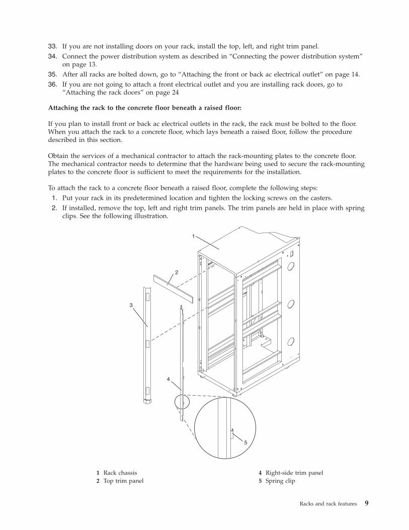
33. If you are not installing doors on your rack, install the top, left, and right trim panel.34. Connect the power distribution system as described in “Connecting the power distribution system”
on page 13.35. After all racks are bolted down, go to “Attaching the front or back ac electrical outlet” on page 14.36. If you are not going to attach a front electrical outlet and you are installing rack doors, go to
“Attaching the rack doors” on page 24
Attaching the rack to the concrete floor beneath a raised floor:
If you plan to install front or back ac electrical outlets in the rack, the rack must be bolted to the floor.When you attach the rack to a concrete floor, which lays beneath a raised floor, follow the proceduredescribed in this section.
Obtain the services of a mechanical contractor to attach the rack-mounting plates to the concrete floor.The mechanical contractor needs to determine that the hardware being used to secure the rack-mountingplates to the concrete floor is sufficient to meet the requirements for the installation.
To attach the rack to a concrete floor beneath a raised floor, complete the following steps:1. Put your rack in its predetermined location and tighten the locking screws on the casters.2. If installed, remove the top, left and right trim panels. The trim panels are held in place with spring
clips. See the following illustration.
1 Rack chassis 4 Right-side trim panel2 Top trim panel 5 Spring clip
Racks and rack features 9

3 Left-side trim panel
3. If installed, remove the front and rear doors. For instructions, see “Attaching the rack doors” onpage 24. After the rack doors have been removed, go to the next step.
4. Locate the hardware mounting kit and the two mounting plates. Refer to the following illustrationwhen reviewing the contents of the hardware mounting kit. The hardware mounting kit contains thefollowing items:v Four rack-mounting boltsv Four thin washersv Eight plastic isolator bushingsv Four thick washersv Four spacers
5. If you are installing an ac-powered rack, temporarily install the lower plastic isolator bushings tohelp you locate the rack-mounting plate. After the mounting plate has been correctly located, removethe lower plastic isolator bushings.
1 Rack chassis 7 Jam nut2 Rack-mounting bolt 8 Leveling foot3 Thin washer 9 Lower plastic isolator bushing (used
only on dc powered systems)4 Top plastic isolator bushing ac Typical leveling foot installation for
an ac-powered rack5 Thick washer dc Typical leveling foot installation for
an dc-powered rack
Figure 8. Removing the trim panels
Figure 9. Installing the ac power-mounting plates
10 Power Systems: Racks and rack features

6 Spacer
6. Position the two mounting plates in the approximate mounting location under the rack.7. Create a rack-mounting bolt assembly by adding the following items, in the order listed, to each
rack-mounting bolt.a. Thin washerb. Top plastic isolator bushingc. Thick flat washerd. Spacer
8. Insert a rack-mounting bolt assembly through each of the leveling feet.9. Reposition the rack-mounting plates under the four rack-mounting bolts so that the mounting bolts
are centered directly over the threaded bolt holes.10. Turn the rack-mounting bolts four complete turns into the mounting plate's threaded bolt holes.11. Mark the raised-floor panel around the edges of front and rear rack-mounting plates.12. Mark the plate bolt-down holes that are accessible through the opening in the rear of the rack.13. Remove the rack-mounting bolt assemblies.14. If you are installing an ac-powered rack, remove the bottom isolator bushing from each of the
leveling feet.15. Remove the rack-mounting plates from the marked locations.16. Loosen each of the locking screws on the casters.17. Move the rack so that it is clear of both areas that were marked on the floor for the rack-mounting
plate locations.18. Reposition the mounting plates within the marked areas.19. Mark the raised-floor panel at the center of each hole in the rack-mounting plates (including the
tapped holes).20. Remove the two rack-mounting plates from the marked locations on the raised floor panel.21. Drill two clearance holes on each end of each rack-mounting plate. The drilled holes should be
approximately 1-inch deep. This depth will accommodate any rack-mounting bolt extending past therack-mounting plate when securing the rack to the rack-mounting plate.
22. For each rack-mounting plate, select at least two suitable hole locations. Select the hole locations asclose to the threaded hole areas as possible. Be sure the hole locations selected at the back of the rackare accessible.
23. Drill pass-through holes in the raised-floor panel. The pass-through holes allow the anchor bolts tobe inserted into the rack-mounting plate and pass through the raised floor panel to the concretefloor.
Note: You must use a minimum of two anchor bolts for each rack-mounting plate to securely attachthe rack-mounting plate through the raised-floor panel to the concrete floor. Because some of theholes in each rack-mounting plate may align with concrete reinforcement rods imbedded in theconcrete, some of the rack-mounting plate holes might not be usable.
24. Transfer the locations of the anchor bolt holes (exclude the clearance holes drilled for therack-mounting bolts) from the raised-floor panel to the concrete floor directly beneath, and mark thehole locations on the concrete floor.
25. Drill holes in the concrete floor to secure the anchor bolts.26. Position the raised-floor panel back into position over the anchor bolt holes.27. Position the front stabilizer bracket within the marked area on the raised-floor panel.28. Using your anchor bolts, secure the front stabilizer brackets on top of the raised floor and through to
the concrete floor.29. Position the rear stabilizer brackets within the marked area on the raised-floor panel.
Racks and rack features 11

1 Rack-mounting bolt 7 Leveling foot2 Thin washer 8 Lower plastic isolator bushing (used
only on dc-powered systems)3 Top plastic isolator bushing 9 Stabilizer brackets4 Thick washer 10 Threaded hole (used to secure the
rack to mounting plate.)5 Spacer 11 Anchor bolt hole6 Jam nut 12 Traced pattern (pattern to be traced
onto the floor using the mountingplate as a template)
30. Using your anchor bolts, secure the back stabilizer bracket on top of the raised floor and through tothe concrete floor.
31. Replace all raised-floor panels that may have been removed when aligning and securing the anchorbolts to the concrete floor.
32. Align the rack over the front and rear stabilizer brackets.33. Insert each of the bolt assemblies through a leveling foot.34. Align the rack-mounting bolts with the threaded holes in each stabilizer bracket. Turn each bolt three
to four rotations.35. Tighten the locking screw on each caster.36. Adjust the leveling feet downward as needed until the rack is level. When the rack is level, tighten
the jam nuts against the base of the rack.37. If you have multiple racks that are connected as a suite (bolted to each other), go to “Connecting
multiple racks with rack-to-rack attachment kit” on page 33. Otherwise, torque the four bolts to 54 -67 newton-meters (40 - 50 foot-pounds).
38. If you are not installing doors on your rack, install the top, left, and right trim panel.
Figure 10. Securing the rack to the floor
12 Power Systems: Racks and rack features

39. Connect the power distribution system. For instructions, see “Connecting the power distributionsystem.”
40. After the rack is bolted down and you are going to attach a front electrical outlet, go to “Attachingthe front or back ac electrical outlet” on page 14.
41. If you are not going to attach a front electrical outlet and you are installing rack doors, go to“Attaching the rack doors” on page 24.
Connecting the power distribution system:
You can use a power distribution system to monitor the individual power loads of the devices that areplugged into it. Use the procedure in this section to connect this system.
To connect a power distribution unit, see “Power distribution unit” on page 39.
Checking the ac outlets:
To help ensure safety and reliable operation, you should check the ac outlets. Use the procedure in thissection to perform this task.
Before you begin, ensure that you have a multimeter to check voltages and an appropriately approvedground-impedance tester to test the grounding resistances.
Note: Use only an appropriately approved ground-impedance tester to test the grounding resistances. Donot use a multimeter to measure grounding resistance.
Before plugging the rack into the ac power source, complete the following checks on the ac power source:1. Turn off the branch circuit breaker for the ac power outlet that the rack will plug into. To the circuit
breaker switch, attach tag S229-0237, which reads Do Not Operate.
Note: All measurements are made with the receptacle faceplate in the usual installed position.2. Some receptacles are enclosed in metal housings. For this type of receptacle, complete the following
steps:a. Using a multimeter, check for less than 1 volt from the receptacle case to any grounded metal
structure in the building, such as a raised-floor metal structure, water pipe, building steel, orsimilar structure.
b. Using a multimeter, check for less than 1 volt from the receptacle ground pin to a grounded pointin the building.
Note: If the receptacle case or faceplate is painted, be sure the probe tip penetrates the paint andmakes good electrical contact with the metal.
c. Using a multimeter, check the resistance from the receptacle ground pin to the receptacle case.Check resistance from the ground pin to the building ground. The readings should be less than 1.0ohm, which indicates the presence of a continuous grounding conductor.
3. If any of the checks made in step 2 are not correct, remove the power from the branch circuit andmake the wiring corrections. Recheck the receptacle after the wiring is corrected.
4. Using a ground-impedance tester, check for infinite resistance between the ground pin of thereceptacle and each of the phase pins. This is a check for a wiring short to ground or a wiringreversal.
5. Using a ground-impedance tester, check for infinite resistance between the phase pins. This is a checkfor a wiring short.
6. Turn on the branch circuit breaker.7. Using a multimeter, measure for the appropriate voltages between phases. If no voltage is present on
the receptacle case or grounded pin, the receptacle is safe to touch.
Racks and rack features 13

8. Using a multimeter, verify that the voltage at the ac outlet is correct.
Attaching the front or back ac electrical outlet:
If you need to attach an ac outlet, you can use the procedure in this section to perform this task.
Attention: The front and rear ac outlet-mounting plates mount through the same mounting holes in thatsecure the stabilizer brackets to the rack chassis. Therefore, if the rack must be bolted to the floor, thestabilizer brackets must be removed.
Install the ac outlet-mounting plates only after the rack has been bolted to the floor and the stabilizerbrackets have been removed.
The following items are installed at the customer's site:v The ac outlet-mounting plates for installing customer-supplied ac electrical outlets on the front or rear
of the rack. The ac outlet-mounting place provides the mounting location for an ac electrical outlet.v The brass ground lug for an electrostatic discharge (ESD) connection.
Note: The customer is responsible for providing both the outlets and the power cables that attach to thepower source. The customer is also responsible for connecting the ac outlet correctly. These items are notfield-replaceable units (FRUs).
Installing the ac outlet-mounting plates with ac outlets:
If you choose to install ac mounting plates, you can follow the procedure detailed in this section toperform this task. This section also includes illustrations of the related hardware components and showshow these components relate to each other.
If you do not want ac outlets installed on the rack, go to “Installing the ac outlet-mounting plate withoutac outlets” on page 17.
If you want ac outlets installed on the front or rear ac outlet-mounting plate, complete the followingsteps:1. Determine the number of ac outlets that you are installing.2. Confirm with your contractor that the number and location of ac outlets to be installed are correct.3. Remove the blank filler plates from the ac outlet-mounting plates for the number of ac outlets being
installed.4. Install the ac outlets on the ac outlet-mounting plate.5. Install the ground lug in the ac outlet-mounting plate using only one nut, as shown in the following
illustration.6. Securely tighten the one nut on the ground lug.7. Locate the Y-shaped ground cable supplied with the mounting plate.
Note: The remaining steps can be used to install ac outlets on the front or the rear of the rack.8. Place the star washer onto the ground lug of the front ac outlet-mounting plate.9. Place the lug on the long end of the ground cable onto the ground lug.
10. Place a ground lug nut onto the ground lug and securely tighten it.11. Position the front ac outlet-mounting plate onto the rack frame with the ground lug fully inserted
through the mounting holes in the rack.12. Route the cable under the rack.13. Place the star washer onto the ground lug of the rear ac outlet-mounting plate.14. Place the lug on the short end of the ground cable onto the ground lug.
14 Power Systems: Racks and rack features

15. Place a ground lug nut onto the ground lug and securely tighten it.
1 Ground cable lug 7 Ground lug2 Star washer 8 Ground connector (short end of
ground cable)3 Front of rack 9 "Y" end of ground cable4 Power cable from the power source 10 Ground lug nut (quantity 2)5 Mounting plate 11 Long end of ground cable6 Long end of ground cable 12 Ground lug nut (quantity 2)
16. Position the rear ac outlet-mounting plate onto the rack frame with the ground lug fully insertedthrough the mounting holes in the rack.
17. Install the front ac outlet-mounting plate screws (stabilizer mounting screws) into the mounting plateand through the mounting holes in the rack. Securely tighten the screws.
1 Front or rear of rack (as applicable) 4 Mounting plate
Figure 11. Installing the ground lug
Racks and rack features 15
2 Power cable from power source 5 Allen wrench3 Button-head screw 6 Long end of ground cable
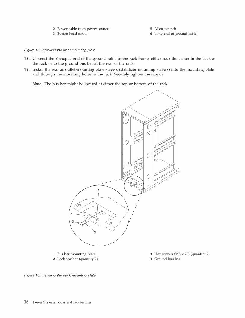
18. Connect the Y-shaped end of the ground cable to the rack frame, either near the center in the back ofthe rack or to the ground bus bar at the rear of the rack.
19. Install the rear ac outlet-mounting plate screws (stabilizer mounting screws) into the mounting plateand through the mounting holes in the rack. Securely tighten the screws.
Note: The bus bar might be located at either the top or bottom of the rack.
1 Bus bar mounting plate 3 Hex screws (M5 x 20) (quantity 2)2 Lock washer (quantity 2) 4 Ground bus bar
Figure 12. Installing the front mounting plate
Figure 13. Installing the back mounting plate
16 Power Systems: Racks and rack features

Installing the ac outlet-mounting plate without ac outlets:
If you choose to install an outlet plate without the outlets, use the procedure in this section to performthis task.
If you do not want any ac outlets installed on the front or rear ac outlet-mounting plate, perform only“Attaching the rack to the concrete floor beneath a raised floor” on page 9 through “Connecting thepower distribution system” on page 13.
For instructions to install front or rear ac outlet-mounting plates, see “Installing the ac outlet-mountingplates with ac outlets” on page 14.
Connecting a dc power source:
Some rack models (such as the 7014-T00) can support a dc power configuration for systems that requiredc power. If you decide to connect a dc power source to the rack, you can use the procedure in thissection to perform this task. This section also includes illustrations of the related hardware componentsand shows how these components relate to each other.
Note: The customer is responsible for providing and connecting the -48 V dc power source and -48 V dcpower return cables from the customer's source -48 V dc to the bus bars in the power distribution panel.The customer is also responsible for connecting the ground cable to the rack frame. This procedureprovides information about accessing the power distribution panel.1. Remove the six mounting screws from the top cover of the dc power distribution panel and remove
the top cover.2. If they are installed, remove the four screws from the cable channel cover.3. Remove the cable channel cover.
1 Cable channel cover retaining screw 5 Shield2 Cable channel cover 6 Power distribution panel3 Power distribution panel top cover
retaining screws
Racks and rack features 17

4 Power distribution panel top cover
4. Remove the -48 V dc bus bar shield from the power distribution panel.Attention: The bus bar shield must be correctly reinstalled over the -48 V dc return bus bars toprotect against injury while servicing the power distribution panel.
5. Ensure that the following steps are performed when connecting the dc power source.a. At -48 V dc power source, turn off any -48 V dc power sources that will be connected to the
power distribution panel.b. After the -48 V dc power sources are turned off, be sure there is a tag or label over the power
source switches or fuses (lock-out/tag-out) to indicate that the power source is turned offintentionally.
Note: Ensure that any oxidation on the copper bus bars is removed.c. If this is a raised-floor installation and you are working at the back of the rack, route the power
cables up the rack's right side.d. Ensure that the external -48 V dc power cable is connected correctly to the -48 V dc bus bar.e. Ensure that the external -48 V dc return cable is routed correctly and installed on the return bus
bar.
1 -48 V dc power cable and return power cable2 Power distribution panel3 Front of rack4 -48 V dc power cable and return power cable
Figure 14. Removing the cable channel cover
Figure 15. Routing the power cables
18 Power Systems: Racks and rack features

1 Front of power distribution panel 6 (B) Return (-) power cable2 (A) -48 V dc (-) bus bar 7 (B) -48 V dc (-) power cable3 (A) -48 V dc (-) power cable 8 (B) Return (-) bus bar4 (A) Return (-) bus bar 9 (B) -48 V dc (-) bus bar5 (A) Return (-) power cable
f. If you want to install a power status alarm, connect the alarm cable to the terminal board on theback cover of the dc power distribution panel.
Note: Ensure that you remove the oxidation on the copper bus bars.g. Ensure that the power-source ground cable is routed correctly and connects the power-source
ground cable to the copper bar at the lower-back or upper-back center of the rack.h. If the rack is on a raised floor, attach the -48 V dc power source cables to the rear of the rack with
cable-restraint straps.
Figure 16. Return bus bar
Racks and rack features 19

1 Rear view of rack (dc)2 Power cable, power return cable, and ground3 Ground cable (Install at either top or bottom of the rack)
6. Reinstall the -48 V dc bus bar shield.7. Reinstall the top cover on the dc power distribution panel.8. Reinstall the cable channel cover.
1 Cable channel cover
Figure 17. Cable locations
20 Power Systems: Racks and rack features

2 Terminal block (both sides)3 Power distribution panel4 Front of rack
Removing and replacing 7014-T00 or 7014-T42 side panelsLearn how to remove and replace a side panel on a rack. Use the procedures in this section to performthis task.
Removing a 7014-T00 or 7014-T42 side panel:
Use the procedure in this section to remove a side panel on a rack.
To remove a side panel, complete the following steps:1. Unlock the side panels by pressing down on both locking latches to release the latches.
Note: If your rack uses a ruggedized kit, you must remove the securing screw to allow each sidepanel to be removed. See “Releasing the side panel with a ruggedized kit” on page 32.
2. Tilt the top of the side panel slightly toward you.3. Lift the side panel away from the ridge on the bottom of the rack.4. Repeat this procedure for the other side panel.
Figure 18. Reinstalling the cable channel cover
Figure 19. Removing the side panel
Racks and rack features 21

Replacing a 7014-T00 or 7014-T42 side panel:
Use the procedure in this section to replace a side panel on a rack.
To replace a side panel, complete the following steps:1. Tilt the top of the side panel slightly toward you.2. Place the bottom of the side panel onto the ridge on the bottom of the rack.
3. Slide the top of the side panel into place and close the locking latches.
Note: If your rack uses ruggedized kit, you must install a securing screw into each side panel thatwas installed. See “Ruggedized kit” on page 30.
Removing and replacing 7014-T00 or 7014-T42 trim panelsRacks that are installed with multiple processor drawer systems can use front trim panels instead ofdoors. For racks that use trim panels, a reduced-interference panel type must be installed when certainexpansion unit models are present. Use the procedures in this section to remove the existing trim panelsfrom the rack and replace them with the reduced-interference panel type.
Removing the 7014-T00 or 7014-T42 trim panels:
For racks that use trim panels instead of doors, a reduced-interference panel type must be installed whencertain expansion unit models are present. Use the procedure in this section to remove the trim panels.
To remove the existing rack trim panels, complete the following steps:
Figure 20. Replacing the side panel
22 Power Systems: Racks and rack features

1. Place both hands on the center of the right side trim panel.
2. Squeeze inward firmly with your fingertips to release the spring clips that hold the panel in place.3. Rotate your hands in slightly until the panel is disengaged.4. Lift the panel out and set it aside.5. Repeat this procedure to remove the left side trim panel.
Replacing the 7014-T00 or 7014-T42 trim panels:
For racks that use trim panels instead of doors, a reduced-interference panel type must be installed whencertain expansion unit models are present. Use the procedure in this section to replace the trim panels.
To install the trim panels, complete the following steps:
Figure 21. Removing the rack trim panel
Racks and rack features 23

1. Align the bottom plate (A) of the right side trim panel to the bottom of the rack.
2. Align the top of the trim panel (B) and squeeze slightly with your fingertips.3. After the trim panel is in the correct location, release the pressure to allow the spring clips to hold the
panel in place.4. Repeat this procedure to install the left side trim panel.
Attaching the rack doorsLearn how to attach the rack doors. Use this procedure to perform this task.
Depending on the model of the rack, the front door of a rack might be an optional feature. If your systemalready has the front door installed, or does not have a front door to install, skip this step.
Figure 22. Installing the rack trim panel
24 Power Systems: Racks and rack features

Attaching a high-perforation front door:
You might need to attach a front door to the rack. Use the procedure in this section to perform this task.
To install the high-perforation front door, complete the following steps:1. Read the “Rack safety notices” on page 26.2. Remove the top, left, and right trim panels. For details about removing the left and right trim panels
from a 7014-T00 or 7014-T42 rack, see “Removing and replacing 7014-T00 or 7014-T42 trim panels” onpage 22.
Figure 23. Attaching the rack door
Racks and rack features 25

1 Rack chassis 4 Right-side trim panel2 Top trim panel 5 Spring clip3 Left-side trim panel
3. Install the door latch on the right and the door hinges on the left.4. For a high-perforation front door, align the door over the rack hinge, then move up the hinge pin on
the door, and lower the hinge pin into the hinge.5. Adjust the latch so the door latches securely.
Rack safety notices:
You need to read the rack safety notices before installing equipment.
Before installing a rack, rack features, or a system or expansion unit into a rack, read the following safetyinformation.
Attention: If you are installing equipment into a non-IBM rack, the rack must comply with theElectronics Industries Association (EIA) 310D specifications. If you do not have a rail kit designed for theequipment in the non-IBM rack, do not install the equipment into the rack as damage to the equipmentor personal injury could occur.
Figure 24. Removing the trim panels
26 Power Systems: Racks and rack features

DANGER
Observe the following precautions when working on or around your IT rack system:
v Heavy equipment–personal injury or equipment damage might result if mishandled.
v Always lower the leveling pads on the rack cabinet.
v Always install stabilizer brackets on the rack cabinet.
v To avoid hazardous conditions due to uneven mechanical loading, always install the heaviestdevices in the bottom of the rack cabinet. Always install servers and optional devices startingfrom the bottom of the rack cabinet.
v Rack-mounted devices are not to be used as shelves or work spaces. Do not place objects on topof rack-mounted devices.
v Each rack cabinet might have more than one power cord. Be sure to disconnect all power cords inthe rack cabinet when directed to disconnect power during servicing.
v Connect all devices installed in a rack cabinet to power devices installed in the same rackcabinet. Do not plug a power cord from a device installed in one rack cabinet into a powerdevice installed in a different rack cabinet.
v An electrical outlet that is not correctly wired could place hazardous voltage on the metal parts ofthe system or the devices that attach to the system. It is the responsibility of the customer toensure that the outlet is correctly wired and grounded to prevent an electrical shock.
CAUTION
v Do not install a unit in a rack where the internal rack ambient temperatures will exceed themanufacturer's recommended ambient temperature for all your rack-mounted devices.
v Do not install a unit in a rack where the air flow is compromised. Ensure that air flow is notblocked or reduced on any side, front, or back of a unit used for air flow through the unit.
v Consideration should be given to the connection of the equipment to the supply circuit so thatoverloading of the circuits does not compromise the supply wiring or overcurrent protection. Toprovide the correct power connection to a rack, refer to the rating labels located on theequipment in the rack to determine the total power requirement of the supply circuit.
v (For sliding drawers.) Do not pull out or install any drawer or feature if the rack stabilizer bracketsare not attached to the rack. Do not pull out more than one drawer at a time. The rack mightbecome unstable if you pull out more than one drawer at a time.
v (For fixed drawers.) This drawer is a fixed drawer and must not be moved for servicing unlessspecified by the manufacturer. Attempting to move the drawer partially or completely out of therack might cause the rack to become unstable or cause the drawer to fall out of the rack.
(R001)
Lift precautions:
Racks and rack features 27
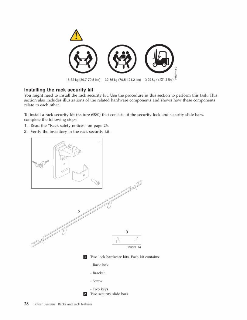
Installing the rack security kitYou might need to install the rack security kit. Use the procedure in this section to perform this task. Thissection also includes illustrations of the related hardware components and shows how these componentsrelate to each other.
To install a rack security kit (feature 6580) that consists of the security lock and security slide bars,complete the following steps:1. Read the “Rack safety notices” on page 26.2. Verify the inventory in the rack security kit.
�1� Two lock hardware kits. Each kit contains:
- Rack lock
- Bracket
- Screw
- Two keys�2� Two security slide bars
28 Power Systems: Racks and rack features

�3� Two locked/unlocked stickers
3. Remove the existing door latch.a. Open the front rack door.b. On the inside of the door, remove the screw (4) in Figure 26 that secures the lock to the rack door.
c. Remove the bracket (5).d. From the outside of the door, remove the door latch (6).
Note: If the rack is equipped with the ruggedized kit, remove the jam nut and hex nut from theexisting door latch and reinstall both nuts on the new door lock latch.
4. Install the locking latch.a. Insert the keyed rack lock into the latch slot on the front of the door (6) in Figure 26.b. Secure the lock by attaching the lock bracket (5) with the screw (4), on the inside of the door.
5. Repeat steps 3 and 4 to install the second lock on the back rack door.6. Install a security slide bar on the right side of the rack.
Note: Each slide bar rail has two long tabs on the bottom of the rail. The slide bar rails are identicaland can be installed on either the right or left side cover panel.a. Unlatch right-side cover panel and lean the panel back so that you can access the top of the panel.b. With the flat side of the slide bar rail (7) in Figure 27 on page 30, facing the inside of the cover
panel (8), insert the two tabs (9), on the slide bar rail into the two vertical support channels (10)on the side cover panel.
Figure 25. Rack security kit inventory
Figure 26. Removing the existing door latch
Racks and rack features 29

Note: When installed correctly, the slide rail moves from front to back.
c. Reinstall the side panel cover on to the rack.d. Lock the side panel covers by sliding the bars to the front of the rack.e. Place a locked/unlocked sticker on the inside of the cover panel so that when the slide bar is in
the locked position, the tab is over the locked symbol (11), as shown in Figure 28, and over theunlocked symbol (12), when the slide bar is unlocked.
f. Repeat the procedure for the left side of the rack.
Ruggedized kitYou might need to remove or replace a part in the ruggedized kit. This section includes procedures sothat you can perform these tasks.
Figure 27. Installing a security slide bar
Figure 28. Placing the locked/unlocked sticker on the cover panel
30 Power Systems: Racks and rack features

The ruggedized kit, feature code 6080, should be ordered at the same time the rack is ordered. Theruggedized kit brackets are installed at the manufacturer.
Note: If you are installing a rack with the ruggedized kit and need to secure the rack to the floor, see“Installing the rack” on page 1.
The following illustration highlights the contents of the kit and the approximate location of each bracketand hinges in the event that you need to uninstall and reinstall a part.
�1� Rack �9� Brace hinges�2� Spacer �10� Brace�3� Brace hinge �11� Side-door securing screw mount�4� Hinge pivot studs �12� Spacer�5� Brace latch bracket �13� Screw�6� Spacer �14� Washer�7� Screw �15� Side door securing screw�8� Brace thumbscrew
Releasing the ruggedized brace:
You might need to release the ruggedized brace. Use the procedure in this section to perform this task.
To access the back of a system that is installed in a rack with a ruggedized kit, complete the followingsteps to release the ruggedized brace:1. Remove the brace thumbscrew (8).
Figure 29. Ruggedized kit parts
Racks and rack features 31
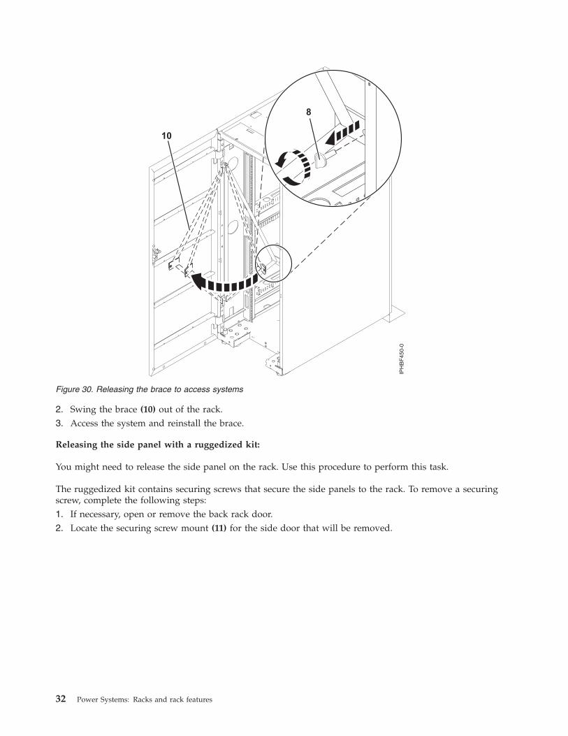
2. Swing the brace (10) out of the rack.3. Access the system and reinstall the brace.
Releasing the side panel with a ruggedized kit:
You might need to release the side panel on the rack. Use this procedure to perform this task.
The ruggedized kit contains securing screws that secure the side panels to the rack. To remove a securingscrew, complete the following steps:1. If necessary, open or remove the back rack door.2. Locate the securing screw mount (11) for the side door that will be removed.
Figure 30. Releasing the brace to access systems
32 Power Systems: Racks and rack features

3. Using a screwdriver, remove the securing screw (15) and washer (14) from the side panel. To removethe side panel, see “Removing and replacing 7014-T00 or 7014-T42 side panels” on page 21.
Connecting multiple racks with rack-to-rack attachment kitYou might need to connect multiple racks together. Use the procedure in this section to perform this task.
This topic describes how to connect multiple racks to each other using a rack-to-rack attachment kit. Todo this, you will need the rack-to-rack attachment kit (feature 7840).
To connect multiple racks with the rack-to-rack attachment kit, complete the following steps:1. Read the “Rack safety notices” on page 26.2. If they are installed, remove the side panels from each rack. Remove side panels only from the sides
that will be attached to each other by completing the following steps:a. Lift up the two panel-release tabs.b. Pull the panel up and away from the rack chassis. This motion will release the panel from the
two lower J brackets.c. Store the side panels.
3. Remove the two Z brackets and the two J brackets. These brackets are used to hang the side panels.
Figure 31. Removing the securing screws on the side panel
Racks and rack features 33

4. Install the first two standoffs in the upper-left and lower-right corners of the first rack as shown inFigure 32.
5. Install the second two standoffs in the upper-left and lower-right corners of the second rack asshown in Figure 32.
6. Attach the long foam as shown in Figure 32. For a model T42 rack, join the short foam to the end ofthe long foam, and adhere it to the frame length of the rack.
7. Position the racks together.8. Align the standoff holes. You might need to adjust the leveling feet to do this.
Figure 32. Removing the side panels, Z and J brackets, and installing standoffs and long foam to connect multipleracks
Figure 33. Location of foam strips (top view)
34 Power Systems: Racks and rack features
9. Install a screw and washer into all four positions, but do not tighten.10. After all racks are bolted together, level the racks.11. Tighten all four screws.12. Snap on the trim pieces that go between the front and back racks.13. Snap on the trim piece that goes on top and between the racks.14. Install rack filler panels to cover the open areas at the front of the racks. All the gaps in the front of
the rack must also be sealed, including the gaps between equipment. This step ensures that properairflow within the rack is maintained.
15. Connect the cables that go between the racks.16. If you are installing tip plates, go to step 5 in “Installing the rack” on page 1.
Removing and replacing the rack top coverYou might need to remove or replace the rack top cover. User these procedures to perform these tasks.
Removing the rack top cover:
You might need to remove the rack top cover. Use this procedure to perform this task.
Note: A 10 mm box socket with an extension bar is required to remove the screws from the top cover.Other tools might cause the screw heads to become rounded and unremovable.
To remove the rack cover from the rack, complete the following steps:1. Remove the front door.
Note: If the rack is locked, unlock the doors. Then unlock the side panels by removing the lockingbars from both sides of the top rear of the rack. Slide the locking bars out from the rack at the top ofeach side of the rack from the rear. The locking bars can be removed from each side of the front of therack if the rack space in the locking bars area is open and the bars are easily accessible.
2. Remove the top, left, and right trim panels.3. Remove the side panels. For more information, see “Removing and replacing 7014-T00 or 7014-T42
side panels” on page 21.4. Remove one screw from the right side of the top cover and one screw from the left side of the top
cover. Do for both front and rear covers.5. Locate the front (A) and back (C) rack braces that were provided in the shipping container. Fasten
each rack brace at the top of the front and rear of the rack, just below the top cover.6. Use the four screws (B) that were removed from the top cover to secure each rack brace to the rack,
as shown in Figure 34 on page 36.
Racks and rack features 35

A Front rack braceB Retaining screws (2 screws for each brace)C Rear rack brace
7. Remove the remaining six screws from the left and right sides of the top cover (D).
Figure 34. Securing the rack brace
36 Power Systems: Racks and rack features

D Top coverE Cable access coverF Side cover (quantity 2)
G EIA label
8. Lift off the top cover.
Replacing the rack top cover:
You might need to replace the rack top cover. Use this procedure to perform this task.
Note: A 10 mm box socket with an extension bar is required to replace the screws into the rack top cover.Other tools might cause the screw heads to become rounded and unable to be removed again.
To replace the rack top cover onto the rack, complete the following steps:1. Position the rack top cover (D) on the rack.2. Install the six screws at the left and right sides of the rack top cover.
Figure 35. Removing the top cover
Racks and rack features 37

D Top coverE Cable access coverF Side cover (quantity 2)
G EIA label
Note: A 10 mm box socket with an extension bar is required to replace the screws into the rack topcover. Other tools might cause the screw heads to become rounded and unable to be removed again.
3. Remove the rack braces (A) and (C) by unfastening them at the top of the rack, just below the topcover. Remove the braces at the front and rear of the rack.
Figure 36. Removing the top cover
38 Power Systems: Racks and rack features

A Front rack braceB Retaining screws (quantity 2 for each brace)C Rear rack brace
4. Install the screws (B) you removed from the rack braces at the right and left side of the top cover.Install the screws for both the front and rear of the rack.
5. Install rack filler panels to cover open areas at the front of the rack. Seal all gaps in the front of therack, including the gaps between pieces of equipment. This step ensures that proper airflow withinthe rack is maintained.
Power distribution unitThe power distribution unit (PDU) or power distribution unit plus (PDU+) can be installed in the7014-T00 and 7014-T42 racks. It allows you to monitor the individual power loads of the devices that areplugged into it.
Installing the PDU or PDU+ in the side of a rack:
Learn how to install the power distribution unit (PDU) or power distribution unit plus (PDU+) verticallyin the side of a rack.
Tip: Removing the rack doors and side panels might make installation easier.
To install the PDU model in a single EIA vertical mounting space in the side of the rack, complete thefollowing steps:1. Read the “Rack safety notices” on page 26.2. Choose one of the following options to install your PDU model:
v To install the PDU, go to step 5 on page 40.v To install the PDU+, continue with step 3 on page 40.
Figure 37. Removing the top cover
Racks and rack features 39

3. Align the vertical-mounting brackets (A) to the front of the PDU+. Make sure that you attach thebrackets so that the power outlets face the rear of the rack.
4. Attach the brackets (A) to the PDU+ with two M3x5 screws (B) per bracket. Use screws that wereprovided with the rack mounting kit.
5. Attach nut clips (A) to the four locations on the rack mounting flanges where the PDU model will beattached. Use nut clips that were provided with the rack mounting kit. See the following figure.
6. Align the PDU model with the opening in the side of the rack. Then, while holding the PDU modelin place, attach the brackets to the nut clips in the rack mounting flanges with four M5 screws (A) asshown in the following figure. Use screws that were provided with the rack mounting kit.
Figure 38. Aligning the vertical-mounting brackets to the front of the PDU+
Figure 39. Attaching nut clips to the rack mounting flanges
40 Power Systems: Racks and rack features

Attention: You must disconnect the main input power before connecting or disconnecting the inputpower cord from the PDU model.
7. If the PDU model was provided with a detached power cord, connect the power cord now. Align theconnector on the power cord (A) that was provided with the PDU model with the connector on thefront of the unit (A), turning as necessary for key alignment. Then, turn the connector twist-lock (B)clockwise until it locks into place.
8. Route the power cord from the PDU model toward the rack side braces. Then, route the power cordalong a side brace toward the rear of the rack and secure the power cord with the cable straps thatare provided with the PDU model.
Figure 40. Aligning the PDU+ with the opening in the side of the rack
Figure 41. Aligning the connector on the power cord with the PDU model
Racks and rack features 41

9. Route the power cord toward a dedicated power source. Use the provided cable straps to secure thepower cord along the way. Use the openings in the rack, if the power cord must exit the rack toconnect to a power source.Attention: To prevent damage to a power device and other connected devices, always connect thepower device to an authorized power source for that device.
10. Connect the power cord to a properly wired and grounded dedicated power source. Then, connectthe servers or rack PDUs in the rack to the power outlets on the PDU model.
11. Route all of the other power cables neatly, and secure the power cables with cable straps.Related concepts:“Setting up power monitoring using the PDU+” on page 45You can monitor the power status for any device that is connected to the power distribution unit plus(PDU+), either manually or remotely, through the PDU+ web interface.
Installing the PDU or PDU+ horizontally in a rack:
Learn how to install the power distribution unit (PDU) or power distribution unit plus (PDU+)horizontally in the side of a rack.
Tip: Removing the rack doors and side panels might make installation easier.
To install the PDU model in a single EIA horizontal mounting space in the rack, complete the followingsteps:1. Read the “Rack safety notices” on page 26.2. Choose one of the following options to install your PDU model:
v To install the PDU, go to step 5.v To install the PDU+, continue with step 3.
3. Align the vertical-mounting brackets (A) to the front of the PDU+ as shown in the following figure.Make sure that you attach the brackets so that the power outlets face the rear of the rack.
4. Attach the brackets (A) to the PDU+ with two M3x5 screws (B) per bracket. Use screws that wereprovided with the rack mounting kit.
5. Align the long mounting brackets (A) with the holes in the rear of the PDU model, and attach thebrackets to the PDU model with two M3 pan-head screws (B) with captive lock washers per bracket.
Figure 42. Aligning the vertical-mounting brackets to the front of the PDU+
42 Power Systems: Racks and rack features
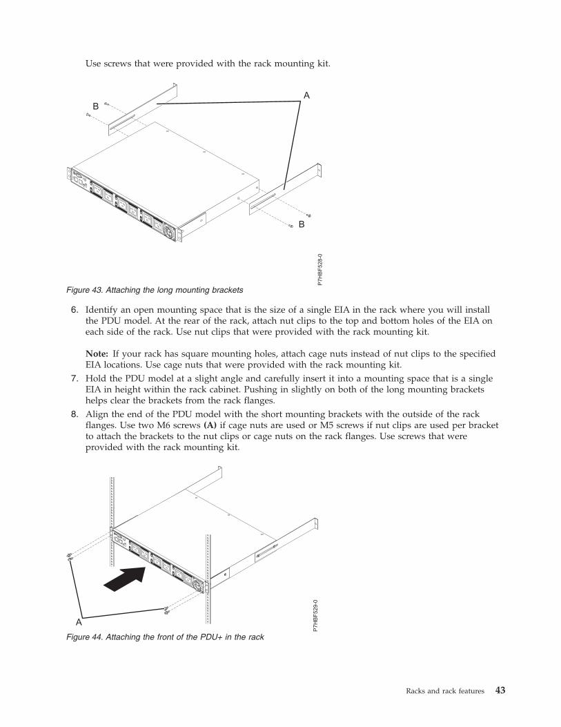
Use screws that were provided with the rack mounting kit.
6. Identify an open mounting space that is the size of a single EIA in the rack where you will installthe PDU model. At the rear of the rack, attach nut clips to the top and bottom holes of the EIA oneach side of the rack. Use nut clips that were provided with the rack mounting kit.
Note: If your rack has square mounting holes, attach cage nuts instead of nut clips to the specifiedEIA locations. Use cage nuts that were provided with the rack mounting kit.
7. Hold the PDU model at a slight angle and carefully insert it into a mounting space that is a singleEIA in height within the rack cabinet. Pushing in slightly on both of the long mounting bracketshelps clear the brackets from the rack flanges.
8. Align the end of the PDU model with the short mounting brackets with the outside of the rackflanges. Use two M6 screws (A) if cage nuts are used or M5 screws if nut clips are used per bracketto attach the brackets to the nut clips or cage nuts on the rack flanges. Use screws that wereprovided with the rack mounting kit.
Figure 43. Attaching the long mounting brackets
Figure 44. Attaching the front of the PDU+ in the rack
Racks and rack features 43

9. Secure the long mounting brackets and the blank filler panel (A) to the rack cabinet by completingthe following steps:
a. Adjust the long mounting brackets (A) to fit the depth of the rack cabinet.b. Tighten the M3 pan-head screws (D) that secure the long mounting brackets to the PDU model.c. Make sure that the long mounting brackets are aligned with the inside of the rack flanges.d. Align the blank filler panel (B) on the outside of the rack flanges.e. Attach the filler panel to the rack flanges and then to the long mounting bracket with one M6
screw (C) per bracket. Use screws that were provided with the rack mounting kit.10. If the PDU model was provided with a detached power cord, connect the power cord now. Align the
connector on the power cord (A) that was provided with the PDU model with the connector on thefront of the unit (A), turning as necessary for key alignment. Then, turn the twist-lock (B) on theconnector clockwise until it locks into place.Attention: You must disconnect the main input power before connecting or disconnecting the inputpower cord from the PDU model.
Figure 45. Attaching the brackets and filler panel to the rack
44 Power Systems: Racks and rack features

11. Route the power cord from the PDU model toward the rack side braces. Then, route the power cordalong a side brace toward the back of the rack and secure the power cord with the cable straps thatare provided with the PDU model.
12. Route the power cord toward a dedicated power source. Use the provided cable straps to secure thepower cord along the way. Use the openings in the rack if the power cord must exit the rack toconnect to a power source.Attention: To prevent damage to a power device and other connected devices, always connect thepower device to an authorized power source for that device.
13. Connect the power cord to a properly wired and grounded dedicated power source. Then, you canconnect the servers or rack PDUs in the rack to the power outlets on the PDU model.
14. Route all of the other power cables neatly, and secure the power cables with cable straps.
Setting up power monitoring using the PDU+:
You can monitor the power status for any device that is connected to the power distribution unit plus(PDU+), either manually or remotely, through the PDU+ web interface.
Note: All of the Configuration Utility configuration options are available through the web interface afterthe PDU+ is set up on the local network.Related tasks:“Installing the PDU or PDU+ in the side of a rack” on page 39Learn how to install the power distribution unit (PDU) or power distribution unit plus (PDU+) verticallyin the side of a rack.
Using the IBM DPI Configuration Utility:
Learn how to use the IBM Distributed power interconnect (DPI) Configuration Utility to configure thepower distribution unit plus (PDU+) settings, such as the IP address, network parameters, access controltable, and trap receivers table.
Connecting the console:You can configure the PDU+ by using a workstation or notebook computer that is connected to thePDU+. Connect the DB9-to-RJ-45 cable that is shipped with the PDU+ to the RJ-45 console connector onthe PDU+, and to a RS-232 serial (COM) connector on a workstation or notebook computer.
Using HyperTerminal:
Figure 46. Aligning the connector on the power cord with the PDU model
Racks and rack features 45

HyperTerminal is a terminal program in a Microsoft Windows operating system that enables you toconfigure or control a device using command line parameters. You can configure the PDU+ parametersand its outlets using numeric commands from a keyboard. You can also use Telnet or any other terminalprogram to configure the PDU+ after the IP address is set.
To start HyperTerminal and communicate with the PDU+, complete the following steps:1. Click Start > Programs > Accessories > Communications > HyperTerminal. The Connection
Description window is displayed.2. Type the name for the connection in the Name field and select an icon for the connection.3. Click OK. The Connect To window is displayed.4. In the Connect using field, select the COM port that is connected to the PDU+.5. Click OK. The Properties window is displayed.6. Click Restore Defaults to use the default settings. Make sure that the Bits per second field is 9600
and that the Flow control field is None.7. Click OK.8. Press any key. The Configuration Utility main menu is displayed.9. Type the default password, passw0rd (all lowercase letters with a zero, not O), and press Enter.
10. Enter the menu option that you want. For descriptions of the options, see “Configuration Utilitymenu options.”
Configuration Utility menu options:The following options are shown on the Configuration Utility main menu:
IBM DPI SettingsWhen you select IBM DPI Settings, the IBM DPI Configuration Utility window is displayed withthe following options:
Set the IP Address, Gateway Address and MIB System GroupView and change the IP address, date, time, and MIB system information.
Set IBM DPI Control GroupSet the administrator user name, password, and access protocols.
Set Write Access ManagersSet up a list of users who can access and control the PDU+.
Set Trap ReceiversConfigure remote network management system (NMS) servers to receive traps.
Set Date and TimeAdjust the date and time information for the PDU+.
Set Superuser Name and PasswordSet the user name and password of the administrator who will use a web browser toconfigure the PDU+.
E-mail NotificationSet up a list of users who will be alerted with event messages if an unusual event istriggered on the PDU+ system.
Set Multi-UsersConfigure other user and password logins and the read and write access levels.
Set IBM DPI InformationConfigure the PDU+ logging interval, refresh rate, and custom name fields for the loadgroups.
Settings and Event Log SummaryView all PDU+ configuration settings.
46 Power Systems: Racks and rack features

Reset Configuration to DefaultReset all system settings to their factory default values.
Restart HD-PDURestart the PDU+.
Setting the IP address:
Important: You must set the IP address before you can use the web interface or access the PDU+ in an IPnetwork (LAN/WAN). Contact your system administrator if you do not know the IP address.
To set the IP address, complete the following steps:1. In the Configuration Utility main menu, enter the menu option for IBM DPI Settings.2. Enter the menu option for Set the IP Address, Gateway Address and MIB System Group.
Using the web interface to configure the PDU+:
Learn how to use the web interface to configure and monitor the power distribution unit plus (PDU+)remotely. The PDU+ provides a graphical user interface that you can view from a web browser. Using aweb browser, you can access and monitor the PDU+ power outlets and output devices remotely from aworkstation or notebook computer.
Starting the web interface:To start the web interface, complete the following steps:1. Start a web browser from a workstation or notebook computer, and enter the IP address of the PDU+
in the address field. The Connect to window is displayed.
Note: For more information about setting the IP address of the system, see “Setting the IP address.”2. In the User name field, type USERID (all uppercase letters).3. In the Password field, type passw0rd (all lowercase letters with a zero, not O).4. Click OK. The main status page is displayed.
The main status page displays a graphical representation of the PDU+ power outlets and input status:v The left pane displays the menus and submenus for the PDU+. Click a menu to display the menu
options, expand the menu items, and modify the menu options as required.v The graphic displayed in the right pane shows the status of the outlets, input voltage, output voltage,
frequency, current and power, watt-hour consumption, and cumulative kilowatt hour powerconsumption. If you connect an optional environmental monitored probe, the temperature andhumidity environment conditions are displayed.
Each menu page provides online help to assist you with configuring the PDU+. Click the Help icon atthe top of each page to view the help.
Changing the basic settings:
Use the System menu to configure the PDU+ system parameters such as the superuser name, password,IP address, date, and time.
Changing the superuser name and password:
You can set the user name and password of the administrator who will use a web browser to configurethe PDU+ on the Configuration Utility page.
To change the superuser name and password, complete the following steps:1. From the main status page, in the left navigation pane, click System.
Racks and rack features 47
2. Click Configuration to view and modify the system configuration and superuser user name andpassword.
Identifying the PDU+ and Web/SNMP card:
You can view the PDU+ and Web/SNMP card information on the Identification of Power Managementpage.
To view the power management information of the PDU+ and Web/SNMP card, complete the followingsteps:1. From the main status page, in the left navigation pane, click System.2. Click Identification to view the PDU+ and Web/SNMP card information.
Adding users:
You can add users who can access and control the PDU+ on the Multi-User Configuration page.
To create a list of users who can access and control the PDU+, complete the following steps:1. From the main status page, in the left navigation pane, click System.2. Click Multi-User to add users who can only view the PDU+ status or users who can change the
PDU+ settings.
Changing the date and time:
You can change the date and time of the PDU+ on the Date and Time page.
Important: Changing the PDU+ date and time affects other system settings such as e-mail, traps, andlogs.
To change the date and time, complete the following steps:1. From the main status page, in the left navigation pane, click System.2. Click Date and Time to view and modify the system date and time. You can set the date and time
manually, synchronize it with the computer time, or synchronize it with an NTP server.
Changing event alerts:
You can change event alerts on the SNMP Trap Receivers page.
To configure the PDU+ to send e-mail or SNMP trap alerts to specified users when specific events occur,complete the following steps:1. From the main status page, in the left navigation pane, click System.2. Click Trap Receivers to create a list of users or workstations who will be alerted with an SNMP trap
message. You can specify the IP addresses of up to eight trap receivers, the community information,type of trap, severity of trap, and description of the events that cause the traps.
3. Click Email Notification under System to create a list of up to four users who will be alerted with ane-mail. Use this menu to specify the mail server, user account, DNS, and other information necessaryto set up a mail server for sending mail alerts. Use the Email Receivers Table to add the e-mailaddresses.
Changing the network information:
Use the Network menu to change the network information for the PDU+, for example, the IP address.
48 Power Systems: Racks and rack features
Changing the network configuration:
You can view or change the network configuration on the Network Configuration page.
To view or change the network configuration of the PDU+, complete the following steps:1. From the main status page, in the left navigation pane, click Network.2. Click Configuration to set the PDU+ IP address, gateway address, subnet mask, and Domain Name
System (DNS) address.3. Click Control to configure TCP/IP settings.4. Click Access Control to set access control to prevent unauthorized users from accessing the PDU+.
History and event log summaries:
The Logs menu provides a detailed description of all events and a record of the PDU+ status. Systemadministrators can use this page to analyze problems with network equipment.
Viewing the history log:
You can view the complete history of the PDU+ inputs and outputs on the History Log page.
To view the history of the PDU+, complete the following steps:1. From the main status page, in the left navigation pane, click Logs.2. Click History. Each event log file shows the time, date, and description of all the events occurring on
the PDU+.
Viewing the event log:
You can view the complete record of the PDU+ events on the Event Log page.
To view the complete record of the PDU+ events, complete the following steps:1. From the main status page, in the left navigation pane, click Logs.2. Click Events. Each log file shows a record of the input power and output power of each outlet.
Racks and rack features 49

50 Power Systems: Racks and rack features

Notices
This information was developed for products and services offered in the U.S.A.
The manufacturer may not offer the products, services, or features discussed in this document in othercountries. Consult the manufacturer's representative for information on the products and servicescurrently available in your area. Any reference to the manufacturer's product, program, or service is notintended to state or imply that only that product, program, or service may be used. Any functionallyequivalent product, program, or service that does not infringe any intellectual property right of themanufacturer may be used instead. However, it is the user's responsibility to evaluate and verify theoperation of any product, program, or service.
The manufacturer may have patents or pending patent applications covering subject matter described inthis document. The furnishing of this document does not grant you any license to these patents. You cansend license inquiries, in writing, to the manufacturer.
The following paragraph does not apply to the United Kingdom or any other country where suchprovisions are inconsistent with local law: THIS PUBLICATION IS PROVIDED “AS IS” WITHOUTWARRANTY OF ANY KIND, EITHER EXPRESS OR IMPLIED, INCLUDING, BUT NOT LIMITED TO,THE IMPLIED WARRANTIES OF NON-INFRINGEMENT, MERCHANTABILITY OR FITNESS FOR APARTICULAR PURPOSE. Some states do not allow disclaimer of express or implied warranties in certaintransactions, therefore, this statement may not apply to you.
This information could include technical inaccuracies or typographical errors. Changes are periodicallymade to the information herein; these changes will be incorporated in new editions of the publication.The manufacturer may make improvements and/or changes in the product(s) and/or the program(s)described in this publication at any time without notice.
Any references in this information to websites not owned by the manufacturer are provided forconvenience only and do not in any manner serve as an endorsement of those websites. The materials atthose websites are not part of the materials for this product and use of those websites is at your own risk.
The manufacturer may use or distribute any of the information you supply in any way it believesappropriate without incurring any obligation to you.
Any performance data contained herein was determined in a controlled environment. Therefore, theresults obtained in other operating environments may vary significantly. Some measurements may havebeen made on development-level systems and there is no guarantee that these measurements will be thesame on generally available systems. Furthermore, some measurements may have been estimated throughextrapolation. Actual results may vary. Users of this document should verify the applicable data for theirspecific environment.
Information concerning products not produced by this manufacturer was obtained from the suppliers ofthose products, their published announcements or other publicly available sources. This manufacturer hasnot tested those products and cannot confirm the accuracy of performance, compatibility or any otherclaims related to products not produced by this manufacturer. Questions on the capabilities of productsnot produced by this manufacturer should be addressed to the suppliers of those products.
All statements regarding the manufacturer's future direction or intent are subject to change or withdrawalwithout notice, and represent goals and objectives only.
The manufacturer's prices shown are the manufacturer's suggested retail prices, are current and aresubject to change without notice. Dealer prices may vary.
© Copyright IBM Corp. 2012, 2013 51

This information is for planning purposes only. The information herein is subject to change before theproducts described become available.
This information contains examples of data and reports used in daily business operations. To illustratethem as completely as possible, the examples include the names of individuals, companies, brands, andproducts. All of these names are fictitious and any similarity to the names and addresses used by anactual business enterprise is entirely coincidental.
If you are viewing this information in softcopy, the photographs and color illustrations may not appear.
The drawings and specifications contained herein shall not be reproduced in whole or in part without thewritten permission of the manufacturer.
The manufacturer has prepared this information for use with the specific machines indicated. Themanufacturer makes no representations that it is suitable for any other purpose.
The manufacturer's computer systems contain mechanisms designed to reduce the possibility ofundetected data corruption or loss. This risk, however, cannot be eliminated. Users who experienceunplanned outages, system failures, power fluctuations or outages, or component failures must verify theaccuracy of operations performed and data saved or transmitted by the system at or near the time of theoutage or failure. In addition, users must establish procedures to ensure that there is independent dataverification before relying on such data in sensitive or critical operations. Users should periodically checkthe manufacturer's support websites for updated information and fixes applicable to the system andrelated software.
Homologation statement
This product may not be certified in your country for connection by any means whatsoever to interfacesof public telecommunications networks. Further certification may be required by law prior to making anysuch connection. Contact an IBM representative or reseller for any questions.
TrademarksIBM, the IBM logo, and ibm.com are trademarks or registered trademarks of International BusinessMachines Corp., registered in many jurisdictions worldwide. Other product and service names might betrademarks of IBM or other companies. A current list of IBM trademarks is available on the web atCopyright and trademark information at www.ibm.com/legal/copytrade.shtml.
Microsoft and Windows are trademarks of Microsoft Corporation in the United States, other countries, orboth.
Electronic emission noticesWhen attaching a monitor to the equipment, you must use the designated monitor cable and anyinterference suppression devices supplied with the monitor.
Class A NoticesThe following Class A statements apply to the IBM servers that contain the POWER7® processor and itsfeatures unless designated as electromagnetic compatibility (EMC) Class B in the feature information.
Federal Communications Commission (FCC) statement
Note: This equipment has been tested and found to comply with the limits for a Class A digital device,pursuant to Part 15 of the FCC Rules. These limits are designed to provide reasonable protection againstharmful interference when the equipment is operated in a commercial environment. This equipment
52 Power Systems: Racks and rack features

generates, uses, and can radiate radio frequency energy and, if not installed and used in accordance withthe instruction manual, may cause harmful interference to radio communications. Operation of thisequipment in a residential area is likely to cause harmful interference, in which case the user will berequired to correct the interference at his own expense.
Properly shielded and grounded cables and connectors must be used in order to meet FCC emissionlimits. IBM is not responsible for any radio or television interference caused by using other thanrecommended cables and connectors or by unauthorized changes or modifications to this equipment.Unauthorized changes or modifications could void the user's authority to operate the equipment.
This device complies with Part 15 of the FCC rules. Operation is subject to the following two conditions:(1) this device may not cause harmful interference, and (2) this device must accept any interferencereceived, including interference that may cause undesired operation.
Industry Canada Compliance Statement
This Class A digital apparatus complies with Canadian ICES-003.
Avis de conformité à la réglementation d'Industrie Canada
Cet appareil numérique de la classe A est conforme à la norme NMB-003 du Canada.
European Community Compliance Statement
This product is in conformity with the protection requirements of EU Council Directive 2004/108/EC onthe approximation of the laws of the Member States relating to electromagnetic compatibility. IBM cannotaccept responsibility for any failure to satisfy the protection requirements resulting from anon-recommended modification of the product, including the fitting of non-IBM option cards.
This product has been tested and found to comply with the limits for Class A Information TechnologyEquipment according to European Standard EN 55022. The limits for Class A equipment were derived forcommercial and industrial environments to provide reasonable protection against interference withlicensed communication equipment.
European Community contact:IBM Deutschland GmbHTechnical Regulations, Department M372IBM-Allee 1, 71139 Ehningen, GermanyTele: +49 7032 15 2941email: [email protected]
Warning: This is a Class A product. In a domestic environment, this product may cause radiointerference, in which case the user may be required to take adequate measures.
VCCI Statement - Japan
The following is a summary of the VCCI Japanese statement in the box above:
Notices 53

This is a Class A product based on the standard of the VCCI Council. If this equipment is used in adomestic environment, radio interference may occur, in which case, the user may be required to takecorrective actions.
Japanese Electronics and Information Technology Industries Association (JEITA)Confirmed Harmonics Guideline (products less than or equal to 20 A per phase)
Japanese Electronics and Information Technology Industries Association (JEITA)Confirmed Harmonics Guideline with Modifications (products greater than 20 A perphase)
Electromagnetic Interference (EMI) Statement - People's Republic of China
Declaration: This is a Class A product. In a domestic environment this product may cause radiointerference in which case the user may need to perform practical action.
Electromagnetic Interference (EMI) Statement - Taiwan
The following is a summary of the EMI Taiwan statement above.
Warning: This is a Class A product. In a domestic environment this product may cause radio interferencein which case the user will be required to take adequate measures.
IBM Taiwan Contact Information:
54 Power Systems: Racks and rack features

Electromagnetic Interference (EMI) Statement - Korea
Germany Compliance Statement
Deutschsprachiger EU Hinweis: Hinweis für Geräte der Klasse A EU-Richtlinie zurElektromagnetischen Verträglichkeit
Dieses Produkt entspricht den Schutzanforderungen der EU-Richtlinie 2004/108/EG zur Angleichung derRechtsvorschriften über die elektromagnetische Verträglichkeit in den EU-Mitgliedsstaaten und hält dieGrenzwerte der EN 55022 Klasse A ein.
Um dieses sicherzustellen, sind die Geräte wie in den Handbüchern beschrieben zu installieren und zubetreiben. Des Weiteren dürfen auch nur von der IBM empfohlene Kabel angeschlossen werden. IBMübernimmt keine Verantwortung für die Einhaltung der Schutzanforderungen, wenn das Produkt ohneZustimmung von IBM verändert bzw. wenn Erweiterungskomponenten von Fremdherstellern ohneEmpfehlung von IBM gesteckt/eingebaut werden.
EN 55022 Klasse A Geräte müssen mit folgendem Warnhinweis versehen werden:"Warnung: Dieses ist eine Einrichtung der Klasse A. Diese Einrichtung kann im WohnbereichFunk-Störungen verursachen; in diesem Fall kann vom Betreiber verlangt werden, angemesseneMaßnahmen zu ergreifen und dafür aufzukommen."
Deutschland: Einhaltung des Gesetzes über die elektromagnetische Verträglichkeit von Geräten
Dieses Produkt entspricht dem “Gesetz über die elektromagnetische Verträglichkeit von Geräten(EMVG)“. Dies ist die Umsetzung der EU-Richtlinie 2004/108/EG in der Bundesrepublik Deutschland.
Zulassungsbescheinigung laut dem Deutschen Gesetz über die elektromagnetische Verträglichkeit vonGeräten (EMVG) (bzw. der EMC EG Richtlinie 2004/108/EG) für Geräte der Klasse A
Dieses Gerät ist berechtigt, in Übereinstimmung mit dem Deutschen EMVG das EG-Konformitätszeichen- CE - zu führen.
Notices 55

Verantwortlich für die Einhaltung der EMV Vorschriften ist der Hersteller:International Business Machines Corp.New Orchard RoadArmonk, New York 10504Tel: 914-499-1900
Der verantwortliche Ansprechpartner des Herstellers in der EU ist:IBM Deutschland GmbHTechnical Regulations, Abteilung M372IBM-Allee 1, 71139 Ehningen, GermanyTel: +49 7032 15 2941email: [email protected]
Generelle Informationen:
Das Gerät erfüllt die Schutzanforderungen nach EN 55024 und EN 55022 Klasse A.
Electromagnetic Interference (EMI) Statement - Russia
Class B NoticesThe following Class B statements apply to features designated as electromagnetic compatibility (EMC)Class B in the feature installation information.
Federal Communications Commission (FCC) statement
This equipment has been tested and found to comply with the limits for a Class B digital device,pursuant to Part 15 of the FCC Rules. These limits are designed to provide reasonable protection againstharmful interference in a residential installation.
This equipment generates, uses, and can radiate radio frequency energy and, if not installed and used inaccordance with the instructions, may cause harmful interference to radio communications. However,there is no guarantee that interference will not occur in a particular installation.
If this equipment does cause harmful interference to radio or television reception, which can bedetermined by turning the equipment off and on, the user is encouraged to try to correct the interferenceby one or more of the following measures:v Reorient or relocate the receiving antenna.v Increase the separation between the equipment and receiver.v Connect the equipment into an outlet on a circuit different from that to which the receiver is
connected.v Consult an IBM-authorized dealer or service representative for help.
Properly shielded and grounded cables and connectors must be used in order to meet FCC emissionlimits. Proper cables and connectors are available from IBM-authorized dealers. IBM is not responsible for
56 Power Systems: Racks and rack features

any radio or television interference caused by unauthorized changes or modifications to this equipment.Unauthorized changes or modifications could void the user's authority to operate this equipment.
This device complies with Part 15 of the FCC rules. Operation is subject to the following two conditions:(1) this device may not cause harmful interference, and (2) this device must accept any interferencereceived, including interference that may cause undesired operation.
Industry Canada Compliance Statement
This Class B digital apparatus complies with Canadian ICES-003.
Avis de conformité à la réglementation d'Industrie Canada
Cet appareil numérique de la classe B est conforme à la norme NMB-003 du Canada.
European Community Compliance Statement
This product is in conformity with the protection requirements of EU Council Directive 2004/108/EC onthe approximation of the laws of the Member States relating to electromagnetic compatibility. IBM cannotaccept responsibility for any failure to satisfy the protection requirements resulting from anon-recommended modification of the product, including the fitting of non-IBM option cards.
This product has been tested and found to comply with the limits for Class B Information TechnologyEquipment according to European Standard EN 55022. The limits for Class B equipment were derived fortypical residential environments to provide reasonable protection against interference with licensedcommunication equipment.
European Community contact:IBM Deutschland GmbHTechnical Regulations, Department M372IBM-Allee 1, 71139 Ehningen, GermanyTele: +49 7032 15 2941email: [email protected]
VCCI Statement - Japan
Japanese Electronics and Information Technology Industries Association (JEITA)Confirmed Harmonics Guideline (products less than or equal to 20 A per phase)
Notices 57
Japanese Electronics and Information Technology Industries Association (JEITA)Confirmed Harmonics Guideline with Modifications (products greater than 20 A perphase)
IBM Taiwan Contact Information
Electromagnetic Interference (EMI) Statement - Korea
Germany Compliance Statement
Deutschsprachiger EU Hinweis: Hinweis für Geräte der Klasse B EU-Richtlinie zurElektromagnetischen Verträglichkeit
Dieses Produkt entspricht den Schutzanforderungen der EU-Richtlinie 2004/108/EG zur Angleichung derRechtsvorschriften über die elektromagnetische Verträglichkeit in den EU-Mitgliedsstaaten und hält dieGrenzwerte der EN 55022 Klasse B ein.
Um dieses sicherzustellen, sind die Geräte wie in den Handbüchern beschrieben zu installieren und zubetreiben. Des Weiteren dürfen auch nur von der IBM empfohlene Kabel angeschlossen werden. IBMübernimmt keine Verantwortung für die Einhaltung der Schutzanforderungen, wenn das Produkt ohneZustimmung von IBM verändert bzw. wenn Erweiterungskomponenten von Fremdherstellern ohneEmpfehlung von IBM gesteckt/eingebaut werden.
Deutschland: Einhaltung des Gesetzes über die elektromagnetische Verträglichkeit von Geräten
Dieses Produkt entspricht dem “Gesetz über die elektromagnetische Verträglichkeit von Geräten(EMVG)“. Dies ist die Umsetzung der EU-Richtlinie 2004/108/EG in der Bundesrepublik Deutschland.
Zulassungsbescheinigung laut dem Deutschen Gesetz über die elektromagnetische Verträglichkeit vonGeräten (EMVG) (bzw. der EMC EG Richtlinie 2004/108/EG) für Geräte der Klasse B
58 Power Systems: Racks and rack features

Dieses Gerät ist berechtigt, in Übereinstimmung mit dem Deutschen EMVG das EG-Konformitätszeichen- CE - zu führen.
Verantwortlich für die Einhaltung der EMV Vorschriften ist der Hersteller:International Business Machines Corp.New Orchard RoadArmonk, New York 10504Tel: 914-499-1900
Der verantwortliche Ansprechpartner des Herstellers in der EU ist:IBM Deutschland GmbHTechnical Regulations, Abteilung M372IBM-Allee 1, 71139 Ehningen, GermanyTel: +49 7032 15 2941email: [email protected]
Generelle Informationen:
Das Gerät erfüllt die Schutzanforderungen nach EN 55024 und EN 55022 Klasse B.
Terms and conditionsPermissions for the use of these publications are granted subject to the following terms and conditions.
Applicability: These terms and conditions are in addition to any terms of use for the IBM website.
Personal Use: You may reproduce these publications for your personal, noncommercial use provided thatall proprietary notices are preserved. You may not distribute, display or make derivative works of thesepublications, or any portion thereof, without the express consent of IBM.
Commercial Use: You may reproduce, distribute and display these publications solely within yourenterprise provided that all proprietary notices are preserved. You may not make derivative works ofthese publications, or reproduce, distribute or display these publications or any portion thereof outsideyour enterprise, without the express consent of IBM.
Rights: Except as expressly granted in this permission, no other permissions, licenses or rights aregranted, either express or implied, to the Publications or any information, data, software or otherintellectual property contained therein.
IBM reserves the right to withdraw the permissions granted herein whenever, in its discretion, the use ofthe publications is detrimental to its interest or, as determined by IBM, the above instructions are notbeing properly followed.
You may not download, export or re-export this information except in full compliance with all applicablelaws and regulations, including all United States export laws and regulations.
IBM MAKES NO GUARANTEE ABOUT THE CONTENT OF THESE PUBLICATIONS. THEPUBLICATIONS ARE PROVIDED "AS-IS" AND WITHOUT WARRANTY OF ANY KIND, EITHEREXPRESSED OR IMPLIED, INCLUDING BUT NOT LIMITED TO IMPLIED WARRANTIES OFMERCHANTABILITY, NON-INFRINGEMENT, AND FITNESS FOR A PARTICULAR PURPOSE.
Notices 59

60 Power Systems: Racks and rack features


����
Printed in USA