power system - download.e-bookshelf.de · power system harmonics and passive filter designs. ieee...
TRANSCRIPT


POWER SYSTEMHARMONICS AND PASSIVEFILTER DESIGNS

IEEE Press445 Hoes Lane
Piscataway, NJ 08854
IEEE Press Editorial BoardTariq Samad, Editor in Chief
George W. Arnold Vladimir Lumelsky Linda ShaferDmitry Goldgof Pui-In Mak Zidong WangEkram Hossain Jeffrey Nanzer MengChu ZhouMary Lanzerotti Ray Perez George Zobrist
Kenneth Moore, Director of IEEE Book and Information Services (BIS)
POWER SYSTEMHARMONICS AND PASSIVEFILTER DESIGNS
J.C. DAS
Copyright © 2015 by The Institute of Electrical and Electronics Engineers, Inc.
Published by John Wiley & Sons, Inc., Hoboken, New Jersey. All rights reservedPublished simultaneously in Canada
No part of this publication may be reproduced, stored in a retrieval system, or transmitted in any form orby any means, electronic, mechanical, photocopying, recording, scanning, or otherwise, except aspermitted under Section 107 or 108 of the 1976 United States Copyright Act, without either the priorwritten permission of the Publisher, or authorization through payment of the appropriate per-copy fee tothe Copyright Clearance Center, Inc., 222 Rosewood Drive, Danvers, MA 01923, (978) 750-8400, fax(978) 750-4470, or on the web at www.copyright.com. Requests to the Publisher for permission shouldbe addressed to the Permissions Department, John Wiley & Sons, Inc., 111 River Street, Hoboken, NJ07030, (201) 748-6011, fax (201) 748-6008, or online at http://www.wiley.com/go/permission.
Limit of Liability/Disclaimer of Warranty: While the publisher and author have used their best efforts inpreparing this book, they make no representations or warranties with respect to the accuracy orcompleteness of the contents of this book and specifically disclaim any implied warranties ofmerchantability or fitness for a particular purpose. No warranty may be created or extended by salesrepresentatives or written sales materials. The advice and strategies contained herein may not be suitablefor your situation. You should consult with a professional where appropriate. Neither the publisher norauthor shall be liable for any loss of profit or any other commercial damages, including but not limited tospecial, incidental, consequential, or other damages.
For general information on our other products and services or for technical support, please contact ourCustomer Care Department within the United States at (800) 762-2974, outside the United States at(317) 572-3993 or fax (317) 572-4002.
Wiley also publishes its books in a variety of electronic formats. Some content that appears in print maynot be available in electronic formats. For more information about Wiley products, visit our web site atwww.wiley.com.
Library of Congress Cataloging-in-Publication Data:
Das, J. C., 1934-Power system harmonics and passive filter design / J. C. Das.
pages cmISBN 978-1-118-86162-2 (hardback)
1. Electric power system stability. 2. Harmonics (Electric waves) 3. Electric filters, Passive. I. Title.TK1010.D37 2015621.31′7–dc23
2014034588
Printed in the United States of America
10 9 8 7 6 5 4 3 2 1
CONTENTS
FOREWORD xv
PREFACE xix
ABOUT THE AUTHOR xxi
CHAPTER 1 POWER SYSTEM HARMONICS 1
1.1 Nonlinear Loads 2
1.2 Increases in Nonlinear Loads 3
1.3 Effects of Harmonics 4
1.4 Distorted Waveforms 4
1.4.1 Harmonics and Power Quality 6
1.5 Harmonics and Sequence Components 7
1.5.1 Sequence Impedances of Power System Components 8
1.6 Harmonic Indices 9
1.6.1 Harmonic Factor 9
1.6.2 Equations for Common Harmonic Indices 9
1.6.3 Telephone Influence Factor 10
1.7 Power Factor, Distortion Factor, and Total Power Factor 11
1.8 Power Theories 13
1.8.1 Single-Phase Circuits: Sinusoidal 13
1.8.2 Single-Phase Circuits: Nonsinusoidal 14
1.8.3 Three-Phase Systems 16
1.8.4 Nonsinusoidal and Unbalanced Three-Phase Systems 19
1.8.5 Instantaneous Power Theory 23
1.9 Amplification and Attenuation of Harmonics 27
References 28
CHAPTER 2 FOURIER ANALYSIS 31
2.1 Periodic Functions 31
2.2 Orthogonal Functions 31
2.3 Fourier Series and Coefficients 33
2.4 Odd Symmetry 35
2.5 Even Symmetry 36
2.6 Half-Wave Symmetry 37
2.7 Harmonic Spectrum 41
2.8 Complex form of Fourier Series 41
2.9 Fourier Transform 43
2.9.1 Fourier Transform of Some Common Functions 47
2.10 Dirichlet Conditions 52
2.11 Power Spectrum of a Function 54
v
vi CONTENTS
2.12 Convolution 56
2.12.1 Time Convolution 56
2.12.2 Frequency Convolution 56
2.12.3 The Convolution Derivative Theorem 57
2.12.4 Parseval’s Theorem 57
2.13 Sampled Waveform: Discrete Fourier Transform 57
2.13.1 Leakage 61
2.13.2 Picket Fence Effect 63
2.14 Fast Fourier Transform 64
2.14.1 Signal Flow Graph 69
References 69
CHAPTER 3 HARMONIC GENERATION-1 71
3.1 Harmonics in Transformers 71
3.1.1 Linear Model of a Two-Winding Transformer 71
3.1.2 B-H Curve and Peaky Magnetizing Current 75
3.1.3 Effect of Transformer Construction and Winding Connections 76
3.1.4 Control of Harmonics in Core Type Transformers 78
3.2 Energization of a Transformer 79
3.2.1 DC Core Saturation of Transformers 80
3.2.2 Sympathetic Inrush Current 82
3.3 Delta Windings of Three-Phase Transformers 82
3.3.1 Phase Shift in Three-Phase Transformers Winding Connections 84
3.3.2 Phase Shift for Negative Sequence Components 85
3.3.3 Distortion due to Saturation 90
3.3.4 Geomagnetically Induced Currents 90
3.4 Harmonics in Rotating Machine Windings 92
3.4.1 EMF of the Windings 94
3.4.2 Distribution Factor 94
3.4.3 Armature Reaction 96
3.5 Cogging and Crawling of Induction Motors 97
3.5.1 Harmonic Induction Torques 98
3.5.2 Harmonic Synchronous Torques 98
3.5.3 Tooth Ripples in Electrical Machines 101
3.6 Synchronous Generators 102
3.6.1 Voltage Waveform 102
3.6.2 Third Harmonic Voltages and Currents 103
3.7 Saturation of Current Transformers 104
3.8 Ferroresonance 105
3.8.1 Series Ferroresonance 108
3.8.2 Parallel Ferroresonance 109
3.9 Power Capacitors 111
3.10 Transmission Lines 112
References 112
CHAPTER 4 HARMONIC GENERATION–II 115
4.1 Static Power Converters 115
4.2 Single-Phase Bridge Circuit 115

CONTENTS vii
4.2.1 Phase Control 118
4.3 Reactive Power Requirements of Converters 122
4.4 Three-Phase Bridge Circuit 124
4.4.1 Cancellation of Harmonics Due to Phase Multiplication 129
4.4.2 Effect of Source Impedance 129
4.5 Harmonics on Output (DC) Side 133
4.6 Inverter Operation 135
4.7 Diode Bridge Converters 139
4.7.1 Half Controlled Bridge-Three-Phase Semi-Converters 139
4.8 Switch-Mode Power (SMP) Supplies 142
4.9 Home Appliances 143
4.10 Arc Furnaces 144
4.10.1 Induction Heating 146
4.11 Cycloconverters 147
4.12 Thyristor-Controlled Reactor 150
4.13 Pulse Width Modulation 154
4.13.1 Single Pulse Width Modulation 156
4.13.2 Multiple Pulse Width Modulation 157
4.13.3 Sinusoidal Pulse Width Modulation 157
4.14 Voltage Source Converters 158
4.14.1 Three-Level Converter 160
4.15 Wind Power Generation 162
4.15.1 Direct Coupled Induction Generator 162
4.15.2 Induction Generator Connected to Grid through Full Sized Converter 162
4.15.3 Doubly Fed Induction Generator 162
4.15.4 Harmonics in Wind Farms 164
4.16 Fluorescent Lighting 165
4.17 Adjustable Speed Drives 167
4.17.1 Voltage Fed Inverters 169
4.17.2 Current Source Inverter 170
4.17.3 Load Commutated Inverter 171
4.17.4 Cycloconverters 171
4.18 Pulse Burst Modulation 174
4.19 Chopper Circuits and Electric Traction 175
4.20 Slip Frequency Recovery Schemes 177
4.21 Power Semiconductor Devices 178
References 181
CHAPTER 5 INTERHARMONICS AND FLICKER 183
5.1 Interharmonics 183
5.1.1 Subsynchronous Interharmonics (Subharmonics) 183
5.2 Sources of Interharmonics 183
5.2.1 Imperfect System Conditions 184
5.2.2 Interharmonics from ASDs 186
5.2.3 HVDC Systems 189
5.2.4 Cycloconverters 191
5.3 Arc Furnaces 192
5.3.1 Induction Furnaces 195
5.4 Effects of Interharmonics 196
viii CONTENTS
5.5 Reduction of Interharmonics 198
5.6 Flicker 198
5.6.1 Perceptible Limits 198
5.6.2 Planning and Compatibility Levels 200
5.6.3 Flicker Caused by Arcing Loads 200
5.7 Flicker Testing 202
5.8 Control of Flicker 205
5.8.1 STATCOM for Control of Flicker 205
5.9 Tracing Methods of Flicker and Interharmonics 208
5.9.1 Active Power Index Method 208
5.9.2 Impedance-Based Method 209
5.9.3 Reactive Load Current Component Method 209
5.10 Torsional Analysis 210
5.10.1 Steady-State Excitation 212
5.10.2 Excitation from Mechanical System 213
5.10.3 Analysis 214
5.11 Subsynchronous Resonance 217
5.11.1 Series Compensation of Transmission Lines 217
5.11.2 Subsynchronous Resonance HVDC Systems 218
5.11.3 Subsynchronous Resonance Drive Systems 224
References 225
CHAPTER 6 HARMONIC REDUCTION AT THE SOURCE 229
6.1 Phase Multiplication 230
6.2 Varying Topologies 230
6.3 Harmonic Cancellation: Commercial Loads 232
6.4 Input Reactors to the PWM ASDs 235
6.5 Active Filters 237
6.5.1 Shunt Connection 237
6.5.2 Series Connection 237
6.5.3 Combination of Active Filters 242
6.5.4 Active Filter Configurations 243
6.5.5 Active Filter Controls 243
6.5.6 Instantaneous Reactive Power Compensation 246
6.5.7 Corrections in the Frequency Domain 248
6.6 Active Current Shaping 248
6.7 Hybrid Connections of Active and Passive Filters 251
6.8 Impedance Source Inverters 255
6.9 Matrix Converters 259
6.10 Mutilevel Inverters 262
6.10.1 Flying Capacitor (Capacitor-Clamped) Inverters 265
6.10.2 Multilevel Inverters Using H-Bridge Converters 265
6.10.3 THMI Inverters 267
6.11 Switching Algorithms for Harmonic Control 270
6.12 Theory of Resultants of Polynomials 271
6.12.1 A Specific Application 274
References 277
CONTENTS ix
CHAPTER 7 ESTIMATION AND MEASUREMENTS OF HARMONICS 281
7.1 Waveform without Ripple Content 282
7.1.1 Geometric Construction for Estimation of Harmonics 283
7.1.2 Harmonic Estimation Using IEEE 519 Equations 286
7.2 Waveform with Ripple Content 288
7.2.1 Graphical Procedure for Estimating Harmonics with Ripple Content 290
7.2.2 Analytical Calculations 296
7.2.3 Effect of DC Reactor 298
7.3 Phase Angle of Harmonics 298
7.4 Measurements of Harmonics 304
7.4.1 Monitoring Duration 307
7.4.2 IEC Standard 6100 4-7 307
7.4.3 Measurement of Interharmonics 308
7.5 Measuring Equipment 309
7.5.1 Specifications of Measuring Instruments 310
7.5.2 Presentation of Measurement Results 311
7.6 Transducers for Harmonic Measurements 312
7.7 Characterizing Measured Data 314
7.8 Probabilistic Concepts 316
7.8.1 Histogram and Probability Density Function 319
7.8.2 Probability Distribution Function 319
7.8.3 Regression Methods: Least Square Estimation 320
7.9 Summation of Harmonic Vectors with Random Angles 323
7.10 Central Limit Theorem 326
7.11 Kalman Filtering 326
References 329
CHAPTER 8 EFFECTS OF HARMONICS 331
8.1 Rotating Machines 332
8.1.1 Induction Motors 332
8.1.2 Torque Derating 333
8.1.3 Pulsating Fields and Dynamic Stresses 334
8.2 Effect of Negative Sequence Currents on Synchronous Generators 335
8.3 Insulation Stresses 337
8.3.1 Common-Mode Voltages 338
8.3.2 Bearing Currents and Shaft Voltages 339
8.3.3 Effect of Cable Type and Length 341
8.4 Transformers 345
8.4.1 Losses in a Transformer 345
8.4.2 Derating of Transformers Supplying Nonlinear Loads 347
8.4.3 Harmonic Loss Factor for Winding Eddy Currents 349
8.4.4 Harmonic Loss Factor for Other Stray Loss 351
8.4.5 Calculations for Dry-Type Transformers 351
8.4.6 Calculations for Liquid-Filled Transformers 354
8.4.7 UL K Factor of Transformers 357
8.4.8 Inrush Current of Transformers 358
x CONTENTS
8.5 Cables 359
8.6 Capacitors 361
8.7 Voltage Notching 362
8.8 EMI (Electromagnetic Interference) 363
8.8.1 FCC Regulations 367
8.9 Overloading of Neutral 367
8.10 Protective Relays and Meters 369
8.10.1 Modern MMPR (Multifunction Microprocessor-Based Relays) 370
8.10.2 Metering and Instrumentation 371
8.11 Circuit Breakers and Fuses 372
8.12 Telephone Influence Factor 372
8.12.1 Psophometric Weighting 375
References 377
CHAPTER 9 HARMONIC RESONANCE 379
9.1 Two-Port Networks 379
9.1.1 High-Pass and Low-Pass Circuits 381
9.1.2 Half-Power Frequency 383
9.2 Resonance in Series and Parallel RLC Circuits 383
9.2.1 Series RLC Circuit 383
9.2.2 Parallel RLC Circuit 387
9.3 Practical LC Tank Circuit 391
9.4 Reactance Curves 396
9.5 Foster’s Networks 397
9.6 Harmonic Resonance 400
9.7 Harmonic Resonance in a Distribution System 404
9.8 Elusiveness of Resonance Problems 405
9.9 Resonance Due to Single-Tuned Filters 408
9.10 Switched Capacitors for Power Factor Improvement 410
9.10.1 Nearby Harmonic Loads 411
9.11 Secondary Resonance 411
9.12 Multiple Resonances in a Distribution Feeder 415
9.13 Part-Winding Resonance in Transformer Windings 416
9.14 Composite Resonance 419
9.15 Resonance in Transmission Lines 421
9.16 Zero Sequence Resonance 421
9.17 Factors Affecting Harmonic Resonance 423
References 424
CHAPTER 10 HARMONIC DISTORTION LIMITS ACCORDING TO STANDARDS 427
10.1 Standards for Limitation of Harmonics 427
10.1.1 IEC Standards 427
10.1.2 IEEE Standard 519 429
10.2 IEEE 519 Harmonic Current and Voltage Limits 429
10.3 Point of Common Coupling (PCC) 432
10.4 Applying IEEE 519 Harmonic Distortion Limits 433
10.5 Time Varying Characteristics of Harmonics 435
10.6 IEC Harmonic Current Emission Limits 436
CONTENTS xi
10.7 Voltage Quality 440
10.7.1 IEEE 519 440
10.7.2 IEC Voltage Distortion Limits 441
10.7.3 Limits on Interharmonics 441
10.8 Commutation Notches 444
10.9 Applying Limits to Practical Power Systems 449
References 450
CHAPTER 11 APPLICATION OF SHUNT CAPACITOR BANKS 453
11.1 Shunt Capacitor Banks 453
11.1.1 Power Factor Improvement 453
11.1.2 Voltage Support 454
11.1.3 Improve Active Power-Handling Capability 457
11.1.4 Application of Capacitors 457
11.2 Location of Shunt Capacitors 458
11.3 Ratings of Capacitors 459
11.3.1 Testing 460
11.3.2 Discharge Resistors 460
11.3.3 Unbalances 460
11.3.4 Short-Duration Overvoltage Capability 460
11.3.5 Transient Overcurrent Capability 462
11.4 Shunt Capacitor Bank Arrangements 465
11.4.1 Formation of a 500-kV Capacitor Bank 465
11.5 Fusing 468
11.5.1 Externally Fused 468
11.5.2 Expulsion-Type Fuses 470
11.5.3 Internally Fused 472
11.5.4 Fuseless 475
11.6 Connections of Banks 476
11.6.1 Grounded and Ungrounded Banks 477
11.6.2 Grounding Grid Designs 479
11.7 Unbalance Detection 479
11.7.1 Detuning due to Fuse Failure 481
11.8 Destabilizing Effect of Capacitor Banks 481
11.9 Switching Transients of Capacitor Banks 483
11.10 Control of Switching Transients 486
11.10.1 Resistance Switching 487
11.10.2 Point-of-Wave Switching or Synchronous Operation 488
11.11 Switching Capacitors with Motors 489
11.12 Switching Devices 490
11.12.1 High Voltages on CT Secondaries 496
11.13 Switching Controls 498
References 501
CHAPTER 12 MODELING OF SYSTEM COMPONENTS FOR HARMONICANALYSIS 503
12.1 Transmission Lines 503
12.1.1 ABCD Constants 503
xii CONTENTS
12.1.2 Models with Respect to Line Length 505
12.1.3 Long-Line Model 506
12.1.4 Calculations of Line Constants 509
12.1.5 Three-Phase Line with Ground Conductors 513
12.1.6 Bundle Conductors 513
12.1.7 Carson’s Formula 515
12.1.8 Approximations to Carson’s Equations 517
12.1.9 Capacitance of OH lines 519
12.1.10 EMTP Models of OH Lines 524
12.1.11 Effects of Harmonics 526
12.1.12 Transmission Line Equations with Harmonics 527
12.2 Cables 532
12.2.1 Cable Constants 535
12.2.2 Capacitance of Cables 535
12.3 Zero Sequence Impedance of OH Lines and Cables 538
12.3.1 Grounding of Cable Shields 539
12.4 Filter Reactors 539
12.5 Transformers 540
12.5.1 Frequency-Dependent Models 541
12.5.2 Three-Winding Transformers 542
12.5.3 Four-Winding Transformers 545
12.5.4 Sequence Networks of Transformers 547
12.5.5 Matrix Equations 547
12.6 Induction Motors 554
12.7 Synchronous Generators 556
12.8 Load Models 557
12.8.1 Study Results with PQ and CIGRE Load Models 558
12.9 System Impedance 559
12.10 Three-Phase Models 561
12.11 Uncharacteristic Harmonics 563
12.12 Converters 564
References 566
CHAPTER 13 HARMONIC MODELING OF SYSTEMS 569
13.1 Electrical Power Systems 569
13.1.1 Harmonic Considerations 571
13.1.2 Effective Designs of Power Systems 572
13.2 Extent of Network Modeling 572
13.3 Impact of Loads and Generation 573
13.4 Short-Circuit and Fundamental Frequency Load Flow Calculations 574
13.5 Industrial Systems 578
13.6 Distribution Systems 582
13.6.1 The Radial System 582
13.6.2 The Parallel or Loop System 583
13.6.3 Network or Grid System 585
13.6.4 Primary Distribution System 585
13.6.5 Distribution System Harmonic Analysis 587
13.7 Transmission Systems 589
13.7.1 Ferranti Effect 591
CONTENTS xiii
13.7.2 Surge Impedance Loading 592
13.7.3 Transmission Line Voltages 593
13.8 Compensation of Transmission Lines 593
13.8.1 Z0 Compensation 593
13.8.2 Line Length Compensation 594
13.8.3 Compensation by Sectionalizing the Line 595
13.8.4 Reflection Coefficients 597
13.9 Commercial Buildings 598
13.10 Residential Loads 599
13.11 HVDC Transmission 599
13.11.1 HVDC Light 600
13.11.2 HVDC Configurations and Operating Modes 600
13.11.3 DC Filters 602
References 605
CHAPTER 14 HARMONIC PROPAGATION 607
14.1 Harmonic Analysis Methods 608
14.2 Frequency Domain Analysis 608
14.3 Frequency Scan 610
14.4 Voltage Scan 611
14.5 Harmonic Analysis Methods 612
14.5.1 Current Injection Method 612
14.5.2 Forward and Backward Sweep 613
14.5.3 Iterative Newton–Raphson Method 615
14.5.4 A Three-Phase Harmonic Load Flow 618
14.6 Time Domain Analysis 620
14.7 Sensitivity Methods 620
14.8 Unbalanced AC System and HVDC Link 622
14.9 Hybrid Frequency and Time Domain Concept 623
14.10 Probabilistic Concepts 626
14.11 Computer-Based Programs 631
14.12 Harmonic Analyses of a Large Industrial System 632
14.12.1 Objectives of Study 632
14.12.2 Harmonic Emission Model 634
14.12.3 Harmonic Propagation, Case 1 634
14.12.4 Harmonic Propagation, Case 2 639
14.12.5 Harmonic Propagation, Case 3 641
14.13 Long Transmission Line 653
14.14 34.5 kV UG Cable 673
14.15 5-Bus Transmission System 673
References 682
CHAPTER 15 PASSIVE FILTERS 685
15.1 Filter Types 685
15.1.1 Shunt and Series Filters 689
15.1.2 Location of Harmonic Filters 689
15.2 Single-Tuned Filters 690
15.2.1 Tuning Frequency 694

xiv CONTENTS
15.2.2 Minimum Filter 694
15.2.3 Shifted Resonant Frequencies 695
15.2.4 Effect of Tolerances on Filter Components 696
15.2.5 Iterative Design Requirements 697
15.2.6 Outage of One of the Parallel Filters 697
15.2.7 Operation with Varying Loads 698
15.2.8 Division of Reactive kvar Between Parallel Filter Banks 698
15.2.9 Losses in the Capacitors 698
15.3 Harmonic Filter Detuning and Unbalance 699
15.4 Relations in an ST Filter 699
15.5 Selection of Q Factor 701
15.6 Double-Tuned Filter 702
15.7 Bandpass Filters 704
15.8 Damped Filters 705
15.8.1 Second-Order High-Pass Filter 707
15.9 Type C Filter 710
15.10 Zero Sequence Traps 716
15.11 Series-Type Low-Pass Filter 717
15.12 Transfer Function Approach for Filter Designs 718
15.13 Optimization Techniques of Filter Designs 723
15.13.1 Interior Penalty Function Method 724
15.13.2 Interior Point Methods and Variants 725
15.13.3 Karmarkar Interior Point Algorithm 726
15.13.4 Barrier Methods 727
15.14 Genetic Algorithms for Filter Designs 728
15.14.1 Particle Swarm Optimization (PSO) 730
15.15 HVDC–DC Filters 731
15.16 Limitations of Passive Filters 734
15.17 Flowchart for Design of Filters 735
15.18 Filter Components 735
15.18.1 Filter Reactors 735
15.18.2 Filter Resistance Assemblies 738
15.19 Failure of Harmonic Filters 741
References 741
CHAPTER 16 PRACTICAL PASSIVE FILTER DESIGNS 745
16.1 Study 1: Small Distribution System with Major Six-Pulse Loads 745
16.2 Study 2: Filters for Arc Furnance Loads 756
16.3 Study 3: Filters for Two 8000-Hp ID Fan Drives 770
16.4 Study 4: Double-Tuned filter on a Three-Winding Transformer 782
16.5 Study 5: PV Solar Generation Plant 785
16.5.1 Solar Plant Considered for Harmonic Analysis 789
16.6 Study 6: Impact of Harmonics at a Distance 799
16.7 Study 7: Wind Generation Farm 804
16.7.1 Model for Harmonic Studies 810
INDEX 829

FOREWORD
Dr. Jean Mahseredjian1
This book on power system harmonics and passive filter designs is a comprehensiveresource on this subject, covering harmonic generation, mitigation, measurement andestimation, limitations according to IEEE and IEC standards, harmonic resonance,formation of shunt capacitor banks, modeling of power system components and sys-tems. Harmonic penetration in the power systems, passive filters, and typical studycases, covering renewable energy sources – solar and wind power generation – areincluded. There are many aspects of harmonics discussed in this book, which are notcovered in the current publications.
The following is a chapter-wise summary of the book content.Chapter 1 forms a background on the subject of power system harmonics with
discussions of harmonic indices and power theories. The coverage of nonsinusoidalsingle-phase and three-phase systems and popular instantaneous power theory of H.Akagi and A. Nabe, much used for active filter designs discussed later on in the book,leads a reader to understand the nonlinearity.
The second chapter on Fourier analysis, though much mathematical, paves theway for the applications to harmonic analysis and measurements with limitations ofwindow functions. The examples given in the chapter help the readers to understandthe transformations.
Harmonic generation from conventional power equipment, ferroresonance,and electronically switched devices, converters, home appliances, cycloconverters,PWM, voltage source converters, switch mode power supplies, wind farm genera-tion, pulse burst modulation, chopper circuits, traction and slip recovery schemes,are well described in Chapters 3 and 4. A reader will find an interesting analysisof transformer modeling, third harmonic voltages in generators, and many EMTPsimulations. Harmonics due to saturation of current transformers is an added feature.Chapter 4 is fairly exhaustive and includes harmonic generation from many sourcesof practical importance. The analysis and topologies of ASDs (adjustable speeddrives) are well documented. Though the author provides some background, yet areader must be conversant with elements of power electronics.
Interharmonics is a new field of research, and Chapter 5 is well written so as toprovide a reader a clear concept of interharmonic generation and their effects. Thisis followed by a well-written work on flicker from arcing loads, arcing and induction
1Dr. Jean Mahseredjian is an IEEE-Fellow and Professor of Electrical Engineering at École Polytechniquede Montréal, Montréal, Québec, Canada. He is world renowned authority on the simulation and analysis ofelectromagnetic transients. He was also a member of IEEE working groups on Power System Harmonics.
xv
xvi FOREWORD
furnaces, and tracing methods of flicker. The control of flicker through the applicationof a STATCOM followed by torsional analysis due to harmonics in large drives withgraphics is one problem that is not so well addressed in current texts. The subsyn-chronous resonance in series compensated HV transmission lines and drive systemcascades, with EMTP simulation results, will be of interest to special readers inter-ested in this field.
Having discussed the generation of harmonics in previous chapters, Chapter 6 islogically placed to discuss the various strategies that can be adopted to reduce the har-monics at source itself, so that harmonic penetration in the power systems is avoided.This covers active filters, combination of active and passive filters, their controls,active current shaping matrix converters, multilevel inverters, THMI inverters andtheory of harmonic reduction at source, new breed of matrix and multilevel convert-ers, followed with the theory of the resultant of polynomials. Then, the demonstrationof this theory and control of switching angles is demonstrated to reduce harmonicdistortion to a very low level. Some sections of this chapter will need a prior under-standing of many aspects of converters and their switching, and on first reading themathematical treatment cannot be easily followed by an average reader. The authorprovides excellent references at each step for further reading.
The calculations, estimation, time stamp of harmonics are the first step before amodel can be generated for study. The relevance of modeling angles of the harmonics,measuring equipment, transducers, analysis of various waveforms will be of interestto all readers, while probabilistic concepts, regression methods, Kalman filtering, andso on will be of special interest. The author provides fundamental aspects leading tothese advanced concepts.
The effects of harmonics can be very deleterious on electrical power equipment,Chapter 8. Practically all power system equipment of interest, motors, insulationstresses, and traveling wave phenomena on drive system cables, common mode volt-ages, bearing currents, protective relaying, circuit breakers, and the like are covered.Of special interest to a reader will be derating of dry and liquid-filled transformersserving nonlinear loads, which at times may be ignored, resulting in overloads.
After this background is grasped, harmonic resonance in various forms is dis-cussed in Chapter 9. The reactance curves, Foster networks, composite resonance,secondary resonance are illustrated, which are commonly missing topics in othertexts.
The limits of harmonic distortions in Chapter 10 cover both, IEEE and IECguidelines, with limits on interharmonics and calculations of effects of notching onharmonic distortions.
In the design of passive filters, formation of shunt capacitor banks and theirgrounding and protection is an important aspect, Chapter 11. Often failures on har-monic filters occur due to improper selection of the ratings of unit capacitors formingthe bank, as well as ignoring their protection and switching transients. The impor-tance of this chapter cannot be overstated for a reader involved in harmonic filterdesigns.
The next step in harmonic analysis is accurate modeling of power system com-ponents and power systems, depending on their nature and extent of study, which isdetailed in Chapters 12 and 13. These two chapters form the backbone of harmonic
FOREWORD xvii
analysis. The modeling described for transmission lines, transformers, loads, cables,motors, generators, and converters in Chapter 12 is followed by system modeling inindustrial, distribution, and transmission systems and HVDC, which are the aspectsthat should be clearly grasped by a reader interested in harmonics.
Study of harmonic penetration discussed in Chapter 14 can be undertakenafter the material in the previous chapters is grasped. Apart from time and frequencydomain methods, the chapter covers the latest aspects of probabilistic modeling.
It may seem that in the entire book only one chapter, Chapter 15, is devotedto passive filters. However, harmonic filter designs may be called the last link of thelong chain of harmonic studies. The chapter describes practically all types of passivefilters commonly applied in the industry, with some new technologies such as geneticalgorithms and particle swarm theories.
Lastly, Chapter 16 has many real-world studies of harmonic analysis and fil-ters designs, including arc furnaces, transmission systems, solar and wind generationplants. A reader with adequate modeling tools and software can duplicate these stud-ies and it will be a tremendous exercise in learning.
I conclude that the book is well written and should appeal to beginners andadvanced readers, in fact, this can become a standard reference book on harmonics.Many solved examples and real-world simulations of practical systems enhance theunderstanding. The book is well illustrated with relevant figures in each chapter.

PREFACE
The power system harmonics is a subject of continuous research; this book attemptsto present the state-of-art technology and advancements. It is a subject of interest ofmany power system professionals engaged in harmonic analysis and mitigation andthe applications in the modern climate when the nonlinear loads in the utility systemsare on the increase.
The book provides a comprehensive coverage of generation, effects, and controlof harmonics. New harmonic mitigation technologies, detailed step-by-step design ofpassive filters, interharmonics, and flicker are covered. The intention is that the bookcan serve as a reference and practical guide on harmonics.
A beginner should be able to form a clear base for understanding the subject ofharmonics, and an advanced reader’s interest should be simulated to explore further.A first reading of the book followed by a detailed critical reading is suggested. Themany real-world study cases, examples, and graphics strive for this objective andprovide clear understanding. The subject of harmonics may not form a curriculumeven for graduate studies in many universities. In writing this book, an undergraduatelevel of knowledge is assumed; yet, the important aspects with respect to connectivityof each chapter are not lost sight of. It has the potentiality of serving as advanceundergraduate and graduate textbook. Surely, it can serve as continuing educationtextbook and supplementary reading material.
The effects of harmonics can be experienced at a distance, and the effect onpower system components is a dynamic and evolving field. These interactions havebeen analyzed in terms of current thinking.
The protective relaying has been called “an art and science.” The authorwill not hesitate to call the passive harmonic filter designs and mitigation tech-nologies the same. This is so because much subjectivity is involved. Leaving asidehigh-technology research tools such as Monte Carlo simulations, the available com-puter techniques invariably require iterative studies to meet a number of conflictingobjectives.
A first reading of the book will indicate that the reader must understand thenature of harmonics, modeling of power system components, and characteristics offilters, before attempting a practical filter design for real-world applications. Chapter16 is devoted to practical harmonic passive filter designs and case studies includingsolar and wind generation. A reader can modal and reproduce the results and get a“feel” of the complex iterative and analytical procedures.
xix

xx PREFACE
The author acknowledges with thanks permission for republication ofsome work from his book: Power System Analysis: Short-Circuit Load Flow andHarmonics, CRC Press.
J.C. Das
ABOUT THE AUTHOR
J.C. Das is principal and consultant with Power System Studies, Inc. Snellville,Georgia. He headed the Power System Analysis department at AMEC, Inc. for manyyears. He has varied experience in the utility industry, industrial establishments,hydroelectric generation, and atomic energy. He is a specialist in performing powersystem studies, including short circuit, load flow, harmonics, stability, arc flashhazard, grounding, switching transients, and protective relaying. He conductscourses for continuing education in power systems and has authored or coauthoredabout 65 technical publications nationally and internationally. He is the author of thefollowing books:
• Arc Flash Hazard Analysis and Mitigation, IEEE Press, 2012.
• Transients in Electrical Systems: Analysis Recognition and Mitigation,McGraw-Hill, 2010
• Power System Analysis: Short-Circuit Load Flow and Harmonics, SecondEdition, CRC Press, 2011.
These books provide extensive converge, running into more than 2400 pagesand are well received in the technical circles. His interests include power systemtransients, EMTP simulations, harmonics, power quality, protection, and relaying.He has published 200 study reports on electrical power system for his clients.
Related to harmonic analysis, Mr. Das has designed some large harmonic pas-sive filters in the industry, which are in successful operation for more than 18 years.
Mr. Das is a Life Fellow of Institute of Electrical and Electronics Engineers,IEEE (United States), Member of the IEEE Industry Applications and IEEE PowerEngineering societies, a Fellow of Institution of Engineering Technology (UnitedKingdom), a Life Fellow of the Institution of Engineers (India), a Member of theFederation of European Engineers (France), and a member of CIGRE (France). Heis a registered Professional Engineer in the States of Georgia and Oklahoma, a Char-tered Engineer (C. Eng.) in the United Kingdom and a European Engineer (Eur. Ing.)in the Europe. He received meritorious award in engineering, IEEE Pulp and PaperIndustry in 2005.
He received MSEE degree from the Tulsa University, Tulsa, Oklahoma, andBA (advanced mathematics) and BEE degrees from the Punjab University, India.
xxi

C H A P T E R 1POWER SYSTEM HARMONICS
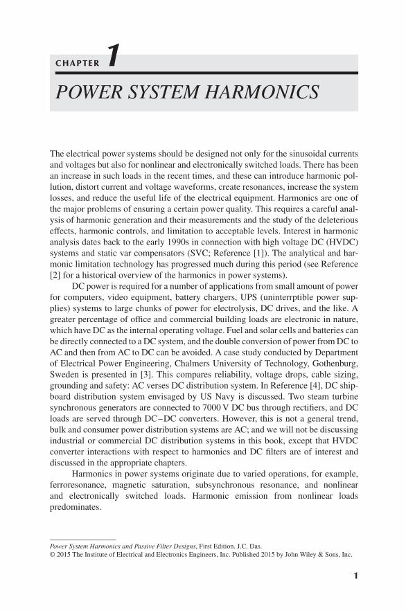
The electrical power systems should be designed not only for the sinusoidal currentsand voltages but also for nonlinear and electronically switched loads. There has beenan increase in such loads in the recent times, and these can introduce harmonic pol-lution, distort current and voltage waveforms, create resonances, increase the systemlosses, and reduce the useful life of the electrical equipment. Harmonics are one ofthe major problems of ensuring a certain power quality. This requires a careful anal-ysis of harmonic generation and their measurements and the study of the deleteriouseffects, harmonic controls, and limitation to acceptable levels. Interest in harmonicanalysis dates back to the early 1990s in connection with high voltage DC (HVDC)systems and static var compensators (SVC; Reference [1]). The analytical and har-monic limitation technology has progressed much during this period (see Reference[2] for a historical overview of the harmonics in power systems).
DC power is required for a number of applications from small amount of powerfor computers, video equipment, battery chargers, UPS (uninterrptible power sup-plies) systems to large chunks of power for electrolysis, DC drives, and the like. Agreater percentage of office and commercial building loads are electronic in nature,which have DC as the internal operating voltage. Fuel and solar cells and batteries canbe directly connected to a DC system, and the double conversion of power from DC toAC and then from AC to DC can be avoided. A case study conducted by Departmentof Electrical Power Engineering, Chalmers University of Technology, Gothenburg,Sweden is presented in [3]. This compares reliability, voltage drops, cable sizing,grounding and safety: AC verses DC distribution system. In Reference [4], DC ship-board distribution system envisaged by US Navy is discussed. Two steam turbinesynchronous generators are connected to 7000 V DC bus through rectifiers, and DCloads are served through DC–DC converters. However, this is not a general trend,bulk and consumer power distribution systems are AC; and we will not be discussingindustrial or commercial DC distribution systems in this book, except that HVDCconverter interactions with respect to harmonics and DC filters are of interest anddiscussed in the appropriate chapters.
Harmonics in power systems originate due to varied operations, for example,ferroresonance, magnetic saturation, subsynchronous resonance, and nonlinearand electronically switched loads. Harmonic emission from nonlinear loadspredominates.
Power System Harmonics and Passive Filter Designs, First Edition. J.C. Das.© 2015 The Institute of Electrical and Electronics Engineers, Inc. Published 2015 by John Wiley & Sons, Inc.
1

2 CHAPTER 1 POWER SYSTEM HARMONICS
1.1 NONLINEAR LOADS
To distinguish between linear and nonlinear loads, we may say that lineartime-invariant loads are characterized so that an application of a sinusoidal voltageresults in a sinusoidal flow of current. These loads display constant steady-stateimpedance during the applied sinusoidal voltage. Incandescent lighting is an exampleof such a load. The electrical motors not supplied through electronic converters alsoapproximately meet this definition. The current or voltage waveforms will be almostsinusoidal, and their phase angles displaced depending on power factor of the elec-trical circuit. Transformers and rotating machines, under normal loading conditions,approximately meet this definition. Yet, it should be recognized that flux wave in theair gap of a rotating machine is not sinusoidal. Tooth ripples and slotting in rotatingmachines produce forward and reverse rotating harmonics. Magnetic circuits cansaturate and generate harmonics. Saturation in a transformer on abnormally highvoltage produces harmonics, as the relationship between magnetic flux density Band the magnetic field intensity H in a magnetic material (the transformer core)is not linear. Yet, the harmonics emissions from these sources are relatively small(Chapter 3).
In a nonlinear device, the application of a sinusoidal voltage does not result ina sinusoidal flow of current. These loads do not exhibit constant impedance duringthe entire cycle of applied sinusoidal voltage. Nonlinearity is not the same as thefrequency dependence of impedance, that is, the reactance of a reactor changes inproportion to the applied frequency, but it is linear at each applied frequency if weneglect saturation and fringing. However, nonlinear loads draw a current that mayeven be discontinuous or flow in pulses for a part of the sinusoidal voltage cycle.
Mathematically, linearity implies two conditions:
• Homogeneity
• Superposition
Consider the state of a system defined in the state equation form:
⋅x = f [x(t), r(t), t] (1.1)
If x(t) is the solution to this differential equation with initial conditions x(t0) at t = t0and input r(t), t > t0:
x(t) = 𝜑[x(t0), r(t)] (1.2)
then homogeneity implies that
𝜑[x(t0), 𝛼r(t)] = 𝛼𝜑[x(t0), r(t)] (1.3)
where 𝛼 is a scalar constant. This means that x(t) with input 𝛼 r(t) is equal to 𝛼 timesx(t) with input r(t) for any scalar 𝛼.
Superposition implies that
𝜑[x(t0), r1(t) + r2(t)] = 𝜑[x(t0), r1(t)] + 𝜑[x(t0), r2(t)] (1.4)

1.2 INCREASES IN NONLINEAR LOADS 3
That is, x(t) with inputs r1(t) + r2(t) is equal to the sum of x(t) with input r1(t) andx(t) with input r2(t).Thus, linearity is superimposition plus homogeneity.
1.2 INCREASES IN NONLINEAR LOADS
Nonlinear loads are continuously on the increase. It is estimated that, during the next10 years, more than 60% of the loads on utility systems will be nonlinear. Also muchof the electronic load growth involves residential sector and household appliances.Concerns for harmonics originate from meeting a certain power quality, which leadsto the related issues of (1) effects on the operation of electrical equipment, (2) har-monic analysis, and (3) harmonic control. A growing number of consumer loads aresensitive to poor power quality, and it is estimated that power quality problems costUS industry tens of billion of dollars per year. Although the expanded use of con-sumer automation equipment and power electronics is leading to higher productivity,these heavy loads are a source of electrical noise and harmonics and are less tolerantto poor power quality. For example, adjustable speed drives (ASDs) are less tolerantto voltage sags and swells as compared to an induction motor; and a voltage dip of10% of certain time duration may precipitate ASD shutdown. These generate line har-monics and a source containing harmonics impacts their operation, leading to furthergeneration of harmonics. This implies that the nonlinear loads which are a sourceof generation of harmonics are themselves relatively less tolerant to the poor powerquality that originates from harmonic emission from these loads.
Some examples of nonlinear loads are as follows:
• ASD systems
• Cycloconverters
• Arc furnaces
• Rolling mills
• Switching mode power supplies
• Computers, copy machines, television sets, and home appliances
• Pulse burst modulation
• Static var compensators (SVCs)
• Thyristor-controlled reactors (TCRs)
• HVDC transmission, harmonics originate in converters
• Electric traction, chopper circuits
• Wind and solar power generation
• Battery charging and fuel cells
• Slip frequency recovery schemes of induction motors
• Fluorescent lighting and electronic ballasts
• Electrical vehicle charging systems
• Silicon-controlled rectifier (SCR) heating, induction heating, and arc welding.
4 CHAPTER 1 POWER SYSTEM HARMONICS
The harmonics are also generated in conventional power equipment, such astransformer and motors. Saturation and switching of transformers generate harmon-ics. The harmonic generation is discussed in Chapters 3–5. The application of capaci-tor banks for power factor corrections and reactive power support can cause resonanceand further distortions of waveforms (Chapter 9). Earlier rotating synchronous con-densers have been replaced with modern shunt capacitors or SVCs (Chapter 4).
1.3 EFFECTS OF HARMONICS
Harmonics cause distortions of the voltage and current waveforms, which haveadverse effects on electrical equipment. The estimation of harmonics from nonlinearloads is the first step in a harmonic analysis, and this may not be straightforward.There is an interaction between the harmonic producing equipment, which can havevaried topologies, and the electrical system. Over the course of years, much attentionhas been focused on the analysis and control of harmonics, and standards have beenestablished for permissible harmonic current and voltage distortions (Chapter 10).The effects of harmonics are discussed in Chapter 8.
1.4 DISTORTED WAVEFORMS
Harmonic emissions can have varied amplitudes and frequencies. The most com-mon harmonics in power systems are sinusoidal components of a periodic waveform,which have frequencies that can be resolved into some multiples of the fundamentalfrequency. Fourier analysis is the mathematical tool employed for such analysis, andChapter 2 provides an overview.
The components in a Fourier series that are not an integral multiple of the powerfrequency are called noninteger harmonics (Chapter 5).
The distortion produced by nonlinear loads can be resolved into a number ofcategories:
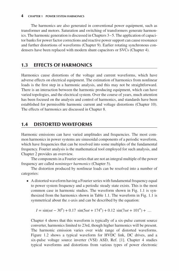
• A distorted waveform having a Fourier series with fundamental frequency equalto power system frequency and a periodic steady state exists. This is the mostcommon case in harmonic studies. The waveform shown in Fig. 1.1 is syn-thesized from the harmonics shown in Table 1.1. The waveform in Fig. 1.1 issymmetrical about the x-axis and can be described by the equation:
I = sin(𝜔t − 30∘) + 0.17 sin(5𝜔t + 174∘) + 0.12 sin(7𝜔t + 101∘) + …
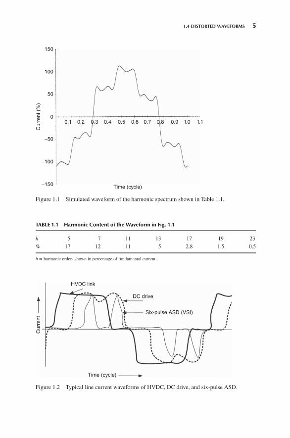
Chapter 4 shows that this waveform is typically of a six-pulse current sourceconverter, harmonics limited to 23rd, though higher harmonics will be present.The harmonic emission varies over wide range of distorted waveforms.Figure 1.2 shows a typical waveform for HVDC link, DC drives, and asix-pulse voltage source inverter (VSI) ASD, Ref. [1]. Chapter 4 studiestypical waveforms and distortions from various types of power electronic
1.4 DISTORTED WAVEFORMS 5
150
100
50
0
−50
−100
−150
Curr
ent (%
)
0.1 0.2 0.3 0.4 0.5 0.6 0.7 0.8 0.9 1.0 1.1
Time (cycle)
Figure 1.1 Simulated waveform of the harmonic spectrum shown in Table 1.1.
TABLE 1.1 Harmonic Content of the Waveform in Fig. 1.1
h 5 7 11 13 17 19 23
% 17 12 11 5 2.8 1.5 0.5
h = harmonic orders shown in percentage of fundamental current.
Curr
ent
HVDC link
DC drive
Six-pulse ASD (VSI)
Time (cycle)
Figure 1.2 Typical line current waveforms of HVDC, DC drive, and six-pulse ASD.

6 CHAPTER 1 POWER SYSTEM HARMONICS
100C
urr
ent (k
A)
Time (sec)
0 10Figure 1.3 Erratic current signature of anelectric arc furnace during scrap melting.
switching equipment. This is the most common situation in practice, and thedistorted waveforms can be decomposed into a number of harmonics. Thesystem can usually be modeled as a linear system.
• A distorted waveform having a submultiple of power system frequency and aperiodic steady state exists. Certain types of pulsed loads and integral cyclecontrollers produce these types of waveforms (Chapters 4 and 5).
• The waveform is aperiodic, but perhaps almost periodic. A trigonometric seriesexpansion may still exist. Examples are arcing devices: arc furnaces, fluores-cent, mercury, and sodium vapor lighting. The process is not periodic in nature,and a periodic waveform is obtained if the conditions of operation are kept con-stant for a length of time. Consider the current signature of an arc furnace duringscrap melting (Fig. 1.3). The waveform is highly distorted and aperiodic. Yet,typical harmonic emissions from arc furnace during melting and refining havebeen defined in IEEE standard 519 [5].
The arc furnace loads are highly polluting and cause phase unbalance, flicker,impact loading, harmonics, interharmonics, and resonance, and may give rise to tor-sional vibrations in rotating equipment.
1.4.1 Harmonics and Power Quality
Harmonics are one of the major power quality concerns. The power quality concernsembrace much wider concerns such as voltage sags and swells, transients, under andovervoltages, frequency variations, outright interruptions, power quality for sensitiveelectronic equipment such as computers. Table 3.1 summarizes some power qualityproblems. A reference of importance is IEEE Recommended Practice for Emergencyand Standby Power Systems for Industrial and Commercial Applications, [6]. Thisbook is not about power quality; however, some important publications are separatelylisted in References for the interested readers.