power quality solutions - allied electronics power factor correction power quality solutions product...
TRANSCRIPT

www.epcos.com
Power Factor CorrectionP o w e r Q u a l i t y S o l u t i o n s
Product Profile 2007
1201070039_PFC_Katalog_07.qxd 14.08.2007 16:02 Uhr Seite 1

2 EPCOS AGEPCOS AG2
EPCOS is a leading manufacturer of electronic components and modules and provides one-stop shopping for a comprehensive range of products. Ourportfolio includes capacitors and inductors, ceramic components, arresters, andsurface and bulk acoustic wave components. As an innovative technology-drivencompany, EPCOS focuses on fast-growing and technologically demandingmarkets in the areas of information and communications technology, automotive,industrial, and consumer electronics. We offer our customers both standardcomponents as well as application-specific solutions.
EPCOS has design, manufacturing and marketing facilities in Europe, Asia and the Americas. Increasingly, we are expanding our global research anddevelopment network by intensifying R&D activities at our production locations,primarily in Eastern Europe, China and India. With our global presence we are ableto provide our customers with local development know-how and support in theearly phases of their projects.
EPCOS is continually improving its processes and thus the quality of its productsand services. The Group is ISO/TS 16949 certified and remains committed toconstantly reviewing and systematically improving its quality management system.
Welcome to the World of Electronic Components and Modules
1201070039_PFC_Katalog_07.qxd 14.08.2007 16:02 Uhr Seite 2

EPCOS AG 33
Power Factor Correction
ContentsPreview 4
PFC capacitor series overview 6
Information about PFC capacitors n Design of capacitors 8n Important notes 10n Cautions 11
PFC capacitorsn PhaseCap Premium capacitors (230 … 525 V, 5.0 … 33.0 kvar/premium) 14n PhaseCap HD capacitors (400 … 525 V, 40.0 … 60.0 kvar/heavy duty) 20n WindCap capacitors (690 … 800 V, 5.0 … 36.0 kvar/wind turbine) 24n PhiCap capacitors (230 … 525 V, 0.5 … 30.0 kvar/economical) 28n MKV capacitors (400 … 690 V, 5.0 … 18.0 kvar/up to +70 °C
ambient temperature) 36
PFC controllersn BR604 and BR6000 series 38
Capacitor contactors 42
Reactorsn Antiresonance harmonic filter: reactors 46n Discharge reactor 52
Dynamic power factor correction n Thyristor module TSM-LC, TSM-HV 54
Fundamentals of power factor correction 58
Addresses 79
1201070039_PFC_Katalog_07.qxd 14.08.2007 16:02 Uhr Seite 3

4 EPCOS AG
PreviewGeneral
Awareness of the necessity of powerquality is increasing, and power fac-tor correction (PFC) will be imple-mented on a growing scale in future.Enhancing power quality – improve-ment of power factor – saves costsand ensures a fast return on invest-ment.
In power distribution, in low- andmedium-voltage networks, PFCfocuses on the power flow (cos ϕ)and the optimization of voltagestability by generating reactive pow-er – to improve voltage quality andreliability at distribution level.
How reactive power is generated
Every electric load that works withmagnetic fields (motors, chokes,transformers, inductive heating, arc-welding generators) produces avarying degree of electrical lag,which is called inductance. This lagof inductive loads maintains the cur-rent sense (e.g. positive) for a timeeven though the negative-going volt-age tries to reverse it. This phaseshift between current and voltage ismaintained, current and voltagehaving opposite signs. During thistime, negative power or energy isproduced and fed back into the net-work. When current and voltagehave the same sign again, the sameamount of energy is again needed tobuild up the magnetic fields in induc-tive loads. This magnetic reversalenergy is called reactive power.
In AC networks (50 /60 Hz) such aprocess is repeated 50 or 60 times asecond. So an obvious solution is tobriefly store the magnetic reversalenergy in capacitors and relieve thenetwork (supply line) of this reactiveenergy.
For this reason, automatic reactivepower compensation systems (de-tuned / conventional) are installed forlarger loads like industrial machinery.Such systems consist of a group of capacitor units that can be cut in and cut out and which are drivenand switched by a power factorcontroller.
1201070039_PFC_Katalog_07.qxd 14.08.2007 16:02 Uhr Seite 4

EPCOS AG 5
Power factorLow power factor (cos ϕ)
Low cos ϕ results in
n higher energy consumption andcosts,
n less power distributed via thenetwork,
n power loss in the network,n higher transformer losses,n increased voltage drop in power
distribution networks.
Power factor improvement
Power factor improvement can beachieved by
n compensation of reactive powerwith capacitors,
n active compensation – using semi-conductors,
n overexcited synchronous machine(motor /generator).
Types of PFC (detuned or conventional)
n individual or fixed compensation(each reactive power producer isindividually compensated),
n group compensation (reactivepower producers connected as a group and compensated as awhole),
n central or automatic compensa-tion (by a PFC system at a centralpoint),
n mixed compensation.
PFC controller
Capacitor contactor
Harmonicssuppressionreactor
TransformerLowvoltage
Grid highvoltage
Protection
Load structureDischargereactor
Dynamic PFC
Currenttransformer
Capacitor
M
M
3~
3~
1201070039_PFC_Katalog_07.qxd 14.08.2007 16:02 Uhr Seite 5

PFC Capacitor Series Overview
Gen
eral
6 EPCOS AGPlease read Important notes on page 10 and Cautions on page 11–13.
PFC capacitor series for power factor correction and detuned filter
Parameter Symbol /unit PhaseCap™ Premium PhaseCap™ HD
Power QR [kvar] 5.0 ... 33.0 40.0 ... 60.0
Rated voltage VR [VAC] 230 ... 525 400 ... 525
Inrush current IS [A] up to 200 · IR up to 200 · IRTemperature class –40/D –25/D
max. temp. 55 °C max. temp. 55 °Cmax. mean 24 h = 45 °C max. mean 24 h = 45 °Cmax. mean 1 year = 35 °C max. mean 1 year = 35 °C
Losses:– Dielectric QL [W/kvar] < 0.2 < 0.2– Total* QL [W/kvar] < 0.45 < 0.35
Max. humidity Hrel 95% 95%
Safety – triple (self-healing, overpressure triple (self-healing, overpressuredisconnector, dry technology) disconnector, dry technology)
Impregnation – inert gas inert gas, Nitrogen (N2)
Mean life DB(co) up to 115000 h up to 130000 hexpectancyConnection – SIGUT™, block-type, SIGUT™, block-type,
safety terminal safety terminal
Cooling – natural natural
Case / shape – aluminum/cylindrical aluminum/cylindrical
Enclosure IPxx IP20, optionally IP54 IP20
Standard IEC 60831-1+2, UL 810 5th edition, IEC 60831-1+2, UL 810 5th editioncUL file # E238746
Application PFC and detuned systems PFC and detuned systems
* Without discharge resistor
1201070039_PFC_Katalog_07.qxd 14.08.2007 16:02 Uhr Seite 6

PFC Capacitor Series Overview
Gen
eral
EPCOS AG 7Please read Important notes on page 10 and Cautions on page 11–13.
PFC capacitor series for power factor correction and detuned filter
WindCap™ PhiCap MKV
5.0 ... 36.0 0.5 ... 30.0 5.0 … 18.0
690 ... 800 230 ... 525 400 … 690
up to 300 · IR up to 200 · IR up to 300 · IR–40/D –25/D –25 ... +70 °Cmax. temp. 55 °C max. temp. 55 °C max. temp. 70 °Cmax. mean 24 h = 45 °C max. mean 24 h = 45 °C max. mean 24 h = 55 °Cmax. mean 1 year = 35 °C max. mean 1 year = 35 °C max. mean 1 year = 45 °C
< 0.2 < 0.2 < 0.2< 0.4 < 0.45 < 0.5
95% 95% 95%
triple (self-healing, overpressure dual (self-healing, overpressure dual (self-healing, overpressuredisconnector, dry technology) disconnector) disconnector)
inert gas, Nitrogen (N2) soft resin oil
up to 130000 h up to 100000 h up to 150000 h
SIGUT™, block-type, B32344 series: SIGUTTM
safety terminal SIGUT™, block-type, safety terminalB32340 /B32343 series:fast-on terminals
natural natural natural
aluminum/cylindrical aluminum/cylindrical aluminum/cylindrical
IP20, optionally IP54 IP00, IP20, optionally IP54 IP00
IEC 60831-1+2, UL 810 5th edition IEC 60831-1+2, UL 810 5th edition IEC 60831-1+2cUL file # E238746 cUL file # E106388
PFC, detuned systems and wind turbines PFC and detuned systems PFC and harmonic filtering
1201070039_PFC_Katalog_07.qxd 14.08.2007 16:02 Uhr Seite 7

Information about PFC Capacitors
Design of capacitors
MKK /MKP technology
The broad field of application for ca-pacitors combined with physical andeconomic considerations createsthe need for different dielectric tech-nologies.
When it comes to low-voltage powerfactor correction, MKK/MKP tech-nology (metalized plastic film /poly-propylene) has turned out as cur-rently the most suitable and mosteconomic technology. The thicknessof the dielectric differs as a functionof voltage rating. The metalization(with zinc and aluminum as its majorconstituents) and edge enhance-ment with extra junctions or cross-
profile metalization play a significantrole in achieving high currenthandling and stable capacitance.Heavy edge and special film cuttingtechnique (optimized combination ofwavy and smooth cuts) produces amaximum effective surface for themetal spraying or contacting pro-cess (winding design). This results inhigh surge current withstand capa-bility. The buckling effect on the filmedge of the winding – the cause ofcontact edge problems – is eliminat-ed in this way.
Vacuum impregnation
The active winding elements areheated and then dried for a definedperiod. Impregnation (e.g. by gas) isperformed under vacuum. In this wayair and moisture are extracted fromthe inner capacitor, and oxidation ofthe electrodes as well as partial dis-charges are avoided. Afterwards ca-pacitors are hermetically sealed incases (e.g. aluminum). The elaborateprocess ensures excellent capaci-tance stability and long useful life.
Gen
eral
8 EPCOS AGPlease read Important notes on page 10 and Cautions on page 11–13.
Wavy cut design
Section A
Capacitorwindings
Metal spray
Core
Film and film-free margin
Metalization
Metalization
Heavy edge
EPCOS wavy cut
Section A
Without EPCOSwavy cut
Solid contact zone
Crackspossible
Flame-sprayed area
Heavy edge
Flame-sprayedcontact area (Zn)
Large effectivecontact area
Metalization
1201070039_PFC_Katalog_07.qxd 14.08.2007 16:02 Uhr Seite 8

Information about PFC Capacitors
Gen
eral
EPCOS AG 9
Self-healing
An electric breakdown is possible asthe result of thermal or electric over-load or at the end of useful life. This re-sults in a small arc that evaporates themetalization in the region of the break-down in a matter of microseconds.The gas pressure caused at this spotby the high temperature blows thenow vaporous metalization out of thebreakdown region. This means that anon-conducting isolation region freeof metalization is formed here.
During and after the breakdownthe capacitor is fully functional. Thereduction in capacitance caused byself-healing is less than 100 pF, i.e. ofan order that can only be verified bya precision measuring instrument.
Overpressure disconnector
Electrical components do not haveunlimited life expectancy; this appliesto self-healing capacitors too. As polypropylene-type capacitors sel-dom produce a pronounced shortcircuit, HCR fuses or circuit breakersalone do not offer sufficient protection.
All capacitors featured in this catalogare consequently fitted with a discon-nector that responds only to over-pressure. If numerous electric break-downs occur over time or as the re-sult of thermal or electric overload(within IEC 60831 specification), theformation of gas produces a rise inpressure inside the capacitor case.This causes a change in length be-cause of curvature of the lid orstretching of the expansion bead. Ex-pansion beyond a certain degree willseparate the internal wires and dis-connect the capacitor from the line.
V Caution: To ensure full functionality of an over-pressure disconnector, the followingis required:
1. The elastic elements must not behindered, i.e.– connecting lines must be flexible
leads (cables),– there must be sufficient space
for expansion above the con-nections (stated for the differentmodels),
– folding beads must not be re-tained by clamps.
2. Maximum allowed fault current of10000 A in accordance withUL 810 standard must not be ex-ceeded.
3. Stress parameters of the capaci-tor must be within IEC 60831specification.
Please read Important notes on page 10 and Cautions on page 11–13.
Self-healing
x
r1 10
4 2
42
6
6
8 10 1
2 4
245
5
10 101
1
399 7
37 9
1 Dielectric2 Metalized electrodes3 Material displacing shock wave4 Air gap with metal vapor
5, 6 Plasma zone7 Boundary layer between gas phase dielectric and plasma8 Breakdown channel9 Gas phase dielectric
10 Zone of displaced metalization and dielectric (isolating region)
Overpressure disconnector
Solid connected
Overpressure disconnector activated
Pressure
Expansion topExpansion bead
30 μm 10 μm
1201070039_PFC_Katalog_07.qxd 14.08.2007 16:02 Uhr Seite 9

Important Notes
Cau
tions
10 EPCOS AG
The following applies to all products named in thispublication:
1. Some parts of this publication contain statementsabout the suitability of our products for certainareas of application. These statements are based onour knowledge of typical requirements that are oftenplaced on our products in the areas of application con-cerned. We nevertheless expressly point out that suchstatements cannot be regarded as binding state-ments about the suitability of our products for aparticular customer application. As a rule, EPCOS iseither unfamiliar with individual customer applicationsor less familiar with them than the customers them-selves. For these reasons, it is always ultimately in-cumbent on the customer to check and decidewhether an EPCOS product with the properties de-scribed in the product specification is suitable for usein a particular customer application.
2. We also point out that in individual cases, a mal-function of electronic components or failurebefore the end of their usual service life cannot becompletely ruled out in the current state of the art, even if they are operated as specified. Incustomer applications requiring a very high level ofoperational safety and especially in customer applica-tions in which the malfunction or failure of an electroniccomponent could endanger human life or health (e.g.in accident prevention or life-saving systems), it musttherefore be ensured by means of suitable design of the customer application or other action taken by thecustomer (e.g. installation of protective circuitry orredundancy) that no injury or damage is sustained bythird parties in the event of malfunction or failure of anelectronic component.
3. The warnings, cautions and product-specific notesmust be observed.
4. In order to satisfy certain technical requirements, someof the products described in this publication maycontain substances subject to restrictions in cer-tain jurisdictions (e.g. because they are classed as “hazardous”). Useful information on this will befound in our Material Data Sheets on the Internet(www.epcos.com/material). Should you have any moredetailed questions, please contact our sales offices.
5. We constantly strive to improve our products. Conse-quently, the products described in this publicationmay change from time to time. The same is true ofthe corresponding product specifications. Pleasecheck therefore to what extent product descriptionsand specifications contained in this publication are stillapplicable before or when you place an order.
We also reserve the right to discontinue productionand delivery of products. Consequently, we cannotguarantee that all products named in this publicationwill always be available.
6. Unless otherwise agreed in individual contracts, allorders are subject to the current version of the“General Terms of Delivery for Products andServices in the Electrical Industry” published bythe German Electrical and Electronics IndustryAssociation (ZVEI).
7. The trade names EPCOS, BAOKE, Alu-X, CeraDiode, CSSP, MiniBlue, MKK, MLSC, MotorCap,PCC, PhaseCap, PhaseMod, SIFERRIT, SIFI,SIKOREL, SilverCap, SIMDAD, SIMID, SineFormer, SIOV, SIP5D, SIP5K, ThermoFuse, WindCap are trademarks registered or pending in Europe and in other countries. Further information will be foundon the Internet at www.epcos.com/trademarks.
1201070039_PFC_Katalog_07.qxd 14.08.2007 16:02 Uhr Seite 10

Cautions
Cau
tions
EPCOS AG 11Please read Important notes on page 10 and Cautions on page 11–13.
Temperature class of capacitors tostandard IEC 60831-1
Capacitors are divided into tem-perature classes. Each class isrepresented by a number followed bya letter, e.g. –25/D. The number isthe lowest ambient temperature atwhich a capacitor may operate. Theupper limit temperature is indicatedby the letter (see table above).
The useful life of a capacitor dependsvery much on temperature. Propercooling of a capacitor must ensurethat the maximum temperature is notexceeded, otherwise useful life is de-graded. When configuring a circuit,one should make sure that capaci-tors are not subjected to heat fromadjacent components (reactors, busbars, etc). Forced cooling is prefer-able for compact designs. And it ishighly inadvisable to arrange capaci-
tors directly above reactors. Exceed-ing specified temperature limits mayset in worst case the safety deviceout of operation.
Enclosure of capacitors (IPxx)
For different models there aredifferent types of enclosure. The typeof enclosure is indicated by a desig-nation consisting of the two letters IPfollowed by two digits.
Current rating/maximum admissibleovercurrent
The rated current (IR) is the currentresulting for rated voltage (VR)and frequency (in Hz), excluding tran-sients. Maximum permitted RMScurrent for each particular capacitoris specified in the data sheet.Continuously exceeding of the nomi-nal current will lead to increased self-
heating of the capacitor and reducelife time. The maximum admissibleovercurrent (Imax) of 1.3 · IR to IEC60831 standard is maintained by allcapacitors in this catalog. The figuresfor overcurrent allow for the com-bined effects of harmonics, over-voltage and capacitance tolerance.
Maximum admissible overvoltage
Capacitors from EPCOS are suitablefor operation on overvoltages quotedby IEC 60831 (see table). Overvolt-ages higher than 1.15 · VR reduce lifetime of the capacitor and must not occur more than 200 times during life time of capacitor. Overvoltagesabove 1.3 · VR must not occur at all,appropriate overvoltage protection(e.g. against lightning strikes) must be ensured.
Enclosure First digit Second digit
IP00 No protection against finger touch and ingress of solid foreign bodies No protection against ingressof water
IP20 Protection against finger touch and solid foreign bodies ≥ 12.5 mm diameter No protection against ingressof water
IP41 Protection against tool touch and solid foreign bodies ≥ 1 mm diameter Drip-water protection
IP54 Protection against tool touch and solid foreign bodies ≥ 1 mm diameter, Splash water protectionprotection against dust deposit
Temperature class of capacitors (according IEC 60831-1)
Enclosure of capacitors (IPxx)
Frequency (50 /60 Hz) Max. voltage (Vrms) Max. duration Remarks
Line frequency 1.00 · VR Continuous duty Highest mean during entire operating time of capacitor; exceptions (see below) are admissible for times of < 24 h
Line frequency 1.10 · VR 8 h daily Line voltage fluctuations
Line frequency 1.15 · VR 30 min daily Line voltage fluctuations
Line frequency 1.20 · VR 5 min daily Line voltage fluctuations
Line frequency 1.30 · VR 1 min daily Line voltage fluctuations
Line frequency Such that current does not exceed maximum admissible figure (Imax. = 1.3 · IR)with harmonics
Maximum admissible overvoltage
Temperature class Temperature of capacitor surrounding air
Maximum Maximum mean for 24 h Maximum mean for 1 year
B 45 °C 35 °C 25 °C
C 50 °C 40 °C 30 °C
D 55 °C 45 °C 35 °C
1201070039_PFC_Katalog_07.qxd 14.08.2007 16:02 Uhr Seite 11

Cautions
Mean life expectancy
The mean life expectancy of powercapacitors is mainly governed by thefollowing factors:– duration of overload,– ambient temperature and the re-
sulting case temperature,– maximum rms current and the re-
sulting case temperature,– voltage height and duration.
The calculated life expectancy of thevarious series is stated for nominaloperating conditions. If componentsare stressed less than the IEC 60831factors, longer useful life can beexpected, and a correspondinglyshorter one or increased failure rate ifnominal parameters are exceeded.
Fuse protection
Power capacitors have to be pro-tected against short circuits by fusesor thermal magnetic overcurrent re-lays. Slow-blow, low-voltage high-breaking-capacity fuses (HRC) arepreferable. The fuse rating should be1.6 to 1.8 times the rated current ofthe capacitor. Magnetic short circuitrelays should be set to between9 and 12 times rated current to pre-vent them responding to high inrushcurrents. Maximum allowed faultcurrent of 10 000 A in accordancewith UL 810 standard must be en-sured by the application design.
V HRC fuses must not be usedfor switching. Resulting electricarcing can cause death! It mayalso cause capacitor failures,and result, worst case, in capac-itor bursting and fire.
Switching of capacitors
When a capacitor is switched to anAC system, the result is a resonantcircuit damped to a greater or lesserdegree. In addition to the rated cur-
rent, the capacitor accepts a tran-sient current that is a multiple of (upto 200 times) its rated current. Fastswitching, low-bounce contactorsshould be used, and have theswitching capacity for capacitivecurrents stated by the producer.Special capacitor contactors withleading contacts that featureprecharging resistors to damp inrushcurrents are recommended. As perIEC 60831 standard, a maximum of5000 switching operations per yearis acceptable. Before considering ahigher number of switching opera-tions, please contact EPCOS.
Discharging
Capacitors must be discharged to amaximum of 10% of rated voltagebefore they are switched in again.This prevents an electric impulse dis-charge in the application, influencesthe capacitor’s useful life in PFC sys-tems, and protects against electricshock. The capacitor must be dis-charged to 75 V or less within 3 min.There must not be any switch, fuse orany other disconnecting device in thecircuit between the power capacitorand the discharging device. EPCOSsupplies capacitor discharge resis-tors to all series, alternatively dis-charge reactors are available.
V Caution: Discharge and shortcircuit capacitor before handling!
Capacitors in networks with harmonics
Harmonics are produced in the oper-ation of electric loads with a non-linear voltage /current characteristic(e.g. rectifiers and inverters for drives,welding apparatus and uninterrupt-ible power supplies). Harmonics aresinusoidal voltages and currents with higher frequencies of a multiple of the 50 or 60 Hz line frequency.
In low-voltage three-phase systemsthe 5th and 7th harmonics are espe-cially troublesome. Detuned capac-itors should be used for power factorcorrection in systems subject to har-monics. These represent a seriesresonant circuit of power capacitorand reactor. The circuit is tuned sothat the series resonant frequency isbelow the lowest harmonics appear-ing in the system. This produces aninductive response to all frequenciesabove the series resonant frequency,avoiding resonances with system in-ductances. Depending on the se-lected series resonant frequency,part of the harmonic current is takenup by the detuned power capaci-tors. The remainder of the harmoniccurrent flows into the superordinatesystem. The use of detuned powercapacitors thus contributes to re-ducing voltage distortion throughharmonics and lessens the disturb-ing effect on proper operation ofother electric loads.
Most international standards limitTHD-V on LV side to 5%. However ithas to be noted that in many gridsthese levels are exceeded and evenlower distortion, e.g. 3–4% THD-Vcan generate extreme overcurrentsin case of resonance condition.
Maximum overcurrents as specifiedunder technical data of each seriesmust not be exceeded.
Resonance must be avoided by ap-propriate panel design. Resonancemay cause very high overcurrentswhich can lead to capacitor failures,and worst case, to explosion and fire.
Cau
tions
12 EPCOS AGPlease read Important notes on page 10 and Cautions on page 11–13.
1201070039_PFC_Katalog_07.qxd 14.08.2007 16:02 Uhr Seite 12

Cautions
Installation
Specifications like IEC 61921,VDE 0100, VDE 0101, VDE 0560part 4 and 46, EN 60831 andIEC 60831 apply to the installationand operation of power capacitors.Capacitors should be sited in cooland well ventilated locations awayfrom other heat-radiating elements.Natural heat dissipation is generallysufficient for cooling purposes ifenough air is able to flow to and awayfrom them and the capacitors are
spaced at least 20 mm apart.Otherwise, in a less well ventilatedenvironment, forced cooling (fans)will be necessary, scaled so that themaximum admissible ambient tem-perature is not exceeded.
Useful life of capacitors strongly de-pends on the operating temperature(refer to page 11, temperature classesof capacitors).
Exceeding maximum allowed tem-perature may set the safety deviceout of operation.
Please read chapter Installation andMaintenance on page 63.
Note
Products shown in this catalog re-flect typical specifications. You arekindly requested to approve ourproduct specifications or request ourapproval for your specification beforeordering.
Cau
tions
EPCOS AG 13Please read Important notes on page 10 and Cautions on page 11–13.
Mechanical damage
In case of dents or any other mechanical damage, ca-pacitors must not be used at all.
Vibration resistance
The resistance to vibration of capacitors corresponds toIEC 68, part 2–6.
Max. test conditions:
Test duration 2 h
Frequency range 10 ... 55 Hz correspondingto max. 0.7 g
Displacement 0.75 mmamplitude
Because the fixing and the terminals may influence thevibration properties, it is necessary to check stabilitywhen a capacitor is built in and exposed to vibration.Irrespective of this, you are advised not to locate capac-itors where vibration amplitude reaches the maximum instrongly vibrating equipment.
Connection
Make sure connection cables are of flexible type or flex-ible copper bands are used. This is mandatory to allowthe overpressure disconnector work and avoid mechan-ical stress on the terminals and feedthroughs.
The connection cables to the capacitor should be de-signed for a current of at least 1.5 times the rated cur-rent so that no heat is conducted into the capacitor. If re-actors are used in an application, the distance betweenreactor and capacitor must be great enough so that noheat of the reactors, which are operating at a much high-er temperature level, is conducted via connection cableto the capacitors.
Avoid bending cable lugs, cables or other mechanicalforce on the terminals. Otherwise leakages may set thesafety device out of operation.
Ensure firm fixing of terminals, fixing torque to be appliedas per individual specification.
Maximum specified terminal current (please refer totechnical data of specific series) must not be exceededat any case.
Grounding
The threaded bottom stud of the capacitor has to beused for grounding. In case grounding is done via metalchassis that the capacitor is mounted to, the layer ofvarnish beneath the washer and nut should be removed.
Storage and operating conditions
Do not use or store capacitors in corrosive atmosphere,especially where chloride gas, sulfide gas, acid, alkali,salt or the like are present. In dusty environments regu-lar maintenance and cleaning especially of the terminalsis required to avoid conductive path between phasesand /or phases and ground.
1201070039_PFC_Katalog_07.qxd 14.08.2007 16:02 Uhr Seite 13
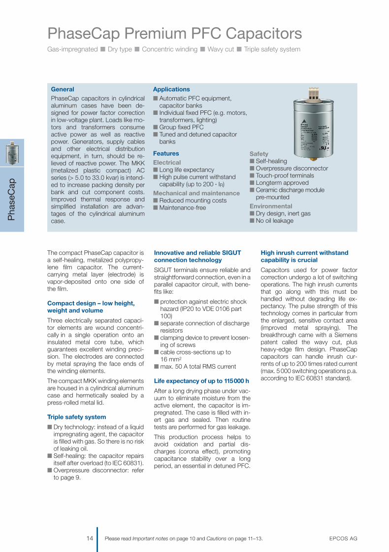
PhaseCap Premium PFC CapacitorsGas-impregnated n Dry type n Concentric winding n Wavy cut n Triple safety system
The compact PhaseCap capacitor isa self-healing, metalized polypropy-lene film capacitor. The current-carrying metal layer (electrode) isvapor-deposited onto one side of the film.
Compact design – low height,weight and volume
Three electrically separated capaci-tor elements are wound concentri-cally in a single operation onto aninsulated metal core tube, whichguarantees excellent winding preci-sion. The electrodes are connectedby metal spraying the face ends ofthe winding elements.
The compact MKK winding elementsare housed in a cylindrical aluminumcase and hermetically sealed by apress-rolled metal lid.
Triple safety system
n Dry technology: instead of a liquidimpregnating agent, the capacitoris filled with gas. So there is no riskof leaking oil.
n Self-healing: the capacitor repairsitself after overload (to IEC 60831).
n Overpressure disconnector: referto page 9.
Innovative and reliable SIGUTconnection technology
SIGUT terminals ensure reliable andstraightforward connection, even in aparallel capacitor circuit, with bene-fits like:
n protection against electric shockhazard (IP20 to VDE 0106 part100)
n separate connection of dischargeresistors
n clamping device to prevent loosen-ing of screws
n cable cross-sections up to16 mm2
n max. 50 A total RMS current
Life expectancy of up to 115000 h
After a long drying phase under vac-uum to eliminate moisture from theactive element, the capacitor is im-pregnated. The case is filled with in-ert gas and sealed. Then routinetests are performed for gas leakage.
This production process helps toavoid oxidation and partial dis-charges (corona effect), promotingcapacitance stability over a longperiod, an essential in detuned PFC.
High inrush current withstandcapability is crucial
Capacitors used for power factorcorrection undergo a lot of switchingoperations. The high inrush currentsthat go along with this must behandled without degrading life ex-pectancy. The pulse strength of thistechnology comes in particular fromthe enlarged, sensitive contact area(improved metal spraying). Thebreakthrough came with a Siemenspatent called the wavy cut, plusheavy-edge film design. PhaseCapcapacitors can handle inrush cur-rents of up to 200 times rated current(max. 5000 switching operations p.a.according to IEC 60831 standard).
Pha
seC
ap
14 EPCOS AGPlease read Important notes on page 10 and Cautions on page 11–13.
GeneralPhaseCap capacitors in cylindricalaluminum cases have been de-signed for power factor correctionin low-voltage plant. Loads like mo-tors and transformers consumeactive power as well as reactivepower. Generators, supply cablesand other electrical distributionequipment, in turn, should be re-lieved of reactive power. The MKK(metalized plastic compact) ACseries (> 5.0 to 33.0 kvar) is intend-ed to increase packing density perbank and cut component costs.Improved thermal response andsimplified installation are advan-tages of the cylindrical aluminumcase.
Applicationsn Automatic PFC equipment,
capacitor banksn Individual fixed PFC (e.g. motors,
transformers, lighting)n Group fixed PFCn Tuned and detuned capacitor
banks
FeaturesElectricaln Long life expectancyn High pulse current withstand
capability (up to 200 · IR)Mechanical and maintenancen Reduced mounting costsn Maintenance-free
Safetyn Self-healingn Overpressure disconnectorn Touch-proof terminalsn Longterm approvedn Ceramic discharge module
pre-mountedEnvironmentaln Dry design, inert gasn No oil leakage
1201070039_PFC_Katalog_07.qxd 14.08.2007 16:02 Uhr Seite 14

PhaseCap Premium PFC CapacitorsGas-impregnated n Dry type n Concentric winding n Wavy cut n Triple safety system
Pha
seC
ap
EPCOS AG 15Please read Important notes on page 10 and Cautions on page 11–13.
Technical data and limit values
Standards IEC 60831-1+2, EN 60831-1+2, UL 810 5th edition
Overvoltage Vmax VR + 10% (up to 8 h daily) / VR + 15% (up to 30 min daily) /VR + 20% (up to 5 min daily) / VR + 30% (up to 1 min daily)
Overcurrent Imax up to 1.3 · IR (up to 1.5 · IR including combined effects of harmonics, overvoltages and capacitance tolerance)
Inrush current IS up to 200 · IR
Losses:– Dielectric < 0.2 W/kvar– Total* < 0.45 W/kvar
Rated frequency f 50 /60 Hz
Capacitance tolerance –5% / +10%
Test voltage, terminal / terminal VTT 2.15 · VR1, AC, 10 s
Test voltage, terminal /case VTC up to VR ≤ 660 V: 3000 VAC, 10 s; above VR = 660 V: 6000 VAC, 10 s
Mean life expectancy t LD(Co) up to 115000 h
Ambient temperature –40/D; max. temp. 55 °C; max. mean 24 h = 45 °C; max. mean 1 year = 35 °C; lowest temperature = –40 °C
Cooling natural or forced
Humidity Hrel max. 95%
Altitude max. 4000 m above sea level
Mounting position random
Mounting and grounding threaded M12 stud on bottom of case
Safety dry technology, overpressure disconnector, self-healing, maximum allowed fault current 10000 A in accordance with UL 810 standard
Discharge module ceramic discharge module premounted,discharge time ≤ 75 V in 60 s; ≤ 75 V in 90 s for types marked with4)
Case extruded aluminum can
Enclosure IP20, indoor mounting (optionally with terminal cap for IP54)
Dielectric polypropylene film
Impregnation inert gas, Nitrogen (N2)
Terminals SIGUT terminal strip with electric shock protection (IP20), (VDE 0106part 100), max. 16 mm2 cable cross-section, max. current 50 A
Certification cUL file # E238746
Number of switching operations max. 5000 switchings per year according to IEC 60831-1+/2
* Without discharge resistor
1201070039_PFC_Katalog_07.qxd 14.08.2007 16:02 Uhr Seite 15

PhaseCap Premium PFC CapacitorsGas-impregnated n Dry type n Concentric winding n Wavy cut n Triple safety system
Pha
seC
ap
16 EPCOS AGPlease read Important notes on page 10 and Cautions on page 11–13.
Three-phase capacitors
Customized products available upon request. Minimum order quantity 200 pieces.
1) Temperature class deviation –40/C max. 50 °C2) Temperature class deviation –40/B max. 45 °C3) Useful life up to 100000 h4) Discharge time ≤ 75 V in 90 s* Packing units for capacitors equal minimum order quantity.
Orders will be rounded up to packing unit or multiple thereof.
Type 50 Hz 60 Hz CR d x h Weight Ordering code Packingunit*
Output IR Output IRkvar A kvar A μF mm kg
Rated voltage 230 VAC, 50 /60 Hz, delta connection
MKK230-D-5-01 5.0 13 6.0 16 3 · 100 121 x 164 1.3 B25667B3297A375 6
MKK230-D-7.5-01 7.5 19 9.0 23 3 · 150 121 x 164 1.3 B25667B2457A375 6
MKK230-D-10.4-01 10.4 26 12.5 31 3 · 209 121 x 164 1.5 B25667B2627A375 6
MKK230-D-12.5-014) 12.5 31 15.0 37 3 · 251 121 x 200 1.7 B25667B2757A375 4
Rated voltage 400 VAC, 50 /60 Hz, delta connection
MKK400-D-5-01 5.0 7 6.0 9 3 · 32 121 x 164 1.1 B25667B5966A375 6
MKK400-D-7.5-01 7.5 11 9.0 13 3 · 50 121 x 164 1.2 B25667B3147A375 6
MKK400-D-10-01 10.0 14 12.0 17 3 · 64 121 x 164 1.2 B25667B4197A375 6
MKK400-D-12.5-01 12.5 18 15.0 22 3 · 83 121 x 164 1.1 B25667B3247A375 6
MKK400-D-15-01 15.0 22 18.0 26 3 · 100 121 x 164 1.3 B25667B3297A375 6
MKK400-D-20-01 20.0 30 24.0 36 3 · 133 121 x 164 1.5 B25667B3397A375 6
MKK400-D-25-01 25.0 36 – – 3 · 165 121 x 200 1.8 B25667B3497A375 4
Rated voltage 415 VAC, 50 /60 Hz, delta connection
MKK415-D-5-01 5.0 7 6.0 8 3 · 32 121 x 164 1.1 B25667B5966A375 6
MKK415-D-6.2-01 6.2 8 7.5 10 3 · 39 121 x 164 1.2 B25667B5127A375 6
MKK415-D-10.4-01 10.4 15 12.5 17 3 · 64 121 x 164 1.2 B25667B4197A375 6
MKK415-D-12.5-01 12.5 17 15.0 21 3 · 77 121 x 164 1.3 B25667B4237A375 6
MKK415-D-15-01 15.0 21 18.0 25 3 · 93 121 x 164 1.4 B25667B4287A375 6
MKK415-D-16.7-01 16.7 23 20.0 28 3 · 103 121 x 164 1.5 B25667B4307A375 6
MKK415-D-20-01 20.8 29 25.02) 352) 3 · 128 121 x 200 1.7 B25667B4387A375 4
MKK415-D-25-013) 25.0 35 – – 3 · 154 142 x 200 2.1 B25667B4467A375 4
Rated voltage 440 VAC, 50 /60 Hz, delta connection
MKK440-D-5-01 5.0 7 6.0 8 3 · 27 121 x 164 1.2 B25667B4826A375 6
MKK440-D-7.5-01 7.5 10 9.0 12 3 · 41 121 x 164 1.2 B25667B4127A375 6
MKK440-D-10.4-01 10.4 14 12.5 16 3 · 57 121 x 164 1.3 B25667B4177A375 6
MKK440-D-12.5-01 12.5 16 15.0 20 3 · 69 121 x 164 1.4 B25667B4207A375 6
MKK440-D-14.2-01 14.2 19 17.0 22 3 · 77 121 x 164 1.3 B25667B4237A375 6
MKK440-D-15-01 15.0 20 18.0 24 3 · 83 121 x 164 1.4 B25667B4247A375 6
MKK440-D-16.7-01 16.7 22 20.0 26 3 · 92 121 x 200 1.8 B25667B4277A375 4
MKK440-D-18.8-01 18.8 25 22.6 30 3 · 103 121 x 164 1.5 B25667B4307A375 6
MKK440-D-20-01 20.0 26 24.0 31 3 · 111 121 x 200 1.7 B25667B4337A375 4
MKK440-D-25-01 25.0 33 30.0 39 3 · 137 142 x 200 2.0 B25667B4417A375 4
MKK440-D-28.1-013) 28.1 37 – – 3 · 154 142 x 200 2.1 B25667B4467A375 4
MKK440-D-30-014) 30.01) 391) – – 3 · 164 142 x 200 2.4 B25667B4497A375 4
MKK440-D-33-013, 4) 33.0 43 – – 3 · 181 142 x 200 2.5 B25667B4547A375 4
1201070039_PFC_Katalog_07.qxd 14.08.2007 16:02 Uhr Seite 16

PhaseCap Premium PFC CapacitorsGas-impregnated n Dry type n Concentric winding n Wavy cut n Triple safety system
Pha
seC
ap
EPCOS AG 17Please read Important notes on page 10 and Cautions on page 11–13.
Three-phase capacitors
Type 50 Hz 60 Hz CR d x h Weight Ordering code Packingunit*
Output IR Output IRkvar A kvar A μF mm kg
Rated voltage 480 VAC, 50 /60 Hz, delta connection
MKK480-D-6.25-01 6.25 8 7.5 9 3 · 29 121 x 164 1.2 B25667B4866A375 6
MKK480-D-8.3-01 8.3 10 10.0 12 3 · 39 121 x 164 1.2 B25667B5127A375 6
MKK480-D-10.4-01 10.4 12 12.5 14 3 · 48 121 x 164 1.3 B25667B5147A375 6
MKK480-D-12.5-01 12.5 15 15.0 18 3 · 58 121 x 164 1.5 B25667B5177A375 6
MKK480-D-15-01 15.0 18 18.0 22 3 · 69 121 x 164 1.4 B25667B4207A375 6
MKK480-D-16.7-01 16.7 20 20.0 24 3 · 77 121 x 200 1.8 B25667B5237A375 4
MKK480-D-20-01 20.0 22 24.0 26 3 · 92 121 x 200 1.8 B25667B4277A375 4
MKK480-D-25-01 25.0 30 30.0 36 3 · 115 142 x 200 2.2 B25667B4347A375 4
MKK480-D-30-013) 30.01) 361) – – 3 · 138 142 x 200 2.4 B25667B4417A365 4
Rated voltage 525 VAC, 50 /60 Hz, delta connection
MKK525-D-8.3-01 8.3 9 10.0 11 3 · 32 121 x 164 1.1 B25667B5966A375 6
MKK525-D-10-01 10.0 11 12.0 13 3 · 39 121 x 164 1.2 B25667B5127A375 6
MKK525-D-12.5-01 12.5 14 15.0 17 3 · 48 121 x 164 1.3 B25667B5147A375 6
MKK525-D-15-01 15.0 17 18.0 20 3 · 58 121 x 164 1.5 B25667B5177A375 6
MKK525-D-16.7-01 16.7 18 20.0 21 3 · 64 121 x 164 1.6 B25667B5197A375 6
MKK525-D-20-01 20.0 22 24.0 26 3 · 77 121 x 200 1.8 B25667B5237A375 4
MKK525-D-25-01 25.0 28 – – 3 · 96 142 x 200 2.3 B25667B5287A375 4
MKK525-D-30-014) 30.01) 331) – – 3 · 115 142 x 200 2.4 B25667B5347A375 4
Discharge resistors pre-mounted
1) Temperature class deviation –40/C max. 50 °C2) Temperature class deviation –40/B max. 45 °C3) Useful life up to 100000 h4) Discharge time ≤ 75 V in 90 s* Packing units for capacitors equal minimum order quantity.
Orders will be rounded up to packing unit or multiple thereof.
Customized products available upon request. Minimum order quantity 200 pieces.
1201070039_PFC_Katalog_07.qxd 14.08.2007 16:02 Uhr Seite 17

PhaseCap Premium PFC CapacitorsGas-impregnated n Dry type n Concentric winding n Wavy cut n Triple safety system
Pha
seC
ap
18 EPCOS AGPlease read Important notes on page 10 and Cautions on page 11–13.
Protective terminal cover Protective case for capacitor
Single-phase capacitors
Type 50 Hz 60 Hz CR d x h Weight Ordering code Packingunit*
Output IR Output IRkvar A kvar A μF mm kg
Rated voltage 230 VAC, 50 /60 Hz
MKK230-I-5-01 5.2 23 6.2 28 313 121 x 164 1.1 B25667B2317A175 6
MKK230-I-6.6-01 6.6 29 7.9 34 397 121 x 164 1.4 B25667B2397A175 6
MKK230-I-7.5-01 7.5 32 9.0 38 457 121 x 164 1.3 B25667B2457A175 6
MKK230-I-8.3-01 8.3 36 10.0 43 502 121 x 164 1.3 B25667B2507A175 6
MKK230-I-9.1-011) 9.1 38 – – 548 121 x 164 1.4 B25667B2557A175 6
Rated voltage 400 VAC, 50 /60 Hz
MKK400-I-10.4-01 10.4 26 12.5 31 207 121 x 164 1.2 B25667B3207A175 6
MKK400-I-12.5-01 12.5 31 15.0 37 249 121 x 164 1.3 B25667B3247A175 6
Rated voltage 440 VAC, 50 /60 Hz
MKK440-I-6.9-01 6.9 16 8.3 19 116 121 x 164 1.3 B25667B5117A175 6
MKK440-I-8.3-01 8.3 19 10.0 23 144 121 x 164 1.5 B25667B5147A175 6
Rated voltage 525 VAC, 50 /60 Hz
MKK525-I-10-01 10.0 19 12.0 23 116 121 x 164 1.3 B25667B5117A175 6
MKK525-I-12.5-01 12.5 24 15.0 29 144 121 x 164 1.5 B25667B5147A175 6
MKK525-I-15-011) 15.0 29 18.0 35 173 121 x 200 1.7 B25667B5177A175 4
MKK525-I-18.6-011) 18.6 36 22.3 43 215 142 x 200 2.0 B25667B5217A175 4
Plastic protective case for capacitor
Capacitor Ø For cable gland Cable diameter outside Dimensions Ordering codel1 l2 l3 h
mm mm mm mm mm mm
121 x 164 IP54 9–13 134 110 177 243 B44066X9122A000
121 x 200 / 142 x 200 IP54 10–18 154.5 130.5 186 280 B44066X9142A000
Plastic protective terminal cover
Capacitor Ø For cable gland Cable diameter outside Dimensions Ordering codeØ d1 Ø d2
mm mm mm mm
121 x 164 PG 13.5 9–13 116 125 B44066K1211
121 x 200 PG 16 10–14 116 125 B44066K1212
142 x 200 PG 21 14–18 137 145 B44066K1421
Customized products available upon request. Minimum order quantity 200 pieces.
1) Discharge time ≤ 75 V in 90 s* Packing units for capacitors equal minimum order quantity. Orders will be rounded up to packing unit or multiple thereof.
1201070039_PFC_Katalog_07.qxd 14.08.2007 16:02 Uhr Seite 18

PhaseCap Premium PFC CapacitorsGas-impregnated n Dry type n Concentric winding n Wavy cut n Triple safety system
Pha
seC
ap
EPCOS AG 19Please read Important notes on page 10 and Cautions on page 11–13.
Dimensional drawings
Capacitor Protective case for capacitor
Mounting Protective cover for terminal
KLK1393-M
5±0.
516
+1
M12
19.6
±0.5
16.8±0.5
Marking
TorqueT = 10 Nm
Impregnating hole
TorqueT = 1.2 Nm
Creepage distance 12.7 mm min.Clearance 9.6 mm min.
h+40
d±1
h±2
KLK1394-V
Hex nut BM12 DIN 439
or
nut C61010-A415-C15
Toothed washer J 12.5 DIN 6797
18
SW 17
ø22
KLK1392-E
68.5
15.5 ø8
ø24ø27
h±3
±1 ±1
177
1 2
3
KLK1645-L-E
ød1
ød2
821
1)54
Cable gland
Perforation for second cable gland1)
1201070039_PFC_Katalog_07.qxd 14.08.2007 16:02 Uhr Seite 19

PhaseCap HD PFC CapacitorsHeavy-duty type n Up to 60 kvar n Gas-impregnated n Wavy cut n Triple safety system
Pha
seC
ap H
D
20 EPCOS AGPlease read Important notes on page 10 and Cautions on page 11–13.
GeneralThe new PhaseCap HD series is afollow-on development of the MKKAC series, covering the powerrange above 40 through 60 kvarwith just one capacitor in a cylindri-cal aluminum case. The PhaseCapHD is especially intended for indus-trial applications with demands forlong life, constant capacitance andhigh inrush current withstand capa-bility, up to 200 · IR.Such applications require typicalpower steps of 25 or 50 kvarswitched by a PFC controller viaeach capacitor contactor. The newMKK AC series was developed toincrease packing density per bankand cut component costs.
This means 60 kvar with only onecapacitor in a cylindrical aluminumcase, improved thermal responseand simplified installation.
Applicationsn Power factor correctionn Detuned capacitor banks
FeaturesElectricaln Low lossesn High pulse current withstand
capability (up to 200 · IR)n Corona-freeMechanical and maintenancen Reduced mounting costsn Maintenance-free
Safetyn Self-healingn Overpressure disconnectorn Touch-proof terminalsn Long-term approvedEnvironmentaln Dry design, inert gasn No oil leakage
The compact PhaseCap HD capaci-tor is a self-healing, metalized poly-propylene film capacitor. The cur-rent-carrying metal layer (electrode)is vapor-deposited onto one side ofthe film.
Compact design – low height,weight and volume
The entire capacitor is composed ofthree single-phase element stacks.The electrodes are connected bymetal spraying the face ends of thewinding elements. The capacitorelements are delta connected. Thewinding elements are housed in acylindrical aluminum case andhermetically sealed by a press-rolledmetal lid.
Triple safety system
n Dry technology: instead of a liquidimpregnating agent, the capacitoris filled with gas. So there is no riskof leaking oil.
n Self-healing: the capacitor repairsitself after overload (to IEC 60831).
n Overpressure disconnector: referto page 9.
Innovative and reliable SIGUTconnection technology
SIGUT terminals ensure reliable andstraightforward connection, withbenefits like:
n protection against electric shockhazard (IP20 to VDE 0106 part100)
n separate connection of dischargeresistors
n clamping device to preventloosening of screws
n cable cross-sections up to35 mm2
n max. 130 A total RMS current
Life expectancy of up to 130000operating hours
After a long drying phase undervacuum to eliminate moisture fromthe active element, the capacitor isimpregnated. The case is filled withinert gas and sealed. Then routinetests are performed for gas leakage.
This production process helps toavoid oxidation and partial dis-charges (corona effect), promotingcapacitance stability over a long pe-riod, an essential in detuned PFC.
Highest inrush current with-stand capability is crucial
Capacitors used for power factorcorrection undergo a lot of switchingoperations. The high inrush currentsthat go along with this must be han-dled without degrading useful life.The pulse strength of this technologycomes in particular from the en-larged, sensitive contact area (im-proved metal spraying). The break-through came with a Siemens patentcalled the wavy cut, plus heavy-edgefilm design. PhaseCap HD capaci-tors can handle inrush currents ofup to 200 times rated current (max.5000 switching operations p.a.according to IEC 60831 standard).
1201070039_PFC_Katalog_07.qxd 14.08.2007 16:02 Uhr Seite 20

PhaseCap HD PFC CapacitorsHeavy-duty type n Up to 60 kvar n Gas-impregnated n Wavy cut n Triple safety system
Pha
seC
ap H
D
EPCOS AG 21Please read Important notes on page 10 and Cautions on page 11–13.
Technical data and limit values
Standards IEC 60831-1+2, EN 60831-1+2, UL 810 5th edition
Overvoltage Vmax VR + 10% (up to 8 h daily) / VR + 15% (up to 30 min daily) /VR + 20% (up to 5 min daily) / VR + 30% (up to 1 min daily)
Overcurrent Imax up to 1.3 · IR (up to 1.5 · IR including combined effects of harmonics, overvoltages and capacitance tolerance)
Inrush current IS up to 200 · IR
Losses:– Dielectric < 0.2 W/kvar– Total* < 0.45 W/kvar
Rated frequency f 50 /60 Hz
Capacitance tolerance –5% / +10%
Test voltage, terminal / terminal VTT 2.15 · VR1, AC, 10 s
Test voltage, terminal /case VTC up to VR ≤ 660 V: 3000 VAC, 10 s
Mean life expectancy t LD(Co) up to 130000 h
Ambient temperature –25/D; max. temp. 55 °C; max. mean 24 h = 45 °C; max. mean 1 year = 35 °C; lowest temperature = –25 °C
Cooling natural or forced
Humidity Hrel max. 95%
Altitude max. 4000 m above sea level
Mounting position upright
Mounting and grounding threaded M12 stud on bottom of case
Safety dry technology, overpressure disconnector, self-healing, maximum allowed fault current 10000 A in accordance with UL 810 standard
Discharge resistors discharge module included in delivery
Case extruded aluminum can
Enclosure IP20, indoor mounting
Dielectric polypropylene film
Impregnation inert gas, Nitrogen (N2)
Terminals SIGUT terminal strip with electric shock protection (IP20), (VDE 0106part 100), max. 35 mm2 cable cross-section, max. current 130 A
Number of switching operations max. 5000 switchings per year according to IEC 60831-1+/2
* Without discharge resistor
1201070039_PFC_Katalog_07.qxd 14.08.2007 16:02 Uhr Seite 21

PhaseCap HD PFC CapacitorsHeavy-duty type n Up to 60 kvar n Gas-impregnated n Wavy cut n Triple safety system
Pha
seC
ap H
D
22 EPCOS AGPlease read Important notes on page 10 and Cautions on page 11–13.
Three-phase capacitors
Customized products available upon request. Minimum order quantity 200 pieces.
1) Temperature class deviation –25/B max. 45 °C2) Packing units for capacitors equal minimum order quantity. Orders will be rounded up to packing unit or multiple thereof.
Type 50 Hz 60 Hz CR d x h Weight Ordering code Packingunit2)
Output IR Output IRkvar A kvar A μF mm v
Rated voltage 400 VAC, 50 /60 Hz, delta connection
MKK400-D-40-21 40 58 48 69 3 · 265 142 x 317 4.4 B25669A3796J375 2
MKK400-D-50-21 50 72 601) 871) 3 · 332 142 x 355 4.7 B25669A3996J375 2
(Suitable also for 415 V with 7.6% higher output)
Rated voltage 440 VAC, 50 /60 Hz, delta connection
MKK440-D-40-21 40 52 48 63 3 · 219 142 x 317 4.4 B25669A4657J375 2
MKK440-D-50-21 50 66 601) 791) 3 · 274 142 x 355 4.7 B25669A4827J375 2
MKK440-D-56-21 56 74 – – 3 · 307 142 x 355 4.7 B25669B4927J375 2
Rated voltage 525 VAC, 50 /60 Hz, delta connection
MKK525-D-40-21 40 44 48 53 3 · 154 142 x 355 4.7 B25669A5467J375 2
Overpressure disconnector (tear-off fuse)
Winding element
Connected
Detail A Detail B
Disconnected
Tear-off fuse disconnected
Terminal block
1201070039_PFC_Katalog_07.qxd 14.08.2007 16:02 Uhr Seite 22
PhaseCap HD PFC CapacitorsHeavy-duty type n Up to 60 kvar n Gas-impregnated n Wavy cut n Triple safety system
Pha
seC
ap H
D
EPCOS AG 23Please read Important notes on page 10 and Cautions on page 11–13.
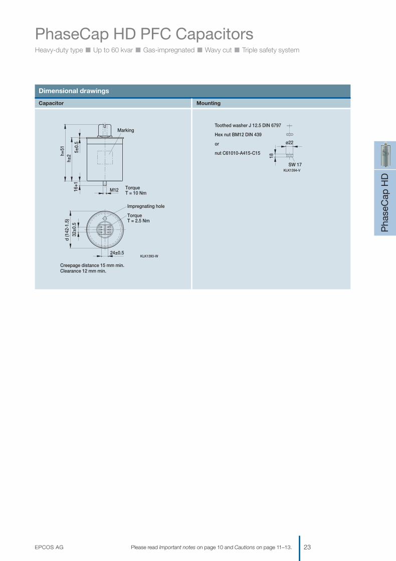
Dimensional drawings
Capacitor Mounting
KLK1394-V
Hex nut BM12 DIN 439
or
nut C61010-A415-C15
Toothed washer J 12.5 DIN 6797
18
SW 17
ø22
KLK1393-W
5±0.
516
+1
M12
32±0
.5
24±0.5
Marking
TorqueT = 10 Nm
Impregnating hole
TorqueT = 2.5 Nm
Creepage distance 15 mm min.Clearance 12 mm min.
h+51
h±2
d (1
42-1
.5)
1201070039_PFC_Katalog_07.qxd 14.08.2007 16:02 Uhr Seite 23

WindCap PFC CapacitorsFor PFC in wind turbines n 690 V grids n Harmonic filtering applications
Win
dC
ap
24 EPCOS AGPlease read Important notes on page 10 and Cautions on page 11–13.
GeneralWindCap heavy-duty AC capacitorsin cylindrical aluminum cases havebeen designed for power factor cor-rection and harmonics filtering inwind turbine and industrial applica-tions with 690 V requirements.The WindCap series demonstratesexcellent performance in toughconditions. High reliability and low life cycle cost are achieved by a mean life expectancy of up to 130000 hours. Wind turbine generators have a power factor < 1,meaning that producers have to addpower factor correction to improveperformance. WindCap capacitorsprovide relief from reactive powerand reduce ohmic losses in trans-
formers, supply cables and otherelectrical distribution equipment.
Applicationsn Wind turbine generator applicationsn Industrial applications with distorted
electrical networksn Harmonic filteringn For 690 /800 V grids
FeaturesElectricaln Low lossesn High pulse current withstand
capability (up to 300 · IR)n Corona-freeMechanical and maintenancen Reduced mounting costsn Any mounting positionn Maintenance-free
Safetyn Self-healingn Overpressure disconnectorn Touch-proof terminals n Long-term approved
MKK AC design & technologyEnvironmentaln Dry design, inert gasn No oil leakage
The compact WindCap capacitor is a self-healing, metalized polypro-pylene film capacitor using MKKtechnology with self-healing prop-erties. The current-carrying metallayer (electrode) is vapor-depositedonto one side of the film.
Compact design – low height,weight and volume
Three electrically separate capacitorelements are wound concentrically ina single operation onto an insulatedmetal core tube, which guaranteesexcellent winding precision. Theelectrodes are connected by metalspraying the face ends of the wind-ing elements.
The capacitor elements are deltaconnected to minimize losses. Thecompact MKK winding elements arehoused in a cylindrical aluminumcase and hermetically sealed by apress-rolled metal lid.
Triple safety system
n Dry technology: instead of aliquid impregnating agent, the ca-pacitor is filled with gas. So thereis no risk of leaking oil.
n Self-healing: the capacitor repairsitself after overload (to IEC 60831).
n Overpressure disconnector: referto page 9.
Innovative and reliable SIGUTconnection technology
SIGUT terminals ensure reliable andstraightforward connection, even in aparallel capacitor circuit, with bene-fits like:
n simplified parallel connectionn protection against electric shock
hazard (IP20 to VDE 0106 part100)
n separate connection of dischargeresistors
n clamping device to preventloosening of screws
n cable cross-sections up to 16 mm2
n max. 50 A total RMS current
Life expectancy of up to 130000operating hours
After a long drying phase undervacuum to eliminate moisture fromthe active element, the capacitoris impregnated. The case is filled withinert gas and sealed. Then routinetests are performed for gas leakage.
This production process helps toavoid oxidation and partial dis-charges (corona effect), promotingcapacitance stability over a longperiod, an essential in detuned PFC.
High inrush current withstandcapability is crucial
Capacitors used for power factorcorrection undergo a lot of switchingoperations. The high inrush currentsthat go along with this must be han-dled without degrading useful life.The pulse strength of this technologycomes in particular from the en-larged, sensitive contact area (im-proved metal spraying). The break-through came with a Siemens patentcalled the wavy cut, plus heavy-edgefilm design. WindCap capacitors canhandle inrush currents of up to 300times rated current (max. 5 000switching operations p.a. accordingIEC 60831 standard).
1201070039_PFC_Katalog_07.qxd 14.08.2007 16:02 Uhr Seite 24

WindCap PFC CapacitorsFor PFC in wind turbines n 690 V grids n Harmonic filtering applications
Win
dC
ap
EPCOS AG 25Please read Important notes on page 10 and Cautions on page 11–13.
Technical data and limit values
Standards IEC 60831-1+2, EN 60831-1+2, UL 810 5th edition
Overvoltage Vmax VR + 10% (up to 8 h daily) / VR + 15% (up to 30 min daily) /VR + 20% (up to 5 min daily) / VR + 30% (up to 1 min daily)
Overcurrent Imax up to 1.3 · IR (up to 1.5 · IR including combined effects of harmonics, overvoltages and capacitance tolerance)
Inrush current IS up to 300 · IR
Losses:– Dielectric < 0.2 W/kvar– Total* < 0.4 W/kvar
Rated frequency f 50 /60 Hz
Capacitance tolerance –5% / +10%
Test voltage, terminal / terminal VTT 2.15 · VR1, AC, 10 s
Test voltage, terminal /case VTC 6000 VAC, 10 s
Mean life expectancy t LD(Co) up to 130000 h
Ambient temperature –40/D; max. temp. 55 °C; max. mean 24 h = 45 °C; max. mean 1 year = 35 °C; lowest temperature = –25 °C
Cooling natural or forced
Humidity Hrel max. 95%
Altitude max. 4000 m above sea level
Mounting position random
Mounting and grounding threaded M12 stud on bottom of case
Safety dry technology, overpressure disconnector, self-healing, maximum allowed fault current 10000 A in accordance with UL 810 standard
Discharge resistors discharge module included
Case extruded aluminum can
Enclosure IP20, indoor mounting (optionally IP54)
Dielectric polypropylene film
Impregnation inert gas, Nitrogen (N2)
Terminals SIGUT terminal strip with electric shock protection (IP20), (VDE 0106part 100), max. 16 mm2 cable cross-section, max. current 50 A
Certification cUL file # E238746
Number of switching operations max. 5000 switchings per year according to IEC 60831-1+/2
* Without discharge resistor
1201070039_PFC_Katalog_07.qxd 14.08.2007 16:02 Uhr Seite 25

WindCap PFC CapacitorsFor PFC in wind turbines n 690 V grids n Harmonic filtering applications
Win
dC
ap
26 EPCOS AGPlease read Important notes on page 10 and Cautions on page 11–13.
Three-phase capacitors
Customized products available upon request. Minimum order quantity 200 pieces.
1) Packing units for capacitors equal minimum order quantity. Orders will be rounded up to packing unit or multiple thereof.
Type 50 Hz 60 Hz CR d x h Weight Ordering code Packingunit1)
Output IR Output IRkvar A kvar A μF mm kg
Rated voltage 690 VAC, 50 /60 Hz, delta connection
MKK690-D-5-11 5.0 4.2 6 5.0 3 · 11 121 x 164 1.3 B25668A6336A375 6
MKK690-D-10-11 10.0 8.4 12 10.1 3 · 23 121 x 164 1.4 B25668A6676A375 6
MKK690-D-12.5-11 12.5 10.5 15 12.6 3 · 28 121 x 164 1.5 B25668A6836A375 6
MKK690-D-15-11 15.0 12.6 18 15.1 3 · 34 121 x 164 1.5 B25668A6107A375 6
MKK690-D-20.8-11 20.8 17.5 25 21.0 3 · 47 142 x 200 2.0 B25668A6137A375 4
MKK690-D-25-11 25.0 21.0 30 25.1 3 · 56 142 x 200 2.2 B25668A6167A375 4
Rated voltage 765 VAC, 50 /60 Hz, delta connection
MKK765-D-30-11 30 23 36 28 3 · 55 142 x 200 2.4 B25668A7167J375 4
Rated voltage 800 VAC, 50 /60 Hz, delta connection
MKK800-D-5-11 5.0 3.6 6 4.3 3 · 8 121 x 164 1.2 B25668A7246A375 6
MKK800-D-10-11 10.0 7.2 12 8.7 3 · 17 121 x 164 1.3 B25668A7496A375 6
MKK800-D-12.5-11 12.5 9.0 15 11.0 3 · 21 121 x 164 1.4 B25668A7626A375 6
MKK800-D-15-11 15.0 11.0 18 13.0 3 · 25 121 x 164 1.5 B25668A7746A375 6
MKK800-D-20-11 20.0 14.5 24 17.3 3 · 33 142 x 200 2.0 B25668A7996A375 4
MKK800-D-25-11 25.0 18.0 30 22.0 3 · 41 142 x 200 2.3 B25668A7127A375 4
MKK800-D-28-11 28.0 20.0 33 24.0 3 · 46 142 x 200 2.4 B25668A7137A375 4
Plastic protective case for capacitor
For Degree l1 x h l3 l2 Weight Ordering codecapacitor diameter of protectionmm mm mm mm kg
121 x 164 IP54 134 x 243 177 110 0.3 B44066X9122A000
121 x 200 IP54 154 x 280 186 130.5 0.6 B44066X9142A000
142 x 200 IP54 154 x 280 186 130.5 0.6 B44066X9142A000
Plastic protective terminal cover
For For For cable Ø d1 Ø d2 Ordering codecapacitor diameter cable glandmm mm mm mm
121 x 164 PG 13.5 9–13 116 125 B44066K1211
121 x 200 PG 16 10–14 116 125 B44066K1212
142 x 200 PG 21 14–18 137 145 B44066K1421
Protective terminal cover Protective case for capacitor
1201070039_PFC_Katalog_07.qxd 14.08.2007 16:02 Uhr Seite 26

WindCap PFC CapacitorsFor PFC in wind turbines n 690 V grids n Harmonic filtering applications
Win
dC
ap
EPCOS AG 27Please read Important notes on page 10 and Cautions on page 11–13.
Dimensional drawings
Capacitor Protective case for capacitor
KLK1393-M
5±0.
516
+1
M12
19.6
±0.5
16.8±0.5
Marking
TorqueT = 10 Nm
Impregnating hole
TorqueT = 1.2 Nm
Creepage distance 12.7 mm min.Clearance 9.6 mm min.
h+40
d±1
h±2
KLK1394-V
Hex nut BM12 DIN 439
or
nut C61010-A415-C15
Toothed washer J 12.5 DIN 6797
18
SW 17
ø22
KLK1645-L-E
ød1
ød2
821
1)54
Cable gland
KLK1392-E
68.5
15.5 ø8
ø24ø27
h±3
±1 ±1
177
1 2
3
Mounting Protective cover for terminal
Overpressure disconnector (tear-off fuse)
1) Perforation for second cable gland
Compact windingwith C1,2,3
Connected
Detail A Detail B
DisconnectedOverpressure tear-off fuse
Terminal block
1201070039_PFC_Katalog_07.qxd 14.08.2007 16:02 Uhr Seite 27

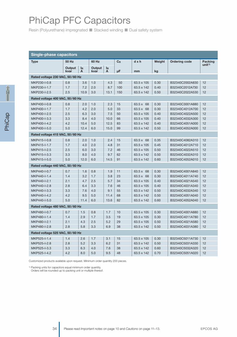
PhiCap PFC CapacitorsResin (Polyurethane) impregnated n Stacked winding n Dual safety system
The PhiCap is a self-healing, metal-ized polypropylene film capacitor.The current-carrying AlZn metal layeris vapor-deposited onto one side ofthe film.
Compact design – low weightand small volume
The entire three-phase capacitor iscomposed of three single-phase ele-ment stacks. The electrodes areconnected by metal spraying theface ends of the winding elements. The winding elements are encapsu-lated in a cylindrical aluminum caseand hermetically sealed either by apress-rolled metal lid or plastic diskwith fast-on terminals.
Dual safety system
n Self-healing: the capacitor repairsitself after overload (to IEC 60831).Self-healing capability preventspermanent dielectric breakdownin case of sporadic voltagesurges, overcurrent or overtem-perature (to IEC 60831).
n Overpressure disconnector: referto page 9.
Connection technology
n SIGUT block-type terminal forB32344 series: IP20, innovativeclamping system.
n Fast-on terminals for B32340 andB32343 series.
n Discharge resistors are includedin shipment.
PhiCap capacitor selection
To specify and select capacitors forPFC, several factors affecting theperformance and the expecteduseful life of the capacitors must beconsidered.n Voltagen Harmonicsn Temperature n Total RMS currentn Inrush current / switching
operations
Permanent overvoltage shortensthe useful life of a capacitor. The ca-pacitor’s rated voltage must be equalor higher than the operating voltageof the circuit to which it is connected.
Harmonics produce overvoltageand overcurrent on the capacitorsthemselves. If the total harmonicsdistortion level for voltage (THD-V)e.g. exceeds 5%, serious damage tothe installation may be caused by theresonance of the circuit.
In such cases usage of series re-actors (detuning) is recommended.
Operation of the capacitors abovethe upper category temperature lev-el will accelerate degradation of thedielectric and shorten the capaci-tor’s useful life.
By keeping min. 20 mm spacing andPhiCap capacitors mounted in up-right position, better thermal condi-tions will ensure best performanceand a longer useful life.
Residual voltage should not exceed10% of rated voltage for re-switch-ing capacitors. During the chargingperiod of the capacitors the current isvery high – if they are connected inautomatic capacitor banks, it is verylikely that discharged capacitors areconnected to charged ones alreadyconnected to the grid. In such casesthe maximum permissible currentpeak reaches values up to 150 · IR.
During the switching process ther-mal and electrodynamic stresses are developed caused by transientovercurrents of high amplitude andfrequency and may damage thesystem. Capacitor contactors withinrush current limiting resistors or series-inductance (e.g. detunedharmonic filter) will avoid excessivetransient currents.
Phi
Cap
28 EPCOS AGPlease read Important notes on page 10 and Cautions on page 11–13.
GeneralPhiCaps are a tried and testedseries of MKP (metalized polypro-pylene) capacitors from EPCOSwhich have been used for PFCapplications for more than 15 years.
The power range varies from 0.5 to30.0 kvar and 0.7 to 6.0 kvar persingle capacitor can, depending on a three-phase or single-phasecapacitor design. The PhiCap ca-pacitor is especially intended forpower factor correction in industrialand semi-industrial applications.The capacitors are manufacturedusing metalized polypropylene filmas the dielectric and housed in acylindrical aluminum case.
Applicationsn Power factor correction (PFC)n Automatic capacitor banksn Fixed PFC applications, e.g.
motor compensationn Detuned PFC systems
FeaturesElectricaln Up to 30 kvar per case for
three-phase applicationsn Up to 6 kvar per case for
single-phase applicationsn Long life expectancy of up to
100000 hoursn High pulse current withstand
capability (up to 200 · IR)
Mechanical and maintenancen Reduced mounting
costs, easy installation and connection
n Low weight and compact volume
n Maintenance-freeSafetyn Self-healingn Overpressure disconnectorn Touch-proof terminal
1201070039_PFC_Katalog_07.qxd 14.08.2007 16:02 Uhr Seite 28

PhiCap PFC CapacitorsResin (Polyurethane) impregnated n Stacked winding n Dual safety system
Life expectancy of up to 100 000operating hours
After a long drying phase to eliminatemoisture from the active element, thecapacitor is impregnated. The caseis filled with biodegradable soft resin.
This production process helps toavoid oxidation and partial dis-charges (corona effect), promotingcapacitance stability over a longperiod, an essential in detuned PFC.
High inrush current withstandcapability is crucial
Capacitors used for power factorcorrection undergo a lot of switchingoperations. The high inrush currentsthat go along with this must be han-dled without degrading useful life.The pulse strength of this technologycomes in particular from the en-larged, sensitive contact area (im-proved metal spraying).
PhiCap capacitors can handle inrushcurrents of up to 200 times rated cur-rent (max. 5 000 switching opera-tions p.a. according to IEC 60831standard).
Phi
Cap
EPCOS AG 29Please read Important notes on page 10 and Cautions on page 11–13.
Active power meter Apparentpower
Capacitor forcompensation
Reactivepower meter
GridP
SQ
Power factor improvement
Overpressure disconnector
Detail A
Detail B
Double fast-on terminal Disconnected
WindingC 1, 2, 3
Connected
1201070039_PFC_Katalog_07.qxd 14.08.2007 16:02 Uhr Seite 29

PhiCap PFC CapacitorsResin (Polyurethane) impregnated n Stacked winding n Dual safety system
Phi
Cap
30 EPCOS AGPlease read Important notes on page 10 and Cautions on page 11–13.
Technical data and limit values
Standards IEC 60831-1+2, IS: 13340/41
Overvoltage Vmax VR + 10% (up to 8 h daily) / VR + 15% (up to 30 min daily) /VR + 20% (up to 5 min daily) / VR + 30% (up to 1 min daily)
Overcurrent Imax up to 1.3 · IR (up to 1.5 · IR including combined effects of harmonics, overvoltages and capacitance)
Inrush current IS up to 200 · IR
Losses:– Dielectric < 0.2 W/kvar– Total* < 0.45 W/kvar
Rated frequency f 50 /60 Hz
Capacitance tolerance –5% /10%
Test voltage, terminal / terminal VTT 2.15 · VR, AC, 2 s
Test voltage, terminal /case VTC 3000 VAC, 10 s
Mean life expectancy t LD(Co) up to 100000 h
Ambient temperature –25/D; max. temp. 55 °C; max. mean 24 h = 45 °C; max. mean 1 year = 35 °C; lowest temperature = –25 °C
Cooling natural or forced
Humidity Hrel max. 95%
Altitude max. 4000 m above sea level
Mounting position upright
Mounting and grounding threaded M12 (10 Nm) for case size diam. > 53 mmM8 (4 Nm) for case size diam. ≤ 53 mm
Safety Self-healing technology, overpressure disconnector, maximum allowed fault current 10000 A in accordance with UL 810 standard
Discharge resistors discharge module included
Case extruded aluminum can
Enclosure IP20, indoor mounting (optional IP54)
Dielectric polypropylene film
Impregnation biodegradable soft resin
Terminals SIGUT screw terminals for B32344 series, max. current 60 A,max. 16 mm2 cable cross-section, fast-on terminals for B32340 and B32343 series
Number of switching operations max. 5000 switchings per year according to IEC 60831-1+/2
* Without discharge resistor
1201070039_PFC_Katalog_07.qxd 14.08.2007 16:02 Uhr Seite 30

PhiCap PFC CapacitorsResin (Polyurethane) impregnated n Stacked winding n Dual safety system
Phi
Cap
EPCOS AG 31Please read Important notes on page 10 and Cautions on page 11–13.
Three-phase capacitors
Customized products available upon request. Minimum order quantity 200 pieces.
1) Packing units for capacitors equal minimum order quantity. Orders will be rounded up to packing unit or multiple thereof.
Type 50 Hz 60 Hz CR d x h Weight Ordering code Packingunit1)
Output IR Output IRkvar A kvar A μF mm kg
Rated voltage 230 VAC, 50 /60 Hz, delta connection
MKP230-D-0.5 0.5 1.3 0.6 1.6 3 · 10 53 x 114 0.3 B32343C2002A530 12
MKP230-D-0.7 0.7 1.9 0.9 2.3 3 · 15 53 x 114 0.3 B32343C2002A730 12
MKP230-D-1.0 1.0 2.5 1.2 3.0 3 · 20 63.5 x 129 0.3 B32343C2012A030 12
MKP230-D-1.5 1.5 3.8 1.8 4.6 3 · 30 63.5 x 129 0.4 B32343C2012A530 12
MKP230-D-2.0 2.0 5.0 2.5 6.0 3 · 42 79.5 x 138 0.4 B32344D2022A030 6
MKP230-D-2.5 2.5 6.3 3.0 7.5 3 · 50 79.5 x 138 0.4 B32344D2022A530 6
MKP230-D-5.0 5.0 12.6 6.0 15.1 3 · 100 79.5 x 198 0.6 B32344D2052A030 6
MKP230-D-7.5 7.5 18.8 9.0 22.6 3 · 150 89.5 x 198 0.8 B32344D2072A530 4
MKP230-D-10.0 10.0 25.1 12.0 30.2 3 · 200 89.5 x 273 1.2 B32344D2102A030 4
MKP230-D-12.5 12.5 31.4 15.0 37.7 3 · 250 89.5 x 348 1.5 B32344D2122A530 4
MKP230-D-15.0 15.0 37.7 – – 3 · 300 89.5 x 348 1.5 B32344D2152A030 4
Rated voltage 400 VAC, 50 /60 Hz, delta connection
MKP400-D-1.0 1.0 1.4 1.2 1.7 3 · 7 53 x 114 0.3 B32343C4012A000 12
MKP400-D-1.5 1.5 2.2 1.8 2.6 3 · 10 53 x 114 0.3 B32343C4012A500 12
MKP400-D-2.0 2.0 2.9 2.4 3.5 3 · 13 63.5 x 129 0.4 B32343C4022A000 12
MKP400-D-2.5 2.5 3.6 3.0 4.3 3 · 17 63.5 x 129 0.4 B32343C4022A500 12
MKP400-D-5.0 5.0 7.2 6.0 8.6 3 · 33 63.5 x 129 0.4 B32343C4052A000 12
MKP400-D-6.3 6.3 9.1 7.5 11.0 3 · 42 79.5 x 160 0.5 B32344D4071A500 6
MKP400-D-7.5 7.5 10.8 9.0 13.0 3 · 50 79.5 x 160 0.5 B32344D4072A500 6
MKP400-D-8.3 8.3 12.0 10.0 14.5 3 · 55 79.5 x 160 0.5 B32344D4101A000 6
MKP400-D-10.0 10.0 14.5 12.0 17.3 3 · 67 79.5 x 198 0.6 B32344D4102A000 6
MKP400-D-12.5 12.5 18.1 15.0 21.7 3 · 83 89.5 x 198 0.8 B32344D4122A500 4
MKP400-D-15.0 15.0 21.7 18.0 26.0 3 · 100 89.5 x 198 0.8 B32344D4152A000 4
MKP400-D-16.7 16.7 24.1 20.0 28.9 3 · 111 89.5 x 198 0.8 B32344D4201A000 4
MKP400-D-20.0 20.0 28.9 24.0 34.7 3 · 133 89.5 x 273 1.1 B32344D4202A000 4
MKP400-D-25.0 25.0 36.1 – – 3 · 166 89.5 x 273 1.5 B32344D4252A000 4
Rated voltage 415 VAC, 50 /60 Hz, delta connection
MKP415-D-1.0 1.0 1.4 1.2 1.6 3 · 6 53 x 114 0.3 B32343C4012A010 12
MKP415-D-1.5 1.5 2.1 1.8 2.4 3 · 9 53 x 114 0.3 B32343C4012A510 12
MKP415-D-2.0 2.0 2.8 2.4 3.4 3 · 12 53 x 114 0.4 B32343C4022A010 12
MKP415-D-2.5 2.5 3.5 3.0 4.2 3 · 15 63.5 x 129 0.4 B32343C4022A510 12
MKP415-D-5.0 5.0 7.0 6.0 8.4 3 · 31 63.5 x 154 0.4 B32343C4052A010 12
MKP415-D-6.3 6.3 8.8 7.5 10.6 3 · 39 79.5 x 160 0.5 B32344D4071A510 6
MKP415-D-7.5 7.5 10.4 9.0 12.5 3 · 46 79.5 x 198 0.6 B32344D4072A510 6
MKP415-D-10.0 10.0 13.9 12.0 16.7 3 · 62 79.5 x 198 0.6 B32344D4102A010 6
MKP415-D-12.5 12.5 17.4 15.0 20.9 3 · 77 89.5 x 198 0.8 B32344D4122A510 4
MKP415-D-15.0 15.0 20.9 18.0 25.1 3 · 92 89.5 x 273 1.2 B32344D4152A010 4
MKP415-D-20.0 20.0 27.9 24.0 33.4 3 · 123 89.5 x 273 1.2 B32344D4202A010 4
MKP415-D-25.0 25.0 34.8 – – 3 · 154 89.5 x 348 1.5 B32344D4252A010 4
Rated voltage 440 VAC, 50 /60 Hz, delta connection
MKP440-D-0.9 0.9 1.2 1.0 1.3 3 · 5 53 x 114 0.3 B32343C4011A040 12
MKP440-D-1.0 1.0 1.3 1.2 1.6 3 · 6 53 x 114 0.3 B32343C4012A040 12
MKP440-D-1.2 1.2 1.6 1.5 2.0 3 · 7 53 x 114 0.3 B32343C4011A540 12
1201070039_PFC_Katalog_07.qxd 14.08.2007 16:02 Uhr Seite 31

PhiCap PFC CapacitorsResin (Polyurethane) impregnated n Stacked winding n Dual safety system
Phi
Cap
32 EPCOS AGPlease read Important notes on page 10 and Cautions on page 11–13.
Three-phase capacitors
Customized products available upon request. Minimum order quantity 200 pieces.
1) Packing units for capacitors equal minimum order quantity. Orders will be rounded up to packing unit or multiple thereof.
Type 50 Hz 60 Hz CR d x h Weight Ordering code Packingunit1)
Output IR Output IRkvar A kvar A μF mm kg
Rated voltage 440 VAC, 50 /60 Hz, delta connection
MKP440-D-1.5 1.5 2.0 1.8 2.3 3 · 8 53 x 114 0.3 B32343C4012A540 12
MKP440-D-2.1 2.1 2.7 2.5 3.3 3 · 11 53 x 114 0.4 B32343C4021A540 12
MKP440-D-2.5 2.5 3.3 3.0 3.9 3 · 13 63.5 x 129 0.3 B32343C4022A540 12
MKP440-D-4.2 4.2 5.5 5.0 6.6 3 · 23 63.5 x 129 0.4 B32343C4051A040 12
MKP440-D-5.0 5.0 6.5 6.0 7.8 3 · 27 63.5 x 154 0.5 B32343C4052A040 12
MKP440-D-6.3 6.3 8.3 7.5 9.9 3 · 34 79.5 x 160 0.5 B32344D4071A540 6
MKP440-D-7.5 7.5 9.9 9.0 11.8 3 · 41 79.5 x 160 0.5 B32344D4072A540 6
MKP440-D-8.3 8.3 10.9 10.0 13.1 3 · 46 79.5 x 198 0.6 B32344D4101A040 6
MKP440-D-10.0 10.0 13.1 12.0 15.8 3 · 55 79.5 x 198 0.6 B32344D4102A040 6
MKP440-D-10.4 10.4 13.7 12.5 16.4 3 · 57 79.5 x 198 0.6 B32344D4121A540 6
MKP440-D-12.5 12.5 16.4 15.0 19.7 3 · 69 89.5 x 198 0.8 B32344D4151A040 4
MKP440-D-15.0 15.0 19.7 18.0 23.6 3 · 82 89.5 x 273 1.2 B32344D4152A040 4
MKP440-D-16.7 16.7 21.9 20.0 26.3 3 · 92 89.5 x 273 1.2 B32344D4201A040 4
MKP440-D-20.8 20.8 27.3 25.0 32.8 3 · 114 89.5 x 273 1.2 B32344D4251A040 4
MKP440-D-25.0 25.0 32.8 – – 3 · 138 89.5 x 348 1.5 B32344D4252A040 4
MKP440-D-28.0 28.0 36.8 – – 3 · 154 89.5 x 348 1.5 B32344D4282A040 4
Rated voltage 480 VAC, 50 /60 Hz, delta connection
MKP480-D-1.5 1.5 1.8 1.8 2.2 3 · 7 63.5 x 129 0.4 B32343C4012A580 12
MKP480-D-2.0 2.0 2.4 2.4 2.9 3 · 9 63.5 x 129 0.4 B32343C4022A080 12
MKP480-D-2.5 2.5 3.0 3.0 3.6 3 · 11 63.5 x 129 0.4 B32343C4022A580 12
MKP480-D-4.2 4.2 5.1 5.0 6.1 3 · 19 63.5 x 154 0.5 B32343C4051A080 6
MKP480-D-5.0 5.0 6.0 6.0 7.2 3 · 23 79.5 x 160 0.5 B32344D4052A080 6
MKP480-D-6.3 6.3 7.6 7.6 9.1 3 · 29 79.5 x 160 0.5 B32344D4071A580 6
MKP480-D-7.5 7.5 9.0 9.0 10.8 3 · 35 79.5 x 198 0.6 B32344D4072A580 6
MKP480-D-8.3 8.3 10.0 10.0 12.0 3 · 38 79.5 x 198 0.6 B32344D4101A080 6
MKP480-D-10.4 10.4 12.5 12.5 15.0 3 · 48 89.5 x 198 0.8 B32344D4121A580 4
MKP480-D-12.5 12.5 15.1 15.0 18.1 3 · 58 89.5 x 198 0.8 B32344D4151A080 4
MKP480-D-15.0 15.0 18.1 18.0 21.7 3 · 69 89.5 x 273 1.2 B32344D4152A080 4
MKP480-D-16.7 16.7 20.1 20.0 24.1 3 · 77 89.5 x 273 1.2 B32344D4162A780 4
MKP480-D-20.8 20.8 25.0 25.0 30.1 3 · 96 89.5 x 273 1.2 B32344D4202A080 4
MKP480-D-25.0 25.0 30.1 30.0 36.1 3 · 115 89.5 x 348 1.5 B32344D4252A080 4
MKP480-D-30.0 30.0 36.1 – – 3 · 138 89.5 x 348 1.5 B32344D4302A080 4
Rated voltage 525 VAC, 50 /60 Hz, delta connection
MKP525-D-1.0 1.0 1.1 1.2 1.3 3 · 4 53 x 114 0.3 B32343C5012A020 12
MKP525-D-1.5 1.5 1.6 1.8 2.0 3 · 6 53 x 114 0.3 B32343C5012A520 12
MKP525-D-2.0 2.0 2.2 2.4 2.6 3 · 8 63.5 x 129 0.4 B32343C5022A020 12
MKP525-D-2.5 2.5 2.7 2.7 3.0 3 · 9 63.5 x 129 0.4 B32343C5022A520 12
MKP525-D-5.0 5.0 5.5 6.0 6.6 3 · 19 79.5 x 160 0.3 B32344D5061A020 6
MKP525-D-6.3 6.3 6.9 7.6 8.3 3 · 24 79.5 x 160 0.5 B32344D5071A520 6
MKP525-D-8.3 8.3 9.1 10.0 11.0 3 · 32 79.5 x 198 0.6 B32344D5101A020 6
MKP525-D-10.4 10.4 11.5 12.5 13.7 3 · 40 89.5 x 198 0.8 B32344D5121A520 4
MKP525-D-12.5 12.5 13.8 15.0 16.5 3 · 48 89.5 x 273 1.2 B32344D5151A020 4
MKP525-D-16.6 16.6 18.3 20.0 21.9 3 · 64 89.5 x 273 1.2 B32344D5201A020 4
MKP525-D-20.8 20.8 22.9 25.0 27.5 3 · 80 89.5 x 348 1.5 B32344D5202A020 4
MKP525-D-25.0 25.0 27.5 30.0 33.0 3 · 96 89.5 x 348 1.5 B32344D5252A020 4
1201070039_PFC_Katalog_07.qxd 14.08.2007 16:02 Uhr Seite 32

PhiCap PFC CapacitorsResin (Polyurethane) impregnated n Stacked winding n Dual safety system
Phi
Cap
EPCOS AG 33Please read Important notes on page 10 and Cautions on page 11–13.
Dimensional drawings: three-phase capacitors
Capacitor B32343 series
Capacitor B32344 series
KLK1670-2
11.8
±0.5
h±2
16 M12
d
Marking
Expa
nsio
n to
h±2
+α
FAST-ONTerminal 6.35 x 0.8
KLK1714-X-E
19.6
±0.5
M1216+1
h±3
d±1
Expa
nsio
n to
h±3
+α
Marking
SIGUT terminal
Torque T = 10 Nm
16.8±0.5Tightening torque = 1.2 Nm
h+40
1d
Creepage distance 10.5 mm (ø53) 10.0mm (ø63.5)
Clearance 13.0 mm (ø53) 16.5mm (ø63.5)
Diameter (ø) 53 mm63.5mm
Expansion α max. 12 mm
MountingM12 M8(ø 63.5 mm) (ø 53 mm)
Torque T=10 Nm T=4 Nm
Toothed J12.5 J8.0 washer DIN 6797 DIN 6797
Hex nut BM12 BM 8 DIN 439 DIN 439
Creepage distance 9.6 mm
Clearance 12.7 mm
Diameter d (ø) 79.5 mm/89.5mm
Diameter d1 (ø) 75.0 mm/85.0mm
Expansion α max. 13 mm
MountingM12 M5
Torque T=10 Nm T=2.5 Nm
Toothed washer J12.5 DIN 6797
Hex nut BM12 DIN 439
1201070039_PFC_Katalog_07.qxd 14.08.2007 16:02 Uhr Seite 33
PhiCap PFC CapacitorsResin (Polyurethane) impregnated n Stacked winding n Dual safety system
Phi
Cap
34 EPCOS AGPlease read Important notes on page 10 and Cautions on page 11–13.
Single-phase capacitors
Customized products available upon request. Minimum order quantity 200 pieces.
1) Packing units for capacitors equal minimum order quantity. Orders will be rounded up to packing unit or multiple thereof.
Type 50 Hz 60 Hz CR d x h Weight Ordering code Packingunit1)
Output IR Output IRkvar A kvar A μF mm kg
Rated voltage 230 VAC, 50 /60 Hz
MKP230-I-0.8 0.8 3.6 1.0 4.3 50 63.5 x 10⁵ 0.30 B32340C2002A830 12
MKP230-I-1.7 1.7 7.2 2.0 8.7 100 63.5 x 142 0.40 B32340C2012A730 12
MKP230-I-2.5 2.5 10.9 3.0 13.1 150 63.5 x 142 0.50 B32340C2022A530 12
Rated voltage 400 VAC, 50 /60 Hz
MKP400-I-0.8 0.8 2.0 1.0 2.3 15 63.5 x 68 0.30 B32340C3001A880 12
MKP400-I-1.7 1.7 4.2 2.0 5.0 33 63.5 x 68 0.30 B32340C4012A700 12
MKP400-I-2.5 2.5 6.3 3.0 7.5 50 63.5 x 10⁵ 0.40 B32340C4022A500 12
MKP400-I-3.3 3.3 8.4 4.0 10.0 66 63.5 x 10⁵ 0.40 B32340C4032A300 12
MKP400-I-4.2 4.2 10.4 5.0 12.5 83 63.5 x 142 0.40 B32340C4051A000 12
MKP400-I-5.0 5.0 12.4 6.0 15.0 99 63.5 x 142 0.50 B32340C4052A000 12
Rated voltage 415 VAC, 50 /60 Hz
MKP415-I-0.8 0.8 2.0 1.0 2.4 15 63.5 x 68 0.35 B32340C4082A310 12
MKP415-I-1.7 1.7 4.0 2.0 4.8 31 63.5 x 10⁵ 0.45 B32340C4012A710 12
MKP415-I-2.5 2.5 6.0 3.0 7.2 46 63.5 x 10⁵ 0.50 B32340C4022A510 12
MKP415-I-3.3 3.3 8.0 4.0 9.7 62 63.5 x 142 0.50 B32340C4032A310 12
MKP415-I-5.0 5.0 12.0 6.0 14.5 91 63.5 x 142 0.60 B32340C4052A010 12
Rated voltage 440 VAC, 50 /60 Hz
MKP440-I-0.7 0.7 1.6 0.8 1.9 11 63.5 x 68 0.30 B32340C4001A840 12
MKP440-I-1.4 1.4 3.2 1.7 3.8 23 63.5 x 68 0.30 B32340C4011A740 12
MKP440-I-2.1 2.1 4.7 2.5 5.7 34 63.5 x 10⁵ 0.40 B32340C4021A540 12
MKP440-I-2.8 2.8 6.4 3.3 7.6 46 63.5 x 10⁵ 0.40 B32340C4031A340 12
MKP440-I-3.3 3.3 7.6 4.0 9.1 55 63.5 x 142 0.50 B32340C4032A340 12
MKP440-I-4.2 4.2 9.5 5.0 11.4 68 63.5 x 142 0.50 B32340C4051A040 12
MKP440-I-5.0 5.0 11.4 6.0 13.6 82 63.5 x 142 0.60 B32340C4052A040 12
Rated voltage 480 VAC, 50 /60 Hz
MKP480-I-0.7 0.7 1.5 0.8 1.7 10 63.5 x 10⁵ 0.30 B32340C4001A880 12
MKP480-I-1.4 1.4 2.9 1.7 3.5 19 63.5 x 10⁵ 0.30 B32340C4011A780 12
MKP480-I-2.1 2.1 4.3 2.5 5.2 29 63.5 x 10⁵ 0.50 B32340C4021A580 12
MKP480-I-2.8 2.8 5.8 3.3 6.9 38 63.5 x 142 0.50 B32340C4031A380 12
Rated voltage 525 VAC, 50 /60 Hz
MKP525-I-1.4 1.4 2.6 1.7 3.1 15 63.5 x 10⁵ 0.30 B32340C5011A730 12
MKP525-I-2.8 2.8 5.2 3.3 6.2 31 63.5 x 142 0.50 B32340C5031A330 12
MKP525-I-3.3 3.3 6.3 4.0 7.6 38 63.5 x 142 0.60 B32340C5032A320 12
MKP525-I-4.2 4.2 8.0 5.0 9.5 48 63.5 x 142 0.70 B32340C5051A020 12
1201070039_PFC_Katalog_07.qxd 14.08.2007 16:02 Uhr Seite 34

PhiCap PFC CapacitorsResin (Polyurethane) impregnated n Stacked winding n Dual safety system
Phi
Cap
EPCOS AG 35Please read Important notes on page 10 and Cautions on page 11–13.
Dimensional drawings: single-phase capacitors
Capacitor B32340 series
Discharge resistors for B32340- and B32343-types Protective cover for terminal
KLK1669-Y
Terminal 6.35 x 0.8
13
h±2
16 M12
d±1
Marking
FAST-ON
Expa
nsio
n to
h±2
+α
Toothed washer DIN6797
Hex nut DIN439
Creepage distance 10.0 mm
Clearance 16.5mm
Diameter (ø) 63.5mm
Expansion α max. 12 mm
MountingM12
Torque T=10 Nm
Toothed washer J12.5 DIN 6797
Hex nut BM12 DIN 439
KLK1685-F
DischargeResistorSet
KLK1645-L-E
ød1
ød2
821
1)54
Cable gland
Ø in mm Ordering code
53 B44066K0530A000*
63.5 B44066K0635A000*
79.5 B44066K0795A000
89.5 B44066K0895A000
Discharge resistors pre-mounted for B32344D
1) Perforationfor second cable gland
* For B32340 andB32343 types (diameter 53 and 63.5 mm), terminalcovers with cableentry on top
1201070039_PFC_Katalog_07.qxd 14.08.2007 16:02 Uhr Seite 35

MKV PFC CapacitorsFor high ambient temperatures (up to +70 ºC) n High overcurrent capability
MK
V
36 EPCOS AGPlease read Important notes on page 10 and Cautions on page 11–13.
GeneralThe winding element of the MKVcapacitor consists of a dielectric ofpolypropylene film and an electrodeof double-sided metalized paper.This winding construction achieveslow losses and a high pulse-currentwithstand capability. Oil is used for impregnation of the capacitor.The oil impregnation (due to thepaper film) enables good heat dissi-pation from the winding element to the aluminum can’s surface, thus preventing hot spots in thewinding element.The capacitor is designed to coverambient temperatures of up to+70 °C max.
Applicationsn Power factor correction to
improve the power quality– Applications with high
thermal loading – PFC systems dealing
with harmonic loadsn AC applications in industrial
electronics, e.g. high dv/dt n Tuned harmonic filter
FeaturesElectricaln Long life expectancy
(up to 150000 h)n Maximum pulse current
withstand capability (up to 300 · IR)
Mechanical and maintenancen Easy installation and connectionn Maintenance-freeSafetyn Self-healingn Overpressure disconnector
Three-phase capacitors
Type 50 Hz 60 Hz Imax RMS CR d x h Weight Ordering code Packingunit1)
Output IR Output IRkvar A kvar A A μF mm kg
Rated voltage 400 VAC, 50 /60 Hz, delta connection
MKV400-D-5-02 5.0 7.0 6.0 8.5 55 3 · 33 79.2 x 248 1.3 B25836B4996A305 2
MKV400-D-10-02 10.0 14.0 12.0 17.0 55 3 · 66 121.6 x 248 2.9 B25836B4197A305 2
MKV400-D-12.5-02 12.5 18.0 15.0 19.7 55 3 · 83 121.6 x 248 3.0 B25836B4247A305 2
MKV400-D-15-02 15.0 22.0 18.0 26.0 55 3 · 99 121.6 x 248 3.1 B25836B3297A305 2
Rated voltage 525 VAC, 50 /60 Hz, delta connection
MKV525-D-10-02 10.0 11.0 12.0 13.2 55 3 · 38 99.3 x 248 2.1 B25836B5117A305 2
MKV525-D-12.5-02 12.5 14.0 15.0 17.0 55 3 · 48 121.6 x 248 3.1 B25836B5147A305 2
Rated voltage 600 VAC, 50 /60 Hz, delta connection
MKV600-D-10.4-02 10.4 10.0 12.5 12.0 55 3 · 30 121.6 x 248 3.1 B25836B6926A305 2
Rated voltage 690 VAC, 50 /60 Hz, delta connection
MKV690-D-12.5-02 12.5 11.0 15.0 13.2 55 3 · 27 121.6 x 248 3.1 B25836B6836A305 2
1) Packing units for capacitors equal minimum order quantity.Orders will be rounded up to packing unit or multiple thereof.
1201070039_PFC_Katalog_07.qxd 14.08.2007 16:02 Uhr Seite 36

MKV PFC CapacitorsFor high ambient temperatures (up to +70 ºC) n High overcurrent capability
MK
V
EPCOS AG 37Please read Important notes on page 10 and Cautions on page 11–13.
Technical data and limit values
Standards IEC 60831-1+2, EN 60831-1+2, VDE 560-46+47, UL 810 5th edition
Overvoltage Vmax VR + 10% (up to 8 h daily) / VR + 15% (up to 30 min daily) /VR + 20% (up to 5 min daily) / VR + 30% (up to 1 min daily)
Overcurrent Imax up to 1.8 · IR (including combined effects of harmonics, overvoltages and capacitance tolerance)
Inrush current IS up to 300 · IR
Losses:– Dielectric < 0.2 W/kvar– Total* < 0.45 W/kvar
Rated frequency f 50 /60 Hz
Capacitance tolerance –5%/+10%
Test voltage, terminal / terminal VTT 2.15 · VR1, AC, 10 s
Test voltage, terminal /case VTC VR ≤ 660 V: 3000 VAC, 10 sVR ≤ 660 V: 6000 VAC, 10 s
Mean life expectancy t LD(Co) up to 150000 h
Ambient temperature max. temp. 70 °C; max. mean 24 h = 55 °C; max. mean 1 year = 45 °C; lowest temperature = –25 °C
Cooling natural or forced
Humidity Hrel max. 95%
Altitude max. 4000 m above sea level
Mounting position upright
Mounting and grounding threaded M12 stud on bottom of case
Safety overpressure disconnector, self-healing
Discharge resistors discharge module included
Case extruded aluminum can
Enclosure IP00, indoor mounting
Dielectric polypropylene film with paper as electrode carrier
Impregnation oil
Terminals SIGUT terminal strip with electric shock protection (IP20), (VDE 0106part 100), max. 16 mm2 cable cross-section, max. current 50 A
Number of switching operations max. 5000 switchings per year according to IEC 60831-1+/2
* Without discharge resistor
1201070039_PFC_Katalog_07.qxd 14.08.2007 16:02 Uhr Seite 37
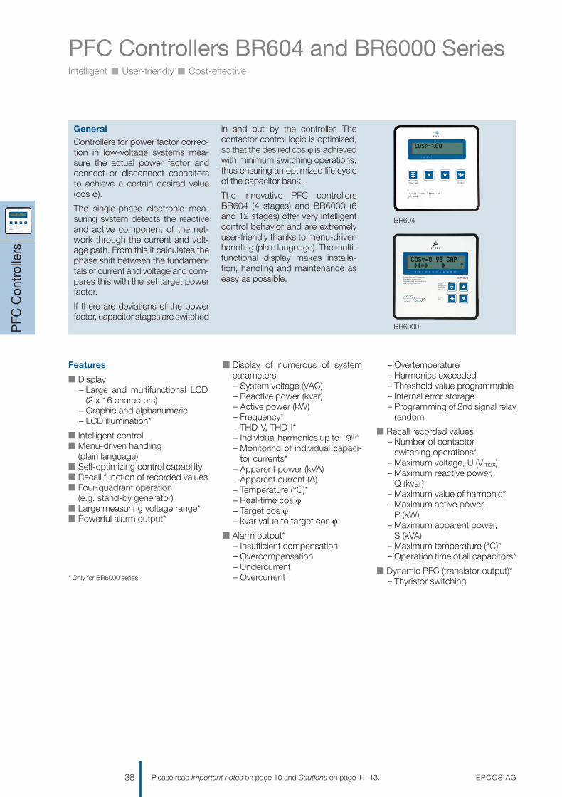
PFC Controllers BR604 and BR6000 SeriesIntelligent n User-friendly n Cost-effective
* Only for BR6000 series
PFC
Con
trol
lers
38 EPCOS AGPlease read Important notes on page 10 and Cautions on page 11–13.
GeneralControllers for power factor correc-tion in low-voltage systems mea-sure the actual power factor andconnect or disconnect capacitorsto achieve a certain desired value(cos ϕ).
The single-phase electronic mea-suring system detects the reactiveand active component of the net-work through the current and volt-age path. From this it calculates thephase shift between the fundamen-tals of current and voltage and com-pares this with the set target powerfactor.
If there are deviations of the powerfactor, capacitor stages are switched
in and out by the controller. Thecontactor control logic is optimized,so that the desired cos ϕ is achievedwith minimum switching operations,thus ensuring an optimized life cycleof the capacitor bank.
The innovative PFC controllersBR604 (4 stages) and BR6000 (6and 12 stages) offer very intelligentcontrol behavior and are extremelyuser-friendly thanks to menu-drivenhandling (plain language). The multi-functional display makes installa-tion, handling and maintenance aseasy as possible.
BR604
BR6000
Features
n Display– Large and multifunctional LCD
(2 x 16 characters)– Graphic and alphanumeric – LCD illumination*
n Intelligent controln Menu-driven handling
(plain language)n Self-optimizing control capability n Recall function of recorded valuesn Four-quadrant operation
(e.g. stand-by generator)n Large measuring voltage range*n Powerful alarm output*
n Display of numerous of systemparameters– System voltage (VAC)– Reactive power (kvar)– Active power (kW)– Frequency*– THD-V, THD-I*– Individual harmonics up to 19th*– Monitoring of individual capaci-
tor currents*– Apparent power (kVA)– Apparent current (A)– Temperature (°C)*– Real-time cos ϕ– Target cos ϕ– kvar value to target cos ϕ
n Alarm output*– Insufficient compensation– Overcompensation– Undercurrent– Overcurrent
– Overtemperature– Harmonics exceeded– Threshold value programmable– Internal error storage– Programming of 2nd signal relay
random
n Recall recorded values– Number of contactor
switching operations*– Maximum voltage, U (Vmax)– Maximum reactive power,
Q (kvar)– Maximum value of harmonic*– Maximum active power,
P (kW)– Maximum apparent power,
S (kVA)– Maximum temperature (°C)* – Operation time of all capacitors*
n Dynamic PFC (transistor output)*– Thyristor switching
1201070039_PFC_Katalog_07.qxd 14.08.2007 16:02 Uhr Seite 38

PFC Controllers BR604 and BR6000 SeriesIntelligent n User-friendly n Cost-effective
PFC
Con
trol
lers
EPCOS AG 39Please read Important notes on page 10 and Cautions on page 11–13.
Technical data BR6000 series BR604 series
Weight 1 kg 0.5 kg
Case panel-mounted instrument, panel-mounted instrument, 144 x 144 x 60 mm 100 x 100 x 40 mm(cut out 138 x 138 mm) (cut out 92 x 92 mm)
Ambient conditions
Overvoltage class III III
Pollution degree 2 2
Operating temperature –10 °C ... +70 °C –10 °C ... +70 °C
Storage temperature –20 °C ... +75 °C –20 °C ... +75 °C
Sensitivity to interference (industrial areas) EN 55082-2.1995 EN 55082-2.1995
Spurious radiation (residential areas) EN 55011 10.1997 EN 55011 10.1997
Safety guidelines EN 61010-1:2001 EN 61010-1:2001 IEC 61010-1:2001 IEC 61010-1:2001
Mounting position any any
Humidity class 15% to 95% without dew 15% to 95% without dew
Protection class Front plate IP54 according to IEC 60529 / DIN 40050 IP54 according to IEC 60529 / DIN 40050Rear IP20 according to IEC 60529 / DIN 40050 IP20 according to IEC 60529 / DIN 40050
Operation
Supply voltage 230 VAC, 50 and 60 Hz power lines 230 VAC, 50 and 60 Hz power lines
Target cos ϕ 0.8 ind.–0.8 cap. 0.8 ind.–0.8 cap.
Switching and discharge time range 1 – 1200 seconds 1 – 255 seconds
Number of control series 20 series preset + control series 23 series preset editor for free programming
Control modes series switching (LIFO), series switching (LIFO), circular switching (FIFO), circular switching (FIFO),self-optimized intelligent control mode self-optimized intelligent control mode
Measurement
Measurement voltage range 30 ... 300 VAC phase to neutral = supply voltage: 230 VAC (L-N)(i.e. 50 ... 525 V phase to phase)
Fundamental frequency 50 and 60 Hz 50 and 60 Hz
Measurement current (CT) x/1 and x/5 Ampere possible x/1 and x/5 Ampere possible
Minimum operating current 10/50 mA 10/50 mA
Maximum current 5.3 A (sinusoidal) 5.3 A (sinusoidal)
Zero voltage release < 15 ms < 15 ms
Switching outputs
Relay outputsNumber of relays 6 and 12 stages available 4 stages availableSwitching voltage /power max. 250 VAC, max. 1000 W max. 250 VAC, max. 1000 WExpected mechanical life > 30 x 106 switching operations > 30 x 106 switching operationsExpected electrical life > 5 x 10⁶ switching operations > 5 x 10⁶ switching operations
(load = 200 VA, cos ϕ = 0.4) (load = 200 VA, cos ϕ = 0.4)
Alarm relay potential-free contact (6 parameters) no
1201070039_PFC_Katalog_07.qxd 14.08.2007 16:02 Uhr Seite 39

PFC Controllers BR604 and BR6000 SeriesIntelligent n User-friendly n Cost-effective
PFC
Con
trol
lers
40 EPCOS AGPlease read Important notes on page 10 and Cautions on page 11–13.
BR6000T for dynamic powerfactor correction
The dynamic power factor controllerBR6000T represents the follow-ondevelopment of the BR6000 serieswith innovative ideas and a multitudeof functions.
It has been especially designed tocontrol thyristor modules for directswitching of power capacitors forpower factor correction (for example
TSM-LC or similar). By using a veryfast type of processor, it has beenpossible to obtain extremely shortswitching cycles, which can be usedfor dynamic power factor correction.
In addition to a switching time of <40 ms, the intelligent control princi-ple provides an extremely fast tuningtime by simultaneous switching ofseveral stages.
Individual parameters that can beedited allow optimized adjustment todifferent thyristor modules.
Another innovation is the possibilityof a simple coupling of two PFC con-trollers with one another (for examplecascading in case of two systemswith two inputs and one couplingswitch). This is possible without in-terface option.
Accessories: adapter for PFC controller BR6000
This adapter is used to align the PFCcontroller BR6000 to grids withoutneutral conductor. To achieve this, theinput of the adapter is connected to
the 3 phases of the grid, and theoutput is connected to the measur-ing voltage input of the controller.
The voltage at the measuring inputmust not exceed 525 V. At output“1/2 L1” half measuring voltage L-Nis disposable.
Adapter BR6000
Characteristics
Design compact form, all connections as screw type clamp
Mounting snap on top hat rail
Technical dataInput voltage grid without neutral max. 3 x 525 V
Output voltage 1 L1-N
Output voltage 2 1/2 L1-N(to use this output, a V-transformer ratio of 2 has to be programmed on the BR6000)
Protection necessary external according to cable cross-section
Max. ambient temperature –20 ... +55 °C
Dimensions height 76 mm, width 45 mm, depth 110 mm
Ordering codes
Type Voltage Output Alarm Switchover Interface Ordering code Packing50/60 Hz Relay Transistor output target unit
cos ϕ 1/2
BR604-R4 230 4 – no no no B44066R6004E230 24
BR6000-R6 230 6 – yes no no B44066R6006E230 24
BR6000-T6 230 – 6 yes no no B44066R6106E230 24
BR6000-R12 230 12 – yes no no B44066R6012E230 24
BR6000-T12 230 – 12 yes yes no B44066R6112E230 24
BR6000-R12/F 230 12 – yes yes no B44066R6212E230 24
BR6000-R12/S232* 230 12 – yes yes RS232 B44066R6312E230 24
BR6000-R12/S485 230 12 – yes yes RS485 B44066R6412E230 24
BR6000 Adapter B44066R9999E230
* Including Windows software
V Cautions: 1. Discharge time: Make sure that discharge time set in controller matches capacitor discharge time. See page 12.2. Number of switchings: LV PFC capacitors according to standard IEC 60831 are designed for up to 5000 switching operations.
Make sure that 5000 switching operations per year are not exceeded.3. Controller hunting must be avoided at any case!
1201070039_PFC_Katalog_07.qxd 14.08.2007 16:02 Uhr Seite 40

PFC Controllers BR604 and BR6000 SeriesIntelligent n User-friendly n Cost-effective
PFC
Con
trol
lers
EPCOS AG 41Please read Important notes on page 10 and Cautions on page 11–13.
PFC controller BR604
PFC controller BR6000
1201070039_PFC_Katalog_07.qxd 14.08.2007 16:02 Uhr Seite 41
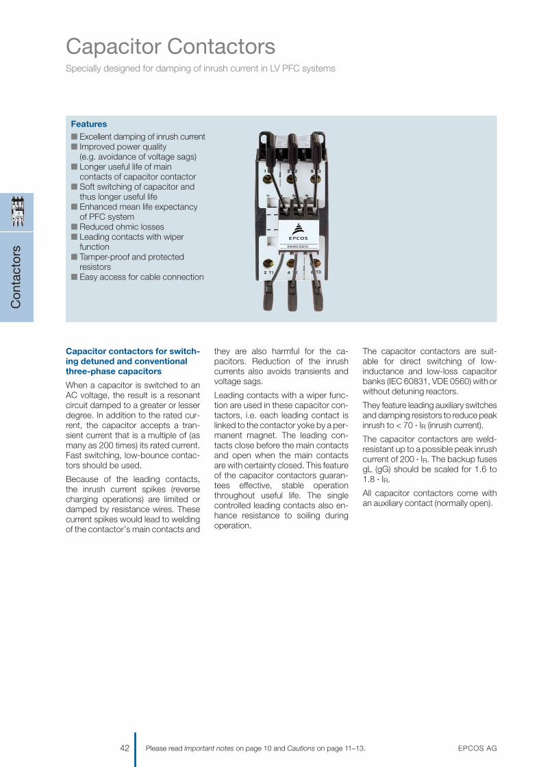
Capacitor ContactorsSpecially designed for damping of inrush current in LV PFC systems
Con
tact
ors
42 EPCOS AGPlease read Important notes on page 10 and Cautions on page 11–13.
Featuresn Excellent damping of inrush currentn Improved power quality
(e.g. avoidance of voltage sags)n Longer useful life of main
contacts of capacitor contactorn Soft switching of capacitor and
thus longer useful lifen Enhanced mean life expectancy
of PFC systemn Reduced ohmic lossesn Leading contacts with wiper
functionn Tamper-proof and protected
resistorsn Easy access for cable connection
Capacitor contactors for switch-ing detuned and conventionalthree-phase capacitors
When a capacitor is switched to anAC voltage, the result is a resonantcircuit damped to a greater or lesserdegree. In addition to the rated cur-rent, the capacitor accepts a tran-sient current that is a multiple of (asmany as 200 times) its rated current.Fast switching, low-bounce contac-tors should be used.
Because of the leading contacts, the inrush current spikes (reversecharging operations) are limited ordamped by resistance wires. Thesecurrent spikes would lead to weldingof the contactor’s main contacts and
they are also harmful for the ca-pacitors. Reduction of the inrushcurrents also avoids transients andvoltage sags.
Leading contacts with a wiper func-tion are used in these capacitor con-tactors, i.e. each leading contact islinked to the contactor yoke by a per-manent magnet. The leading con-tacts close before the main contactsand open when the main contactsare with certainty closed. This featureof the capacitor contactors guaran-tees effective, stable operationthroughout useful life. The singlecontrolled leading contacts also en-hance resistance to soiling duringoperation.
The capacitor contactors are suit-able for direct switching of low-inductance and low-loss capacitorbanks (IEC 60831, VDE 0560) with orwithout detuning reactors.
They feature leading auxiliary switchesand damping resistors to reduce peakinrush to < 70 · IR (inrush current).
The capacitor contactors are weld-resistant up to a possible peak inrushcurrent of 200 · IR. The backup fusesgL (gG) should be scaled for 1.6 to1.8 · IR.
All capacitor contactors come withan auxiliary contact (normally open).
1201070039_PFC_Katalog_07.qxd 14.08.2007 16:02 Uhr Seite 42

Capacitor ContactorsSpecially designed for damping of inrush current in LV PFC systems
Con
tact
ors
EPCOS AG 43Please read Important notes on page 10 and Cautions on page 11–13.
Technical data
Type B44066-…-J230/110Main contacts S1810 S2410 S3210 S5010 S6210 S7410
Rated insulation voltage VI VIS [VAC] 6902) 6902) 6902) 6902) 6902) 6902)
Admissible frequency of operation 1/h 120 120 120 120 120 80Contact life million 0.25 0.15 0.15 0.15 0.15 0.12
operations
Cable cross-sectionsolid or standard [mm2] 1.5–6 2.5–25 2.5–25 4–50 4–50 4–50
flexible [mm2] 1.5–4 2.5–16 2.5–16 10–35 10–35 10–35
flexible with multicore cable end [mm2] 1.5–4 2.5–16 2.5–16 6–35 6–35 6–35
Cables per clamp 2 1 1 1 1 1
Operating range of magnet coilsin multiples of control voltage VS 0.85–1.1 0.85–1.1 0.85–1.1 0.85–1.1 0.85–1.1 0.85–1.1
Auxiliary contacts1)
Rated insulation voltage VI VIS [VAC] 6902) 6902) 6902) 6902) 6902) 6902)
Rated current Ithat ambient temperaturemax. 40 °C Icoth [A] 16 10 10 10 10 10
max. 60 °C Icoth [A] 12 6 6 6 6 6
Utilization category AC15220 to 240 V Icoth [A] 12 3 3 3 3 3
380 to 440 V Icoth [A] 4 2 2 2 2 2
Short circuit protectionHighest fuse rating Icoth [A] 25 20 20 20 20 20slow, gL (gG)Auxiliary contacts1) NO /NC 1/0 1 /0 1 /0 1 /0 1 /0 1 /0
IEC 947-4-1, IEC 947-5-1, EN 60947-4-1, EN 60947-5-1, VDE 0660
1) Aux. contacts: NO = 1; NC = 0; for all contactor types2) Applies to networks with grounded star point, overvoltage category I to IV, pollution severity 3 (industrial standard),
Vimp = 6 kV. Values for other conditions on request.
Main technical parameters
Capacitor power at ambient temperature, voltage, 50 /60 Hz Current Weight Ordering code Packing380–400 V 415–440 V 660–690 V max. unit50 ºC 60 ºC 50 ºC 60 ºC 50 ºC 60 ºC 50 ºC 60 ºCkvar kvar kvar kvar kvar kvar A A kg
110 V coil
0–12.5 0–12.5 0 – 13 0 – 13 0 – 20 0 – 20 18 18 0.34 B44066S1810J110 48
10–20 10–20 10.5–22 10.5–22 17 – 33 17 – 33 28 28 0.6 B44066S2410J110 40
10–25 10–25 10.5–27 10.5–27 17 – 41 17 – 41 36 36 0.6 B44066S3210J110 40
20–50 20–50 23 – 53 23 – 53 36 – 82 36 – 82 72 72 1.1 B44066S6210J110 15
20–75 20–60 23 – 75 23 – 64 36–120 36–100 105 87 1.1 B44066S7410J110 15
230 V coil
0–12.5 0–12.5 0 – 13 0 – 13 0 – 20 0 – 20 18 18 0.34 B44066S1810J230 48
10–20 10–20 10.5–22 10.5–22 17 – 33 17 – 33 28 28 0.6 B44066S2410J230 40
10–25 10–25 10.5–27 10.5–27 17 – 41 17 – 41 36 36 0.6 B44066S3210J230 40
20–33.3 20–33.3 23 – 36 23 – 36 36 – 55 36 – 55 48 48 1.1 B44066S5010J230 15
20–50 20–50 23 – 53 23 – 53 36 – 82 36 – 82 72 72 1.1 B44066S6210J230 15
20–75 20–60 23 – 75 23 – 64 36–120 36–100 105 87 1.1 B44066S7410J230 15
1201070039_PFC_Katalog_07.qxd 14.08.2007 16:02 Uhr Seite 43

Capacitor ContactorsSpecially designed for damping of inrush current in LV PFC systems
Con
tact
ors
44 EPCOS AGPlease read Important notes on page 10 and Cautions on page 11–13.
Dimensional drawings
B44066S1810J230, B44066S1810J110
B44066S2410J230, B44066S3210J230, B44066S2410J110, B44066S3210J110
KLK1719-4
49-5
0
5945
35-36
ø5
M3.5
98
94
50
6.5
85
KLK1718-V
M5
ø4.5
606574
35
45 119.5
115.5
6.5
63
115
1201070039_PFC_Katalog_07.qxd 14.08.2007 16:02 Uhr Seite 44

Capacitor ContactorsSpecially designed for damping of inrush current in LV PFC systems
Con
tact
ors
EPCOS AG 45Please read Important notes on page 10 and Cautions on page 11–13.
Dimensional drawings
B44066S5010J230, B44066S6210J230, B44066S7410J230, B44066S6210J110, B44066S7410J110
Connection diagramm B44066S1810J230 and B44066S1810J110 with wires on the bottom only
KLK1717-M
M6
ø5.5
50
60
90100
110
7.5
68
124.5
128.5
145
KLK1694-E
1
2
3
4
5
6
A1
A2
L1 L2 L3
AUX
1201070039_PFC_Katalog_07.qxd 14.08.2007 16:02 Uhr Seite 45

Antiresonance Harmonic Filter Reactors
Rea
ctor
s
46 EPCOS AGPlease read Important notes on page 10 and Cautions on page 11–13.
Featuresn High harmonic loading capabilityn Very low lossesn High linearity to avoid choke tiltn Low noisen Convenient mountingn Long expected life timen Temperature protection
(NC contact)
General
Electrical energy is a significant pro-duction factor for industry, and itsefficient use should be a primaryobjective. Reducing the reactivecurrent component by PFC correc-tion helps to save energy.
The increasing use of modern powerelectronic apparatus (drives, uninter-ruptible power supplies, etc) pro-duces nonlinear current, influencesand loads the network with har-monics (line pollution).
The power factor correction or ca-pacitance of the power capacitorforms a resonant circuit in conjunc-tion with the feeding transformer.Experience shows that the self-res-onant frequency of this circuit istypically between 250 and 500 Hz,i.e. in the region of the 5th and 7thharmonics. Resonance can lead to the followingundesirable effects:
– overloading of capacitors,– overloading of transformers and
transmission equipment,– interference with metering and
control systems, computers andelectrical gear,
– resonance elevation, i.e. amplifi-cation of harmonics,
– voltage distortion.
These resonance phenomena canbe avoided by connecting capacitorsin series with filter reactors. Detunedsystems are scaled so that the self-resonant frequency is below thelowest line harmonic. The detunedPFC system is purely inductive seen by harmonics above this fre-quency. For the 50 Hz line frequency,the detuned system acts purelycapacitively, thus correcting the re-active power.
1201070039_PFC_Katalog_07.qxd 14.08.2007 16:02 Uhr Seite 46

Antiresonance Harmonic Filter Reactors
Rea
ctor
s
EPCOS AG 47Please read Important notes on page 10 and Cautions on page 11–13.
Technical data and limit values
Filter reactors
Harmonics* V3 = 0.5% VR (duty cycle = 100%)V5 = 6.0% VR (duty cycle = 100%)V7 = 5.0% VR (duty cycle = 100%)V11 = 3.5% VR (duty cycle = 100%)V13 = 3.0% VR (duty cycle = 100%)
Effective current Irms = ß®(I12+I32 ... I132)
Fundamental current I1 = 1.06 · IR (50 Hz or 60 Hz current of capacitor)
Temperature protection microswitch (NC)
Three-phase filter reactors to EN 61558 /VDE 0532 /EN 60289
Frequency 50 Hz or 60 Hz
Voltage 400, 440, 480 V
Output 10 … 100 kvar
Detuning 5.67%, 7%, 14%
Cooling natural
Ambient temperature 40 °C
Class of protection I
Enclosure IP00
Approval
* According to DIN ENV VV61000-2-2
* Total max. losses, considering max. specified overvoltage and harmonic currents
Characteristics
Power Δ Inductance Irms Losses* Weight Drawing Terminal Ordering code Packingcapacitance (Ieff) number unit
kvar 3 · μF mH A W kg
Rated voltage V = 400 V, f = 50 Hz, p = 5.67% (fr = 210 Hz) / Linearity: L ≥ 0.95 · LR for current up to 2.08 · I1
10 62 3.06 18.5 64 6.4 1c 10 mm2 Kl. B44066D5010S400 40
12.5 78 2.45 23.0 89 8.4 1d 10 mm2 Kl. B44066D5012S400 40
20 125 1.53 36.9 100 13 1e 10 mm2 Kl. B44066D5020S400 18
25 156 1.22 46.1 130 17 1f 10 mm2 Kl. B44066D5025S400 18
40 250 0.765 73.7 220 23 3b M6 Al-flat B44066D5040S400 18
50 312 0.612 92.1 290 31 3c M6 Al-flat B44066D5050S400 12
75 496 0.408 138.2 280 35 3c M8 Al-flat B44066D5075S400 12
100 625 0.306 183.8 390 47 3d M8 Al-flat B44066D5100S400 1
Rated voltage V = 400 V, f = 50 Hz, p = 7% (fr = 189 Hz) / Linearity: L ≥ 0.95 · LR for current up to 1.73 · I1
10 61 3.83 16.4 73 5.9 1c 10 mm2 Kl. B44066D7010S400 40
12.5 77 3.07 20.5 87 8.1 1d 10 mm2 Kl. B44066D7012S400 40
20 123 1.92 32.7 100 12 1e 10 mm2 Kl. B44066D7020S400 40
25 154 1.53 41.0 120 16 1f 10 mm2 Kl. B44066D7025S400 18
40 246 0.958 65.6 210 23 3b M6 Al-flat B44066D7040S400 18
50 308 0.766 81.9 210 24 3b M6 Al-flat B44066D7050S400 18
75 462 0.511 122.9 267 32 3c M8 Al-flat B44066D7075S400 12
100 617 0.383 164.2 370 46 3d M8 Al-flat B44066D7100S400 1
1201070039_PFC_Katalog_07.qxd 14.08.2007 16:02 Uhr Seite 47

Antiresonance Harmonic Filter Reactors
Rea
ctor
s
48 EPCOS AGPlease read Important notes on page 10 and Cautions on page 11–13.
* Total max. losses, considering max. specified overvoltage and harmonic currents
Characteristics
Power Δ Inductance Irms Losses* Weight Drawing Terminal Ordering code Packingcapacitance (Ieff) number unit
kvar 3 · μF mH A W kg
Rated voltage V = 400 V, f = 50 Hz, p = 14% (fr = 135 Hz) / Linearity: L ≥ 0.95 · LR for current up to 1.4 · I1
10 57 8.23 15.4 87 9.4 1d 10 mm2 Kl. B44066D1410S400 40
12.5 71 6.63 19.2 100 12 1e 10 mm2 Kl. B44066D1412S400 18
20 114 4.14 30.8 120 18 1f 10 mm2 Kl. B44066D1420S400 18
25 142 3.32 38.5 210 25 2a 10 mm2 Kl. B44066D1425S400 18
40 228 2.07 61.6 220 32 3c M6 Al-flat B44066D1440S400 1
50 285 1.66 76.9 340 34 3c M6 Al-flat B44066D1450S400 1
75 427 1.1 115.4 330 52 3d M8 Al-flat B44066D1475S400 1
100 570 0.829 154 450 62 3e M8 Al-flat B44066D1499S400 1
Rated voltage V = 440 V, f = 50 Hz, p = 5.67% (fr = 210 Hz) / Linearity: L ≥ 0.95 · LR for current up to 2.08 · I1
10 51 3.7 16.8 74 7 1c 10 mm2 Kl. B44066D5010S440 40
12.5 64 2.96 21.0 88 9 1d 10 mm2 Kl. B44066D5012S440 40
25 129 1.48 42.0 130 16.5 3a M5 Al-flat B44066D5025S440 18
50 258 0.74 83.8 230 25 3b M6 Al-flat B44066D5050S440 18
75 387 0.49 125.6 260 36 3c M8 Al-flat B44066D5075S440 1
100 517 0.37 168.0 340 50 3d M8 Al-flat B44066D5100S440 1
Rated voltage V = 440 V, f = 50 Hz, p = 7% (fr = 189 Hz) / Linearity: L ≥ 0.95 · LR for current up to 1.73 · I1
10 50 4.64 14.9 71 6.5 1c 4 mm2 Kl. B44066D7010S440 40
12.5 63 3.71 18.7 85 8.5 1d 10 mm2 Kl. B44066D7012S440 40
25 127 1.86 37.2 105 17 3a M5 Al-flat B44066D7025S440 18
50 254 0.93 74.5 210 25 3b M6 Al-flat B44066D7050S440 18
75 382 0.618 112.2 250 35 3c M8 Al-flat B44066D7075S440 12
100 509 0.464 148.9 370 47 3d M8 Al-flat B44066D7100S440 1
1201070039_PFC_Katalog_07.qxd 14.08.2007 16:02 Uhr Seite 48

Antiresonance Harmonic Filter Reactors
Rea
ctor
s
EPCOS AG 49Please read Important notes on page 10 and Cautions on page 11–13.
* Total max. losses, considering max. specified overvoltage and harmonic currents
Characteristics
Power Δ Inductance Irms Losses* Weight Drawing Terminal Ordering code Packingcapacitance (Ieff) number unit
kvar 3 · μF mH A W kg
Rated voltage V = 440 V, f = 50 Hz, p = 14% (fr = 135 Hz) / Linearity: L ≥ 0.95 · LR for current up to 1.4 · I1
10 47 10 14.0 87 10 1d 4 mm2 Kl. B44066D1410S440 40
12.5 58 8.03 17.5 95 13 1e 10 mm2 Kl. B44066D1412S440 18
25 117 4 35.0 130 26 2a 10 mm2 Kl. B44066D1425S440 18
50 235 2.12 70.0 260 40 3c M6 Cu-flat B44066D1450S440 1
75 353 1.34 105.0 350 52 3d M8 Al-flat B44066D1475S440 1
100 471 1 140.0 440 66 3d M8 Cu-flat B44066D1499S440 1
Rated voltage V = 440 V, f = 60 Hz, p = 5.67% (fr = 252 Hz) / Linearity: L ≥ 0.95 · LR for current up to 2.08 · I1
25 107 1.235 42.0 125 18 3a M5 Al-flat B44066D5025S441 18
50 215 0.617 83.8 210 25 3b M6 Al-flat B44066D5050S441 18
75 323 0.412 126.0 300 33 3c M8 Al-flat B44066D5075S441 12
100 431 0.309 167.4 400 47 3d M8 Al-flat B44066D5100S441 1
Rated voltage V = 440 V, f = 60 Hz, p = 7% (fr = 227 Hz) / Linearity: L ≥ 0.95 · LR for current up to 1.73 · I1
25 106 1.55 37.2 100 16 3a M5 Al-flat B44066D7025S441 18
50 212 0.773 74.5 190 24 3b M6 Al-flat B44066D7050S441 18
75 318 0.515 111.8 235 34 3c M8 Al-flat B44066D7075S441 12
100 424 0.387 148.9 350 46 3d M8 Al-flat B44066D7100S441 1
Rated voltage V = 440 V, f = 60 Hz, p = 14% (fr = 162 Hz) / Linearity: L ≥ 0.95 · LR for current up to 1.4 · I1
25 98 3.34 35.0 100 24 2a 10 mm2 Kl. B44066D1425S441 18
50 196 1.67 70.0 240 35 3c M6 Al-flat B44066D1450S441 12
75 294 1.11 105.0 360 48 3d M8 Al-flat B44066D1475S441 1
100 392 0.836 140.0 450 52 3d M8 Al-flat B44066D1499S441 1
1201070039_PFC_Katalog_07.qxd 14.08.2007 16:02 Uhr Seite 49

Antiresonance Harmonic Filter Reactors
Cautions
During operation, all electrically ac-tive parts of this equipment such aswindings, electronic components,leads, fuses and terminals carry adangerous voltage which can lead toburns or electric shock.
Covers which protect these electri-cally active parts from being touchedmust not be opened or removedduring operation.
Before any assembly or maintenancework is started, all installations andequipment must be disconnectedfrom the power source.
Noncompliance with these instruc-tions may lead to death, serious in-jury or major damage to equipment.
In order to exclude impermissibletemperatures and thus overload ofthe insulation system, the followingdirections must additionally be ob-served:
1. Only those protective devicesspecified on the type plates, suchas fuses and motor protectionswitches, may be used. It ismandatory to observe the setvalues specified for the motorprotection switches. Any temper-ature-sensitive protective devicessuch as temperature switches andtemperature sensors must beconnected in accordance with theinstallation instructions.
2. High temperatures are permissiblefor the surfaces under rated oper-
ating conditions, and especially inthe event of overload. Dependingon the temperature class and type of loading, these may attainvalues of up to 260 °C and mayalso affect adjacent componentswhich have been packed toodensely.
3. The insertion position should beselected so that any cooling ductspresent within the winding arearranged vertically and that thecurrent of cooling air is not im-peded by adjacent components,connecting leads etc.
4. The maximum voltage of the insu-lating system specified on the typeplate must not be exceeded.
Noncompliance with these instruc-tions may lead to considerabledamage to equipment or fire due toimpermissibly high temperatures.
Rea
ctor
s
50 EPCOS AGPlease read Important notes on page 10 and Cautions on page 11–13.
Terminals
Connection Clamp Tightening Stripping Screwdrivertype size torque length point
Nm mm mm
Screw clamp 4 mm2 cl. 0.5 11.0 0.8 x 4.0
10 mm2 cl. 2.5 13.0 1.2 x 6.5
Flat terminal M5 Al-flat 3.0 – –
M6 Cu-flat 6.0 – –
M6 Al-flat 6.0 – –
M8 Cu-flat 13.0 – –
M8 Al-flat 13.0 – –
1201070039_PFC_Katalog_07.qxd 14.08.2007 16:02 Uhr Seite 50

Antiresonance Harmonic Filter Reactors
Rea
ctor
s
EPCOS AG 51Please read Important notes on page 10 and Cautions on page 11–13.
Drawing 11)
b1 d1 d2 d3 e h l1 l2 n1 n2 n3 n4max. max. max.
a 73 5.8 11 M5 60 159 150 178 49 113 53 166
b 88 5.8 11 M5 67 159 150 178 64 113 68 166
c 99 7 13 M6 62 181 182 219 56 136 69 201
d 119 7 13 M6 72 181 182 219 76 136 89 201
e 107 7 13 M6 66 221 228 267 70 176 77 249
f 131 7 13 M6 79 221 228 267 94 176 101 249
Drawing 2 2)
b1 d1 d2 d3 e h l1 l2 l 4 n1 n2max. max. max.
a 162 10 18 M8 108 291 264 220 270 101 200
Drawing 3 2)
a 115 7 12 M6 103 210 228 190 – 94 176
b 133 10 18 M8 121 248 264 220 270 101 200
c 148 10 18 M8 137 269 300 250 300 118 224
d 169 10 18 M8 142 321 360 300 350 138 264
e 174 12 18 M10 171 385 405 350 410 141 316
Dimensional drawings
Drawing 1 Drawing 2
Drawing 3
ϑ
1
2
2n
d1
4n
KLK1703-H
e
h
n1
n3
b1
d2
4
1
n2
2
d1
KLK1705-Y
1n
1b
e
h
2d
+ +ϑ
2
n2
d1
+ +
4
KLK1704-Q
d2
b
n
1
1
h
e
1
ϑ
1) Insulation class B: 130 °C, 2) Insulation class H: 180 °C
1201070039_PFC_Katalog_07.qxd 14.08.2007 16:02 Uhr Seite 51
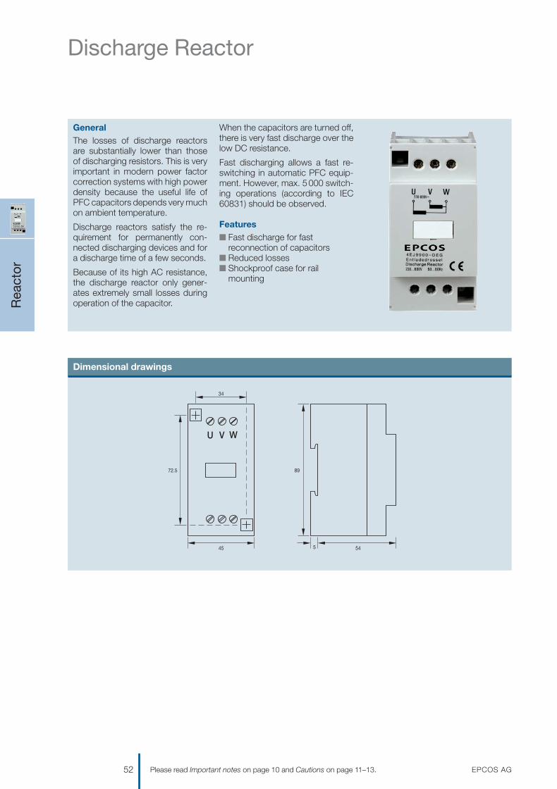
Discharge Reactor
Rea
ctor
52 EPCOS AGPlease read Important notes on page 10 and Cautions on page 11–13.
GeneralThe losses of discharge reactorsare substantially lower than those of discharging resistors. This is veryimportant in modern power factorcorrection systems with high powerdensity because the useful life ofPFC capacitors depends very muchon ambient temperature.
Discharge reactors satisfy the re-quirement for permanently con-nected discharging devices and fora discharge time of a few seconds.
Because of its high AC resistance,the discharge reactor only gener-ates extremely small losses duringoperation of the capacitor.
When the capacitors are turned off,there is very fast discharge over thelow DC resistance.
Fast discharging allows a fast re-switching in automatic PFC equip-ment. However, max. 5000 switch-ing operations (according to IEC60831) should be observed.
Featuresn Fast discharge for fast
reconnection of capacitorsn Reduced lossesn Shockproof case for rail
mounting
Dimensional drawings
U V W
72.5
45
34
89
545
1201070039_PFC_Katalog_07.qxd 14.08.2007 16:02 Uhr Seite 52

Discharge Reactor
Rea
ctor
EPCOS AG 53Please read Important notes on page 10 and Cautions on page 11–13.
Technical data
Ordering code B44066E9900S001
Voltage VR 230 ... 525 V
Frequency f 50 / 60 Hz
Internal configuration 2 windings in V arrangement
Resistance R 4 900 Ω
Discharge time t 230 V up to 25 kvar < 10 s / up to 50 kvar < 20 s /up to 100 kvar < 40 s
400 … 525 V up to 25 kvar < 5 s / up to 50 kvar < 10 s / up to 100 kvar < 20 s
Power loss PLOSS < 1.8 W
Free-wheeling current I < 4.5 mA
Accepted discharge 1 x / (minute and 100 kvar)number
Insulation class RINS T40/B
Cable diameter ø 0.75 … 2 x 2.5 mm2
Terminals fixing torque 0.5 Nm
Installation location indoor
Ambient temperature –25 … + 55 °C
Cooling natural
Dimensions 90 x 45 x 59 mm
Weight 0.5 kg
1201070039_PFC_Katalog_07.qxd 14.08.2007 16:02 Uhr Seite 53

Dynamic Power Factor CorrectionThyristor Module TSM-Series
TSM
-Ser
ies
54 EPCOS AGPlease read Important notes on page 10 and Cautions on page 11–13.
Featuresn Easy installation: it can be used
similar as a contactorn All the intelligence needed is
offered within the thyristor moduleitself
n Reaction time: 5 milliseconds onlyn Permanent self-controlling of:
– voltage parameter– phase sequence– capacitor output
n Display of– operation– faults– activation
General
Conventional systems for power fac-tor correction are used to optimizethe power factor and reduce the levelof harmonics in the grid. The usageof new technologies in modern in-dustry has negative impacts on elec-tric power quality of the main supplynetworks, e.g. frequent high loadfluctuations and harmonic oscilla-tion. Excessive currents, increasedlosses and flickering will not only in-fluence the supply capacity but willalso have a significant impact on the operation of sensitive electronicdevices. The solution for this aredynamic power factor correctionsystems.
With the thyristor module seriesTSM-LC and TSM-HV we provide the main component – “electronicswitch” – for dynamic power factorcorrection. The TSM module series are a fast electronically controlled, self-observing thyristor switch for capacitive loads up to 200 kvar,which is capable to switch PFC capacitors within a few millisecondsas often as required.
V Cautions:Live parts in the PFC equipmentmust not be touched!
Warning signs in the PFC systemsare required!
Wait 10 minutes after the mainswitch is turned off – until the voltagein the system has dropped to anuncritical value.
In non-detuned systems (400 V grid)capacitors with a higher voltagerating (e.g. 440 V) are needed.
In detuned systems (400 V grid) ca-pacitors with a voltage of 525 V areneeded.
For discharging the capacitors,special high-voltage resistors type EW-22 are required. Standard re-sistors cannot be used!
In dynamic PFC systems dischargereactors cannot be used (this would be a short circuit of the high-voltage DC)!
In PFC systems without filter circuitreactors current limiting reactors arerequired (e.g. BD-100) for the TSM.
For short circuit protection, superfastelectronic fuses for protection of thethyristor are required, standard HRCfuses are not suitable:
TSM-LC 10: 35 A/690 VTSM-LC 25: 63 A/690 VTSM-LC 50: 125 A/690 VTSM-LC 200: 450 A/690 VTSM-HV 50: 100 A/690 V3 pieces per module required.
V Failure to follow cautions mayresult, worst case, in prematurefailures or physical injury.
1201070039_PFC_Katalog_07.qxd 14.08.2007 16:02 Uhr Seite 54

Dynamic Power Factor CorrectionThyristor Module TSM-Series
TSM
-Ser
ies
EPCOS AG 55Please read Important notes on page 10 and Cautions on page 11–13.
Technical data
Voltage TSM-LC-series: 3 x 400 V, TSM-HV-series: 690 V
Max. power TSM-LC 10: 10 kvar for PFC systems with / without reactors up to 14%(up to max. 12.5 kvar at 400 V with ambient temperature < 40 °C)
TSM-LC 25/50/200: 25 kvar/50 kvar/200 kvar for PFC systems with / without reactors up to 14%TSM-HV 50: up to max. 60 kvar at 690 V
A cascading of several modules is possible for increasing the kvar output.
Activation 10 … 24 V DC, internal insulated
Switching time approx. 5 ms
Control features voltage (availability and value), phase sequence, capacitor output
Power circuit TSM-LC 10: Direct connection 4 pole via terminal clamps (D = 6 mm2 resp., 4 mm2)TSM-LC 25/50: Direct connection 4 pole via busbar (cable lug 25 mm2, D = 8 mm2)TSM-LC 200: Direct connection 4 pole via busbar (cable lug 185 mm2, D = 12 mm2)TSM-HV 50: Direct connection 4 pole via busbar (cable lug 25 mm2, D = 8 mm2)
Losses TSM-LC 10: PD (in W) = 2.0 · l (in A); at 400 V/12.5 approx. 35 WTSM-LC 25/50: PD (in W) = 2.0 · l (in A); typical 75 W/150 W (thermal)TSM-LC 200: PD (in W) = 2.0 · l (in A); at 400 V/200 kvar approx. 580 W (thermal)TSM-HV 50: PD (in W) = 3.0 · l (in A); at 690 V/50 kvar approx. 125 W (thermal)
Fuses TSM-LC 10: 3x electronic fuse “superfast” NH00 AC 690 V12.5 kvar: 35 A (e.g. SIBA Art. No. 20.477.20-35)
TSM-LC 25/50: Electronic fuse “superfast” NH00 AC 690 V25 kvar: 63 A (e.g. SIBA Art. No. 20.209.20-63)50 kvar: 125 A (e.g. SIBA Art. No. 20.209.20-125)
TSM-LC 200: 3x electronic fuse “superfast” NH2 AC 690 V125 kvar: 315 A (e.g. SIBA Art. No. 20.212.20.315)150 kvar: 350 A (e.g. SIBA Art. No. 20.212.20.350)200 kvar: 450 A (e.g. SIBA Art. No. 20.212.20.450)
TSM-HV 50: 3x electronic fuse “superfast” NH00 AC 690 V50/60 kvar: max. 100 A (e.g. SIBA Art. No. 20.209.20-100)25 kvar: max. 63 A (e.g. SIBA Art. No. 20.209.20-63)
Dimensions TSM-LC 10: 162 x 150 x 75 mm, TSM-LC 25/50: 157 x 200 x 180 mm(w x h x d) TSM-LC 200: 250 x 480 x 160 mm, TSM-HV 50: 157 x 200 x 195 mm
Thyristor modules for dynamic power factor correction
Type Description Voltage Output Ordering code Packing kvar unit
V at 50 Hz
TSM-LC 10 RT PFC module 400 10 B44066T0010E402 1
TSM-LC 25 RT PFC module 400 25 B44066T0025E402 1
TSM-LC 50 RT PFC module 400 50 B44066T0050E402 1
TSM-LC 200 RT PFC module 400 200 B44066T0200E402 1
TSM-HV 50 RT PFC module 690 50 B44066T0050E690 1
Accessories for TSM-LC modules 10/25/50
Type/Description Ordering code Packing unit
Discharge resistors EW-221)
to be used for 10, 25 kvar or 50 kvar stage, one unit per stage required2) B44066T0022E400 1
Current limitation reactor BD-100 for PFC systems without detuning reactorsto be used for 10, 25 kvar or 50 kvar step, two units per step required2) B44066T0100E400 1
1) Consisting of two single resistors of 22 kΩ each2) Not suitable for TSM-LC 200 and TSM-HV 50
EW-22
1201070039_PFC_Katalog_07.qxd 14.08.2007 16:02 Uhr Seite 55

Dynamic Power Factor CorrectionThyristor Module TSM-Series
TSM
-Ser
ies
56 EPCOS AGPlease read Important notes on page 10 and Cautions on page 11–13.
Dynamic PFC network: one stage
Input (controller signal)
L1 (R)
L2 (S)
L3 (T)
NPE
Capacitorbranch
Fuse superfast125 A at 50 kvar63 A at 25 kvar
1201070039_PFC_Katalog_07.qxd 14.08.2007 16:02 Uhr Seite 56

Dynamic Power Factor CorrectionThyristor Module TSM-Series
TSM
-Ser
ies
EPCOS AG 57Please read Important notes on page 10 and Cautions on page 11–13.
Dynamic PFC network: multiple stages
1st Capacitorbranch
L1 (R)
L2 (S)
L3 (T)N
PE
Input(controller signal)
L
2nd Capacitorbranch
3rd Capacitorbranch
Fuse superfast125 A at 50 kvar 63 A at 25 kvar
Fuse superfast Fuse superfast
Filter *
DischargeResistor Ew22
PowerCapacitor
N L N k l
U Um lmInterferencemessage
relay
a b P1 1 2 3 4 5 6
+ 24V –
T2A
T2A
power factorcontroller
BR6000-T12
supply-voltage
Vb
meas.voltage
Vmmeas. current
Im (5A/1A)
k l
1201070039_PFC_Katalog_07.qxd 14.08.2007 16:02 Uhr Seite 57

Fundamentals of Power Factor Correction
The rational use of electrical energycalls for economical generation,transmission and distribution withlittle loss. That means restricting allfactors in electrical networks thatcause losses. One of these factors islagging reactive power. Loads inindustrial and public electrical net-works are primarily of an ohmic-inductive nature.
The purpose of systems for powerfactor correction in networks is tocompensate the generated laggingreactive power by leading reactivepower at defined nodes. In this wayimpermissibly high voltage dropsand additional ohmic losses are alsoavoided. The necessary leadingpower is produced by capacitorsparallel to the supply network, asclose as possible to the inductiveload. Static capacitive compensationdevices reduce the lagging reactivepower component transmitted overthe network. If network conditionsalter, the required leading reactivepower can be matched in steps byadding and taking out single powercapacitors (automatic PFC) to com-pensate the lagging reactive power.
Benefits of power factor correction
n Payback in 8 to 24 months throughlower power costs
Power factor correction reduces thereactive power in a system. Powerconsumption and thus power costsdrop in proportion.
n Effective installation useAn improved power factor meansthat an electrical installation worksmore economically (higher effectivepower for the same apparent power).
n Improved voltage quality
n Reduced voltage drop
n Optimum cable design
Cable cross-section can be reducedwith improvement of power factor(less current). In existing installationsfor instance, extra or higher powercan be transmitted.
n Reduced transmission lossesThe transmission and switching de-vices carry less current, i.e. only theeffective power, meaning that theohmic losses in the leads are re-duced.
Key components
Capacitor
Power factor correction capacitorsproduce the necessary leading re-active power to compensate the lag-ging reactive power. PFC capacitorsshould be capable of withstandinghigh inrush currents caused byswitching operations (> 100 · IR). Ifcapacitors are connected in parallel,i.e. as banks, the inrush current willincrease (≥ 150 · IR) because thecharging current comes from the gridas well as from capacitors parallel tothe one switched.
PFC controller
Modern PFC controllers are micro-processor-based. The microproces-sor analyzes the signal from a currenttransformer and produces switchingcommands to control the contactorsthat add or remove capacitor stages.Intelligent control by microproces-sor-based PFC controllers ensureseven utilization of capacitor stages,minimized number of switchingoperations and optimized life cycle ofthe capacitor bank.
Capacitor contactor
Contactors are electromechanicalswitching elements used to switchcapacitors or reactors and capaci-tors in standard or detuned PFCsystems. The switching operationcan be performed by mechanicalcontacts or an electronic switch(semiconductor). The latter solutionis preferable if fast switching is required for a sensitive load forexample.
Reactor (compensation and filtering)
Power distribution networks are in-creasingly subjected to harmonicpollution from modern power elec-tronic devices, so called nonlinearloads, e.g. drives, uninterruptiblepower supplies, electronic ballasts.Harmonics are dangerous forcapacitors connected in the PFCcircuit, especially if the capacitorsoperate at resonant frequency. Theseries connection of reactor andcapacitor to detune the series res-onant frequency (the capacitor’sresonant frequency) helps to preventcapacitor damage. Most criticalfrequencies are the 5th and 7th har-monics (250 and 350 Hz at 50 Hz).Detuned capacitor banks also helpto reduce the harmonic distortionlevel and clean the network.
Fuse
A HRC fuse or MCCB acts as a safe-ty device for short circuit protection.n HRC fuses do not protect a ca-
pacitor against overload – they arefor short circuit protection only.
n The HRC fuse rating should be 1.6 to 1.8 times nominal capacitorcurrent.
V Do not use HRC fuses forswitching (risk of arcing!). Referto page 12.
Fund
amen
tals
of P
FC
58 EPCOS AGPlease read Important notes on page 10 and Cautions on page 11–13.
1201070039_PFC_Katalog_07.qxd 14.08.2007 16:02 Uhr Seite 58

Fundamentals of Power Factor Correction
Fund
amen
tals
of P
FC
EPCOS AG 59Please read Important notes on page 10 and Cautions on page 11–13.
Application examples
Conventional power factor correction Harmonic filter with dynamic PFC
kWh meter
Apparentpower
Capacitors forcompensation
kvarh meter
GridP
SQ
50%
50%
100%
PFCCNTRL.
Harmonicscompensation
X
M3�
M3�
PFC controller
PFCcapacitors
Fuses
Thyristormodules
Capacitor contactors
Reactors
Power factor correction system with filter circuit reactors for reduction of harmonics.
1201070039_PFC_Katalog_07.qxd 14.08.2007 16:03 Uhr Seite 59

Fundamentals of Power Factor Correction
Power factor correction
To achieve optimum power factorcorrection, a PFC system has to bedesigned for the reactive power re-quired. The best method is to per-form active and reactive powermeasurements prior to design. Mea-surements have to cover all impor-tant time periods during day- andnighttime to obtain reliable values forpeak reactive power requirements.
PFC formulas (active, reactive,apparent power)
Active power
The amount of input power con-verted into output power is termedactive power and generally indicatedby P in watts [W] and defined by thefollowing formula:
P = ��3 · V · I · cos ϕ [W]
The entire input power, e.g. apparentpower, should be converted intouseful output power stated as activepower, e.g. the real motor poweroutput. The quality of such a powerconversion is indicated as cos ϕ, theunity power factor.
Reactive power
Electrical machines work on the prin-ciple of conversion of electromag-netic energy (e.g. electric motors,transformers). Part of the input ener-gy is consumed to create and main-tain the magnetic field. Inductiveloads shift the angle between voltageand current (to a value > 0). Powercreated by portions of V and Iwaveforms having opposite direc-tions (+ and –) is called reactivepower. This part of the energy(magnetic reversal energy), definedas reactive power Q in volt amperereactive [var], cannot be convertedinto active power and is returned tothe electrical supply network duringchanges of the magnetic field. Butthe same amount of energy will beconsumed by the network again andrequired for the next change of themagnetic field.
Q = ��3 · V · I · sin ϕ [var]
Apparent Power
In principle, applications of electricalequipment are based on conversionof electrical energy into some otherform of energy. The electrical powerdrawn by equipment from the sourceis termed apparent power, indicatedby S in volt ampere [VA], and consistsof active and reactive power.
S = ��3 · V · I [VA]
Power factor
Electrically, the power factor (indi-cated by k) of an electric circuit isdefined as the cosine of the phaseangle between the fundamental ofvoltage and current waveforms.Another definition of power factor isthe ratio between active power andapparent power.
power factor cos ϕ = active power / apparent power = P / S
Reactive power compensation
Magnetic reversal energy supplied tothe network (reactive power) in cir-cuits without compensation can bestored temporarily in capacitors andthen used for the next change ofmagnetism, i.e. circuits with reactivepower compensation. To calculatethe required capacitor reactive pow-er QC in volt ampere reactive [var],the following formula is used:
QC = P · (tan ϕ1 – tan ϕ2) [var]
A capacitor of QC kvar will compen-sate the inductive Q and compen-sate to a cos ϕ of 1. It is not commonpractice to aim for a cos ϕ of 1 byinstallation of capacitors since it may result in overcompensation dueto load changes and response time of the controller. Generally,public utilities or power companiesspecify a value (cos ϕ2) to which the existing power factor (cos ϕ1)should be corrected.
Fund
amen
tals
of P
FC
60 EPCOS AGPlease read Important notes on page 10 and Cautions on page 11–13.
1201070039_PFC_Katalog_07.qxd 14.08.2007 16:03 Uhr Seite 60

Fundamentals of Power Factor Correction
Connection and rating of capacitors
A general expression for the kvarrating of a capacitor:
Capacitor in single-phase PFCapplication
The capacitor is connected betweenthe phase and neutral conductorsand is subjected to the phase-neutralvoltage (see above).
Capacitor in three-phase PFCapplication
n STAR connectionThe capacitor is subject to a voltageof (VL / ��3).
Thus total kvar compensation iscalculated as:
DELTA connection
The capacitor is subjected to linevoltage VL, phase to phase.
Thus total kvar compensation iscalculated as:
QTOT = 3 · (VL)2 · � · C
QTOT QTOTCDELTA = –––––––––– = ––––––––––––––3 · (VL)2 · � 3 · (VL)2 · 2� · f
(VL)2QTOT = 3 · –––––– · � · C(��3)2
QTOT QTOTCSTAR = ––––––––– = –––––––––––––(VL)2 · � (VL)2 · 2� · f
QC = VC · IC [var]
VC · VC (VC)2QC = –––––––– = –––––XC XC
1 1XC = ––––– = –––––––––� · C 2� · f · C
QC = (VC)2 · � · C = (VC)2 · 2� · f · C
As a conclusion one can say:
CSTARCDELTA = ––––––3
So PFC configurations are usuallydelta connected because star con-nection requires three times the ca-pacitance of a delta connection.
Calculation of capacitor rating forindustrial installation
n Example 1: Given parameters:
Calculation: Capacitor ratings for – STAR connection– DELTA connection
Target to correct the power factor to 0.9:
118.8 kvar
440 V/ 50 Hz
M
220 kWcos ϕ = 0.7
cos ϕ1 = 0.7 tan ϕ1 = 1.02cos ϕ2 = 0.9 tan ϕ2 = 0.48
QC = P (tan ϕ1 – tan ϕ2) = 220 · 1000 (1.02 – 0.48) = 118.8 kvar
Induction motor 220 kWNetwork 440 VAC, (line delta) 3-phaseFrequency 50 HzPower factor– Current cos ϕ 0.7– Target cos ϕ 0.9
n STAR connection:
n DELTA connection:
Delta connection
VL651 μF
VC = VL = 440 V
QTOT QTOTCDELTA = –––––––––– = ––––––––––––––3 · (VL)2 · � 3 · (VL)2 · 2� · f
118.8 · 1000CDELTA = –––––––––––––––––––––3 · (440)2 · 2� · 50
= 651 μF / Line (phase)
CTOT = 1954 μF
Star connection
VL
1954 μF
VL 440VC = –––– = –––– = 254 V��3 ��3
QTOT QTOTCSTAR = ––––––––– = –––––––––––––(VL)2 · � (VL)2 · 2� · f
118.8 · 1000CSTAR = –––––––––––––––––(440)2 · 2� · 50
= 1954 μF / Line (phase)
CTOT = 5862 μF
Fund
amen
tals
of P
FC
EPCOS AG 61Please read Important notes on page 10 and Cautions on page 11–13.
1201070039_PFC_Katalog_07.qxd 14.08.2007 16:03 Uhr Seite 61

Fundamentals of Power Factor Correction
Capacitor type selection (e.g. PhaseCap B25667…)
To reach the target cos ϕ of 0.9,118.8 kvar are required.
Apparent power transmission
Due to power factor correction,the required apparent power trans-mission can be reduced by the valueS1 – S2.
S1 uncompensated load:
S2 compensated load:
Reduction of apparent power aftercompensation:
S1 – S2 = 70 kVA
Thus, additional power of 70 · (0.9) = 63 kW can be supplied and transferred viathe existing network.
S2 = P / cos ϕ2 = 220 / 0.9= 244 kVA
S1 = P / cos ϕ1 = 220 / 0.7= 314 kVA
25 kvar · 4 +18.8 kvar = 118.8 kvar= 4 pcs B25667A4417A375 +
1 pc B25667A4307A365 = 4 · 3 · 137 + 1 · 3 · 103 = 1953 μF / phase
The power losses decrease with thesquare of the current.
The resistive transmission losses(power loss) PV are reduced by:
Cable cross-section calculation
Line current drawn by the motor:
I1 uncompensated load (0.7):
220 · 1000I1 = ––––––––––––––––– = 412 A��3 · 440 · (0.7)
I2 compensated load (0.9):
220 · 1000I2 = ––––––––––––––––– = 320 A��3 · 440 · (0.9)
Thus, the cable can carry anadditional load of 92 A, or thedesigner can reduce the cable cross-section.
(S12 – S22) · 100% =S12
[(314)2 – (244)2] · 100% = 39.6%(314)2
PV1 – PV2 = I12 – I22
= approx. S12 – S22
n Example 2: Given parameters:
Calculation of compensation:
to be compensated to meet thepower factor requirement set by thepower utility. Common compensa-tion would recommend a capacitorof at least 50 kvar.
Calculation using capacitor’s re-active power QC table:
The required appropriate compen-sation to meet a cos ϕ of 0.93 is≥ 52.0 kvar.
Capacitor output in case ofoperating voltage and/or frequencydifferent to nominal ratings
VNew 2 fNewQNew = (––––– ) · –––– · QCVR fR
cos ϕa (actual) = 0.75*cos ϕt (target) = 0.94** the cross point indicates factor
F = 0.52
QC = P · F = 100 · 0.52 = 52.0 kvar
QC = P · (tan ϕ1 – tan ϕ2)= 100 · (0.88 – 0.4)= 48 kvar
– Active powerP = 100 kW (peak)
– Actual cos ϕ=0.75= ϕ = 41.5° = tan ϕ1 = 0.88
– Target cos ϕ*= 0.93 = ϕ = 21.5° = tan ϕ2 = 0.4
* set by power utility
Fund
amen
tals
of P
FC
62 EPCOS AGPlease read Important notes on page 10 and Cautions on page 11–13.
1201070039_PFC_Katalog_07.qxd 14.08.2007 16:03 Uhr Seite 62

Fundamentals of Power Factor CorrectionInstallation and maintenance
Ambient temperature
Capacitors are divided into tempera-ture classes. Each class is repre-sented by a number followed by aletter, e.g. –25 °/D. The number is the lowest ambient temperature atwhich a capacitor may operate. Theupper limit temperature is indicatedby the letter D, standing for 55 °C. A maximum case temperature of60 °C must not be exceeded.Temperature is one of the mainstress factors for polypropylenecapacitors, having a major effect ontheir useful life. For higher tempera-ture requirements up to 70 °C (withnatural cooling) MKV capacitors fromEPCOS should be selected.
V Exceeding maximum allowedtemperature may set the safetydevice out of operation.
Inrush current
Switching LV PFC capacitors, espe-cially when they are in parallel withothers that are already energized,can cause high inrush currents of upto 200 times rated current. This leadsto additional stress on contactors aswell as capacitors and reduces theiruseful life. In addition, high inrushcurrents have a negative effect onpower quality, producing transientsand voltage drops for example.
Although the MKK AC design with itswavy cut features excellent pulse with-stand capability, limitation of inrushcurrent is still recommended, e.g. ca-pacitor contactors with inrush currentlimiting resistors or series – inductance(i.e. detuned harmonic filter).
As per IEC 60831 standard, a maxi-mum of 5 000 switching operationsis acceptable. Before considering ahigher number of switching opera-tions, please contact EPCOS.
Harmonics
Harmonics are produced in the oper-ation of electric loads with a non-linear voltage /current characteristic(e.g. rectifiers and inverters fordrives, welding apparatus and un-interruptible power supplies). Har-monics are sinusoidal voltages andcurrents with higher frequencies of a
multiple of the 50 or 60 Hz line fre-quency.
Note: In applications subject to har-monics, you should only use powercapacitors with reactors, so calleddetuned capacitor banks. Depend-ing on the selected series resonantfrequency, part of the harmoniccurrent is absorbed by the powercapacitor. The remainder of theharmonic current flows into thesuperordinate system. The use ofpower capacitors with reactors re-duces harmonic distortion andlessens the disturbing effect on prop-er operation of other electric loads.
A major reason for installing detunedcapacitor banks is to avoid reso-nance. Resonance can multiply ex-isting harmonics and create powerquality problems, as well as causingdamage to distribution equipment.
Resonance cases must beavoided by appropriate appli-cation design in any case!
Max. total RMS capacitor current(incl. fundamental harmonic cur-rent) specified in technical dataof the specific series must not beexceeded.
V Safety
n Ensure good effective groundingfor capacitor enclosures.
n Provide means of disconnectingand insulating a faulty compo-nent /bank.
n Handle capacitors carefully, be-cause they may still be chargedeven after disconnection due tofaulty discharging devices.
n Follow good engineering practice.n Do not use HRC fuses to power a
capacitor up and down (risk ofarcing).
n Remember that the terminals ofcapacitors, connected bus barsand cables as well as other de-vices may also be energized.
Overcurrent and short circuitprotection
n Use HRC fuses or MCCBs forshort circuit protection. Shortcircuit protection and connectingcables should be selected so that
1.5 times the rated capacitor cur-rent can be permanently handled.
n HRC fuses do not protect a ca-pacitor against overload – they areonly for short circuit protection.
n The HRC fuse rating should be 1.6 to 1.8 times rated capacitorcurrent.
n Do not use HRC fuses to switchcapacitors (risk of arcing).
n Use thermal / thermal magneticovercurrent relays for overloadprotection.
Maintenance
n Periodically check that connec-tions and terminals are tight.
n Regularly clean terminals /bush-ings to avoid short circuits due todust and soiling.
n Check short circuit protectionfuses.
n Make a current reading twice an-nually to see if application condi-tions have altered.
n Consider upgrading or modifyingthe PFC system if the applicationenvironment has changed.
n In the event of a current abovenominal, check your applicationfor possible modification.
n In the event of a significant in-crease in nonlinear loading, call ina consultant for a harmonics ex-amination.
n If harmonics are present, considerinstallation of a detuned capacitorbank (reactors).
n Check discharge resistors / reac-tors and their functioning:– Power the capacitor up and
down.– The voltage across the terminals
must fall to < 75 V within 60 s.
Capacitor life expectancy
Capacitors operation between anyrated value and the correspondingabsolute maximum rating is an over-load that derates life expectancy ofthe device.
Simultaneous overload conditions orexceeding any absolute maximumrating may reduce life expectancysignificantly.
Fund
amen
tals
of P
FC
EPCOS AG 63Please read Important notes on page 10 and Cautions on page 11–13.
1201070039_PFC_Katalog_07.qxd 14.08.2007 16:03 Uhr Seite 63

Fundamentals of Power Factor CorrectionInstallation and maintenance
Fund
amen
tals
of P
FC
64 EPCOS AGPlease read Important notes on page 10 and Cautions on page 11–13.
Mounting
≥ 20 mm
≥ 20 mm
Power capacitors should be installed in a cool and well ventilated location, and not close to objects that give off heat,like filter circuit reactors and furnaces, or in direct sunlight.
Leave enough space on top ofthe capacitor and do not fix anymounting components at thecrimp or on top to allow longitu-dinal expansion of the can andproper functioning of the over-pressure disconnector.
The M12 stud also serves for grounding. Connect toground or connect the capacitor to other conductiveitems that are grounded. Note that suitable connectorsmust penetrate existing layers of lacquer to achievegood and constant conduction and sufficient current-carrying capability.
Tighten the threaded M12 stud on the bottom of thecase with 10 Nm torque.
A minimum spacing of 20 mm isnecessary between capacitors toensure proper cooling.
Mounting
PhaseCap, WindCap:Any mounting position of the capacitoris possible, vertical and horizontal.
Remember to ensure sufficient cooling.
Capacitors installed in a cabinet shouldbe at the bottom to ensure the leasttemperature stress.
1201070039_PFC_Katalog_07.qxd 14.08.2007 16:03 Uhr Seite 64

Fundamentals of Power Factor CorrectionInstallation and maintenance
Fund
amen
tals
of P
FC
EPCOS AG 65Please read Important notes on page 10 and Cautions on page 11–13.
Connection of supply cables for PhaseCap Premium, PhaseCap HD, WindCap, PhiCap
KLK1683-Y
Contact BlockScrew Terminal
ContactBody Block
Contact Bar
CeramicFeed Through
OhmicDischargeResistor
Connection CableCross Section,16/35 m 2 max.
Connection of capacitors in parallel not recommended; max. 50 A (16 mm2) resp. 130 A (35 mm2) must not be exceeded at any case!
When connecting supply cables, observe the maximumpermissible torque of 1.2 Nm for PhaseCap Premium,WindCap and PhiCap; 2.5 Nm for PhaseCap HD.
The connecting cable should be flexible and of copper.
Do not use hard core cable!
Maximum cable cross-section is 16 mm2 for PhaseCap Premium, WindCap and PhiCap; 35 mm2 for PhaseCap HD.
Discharge resistorsn Discharge resistors are required to
discharge capacitors and protecthumans against electric shockhazard as well as to switch capac-itors in automatic PFC equipment(opposing phase).
n EPCOS discharge resistorsarede-signed to discharge capacitors to75 V or less within 60 seconds(types marked with 4) in the table ofordering codes: ≤ 75 V in 90 sec-onds).
n Before switching again, capacitorsmust be discharged to 10% or lessof nominal voltage.
n Discharge resistors are included indelivery.
V Caution: Discharge and shortcircuit capacitor before handling!
1201070039_PFC_Katalog_07.qxd 14.08.2007 16:03 Uhr Seite 65
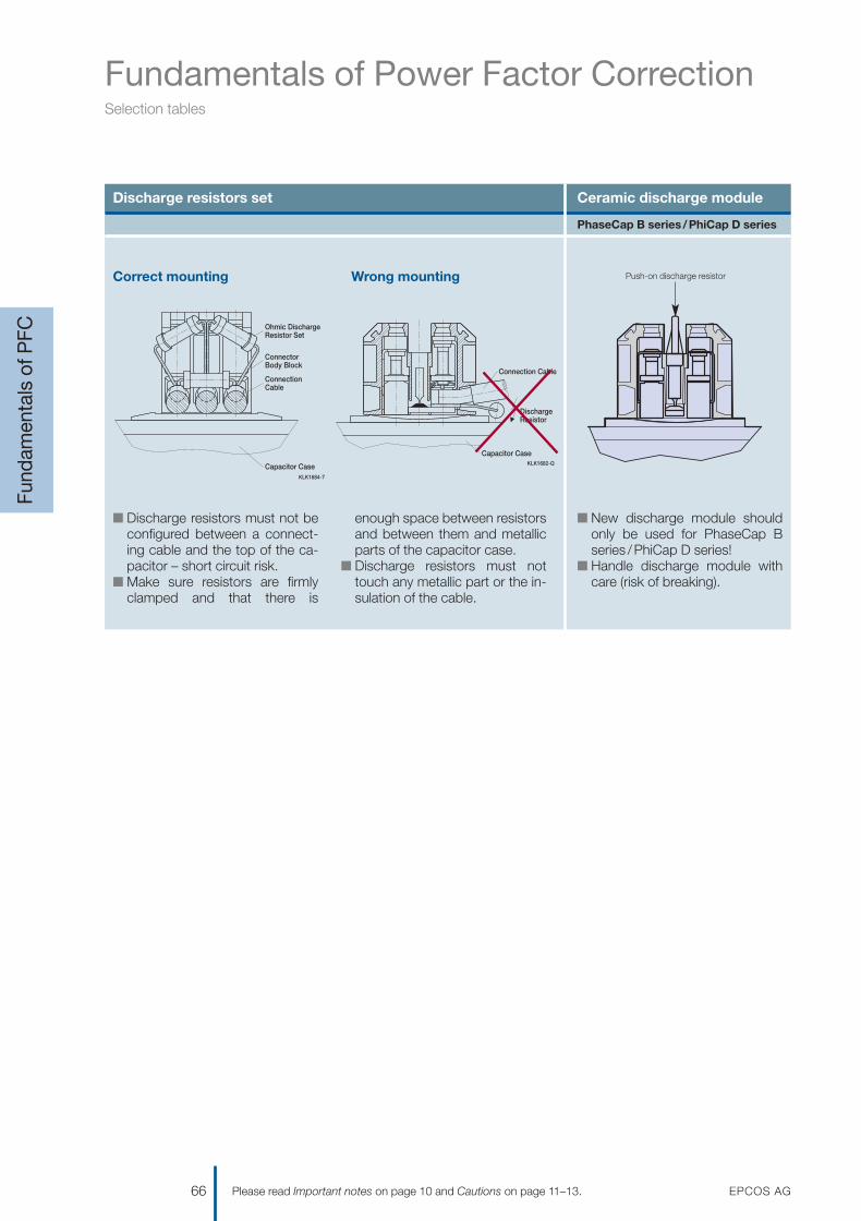
Fundamentals of Power Factor CorrectionSelection tables
Fund
amen
tals
of P
FC
66 EPCOS AGPlease read Important notes on page 10 and Cautions on page 11–13.
Discharge resistors set Ceramic discharge module
n Discharge resistors must not beconfigured between a connect-ing cable and the top of the ca-pacitor – short circuit risk.
n Make sure resistors are firmlyclamped and that there is
enough space between resistorsand between them and metallicparts of the capacitor case.
n Discharge resistors must nottouch any metallic part or the in-sulation of the cable.
n New discharge module shouldonly be used for PhaseCap B series /PhiCap D series!
n Handle discharge module withcare (risk of breaking).
KLK1684-7
Resistor Set
ConnectionCable
ConnectorBody Block
Capacitor Case
Ohmic Discharge
KLK1682-Q
Capacitor Case
Connection Cable
DischargeResistor
Correct mounting Wrong mounting Push-on discharge resistor
PhaseCap B series /PhiCap D series
1201070039_PFC_Katalog_07.qxd 14.08.2007 16:03 Uhr Seite 66

Selection of connecting cablecross-section, HRC fuse rating
The cross-section figures are guide-lines for operation in normal con-ditions at ambient temperatures upto 40 °C. Upgrade accordingly ifconditions, e.g. temperature or har-monics, differ.
The internal wiring of a capacitorbank is normally possible with asmaller cross-section. Various para-meters such as temperature insidethe cabinet, cable quality, maximumcable isolation temperature, single-or multi-core cable and cable lengthhave to be considered for properselection.
Fundamentals of Power Factor CorrectionSelection tables
Fund
amen
tals
of P
FC
EPCOS AG 67Please read Important notes on page 10 and Cautions on page 11–13.
Standard values: selection table for cables and cross-sections
Power 230 V– 60 Hz 400 V– 50 Hz 440 V– 60 Hz 480 V– 60 HzCurrent Fuse Sect. Current Fuse Sect. Current Fuse Sect. Current Fuse Sect.
kvar A A mm2 A A mm2 A A mm2 A A mm2
2.5 6.3 10 2.5 3.6 10 1.5 3.3 10 1.5 3 10 1.5
5 12.6 25 4 7.2 16 2.5 6.6 16 2.5 6 16 2.5
7.5 18.8 35 6 10.8 16 2.5 9.9 16 2.5 9 16 2.5
10 25.1 50 10 14.4 25 4 13.2 25 4 12 25 4
15 37.7 63 16 21.6 35 6 19.8 35 6 18 35 6
20 50.2 80 25 28.8 50 10 26.4 50 10 24 50 10
25 62.8 100 35 36.0 63 16 33.0 63 16 30 50 16
30 75.3 125 50 43.2 80 25 39.6 80 25 36 63 25
40 100.4 160 70 57.6 100 35 52.8 100 35 48 80 35
50 125.5 200 120 72.0 125 35 66.0 125 35 60 100 35
75 188.3 350 2 x 95 108.0 160 70 99.0 160 70 90 160 70
100 251.0 400 2 x 120 144.0 250 120 132.0 200 120 120 200 120
150 – – – 216.0 350 2 x 95 198.0 350 2 x 95 180 350 2 x 95
200 – – – 288.0 500 2 x 120 264.0 500 2 x 120 240 400 2 x 120
1201070039_PFC_Katalog_07.qxd 14.08.2007 16:03 Uhr Seite 67

Fundamentals of Power Factor CorrectionSelection tables
Fund
amen
tals
of P
FC
68 EPCOS AGPlease read Important notes on page 10 and Cautions on page 11–13.
Standard values: selection table for fixed PFC
Individual motors Transformers
Motor Capacitor power in kvar (according to RPM) Transfomer Capacitor powerHP 3000 1500 1000 750 500 kVA kvar
2.5 1 1 1.5 2 2.5 100 5
5 2 2 2.5 3.5 4 160 6.25
7.5 2.5 3 3.5 4.5 5.5 200 7.5
10 3 4 4.5 5.5 6.5 250 10
15 4 5 6 7.5 9 315 12.5
20 5 6 7 9 12 400 15
25 6 7 9 10.5 14.5 500 20
30 7 8 10 12 17 630 25
40 9 10 13 15 21 800 30
50 11 12.5 16 18 25 1000 40
60 13 14.5 18 20 28 1250 50
70 15 16.5 20 22 31 1600 60
80 17 19 22 24 34 2000 80
90 19 21 24 26 37
100 21 23 26 28 40
120 25 27 30 32 46
150 31 33 36 38 55
180 37 39 42 44 62
200 40 42 45 47 67
225 44 46 49 51 72
250 48 50 53 65 76
Individual PFC for motors
The capacitor output should beapprox. 90% of the apparent powerof the motor when idle. This means a power factor of 0.9% at full loadand 0.95–0.98 during idling.
Important: The capacitor outputmust not be rated too high forindividual compensated machineswhere the capacitor is directlyconnected with the motor clamp.This especially applies when themachine has a big oscillating weightand still continues to rotate afterswitching off. The capacitor placed in parallel may act as a generator for the motor which will cause seri-ous overvoltages. The consequencecould be heavy damage to thecapacitor as well as to the motor.
Individual PFC of transformers
There are regional differences in theguidelines of power suppliers con-cerning the admissible size of ca-pacitors directly connected with atransformer. Therefore a consultationwith the respective power supplier is recommended before installationof a compensation bank. Moderntransformers have laminations whichonly need low capacity to reverse themagnetism. In case the capacitoroutput is too high, stress increasemay occur during idling.
Capacitors with built-in fuse switchesare suitable. When these capacitorsare directly connected to the trans-former clamps, you must make surethat the input lead to the capacitor israted for the full short circuit power.
V Important: The fuse switchesare operated by capacitive load.To avoid dangerous arcs, theymay never be drawn under load.
If disconnection of the capacitorshould be possible even when thetransformer is under operation, apower capacitor with automaticswitch must be chosen.
1201070039_PFC_Katalog_07.qxd 14.08.2007 16:03 Uhr Seite 68

Fundamentals of Power Factor CorrectionDetuned filtering (PFC-DF)
General
When installing capacitors for PFCpurposes, we face the problem ofdealing with harmonics. We have to take them into account when de-signing the PFC system in order toprevent parallel and / or series reso-nance conditions that would dam-age the whole electrical system.
When PFC capacitors are connect-ed, the inductance of the transformertogether with the capacitors form a resonant circuit that could beexcited by a harmonic current gener-ated by the load. This resonantcircuit has a resonance frequency,and if a harmonic current of thisfrequency (or close to it) exists, it willlead the circuit into a resonancecondition where high current will flowthrough the branches (L: the trans-former, and C: the capacitor bank),overloading them and raising thevoltage across them and across thewhole electrical system that is con-nected in parallel.
PFC detuned filtering is a techniqueto correct the power factor avoidingthe risk of resonance condition per-
formed by shifting the resonancefrequency to lower values where noharmonic currents are present.
This is achieved by modifying thebasic LC circuit formed by thetransformer and the capacitorbank, introducing a filter reactor inseries with the capacitors, makingthis way a more complex resonantcircuit but with the desired feature ofhaving a resonance frequency belowthe first existing harmonic. This wayit’s not possible to have a real reso-nance condition.
Besides this main objective, thereactor connected in series withcapacitors form a series resonantcircuit with a certain tuning frequencyat which the branch will offer a lowimpedance path. Filtering of harmon-ic currents and “cleaning” of the gridwill be achieved.
Components for PFC detuned filtersmust be carefully selected accordingto the desired PFC purpose, to theharmonics present in the system, tosome features of the system likeshort circuit power and impedances,to the desired filtering effect and to
the characteristics of the resonantcircuit configured.
For example, the voltage across thecapacitors will be higher than thenominal grid voltage when they havea reactor connected in series.
The reactors must be selected in linewith the inductance value to obtainthe desired tuning frequency andcurrent capability high enough for theharmonic current absorption thatcan be expected. The tuning fre-quency is usually indirectly referredto as the detuning factor p andexpressed as a percentage.
PFC detuned filtering is an engineer-ing speciality that takes experiencedknow-how to implement it in a satis-fying and safe way.
The next page shows some guide-lines for design and selection of com-ponents for PFC-DF.
Fund
amen
tals
of P
FC
EPCOS AG 69Please read Important notes on page 10 and Cautions on page 11–13.
1201070039_PFC_Katalog_07.qxd 14.08.2007 16:03 Uhr Seite 69

Fundamentals of Power Factor CorrectionDetuned filtering (PFC-DF)
Top 10 considerations for High-Performance PFC-DF
Determine the necessary effectivepower (kvar) of the capacitorbank in order to obtain the de-sired PF.
Design the capacitor stages insuch a way that the sensibility ofthe bank is around 15–20% of thetotal available power. It’s not use-ful to have a more sensitive bankthat reacts with a 5 or 10% of thetotal power because this wouldlead to a high amount of switch-ing operations, wasting theequipment unnecessarily whenthe real objective is to have a highaverage PF.
Try to design the bank withstandard kvar values of effectivepower steps, preferably multiplesof 25 kvar.
3
2
1
Measure the presence ofharmonic currents in the mainfeeder cable of the system with-out capacitors at all possible load conditions. Determinefrequency and maximum ampli-tude for every harmonic thatcould exist. Calculate the Total HarmonicDistortion of Current THD-I = 100· SQR [(I3)2 + (I5)2 + ... + (IR)2]/IlCalculate every existing value forTHD-IR = 100 · IR/Il
Measure the presence of har-monic voltages that might come from outside your system, if possible measure the HV side. Calculate the Total HarmonicDistortion of Voltage THD-V =100 · SQR [(U3)2 + (U5)2 + ... +(UN)2]/Ul
Are there harmonics such as THD-I > 10% or THD-V > 3%(measured without capacitors)?If YES � use PFC-DF and go toconsideration 7.If NO � use standard PFC andskip considerations 7, 8 and 9.
Is there 3rd harmonic content, I3 > 0.2 · I5? If YES � use PFC-DF with p =14% and skip consideration 8.If NO � use PFC-DF with p = 7% or 5.67% and go toconsideration 8.
7
6
5
4 THD-V is: 3–7% � use PFC-DF with p = 7% > 7% � use PFC-DF with p = 5.67% > 10% � ask for special filterdesign
Select the proper componentsusing EPCOS tables for PFC-DFand standard values for effectivepower, the voltage and frequencyof your grid, and the determineddetuned factor p.
Always use genuine EPCOSapplication-specific designedcomponents for PFC-DF. Pleaseobserve that reactors are speci-fied for their effective power atgrid voltage and frequency. Thispower will be the real effectivepower of the whole LC set atfundamental frequency. Capaci-tors for PFC-DF must be select-ed for a higher rated voltage thanthe grid’s because of the overvolt-age caused by the seriesconnection with the reactor.Contactors for capacitors aredesigned as application-specificto reduce inrush capacitorscurrents and to handle capacitiveloads in a reliable way.
10
9
8
Fund
amen
tals
of P
FC
70 EPCOS AGPlease read Important notes on page 10 and Cautions on page 11–13.
1201070039_PFC_Katalog_07.qxd 14.08.2007 16:03 Uhr Seite 70

Fundamentals of Power Factor CorrectionDefinition of capacitor reactive power Qc
Fund
amen
tals
of P
FC
EPCOS AG 71Please read Important notes on page 10 and Cautions on page 11–13.
QC = PA · (tan ϕ1– tan ϕ2)QC [kvar] = PA · F = active power [kW] · factor “F”
PA = S · cos ϕ = apparent power · cos ϕtan ϕ1 + ϕ2 according to cos ϕ values ref. table
Example:Actual motor power P = 100 kWACTUAL cos ϕ 0.61TARGET cos ϕ 0.96Factor F from table 1.01Capacitor reactive power QCQC = 100 · 1.01 = 101.0 kvar
TARGETcos ϕ = 0.96
Q
cos ϕ ≤ 1Qc = Pmot · F (0.96) = … [kvar]
100 · 1.01 = 101.0 kvar
Current Achievable (ACTUAL) (TARGET)tan ϕ cos ϕ cos ϕ
0.80 0.82 0.85 0.88 0.90 0.92 0.94 0.96 0.98 1.00
Faktor F
3.18 0.30 2.43 2.48 2.56 2.64 2.70 2.75 2.82 2.89 2.98 3.182.96 0.32 2.21 2.26 2.34 2.42 2.48 2.53 2.60 2.67 2.76 2.962.77 0.34 2.02 2.07 2.15 2.23 2.28 2.34 2.41 2.48 2.56 2.772.59 0.36 1.84 1.89 1.97 2.05 2.10 2.17 2.23 2.30 2.39 2.592.43 0.38 1.68 1.73 1.81 1.89 1.95 2.01 2.07 2.14 2.23 2.432.29 0.40 1.54 1.59 1.67 1.75 1.81 1.87 1.93 2.00 2.09 2.292.16 0.42 1.41 1.46 1.54 1.62 1.68 1.73 1.80 1.87 1.96 2.162.04 0.44 1.29 1.34 1.42 1.50 1.56 1.61 1.68 1.75 1.84 2.041.93 0.46 1.18 1.23 1.31 1.39 1.45 1.50 1.57 1.64 1.73 1.931.83 0.48 1.08 1.13 1.21 1.29 1.34 1.40 1.47 1.54 1.62 1.831.73 0.50 0.98 1.03 1.11 1.19 1.25 1.31 1.37 1.45 1.63 1.731.64 0.52 0.89 0.94 1.02 1.10 1.16 1.22 1.28 1.35 1.44 1.641.56 0.54 0.81 0.86 0.94 1.02 1.07 1.13 1.20 1.27 1.36 1.561.48 0.56 0.73 0.78 0.86 0.94 1.00 1.05 1.12 1.19 1.28 1.481.40 0.58 0.65 0.70 0.78 0.86 0.92 0.98 1.04 1.11 1.20 1.401.33 0.60 0.58 0.63 0.71 0.79 0.85 0.91 0.97 1.04 1.13 1.331.30 0.61 0.55 0.60 0.68 0.76 0.81 0.87 0.94 1.01 1.10 1.301.27 0.62 0.52 0.57 0.65 0.73 0.78 0.84 0.91 0.99 1.06 1.271.23 0.63 0.48 0.53 0.61 0.69 0.75 0.81 0.87 0.94 1.03 1.231.20 0.64 0.45 0.50 0.58 0.66 0.72 0.77 0.84 0.91 1.00 1.201.17 0.65 0.42 0.47 0.55 0.63 0.68 0.74 0.81 0.88 0.97 1.171.14 0.66 0.39 0.44 0.52 0.60 0.65 0.71 0.78 0.85 0.94 1.141.11 0.67 0.36 0.41 0.49 0.57 0.63 0.68 0.75 0.82 0.90 1.111.08 0.68 0.33 0.38 0.46 0.54 0.59 0.65 0.72 0.79 0.88 1.081.05 0.69 0.30 0.35 0.43 0.51 0.56 0.62 0.69 0.76 0.85 1.051.02 0.70 0.27 0.32 0.40 0.48 0.54 0.59 0.66 0.73 0.82 1.020.99 0.71 0.24 0.29 0.37 0.45 0.51 0.57 0.63 0.70 0.79 0.990.96 0.72 0.21 0.26 0.34 0.42 0.48 0.54 0.60 0.67 0.76 0.960.94 0.73 0.19 0.24 0.32 0.40 0.45 0.51 0.58 0.65 0.73 0.940.91 0.74 0.16 0.21 0.29 0.37 0.42 0.48 0.55 0.62 0.71 0.910.88 0.75 0.13 0.18 0.26 0.34 0.40 0.46 0.52 0.59 0.68 0.880.86 0.76 0.11 0.16 0.24 0.32 0.37 0.43 0.50 0.57 0.65 0.860.83 0.77 0.08 0.13 0.21 0.29 0.34 0.40 0.47 0.54 0.63 0.830.80 0.78 0.05 0.10 0.18 0.26 0.32 0.38 0.44 0.51 0.60 0.800.78 0.79 0.03 0.08 0.16 0.24 0.29 0.35 0.42 0.49 0.57 0.780.75 0.80 0.05 0.13 0.21 0.27 0.32 0.39 0.46 0.55 0.750.72 0.81 0.10 0.18 0.24 0.30 0.36 0.43 0.52 0.720.70 0.82 0.08 0.16 0.21 0.27 0.34 0.41 0.49 0.700.67 0.83 0.05 0.13 0.19 0.25 0.31 0.38 0.47 0.670.65 0.84 0.03 0.11 0.16 0.22 0.29 0.36 0.44 0.650.62 0.85 0.08 0.14 0.19 0.26 0.33 0.42 0.620.59 0.86 0.05 0.11 0.17 0.23 0.30 0.39 0.590.57 0.87 0.08 0.14 0.21 0.28 0.36 0.570.54 0.88 0.06 0.11 0.18 0.25 0.34 0.540.51 0.89 0.03 0.09 0.15 0.22 0.31 0.510.48 0.90 0.06 0.12 0.19 0.28 0.480.46 0.91 0.03 0.10 0.17 0.25 0.460.43 0.92 0.07 0.14 0.22 0.430.40 0.93 0.04 0.11 0.19 0.400.36 0.94 0.07 0.16 0.360.33 0.95 0.13 0.33
Qc
1201070039_PFC_Katalog_07.qxd 14.08.2007 16:03 Uhr Seite 71

Fundamentals of Power Factor Correction
Fund
amen
tals
of P
FC
72 EPCOS AGPlease read Important notes on page 10 and Cautions on page 11–13.
Component selection table for LV PFC antiresonance filter circuits
Detuning factor Effective filter Voltage increase Recommended Capacitor Calculatedoutput on capacitor min. capacitor voltage output capacitance
% kvar V V kvar 3 ·μF
Grid voltage: 400 V – 50 Hz detuned filters components selection table
5.67 10.0 424 440 11 62
5.67 12.5 424 440 14 78
5.67 20.0 424 440 23 125
5.67 25.0 424 440 28 156
5.67 40.0 424 440 45 250
5.67 50.0 424 440 57 312
5.67 75.0 424 440 85 469
5.67 100.0 424 440 114 625
7 10.0 430 440 11 61
7 12.5 430 440 14 77
7 20.0 430 440 22 123
7 25.0 430 440 28 154
7 40.0 430 440 45 246
7 50.0 430 440 56 308
7 75.0 430 440 84 462
7 100.0 430 440 112 617
14 10.0 465 480 12 57
14 12.5 465 480 15 71
14 20.0 465 480 24 114
14 25.0 465 480 30 142
14 40.0 465 480 49 228
14 50.0 465 480 61 285
14 75.0 465 480 92 427
14 100.0 465 480 123 570
Grid voltage: 400 V – 60 Hz detuned filters components selection table
5.67 25.0 424 440 28 130
5.67 50.0 424 440 57 260
5.67 75.0 424 440 85 391
5.67 100.0 424 440 114 521
7 25.0 430 440 28 128
7 50.0 430 440 56 257
7 75.0 430 440 84 385
7 100.0 430 440 112 514
14 25.0 465 480 30 118
14 50.0 465 480 61 237
14 75.0 465 480 92 356
14 100.0 465 480 123 475
1201070039_PFC_Katalog_07.qxd 14.08.2007 16:03 Uhr Seite 72

Fund
amen
tals
of P
FC
EPCOS AG 73Please read Important notes on page 10 and Cautions on page 11–13.
Reactor Capacitor Reactor Contactor Cable* Fuse**inductivity ordering code ordering code ordering code cross-section rating
mH mm2 A
3.063 1 x B25667B5197A375 B44066D5010S400 B44066S1810J230 6 25
2.450 1 x B25667B4237A375 B44066D5012S400 B44066S1810J230 6 35
1.531 1 x B25667B4417A375 B44066D5020S400 B44066S2410J230 10 50
1.225 1 x B25667B4467A375 B44066D5025S400 B44066S3210J230 16 63
0.766 1 x B25667B4337A375 B44066D5040S400 B44066S6210J230 25 1001 x B25667B4417A375
0.613 2 x B25667B4467A375 B44066D5050S400 B44066S6210J230 35 125
0.408 3 x B25667B4467A375 B44066D5075S400 B44066S7410J230 50 200
0.306 4 x B25667B4467A375 B44066D5100S400 – 70 250
3.835 1 x B25667B5197A375 B44066D7010S400 B44066S1810J230 6 25
3.068 1 x B25667B4237A375 B44066D7012S400 B44066S1810J230 6 35
1.918 1 x B25667B4417A375 B44066D7020S400 B44066S2410J230 10 50
1.534 1 x B25667B4467A375 B44066D7025S400 B44066S3210J230 16 63
0.959 1 x B25667B4337A375 B44066D7040S400 B44066S6210J230 25 1001 x B25667B4417A375
0.767 2 x B25667B4467A375 B44066D7050S400 B44066S6210J230 35 125
0.511 3 x B25667B4467A375 B44066D7075S400 B44066S7410J230 50 200
0.384 4 x B25667B4467A375 B44066D7100S400 – 70 250
8.295 1 x B25667B5177A375 B44066D1410S400 B44066S1810J230 6 25
6.636 1 x B25667B4207A375 B44066D1412S400 B44066S1810J230 6 35
4.148 1 x B25667B4347A375 B44066D1420S400 B44066S2410J230 10 50
3.318 1 x B25667B4417A365 B44066D1425S400 B44066S3210J230 16 63
2.074 2 x B25667B4347A375 B44066D1440S400 B44066S6210J230 25 100
1.659 2 x B25667B4417A365 B44066D1450S400 B44066S6210J230 35 125
1.106 3 x B25667B4417A365 B44066D1475S400 B44066S7410J230 50 200
0.830 4 x B25667B4417A365 B44066D1499S400 – 70 250
1.021 1 x B25667B4417A375 B44066D5025S401 B44066S3210J230 16 63
0.510 2 x B25667B4417A375 B44066D5050S401 B44066S6210J230 35 125
0.340 3 x B25667B4417A375 B44066D5075S401 B44066S7410J230 50 200
0.255 4 x B25667B4417A375 B44066D5100S401 – 70 250
1.278 1 x B25667B4417A375 B44066D7025S401 B44066S3210J230 16 63
0.639 2 x B25667B4417A375 B44066D7050S401 B44066S6210J230 35 125
0.426 3 x B25667B4417A375 B44066D7075S401 B44066S7410J230 50 200
0.320 4 x B25667B4417A375 B44066D7100S401 – 70 250
2.765 1 x B25667B5347A375 B44066D1425S401 B44066S3210J230 16 63
1.383 2 x B25667B5347A375 B44066D1450S401 B44066S6210J230 35 125
0.922 3 x B25667B5347A375 B44066D1475S401 B44066S7410J230 50 200
0.691 4 x B25667B5347A375 B44066D1499S401 – 70 250
* Cable cross-section of capacitor bank internal wiring per selected kvar stage, e.g. between fuse-contactor-reactor-total capacitor output. Flexible copper wire to be used
** Fuse size of HRC fuses for short circuit protection of each individual stage of a capacitor bank
1201070039_PFC_Katalog_07.qxd 14.08.2007 16:03 Uhr Seite 73

Fundamentals of Power Factor Correction
Fund
amen
tals
of P
FC
74 EPCOS AGPlease read Important notes on page 10 and Cautions on page 11–13.
Component selection table for LV PFC antiresonance filter circuits
Detuning factor Effective filter Voltage increase Recommended Capacitor Calculatedoutput on capacitor min. capacitor voltage output capacitance
% kvar V V kvar 3 ·μF
Grid voltage: 440 V – 50 Hz detuned filters components selection table
5.67 10.0 466 480 11 51
5.67 12.5 466 480 14 64
5.67 20.0 466 480 22 103
5.67 25.0 466 480 28 129
5.67 40.0 466 480 44 206
5.67 50.0 466 480 56 258
5.67 75.0 466 480 84 387
5.67 100.0 466 480 112 517
7 10.0 473 480 11 50
7 12.5 473 480 13 63
7 20.0 473 480 22 101
7 25.0 473 480 27 127
7 40.0 473 480 44 203
7 50.0 473 480 55 254
7 75.0 473 480 83 382
7 100.0 473 480 110 509
14 10.0 512 525 12 47
14 12.5 512 525 15 58
14 20.0 512 525 24 94
14 25.0 512 525 30 117
14 40.0 512 525 48 188
14 50.0 512 525 61 235
14 75.0 512 525 91 353
14 100.0 512 525 122 471
1201070039_PFC_Katalog_07.qxd 14.08.2007 16:03 Uhr Seite 74

Fund
amen
tals
of P
FC
EPCOS AG 75Please read Important notes on page 10 and Cautions on page 11–13.
Reactor Capacitor Reactor Contactor Cable* Fuse**inductivity ordering code ordering code ordering code cross-section rating
mH mm2 A
3.706 1 x B25667B5177A375 B44066D5010S440 B44066S1810J230 6 25
2.965 1 x B25667B4207A375 B44066D5012S440 B44066S1810J230 6 35
1.853 1 x B25667B4347A375 B44066D5020S440 B44066S2410J230 10 50
1.482 1 x B25667B5177A375 B44066D5025S440 B44066S3210J230 16 631 x B25667B4207A375
0.927 1 x B25667B4277A375 B44066D5040S440 B44066S6210J230 25 1001 x B25667B4347A375
0.741 1 x B25667B4347A375 B44066D5050S440 B44066S6210J230 35 1251 x B25667B4417A365
0.494 1 x B25667B4347A375 B44066D5075S440 B44066S7410J230 50 2002 x B25667B4417A365
0.371 2 x B25667B4347A375 B44066D5100S440 – 70 2502 x B25667B4417A365
4.641 1 x B25667B5177A375 B44066D7010S440 B44066S1810J230 6 25
3.713 1 x B25667B4207A375 B44066D7012S440 B44066S1810J230 6 50
2.320 1 x B25667B4347A375 B44066D7020S440 B44066S2410J230 10 50
1.856 1 x B25667B5177A375 B44066D7025S440 B44066S3210J230 16 631 x B25667B4207A375
1.160 1 x B25667B4277A375 B44066D7040S440 B44066S6210J230 25 1001 x B25667B4347A375
0.928 1 x B25667B4417A365 B44066D7050S440 B44066S6210J230 35 1251 x B25667B4347A375
0.619 1 x B25667B4347A375 B44066D7075S440 B44066S7410J230 50 2002 x B25667B4417A365
0.464 2 x B25667B4347A375 B44066D7100S440 – 70 2502 x B25667B4417A365
10.037 1 x B25667B5147A375 B44066D1410S440 B44066S1810J230 6 25
8.030 1 x B25667B5177A375 B44066D1412S440 B44066S1810J230 6 35
5.019 1 x B25667B5287A375 B44066D1420S440 B44066S2410J230 10 50
4.015 1 x B25667B5347A375 B44066D1425S440 B44066S3210J230 16 63
2.509 2 x B25667B5287A375 B44066D1440S440 B44066S6210J230 25 100
2.007 2 x B25667B5347A375 B44066D1450S440 B44066S6210J230 35 125
1.338 3 x B25667B5347A375 B44066D1475S440 B44066S7410J230 50 200
1.004 4 x B25667B5347A375 B44066D1499S440 – 70 250
* Cable cross-section of capacitor bank internal wiring per selected kvar stage, e.g. between fuse-contactor-reactor-total capacitor output. Flexible copper wire to be used
** Fuse size of HRC fuses for short circuit protection of each individual stage of a capacitor bank
1201070039_PFC_Katalog_07.qxd 14.08.2007 16:03 Uhr Seite 75

Fundamentals of Power Factor Correction
Fund
amen
tals
of P
FC
76 EPCOS AGPlease read Important notes on page 10 and Cautions on page 11–13.
Component selection table for LV PFC antiresonance filter circuits
Detuning factor Effective filter Voltage increase Recommended Capacitor Calculatedoutput on capacitor min. capacitor voltage output capacitance
% kvar V V kvar 3 ·μF
Grid voltage: 440 V – 60 Hz detuned filters components selection table
5.67 25.0 466 480 28 107
5.67 50.0 466 480 56 215
5.67 75.0 466 480 84 323
5.67 100.0 466 480 112 431
7 25.0 473 480 27 106
7 50.0 473 480 55 212
7 75.0 473 480 83 318
7 100.0 473 480 110 424
14 25.0 512 525 30 98
14 50.0 512 525 61 196
14 75.0 512 525 91 294
14 100.0 512 525 122 392
Grid voltage: 480 V – 60 Hz detuned filters components selection table
5.67 25.0 509 525 28 90
5.67 50.0 509 525 56 181
5.67 75.0 509 525 84 271
5.67 100.0 509 525 112 362
7 25.0 516 525 27 89
7 50.0 516 525 55 178
7 75.0 516 525 83 267
7 100.0 516 525 111 357
14 25.0 558 690 44 82
14 50.0 558 690 88 165
14 75.0 558 690 133 247
14 100.0 558 690 177 330
1201070039_PFC_Katalog_07.qxd 14.08.2007 16:03 Uhr Seite 76

Fund
amen
tals
of P
FC
EPCOS AG 77Please read Important notes on page 10 and Cautions on page 11–13.
Reactor Capacitor Reactor Contactor Cable* Fuse**inductivity ordering code ordering code ordering code cross-section rating
mH mm2 A
1.235 1 x B25667B4347A375 B44066D5025S441 B44066S3210J230 16 63
0.618 2 x B25667B4347A375 B44066D5050S441 B44066S6210J230 35 125
0.412 3 x B25667B4347A375 B44066D5075S441 B44066S7410J230 50 200
0.309 4 x B25667B4347A375 B44066D5100S441 – 70 250
1.547 1 x B25667B4347A375 B44066D7025S441 B44066S3210J230 16 63
0.773 2 x B25667B4347A375 B44066D7050S441 B44066S6210J230 35 125
0.516 3 x B25667B4347A375 B44066D7075S441 B44066S7410J230 50 200
0.387 4 x B25667B4347A375 B44066D7100S441 – 70 250
3.346 1 x B25667B5287A375 B44066D1425S441 B44066S3210J230 16 63
1.673 2 x B25667B5287A375 B44066D1450S441 B44066S6210J230 35 125
1.115 3 x B25667B5287A375 B44066D1475S441 B44066S7410J230 50 200
0.836 4 x B25667B5287A375 B44066D1499S441 – 70 250
1.470 1 x B25667A5287A375 B44066D5025S481 B44066S3210J230 16 63
0.735 2 x B25667A5287A375 B44066D5050S481 B44066S6210J230 35 125
0.490 3 x B25667A5287A375 B44066D5075S481 B44066S7410J230 50 200
0.368 4 x B25667A5287A375 B44066D5100S481 – 70 250
1.841 1 x B25667B5287A375 B44066D7025S481 B44066S3210J230 16 63
0.920 2 x B25667B5287A375 B44066D7050S481 B44066S6210J230 35 125
0.614 3 x B25667B5287A375 B44066D7075S481 B44066S7410J230 50 200
0.460 4 x B25667B5287A375 B44066D7100S481 – 70 250
3.982 1 x B25668A6107A375 B44066D1425S481 B44066S3210J230 16 631 x B25668A6137A375
1.991 2 x B25668A6107A375 B44066D1450S481 B44066S6210J230 35 1252 x B25668A6137A375
1.327 3 x B25668A6107A375 B44066D1475S481 B44066S7410J230 50 2003 x B25668A6137A375
0.995 4 x B25668A6107A375 B44066D1499S481 – 70 2504 x B25668A6137A375
* Cable cross-section of capacitor bank internal wiring per selected kvar stage, e.g. between fuse-contactor-reactor-total capacitor output. Flexible copper wire to be used
** Fuse size of HRC fuses for short circuit protection of each individual stage of a capacitor bank
1201070039_PFC_Katalog_07.qxd 14.08.2007 16:03 Uhr Seite 77

Fundamentals of Power Factor Correction
Pub
licat
ions
78 EPCOS AGPlease read Important notes on page 10 and Cautions on page 11–13.
Title / Language Ordering code
Technical publications
You can order these publications from your local EPCOS sales office or online at www.epcos.com
General PFC Product Profile 2007 (English) EPC:26017-7600
PoleCap PFC Capacitors for Outdoor Applications (English) EPC:26015-7600
You can order the following publications via our PFC Marketing DepartmentTel. +49 89 636 210 51 · Fax +49 8963622748
Manual PFC Controller BR6000 (German, English, Spanish)
Application Note: Dynamic Power Factor Correction (English /German)
General publications
Reprint from Components Magazine (English /German)n Economical and environmentally friendly n Dynamic progressn Power factor correction on site
PFC Hotline:
EPCOS AGFK PC PM PFCTel. +4989636-25533Fax +4989636-22748
1201070039_PFC_Katalog_07.qxd 14.08.2007 16:03 Uhr Seite 78

EPCOS AG 79
Get in ContactGet in Contact
AFRICAEgyptSiemens Ltd., EPCOS Div.CairoT +202 333 36 69F +202 333 36 07
Maghreb: Morocco, Algeria,Lybia, Tunisia, MaltaEPCOS SASSaint-Denis la Plaine, FranceT +33 1 49 46 67 89F +33 1 49 46 67 67
Republic of South AfricaElectrocomp (PTY) Ltd.SandtonT +27 11 458 90 00 32F +27 11 458 90 34
AMERICASNAFTAEPCOS, Inc.Iselin, NJ, USAT +1 732 9 06 43 00F +1 732 6 32 28 30
South AmericaEPCOS do Brasil Ltda.São PauloT +55 1 138 17 34 46F +55 1 138 17 34 43
ASIABangladeshS.A. Traders & Co.DhakaT +880 2 955 83 40F +880 2 956 57 26
ChinaEPCOS (Shanghai) Ltd.BeijingT +86 10 65 15 78 54F +86 10 65 15 59 19
EPCOS (Shanghai) Ltd.ShanghaiT +86 21 63 91 68 90F +86 21 63 91 68 89
EPCOS (Shanghai) Ltd.ShenzhenT +86 7 55 26 93 57 58F +86 7 55 26 93 57 57
EPCOS Ltd.Kowloon, Hong KongT +85 2 31 01 56 00F +85 2 31 01 56 46
IndiaEPCOS India Private Ltd.BangaloreT +91 80 40 39 06 09T +91 80 40 39 06 40F +91 80 40 39 06 03
EPCOS India Private Ltd.Mumbai, MaharashtraT +91 22 26 83 26 51/50F +91 22 26 83 26 45
EPCOS India Private Ltd.KolkataT +91 33 24 42 84 76F +91 33 24 44 90 10
EPCOS India Private Ltd.New DelhiT +91 11 23 70 41 43/44F +91 11 23 70 41 46
IndonesiaPT Industrindo NiagatamaJakartaT +62 21 65 30 26 58F +62 21 65 06 396
PT Omtraco Arya SamantaGrha Praba SamantaJakartaT +62 21 619 61 99/T +62 21 619 69 77F +62 21 619 34 47/F +62 21 619 17 63
IranSaba Khazen Co.TehranT +98 21 88 88 90 13F +98 21 88 77 20 67
IsraelNisko Projects Electronics & Communications (1999) Ltd.Tel AvivT +972 37 65 73 00F +972 37 65 73 33
JapanEPCOS KKYokohamaT +81 45 4 78 72 00F +81 45 4 78 72 25
EPCOS KKOsakaT +81 6 62 92 69 11F +81 6 62 92 69 15
KoreaSiemens Ltd.EPCOS Div.SeoulT +82 2 34 50 75 70F +82 2 34 50 75 98
MalaysiaAlpha Automation(Selangor) Sdn. Bhd.SelangorT +60 3 55 69 36 98F +60 3 55 69 40 99 / F +60 3 55 69 32 30
NepalMachinery & Electric ComplexKathmanduT +97 71 423 25 44,T 423 25 45, 424 24 35F +97 71 423 05 73
PakistanSiemens Pakistan Eng. Co.Ltd.KarachiT +92 21 256 75 72F +92 21 257 77 93
PhilippinesGTB Industrial Network Inc.ManilaT +63 25 63 83 38T +63 25 63 83 39F +63 25 63 25 29
SingaporeEPCOS PTE LTDSingaporeT +65 68 41 20 11F +65 67 44 69 92
Asia Electric Transformers Pte LtdSingaporeT +65 62 98 85 50F +65 62 99 60 69
Sri LankaK.I.K Group Of CompaniesDehiwalaT +94 11 281 87 61F +94 11 282 71 29
TaiwanEPCOS Taiwan Co. Ltd.TaipeiT +886 2 26 55 76 76F +886 2 55 59 02 88
ThailandITM Capacitors Co. Ltd.Samut PrakamT +66 2 336 11 16F +66 2 336 11 14
United Arab Emirates Gama Electro-Mechanics Sharjah UAET +971 65 33 54 53F +971 65 33 81 82
AUSTRALIASiemens Ltd., EPCOS Div.BayswaterT +61 3 97 21 70 39F +61 3 97 21 72 75
EUROPE Austria, Bulgaria, Montenegro,Romania, SerbiaEPCOS OHGVienna, AustriaT +43 51 70 72 56 30F +43 51 70 75 56 45
Belgium, Luxembourg, NetherlandsEPCOS SASAgency for BeneluxAntwerp, BelgiumT +32 3287 3910F +32 3239 9644
CroatiaERG d.o.o.VarazdinT +385 42 35 17 77F +385 42 35 17 70
Czech RepublicEPCOS s.r.o.PragueT +420 2 33 03 22 81F +420 2 33 03 22 89
FinlandEPCOS Nordic OYEspooT +358 10 5 11 32 00F +358 10 5 11 22 85
FranceEPCOS SASSaint-Denis la PlaineT +33 1 49 46 67 89F +33 1 49 46 67 67
Germany, Liechtenstein,SwitzerlandEPCOS AGCustomer Service, MünchenT (D) 0180 500 33 48
(0,12 Euro/Min.)T (CH) 08 48 37 26 71F +49 89 63 62 80 10
GreeceSiemens A.E.Amaroussio/AthensT +30 210 68 64 148F +30 210 68 64 562
HungaryEPCOS Elektronikai Alkatrész Kft.Értékesítési irodaBudapestT +36 1 436 07 20F +36 1 436 07 21
ItalySiemens S. p. A.Settore EPCOSMilanT +39 02 24 36 42 65F +39 02 24 36 43 80
Poland, Latvia, LithuaniaSiemens Sp. z.o.oEPCOS DivisionWarsaw, PolandT +48 22 8 70 91 51F +48 22 8 70 91 59
PortugalEPCOS 2 Portugal LDAÉvoraT +351 91 75 67 927F +351 21 49 33 476
Russia, Belarus, Kazakhstan,Moldavia, UkraineOOO Siemens, EPCOS Div.Moscow, RussiaT +7 495 7 37 24 17/18F +7 495 7 37 23 46
SlovakiaEPCOS Sales AgencyDolny KubínT +42 1 43 5 82 36 73F +42 1 43 5 82 37 33
Slovenia, Bosnia & HerzegovinaEPCOS Sales RepresentativeLjubljana, SloveniaT +386 1 510 12 91F +386 1 510 12 92
SpainSiemens S.A., EPCOS Div.GetafeT +34 91 5 14 80 00F +34 91 5 14 70 14
Sweden, Estonia, Iceland, Denmark, NorwayEPCOS Nordic ABKista, SwedenT +46 8 4 77 27 00F +46 8 4 77 27 01
TurkeyEPCOS AGLiaison OfficeIstanbulT +90 216 5 69 81 00F +90 216 4 64 07 56
United Kingdom, IrelandEPCOS UK Ltd.BracknellT +44 13 44 38 15 10F +44 13 44 38 15 12
08/07
The addresses of our worldwide distributors and regional sales offices are available at www.epcos.com/sales
© EPCOS AG, Corporate Center, P.O.Box 80 17 09, 81617 Munich, Germany, T +49 89 636 09, F +49 89 636 226 89Reproduction, publication and dissemination of this publication and the information contained therein without EPCOS’ prior express consent is prohibited.
1201070039_PFC_Katalog_07.qxd 14.08.2007 16:03 Uhr Seite 79

P u b l i s h e d b y E P C O S A G · C o r p o r a t e C e n t e rEdition 08/2007 · Ordering No. EPC:26017-7600 · Printed in Germany · PS 08075.
Pro
1201070039_PFC_Katalog_07.qxd 14.08.2007 16:03 Uhr Seite 80