power gear - zf danmark · 2016-06-16 · 6 power gear all previous catalogues are no longer valid....
TRANSCRIPT

POWER GEARThe high performance bevel gearbox
MS-Graessner GmbH & Co. KG THE GEAR COMPANY
www.graessner.de

2
Bevel gear technology is at the heart of an assembly consisting of
gear housing, shafts, fl anges and bearings resulting in a high perfor-
mance gearbox. With over 50 years of experience, MS-GRAESSNER
have the competence to offer innovative solutions in bevel gear
technology and gearbox assembly suiting a wide range of industrial
gearing applications. MS-GRAESSNER are the ideal partner for you.
Precision combines with performance.

www.graessner.de
3
Content Page
Highlights 4 – 5
Performance tables 6 – 8
Symbols and units 9
Dimensions and shaft arrangements 10 – 17
Selection 18
Mounting positions 19
Accessories / Options 20 – 21
Lubrication 22
Technical service and maintenance 23
Ordering codes 24

POWER GEARInternal highlightsThe design of the new PowerGear range has been
infl uenced by extremely varied applications within
many industry sectors.
The PowerGear range has been developed with a
specifi c torque/speed relationship in mind and
therefore benefi ts from many advantages.
■ The compact and rigid design ensures highest
performance whilst being space and weight
effi cient.
■ Lubricated for life, the gearboxes up to and inclu-
ding size P/X 140 are virtually maintenance-free
under normal operating conditions.
■ The high effi ciency rating of 98% saves energy
costs.
Fretting-free torque
transfer using a
friction-locked fit
between shaft and
bevel gear
Optimized contact pattern
assembly for uniform load
distribution
Optimized Gleason gearing for
high torque rating
4

www.graessner.de
5
POWER GEARExternal highlightsSimply choose the PowerGear to suit your
application.
■ 11 gearbox sizes, from P54 to P450
■ 9 additional gearbox sizes in reinforced design,
ratio i = 1:1, from X54 to X280
■ Ratios from i = 1:1 to 5:1
■ Input speeds
Up to 7500 min –1
for P series, dependent on size
Up to 4000 min –1
for X series, dependent on size
■ Flange, solid or hollow shaft version
L SeriesSolid shaft versionShaft arrangement 13
FL SeriesSolid shaft version with input flange Shaft arrangement 13
H SeriesHollow shaft versionShaft arrangement 13
FH SeriesHollow shaft version with input flangeShaft arrangement 13

6
POWER GEAR
All previous catalogues are no longer valid. Subject to design modifications.
Performance tableAbbr Unit P54 P75 P90 P110 P140 P170 P210 P240 P280
Output torque i=1:1 T2N Nm 15 45 78 150 360 585 1300 2150 3200T2B Nm 23 68 117 225 540 878 1950 3225 4800T2Not Nm 30 90 156 300 720 1170 2600 4300 6400
i=1,5:1 T2N Nm 15 45 78 150 360 585 1300 2150 3200T2B Nm 23 68 117 225 540 878 1950 3225 4800T2Not Nm 30 90 156 300 720 1170 2600 4300 6400
i=2:1 T2N Nm 12 42 68 150 330 544 1220 2010 3050T2B Nm 18 63 102 225 495 816 1830 3015 4575T2Not Nm 24 84 136 300 660 1088 2440 4020 6100
i=3:1 T2N Nm 12 33 54 120 270 450 1020 1650 2850T2B Nm 18 50 81 180 405 675 1530 2475 4275T2Not Nm 24 66 108 240 540 900 2040 3300 5700
i=4:1 T2N Nm – 28 52 100 224 376 860 1410 2300T2B Nm – 42 78 150 336 564 1290 2115 3450T2Not Nm – 56 104 200 448 752 1720 2820 4600
i=5:1 T2N Nm – 25 40 85 196 320 740 1210 2000T2B Nm – 38 60 128 294 480 1110 1815 3000T2Not Nm – 50 80 170 392 640 1480 2420 4000
Input speed i= 1:1 n1Standard min-1 2500 2000 1700 1400 1100 1000 800 700 650
Applies at 20% of nominal torqueat 20° C ambient temperature
i= 1,5:1 ; 2:1 n1Standard min-1 3000 2500 2000 1600 1400 1300 1050 950 850i= 3:1 ; 4:1 ; 5:1 n1Standard min-1 3500 3000 2500 2100 2000 1800 1600 1350 1200
n1max ** min-1 7500 6500 5500 4500 3500 3000 2200 2000 1700**On request, special measures required
Output backlash nenn arcmin ≤ 18 ≤ 15 ≤ 14 ≤ 13 ≤ 12 ≤ 12 ≤ 11 ≤ 11 ≤ 11vermindert arcmin ≤ 12 ≤ 9 ≤ 8 ≤ 8 ≤ 7 ≤ 6 ≤ 6 ≤ 6 ≤ 6
Permissible radial load F1Rmax* N 300 900 1300 2000 3500 5000 8500 11000 15000F2Rmax* N 400 1100 1600 2500 4500 6000 10500 15000 18000
Permissible axial load F1Amax N 150 450 650 1000 1750 2500 4250 5500 7500F2Amax N 200 550 800 1250 2250 3000 5250 7500 9000
Efficiency at max load n % > 98 > 98 > 98 > 98 > 98 > 98 > 98 > 98 > 98Running noise at 1500 min-1 Lpa db(A) ≤ 70 ≤ 70 ≤ 74 ≤ 76 ≤ 77 ≤ 78 ≤ 80 ≤ 82 ≤ 83Weight approx. m kg 1,8 4,5 8,0 13,0 22,0 38,5 71,0 103,5 155,0Service life Lh h > 15000 > 15000 > 15000 > 15000 > 15000 > 15000 > 15000 > 15000 > 15000Lubrication Synthetic oil, ISO VG 150, up to size P140 inclusive
Average oil quantity litre 0,05 0,10 0,20 0,30 0,40 1,00 2,20 2,60 3,00Operating temperature °C up to 80Paint Primary coated RAL 9005 – black
Mass moments of inertia i=1,0:1 I1 kgcm² 0,28 1,79 4,93 12,5 36,8 85,9 287 592 1190related to input i=1,5:1 I1 kgcm² 0,15 1,22 3,45 9,17 22,4 54,6 179 373 762for shaft arrangement 13 i=2,0:1 I1 kgcm² 0,11 0,95 2,78 7,41 15,6 39,3 123 253 506
i=3,0:1 I1 kgcm² 0,09 0,78 2,34 6,18 10,9 28,5 84,1 167 328i=4,0:1 I1 kgcm² – 0,72 2,18 5,71 9,19 24,5 69,9 136 263i=5,0:1 I1 kgcm² – 0,69 2,10 5,48 8,32 22,6 62,7 120 230
* Centre of shaft
Thermal performance limitP54 P75 P90 P110 P140 P170 P210 P240 P280
Thermal performance limit Ptherm (KW) at 20 °C and duty cycle of 100% 1,6 2,9 4,1 5,7 9,2 13,2 21,2 28,4 38,4
The gearbox performance is limited by the maximum permissible oil bath
temperature. The actual effective performance must not exceed the permissible limit
when in continuous operation.
Duty cycle (dc) in % 100 80 60 40 20Factor 1,00 1,20 1,40 1,60 1,80
For intermittent operation or in the event of increased ambient temperatures,
the following factors can be applied as guide values for determining the permissible
thermal performance limit.
Ambient temperature °C 10 20 30 40 50Factor 1,20 1,00 0,87 0,75 0,62
Example Gearbox dc Ambient Temperature
Ptherm P140 80 % 30 °C
As a function of the thermal power limit, higher speeds at a reduced torque are
possible. For an optimal design of your application, please contact us.
Please see gearbox selection and installation on page 18+19!
Thermal performance limit
Ptherm = 9,2 x 1,20 x 0,87 = 9,6 KW
Applicable is: Pexist. ≤ Ptherm

www.graessner.de
7
POWER GEAR
All previous catalogues are no longer valid. Subject to design modifications.
Performance tableAbbr. Unit P360 P450
Output torque i=1:1 T2N Nm 3750 6600T2B Nm 5625 9900T2Not Nm 7500 13200
i=1,5:1 T2N Nm 3550 7000T2B Nm 5325 10500T2Not Nm 7100 14000
i=2:1 T2N Nm 3500 7000T2B Nm 5250 10500T2Not Nm 7000 14000
i=3:1 T2N Nm 3350 7000T2B Nm 5025 10500T2Not Nm 6700 14000
i=4:1 T2N Nm 2900 6600T2B Nm 4350 9900T2Not Nm 5800 13200
i=5:1 T2N Nm 2600 6000T2B Nm 3900 9000T2Not Nm 5200 12000
Input speed i= 1:1 n1nenn min-1 650 550
Applies at 20% of nominal torqueat 20° C ambient temperature
i= 1,5:1 ; 2:1 n1nenn min-1 850 800i= 3:1 ; 4:1 ; 5:1 n1nenn min-1 1200 1100
n1max ** min-1 1400 1300**On request, special measures required
Output backlash nenn arcmin ≤ 11 ≤ 10at 2 % max load vermindert arcmin ≤ 6 ≤ 5Permissible radial load i=1:1 – 2:1 F1Rmax* N 18000 22000
i=3:1 F1Rmax* N 15000 18000i=4:1 F1Rmax* N 11000 15000i=5:1 F1Rmax* N 9000 11000i=1:1 – 5:1 F2Rmax* N 24000 34000
Permissible axial load i=1:1 – 2:1 F1Amax N 9000 11000i=3:1 F1Amax N 7500 9000i=4:1 F1Amax N 5500 7500i=5:1 F1Amax N 4500 5500i=1:1 – 5:1 F2Amax N 12000 17000
Efficiency at max load n % > 98 > 98Running noise at 1500 min
-1 Lpa db(A) ≤ 85 ≤ 85Weight approx. m kg 240,0 400,0Service life Lh h > 15000 > 15000Lubrication Delivery by default without oilAverage oil quantity litre 9,00 22,00Operating temperature °C up to 80 up to 80Paint
Mass moments of inertia i=1,0:1 I1 kgcm² 2314 7632related to input i=1,5:1 I1 kgcm² 1270 4152for shaft arrangement 13 i=2,0:1 I1 kgcm² 877 2764
i=3,0:1 I1 kgcm² 467 1596i=4,0:1 I1 kgcm² 316 1077i=5,0:1 I1 kgcm² 219 750
* Centre of shaft
Thermal performance limitP360 P450
Thermal performance limit Ptherm (KW) at 20 °C and duty cycle of 100 % 60 93,4
The gearbox performance is limited by the maximum permissible oil bath
temperature. The actual effective performance must not exceed the per-
missible limit when in continuous operation.
Duty cycle (dc) in % 100 80 60 40 20Factor 1,00 1,20 1,40 1,60 1,80
For intermittent operation or in the event of increased ambient tempera-
tures, the following factors can be applied as guide values for determining
the permissible thermal performance limit.
Ambient temperature °C 10 20 30 40 50Factor 1,20 1,00 0,87 0,75 0,62
As a function of the thermal power limit, higher speeds at a reduced
torque are possible. For an optimal design of your application, please
contact us.
Please see gearbox selection and installation on page 18+19!
Example Gearbox dc Ambient Temperature
Ptherm P140 80 % 30 °CThermal performance limit Ptherm = 9,2 x 1,20 x 0,87 = 9,6 KWApplicable is: Pexist. ≤ Ptherm

8
POWER GEAR
All previous catalogues are no longer valid. Subject to design modifications.
Performance tableX-Version reinforced design
Abbr Unit X54 X75 X90 X110 X140 X170 X210 X240 X280Output torque i=1:1 T2N Nm 24 87 135 290 625 1020 2050 3350 5200
T2B Nm 36 131 203 435 938 1530 3075 5025 7800T2Not Nm 48 174 270 580 1250 2040 4100 6700 10400
Input speed n1nenn min-1 2200 1800 1500 1100 900 850 700 600 500
Applies at 20% of nominal torqueat 20° C ambient temperature
n1max ** min-1 4000 3000 2500 2000 2000 1500 1200 1200 1000
**On request. special measures required
Output backlash Standard arcmin ≤ 18 ≤ 15 ≤ 14 ≤ 13 ≤ 12 ≤ 12 ≤ 11 ≤ 11 ≤ 11Reduced arcmin ≤ 12 ≤ 9 ≤ 8 ≤ 8 ≤ 7 ≤ 6 ≤ 6 ≤ 6 ≤ 6
Permissible radial load F1Rmax* N 400 1500 2000 3500 5500 7800 12000 16000 20000F2Rmax* N 600 2000 2700 4500 7500 11000 16000 21000 30000
Permissible axial load F1Amax N 200 750 1000 1750 2750 3900 6000 8000 10000F2Amax N 300 1000 1350 2250 3750 5500 8000 10500 15000
Efficiency at max load n % > 98 > 98 > 98 > 98 > 98 > 98 > 98 > 98 > 98Running noise at 1500 min
-1 Lpa db(A) ≤ 70 ≤ 70 ≤ 74 ≤ 76 ≤ 77 ≤ 78 ≤ 80 ≤ 82 ≤ 83Weight approx. m kg 1,9 5,0 8,5 13,5 22,5 39,0 71,5 104,0 155,5Service life Lh h > 15000 > 15000 > 15000 > 15000 > 15000 > 15000 > 15000 > 15000 > 15000Lubrication Synthetic oil, ISO VG 150, up to size P140 inclusive
Average oil quantity litre 0,1 0,1 0,2 0,3 0,4 1,0 2,2 2,6 3,0Operating temperature °C up to 80Paint Primary coated RAL 9005 – black
Mass moments of inertiashaft arrangement
13kgcm² 0,34 2,26 5,99 21,4 61,3 142 485 987 2150
related to input
* Centre of shaft
Thermal performance limitX54 X75 X90 X110 X140 X170 X210 X240 X280
Thermal performance limit Ptherm (KW) at 20 °C and duty cycle of 100 % 1,6 2,9 4,1 5,7 9,2 13,2 21,2 28,4 38,4
The gearbox performance is limited by the maximum permissible oil bath
temperature. The actual effective performance must not exceed the permissible
limit when in continuous operation.
Duty cycle (dc) in % 100 80 60 40 20Factor 1,00 1,20 1,40 1,60 1,80
For intermittent operation or in the event of increased ambient temperatures,
the following factors can be applied as guide values for determining the permissi-
ble
thermal performance limit.
Ambient temperature °C 10 20 30 40 50Factor 1,20 1,00 0,87 0,75 0,62
Example: Gearbox dc Ambient Temperature
Ptherm X140 80 % 30 °C
As a function of the thermal power limit, higher speeds at a reduced torque
are possible. For an optimal design of your application, please contact us.
Please see gearbox selection and installation on page 18+19!
Thermal performance limit
Ptherm = 9,2 x 1,20 x 0,87 = 9,6 KW
Applicable is: Pexist. ≤ Ptherm

www.graessner.de
9
POWER GEAR
All previous catalogues are no longer valid. Subject to design modifications.
Maximum motor acceleration torque T1BMot Nm
Nominal output torque T2N Nm
Maximum output acceleration T2B Nm
EMERGENCY STOP output torque T2Not Nm
Maximum input speed n1max min -1
Nominal input speed n1N min -1
Output backlash jt arcmin
Torsional output stiffness Ct21 Nm/arcmin
Radial input force F1Rmax N
Radial output force F2Rmax N
Axial input force F1Amax N
Axial output force F2Amax N
Efficiency at full load η %
Running noise LpA dB(A)
Weight m kg
Mass moment of inertia l1 kgcm2
Service life Lh h
Run time RT min
Duty cycle DC %
Ambient temperature ta °C
Thermal performance limit Ptherm kW
Performance P kW
Symbols and units

10 All previous catalogues are no longer valid. Subject to design modifications.
POWER GEAR
P54L P75L P90L P110L P140L P170L P210L P240L P280La 54 75 90 110 140 170 210 240 280
Øb h7 53 73 88 108 135 165 205 235 275Øc 53 72 86 106 104 128 160 180 200
Ød1 k6 11 16 18 22 32 40 50 55 60l1 23 30 35 40 50 60 75 85 110
Ød2 k6 11 16 18 22 32 40 50 55 60l2 23 30 35 40 50 60 75 85 110e 27 37,5 45 55 70 85 105 120 140f1 95 120 135 155 180 215 265 300 360f2 60 84 97 112 137 162 202 231 276g1 43 15 15 15 15 15 20 25 25g2 9 14,5 15 15 15 15 20 25 25h 45 52,5 55 60 60 70 85 95 110k M5 x14,5* M6 x12 M6 x12 M8 x15,5 M10 x19,5 M12 x23 M16 x30 M16 x30 M16 x30
m1 72 90 100 115 130 155 190 215 250m2 37 54 62 72 87 102 127 147 167n1 2 2 2 2 2 2 2 2 2n2 1 2 2 2 2 2 2 2 2p 22 30 36 44 55 67 85 95 110
r1** M4 M5 M6 M8 M12 M16 M16 M20 M20r2** M4 M5 M6 M8 M12 M16 M16 M20 M20s – 4x M5 x9 4x M5 x12 6x M6 x12 6x M6 x12 6x M8 x14 6x M8 x14 6x M8 x14 6x M10 x17t – 8 8 8 10 10 10 10 10
Øug6 – 72,9 87 107 103 127 158 178 198Øv – 62 76 92 92 114 142 160 176
Keyd1 4x4x18 5x5x25 6x6x28 6x6x32 10x8x45 12x8x50 14x9x70 16x10x80 18x11x100Keyd2 4x4x18 5x5x25 6x6x28 6x6x32 10x8x45 12x8x50 14x9x70 16x10x80 18x11x100
* Thread starts from 7.00 mm depth
** According to Form D, DIN332
Dimensions and shaft arrangementsP-Version L Series
Always right view = mirrored illustration

www.graessner.de
11
POWER GEAR
All previous catalogues are no longer valid. Subject to design modifications.
POWER GEAR
P75H P90H P110H P140H P170H P210H P240H P280Ha 75 90 110 140 170 210 240 280
Øb h7 73 88 108 135 165 205 235 275Øc 72 86 106 104 128 160 180 200
Ød1 k6 16 18 22 32 40 50 55 60l1 30 35 40 50 60 75 85 110
Ød3 h7 14 18 22 32 40 50 55 60l3 47 55 60 70 80 95 115 130l4 32 35 40 50 55 65 80 80e 37,5 45 55 70 85 105 120 140f1 120 135 155 180 215 265 300 360g1 15 15 15 15 15 20 25 25g2 14,5 15 15 15 15 20 25 25h 52,5 55 60 60 70 85 95 110k M6 x12 M6 x12 M8 x15,5 M10 x19,5 M12 x23 M16 x30 M16 x30 M16 x30
m1 90 100 115 130 155 190 215 250m2 54 62 72 87 102 127 147 167n1 2 2 2 2 2 2 2 2n2 2 2 2 2 2 2 2 2p 30 36 44 55 67 85 95 110
r1** M5 M6 M8 M12 M16 M16 M20 M20s 4x M5 x9 4x M5 x12 6x M6 x12 6x M6 x12 6x M8 x14 6x M8 x14 6x M8 x14 6x M10 x17t 8 8 8 10 10 10 10 10
Øug6 72,9 87 107 103 127 158 178 198Øv 62 76 92 92 114 142 160 176
Keyd1 5x5x25 6x6x28 6x6x32 10x8x45 12x8x50 14x9x70 16x10x80 18x11x100Keyd2 5x5 6x6 6x6 10x8 12x8 14x9 16x10 18x11
** According to Form D, DIN332
Dimensions and shaft arrangements P-Version H Series
Always right view = mirrored illustration

All previous catalogues are no longer valid. Subject to design modifications.
POWER GEAR
P360L P450La i=1:1 – 5:1 360 450
Øb h7 i=1:1 – 5:1 350 440Øc i=1:1 – 2:1 210 250
i=3:1 – 5:1 170 210Ød1 k6 i=1:1 – 2:1 75 90
i=3:1 60 75i=4:1 55 70i=5:1 50 60
l1 i=1:1 – 2:1 120 160i=3:1 110 120i=4:1 85 120i=5:1 80 110
Ød2 k6 i=1:1 – 5:1 75 90l2 i=1:1 – 5:1 120 160e i=1:1 – 5:1 180 225f1 i=1:1 – 2:1 445 570
i=3:1 435 530i=4:1 410 530i=5:1 405 520
f2 i=1:1 – 5:1 325 410g1 i=1:1 – 5:1 22 22g2 i=1:1 – 5:1 22 22h i=1:1 – 5:1 145 185k i=1:1 – 5:1 M20 x37,5 M20 x37,5
m1 i=1:1 – 5:1 325 410m2 i=1:1 – 5:1 205 250n1 i=1:1 – 5:1 3 3n2 i=1:1 – 5:1 3 3p i=1:1 – 5:1 140 175
r1** i=1:1 – 2:1 M20 M24i=3:1 M20 M20i=4:1 M20 M20i=5:1 M16 M20
r2** i=1:1 – 5:1 M20 M24s i=1:1 – 5:1 – –t i=1:1 – 5:1 – –
Øug6 i=1:1 – 5:1 – –Øv i=1:1 – 5:1 – –
Keyd1 i=1:1 – 2:1 20x12x110 25x14x140i=3:1 18x11x100 20x12x110i=4:1 16x10x80 20x12x110i=5:1 14x9x70 18x11x100
Keyd2 i=1:1 – 5:1 20x12x110 25x14x140
Dimensions and shaft arrangementsP-Version L Series
Always right view = mirrored illustration
12
** According to Form D, DIN332

www.graessner.de
13
POWER GEAR
All previous catalogues are no longer valid. Subject to design modifications.
P360H P450Ha i=1:1 – 5:1 360 450
Øb h7 i=1:1 – 5:1 350 440Øc i=1:1 – 2:1 210 250
i=3:1 – 5:1 170 210Ød1 k6 i=1:1 – 2:1 75 90
i=3:1 60 75i=4:1 55 70i=5:1 50 60
l1 i=1:1 – 2:1 120 160i=3:1 110 120i=4:1 85 120i=5:1 80 110
Ød3 h7 i=1:1 – 5:1 75 90l3 i=1:1 – 5:1 165 200l4 i=1:1 – 5:1 105 140e i=1:1 – 5:1 180 225f1 i=1:1 – 2:1 445 570
i=3:1 435 530i=4:1 410 530i=5:1 405 520
g1 i=1:1 – 5:1 22 22g2 i=1:1 – 5:1 22 22h i=1:1 – 5:1 145 185k i=1:1 – 5:1 M20 x37,5 M20 x37,5
m1 i=1:1 – 5:1 325 410m2 i=1:1 – 5:1 205 250n1 i=1:1 – 5:1 3 3n2 i=1:1 – 5:1 3 3p i=1:1 – 5:1 140 175
r1** i=1:1 – 2:1 M20 M24i=3:1 M20 M20i=4:1 M20 M20i=5:1 M16 M20
s i=1:1 – 5:1 – –t i=1:1 – 5:1 – –
Øug6 i=1:1 – 5:1 – –Øv i=1:1 – 5:1 – –
Keyd1 i=1:1 – 2:1 20x12x110 25x14x140i=3:1 18x11x100 20x12x110i=4:1 16x10x80 20x12x110i=5:1 14x9x70 18x11x100
Keyd2 i=1:1 – 5:1 20x12 25x14
Always right view = mirrored illustration
Dimensions and shaft arrangementsP-Version H Series
** According to Form D, DIN332

All previous catalogues are no longer valid. Subject to design modifications.14
POWER GEAR
P75FL P90FL P110FL P140FL P170FL P210FL P240FL P280FLa 75 90 110 140 170 210 240 280
Øb h7 73 88 108 135 165 205 235 275Øc 72 86 106 104 128 160 180 200
Ød2 k6 16 18 22 32 40 50 55 60l2 30 35 40 50 60 75 85 110e 37,5 45 55 70 85 105 120 140f2 84 97 112 137 162 202 231 276g1 15 15 15 15 15 20 25 25g2 14,5 15 15 15 15 20 25 25h 62,5 68 80 110 130 170 180 185k M6 x12 M6 x12 M8 x15,5 M10 x19,5 M12 x23 M16 x30 M16 x30 M16 x30
m1 102 113 135 180 215 275 300 325m2 54 62 72 87 102 127 147 167n2 2 2 2 2 2 2 2 2p 30 36 44 55 67 85 95 110
r2** M5 M6 M8 M12 M16 M16 M20 M20t 14 14 17 17 20 20 20 20
Keyd2 5x5x25 6x6x28 6x6x32 10x8x45 12x8x50 14x9x70 16x10x80 18x11x100Z 4,5 4,5 5 5 6 6 6 6
Also available with flange and coupling
Input shaft Ød1G7
x L1 with keyway bxh to DIN 6885/1
14x33/5x5 14x33/5x5 19x43/6x6 24x53/8x7 28x63/8x7 38x83/10x8 38x83/10x8 48x115/14x919x43/6x6 24x53/8x7 28x63/8x7 32x83/10x8 42x115/12x8 42x115/12x8 55x115/16x10
32x63/10x8 38x83/10x8 48x115/14x9 48x115/14x9
Input flange B5 Øu / Øv with 4 threaded holes s / ØwF7
120/100+6/80 120/100+6/80 120/100+6/80 160/130+8/110 200/165+10/130 250/215+12/180 300/265+12/230140/115+8/95 140/115+8/95 140/115+8/95 200/165+10/130 250/215+12/180 250/215+12/180 300/265+12/230 350/300+16/250
160/130+8/110 160/130+8/110 160/130+8/110 250/215+12/180 300/265+12/230 300/265+12/230 350/300+16/250 400/350+16/300200/165+10/130 200/165+10/130 200/165+10/130 300/265+12/230 350/300+16/250 350/300+16/250 400/350+16/300 450/400+16/350
Input flange B14 Øu / Øv with bore holes s / ØwF7
120/100+6,6/80140/115+9/95 140/115+9/95
160/130+9/110 160/130+9/110 160/130+9/110 160/130+9/110200/165+11/130 200/165+11/130 200/165+11/130 200/165+11/130 200/165+11/130
Dimensions and shaft arrangements P-Version FL Series
Always right view = mirrored illustration
Attention: Input fl anges from P 210 are additionally ribbed.
** According to Form D, DIN332

All previous catalogues are no longer valid. Subject to design modifications.
www.graessner.de
15
POWER GEAR
P75FH P90FH P110FH P140FH P170FH P210FH P240FH P280FHa 75 90 110 140 170 210 240 280
Øb h7 73 88 108 135 165 205 235 275Øc 72 86 106 104 128 160 180 200
Ød3 h7 14 18 22 32 40 50 55 60e 37,5 45 55 70 85 105 120 140g1 15 15 15 15 15 20 25 25g2 14,5 15 15 15 15 20 25 25h 62,5 68 80 110 130 170 180 185k M6 x12 M6 x12 M8 x15,5 M10 x19,5 M12 x23 M16 x30 M16 x30 M16 x30l3 47 55 60 70 80 95 115 130l4 32 35 40 50 55 65 80 80
m1 102 113 135 180 215 275 300 325m2 54 62 72 87 102 127 147 167n2 2 2 2 2 2 2 2 2p 30 36 44 55 67 85 95 110t 14 14 17 17 20 20 20 20
Keyd3 5x5 6x6 6x6 10x8 12x8 14x9 16x10 18x11Z 4,5 4,5 5 5 6 6 6 6
Also available with flange and coupling
Input shaft Ød1G7
x L1 with keyway bxh to DIN 6885/1
14x33/5x5 14x33/5x5 19x43/6x6 24x53/8x7 28x63/8x7 38x83/10x8 38x83/10x8 48x115/14x919x43/6x6 24x53/8x7 28x63/8x7 32x83/10x8 42x115/12x8 42x115/12x8 55x115/16x10
32x63/10x8 38x83/10x8 48x115/14x9 48x115/14x9
Input flange B5 Øu / Øv with 4 threaded holes s / ØwF7
120/100+6/80 120/100+6/80 120/100+6/80 160/130+8/110 200/165+10/130 250/215+12/180 300/265+12/230140/115+8/95 140/115+8/95 140/115+8/95 200/165+10/130 250/215+12/180 250/215+12/180 300/265+12/230 350/300+16/250
160/130+8/110 160/130+8/110 160/130+8/110 250/215+12/180 300/265+12/230 300/265+12/230 350/300+16/250 400/350+16/300200/165+10/130 200/165+10/130 200/165+10/130 300/265+12/230 350/300+16/250 350/300+16/250 400/350+16/300 450/400+16/350
Input flange B14 Øu / Øv with bore holes s / ØwF7
120/100+6,6/80140/115+9/95 140/115+9/95
160/130+9/110 160/130+9/110 160/130+9/110 160/130+9/110200/165+11/130 200/165+11/130 200/165+11/130 200/165+11/130 200/165+11/130
Dimensions and shaft arrangements P-Version FH Series
Always right view = mirrored illustration
Attention: Input fl anges from P 210 are additionally ribbed.

All previous catalogues are no longer valid. Subject to design modifications.16
POWER GEAR
X54L X75L X90L X110L X140L X170L X210L X240L X280La 54 75 90 110 140 170 210 240 280
Øb h7 53 73 88 108 135 165 205 235 275Øc 53 72 86 106 104 128 160 180 200
Ød1 k6 14 20 25 35 40 50 60 70 80l1 30 35 40 60 70 80 110 120 150
Ød2 k6 14 20 25 35 40 50 60 70 80l2 30 35 40 60 70 80 110 120 150e 27 37,5 45 55 70 85 105 120 140f1 102 125 140 175 215 255 320 360 425f2 69 93 105 140 167 197 252 282 338g1 43 15 15 15 15 15 20 25 25g2 11 18,5 18 23 25 30 35 40 46h 45 52,5 55 60 75 90 105 120 135k M5 x14,5* M6 x12 M6 x12 M8 x15,5 M10 x19,5 M12 x23 M16 x30 M16 x30 M16 x30
m1 72 90 100 115 145 175 210 240 275m2 39 58 65 80 97 117 142 162 188n1 2 2 2 2 2 2 2 2 2n2 1 2 2 2 2 2 2 2 2p 22 30 36 44 55 67 85 95 110
r1** M5 M6 M10 M12 M16 M16 M20 M20 M20r2** M5 M6 M10 M12 M16 M16 M20 M20 M20s – 4x M5 x9 4x M5 x12 6x M6 x12 – – – – –t – 8 8 8 – – – – –
Øug6 – 72,9 87 107 – – – – –Øv – 62 76 92 – – – – –
Keyd1 5x5x25 6x6x28 8x7x32 10x8x50 12x8x63 14x9x70 18x11x100 20x12x110 22x14x140Keyd2 5x5x25 6x6x28 8x7x32 10x8x50 12x8x63 14x9x70 18x11x100 20x12x110 22x14x140
Always right view = mirrored illustration
Dimensions and shaft arrangementsX-Version reinforced designL Series
* Thread starts from 7.00 mm depth
** According to Form D, DIN332

www.graessner.de
17
POWER GEAR
All previous catalogues are no longer valid. Subject to design modifications.
X75H X90H X110H X140H X170H X210H X240H X280Ha 75 90 110 140 170 210 240 280
Øb h7 73 88 108 135 165 205 235 275Øc 72 86 106 104 128 160 180 200
Ød1 k6 20 25 35 40 50 60 70 80l1 35 40 60 70 80 110 120 150
Ød3 h7 14 18 22 32 40 50 55 60l3 47 50 60 70 95 95 115 130l4 32 35 45 50 70 70 80 90e 37,5 45 55 70 85 105 120 140f1 125 140 175 215 255 320 360 425f2 – – – – – – – –g1 15 15 15 15 15 20 25 25g2 18,5 18 23 25 30 35 40 46h 52,5 55 60 75 90 105 120 135k M6 x12 M6 x12 M8 x15,5 M10 x19,5 M12 x23 M16 x30 M16 x30 M16 x30
m1 90 100 115 145 175 210 240 275m2 58 65 80 97 117 142 162 188n1 2 2 2 2 2 2 2 2n2 2 2 2 2 2 2 2 2p 30 36 44 55 67 85 95 110
r1** M6 M10 M12 M16 M16 M20 M20 M20r2 – – – – – – – –s 4x M5 x9 4x M5 x12 6x M6 x12 – – – – –t 8 8 8 – – – – –
Øug6 72,9 87 107 – – – – –Øv 62 76 92 – – – – –
Keyd1 6x6x28 8x7x32 10x8x50 12x8x63 14x9x70 18x11x100 20x12x110 22x14x140Keyd2 5x5 6x6 6x6 10x8 12x8 14x9 16x10 18x11
Always right view = mirrored illustration
Dimensions and shaft arrangementsX-Version reinforced designH Series
** According to Form D, DIN332

All previous catalogues are no longer valid. Subject to design modifications.
SelectionFor entire PowerGear range
Performance P [kW] at n1 [min-1
]
(P1 ≈ P2 at η ≥ 98 %)
Ratio i
Speed n1, n2 = n1/i
Output torque T2 [Nm] = 9550 •
P2
n2
Existing output torque T2Nexist. ≤ permissible output torque T2Nperm.
Existing speed n1exist. ≤ nominal speed n1N
In cases of higher speeds, please contact us as modifications will be necessary
(pressure lubrication etc., see options on page 18).
Maximum existing acceleration torque T2Bexist. ≤ maximum permissible acceleration torque T2Bperm.
or up to 10 start-ups per minute
Maximum existing acceleration torque T2Bexist. ≤ maximum permissible nominal torque T2Nperm.
or up to 60 start-ups per minute
Maximum values for start-ups between 10 and 60 start-ups are interpolated
Existing performance Pexist. ≤ thermal performance limit Ptherm (20 °C, 100 % duty cycle)The thermal performance limit varies inline with different ambient temperatures and duty cycles. Please use the factors in
the table below as guide values. If the existing performance reaches or exceeds the thermal performance, please contact
us as modifications will be necessary (additional cooling, see options on page 18).
Radial and axial load of the shafts ≤ maximum permissible values F1Rmax, F2Rmax, F1Amax, F2Amax
These are guide values, dependent on additional loads. Upon request we calculate these values individually.
Factors for the thermal performance limit:
Duty cycle (dc) [%] 100 80 60 40 20
Factor 1.0 1.2 1.4 1.6 1.8
Ambient temperature [°C] 10 20 30 40 50
Factor 1.2 1.0 0.87 0.75 0.62
18
POWER GEAR
www.graessner.de
19
POWER GEAR
All previous catalogues are no longer valid. Subject to design modifications.
SelectionFor entire PowerGear range
Calculation example: Given: n1 = 1448 min-1
n2 = 362 min-1
P = 7.5 kW
dc = 100 %
Ambient temperature: 20 °C
Selection: i = n1
n2 i =
1448 min-1
362 min-1
= 4
T2 = 9550 •
Pn2
= 9550 •
7.5 kW
362 min-1
= 197.86 Nm
Gearbox P140 4:1
T2Nexist. = 197.86 Nm ≤ T2Nperm. = 224 Nm
n1exist. = 1448 min-1 ≤ n1N = 2000 min
-1
Pexist. = 7.5 kW ≤ Ptherm = 9.2 kW
Selected: P140L 4:1
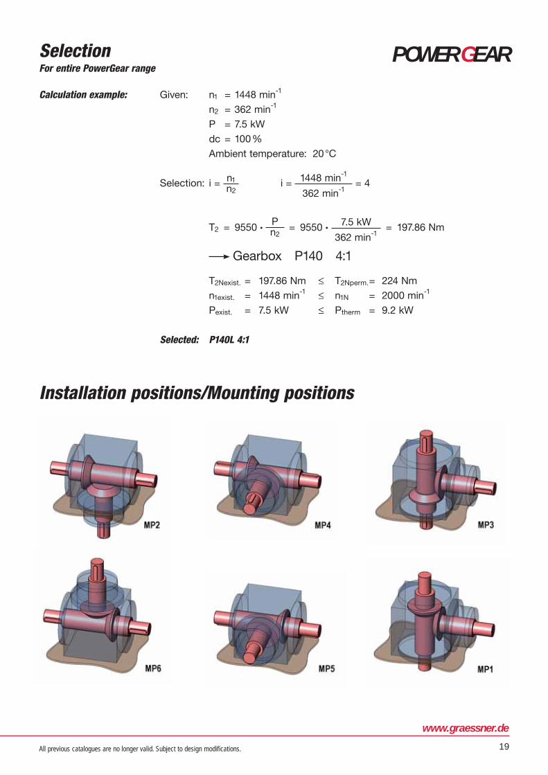
Installation positions/Mounting positions
All previous catalogues are no longer valid. Subject to design modifications.20
Options
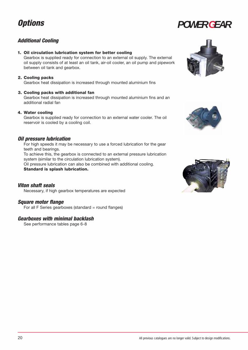
Additional Cooling
1. Oil circulation lubrication system for better cooling Gearbox is supplied ready for connection to an external oil supply. The external
oil supply consists of at least an oil tank, air-oil cooler, an oil pump and pipework
between oil tank and gearbox.
2. Cooling packs Gearbox heat dissipation is increased through mounted aluminium fins
3. Cooling packs with additional fan Gearbox heat dissipation is increased through mounted aluminium fins and an
additional radial fan
4. Water cooling Gearbox is supplied ready for connection to an external water cooler. The oil
reservoir is cooled by a cooling coil.
Oil pressure lubrication For high speeds it may be necessary to use a forced lubrication for the gear
teeth and bearings.
To achieve this, the gearbox is connected to an external pressure lubrication
system (similar to the circulation lubrication system).
Oil pressure lubrication can also be combined with additional cooling.
Standard is splash lubrication.
Viton shaft seals Necessary, if high gearbox temperatures are expected
Square motor flange For all F Series gearboxes (standard = round flanges)
Gearboxes with minimal backlash See performance tables page 6-8
POWER GEAR

www.graessner.de
21
POWER GEAR
All previous catalogues are no longer valid. Subject to design modifications.
Options
Oil filling Our gearbox sizes P54 to P140 (X75 to X14) are filled as standard with synthetic oil.
For sizes P170 to P450 (X170 to X280), oil filling requires additional ordering.
On request, we can also fill the gearboxes with food quality recognised (USDA) oil.
Shorter shafts Possible for existing shafts
Plain shafts (Without keyways) are possible
Customised designs Further customised designs available on request.
Universal mounting feet
l 3 (mm)l 4 (mm)
- 0.5l 5 (mm) l 6 (mm)
l 7 (mm)
+- 0.2
l 8 (mm)
+- 0.2Ød4 (mm)
Cylincrical
screw DIN 912
Weight per
pair (kg)
P075 122 75 40 17 108 60 6.6 M 6 x 12 0.6
P090 145 90 45 17 125 72 6.6 M 6 x 12 0.8
P110 168 110 50 17 146 88 9.0 M 8 x 18 1.1
P140 208 140 60 20 178 110 11.0 M 10 x 25 1.9
P170 250 170 70 20 215 134 14.0 M 12 x 25 2.7
P210 310 210 90 25 265 170 18.0 M 16 x 35 5.2
P240 345 240 100 30 295 190 18.0 M 16 x 35 8.0
P280 385 280 100 30 335 220 18.0 M 16 x 35 9.6
P360 480 360 125 30 430 280 22.0 M 20 x 40 15.0
P450 580 450 140 30 520 350 22.0 M 20 x 40 21.2

All previous catalogues are no longer valid. Subject to design modifications.22
POWER GEAR
Size P54 P75 / X75 P90 / X90 P110 / X110 P140 / X140 P170 / X170 P210 / X210 P240 / X240 P280 / X280 P360 P450
Average 0,05 l 0,1 l 0,2 l 0,3 l 0,4 l 1,0 l 2,2 l 2,6 l 3,0 l 9,0 l 22,0 lmax amount of oil
– – – 0,35 l 0,6 l 1,2 l 2,5 l 3,5 l 5,0 l 15,0 l 32,0 l
Oil quantities (dependent on ratio, speed, shaft arrangement and installation position)
LubricationRecommendation for MS-Graessner Gearboxes
Lubricant
Speed
up to/ above
min-1
Viscosity Product
ISO VG
DIN 51519
at 40 °C
(mm²/s)
CastrolCastrol
performanceShell Mobil Klüber
Mineral oils
500 VG 220 Alpha SP 220Optigear EP 220
Tribol 1100 / 220
Shell Omala F220
Shell Omala 220
Mobilgear
600 XP 220
Klüberoil
GEM 1-220 N
1000 VG 150 Alpha SP 150Optigear EP 150
Tribol 1100 / 150
Shell Omala F150
Shell Omala 150
Mobilgear
600 XP 150
Klüberoil
GEM 1-150 N
1500 VG 100 Alpha SP 100Optigear EP 100
Tribol 1100 / 100
Shell Omala F100
Shell Omala 100
Mobilgear
600 XP 100
Klüberoil
GEM 1-100 N
above 2000 VG 68 Alpha SP 68 Shell Omala 68Mobilgear
600 XP 68
Klüberoil
GEM 1-68 N
Mineral oils for
hypoid drives
up to 2000SAE category
85W-90
Mobilube
HD-A 85W-90
above 2000SAE category
80W
Mobilube
GX-A 80W
Synthetic gear oil
Polyglycols
(CLP-PG)
500 VG 220**Alphasyn
GS 220**Tribol 800 / 220
Shell Tivela S 220
Shell Cassida WG 220Mobil Glygoyle 30
Klübersynth
GH 6-220
1000 VG 150**Alphasyn
GS 150**Tribol 800 / 150
Shell Tivela S150
Shell Cassida WG 150Mobil Glygoyle 22
Klübersynth
GH 6-150
start at 2000 VG 100 **Tribol 800 / 100 Mobil Glygoyle 11Klübersynth
GH 6-100
Synthetic gear oil
Poly-a-Olefine
(CLP-HC)
500 VG 220 *Alphasyn EP 220*Optigear Synthetic
PD 220Shell Omala HD 220
Mobil SHC 630
Mobil SHC Gear
220
Klübersynth
GEM 4-220 N
1000
(3000)VG 150 *Alphasyn EP 150
*Optigear Synthetic
PD 150Shell Omala HD 150
Mobil SHC 629
Mobil SHC Gear
150
Klübersynth
GEM 4-150 N
1500 VG 100 Mobil SHC 627
start at 1500 VG 68 Mobil SHC 626
Physiologically
uncritical oils
(PHY-Oil)
USDA - H1
Certified
NSF H1
Certified
1000 VG 220
*Optileb GT 220
**Tribol FoodProof
1800 / 220
Shell Cassida WG 220Mobil SHC
Cibus 220
*Klüberoil
4 UH1 – 220 N
**Klübersynth
UH1 6-220
1500 VG 150 *Optileb GT 150Mobil SHC
Cibus 150
*Klüberoil
4 UH1 – 150
**Klübersynth
UH1 6-150
start at 1500 VG 100 *Optileb GT 100Mobil SHC
Cibus 100
*Klüberoil
4 UH1 - 68 N
* Synth. KW-Oil, Ester Oil ** Polyglycol Oil
When changing oil, we recommend that you fill the gear unit with the type of oil previously used. In
particular, synthetic oils may not be mixed with mineral oils or other synthetic oils. When changing from
mineral oil to synthetic oil, the gearbox must be rinsed thoroughly with new oil type.

All previous catalogues are no longer valid. Subject to design modifications.
www.graessner.de
23
POWER GEARTechnical service and maintenancePOWERGEAR gearboxes, size P75 to P140 and X75 to X140 are supplied ready lubricated for life with a
high-quality Poly-Alpha-Olefin synthetic oil. They are therefore maintenance free. Up to size P110/X110
there are no oil drain holes included. Only from size P140/X140 do the gearboxes include oil drain holes
to enable optional oil changes.
POWERGEAR gearboxes, size P170 to P450 and X170 to X280 are supplied without lubricant if not
ordered additionally.
For operating temperatures of max 80 °C, we recommend the use of mineral gear oil CLP DIN 51517 to
ISO VG-Class 100 (DIN 51519).
For operating temperatures of up to 90 °C, we recommend the use of Poly-Alpha-Olefin synthetic gear
oil CLP DIN 51517, part 3, to ISO VG-Class 150 (DIN 51519).
The lifespan of the oil at 80 °C average temperature in the gearbox without any relevant change in the
quality of the oil, indicated by the oil producers are maximum values:
– for mineral oils, biodegradable oil and physiologically uncritical oil at least 2 years or 10.000
operating hours
– for Poly-Alpha-Olefine and Polyglykole at least 4 years or 20.000 operating hours
Please note:
The actual lifespan may be longer but for temperatures of over 80 °C could equally be shorter. As a rule,
the lifespan of the oil is reduced by 50% for an operating temperature increase of 10%.
The condition of the gearbox and especially the leak tightness requires checking at regular intervals.
Service kits of wear and tear parts with full instructions are available from our service department.

All previous catalogues are no longer valid. Subject to design modifications.24
POWER GEAROrdering Example
P 075 L 1,00:1 Wa. 1
1. 2. 3. 4. 5.
1. Gearbox range P = PowerGear Standard Page 6 + 7 X = PowerGear Reinforced Design Page 8
1. Size Page 6 -8
3. Series L – Solid shaft Page 10 + 12 / Page 16 FL – Solid shaft with flange Page 14 H – Hollow shaft Page 11 + 13 / Page 17 FH – Hollow shaft with flange Page 15
4. Ratio Page 6 -8
5. Shaft arrangement Page 10 – 17
6. Additional data • Installation Position Page 19• Input speeds
Maximum application speedfor FL / FH Series, please indicate
d1, flange version B5 or B14 and flange diameter Page 14+ 15
• Options – on request Page 20 + 21 • Customised design – on request
6.
Please note thatAll Information contained in this catalogue is provided without guarantee and is not binding. In parti-cular, dimensions and values only provide guidance. Any exact, specific requirements must be agreed with us. Specifications and features listed in the catalogue are subject to a written contract.

www.graessner.de
25
POWER GEAR
All previous catalogues are no longer valid. Subject to design modifications.

All previous catalogues are no longer valid. Subject to design modifications.

www.graessner.de
Further information regarding the distribution network of MS-GRAESSNER can be found on:
www.graessner.com
Germany
MS-GRAESSNER GmbH & Co. KGTHE GEAR COMPANYKuchenäcker 11
72135 Dettenhausen
Tel.: +49 (0) 71 57 123-0
Fax: +49 (0) 71 57 123-212
E-Mail: [email protected]
www.graessner.de
Austria
GRAESSNER GmbHPerfektastraße 61
Objekt 6 / 2
1230 Wien
Tel.: +43 (1) 699 24 30-0
Fax: +43 (1) 699 24 30-20
E-Mail: [email protected]
www.graessner.at

MS-Graessner GmbH & Co. KG THE GEAR COMPANY
MS-Graessner GmbH & Co. KG . Kuchenäcker 11 . 72135 Dettenhausen / Germany
Tel.: +49 (0)71 57 123-0 . Fax: +49 (0)71 57 123-212 . E-Mail: [email protected] . www.graessner.de
2014
–07
Id.
10
00
DK
00
05
4
The bevel helical gearbox
■ Two-stage bevel helical gearbox with ratios of up to 75:1
■ Torques up to 7500 Nm ■ Torsional backlash < 6 arcmin■ Compact design■ Motor mounting either directly or
via flange and coupling■ High torsional stiffness ■ High input speeds at high
torques
KS TWIN GEAR
The highly dynamic servo right angle gearbox
■ Hypoid gearing■ High input speeds at medium to
high torques■ Ratios single-stage
i = 3:1 to 30:1■ Ratios, two-stage , up to 150:1■ Torques up to 1440 Nm■ Flexible motor mounting via flange
and coupling ■ Low backlash < 2 arcmin ■ Variable ratios and uniform
dimensions
Spiral, Hypoid and Zerol Bevel Gears
■ Standard range of products and custom-made versions
■ Module ms from 0.5 to 12 ■ Diameters up to 410 mm■ Shaft angles from 10° to 170° ■ More than 50 years of experience■ In-house gearing calculations ■ We manufacture to your drawing or
advise you of possible alternatives■ Milled or ground gear tooth cutting
The high performancebevel gearbox
■ High torque, small size ■ For medium input speeds■ Ratios from i = 1:1 to 5:1■ Torques up to 7000 Nm ■ Output via solid and hollow shaft■ Motor mounting either directly or
via flange and coupling ■ Variable ratios and uniform
dimensions
DYNA GEAR
DESIGN GEAR
DYNA GEAR
POWER GEARBEVEL GEAR
The cost-effective servo right angle gearbox
■ Hypoid gearing ■ High input speeds at medium
torques ■ Ratios single-stage
i= 5:1, 8:1, 10:1 and 15:1■ Torques up to 260 Nm ■ Flexible motor mounting via flange
and coupling ■ Backlash < 6 arcmin ■ Variable ratios and uniform
dimensions
Economy
The customised gearbox
■ Single-stage gearbox available as gear-change or reversing gearbox
■ Forced oil circulation lubrication system gearbox for high speeds and torques
■ Labyrinth sealed gearbox with an efficiency of > 99%
■ Special gearbox with additional functional elements
■ Endless possibilities on request