power engineering society chicago chapter reactive power: sources and solutions 12 february 2003...
Post on 22-Dec-2015
217 views
TRANSCRIPT

Power Engineering SocietyChicago Chapter
Reactive Power: Sources and Solutions12 February 2003
David E. Mertz, PEBurns & McDonnell Engineers, Inc

Reactive Power
• What is it?– Current that is 90 degrees out of phase with
the voltage in an alternating current system.– Inherent in all alternating current systems– Caused by capacitive (leading) and inductive
(lagging) loads.– The complement of “real” power.

Reactive Power
• Where does it come from?– All conductors are an inductor.
– Multiple conductors are inductors with a mutual capacitance.
Reactive Power
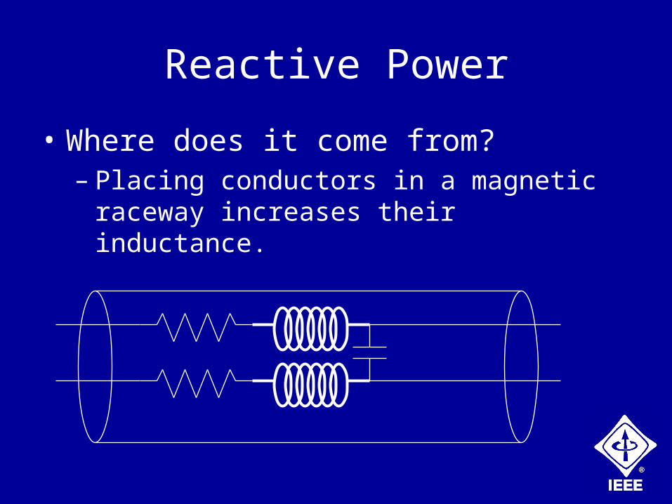
• Where does it come from?– Placing conductors in a magnetic raceway
increases their inductance.
Reactive Power
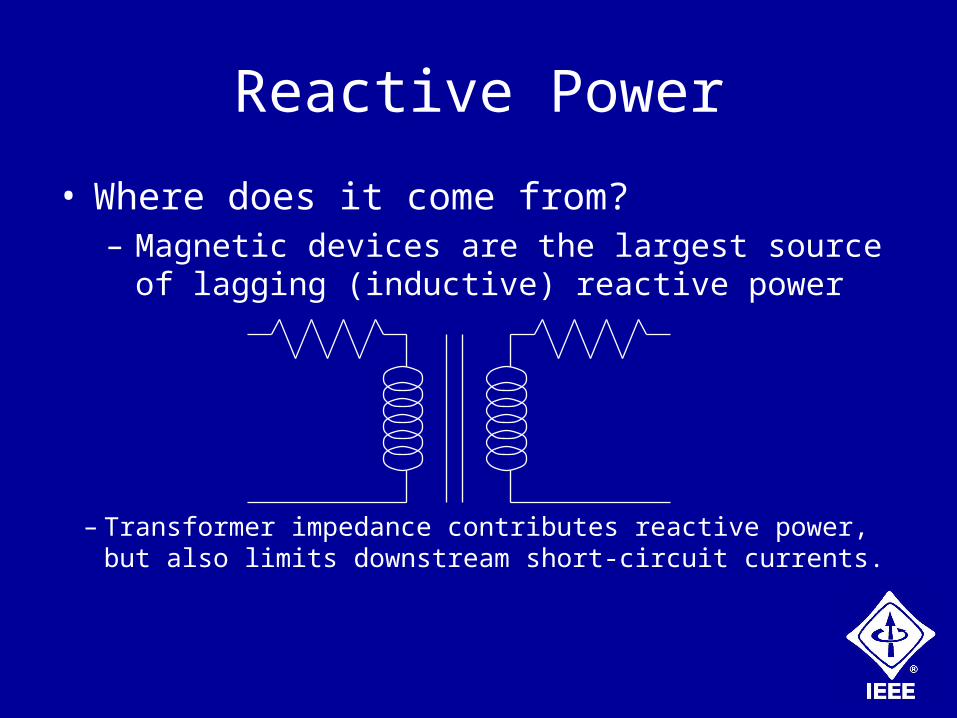
• Where does it come from?– Magnetic devices are the largest source of lagging
(inductive) reactive power
– Transformer impedance contributes reactive power, but also limits downstream short-circuit currents.

Reactive Power
• Where does it come from?– Magnetic devices are the largest source of lagging
(inductive) reactive power
– Magnetic lamp ballasts also produce lagging reactive power.
Reactive Power
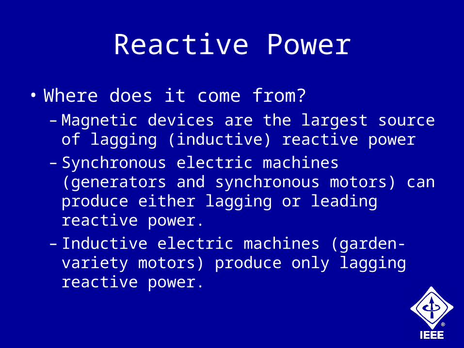
• Where does it come from?– Magnetic devices are the largest source of
lagging (inductive) reactive power– Synchronous electric machines (generators
and synchronous motors) can produce either lagging or leading reactive power.
– Inductive electric machines (garden-variety motors) produce only lagging reactive power.

Reactive Power
• What good is it?– In small amounts, it helps transmission line
operators control the flow of electric power.– The transmission of high-frequency or step
signals in power systems is greatly attenuated by the properties that also give us reactive power.
– The same electrical phenomena are used to tune circuits for transmitting and receiving signal broadcast at selected frequencies
• Why is it not desirable?– Transmitting reactive together with real power
power reduces the conductor ampacity, transformer capacity, and generator capacity available for the real power.
– It can lead to the overheating of electrical transmission and distribution equipment.
– The same electrical phenomenon attenuates signals on wire-based systems.
Reactive Power

Reactive Power
• How do we control it?– Limit the amount of lagging reactive power
required from the electrical power system.– The single largest controllable source of
lagging (inductive) reactive power is:
Reactive Power
• How do we control it?– The single largest controllable source of
lagging (inductive) reactive power is:
LAZY
MECHANICAL
ENGINEERS
Reactive Power
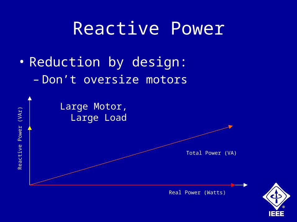
• Reduction by design:– Don’t oversize motors
Real Power (Watts)
Rea
ctiv
e P
ower
(V
Ar)
Total Power (VA)
Large Motor, Large Load

Reactive Power
• Reduction by design:– Don’t oversize motors
Real Power (Watts)
Rea
ctiv
e P
ower
(V
Ar)
Total Power (VA)
Large Motor, Small Load

Reactive Power
• Reduction by design:– Don’t oversize motors
Real Power (Watts)
Rea
ctiv
e P
ower
(V
Ar)
Total Power (VA)
Small Motor, Small Load
Reactive Power
• Reduction by design:– Select high power factor motors
• These are often high efficiency motors• Be aware that high power factor motors often have
higher starting current requirements.• Ensure that the high efficiency or high power factor
motors have the right mechanical characteristics, such as starting torque, for the load.

Reactive Power
• Reduction by design:– Use variable frequency drives (VFDs) where
applicable• Power factor on line side of VFD is usually 0.95 or
greater.• Reactive power reduction alone won’t justify cost
of the drive, but can be part of the total return on investment.
• VFDs have rectifier front ends, which will add harmonic currents to the system.

Reactive Power
• Reduction by design:– Use synchronous motors for large, constant
speed and load applications• Synchronous motors can be run as a source of
leading as well as lagging power factor• A large, constant load is necessary to be able to
recover the added cost of the synchronous motor and its field controller.
• Typically applied at higher voltages (4160, 13 800).

Reactive Power
• Reduction by design:– Carefully select lighting ballasts
• Where possible, use electronic ballasts• Otherwise, select high power factor ballasts.• When using electronic ballasts, be aware of third
harmonic consideration.
Reactive Power
• Lagging power factor countermeasures:– Reduce the demand for reactive power
through the measures previously mentioned.• Reducing the amount of lagging reactive power on
a system has less potential for creating undesirable conditions than trying to correct it through adding sources of leading reactive power.
• Reducing reactive power demand will almost always reduce the real power demand also.
Reactive Power
• Lagging power factor countermeasures:– Add sources of leading reactive power once
opportunities to reduce lagging power demand have been addressed.
• Once leading reactive sources have been added to a power system, tuned “LC” circuits have been created. Potentially severe and difficult-to-diagnose harmonic current flows can result if the resonant frequency or frequencies coincide with the fundament or system frequency or its harmonics.
Reactive Power
• Lagging power factor countermeasures:– Distribution-level Fixed Capacitors:
• Most economical on a dollars-per-farad basis.• No control system required• Least flexible in response to changing system
conditions.
– Load-level Fixed Capacitors• Very economical, easy to install, no control
system, switches automatically with the load.
Reactive Power
• Lagging power factor countermeasures:– Distribution-level Switched Capacitors:
• More expensive than fixed banks, but responds to changes in reactive power demand.
• Control system required, with added cost, configuration, and maintenance required.
• Electromechanical type is less expensive than semiconductor switched banks, but it responds more slowly to load changes, which may be a concern if avoiding utility penalties is a concern.
Reactive Power
• Lagging power factor countermeasures:– Active Harmonic Compensation Systems:
• Most expensive on a dollars-per-farad basis.• Works by “injecting” compensating current into the
power system.• Highly responsive control system compensates on
a sub-cycle basis for both harmonic and reactive power demands.
• Under normal configuration, reactive power takes a back seat to harmonic cancellation.

Reactive Power
• Benefits of reactive power control:– Better voltage stability– More efficient use of existing power system.
• May be able to add load without increasing system ampacities.
– Less heating of electrical equipment• Extends useful life of equipment.• Less real power needed to generate that heat.
– Potential reduction in utility charges.

Reactive Power
• Summary:– Reactive power is inherent in AC systems and
serves some useful purposes.– Reduce demand for reactive power before
adding capacitors to compensate.– Select leading reactive power sources by
balancing cost with need for flexibility and responsiveness.
Reactive Power
• For further reading:– IEEE Std. 141-1993, Electric Power
Distribution for Industrial Plants, Chapter 8.• This is a good resource for sizing power factor
correction capacitors.
• Questions and discussion

Reactive Power
For further reading:
IEEE Std. 141-1993, Electric Power Distribution for Industrial Plants, Chapter 8. This is a good resource for sizing power factor correction capacitors.
Questions and discussion.