power end parts list
TRANSCRIPT

ECN 1040704
GARDNER DENVER® 302WPD997 Rev BApril 2008
WELL SERVICING PUMP
MODEL
GD-600
POWER END PARTS LIST

i
GD-600 WELL SERVICING PUMP
MAINTAIN PUMP RELIABILITY AND PERFORMANCE WITH
GENUINE GARDNER DENVER PARTS AND SUPPORT SERVICES
Gardner Denver® genuine pump parts are manufactured to design tolerances and are developed for optimum dependability. Design and material innovations are the result of years of experience with hundreds of different pump applications. Reliability in materials and quality assurance is incorporated in our genuine replacement parts. Your authorized Gardner Denver Sales Office offers all the backup you’ll need. The Tulsa Manufacturing Facility maintains a large inventory of genuine parts. Gardner Denver supports your needs with these services: 1. Trained parts specialists to assist you in selecting the correct replacement parts.
2. Repair and maintenance kits designed with the necessary parts to simplify servicing your pump. Authorized service technicians are factory trained and skilled in pump maintenance and repair. They are ready to respond and assist you by providing fast, expert maintenance and repair services. For the location of your local authorized Gardner Denver distributor, refer to the yellow pages of your phone directory or contact:
Factory (Tulsa): Service Center (Odessa): Service Center (Ft. Worth): Gardner Denver Well Servicing Pumps 4747 South 83rd East Avenue Tulsa, Oklahoma 74145
Chaparral 2121 West 44th Street Odessa, Tx 79768
Geoquip 7533 Kathy Lane Ft. Worth, Texas 76126
Phone: (918) 664-1151 (800) 637-8099
Phone: (432) 366-5433 (800) 368-1134
Phone: (817) 249-6400 (800) 824-0271
Fax: (918) 664-6225 Fax: (432) 363-9940 Fax: (817) 249-6401
INSTRUCTIONS FOR ORDERING REPAIR PARTS When ordering parts, specify Pump MODEL and SERIAL NUMBER (see nameplate on unit). The Serial Number is also stamped on top of the cylinder end of the frame (cradle area). All orders for Parts should be placed with the Tulsa or Ft. Worth facility. Where NOT specified, quantity of parts required per pump or unit is one (1); where more than one is required per unit, quantity is indicated in parenthesis. SPECIFY EXACTLY THE NUMBER OF PARTS REQUIRED.

ii
TABLE OF CONTENTS
PARTS AND SUPPORT SERVICES ............................................................................... i LIST OF FIGURES...........................................................................................................ii POWER END ASSEMBLY.............................................................................................. 1 GEARBOX ASSEMBLY (16 Inch Offset)......................................................................... 7 GEARBOX ASSEMBLY (13 Inch Offset)....................................................................... 12 EXTERNAL LUBE ASSEMBLY..................................................................................... 17 APPENDIX “A” (Gearbox Positions – Left Hand Drive) ................................................. 19 APPENDIX “A” (Gearbox Positions – Right Hand Drive)............................................... 20 APPENDIX “B” (Warranty Policy) .................................................................................. 21
LIST OF FIGURES
Figure 1: GD-600 Power End Isometric View.................................................................. 1 Figure 2: GD-600 Power End Top View .......................................................................... 1 Figure 3: GD-600 Power End Side View ......................................................................... 2 Figure 4: GD-600 Power End Section A-A ...................................................................... 3 Figure 5: GD-600 Power End Detail D ............................................................................ 3 Figure 6: GD-600 Power End Section B-B ...................................................................... 4 Figure 7: GD-600 Power End Section C-C...................................................................... 5 Figure 8: GD-600 Power End Detail E............................................................................. 5 Figure 9: 16 Inch Offset Gearbox Assembly Front View.................................................. 7 Figure 10: 16 Inch Offset Gearbox Assembly Side View................................................. 7 Figure 11: 16 Inch Offset Gearbox Assembly Section A-A ISO View.............................. 8 Figure 12: 16 Inch Offset Gearbox Assembly Section B-B ISO View.............................. 8 Figure 13: 16 Inch Offset Gearbox Assembly Section A-A View ..................................... 9 Figure 14: 16 Inch Offset Gearbox Assembly Section B-B View ................................... 10 Figure 15: 16 Inch Offset Gearbox Assembly View D-D................................................ 10 Figure 16: 13 Inch Offset Gearbox Assembly Front View.............................................. 12 Figure 17: 13 Inch Offset Gearbox Assembly Side View............................................... 12 Figure 18: 13 Inch Offset Gearbox Assembly Section A-A ISO View............................ 13 Figure 19: 13 Inch Offset Gearbox Assembly Section B-B ISO View............................ 13 Figure 20: 13 Inch Offset Gearbox Assembly Section A-A View ................................... 14 Figure 21: 13 Inch Offset Gearbox Assembly Section B-B View ................................... 15 Figure 22: 13 Inch Offset Gearbox Assembly View D-D................................................ 15 Figure 23: GD-600 Lube Assembly, Off Drive Side ISO View ....................................... 17 Figure 24: GD-600 Lube Assembly, Drive Side ISO View............................................. 18 Figure 25: GD-600 Lube Assembly, Bottom View ......................................................... 18

1
POWER END ASSEMBLY
Order by Part Number and Description. Reference Numbers are for your convenience only.
Figure 1: GD-600 Power End Isometric View
Figure 2: GD-600 Power End Top View
Ref. Drawing 308WPD810

2
POWER END ASSEMBLY (Continued)
Order by Part Number and Description. Reference Numbers are for your convenience only.
Figure 3: GD-600 Power End Side View
Ref. Drawing 308WPD810

3
POWER END ASSEMBLY (Continued)
Order by Part Number and Description. Reference Numbers are for your convenience only.
Figure 4: GD-600 Power End Section A-A
Figure 5: GD-600 Power End Detail D
Ref. Drawing 308WPD810

4
POWER END ASSEMBLY (Continued)
Order by Part Number and Description. Reference Numbers are for your convenience only.
Figure 6: GD-600 Power End Section B-B
Ref. Drawing 308WPD810

5
POWER END ASSEMBLY (Continued)
Order by Part Number and Description. Reference Numbers are for your convenience only.
Figure 7: GD-600 Power End Section C-C
Figure 8: GD-600 Power End Detail E
Ref. Drawing 308WPD810

6
Order by Part Number and Description. Reference Numbers are for your convenience only.
POWER END ASSEMBLY
Ref. No. Name of Part Qty. Part No.
1 FRAME 1 PP1016145 2 CRANKSHAFT 1 PP1010928 3 CONNECTING ROD 3 PP1011091 4 BEARING - CONNECTING ROD 3 100108 5 BEARING - MAIN, INSIDE FLOATING 2 100111 6 BEARING - MAIN OUTER 2 VP1031608 7 CROSSHEAD 3 PP1011025 8 WRIST PIN 3 PP1028598 9 BUSHING 3 917PN01 10 RETAINING RING – CROSSHEAD PIN 6 926SH01-3 11 RETAINING RING – MAIN BEARINGS (FRAME) 4 VP1017135 12 RETAINING RING – MAIN BEARINGS (CRANKSHAFT) 4 VP1017134 13 INSPECTION PLATE - REAR 1 PP1017092 14 GASKET – REAR INSPECTION PLATE 1 PP1017129 15 BEARING HOUSING – OFF DRIVE SIDE 1 PP1016875 16 COVER – OFF DRIVE SIDE BEARING HOUSING 1 PP1017008 17 O-RING 1 VP1017132 18 SCREW – SOCKET HEAD 8 75P153 19 SCREW – HEX HEAD 38 75LM51 20 OIL SEAL 1 901SH02-13 21 RETAINER – ROTARY UNION ADAPTOR SEAL 1 342-A-75 22 BREATHER – 1” CONNECTION 1 910PN05 23 SCREW – HEX HEAD 12 75K48 24 OIL STOP HEAD 3 PP1016903 25 O-RING 3 115205 26 OIL SEAL - EXTENSION ROD 3 VP1027765 27 SCREW – HEX HEAD 18 351954 28 RETAINER – OIL STOP HEAD 6 PP1028144 29 WASHER – PLAIN 18 95A3 30 INSPECTION PLATE – TOP 1 PP1017282 31 EXTENSION ROD 3 285PN004 32 ROTARY UNION 1 922PN01 33 ADAPTER – ROTARY UNION 1 342-A-74 34 PLUG – CRANKSHAFT LUBE 1 PP1017167 35 SCREW – SOCKET HEAD 8 454VP034-006 36 O-RING 2 901SH05-223

7
GEARBOX ASSEMBLY (16 Inch Offset)
Order by Part Number and Description. Reference Numbers are for your convenience only.
Figure 9: 16 Inch Offset Gearbox Assembly Front View
Figure 10: 16 Inch Offset Gearbox Assembly Side View
Ref. Drawing 309WPD810

8
GEARBOX ASSEMBLY (16 Inch Offset) (Continued)
Order by Part Number and Description. Reference Numbers are for your convenience only.
Figure 11: 16 Inch Offset Gearbox Assembly Section A-A ISO View
Figure 12: 16 Inch Offset Gearbox Assembly Section B-B ISO View
Ref. Drawing 309WPD810

9
GEARBOX ASSEMBLY (16 Inch Offset)
(Continued)
Order by Part Number and Description. Reference Numbers are for your convenience only.
Figure 13: 16 Inch Offset Gearbox Assembly Section A-A View
Ref. Drawing 309WPD810

10
GEARBOX ASSEMBLY (16 Inch Offset) (Continued)
Order by Part Number and Description. Reference Numbers are for your convenience only.
Figure 14: 16 Inch Offset Gearbox Assembly Section B-B View
Figure 15: 16 Inch Offset Gearbox Assembly View D-D
Ref. Drawing 309WPD810

11
Order by Part Number and Description. Reference Numbers are for your convenience only.
GEAR BOX ASSEMBLY 16 Inch Offset
Ref. No. Name of Part Qty. Part No.
1 DRIVEN GEAR 1 PP1018969 2 DRIVER (PINION) GEAR 1 PP1018971 3 MAIN SHAFT 1 PP1019007 4 COUPLING 1 PP1018933 5 SPACER 1 PP1018934 6 GEAR HOUSING 1 PP1018972 7 RETAINER PLATE – HIGH SPEED 1 PP1018935 8 SPRAY BAR 2 PP1018973 9 TUBE ASSEMBLY 2 PP1018974 10 GASKET 3 PP1018936 11 SPACER – COMPANION FLANGE 1 PP1018937 12 SPLINE – GEARBOX DRIVE 1 PP1018938 13 RETAINER – GEARBOX DRIVE SPLINE 1 PP1018939 14 SPLINE – CRANKSHAFT DRIVE 1 PP1018940 15 RETAINER PLATE – LOW SPEED 1 PP1018941 16 RETAINER PLATE – HIGH SPEED (LUBE INLET) 1 PP1018931 17 TUBE FITTING 4 VP1019038 18 ROLLER BEARING – DRIVEN GEAR 2 VP1019033 19 KEY 1 PP1019042 20 RETAINING RING 1 VP1019045 21 ROLLER BEARING – DRIVER (PINION) GEAR 2 VP1019034 22 OIL SEAL 1 VP1019035 23 O-RING 1 25BC240 24 WASHER 18 VP1019032 25 SCREW – HEX HEAD 18 655EE080 26 DOWEL PIN 3 VP1019030 27 SCREW – HEX HEAD 11 655EF100 28 KEY 1 PP1019043 29 RETAINING RING 2 VP1031740 30 PIPE FITTING 8 VP1019037 31 ADAPTER 1 VP1019072 33 PIPE FITTING 1 VP1019040 34 SCREW – HEX HEAD 2 655EC020 * COMPANION FLANGE – SPICER 1810 1 932PN01 * COMPANION FLANGE – SPICER 1880 1 601323000 * SPACER FOR – SPICER 1880 1 PP1035284 * WASHER 1 491PN02 * SCREW-HEX HEAD 1 655EE060 * NOT SHOWN

12
GEARBOX ASSEMBLY (13 Inch Offset)
Order by Part Number and Description. Reference Numbers are for your convenience only.
Figure 16: 13 Inch Offset Gearbox Assembly Front View
Figure 17: 13 Inch Offset Gearbox Assembly Side View
Ref. Drawing 303FWB810

13
GEARBOX ASSEMBLY (13 Inch Offset)
(Continued)
Order by Part Number and Description. Reference Numbers are for your convenience only.
Figure 18: 13 Inch Offset Gearbox Assembly Section A-A ISO View
Figure 19: 13 Inch Offset Gearbox Assembly Section B-B ISO View
Ref. Drawing 303FWB810

14
GEARBOX ASSEMBLY (13 Inch Offset) (Continued)
Order by Part Number and Description. Reference Numbers are for your convenience only.
Figure 20: 13 Inch Offset Gearbox Assembly Section A-A View
Ref. Drawing 303FWB810

15
GEARBOX ASSEMBLY (13 Inch Offset) (Continued)
Order by Part Number and Description. Reference Numbers are for your convenience only.
Figure 21: 13 Inch Offset Gearbox Assembly Section B-B View
Figure 22: 13 Inch Offset Gearbox Assembly View D-D
Ref. Drawing 303FWB810

16
Order by Part Number and Description. Reference Numbers are for your convenience only.
GEAR BOX ASSEMBLY 13 Inch Offset
Ref. No. Name of Part Qty. Part No. 1 DRIVEN GEAR 1 PP1018915 2 DRIVER (PINION) GEAR 1 PP1018917 3 MAIN SHAFT 1 PP1018918 4 COUPLING 1 PP1018933 5 SPACER 1 PP1018934 6 RETAINER PLATE – HIGH SPEED 1 PP1018935 7 GASKET 3 PP1018936 8 SPACER – COMPANION FLANGE 1 PP1018937 9 SPLINE – GEARBOX DRIVE 1 PP1018938 10 RETAINER – GEARBOX DRIVE SPLINE 1 PP1018939 11 SPLINE – CRANKSHAFT DRIVE 1 PP1018940 12 RETAINER PLATE – LOW SPEED 1 PP1018941 13 GEAR HOUSING 1 PP1018927 14 TUBE ASSEMBLY 2 PP1018929 15 SPRAY BAR 2 PP1018930 17 RETAINER PLATE – HIGH SPEED (LUBE INLET) 1 PP1018931 18 TUBE FITTING 4 VP1019038 19 ROLLER BEARING – DRIVEN GEAR 2 VP1019033 20 KEY 1 PP1019042 21 RETAINING RING 1 VP1019045 22 KEY 1 PP1019043 23 ROLLER BEARING – DRIVER (PINION) GEAR 2 VP1019034 24 RETAINING RING 2 VP1031740 25 PIPE FITTING 8 VP1019037 26 SCREW – HEX HEAD 11 655EF100 27 OIL SEAL 1 VP1019035 28 PIPE FITTING 1 VP1019040 29 ADAPTER 1 VP1019072 30 DOWEL PIN 3 VP1019030 31 WASHER 18 VP1019032 32 SCREW – HEX HEAD 18 655EE080 34 O-RING 1 25BC240 35 SCREW – HEX HEAD 2 655EC020 * COMPANION FLANGE 1 932PN01 * WASHER 1 491PN02 * SCREW-HEX HEAD 1 655EE060 * NOT SHOWN

17
EXTERNAL LUBE ASSEMBLY
(Shown with left hand drive gearbox)
Order by Part Number and Description. Reference Numbers are for your convenience only.
Figure 23: GD-600 Lube Assembly, Off Drive Side ISO View
Ref. Drawing 310WPD810

18
Figure 24: GD-600 Lube Assembly, Drive Side ISO View
EXTERNAL LUBE ASSEMBLY (CONTINUED)
(Shown with left hand drive gearbox)
Order by Part Number and Description. Reference Numbers are for your convenience only.
Figure 25: GD-600 Lube Assembly, Bottom View
LUBE ASSEMBLY Ref.
No. Name of Part Qty. Part No.
1* ROTARY UNION 1 922PN01 2* ADAPTER – ROTARY UNION 1 342-A-74 3* PLUG – CRANKSHAFT LUBE 1 PP1017167 4* SCREW – SOCKET HEAD 8 454VP034-006 5* O-RING 2 901SH05-223 6 HOSE ASSEMBLY 6 082277 7 HOSE ADAPTER 6 29Z205 8 HOSE ADAPTER 6 119113 9 PIPE NIPPLE 2 63F1 10 PIPE TEE 2 64G6 11 PIPE PLUG 2 64AA7 12 HOSE ADAPTER 2 29Z225 13 HOSE ASSEMBLY 2 100063 14 HOSE ADAPTER 2 29Z212 15 HOSE ASSEMBLY 1 301FWD2036
Ref. Drawing 310WPD810

19
APPENDIX “A” (Gearbox Positions – Left Hand Drive)
20
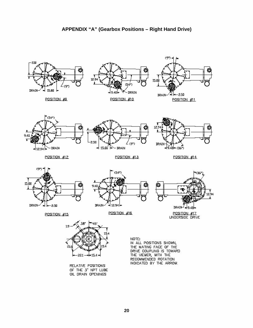
APPENDIX “A” (Gearbox Positions – Right Hand Drive)

21
APPENDIX “B” (Warranty Policy)
PRODUCT WARRANTY GARDNER DENVER PETROLEUM PUMPS
GENERAL PROVISIONS AND LIMITATIONS
Gardner Denver (the "Company") warrants to each original retail purchaser ("Purchaser") of its new products, assemblies or parts from the Company or its authorized distributors that such products are, at the time of delivery to the Purchaser, made with good material and workmanship. No warranty is made with respect to:
1. Any product which has been repaired or
altered in such a way, in the Company's judgment, as to affect the product adversely.
2. Any product which has, in the Company's judgment, been subject to negligence, accident, or improper storage, improper installation, operation or application. (Examples: over-pressure, sand-outs, cavitation, corrosion, erosion or degradation).
3. Any product which has not been operated or maintained in accordance with the recommendations of the Company.
4. Components or accessories manufactured, warranted and serviced by others.
5. Any reconditioned or prior owned product.
Claims for items described in (4) above should be submitted directly to the manufacturer. WARRANTY PERIOD
The Company's obligation under this warranty is limited to repairing or, at its option, replacing, during normal business hours at an authorized service facility of the Company, any part or assembly which in the Company’s judgment proved to have unsatisfactory material or workmanship within the applicable Warranty Period as follows.
Except for the products or components listed below, and subject to the limitations and restrictions set forth in the “Disclaimer” section set forth below, the Warranty Period for all products is 1,250 hours of operation or three (3) months after start-up, not to exceed 120 days after delivery to Purchaser, whichever occurs first. The exceptions are as follows:
1. Power end is warranted for twelve (12) months from date of start-up or eighteen (18) months from
date of delivery to the Purchaser, whichever occurs first.
2. Forged steel fluid cylinders are warranted for materials and workmanship for 6 months from the date of installation or 18 months from the date of delivery to the purchaser, which ever occurs first.
3. Repairs are warranted for 90 days from the date of delivery, for the workmanship and materials of the new parts installed.
4. Weld repaired fluid ends and weld repaired components are not warranted.
5. Expendable fluid end parts, including, but not limited to, valves, valve parts, packing, liners and pistons, are not covered by this warranty due to variable abrasive nature of material pumped.
PRESERVATION ASSEMBLIES DESTINED FOR STORAGE
In order for warranty acceptance any pump assembly not immediately installed or destined to be in storage or in transit for extended periods of time must be prepared for storage as defined in the Company’s Long Term Storage Procedure. This includes but is not limited to:
Drain and thoroughly clean inside power end
crankcase. Spray rust inhibiting oil on all bearing, machined
and inside surfaces of the power end. Induce clean gear oil into any circulating pump,
filter, heat exchanger and piping. Remove valves, seats and plungers from the fluid
end. Thoroughly clean and dry these parts and all internal surfaces. Coat all cylinder bores, valve covers and reusable expendable parts with rust preventative.
Flush all water, and contaminants from pump, tanks, hoses and spray nozzles. Spray all components with a rust inhibiting oil.
Rotate pump every 30 days to insure bearings are oiled.
At the expense of the Purchaser, any product properly preserved must be inspected by an authorized agent of the Company, prior to the Company, granting any extended warranty beyond that stated in this warranty.
BE-13 R 10/2003 Copyright © 2003 Gardner Denver, Inc. Page 1 of 2

22
APPENDIX “B” (Warranty Policy, Continued)
PRODUCT WARRANTY GARDNER DENVER PETROLEUM PUMPS LABOR TRANSPORTATION AND INSPECTION
The Company will provide labor, by Company representative or authorized service personnel, for repair or replacement of any product or part thereof which in the Company's judgment is proved not to be as warranted. Labor shall be limited to the amount specified in the Company's labor rate schedule. Labor costs in excess of the Company rate schedules caused by, but not limited to, location or inaccessibility of the equipment, or labor provided by unauthorized service personnel is not provided for by this warranty.
All costs of transportation of product or parts claimed not to be as warranted and, of repaired or replacement parts to or from such service facility shall be borne by the Purchaser. The Company may require the return of any part claimed not to be as warranted to one of its facilities as designated by the Company, transportation prepaid by the Purchaser, to establish a claim under this warranty.
Replacement parts provided under the terms of this warranty are warranted for the remainder of the Warranty Period of the product upon which installed to the same extent as if such parts were original components.
The Company may request a root cause analysis be performed in-order to identify if a request for warranty claim meets the requirements of this warranty. DISCLAIMER
Except as to title, the foregoing warranty is the sole and exclusive warranty of the Company. The Company hereby extends other manufactures’ warranty or guaranties, if any given to Company by such manufacturer, but only to the extent the Company is able to enforce such warranty or guaranties. The Company has not authorized any party to make any representation or warranty other than as expressly set forthherein. SELLER HEREBY DISCLAIMS AND EXCLUDES ANY OTHER EXPRESS, IMPLIED OR STATUTORY WARRANTIES, ARISING BY OPERATION OF LAW OR OTHERWISE, INCLUDING, WITHOUT LIMITATION, ANY WARRANTIES OF MERCHANTABILITY OR FITNESS FOR A PARTICULAR PURPOSE. COMPANY MAKES NO WARRANTIES OR REPRESENTATIONS OF ANY KIND WHATSOEVER (EXPRESS, IMPLIED OR STATUTORY), OF LAW OR OTHERWISE, ON ANY EQUIPMENT, COMPONENT PARTS OR
ACCESSORIES SOLD HEREUNDER WHICH, ARE NOT MANUFACTURED BY COMPANY.
NOTWITHSTANDING ANYTHING HEREIN TO THE CONTRARY, THE FOREGOING WARRANTY SHALL BE THE SOLE AND EXCLUSIVE REMEDY AVAILABLE TO THE PURCHASER. UNDER NO CIRCUMSTANCES, WHETHER IN CONTRACT, TORT OR OTHERWISE, SHALL THE COMPANY’S TOTAL LIABILITY ARISING IN CONNECTION WITH ANY PURCHASE ORDER EXCEED THE AMOUNT OF ANY SALES OR OTHER PROCEEDS RECEIVED PURSUANT THERETO. IN ADDITION, UNDER NO CIRCUMSTANCES, WHETHER IN CONTRACT, TORT OR OTHERWISE, SHALL THE COMPANY BE LIABLE FOR LIQUIDATED, SPECIAL, INDIRECT, INCIDENTAL, EXEMPLARY, OR CONSEQUENTIAL DAMAGES, EXPENSES OR COSTS, INCLUDING, WITHOUT LIMITATION, LOST PROFITS OR FACILITY DOWNTIME, HOWEVER CAUSED AND EVEN IF THE POTENTIAL OF SUCH DAMAGES WAS DISCLOSED AND/OR KNOWN.
No statement, representation, agreement, or understanding, oral or written, made by any agent, distributor, representative, or employee of the Company which is not contained in this Warranty will be binding upon the Company unless made in writing and executed by an officer of the Company.
This warranty shall not be effective as to any claim which is not presented within 30 days after the date upon which the product is claimed not to have been as warranted. Any action for breach of this warranty must be commenced within one year after the date upon which the cause of action occurred.
Any adjustment made pursuant to this warranty shall not be construed as an admission by the Company that any product was not as warranted.
WARRANTY REQUESTS Products to be returned for warranty analysis shall
be approved for return in writing by the Company prior to shipment. All requests for product return shall be submitted by email. Facsimile or letter to:
Warranty Department c/o Gardner Denver Petroleum Pumps 4747 South 83rd East Avenue Tulsa, Oklahoma 74145
Email: [email protected] Facsimile: (918) 664-6225
BE-13 R 10/2003 Copyright © 2003 Gardner Denver, Inc. Page 2 of 2

For additional information contact your local representative or
Gardner Denver Inc. 4747 South 83rd East Avenue, Tulsa, OK 74145 PH: (918) 664-1151, (800) 637-8099
Specifications subject to change without notice. Copyright © 2001 Gardner Denver, Inc. Litho in U.S.A.
北京
信德迈科技(北京)有限公司CNMEC Technology
北京朝阳区胜古中路2号金基业大厦201室
邮编:100029
电话:010-8428 2935 13910962635
传真:010-8428 8762
主页://www.cnmec.biz
电子邮件:[email protected]
西安
西安嘉岳自动化技术有限公司Garye Automation
地址:西安经开区凤城二路天地时代广场B座23层22312室
邮编:710016
电话:029 - 8610 8648 15319759129
传真:029 - 8610 6806
主页:http://www.garye.cn
电子邮件: [email protected]