power electronic systems as a crucial part of smart grid infrastructure
TRANSCRIPT


BULLETIN OF THE POLISH ACADEMY OF SCIENCES
TECHNICAL SCIENCES, Vol. 59, No. 4, 2011
DOI: 10.2478/v10175-011-0058-2
POWER ELECTRONICS
Power electronic systems as a crucial part
of Smart Grid infrastructure – a survey
G. BENYSEK1, M.P. KAZMIERKOWSKI2, J.POPCZYK3, and R. STRZELECKI4,5∗
1 Institute of Electrical Engineering, University of Zielona Góra, 50 Podgórna St., 65-246 Zielona Góra, Poland2 Institute of Control and Industrial Electronics, Warsaw University of Technology, 75 Koszykowa St., 00-662 Warsaw, Poland3 Institute of Power Systems and Control, The Silesian University of Technology, 2 Krzywoustego St., 44-100 Gliwice, Poland
4 Electrotechnical Institute, 28 Pożaryskiego St., 04-703 Warsaw, Poland5 Gdynia Maritime University, 81-87 Morska St. 81-225 Gdynia, Poland
Abstract. This article gives a tutorial overview of the most important issues related to the use of power electronic systems in power engi-
neering, with respect to the urgent need for modernization of existing grids in the direction of intelligent networks. The main problems and
conditions bound up with the construction of Smart Grids and the location, as well as functioning in them of the most important power
electronic systems are presented here. Special attention is directed therein to the potential possibilities of so-called ‘smart’ transformers and
V2G and V2H technologies.
Key words: power electronics, Smart Grid, converter, power control, power conditioning.
1. Introduction
Currently, at the beginning of the new decade, in the field of
power generation there are taking place such changes which
in other areas of the economy were experienced in the world
within the years 1970s and 1980s. In the meantime a funda-
mental transition has taken place from an industrial to a post-
industrial epoch – the source of national income of developed
countries has changed, namely it has been transferred from
the production sector to the services sector. Such a transition
is also currently occurring in power engineering, where the
main focus is also being transferred from the area of power
generation to the area of its distribution and management.
There are many factors, apart from EU regulations, which
accelerate the aforementioned changes in power engineering.
They are, in particular, the global growth of investments in Re-
newable Energy Resources (RES) and other Distributed Ener-
gy Systems (DES), surpassing even 40% annually [1], serving
which is the Smart Grid infrastructure itself. In Poland addi-
tional factors are also the inefficiency of large scale energy
investment, the explosive growth in production and deploy-
ment of DES and industry connected with Information and
Communication Technology (ICT), as well as the change from
a client economics base to a consumer one (prosumer). The
increasing grid failures is also a decisive factor, which stim-
ulate prosumers, boroughs, and cities into action on building
their own projects for the security of energy networks.
The aim of this article is to discuss and review the poten-
tial which the Smart Grid infrastructure brings, with particular
reference to the place, role and possibilities for the application
of power electronic systems. An additional aim is to present
selected novel solutions for devices and systems: power elec-
tronic ‘smart’ transformers and V2G and V2H technologies
intended for Smart Grids.
2. Problems, conditions and tasks
of Smart Grids
2.1. Smart Grids for social know-how or for power cor-
porations? In the context of a knowledge society Smart
Grid this means above all: micro-grids of intelligent pro-
sumers (including intelligent meters), mini-grids of boroughs,
city grids, grids for realizing new avenues of value – in-
cluding electric cars. Such a conception implies a reversal
of the method of building a Smart Grid in relation to that
which national power engineering corporations are planning.
Namely, the current national conceptions (those which the
Energy Regulatory Office and the PSE-Operator are intensely
engaged in) depend on building a ‘total’ (top-down) AMI
(Advanced Metering Infrastructure) system of measuring, in
practice only electricity, embracing all end-users (more than
16 M in Poland). Of course, one can bet that there are in-
terested parties in such a system: a) powerful interest groups
concentrated in the industry of calibration devices and data
communication, b) transmission operators and also distribu-
tion operators in the electrical energy market. On the other
hand, such a system, very expensive, but also without any
precisely defined functionality, not only gives no benefits to
consumers but has a huge potential for being transformed into
a consumer ‘pressure’ system by the operators (into a system
characterised by ‘directives’ – a so-called Big Brother syn-
drome). The risk which is here referred to is confirmed by
the Italian experience. Namely, Italy realised an AMI system
encompassing more than 30 M electrical energy consumers.
A study which was carried out with the aim of defining the
benefits of building the system show that no more than 4%
of consumers are aware of the potential possibilities of the
system (that does not mean that they have any kind of ben-
efits from it). For this reason the Polish strategy should rest
∗e-mail: [email protected]
455
G. Benysek, M.P. Kazmierkowski, J. Popczyk, and R. Strzelecki
on the building of a Smart Grid infrastructure for the needs
of prosumers, that is, for the needs of managing distributed
generation resources (moreover, polygenerational ones), and
to a lesser degree for the needs of traditional consumers.
Consequently, Poland should create a broad environment in
the area of development of precisely such an infrastructure,
in particularly with institutions which have already published
a program assisting the development of a Smart Grid (to such
institutions belong, e.g., The National Fund for Environmen-
tal Protection and Water Management, which in the coming
years will spend 500 M zloty on this purpose).
2.2. The need to rationalise the place and role of the Smart
Grid. Table 1 shows the designated areas and spheres of inter-
est for the desired place and role of the Smart Grid infrastruc-
ture. From this understanding results a need for changes in the
power system. Under no circumstances can a Smart Grid in-
frastructure serve to reinforce the character of corporate power
engineering, i.e., in particular, the role of the transmission sys-
tem operator must be restricted. The Smart Grid infrastructure
should serve the market and democracy, i.e., it should help
diverse remote development.
2.3. Smart Grid and the intensification of exploitation of
grid resources (intensification of utilization of existing elec-
trical power system). In the coming years, in Poland, there
should be one of the most important areas of exploitation of
the Smart Grid infrastructure. There are two causes justifying
such a thesis. Firstly, there are various ‘deficits’ linked with
the limitation of investments in the power system segment
(limitation of capital, location and others); these deficits will
prevent the continuation of the hitherto model of development
in the electrical power system. Secondly, there are possibili-
ties resulting from the technological delaying of the electrical
power system; as a consequence it is possible to use many
technologies/concepts for the object of intensive utilization of
these grids. The most important significance comes from the
point of view of utilization the dynamic capacity of the over-
head lines, for which purpose the basis is the identification
of the prevailing weather conditions (wind, insulation, tem-
perature), decisive for the thermal loading of the overhead
cables. In this area the role and significance of power elec-
tronic devices as controllers/conditioners of electric energy
are unquestionable.
2.4. Smart Grid and intelligent zero-energy house. Such a
house is a technology, which in conformity with the directive
2010/31/WE, concerning certification of buildings, will be in
use after 2018 in respect to new buildings for public use, and
after 2020, in respect to all buildings. To promote this tech-
nology we should already be directed to the ICT industry,
which in Poland is the fastest developing industry in Europe
and has a chance to further develop its competitiveness. Of
course, in this case it is not only restricted to measuring-
charging systems in the electric energy market. The criteria
for development in this industry must encompass such areas
as: the business of device suppliers, the reliability/quality of
the electric energy supply to traditional consumers, the value
which represents itself more than the cost of infrastructure
for prosumers, in which also counts the creation of a new life
style for them. Equally in this case it is difficult to talk about
an intelligent house without electric energy controllers, which
are power electronic devices.
2.5. Smart Grid, transport and storage technologies (elec-
tric cars). In Sec. 6 there is presented a detailed concept and
the possibilities which are gained by including electric cars in
the electric energy economy (with the help of the Smart Grid
infrastructure). Here only a short account of the characteris-
tics of the concept in two particular cases is discussed. Firstly,
a storage segment is created by electric cars, with a battery
capacity unit of about 40–60 kWh, working in charging and
driving modes. This is a segment which is developed under
the influence of the directive 2009/28/WE. If we optimistical-
ly assume that in Poland in 2020 there will be 1 M electric
cars, the storage potential of the segment (cautiously esti-
mated) comes to about 80 MWh/day (at an annual car use
of 20 000 km). This potential can be developed progressive-
ly beginning as soon as in 2012. Secondly, the storage seg-
ment created by electric cars, in the first case, but working in
the charging mode, can drive and power the grids/consumers.
Such a solution has a DSR (Demand Side Response) potential
many times bigger. There is a powerful potential in this de-
pending on the speed of car charging. Therefore also, as soon
as in future, it depends on fast charging stations and on ex-
changeable battery panels. It is estimated that in this case the
potential DSR for Poland in 2020 comes to as much as ±400
GWh/day (on the assumption that batteries can be recharged
once a day). The power electronics is of course also essential
in the exploitation of this potential.
Table 1
Place and role of Smart Grid
Designated areaSphere of interest
prosumer Local Government electric power network RES/DES prosumer
DSM individual security,comfort, consumer
economics
critical infrastructure,
balanced growth
production of devices,design, installation,franchising network
system servicesmarket at the level
of DSODG
DER
Grid resources – – –intensification of use
(basic DSO business)
Legend: DSM - Demand Side Management, DG – Distributed Generation, DSR – Demand Side Response, DSO – Distributing System Operator.
456 Bull. Pol. Ac.: Tech. 59(4) 2011

Power electronic systems as a crucial part of Smart Grid Infrastructure – a survey
3. Smart electrical energy networks
– technical concept
Over last years, Electrical Energy (EE) consumption has con-
tinually grown, on the other hand, at the same time, invest-
ment in the TD (Transmission and Distribution) infrastructure
has increasingly declined. Traditional solutions for upgrading
the electrical system infrastructure have been primarily in the
form of new power plants, new transmission lines, substa-
tions, and associated equipment. However, as experience has
proven, the process of authorizing, locating, and construct-
ing new transmission lines has become extremely difficult,
expensive and time-consuming. As a result the power grid is
under stress, resulting in compromised reliability and higher
energy costs [2]. Despite the aforementioned problems, the
system reliability is untouchable and cannot be compromised.
To overcome this problem, grid operators move away from ra-
dial systems towards networked ones, however this degrades
controllability of the network, because current flows along
particular lines cannot be easily controlled. The situation is
even worse, if a incident such as loss of a line results in
overload, increasing the possibility of a blackout. Additional-
ly, rapid load growth leads to jamming on key lines which,
in consequence, leads to an inefficient operation of energy
markets.
The answer seems to lie in transforming the current En-
ergy Power System (EPS) into smart Electrical Energy Net-
work (EEN), also called Smart Grid. Future smart EENs will
be strong, more flexible, reliable, self-healing, fully control-
lable with an asset of efficient use and will be a platform
enabling the coexistence of smart-self-controlling grids with
great amounts of Distributed Generations (DG) and large-
scale centralized power plants [3, 4]. The need for modifi-
cations, demands to remove the barriers to the large-scale
exploitation and integration of DGs and other actors, will ne-
cessitate the research, development of new innovative tech-
nologies from generation, transmission and distribution to
communication tools, with far more sensors than presently
[5]. Thus, this is envisaged that Flexible AC or DC Trans-
mission/Distribution System, Custom Power Systems (CUPS),
Energy Storage Systems (ESS) and DG, smart end-user ap-
pliances together with communications will be at the heart of
the future Smart Grids, see Fig. 1.
Fig. 1. SmartGrid with SmartMetering & SmartBuilding technology
Bull. Pol. Ac.: Tech. 59(4) 2011 457

G. Benysek, M.P. Kazmierkowski, J. Popczyk, and R. Strzelecki
Smart Grid allows the customer to take an active role in
the supply of electricity, which can help the electricity sys-
tem respond to equipment failures, weather-related emergen-
cies, and other conditions. At present, a system operator must
maintain enough excess generating capacity online or quickly
available to continue supplying system load if a large gener-
ating unit or transmission line fails. In the Smart Grids, much
of that reserve could be provided by EPS or small DG, ESS
units located near end-user sites. Summarizing, a modernized
smart grid would create EPS that:
• reduces peak loads and generate reserve margins;
• deletes capital costs of new T&D infrastructure as well as
generating plants;
• lowers T&D line losses together with operation and main-
tenance costs;
• redirects power flows, changes load patterns, improves volt-
age profiles and stability;
• enables loads ESS and DG to participate in system opera-
tions;
• through extensive monitoring, quick communications, and
feedback control of operations, it has much more informa-
tion about system rising problems before they affect ser-
vice;
• provides system utilities with advanced visualization tools
to enhance their ability to oversee the system.
4. Modern power electronics arrangements
in EEN
4.1. Application area. The use of Power Electronics (PE)
arrangements in EENs can be generally divided into: a) elec-
trical energy transmission system, b) electrical energy distrib-
ution system. The transmission system is composed basically
of two complementary technologies for controlling the trans-
mission of energy [3, 6, 7]: a) with conversion to DC current
– HVDC devices; b) directly – FACTS devices. A general
comparison of these devices is illustrated in Figs. 2 and 3.
An advantage of HVDC devices is the capability to trans-
mit energy between systems of various frequencies. However,
in the case of conventional HVDC, i.e., with the use of SCR
thyristors, it is necessary to use large filters and there is no
possibility of supplying power to end-users on the side from
which the source is disconnected. This drawback does not oc-
cur when using modern devices, such as GTO thyristors or
IGBT transistors. Here, one should note that with HVDC de-
vices the entire energy from one system flows into the other
through converters. As a result of this the cost is high, even in
single-station installations. While in FACTS devices, such as:
• SVC (Static Var Compensator) and STATCOM (Static Syn-
chronous Compensator),
• TCSC (Thyristor Controlled Series Compensator), TSSC
(Thyristor Switched Series Compensator) and SSSC (Stat-
ic Synchronous Series Compensator),
• SPS (Static Phase Shifter),
• UPFC (Unified Power Flow Controller),
only part of the power flows through the power converter.
Such devices can be applied, however, to the control of EE
flow only in AC systems with a single frequency.
Fig. 2. PE arrangements in DC transmission systems
Fig. 3. PE arrangements in AC transmission systems
A decidedly greater variety of PE arrangements oc-
curs in distribution systems. In these systems PE convert-
ers/controllers are applied in general to:
• matching parameters and coupling of distributed sources
with power lines or local end-users, and controlling con-
sumption of EE with these sources (Fig. 4),
• matching parameters and coupling of energy storage with
power lines, and controlling the exchange of energy be-
tween storage systems and power lines (Fig. 5),
• improving the quality of the power supply, among oth-
er things: compensation of sags and swells, asymmetry
and distortions of supply voltage, as well as compensation
for distortion, asymmetry and phase shift in load current
(Fig. 5).
Fig. 4. PE arrangements in alternative generation systems
458 Bull. Pol. Ac.: Tech. 59(4) 2011

Power electronic systems as a crucial part of Smart Grid Infrastructure – a survey
Fig. 5. PE arrangements in storage systems
4.2. Examples of application. Figure 6 illustrates the most
important areas of use of PE arrangements in EEN, at vari-
ous levels of power. A further discussion of these areas, with
reference to objects of this paper and common characteristics
of applied solutions, are limited to:
• wind installations,
• energy storage and of low-voltage sources,
• network couplers and installations improving energy qual-
ity.
4.3. Wind installations. The most frequent application of
PE arrangements in wind installations is in generators (Fig. 7)
[8, 9]. In the beginning the most commonly applied device
was the squirrel cage induction machine (IM) connected di-
rectly to an EEN, and PE arrangements used solely in a simple
connection-starting device. As a result, in such installations
there occurs a transfer of the pulsation of the wind power to
the power network and, moreover, there is no means of direct
control of the active and passive power. The significance of
such a control, desirable for the control of voltage and fre-
quency in an EEN, increases along with the rise in power [10].
As a result of this, generators with squirrel cage induction ma-
chines connected directly to an EEN are sporadically applied
to new installations of large power. On account of power loss-
es and limited means of regulation, generators with Wound
Rotor Induction Machines (WRIM) and PE adjustable resis-
tance in the rotor circuit are also rarely installed [11].
Fig. 6. Area of application of PE arrangements in EEN: 1) wind generators, 2) energy storage, 3) power supply systems from low-voltage
sources, 4) network couplers, 5) devices for improvement of energy quality, 6) devices for control of energy delivery
Bull. Pol. Ac.: Tech. 59(4) 2011 459

G. Benysek, M.P. Kazmierkowski, J. Popczyk, and R. Strzelecki
Fig. 7. Basic types of wind turbine generators: 1) with squirrel cage induction machines (a – fixed speed, b – variable speed), 2) with
wounded rotor induction machines (a – fixed speed , b – variable speed ), 3) with synchronous machines (a – external magnetized, b –
permanent magnets)
Currently in the world, mostly are used:
• Double Feed wounded rotor Induction Machines (DFIM)
with an AC-DC/DC-AC converter in the rotor circuit
(Fig. 7.2b),
• Synchronous Machines (SM) with an AC-DC/DC-AC con-
verter in the main line and an AC-DC/DC-AC converter in
the exciter circuit (Fig. 7.3a),
• Permanent Magnet Synchronous Machine (PMSM) and
AC-DC/DC-AC converter in main line (Fig. 7.3b).
There are also generators with squirrel cage induction ma-
chines (IM) but with self-excitation and an AC-DC/DC-AC
converter in the main line, designed for full power (Fig. 7.1b)
[11–15]. All these solutions, although more costly than the
ones applied at the beginning of the development of wind
power in Poland, are characterized by much better regulatory
qualities, among which are: the capability of adjusting active
and passive power; the capability of operating at varying shaft
rotation speeds, rapid reaction to change of wind conditions
(0.5–1 ms); avoiding influence and resistance to deteriorating
quality of EE in an EEN; and the capability to work in is-
landing mode [10]. These aspects support the implementation
of the vector control method applied originally to the motor
drives [16–19], as well as the Maximum Power Point Tracking
(MPPT) algorithms enabling the full use of the available wind
energy [9, 12]. Multipolar SM and PMSM permit through this
the elimination of a mechanical transmission system, which
raises the reliability of the turbine.
Heavy duty PE converters are equally employed in wind
farms, taking care of at least a few connected turbines situated
close by. The configuration of farms is equally dependent on
the kind of generator as well as the type of converter used
and the topology of the EEN [8–10]. A typical example is the
connection of turbines with generators, shown in Fig. 8.
On a farm as shown in Fig. 8.1, having groups of turbines
with squirrel cage induction machines, the D-STATCOM (or
SVC) supplies passive power to the machine and assists in
maintaining the voltage profile in the network. Unfortunate-
ly this farm does not lend itself to individual control of the
turbine power or control of the circulating power between tur-
bines. It is equally impossible to eliminate the phenomenon of
wind power pulses from the network. The latter drawback is,
however, removed from the farm presented in Fig. 8.2, since
the DC link (AC-DC/DC-AC converter) allows the control of
not only passive power and network voltage profile, but also
the direct control of active power supplied to the network.
This solution creates also the interesting option of connecting
a farm located at a distance from the existing EPN with the
DC line.
460 Bull. Pol. Ac.: Tech. 59(4) 2011

Power electronic systems as a crucial part of Smart Grid Infrastructure – a survey
Fig. 8. Typical connection of turbines with induction machines used in wind farms: 1) with passive power compensator (D-STATCOM or
SVC), 2) with common DC link to the power network, 3) with internal DC network and individual control of power, 4) with individual
control of power
An extended concept for use of DC couplers in wind
farms is illustrated in the configuration presented in Fig. 8.3.
The rectifier part of the heavy duty AC-DC/DC-AC convert-
er, Fig. 8.2, is divided into particular turbines, forming in this
way an internal DC network, as well as enabling individual
control of turbine power. In this respect it is noteworthy that
matching turbines to a DC network is significantly easier than
to an AC network, because the DC network requires only one
control parameter (amplitude), while the AC network requires
as many as three (amplitude, frequency and phase). Moreover,
dividing a DC network simplifies the connection of energy
storage devices. For this reason AC-DC/DC-AC converters
are used on farms, in general, only in such cases where they
have already been integrated into the turbine by the manu-
facturer. Most often this concerns turbines in which there are
generators with DFIM machines, Fig. 8.4, or PMSM. AC-
DC/DC-AC converters for individual turbines can be equally
justified in cases of a very high power.
4.4. Energy storage and low-voltage source systems. Ener-
gy storage, in the form of batteries, are widely used in back-up
power supplies. In such devices flywheels exploit greater pow-
er [3, 20], amassing kinetic energy. An example of a kinetic
resource, constructed in the form of a container, is shown
in Fig. 9. Quite small fast-rotating kinetic storage resources
are connected to an internal DC bus through an AC-DC con-
verter, and only then through a DC-AC converter to an AC
line. It should be emphasized that the greatest difficulty in
constructing a modern kinetic storage is tied not to power-
electronics, but to high-speed flywheel rotation technology
(60000–90000 RPM).
Batteries, flywheels and other storage, such as: water con-
tainers, hydrogen systems, heat energy storage, supercapaci-
tors, superconductive storage or compressed air tanks are also
used in distributed sources [3, 21]. The goal is to improve the
availability of these sources, i.e., the amelioration, or even
elimination of the influence of external conditions (weather)
on the power temporarily supplied to the EPN. For the connec-
tion of such resources to the network various PE arrangements
are employed.
Figure 10 illustrates an example of the exploitation of an
energy storage unit for the compensation of active power pul-
sations caused by the fluctuations of the wind energy. The
degree of compensation depends on the size and dynamic
qualities of the energy storage as well as the control algo-
rithm used [22]. This in turn has an influence on the power
of the converter, the type which is chosen with respect to
bidirectional energy flow and the kind of energy storage. For
example, for batteries it will be an AC-DC converter, and for
a flywheel with an AC motor, an AC-AC converter. The pow-
er of the converter depends, too, on its additional functions,
e.g., its passive power compensation efficiency.
Bull. Pol. Ac.: Tech. 59(4) 2011 461

G. Benysek, M.P. Kazmierkowski, J. Popczyk, and R. Strzelecki
Fig. 9. Example of a kinetic storage container
Fig. 10. Implementation of energy storage for the compensation of active power pulsations on output of wind farms
In the case of the exploitation of energy storage and low-
voltage sources, the configuration of the source and the means
of matching the voltage levels has a decisive influence on the
qualities of the chosen solution [23]. Typical examples here
would be a power supply with a photovoltaic cell (PV) and a
fuel cell (FC) [24–26], in spite of the fact that FC, in contrast
to energy storage, do not have the capability for bidirectional
energy flow.
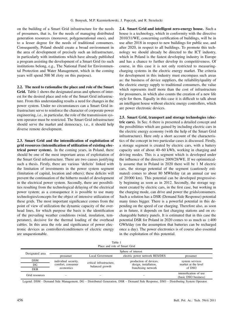
PV systems are differentiated by three basic connection
configurations, illustrated in Fig. 11. The most universal,
though at the same time the most demanding in respect to the
PE arrangement, is a configuration with a modestly sized DC-
AC converter integrated into the PV module. The converter
should be characterized by: very high efficiency and minimal
size, increased voltage cell and sinusoidal output voltage as
well as the ability to work with parallel connections. These
requirements enable the connection to modern PE converters
[27–31] realized on the basis of currently available PE com-
ponents [32–34]. In conventionally configured PV systems,
generally of greater power, an internal DC bus is frequently
used (Fig. 12). Its purpose is similar to that of the case of
the wind farm illustrated in Fig. 8.3. A DC bus also permits
easier galvanic isolation of the PV cell with the help of high
frequency transformers Fig. 12.1, and in addition, may be an
integrated part of the internal DC micro-network [35–36].
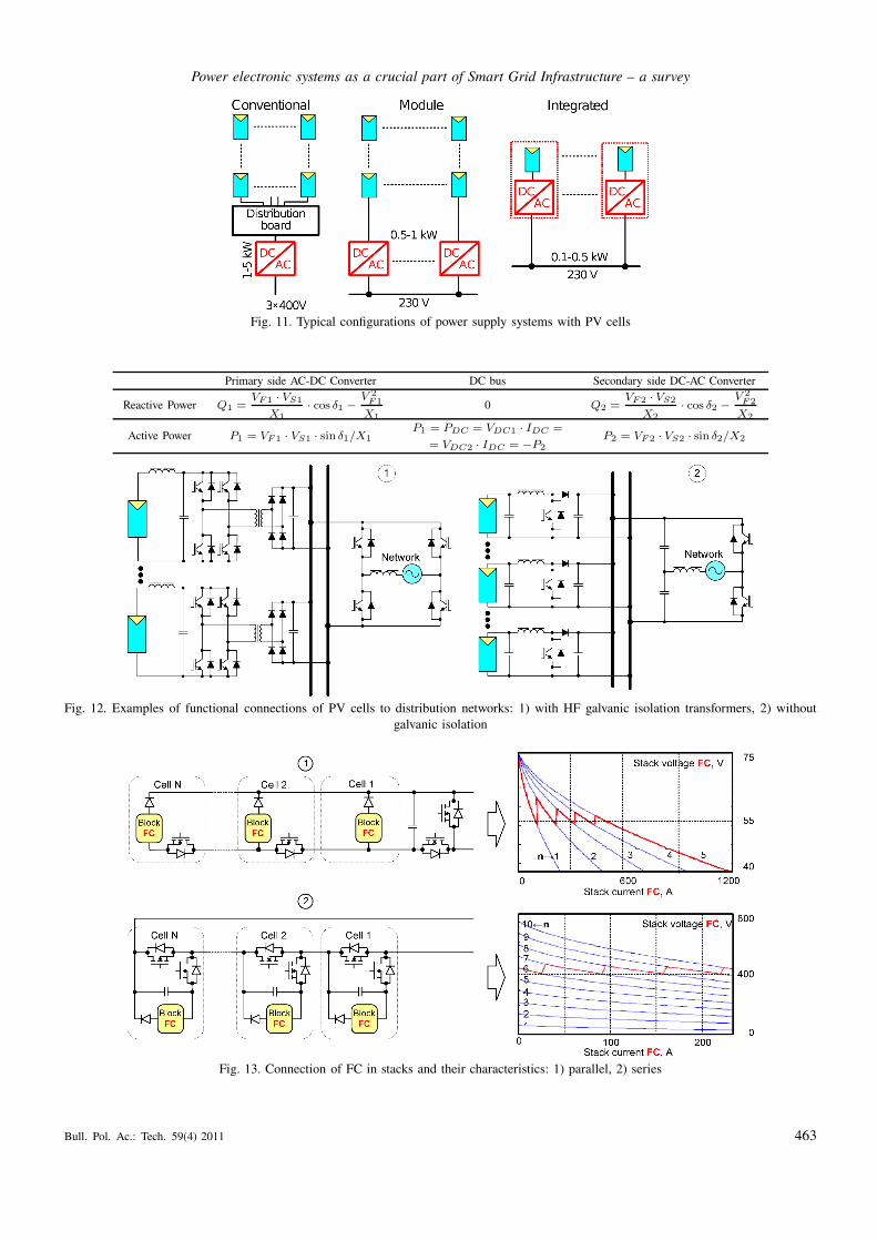
In a similar way to the PV system, with the use of a gem-
inate PI and DC bus, systems with FC elements are likewise
configured [26, 37]. In this case, taking into consideration the
soft output characteristics and low voltage of individual cells,
the connection of fuel cells in the stack is of decisive sig-
nificance to the required output voltage and load capabilities.
Figure 13 illustrates example configurations of fuel cell con-
nections in series and parallel stacks as well as current-voltage
characteristics of these stacks.
462 Bull. Pol. Ac.: Tech. 59(4) 2011
Power electronic systems as a crucial part of Smart Grid Infrastructure – a survey
Fig. 11. Typical configurations of power supply systems with PV cells
Primary side AC-DC Converter DC bus Secondary side DC-AC Converter
Reactive Power Q1 =VF1 · VS1
X1
· cos δ1 −
V 2
F1
X1
0 Q2 =VF2 · VS2
X2
· cos δ2 −
V 2
F2
X2
Active Power P1 = VF1 · VS1 · sin δ1/X1
P1 = PDC = VDC1 · IDC =
= VDC2 · IDC = −P2
P2 = VF2 · VS2 · sin δ2/X2
Fig. 12. Examples of functional connections of PV cells to distribution networks: 1) with HF galvanic isolation transformers, 2) without
galvanic isolation
Fig. 13. Connection of FC in stacks and their characteristics: 1) parallel, 2) series
Bull. Pol. Ac.: Tech. 59(4) 2011 463

G. Benysek, M.P. Kazmierkowski, J. Popczyk, and R. Strzelecki
4.5. Network couplers and power quality improvement
devices. PE network couplers and energy quality improve-
ment devices have many common features with energy de-
livery control devices. A basic difference is in the func-
tion and location of these devices in the EEN [3–7, 38–39].
The most universal couplers are “back-to-back” type devices,
composed of two fully controlled AC-DC and DC-AC con-
verters (voltage or current), connected by a DC bus [40].
While one converter works as an inverter the second acts
as a rectifier. The change in the working mode of the con-
verter causes a change in the direction of the power flow.
In so doing, always only active power flows through the
DC bus, which acts as a device insensitive to frequency and
phase differences in a coupled network. Furthermore, in re-
spect of the DC bus each converter may equally indepen-
dently fulfill additional functions as an EE quality improve-
ment device, and, in the case of connecting energy storage,
as a source of “interventional” power [2, 38, 39]. The ba-
sic function of a “back-to-back” coupler, where voltage con-
verters are used, is clarified by the explanatory phasor di-
agrams shown in Fig. 14 and the dependencies, are shown
below.
In practice “back-to-back” couplers are connected to net-
works by transformers [41–44]. Such connections serve, above
all, matching the voltage in the AC-DC/DC-AC converters and
in the network couplers. Employing transformers is also rec-
ommended in voltage matched “back-to-back” devices, e.g.,
when using multi-level converters [45, 46]. In this case, thanks
to galvanic separation, the operational safety is increased and
malfunctions are ameliorated. Moreover, transformers in par-
allel “back-to-back” devices enable improvement of the volt-
age form at the coupler’s terminals [44, 47].
Modern PE arrangements serving to couple AC and/or
DC networks as well as to match distributed sources and en-
ergy storage already today enable the building of local micro-
networks as a part of an smart EEN [3, 35, 36, 48]. For
example if we consider the micro-network structure shown in
Fig. 15, we gain a highly flexible integration of distributed
sources and the capability of “plug-and-play” type functions
at every level, without the necessity of implementing non-
standard solutions. Here it is understood that the most effec-
tive working conditions of the power network (with a micro-
network in it) occur in the case of steady loads with a power
coefficient of λ ≈1.
Fig. 14. Structure and working principle of “back-to-back” network coupler with intermediate direct current bus
Fig. 15. Hierarchical structure of hybrid micro-networks with DC and AC couplers
464 Bull. Pol. Ac.: Tech. 59(4) 2011

Power electronic systems as a crucial part of Smart Grid Infrastructure – a survey
With the aim of improving the coefficient λ < 1, on the
output or directly on the input (load), various compensatory-
filter devices are installed. Among the implemented solutions
[3, 39], the most universal are active power filters (APF) [20,
49]. APF devices, depending on the control algorithm, enable
a connection or selective compensation of all undesirable cur-
rent components and/or voltage.
Figure 16 illustrates two basic APF devices: parallel (P-
APF/Parallel-APF) and series (S-APF/ Series-APF). The P-
APF device, Fig. 16.1 is primarily intended for current com-
pensation, and the S-APF device, Fig. 16.2, for voltage com-
pensation. Sometimes the S-AFP device is also used to force
a desired current, and the P-APF device to force a desired
voltage. The choice of APF device and its use depends on
the character of the load and the network, as well as on
the demands concerning EE quality. In some cases, in or-
der to achieve the required quality of EE, it is necessary to
use series-parallel APF devices (Fig. 17). These devices, also
called UPQC (Unified Power Quality Conditioner) [49–51],
are in general constructed as integrated P-APF and S-APF
connections with a common DC bus. The device in Fig. 17.3
does not have a common DC bus [52], which enables the
application of multi-level DC-AC and AC-DC cascade con-
verters [45, 46].
Fig. 16. Basic APF schemes: 1) parallel, 2) series
Fig. 17. Series-parallel APF devices: 1) compensatory, 2) forced, 3) without common DC bus
Bull. Pol. Ac.: Tech. 59(4) 2011 465

G. Benysek, M.P. Kazmierkowski, J. Popczyk, and R. Strzelecki
Dynamic voltage restoration devices (DVR – Dynamic
Voltage Restorer) are a certain kind of active filter, somewhere
between S-APF and UPQC [38, 39, 53–54]. Figure 18 illus-
trates their general construction and location in the distribu-
tion system. When there is a voltage disturbance in the power
supply, the DVR device immediately restores the correct volt-
age, ensuring the proper power supply to sensitive loads, with
the exception of situations where there is an interruption in
the power supply or frequency deviation. Specifically, DVR
enables compensation for voltage sags.
Due to the demands of generating or receiving active pow-
er over a relatively long period of time (even a few seconds),
the DVR device (in contrast with an S-APF) is equipped with
additional energy storage connected to the DC bus. Some-
times, with the aim of reducing energy storage or in situ-
ations where prolonged disturbances occur, parallel AC-AC
converters are used, in a similar manner to a UPQC. There
is a difference in the type of converter, which for a DVR can
be a diode rectifier. Naturally it is the case here that the UP-
QC device may also function as a DVR, but such a solution
is unnecessary and uneconomical. A smaller energy storage
is likewise necessary in inter-line DVR devices, Fig. 18.2,
which results from the possibility of exchanging active power
between power lines.
Due to the demands of generating or receiving active pow-
er over a relatively long period of time (even a few seconds),
the DVR device (in contrast with an S-APF) is equipped with
additional energy storage connected to the DC bus. Some-
times, with the aim of reducing energy storage or in situ-
ations where prolonged disturbances occur, parallel AC-AC
converters are used, in a similar manner to a UPQC. There is
a difference in the type of converter, which for a DVR can be
a diode rectifier. Naturally it is the case here that the UPQC
device may also function as a DVR, but such a solution is
unnecessary and uneconomical. A smaller energy storage is
likewise necessary in inter-line DVR devices Fig. 18.2, which
results from the possibility of exchanging active power be-
tween power lines.
Fig. 18. Example DVR devices: 1) single-line, 2) inter-line
466 Bull. Pol. Ac.: Tech. 59(4) 2011

Power electronic systems as a crucial part of Smart Grid Infrastructure – a survey
5. Power-electronics smart transformer
It is well known that traditional networks transformers are
difficult to control as well as they increase in a significant
way the size of coupling AC installations. Moreover, in no-
load running they generate relatively high reactive power and
may cause voltage distortion. These factors and other observed
trends associated with change toward application of Smart
Grids raised interest in promoting EEN Electronics Power In-
terconnection (EPI) for AC systems [55–57].
Fig. 19. Grouping of the Electronics Power Interconnection for AC
Systems
Figure 19 illustrates simplified diversification of EPI for
AC systems. Fit between PE arrangements and EPI first of all
is based on their application. Thus any AC/AC converters (di-
rect and indirect), as well as presented above “back-to-back”
couplers (see Fig. 14), can be applied as EPI. However, in
practice, not all of the proposed solutions are efficient and
acceptable. In particular, many solutions related to connect-
ing systems LV and MW might be debated. In this case, due to
differences in voltage, one must apply solutions including EPI
with galvanic isolation. Such EPI, regardless of its realization,
is termed Solid State Transformer (SST).
Figure 20 demonstrates different approaches to realiza-
tion of a SST [56], where each SST consists of the following
converters: 1) MV AC-DC + MV/LV DC-DC + LV DC-AC;
2) MV/LV AC-DC + LV DC-AC; 3) MV AC-DC + MV/LV
DC/AC; 4) MV/LV AC-AC. Realization of 2 is advantageous
when unidirectional power flow is sufficient and requirements
are not very high, and when only lower power is concerned.
In other cases, in particular if required bidirectional power
flow, realization 1 is favorable. This realization of SST if the
most flexible and can fulfill additional functions such as im-
provement of input or output power quality or attachment of
storage and renewable source in LV DC-bus. At the same
time, realization 4 with current power electronics technology
(for example [57]) is not efficient and nothing seems to in-
dicate changes in the near future [58]. It appears that after
application of HF-transformer this realization would be con-
current to realization 1 with transformer HF (Fig. 21). How-
ever, even disregarding characteristics of PE switching, SST
without DC-link cannot smooth pulsation without instanta-
neous active power. In consequence, SST without DC-link
can improve power quality only within the range of compen-
sation of instantaneous reactive power. Moreover, realization
of 4 SST requires application of significantly larger input and
output filters than in the case of realization 1. Taking into
consideration flexibility and multi-functionality, the name PE
Smart Transformer (PE-ST) should be used only for SST with
configuration illustrated in Fig. 21.2 [59, 60].
Fig. 20. Different approaches to realize a SST: 1) three stage power conversion with MV and LV DC-link; 2) two stage power conversion
with LV DC-link only; 3) two stage power conversion with MV DC-link only; 4) direct AC-AC converter without any DC-link
Bull. Pol. Ac.: Tech. 59(4) 2011 467

G. Benysek, M.P. Kazmierkowski, J. Popczyk, and R. Strzelecki
Fig. 21. Two basic configuration of the bidirectional SST with HF transformer: 1) without DC-link, 2) with DC-link
Figures 22 and 23 illustrate the idea of PE-ST arrange-
ments. In the presented PE-ST in Fig. 22 [61], each phase
consists of M identical AC-DC-AC-Tr-AC-DC-AC converter
cells, series connected on the side of the higher voltage, and
in parallel, on the side of the lower. There are also possi-
ble other cell connections, by which it is always necessary
to ensure equal loading and equal voltages. However, the ad-
vanced typology of the PE-ST construction results in higher
pulsations of instantaneous power in DC-buses of the prima-
ry and secondary side converters. This requires application of
capacitors with greatest capacitance in DC-links. This disad-
vantage is not present in PE-ST depicted in Fig. 23. In the
PE-ST 3-phase modules are connected, which in case of sup-
ply symmetry and reception prevents unnecessary pulsations
of instantaneous power in DC-buses.
Fig. 22. Example scheme of one phase in the MV/LV PE-ST system with separated phases
Fig. 23. Example scheme of a modular three-phase MV/LV PE-ST
468 Bull. Pol. Ac.: Tech. 59(4) 2011

Power electronic systems as a crucial part of Smart Grid Infrastructure – a survey
It is estimated that high power and medium voltage PE-ST,
ensuring the same functional capabilities as typical “back-to-
back” couplers, will be about one third the size of conven-
tional transformers (Fig. 24) [61].
Fig. 24. Construction and comparison of conventional transformer
and PE-ST arrangement body dimensions
6. Vehicle to grid (V2G) and vehicle to home
(V2H) technology – the first cell in the smart
electrical power system (EPS)
6.1. The need, objectives and benefits. The process of
greenhouse gas emission reduction and price vacillation of
fossil fuels caused by the exhaustion of easily accessible re-
sources initiated the development of the idea of constructing
Electric Vehicles (EV) [62]. Although the situation of man-
ufacturers of cars with combustion engines continues to look
unthreatened, many of them have begun work or have already
put on sale cars fitted with electric motors. A very important
point in the case of such vehicles is the range, which at the
present moment is estimated to be about 100-150 km. The
range is limited by the size and construction of the batteries
powering the motor, but to a significant degree also the lack
of infrastructure for their fast charging.
At the present moment there are projects being realised
connected with the development of a system of charging ter-
minals for electric vehicles, in which respect one is forced
to ask whether the distribution system of electrical energy is
prepared for the scenario of a boom in electrical transport,
since at this moment there has been a lack of reserve power
[63, 64].
Figure 25 presents the daily demands on the EPS in re-
spect of the additional load from charging terminals for elec-
tric vehicles. The majority of currently produced EVs are
equipped with a storage system of about 20 kWh, which on
the assumption of a 10-hour charging cycle means loading
the EPS with a power of about 2 kW over a 10-hour period.
With a number of 1000 electrical cars this means an extra
2 MW load and this is insignificant for an electrical power
system. Let us imagine, however, a scenario of rapid entry to
electrical transport, that is, e.g., a growth in number of EVs
to 1 M units. In such a case the EPS would be loaded by
an additional 2 GW of power. We may, however, reverse the
situation and ask whether the infrastructure for charging EVs
could be used to improve the stability of the power grid.
Fig. 25. Daily loading of electrical power system in the winter period
taking into account terminals for charging of electric vehicles
Curves of the daily loading on the Polish EPS: ignoring
the additional power for charging EVs, curve (1), are visible
in Fig. 25; taking into account this power throughout the day
with a coincidence factor of 0.5, curve (2); and with charging
power restricted by time through an EPS operator within the
hours, e.g., 21:30 to 7:30 it shows that by introducing cer-
tain procedures by EPS operator, in grids with V2G or V2H
technology it would allow a balancing of the daily load curve
[65–71]. Additionally, a systematic solution in the form of
differential tariff calculations for consumed or uploaded en-
ergy in relation to the time of day might lead to both V2G
and V2H technologies becoming additional instruments in the
hands of the EPS operator, instruments leading to an increase
in the reliability of the power system, mainly at the level of
low voltage grids. In principle it seems equally effective for
the purpose of exploiting the infrastructure for charging EVs
as elements of local market balancing energy generated in
small local renewable energy sources with energy from the
grid (Fig. 26). This would allow the transfer of a large part
of the investment in the extension of the EPS and the related
development of electrical transport to the level of low volt-
age and it would give time for the setting up of new power
generation units.
Bull. Pol. Ac.: Tech. 59(4) 2011 469

G. Benysek, M.P. Kazmierkowski, J. Popczyk, and R. Strzelecki
Fig. 26. Exploitation of V2G technology in low-volt grids: 1) reactive and distortion power compensation, 2) back-up power
Both technologies, equally V2G and V2H are based on
bidirectional flows of energy, which is possible to achieve on-
ly with the use of bidirectional power electronics converter.
The first of these is directed above all to the Ancillary Ser-
vices related to improvement of the power profile of the grid
at the point of connection effected through a change in the
flow of current components. For the proper operation of the
converters fulfilling these functions there is required, however,
a continuity of voltage at the network connections. V2H tech-
nology is free of this limitation and has the possibility to enter
voltage mode of operation as well as fulfilling back-up power
function. However, on account of safety factors the technol-
ogy is “held back” in the network hierarchy to the depth of
electrical installation of end-users and requires appropriate
separation of the installation (Fig. 27).
Fig. 27. EV charging terminal in V2H technology, (DSO – Distrib-
uting System Operator)
For change of mode of operation of the converter (from
current to voltage) the loss of grid voltage is used as a sig-
nal, indication of which is derived, e.g., from an intelligent
measuring system. V2G technology (Fig. 28) does not require
invasion of the end-user’s electrical installation, while proper
functioning does require information on the state of the grid
at the place of connection, e.g., with external metering of the
grid parameters – GPM (Grid Parameters Metering). Thanks
to the use of an intelligent subscriber measuring system in
V2H terminal it is possible to see evidence of services simi-
lar to V2G witnin the range of reactive and distortion power
compensation, though they are limited to the client’s inter-
nal installation. In this device the information concerning the
services provided need not be sent to EVSO (Electric Vehi-
cle System Operator), since the services are a matter for the
end-user and are shown in the end-user’s measuring device.
Fig. 28. EV charging terminal in V2G technology, (DSO – Distrib-
uting System Operator)
For change of mode of operation of the converter (from
current to voltage) the loss of grid voltage is used as a sig-
nal, indication of which is derived, e.g., from an intelligent
measuring system. V2G technology (Fig. 28) does not require
invasion of the end-user’s electrical installation, while prop-
er functioning does require information on the state of the
grid at the place of connection, e.g., with external metering
of the grid parameters – GPM (Grid Parameters Metering).
Thanks to the use of a intelligent subscriber measuring sys-
tem in V2H terminal it is possible to see evidence of services
similar to V2G in the range of reactive and distortion power
compensation, though they are limited to the client’s inter-
nal installation. In this device the information concerning the
services provided need not be sent to EVSO (Electric Vehi-
cle System Operator), since the services are a matter for the
end-user and are shown in the end-user’s measuring device.
From the point of view, however, of the possible excise
duty on active energy used or given back for the needs of
charging electric vehicles it is not possible to resign in V2H
terminals from a separate measuring device, although it is pos-
sible to limit its functionality to the measurement and trans-
mission of data on the topic of active energy.
470 Bull. Pol. Ac.: Tech. 59(4) 2011

Power electronic systems as a crucial part of Smart Grid Infrastructure – a survey
Fig. 29. Converter with bidirectional energy flow for cooperation with electric vehicles in fast charging mode: 1) device diagram; 2) time
flow during change of direction of energy transmission; 3) in Ancillary Service mode of operation (distortion power compensation)
6.2. PE arrangements used in EV charging terminals. Ter-
minals converter built according to the universal structure in
Fig. 29.1 may be equally realized with basic functions con-
nected with energy transmission from the distribution system
to electric vehicle energy resources, sent in the opposite di-
rection or with additional functions related to Ancillary Ser-
vices [69]. A change of direction in the energy flow is forced
by entry of a bidirectional DC/DC converter into the reverse
mode of operation. In this mode there occurs a permanent
switching off of transistor T7 and beginning of work in the
boost mode with the help of transistor T8. A change in the
quantity of energy returned to the public grid is obtained by
a change in the duty cycle D coefficient of the PWM2 mod-
ulator output signal controlling the work of the transistor.
In both modes of operation the AC/DC bidirectional con-
verter fulfils the role of a dependent device which forces the
drawing or returning of energy from or to the grid. This takes
place through forming phase currents iL1–iL3 in such a way
that these currents are in phase or out of phase with the phase
voltage of the supply network Fig. 29.2.
For the purpose of delivering Ancillary Services for the
EPS, such as reactive power compensation, compensation of
current distortions Fig. 29.3, the control device must possess
essential information in respect to energy quality parameters
at the location of the connection. Such information can de-
rive from, e.g., GPM or power quality analyzers. An additional
component of the current converter iq, calculated on the basis
of energy parameters received, is then added to the reference
signal of the PWM1 current modulator.
Work in Ancillary Service mode (e.g., reactive power
compensation, distortion power compensation) does not al-
ways require the presence of energy resources, therefore, not
all services require authorization from the side of the user of
the terminal, and may be switched on remotely by the EV
System Operator.
The development of fast charging technology may al-
so lead to the development of V2G and V2H technologies
exploiting electric vehicles as mobile energy resources. Al-
though in the near future there is little hope of connecting
these technologies in the field of global stabilization of Elec-
trical Power Systems, the elements of these technologies may
give local benefits, especially for informed end-users invest-
ing in fast charging terminals. Equipping them with addition-
al functions, allowing for measurable benefits resulting from
the regulation of one’s own consumption profile, especially
in multi-sector systems, may lead to rapid return of invest-
ment costs, and in so doing lead to greater popularity of such
systems.
7. Conclusions
Power-electronic technology as part of a Smart Grid in-
frastructure enables a fuller exploitation of existing distrib-
Bull. Pol. Ac.: Tech. 59(4) 2011 471

G. Benysek, M.P. Kazmierkowski, J. Popczyk, and R. Strzelecki
utional resources in the EEN, maintaining and even improv-
ing the hitherto state of the power supply security and qual-
ity of EE. Of vital significance in this is the effectiveness
and response speed of modern PE arrangements, permitting
smooth and dynamic regulation of lagging parameters due to
load changes and power network configurations. Equally im-
portant is the fact that such PE converters can usually fulfill
many different functions connected with conditioning of the
EE. This all means that power-electronic technology, oriented
towards EEN, leads significantly over traditional technologies.
Only PE technologies create the right foundation for the de-
velopment of power regulating units, securing the efficient
realization and the use of Smart Grids potential [40].
The material presented does not exhaust the very extensive
application possibilities for PE in Smart Grids. Because of the
limited length, the theoretical discussion has been completely
omitted, in particular the part concerning the control of PE
arrangement, as well as considerations with respect to many
important solutions and conceptions of devices and systems.
For the majority of such discussions familiarity with the cit-
ed literature will suffice. Nevertheless, the authors hope that
this article will inspire the search for new effective solutions
within the area discussed, original in their conception and
economically far-reaching. This has particular significance in
relation to European Union directives in the matter of effi-
cient use of energy. In this context it can be expected that
along with development of small local power industries and
the fulfillment of distributed power supply concepts, power-
electronic devices fulfilling various functions will constitute
standard equipment in modern Electrical Energy Network.
REFERENCES
[1] B. Sørensen, Renewable Energy. Volume I: Renewable Energy
Origins and Flows. Volume II: Renewable Energy Technologies
I, Volume III: Renewable Energy Technologies II, Volume IV:
Renewable Energy in Society, Earthscan, Cambridge, 2011.
[2] G. Benysek, Improvement in the Quality of Delivery of Electri-
cal Energy Using Power Electronics Systems, Springer-Verlag,
London, 2007.
[3] R. Strzelecki and G. Benysek, Power Eectronics in Smart Elec-
trical Energy Networks, Springer-Verlag, London, 2008.
[4] C. Gellings, “Smart power delivery: a vision for the future”,
EPRI J. 1, CD-ROM (2003).
[5] J. Wang, A.Q. Huang, W. Sung, Y. Liu, and B.J. Baliga, “Smart
grid technologies”, IEEE Indust. Electronics Magazine 3 (2),
16–23 (2009).
[6] J. Machowski, “Flexible transmission systems – FACTS”, Elec-
trotechnical Review 78 (7), 189–196 (2002), (in Polish).
[7] V.K. Sood, HVDC and FACTS Controllers: Applications of
Static Converters in Power Systems, Springer-Verlag, London,
2004.
[8] F. Blaabjerg and Z. Chen, Power Electronics for Modern Wind
Turbines, Morgan & Claypool, San Rafael, 2006.
[9] L. Wang, Ch. Singh, and A. Kusiak, Wind Power Systems. Ap-
plications of Computational Intelligence, Springer-Verlag, Lon-
don, 2010.
[10] S. Heier and R. Waddington, Grid Integration of Wind Energy
Conversion Systems, Wiley, Blackwellm, 2006.
[11] M.G. Simoes, Renewable Energy Systems. Design and Analysis
with Induction Generators, CRC Press, London, 2004.
[12] I. Boldea, Variable Speed Generators, Taylor & Francis Group,
London, 2006.
[13] A. Sikorski and A. Kuźma, “Cooperation of induction squirrel-
cage generator with grid connected AC/DC/AC converter”,
Bull. Pol. Ac.: Tech. 57 (4), 317–322 (2009).
[14] D. Schulz, “Improved grid integration of wind energy sys-
tems”, Bull. Pol. Ac.: Tech. 57 (4), 311–315 (2009).
[15] I. Wasiak and Z. Hanzelka, “Integration of distributed energy
sources with electrical power grid”, Bull. Pol. Ac.: Tech. 57
(4), 297–309 (2009).
[16] M.P. Kazmierkowski, R. Krishnan, and F. Blaabjerg, Control
in Power Electronics, Academic Press, London, 2002.
[17] M. Bobrowska-Rafał, K. Rafał, G. Abad, and M. Jasiński,
“Control of PWM rectifier under grid voltage dips”, Bull. Pol.
Ac.: Tech. 57 (4), 337–343 (2009).
[18] B.K. Bose, Power Electronics and Motor Drives: Advances
and Trends, Academic Press, London, 2006.
[19] N.P. Quang, Vector Control of Three-Phase AC Machines: Sys-
tem Development in the Practice, Springer-Verlag, London,
2008.
[20] A. Emadi, A. Nasiri, and S.B. Bekiarov, Uninterruptible Power
Supplies and Active Filters, CRC Press, London, 2005.
[21] I. Hadjipaschalis, A. Poullikkas, and V. Efthimiou, “Overview
of current and future energy storage technologies for electric
power applications”, Renewable and Sustainable Energy Re-
views 13 (6–7), 1513–1522 (2009).
[22] C. Sourkounis, B. Ni, and F. Richter, “Comparison of energy
storage management methods to smooth power fluctuations of
wind parks”, Electrotechnical Review 85 (10), 196–200 (2009),
(in Polish).
[23] F. Blaabjerg, Z. Chen, and S.B. Kjaer, “Power electronics
as efficiency interface in dispersed power generation sys-
tems”, IEEE Trans. on Power Electronics 19 (5), 1184–1194
(2004).
[24] Y. Jiang and J. Pan “Single phase full bridge inverter with cou-
pled filter inductors and voltage doubler for PV module inte-
grated converter system”, Bull. Pol. Ac.: Tech. 57 (4), 355–361
(2009).
[25] J.P. Dunlop, Photovoltaic Systems, American Technical Publi-
cation, New York, 2009.
[26] P. Enjeti, L. Palma, and M.H. Todorocic, Power Condition-
ing Systems for Fuel Cell Applications, John Wiley & Sons,
London, 2009.
[27] J. Lai, “Power conditioning circuit topologies”, IEEE Ind. Elec-
tronics Magazine 3 (2), 24–34 (2009).
[28] F.L. Luo, Essential DC/DC Converters, CRC Press, London,
2006.
[29] S. Jalbrzykowski and T. Citko, “A bidirectional DC-DC con-
verter for renewable energy systems”, Bull. Pol. Ac.: Tech. 57
(4), 363–368 (2009).
[30] M. Calais, J. Myrzik, T. Spooner, and V.G. Agelidis, “Invert-
ers for single-phase grid connected photovoltaic systems – an
overview”, Conf. Proc. PESC 4, 23–27 (2000).
[31] Y. Huang, M. Shen, F.Z. Peng, and J. Wang, “Z-Source invert-
er for residential photovoltaic systems”, IEEE Trans. on Power
Electronics 21 (6), 176–182 (2006).
[32] M.K. Kazimierczuk, High Frequency Magnetics Components,
John Wiley & Sons, London, 2009.
[33] A. Emadi, Integrated Power Electronic Converters and Digital
Control, CRC Press, London, 2009.
472 Bull. Pol. Ac.: Tech. 59(4) 2011

Power electronic systems as a crucial part of Smart Grid Infrastructure – a survey
[34] W. Liu, J. Dirker, and J.D. van Wyk, “Power density improve-
ment in integrated electromagnetic passive modules with em-
bedded heat extractors”, IEEE Trans. on Power Electronics 23
(6), 3142–3150 (2008).
[35] R. Lasseter and P. Paigi, “Microgrid: a conceptual solution”,
Conf. Proc. PESC 6, 4285–4290 (2004).
[36] T. Ise, “Advantages and circuit configuration of a DC
microgrid”, Proc. Symposium on Microgrids 1, CD-ROM
(2006).
[37] A. Kawamura, M. Pavlovsky, and Y. Tsuruta, “State-of-the-
art. High power density and high efficiency DC-DC chopper
circuits fot HEV and FCEV applications”, Electrotechnical Re-
view 84 (9), 1–13 (2008).
[38] A. Ghosh and G. Ledwich, Power Quality Enhancement Using
Custom Power Devices, Kluwer Academic Pub., New York,
2002.
[39] G. Benysek, “Improvement in the efficiency of the distributed
power systems”, Bull. Pol. Ac.: Tech. 57 (4), 369–374 (2009).
[40] A. Carlsson, The Back to Back Converter – Control and De-
sign, Lund Institute of Technology, Lund, 1998.
[41] B.M. Han, S.T. Baek, B.Y. Bae, and J.Y. Choi, “Back to back
HVDC system using a 36-step voltage source converter”, IEEE
Proc. Generation, Transmission and Distribution 153 (6), 677–
683 (2006).
[42] N. Flourentzou, V.G. Agelidis, and G.D. Demetriades, “VSC
based HVDC power transmission systems: an overview”, IEEE
Trans. on Power Electronics 24 (3), 592–602 (2009).
[43] G. Błajszczak, M. Wasiluk-Hassa, M. Malinowski, M.P. Kaź-
mierkowski, and M. Jasiński, “The state of the art of HVDC
transmission systems”, Electrical Power Engineering 7 (1),
CD-ROM (2011).
[44] M. Hagiwara, H. Fujita, and H. Akagi, “Performance of a self-
commutated BTB HVDC link system under a single-line to
ground fault condition”, IEEE Trans. on Power Electronics 18
(1), 278–285 (2003).
[45] J. Rodriguez, J.S. Lai, and F.Z. Peng, “Multilevel inverters: a
survey of topologies, controls, and applications”, IEEE Trans.
on Electronics 49 (4), 724–738 (2002).
[46] B. Wu, High-Power Converters and AC Drives, John Wiley &
Sons, London. 2006.
[47] M. Hagiwara, K. Wada, H. Fujita, and H. Akagi, “Dynamic
behavior of a 21 level BTB based power flow controller under
single-line-to-ground fault conditions”, IEEE Trans. on Indust.
Applications 43 (5), 1379–1387 (2007).
[48] Z. Jiang and H. Yu, “Hybrid DC and AC linked microgrids:
towards integration of distributed energy resources”, IEEE En-
ergy 2030 Conf. 1, 1–8 (2008).
[49] H. Akagi, E.H. Watanabe, and M. Aredes, Instantaneous Pow-
er Theory and Applications to Power Conditioning, John Wiley
& Sons, London, 2007.
[50] H. Fujita and H. Akagi, “Unified power quality conditioner:
the integration of series and shunt active filter”, IEEE Trans.
on Power Electronics 13 (2), 315–322 (1998).
[51] M. Aredes, K. Heumann, and E. Watanabe, “An universal ac-
tive power line conditioner”, IEEE Trans. on Power Delivery
13 (2), 1453–1460 (1998).
[52] J. Wang and F.Z. Peng, “Unified power flow controller using
the cascade multilevel inverter”, IEEE Trans. on Power Elec-
tronics 19 (4), 1077–1084 (2004).
[53] T. Jauch, A. Kara, M. Rahmani, and D. Westermann, Power
Quality Ensured by Dynamic Voltage Correction, ABB Rev.,
New York, 1998.
[54] C.J. Huang, S.J. Huang, and F.S. Pai, “Design of dynamic
voltage restorer with disturbance-filtering enhancement”, IEEE
Trans. Power Electronics 18 (5), 1202–1210 (2003).
[55] E.R. Ronan, S.D. Sudhoff, S.F. Glover, and D.L. Galloway,
“A power electronic-based distribution transformer”, IEEE
Trans. on Power Delivery 17 (2), 537–543 (2002).
[56] L. Heinemann and G. Mauthe, “The universal power electron-
ics based distribution transformer, an unified approach”, Power
Electronics Specialists Conf. – PESC 2, 504–509 (2001).
[57] D.D. Chen, “Novel current-mode AC/AC converters with high-
frequency AC link”, IEEE Trans. on Indust. Electronics 55 (1),
30–37 (2008).
[58] T. Friedli and J.W. Kolar, “Comprehensive comparison of
three-phase AC-AC matrix converter and voltage DC-Link
back-to-back converter systems”, Proc. IEEE/IEEJ Int. Pow-
er Electronics Conf. 1, 1–10 (2010).
[59] S. Inoue and H. Akagi, “A bi-directional isolated DC-DC con-
verter as a core circuit of the next-generation medium- voltage
power conversion system”, Power Electronics Specialists Conf.
PESC 48, 314–320 (2006).
[60] V. Staudt, A. Steimel, and H. Wrede, “Konzept eines
mobilen elektronischen 110-kV/mittelspan-nungs-leistung-
stransformators“, Technische Innovationen in Verteilungsnet-
zen: Vortrage der ETG-Fachtagung 1–2, 59–66 (2005).
[61] J.J. Wang, A.Q. Huang, S. Woongje, Y. Liu, and B.J. Baliga,
“Smart grid technologies. development of 15-kV SiC IGBTs
and their impact on utility applications”, IEEE Indust. Elec-
tronics Magazine 1, 6 (2009).
[62] Directorate-General for Energy and Transport, Eur. Energy and
Transport Trends to 2030, European Commission, Brussels,
2007.
[63] K. Clement-Nyns, E. Haesen and J. Driesen, “The impact of
vehicle-to-grid on the distribution grid”, Electric Power Sys-
tems Research 81 (1), 185–192 (2011).
[64] H. Lund and W. Kempton, “Integration of renewable energy
into the transport and electricity sectors through V2G”, Energy
Policy 36 (9), 3578–3587 (2008).
[65] W. Kempton and J. Tomić, “Vehicle-to-grid power fundamen-
tals: calculating capacity and net revenue”, J. Power Sources
144 (1), 268–279 (2005).
[66] Ch. Guille and G. Gross, “A conceptual framework for the
vehicle-to-grid (V2G) implementation”, Energy Policy 37 (11),
4379–4390 (2009).
[67] G. Mulder, F. De Ridder, and D. Six, “Electricity storage for
grid-connected household dwellings with PV panels”, Solar
Energy 84 (7), 1284–1293 (2010).
[68] D. Paramashivan Kaundinya, P. Balachandra, and N.H. Ravin-
dranath, “Grid-connected versus stand-alone energy systems
for decentralized power – a review of literature”, Renewable
and Sustainable Energy Reviews 13 (8), 2041–2050 (2009).
[69] R. Miśkiewicz, A. Moradewicz, and M.P. Kaźmierkowski,
“Contactless power supply system with bidirectional energy
transfer for electric vehicle”, Electrotechnical Review, 8, 212–
218 (2011), (in Polish).
[70] Y. Hanh, M. Khan, L. Xu, G. Yao, L. Zhou, and C. Chen,
“A new scheme for power factor correction and active filtering
for six-pulse converters loads”, Bull. Pol. Ac.: Tech. 57 (2),
157–169 (2009).
[71] W. Jing-Xin and J. Jian-Guo, “Combining the principles of
variable structure, direct torque control, and space vector mod-
ulation for induction motor fed by matrix converter”, Bull. Pol.
Ac.: Tech. 58 (4), 657–663 (2010).
Bull. Pol. Ac.: Tech. 59(4) 2011 473