power distribution blocks with sccr and feeder spacing · power distribution blocks with sccr and...
TRANSCRIPT
36
Power Distribution Blocks with SCCR and Feeder Spacing
Sh
ort
-Cir
cuit
Curr
ent
Rat
ings
and
Feed
er
Sp
acin
g
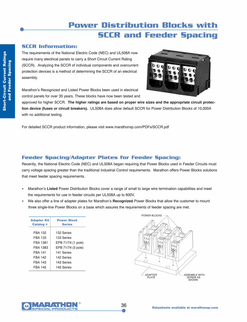
SCCR Information:The requirements of the National Electric Code (NEC) and UL508A now
require many electrical panels to carry a Short Circuit Current Rating
(SCCR). Analyzing the SCCR of individual components and overcurrent
protection devices is a method of determining the SCCR of an electrical
assembly.
Marathon’s Recognized and Listed Power Blocks been used in electrical
control panels for over 35 years. These blocks have now been tested and
approved for higher SCCR. The higher ratings are based on proper wire sizes and the appropriate circuit protec-
tion device (fuses or circuit breakers). UL508A does allow default SCCR for Power Distribution Blocks of 10,000A
with no additional testing.
For detailed SCCR product information, please visit www.marathonsp.com/PDFs/SCCR.pdf
Feeder Spacing/Adapter Plates for Feeder Spacing:Recently, the National Electric Code (NEC) and UL508A began requiring that Power Blocks used in Feeder Circuits must
carry voltage spacing greater than the traditional Industrial Control requirements. Marathon offers Power Blocks solutions
that meet feeder spacing requirements.
• Marathon’s Listed Power Distribution Blocks cover a range of small to large wire termination capabilities and meet
the requirements for use in feeder circuits per UL508A up to 600V.
• We also offer a line of adapter plates for Marathon’s Recognized Power Blocks that allow the customer to mount
three single-line Power Blocks on a base which assures the requirements of feeder spacing are met.
Adapter KitCatalog #
Power Block Series
FBA 132FBA 133FBA 1381FBA 1383FBA 141FBA 142FBA 143FBA 145
132 Series133 SeriesEPB 71/74 (1 pole)EPB 71/74 (3 pole)141 Series142 Series143 Series145 Series
POWER BLOCKS
ADAPTERPLATE
ASSEMBLE WITHSCREW AS
SHOWN
Datasheets available at marathonsp.com
37
UL Listed Power Distribution Blocks
UL Liste
d
Pow
er D
istributio
n B
locks
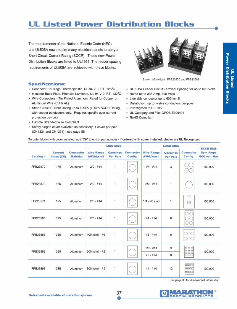
The requirements of the National Electric Code (NEC)
and UL508A now require many electrical panels to carry a
Short Circuit Current Rating (SCCR). These new Power
Distribution Blocks are listed to UL1953. The feeder spacing
requirements of UL508A are achieved with these blocks.
SCCR RMSSym Amps
600 volt MaxCatalog #
FPB23570
LINE SIDE
Wire RangeAWG/kcmil
FPB23574
FPB23580
FPB33553
FPB33595
FPB33588
FPB23572
2/0 - #14
2/0 - #14
2/0 - #14
400 kcmil - #6
600 kcmil - #2
600 kcmil - #2
2/0 - #14
#4 - #14
1/4 - 20 stud
#4 - #14
#2 - #14
#4 - #14
1/0 - #14
#2 - #14
2/0 - #14
Current Amps (CU)
175
175
175
335
335
335
175
See page 38 for dimensional information.
Specifications:• Connector Housings, Thermoplastic, UL 94 V-0, RTI 125oC • Insulator Base Plate, Phenolic Laminate, UL 94 V-0, RTI 130oC• Wire Connectors - Tin Plated Aluminum, Rated for Copper or
Aluminum Wire (CU & AL)• Short Circuit Current Rating up to 100kA (100kA SCCR Rating
with copper conductors only. Requires specific over-current protection device.)
• Flexible Stranded Wire Compliant• Safety hinged cover available as accessory, 1 cover per pole (CH1321 and CH1331) - see page 58
• UL 508A Feeder Circuit Terminal Spacing for up to 600 Volts• Rated up to 335 Amp, 600 Volts• Line side conductor up to 600 kcmil• Distribution, up to twelve conductors per pole• Investigated to UL 1953• UL Category and File: QPQS.E309401• RoHS Compliant
100,000
100,000
100,000
100,000
100,000
100,000
100,000
Connector Material
Aluminum
Aluminum
Aluminum
Aluminum
Aluminum
Aluminum
Aluminum
Connector Config.
Connector Config.
Wire RangeAWG/kcmil
Openings Per Pole
1
1
1
1
1
1
1
Openings Per Pole
4
1
6
6
12
1
3
6
LOAD SIDE
To order blocks with cover installed, add “CH” to end of part number - if ordered with cover installed, blocks are UL Recognized
Shown left to right: FPB23570 and FPB33588
Datasheets available at marathonsp.com
.389.5
4.75120.6
1.3834.9
3.2582.5
6.00152.4
Ø .22 [5.6] THRUCBØ .50 X .38 DP 4X [12.7 X 9.7 DP]
5.50139.7
3.96100.5
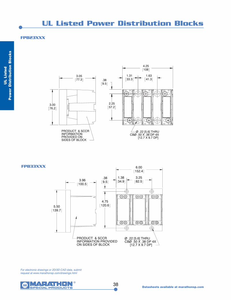
PRODUCT & SCCR INFORMATION PROVIDED ON SIDES OF BLOCK
4.25108
1.3133.3
1.6341.3.38
9.5
2.2557.2
Ø .22 [5.6] THRUCBØ .50 X .38 DP 4X
[12.7 X 9.7 DP]
3.0577.3
3.0076.2
PRODUCT & SCCR INFORMATIONPROVIDED ON SIDES OF BLOCK
38
UL Listed Power Distribution Blocks
UL
List
ed
P
ow
er
Dis
trib
uti
on B
lock
s
FPB23XXX
FPB33XXX
Datasheets available at marathonsp.com
For electronic drawings or 2D/3D CAD data, submit request at www.marathonsp.com/drawings.html
39
UL Listed Power Distribution Blocks
For electronic drawings or 2D/3D CAD data, submit request at www.marathonsp.com/drawings.html
Datasheets available at marathonsp.com
UL Liste
d
Pow
er D
istributio
n B
locks
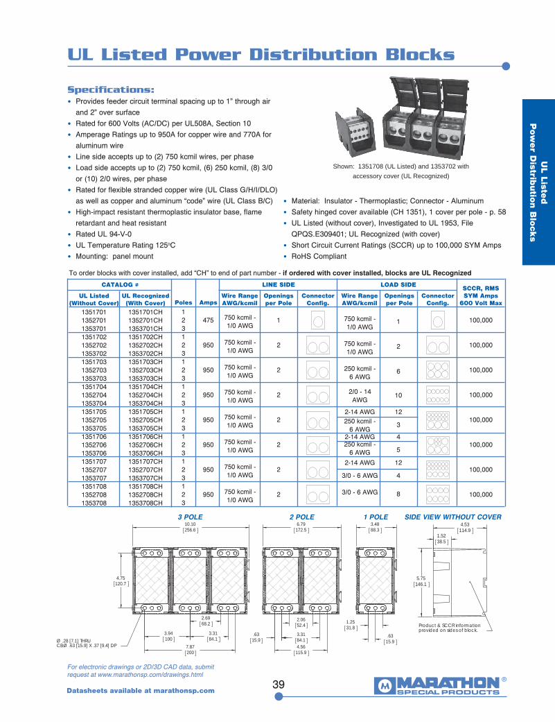
Specifications:• Provides feeder circuit terminal spacing up to 1” through air
and 2” over surface• Rated for 600 Volts (AC/DC) per UL508A, Section 10• Amperage Ratings up to 950A for copper wire and 770A for
aluminum wire• Line side accepts up to (2) 750 kcmil wires, per phase• Load side accepts up to (2) 750 kcmil, (6) 250 kcmil, (8) 3/0 or (10) 2/0 wires, per phase• Rated for flexible stranded copper wire (UL Class G/H/I/DLO) as well as copper and aluminum “code” wire (UL Class B/C)• High-impact resistant thermoplastic insulator base, flame retardant and heat resistant• Rated UL 94-V-0• UL Temperature Rating 125oC• Mounting: panel mount
Shown: 1351708 (UL Listed) and 1353702 with accessory cover (UL Recognized)
• Material: Insulator - Thermoplastic; Connector - Aluminum• Safety hinged cover available (CH 1351), 1 cover per pole - p. 58• UL Listed (without cover), Investigated to UL 1953, File QPQS.E309401; UL Recognized (with cover)• Short Circuit Current Ratings (SCCR) up to 100,000 SYM Amps• RoHS Compliant
135170113527011353701135170213527021353702135170313527031353703135170413527041353704135170513527051353705135170613527061353706135170713527071353707135170813527081353708
CATALOG #
UL Listed(Without Cover) Poles Amps
LINE SIDE
Wire Range AWG/kcmil
Openings per Pole
ConnectorConfig.
LOAD SIDE
Wire Range AWG/kcmil
Openings per Pole
ConnectorConfig.
SCCR, RMS SYM Amps
600 Volt Max123123123123123123123123
475
950
950
950
950
950
950
950
100,000
100,000
100,000
100,000
100,000
100,000
100,000
100,000
1
2
2
2
2
2
2
2
750 kcmil - 1/0 AWG
750 kcmil - 1/0 AWG
750 kcmil - 1/0 AWG
750 kcmil - 1/0 AWG
750 kcmil - 1/0 AWG
750 kcmil - 1/0 AWG
750 kcmil - 1/0 AWG
750 kcmil - 1/0 AWG
1
2
6
10
12
3
4
5
12
4
8
750 kcmil - 1/0 AWG
750 kcmil - 1/0 AWG
250 kcmil - 6 AWG
2/0 - 14 AWG
2-14 AWG250 kcmil -
6 AWG2-14 AWG250 kcmil -
6 AWG
2-14 AWG
3/0 - 6 AWG
3/0 - 6 AWG
4.75120.7
7.87200
3.94100
3.3184.1
2.6968.2
10.10256.6
Ø .28 [7.1] THRUCBØ .63 [15.9] X .37 [9.4] DP
1.5238.5
5.75146.1
4.53114.9
Product & SCCR informationprovided on sides of block.
4.56115.9
2.0652.4
3.3184.1
.6315.9
6.79172.5
1.2531.8
.6315.9
3.4888.3
4.75120.7
7.87200
3.94100
3.3184.1
2.6968.2
10.10256.6
Ø .28 [7.1] THRUCBØ .63 [15.9] X .37 [9.4] DP
1.5238.5
5.75146.1
4.53114.9
Product & SCCR informationprovided on sides of block.
4.56115.9
2.0652.4
3.3184.1
.6315.9
6.79172.5
1.2531.8
.6315.9
3.4888.3
SIDE VIEW WITHOUT COVER 3 POLE 2 POLE 1 POLE
To order blocks with cover installed, add “CH” to end of part number - if ordered with cover installed, blocks are UL Recognized
1351701CH1352701CH1353701CH1351702CH1352702CH1353702CH1351703CH1352703CH1353703CH1351704CH1352704CH1353704CH1351705CH1352705CH1353705CH1351706CH1352706CH1353706CH1351707CH1352707CH1353707CH1351708CH1352708CH1353708CH
UL Recognized (With Cover)
40
UL Listed Enclosed Power Distribution Blocks
UL
List
ed
Encl
ose
d
Pow
er
Dis
trib
uti
on B
lock
s
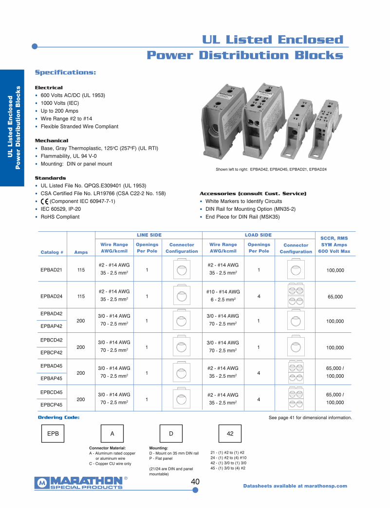
Specifications:
Electrical
• 600 Volts AC/DC (UL 1953) • 1000 Volts (IEC)• Up to 200 Amps• Wire Range #2 to #14• Flexible Stranded Wire Compliant
Mechanical
• Base, Gray Thermoplastic, 125oC (257oF) (UL RTI)• Flammability, UL 94 V-0• Mounting: DIN or panel mount
Standards
• UL Listed File No. QPQS.E309401 (UL 1953)• CSA Certified File No. LR19766 (CSA C22-2 No. 158)• (Component IEC 60947-7-1)• IEC 60529, IP-20• RoHS Compliant
Shown left to right: EPBAD42, EPBAD45, EPBAD21, EPBAD24
Datasheets available at marathonsp.com
EPB A D 42
Connector Material:A - Aluminum rated copper or aluminum wireC - Copper CU wire only
Mounting:D - Mount on 35 mm DIN railP - Flat panel
(21/24 are DIN and panel mountable)
21 - (1) #2 to (1) #224 - (1) #2 to (4) #1042 - (1) 3/0 to (1) 3/045 - (1) 3/0 to (4) #2
Ordering Code:
EPBAD21
EPBAD24
100,000
65,000
115
115
#2 - #14 AWG
35 - 2.5 mm2 1
1
1
4#2 - #14 AWG
35 - 2.5 mm2
#2 - #14 AWG
35 - 2.5 mm2
#10 - #14 AWG
6 - 2.5 mm2
Catalog #
SCCR, RMS SYM Amps
600 Volt MaxAmps
Connector Configuration
Wire RangeAWG/kcmil
Wire RangeAWG/kcmil
Connector Configuration
Openings Per Pole
Openings Per Pole
LINE SIDE LOAD SIDE
EPBAD42
EPBCD42
100,000
100,000
200
200
3/0 - #14 AWG
70 - 2.5 mm2 1
1
1
13/0 - #14 AWG
70 - 2.5 mm2
3/0 - #14 AWG
70 - 2.5 mm2
3/0 - #14 AWG
70 - 2.5 mm2
EPBAD45
EPBCD45
65,000 /
100,000
65,000 /
100,000
200
200
3/0 - #14 AWG
70 - 2.5 mm2 1
1
4
43/0 - #14 AWG
70 - 2.5 mm2
#2 - #14 AWG
35 - 2.5 mm2
#2 - #14 AWG
35 - 2.5 mm2
EPBAP42
EPBCP42
EPBAP45
EPBCP45
Accessories (consult Cust. Service)
• White Markers to Identify Circuits• DIN Rail for Mounting Option (MN35-2)• End Piece for DIN Rail (MSK35)
See page 41 for dimensional information.
41
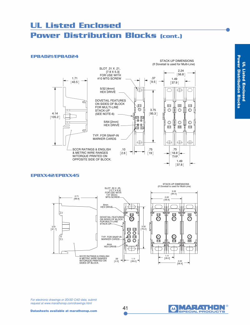
UL Listed Enclosed Power Distribution Blocks (cont.)
UL Liste
d E
nclo
sed
P
ow
er D
istributio
n B
locks
STACK-UP DIMENSIONS(If Dovetail is used for Multi-Line)
.379.5
3.7595.3
.102.6
.7519
5/32 [4mm]HEX DRIVE
5/64 [2mm]HEX DRIVE
SLOT .31 X .21, [7.9 X 5.3]FOR USE WITH
#10 MTG SCREW
DOVETAIL FEATURESON SIDES OF BLOCKFOR MULTI-LINE STACK-UP(SEE NOTE-6)
TYP. FOR SNAP-INMARKER CARDS
4.14105.2
1.7143.5
SCCR RATINGS & ENGLISH& METRIC WIRE RANGES W/TORQUE PRINTED ON OPPOSITE SIDE OF BLOCK.
.75
TYP.18.9
1.4937.8
1.4937.9
2.2456.8
Datasheets available at marathonsp.com
3.0076.2
.092.3
1.1128.2
1.1128.2
2.2256.4
2.2256.4
3.3384.5
STACK-UP DIMENSIONS(If Dovetail is used for Mulit-Line)
4mmHEX DRIVE
6mmHEX DRIVE
SLOT .50 X .25, [12.7 X 6.4]FOR USE WITH
1/4" (6mm) MTG SCREW
DOVETAIL FEATURESON SIDES OF BLOCKFOR MULTI-LINE STACK-UP
TYP. FOR SNAP-INMARKER CARDS
3.6191.7
2.7168.9
SCCR RATINGS & ENGLISH& METRIC WIRE RANGES W/TORQUE PRINTED ON SIDES OF BLOCK.
For electronic drawings or 2D/3D CAD data, submit request at www.marathonsp.com/drawings.html
EPBAD21/EPBAD24
EPBXX42/EPBXX45
42
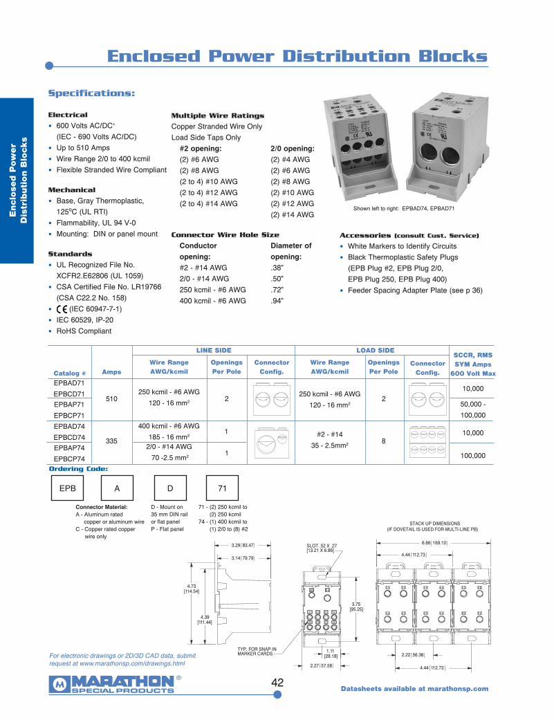
Enclosed Power Distribution Blocks
Encl
ose
d P
ow
er
Dis
trib
uti
on B
lock
s
4.39[111.44]
4.73[114.54]
3.29 83.47
3.14 79.79
2.22 56.36
4.44 112.73
4.44 112.73
6.66 169.10
STACK UP DIMENSIONS(IF DOVETAIL IS USED FOR MULTI-LINE PB)
3.75[95.25]
1.11[28.18]
2.27 57.58
SLOT .52 X .27[13.21 X 6.86]
TYP. FOR SNAP-INMARKER CARDS
Datasheets available at marathonsp.com
Specifications:
Electrical
• 600 Volts AC/DC+ (IEC - 690 Volts AC/DC)• Up to 510 Amps• Wire Range 2/0 to 400 kcmil• Flexible Stranded Wire Compliant
Mechanical
• Base, Gray Thermoplastic, 125oC (UL RTI)• Flammability, UL 94 V-0• Mounting: DIN or panel mount
Standards
• UL Recognized File No. XCFR2.E62806 (UL 1059)• CSA Certified File No. LR19766 (CSA C22.2 No. 158)• (IEC 60947-7-1)• IEC 60529, IP-20• RoHS Compliant
Catalog #
SCCR, RMS SYM Amps
600 Volt MaxAmpsConnector
Config.Wire RangeAWG/kcmil
Wire RangeAWG/kcmil
Connector Config.
Openings Per Pole
Openings Per Pole
EPB A D 71
Connector Material:A - Aluminum rated copper or aluminum wireC - Copper rated copper wire only
D - Mount on 35 mm DIN rail or flat panelP - Flat panel
71 - (2) 250 kcmil to (2) 250 kcmil74 - (1) 400 kcmil to (1) 2/0 to (8) #2
Ordering Code:
Multiple Wire Ratings
Copper Stranded Wire OnlyLoad Side Taps Only #2 opening: 2/0 opening: (2) #6 AWG (2) #4 AWG (2) #8 AWG (2) #6 AWG (2 to 4) #10 AWG (2) #8 AWG (2 to 4) #12 AWG (2) #10 AWG (2 to 4) #14 AWG (2) #12 AWG (2) #14 AWG
Connector Wire Hole Size
Conductor Diameter of opening: opening: #2 - #14 AWG .38” 2/0 - #14 AWG .50” 250 kcmil - #6 AWG .72” 400 kcmil - #6 AWG .94”
EPBAD71
EPBCD7110,000
510 2 2250 kcmil - #6 AWG
120 - 16 mm2
250 kcmil - #6 AWG
120 - 16 mm2EPBAP71
EPBCP71
50,000 -
100,000
EPBAD74
EPBCD7410,000
335 8
400 kcmil - #6 AWG
185 - 16 mm2 #2 - #14
35 - 2.5mm2EPBAP74
EPBCP74 100,0002/0 - #14 AWG
70 -2.5 mm2
1
1
LINE SIDE LOAD SIDE
Accessories (consult Cust. Service)
• White Markers to Identify Circuits• Black Thermoplastic Safety Plugs (EPB Plug #2, EPB Plug 2/0, EPB Plug 250, EPB Plug 400)• Feeder Spacing Adapter Plate (see p 36)
For electronic drawings or 2D/3D CAD data, submit request at www.marathonsp.com/drawings.html
Shown left to right: EPBAD74, EPBAD71

43
Power Terminal Blocks
Pow
er B
locks
General Information:Barrier Style Power Terminal Blocks are available in eight sizes. They are identified by the first three digits of the catalog number. The 140, 142, 143, 144 and 145 series are manufactured with general purpose phenolic rated at 150oC. The 141, 132 and 133 series are manufactured with high impact thermoplastic rated at 125oC.
Conductor Opening Diameter of Opening
* Enclosed blocks have larger openings (see page 42)
Ratings and Standards:The voltage ratings of terminal blocks are based upon the minimum spacing between electrically conductive parts line to line through air and over surface and line to ground through air and over surface.
Class A Service equipment including deadfront switchboards, panel boards, service entrance devices.
Class B Commercial appliances including business equipment, electronic data processing equipment and the like.
Class C General industrial and machine tool controls which can be further defined as equipment falling under UL 508. Ratings based on UL 1059 may be higher in some cases depending on application.
Applications:Designed for use with solar, wind, alternate energy, transportation, heating, air conditioning and refrigeration, elevator systems, material handling equipment, control panels, motor control, switchgear and any area where power needs to be distributed to more than one load.
Metric6
2535507095
120185
-240300
--
Voltage Thru Air Over Surface
51-150 .500 .750 Class A 151-300 .750 1.250 301-600 1.000 2.000 51-150 .063 .063 Class B 151-300 .094 .094 301-600 .375 .500 51-150 .125 .250 Class C 151-300 .250 .375 301-600 .375 .500
Spacing Requirements (in inches):
Metric4.06.47.9
10.311.113.516.018.2
-22.223.8
--
Inch.158”.250”.312”*.406”.438”*.532”.630”*.718”.769”*.875”.938”
1.125”1.250”
English#10 AWG#4 AWG#2 AWG
1/02/03/0
250 kcmil350 kcmil400 kcmil500 kcmil600 kcmil750 kcmil
1000 kcmil
Connector Wire Hole Size:
Datasheets available at marathonsp.com
44
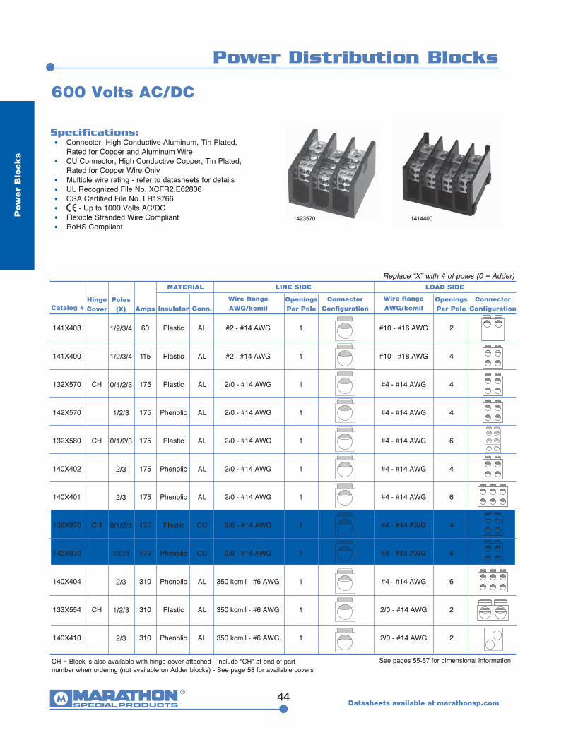
Power Distribution Blocks
Pow
er
Blo
cks
Specifications: • Connector, High Conductive Aluminum, Tin Plated,
Rated for Copper and Aluminum Wire • CU Connector, High Conductive Copper, Tin Plated, Rated for Copper Wire Only • Multiple wire rating - refer to datasheets for details • UL Recognized File No. XCFR2.E62806 • CSA Certified File No. LR19766 • - Up to 1000 Volts AC/DC • Flexible Stranded Wire Compliant • RoHS Compliant
600 Volts AC/DC
CH = Block is also available with hinge cover attached - include “CH” at end of part number when ordering (not available on Adder blocks) - See page 58 for available covers
Catalog #Poles
(X) Amps
MATERIAL
ConnectorConfiguration
Wire RangeAWG/kcmil
Wire RangeAWG/kcmil
Openings Per Pole
Openings Per Pole
141X403
141X400
132X570
142X570
132X580
140X402
140X401
132X970
142X970
140X404
133X554
140X410
ConnectorConfiguration
Replace “X” with # of poles (0 = Adder)
60
115
175
175
175
175
175
175
175
310
310
310
Plastic
Plastic
Plastic
Phenolic
Plastic
Phenolic
Phenolic
Plastic
Phenolic
Phenolic
Plastic
Phenolic
#2 - #14 AWG
#2 - #14 AWG
2/0 - #14 AWG
2/0 - #14 AWG
2/0 - #14 AWG
2/0 - #14 AWG
2/0 - #14 AWG
2/0 - #14 AWG
2/0 - #14 AWG
350 kcmil - #6 AWG
350 kcmil - #6 AWG
350 kcmil - #6 AWG
1
1
1
1
1
1
1
1
1
1
1
1
#10 - #16 AWG
#10 - #18 AWG
#4 - #14 AWG
#4 - #14 AWG
#4 - #14 AWG
#4 - #14 AWG
#4 - #14 AWG
#4 - #14 AWG
#4 - #14 AWG
#4 - #14 AWG
2/0 - #14 AWG
2/0 - #14 AWG
2
4
4
4
6
4
6
4
4
6
2
2
See pages 55-57 for dimensional information
1423570 1414400
HingeCover
CH
CH
CH
CH
Conn.Insulator
1/2/3/4
1/2/3/4
0/1/2/3
1/2/3
0/1/2/3
2/3
2/3
0/1/2/3
1/2/3
2/3
1/2/3
2/3
LINE SIDE LOAD SIDE
Datasheets available at marathonsp.com
AL
AL
AL
AL
AL
AL
AL
CU
CU
AL
AL
AL

45
Power Distribution Blocks
Datasheets available at marathonsp.com
Pow
er B
locks
600 Volts AC/DC
1443560 1433553
Catalog #Poles
(X) Amps
MATERIAL
ConnectorConfiguration
Wire RangeAWG/kcmil
Wire RangeAWG/kcmil
Openings Per Pole
Openings Per Pole
ConnectorConfiguration
Replace “X” with # of poles
HingeCover
CH
CH
CH
Conn.Insulator
143X554
144X401
143X552
143X553
144X560
133X552
143X555
133X555
143X955
133X955
143X953
310
335
335
335
335
335
350
350
350
350
380
Phenolic
Phenolic
Phenolic
Phenolic
Phenolic
Plastic
Phenolic
Plastic
Phenolic
Plastic
Phenolic
1
1
1
1
1
1
2
2
2
2
1
2
6
4
6
8
4
6
6
6
6
6
1/2/3
1/2/3
1/2/3
1/2/3
1/2/3
1/2/3
1/2/3
1/2/3
1/2/3
1/2/3
1/2/3
AL
AL
AL
AL
AL
AL
AL
AL
CU
CU
CU
LINE SIDE LOAD SIDE
Specifications: • Connector, High Conductive Aluminum, Tin Plated,
Rated for Copper and Aluminum Wire • CU Connector, High Conductive Copper, Tin Plated, Rated for Copper Wire Only • Multiple wire rating - refer to datasheets for details • UL Recognized File No. XCFR2.E62806 • CSA Certified File No. LR19766 • - Up to 1000 Volts AC/DC • Flexible Stranded Wire Compliant • RoHS Compliant
CH = Block is also available with hinge cover attached - include “CH” at end of part number when ordering (not available on Adder blocks) - See page 58 for available covers
See pages 55-57 for dimensional information
350 kcmil - #6 AWG
400 kcmil - #6 AWG
400 kcmil - #6 AWG
400 kcmil - #6 AWG
400 kcmil - #6 AWG
400 kcmil - #6 AWG
2/0 - #14 AWG
2/0 - #14 AWG
2/0 - #14 AWG
2/0 - #14 AWG
500 kcmil - #4 AWG
2/0 - #14 AWG
#2 - #14 AWG
#2 - #14 AWG
#2 - #14 AWG
#2 - #14 AWG
#2 - #14 AWG
#4 - #14 AWG
#4 - #14 AWG
#4 - #14 AWG
#4 - #14 AWG
#2 - #14 AWG
CU
AL
AL
AL
AL
AL
AL
AL
AL
AL
AL
AL
46
Pow
er
Blo
cks
Power Distribution Blocks (cont.)
600 Volts AC/DC
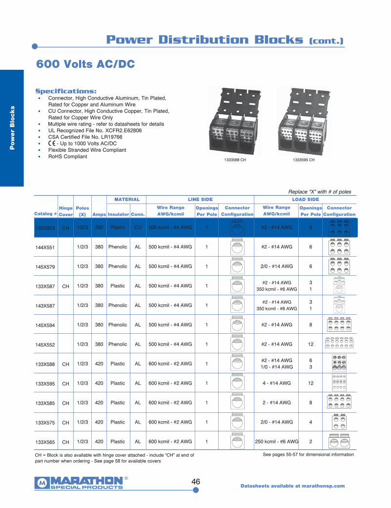
CH = Block is also available with hinge cover attached - include “CH” at end of part number when ordering - See page 58 for available covers
Catalog #Poles
(X) Amps
MATERIAL
ConnectorConfiguration
Wire RangeAWG/kcmil
Wire RangeAWG/kcmil
Openings Per Pole
Openings Per Pole
133X953
144X551
145X579
133X587
143X587
145X594
145X552
133X588
133X595
133X585
133X575
133X565
ConnectorConfiguration
Replace “X” with # of poles
380
380
380
380
380
380
380
420
420
420
420
420
Plastic
Phenolic
Phenolic
Plastic
Phenolic
Phenolic
Phenolic
Plastic
Plastic
Plastic
Plastic
Plastic
500 kcmil - #4 AWG
500 kcmil - #4 AWG
500 kcmil - #4 AWG
500 kcmil - #4 AWG
500 kcmil - #4 AWG
500 kcmil - #4 AWG
500 kcmil - #4 AWG
600 kcmil - #2 AWG
600 kcmil - #2 AWG
600 kcmil - #2 AWG
600 kcmil - #2 AWG
600 kcmil - #2 AWG
1
1
1
1
1
1
1
1
1
1
1
1
#2 - #14 AWG
#2 - #14 AWG
2/0 - #14 AWG
#2 - #14 AWG350 kcmil - #6 AWG
#2 - #14 AWG350 kcmil - #6 AWG
#2 - #14 AWG
#2 - #14 AWG
#2 - #14 AWG1/0 - #14 AWG
4 - #14 AWG
2 - #14 AWG
2/0 - #14 AWG
250 kcmil - #6 AWG
6
6
6
31
31
8
12
63
12
8
4
2
See pages 55-57 for dimensional information
HingeCover
CH
CH
CH
CH
CH
CH
CH
Conn.Insulator
1/2/3
1/2/3
1/2/3
1/2/3
1/2/3
1/2/3
1/2/3
1/2/3
1/2/3
1/2/3
1/2/3
1/2/3
LINE SIDE LOAD SIDE
1333588 CH 1333595 CH
Specifications: • Connector, High Conductive Aluminum, Tin Plated,
Rated for Copper and Aluminum Wire • CU Connector, High Conductive Copper, Tin Plated, Rated for Copper Wire Only • Multiple wire rating - refer to datasheets for details • UL Recognized File No. XCFR2.E62806 • CSA Certified File No. LR19766 • - Up to 1000 Volts AC/DC • Flexible Stranded Wire Compliant • RoHS Compliant
Datasheets available at marathonsp.com
47
Pow
er B
locks
Power Distribution Blocks (cont.)
Datasheets available at marathonsp.com
*Special one-pole block. Apply Power Block Dimensions for 145 Series block on page 57 (3 pole).
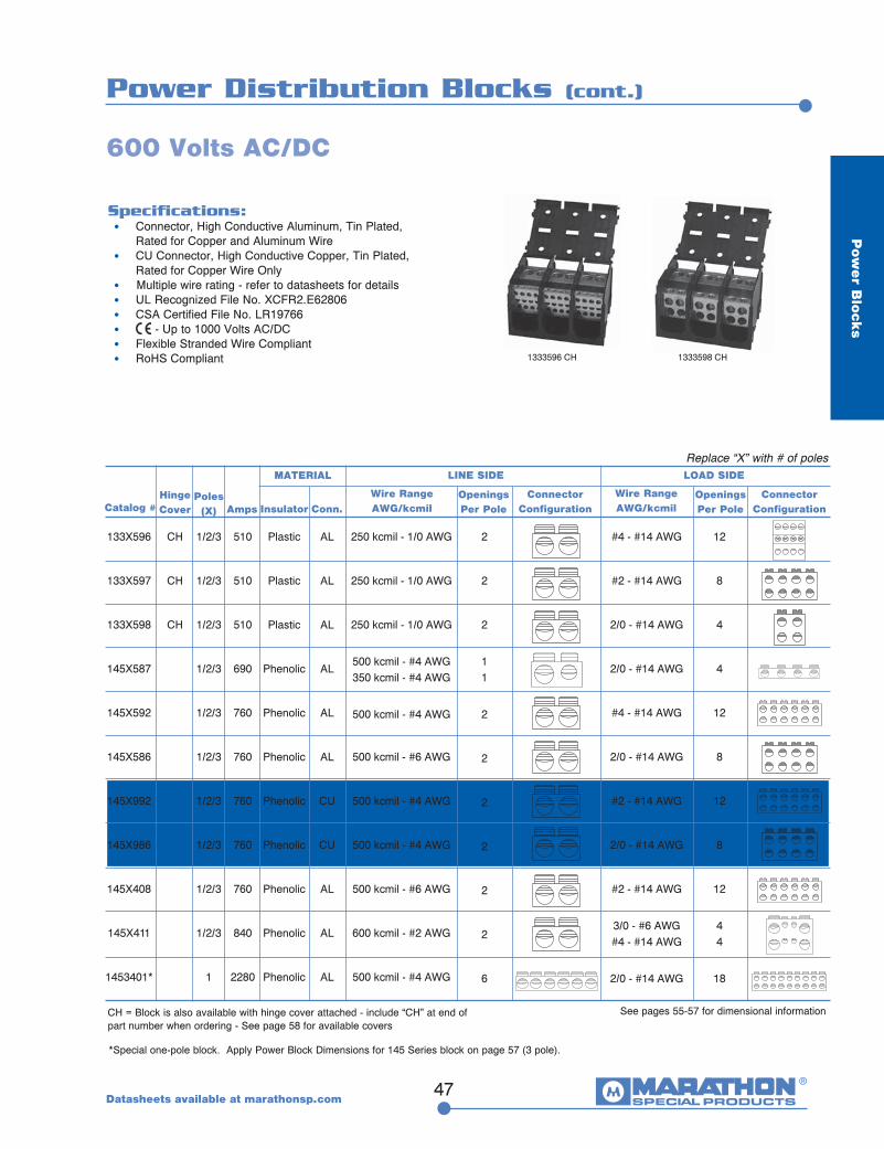
133X596
133X597
133X598
145X587
145X592
145X586
145X992
145X986
145X408
145X411
1453401*
CH
CH
CH
1/2/3
1/2/3
1/2/3
1/2/3
1/2/3
1/2/3
1/2/3
1/2/3
1/2/3
1/2/3
1
510
510
510
690
760
760
760
760
760
840
2280
Plastic
Plastic
Plastic
Phenolic
Phenolic
Phenolic
Phenolic
Phenolic
Phenolic
Phenolic
Phenolic
250 kcmil - 1/0 AWG
250 kcmil - 1/0 AWG
250 kcmil - 1/0 AWG
500 kcmil - #4 AWG350 kcmil - #4 AWG
500 kcmil - #4 AWG
500 kcmil - #6 AWG
500 kcmil - #4 AWG
500 kcmil - #4 AWG
500 kcmil - #6 AWG
600 kcmil - #2 AWG
500 kcmil - #4 AWG
#4 - #14 AWG
#2 - #14 AWG
2/0 - #14 AWG
2/0 - #14 AWG
#4 - #14 AWG
2/0 - #14 AWG
#2 - #14 AWG
2/0 - #14 AWG
#2 - #14 AWG
3/0 - #6 AWG#4 - #14 AWG
2/0 - #14 AWG
2
2
2
11
2
2
2
2
2
2
6
12
8
4
4
12
8
12
8
12
44
18
600 Volts AC/DC
Specifications: • Connector, High Conductive Aluminum, Tin Plated,
Rated for Copper and Aluminum Wire • CU Connector, High Conductive Copper, Tin Plated, Rated for Copper Wire Only • Multiple wire rating - refer to datasheets for details • UL Recognized File No. XCFR2.E62806 • CSA Certified File No. LR19766 • - Up to 1000 Volts AC/DC • Flexible Stranded Wire Compliant • RoHS Compliant
CH = Block is also available with hinge cover attached - include “CH” at end of part number when ordering - See page 58 for available covers
Catalog #Poles
(X) Amps
MATERIAL
ConnectorConfiguration
Wire RangeAWG/kcmil
Wire RangeAWG/kcmil
Openings Per Pole
Openings Per Pole
ConnectorConfiguration
Replace “X” with # of poles
See pages 55-57 for dimensional information
HingeCover Conn.Insulator
LINE SIDE LOAD SIDE
1333596 CH 1333598 CH
AL
AL
AL
AL
AL
AL
CU
CU
AL
AL
AL

AL
AL
AL
AL
CU
CU
CU
CU
AL
AL
AL
48
Power Splicer Blocks
Pow
er
Blo
cks
Specifications: • Connector, High Conductive Aluminum, Tin Plated, Rated for
Copper and Aluminum Wire • CU Connector, High Conductive Copper, Tin Plated, Rated for Copper Wire Only • Multiple wire rating - refer to datasheets for details • UL Recognized File No. XCFR2.E62806 • CSA Certified File No. LR19766 • - Up to 1000 Volts AC/DC • Flexible Stranded Wire Compliant • RoHS Compliant
600 Volts AC/DC
1323972 CH 1323572 CH
CH = Block is also available with hinge cover attached - include “CH” at end of part number when ordering (not available on Adder blocks) - See page 58 for available covers
Catalog #Poles
(X) Amps
MATERIAL
ConnectorConfiguration
Wire RangeAWG/kcmil
Wire RangeAWG/kcmil
Openings Per Pole
Openings Per Pole
141X300
142X552
132X572
142X572
132X972
142X121
143X124
140X801
143X123
140X303
143X126
ConnectorConfiguration
Replace “X” with # of poles (0 = Adder)
115
115
175
175
175
175
255
255
255
310
310
Plastic
Phenolic
Plastic
Phenolic
Plastic
Phenolic
Phenolic
Phenolic
Phenolic
Phenolic
Phenolic
#2 - #14 AWG
#2 - #14 AWG
2/0 - #14 AWG
2/0 - #14 AWG
2/0 - #14 AWG
1/0 - #14 AWG
250 kcmil - #6 AWG
250 kcmil - #6 AWG
250 kcmil - #6 AWG
350 kcmil - #6 AWG
350 kcmil - #6 AWG
1
1
1
1
1
1
1
1
1
1
1
#2 - #14 AWG
#2 - #14 AWG
2/0 - #14 AWG
2/0 - #14 AWG
2/0 - #14 AWG
1/0 - #14 AWG
250 kcmil - #6 AWG
250 kcmil - #6 AWG
250 kcmil - #6 AWG
350 kcmil - #6 AWG
350 kcmil - #6 AWG
1
1
1
1
1
1
1
1
1
1
1
See pages 55-57 for dimensional information
HingeCover
CH
CH
Conn.Insulator
1/2/3/4
1/2/3
0/1/2/3
1/2/3
0/1/2/3
1/2/3
1/2/3
2/3
1/2/3
2/3
1/2/3
LINE SIDE LOAD SIDE
Datasheets available at marathonsp.com
49
Power Splicer Blocks (cont.)
Pow
er B
locks
Datasheets available at marathonsp.com
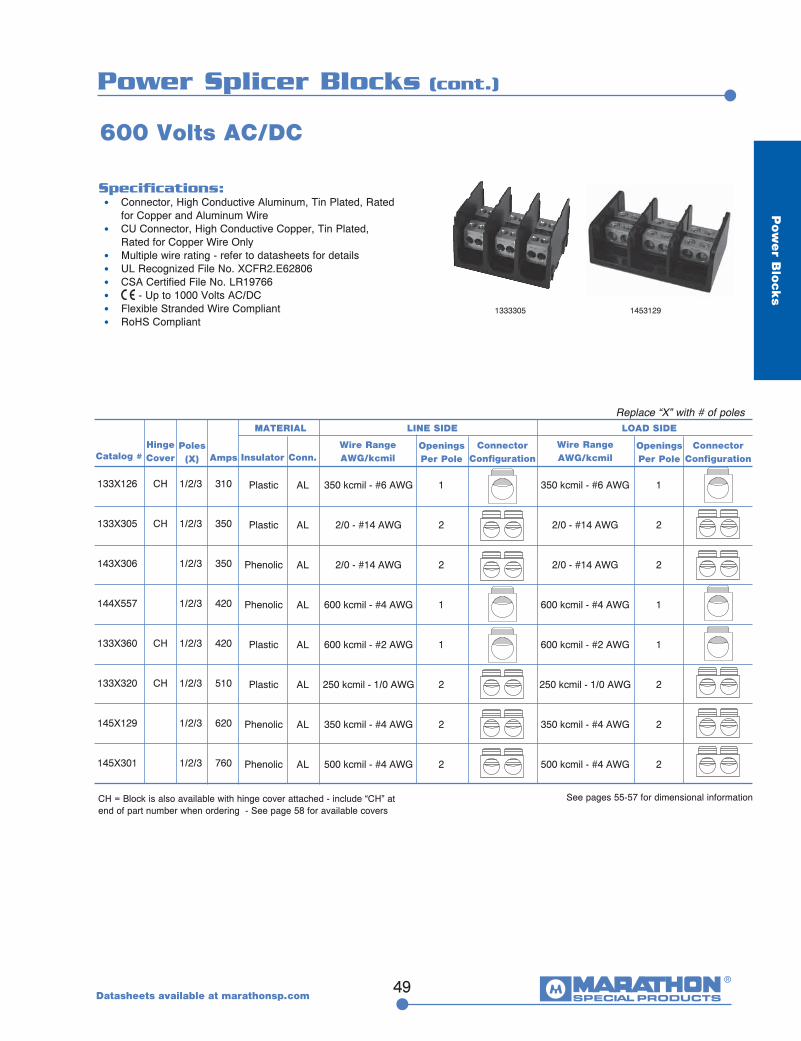
133X126
133X305
143X306
144X557
133X360
133X320
145X129
145X301
1/2/3
1/2/3
1/2/3
1/2/3
1/2/3
1/2/3
1/2/3
1/2/3
310
350
350
420
420
510
620
760
Plastic
Plastic
Phenolic
Phenolic
Plastic
Plastic
Phenolic
Phenolic
350 kcmil - #6 AWG
2/0 - #14 AWG
2/0 - #14 AWG
600 kcmil - #4 AWG
600 kcmil - #2 AWG
250 kcmil - 1/0 AWG
350 kcmil - #4 AWG
500 kcmil - #4 AWG
1
2
2
1
1
2
2
2
350 kcmil - #6 AWG
2/0 - #14 AWG
2/0 - #14 AWG
600 kcmil - #4 AWG
600 kcmil - #2 AWG
250 kcmil - 1/0 AWG
350 kcmil - #4 AWG
500 kcmil - #4 AWG
1
2
2
1
1
2
2
2
CH
CH
CH
CH
AL
AL
AL
AL
AL
AL
AL
AL
CH = Block is also available with hinge cover attached - include “CH” at end of part number when ordering - See page 58 for available covers
Catalog #Poles
(X) Amps
MATERIAL
ConnectorConfiguration
Wire RangeAWG/kcmil
Wire RangeAWG/kcmil
Openings Per Pole
Openings Per Pole
ConnectorConfiguration
Replace “X” with # of poles
See pages 55-57 for dimensional information
HingeCover Conn.Insulator
LINE SIDE LOAD SIDE
Specifications: • Connector, High Conductive Aluminum, Tin Plated, Rated for Copper and Aluminum Wire • CU Connector, High Conductive Copper, Tin Plated, Rated for Copper Wire Only • Multiple wire rating - refer to datasheets for details • UL Recognized File No. XCFR2.E62806 • CSA Certified File No. LR19766 • - Up to 1000 Volts AC/DC • Flexible Stranded Wire Compliant • RoHS Compliant
600 Volts AC/DC
1333305 1453129

50
Power Stud Blocks
Datasheets available at marathonsp.com
Pow
er
Blo
cks
Specifications: • Connector, High Conductive Copper, Tin Plated • Stud, Brass, Tin Plated, Metric (M) Studs, Steel • Rated for multiple wire lugs, where applicable • Suitable for Compression Wire Lugs • Multiple wire rating - refer to datasheets for details • UL Recognized File No. XCFR2.E62806 • CSA Certified File No. LR19766 • - Up to 1000 Volts AC/DC • Flexible Stranded Wire Compliant • RoHS Compliant
600 Volts AC/DC
CH = Block is also available with hinge cover attached - include “CH” at end of part number when ordering (not available on Adder blocks) - See page 58 for available covers
Replace “X” with # of poles (0 = Adder)
See pages 55-57 for dimensional information
1423122 1423123
132X122
132X422
142X123
142X122
143X563
143X561
144X553
144X122
133X564
133X563
145X573
145X583
0/1/2/3
0/1/2/3
1/2/3
1/2/3
1/2/3
1/2/3
1/2/3
1/2/3
1/2/3
1/2/3
1/2/3
1/2/3
200
200
200
200
230
230
230
260
310
310
360
360
Plastic
Plastic
Phenolic
Phenolic
Phenolic
Phenolic
Phenolic
Phenolic
Plastic
Plastic
Phenolic
Phenolic
1/4-20 x 9/16
M6 x 15
1/4-20 Screw
1/4-20 x 9/16
3/8-16 x 1 3/16
3/8-16 x 1 3/16
3/8-16 x 1 7/16
3/8-16 x 1 7/16
M10 X 30
3/8-16 x 1 3/16
3/8-16 x 1 7/16
3/8-16 x 1 7/16
1
1
1
1
1
1
1
1
1
1
1
1
1/4-20 x 9/16
M6 x 15
1/4-20 Screw
1/4-20 x 9/16
3/8-16 x 1 3/16
1/4-20 x 1 3/16
3/8-16 x 1 7/16
1/4-20 x 1 9/16
M10 X 30
3/8-16 x 1 3/16
3/8-16 x 1 7/16
1/4-20 X 1 7/16
1
1
1
1
1
1
1
2
1
1
2
2
CH
CH
CH
CH
CU
CU
CU
CU
CU
CU
CU
CU
CU
CU
CU
CU
Catalog #Poles
(X) Amps
MATERIAL
ConnectorConfiguration
Wire RangeAWG/kcmil
Wire RangeAWG/kcmil
Openings Per Pole
Openings Per Pole
ConnectorConfiguration
HingeCover Conn.Insulator
LINE SIDE LOAD SIDE
1.125
1.122
0.75

Power Stud Blocks (cont.)
51
Pow
er B
locks
Specifications: • Connector, High Conductive Copper, Tin Plated • Stud, Brass, Tin Plated, Metric (M) Studs, Steel • Rated for multiple wire lugs, where applicable • Suitable for Compression Wire Lugs • Multiple wire rating - refer to datasheets for details • UL Recognized File No. XCFR2.E62806 • CSA Certified File No. LR19766 • - Up to 1000 Volts AC/DC • Flexible Stranded Wire Compliant • RoHS Compliant
600 Volts AC/DC
Replace “X” with # of poles (0 = Adder)
See pages 55-57 for dimensional informationSee page 58 for available covers
1453606 1443614
145X606
133X611
145X613
144X614
1/2/3
1/2/3
1/2/3
1/2/3
410
410
475
840
Phenolic
Plastic
Phenolic
Phenolic
1/2-13 x 1 7/16
1/2-13 x 1.38
3/8-10 x 1 7/16
3/8-16 x 1
1
1
2
1
1/2-13 x 1 7/16
1/2-13 x 1.38
3/8-10 x 1 7/16
3/8-16 x 1
1
1
1
1
CU
CU
CU
CU
Catalog #Poles
(X) Amps
MATERIAL
ConnectorConfiguration
Wire RangeAWG/kcmil
Wire RangeAWG/kcmil
Openings Per Pole
Openings Per Pole
ConnectorConfiguration
HingeCover Conn.Insulator
LINE SIDE LOAD SIDE
Datasheets available at marathonsp.com
CH
1.375
52
Pow
er
Blo
cks
Miscellaneous Power Splicer Blocks
Datasheets available at marathonsp.com
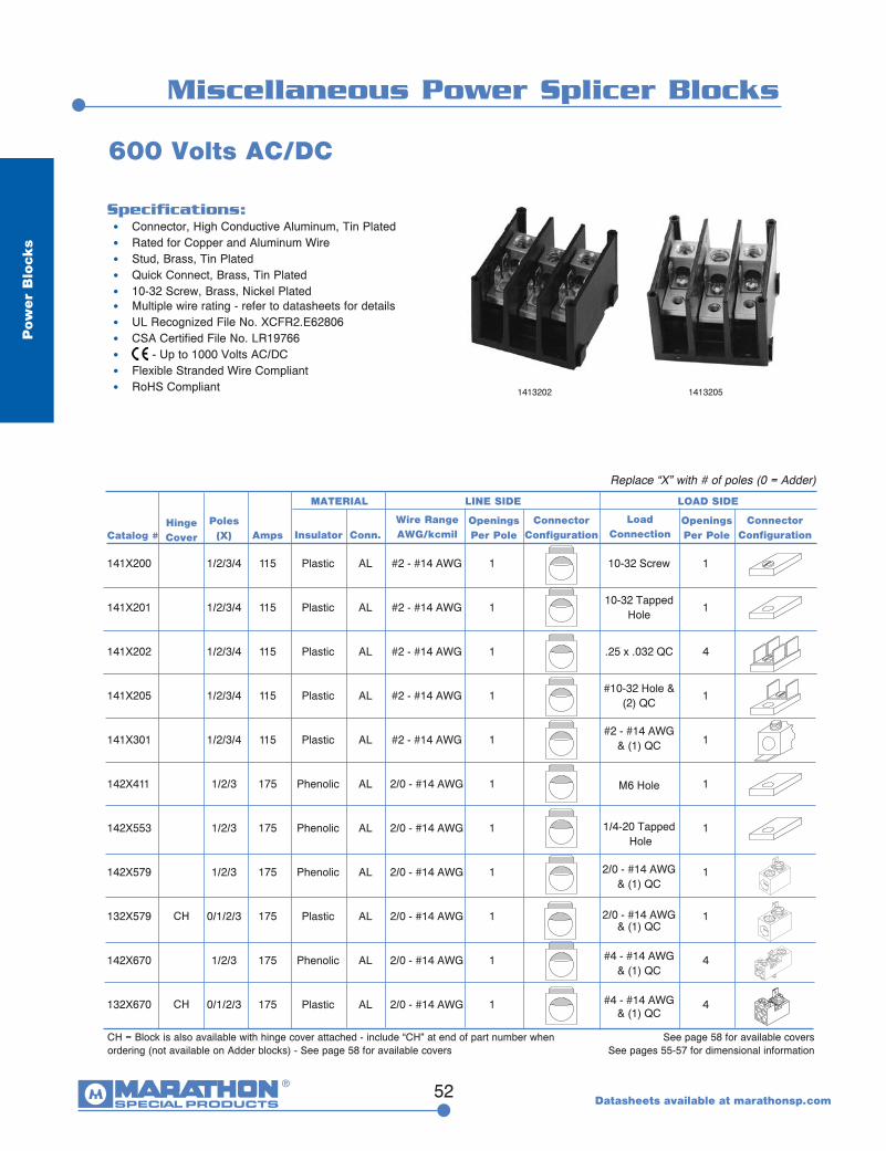
Specifications: • Connector, High Conductive Aluminum, Tin Plated • Rated for Copper and Aluminum Wire • Stud, Brass, Tin Plated • Quick Connect, Brass, Tin Plated • 10-32 Screw, Brass, Nickel Plated • Multiple wire rating - refer to datasheets for details • UL Recognized File No. XCFR2.E62806 • CSA Certified File No. LR19766 • - Up to 1000 Volts AC/DC • Flexible Stranded Wire Compliant • RoHS Compliant
600 Volts AC/DC
See page 58 for available coversSee pages 55-57 for dimensional information
1413202 1413205
141X200
141X201
141X202
141X205
141X301
142X411
142X553
142X579
132X579
142X670
132X670
1/2/3/4
1/2/3/4
1/2/3/4
1/2/3/4
1/2/3/4
1/2/3
1/2/3
1/2/3
0/1/2/3
1/2/3
0/1/2/3
115
115
115
115
115
175
175
175
175
175
175
Plastic
Plastic
Plastic
Plastic
Plastic
Phenolic
Phenolic
Phenolic
Plastic
Phenolic
Plastic
#2 - #14 AWG
#2 - #14 AWG
#2 - #14 AWG
#2 - #14 AWG
#2 - #14 AWG
2/0 - #14 AWG
2/0 - #14 AWG
2/0 - #14 AWG
2/0 - #14 AWG
2/0 - #14 AWG
2/0 - #14 AWG
10-32 Screw
10-32 Tapped Hole
.25 x .032 QC
#10-32 Hole & (2) QC
#2 - #14 AWG & (1) QC
M6 Hole
1/4-20 Tapped Hole
2/0 - #14 AWG & (1) QC
2/0 - #14 AWG & (1) QC
#4 - #14 AWG & (1) QC
#4 - #14 AWG & (1) QC
1
1
4
1
1
1
1
1
1
4
4
AL
AL
AL
AL
AL
AL
AL
AL
AL
AL
AL
Catalog #Poles
(X) Amps
MATERIAL
ConnectorConfiguration
Wire RangeAWG/kcmil
LoadConnection
Openings Per Pole
Openings Per Pole
ConnectorConfigurationConn.Insulator
1
1
1
1
1
1
1
1
1
1
1
LINE SIDE LOAD SIDE
Replace “X” with # of poles (0 = Adder)
CH = Block is also available with hinge cover attached - include “CH” at end of part number when ordering (not available on Adder blocks) - See page 58 for available covers
HingeCover
CH
CH

53
Pow
er B
locks
Specifications: • Connector, High Conductive Aluminum, Tin Plated, Rated for Copper and Aluminum Wire • Stud, Brass, Tin Plated, Metric (M) Studs, Steel - intended for wires terminated with crimp lugs • Multiple wire rating - refer to datasheets for details • UL Recognized File No. XCFR2.E62806 • CSA Certified File No. LR19766 • - Up to 1000 Volts AC/DC(does not apply to 133X559, 133X558, and 143X559) • Flexible Stranded Wire Compliant • RoHS Compliant
600 Volts AC/DC
CH = Block is also available with hinge cover attached - include “CH” at end of part number when ordering (not available on Adder blocks) - See page 58 for available covers
See pages 55-57 for dimensional information
1433559 1453599
Replace “X” with # of poles (0 = Adder)
141X203
132X574
132X474
142X574
143X590
143X559
133X559
133X558
144X569
144X575
145X599
145X610
115
175
175
175
175
310
310
310
380
380
760
760
Plastic
Plastic
Plastic
Phenolic
Phenolic
Phenolic
Plastic
Plastic
Phenolic
Phenolic
Phenolic
Phenolic
#2 - #14 AWG
2/0 - #14 AWG
2/0 - #14 AWG
2/0 - #14 AWG
2/0 - #14 AWG
350 kcmil - #6 AWG
350 kcmil - #6 AWG
350 kcmil - #6 AWG
500 kcmil - #4 AWG
500 kcmil - #4 AWG
500 kcmil - #4 AWG
500 kcmil - #4 AWG
1
1
1
1
1
1
1
1
1
1
2
2
10-32 X .60 Stud
1/4-20 x 1/2
M6 x 13
1/4-20 x 1/2
1/4-20 x 1 3/8
3/8-16 x 11/8 Stud
3/8-16 x 1 1/4
M10 x 30
1/4-20 x 1 1/16
3/8 - 16 x 1 5/16
3/8 - 16 x 1 5/16
1/2-13 x 1 5/16
1
1
1
1
1
1
1
1
2
1
2
1
CH
CH
CH
CH
AL
AL
AL
AL
AL
AL
AL
AL
AL
AL
AL
AL
Catalog #Poles
(X) Amps
MATERIAL
ConnectorConfiguration
Wire RangeAWG/kcmil
Wire RangeAWG/kcmil
Openings Per Pole
Openings Per Pole
ConnectorConfiguration
HingeCover Conn.Insulator
1/2/3/4
0/1/2/3
0/1/2/3
1/2/3
1/2/3
1/2/3
1/2/3
1/2/3
1/2/3
1/2/3
1/2/3
1/2/3
LINE SIDE LOAD SIDE
Power Splicer/Stud Blocks
Datasheets available at marathonsp.com
1.16
0.75

54
Pow
er
Blo
cks
Power Stud to Distribution Blocks
Datasheets available at marathonsp.com
Specifications: • Connector, High Conductive Aluminum, Tin Plated, Rated for Copper and Aluminum Wire • Stud, Brass, Tin Plated, Metric (M) Studs, Steel - intended for wires terminated with crimp lugs • Rated for multiple wire lugs, where applicable • Multiple wire rating - refer to datasheets for details • UL Recognized File No. XCFR2.E62806 • CSA Certified File No. LR19766 • - Up to 1000 Volts AC/DC • Flexible Stranded Wire Compliant • RoHS Compliant
600 Volts AC/DC
1333270 1333273 CH
CH = Block is also available with hinge cover attached - include “CH” at end of part number when ordering - See page 58 for available covers
See pages 55-57 for dimensional information
Replace “X” with # of poles
133X272
133X273
133X280
133X281
133X270
133X271
145X282*
510
510
510
510
510
510
760
Plastic
Plastic
Plastic
Plastic
Plastic
Plastic
Phenolic
3/8-16 x 1 3/16”
M10 x 30
3/8-16 x 1 3/16”
M10 x 30
3/8-16 x 1 3/16”
M10 x 30
3/8-16 x 1.00
1
1
1
1
1
1
2
#4 - #14 AWG
#4 - #14 AWG
#2 - #14 AWG
#2 - #14 AWG
2/0 - #14 AWG
2/0 - #14 AWG
2/0 - #14 AWG
12
12
8
8
4
4
8
CH
CH
CH
CH
CH
CH
AL
AL
AL
AL
AL
AL
AL
Catalog #Poles
(X) Amps
MATERIAL
ConnectorConfiguration
Threaded Stud Size
Wire RangeAWG/kcmil
Openings Per Pole
Openings Per Pole
ConnectorConfiguration
HingeCover Conn.Insulator
1/2/3
1/2/3
1/2/3
1/2/3
1/2/3
1/2/3
1/2/3
LINE SIDE LOAD SIDE
*cURus only
1.16

55
Pow
er B
locks
1.63 41.3(MTG SLOTS)
2.55 64.8
3.00 76.2
SLOT .49 X .22 THRU [12.3 X 5.5] TYP.
.81 20.7(MTG SLOTS)
TYP.
1.82 46.31.00 25.5
2.25 57.2(MTG. SLOTS)
2.57 65.2
1.6341.3
2.5564.8
3.0076.2
.81
TYP.20.7
1.8246.3
1.0025.5
.8922.5
2.2557.2
SLOT .49 X .22 THRU [12.3 X 5.5] TYP.
.8521.6
.205
2.4261.5
132 SERIES
133 SERIES
132 CH SERIES
2 Pole 3 Pole1 Pole
3.4086.4
5.36136.1
SLOT .21 X .71 THRU CB .44 X .94 X .29 DP TYP.
1.70
TYP.43.2
.97
TYP.24.6
3.6692.9
1.9649.7 .31
7.9
3.3885.7
4.00101.6
3.3384.6
2 Pole 3 Pole1 Pole
2 Pole 3 Pole1 Pole
For electronic drawings or 2D/3D CAD data, submit request at www.marathonsp.com/drawings.html
Power Terminal Block Dimensions
Adder
Datasheets available at marathonsp.com
3.40 86.4(MTG SLOTS)
5.36 136.1SLOT .21 X .71 THRU CB .44 X .94 X .29 DP TYP.
1.70 43.2(MTG SLOTS)
TYP.
.97 24.6TYP.
3.66 92.91.96 49.7
.31 7.9
3.38 85.7(MTG. SLOTS)
4.00 101.6
3.49 88.6
133 CH SERIES
2 Pole 3 Pole1 Pole

56
Pow
er
Blo
cks
Power Terminal Block Dimensions
Datasheets available at marathonsp.com
2.7469.5
1.9148.5
.38
TYP.9.7 .18
4.6
1.5338.7
2.2958.1
2.1053.2
1.2732.2
Ø .20 THRU TYP.5.1
1.4637
1.9349.1
.8421.2
141 SERIES
140 SERIES
3.3885.7
3.5289.3
1.0025.4
4.13104.8
4.63117.5
4.77121
5.38136.5
(4)SLOTS .22 X .38 [5.5 X 9.5]
(2)SLOTS .27 X .38 [6.7 X 9.5]
2.9073.7
2.0652.3
2.2557.2
.5614.3
1.6241.2
2.7569.9
.8120.6
1.9449.2
1.1328.6
.235.7
2.8873
1.7845.2
142 SERIES
2 Pole 3 Pole1 Pole
2 Pole 3 Pole
2 Pole 3 Pole1 Pole
For electronic drawings or 2D/3D CAD data, submit request at www.marathonsp.com/drawings.html
4 Pole

57
Pow
er B
locks
5.38136.5
8.54216.9
Ø .265 [6.7] THRUCB Ø .50 [10.3]TYP.
.317.7
5.50139.7
3.1379.4
2.69
TYP.68.3
5.88149.2
4.75
TYP.120.7
1.59
TYP.40.3
3.1780.5
143 SERIES
145 SERIES
144 SERIES
5.00127
3.0677.8 Ø .203 [5.2] THRU
CB Ø .406 [10.3]TYP.
.235.8
4.00101.7
2.6166.2
3.4788.1
1.53
TYP.38.9
1.9449.2
.97
TYP.24.6
3.3885.9
4.13
TYP.104.8
1.14
TYP.29
2.2857.9
1.88
TYP.47.6
4.16105.7
3.7595.3
6.03153.2
Ø .203 [5.2] THRUCB Ø .406 [10.3]TYP.
.338.4
4.75120.6
2.9173.9
2 Pole 3 Pole1 Pole
2 Pole 3 Pole1 Pole
2 Pole 3 Pole1 Pole
For electronic drawings or 2D/3D CAD data, submit request at www.marathonsp.com/drawings.html
Power Terminal Block Dimensions
Datasheets available at marathonsp.com
58
Pow
er
Blo
cks
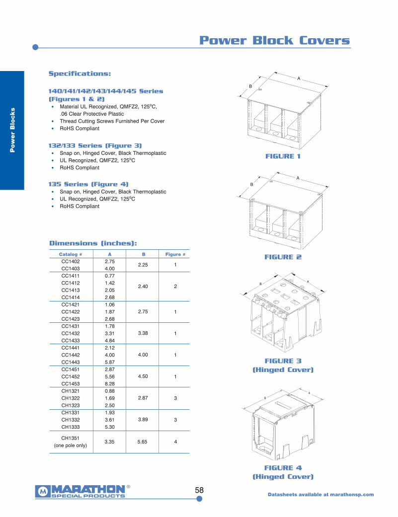
Power Block Covers
Datasheets available at marathonsp.com
A
B
AB
Specifications:
140/141/142/143/144/145 Series (Figures 1 & 2) • Material UL Recognized, QMFZ2, 125oC, .06 Clear Protective Plastic • Thread Cutting Screws Furnished Per Cover • RoHS Compliant
132/133 Series (Figure 3) • Snap on, Hinged Cover, Black Thermoplastic • UL Recognized, QMFZ2, 125oC • RoHS Compliant
135 Series (Figure 4) • Snap on, Hinged Cover, Black Thermoplastic • UL Recognized, QMFZ2, 125oC • RoHS Compliant
AB
Dimensions (inches):
Catalog # A B Figure # CC1402 2.75
1 CC1403 4.00 CC1411 0.77 CC1412 1.42
2 CC1413 2.05 CC1414 2.68 CC1421 1.06 CC1422 1.87 1 CC1423 2.68 CC1431 1.78 CC1432 3.31 1 CC1433 4.84 CC1441 2.12 CC1442 4.00 1 CC1443 5.87 CC1451 2.87 CC1452 5.56 1 CC1453 8.28 CH1321 0.88 CH1322 1.69 3 CH1323 2.50 CH1331 1.93 CH1332 3.61 3 CH1333 5.30
FIGURE 1
FIGURE 3(Hinged Cover)
FIGURE 2
A
B
FIGURE 4(Hinged Cover)
CH1351 (one pole only)
43.35 5.65
2.25
2.40
2.75
3.38
4.00
4.50
2.87
3.89
59
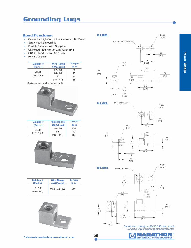
Grounding Lugs
Pow
er B
locks
Specifications: • Connector, High Conductive Aluminum, Tin Plated • Screw head is green ink • Flexible Stranded Wire Compliant • UL Recognized File No. ZMVV2.E43665 • CSA Certified File No. 63510-25 • RoHS Compliant
C MSA
9807052
5/16-24 SET SCREW
2-14 CUAL
.25[6.4]
Ø .266[6.75]
1.15[29.2]
.90[22.9]
.16
[4.0]
1.40[35.6]
.59[15.1]
Ø .31[7.9]
.23[5.9]
.50[12.7]
.25[6.3]
#2 - #3 50 #4 - #6 45 #8 40 #10 - #14 35
Catalog # (Part #)
Wire RangeAWG/kcmil
Torquelb in
GL02(9807052)
GL02:
SACM 9819830
CUAL 350MCM-6
Ø .531[13.49]
.56[14.3]
1.13[28.6]
.25[6.4]
.56[14.3]
1.69[42.9]
.50[12.7]
1.13[28.6]
1.25[31.8]
2.25[57.2]
.54[13.7]
Ø .72[18.3]
5/16 HEX SOCKETGL35:
CSAM
2/0-14 CUAL
M9718102
2/0-14 CUAL
Ø .44[11.1]
.44[11.1]
Ø .406[10.32]
.32[8.2]
.75[19.1]
.61[15.5]
.31[7.7]
1.63[41.3]
.25[6.4]
1.00[25.4]
1.31[33.3]
3/16 HEX SOCKETGL20:
350 kcmil - #6 375
Catalog # (Part #)
Wire RangeAWG/kcmil
Torquelb in
GL35(9819830)
2/0 - #6 120 #8 40 #10 - #14 35
Catalog # (Part #)
Wire RangeAWG/kcmil
Torquelb in
GL20(9718102)
For electronic drawings or 2D/3D CAD data, submit request at www.marathonsp.com/drawings.html
Slotted or hex head screw available
Datasheets available at marathonsp.com