power 22 - hotfoil-ehs · power 22 operations manual ... ix. parts breakdown ... c. hot sparks or...
TRANSCRIPT


ii
Dual Operator - Welding Machine
POWER 22
OPERATIONS MANUAL
R1 R2 Amps Volts
Remote Panel
Remote
POWER
AVAILABLE
ON
OFF
POWER
ON
FAN
RESET
45
40
35 30 25
20
10
5
15
0
REMOTE
150
100
OFF
200
150
100
5045
40
35 30 25
20
10
5
15
0
REMOTE
OFF
200
50
75
50
25
HILO
75
50
25
HILO
R1 R2 Amps Volts
Remote Panel
Remote
For Further assistance, call, write, or fax
Aftek Inc.
1714 Lafayette Road

iii
Fort Oglethorpe, GA 30742
Phone: (706) 861-9396
Toll FREE: (800) 742-5458
Fax: (706) 861-9943

iv

v
WARNING
OPERATOR / USER RESPONSIBILITY This equipment will perform in conformity with the description thereof contained in this manual and accompanying labels and/or inserts when installed, operated, maintained and repaired in accordance with the instructions provided. This equipment must be checked periodically. Defective equipment should not be used. Parts that are broken, missing, plainly worn, distorted or contaminated should be replaced immediately. Should such repair or replacement become necessary, Advanced Fusion Technologies ( Aftek ) recommends that a request for service advice be made to the Aftek authorized distributor from whom purchased or directly to the Aftek home office. RETURN MATERIAL AUTHORIZATION

vi
A. No equipment and/or parts will be accepted by Aftek when returned unless prior
authorization has been granted by the product support department. All equipment, and/or parts must be returned freight prepaid.
B. Warranty parts may, at the discretion of the product support department be shipped
prior to the return of the defective parts. The parts will be invoiced to the customer at their established prices, and a credit memo will be issued only upon receipt of the defective material at Aftek. In no event will Aftek issue a credit memo for any returned material if that material has not been returned to Aftek within sixty (60) days of authorization. At that time, the invoice issued will be due and payable.
C. The product support dept. of Aftek, upon receipt of defective items. will evaluate and
have final authorization as to the validity of the warranty claim. D. Upon receipt of authorized equipment at Aftek that is not covered under warranty,
Aftek personnel will inspect the equipment and an estimate of repairs will be made. This will be transmitted to the customer prior to any work being performed by Aftek , and, upon customer authorization, a purchase order will be requested.
FREIGHT CLAIMS Under federal ICC regulations, goods shipped F.O.B. point of origin are the property of the buyer, therefore, Aftek cannot file freight claims for damage to goods during shipment. Aftek is not authorized or allowed to do so. IMPORTANT NOTE: It is the responsibility of the customer to ensure that all internal electrical connections are tight on initial installation, and, further, to inspect tightness of connections at periodic intervals. Aftek engineering will assist in formulating these requirements, depending on application of the product.

TABLE OF CONTENTS
I. SAFETY PRECAUTIONS ..........................................................................................3
II. INTRODUCTION ......................................................................................................6
III. INSTALLATION .....................................................................................................6
IV. CONTROL LOCATIONS AND DESCRIPTIONS..................................................8
V. GENERAL OPERATING INSTRUCTIONS ..........................................................11
VI. SECONDARY CABLE CONNECTIONS ..............................................................16
VII. MAINTENANCE...................................................................................................17
VIII. TROUBLESHOOTING GUIDE .........................................................................19
IX. PARTS BREAKDOWN...........................................................................................21
X. SCHEMATIC............................................................................................................23

2

3
I. SAFETY PRECAUTIONS
WARNING: These safety precautions are for your protection. Before performing any installation or
operating procedures, be sure to read and follow the safety precautions listed below. Failure to observe
these safety precautions can result in personal injury or death.
1. PERSONAL PROTECTION: Skin and eye burns from exposure to rays from an electric arc or
hot metal can be more severe than sunburn. Therefore:
a. Use a face shield fitted with the correct filter and cover plates to protect your eyes, face,
neck, and ears from sparks and rays of the arc when operating or observing operations.
WARN bystanders not to watch the arc and not expose themselves to the rays of the electric
arc or hot metal.
b. Wear flameproof gauntlet-type gloves, heavy long- sleeve shirts, cuffless trousers, high-
topped shoes, and a welding helmet or cap for hair protection, to protect against arc rays and
sparks of hot metal. A flameproof apron may be desirable as protection against radiated heat
and sparks.
c. Hot sparks or metal can lodge in rolled up sleeves, trouser cuffs, or pockets. Sleeves and
collars should be kept buttoned and pockets eliminated from the front of clothing.
d. Protect other nearby personnel from arc rays and hot sparks with a suitable non-flammable
partition.
e. Always wear safety glasses or goggles when in a work area. Use safety glasses with side
shields or goggles when chipping slag or grinding. Chipped slag may be hot and can travel
considerable distances. Bystanders should also wear safety glasses or goggles.
f. Some gouging and cutting processes produce excessively high noise levels and require ear
protection.
2. FIRE PREVENTION: Hot slag or sparks can cause serious fires when in contact with combustible
solids, liquids, or gases. Therefore:
a. Remove all combustible materials well away from the work area or completely cover the
materials with a protective non-flammable covering. Such combustible materials include
wood, clothing, sawdust, gasoline kerosene, paints, solvents, natural gas, acetylene, propane,
and other similar materials.
b. Hot sparks or hot metals can fall into cracks in floors or wall openings and cause a hidden
smoldering fire. Make certain that such openings are protected from hot sparks and metal.
c. Do not weld, cut or perform other hot work until the workplace has been completely cleaned
so that there are not substances on the workplace which might produce flammable or toxic
vapors.
d. For fire protection, have fire extinguishing equipment (such as a garden hose, water pail, sand
bucket, or portable fire extinguisher) handy for instant use.
4
e. After completing operations, inspect the work area to make certain there are no hot sparks or
hot metal which could cause a later fire.
f. For additional information, refer to NFPA Standard 51B, "Fire Prevention in Use of Cutting
and Welding Processes", which is available from the National Fire Protection Association,
470 Atlantic Avenue, Boston MA 02210.
3. ELECTRICAL SHOCK: Contact with live electrical parts can cause severe burns to the body or
fatal shock. Severity of electrical shock is determined by the path and amount of current through the
body. Therefore:
a. Never allow live metal parts to touch bare skin or any wet clothing. Be sure gloves are dry.
b. When standing on metal or operating in a damp area, make certain that you are well insulated
from electrical shock. Wear dry gloves and rubber soled shoes and stand on a dry board or
platform.
c. Always ground the power supply by connecting a ground wire between the power supply and
an approved electrical ground.
d. Do not use worn or damaged cables. Do not overload the cable. Use well-maintained
equipment.
e. When not operating, turn off the equipment. Accidental grounding can cause overheating and
create a fire hazard. Do not coil or loop cable around parts of the body.
f. Be sure the proper size ground cable is connected to the workpiece as close to the work area
as possible. Grounds connected to building framework or other remote locations from the
work area increase the possibility of output current passing through lifting chains, crane
cables, or various electrical paths.
g. Keep everything dry, including clothing, work area, cables, electrode holder, and power
supply. Fix water leaks immediately.
h. Refer to American National Standard Z49.1 in Item 6 below for specific grounding
recommendations. Do not mistake the work lead for a ground cable.
4. VENTILATION: Fumes, particularly in confined spaces, can cause discomfort and physical harm.
Do not breath fumes. Therefore:
a. At all times provide adequate ventilation in the work area by natural or mechanical
ventilation means. Do not weld, cut or gouge on materials such as galvanized zinc, lead,
beryllium, or cadmium unless positive mechanical ventilation is provided. Do not breath
fumes from these materials.
b. Do not operate in locations close to chlorinated hydrocarbon vapors. These vapors typically
are found in degreasers or solvents. The vapors from these materials may burn in
combination with the welding arc to form phosgene, a highly toxic gas, or other irritating
gases.
c. If you develop momentary eye, nose, or throat irritation while operating, this is an indication
that ventilation is not adequate. Stop work and take necessary steps to improve ventilation in
the work area. Do not continue to operate if physical discomfort persists.
5
d. Refer to American National Standard Z49.1 (ANSI) in Item 6 below for specific ventilation
recommendations.
5. EQUIPMENT MAINTENANCE: Faulty or improperly maintained equipment can result in poor
work, but most importantly it can cause physical injury or death through fires or electrical shock.
Therefore:
a. Always have qualified personnel perform the installation, troubleshooting, and maintenance
work. Do not perform any electrical work unless you are qualified to perform such work.
b. Before performing any maintenance work inside a power supply, disconnect the power
supply from the electrical power source.
c. Maintain cables, grounding wire, connections, power cord and power supply in safe working
order. Do not operate any equipment in faulty conditions.
d. Do not abuse any equipment or accessories. Keep equipment away from heat sources such as
furnaces, wet conditions such as water puddles, oil or grease, corrosive atmospheres and
inclement weather.
e. Keep safety devices and cabinet covers in position and in good repair.
f. Use equipment for its intended purpose. Do not modify it in any manner.
6. ADDITIONAL SAFETY INFORMATION: For more information on safe practices for setting up
and operating electrical welding and cutting equipment, and on good working habits, the following
publications are available from the American Welding Society, 2501 NW 7th Street, Miami, Florida
32125:
a. "Safety in Welding and Cutting" AWS Z49.1 (ANSI)
b. "Recommended Safe Practices for Gas-Shielded Arc Welding" AWS A.6.1.
c. "Recommended Safe Practices for the Preparation for Welding and Cutting of Containers and
Piping that have held Hazardous Substances" AWS F4.1.
d. "Recommended Safe Practices for Plasma Arc Cutting" AWS A6.3.
e. "Recommended Safe Practices for Plasma Arc Welding" AWS C5.1.
f. "Recommended Safe Practices for Air Carbon Arc Gouging and Cutting" AWS C5.3.
g. "Arc Welding Safely" booklet.
6
II. INTRODUCTION
The Aftek Power 22 (P22) is part of a family of multiple operator welding units designed to give the
shipyard, power plant, paper mill, petrochemical, and general contractor industries the flexibility and
portability of a dual operator machine. Depending on the options selected SMAW ( stick electrode),
GTAW (TIG), FCAW (flux cored), and GMAW (hard wire MIG) applications may be performed by either
station. The basic configuration is set up for use with SMAW and Arc gouging also with the use of a
voltage sensing wire feeder the weldor may perform MIG welding. If a voltage sensing wire feeder is not
available then the Demand Pulse Mig option may be added to allow the use of a constant velocity wire
feeder.
The DC open circuit voltage is a nominal 80 open circuit volts. The P22 consists of one 500 amp
transformer and two rectifiers rated at 100 percent duty cycle. This unit is design to supply two separate
arcs. Each operator has separate controls and welds independent of the other arc.
PROTECTIVE FEATURES
Thermal controls are provided for the protection of the main transformer. In the event a prolonged
overheating situation arises the thermal switches will shut the unit down and allow a cooling period. The
thermal switches automatically reset themselves in approximately 3-5 minutes and require no maintenance.
III. INSTALLATION
UNIT LOCATION AND MAINTENANCE
Aftek power sources are housed in weather resistant steel casings and may be located either inside or
outside most structures. Ideally units should be located away from high traffic areas. An unobstructed air
flow is the only mandatory requirement, in terms of location of the unit, to insure proper operation. In areas
of high dust, intense rain or humidity, extra precautions must be taken. Contact the factory for more
information.
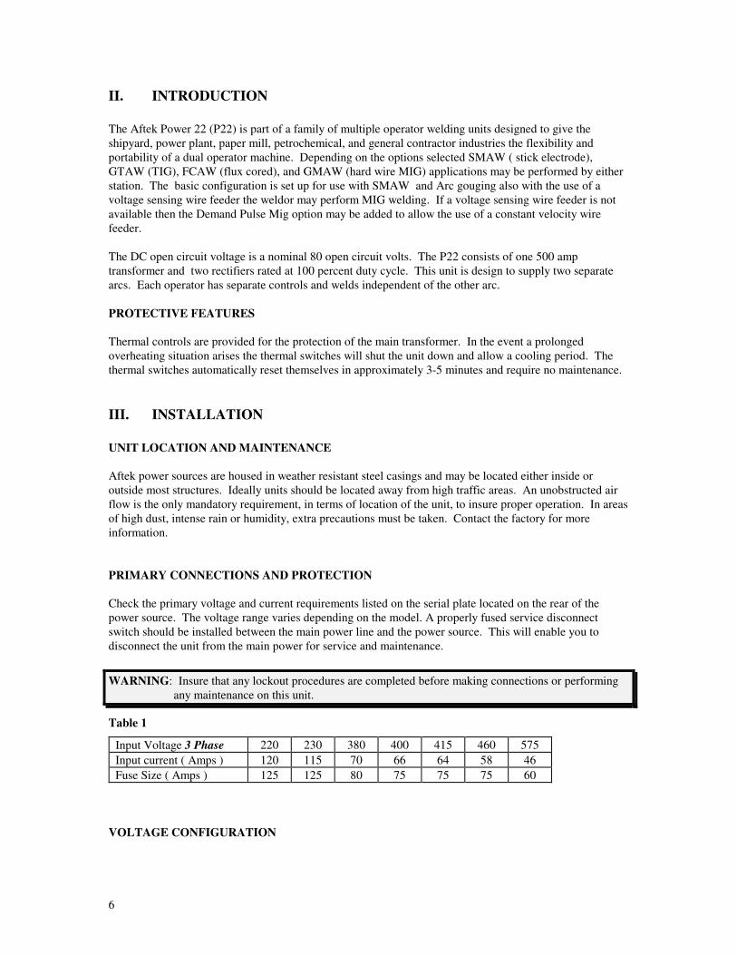
PRIMARY CONNECTIONS AND PROTECTION
Check the primary voltage and current requirements listed on the serial plate located on the rear of the
power source. The voltage range varies depending on the model. A properly fused service disconnect
switch should be installed between the main power line and the power source. This will enable you to
disconnect the unit from the main power for service and maintenance.
WARNING: Insure that any lockout procedures are completed before making connections or performing
any maintenance on this unit.
Table 1
Input Voltage 3 Phase 220 230 380 400 415 460 575
Input current ( Amps ) 120 115 70 66 64 58 46
Fuse Size ( Amps ) 125 125 80 75 75 75 60
VOLTAGE CONFIGURATION

7
Power sources are available in single, dual, and trivoltage depending upon the model. If equipped with
multiple voltage transformers the units are shipped from the factory with the change over links in the
highest voltage position. The voltage changeover board is located behind the side panel.
WARNING: The connections on the primary terminal board must correspond with the line voltage to be
used. Improper voltage settings could result in damage to the unit.
Figure 1
Tap board arrangement for 230/460/575 Volt primary input
230V 460V 575V
Tap board arrangement for 380/400/415 Volt primary input
380V 400V 415V
Tap board arrangement for 220/380/440 Volt primary input
220V 380V 440V
INPUT CABLE

8
A four wire input cable should be brought through the rear of the unit. Connect the three primary wires to
the brass studs labeled L1, L2, and L3. A grounding bolt is provided for the fourth ground wire.
Figure 2
Customers fused line disconnect Switch
Caution:Make sure all input power is
disconnected before performing anyoperation inside the welder.
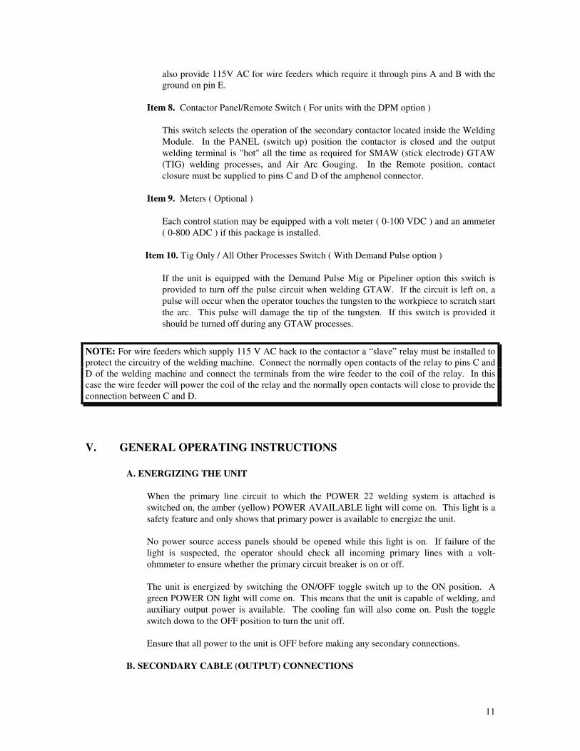
IV. CONTROL LOCATIONS AND DESCRIPTIONS
Item 1. Fan Reset
This circuit breaker is provided to stop fault situations in the control circuit.
Item 2. Power available light
The Power Available light ( amber ) is illuminated when the primary power is supplied
to the unit.
Warning: Never perform work on the unit while the Power Available light is on or there is reason to
suspect a failure of the light. This light is provided as an indicator only and should not take the place of an
electrical meter if work is to be performed on the unit.
Item 3. On / Off switch
The ON/OFF switch controls the power to the main contactor and the POWER ON
LIGHT. When the switch is placed in the On position the Power On Light is
illuminated and the control stations are ready for welding. The main transformer and
rectifiers are protected with thermal switches so that if in the event of prolonged
overheating the unit may shut power off to the welding terminals while leaving power
on to the unit’s cooling fan.
Item 4. Power On Light

9
A Power On light ( green ) is illuminated when the power switch is placed in the on
position.
Figure 3
POWER
AVAILABLE
ON
OFF
POWER
ON
FAN
RESET
12 3
4
CONNECTIONS
Primary connections and the voltage link board ( if so equipped) are located behind the right side panel.
Secondary connections, or DC output studs, are located behind the hinged terminal covers.
CONTROL STATION
Caution: The power supply must be off before making any connections to the welding output
terminals.
Item 1. 200 Amp Coarse Control
This rotary switch adjusts the amperage in 50A increments from 0A to 200A.
Item 2. 45 Amp Fine Control
This rotary switch adjusts the amperage in 5A increments from 0 to 45 Amps.
NOTE: THE AMPERAGE RATINGS SHOWN ON THE FRONT OF THE
WELDING MODULES ARE EXACT ONLY WHEN THE ARC VOLTAGE
IS EXACTLY WHAT THE RESISTOR ELEMENTS ARE DESIGNED TO
PROVIDE (30 ARC VOLTS). FOR THOSE WELDING OPERATIONS
WHERE THE ARC VOLTAGE IS LOWER THAN 30 ARC VOLTS, THE
ACTUAL OUTPUT AMPERAGE WILL BE HIGHER THAN THAT
SHOWN ON THE PANEL. FOR THOSE WELDING AND GOUGING
OPERATIONS WHERE THE ARC VOLTAGE IS HIGHER THAT 30 ARC
VOLTS, THE ACTUAL AMPERAGE OUTPUT WILL BE LOWER THAN
SHOWN. THE AMPERAGES SHOWN ON THE PANELS ARE TO BE
USED AS A GUIDE ONLY.
Item 3. Demand Pulse Control ( For units with the DPM option )
This one turn potentiometer allows the operator to select the arc voltage at which the
patented DEMAND PULSE circuit turns on to prevent short circuiting of the welding
arc. This function is explained in detail in the TECHNICAL section of this manual.
Item 4. R1 & R2 LED ( For units with the DPM option )

10
The R1 light emitting diode (LED) indicates the operation of the DEMAND PULSE circuit.
Each time the LED turns on indicates that the circuit is "kicking" the welding arc.
The R2 light emitting diode (LED) indicates the operation of the second DEMAND PULSE
MODULE. The second module is factory set to turn on when the arc voltage tries to fall
below 12 arc volts. This additional fixed DEMAND PULSE MODULE is necessary to
ensure quality welds in all position with hard wire MIG.
Figure 4
R1 R2
Amps Volts
Remote Panel
Remote
REMOTE
0
15
5
10
20
253035
40
45
50
100
150
200
OFF
LOHI
25
50
75
1 2
3
4
5 67 8
Plus (+) Minus (-)
9
Tig Only
All Other
Processes
10
CAUTION: In the event two welding power sources are connected to the same workpiece a condition may
occur such that there will be twice the open circuit voltage between the electrode holders. To prevent this,
the power sources must be connected on the same polarity. Consult the regulations of the Occupational
Safety and Health Act of 1971 ( OSHA ) for complete details.
Item 5-6. OUTPUT TERMINALS
The operator attaches his welding leads to these connections.
Item 7. Contactor ( For units with the DPM option )
This five (5) pin amphenol allows a wire feeder to be connected to the secondary
contactor provided inside the Welding Module through pins C and D. This connector
11
also provide 115V AC for wire feeders which require it through pins A and B with the
ground on pin E.
Item 8. Contactor Panel/Remote Switch ( For units with the DPM option )
This switch selects the operation of the secondary contactor located inside the Welding
Module. In the PANEL (switch up) position the contactor is closed and the output
welding terminal is "hot" all the time as required for SMAW (stick electrode) GTAW
(TIG) welding processes, and Air Arc Gouging. In the Remote position, contact
closure must be supplied to pins C and D of the amphenol connector.
Item 9. Meters ( Optional )
Each control station may be equipped with a volt meter ( 0-100 VDC ) and an ammeter
( 0-800 ADC ) if this package is installed.
Item 10. Tig Only / All Other Processes Switch ( With Demand Pulse option )
If the unit is equipped with the Demand Pulse Mig or Pipeliner option this switch is
provided to turn off the pulse circuit when welding GTAW. If the circuit is left on, a
pulse will occur when the operator touches the tungsten to the workpiece to scratch start
the arc. This pulse will damage the tip of the tungsten. If this switch is provided it
should be turned off during any GTAW processes.
NOTE: For wire feeders which supply 115 V AC back to the contactor a “slave” relay must be installed to
protect the circuitry of the welding machine. Connect the normally open contacts of the relay to pins C and
D of the welding machine and connect the terminals from the wire feeder to the coil of the relay. In this
case the wire feeder will power the coil of the relay and the normally open contacts will close to provide the
connection between C and D.
V. GENERAL OPERATING INSTRUCTIONS
A. ENERGIZING THE UNIT
When the primary line circuit to which the POWER 22 welding system is attached is
switched on, the amber (yellow) POWER AVAILABLE light will come on. This light is a
safety feature and only shows that primary power is available to energize the unit.
No power source access panels should be opened while this light is on. If failure of the
light is suspected, the operator should check all incoming primary lines with a volt-
ohmmeter to ensure whether the primary circuit breaker is on or off.
The unit is energized by switching the ON/OFF toggle switch up to the ON position. A
green POWER ON light will come on. This means that the unit is capable of welding, and
auxiliary output power is available. The cooling fan will also come on. Push the toggle
switch down to the OFF position to turn the unit off.
Ensure that all power to the unit is OFF before making any secondary connections.
B. SECONDARY CABLE (OUTPUT) CONNECTIONS

12
The output terminals for the operator's welding leads are located inside the terminal cover
located on the bottom right side of each welding module.
It is important that properly sized cables be used for both the electrode and ground. The
following table may be used as a guide for the selection of the cables for both the electrode
and ground leads. It is to be noted the "voltage drop" value refered to is for the entire weld
circuit; that is, for the length of the electrode cable PLUS the length of the ground cable.
Table 2. WELDING AND GROUND CABLE SELECTION
Conductor
Size (AWG)
Current
(Amps)
Voltage drop
per 100 ft.
2 225 3.75
1 280 3.50
1/0 340 3.37
2/0 420 3.29
3/0 505 3.17
4/0 605 3.13
C. AUXILIARY 115VAC HOOKUP
15 amps of 115 VAC is provided for operator use to run lights, grinders, or wire feeders,
through the GFI duplex outlet located on the bottom front of the POWER 22.
The 115VAC operates only when the ON/OFF switch is in the ON position, and the
welding system is fully energized.
D. WIRE FEEDER HOOKUP
For those operators needing to utilize the MIG welding process, there are two (2) options:
1. To weld with most flux cored wires, a voltage sensing wire feeder available from
several manufacturers is adequate.
To hook up the unit, the input power required to operate the feeder will be obtained
from the ELECTRODE terminals on the front of the Welding Module. Follow the
manufacturer's instructions to successfully operate these feeders.
2. On welding modules equiped with the DPM option, a secondary contactor is factory
installed so that any standard 115VAC wire feeder or CC/CV voltage sensing wire
feeder without a contactor may be used.
To properly connect on of these feeders, contact closure must be obtained between
pins C and D in the REMOTE amphenol connector located on the bottom left of the
Welding Module. The power to run the wire feeder (115 V AC) is provided through
pins A and B of the connector while pin E serves as the ground.
If a feeder is to be used that does not provide contact closure, a "slave" relay must
be added between pins C and D and the wire feeder ( consult your feeder manual or
manufacturer for this information). In other words, if the feeder to be used supplies
13
only 115VAC for the contactor operation, connect the coil of a 115 V AC relay it’s
terminals and the relay’s normally open contacts to pins C and D.
A five (5) pin male amphenol cable connector is provided with each of the Welding
Modules with this option for customer convenience in connecting to the wire feeder.
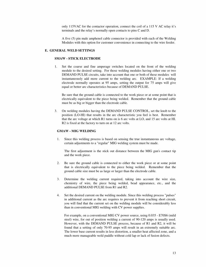
E. GENERAL WELD SETTINGS
SMAW - STICK ELECTRODE
1. Set the coarse and fine amperage switches located on the front of the welding
module to the desired setting. For those welding modules having either one or two
DEMAND PULSE circuits, take into account that one or both of these modules will
instantaneously add more current to the welding arc. EXAMPLE: If a welding
electrode normally operates at 95 amps, setting the output for 75 amps will give
equal or better arc characteristics because of DEMAND PULSE.
Be sure that the ground cable is connected to the work piece or at some point that is
electrically equivalent to the piece being welded. Remember that the ground cable
must be as big or bigger than the electrode cable.
3. On welding modules having the DEMAND PULSE CONTROL, set the knob to the
position (LO-HI) that results in the arc characteristic you feel is best. Remember
that the arc voltage at which R1 turns on is 6 arc volts at LO, and 15 arc volts at HI.
R2 is fixed at the factory to turn on at 12 arc volts.
GMAW - MIG WELDING
1. Since this welding process is based on sensing the true instantaneous arc voltage,
certain adjustments to a "regular" MIG welding system must be made.
The first adjustment is the stick out distance between the MIG gun's contact tip
and the work piece.
2. Be sure the ground cable is connected to either the work piece or at some point
that is electrically equivalent to the piece being welded. Remember that the
ground cable size must be as large or larger than the electrode cable.
3. Determine the welding current required, taking into account the wire size,
chemistry of wire, the piece being welded, bead appearance, etc., and the
additional DEMAND PULSE from R1 and R2.
4. Set the desired current on the welding module. Since this welding process "pulses"
in additional current as the arc requires to prevent it from reaching short circuit,
you will find that the current set on the welding module will be considerably less
than in conventional MIG welding with CV power supplies.
For example, on a conventional MIG CV power source, using 0.035 - E70S6 (mild
steel) wire, for out of position welding a current of 90-120 amps is usually used.
However, with the DEMAND PULSE process, because of R1 and R2, it will be
found that a setting of only 70-95 amps will result in an extremely suitable arc.
The lower base current results in less distortion, a smaller heat affected zone, and a
much more manageable weld puddle without cold lap or lack of fusion defects.

14
In the DEMAND PULSE welding process, the arc voltage is sensed between the
end of the contact tip and the work piece. Consequently, having too much stick
out, as shown in the following figure, will give the system an incorrect reading,
whereas a proper extension of the tip will result in a truer sense of the real arc
voltage and, at the same time, provide more operator visibility of the arc and
lessen the effects of wire cast and helix.
5. Select the desired shielding gas and adjust the flow rate for 20-30 CFH. Excessive
flow rates (40 CFH and over for the common shielding gases) will not only waste
gas, but will affect the weld bead (like welding in a hurricane).
Figure 5 RECOMMENDED POSITION OF CONTACT TIP
Gas cup
Contact tip
Sensed
Arc voltage
Workpiece
SensedArc voltage
Contact tip
Extended
1/16" to 1/4"
Beyond gas cup
6. Wire Feed Setting - In the DEMAND PULSE welding process, the arc voltage
(length of arc) is determined entirely by the speed of the wire being fed. If the
wire is being fed too fast, wire stubbing will occur. If the wire is being fed too
slow, the arc will have a tendency to burn back into the contact tip. You will find
that there is a "window" of wire feed speed where a desirable arc will be produced.
The fast end of the window will result in stubbing if the welding gun is suddenly
moved into a "wall". The slow end of the window will result in a very long,
unmanageable arc. It has been found that in welding with mild steel wire that the
best wire speed for overhead and vertical welding is on the fast side of the
"window". If wire feed speed is on the slow side of the "window" it may result in
balling of the wire in the overhead position. If beaded shape is of prime concern,
adjust the wire feed speed to give the bead profile desired. For a very flat bead,
wire speed must be slowed down to where the welding arc sounds like a cross
between globular and spray.
7. Place the DEMAND PULSE CONTROL knob at the setting resulting in the
welding arc you feel is best. Remember that the arc voltage at which R1 turns on
is 6 volts at LO and 15 volts at HI. R2 is factory fixed at 12 arc volts.
15
FCAW - FLUX CORED MIG
1. In welding with flux cored wire it has been found that welding at the fast end of
the "window" will cause stubbing if the operator dramatically shortens the stick
out. The surest way to set the wire feed speed properly is to adjust the wire speed
to the proper voltage required by the wire being used.
2. Because flux cored wires usually are designed for higher arc voltages (21 - 30V),
the R1 and R2 turn on voltages may be lower than desired, so the DEMAND
PULSE CONTROL knob should be set between 75 and HI. If flux core is the
only wire to be run, the factory should be consulted to determine what "turn on"
voltages are recommended. The "turn on" voltages are adjustable at the factory.
F. WELDING HINTS: DO'S AND DO NOT'S
DO'S
1. Connect the ground cable at a point where it is electrically the same as the work piece.
2. Position the contact tip so that it extends 1/16" to 1/4" beyond the end of the gun
nozzle.
3. Set the welding current (heat) at the Welding Module in GMAW *** Do not adjust
the wire feed speed for current.
4. Allow for the R1 and R2 circuits additional current pulses in setting the current on the
Welding Module.
5. Be sure that the wire feeds smoothly and consistently. Variations in wire feed speeds
will cause an erratic arc.
DO NOT'S
1. Increase the wire feed speed if more "heat" is wanted. If more current is required,
increase the current setting at the Welding Module. Increasing wire feed speed will
only result in lowering arc voltage and will cause stubbing.
2. Position the contact tip inside the end of the gas nozzle *** this results in a false arc
voltage to the system and, because of cast and helix in the wire, makes the operator
work a lot harder to keep a good looking bead.
3. Set gas flow too high or too low. The gas is used to shield the weld puddle only. If
there is too much gas, it will agitate the weld puddle, causing spatter and ropy welds.
Too little gas will result in porosity and "dirty" welds.
4. Overlook the ground connection *** be sure it is connected at a point where it is
electrically the same as the work piece.
5. Assume that the shielding gas is proper because the label on the bottle says so.
Contaminated bottles do exist.
6. Overlook leaks in the gas system or loose connections of fittings or holes in the gas
hoses will result in defective welds.

16
VI. SECONDARY CABLE CONNECTIONS
To obtain the full rated welding output from this system, it is necessary to select, install, and
maintain proper welding and ground cables. Failure to comply in any of these areas may
result in less than satisfactory welding performance. The following table give the
recommended electrode and ground cable sizes.
Table 3
RECOMMENDED WELDING AND GROUND CABLE SIZES
WELDING TOTAL LENGTH OF CABLE (COPPER) IN WELDING CIRCUIT
CURRENT 50 100 150 200 250 300 350 400
100 4 4 4 3 2 1 1/0 1/0
150 3 3 2 1 1/0 2/0 3/0 3/0
200 2 2 1 1/0 2/0 3/0 4/0 4/0
250 1 1 1/0 2/0 3/0 4/0 4/0 2-2/0
300 1/0 1/0 2/0 3/0 3/0 4/0 2-2/0 2-3/0
350 1/0 1/0 3/0 4/0 4/0 2-2/0 2-3/0 2-3/0
400 2/0 2/0 3/0 4/0 2-2/0 2-3/0 3-2/0 2-4/0
NOTES:
1. Cable size is based on direct current (DC) 60% duty cycle and either a four (4) volt or less drop or a
current density of not over 300 circular mils per amp.
2. Weld cable insulation with a voltage rating to withstand the open circuit voltage (OCV) of the welding
power source must be used. While most welding power sources have an open circuit voltage of less
than 100 volts, some welding power sources of special design may have higher open circuit voltages.

17
VII. MAINTENANCE
WARNING!!!
Before performing any maintenance or repair work on the unit, remove the line branch fuses or open
the wall disconnect switch or circuit breaker and perform the necessary lockout procedures. If it is
not possible to lockout the circuit then it should be at least red tagged. Turning the POWER switch
OFF does not remove the voltage from all points in the machine.
Routine maintenance and inspection is suggested to increase the reliability and extend the life of the
equipment. Inspection frequency is handled on a case by case basis, however, a maximum period between
routine inspections is 6 months, but depending on the area in which the unit is operating and the amount of
dust present, the inspections may be more frequent.
A. CLEANING
Periodically the side panels and covers should be removed and the accumulated dust blown out of the unit
with a clean dry source of compressed air. Particular attention should be paid to the rectifier heat sinks and
the main transformer as dust accumulation will hamper the cooling of these critical components. The
frequency between cleaning will depend largely on the location of the unit. Do not use any degreasing
compounds or water to clean the resistors in the unit, doing so will result in a fire or electrical shock hazard.
B. ELECTRICAL CONNECTIONS
The primary input cables and welding output cables should be periodically inspected for proper connection
and signs of overheating. It is important that the cables be properly sized and that the connections are tight.
Loose connections at the output of the module will result in a breakdown of the insulating material of the
connector and eventually a short. On units equipped with stud type terminals a wrench must be used to
tighten the connections. There should be no load on the output of the unit while connections are being
made, and it is recommended that the unit be turned off while making connections.
C. FAN MOTORS
Fan motors must be oiled annually. On units not equipped with oil ports, no lubrication is necessary.
D. VENTILATION
It is important that the unit get proper ventilation, this includes placing the unit so that none of the panels
are obstructed from air movement. All covers and panels must be in place to provide adequate air flow
direction over the components. Ventilation is provided by forced air, therefore, the fans must be inspected
for proper operation.
E. CONTROL CIRCUIT FUSES
If the on switch fails to energize the unit and it has been established that the line fuses are good, the problem
may be the control circuit fuses. Check these fuses only after opening the main disconnect switch. These
fuses are located by the voltage changeover tap board. Check across the fuses for continuity. Only replace
the fuse with one of the proper rating, a failure to do so may result in permanent damage to the unit.

18
F. RECTIFIER ASSEMBLY
During the periodic cleanings it is important to blow the accumulated dust off of the rectifier heat sinks.
The build up of dust on the heat sink reduces the amount of heat that the rectifier can dissipate. Cleaning
the rectifier periodically increases the life span of the diodes and helps prevent premature failures.
In the event of a diode failure, a visual inspection cannot be relied upon to determine whether a diode is
faulty. The proper way to check the diode is with a Volt-Ohmmeter. When using the meter insure the
meter is set on the lowest resistance scale or on the diode checking position if so equipped.
Inspection
1. Before checking the diodes it is necessary to remove the input cables from the transformer. If
the cables are not removed, the reading taken will be false. Only remove the cables from the
transformer to the input of the diodes ( the small end ). Do not loosen the large nuts connecting
the diode to the heat sink.
2. A diode has the property of conducting in only one direction, therefore if the diode conducts in
both directions or in neither direction it is considered faulty.
Replacement procedure
1. Before installing new diodes it is necessary to apply a thin coat of thermal joint compound to
the surface that mates with the heat sink. GC Type Z9 or the equivalent compound is to be
used. Only a thin coat of compound should be applied to the surface.
2. Fasten the diode the heat sink with a torque of approximately 25 foot-pounds.
3. Reconnect the input cables to the diode input with the hardware provided. For units equipped
with diodes that have a stud type input, torque the input nut to approximately 7 foot-pounds.
This bolt is made of soft copper and excessive tightening will damage the diode.
G. THERMAL OVERLOAD PROTECTION
The unit is provided with thermal overload protection on both the rectifiers and the transformer. In the case
that either is overload, the temperature will increase until either of the thermostats actuates. The thermal
switch is a normally closed devise that when overheated will open the circuit to the main contactor. When
this occurs allow approximately 5 minutes and the thermostat will automatically reset.

19
VIII. TROUBLESHOOTING GUIDE
TROUBLE PROBABLE CAUSE REMEDY
Line fuse blows after a short
period of operation
Line fuse too small Replace with recommended size
Line fuse blows as soon as
machine is turned on
Improper primary voltage tap
board connection
Refer to tap board change over
diagram and set tap board
Primary input conductors
connected improperly
Insure the ground is connected to
the ground leg of the plug
Faulty diode Replace diode
Arc fluctuates when another
welder starts
Not enough ground cable Run separate ground cables
Primary input cable too small Install proper size
Loose or improper ground
connection
Remove paint from ground area
and tighten connection
Erratic arc Poor ground or electrode cable
connection
If lugs heat up during operation
this shows a possible poor
connection. Re-crimp lug or
scrap paint from ground contact.
No output on one module Rectifier defective Replace faulty diodes
Arc erratic, both modules Blown line fuse Replace line fuse
Primary contactor defective Check the condition of the
contacts and replace contactor if
necessary
Fan motor runs slow Tap board set for improper
voltage
Connect to proper voltage
Low primary voltage Connect to proper voltage
Normal output, fan does not run Bad connection to fan motor lead Fix connection
Defective fan motor Replace fan motor

20
TROUBLE PROBABLE CAUSE REMEDY
No output , fan motor does not
run
Line fuse blown Replace fuse
Branch disconnect or circuit
breaker is open
Close disconnect or breaker
Power switch defective Replace switch
Fan runs, no output on either
module
Thermal switch has tripped Allow approximately 5 minutes
to cool
Defective contactor Replace contactor
No power at 115V outlet Circuit breaker tripped Reset breaker
Faulty outlet Replace outlet
Contactor of DPM module will
not engage
Improper connection to amphenol Refer to manual for hookup
instructions
Defective contactor Replace contactor
Defective contactor control board Replace circuit board

21
IX. PARTS BREAKDOWN
Item # Part # Description Qty. U/M
D4-D6 220251 Negative Diode 6 ea
D1-D3 220250 Positive Diode 6 ea
122007 Heatsink, P22 4 ea
151020 Glastic insulators 8 ea
T1 600350 Transformer, HV twin 250 230/460/575 1 ea
600351 Transformer, HV twin 250 220/380/440
600352 Transformer, HV twin 250 380/400/415
112600 Front panel, P22 1 ea
112601 Resistor baffle cover 1 ea
112602 Base, P22 1 ea
112603 Rear panel, P22 1 ea
112604 On/Off silk-screen panel P22 1 ea
112605 Resistor baffle, large hole P22 1 ea
112606 Resistor baffle, small hole P22 1 ea
112607 Silkscreen panel, module P22 2 ea
112608 Side panel, P22 2 ea
112609 Roof, P22 1 ea
112610 Lifting yoke, P22 1 ea
112611 Terminal cover, P22 2 ea
112612 Resistor locking bar, P22 2 ea
112613 Rectifier mounting tray, P22 1 ea
112614 Heat shield, P22 1 ea
112615 Fan mount, P22 1 ea
142240 Output copper, P22 4 ea
142241 Resistor input buss, P22 2 ea
151031 Tapboard w/input 1 ea
151216 Output insulator, P22 2 ea
142000 Tapborad links 10 ea
R1-R4 500160 Resistor, 1.0 ohm 8 ea
R7 500110 Resistor, 6.6 ohm 2 ea
R5 500112 Resistor, 10 ohm 2 ea
R6 500111 Resistor, 5 ohm 2 ea
SW1 264016 Switch, 300A Bremas 2 ea
SW2 264010 Switch, 45A Bremas 2 ea
804975 Wire set 200A switch 2 ea
804976 Wire set 45A switch 2 ea
FM1 240000 Fan motor, 1/4 Hp 1 ea
C1 244002 Capacitor, 5 Mfd 1 ea
246001 Fan blade, 16" 1 ea
T2 250200 Transformer, 0.5 KVA 230/460/575 1 ea
250203 Transformer, 0.5 KVA 220/380/440
250208 Transformer, 0.5 KVA 380/400/415
CR1 250004 Primary contactor 1 ea
186028 Fuse block 1 ea

22
F1-F2 186101 Fuse 15 KTK 2 ea
F3-F4 186102 Fuse 5 Amp, 250 Volt 2 ea
804977 Wiring harness 1 ea
SW1 260007 Switch, DPST 1 ea
LG1 228000 Light, Amber 1/2" 1 ea
LG2 228001 Light, Green 1/2" 1 ea
CB1 232000 Circuit breaker 5 Amp 1 ea
CB2 232002 Circuit Breaker 15 Amp 1 ea
230101 Outlet, 115V AC GFI 1 ea
230201 Outlet cover, GFI 1 ea
804978 Cable set 1 ea
289003 Label, "Lethal Voltages" 1 ea
289008 Label, "Warning" 1 ea
289004 Label, "Tapboard & Contactor" 1 ea
289005 Tapboard changeover 1 ea
Option " Pipeliner "
400300 Demand pulse board 1 ea
500160 Resistor, 1.0 ohm 1 ea
260005 Switch DPDT 30A 1 ea
228006 LED ( Red ) 1 ea
Option " Demand Pulse Mig "
400300 Demand pulse board 2 ea
500160 Resistor, 1.0 ohm 2 ea
260005 Switch DPDT 30A 1 ea
228006 LED ( Red ) 2 ea
250105 Contactor, 250A 1 ea
185009 Amphenol, panel mount case 1 ea
185016 Amphenol, 5 pin male insert 1 ea
Option Meter
239008 Shunt 800A 1 ea
259900 Ammeter, 0-800A DC 1 ea
259951 Voltmeter, 0-100V DC 1 ea
805015 Wiring harness, meter 1 ea

X. SCHEMATIC
18
17
60 V80 VDC
R1
2
R2
4
R3
6
R4
8
R5
2
R6
4
R7
6 8
Minus (-)Plus (+)
L3
L2
L1
230
460
575
115LG1
CB1
FM1C1
TS1
GND
T2
F3
F4
16
15
14
13
10
9
12
11
8
7
6
5
4
3
2
1
LG2
Power 22 230/460/575 Volts ( 16 Feb. 95 )
F1
F2
60 V80 VDC
R1
2
R2
4
R3
6
R4
8
R5
2
R6
4
R7
6 8
Minus (-)Plus (+)
T1
CR1
D1-D3
D4-D6
D1-D3
D4-D6
SW1
CB2
TS2
TS3TS2-TS3 Transformer thermal switches
SW2 SW3
SW2 SW3
GND