pow-r-line distribution switchboards - volume 2 provide electrical system distribution and metering...
TRANSCRIPT

Volume 2—Commercial Distribution CA08100003E—February 2018 www.eaton.com V2-T4-1
4
4
4
4
4
4
4
4
4
4
4
4
4
4
4
4
4
4
4
4
4
4
4
4
4
4
4
4
4
4
Switchboards
Pow-R-Line Group-Mounted Distribution Switchboard
4.1 Group-Mounted Switchboards
Pow-R-Line® Distribution Switchboards Product Description . . . . . . . . . . . . . . . . . . . . . . . . . . . . . . . . . . . . . . . V2-T4-2
Application Description . . . . . . . . . . . . . . . . . . . . . . . . . . . . . . . . . . . . V2-T4-2
Standards and Certifications . . . . . . . . . . . . . . . . . . . . . . . . . . . . . . . . V2-T4-2
Product Selection . . . . . . . . . . . . . . . . . . . . . . . . . . . . . . . . . . . . . . . . . V2-T4-2
Commercial Metering Switchboards Product Description . . . . . . . . . . . . . . . . . . . . . . . . . . . . . . . . . . . . . . . V2-T4-3
Application Description . . . . . . . . . . . . . . . . . . . . . . . . . . . . . . . . . . . . V2-T4-3
Standards and Certifications . . . . . . . . . . . . . . . . . . . . . . . . . . . . . . . . V2-T4-5
Product Selection . . . . . . . . . . . . . . . . . . . . . . . . . . . . . . . . . . . . . . . . . V2-T4-5
Technical Data and Specifications . . . . . . . . . . . . . . . . . . . . . . . . . . . . V2-T4-5
4.2 Integrated Facility Switchboards™
Product Description . . . . . . . . . . . . . . . . . . . . . . . . . . . . . . . . . . . . . . . . . . V2-T4-6
Application Description . . . . . . . . . . . . . . . . . . . . . . . . . . . . . . . . . . . . . . . V2-T4-6
Standards and Certifications . . . . . . . . . . . . . . . . . . . . . . . . . . . . . . . . . . . V2-T4-7
Product Selection . . . . . . . . . . . . . . . . . . . . . . . . . . . . . . . . . . . . . . . . . . . V2-T4-7
4.3 Pow-R-Line Drawout Molded Case Circuit Breaker Switchboards
Product Description . . . . . . . . . . . . . . . . . . . . . . . . . . . . . . . . . . . . . . . . . . V2-T4-8
Application Description. . . . . . . . . . . . . . . . . . . . . . . . . . . . . . . . . . . . . . . . V2-T4-8
Standards and Certifications . . . . . . . . . . . . . . . . . . . . . . . . . . . . . . . . . . . V2-T4-8
Product Selection . . . . . . . . . . . . . . . . . . . . . . . . . . . . . . . . . . . . . . . . . . . . V2-T4-9
Dimensions . . . . . . . . . . . . . . . . . . . . . . . . . . . . . . . . . . . . . . . . . . . . . . . . V2-T4-10
Options, Accessories and Modifications . . . . . . . . . . . . . . . . . . . . . . . . . . V2-T4-13
4.4 Compartmentalized Switchboards
Pow-R-Line i Distribution SwitchboardsProduct Description . . . . . . . . . . . . . . . . . . . . . . . . . . . . . . . . . . . . . . . V2-T4-15
Application Description . . . . . . . . . . . . . . . . . . . . . . . . . . . . . . . . . . . . V2-T4-15
Standards and Certifications . . . . . . . . . . . . . . . . . . . . . . . . . . . . . . . . V2-T4-16
4.5 Instant Service Switchboards
Product Description . . . . . . . . . . . . . . . . . . . . . . . . . . . . . . . . . . . . . . . . . . V2-T4-17
Application Description . . . . . . . . . . . . . . . . . . . . . . . . . . . . . . . . . . . . . . . V2-T4-17
Standards and Certifications . . . . . . . . . . . . . . . . . . . . . . . . . . . . . . . . . . . V2-T4-17
Product Selection . . . . . . . . . . . . . . . . . . . . . . . . . . . . . . . . . . . . . . . . . . . V2-T4-18
Accessories . . . . . . . . . . . . . . . . . . . . . . . . . . . . . . . . . . . . . . . . . . . . . . . . V2-T4-20
Technical Data and Specifications . . . . . . . . . . . . . . . . . . . . . . . . . . . . . . . V2-T4-21
Dimensions . . . . . . . . . . . . . . . . . . . . . . . . . . . . . . . . . . . . . . . . . . . . . . . . V2-T4-21
4.6 Roll-Up Generator Termination Box
Product Description . . . . . . . . . . . . . . . . . . . . . . . . . . . . . . . . . . . . . . . . . . V2-T4-22
Standards and Certifications . . . . . . . . . . . . . . . . . . . . . . . . . . . . . . . . . . . V2-T4-22
Technical Data and Specifications . . . . . . . . . . . . . . . . . . . . . . . . . . . . . . . V2-T4-23
Dimensions . . . . . . . . . . . . . . . . . . . . . . . . . . . . . . . . . . . . . . . . . . . . . . . . V2-T4-36
4.7 Power Xpert Multipoint Metering Switchboard
Overview . . . . . . . . . . . . . . . . . . . . . . . . . . . . . . . . . . . . . . . . . . . . . . . . . . V2-T4-37
Product Description . . . . . . . . . . . . . . . . . . . . . . . . . . . . . . . . . . . . . . . . . . V2-T4-37
Application Description. . . . . . . . . . . . . . . . . . . . . . . . . . . . . . . . . . . . . . . . V2-T4-37
Standards and Certifications . . . . . . . . . . . . . . . . . . . . . . . . . . . . . . . . . . . V2-T4-38
Product Selection . . . . . . . . . . . . . . . . . . . . . . . . . . . . . . . . . . . . . . . . . . . V2-T4-38
LearnOnline

Volume 2—Commercial Distribution, CA08100003E
Tab 4—SwitchboardsRevision date Section Change page(s) Description
10/24/2017 — V2-T4-1 Update Tab TOC10/24/2017 4.1 V2-T4-2 Content edit10/24/2017 4.3 V2-T4-9–V2-T4-13 Content edit10/24/2017 4.7 V2-T4-36, V2-T4-39 Content edit
02/08/2018 All All Revision date changed to February 2018
Revision notes

V2-T4-2 Volume 2—Commercial Distribution CA08100003E—February 2018 www.eaton.com
4
4
4
4
4
4
4
4
4
4
4
4
4
4
4
4
4
4
4
4
4
4
4
4
4
4
4
4
4
4
4.1 Switchboards
Group-Mounted Switchboards
Pow-R-Line Group-Mounted Distribution Switchboard ContentsDescription Page
Pow-R-Line Distribution SwitchboardsProduct Description . . . . . . . . . . . . . . . . . . . . V2-T4-2
Application Description . . . . . . . . . . . . . . . . . . V2-T4-2
Features, Benefits and Functions . . . . . . . . . . V2-T4-2
Standards and Certifications . . . . . . . . . . . . . . V2-T4-2
Product Selection . . . . . . . . . . . . . . . . . . . . . . V2-T4-2
Pow-R-Line Distribution SwitchboardsProduct DescriptionEaton’s Pow-R-Line distribution switchboards combine a space-saving design with modular construction and increased system ratings to provide economical and dependable electrical system distribution and protection.
Application DescriptionRefer to Eaton’s Consulting Application Guide.
Features, Benefits and Functions● 6000A maximum main
bus rating● 600 Vac and below● 600 Vdc and below● Front or rear accessible● Type 1 or Type 3R
enclosures● ANSI-61 gray powder
coat paint finish● Microprocessor-based
metering and monitoring devices
● Utility metering provisions● Surge protective devices
(SPD)● Ground fault protection
on mains and distribution devices
● Busway and transformer connections
● Complete protective device accessory capability
● 65 kAIC bus bracing standard; optional 100 or 200 kAIC
● Standard tin-plated aluminum bus; optional copper- or silver-plated copper bus● Standard bus ampacities
based on UL® heat test ratings. Optional density rated bus systems are also available
Main and Individually Mounted Devices● Magnum® SB insulated
case circuit breakers, 800–5000A, fixed or drawout
● Magnum DS power circuit breakers, 800–5000A, fixed or drawout
● Series NRX™ insulated circuit breaker, 400–3000A, fixed or drawout
● Molded case circuit breakers, 400–2500A, fixed mounted
● Bolted pressure switches, 800–5000A
● FDPW fusible switches, 400–1200A
Group-Mounted Distribution Devices● Molded case circuit
breakers, 15–1200A● FDPW fusible switches,
30–1200A
Standards and Certifications● Meets NEMA® Standard
PB-2 and UL 891● Seismically qualified
Product SelectionFor complete application and pricing information, contact your local Eaton sales office.

Volume 2—Commercial Distribution CA08100003E—February 2018 www.eaton.com V2-T4-3
4
4
4
4
4
4
4
4
4
4
4
4
4
4
4
4
4
4
4
4
4
4
4
4
4
4
4
4
4
4
4.1Switchboards
Group-Mounted Switchboards
WWCMS WCMS
Commercial Metering Switchboards ContentsDescription Page
Commercial Metering SwitchboardsFeatures, Benefits and Functions . . . . . . . . . . . V2-T4-4
Standards and Certifications . . . . . . . . . . . . . . V2-T4-5
Product Selection . . . . . . . . . . . . . . . . . . . . . . . V2-T4-5
Technical Data and Specifications . . . . . . . . . . V2-T4-5
Commercial Metering SwitchboardsProduct DescriptionEaton’s commercial metering switchboards provide electrical system distribution and metering for shopping centers, office buildings and other commercial multimetering applications.
Using standard Pow-R-Line construction and features, these switchboards incorporate metering sections with tenant feeder circuits using meter sockets to meet local utility or customer requirements.
All meter sockets and associated feeder devices are completely factory prewired and shipped ready for the installation of the meters.
Application Description
Type WWCMSFor EUSERC serviced areas. The self-contained meter sockets include a test bypass/disconnect block per EUSERC requirements, and are arranged, typically, for hot sequence metering.
Socket and Test Block Assembly
Type WCMSFor other than EUSERC serviced areas. Self-contained meter sockets are provided with manual lever bypass and can be arranged for either hot or cold sequence metering.
Socket with Manual Lever Bypass
Refer to Eaton’s Consulting Application Guide.

V2-T4-4 Volume 2—Commercial Distribution CA08100003E—February 2018 www.eaton.com
4
4
4
4
4
4
4
4
4
4
4
4
4
4
4
4
4
4
4
4
4
4
4
4
4
4
4
4
4
4
4.1 Switchboards
Group-Mounted Switchboards
Features, Benefits and FunctionsPow-R-Line designates a family of distribution switchboards, incorporating design concepts that fit the ever-increasing need for applications on high short-circuit systems, while retaining maximum safety and convenience throughout the line.
Front AccessibleFront-accessible switchboards align at the rear, enabling them to be placed against a wall (Pow-R-Line front accessible). If the main section is deeper than others, due to physical size of the main device, the necessary off-set in line-up will occur in front, and the main section will be accessible from the side as well as from the front. Standard front accessible switchboards will align at the front and rear.
Rear Accessible Rear-accessible switchboards align at the front and the rear. Bus maintenance and cable entry and exit require rear access. There are two types of rear accessible switchboards. Both types use the same incoming utility and/or main structures. The first type uses group-mounted feeder devices with panel construction (Pow-R-Line rear accessible). The second type uses individually compartmentalized feeder devices with load side insulated bus bar extensions (Pow-R-Line i).
Standard Switchboard HeightStandard Pow-R-Line switchboard height is 90 inches (2286.0 mm).
Group MountingGroup-mounted circuit protective devices are an assembly of units mounted on a panelboard type base (panelboard construction). Units may be molded case breakers, or FDPW fusible switches. Circuit protective devices are accessible from the front.
A main molded case breaker or main FDPW fusible switch, within the sizes listed for panelboard design, can be included in the panel-mounted assembly in lieu of a separate, individually mounted unit.
Space Only for Future Devices Group-Mounted ConstructionWhere space only for future circuit protective devices is required, the proper space and a blank filler plate will be supplied. Connections and mounting hardware are not included.
Provision for Future DevicesWhere provisions for future circuit protective devices are required, space for the device, corresponding vertical bus, device connectors and the necessary mounting hardware will be supplied.
Bus Bar SystemStandard bus in the switchboards is tin-plated aluminum. Copper and silver-plated copper are also available.
Main bus and sub-main buses meet UL and NEMA standards for temperature rise on all Pow-R-Line switchboards. Special bus densities are available.
Overcurrent DevicesTo properly select and size overcurrent devices for use in a switchboard, the allowable temperature rise must be taken into account as to its effect on the tripping characteristics of the devices in question.
Accordingly, Article 220 of the NEC® requires overcurrent devices to be rated not less than 125% of the continuous load they are protecting. To comply with this, an 80% derating factor must be used with all overcurrent devices such as molded case breakers and FDPW fusible switches unless they are tested and marked as 100% rated devices.
Short-Circuit RatingStandard bus and connectors on all switchboards are rated for use on systems capable of producing up to 65,000A rms symmetrical short-circuit current at the incoming terminals.
Increased bus short-circuit ratings equal to that of connected switchboard devices, up to 200,000A rms symmetrical, are availablein most Pow-R-Line switchboards when approved main devices are installed. Contact Eaton for more information. UL labeled switchboard sections are marked with their applicable short-circuit rating.
Provision for Busway Entrance and ExitBusway connections to switchboard sections include cutout and drilling in the top of the switchboard with riser connections from the switchboard device or bus, up to the point where the bus duct enters the switchboard. No connections are furnished external to the switchboard.
Note: In all transactions involving busway attached to switchboards, it is essential that information regarding orientation of the busway with respect to the front of the switchboard be supplied to the coordinating assembly plant.
On Pow-R-Line switchboards, solid bus bar is used to connect the bus duct to the individually mounted main device, main or sub-main switchboard bus, or vertical main bus of panel mounted circuit protective device panels. Busway fed by group-mounted branch devices are cable connected.
Aluminum riser connections are standard. Copper- or silver-plated copper is available as a modification.
TransitionsTransition structures are required for connecting switchboards to the secondary of power center transformer (dry or fluid filled), motor control centers, and for other special switchboard configurations such as “L” or “U” shaped lineups. In some application, an extra structure complete with connections is required; in others, where switchboard depth and space permit, only the connection conductors are required. Refer to factory for these applications.

Volume 2—Commercial Distribution CA08100003E—February 2018 www.eaton.com V2-T4-5
4
4
4
4
4
4
4
4
4
4
4
4
4
4
4
4
4
4
4
4
4
4
4
4
4
4
4
4
4
4
4.1Switchboards
Group-Mounted Switchboards
Standards and Certifications● UL 891● NEMA PB-2● Seismically qualified
Product SelectionFor complete application and pricing information, contact your local Eaton sales office.
Technical Data and Specifications
Service● 120/240V, single-phase,
three-wire● 240/120V, 208Y/120V,
415Y/240V, 480Y/277V or 600Y/347V three-phase, four-wire
● 600 Vdc
Main Bus Rating● 400–4000A
Service Section● Main circuit breaker,
400–4000A● Main fusible switch,
400–4000A● Main lugs only,
400–6000A
Metering Sections● Tenant main disconnects
and meter sockets (200A maximum self-contained metered circuits)
● Hot sequence metering circuits
● Cold sequence metering circuits (WCMS only)
● Optional rear barriered wireways or load side pull sections for cable exit requirements
● Sections for metered circuits larger than 200A available with 400A continuous rated self-contained sockets or with CT compartment and transformer rated socket in combination with disconnect

V2-T4-6 Volume 2—Commercial Distribution CA08100003E—February 2018 www.eaton.com
4
4
4
4
4
4
4
4
4
4
4
4
4
4
4
4
4
4
4
4
4
4
4
4
4
4
4
4
4
4
4.2 Switchboards
Integrated Facility Switchboards
Integrated Facility Switchboard ContentsDescription Page
Integrated Facility SwitchboardsFeatures, Benefits and Functions . . . . . . . . . . V2-T4-7
Standards and Certifications . . . . . . . . . . . . . . V2-T4-7
Product Selection. . . . . . . . . . . . . . . . . . . . . . . V2-T4-7
An EatonGreen Solution
Product DescriptionEaton’s Integrated Facility Switchboards use the modular Pow-R-Line group-mounted switchboard design to integrate traditionally separate electrical distribution and control equipment into a single space-saving factory assembled and connected package.
The service entrance equipment can be integrated with multiple lighting and appliance branch panelboards into a compact front-accessible group-mounted switchboard. Where multiple panelboards are used in the same electrical room as a conventional distribution switchboard or power panelboards, the integrated design will significantly reduce equipment space requirements, as well as reduce installation time and costs.
Other associated equipment can also be integrated into the assembly, including dry-type distribution transformers, Building Management Systems, Pow-R-Command™ lighting control system, electronic controls, surge protective devices, metering and energy monitoring devices. Depending upon the application, other user-defined equipment such as a subsystem control package may also be incorporated.
Application DescriptionEaton’s Integrated Facility Switchboards are designed to meet specific needs for:
● Retail chain stores● Commercial offices ● High rise buildings● Correctional facilities● Agricultural facilities● Industrial facilities● Hospitals/healthcare
facilities● Educational facilities
Whether the application is a multi-site prototype or single application, integrated switchboards offer time and space-saving features.
For complete application description, refer to Eaton’s Consulting Application Guide.

Volume 2—Commercial Distribution CA08100003E—February 2018 www.eaton.com V2-T4-7
4
4
4
4
4
4
4
4
4
4
4
4
4
4
4
4
4
4
4
4
4
4
4
4
4
4
4
4
4
4
4.2Switchboards
Integrated Facility Switchboards
Features, Benefits and FunctionsFront AccessibleIntegrated Facility Switchboards are front accessible and align at the rear, enabling them to be placed against a wall. Most switchboards align at the front and the rear. If the main section is deeper than others, due to physical size of the main device, the necessary off-set in line-up will occur in front, and the main section will be accessible from the side as well as from the front.
Standard Switchboard HeightSwitchboard height is 90 inches (2286.0 mm).
A limited offering of 78-inch (1981.2 mm) high equipment is available. Consult the factory for specific applications.
Switchboard Shipping SplitsThe sections can be shipped as specified by the customer to meet specific requirements.
For retrofit applications, single-piece switchboard structures can be shipped to facilitate movement through limited access doorways, etc.
Factory InterconnectionsMost sub-panels are fed from the main distribution panel feeder circuit breakers using copper cable sized per the NEC and UL.
Space SavingsThe space-saving switchboard installation provides additional usable floor space. For example:
● Retail stores—floor space for sales
● Offices—additional storage, cubicle
● Healthcare—additional work area
● Retrofits—ability to fit existing rooms
Traditionally Mounted Equipment
Site Construction SavingsTimely installation of the electrical system typically is a key element on the critical path for any project.
Along with the time to install the equipment, other expenses include the time to handle all of the loose pieces of equipment arriving on a job site and ensuring it reaches the proper trades person. With Eaton’s Integrated Facility Switchboards, one piece of equipment is typically shipped to a job site virtually eliminating these issues.
The equipment may also be used for temporary power on job sites, further reducing construction expenses and times.
Construction Savings
Standards and Certifications● Meets NEMA Standard
PB-2 and UL 891● Panelboards mounted
inside the sections meet NEMA PB-1 and UL 67
● Other equipment is UL listed as applicable and appropriate
Product SelectionFor complete application and pricing information, contact your local Eaton sales office.

V2-T4-8 Volume 2—Commercial Distribution CA08100003E—February 2018 www.eaton.com
4
4
4
4
4
4
4
4
4
4
4
4
4
4
4
4
4
4
4
4
4
4
4
4
4
4
4
4
4
4
4.3 Switchboards
Pow-R-Line Drawout Molded Case Circuit Breaker Switchboards
Pow-R-Line Drawout Molded Case Circuit Breaker Switchboards ContentsDescription Page
Pow-R-Line Drawout Molded Case Circuit Breaker Switchboards
Product Selection . . . . . . . . . . . . . . . . . . . . . . . V2-T4-9
Dimensions . . . . . . . . . . . . . . . . . . . . . . . . . . . . V2-T4-10
Options, Accessories and Modifications. . . . . . V2-T4-13
Product Description● Drawout molded case
circuit breaker switchboard● Front accessible● Front connected● Through-the-door design
drawout mechanism through 600A
● Insulated case UL 489 breakers up to 1200A
● Visual indication of breaker status and position
● Large grab handles for easy removal
● 600 Vac maximum● 600A maximum, group-
mounted, drawout molded case feeder breakers
● Individually mounted insulated UL 489 breakers through 1200A
Application Description● Drawout feeders in UL 891
distribution switchboards● Rated as Service Entrance
Equipment when appropriately equipped
● Ideal for:● Data centers● Industrial facilities● Process equipment
manufacturing ● Anywhere that requires
quick change of feeder devices is needed
Features, Benefits and FunctionsEaton’s Pow-R-Line Drawout switchboard design is listed and labeled to the UL 891 standard. Switchboards may be rated up to 4000A. Main breakers are available up to 4000A in both fixed-mounted and drawout configurations. Main breakers may be Magnum DS® power circuit breakers or Magnum SB insulated case circuit breakers in either drawout or fixed-mounted configurations. Both are front-accessible configurations. Fixed-mounted molded case circuit breaker mains are available up through 2500A.
Utility and customer-owned metering is available. Customer metering includes Web-enabled communicating systems.
Aluminum bus is standard with copper and silver-plated copper optional. Other common options include surge protective devices (SPDs), seismically qualified designs, density rated bus and many more.
Drawout feeder MCCBs are available in two-pole and three-pole offerings from 20A to 600A in the high-density, group-mounted design.
Drawout feeders above 600A through 1200A integrate the molded case NX drawout breaker. Drawout breakers above 1200A through 2000A use the Magnum SB insulated case circuit breaker. All are front accessible and front connected.
Standards and Certifications ● UL 891 listed
InstructionsOn an interim basis until Bid Manager™ is updated, please use the Pow-R-Line C® switchboard Bid Manager take-off as the basis for the following:
● Utility compartments● Service entrance or non-
service entrance information
● Voltage● Bus rating● Bus material● Nameplate● Ground bus material● Short-circuit current rating● Top or bottom entrance● Incoming cable location● Customer metering● Surge protective device● Bus bracing

Volume 2—Commercial Distribution CA08100003E—February 2018 www.eaton.com V2-T4-9
4
4
4
4
4
4
4
4
4
4
4
4
4
4
4
4
4
4
4
4
4
4
4
4
4
4
4
4
4
4
4.3Switchboards
Pow-R-Line Drawout Molded Case Circuit Breaker Switchboards
Product SelectionSelect drawout molded case circuit breaker and UL 489 listed insulated case circuit breakers from the following pages.
● Always select front access/rear aligned
● IFS sections are permissible but will be bolt-on devices only
● Use the existing Pow-R-Line C switchboard take-off to select main devices
Drawout Branch/Feeder Breakers
Single-Mount Two-Pole and Three-Pole
Interrupting Rating (kA Symmetrical)
Ampere Rating 240 Vac 480 Vac 600 Vac Breaker Type “X” Space
Single-Mount Breakers with Thermal-Magnetic Trip Units
70–250 85 35 18 JGS 7X
70–250 100 65 25 JGH 7X
70–250 200 100 35 JGC 7X
250–600 85 35 18 LGS 9X
250–600 100 65 35 LGH 9X
250–600 200 100 50 LGC 9X
Single-Mount Breakers with Electronic 310+ Trip Units (Three-Pole Only)
20–50 85 35 18 JGS 7X
20–50 100 65 25 JGH 7X
20–50 200 100 35 JGC 7X
40–100 85 35 18 JGS 7X
40–100 100 65 25 JGH 7X
40–100 200 100 35 JGC 7X
80–150 85 35 18 JGS 7X
80–150 100 65 25 JGH 7X
80–150 200 100 35 JGC 7X
100–250 85 35 18 JGS 7X
100–250 100 65 25 JGH 7X
100–250 200 100 35 JGC 7X
100–250 85 35 18 LGS 9X
100–250 100 65 35 LGH 9X
100–250 200 100 50 LGC 9X
200–400 85 35 18 LGS 9X
200–400 100 65 35 LGH 9X
200–400 200 100 50 LGC 9X
250–600 85 35 18 LGS 9X
250–600 100 65 35 LGH 9X
250–600 200 100 50 LGC 9X
Single-Mount 310+ Electronic Trip Unit
500–1200 85 50 25 NGS 12X
500–1200 100 65 35 NGH 12X
500–1200 200 100 65 NGC 12X
Provision for Future (Includes Factory-Installed Base Cassette)
20–250 Any JG family branch/feeder breaker 7X
100–600 Any LG family branch/feeder breaker 9X
Single Branch/Feeder
Dual Branch/Feeder

V2-T4-10 Volume 2—Commercial Distribution CA08100003E—February 2018 www.eaton.com
4
4
4
4
4
4
4
4
4
4
4
4
4
4
4
4
4
4
4
4
4
4
4
4
4
4
4
4
4
4
4.3 Switchboards
Pow-R-Line Drawout Molded Case Circuit Breaker Switchboards
DimensionsApproximate Dimensions in Inches (mm)
Select the appropriate distribution section(s) for drawout MCCB feeder devices from the sections shown below.
All breakers are front accessible and front connected.
Drawout Molded Case Circuit Breaker Feeder Devices
NotesAll four sections widths 36-inch minimum.See distribution layout Guides Page V2-T4-11 for actual minimum structure width and for feeder device “X” requirements.
DW
Optional GFP
Maximum 2000A
CT Compartment
Combination Section
Top-Mounted Feeder
with Distribution Chassis
JG/LG Full
Distribution Section
90.00(2286.0)
24.00
(609.6)36, 45
(914.4, 1143.0)
22XDeviceSpace
OptionalCustomerMetering
orBlank
Optional GFP
1200A
Max.
22XDist.
Classis
Feeder
24.00
(609.6)
Min.
36.00(914.4)Min.
50XVerticalPanelSpace
forDevices
18.00
(457.2)
90.00(2286.0)
36, 45(914.4, 1143.0)
NG Full
Distribution Section
50XVerticalPanelSpace
forDevices
18.00
(457.2)
90.00(2286.0)
51.00(1295.4)

Volume 2—Commercial Distribution CA08100003E—February 2018 www.eaton.com V2-T4-11
4
4
4
4
4
4
4
4
4
4
4
4
4
4
4
4
4
4
4
4
4
4
4
4
4
4
4
4
4
4
4.3Switchboards
Pow-R-Line Drawout Molded Case Circuit Breaker Switchboards
Layout for Group-Mounted Drawout Molded Case Circuit Breaker Feeder Devices
InstructionsDetermine the structure width by the group-mounted drawout MCCB feeder devices below. The width of the structure is determined by the maximum structure size shown for each device.
Note1 Preferred location of SPD is mounted at the top of the first distribution section.
7X
or
10X
7X
9X
7X
9X
2 or 3PSingle Drawout
Feeder
2 or 3PSingle Drawout
Feeder
2 or 3PDual Drawout
Feeder
2 or 3PDual Drawout
Feeder
3PDual Drawout
Feeder
3PDual Drawout
Feeder
JGS, JGH, JGC
250AMax.
600AMax.
Surge Protective Device (includes behind the deadfront disconnect)7X through 200 kA10X 250 kA through 400 kA
JGS, JGH, JGC
LGS, LGH, LGC
250AMax.
45
-In
ch (
114
3.0
mm
)W
ide
Str
uctu
re5
1-I
nch
(12
95
.4 m
m)
Wid
e S
tru
ctu
re
36
-In
ch (
914
.4 m
m) W
ide
Min
imu
m S
tru
ctu
re
600AMax.
11XCustomerMetering
Customer Metering
Surge ProtectiveDevice (SPD) 1
LGS, LGH, LGC

V2-T4-12 Volume 2—Commercial Distribution CA08100003E—February 2018 www.eaton.com
4
4
4
4
4
4
4
4
4
4
4
4
4
4
4
4
4
4
4
4
4
4
4
4
4
4
4
4
4
4
4.3 Switchboards
Pow-R-Line Drawout Molded Case Circuit Breaker Switchboards
NG Molded Case Drawout Chassis
InstructionsDetermine the structure width by the group-mounted drawout MCCB feeder devices below. The width of the structure is determined by the maximum structure size shown for each device.
Note1 Preferred location of SPD is mounted at the top of the first distribution section.
7X
or
10X
Surge Protective Device (includes behind the deadfront disconnect)7X through 200 kA10X 250 kA through 400 kA
51-I
nch
(12
95
.4 m
m) W
ide
Min
imu
m S
tru
ctu
re
11XCustomerMetering
Customer Metering
Surge ProtectiveDevice (SPD) �
2 or 3PSingle Drawout
Feeder
800AMax.
12X NGS, NGH, NGC
2 or 3PSingle Drawout
Feeder
1200AMax.
12X NGS, NGH, NGC

Volume 2—Commercial Distribution CA08100003E—February 2018 www.eaton.com V2-T4-13
4
4
4
4
4
4
4
4
4
4
4
4
4
4
4
4
4
4
4
4
4
4
4
4
4
4
4
4
4
4
4.3Switchboards
Pow-R-Line Drawout Molded Case Circuit Breaker Switchboards
Options, Accessories and Modifications
1. Ambient Compensating BreakersFor ambient compensating breakers (where available) in lieu of standard breakers, add 10% to panelboard branch breaker and to main breaker list prices, when required. Panels with this option can not be UL listed.
2. JG and LG Breaker Accessories—Internal (Only One Accessory Per Position)
Accessories
Notes1 Accessories wired to a pull-apart terminal block. Right position only.2 Accessories wired to a pull-apart terminal block. Left position only.3 Not available when breaker is equipped with ARMS trip unit.
3. Drawout NG Breaker Accessories Internal
Accessories
4. Compression Main LugsAl/Cu Burndy Range Taking Type.
Modification 4
5. Copper Lugs/TerminalsOptional copper mechanical main lugs only and includes main incoming neutral lug.
Modification 5
Breaker Type
DeviceMounting Internal Breaker Accessory
JG family Drawout 1 Auxiliary switch 1A-1B
JG family Drawout 1 Auxiliary switch 2A-2B
JG family Drawout 1 Bell alarm
JG family Drawout 1 High load alarm w/trip
JG family Drawout 1 Ground fault alarm w/trip
JG family Drawout 2 Undervoltage release
JG family Drawout 2 Zone selective interlock
LG family Drawout 1 Auxiliary switch 1A-1B
LG family Drawout 1 Auxiliary switch 2A-2B
LG family Drawout 1 Bell alarm
LG family Drawout 1 High load alarm w/trip
LG family Drawout 1 Ground fault alarm w/trip
LG family Drawout 2 Undervoltage release 3
LG family Drawout 2 Zone selective interlock
Internal NG Breaker Accessories
Drawout 1 Auxiliary switch 1A-1B
Drawout 1 Auxiliary switch 2A-2B
Drawout 1 Bell alarm
Drawout 1 High load alarm with trip
Drawout 1 Ground fault alarm with trip
Drawout 2 Undervoltage release 3
Drawout 2 Zone selective interlock
Main LugAmperes
PRL4D Lug Wire Range
800 (3) 500–750 kcmil
1200 (4) #2–600 kcmil(4) 500–750 kcmil
Main LugAmperes
PRL4D Lug Wire Range
600 (2) 1/0–600 kcmil
800 (2) 1/0–600 kcmil
1200 (3) 1/0–600 kcmil
6. Copper Main BusbarsOptional copper busbars are available in all ampere ratings.
Modification 6
7. Density Rated BusStandard main bus ampere rating is determined by UL listed temperature rise testing. Density rated bus is defined at 750A per square inch for aluminum bus and 1000A per square inch for copper bus. Adder for aluminum density rated bus is in addition to the base price. Adder for copper density rated bus is in addition to the base price plus the appropriate adder for copper bus. See Modification 7.
Modification 7
8. Electronic Trip UnitsThermal-magnetic trip units are standard. For electronic trip units, select appropriate breaker from the electronic trip section of Pages V2-T4-9 and V2-T4-11. See selection below for electronic trip units.
Modification 8
NotesL = Adjustable long time pickupS = Adjustable short time pickup
w/fixed short time delayI = Adjustable instantaneous pickupG = Adjustable ground fault pickupA = Adjustable ground fault alarm
only (no trip)Arcflash = Arcflash Reduction
Maintenance SystemZSI = Zone selective interlocking
1 Accessories wired to a pull-apart terminal block. Right position only.
2 Accessories wired to a pull-apart terminal block. Left position only.
3 Not available when breaker is equipped with Arcflash Reduction Maintenance System trip unit.
AmpereRange
Bare Copper Chassis Bus
Silver-Plated Copper Bus
800
1200
1600
2000
2500
3000
4000
Ampere Rating
Aluminum—750A per Square Inch
800
1200
1600
2000
2500
3000
4000
Copper—1000A per Square Inch
800
1200
1600
2000
2500
3000
4000
Breaker Frame Family Trip Unit Type
Drawout Feeder JGS, JGH, JGC
Digitrip 310+ LS
Digitrip 310+ LSI
Digitrip 310+ LSG
Digitrip 310+ LSIG
LGS, LGH, LGCDrawout
310+ LS
310+ LSI
310+ LSG
310+ LSIG
310+ w/GFA LSA
310+ w/GFA LSIA
310+ w/Arcflash ALSI
310+ w/Arcflash ALSIG
310+ w/ZSI LSI
310+ w/ZSI LSIG
310+ w/ZSI, Arcflash ALSI
310+ w/ZSI, Arcflash ALSIG
NG Drawout 310+ LS
310+ LSI
310+ LSG
310+ LSIG
310+ w/GFA LSA
310+ w/GFA LSIA
310+ w/Arcflash ALSI
310+ w/Arcflash ALSIG
310+ w/ZSI LSI
310+ w/ZSI LSIG
310+ w/ZSI, Arcflash ALSI
310+ w/ZSI, Arcflash ALSIG

V2-T4-14 Volume 2—Commercial Distribution CA08100003E—February 2018 www.eaton.com
4
4
4
4
4
4
4
4
4
4
4
4
4
4
4
4
4
4
4
4
4
4
4
4
4
4
4
4
4
4
4.3 Switchboards
Pow-R-Line Drawout Molded Case Circuit Breaker Switchboards
9. Ground BusCopper or silver-plated copper ground bus in lieu of standard aluminum.
Modification 9
10. Ground Fault ProtectionRefer to Modification 8 for ground fault trip units.
11. Infrared (IR) Viewing WindowsInfrared viewing windows for main devices and drawout single-mounted feeder devices.
Modification 11
12. Nameplates, EngravedField-attached nameplates.
Modification 12
13. Seismically QualifiedFor seismically qualified PRL drawout switchboard, request seismic labeling on order.
14. Service Entrance EquipmentService Entrance labeling as detailed under the “Service Entrance Equipment” per UL and NEC. Only switchboards meeting these requirements may be labeled as such. The requirement or service entrance labeling must be noted on the order. Includes neutral disconnect link and labeling “Suitable Only For Use as Service Equipment” (SUSE).
Bus MaterialSize inInches (mm)
Copper 0.25 (6.4) x 1.50 (38.1)
0.25 (6.4) x 2.00 (50.8)
Silver-plated copper
0.25 (6.4) x 1.50 (38.1)
0.25 (6.4) x 2.00 (50.8)
OvercurrentDevice
IR WindowManufacturer
All fixed mount mains
IrissHawk (Fluke)
Single drawout feeder breakers 1
IrissHawk (Fluke)
Description
Mastic back, engraved, black with white lettering
Mastic back, engraved, colors other than black
Nameplates, screw attached
15. Surge Protective Devices (SPD)Package includes SPD unit and integral circuit breaker disconnect (30A) connected to the chassis bus.
Modification 15
16. Touchup Paint
Modification 16
Note1 Available on only single-mounted
drawout. Not available on dual-mounted feeder devices.
Surge Current Rating 50 80 100 120 160 200 250 300 400
SPD Package Options—Basic Package
LED monitor, L-N, L-G, L-L and N-G
■ ■ ■ ■ ■ ■ ■ ■ ■
Standard Package
LED monitor, L-N, L-G, L-L and N-G. EMI/RFI filtering. Audible alarm with disable switch. Form C relay contact.
■ ■ ■ ■ ■ ■ ■ ■ ■
Premium Package
LED monitor, L-N, L-G, L-L and N-G. EMI/RFI filtering. Audible alarm with disable switch. Form C relay contact. Six-digit LCD display. Counts surges in all modes. Nonvolatile memory (no battery backup). Reset button designed to prevent accidental resets.
■ ■ ■ ■ ■ ■ ■ ■ ■
Description
12 oz spray can. ANSI-61 light gray indoor
Case lot of 12—12 oz spray can. ANSI-61 light gray indoor

Volume 2—Commercial Distribution CA08100003E—February 2018 www.eaton.com V2-T4-15
4
4
4
4
4
4
4
4
4
4
4
4
4
4
4
4
4
4
4
4
4
4
4
4
4
4
4
4
4
4
4.4Switchboards
Compartmentalized Switchboards
Front View—Circuit Breakers Front View—Fusible Units
Compartmentalized Feeder Sections ContentsDescription Page
Compartmentalized SwitchboardsStandards and Certifications . . . . . . . . . . . . . . V2-T4-16
Product DescriptionEaton’s Pow-R-Line i switchboards are engineered in a new compartmentalized design for applications where a greater degree of safety is required. A wide variety of configurations is possible, including utility metering, customer metering, main devices, branch devices, accessories and enclosures.
Application DescriptionRefer to Eaton’s Consulting Application Guide.
Features, Benefits and FunctionsSignificant safety features include:
● Individual compartments for branch devices—glass polyester for circuit breakers and steel for fusible switches. These compartments help eliminate possible contact with the main bus and reduce fault propagation
● Three-section construction with each section barriered from the other● Device section—each
device is mounted in its own compartment
● Bus bar section—contains both horizontal and vertical buses
● Rear cable compartment—completely isolated from the bus bars
● Insulated copper runback. Power is taken from the protective device by the insulated copper runback through a standard full height glass polyester barrier to the rear cable compartment. This design virtually eliminates the possibility of accidental contact with the main buses during installation or maintenance
Main devices are available from 400–4000A and can include molded case circuit breakers, Magnum SB, Magnum DS circuit breakers, FDPW fusible switches or bolted pressure switches. Main buses are rated up to 6000A.
Branch circuit breakers range from 15–1200A frames. When circuit breakers are used, higher ratings and increased series ratings will be achieved. Branch fusible switches are available from 100–1200A.
Interrupting ratings up to 200,000A are UL listed and the bus bar system may be braced from a standard 65,000A up to a maximum 200,000A.
Integrated Monitoring Protection and Control Communications SystemsThe capabilities of distribution and control assemblies can be expanded by tying together multiple devices in electrical distribution systems. From a central location (on-site or off-site), an operator uses a personal computer (master control unit) to monitor, control and communicate with compatible devices on a distribution system. These microprocessor-based devices, designed and built by Eaton, perform monitoring, protection and control functions.

V2-T4-16 Volume 2—Commercial Distribution CA08100003E—February 2018 www.eaton.com
4
4
4
4
4
4
4
4
4
4
4
4
4
4
4
4
4
4
4
4
4
4
4
4
4
4
4
4
4
4
4.4 Switchboards
Compartmentalized Switchboards
Ground Fault Test PanelsPow-R-Line i switchboards can accommodate either integral or zero sequence types of ground fault protection. Depending on the specific application, a test panel can be mounted in the circuit breaker compartment, which may eliminate the need for an auxiliary structure.
Fusible SwitchesPow-R-Line i switchboards have been designed to accommodate fusible switches. Safety is provided by steel compartments that insulate each horizontally mounted switch from the vertical and main buses. As with switchboards using circuit breakers, insulated copper runbacks carry power into the spacious, glass polyester barriered rear cable compartment.
UL Listed Shunt Trip and Fusible SwitchesShunt trip attachments for use with ground fault protection devices can be installed on 400–1200A Type FDPW fusible switches. Both are UL listed when the shunt trip is factory installed.
High Durability FinishA baked-on polyester powder coating system protects all structural steel parts. It provides excellent mechanical strength and resistance to chalking normally caused by the sun’s ultraviolet rays and meets the salt spray requirements of ASTM B-117.
Pow-R-Line i Quality AssuranceFinal testing helps ensure that each Pow-R-Line i switchboard performs in accordance with UL standards and customer specifications. Each assembly is shipped with a “Switchboard Verification Report” that documents completion of every inspection and test.
Provisions for the FutureFuture expansion provisions include line side connectors, load side runbacks, terminals, and glass polyester compartments and covers (for circuit breakers). Space only for “both circuit breakers and fusible switches is also available.
Standards and Certifications Pow-R-Line i switchboards are UL 891 listed and meet all applicable requirements of NEMA and NEC. They are rear accessible and front and rear aligned. Both indoor and outdoor enclosures are available.
● Meets NEMA Standard PB-2 and UL 891
● Seismically qualified

Volume 2—Commercial Distribution CA08100003E—February 2018 www.eaton.com V2-T4-17
4
4
4
4
4
4
4
4
4
4
4
4
4
4
4
4
4
4
4
4
4
4
4
4
4
4
4
4
4
4
4.5Switchboards
Instant Service Switchboards
Type 1 Indoor Type 3R Outdoor
Instant Service Switchboards ContentsDescription Page
Instant Service SwitchboardsProduct Selection . . . . . . . . . . . . . . . . . . . . . . . V2-T4-18
Accessories . . . . . . . . . . . . . . . . . . . . . . . . . . . V2-T4-20
Technical Data and Specifications . . . . . . . . . . V2-T4-21
Dimensions . . . . . . . . . . . . . . . . . . . . . . . . . . . V2-T4-21
Product DescriptionEaton’s Instant® Service Switchboards are designed as stocked units to provide fast delivery to match the needs of the construction market.
Suitable for use as service entrance equipment, they combine utility metering provisions with a fused main switch in a single compact section that can also include a distribution panel for feeder and branch circuit breakers.
Application DescriptionTypical applications for these versatile switchboards include small office buildings and factories, stores, supermarkets and shopping centers.
Features, Benefits and FunctionsThese switchboards are available in either indoor or outdoor enclosures manufactured of code-gauge steel with a durable light gray finish. All units are completely enclosed with front, rear and side covers. Outdoor units include a front hinged door.
The service section includes:
● Main lugs mounted at the top (two #4–600 kcmil per phase) for overhead feed or for use with an underground pull section
● A sealable metering and CT compartment with bussing for utility bar type CTs and two 15-inch (381.0 mm) high meter compartment doors—one with provisions for meter socket and test block, one blank (meter socket is ordered separately)
● A 400 or 600A T-Type fused main switch or 400, 600 or 800A main circuit breaker with either load lugs (same as main lugs) or with connections to a factory installed distribution panel
Underground pull sections are available with lug landing kits providing studs for incoming cables per EUSERC standards and
two #4–600 kcmil lugs per phase for cable connection to the service section.
Distribution panels can be included for 240 Vac maximum (single-phase three-wire or three-phase four-wire), 480Y/277 Vac (three-phase four-wire) or 480 Vac (three-phase three-wire). The 240V panels have provisions for four Type ED 225A frame circuit breakers and 24 poles of Type BAB 100A frame circuit breakers. The 480Y/277V panel has provisions for four Type FD 225A frame circuit breakers and 24 poles of Type GHB 100A frame circuit breakers. The bolt-on type circuit breakers are ordered separately.
For applications that require the load circuit conductors to exit at the top, a loadside wireway compartment is available that bolts to the service section.
Standard switchboards include two 15.00-inch (381.0 mm) high meter compartment doors, one with meter socket provisions and one blank. For other arrangements, accessory units are available. Check utility requirements.
Standards and CertificationsEaton’s Instant Service Switchboards are listed by Underwriters Laboratories and comply with all applicable industry standards.
These switchboards meet EUSERC standards as well as other local utility codes.
Seismic QualifiedEaton’s Instant Service Switchboards are seismically tested, seismically qualified and meet or exceed requirements of the Uniform Building Code® (UBC), the California Building Code (CBC) and the International Building Code (IBC) for all seismic zones.

V2-T4-18 Volume 2—Commercial Distribution CA08100003E—February 2018 www.eaton.com
4
4
4
4
4
4
4
4
4
4
4
4
4
4
4
4
4
4
4
4
4
4
4
4
4
4
4
4
4
4
4.5 Switchboards
Instant Service Switchboard
Product Selection
Main Fused Switch Only
Main Fused Switch with Distribution Panel
Main Breaker Switch Only
Notes1 240V distribution panels have double branch provisions for four Type ED 225A frame circuit breakers and 24 poles of Type BAB 100A frame
circuit breakers.2 480Y/277V distribution panels have double branch provisions for four Type FD 225A frame circuit breakers and 24 poles of Type GHB 100A frame
circuit breakers.
Circuit breakers for distribution panels are ordered separately.
ServiceMainAmpere Rating
Type 1—IndoorCatalog Number
Type 3R—OutdoorCatalog Number
240 Vac Maximum
Single-phase three-wire
400 MSB423 RMSB423
600 MSB623 RMSB623
Three-phase four-wire
400 MSB424 RMSB424
600 MSB624 RMSB624
480Y/277 Vac
Three-phase four-wire
400 MSB444 RMSB444
600 MSB644 RMSB644
ServiceMainAmpere Rating
Type 1—IndoorCatalog Number
Type 3R—OutdoorCatalog Number
240 Vac Maximum 1
Single-phase three-wire
400 MSBP423 RMSBP423
600 MSBP623 RMSBP623
Three-phase four-wire
400 MSBP424 RMSBP424
600 MSBP624 RMSBP624
480Y/277 Vac 2
Three-phase four-wire
400 MSBP444 RMSBP444
600 MSBP644 RMSBP644
ServiceMainAmpere Rating
Type 1—IndoorCatalog Number
Type 3R—OutdoorCatalog Number
240 Vac Maximum 1
Single-phase three-wire
400 MBB423 RMBB423
600 MBB623 RMBB623
800 MBB823 RMBB823
Three-phase four-wire
400 MBB424 RMBB424
600 MBB624 RMBB624
800 MBB824 RMBB824
480Y/277 Vac 2
Three-phase four-wire
400 MBB444 RMBB444
600 MBB644 RMBB644
800 MBB844 RMBB844

Volume 2—Commercial Distribution CA08100003E—February 2018 www.eaton.com V2-T4-19
4
4
4
4
4
4
4
4
4
4
4
4
4
4
4
4
4
4
4
4
4
4
4
4
4
4
4
4
4
4
4.5Switchboards
Instant Service Switchboard
Main Breaker Only with Distribution Panel
Underground Pull Sections—Same Depth as Switchboard with Provisions for Lug Landing Kit
Lug Landing Kits for Underground Pull Sections
Load Side Wireway—12 Inches (304.8 mm) Wide Same Depth as Switchboard
Notes1 240V distribution panels have double branch provisions for four Type ED 225A frame circuit breakers and 24 poles of Type BAB 100A frame
circuit breakers. 2 800A distribution panels have double branch provision for six Type FD 225A frame circuit breakers only.3 Suffix-P: four Type FD 225A frame circuit breakers and 24 poles of Type GHB 100A frame circuit breakers.4 Suffix-K: one Type KD OR HKD 400A frame circuit breakers and four Type FD 225A frame circuit breakers.5 480Y/277V distribution panels have double branch provisions for four Type FD 225A frame circuit breakers and 24 poles of Type GHB 100A frame
circuit breakers.6 Check utility requirements—most EUSERC utilities require 30-inch (762.0 mm) width.7 Mounts in 30-inch (762.0 mm) wide section only.
Circuit breakers for distribution panels are ordered separately.
ServiceMain Ampere Rating
Type 1—IndoorCatalog Number
Type 3R—OutdoorCatalog Number
240 Vac Maximum
Single-phase three-wire
400 MBBP423 1 RMBBP423 1
600 MBBP623 1 RMBBP623 1
800 MBBP823 2 RMBBP823 2
800 MBBP823-P 3 RMBBP823-P 3
800 MBBP823-K 4 RMBBP823-K 4
Three-phase four-wire
400 MBBP424 1 RMBBP424 1
600 MBBP624 1 RMBBP624 1
800 MBBP824 2 RMBBP824 2
800 MBBP824-P 3 RMBBP824-P 3
800 MBBP824-K 4 RMBBP824-K 4
480Y/277 Vac
Three-phase four-wire
400 MBBP444 5 RMBBP444 5
600 MBBP644 5 RMBBP644 5
800 MBBP844 2 RMBBP844 2
800 MBBP844-K 4 RMBBP844-K 4
Section WidthInches (mm)
Type 1—IndoorCatalog Number
Type 3R—OutdoorCatalog Number
24.00 (609.6) 6 UG24W RUG24W
30.00 (762.0) UG30W RUG30W
NEMA Type 1 pull section can be installed separate from service section. Add side closer plate, catalog number UGCP.
MaximumAmpere Rating Service
Catalog Number
400 Single-phase three-wire LL4003
Three-phase four-wire LL4004
800 Single-phase three-wire LL8003 7
Three-phase four-wire LL8004 7
Type Catalog Number
Type 1—Indoor LSS12W
Type 3R—Outdoor RLSS12W

V2-T4-20 Volume 2—Commercial Distribution CA08100003E—February 2018 www.eaton.com
4
4
4
4
4
4
4
4
4
4
4
4
4
4
4
4
4
4
4
4
4
4
4
4
4
4
4
4
4
4
4.5 Switchboards
Instant Service Switchboards
Accessories
Meter Compartment Doors—(Meter Sockets Not Included)
Meter Sockets—For Field Installation
Circuit Breakers for Distribution Panels 240 Vac Three-Phase Four-Wire Maximum
Circuit Breakers for Distribution Panels 480Y/277 Vac (Three-Phase Four-Wire)
Special Utility Options—Select for the Following Utilities
Special Bus Options
Notes1 240V distribution panels have double branch provisions for four Type ED 225A frame circuit
breakers and 24 poles of Type BAB 100A frame circuit breakers. 2 800A distribution panels have double branch provision for six Type FD 225A frame circuit
breakers only.3 Suffix-P: four Type FD 225A frame circuit breakers and 24 poles of Type GHB 100A frame
circuit breakers.
Height Width Drilling Catalog Number
15.00 (381.0) 32.00 (812.8) Blank MD150
One socket MD151
30.00 (762.0) 32.00 (812.8) Blank MD300
Two sockets MD302
Number of Jaws Catalog Number Number of Jaws Catalog Number
4 M4 8 M8
5 1 M5 13 M13
6 2 M6 15 3 M15
AmpereRating
Single-Pole120/240 VacCatalog Number
Two-Pole120/240 VacCatalog Number
Two-Pole240 VacCatalog Number
Three-Pole240 VacCatalog Number
15 BAB1015I BAB2015I BAB2015HI BAB3015HI
20 BAB1020I BAB2020I BAB2020HI BAB3030HI
30 BAB1030I BAB2030I BAB2030HI BAB3030HI
40 BAB1040I BAB2040I BAB2040HI BAB3040HI
50 BAB1050I BAB2050I BAB2050HI BAB3050HI
60 BAB1060I BAB2060I BAB2060HI BAB3060HI
70 — BAB2070I BAB2070HI BAB3070HI
90 — BAB2090I BAB2090HI BAB3090HI
100 — BAB2100I BAB2100HI BAB3100HI
100 — — ED2100I ED3100I
125 — — ED2125I ED3135I
150 — — ED2150I ED3150I
175 — — ED2175I ED3175I
200 — — ED2200I ED3200I
225 — — ED2225I ED2225I
300 — — KD2300I KD3300I
350 — — KD2350I KD3350I
400 — — KD2400I KD3400I
AmpereRating
Single-PoleCatalog Number
Two-PoleCatalog Number
Three-PoleCatalog Number
15 GHB1015I GHB2015I GHB3015I
20 GHB1020I GHB2020I GHB3030I
30 GHB1030I GHB2030I GHB3030I
40 GHB1040I GHB2040I GHB3040I
50 GHB1050I GHB2050I GHB3050I
60 GHB1060I GHB2060I GHB3060I
70 — GHB2070I GHB3070I
90 — GHB2090I GHB3090I
100 — GHB2100I GHB3100I
100 — FD2100I FD3100I
125 — FD2125I FD3135I
150 — FD2150I FD3150I
175 — FD2175I FD3175I
200 — FD2200I FD3200I
225 — FD2225I FD2225I
300 — HKD2300I HKD3300I
350 — HKD2350I HKD3350I
400 — HKD2400I HKD3400I
Utility Company Catalog Number
City of Anaheim ISTAHEIM
City of Burbank ISTBANK
Maximum Ampere Rating Catalog Number
Density Bus Kit
400 DBK400
600 DBK600
800 DBK800
Copper Bus Kit
400 CUK400
600 CUK600
800 CUK800

Volume 2—Commercial Distribution CA08100003E—February 2018 www.eaton.com V2-T4-21
4
4
4
4
4
4
4
4
4
4
4
4
4
4
4
4
4
4
4
4
4
4
4
4
4
4
4
4
4
4
4.5Switchboards
Instant Service Switchboards
Technical Data and Specifications● 120/240 Vac, single-phase three-wire● 208Y/120V or 240/120 Vac, three-phase four-wire● 240 Delta/120 Vac, three-phase four-wire● 480Y/277 Vac, three-phase four-wire● 480 Vac, three-phase three-wire
Interrupting Ratings (Series Rating)● 65,000 rms symmetrical amperes at 240 Vac, using
Types BAB and ED branch circuit breakers● 65,000 rms symmetrical amperes at 480Y/277 Vac,
using Types GHB and FD branch circuit breakers
DimensionsApproximate Dimensions in Inches (mm)
Instant Service Switchboards
Height Width Depth
Indoor
90.00 (2286.0) 32.00 (812.8) 14.00 (355.6)
Outdoor
90.00 (2286.0) 38.00 (965.2) 26.00 (660.4)

V2-T4-22 Volume 2—Commercial Distribution CA08100003E—February 2018 www.eaton.com
4
4
4
4
4
4
4
4
4
4
4
4
4
4
4
4
4
4
4
4
4
4
4
4
4
4
4
4
4
4
4.6 Switchboards
Roll-Up Generator Termination Box
Roll-Up Generator Termination Box ContentsDescription Page
Roll-Up Generator Termination BoxTechnical Data and Specifications . . . . . . . . . . . V2-T4-23
Dimensions . . . . . . . . . . . . . . . . . . . . . . . . . . . . V2-T4-36
Product DescriptionEaton’s roll-up generator termination boxes (RUGTB) are designed as an intermediate termination cabinet between temporary, portable roll-up generator and the facility being served. The RUGTB is designed for permanent installation and is secured to a concrete pad with bolts.
The RUGTB includesline terminations for the temporary connection of the portable generator and permanent connectionson the load side to the secondary disconnect in the facility, which is interlocked with the main overcurrent device in a manner that ensures that only one (either the service main or the generator main) can be energized at any one time. The conductors and conduits must be sized and suitable for carrying the load ratings marked on the equipment per the National Electrical Code.
FeaturesEnclosureThe enclosure is free-standing with feet on the bottom, providing access to the cable connections for temporary roll-up generator terminations. The enclosure is made from code gauge steel and is suitable for either outdoor or indoor installation (Type 3R construction). The enclosure is powder coat painted ANSI 61 gray. Each enclosure houses line and load phase, neutral and ground connections. Access is provided at the bottom of the enclosure for both the temporary connections to the roll-up generator and permanent connections to the facility’s generator overcurrent disconnecting means. The permanent connection section at the bottom of the enclosure contains a fixed mounting plate. The temporary generator connection to the RUGTB contains a hinged cover that allows access to the enclosure for generator conductors.
The enclosure uses feet that raise the termination compartment off finished grade by 18 inches (457.2 mm). Enclosure feet have provisions for anchoring the RUGTB. Anchor bolts secure the RUGTB and shall be encased in a concrete pad by the installer in a manner that is suitable as a permanent base for the unit. A template for anchor bolt installation is available from the manufacturer.
The enclosure contains a sturdy, lockable, hinged door for access to the termination compartment by qualified personnel as described in NFPA 70E and the National Electrical Code. Feeder conductor entry is provided in the bottom of the enclosure for the line side (generator). A hinged bottom plate is provided on the line side for access to line terminations. The permanent load connections (feeding to the facility overcurrent device) exit the enclosure from the bottom.
TerminationsAll roll-up generator termination boxes contain a termination/lug landing for three phases and neutral plus ground. Line termination options include mechanical lugs, one-hole and two-hole compression lugs, one-hole and two-hole compression lug provisions, and quick disconnect.
Lug provisions are provided with bolt configurations as described in the catalog data on the following pages. Where lug provisions are ordered, lugs are supplied by others.
Standards and Certifications● UL 1773 listed—
termination boxes● 600 Vac maximum● Amperage ratings: 800,
1200, 1600, 2000 and 2500● Assembly short-circuit
rating: 25,000A rms symmetrical
● Marked “Suitable for use on the line side of service equipment” per UL 1773
Volume 2—Commercial Distribution CA08100003E—February 2018 www.eaton.com V2-T4-23
4
4
4
4
4
4
4
4
4
4
4
4
4
4
4
4
4
4
4
4
4
4
4
4
4
4
4
4
4
4
4.6Switchboards
Roll-Up Generator Termination Box
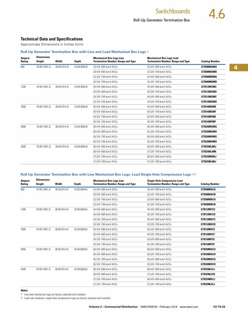
Technical Data and SpecificationsApproximate Dimensions in Inches (mm)
Roll-Up Generator Termination Box with Line and Load Mechanical Box Lugs 1
Roll-Up Generator Termination Box with Line Mechanical Box Lugs; Load Single-Hole Compression Lugs 12
Notes1 Line side mechanical lugs are factory selected and installed.2 Load side Anderson, single-hole compression lugs are factory selected and installed.
Ampere Rating
Dimensions Mechanical Box Lugs LineTermination Number, Range and Type
Mechanical Box Lugs LoadTermination Number, Range and Type Catalog NumberHeight Width Depth
800 78.00 (1981.2) 36.00 (914.4) 24.00 (609.6) (3) 4/0–500 kcmil Al/Cu (3) 4/0–500 kcmil Al/Cu GTB08MAMA
(3) 4/0–500 kcmil Al/Cu (2) 3/0–750 kcmil Al/Cu GTB08MAMB
(2) 3/0–750 kcmil Al/Cu (3) 4/0–500 kcmil Al/Cu GTB08MBMA
(2) 3/0–750 kcmil Al/Cu (2) 3/0–750 kcmil Al/Cu GTB08MBMB
1200 78.00 (1981.2) 36.00 (914.4) 24.00 (609.6) (4) 4/0–500 kcmil Al/Cu (4) 4/0–500 kcmil Al/Cu GTB12MCMC
(4) 4/0–500 kcmil Al/Cu (3) 3/0–750 kcmil Al/Cu GTB12MCMD
(3) 3/0–750 kcmil Al/Cu (4) 4/0–500 kcmil Al/Cu GTB12MDMC
(3) 3/0–750 kcmil Al/Cu (3) 3/0–750 kcmil Al/Cu GTB12MDMD
1600 78.00 (1981.2) 36.00 (914.4) 24.00 (609.6) (5) 4/0–500 kcmil Al/Cu (5) 4/0–500 kcmil Al/Cu GTB16MEME
(5) 4/0–500 kcmil Al/Cu (4) 3/0–750 kcmil Al/Cu GTB16MEMF
(4) 3/0–750 kcmil Al/Cu (5) 4/0–500 kcmil Al/Cu GTB16MFME
(4) 3/0–750 kcmil Al/Cu (4) 3/0–750 kcmil Al/Cu GTB16MFMF
2000 78.00 (1981.2) 36.00 (914.4) 24.00 (609.6) (6) 4/0–500 kcmil Al/Cu (6) 4/0–500 kcmil Al/Cu GTB20MGMG
(6) 4/0–500 kcmil Al/Cu (5) 3/0–750 kcmil Al/Cu GTB20MGMH
(5) 3/0–750 kcmil Al/Cu (6) 4/0–500 kcmil Al/Cu GTB20MHMG
(5) 3/0–750 kcmil Al/Cu (5) 3/0–750 kcmil Al/Cu GTB20MHMH
2500 78.00 (1981.2) 36.00 (914.4) 24.00 (609.6) (8) 4/0–500 kcmil Al/Cu (8) 4/0–500 kcmil Al/Cu GTB25MJMJ
(8) 4/0–500 kcmil Al/Cu (7) 3/0–750 kcmil Al/Cu GTB25MJMK
(7) 3/0–750 kcmil Al/Cu (8) 4/0–500 kcmil Al/Cu GTB25MKMJ
(7) 3/0–750 kcmil Al/Cu (7) 3/0–750 kcmil Al/Cu GTB25MJMJ
Ampere Rating
Dimensions Mechanical Box Lugs LineTermination Number, Range and Type
Single-Hole Compression LoadTermination Number, Range and Type Catalog NumberHeight Width Depth
800 78.00 (1981.2) 36.00 (914.4) 24.00 (609.6) (3) 4/0–500 kcmil Al/Cu (3) 4/0–500 kcmil Al/Cu GTB08MACA
(3) 4/0–500 kcmil Al/Cu (2) 3/0–750 kcmil Al/Cu GTB08MACB
(2) 3/0–750 kcmil Al/Cu (3) 4/0–500 kcmil Al/Cu GTB08MBCA
(2) 3/0–750 kcmil Al/Cu (2) 3/0–750 kcmil Al/Cu GTB08MBCB
1200 78.00 (1981.2) 36.00 (914.4) 24.00 (609.6) (4) 4/0–500 kcmil Al/Cu (4) 4/0–500 kcmil Al/Cu GTB12MCCC
(4) 4/0–500 kcmil Al/Cu (3) 3/0–750 kcmil Al/Cu GTB12MCCD
(3) 3/0–750 kcmil Al/Cu (4) 4/0–500 kcmil Al/Cu GTB12MDCC
(3) 3/0–750 kcmil Al/Cu (3) 3/0–750 kcmil Al/Cu GTB12MDCD
1600 78.00 (1981.2) 36.00 (914.4) 24.00 (609.6) (5) 4/0–500 kcmil Al/Cu (5) 4/0–500 kcmil Al/Cu GTB16MECE
(5) 4/0–500 kcmil Al/Cu (4) 3/0–750 kcmil Al/Cu GTB16MECF
(4) 3/0–750 kcmil Al/Cu (5) 4/0–500 kcmil Al/Cu GTB16MFCE
(4) 3/0–750 kcmil Al/Cu (4) 3/0–750 kcmil Al/Cu GTB16MFCF
2000 78.00 (1981.2) 36.00 (914.4) 24.00 (609.6) (6) 4/0–500 kcmil Al/Cu (6) 4/0–500 kcmil Al/Cu GTB20MGCG
(6) 4/0–500 kcmil Al/Cu (5) 3/0–750 kcmil Al/Cu GTB20MGCH
(5) 3/0–750 kcmil Al/Cu (6) 4/0–500 kcmil Al/Cu GTB20MHCG
(5) 3/0–750 kcmil Al/Cu (5) 3/0–750 kcmil Al/Cu GTB20MHCH
2500 78.00 (1981.2) 36.00 (914.4) 24.00 (609.6) (8) 4/0–500 kcmil Al/Cu (8) 4/0–500 kcmil Al/Cu GTB25MJCJ
(8) 4/0–500 kcmil Al/Cu (7) 3/0–750 kcmil Al/Cu GTB25MJCK
(7) 3/0–750 kcmil Al/Cu (8) 4/0–500 kcmil Al/Cu GTB25MKCJ
(7) 3/0–750 kcmil Al/Cu (7) 3/0–750 kcmil Al/Cu GTB25MJCJ

V2-T4-24 Volume 2—Commercial Distribution CA08100003E—February 2018 www.eaton.com
4
4
4
4
4
4
4
4
4
4
4
4
4
4
4
4
4
4
4
4
4
4
4
4
4
4
4
4
4
4
4.6 Switchboards
Roll-Up Generator Termination Box
Approximate Dimensions in Inches (mm)
Roll-Up Generator Termination Box with Line Mechanical Box Lugs; Load Two-Hole Compression Lugs 12
Notes1 Line side mechanical lugs are factory selected and installed.2 Load side factory installed Burndy, two-hole, short barrel compression lugs suitable for copper wire only requires a 45-inch (1143.0 mm) wide enclosure.
Ampere Rating
Dimensions Mechanical Box Lugs LineTermination Number, Range and Type
Two-Hole Compression LoadTermination Cu Only Wire Size Catalog NumberHeight Width Depth
800 78.00 (1981.2) 45.00 (1143.0) 24.00 (609.6) (3) 4/0–500 kcmil Al/Cu (3) 350 kcmil Cu only GTB08MACL
(3) 4/0–500 kcmil Al/Cu (3) 400 kcmil Cu only GTB08MBCM
(2) 3/0–750 kcmil Al/Cu (3) 350 kcmil Cu only GTB08MBCL
(2) 3/0–750 kcmil Al/Cu (3) 400 kcmil Cu only GTB08MACL
1200 78.00 (1981.2) 45.00 (1143.0) 24.00 (609.6) (4) 4/0–500 kcmil Al/Cu (4) 500 kcmil Cu only GTB12MCCN
(4) 4/0–500 kcmil Al/Cu (3) 600 kcmil Cu only GTB12MCCP
(4) 4/0–500 kcmil Al/Cu (3) 750 kcmil Cu only GTB12MCCQ
(3) 3/0–750 kcmil Al/Cu (4) 500 kcmil Cu only GTB12MDCN
(3) 3/0–750 kcmil Al/Cu (3) 600 kcmil Cu only GTB12MDCP
(3) 3/0–750 kcmil Al/Cu (3) 750 kcmil Cu only GTB12MDCQ
1600 78.00 (1981.2) 45.00 (1143.0) 24.00 (609.6) (5) 4/0–500 kcmil Al/Cu (5) 500 kcmil Cu only GTB16MECR
(5) 4/0–500 kcmil Al/Cu (4) 600 kcmil Cu only GTB16MECS
(5) 4/0–500 kcmil Al/Cu (4) 750 kcmil Cu only GTB16MECT
(4) 3/0–750 kcmil Al/Cu (5) 500 kcmil Cu only GTB16MFCR
(4) 3/0–750 kcmil Al/Cu (4) 600 kcmil Cu only GTB16MFCS
(4) 3/0–750 kcmil Al/Cu (4) 750 kcmil Cu only GTB16MFCT
2000 78.00 (1981.2) 45.00 (1143.0) 24.00 (609.6) (6) 4/0–500 kcmil Al/Cu (6) 500 kcmil Cu only GTB20MGCU
(6) 4/0–500 kcmil Al/Cu (5) 600 kcmil Cu only GTB20MGCV
(6) 4/0–500 kcmil Al/Cu (5) 750 kcmil Cu only GTB20MGCW
(5) 3/0–750 kcmil Al/Cu (6) 500 kcmil Cu only GTB20MHCU
(5) 3/0–750 kcmil Al/Cu (5) 600 kcmil Cu only GTB20MHCV
(5) 3/0–750 kcmil Al/Cu (5) 750 kcmil Cu only GTB20MHCW
2500 78.00 (1981.2) 45.00 (1143.0) 24.00 (609.6) (8) 4/0–500 kcmil Al/Cu (7) 500 kcmil Cu only GTB25MJCX
(8) 4/0–500 kcmil Al/Cu (6) 600 kcmil Cu only GTB25MJCY
(8) 4/0–500 kcmil Al/Cu (6) 750 kcmil Cu only GTB25MJCZ
(7) 3/0–750 kcmil Al/Cu (7) 500 kcmil Cu only GTB25MKCX
(7) 3/0–750 kcmil Al/Cu (6) 600 kcmil Cu only GTB25MKCY
(7) 3/0–750 kcmil Al/Cu (6) 750 kcmil Cu only GTB25MKCZ

Volume 2—Commercial Distribution CA08100003E—February 2018 www.eaton.com V2-T4-25
4
4
4
4
4
4
4
4
4
4
4
4
4
4
4
4
4
4
4
4
4
4
4
4
4
4
4
4
4
4
4.6Switchboards
Roll-Up Generator Termination Box
Approximate Dimensions in Inches (mm)
Roll-Up Generator Termination Box with Line Mechanical Box Lugs; Load Provisions Only, Single-Hole Compression Lugs 12
Roll-Up Generator Termination Box with Line Mechanical Box Lugs; Load Provisions Only, Two-Hole Compression Lugs 134
Notes1 Line side mechanical lugs are factory selected and installed.2 Load side factory installed 3/8-inch bolt provisions for single-hole compression lugs (lugs furnished by others).3 Load side factory installed 1/2-inch bolt provisions on 1-3/4-inch hole centers for two-hole compression lugs (lugs furnished by others). 4 Requires 45-inch (1143.0 mm) wide enclosure.
Ampere Rating
Dimensions Mechanical Box Lugs LineTermination Number, Range and Type
Single-Hole Compression LoadProvisions Only Number and Range Catalog NumberHeight Width Depth
800 78.00 (1981.2) 36.00 (914.4) 24.00 (609.6) (3) 4/0–500 kcmil Al/Cu (3) Provisions per phase GTB08MAP1
(2) 3/0–750 kcmil Al/Cu (3) Provisions per phase GTB08MBP1
1200 78.00 (1981.2) 36.00 (914.4) 24.00 (609.6) (4) 4/0–500 kcmil Al/Cu (4) Provisions per phase GTB12MCP2
(3) 3/0–750 kcmil Al/Cu (4) Provisions per phase GTB12MDP2
1600 78.00 (1981.2) 36.00 (914.4) 24.00 (609.6) (5) 4/0–500 kcmil Al/Cu (5) Provisions per phase GTB16MEP3
(4) 3/0–750 kcmil Al/Cu (5) Provisions per phase GTB16MFP3
2000 78.00 (1981.2) 36.00 (914.4) 24.00 (609.6) (6) 4/0–500 kcmil Al/Cu (6) Provisions per phase GTB20MGP4
(5) 3/0–750 kcmil Al/Cu (6) Provisions per phase GTB20MHP4
2500 78.00 (1981.2) 36.00 (914.4) 24.00 (609.6) (8) 4/0–500 kcmil Al/Cu (8) Provisions per phase GTB25MJP5
(7) 3/0–750 kcmil Al/Cu (8) Provisions per phase GTB25MKP5
Ampere Rating
Dimensions Mechanical Box Lugs LineTermination Number, Range and Type
Two-Hole Compression LoadProvisions Only Number and Range Catalog NumberHeight Width Depth
800 78.00 (1981.2) 45.00 (1143.0) 24.00 (609.6) (3) 4/0–500 kcmil Al/Cu (3) Provisions per phase GTB08MAPA
(2) 3/0–750 kcmil Al/Cu (3) Provisions per phase GTB08MBPA
1200 78.00 (1981.2) 45.00 (1143.0) 24.00 (609.6) (4) 4/0–500 kcmil Al/Cu (4) Provisions per phase GTB12MCPB
(3) 3/0–750 kcmil Al/Cu (4) Provisions per phase GTB12MDPB
1600 78.00 (1981.2) 45.00 (1143.0) 24.00 (609.6) (5) 4/0–500 kcmil Al/Cu (5) Provisions per phase GTB16MEPC
(4) 3/0–750 kcmil Al/Cu (5) Provisions per phase GTB16MFPC
2000 78.00 (1981.2) 45.00 (1143.0) 24.00 (609.6) (6) 4/0–500 kcmil Al/Cu (6) Provisions per phase GTB20MGPD
(5) 3/0–750 kcmil Al/Cu (6) Provisions per phase GTB20MHPD
2500 78.00 (1981.2) 45.00 (1143.0) 24.00 (609.6) (8) 4/0–500 kcmil Al/Cu (8) Provisions per phase GTB25MJPE
(7) 3/0–750 kcmil Al/Cu (8) Provisions per phase GTB25MKPE

V2-T4-26 Volume 2—Commercial Distribution CA08100003E—February 2018 www.eaton.com
4
4
4
4
4
4
4
4
4
4
4
4
4
4
4
4
4
4
4
4
4
4
4
4
4
4
4
4
4
4
4.6 Switchboards
Roll-Up Generator Termination Box
Approximate Dimensions in Inches (mm)
Roll-Up Generator Termination Box with Line Single-Hole Compression Lugs and Load Mechanical Box Lugs 12
Roll-Up Generator Termination Box with Line and Load Single-Hole Compression Lugs 3
Notes1 Line side Anderson, single-hole compression lugs are factory selected and installed.2 Load side mechanical lugs are factory selected and installed.3 Line side and load Anderson, single-hole compression lugs are factory selected and installed.
Ampere Rating
Dimensions Single-Hole Compression LineTermination Number, Range and Type
Mechanical Box Lugs LoadTermination Number, Range and Type Catalog NumberHeight Width Depth
800 78.00 (1981.2) 36.00 (914.4) 24.00 (609.6) (3) 4/0–500 kcmil Al/Cu (3) 4/0–500 kcmil Al/Cu GTB08CAMA
(3) 4/0–500 kcmil Al/Cu (2) 3/0–750 kcmil Al/Cu GTB08CAMB
(2) 3/0–750 kcmil Al/Cu (3) 4/0–500 kcmil Al/Cu GTB08CBMA
(2) 3/0–750 kcmil Al/Cu (2) 3/0–750 kcmil Al/Cu GTB08CBMB
1200 78.00 (1981.2) 36.00 (914.4) 24.00 (609.6) (4) 4/0–500 kcmil Al/Cu (4) 4/0–500 kcmil Al/Cu GTB12CCMC
(4) 4/0–500 kcmil Al/Cu (3) 3/0–750 kcmil Al/Cu GTB12CCMD
(3) 3/0–750 kcmil Al/Cu (4) 4/0–500 kcmil Al/Cu GTB12CDMC
(3) 3/0–750 kcmil Al/Cu (3) 3/0–750 kcmil Al/Cu GTB12CDMD
1600 78.00 (1981.2) 36.00 (914.4) 24.00 (609.6) (5) 4/0–500 kcmil Al/Cu (5) 4/0–500 kcmil Al/Cu GTB16CEME
(5) 4/0–500 kcmil Al/Cu (4) 3/0–750 kcmil Al/Cu GTB16CEMF
(4) 3/0–750 kcmil Al/Cu (5) 4/0–500 kcmil Al/Cu GTB16CFME
(4) 3/0–750 kcmil Al/Cu (4) 3/0–750 kcmil Al/Cu GTB16CFMF
2000 78.00 (1981.2) 36.00 (914.4) 24.00 (609.6) (6) 4/0–500 kcmil Al/Cu (6) 4/0–500 kcmil Al/Cu GTB20CGMG
(6) 4/0–500 kcmil Al/Cu (5) 3/0–750 kcmil Al/Cu GTB20CGMH
(5) 3/0–750 kcmil Al/Cu (6) 4/0–500 kcmil Al/Cu GTB20CHMG
(5) 3/0–750 kcmil Al/Cu (5) 3/0–750 kcmil Al/Cu GTB20CHMH
2500 78.00 (1981.2) 36.00 (914.4) 24.00 (609.6) (8) 4/0–500 kcmil Al/Cu (8) 4/0–500 kcmil Al/Cu GTB25CJMJ
(8) 4/0–500 kcmil Al/Cu (7) 3/0–750 kcmil Al/Cu GTB25CJMK
(7) 3/0–750 kcmil Al/Cu (8) 4/0–500 kcmil Al/Cu GTB25CKMJ
(7) 3/0–750 kcmil Al/Cu (7) 3/0–750 kcmil Al/Cu GTB25CJMK
Ampere Rating
Dimensions Single-Hole Compression LineTermination Number, Range and Type
Single-Hole Compression LoadTermination Number, Range and Type Catalog NumberHeight Width Depth
800 78.00 (1981.2) 36.00 (914.4) 24.00 (609.6) (3) 4/0–500 kcmil Al/Cu (3) 4/0–500 kcmil Al/Cu GTB08CACA
(3) 4/0–500 kcmil Al/Cu (2) 3/0–750 kcmil Al/Cu GTB08CACB
(2) 3/0–750 kcmil Al/Cu (3) 4/0–500 kcmil Al/Cu GTB08CBCA
(2) 3/0–750 kcmil Al/Cu (2) 3/0–750 kcmil Al/Cu GTB08CBCB
1200 78.00 (1981.2) 36.00 (914.4) 24.00 (609.6) (4) 4/0–500 kcmil Al/Cu (4) 4/0–500 kcmil Al/Cu GTB12CCCC
(4) 4/0–500 kcmil Al/Cu (3) 3/0–750 kcmil Al/Cu GTB12CCCD
(3) 3/0–750 kcmil Al/Cu (4) 4/0–500 kcmil Al/Cu GTB12CDCC
(3) 3/0–750 kcmil Al/Cu (3) 3/0–750 kcmil Al/Cu GTB12CDCD
1600 78.00 (1981.2) 36.00 (914.4) 24.00 (609.6) (5) 4/0–500 kcmil Al/Cu (5) 4/0–500 kcmil Al/Cu GTB16CECE
(5) 4/0–500 kcmil Al/Cu (4) 3/0–750 kcmil Al/Cu GTB16CECF
(4) 3/0–750 kcmil Al/Cu (5) 4/0–500 kcmil Al/Cu GTB16CFCE
(4) 3/0–750 kcmil Al/Cu (4) 3/0–750 kcmil Al/Cu GTB16CFCF
2000 78.00 (1981.2) 36.00 (914.4) 24.00 (609.6) (6) 4/0–500 kcmil Al/Cu (6) 4/0–500 kcmil Al/Cu GTB20CGCG
(6) 4/0–500 kcmil Al/Cu (5) 3/0–750 kcmil Al/Cu GTB20CGCH
(5) 3/0–750 kcmil Al/Cu (6) 4/0–500 kcmil Al/Cu GTB20CHCG
(5) 3/0–750 kcmil Al/Cu (5) 3/0–750 kcmil Al/Cu GTB20CHCH
2500 78.00 (1981.2) 36.00 (914.4) 24.00 (609.6) (8) 4/0–500 kcmil Al/Cu (8) 4/0–500 kcmil Al/Cu GTB25CJCJ
(8) 4/0–500 kcmil Al/Cu (7) 3/0–750 kcmil Al/Cu GTB25CJCK
(7) 3/0–750 kcmil Al/Cu (8) 4/0–500 kcmil Al/Cu GTB25CKCJ
(7) 3/0–750 kcmil Al/Cu (7) 3/0–750 kcmil Al/Cu GTB25CJCK

Volume 2—Commercial Distribution CA08100003E—February 2018 www.eaton.com V2-T4-27
4
4
4
4
4
4
4
4
4
4
4
4
4
4
4
4
4
4
4
4
4
4
4
4
4
4
4
4
4
4
4.6Switchboards
Roll-Up Generator Termination Box
Approximate Dimensions in Inches (mm)
Roll-Up Generator Termination Box with Line Single-Hole Compression Lugs; Load Two-Hole Compression Lugs 123
Roll-Up Generator Termination Box with Line Single-Hole Compression Lugs; Load Provisions Only, Single-Hole Compression Lugs 14
Notes1 Line side Anderson, single-hole compression lugs are factory selected and installed.2 Load side factory installed Burndy, two-hole, short barrel compression lugs suitable for copper wire only.3 Requires 45-inch (1143.0 mm) wide enclosure.4 Load side factory installed 3/8-inch bolt provisions for single-hole compression lugs (lugs furnished by others).
Ampere Rating
Dimensions Single-Hole Compression LineTermination Number, Range and Type
Two-Hole Compression LoadTermination Cu Only Wire Size Catalog NumberHeight Width Depth
800 78.00 (1981.2) 45.00 (1143.0) 24.00 (609.6) (3) 4/0–500 kcmil Al/Cu (3) 350 kcmil Cu only GTB08CACL
(3) 4/0–500 kcmil Al/Cu (3) 400 kcmil Cu only GTB08CACM
(2) 3/0–750 kcmil Al/Cu (3) 350 kcmil Cu only GTB08CBCL
(2) 3/0–750 kcmil Al/Cu (3) 400 kcmil Cu only GTB08CBCM
1200 78.00 (1981.2) 45.00 (1143.0) 24.00 (609.6) (4) 4/0–500 kcmil Al/Cu (4) 500 kcmil Cu only GTB12CCCN
(4) 4/0–500 kcmil Al/Cu (3) 600 kcmil Cu only GTB12CCCP
(4) 4/0–500 kcmil Al/Cu (3) 750 kcmil Cu only GTB12CCCQ
(3) 3/0–750 kcmil Al/Cu (4) 500 kcmil Cu only GTB12CDCN
(3) 3/0–750 kcmil Al/Cu (3) 600 kcmil Cu only GTB12CDCP
(3) 3/0–750 kcmil Al/Cu (3) 750 kcmil Cu only GTB12CDCQ
1600 78.00 (1981.2) 45.00 (1143.0) 24.00 (609.6) (5) 4/0–500 kcmil Al/Cu (5) 500 kcmil Cu only GTB16CECR
(5) 4/0–500 kcmil Al/Cu (4) 600 kcmil Cu only GTB16CECS
(5) 4/0–500 kcmil Al/Cu (4) 750 kcmil Cu only GTB16CECT
(4) 3/0–750 kcmil Al/Cu (5) 500 kcmil Cu only GTB16CFCR
(4) 3/0–750 kcmil Al/Cu (4) 600 kcmil Cu only GTB16CFCS
(4) 3/0–750 kcmil Al/Cu (4) 750 kcmil Cu only GTB16CFCT
2000 78.00 (1981.2) 45.00 (1143.0) 24.00 (609.6) (6) 4/0–500 kcmil Al/Cu (6) 500 kcmil Cu only GTB20CGCU
(6) 4/0–500 kcmil Al/Cu (5) 600 kcmil Cu only GTB20CGCV
(6) 4/0–500 kcmil Al/Cu (5) 750 kcmil Cu only GTB20CGCW
(5) 3/0–750 kcmil Al/Cu (6) 500 kcmil Cu only GTB20CHCU
(5) 3/0–750 kcmil Al/Cu (5) 600 kcmil Cu only GTB20CHCV
(5) 3/0–750 kcmil Al/Cu (5) 750 kcmil Cu only GTB20CHCW
2500 78.00 (1981.2) 45.00 (1143.0) 24.00 (609.6) (8) 4/0–500 kcmil Al/Cu (7) 500 kcmil Cu only GTB25CJCX
(8) 4/0–500 kcmil Al/Cu (6) 600 kcmil Cu only GTB25CJCY
(8) 4/0–500 kcmil Al/Cu (6) 750 kcmil Cu only GTB25CJCZ
(7) 3/0–750 kcmil Al/Cu (7) 500 kcmil Cu only GTB25CKCX
(7) 3/0–750 kcmil Al/Cu (6) 600 kcmil Cu only GTB25CKCY
(7) 3/0–750 kcmil Al/Cu (6) 750 kcmil Cu only GTB25CKCZ
Ampere Rating
Dimensions Single-Hole Compression LineTermination Number, Range and Type
Single-Hole Compression LoadProvisions Only Number and Range Catalog NumberHeight Width Depth
800 78.00 (1981.2) 36.00 (914.4) 24.00 (609.6) (3) 4/0–500 kcmil Al/Cu (3) Provisions per phase GTB08CAP1
(2) 3/0–750 kcmil Al/Cu (3) Provisions per phase GTB08CBP1
1200 78.00 (1981.2) 36.00 (914.4) 24.00 (609.6) (4) 4/0–500 kcmil Al/Cu (4) Provisions per phase GTB12CCP2
(3) 3/0–750 kcmil Al/Cu (4) Provisions per phase GTB12CDP2
1600 78.00 (1981.2) 36.00 (914.4) 24.00 (609.6) (5) 4/0–500 kcmil Al/Cu (5) Provisions per phase GTB16CEP3
(4) 3/0–750 kcmil Al/Cu (5) Provisions per phase GTB16CFP3
2000 78.00 (1981.2) 36.00 (914.4) 24.00 (609.6) (6) 4/0–500 kcmil Al/Cu (6) Provisions per phase GTB20CGP4
(5) 3/0–750 kcmil Al/Cu (6) Provisions per phase GTB20CHP4
2500 78.00 (1981.2) 36.00 (914.4) 24.00 (609.6) (8) 4/0–500 kcmil Al/Cu (8) Provisions per phase GTB25CJP5
(7) 3/0–750 kcmil Al/Cu (8) Provisions per phase GTB25CKP5

V2-T4-28 Volume 2—Commercial Distribution CA08100003E—February 2018 www.eaton.com
4
4
4
4
4
4
4
4
4
4
4
4
4
4
4
4
4
4
4
4
4
4
4
4
4
4
4
4
4
4
4.6 Switchboards
Roll-Up Generator Termination Box
Approximate Dimensions in Inches (mm)
Roll-Up Generator Termination Box with Single-Hole Compression Lugs; Load Provisions Only, Two-Hole Compression Lugs) 123
Roll-Up Generator Termination Box with Line Two-Hole Compression Lugs and Load Mechanical Box Lugs 345
Notes1 Line side Anderson, single-hole compression lugs are factory selected and installed.2 Load side factory installed 1/2-inch bolt provisions on 1-3/4-inch hole centers for two-hole compression lugs (lugs furnished by others).3 Requires 45-inch (1143.0 mm) wide enclosure.4 Line side factory installed Burndy, two-hole, short barrel compression lugs suitable for copper wire only.5 Load side mechanical lugs are factory selected and installed.
Ampere Rating
Dimensions Single-Hole Compression LineTermination Number, Range and Type
Two-Hole Compression LoadProvisions Only Number and Range Catalog NumberHeight Width Depth
800 78.00 (1981.2) 45.00 (1143.0) 24.00 (609.6) (3) 4/0–500 kcmil Al/Cu (3) Provisions per phase GTB08CAPA
(2) 3/0–750 kcmil Al/Cu (3) Provisions per phase GTB08CBPA
1200 78.00 (1981.2) 45.00 (1143.0) 24.00 (609.6) (4) 4/0–500 kcmil Al/Cu (4) Provisions per phase GTB12CCPB
(3) 3/0–750 kcmil Al/Cu (4) Provisions per phase GTB12CDPB
1600 78.00 (1981.2) 45.00 (1143.0) 24.00 (609.6) (5) 4/0–500 kcmil Al/Cu (5) Provisions per phase GTB16CEPC
(4) 3/0–750 kcmil Al/Cu (5) Provisions per phase GTB16CGPC
2000 78.00 (1981.2) 45.00 (1143.0) 24.00 (609.6) (6) 4/0–500 kcmil Al/Cu (6) Provisions per phase GTB20CGPD
(5) 3/0–750 kcmil Al/Cu (6) Provisions per phase GTB20CHPD
2500 78.00 (1981.2) 45.00 (1143.0) 24.00 (609.6) (8) 4/0–500 kcmil Al/Cu (8) Provisions per phase GTB25CJPE
(7) 3/0–750 kcmil Al/Cu (8) Provisions per phase GTB25CKPE
AmpereRating
Dimensions Two-Hole Compression LineTermination Cu Only Wire Size
Mechanical Box Lugs LoadTermination Number, Range and Type Catalog NumberHeight Width Depth
800 78.00 (1981.2) 45.00 (1143.0) 24.00 (609.6) (3) 350 kcmil Cu only (3) 4/0–500 kcmil Al/Cu GTB08CLMA
(3) 350 kcmil Cu only (2) 3/0–750 kcmil Al/Cu GTB08CLMB
(3) 400 kcmil Cu only (3) 4/0–500 kcmil Al/Cu GTB08CMMA
(3) 400 kcmil Cu only (2) 3/0–750 kcmil Al/Cu GTB08CMMB
1200 78.00 (1981.2) 45.00 (1143.0) 24.00 (609.6) (4) 500 kcmil Cu only (4) 4/0–500 kcmil Al/Cu GTB12CNMC
(4) 500 kcmil Cu only (3) 3/0–750 kcmil Al/Cu GTB12CNMD
(3) 600 kcmil Cu only (4) 4/0–500 kcmil Al/Cu GTB12CPMC
(3) 600 kcmil Cu only (3) 3/0–750 kcmil Al/Cu GTB12CPMD
(3) 750 kcmil Cu only (4) 4/0–500 kcmil Al/Cu GTB12CQMC
(3) 750 kcmil Cu only (3) 3/0–750 kcmil Al/Cu GTB12CQMD
1600 78.00 (1981.2) 45.00 (1143.0) 24.00 (609.6) (5) 500 kcmil Cu only (5) 4/0–500 kcmil Al/Cu GTB16CRME
(5) 500 kcmil Cu only (4) 3/0–750 kcmil Al/Cu GTB16CRMF
(4) 600 kcmil Cu only (5) 4/0–500 kcmil Al/Cu GTB16CSME
(4) 600 kcmil Cu only (4) 3/0–750 kcmil Al/Cu GTB16CSMF
(4) 750 kcmil Cu only (5) 4/0–500 kcmil Al/Cu GTB16CTME
(4) 750 kcmil Cu only (4) 3/0–750 kcmil Al/Cu GTB16CTMF
2000 78.00 (1981.2) 45.00 (1143.0) 24.00 (609.6) (6) 500 kcmil Cu only (6) 4/0–500 kcmil Al/Cu GTB20CUMG
(6) 500 kcmil Cu only (5) 3/0–750 kcmil Al/Cu GTB20CUMH
(5) 600 kcmil Cu only (6) 4/0–500 kcmil Al/Cu GTB20CVMG
(5) 600 kcmil Cu only (5) 3/0–750 kcmil Al/Cu GTB20CVMH
(5) 750 kcmil Cu only (6) 4/0–500 kcmil Al/Cu GTB20CWMG
(5) 750 kcmil Cu only (5) 3/0–750 kcmil Al/Cu GTB20CWMH
2500 78.00 (1981.2) 45.00 (1143.0) 24.00 (609.6) (7) 500 kcmil Cu only (8) 4/0–500 kcmil Al/Cu GTB25CXMJ
(7) 500 kcmil Cu only (7) 3/0–750 kcmil Al/Cu GTB25CXMK
(6) 600 kcmil Cu only (8) 4/0–500 kcmil Al/Cu GTB25CYMJ
(6) 600 kcmil Cu only (7) 3/0–750 kcmil Al/Cu GTB25CYMK
(6) 750 kcmil Cu only (8) 4/0–500 kcmil Al/Cu GTB25CZMJ
(6) 750 kcmil Cu only (7) 3/0–750 kcmil Al/Cu GTB25CZMK

Volume 2—Commercial Distribution CA08100003E—February 2018 www.eaton.com V2-T4-29
4
4
4
4
4
4
4
4
4
4
4
4
4
4
4
4
4
4
4
4
4
4
4
4
4
4
4
4
4
4
4.6Switchboards
Roll-Up Generator Termination Box
Approximate Dimensions in Inches (mm)
Roll-Up Generator Termination Box with Line Two-Hole Compression Lugs and Load Single-Hole Compression Lugs
NotesLine side factory installed Burndy, two-hole, short barrel compression lugs suitable for copper wire only.Load side Anderson, single-hole compression lugs are factory selected and installed.Requires 45-inch (1143.0 mm) wide enclosure.
Ampere Rating
Dimensions Two-Hole Compression LineTermination Cu Only Wire Size
Single-Hole Compression LoadTermination Number, Range and Type Catalog NumberHeight Width Depth
800 78.00 (1981.2) 45.00 (1143.0) 24.00 (609.6) (3) 350 kcmil Cu only (3) 4/0–500 kcmil Al/Cu GTB08CLCA
(3) 350 kcmil Cu only (2) 3/0–750 kcmil Al/Cu GTB08CLCB
(3) 400 kcmil Cu only (3) 4/0–500 kcmil Al/Cu GTB08CMCA
(3) 400 kcmil Cu only (2) 3/0–750 kcmil Al/Cu GTB08CMCB
1200 78.00 (1981.2) 45.00 (1143.0) 24.00 (609.6) (4) 500 kcmil Cu only (4) 4/0–500 kcmil Al/Cu GTB12CNCC
(4) 500 kcmil Cu only (3) 3/0–750 kcmil Al/Cu GTB12CNCD
(3) 600 kcmil Cu only (4) 4/0–500 kcmil Al/Cu GTB12CPCC
(3) 600 kcmil Cu only (3) 3/0–750 kcmil Al/Cu GTB12CPCD
(3) 750 kcmil Cu only (4) 4/0–500 kcmil Al/Cu GTB12CQCC
(3) 750 kcmil Cu only (3) 3/0–750 kcmil Al/Cu GTB12CQCD
1600 78.00 (1981.2) 45.00 (1143.0) 24.00 (609.6) (5) 500 kcmil Cu only (5) 4/0–500 kcmil Al/Cu GTB16CRCE
(5) 500 kcmil Cu only (4) 3/0–750 kcmil Al/Cu GTB16CRCF
(4) 600 kcmil Cu only (5) 4/0–500 kcmil Al/Cu GTB16CSCE
(4) 600 kcmil Cu only (4) 3/0–750 kcmil Al/Cu GTB16CSCF
(4) 750 kcmil Cu only (5) 4/0–500 kcmil Al/Cu GTB16CTCE
(4) 750 kcmil Cu only (4) 3/0–750 kcmil Al/Cu GTB16CTCF
2000 78.00 (1981.2) 45.00 (1143.0) 24.00 (609.6) (6) 500 kcmil Cu only (6) 4/0–500 kcmil Al/Cu GTB20CUCG
(6) 500 kcmil Cu only (5) 3/0–750 kcmil Al/Cu GTB20CUCH
(5) 600 kcmil Cu only (6) 4/0–500 kcmil Al/Cu GTB20CVCG
(5) 600 kcmil Cu only (5) 3/0–750 kcmil Al/Cu GTB20CVCH
(5) 750 kcmil Cu only (6) 4/0–500 kcmil Al/Cu GTB20CWCG
(5) 750 kcmil Cu only (5) 3/0–750 kcmil Al/Cu GTB20CWCH
2500 78.00 (1981.2) 45.00 (1143.0) 24.00 (609.6) (7) 500 kcmil Cu only (8) 4/0–500 kcmil Al/Cu GTB25CXCJ
(7) 500 kcmil Cu only (7) 3/0–750 kcmil Al/Cu GTB25CXCK
(6) 600 kcmil Cu only (8) 4/0–500 kcmil Al/Cu GTB25CYCJ
(6) 600 kcmil Cu only (7) 3/0–750 kcmil Al/Cu GTB25CYCK
(6) 750 kcmil Cu only (8) 4/0–500 kcmil Al/Cu GTB25CZCJ
(6) 750 kcmil Cu only (7) 3/0–750 kcmil Al/Cu GTB25CZCK

V2-T4-30 Volume 2—Commercial Distribution CA08100003E—February 2018 www.eaton.com
4
4
4
4
4
4
4
4
4
4
4
4
4
4
4
4
4
4
4
4
4
4
4
4
4
4
4
4
4
4
4.6 Switchboards
Roll-Up Generator Termination Box
Approximate Dimensions in Inches (mm)
Roll-Up Generator Termination Box with Line Two-Hole Compression Lugs; Load Two-Hole Compression Lugs
NotesLine and load side factory installed Burndy, two-hole, short barrel compression lugs suitable for copper wire only.Requires 45-inch (1143.0 mm) wide enclosure.
Ampere Rating
Dimensions Two-Hole Compression LineTermination Cu Only Wire Size
Two-Hole Compression LoadTermination Cu Only Wire Size Catalog NumberHeight Width Depth
800 78.00 (1981.2) 45.00 (1143.0) 24.00 (609.6) (3) 350 kcmil Cu only (3) 350 kcmil Cu only GTB08CLCL
(3) 350 kcmil Cu only (3) 400 kcmil Cu only GTB08CLCM
(3) 400 kcmil Cu only (3) 350 kcmil Cu only GTB08CMCL
(3) 400 kcmil Cu only (3) 400 kcmil Cu only GTB08CMCM
1200 78.00 (1981.2) 45.00 (1143.0) 24.00 (609.6) (4) 500 kcmil Cu only (4) 500 kcmil Cu only GTB12CNCN
(4) 500 kcmil Cu only (3) 600 kcmil Cu only GTB12CNCP
(4) 500 kcmil Cu only (3) 750 kcmil Cu only GTB12CNCQ
(3) 600 kcmil Cu only (4) 500 kcmil Cu only GTB12CPCN
(3) 600 kcmil Cu only (3) 600 kcmil Cu only GTB12CPCP
(3) 600 kcmil Cu only (3) 750 kcmil Cu only GTB12CPCQ
(3) 750 kcmil Cu only (4) 500 kcmil Cu only GTB12CQCN
(3) 750 kcmil Cu only (3) 600 kcmil Cu only GTB12CQCP
(3) 750 kcmil Cu only (3) 750 kcmil Cu only GTB12CQCQ
1600 78.00 (1981.2) 45.00 (1143.0) 24.00 (609.6) (5) 500 kcmil Cu only (5) 500 kcmil Cu only GTB16CRCR
(5) 500 kcmil Cu only (4) 600 kcmil Cu only GTB16CRCS
(5) 500 kcmil Cu only (4) 750 kcmil Cu only GTB16CRCT
(4) 600 kcmil Cu only (5) 500 kcmil Cu only GTB16CSCR
(4) 600 kcmil Cu only (4) 600 kcmil Cu only GTB16CSCS
(4) 600 kcmil Cu only (4) 750 kcmil Cu only GTB16CSCT
(4) 750 kcmil Cu only (5) 500 kcmil Cu only GTB16CTCR
(4) 750 kcmil Cu only (4) 600 kcmil Cu only GTB16CTCS
(4) 750 kcmil Cu only (4) 750 kcmil Cu only GTB16CTCT
2000 78.00 (1981.2) 45.00 (1143.0) 24.00 (609.6) (6) 500 kcmil Cu only (6) 500 kcmil Cu only GTB20CUCU
(6) 500 kcmil Cu only (5) 600 kcmil Cu only GTB20CUCV
(6) 500 kcmil Cu only (5) 750 kcmil Cu only GTB20CUCW
(5) 600 kcmil Cu only (6) 500 kcmil Cu only GTB20CVCU
(5) 600 kcmil Cu only (5) 600 kcmil Cu only GTB20CVCU
(5) 600 kcmil Cu only (5) 750 kcmil Cu only GTB20CVCW
(5) 750 kcmil Cu only (6) 500 kcmil Cu only GTB20CWCU
(5) 750 kcmil Cu only (5) 600 kcmil Cu only GTB20CWCV
(5) 750 kcmil Cu only (5) 750 kcmil Cu only GTB20CWCW
2500 78.00 (1981.2) 45.00 (1143.0) 24.00 (609.6) (7) 500 kcmil Cu only (7) 500 kcmil Cu only GTB25CXCX
(7) 500 kcmil Cu only (6) 600 kcmil Cu only GTB25CXCY
(7) 500 kcmil Cu only (6) 750 kcmil Cu only GTB25CXCZ
(6) 600 kcmil Cu only (7) 500 kcmil Cu only GTB25CYCX
(6) 600 kcmil Cu only (6) 600 kcmil Cu only GTB25CYCY
(6) 600 kcmil Cu only (6) 750 kcmil Cu only GTB25CYCZ
(6) 750 kcmil Cu only (7) 500 kcmil Cu only GTB25CZCX
(6) 750 kcmil Cu only (6) 600 kcmil Cu only GTB25CZCY
(6) 750 kcmil Cu only (6) 750 kcmil Cu only GTB25CZCZ

Volume 2—Commercial Distribution CA08100003E—February 2018 www.eaton.com V2-T4-31
4
4
4
4
4
4
4
4
4
4
4
4
4
4
4
4
4
4
4
4
4
4
4
4
4
4
4
4
4
4
4.6Switchboards
Roll-Up Generator Termination Box
Approximate Dimensions in Inches (mm)
Roll-Up Generator Termination Box with Line Two-Hole Compression Lugs; Load Provisions Only, Single-Hole Compression Lugs 123
Roll-Up Generator Termination Box with Two-Hole Compression Lugs; Load Provisions Only, Two-Hole Compression Lugs 4
Notes1 Line side factory installed Burndy, two-hole, short barrel compression lugs suitable for copper wire only.2 Load side factory installed 3/8-inch bolt provisions for single-hole compression lugs (lugs furnished by others).3 Requires 45-inch (1143.0 mm) wide enclosure.4 Load side factory installed 1/2-inch bolt provisions on 1-3/4-inch hole centers for two-hole compression lugs (lugs furnished by others).
Ampere Rating
Dimensions Two-Hole Compression Line Termination Cu Only Wire Size
Single-Hole Compression Load ProvisionsOnly Number and Range Catalog NumberHeight Width Depth
800 78.00 (1981.2) 45.00 (1143.0) 24.00 (609.6) (3) 350 kcmil Cu only (3) Provisions per phase GTB08CLP1
(3) 400 kcmil Cu only (3) Provisions per phase GTB08CMP1
1200 78.00 (1981.2) 45.00 (1143.0) 24.00 (609.6) (4) 500 kcmil Cu only (4) Provisions per phase GTB12CNP2
(3) 600 kcmil Cu only (4) Provisions per phase GTB12CPP2
(3) 750 kcmil Cu only (4) Provisions per phase GTB12CQP2
2000 78.00 (1981.2) 45.00 (1143.0) 24.00 (609.6) (6) 500 kcmil Cu only (6) Provisions per phase GTB20CUP4
(5) 600 kcmil Cu only (6) Provisions per phase GTB20CVP4
(5) 750 kcmil Cu only (6) Provisions per phase GTB20CWP4
2500 78.00 (1981.2) 45.00 (1143.0) 24.00 (609.6) (7) 500 kcmil Cu only (8) Provisions per phase GTB25CXP5
(6) 600 kcmil Cu only (8) Provisions per phase GTB25CYP6
(6) 750 kcmil Cu only (8) Provisions per phase GTB25CZP6
Ampere Rating
Dimensions Two-Hole Compression Line Termination Cu Only Wire Size
Two-Hole Compression Load ProvisionsOnly Number and Range Catalog NumberHeight Width Depth
800 78.00 (1981.2) 45.00 (1143.0) 24.00 (609.6) (3) 350 kcmil Cu only (3) Provisions per phase GTB08CLPA
(3) 400 kcmil Cu only (3) Provisions per phase GTB08CMPA
1200 78.00 (1981.2) 45.00 (1143.0) 24.00 (609.6) (4) 500 kcmil Cu only (4) Provisions per phase GTB12CNPB
(3) 600 kcmil Cu only (4) Provisions per phase GTB12CPPB
(3) 750 kcmil Cu only (4) Provisions per phase GTB12CQPB
1600 78.00 (1981.2) 45.00 (1143.0) 24.00 (609.6) (5) 500 kcmil Cu only (5) Provisions per phase GTB16CRPC
(4) 600 kcmil Cu only (5) Provisions per phase GTB16CSPC
(4) 750 kcmil Cu only (5) Provisions per phase GTB16CTPC
2000 78.00 (1981.2) 45.00 (1143.0) 24.00 (609.6) (6) 500 kcmil Cu only (6) Provisions per phase GTB20CUPD
(5) 600 kcmil Cu only (6) Provisions per phase GTB20CVPD
(5) 750 kcmil Cu only (6) Provisions per phase GTB20CWPD
2500 78.00 (1981.2) 45.00 (1143.0) 24.00 (609.6) (7) 500 kcmil Cu only (8) Provisions per phase GTB25CXPE
(6) 600 kcmil Cu only (8) Provisions per phase GTB25CYPE
(6) 750 kcmil Cu only (8) Provisions per phase GTB25CZPE

V2-T4-32 Volume 2—Commercial Distribution CA08100003E—February 2018 www.eaton.com
4
4
4
4
4
4
4
4
4
4
4
4
4
4
4
4
4
4
4
4
4
4
4
4
4
4
4
4
4
4
4.6 Switchboards
Roll-Up Generator Termination Box
Approximate Dimensions in Inches (mm)
Roll-Up Generator Termination Box with Line Single-Hole Compression Lug Provisions; Load Mechanical Box Lugs 12
Roll-Up Generator Termination Box with Line Single-Hole Compression Lug Provisions; Load Single-Hole Compression Lugs 13
Notes1 Line side factory installed 3/8-inch bolt provisions for single-hole compression lugs (lugs furnished by others).2 Load side mechanical lugs are factory selected and installed.3 Load side Anderson, single-hole compression lugs are factory selected and installed.
Ampere Rating
Dimensions Single-Hole Compression Line ProvisionsOnly Number and Range
Mechanical Box Lugs LoadTermination Number, Range and Type Catalog NumberHeight Width Depth
800 78.00 (1981.2) 36.00 (914.4) 24.00 (609.6) (3) Provisions per phase (3) 4/0–500 kcmil Al/Cu GTB08P1MA
(3) Provisions per phase (2) 3/0–750 kcmil Al/Cu GTB08P1MB
1200 78.00 (1981.2) 36.00 (914.4) 24.00 (609.6) (4) Provisions per phase (4) 4/0–500 kcmil Al/Cu GTB12P2MC
(4) Provisions per phase (3) 3/0–750 kcmil Al/Cu GTB12P2MD
1600 78.00 (1981.2) 36.00 (914.4) 24.00 (609.6) (5) Provisions per phase (5) 4/0–500 kcmil Al/Cu GTB16P3ME
(5) Provisions per phase (4) 3/0–750 kcmil Al/Cu GTB16P3MF
2000 78.00 (1981.2) 36.00 (914.4) 24.00 (609.6) (6) Provisions per phase (6) 4/0–500 kcmil Al/Cu GTB20P4MG
(6) Provisions per phase (5) 3/0–750 kcmil Al/Cu GTB20P4MH
2500 78.00 (1981.2) 36.00 (914.4) 24.00 (609.6) (8) Provisions per phase (8) 4/0–500 kcmil Al/Cu GTB25P5MJ
(8) Provisions per phase (7) 3/0–750 kcmil Al/Cu GTB25P5MK
Ampere Rating
Dimensions Single-Hole Compression Line ProvisionsOnly Number and Range
Single-Hole Compression Load TerminationNumber, Range and Type Catalog NumberHeight Width Depth
800 78.00 (1981.2) 36.00 (914.4) 24.00 (609.6) (3) Provisions per phase (3) 4/0–500 kcmil Al/Cu GTB08P1CA
(3) Provisions per phase (2) 3/0–750 kcmil Al/Cu GTB08P1CB
1200 78.00 (1981.2) 36.00 (914.4) 24.00 (609.6) (4) Provisions per phase (4) 4/0–500 kcmil Al/Cu GTB12P2CC
(4) Provisions per phase (3) 3/0–750 kcmil Al/Cu GTB12P2CD
1600 78.00 (1981.2) 36.00 (914.4) 24.00 (609.6) (5) Provisions per phase (5) 4/0–500 kcmil Al/Cu GTB16P3CE
(5) Provisions per phase (4) 3/0–750 kcmil Al/Cu GTB16P3CF
2000 78.00 (1981.2) 36.00 (914.4) 24.00 (609.6) (6) Provisions per phase (6) 4/0–500 kcmil Al/Cu GTB20P4CG
(6) Provisions per phase (5) 3/0–750 kcmil Al/Cu GTB20P4CH
2500 78.00 (1981.2) 36.00 (914.4) 24.00 (609.6) (8) Provisions per phase (8) 4/0–500 kcmil Al/Cu GTB25P5CJ
(8) Provisions per phase (7) 3/0–750 kcmil Al/Cu GTB25P5CK

Volume 2—Commercial Distribution CA08100003E—February 2018 www.eaton.com V2-T4-33
4
4
4
4
4
4
4
4
4
4
4
4
4
4
4
4
4
4
4
4
4
4
4
4
4
4
4
4
4
4
4.6Switchboards
Roll-Up Generator Termination Box
Approximate Dimensions in Inches (mm)
Roll-Up Generator Termination Box with Line Single-Hole Compression Lug Provisions; Load Two-Hole Compression Lugs 123
Roll-Up Generator Termination Box with Line Single-Hole Compression Lug Provisions; Load Single-Hole Compression Lugs 4
Notes1 Line side factory installed 3/8-inch bolt provisions for single-hole compression lugs (lugs furnished by others).2 Load side factory installed Burndy, two-hole, short barrel compression lugs suitable for copper wire only.3 Requires 45-inch (1143.0 mm) wide enclosure.4 Line and load side factory installed 3/8-inch bolt provisions for single-hole compression lugs (lugs furnished by others).
AmpereRating
Dimensions Single-Hole Compression Line ProvisionsOnly Number and Range
Two-Hole Compression Load TerminationCu Only Wire Size Catalog NumberHeight Width Depth
800 78.00 (1981.2) 45.00 (1143.0) 24.00 (609.6) (3) 4/0–500 kcmil (3) 350 kcmil Cu only GTB08P1CL
(3) 4/0–500 kcmil (3) 400 kcmil Cu only GTB08P1CM
1200 78.00 (1981.2) 45.00 (1143.0) 24.00 (609.6) (4) 4/0–500 kcmil (4) 500 kcmil Cu only GTB12P2CN
(4) 4/0–500 kcmil (3) 600 kcmil Cu only GTB12P2CP
(4) 4/0–500 kcmil (3) 750 kcmil Cu only GTB12P2CQ
1600 78.00 (1981.2) 45.00 (1143.0) 24.00 (609.6) (5) 4/0–500 kcmil (5) 500 kcmil Cu only GTB16P3CR
(5) 4/0–500 kcmil (4) 600 kcmil Cu only GTB16P3CS
(5) 4/0–500 kcmil (4) 750 kcmil Cu only GTB16P3CT
2000 78.00 (1981.2) 45.00 (1143.0) 24.00 (609.6) (6) 4/0–500 kcmil (6) 500 kcmil Cu only GTB20P4CU
(6) 4/0–500 kcmil (5) 600 kcmil Cu only GTB20P4CU
(6) 4/0–500 kcmil (5) 750 kcmil Cu only GTB20P4CW
2500 78.00 (1981.2) 45.00 (1143.0) 24.00 (609.6) (8) 4/0–500 kcmil (7) 500 kcmil Cu only GTB25P5CX
(8) 4/0–500 kcmil (6) 600 kcmil Cu only GTB25P5CY
(8) 4/0–500 kcmil (6) 750 kcmil Cu only GTB25P5CZ
AmpereRating
Dimensions Single-Hole Compression Line ProvisionsOnly Number and Range
Single-Hole Compression Load ProvisionsOnly Number and Range Catalog NumberHeight Width Depth
800 78.00 (1981.2) 36.00 (914.4) 24.00 (609.6) (3) Provisions per phase (3) Provisions per phase GTB08P1P1
1200 78.00 (1981.2) 36.00 (914.4) 24.00 (609.6) (4) Provisions per phase (4) Provisions per phase GTB12P2P2
1600 78.00 (1981.2) 36.00 (914.4) 24.00 (609.6) (5) Provisions per phase (5) Provisions per phase GTB16P3P3
2000 78.00 (1981.2) 36.00 (914.4) 24.00 (609.6) (6) Provisions per phase (6) Provisions per phase GTB20P4P4
2500 78.00 (1981.2) 36.00 (914.4) 24.00 (609.6) (8) Provisions per phase (8) Provisions per phase GTB25P5P5

V2-T4-34 Volume 2—Commercial Distribution CA08100003E—February 2018 www.eaton.com
4
4
4
4
4
4
4
4
4
4
4
4
4
4
4
4
4
4
4
4
4
4
4
4
4
4
4
4
4
4
4.6 Switchboards
Roll-Up Generator Termination Box
Approximate Dimensions in Inches (mm)
Roll-Up Generator Termination Box with Line Single-Hole Compression Lug Provisions; Load Provisions Only, Two-Hole Compression Lugs 123
Roll-Up Generator Termination Box with Line Single-Hole Compression Lug Provisions; Load Mechanical Box Lugs 234
Roll-Up Generator Termination Box with Line Two-Hole Compression Lug Provisions; Load Single-Hole Compression Lugs 235
Notes1 Line side factory installed 3/8-inch bolt provisions for single-hole compression lugs (lugs furnished by others).2 Load side factory installed 1/2-inch bolt provisions on 1-3/4-inch hole centers for two-hole compression lugs (lugs furnished by others).3 Requires 45-inch (1143.0 mm) wide enclosure.4 Load side mechanical lugs are factory selected and installed.5 Load side Anderson, single-hole compression lugs are factory selected and installed.
AmpereRating
Dimensions Single-Hole Compression Line ProvisionsOnly Number and Range
Two-Hole Compression Load ProvisionsOnly Number and Range Catalog NumberHeight Width Depth
800 78.00 (1981.2) 45.00 (1143.0) 24.00 (609.6) (3) Provisions per phase (3) Provisions per phase GTB08P1PA
1200 78.00 (1981.2) 45.00 (1143.0) 24.00 (609.6) (4) Provisions per phase (4) Provisions per phase GTB12P2PB
1600 78.00 (1981.2) 45.00 (1143.0) 24.00 (609.6) (5) Provisions per phase (5) Provisions per phase GTB16P3PC
2000 78.00 (1981.2) 45.00 (1143.0) 24.00 (609.6) (6) Provisions per phase (6) Provisions per phase GTB20P4PD
2500 78.00 (1981.2) 45.00 (1143.0) 24.00 (609.6) (8) Provisions per phase (8) Provisions per phase GTB25P5PE
Ampere Rating
Dimensions Two-Hole Compression Line ProvisionsOnly Number and Range
Mechanical Box Lugs LoadTermination Number, Range and Type Catalog NumberHeight Width Depth
800 78.00 (1981.2) 45.00 (1143.0) 24.00 (609.6) (3) Provisions per phase (3) 4/0–500 kcmil GTB08PAMA
(3) Provisions per phase (2) 3/0–750 kcmil GTB08PAMB
1200 78.00 (1981.2) 45.00 (1143.0) 24.00 (609.6) (4) Provisions per phase (4) 4/0–500 kcmil GTB12PBMC
(4) Provisions per phase (3) 3/0–750 kcmil GTB12PBMD
1600 78.00 (1981.2) 45.00 (1143.0) 24.00 (609.6) (5) Provisions per phase (5) 4/0–500 kcmil GTB16PCME
(5) Provisions per phase (4) 3/0–750 kcmil GTB16PCMF
2000 78.00 (1981.2) 45.00 (1143.0) 24.00 (609.6) (6) Provisions per phase (6) 4/0–500 kcmil GTB20PDMG
(6) Provisions per phase (5) 3/0–750 kcmil GTB20PDMH
2500 78.00 (1981.2) 45.00 (1143.0) 24.00 (609.6) (8) Provisions per phase (8) 4/0–500 kcmil GTB25PEMJ
(8) Provisions per phase (7) 3/0–750 kcmil GTB25PEMK
AmpereRating
Dimensions Two-Hole Compression Line ProvisionsOnly Number and Range
Single-Hole Compression LoadTermination Number, Range and Type Catalog NumberHeight Width Depth
800 78.00 (1981.2) 45.00 (1143.0) 24.00 (609.6) (3) Provisions per phase (3) 4/0–500 kcmil Al/Cu GTB08PACA
(3) Provisions per phase (2) 3/0–750 kcmil Al/Cu GTB08PACB
1200 78.00 (1981.2) 45.00 (1143.0) 24.00 (609.6) (4) Provisions per phase (4) 4/0–500 kcmil Al/Cu GTB12PBCC
(4) Provisions per phase (3) 3/0–750 kcmil Al/Cu GTB12PBCD
1600 78.00 (1981.2) 45.00 (1143.0) 24.00 (609.6) (5) Provisions per phase (5) 4/0–500 kcmil Al/Cu GTB16PCCE
(5) Provisions per phase (4) 3/0–750 kcmil Al/Cu GTB16PCCF
2000 78.00 (1981.2) 45.00 (1143.0) 24.00 (609.6) (6) Provisions per phase (6) 4/0–500 kcmil Al/Cu GTB20PDCG
(6) Provisions per phase (5) 3/0–750 kcmil Al/Cu GTB20PDCH
2500 78.00 (1981.2) 45.00 (1143.0) 24.00 (609.6) (8) Provisions per phase (8) 4/0–500 kcmil Al/Cu GTB25PECJ
(8) Provisions per phase (7) 3/0–750 kcmil Al/Cu GTB25PECK

Volume 2—Commercial Distribution CA08100003E—February 2018 www.eaton.com V2-T4-35
4
4
4
4
4
4
4
4
4
4
4
4
4
4
4
4
4
4
4
4
4
4
4
4
4
4
4
4
4
4
4.6Switchboards
Roll-Up Generator Termination Box
Approximate Dimensions in Inches (mm)
Roll-Up Generator Termination Box with Line TWo-Hole Compression Lug Provisions; Load Two-Hole Compression Lugs 123
Roll-Up Generator Termination Box with Line Two-Hole Compression Lug Provisions; Load Single-Hole Compression Lugs 134
Roll-Up Generator Termination Box with Line Two-Hole Compression Lug Provisions; Load Two-Hole Compression Lugs Provisions 35
Notes1 Line side factory installed 1/2-inch bolt provisions on 1-3/4-inch hole centers for two-hole compression lugs (lugs furnished by others).2 Load side factory installed Burndy, two-hole, short barrel compression lugs suitable for copper wire only.3 Requires 45-inch (1143.0 mm) wide enclosure.4 Load side factory installed 3/8-inch bolt provisions for 1-hole compression lugs (lugs furnished by others).5 Line and load side factory installed 1/2-inch bolt provisions on 1-3/4-inch hole centers for two-hole compression lugs (lugs furnished by others).
Ampere Rating
Dimensions Two-Hole Compression Line ProvisionsOnly Number and Range
Two-Hole Compression LoadTermination Cu Only Wire Size Catalog NumberHeight Width Depth
800 78.00 (1981.2) 45.00 (1143.0) 24.00 (609.6) (3) Provisions per phase (3) 350 kcmil Cu only GTB08PACL
(3) Provisions per phase (3) 400 kcmil Cu only GTB08PACM
1200 78.00 (1981.2) 45.00 (1143.0) 24.00 (609.6) (4) Provisions per phase (4) 500 kcmil Cu only GTB12PBCN
(4) Provisions per phase (3) 600 kcmil Cu only GTB12PBCP
(4) Provisions per phase (3) 750 kcmil Cu only GTB12PBCQ
1600 78.00 (1981.2) 45.00 (1143.0) 24.00 (609.6) (5) Provisions per phase (5) 500 kcmil Cu only GTB16PCCR
(5) Provisions per phase (4) 600 kcmil Cu only GTB16PCCS
(5) Provisions per phase (4) 750 kcmil Cu only GTB16PCCT
2000 78.00 (1981.2) 45.00 (1143.0) 24.00 (609.6) (6) Provisions per phase (6) 500 kcmil Cu only GTB20PDCU
(6) Provisions per phase (5) 600 kcmil Cu only GTB20PDCU
(6) Provisions per phase (5) 750 kcmil Cu only GTB20PDCW
2500 78.00 (1981.2) 45.00 (1143.0) 24.00 (609.6) (8) Provisions per phase (7) 500 kcmil Cu only GTB25PECX
(8) Provisions per phase (6) 600 kcmil Cu only GTB25PECY
(8) Provisions per phase (6) 750 kcmil Cu only GTB25PECZ
Ampere Rating
Dimensions Two-Hole Compression Line ProvisionsOnly Number and Range
Single-Hole Compression Load ProvisionsOnly Number and Range Catalog NumberHeight Width Depth
800 78.00 (1981.2) 45.00 (1143.0) 24.00 (609.6) (3) Provisions per phase (3) Provisions per phase GTB08PAP1
1200 78.00 (1981.2) 45.00 (1143.0) 24.00 (609.6) (4) Provisions per phase (4) Provisions per phase GTB12PBP2
1600 78.00 (1981.2) 45.00 (1143.0) 24.00 (609.6) (5) Provisions per phase (5) Provisions per phase GTB16PCP3
2000 78.00 (1981.2) 45.00 (1143.0) 24.00 (609.6) (6) Provisions per phase (6) Provisions per phase GTB20PDP4
2500 78.00 (1981.2) 45.00 (1143.0) 24.00 (609.6) (8) Provisions per phase (8) Provisions per phase GTB25PEP5
Ampere Rating
Dimensions Two-Hole Compression Line ProvisionsOnly Number and Range
Two-Hole Compression Load ProvisionsOnly Number and Range Catalog NumberHeight Width Depth
800 78.00 (1981.2) 45.00 (1143.0) 24.00 (609.6) (3) Provisions per phase (3) Provisions per phase GTB08PAPA
1200 78.00 (1981.2) 45.00 (1143.0) 24.00 (609.6) (4) Provisions per phase (4) Provisions per phase GTB12PBPB
1600 78.00 (1981.2) 45.00 (1143.0) 24.00 (609.6) (5) Provisions per phase (5) Provisions per phase GTB16PCPC
2000 78.00 (1981.2) 45.00 (1143.0) 24.00 (609.6) (6) Provisions per phase (6) Provisions per phase GTB20PDPD
2500 78.00 (1981.2) 45.00 (1143.0) 24.00 (609.6) (8) Provisions per phase (8) Provisions per phase GTB25PEPE

V2-T4-36 Volume 2—Commercial Distribution CA08100003E—February 2018 www.eaton.com
4
4
4
4
4
4
4
4
4
4
4
4
4
4
4
4
4
4
4
4
4
4
4
4
4
4
4
4
4
4
4.6 Switchboards
Roll-Up Generator Termination Box
DimensionsApproximate Dimensions in Inches (mm)
Enclosure
Termination/Lug Landing
Enclosure Dimensions 1 Termination/Lug Landing Dimensions
Note1 Conduit landing surface will be 20.00 (508.0) above finished grade.
Front
A
Rear
D
B C5.25
(133.4)3.25
(82.6)
1.75(44.5) (2) 1.75
(44.5) (2)
6.00(152.4) (2)
1.75(44.5) (2)
2.75(69.9)
18.50(470.0)
25.75(654.1)
6.00(152.4)
6.00(152.4)
Anchor Locations (8) Use 0.5 (12.7) Diameter Grade 6 (Min.) Anchor BoltsThat Extend a Minimum of 0.75 (19.1) Above Finished Grade
1.75(44.5)
4.75(120.7)
14.50(368.3)
24.00(609.6)
ConduitArea (Load)
Wire/ConduitArea Line
4.00 (101.6)(Typical All Phases, Neutral and Ground)
Punch Pattern onBus Varies Based onTerminal Selection
A0.00(0.0)
20.00(508.0)
35.00(889.0)
40.00(1016.0)
48.25(1225.6)
56.50(1435.1)
64.75(1644.7)
78.00(1981.2)
0.00(0.0)
Structure Width A B C D
36.00 (914.4) 28.00 (711.2) 11.75 (298.5) 14.50 (368.3) 20.50 (520.7)
45.00 (1143.0) 45.00 (1143.0) 18.25 (463.6) 18.00 (457.2) 28.50 (723.9)
Structure Width A
36.00 (914.4) 36.00 (914.4)
45.00 (1143.0) 45.00 (1143.0)

Volume 2—Commercial Distribution CA08100003E—February 2018 www.eaton.com V2-T4-37
4
4
4
4
4
4
4
4
4
4
4
4
4
4
4
4
4
4
4
4
4
4
4
4
4
4
4
4
4
4
4.7Switchboards
Power Xpert Multipoint Metering Switchboard
Power Xpert Multipoint Metering Switchboard ContentsDescription Page
Power Xpert Multipoint MeterFeatures, Benefits and Functions . . . . . . . . . . . V2-T4-38
Standards and Certifications . . . . . . . . . . . . . . V2-T4-38
Product Selection . . . . . . . . . . . . . . . . . . . . . . . V2-T4-38
Options. . . . . . . . . . . . . . . . . . . . . . . . . . . . . . . V2-T4-38
Power Xpert Multipoint Metering SwitchboardOverviewAllocation of energy consumption in a residential or commercial application is a tremendous task for a property owner, management firm or electrical energy manager. Eaton’s Power Xpert Multipoint Meter low-cost solution can assist in allocation or direct billing of consumed energy. The Power Xpert Multipoint Meter provides a cost-effective energy tabulation system for residential or commercial metering installations, including:
● High-rise buildings● Universities and campuses● Office buildings● Apartment and
condominium complexes ● Shopping malls● Airports
Eaton’s Power Xpert Multipoint Meter can provide accurate information of consumed energy for monthly involving statements. Using the Power Xpert Multipoint Meter for utility allocation maximizes revenue by effectively measuring, allocating and recovering utility expenditures. The Power Xpert Multipoint Meter solution can interface with a third-party utility allocation service and offers the following advantages:
● Purchase energy at bulk rates while charging consumer rates
● Capitalize on naturally variable tenant loads by purchasing energy at a lower coinciding load
● Capture and allocate common area maintenance cost
● Promote tenant retention with accurate and defensible billing
● Eliminate subsidization of other tenants
Product DescriptionUsing Eaton’s Power Xpert Multipoint Metering Switchboard design, multiple tenant submetering has never been easier. The Power Xpert Multipoint Metering Switchboard combines the Power Xpert Multi-Point Meter and Eaton’s PRL4, PRLC or Integrated Facility System™ (IFS™) to provide a space-saving, cost-effective energy tabulation system for residential or commercial metering installations.
Application DescriptionWith energy cost on the rise, it is vital to proactively monitor and conserve electrical energy. Documentations of electrical energy usage can promote energy conservation for tenants or business departments. When the need for accurate energy consumption information for monthly tenant invoicing arises, use Eaton’s Power Xpert Multipoint Metering Switchboard solution.
Using the Power Xpert Multipoint Meter for utility allocation maximizes revenue by effectively measuring, allocating and recovering utility expenditures. The Power Xpert Multipoint Meter, using Eaton’s cost-allocation software or a third-party billing software, can generate single-rate or multi-rate billing.

V2-T4-38 Volume 2—Commercial Distribution CA08100003E—February 2018 www.eaton.com
4
4
4
4
4
4
4
4
4
4
4
4
4
4
4
4
4
4
4
4
4
4
4
4
4
4
4
4
4
4
4.7 Switchboards
Power Xpert Multipoint Metering Switchboard
Features, Benefits and FunctionsThe Power Xpert Multipoint Metering Switchboard offers the property owner or the property management firm the ability to:● Capture and allocate
common area maintenance cost
● Promote tenant retention with accurate billing
● Eliminate subsidization of other tenants
The Power Xpert Multipoint Meter’s space-saving design reduces the need for multi-metering equipment for each tenant. Additionally, the Power Xpert Multipoint Meter can monitor loads up to 5000A for energy billing or cost allocation. The meter is rated per ANSI C12.20 for revenue metering grade accuracy. With built-in communications capabilities, the Power Xpert Multipoint Meter can be connected to a local PC or network. The Power Xpert Multipoint Meter can connect to a third-party billing service to provide monthly energy consumption charges used by tenants. Additionally, unit status and communication activity are provided by a display on the metering compartment front panel.
The Power Xpert Multipoint Meter device can measure up to 60 total poles in any combination of single-, two- or three-pole breakers. The meters and current sensors are factory mounted with the current sensors factory wired to the meter inside the host structure. The meter monitors power and energy including instantaneous (kW), demand and cumulative (kWh) measurements for each load. The meter provides the following:● Interval energy data
logging● Time-of-use energy
registers● Coincident peak demand
storage● Schedule remote meter
reading data in non-volatile memory
● Measure bus voltage● Factory-wired system● Saves floor space● Lower installed cost● Network compatible● Tenant sub-billing
Standards and Certifications● UL listed
Product SelectionFor complete application and pricing information, contact your local Eaton sales office.
Options● Energy Portal Module
or Ethernet-based communications plus Modbus® TCP and BACnet/IP
● Pulse input module for WAGES inputs
● Digital output module for programmable alarm functions