potential use of waverider and busemann biplane … · of waverider and busemann biplane have great...
TRANSCRIPT

1
Abstract Configurations derived from classical concepts of waverider and Busemann biplane have great potential of use in aerodynamic design of high-speed vehicles with air-breathing jet engines due to their ability to provide both high lift-to drag ratio and intense preliminary compression of the flow before air intakes.
The issues of conceptual design of high-speed vehicles based on the use of waverider and Busemann biplane, as well as the related CFD calculations and the wind-tunnel tests performed in TsAGI are presented and discussed in terms of vehicle external aerodynamics and air intakes performance.
1 Introduction Aerodynamic integration of the airframe and air-breathing jet engine components is one of the most promising opportunities for improve-ment of the aerodynamic configurations for high-speed flight vehicles with air-breathing jet engines. Its effects are significant for both the engine thrust performance and the vehicle external aerodynamics.
In particular, the extremely effective integration of the airframe with the engine could be realized if the airframe components provide the intense preliminary compression of the flow before air intakes. In such cases, the effects of the airframe influence on intake performance will appear in growth of both the intake mass flow rate and the total pressure recovery. The enhancement of the intake mass flow rate is conditioned by the
flow density growth. It allows to use the intakes of lesser size and, correspondingly, of lesser weight for engine to provide the appropriate thrust-to-drag balance of the vehicle. The preliminary compression of the flow leads also to diminution of the flow Mach number at intake entrance as compared to the Mach number in the free-stream. The latter results in a higher total pressure recovery of the intake as compared to the intake located in the undisturbed free-stream flow. As a result, the total pressure recovery growth can considerably improve the specific impulse of the engine and save the required fuel consumption. On the other hand, if the intake is located in a disturbed flow, the significant part of the drag force that acts on the airframe surfaces that provide the flow preliminary compression before intakes could be excluded from the external aero-dynamic forces that act on the aircraft and attributed to the internal forces which act on the flow stream-tube passing through the engine. These forces could be regarded as those ones that take part in engine thrust generation.
The above mentioned effects have been described in more details in Papers [1, 2]. These effects result into the essential enhancement of vehicle external and internal aerodynamics with use of the waverider and Busemann biplane concepts under consideration.
2 Aerodynamic design of vehicle based on waverider concept The theoretical consideration of the classical waverider that has a shape of caret wing [3, 4] shows that such configuration provides the
POTENTIAL USE OF WAVERIDER AND BUSEMANN BIPLANE IN AERODYNAMIC DESIGN OF HIGH-SPEED
VEHICLES WITH AIR-BREATHING ENGINES
A.A. Gubanov, D.Yu. Gusev Central Aerohydrodynamic Institute named after Professor N.E. Zhukovsky (TsAGI),
Russian Federation
Keywords: high-speed vehicle, air-breathing engine, airframe/propulsion integration, external aerodynamics, intake performance

A.A. GUBANOV, D.YU. GUSEV
2
intense flow compression by its lower surface at positive angles-of-attack. The waverider will have the same compression intensity at the same lower surfaces α angles of attack as the flat plate that has a straight leading edge. The intensity of preliminary compression grows significantly with both the angle-of-attack α and the free-stream Mach number M∞. This growth is evident from the simple formula for mass flow rate of the intake located under flat plate or waverider, which follows from the supersonic small perturbation theory [2]:
.11 2 −+= ∞Mf α
If a waverider is supposed to be used as a device for preliminary flow compression before air intake, it is reasonable to diminish its width as compared to that one derived from the strict design conditions of a waverider (corresponding to flat bow shock-wave attached to the leading edges of a waverider) in order to prevent the vehicle pitch aerodynamic instability. To increase the vehicle volume efficiency, it is reasonable to use a waverider consisting of two caret lifting configurations turned around their longitudinal axes and connected by upper surfaces. Figure 1 shows the front view and the cross-sectional shape of the considered ‘combined’ waverider.
Fig. 1. The scheme of the ‘combined’ waverider: front
view (left) and cross-section (right)
Design of the waverider under conside-ration was made as follows. The design flow parameters for the configuration: Mach number M∞ = 5, and angle-of-attack α = 6°. At angle-of-attack of a waverider α = 6° its upper surfaces AOB and AOB' are parallel to the free-stream flow, and the compression surfaces BOC and
COD (as well as the surfaces B'OC' and C'OD) are inclined to the free-stream flow by angles of θ = 10°. The four compression surfaces of the waverider form two inner dihedral angles of φ = 120°. The lateral dimension of a waverider was chosen to be narrower as compared to that one corresponding to strictly designed conditions: the planes of the leading edges BOD and B'OD have been chosen to be inclined to the free-stream by angles of ε = 6° (for strictly design conditions it would be 10°). Besides, the lower edge of a waverider OD is rounded so that the distance OD* measured in lateral cross-section equals to 0.85 of the theoretical value of this distance OD. It was supposed that such moderate rounding should not influence significantly the compressed flow-fields at the intakes’ entries located at the inner dihedral angles of a waverider.
The results of CFD calculations of local flow parameters around the considered waverider that are obtained by numerical solution of the 3D-Euler stationary equations using the program described in Ref. [5] for M∞ = 5 and angle-of-attack α = 6° are shown in Figures 2 and 3 which represent the cross-sectional distributions of the local Mach number Ml and the mass flow function
,/ ∞∞= Vuf lll ρρ where: ρl and ul are local density and longitudinal flow velocity, ρ∞ and V∞ are density and flow velocity in the free stream.
Fig. 2. Local Mach number distribution around the waverider, M∞ = 5, α = 6°

3
POTENTIAL USE OF WAVERIDER AND BUSEMANN BIPLANE IN AERODYNAMIC DESIGN OF HIGH-SPEED VEHICLES WITH AIR-BREATHING ENGINES
Fig. 3. Local mass flow function distribution around the waverider, M∞ = 5, α = 6°
1
As it is seen in the Figures, the preliminary flow compression providing by the considered waverider is intense, and the uniformity of the flow-field in the main regions of the compressed flow (except the vicinities of the leading edges) is high. The local Mach number in the main parts of the compressed flow at the anticipated areas of intake entrance locations equals approximately to 4, and the mass flow function which character-rizes the expecting value of the intake mass flow rates is approaching 2. It means that character-ristics of the intakes located in the compressed flow near waverider such as the mass flow rate coefficient and the total pressure recovery could be significantly higher as compared to those ones for intakes located in undisturbed flow zone.
Fig. 4. Aerodynamic design of a vehicle based on waverider concept
The scheme of possible aerodynamic design of a vehicle with the waverider forming its nose part is shown in Figure 4. The design was investigated by both the CFD and the
experimental means. Linear dimensions shown in the Figure correspond to those ones of the aerodynamic model produced for tests in TsAGI T-116 supersonic and hypersonic wind tunnel.
The vehicle body under consideration has an oval transversal section that is formed by the rectangle and two semi-circles. The area of the middle section of the model body is Sm = 19240 mm2, its length is L = 900 mm. Two air intakes with sector entrances of radius R0 = 52 mm are located in the dihedral angles of the waverider. The relative total area of two entrances of air intakes is 2F0/Sm = 0.2943. The compression surfaces of intakes have a form of 5-staged conical central bodies with stage angles 7.5º, 12.5º, 17.5º, 22 5º, and 27.5º. The model wind tunnel tests were performed with three options of the central bodies. The designed Mach numbers of these options were Мd = 3.0, 3.5, and 4.0. The value of Мd determines the geometry of the central body. It corresponds to a Mach number of the flow entering to the central body (assuming that it is uniform) at which all the oblique shock waves caused by the stages of a central body come to the leading edge of an intake lip. Two options of model wings were produced and tested. The relative area of plan projections for one outer wing (left or right) was Sw/Sm = 0.93 or 2.24. The model nose part was tested in two options: the sharp shape and the blunted one. The bluntness radius for the blunted nose was 10 mm in the vertical section, and 20 mm in the horizontal one. The control system of a vehicle was not studied in this case. So, both the horizontal control fins and the vertical ones were not installed on the model.
Fig. 5. The “Owl” model in the T-116 wind tunnel
A.A. GUBANOV, D.YU. GUSEV
4
The photo of the model mounted in the T-116 wind tunnel test section is presented in Figure 5.
The model was made with two internal ducts in order to simulate the effect of the air-breathing jet engine on vehicle external aerodynamics. The intake geometry was simulated until its "throat". The internal duct of the model after the "throat" was performed expanding at the beginning, and then, after the portion of constant sectional area, narrowing – so that in the widening part of the duct the supersonic flow was changing into subsonic one, and at the duct exit section the flow became “sonic” – with a Mach number equal to one. Under such a choice of the internal duct form, the flow parameters in its exit cross-section are usually fairly uniform. These parameters could be measured in the process of experiment using the rake of probes for total and static pressure measurements and thermocouples for measuring the total temperature. Then overall exit flow characteristics such as mass flow rate and momentum could be identified.
In addition to standard corrections of the experimental data that account the base pressure, the model sting deformation etc., the special correction taking into account the internal drag force of the model’s ducts was introduced in accordance with the methodology adopted in Russia [6]. The aerodynamic forces and the moments were determined under assumption that the vehicle engine nozzle axis coincides with the longitudinal axis of the body. For that case, the introduction of corrections to obtain the external aerodynamic forces and the moments of the model was as follows. Based on the results of measuring the flow parameters at the internal ducts exit section, the differences between the values of flow momentums in the exit sections of the model’s nozzles, and momentums of the same stream-tubes in the undisturbed flow were calculated. The absolute values of these differ-rences were deducted from the measured longitudinal force that acts on the model in the coordinate system associated with the model longitudinal axis. The corresponding differences were also taken into account when making corrections for aerodynamic moment. No correc-tion related to internal ducts impact was made to the lift force that acted on the model.
The model tests were conducted in TsAGI T-116 wind tunnel at Mach number М∞ = 5 and the Reynolds number Re = 6∙106. The range of model installation angles of attack was α = −4º…20º. When determining the aero-dynamic coefficients the middle section of the model body Sm = 19240 mm2 and the length of the model with sharp nose L = 900 mm were used as the characteristic area and size; the intakes mass flow rate was calculated when the intake entry area was F0 = 3831.6 мм2.
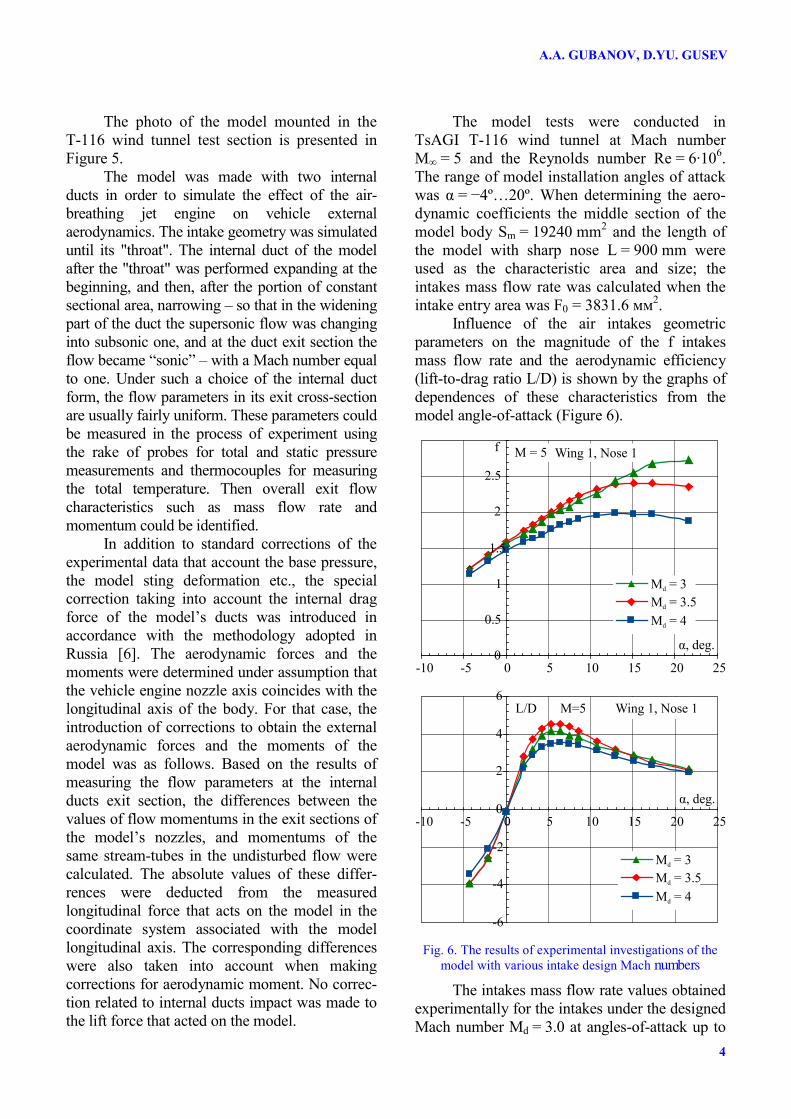
Influence of the air intakes geometric parameters on the magnitude of the f intakes mass flow rate and the aerodynamic efficiency (lift-to-drag ratio L/D) is shown by the graphs of dependences of these characteristics from the model angle-of-attack (Figure 6).
Fig. 6. The results of experimental investigations of the model with various intake design Mach numbers
The intakes mass flow rate values obtained experimentally for the intakes under the designed Mach number Мd = 3.0 at angles-of-attack up to

5
POTENTIAL USE OF WAVERIDER AND BUSEMANN BIPLANE IN AERODYNAMIC DESIGN OF HIGH-SPEED VEHICLES WITH AIR-BREATHING ENGINES
10º turned out to lower as compared to those ones obtained for Мd = 3.5. It might be because of separation zones occurrence in front of the air intakes entry sections when the shock waves caused by the central bodies went deeply into the intakes entries as it took place in the case of Мd = 3.0. In other respects, the intake mass flow rate changes correspond to logical qualitative assumptions about them that would result from the consideration of the shock waves locations without regard to separation zones: as Мd is increasing and the shock-waves is moving away from the intake entrance, the mass flow rate is decreasing. The decrease of the intakes mass flow rate leads to the corresponding growth of the spillage drag, and consequently the model lift-to-drag ratio decreases.
The highest values of the intakes mass flow rate in the range of angles of attack up to 10º which includes the supposed range of flight angles-of-attack of a real vehicle were obtained with the central bodies that correspond to Мd = 3,5. These central bodies were chosen as the main option for further research of other design parameters influence on vehicle external aerodynamics and intake performance.
The experimental researches have shown that the vehicle nose bluntness considered has practically no impact on the intakes mass flow rate. However, this shape has a noticeable impact on the lift-to-drag ratio. The impact of the outer wings area changes and of the nose bluntness impact on model external aero-dynamics is presented in Figure 7.
Fig. 7. The influence of the outer wings relative area and the nose bluntness on the lift-to-drag ratio
In Figure it is seen that the increase in the relative area of the outer wing Sw/Sm from 0.93 to 2.24 increases the maximum lift-to-drag ratio (L/D)max of the model by about 0.8, and that for the model with large wing (Sw/Sm = 2.24) the value of (L/D)max reaches approximately 5.3. For the Mach number M∞ = 5 this is a fairly high value.
The comparison of the CFD results obtained for the model considered with the experimental data on CD, external drag force coefficient the CL, lift force coefficient lift-to-drag ratio L/D, and intakes mass flow rate f is given in Figure 8. The CFD methodology used is described in Ref. [5]. Following this methodology, the local flow-fields around the considered configuration and the pressure distribution over its external surfaces were obtained by numerical integration of 3D-Euler equations. The skin friction drag force had been evaluated using the engineering techni-que based on simplified formulas for the flat plate frictional drag. As the parameters of the external flow for this problem the local flow parameters obtained by 3D-Euler equations are used.
Fig. 8. Comparison of the CFD results with the experimental data
Based the presented data it is possible to make a conclusion on the quite good agreement of the CFD results obtained by using the above-mentioned methodology [5] for the considering configuration (Мd = 3.5) with the experimental data. Implicitly, the noted agreement of the results indicates the absence of the noticeable impact of separation zones for the intakes with Мd = 3.5, as their impact is ignored by this particular CFD method.

A.A. GUBANOV, D.YU. GUSEV
6
2 Aerodynamic design of a vehicle based on the Busemann biplane concept
The classical Busemann biplane [7], as it is well-known, has no wave drag. However, it still has not found its practical exploitation since when using it, as compared to the conventional lifting systems for aircraft, the total area of the lifting surfaces approximately doubles, leading to the increased viscous friction drag, and the resulting gain in the vehicle drag force becomes negligible. However, for aerodynamic designs of high-speed vehicles with air-breathing jet engines such confi-gurations acquire the additional advantage consis-ting in the formation of zones with the intense compressed flow that passes through two oblique shock waves. This gives the possibilities for significant engines performance enhancement if the air intakes are located in these areas, and there-fore the possibility of practical implementtation of such configurations should be reconsidered.
It seems to be promising to consider the following scheme of the aircraft with two-stage preliminary compression of the flow before entering the air intake.
The pre-compression device consists of two compression surfaces and two side walls preventing the spatial spreading of the comp-ressed air (Figure 9). The first compression surface, the bottom one, is also a part of the upper surface of the vehicle fuselage. This surface creates an oblique shock wave by deflecting the flow up. The second compression surface is the top cover which reflects the shock wave caused by the first surface by deflecting flow in the opposite direction and giving it the direction which is close to the original one.
Fig. 9. The scheme of the device for two-stage pre-compression of the flow before air intake
At the design flight conditions of a vehicle the shock wave caused by the first compression
surface falls on the front edge of the top cover, reflects from it, and the reflected shock wave comes on a line of a break of the upper surface of the fuselage. After passing through two oblique shock waves the main part of the compressed air flow is captured by a conventional 2D air intake, and the remaining part (approximately one thirdth of the compressed flow) is returned to the external flow through the slots between the front edges of the air intake and all four of the internal surfaces of the pre-compression device. These slots are necessary in order to prevent the penetration of the boundary layers into the air intake and to ensure the start of the supersonic flow inside the pre-compression device within the desirable range of Mach number without any mechanical adjustment. In the bottom slot between the air intake and the top surface of the fuselage the wedge for diverting the boundary layer is installed.
The possible configuration of the aircraft, based on the Busemann biplane concept, which was developed and tested at TsAGI, is presented in Figure 10. The corresponding model was designed for cruise Mach number 4, and tested in TsAGI SVS-2 and T-116 wind tunnels.
Fig. 10. The scheme of the aerodynamic design of aircraft with two-stage flow pre-compression
in front of the air intake
At the designed flow conditions (М∞ = 4, α = 5°), the pre-compression device deflects the flow first up and then down at the angles, equal to 5º. As a result of pre-compression, the local flow Mach number at the intake inlet is reduced from 4 to 3.3, and the estimated value of the mass flow rate coefficient calculated without taking into account the effect of viscosity is fc = 1,83.
The model tests in the SVS-2 and T-116 wind tunnels have shown that the supersonic flow in the device under consideration is started
Cover 2D intake Side wall
Fuselage

7
POTENTIAL USE OF WAVERIDER AND BUSEMANN BIPLANE IN AERODYNAMIC DESIGN OF HIGH-SPEED VEHICLES WITH AIR-BREATHING ENGINES
at Mach numbers М∞ = 2.5 and higher, and the maximum value of the lift-to-drag ratio at the designed Mach number М∞ = 4 is (L/D)max = 4,7 (see Figure 11).
Fig. 11. The results of wind-tunnel tests of the vehicle design based on the Busemann biplane concept
The value obtained (L/D)max is lower as compared to that one obtained for the vehicle design based on waverider. However, due to the more intensive flow pre-compression it is possible to provide the higher performance of the air intake. For this model, the experimental studies of intake throttle characteristics were performed in TsAGI SVS-2 wind tunnel at Mach numbers М∞=4, 4.5 and 5. The results of these studies are presented in Figure 12 in the form of dependencies of maximum values of the f mass flow rate coefficient and the ν=pt/pt∞ total pressure recovery from α angle-of-attack.
The presented results show that the considered configuration allows getting the very high performance of the air intake, which is difficult to obtain by use of traditional technical solutions.
4 Conclusion The results of conceptual, CFD and experimen-tal researches allowed formulating the following main conclusions: 1. The aerodynamic configuration, formed on
the basis of the concepts of waverider and Busemann biplane, due to possibility of
Fig. 12. The results of experimental studies of the air intake throttle characteristics for the design based on the Busemann biplane concept

A.A. GUBANOV, D.YU. GUSEV
8
ensuring a high degree of airframe/ propulsion integration, have a considerable potential to be applied in aerodynamic design of high-speed vehicles with air-breathing jet engines.
2. The aerodynamic design of the high-speed vehicle based on the concept of waverider can provide the high aerodynamic efficiency and the improved engine performance due to the provision of the intensive flow pre-compression before air intakes.
3. The aerodynamic design of the aircraft with air-breathing jet engine based on the Busemann biplane concept, with acceptable level of aerodynamic efficiency can provide very high internal characteristics of the air intakes, which hardly ever could be obtained by use of traditional technical solutions.
References [1] Gubanov A A, Pritulo M F and Ruch’yev V M.
Theoretical investigation of airframe/inlet interference and integration for hypersonic vehicles. Z. Flugwiss. Weltraumforsch, 18, pp 379-382, 1994.
[2] Gubanov A A. Fundamental relations on airframe/propulsion integration for supersonic aircraft. Proc 5th European Conference for Aeronautics and Space Sciences – EUCASS 2013, Munich, Germany, 1-5 July 2013.
[3] Maikapar G I. Wave drag of non-axisymmetric body in supersonic flow. Applied Mathematics and Mechanics, Vol. XXIII, Issue 2, 1959 (in Russian).
[4] Nonweiler T. Aerodynamic problems of manned space vehicles. J. Royal Aeron. Society, Vol. 63, No. 585, 1959.
[5] Kovalenko V V and Khlevnoy V V. Complex of computer codes for calculating the supersonic flow over vehicles. Proc Second Sino-Russian Symposium on Aerodynamics, Beijing, CAE, 1992.
[6] Blishch V G. External and internal aerodynamic forces and moments of air-breathing jet powered vehicles and their models at incidence and sideslip. Trudy TsAGI, Issue 2328, 1987 (in Russian).
Contact Authors Email Addresses Mailto: [email protected] [email protected]
Copyright Statement The authors confirm that they, and/or their company or organization, hold copyright on all of the original material included in this paper. The authors also confirm that they have obtained permission, from the copyright holder of any third party material included in this paper, to publish it as part of their paper. The authors confirm that they give permission, or have obtained permission from the copyright holder of this paper, for the publication and distribution of this paper as part of the ICAS 2014 proceedings or as individual off-prints from the proceedings.