potential for intra-vehicle wireless automotive sensor ... · potential for intra-vehicle...
TRANSCRIPT

Potential for Intra-Vehicle Wireless AutomotiveSensor Networks
Tamer ElBattHRL Laboratories, LLC
ISSL Lab.,Malibu, CaliforniatelbattQdhrl.com
Cem SaraydarGeneral Motors
Corporation, R&D,Warren, Michigan
cem. saraydar(dgm. com
Michael AmesGeneral Motors
Corporation, R&D,Warren, Michigan
michael. ames(dgm.com
Timothy TaltyGeneral Motors
Corporation, R&D,Warren, Michigan
timothy. talty(Jigm. com
Abstract- We propose using a wireless network to facilitatecommunications between sensors/switches and control unitslocated within a vehicle. In a typical modern vehicle, the mostdemanding sensor will require a latency of approximately lessthan 1 msec with throughput of 12 kbps. Further, the networkwill need to support about 15 sensors with this requirement. Theleast demanding sensor will require a latency of approximately 50msec with data throughput rate of 5 bps and will need to supportabout 20 of these types of devices. Initial part of this paper givesan overview of the issues spanning several layers of the protocolstack. Then, we focus on the Medium access control (MAC) layerand derive necessary design parameters based on given networkrequirements. We evaluate the IEEE 802.15.4 standard withrespect to its suitability for use in a prospective intra-vehiclewireless sensor network.
I. INTRODUCTION
Recent works have discussed the use of vehicles in wide areasensor networks where the vehicles are the sensor nodes[1][2][3]. In general, these types of sensor networks requireconnectivity to other vehicles and/or some infrastructure andcan be classified as inter-vehicle or vehicle-to-vehiclenetworks. These applications include: asset tracking,communication of traffic, weather, and road conditions.However, very limited attention, if at all, has been given towireless sensor networks (WSN) that operate within a vehicle.Such networks have unique requirements different from othertypes of WSNs. Therefore, a careful design study is needed forwireless automotive sensor networks (WASN).A current production vehicle can have greater than 150
sensors and switches. This number is expected to grow asadditional features are added to vehicles. For example, GeneralMotors is leading the industry by offering 'StabiliTrak' as astandard by 2007 in utility vehicles and vans[4]. This and othernew features will result in even more sensors and switchesbeing integrated into vehicles and will further increase thecomplexity, cost and weight of the wiring harness. The wiringharness is the heaviest, most complex, bulky and expensiveelectrical component in a vehicle and it can contribute up to 50kg to the vehicle mass [5]. Given the weight, complexity andcost of the wiring harness, it is desirable to investigate otheralternatives, such as WSNs. Intra-vehicle WSNs have thepotential to solve this problem but can they deliver the samelevel of performance and reliability offered by wiredsubsystems?
In the next section, we begin by over viewing major issuesregarding the implementation of WASNs. Due to space
limitations, we limit our analysis of WASN to a singlesubsystem (e.g. door subsystem) with emphasis on the M\ACdesign. The paper presents results of our analysis based uponin-vehicle application requirements and state-of-the-art shortrange wireless standard, namely IEEE 802.15.4.
II. IN-VEHICLE SENSORNETWORKS
Low-current sensors and switches span a diverse range ofrequirements, depending on their impact on safety,comfort/convenience features and vehicle controls. This paperlooks into replacing the wires that carry data between thevehicle's controllers and the sensors/switches with wirelesslinks. We refer to the resulting wireless architecture as theWASN. WASNs have very specific features that distinguishthem from other applications of WSNs. There are severaldesign issues that need to be addressed in order to come upwith a viable end-to-end system realization. The following aresome of the considerations by the authors and are included inpapers currently under preparation:1. Heterogeneity: One of the more challenging tasks is tocome up with a good understanding of the set of requirementsto be input for the design effort. Due to the variety of sensingapplications within a vehicle, there is a heterogeneous networkof sensors, making a one-size-fits-all solution very difficult.2. Wireless Channel: Part of current research by the authorsis directed at characterizing the propagation environmentwithin a vehicle. Fading and path loss characteristics of theintra-vehicle wireless channel will greatly impact the designchoices (e.g. channel coding).3. Modulation waveform: The choice of the waveform hasimplications on error performance and energy consumption.Since WASNs need to employ ultra power-efficient devices,the choice of modulation waveform and type has gravesignificance.4. Wireless networking: The WASN proposed in this paperneeds to work in harmony with the existing data buses thatconnect the various electronic controllers on a vehicle. Thus,hybrid architecture emerges. The connectivity of the wirelesssensors/switches to these controllers are determined as a resultof various trade-off relationships including factors such as cost,power consumption and latency.5. Medium access: The radio resources are shared betweenall wireless sensors/switches within the WASN. The way thecommon resource is shared determines the resulting latency in

packet delivery. M\AC layer design is the subject of the nextsection.
III. LATENCY ANALYSIS AND MAC DESIGN IMPLICATIONS
A. BackgroundOur objective in this section is two-fold: i) Establish bounds
on MAC parameters in order to meet the hard latencyrequirements dictated by state-of-the-art in-vehicle electronicsubsystems and ii) Quantify the latency guarantees supportedby short-range wireless technologies readily available in themarket, namely IEEE 802.15.4 (ZigBee). Replacing signalwires, for some of the sensor/switches in selected subsystems,with wireless communications is subject to maintaining thesame order of latency and reliability of communicationcurrently achieved by wired connectivity. This is of paramountimportance for the control software onboard each electroniccontrol unit (ECU) to get its input on time, execute the controlalgorithm and deliver its monitor/control output on time. Thiswould have direct implications on the MAC scheme, which isthe subject matter of this section.
Uplink Nodes
D.,.I. N ,d,
Figure 1. An example of a wireless star in-vehicle subsystem
B. NetworkModel andAssumptions1. A wireless subsystem is modeled as a star network as shownin Figure 1. Even though some nodes might not be able toreach the ECU over a single-hop (due to non-line-of-sight(NLOS) or other wireless channel impairments), we focus onsingle-hop stars in this first step of the study.2. We focus on contention-free multiple access schemes due toits collision-free nature which is essential for providing latencyguarantees. Therefore, we focus on slotted scheduled 1\4ACschemes where each sensor/switch reading fits exactly in asingle time slot.3. We assume N uplink nodes who wish to communicate theirreadings to the ECU over the shared wireless medium.4. We assume that the underlying PHY layer is reliable (i.e.error-free) whereby a transmission taking place in acontention-free manner in any slot is successfully receivedwith probability 1. This is justified by the low data raterequirement of the applications at hand (tens of Kbps) and theemergence of short-range wireless technologies, e.g. UVsBowhich could effectively trade link bandwidth for reliability.5. We focus on the nMAC and interference issues within asingle in-vehicle subsystem rather than interference between
different subsystems. Mitigating inter-subsystem interferenceand external sources of interference (e.g. hands-free Bluetooth,WiFi, etc.) requires the development of interference-resilientPHY layer waveforms which is out of the scope of this paperand is a subject of ongoing research.6. We focus on replacing signal wires connecting switches andlow-current sensors to the ECU with wireless links. High-current wires such as those which feed actuators are notconsidered.7. We assume that uplink and downlink communications areseparated, in a manner similar to cellular systems, either in thetime domain via Time Division Duplexing (TDD) techniquesor in the frequency domain via Frequency Division Duplexing(FDD) techniques. This is essential in order to prevent self-interference that may arise at the ECU. FDD seems to be afavorable design choice if multi-channel technologies, e.g.ZigBee, are used since the underlying IEEE 802.15.4 standardoperating at 2.4 GHz supports 16 orthogonal channels.8. We assume that each sensor node has a Transmission Bufferthat stores packets awaiting transmission. We also assume thatpackets to be transmitted arrive at the buffer of any sensornode periodically, i.e. the traffic arrival pattern at each node isdeterministic.
C Sensor-to-ECULatency Requirements AnalysisFigure 1 shows an example of a wireless star vehicle
electronic subsystem where the "uplink nodes", typicallysensors and switches, communicate their sample measurementsfor processing by the ECU software modules. These modulesgenerate a decision/reading that is fed to the "downlink nodes",typically actuators and dashboard displays. Our main target inthis section is to establish bounds on TDMA MAC parameters(i.e. slot and frame durations) in order to meet the hard latencyrequirements dictated by state-of-the-art in-vehicle electronicsubsystems. The overall latency to communicate a readingfrom uplink node Ui to its corresponding downlink node D, isgiven by,
Overall Latency(i) = UL Latency(i) + ECU Processing Latency +
DL Latency(i)
where UL Latency(i) is the latency involved incommunicating a sample measurement from node Ui to theECU and DL Latency(i) is the latency incurred forcommunicating the ECU output to node DP. Finally, theECU_Processing_Latency is the time required for the ECUsoftware modules to process the input data. Typically,processing delays are orders of magnitude less thancommunication delays and, hence, can be safely ignored.
In this analysis, we focus primarily on the uplink latency dueto: i) It is upper bounded by the latency requirements of in-vehicle subsystems, denoted Required-Latency, and defined asthe deadline by which the sensor sample should be availablefor the ECU software module and ii) It has direct impact on thedesign of MAC schemes. Thus, the problem at hand boilsdown to specifying the MAC parameters that satisfy thefollowing conditions:

UL Latency(i) < Required Latency(i) 'V i
Assuming the time slots are grouped into frames where eachframe consists of S slots, the problem can be formulated asfollows,
Given S slots/frame and N uplink nodesWhat are the upper and lower bounds on the Slot-Duration? (1)s.t.
UL_Latency(i) < Required_Latency(i) i 1,2,..., NNotice that the uplink latency accommodates the followingtypes of latencies,
UL Latency(i) = QLatency(i) + Tx_Time(i) + Propagation Delay
where, QLatency(i) is the time spent by the packet queued inthe buffer of node i, Tx Time(i) is the time needed fortransmitting the packet over the air and is given byPacket_Size(i) and the propagation delay can be ignored dueLink Bit Rateto the short distance (typically few meters) of wavepropagation inside the vehicle. Accordingly, problem (1)reduces to determining upper and lower bounds on the slotduration (which translates immediately to bounds on the frameduration) that satisfy the following condition:
QLatency(i) <Required Latency(i) -Tx_Time(i) i (2)
The next step is to characterize the QLatency(i) for anarbitrary sensor node i. In this paper, we limit our attention tothe case where all uplink nodes in the subsystem arehomogenous, i.e. packet arrival rates, packet sizes and latencyrequirements are the same for all sensor nodes communicatingwith the same ECU. Accordingly, each uplink node is assignedone slot per frame and, hence, the number of slots per framebecomes S = N. Recall that the packet arrival process at eachnode is deterministic and the packet transmission time isdeterministic too, however, QLatency(i) may still varydepending on the instant of node i's packet arrival within theframe relative to the location of the slot assigned to node i.Since all nodes experience the same performance under thehomogenous node assumption, we will drop the node index i inthe rest of the analysis. Under the best-case scenario, a packetarrives at node i within the slot immediately preceding the slotassigned to i and, hence, 0 < Min_QLatency < 1 slot. On the otherhand, N-1 < Max_QLatency < N slot when a packet arrives at node iwithin the slot assigned to i or the one immediately following it.
Clearly, the worst-case latency should be the driving forcefor M\AC design in order to provide latency guarantees wellwithin the specified sensor latency requirements. Accordingly,(2) can be re-written as,
Max QLatency < Required Latency- Tx Time (3)
Substituting for Max_QLatency in (3) yields,N * Slot-Duration < Required Latency - Tx-Time
This yields an upper bound on the Slot Duration parameter,
Re quired Latency -Packet SizeSlot Duration < Link Bit Rate (4)
N
Notice that the inequality in (4) establishes constraints onM\AC and PHY layer parameters dictated by the latencyrequirements. It provides an upper bound on the slot duration(which is a MAC layer parameter) as a function of the numberof uplink nodes (N), application latency requirements, packetSize and link bit rate. Intuitively, as N increases, the slotduration decreases in order to support the same latencyrequirement. Moreover, as the Required Latency becomesmore stringent, smaller slot duration is essential to support thesame number of uplink nodes. However, there is a limit onhow short a slot could be that is dictated by the transmissiontime and guard bands used for synchronization. This, in turn,dictates the following lower bound on the Slot-Duration:
Re quired LatencyPacket -Sie
Packet Size <Slot Duration < Link Bit RateLink Bit Rate N
(5)
As the Required Latency becomes more stringent (<10msec), the upper bound reaches the lower bound and theTx Time becomes the limit. At this point, the Link Bit Rateneeds to be increased in order to maintain a reasonable rangefor the Slot-Duration degree of freedom.
D. Characterizing the LatencyPerformance ofIEEE 802.15.4
IEEE 802.15.4 OverviewOur prime objective in this section is to quantify the latency
guarantees that can be provided by the IEEE 802.15.4 standard
B......
Figure 2. Superframe Structure with 7 Guaranteed Time Slots (GTS)
[6] when used for in-vehicle wireless applications. Hence, weprovide the M\AC and PHY assumptions and specifications thatare relevant to the analysis. TABLE I shows the 802.15.4 PHYparameters adopted in the analysis.The 802.15.4 supports two types of MAC schemes, namely
contention-based CSMA/CA MAC during the contentionaccess period (CAP) and contention-free M\AC during thecontention-free period (CFP) using the notion of guaranteedtime slots (GTS). The CAP and CFP periods alternate and theyboth constitute what is referred to as the M\AC super-frame.The boundary between the CAP and CFP is sliding dependingon the carried traffic mix and associated QoS requirements.
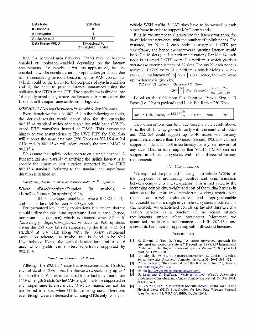
TABLE I802.15.4 PHY PARAMETERS USED IN THE ANALYSIS
Waveform DSSSOperating Frequency 2.4 GHz
802.15.4 personal area networks (PAN) may be beacon-enabled or nonbeacon-enabled depending on the latencyrequirements. For in-vehicle wireless applications, beacon-enabled networks constitute an appropriate design choice dueto: i) transmitting periodic beacons by the PAN coordinator(which could be the ECU) for the purposes of synchronizationand ii) the need to provide latency guarantees using thecollision-free GTSs in the CFP. The superframe is divided into16 equally sized slots, where the beacon is transmitted in thefirst slot in the superframe as shown in Figure 2.
IEEE 802.15.4 Latency Guaranteesfor In-vehicle StarNetworksEven though we focus on 802.15.4 in the following analysis,
the derived results would apply also for the emerging802.15.4a standard which adopts an ultra wide band (UWB)-based PHY waveform instead of DSSS. This assessmenthinges on two assumptions: i) The UWB PHY for 802.15.4awill support the same data rate (250 Kbps) as 802.15.4 at 2.4GHz and ii) 802.15.4a will adopt exactly the same MAC of802. 15.4.We assume that uplink nodes operate on a single channel. A
fundamental step towards quantifying the uplink latency is tospecify the minimum slot duration supported by the IEEE802.15.4 standard. Referring to the standard, the superframeduration is defined as:
Superframe Duration = aBaseSuperframeDuration * 2So symbols
Where aBaseSuperframeDuration (in symbols)aBaseSlotDuration (in symbols) * 16,
SO = macSuperframeOrder where 0 < SO < 14,and aBaseSlotDuration = 60 symbolsFor guaranteed low latency applications, it is evident that we
should utilize the minimum superframe duration (and, hence,minimum slot duration) which is attained when SO = 0.Accordingly, Superframe Duration becomes 960 symbols.Given the 250 kbps bit rate supported by the IEEE 802.15.4standard at 2.4 GHz along with the 16-ary orthogonalmodulation scheme, the symbol rate is found to be 62.5Ksymbols/sec. Hence, the symbol duration turns out to be 16[tsec which yields the shortest superframe supported by802.15.4,
Superframe_Duration = 15.36 msec
Although the 802.1.5.4 superframe accommodates 16 slots,each of duration 0.96 msec, the standard supports only up to 7GTSs in the CFP. This is attributed to the fact that a minimumCAP of length 8 slots (aMinCAPLength) has to be supported ineach superframe to ensure that MAC commands can still betransferred to nodes when GTSs are being used. Therefore,even though we are interested in utilizing GTSs only for the in-
vehicle WSN traffic, 8 CAP slots have to be wasted in eachsuperframe in order to support MAC commands.
Finally, we attempt to characterize the latency variation, forin-vehicle star networks, with the number of uplink nodes. Forinstance, for N = 7 each node is assigned 1 GTS per
superframe, and hence the worst-case queuing latency wouldbe 9+7 = 16 slots (i.e. 1 superframe duration). For N = 14, eachnode is assigned 1 GTS every 2 superframes which yields a
worst-case queuing latency of 32 slots. For any N, each node isassigned 1 GTS every N superframes which yields a worst-case queuing latency of 16 [N /7] slots. Hence, the worst-caseuplink latency is given by,
802.15.4_UL_Latency QLatency + TxTimeN ~~~~~Pack-et Size
(16 - Slot Duration) +7 - Link_Bit Rate
Based on the 0.96 msec Slot Duration, Packet Size = 17Bytes (i.e. 2 bytes payload) and Link_Bit_Rate = 250 Kbps,
802.15.4_UL_Latency 1536 [71 + 0.544 msec N > I
Two observations can be made based on the result above.First, the UL-Latency grows linearly with the number of nodesand 802.15.4 could support up to 40 nodes with latencyguarantees not more than 100 msec. Second, 802.15.4 can notsupport smaller than 15.9 msec latency for any star network ofany size. This, in turn, implies that 802.15.4 MAC can notsupport in-vehicle subsystems with sub millisecond latencyrequirements.
IV. CONCLUSIONS
We explored the potential of using intra-vehicle WSNs forthe purposes of monitoring, control and communicationbetween components and subsystems. This is motivated by theincreasing complexity, weight and cost of the wiring harness inaddition to the versatility of wireless networking which opensroom for novel architectures and reprogrammablefunctionalities. For a single in-vehicle subsystem, modeled as a
star network, we established bounds on the slot duration of a
TDMA scheme as a function of the sensor latencyrequirements among other parameters. Moreover, we
quantified the latency performance of IEEE 802.15.4 andshowed its limitation in supporting sub-millisecond latencies.
REFERENCES
[1] H. Sawant, J. Tan, Q. Yang, "A sensor networked approach forintelligent transportation systems," Proceedings. IEEE/RSJ InternationalConference on Intelligent Robots and Systems. Volume 2, 28 Sept.-2 Oct.2004, pp. 1796 -1801.
[2] I.F. Akyildiz, W. Su, Y. Sankarasubramaniam, E. Cayirci, "WirelessSensor Networks: A survey," Computer Networks 38 (2002) 393-422.
[3] C. Evans-Pughe, "The connected car," IEE Review, Volume 51, Issue 1,Jan. 2005 Page(s):42 - 46.
[4] Online, htln:Hwww.orm.com/compagy/oplygm/[5] G. Leen and D. Hefferna, "Vehicles Without Wires", Automotive
Electronics, Computing and Control Engineering Journal, October 2001,pages 205-211
[6] IEEE 802.15, Part 15.4: Wireless Medium Access Control (MAC) andPhysical Layer (PHY) Specification for Low-Rate Wireless PersonalArea Networks (LR-WPANs), IEEE, October 2003.
Data Rate 250 Kbps# Channels 16# bits/symbol 4# chips/symbol 32Data Frame PPDU 15+payload to
31 +payload Bytes