positive waterproofing from negative side · 2014-12-24 · positive waterproofing from negative...
TRANSCRIPT
88 The Masterbuilder - July 2013 • www.masterbuilder.co.in
Positive Waterproofing from Negative Side
With the increase in infrastructural projects, use of underground constructions is tremendously increased. Scarcity of land at ground level necessitates underground
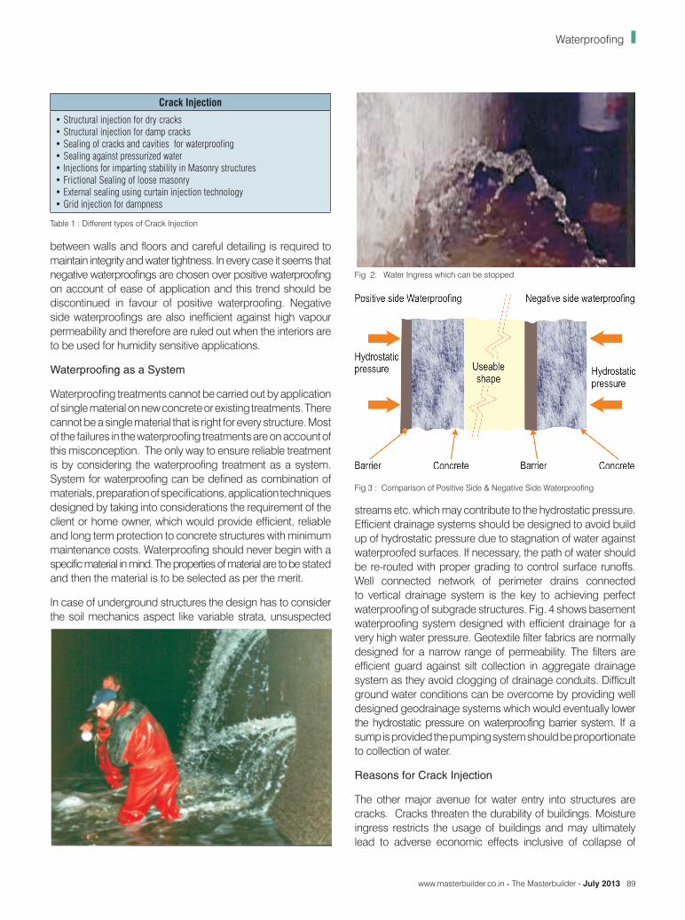
metros in crowded cities. Distances of rail and roads are lowered by tunelling through mountains and under the bed of water. Deeper basements are part of construction activities civil and geotechnical engineers are facing challenges firstly to gather geotechnical data and later to select construction techniques to complete projects on schedule. In spite of technological advancements in geological strata mappings, the real problems are faced while actual construction is going on. Since the exact nature of strata cannot be predetermined, civil engineers have to resolve problems at site. Rehabilitation of underground structures pose major problems as usually only the internal face is accessible and the problem is always on the other side. Movement of water is one of the major impediment to underground construction. Leakages can be uncontrollable and have to be repaired immediately. If leakages are not arrested early, the consequential damages to structures can be time consuming and costly to repair throwing the deadlines out of gear and endangers the very stability of structures. Fig 1 shows different types of Cracks in Tunnel linings. Fig 2 shows critical water ingress.
Any repair based on predetermined material is bound to be ineffective. Sound principles of civil engineering is the
Samir SurlakerManaging Director, MC-Bauchemie
Waterproofing
base to all repairs, rehabilitation or retrofitting. So positive waterproofing is possible from negative side.
In many waterproofing projects, damp-proofing systems are specified and waterproofing is expected of them. There is a major difference between waterproofing and damp-proofing. As per ACI Committee 515 report, waterproofing and damp-proofing is defined differently. Waterproofing is a treatment of a surface or structures to prevent the passage of water under hydrostatic pressure. Dampproofing is a treatment of surface or structure to resist the passage of water in the absence of hydrostatic pressure. While designing the waterproofing system, actual service conditions are to be borne in mind. It should be decided at this stage whether damp-proofing is required or waterproofing is desired.
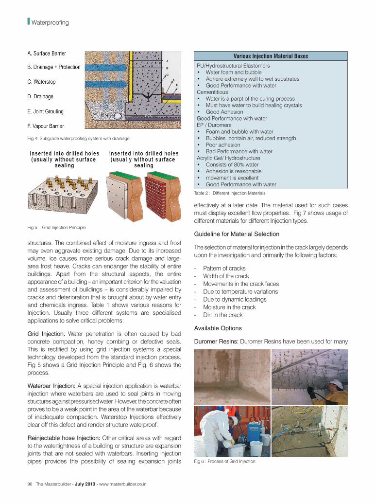
Positive side waterproofing systems are applied on the same side as the applied hydrostatic pressure and negative side waterproofing systems are placed on the side opposite the applied hydrostatic pressure. Previously negative side waterproofing was only adopted when access to positive side was unavailable as in case of common boundary lines. Negative side waterproofing systems were also used as repair strategy because the positive side was inaccessible and the back fill or protective layers had to be removed. There is an increasing trend in the country to specify negative side waterproofing.
If the negative side waterproofing systems are unavoidable, extreme care should be exercised during the construction process. First and foremost, the concrete cast should be of very low permeability without honeycombing, cracks, crevices or any other surface defects. Efficient drainage systems are mandatory. Provision of water stops is also mandatory, as this is first line of defense in case of negative waterproofing. Fig 3 shows schematically the positioning of positive side and negative side waterproofing.
It should be clearly borne in mind that negative side waterproofing accords no protection to concrete if soils contain corrosive chemicals. Extreme precautions should be taken at joints
www.masterbuilder.co.in • The Masterbuilder - July 2013 89
between walls and floors and careful detailing is required to maintain integrity and water tightness. In every case it seems that negative waterproofings are chosen over positive waterproofing on account of ease of application and this trend should be discontinued in favour of positive waterproofing. Negative side waterproofings are also inefficient against high vapour permeability and therefore are ruled out when the interiors are to be used for humidity sensitive applications.
Waterproofing as a System
Waterproofing treatments cannot be carried out by application of single material on new concrete or existing treatments. There cannot be a single material that is right for every structure. Most of the failures in the waterproofing treatments are on account of this misconception. The only way to ensure reliable treatment is by considering the waterproofing treatment as a system. System for waterproofing can be defined as combination of materials, preparation of specifications, application techniques designed by taking into considerations the requirement of the client or home owner, which would provide efficient, reliable and long term protection to concrete structures with minimum maintenance costs. Waterproofing should never begin with a specific material in mind. The properties of material are to be stated and then the material is to be selected as per the merit.
In case of underground structures the design has to consider the soil mechanics aspect like variable strata, unsuspected
Crack Injection
• Structural injection for dry cracks• Structural injection for damp cracks• Sealing of cracks and cavities for waterproofing• Sealing against pressurized water• Injections for imparting stability in Masonry structures• Frictional Sealing of loose masonry• External sealing using curtain injection technology• Grid injection for dampness
Table 1 : Different types of Crack Injection
Fig 2: Water Ingress which can be stopped
Fig 3 : Comparison of Positive Side & Negative Side Waterproofing
streams etc. which may contribute to the hydrostatic pressure. Efficient drainage systems should be designed to avoid build up of hydrostatic pressure due to stagnation of water against waterproofed surfaces. If necessary, the path of water should be re-routed with proper grading to control surface runoffs. Well connected network of perimeter drains connected to vertical drainage system is the key to achieving perfect waterproofing of subgrade structures. Fig. 4 shows basement waterproofing system designed with efficient drainage for a very high water pressure. Geotextile filter fabrics are normally designed for a narrow range of permeability. The filters are efficient guard against silt collection in aggregate drainage system as they avoid clogging of drainage conduits. Difficult ground water conditions can be overcome by providing well designed geodrainage systems which would eventually lower the hydrostatic pressure on waterproofing barrier system. If a sump is provided the pumping system should be proportionate to collection of water.
Reasons for Crack Injection
The other major avenue for water entry into structures are cracks. Cracks threaten the durability of buildings. Moisture ingress restricts the usage of buildings and may ultimately lead to adverse economic effects inclusive of collapse of
Waterproofing
90 The Masterbuilder - July 2013 • www.masterbuilder.co.in
effectively at a later date. The material used for such cases must display excellent flow properties. Fig 7 shows usage of different materials for different Injection types.
Guideline for Material Selection
The selection of material for injection in the crack largely depends upon the investigation and primarily the following factors:
- Pattern of cracks- Width of the crack- Movements in the crack faces- Due to temperature variations- Due to dynamic loadings- Moisture in the crack- Dirt in the crack
Available Options
Duromer Resins: Duromer Resins have been used for many
Fig 4: Subgrade waterproofing system with drainage
Fig 5 : Grid Injection Principle
structures. The combined effect of moisture ingress and frost may even aggravate existing damage. Due to its increased volume, ice causes more serious crack damage and large-area frost heave. Cracks can endanger the stability of entire buildings. Apart from the structural aspects, the entire appearance of a building – an important criterion for the valuation and assessment of buildings – is considerably impaired by cracks and deterioration that is brought about by water entry and chemicals ingress. Table 1 shows various reasons for Injection. Usually three different systems are specialised applications to solve critical problems:
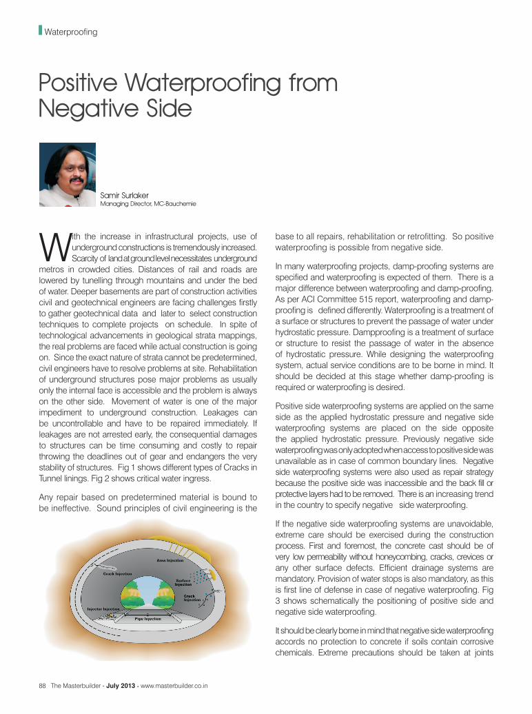
Grid Injection: Water penetration is often caused by bad concrete compaction, honey combing or defective seals. This is rectified by using grid injection systems a special technology developed from the standard injection process. Fig 5 shows a Grid Injection Principle and Fig. 6 shows the process.
Waterbar Injection: A special injection application is waterbar injection where waterbars are used to seal joints in moving structures against pressurised water. However, the concrete often proves to be a weak point in the area of the waterbar because of inadequate compaction. Waterstop Injections effectively clear off this defect and render structure waterproof.
Reinjectable hose Injection: Other critical areas with regard to the watertightness of a building or structure are expansion joints that are not sealed with waterbars. Inserting injection pipes provides the possibility of sealing expansion joints
Various Injection Material Bases
PU/Hydrostructural Elastomers• Water foam and bubble• Adhere extremely well to wet substrates• Good Performance with waterCementitious• Water is a parpt of the curing process• Must have water to build healing crystals• Good Adhesion Good Performance with waterEP / Duromers• Foam and bubble with water• Bubbles contain air, reduced strength• Poor adhesion• Bad Performance with waterAcrylic Gel/ Hydrostructure• Consists of 80% water• Adhesion is reasonable• movement is excellent• Good Performance with water
Table 2 : Different Injection Materials
Fig 6 : Process of Grid Injection
Waterproofing

92 The Masterbuilder - July 2013 • www.masterbuilder.co.in
years for the rigid injection of cracks in dry structural sections. Epoxy resins of very low viscosity can be injected into the finest of cracks. This guarantees a strong permanent bridging of both sides of the crack, thus restoring bearing capacity for the designed loads planned. This process can also be carried out where the structure is also subject to vibration. Duromer resins of varying viscosity can be used for injection and impregnation depending on the width of the crack.
Elastomer Resins: If rigid injection material is used the cracks become visible after injection or new cracks develop adjacent to old cracking. High quality elastomer resins are a solution for avoidance of such occurences. Elastomer resins can be designed with distinct pore structures. An homogenous closed cell structure is formed which enables safe sealing. The integrated compression and decompression reserves in the cell structure absorb the expansion and the contraction in the crack. The effectiveness and permanency of the seal is guaranteed by the ability to expand and contract in sympathy with the crack movement while maintaining the tenacious bond to crack surfaces.
Hydrostructural Resins: Hydrostructural resins cure to form elastic membrane and impervious seals when encountered with water. This property is very useful when the external of building is not accessible like in buried structures and when the external waterproofing envelope is damaged. By drilling
How to choose the right product - Job Conditions
These are problems which injection can solveSealing Coming from• movement cracks• stationary cracks• construction joints• expansion joints• bad construction• All needs flexible fillingStrengthening Cracks coming from• mechanical damages damages caused by earth movements• general wear and tear• Bad construction• All needs rigid filling
Table 3: Selection of Materials
Fig 7: Crack V/s. Materials to be used
Fig 8: Showing Hydrostructure Resin PU Foam
through the structure to the interface between existing water-proofing membrane or protection board, hydrostructure gels can be injected to recreate the seal. Hysdrostructure resins can be designed for high chemical and mechanical resistances. Fig 8 shows water reactive Pu Foam. They guarantee permanent elasticity, tenacious and isotopic bonding and unique skin effect. Fig. 7 different material for different injection types.
The Process of Injection
After completion of diagnosis and selection of materials for injection the work of injection passes through following stages.
- Preparation of the crack- Location of points (nipples) for injection- Fixing of injection points- Surface sealing of cracks- Injection of resin proper- Removal of nipples and plugging- Removal of sealing material- Final surface treatment after injection resin/grout hardens
Components and Machinery
Proprietary materials and machineries are available for treating the cracks by injection system. The materials are mostly synthetic resin based or cement based. The synthetic resins are usually two component materials based on epoxies and polyurethane. The cement based materials are invariably modified with polymers to impart flowability, non shrinking characteristics, better bonding etc.
The first step is selection of packers. It is important that packers are in the form of metal or plastic tubes. They should be able to be connected to the injection nozzle, so that the pressure if any should not be lost. Thereafter, it should be possible to tie or seal the packers, so that the resin is not lost and they should be removable to enable the surface smoothening. Normally there are two types of packers.
Waterproofing

www.masterbuilder.co.in • The Masterbuilder - July 2013 93
Waterproofing
The packers, which can be stuck to the surface of the structure along the line of crack, if the surface is even and packers which are to be introduced in the structure after boring and inclined at 450C to the crack plane. The spacing of injection points depend upon the width of crack as well as the porosity of concrete. However, as a thumb rule, in case of adhesion packer, the spacing should be about 50% of concrete cross section. Adhesion packers should not be used for high pressure injections exceeding 60 bars. Fig. 9 shows both types of packers.
Packer or Packer Systems are the link between the structure and face of the crack and the injection nozzle. Packers must be of adequate size to gurarantee the flow of injection resin to the desired place with or without being displaced or debonded due to injection pressures or rebounds. The critical selection depends upon the access to crack, quality of surface, surface condition as well as pressures used in injection process. Table 5 shows Technical data about packers.
There are Normally Three Types of Packers used Under General Conditions
Adhesion Packers: for the injection of dry cracks, cavities and
substrates with epoxy and polyurethane resins where surface conditions are suitable.
Drill or Bore Injection Packers: for the injection of dry, moist and water bearing (pressurized and Non-presurrized) cracks, cavities and substrates with epoxy, Acrylic and Polyurethane resins
Hammer Packers: for the injection of cement injections and acrylic gels. Fig. 10 shows different packers for Injection.
The more sophisticated the machinery, the better the control and therefore the performance. Secifications written in office can be perfectly adhered to at site and controlled via good supervision. Present day gel injections with a very low setting and reaction times require 2 component machineries which can mix materials at the nozzle. Fully computerized attachments can measure the pressure, control per point, idle time, time taken for injections and this data can be mentioned for documentation purpose. Further such data can be used by owner to control the quantity of repair process and materials respectively. The supervision at site is very essential to ensure that the specifications are strictly adhered to. The temperature plays very important role in the performance of some resin based systems: and therefore manufacturers instructions as to the environmental temperature as well as the temperature of the component in which the material in injected are to be followed.
The simplest of the injection method is the brush injection. The resin is brushed on the non moving surface cracks and is absorbed in capillary action. In case of pressureless injection the material is poured into the packers especially in case of pipes acting as packers, the use of such injection depends largely on the dimensions of the crack. In case of structural cracks of the width 0.2 - 1.0 mm, it is advisable to resort to low pressure injection. This low pressure can either be created with hand guns (sealant guns, grease guns etc) or a normal compressor used at site. The pressure developed is around 6 - 10 bars. Depending upon the crack widths and depths, high pressure injections can be resorted to for structural crack repairs. It is possible to develop pressures to the tune of 500 bars using mechanical or pneumatic transmissions. The injection method should be clearly specified prior to the commencement of the work and should be supervised to conform with the specifications. Fig 11 shows Injection Machineries.
Modern Injection Techniques
When problems cannot be resolved by conventional methods of grouting and injections the resort can be made to modern injection techniques in which external envelope can be created by working from inside the structures. This means creating positive waterproofing from negative side. This
Fig 9: Different Packers for Injection
Fig 10: Showing Different Packers
94 The Masterbuilder - July 2013 • www.masterbuilder.co.in
technology involves new machineries, new materials and trained applicators as the technology is state of art. In order to ensure durability and, in particular, bearing capacity, the permissible crack width in the relevant norms is confined to a harmless size. If this width is exceeded, there is a danger of further secondary damage to the building or structure. Cracks smaller than the permissible maximum width can, when penetrated with water, also detrimentally affect the structure concerned. To maintain and restore operational use, any cracks appearing in a building or structure must be sealed. Various injection procedures are used depending on the cause of the crack and individual requirements. The material is injected into the crack through injection packers and a specially designed machine. The objective is the closing and sealing of the crack as well as the expandable or rigid bridging of the sides of the cracks.
Epoxy resins have been used for many years for the rigid injection of cracks in dry structural sections. Epoxy resins of very low viscosity, can be injected into the finest of cracks. This guarantees a strong permanent bridging of both sides of the crack, thus restoring bearing capacity for the loads planned. This process can also be carried out where the structure is subject to vibration. Epoxy resins of varying viscosity can be used for injection and impregnation depending on the width of the crack. Mineral injection systems also fulfil the requirements of rigid injection.
The newly developed cement based suspensions are suitable, in particular, for injecting moist cracks bearing pressureless water as well as dry cracks and can even be used for the rigid injection of cracks down to 0.2 mm vide.
Even newly erected buildings and structures often show signs of defects in the form of cracks or cavities caused by damage. Mineral injection systems really come into their own in these cases because they are not sensitive to the moisture
contained in new concrete. Rectifying defects with mineral polymer cement injection makes the building or structure appear as a unified entity for inspection purposes as well as restoring the structural integrity.
Structures located in groundwater and pressure water environments, e.g. tunnels, reservoirs, etc., often display pervious areas, which can considerably impair the use of the structure in question. These pervious areas can be caused by cracks, voids or faulty seals. Water-bearing cracks make particular demands on injection technology. The objective is to seal an existing structure to prevent water penetration without impeding the normal expansion and contraction of the structure. Structures with water-bearing cracks are normally accessible from one side only. If the actual seal can only otherwise be repaired at a great expense, the only truly economical way of achieving permanent success is to use injection technology developed polyurethane-based injection systems for such cases and these have proved successful over many years. Permanent seals are achieved by using PU Injection with its outstanding material properties which was by forming an even closed pore structure. The result is a plastic workable product which makes flexible injection sealing possible. Even cracks bearing pressurized water can permanently sealed. In this case, a fast-foaming water-stopping polyurethane, can be used.
Water penetration is often caused by bad concrete compaction, honey combing or defective seals. This is rectified by using grid injection systems, a special technology developed from the standard injection process. Fig. 5 shows the principle of grid injection of creating positive waterproofing from negative side. Fig. 6 shows the process of injection and grid matrix.
A special injection application is waterbar injection where waterbars are used to seal joints in moving structures against
How to choose the right product - Site Conditions
Few are only 2 site conditions which has to be taken into con-dition when injection shall be attempted
Wet Cracks • movement cracks• stationary cracks• construction joints• expansion joints• bad construction• Needs Hydrostructure Resins and gels for flexible fillingDry Cracks• Non moving cracks• mechanical damages• damages caused by earth movements• general wear and tear• bad construction• Needs Duromers for Rigid filling
Table 4 : Selection of Materials Fig 11: Injection Machineries
Waterproofing

96 The Masterbuilder - July 2013 • www.masterbuilder.co.in
pressurized water. However, the concrete often proves to be a weak point in the area of the waterbar because of inadequate compaction. This technology is further proof of the effectiveness of solving structural problems with special injection systems.
Other critical areas with regard to the watertightness of a building or structure are expansion joints that are not sealed with waterbars. Inserting injection pipes provides the possibility of sealing expansion joints effectively at a later date.
The material used for such cases must display excellent flow properties. Viscocities play a major role in injection techniques. The reaction times also are very important. Secondary injections are a must.
All cracks are different. They vary depending on the construction material, cause, location and environment. Quite often, cavities in the fabric of construction materials, construction joints or foundations with insufficient load-bearing capacity require injection measures. One single system is not able to achieve durable and reliable results. Various solutions based on different materials which are tailored to specific application needs are now available to users. Table 2 shows different available materials. A range of solutions is essential depending upon job and site conditions. Table 3 and 4 shows selection of materials with respect to these conditions. The use of unsuitable materials or techniques may necessitate costly subsequent reconstruction, which are more expensive than correct action right at the outset. These additional costs are avoidable through technical approach. Experience has shown that a superficial solution will necessitate further repair measures.
Very low-viscosity, highly cross-linked series of duromers
easily penetrate into the crack also filling the so called crack root. This ensures a seamless, rigid bonding of the crack edges. These highly cross-linked duromer resins are also the right choice for critical joints, where all important static forces are being transmitted. The properties of the injection material must be compatible with the parent material. The structural mechanics of the injected element should remain unaffected. This is an important aspect when carrying out construction works on concrete or masonry buildings that are classified as historical monuments. Cement suspensions are insensitive to varying moisture levels in the building. Even large volumes of injection are possible with cementatious suspensions suitably modified to low viscosities and having non shrink properties. They ensure a high degree of efficiency enabling a reduction in restoring costs.
Conclusion
Occurrence of cracks is practically unavoidable in structures. The modern building chemical technology coupled with proper equipment can solve almost all types of rehabilitation problems thereby providing economical solution in comparison to demolition and reconstruction of structures. The specifications should be very clear and unambiguous. The specifications should at least cover points like material, viscocity, techniques to be adopted, the equipment to be employed, type of nozzles and spacings, pressure to be applied etc.
The supervision at site is very essential to ensure that the specifications are strictly adhered to. The temperature plays very important role in the performance of some resin based systems: and therefore manufacturers instructions as to the environmental temperature as well as the temperature of the component in which the material in injected are to be followed.
New Injection technology accommodates not only new materials but also advanced machineries and trained applicators. The latest injection methods and processes can arrest heavy water leakages in couple of minutes and therefore require precision mixing proportions and split second timing to achieve immediate gelation. It must therefore be first determined what is the purpose of injection and from this decision one should proceed to selection of material and adequate packers and machineries. Right decision at this stage is prerequisite for avoidance of failure. Planning therefore and technical guidance becomes key factor in the process of decision making sound knowledge of soil structure interaction, technical know how of material chemistry coupled with trained applicators are required to successfully carry out the job under actual site and job condition. Any repair based on predetermined material is bound to be ineffective. Sound principles of civil engineering is the base to all repairs, rehabilitation or retrofitting. So positive waterproofing is possible from negative side.
Packers
Adhesion Packer
Drill PackerHammerPacker
Material SteelAluminium-base alloy
Plastic
MeasurementsPlate 38 x 43 mm shank 23
mm115 x 13 mm 115 x 23 mm
Valve Orifice 1.5 mm 1.5 mm 4.5 mm
Permitted max pressure in concrete
60 bar 200 bar 30 bar
Permitted max pressure in masonry
20 bar 20 bar 30 bar
Loss of pressure 10 - 15 bar 10 - 15 bar < 1 bar
Table 5 : Technical data about packers
Waterproofing