position paper on the status of application of hydraulic...
TRANSCRIPT
Position Paper on the Status of Application of Hydraulic Road Binders in Kenya
and Study of the Potential
Fidelis Sakwa Protas A. Murunga Bamburi Cement Ltd. Norken International Ltd. Kenya RE Towers, Upper Hill Norfolk Towers, Kijabe Street P.O. Box 10921-00100 P.O Box 9882 00100 Nairobi, Kenya Nairobi, Kenya

2
Acronyms and Abbreviations Used in this Paper
AASHTO American Association of State Highway and
Transportation Officials
BCL Bamburi Cement Ltd.
BS British Standard
EN European Norm
GM Grading Modulus
HRB Hydraulic Road Binder
ICL Initial Consumption of Lime
KEBS Kenya Bureau of Standards
KeRRA Kenya Rural Roads Authority
KNWA Kenya National Workshop Agreement
KS Kenya Standard
LL Liquid Limit
LS Linear Shrinkage
MDD Maximum Dry Density
MPa Mega Pascals. (Equivalent to N/mm2)
OMC Optimum Moisture Content
OPC Ordinary Portland Cement
PI Plasticity Index
PL Plastic Limit
PMOD Plasticity Modulus
RDM Road Design Manual
UCS Unconfined Compression Strength
3
Table of Contents
1 INTRODUCTION .................................................................................................... 5 2 OBJECTIVE ............................................................................................................... 6 3 LITERATURE REVIEW ........................................................................................... 6
3.1 HYDRAULIC ROAD BINDERS (HRB) .......................................................... 6 3.1.1 HRB constituent materials ........................................................................ 7 3.1.2 Mechanical, Physical and Chemical requirements of HRBs ................ 7 3.1.3 Benefits of HRBs ......................................................................................... 8 3.1.4 HRBs developed by Bamburi Cement Ltd. ............................................ 9
4 LABORATORY TRIALS USING BAMBURI HRBs ............................................. 9 4.1 GENERAL .......................................................................................................... 9 4.2 STABILIZERS USED ....................................................................................... 11 4.3 TESTS CONDUCTED ..................................................................................... 12
4.3.1 Tests on neat (untreated material) ......................................................... 12 4.3.2 Tests on stabilized material .................................................................... 12
5 RESULTS AND ANALYSIS ................................................................................. 13 5.1 GENERAL ........................................................................................................ 13 5.2 SOIL CLASSIFICATION ................................................................................ 13 5.3 SOIL STRENGTH – STABLIZER CONTENT RELATIONSHIPS ............ 14 5.4 SOIL PLASTICITY – STABLIZER CONTENT RELATIONSHIPS ........... 15
6 CONCLUSIONS AND RECOMMENDATIONS .............................................. 16 7 REFERENCES ......................................................................................................... 17 APPENDIX I : TEST RESULTS SUMMARIES ........................................................... 19 APPENDIX II : SAMPLE OF LAFARGE HYDRAULIC ROAD BINDERS MANUFACTURED AND USED IN OTHER COUNTRIES .................................... 24
4
ABSTRACT:
International standards governing the use of Hydraulic Road Binders in road
works have been in existence since the year 2000. The uptake of these additions
to the menu of stabilizers has been rather slow in Kenya.
In 2014, the Government, through the Kenya Rural Roads Authority, challenged
cement manufacturers to offer a low cost product for use in soil stabilization.
Consequently, an action plan to develop Hydraulic Road Binders (HRB) for soil
stabilization was agreed upon. As an initial step, a local standard for HRBs was
to be developed and adopted. This standard was developed expeditiously by
stakeholders and Kenya Bureau of Standards as Kenya National Workshop
A g r e e m e n t KNWA 2569-1:2014 Hydraulic road binders, Part 1: Rapid hardening
hydraulic road binders — Composition, specification and conformity criteria. The
document was based on the British European Norm Standard BS EN 13282-
1:2013 of the same title.
The pace of incorporation of HRBs into Kenyan construction specifications has
been slow, partly due to insufficient local experience in their manufacture and
use. Bamburi Cement Limited (BCL) has taken the initiative to help fast-track
adoption and use of HRBs by producing two products conforming to
international HRB standards. BCL has gone further, in collaboration with a local
engineering consultant, to conduct laboratory trials to test the efficacy of these
products. Results of the laboratory trials indicate that the products are fit for
purpose.
Following the successful laboratory trials, Bamburi Cement Limited is
recommending that full-scale field trials be conducted on ongoing road projects
with the aim of enriching the laboratory findings and evaluating field
performance of the products, all aimed at eventually incorporating their use in
Kenya design manuals and specifications for road construction.

5
1 INTRODUCTION
In July 2014 the Government of Kenya expressed intention to radically increase
road construction by rolling 10,000 Km of new paved roads in 5 years through
an annuity financing program. This portended a radical shift from the hitherto
annual average paved road construction of 250 Km since independence to 2,000
Km. Inherent in the program was a concomitant ambition to reduce overall costs
of road construction.
A meeting was held on 25th March 2014 between cement manufacturers and the
Direc tor General, Kenya Rural Roads Authority (KeRRA) where the
manufacturers were challenged to offer an alternative low cost binder for soil
stabilization. The cost of the binder was expected to be lower than conventional
stabilization cement (OPC 42.5) by 30%. The outcome of the meeting was an
action plan towards the development of Hydraulic Road Binders (HRB) for soil
stabilization. It was agreed that a HRB standard to guide the manufacture
and testing of the product needed to be formulated and fast tracked. The
standard was developed expeditiously by stakeholders and Kenya Bureau of
Standards as Kenya National Workshop A g r e e m e n t KNWA 2569-1:2014
Hydraulic road binders, Part 1: Rapid hardening hydraulic road binders — Composition,
specification and conformity criteria. The document was based on the British
European Norm Standard BS EN 13282-1:2013 of the same title. The BS EN 13282
Part 2 standard incorporating normal hardening hydraulic road binders was
not adapted locally owing to its draft status in Europe at that time.
Local road works specifications of cement and/or binders have not kept pace
with these developments. As such Hydraulic Road Binders (HRB’s) have found
limited applications i n road works simply because they are not recognized by
existing construction specifications. Owing to this reality, concomitant
6
experience in testing, specification and construction with such contemporary
cements/binders on road works in Kenya is virtually non-existent. The current
Kenya Standard Specification for Road and Bridge Construction specifies cements
complying to KS 02-21 for Ordinary Portland Cement and KS 02-21 for rapid
hardening Portland cement. These standards were based on British Standards
that are now superseded and have since been withdrawn. The KS 02 standards
have also been locally withdrawn and the most current gazet ted cement
standard is KS EAS 18-1 Composition Specification and Conformity Criteria for
Common Cement as adopted from the European Norm Standard EN 197-1 of the
same name and harmonised across East Africa. However, cements in KS EAS 18-
1 standard with attributes conforming to former BS 12 requirements continue to
be specified for use in construction of roads and bridges.
It is against this background that Bamburi Cement Limited set out to
undertake research and development on the use of Hydraulic Road Binders in
soil improvement and stabilization works in road construction. It is envisaged
that the adoption of HRB’s would offer an alternative and wider range of
products to hitherto used traditional soil treatments with lime and/or cement.
2 OBJECTIVE
The main objective of this paper is to provide performance justification on the
use of HRBs for improvement and stabilization of pavement layers alongside
CEM I, 42.5 (OPC) on road construction projects in Kenya.
3 LITERATURE REVIEW
3.1 HYDRAULIC ROAD BINDERS (HRB)
Hydraulic Road Binders are cementitious powders produced by factory blending
different constituents. When mixed with water, HRB hardens and remains solid.

7
These mixtures are supplied ready for in-situ treatment of materials mainly for
sub-bases, capping/base layers and soil embankments.
HRBs have been manufactured for many years globally. They are designed
and developed for applications in stabilization and improvement of physical
and mechanical properties of soils and various materials used in road works.
3.1.1 HRB constituent materials
HRBs typically consist of Portland cement clinker and other constituents such as:
1. Natural pozzzolanas
2. Natural calcined pozzolanas
3. Limestone
4. Siliceous fly ash
5. Calcareous fly ash
6. Burnt shale
7. Cement kiln dust
8. Retarders etc.
3.1.2 Mechanical, Physical and Chemical requirements of HRBs
HRBs have chemical, mechanical and physical characteristics as well as test
processes similar to those of cement. Table 1 is an extract of the Mechanical
properties of HRBs and Table 2 Physical requirements as per BS EN 13282 part
1:2013.

8
Strength Class
Compressive strength, in MPa (N/mm2)
At 7 days At 28 days HRB E2 ≥5 ≥12.5 ≤32.5
HRB E3 ≥10 ≥22.5 ≤42.5
HRB E4 ≥16 ≥32.5 ≤52.5
HRB E4 – RS ≥16 ≥32.5 -
Table 1: Hydraulic Road Binders Mechanical Requirements
Hydraulic road binder
Fineness % residue by mass
90 μm
Initial setting time
min
Soundness (expansion)
mm HRB E E ≤ 15 ≥ 90 ≤ 10
HRB E4 – RS ≤ 15 ≤ 90 ≤ 30
Table 2: Hydraulic Road Binders Physical Requirements
The sulphate content, expressed as the percentage of SO3 by mass, and
determined in accordance with EN 196-2, shall not exceed 4,0 % for most
hydraulic road binders. Exceptions with higher sulphate content are allowed for
HRB’s containing calcareous fly ash, burnt shale or granulated blast furnace slag
but with an additional Cs marking.
3.1.3 Benefits of HRBs
Benefits of HRBs include but are not limited to:
1. Generation of energy cost savings by foregoing far-off borrow pits and use of
in-situ material.
2. Improvement of structural integrity and durability of pavement layers.
3. Optimization/re-use of material already in place.
4. Improvement on open working time compared to OPC CEM I 42.5 specified
as 2 Hrs in the Standard Specifications for Road and Bridge Construction.

9
5. Use in road dust control.
6. Environmentally friendly Green binder with low carbon dioxide emissions
during production.
7. Sustainable use of wastes generated by other industries e.g. Fly Ash from
power plants burning coal or slag from iron ore processing; these materials
are cementitious and enhance cement attributes e.g. chemical resistance,
lower thermal Heat of Hydration etc.
The process of treatment and stabilization with HRBs in a road project is similar
to use of conventional cement or lime, where dosing consists of spreading,
mixing, rolling and curing.
Details of the other Hydraulic Road Binders (HRBs) in use in other countries are
attached in Appendix II.
3.1.4 HRBs developed by Bamburi Cement Ltd.
Bamburi cement has developed and obtained certification from Kenya Bureau of
Standards for the following HRB’s:
1. HRB E3 – Pozzzolana based, 28 day strength ≥ 22.5MPa, ex-Nairobi Grinding
Plant
2. HRB E3 – Limestone based, 28 day strength ≥ 22.5MPa, ex-Mombasa Plant
4 LABORATORY TRIALS USING BAMBURI HRBs
4.1 GENERAL
In order to test the efficacy of Bamburi-manufactured HRBs in soil improvement,
a series of laboratory trials were conducted by Norken International Engineering
and Management Consultants. Candidate soils for improvement included clays,
silts and gravels. The candidate soil types and their sources are as tabulated
below:

10
Type of soil Source Clay Emali, Makueni County
Silt Emali, Makueni County
Mutaho Gravel Sigalagala, Kakamega County
Masyenze Gravel Sigalagala, Kakamega County
As a control for purposes of comparison, parallel tests on the same soils were
done using ordinary Portland cement (CEM I 42.5).

11
4.2 STABILIZERS USED
The following three types of stabilizer were used, conforming to the
manufacturing standards contained in table 3 below:
1. Ordinary Portland cement – CEM I, 42.5 manufactured at Bamburi Cement
Ltd., Mombasa Plant;
2. Roadcem HRB E3 (L) manufactured at Bamburi Cement Ltd., Mombasa Plant;
3. Roadcem HRB E3 (P) manufactured at Bamburi Cement Ltd., Nairobi
Grinding Plant.
PARAMETER UNIT TYPE OF STABILIZER CEM I 42.5 HRB E3
COMPOSITION Clinker % ≥ 95 ≥ 20
MECHANICAL
REQUIREMENTS
Fineness 90�m ≤ 10 ≤ 15
Initial Setting Time Min. ≥ 60 ≥ 90
Strengths
7-Day MPa. ≥ 16 ≥ 10
28-Day (Min.) MPa. ≥ 42.5 ≥ 22.5
28-Day (Max.) MPa. 62.5 42.5
Soundness % ≤ 10 ≤ 10
CHEMICAL
REQUIREMENTS
Sulphate % ≤ 3.5 ≤ 4.0
Table 3: Manufacturing Standards of the Stabilizers
12
4.3 TESTS CONDUCTED
4.3.1 Tests on neat (untreated material)
The following tests were carried out on the soil samples before stabilization:
1) Atterberg Limits (BS 1377: Part 2: 1990)
2) Linear Shrinkage (BS 1377: Part 2: 1990)
3) Particle Size Distribution (BS 1377: Part 2: 1990)
4) Organic Matter Content (BS 1377: Part 3: 1990)
5) Compaction Test (AASHTO T 180 )
6) Particle Density (BS 1377: Part 2: 1990)
7) CBR Test (4 days soak ) (BS 1377: Part 4: 1990)
4.3.2 Tests on stabilized material
In addition, the following tests were conducted on soil samples stabilized with
varying quantities of the three types of stabilizer:
1. Atterberg Limits (BS 1377: Part 2: 1990);
2. Linear Shrinkage (BS 1377: Part 2: 1990);
3. Initial Consumption of Lime (ICL) (BS 1924: Part 2: 1990);
4. Compaction test (AASHTO T 180) on samples mixed with stabilizer content =
4%;
5. Unconfined compression (UCS test) at 7 days cure + 7 days soak on
specimens moulded dynamically at OMC and MDD and at three stabilizer
contents, i.e 2%, 4% and 6%; (BS 1924: Part 2: 1990);
6. Atterberg Limits on stabilized samples after UCS testing; (BS 1377: Part 2:
1990).
13
5 RESULTS AND ANALYSIS
5.1 GENERAL
The results of laboratory trials conducted are attached as Appendix I. Analysis of
the results are presented in the sections that follow.
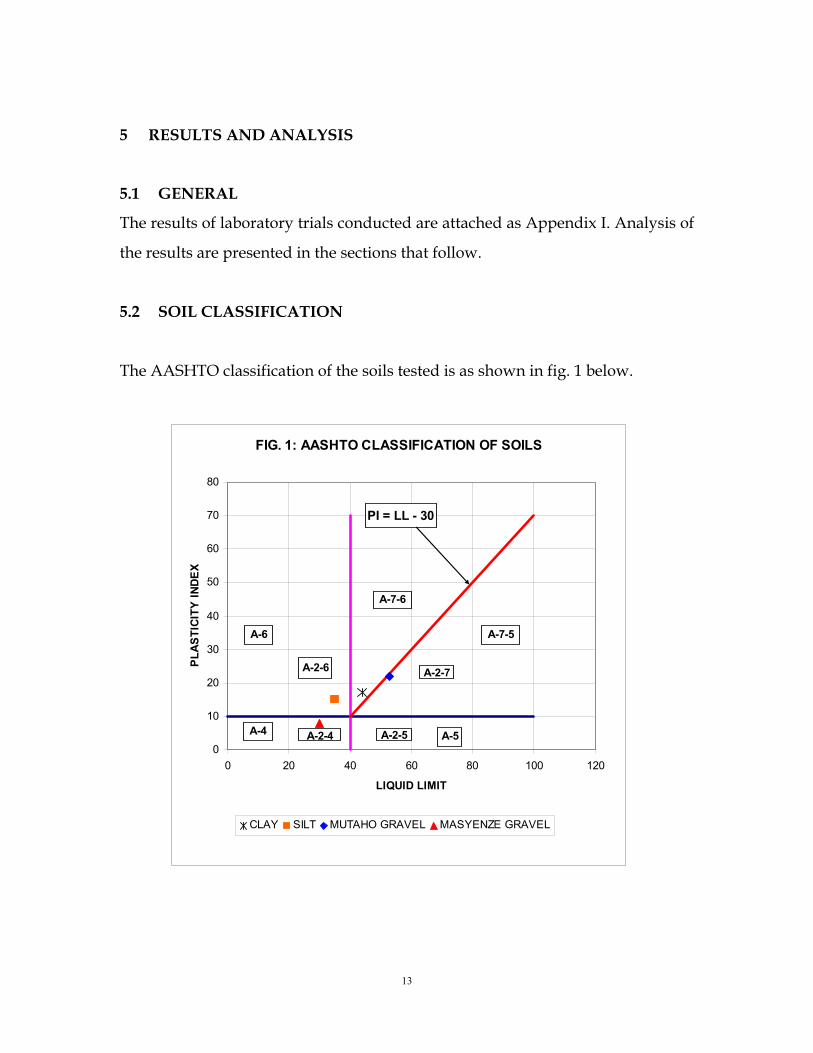
5.2 SOIL CLASSIFICATION
The AASHTO classification of the soils tested is as shown in fig. 1 below.
FIG. 1: AASHTO CLASSIFICATION OF SOILS
0
10
20
30
40
50
60
70
80
0 20 40 60 80 100 120
LIQUID LIMIT
PL
AS
TIC
ITY
IN
DE
X
CLAY SILT MUTAHO GRAVEL MASYENZE GRAVEL
A-7-6
A-7-5A-6
A-2-6
A-5A-4
A-2-7
A-2-5A-2-4
PI = LL - 30

14
5.3 SOIL STRENGTH – STABLIZER CONTENT RELATIONSHIPS
The effect of stabilizer content on the strength of the various soils is shown in the
charts below.
FIG. 2: CLAY UCS
0
0.1
0.2
0.3
0.4
0.5
0.6
0.7
0.8
0.9
0% 1% 2% 3% 4% 5% 6% 7%
STABILIZER CONTENT
UC
S (
MP
a)
HRB E3 (L) HRB E3 (P) CEM I
FIG. 3: SILT UCS
0
0.2
0.4
0.6
0.8
1
1.2
1.4
0% 1% 2% 3% 4% 5% 6% 7%
STABILIZER CONTENT
UC
S (
MP
a)
HRB E3 (L) HRB E3 (P) CEM I
FIG. 4: MUTAHO GRAVEL UCS
0
0.2
0.4
0.6
0.8
1
1.2
1.4
0% 1% 2% 3% 4% 5% 6% 7%
STABILIZER CONTENT
UC
S (
MP
a)
HRB E3 (L) HRB E3 (P) CEM I
FIG. 5: MASYENZE GRAVEL UCS
0
1
2
3
4
5
6
0% 1% 2% 3% 4% 5% 6% 7%
STABILIZER CONTENT
UC
S (
MP
a)
HRB E3 (L) HRB E3 (P) CEM I

15
5.4 SOIL PLASTICITY – STABLIZER CONTENT RELATIONSHIPS
The effect of stabilizer content on the plasticity of the various soils is shown in
the charts below.
FIG. 6: PLASTICITY INDICES (CLAY)
0
2
4
6
8
10
12
14
16
18
0% 2% 4% 6%
STABILIZER CONTENT
PL
AS
TIC
ITY
IND
EX
(%
HRB E3 (L) HRB E3 (P) CEM I
FIG. 7: PLASTICITY INDICES (SILT)
0
2
4
6
8
10
12
14
16
18
0% 2% 4% 6%
STABILIZER CONTENT
PL
AS
TIC
ITY
IN
DE
X (
%)
HRB E3 (L) HRB E3 (P) CEM I
FIG. 8: PLASTICITY INDICES (MUTAHO GRAVEL)
0
2
4
6
8
10
12
14
16
18
0% 2% 4% 6%
STABILIZER CONTENT
PL
AS
TIC
ITY
IN
DE
X (
%)
HRB E3 (L) HRB E3 (P) CEM I
FIG. 9: PLASTICITY INDICES (MASYENZE GRAVEL)
0
1
2
3
4
5
6
7
8
9
0% 2% 4% 6%
STABILIZER CONTENT
PL
AS
TIC
ITY
IN
DE
X (
%)
HRB E3 (L) HRB E3 (P) CEM I

16
6 CONCLUSIONS AND RECOMMENDATIONS
The following conclusions are drawn from analyses of foregoing results:
That for the HRB formulations tested are effective in enhancement of soil
strength, which is a key objective of stabilization;
That for the HRB formulations tested are effective in the reduction of soil
plasticity, which is a key objective of stabilization.
Following laboratory trials presented in this study, we recommend the conduct
of full-scale field trials to evaluate in-service performance of soils stabilized with
HRB. Such field trials would also evaluate the efficacy of mixing and compaction
methods with a view to develop works specifications for these materials.
We further recommend that these trials be conducted under the supervision of
the Materials Testing and Research Department of the MoTI on a wider variety
of soils countrywide.
17
7 REFERENCES
1. KNWA 2569-1:2014 Hydraulic road binders, Part 1: Rapid hardening
hydraulic road binders — Composition, specification and conformity
criteria
2 BS EN 13282-1:2013 Hydraulic road binders, Part 1: Rapid hardening
hydraulic road binders — Composition, specification and conformity
criteria
3 THE FRENCH ROAD ENGINEERING COMMITTEE -CFTR
(2007). Treatment of soils with lime and / or hydraulic binders
(application to the construction of pavement base layers). SETRA.
Paris, France.
4 THE FRENCH ROAD ENGINEERING COMMITTEE -CFTR
(2004). Treatment of soils with lime and / or hydraulic binders
(application to the construction of fills and capping layers). SETRA.
Paris, France.
5 HOWARD ROBINSON. Hydraulically Bound Materials. Tarmac,
BLA Seminar, 2007.
6 BRITISH STANDARDS INSITUTION (2004). Part 13: Soils treated
by hydraulic road binders. BS EN 14227, London, UK.
7 THE BRITISH IN-SITU CONCRETE PAVING ASSOCIATION
(2005). Draft: Code of Practice for the Design of Road Pavement. CSIR,
Pretoria, South Africa, for SATCC.
8 SOUTH AFRICAN TRANSPORT AND COMMUNICATION
COMMISSION – SATCC (1998). Technical Data Sheet: Cement
and other hydraulically Bound Mixtures. BRITPAVE, Surrey, UK.
9 NATIONAL COUNCIL FOR AIR AND STREAM
IMPROVEMENT (NCASI) .2003. Beneficial Use of Industrial By-
Products. Special Report, Washington, USA.
18
10 LAFARGE RESEARCH CENTER TEST REPORT. Kenya –
Evaluation of cements and HRB LCR-RES-249 - Version : 1. N.
Richard, Lafarge Research Center, Lyon, France

19
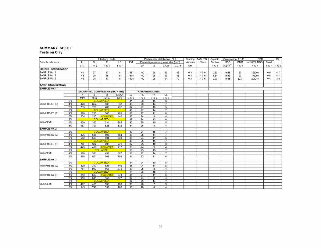
APPENDIX I : TEST RESULTS SUMMARIES
20
SUMMARY SHEETTests on Clay
Grading AASHTO Organic ICLSample reference LL PL PI LS PM Modulus Class Content MDD OMC at 100% MDD Swell
( % ) ( % ) ( % ) ( % ) 20 2 0.425 0.075 GM ( % ) ( kg/m3 ) ( % ) ( % ) ( % ) ( % )
Before Stabilization44 27 17 8 1581 100 98 93 83 0.3 A-7-6 0.60 1628 23 15(26) 0.5 4.743 25 18 8 1674 100 98 93 83 0.3 A-7-6 1.54 1633 23 17(26) 0.5 4.745 28 17 8 1598 100 98 94 79 0.3 A-7-6 0.90 1638 22.7 20(24) 0.4 3.8
After Stabilization
1 2 3 MEAN LL PL PI LSMPa MPa MPa MPa ( % ) ( % ) ( % ) ( % )
2% 41 26 15 84% 420 657 536 538 40 26 14 76% 735 729 409 732 37 27 10 52% 41 27 14 74% 398 215 580 489 38 27 11 66% 204 215 COLLAPSED 140 33 24 9 42% 37 24 13 64% 459 365 331 385 35 25 10 56% 967 707 823 832 34 26 8 4
2% 39 24 15 74% 425 525 503 484 39 25 14 76% 552 503 834 630 35 24 11 52% 40 25 15 74% 99 304 238 271 37 25 12 66% 425 409 COLLAPSED 417 33 24 9 42% 38 23 15 74% 398 331 431 387 36 22 14 76% 890 801 702 798 34 23 11 6
2% 34 24 10 54% 470 343 525 446 35 24 11 56% 751 912 663 775 33 25 8 42% 41 26 15 74% 243 503 COLLAPSED 373 35 24 11 66% 613 541 155 577 32 24 8 42% 37 23 14 74% 497 425 536 486 33 26 7 36% 945 796 558 766 36 28 8 4
SAMPLE No. 3
SAMPLE No. 1
With HRB E3 (L)
CBR
SAMPLE No. 1SAMPLE No. 2
Atterberg Limits Compaction T 180
With HRB E3 (L)
With CEM I
With HRB E3 (P)
COLLAPSED
With CEM I
SAMPLE No. 3
With CEM I
With HRB E3 (P)
SAMPLE No. 2
With HRB E3 (L)
With HRB E3 (P)
COLLAPSED
COLLAPSED
COLLAPSED
COLLAPSED
COLLAPSED
COLLAPSED
Particle size distribution ( % )Percentage passing sieve size (mm)
COLLAPSED
COLLAPSE
UNCONFINED COMPRESSION (7DC + 7DS) ATTERBERG LIMITS
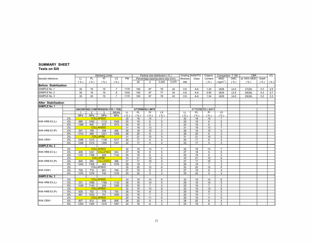
21
SUMMARY SHEETTests on Silt
Grading AASHTO Organic ICLSample reference LL PL PI LS PM Modulus Class Content MDD OMC at 100% MDD Swell
( % ) ( % ) ( % ) ( % ) 20 2 0.425 0.075 GM ( % ) ( kg/m3 ) ( % ) ( % ) ( % ) ( % )
Before Stabilization34 19 15 7 1170 100 97 78 44 0.8 A-6 1.24 1828 14.0 27(36) 0.3 2.9
35 19 16 8 1232 100 97 77 44 0.8 A-6 0.90 1829 13.9 30(36) 0.2 2.7
35 20 15 7 1170 100 97 78 43 0.8 A-6 1.54 1829 14.0 29(36) 0.2 3.3
After Stabilization
1 2 3 MEAN LL PL PI LS LL PL PI LSMPa MPa MPa MPa ( % ) ( % ) ( % ) ( % ) ( % ) ( % ) ( % ) ( % )
2% 32 18 14 7 32 18 14 74% 985 1050 1112 1049 25 19 6 5 25 19 6 56% 1398 845 972 1072 24 18 6 3 24 18 6 32% 31 18 13 7 31 18 13 74% 547 199 448 498 28 18 10 5 28 18 10 56% 1315 486 1221 1268 26 20 6 3 26 20 6 32% 31 21 10 5 31 21 10 54% 1298 1215 1138 1217 25 17 8 4 25 17 8 46% 1348 1315 1359 1341 22 17 5 3 22 17 5 3
2% 32 19 13 7 32 19 13 74% 409 1221 COLLAPSED 543 27 18 9 5 27 18 9 56% 1331 1166 928 1142 25 19 6 3 25 19 6 32% 33 21 12 6 33 21 12 64% 840 265 COLLAPSED 368 27 17 10 5 27 17 10 56% 1243 1309 403 1276 26 19 7 3 26 19 7 32% 32 20 12 6 32 20 12 64% 729 718 801 749 27 19 8 4 27 19 8 46% 1376 1376 740 1376 25 20 5 3 25 20 5 3
2% 33 19 14 6 33 19 14 64% 331 1099 1166 1133 28 18 10 5 28 18 10 56% 1436 1144 249 1290 25 18 7 3 25 18 7 32% 32 19 13 6 32 19 13 64% 635 702 779 705 28 19 9 5 28 19 9 56% 967 1033 751 1000 25 18 7 3 25 18 7 32% 29 18 11 6 29 18 11 64% 807 912 856 858 28 20 8 4 28 20 8 46% 1204 1354 1315 1291 24 18 6 3 24 18 6 3
Atterberg Limits Compaction T 180Particle size distribution ( % )
With HRB E3 (P)
With CEM I
SAMPLE No. 3
CBR
SAMPLE No. 1 UNCONFINED COMPRESSION (7DC + 7DS) ATTERBERG LIMITS
SAMPLE No. 1
SAMPLE No. 2
SAMPLE No. 3
ATTERBERG LIMITS
With HRB E3 (L)
With HRB E3 (P)
With CEM ICOLLAPSED
With HRB E3 (L)
With HRB E3 (P)
With CEM I
SAMPLE No. 2
With HRB E3 (L)
COLLAPSED
COLLAPSED
COLLAPSED
COLLAPSE
COLLAPSED
Percentage passing sieve size (mm)
COLLAPSE
COLLAPSED
COLLAPSED
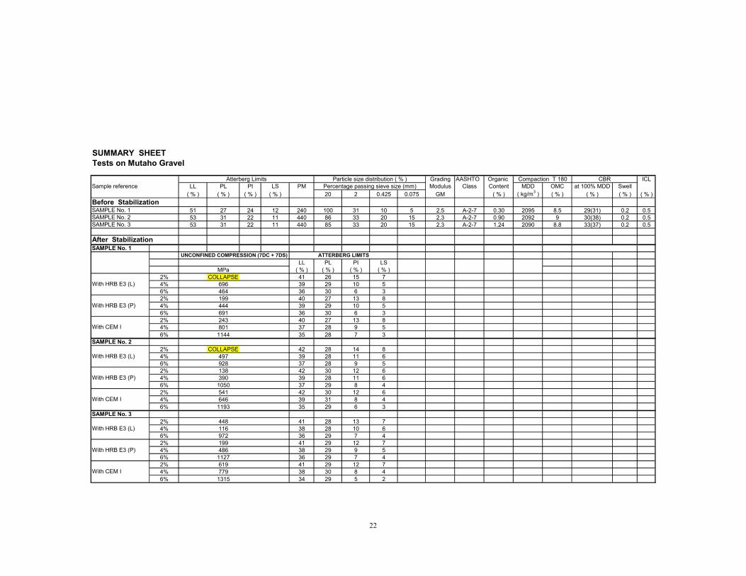
22
SUMMARY SHEETTests on Mutaho Gravel
Grading AASHTO Organic ICLSample reference LL PL PI LS PM Modulus Class Content MDD OMC at 100% MDD Swell
( % ) ( % ) ( % ) ( % ) 20 2 0.425 0.075 GM ( % ) ( kg/m3 ) ( % ) ( % ) ( % ) ( % )
Before Stabilization51 27 24 12 240 100 31 10 5 2.5 A-2-7 0.30 2095 8.5 29(31) 0.2 0.553 31 22 11 440 86 33 20 15 2.3 A-2-7 0.90 2092 9 30(38) 0.2 0.553 31 22 11 440 85 33 20 15 2.3 A-2-7 1.24 2090 8.8 33(37) 0.2 0.5
After Stabilization
LL PL PI LSMPa ( % ) ( % ) ( % ) ( % )
2% COLLAPSE 41 26 15 74% 696 39 29 10 56% 464 36 30 6 32% 199 40 27 13 84% 444 39 29 10 56% 691 36 30 6 32% 243 40 27 13 84% 801 37 28 9 56% 1144 35 28 7 3
2% COLLAPSE 42 28 14 84% 497 39 28 11 66% 928 37 28 9 52% 138 42 30 12 64% 390 39 28 11 66% 1050 37 29 8 42% 541 42 30 12 64% 646 39 31 8 46% 1193 35 29 6 3
2% 448 41 28 13 74% 116 38 28 10 66% 972 36 29 7 42% 199 41 29 12 74% 486 38 29 9 56% 1127 36 29 7 42% 619 41 29 12 74% 779 38 30 8 46% 1315 34 29 5 2
Atterberg Limits Compaction T 180Particle size distribution ( % )Percentage passing sieve size (mm)
CBR
SAMPLE No. 1 UNCONFINED COMPRESSION (7DC + 7DS) ATTERBERG LIMITS
SAMPLE No. 1SAMPLE No. 2SAMPLE No. 3
With HRB E3 (L)
With HRB E3 (P)
With CEM I
SAMPLE No. 3
With HRB E3 (L)
With HRB E3 (P)
With CEM I
SAMPLE No. 2
With HRB E3 (L)
With HRB E3 (P)
With CEM I

23
SUMMARY SHEETTests on Masyenze Gravel
Grading AASHTO Organic ICLSample reference LL PL PI LS PM Modulus Class Content MDD OMC at 100% MDD Swell
( % ) ( % ) ( % ) ( % ) 20 2 0.425 0.075 GM ( % ) ( kg/m3 ) ( % ) ( % ) ( % ) ( % )
Before Stabilization33 24 9 4 171 85 32 19 14 2.4 A-2-4 1.54 1990 13.4 40(46) 0.2 0.430 22 8 5 80 100 30 10 5 2.6 A-2-4 1.24 1992 13.5 42(47) 0.2 0.429 22 7 4 70 100 31 10 5 2.5 A-2-4 0.90 1990 13.6 40(46) 0.2 0.4
After Stabilization
LL PL PI LSMPa ( % ) ( % ) ( % ) ( % )
2% 856 26 20 6 44% 1254 246% 3591 222% 646 26 20 6 34% 1293 246% 3757 232% 983 27 22 5 34% 3315 246% 5249 21
2% 729 27 21 6 44% 611 246% 2762 212% 309 26 20 6 34% 956 246% 1359 222% 696 28 22 6 34% 1315 256% 4420 22
2% 238 28 21 7 44% 1392 266% 3204 242% 657 27 21 6 44% 1138 256% 2486 222% 967 27 21 6 34% 1657 256% 5249 23
NON-PLASTIC
NON-PLASTICNON-PLASTIC
NON-PLASTIC
NON-PLASTIC
NON-PLASTICNON-PLASTIC
NON-PLASTIC
NON-PLASTIC
NON-PLASTICNON-PLASTIC
NON-PLASTIC
Atterberg Limits Compaction T 180
NON-PLASTICNON-PLASTIC
NON-PLASTIC
Particle size distribution ( % )Percentage passing sieve size (mm)
CBR
SAMPLE No. 1 UNCONFINED COMPRESSION (7DC + 7DS) ATTERBERG LIMITS
SAMPLE No. 1SAMPLE No. 2SAMPLE No. 3
With HRB E3 (L)
With HRB E3 (P)
With CEM I
SAMPLE No. 2
With HRB E3 (L)
With HRB E3 (P)
With CEM I
SAMPLE No. 3
With HRB E3 (L)
With HRB E3 (P)
With CEM I
NON-PLASTIC
NON-PLASTICNON-PLASTIC

24
APPENDIX II : SAMPLE OF LAFARGE HYDRAULIC ROAD
BINDERS MANUFACTURED AND USED IN OTHER
COUNTRIES
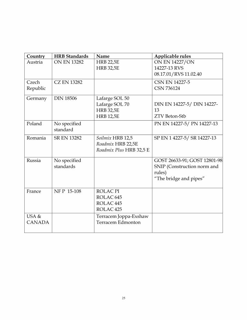
25
Country HRB Standards Name Applicable rules Austria ON EN 13282 HRB 22,5E
HRB 32,5E ON EN 14227/ON 14227-13 RVS 08.17.01/RVS 11.02.40
Czech Republic
CZ EN 13282 CSN EN 14227-5 CSN 736124
Germany DIN 18506 Lafarge SOL 50 Lafarge SOL 70 HRB 32,5E HRB 12,5E
DIN EN 14227-5/ DIN 14227-13 ZTV Beton-Stb
Poland No specified standard
PN EN 14227-5/ PN 14227-13
Romania SR EN 13282 Soilmix HRB 12,5 Roadmix HRB 22,5E Roadmix Plus HRB 32,5 E
SP EN 1 4227-5/ SR 14227-13
Russia No specified standards
GOST 26633-91; GOST 12801-98 SNIP (Construction norm and rules) “The bridge and pipes”
France NF P 15-108 ROLAC PI ROLAC 645 ROLAC 445 ROLAC 425
USA & CANADA
Terracem Joppa-Exshaw Terracem Edmonton