poseidon tsj 6-03.02 7 -...
TRANSCRIPT

1
Service Manual
Poseidon

A Technical Data
B Construction
C Function
D Trouble-shooting
E Service/Repair
F Adjustment/Test
G Wiring Diagrams
H Spare Parts Proposal
I Special Information
IndexPoseidon

Poseidon_GB01
Technical Data A
1
Poseidon 1200 Primary data Unit General Nominal values TolerancesVoltage VAC 200 240 400 415 440 440 +6/-10%Frequency Hz 50 50 50 50 60Motor couplingNumber of phases Pce. 3 3 3 3Power consumption A 12 +-1.5High voltage KV 2.4 in 2 sec.Leakage current mA 0.75Resistance in ground circuit Ohm 0.2Absorption power kW 6.7Axel power kW 5.5Revolutions Min-1 1440 1420-1470Control voltage VAC 200 240 400 415 440 440 +-10%Signal voltage microprocessor VAC 5 +-10%IP classification 45Bypass time auto start/stop Sec 20Bypass time manual Min 5Water volume, high-pressure l/min 17.6Water volume, low-pressure l/min 19.1Machine's pressure gauge Bar 175 +-8.5%Pump pressure, high-pressure Bar 158Pressure, h-p pump outlet Bar 152Opening pressure, pump outlet Bar 185 +-7Bypass pressure Bar 11 +-4Suction capacity Bar 0.17Suction height, primed m 3Max. water inlet temperature °C 85Max. water inlet pressure Bar 10Reaction force, max. N 54Acoustic pressure level dBA 75.4Oil volume Litre 0.5Oil type Pump oil 100

Poseidon_GB01
Technical Data A
2
Poseidon 1280 Primary data Unit General Nominal values TolerancesVoltage VAC 200 240 400 415 440 440 +6/-10%Frequency Hz 50 50 50 50 60Motor couplingNumber of phases Pce. 3 3 3 3Power consumption A 13 +-1.5High voltage KV 2.4 in 2 sec.Leakage current mA 0.75Resistance in ground circuit Ohm 0.2Absorption power kW 8.3Axel power kW 6.5Revolutions Min-1 1440 1420-1470Control voltage VAC 200 240 400 415 440 440 +-10%Signal voltage microprocessor VAC 5 +-10%IP classification 45Bypass time auto start/stop Sec. 20Bypass time manual Min 5Water volume, high-pressure l/min 18.6Water volume, low-pressure l/min 20.3Machine's pressure gauge Bar 195 +-8.5%Pump pressure, high-pressure Bar 178Pressure, h-p pump outlet Bar 170Opening pressure, pump outlet Bar 200 +-7Bypass pressure Bar 12 +-4Suction capacity Bar 0.17Suction height, primed m 3Max. water inlet temperature °C 85Max. water inlet pressure Bar 10Reaction force, max. NAcoustic pressure level dBA 75.4Oil volume Litre 0.5Oil type Alphasyn T 150

Poseidon_GB01
Technical Data A
3
Poseidon 720 Primary data Unit General Nominal values TolerancesVoltage VAC 230 +6/-10%Frequency Hz 50Motor coupling 3Number of phases Pce. 1Power consumption A 12 +-1.5High voltage KV 2.4 in 2 sec.Leakage current mA 0.75Resistance in ground circuit Ohm 0.2Absorption power kW 2.9Axel power kW 2.1Revolutions Min-1 1430 1420-1470Control voltage VAC 230 +-10%Signal voltage microprocessor VAC 5 +-10%IP classification 45Bypass time auto start/stop Sec 20Bypass time manual Min 5Water volume, high-pressure l/min 11.5Water volume, low-pressure l/min 12.5Machine's pressure gauge Bar 105 +-8.5%Pump pressure, high-pressure Bar 101Pressure, h-p pump outlet Bar 93Opening pressure, pump outlet Bar 125 +-7Bypass pressure Bar 10.5 +-4Suction capacity Bar 0.17Suction height, primed m 3Max. water inlet temperature °C 85Max. water inlet pressure Bar 10Reaction force, max. N 54Acoustic pressure level dBA 75.4Oil volume Litre 0.5Oil type Pump oil 100

1Poseidon_GB01
Construction BFrame
The frame is built of Ø25mm steel pipes. One nozzle can be stored on each side of the machine.
2, Ø250mm wheels and 1, Ø100mm swivel wheel are mounted to the frame.
A bent bar is attached to the front of the frame to protect hose attachments. The bar is also used for lifting themachine both manually and by crane.
The back bar is equipped with fixtures for mounting hose reel, a U-bar for placing nozzles, and winding reel forelectrical cable.The steering handle is made of plastic.
Cabinet
The cabinet is made of vacuum-shaped plastic.On the cabinet’s top side there is room for storing small auxiliary articles.All hoses are connected through the hole at the front of the cabinet.
Motor/pump
The motor/pump unit is attached to the frame with four taptite screws in the electric motor’s stator. Thisway the pump can be accessed from the front of the machine, and those parts of the pump susceptibleto wear are easily serviced.
The pump is a 4-cylinder axial piston pump with a wobble disc system and solid ceramic pistons. Suctionand pressure valves are made of stainless steel.
The oil system is closed, and the oil level can be checked through a liquid indicator on the side of thecabinet.
The pump’s water connection is mounted using ¾” quick-acting coupling.The pump’s pressure outlet is mounted with a 3/8” quick-acting couplingnipple.
The pump pressure can be read in bars (CPA) on an adapted pressure gauge.
Start/stop system
The machine’s start/stop system is controlled by a microprocessor that stops/interrupts the signal froma reed switch. The reed switch is activated by the flow of a magnetic piston mounted in the pump outlet’sflow control through the pump.
The start switch has 3 settings:
0 = Machine stopped.
I = Aut. start/stop. Machine stopped with automatic stop function if the spray handle is not activatedafter 20 seconds.
Man = Manuel. Machine started in manual position. The machine stops automatically, however, if thespray handle is not activated after 5 minutes.Use the manual position if the machine is set to suction without water inlet pressure.

2Poseidon_GB01
Construction B
Electrical system
The electrical system is located in electrical casing placed on the motor/pump unit.All automatic functions are controlled by a microprocessor built into a circuit board.
EquipmentThe machine’s standard equipment consists of:Ergo 3000 spray handle.10 mtr. Double wire high-pressure hose.Tornado nozzle.¾” quick coupling nipple.
Poseidon_GB01
Function C
1
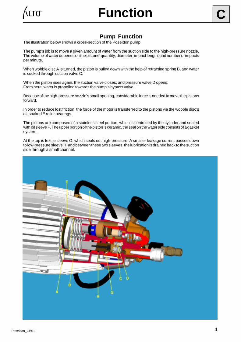
Pump FunctionThe illustration below shows a cross-section of the Poseidon pump.
The pump’s job is to move a given amount of water from the suction side to the high-pressure nozzle.The volume of water depends on the pistons’ quantity, diameter, impact length, and number of impactsper minute.
When wobble disc A is turned, the piston is pulled down with the help of retracting spring B, and wateris sucked through suction valve C.
When the piston rises again, the suction valve closes, and pressure valve D opens.From here, water is propelled towards the pump’s bypass valve.
Because of the high-pressure nozzle’s small opening, considerable force is needed to move the pistonsforward.
In order to reduce lost friction, the force of the motor is transferred to the pistons via the wobble disc’soil-soaked E roller bearings.
The pistons are composed of a stainless steel portion, which is controlled by the cylinder and sealedwith oil sleeve F. The upper portion of the piston is ceramic, the seal on the water side consists of a gasketsystem.
At the top is textile sleeve G, which seals out high-pressure. A smaller leakage current passes downto low-pressure sleeve H, and between these two sleeves, the lubrication is drained back to the suctionside through a small channel.

Poseidon_GB01
Function C
2
Bypass Valve Function
The bypass valve has 4 functions:1. Protect the machine against excess pressure.2. Relieve the pressure in bypass.3. Fast conversion to high-pressure.4. Ensure 0 pressure when the machine is stopped.
Operation:
The water from the pump is led into chamber A of the bypass valve.From there, the water passes through hole B in piston C and out of the machine.This leads to a pressure imbalance in piston C, which keeps valve disc D closed to valve seat E.
Bypass:
When water consumption stops (the spray handle is released), pressure increases briefly until safety valve Fopens upon reaching the pressure setting, which should be adjusted to 25-30 bars over working pressure. Thiscauses the pressure drop in piston C to disappear, and valve disc D moves from valve seat E. The machine isnow running in bypass.

Poseidon_GB01
Function C
3
� � � � � � � � � � � �
A
BB
C
D
E
F

Poseidon_GB01
Function C
4
� � � � � � � � � � � � � � �
F
A
B
C
B
E
D

Poseidon_GB01
Function C
5
Flow Control
Flow control consists of:
1. Casing2. Piston w/ magnet3. Spring4. Reed switch
Operation:
A drop in pressure in the piston pushes the piston forward, causing the magnet to activate the reed switch.A drop in pressure on the piston’s end face causes the piston to remain in this position.
Bypass:
When water is not being consumed, the drop in pressure in the piston stops, and the piston is pushed backby the spring, deactivating the reed switch.The pressure is balanced out through the hole in the piston, and the force of the spring holds the piston in aneutral position.
� � � � � �
� � � �
� � � � � �
� � � � � � �

Poseidon_GB01
Function C
6
PC Board
The circuit board has the following functions:1. To start the electric motor when starting the machine.2. To stop the electric motor when operation of the machine is finished.3. To record and store data concerning the machine’s work situations, operation, and bypass.
The circuit board is protected against excess pressure thanks to a circuit breaker (0.63A- SLOW) placed onthe board.
Start switch positions
0:The machine is not in operation; there is no power from the Start/Stop switch to print and the contactor’smagnetic pole.
1:The machine is set to automatic start/stop operation.
When you activate the spray handle and water is flowing through the machine, the flow sensor’s reed switchsignals the circuit board’s microprocessor, and the machine runs uninterrupted.
When you release the spray handle, and water flow through the machine stops, the signal to the PC board’smicroprocessor is interrupted. After a 20-second delay, power to the contactor’s magnetic pole is cut off, andthe electric motor stops.
Man:
The machine is set to manual operation.
The flow sensor is monitored via the reed switch but is not active.
The electric motor runs uninterrupted regardless of whether or not the reed switch registers water flow.
When you release the spray handle and the water flow through the machine stops, the power to the Start/Stopswitch and to the contactor’s magnetic pole is cut off after 5 minutes.The machine must then be restarted using the Start/Stop switch.
Service functions:
1. Identification of machine and software type.2. Read-out of number of starts.3. Read-out in hours/minutes of operating time under flow.4. Read-out in hours/minutes of bypass time.
These read-outs are made with ALTO SB Datalogger .
A description of SB Datalogger will be added later.

Poseidon_GB02
Trouble-shooting D
1
Poss. cause/ Check Circ
uit b
reak
ers
Con
tact
or +
coi
l
Ele
ctric
al c
onne
ctio
ns +
plu
g
Tem
pera
ture
sen
sor
in m
otor
Sta
rt s
witc
h
Prin
t + r
eed
switc
h
Pis
ton
for
bypa
ss v
alve
Pum
p pr
essu
re +
h-p
noz
zle
Suc
tion
valv
e +
sea
t
Pre
ssur
e va
lve
+ s
eat
Leak
s in
hos
es
Byp
ass
valv
e +
dis
c
O-r
ing
in c
ylin
der
head
Wat
er fi
lter
Pre
ssur
e sl
eeve
Air
in p
ump
Saf
ety
valv
e
Wat
er s
uppl
y
Wat
er te
mpe
ratu
re
Suc
tion
heig
ht
Suc
tion
cup
on b
ypas
s va
lve
Oil
slee
ve +
oil
hose
s
Suc
tion
slee
ve
Flo
w c
ontr
ol
Symptom:Motor doesn't start X X X X X X XMotor doesn't stop XMotor stops X X X X X XMax. pressure too high XMax. pressure too low X X X X X X X X X X X XMax. pressure irreg. in suction X X X X X X X XMax. pressure 50-70 bars X X XMax. pressure pulsating X X XBypass pressure too high X X XOil consumption too high XPump run only bypass X XBypass valve "thumps" X X XUneven pressure during operation X XPump doesn't go into bypass X X
Operating Requirements
To ensure error-free operation, the following requirements must be met:
1. Machine and equipment must be free of air and without leaks.
2. Water temperature must not exceed 85°C when inlet pressure on water supply.
3. In suction mode, water temperature must be significantly lower, depending on the suctionheight. Make sure the pump does not cavitate (water boils under vacuum).
4. Water quality must be free of impurities > 50 µ.
5. Water supply must be sufficient at all times.
6. Ambient temperature must not exceed 40°C.
7. Supply voltage must not vary by more than 6% of the given value.

1Poseidon_GB01
Service/Repair E
Safety valve
The safety valve’s factory setting for opening pressure = working pressure + 25 to +30 bars.Upon each service inspection the setting must be tested and, if necessary, adjusted.When mounting, affix ball and pressure plate to the spring with lubrication.The seat is screwed on using a 10mm socket wrench (no gasket required).Before testing with a pressure gauge, make sure that two threads are visible behind the locknut.
Warning: Before starting the pump, check that the test manometer valve is open. Close the valve slowly;pressure must never exceed 250 bars.
Pressure side
Suction side
10mm special wrenchno.: 1206754
6mm Allen wrench
�
�
���
� � � � � � � � � � � � �

2Poseidon_GB01
Service/Repair E
Valve cylinder head 1
������
Lubrication ductPressure valve seat
Suction valve seat
Nylon ring
Textile sleeve (hard)
Back-up ring
Rubber sleeve (soft)
Remove the suction valve seat using impact piercer no. 1216506.Press out the pressure valve using a 2 mm piercer.Check valve seats.Mount again with fingers.
Removal and mounting is done manually.Lubricate the large O ring with grease.

3Poseidon_GB01
Service/Repair E
Lock/back-up ring
Rubber sleeve secondary
Thrust collar
Back-up ring
Textile sleeve
Expansion/back-up ring
O-ring
Suction valve Pressure valve
O-ring
When mounting textile sleeves, use tool no.: 1220090.It helps to place the sleeves in a water bath 3-4 hours before mounting.Remember to blow through the lubrication ducts with compressed air.
Valve cylinder head 2
� � � � � �

4Poseidon_GB01
Service/Repair E
O-ring
Oil sleeve
Plate
Back-up ring
Torque: 37 Nm
Oil filling
Oil draining
Always replace secondary sleeves whenreplacing pressure sleeves.Check for free passage in the thrustcollar’s drainage holes.
Drain the oil by loosening the plug at the bottom of the cylinderblock.Loosen the 8 nuts evenly in consideration of the pressure fromthe piston springs.Use special head no. 1206762.Mount new O rings on stay bolts using tool no. 1206812.
When changing the oil, loosen the hose connection abovethe cylinder block.Oil (0.5 litres) is poured into the threaded hole.
Testing has shown that the pump does not consume oilduring normal operation.In other words, under normal circumstances you do notneed to refill oil in the pump.Nevertheless, the oil level and quality must be checkedregularly through the liquid indicator.
Cylinder block 1

5Poseidon_GB01
Service/Repair E
Oil sleeve Low-pressure High-pressure
Contact surface Stainless steel Ceramic
Inspect the piston forwear on the contactsurface and in thearea for oil sleeves.Examine the ceramicfor cracks, and wipeclean any deposits.
Cylinder block 2
Carefully lift the oilsleeves out with asuitable screwdriver anddispose of them.Be careful not to scrapethe surface.
Before inserting the newsleeves, it is a good ideato moisten the sleeveswith soapy water.Insert new oil sleevesusing piercer no.1220429.
Gently tap or press in.

6Poseidon_GB01
Service/Repair E
Motor / wobble disc 1
The motor consists of a stator with windings, a rotor with an axel that is held in place with a bearing inthe N-bearing cover and the wobble disc’s innermost needle bearing in the D-bearing cover.Ventilator 4 is pressed onto the rotor over locking bush 5 and is mounted with two screws.The wobble disc’s pressure plate 23 is held in place with peg 22. Plate 21 ensures that needle bearing24 is held apart from oil sleeve X.
Remove locking ring 27.The wobble disc is easily removed withwheel dresser no. 1205715 and specialleg no.1206150/1206168.Remember to remove parallel key 17 beforeremoving D-bearing cover.Check bearing surfaces for wear.If in doubt, replace set 28 completely.
� � �
�
� � � �
�� �
� �
� �
23

7Poseidon_GB01
Service/Repair E
Motor / wobble disc 2
When mounting complete D bearing cover,protect the oil sleeve using tool no. 1206598,and place it on the axel before mounting
272625
24
30
3132
No. 26 No. 32
When mounting the wobble disc, lubricate the bearings with oil. The large roller bearings 25 and 31 areidentical. Remember to place locking ring 27 on the axel.
Inspect the bearing surfaces for wear. As long as there is only regular wear without holes or ridges, as in thepictures above, the wobble disc can be used again.

1Poseidon_GB01
Adjustment/Test F
Adjustment of reed switch
Place the reed switch in the plastic case with the screw loose enough so that the switch can still be movedback and forth.Place the reed switch as far forward in the direction of the water outlet as possible.Start the machine on setting 1, without a water connection.After approx. 20 seconds, the machine stops, and you can then adjust the reed switch.Slowly push the reed switch back until the machine starts.Next pull the reed switch approx. 3 mm away from the machine, and tighten the screw in the plasticcasing.Finally, test the start/stop function with a water connection to the machine.
This adjustment can also be made with an ohmmeter. In that case, remember to disconnect the machinefrom the power source.
� � � � � � � �
� � � � � � �
2Poseidon_GB01
Adjustment/Test F
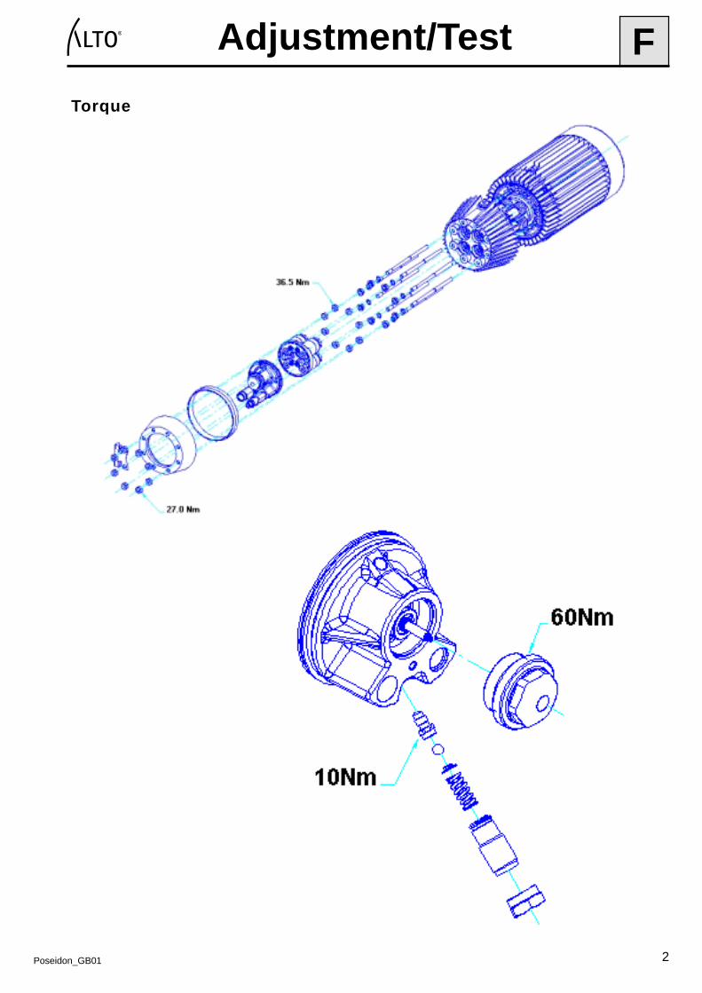
Torque

1P
oseidon_GB
01
Wirin
g D
iagram
sG
� � � � � � � � � � � � � � � � � � � � � � � � �
� �
� �
� �
� �
� �
� �
� � � � �
� � �
� � � � � � � � � � � � �
� � � � � � � � � � � � ! " � � �
# " � � � � � ! " � � � � � $ � � � � �
� ! " � � � %
� � � � � $ � � "
& � � " � ! " � � � � �
� � � � � � � � ! ' � �
� � � � � � ' � � � � �
( � � � � � � $ ) ( �
* � � $ � � � � � �
# " � � � � � $ � � � ! " $ � � � � �
� � � � � $ � � "
+ � � � � , $ � � � ! "
� � � � � $ ! � � � � ! � � �
( � � � � ! � � �
( � � ! � � � � � � � � � $ � � � � � � � �
- � . � / �
� �
/ �
� 0
�
� �� �
� �
� � �
� � �
� � �� ���
� �. �- �
1 �
1 �
1 �
2
� �
� �
� �
� �
� .
� � � .
� � � .
� ! " 3 � %* � � � � ! ' � � �
� � �
�
) � � � � � � �
� �
� �� � �
� �
� �
� �
�
�� �� ��
��
�
� �� �
� ��
�
� �
� �
�
�
� �
� �
� ! " � � %
� � � � �
� � � �
� � � ! '
� � � �
� � � �
) 4
5 � � 6
� � % 7
� � � 7
) � � � ! " �� � 7 � 7 � �
8 � 9 � � � � � & � � � � : � � � & � � � � : � � �; � � ! " � 7 < : � 7 =
� � � � � � 7
> � � �
�� � % 7
) � � ? � ' � � � % 7
� � " $ � � � � �
) � � � � 9 � �
+

2P
oseidon_GB
01
Wirin
g D
iagram
sG
� � � � � � � � � � � � � � � � � � � � � � � � �
�
� �
� �
� �
� �
+ �
� �
� �
�
�
2
* � � � � ! ' � � �� � �
�
) � � � � � � �
� � � ��
� �
�� �� ��
� �
� �
� �
� �
� .
� � � .
� � � .
� ! " 3 � %
� �
� � � � �
� �
� �
� �
�
��
�
� �� �
� ��
�
� �� �
� �
� � �
� � ����
- � . � / �
� �
/ �
� 0
�
�
� �. �- �
� �� � � �
� � � � � � � �
1 �
1 �
1 �
) 4
� �
� �
� �
� �
� �
� � � � � � � � � � � � �
� � � � � � � � � � � � ! " � � �
# " � � � � � ! " � � � � � $ � � � � �
� ! " � � � %
� � � � � $ � � "
( � � � � � � $ ) ( �
* � � $ � � � � � �
# " � � � � � $ � � � ! " $ � � � � �
� � � � � $ � � "
( � � � � ! � � �
� � & � � " � ! " � � � � � + � � � � , $ � � � ! "
+ � / � 9 � � � � � � 9 + � � � � � � �
� � � � � � � < & � � � � ! ' < � ! " � � � � � � � � � < � � � � � � � � $ � � � ! "
� � � � �
� � �
� � � � � � � � ! ' � �
� � � � � � ' � � � � �
� � � � � $ ! � � � � ! � � �
( � � ! � � � � � � � � � $ � � � � � � � �
�
� �
� �
� ! " � � %
� � � � �
� � � �
� � � ! '
� � � �
� � � �
�
� �
� �
; � � ! " � � � � $ � ! " � � � � � � � � � � � � � $ � � � � �
& � � � � � $ � � � ! " $ � � � � � � � � $ � � � �
5 � � 6
� � % 7
� � � 7
) � � � ! " �� 7 � � 7 � �
8 � 9 � � � � � & � � � � : � � � & � � � � : � � �; � � ! " � 7 < : � 7 = � � � � � 7
> � � �
�� � % 7
) � � ? � ' � � � % 7
� � " $ � � � ! " � � � � � �
) � � � � 9 � �
+
3P
oseidon_GB
01
Wirin
g D
iagram
sG
� � � � � � � � � � � � � � � � � � � � � � � � �
� �
� �
��
�
� �� �
� ��
�
) @
:
� � � �
� �
- � ; �
; �
� 0
�
� �- �
� � �
� � ��� �� �
� � �
� � �� � �
� �
� �
� �
� � � � � � � � � � � � �
� � � � � � � � � � � � ! " � � �
# " � � � � � ! " � � � � � $ � � � � �
( � � � � � � $ ) ( �
* � � $ � � � � � �
# " � � � � � $ � � � ! " $ � � � � �
( �
� �
) 4
� � � .
�
) � � � � � � �
� �
2
� � � � �
� �
� � � ! " 3 � % * � � � � ! ' � � �
� � � �� �� ��
� �
� � � � � .
� � � .
( �
� � � � � � � � ' � � 9 � � � � � � � � � � � � � � � � $ ! � � � ! � � � �
5 � � 6
� �
� �
� �
� ! " � � � %
� � � � � $ � � "
& � � " � ! " � � � � �
� � � � � $ � � "
+ � � � � , $ � � � ! "
( � � � � ! � � �
� � � � � � � � � � � � � ! ' � � � � � � � $ ! � � � � ! � � �
� � �
� � � � � �
( � � ! � � � � � � � � � $ � � � � � � � �
# � � � � � � � $ � � � � �
� � � � � � ' � � � � �
+ � � " � � ' � � � � �
� � % 7
� � � 7
) � � � ! " �� � 7 � � 7 � �
8 � 9 � � � � � & � � � � : � � � & � � � � : � � � ; � � ! " � 7 < : � 7 =
� � � � � � 7
> � � �
�� � % 7
) � � ? � ' � � � % 7
� � " $ $ � � � � 9 � � 9
) � � � � 9 � �
+

1Poseidon_GB01
Spare Parts Proposal H
� �� �� ��
� �� �� �
� $
� $
� $
$ �
! !! ! �
� �� �� �!
$ �
� " � ! ! ! � � !
� " � ! ! ! � � �
" � ! ! ! � � �
! � � � � �
� ! � � � � �
� � � ! ! � �
� � � � � � �
� ! � � � ! �
� � � ! � � �
! � � ! � � � � �

2Poseidon_GB01
Spare Parts Proposal H
� � � ! ! �
! � ! ! ! � ! �
! !! �� ��
! ! ! � � ! �
� ! � � � !
! � � � � �
! � ! ! ! � ! !
� !� � ��
� ! � ! � � !
� � � ! � ! �
� � � !
� � � ! � � �
� ! � ! � � �

3Poseidon_GB01
Spare Parts Proposal H
� � � � � � �
� ! � � � ! !
� !� !� ��
� � � � � ! �
� � � � � � �
� � � � � � �
! � � � � ! !
! � � ! � � � � �
� � � � � ! �
� ! � ! � �
� " � ! ! ! � � �
" � ! ! ! � � �
$ �