portfolio
DESCRIPTION
Portfolio of experienceTRANSCRIPT

E m i l y K r i e g e r
1 2 6 0 W e l s f o r d C t . , D a y t o n , O H 4 5 4 5 96 1 6 . 5 8 1 . 1 1 9 5 K R I E G E E Y @ G M A I L . C O M
Portfolio of Work
University of CincinnatiCollege of Design Architecture Art and PlanningSchool of Architecture and Interior DesignMaster of Architecture, Class of 2011Minor of Sustaining the Urban Environment
STUDIO WORKSPIRITUALITY’S RELEASE
URBAN HOUSINGKADIKOY FERRY STATION
SARDINIA SPRAWLCOMMUNITY BOOKS
CRANBROOK SPA
SUPPLEMENTAL SKILLSHAND RENDERING
ABSTRACT PAINTINGFIELD SKETCHINGPHOTOGRAPHY
A MOMENT IN DAAP
PROFESSIONAL WORKDAYTON BLOOD CENTER
KROCK CENTERHEALDSBURG
FASHION ISLAND ATRIUMAMERICAN EAGLE
07
SARDINIA SPRAWL
SARDINIA, ITALY
URBAN PLANNING
MINIMIZING URBAN SPRAWL
SUMMER 2008
While studying abroad in Italy, I partici-pated in a 10 day summer program on the Island of Sardinia focusing on ur-ban planning. Our project was to take a low-density site and give it a sustain-able city center and minimize urban sprawl. We found that the problems on our site were a poor urban nucle-us, lack of urban services, constantly changing population, low density, and mobility, while the opportunities were environmental sources, sea, pine and juniper trees, low density, agricultural areas, wind, good climate, good infra-structure, and minimal urban traffic.
The driving concept of the master plan was to create a better quality of life for the site while keeping it low density. The driving idea of our design is the “green corridor” concept. These corridors are environmental corridors that act as public spaces with multifunctional ac-tivities. These corridors follow the in-frastructure that moves people from one city to the next. Along with creat-ing public spaces the green corridors act as boundaries. Within these corri-dors “fingers” exist that hold the public spaces and multifunctional activities.
Caroline Bohlen
Carlo Chelo
Emily Krieger
Becca Kundysek
Manuela Porceddu
Jeffrey Rengering
Rosario Romano
Roberto Sussarello
Rodrigo Velazquez Bernabeu
Professor:
G. Maciocco
The image on the top left is a diagram of the existing conditions of the site that as a group we felt were important. The diagram on the bottom left is a conceptual master plan of our project. This is where we first started to incorpo-rate the different layer opportunities together.
A n a l y s i s :Our group started by identifying the problems and opportunities that existed within our site. We found that the problems were a poor urban nucleus, lack of urban services, social problems and disease, poverty of tourist services, constant-ly changing population, low density, poverty of house morphology, and mobility. The opportunities that we found to be evident were environmental sources, sea, pine and juniper trees, low density, agricultural areas, wind, good climate, good in-frastructure, and minimal urban traffic. Our group then decided to split up the existing conditions of the site into “layers” and analyzing the layers in-dividually. The five layers that we analyzed were water, vegetation, history and urban settlements, infrastructure, and topography. In our analysis we found that the vegetation that existed on the site was mostly pine, juniper, and agricultural land. Through our research we found that neither the pine or the juniper were natural to the site. In-stead they had been brought in to protect the dunes from erosion. to be respected or preserved.
After determined the opportunities that existed with-in the site we created a master plan that incorpo-rated all of the opportunities. The driving concept of the master plan was to create a better quality of life for the site while keeping it low density. The driving idea of our design is the “green corridor” concept. These corridors are environmental corri-dors that act as public spaces with multifunctional activities. The property lines, existing housing, and sprawl within the site determined the boundaries of the corridors. These corridors follow the infra-structure that moves people from one city to the next. Along with creating public spaces the green corridors act as boundaries. Within these cor-ridors “fingers” exist that hold the public spaces and multifunctional activities. This way residents no longer need to travel into the city for every day needs. No housing is allowed in the “fingers” which therefore also act as boundaries to the sprawl.
After we determined the opportunities that exist-ed within the site we created a master plan that incorporated all of the opportunities. The driv-ing concept of the master plan was to create a better quality of life for the site while keeping it low density. The driving idea of our design is the “green corridor” concept. These corridors are environmental corridors that act as public spaces with multifunctional activities. The prop-erty lines, existing housing, and sprawl within the site determined the boundaries of the corridors.
distribuzione insediativa: infrastrutture per chi?urban distribution: infrastructures for who?
The image above is a diagram of the infra-structure within the site. The diagram shows the major cities, direction of traffic along with the different types of traffic allowed to pass.
These corridors follow the infrastructure that moves people from one city to the next. Along with creating public spaces the green corridors act as boundaries. Within these corridors “fingers” exist that hold the public spaces and multifunctional activities. This way residents no longer need to travel into the city for ev-ery day needs. No housing is allowed in the “fingers” which therefore also act as boundaries to the sprawl.
We used the infrastructure to create sustainable transportation. Where different roads meet the type of transportation allowed through changes. The roads closest to the water are strictly pedestrian and bicycle traffic. As one moves outward scoot-ers, electric car, and full size vehicles are eventually added. Along the entire road multi level pathways exist for pedestrians and bicycles to travel on. These boardwalks continued out into the water connecting the coast with the sprawl. The “fingers” in this area transform into centers for tourists to use with the final “finger” being the boardwalk that continues into the water. Each “finger” holds multifunctional spaces and buildings. The boardwalk acts as a seamless connection between the water, the dunes, the pond, the vegetation, and the urban settlements.
1.
2. 3.
GRAPHIC ANALYSIS OF PROBLEM AREASCONCEPTUAL SITE PLANGRAPHICAL ANALYSIS OF SPRAWL LOCATIONS
1.
2.3.


Table of Contents
01 PROFESSIONAL EXPERIENCE DaytonVAMCRenovateRehab AmericanEagleOutfitters LexingtonVAMC5thFloorAddition JeffersonComplex DaytonDragonsStadiumImprovements RayandJoanKrocCommunityCenter02 ACADEMIC EXPERIENCE FutureformsforHealthyDevelopment LearningLaboratory TensionandRelaxation CranbrookAcademySpa SardiniaSprawl03 SUPPLEMENTAL SKILLS PhysicalModeling PhotoshopRendering HandRendering FieldSketching


Professional Experience

1.

RC
CT DT DT TG
RS
KB
SB
NRNR
TT
SL
SL
TT
TT
SL
SO
TM
TT
PB
TT
MT
TT
ST
TT
TT
TC TC TC
TC TC TC TC
FC FC FC FC
FC
FC
FC
FC
FCTC
TC
TC
TC TC
TC TC
TC
TC
LC
PS
PR
LC
LC
FC FC
FC
FC
FC
FC
FC
FC
BC
Chiropractor2C101
Exam Room2C100C
Exam Room2C100B
Exam Room2C100A
TreatmentFloor
2C100
Toilet2C100H
RehabilitationStorage2C100E
Linen Closet2C100D
Admin. Office2C131
Office2C100F
Locker Room2C100G
AL
WR
A601J3
A601J4
N Scale: 1/4" = 1'-0"
New Plan
EQUIPMENT SCHEDULE
Tag
Description Cou
nt
Supp
lier /
Inst
alle
r
2C100Treatment Floor
20DT Decompression Table 2 VVKB Kore Balance 1 VVLC Linen Cart 3 VVMT Mat Table 1 VVNR Nustep Recumbant 2 VVPB Parallel Bars 1 VVRS Recumbant Stepper 1 VVSB Stationary Bike 1 VVSO Scifit Orgometer 1 VVST Stairs 1 VVTG Total Gym 1 VVTM Treadmill 1 VVTT Treatment Table 5 VVWR Weight Rack 1 VV
2C100AExam Room
4SL Stool 1 VVTT Treatment Table 1 VV
2C100BExam Room
4SL Stool 1 VVTT Treatment Table 1 VV
2C100CExam Room
8SL Stool 1 VVTT Treatment Table 1 VV
2C100DLinen ClosetAL Alex Automated Linen 1 VV
2C100FOfficeFC Flipper Cabinet 18 VVPR Printer 1 VVPS Paper Shredder Box 1 VVTC Task Chair 10 VV
2C101Chiropractor
4CT Chiropractor Table 1 VVFC Flipper Cabinet 4 VVRC Recliner 1 VVTC Task Chair 1 VV
2C131Admin. OfficeBC Business Center 1 VVFC Flipper Cabinet 8 VVTC Task Chair 5 VV
EQUIPMENT LEGENDCC Contractor Furnished, Contractor InstalledCF Owner Furnished, Contractor InstalledVV Owner Furnished, Owner Installed
GENERAL EQUIPMENT NOTESA. Furniture and Equipment sizes and locations are for reference only.
Final plan to be provided by Owner.
PROGRESS PRINTNOT FOR CONSTRUCTION
JOHN POE ARCHITECTS
Drawing Title
Approved: Project Director
Location
Building Number
Project Title
Checked DrawnDate
Project No.
Drawing Number
Dwg. of
one-
eighth inch = one foot
one-
quarter inch =
one foot
three-
eighths inch =
one foot
one-
half inch =
one foot
three-
quarters inch = one
foot
one inch =
one foot
one and one-
half inches =
one foot
three inches =
one foot
04
816
00
00
00
04
44
86
66
61
22
FE
DC
BA
1 2 3 4 5 6 7 8 9
1 2 3 4 5 6 7 8 9
FE
DC
BA
A R C H I T E C T SJ O H N P O E
116 EAST THIRDSTREETDAYTON, OHIO 45402-2130
VA Project No.ARCHITECT/ENGINEERS:CONSULTANTS:
Office ofConstructionand FacilitiesManagement
JPA Project No.
937 461 3290 PHONE937 461 0260 [email protected]
99% OWNER REVIEW - NOT FOR CONSTRUCTION
9/21/2012 11:44:29 AM
Renovate Rehab DepartmentB330
9/21/12
EQUIPMENT PLAN
IF101KGTH
12010.00552-13-101
Dayton, Ohio330
Revisions Date
Renovate RehabDayton Veterans Affairs Medical CenterFederal / Health CareJohn poe ArchitectsWinter 2012
This project was a renovation of the physical rehab department in themainhospital at the Dayton VAMC. The renovation included a new therapy floor,examrooms,offices,andadministrationspaces.Thedesignintentwastocreateamorewelcoming,aswellasfunctional,spaceforthedialysispatients.Veryspecificphasingwasrequiredastheentiredepartmentneededtobecompletelyfunctionalthroughouttheentireconstructionprocess.
MyresponsibilitiesincludedworkingwithaProjectManageronschematicdesign,creatingdesignandconstructiondrawings,developingdetails,maintainingtheBIMmodel,interactingwithclients,andpreparingpresentationrenderings.
REFLECTED CEILING PLAN LEGEND
Recesseddownlight fixture Supply Air Diffuser
Return Air Grille2' x 4' fluorescentfixture
2' x 2' acousticaltile ceiling
Gypsum board / portlandcement plaster ceiling /soffit - painted
Pendant light fixture
Chain-hung light fixture
Access panel
Recessed wall-washfixture
Surface-mounted striplight fixture
2C101
2C100C
2C100B
2C100A
2C100
2C100H
2C100E
2C100D
2C131
2 22
2
2
2
1
1
1
1
3
3
3
10' - 0"
8' - 0"
8' - 0"
2A121
3A121
2A121
SIM
4
4' - 8 1/4" 4' - 8 1/8"9' - 8"
7' -
6 3/
4"21
' - 4
"
5
R15
' -3
1/4"
1
R20
' -8
1/4"
R 16' - 2"
8' - 0"
R16
' -2
1/4"
R24' - 9
1/2"
R24
' -9
3/4"
2A121
SIM
2A121
SIM
2A121
SIM 11' -
0"
8' - 0"
2 1
2A121
SIM
1' - 0" 1' - 0"
14
14
S2.1
S2.1
S2.1
S2.1
F F
S1.1
4A121
16
1"1' -
0"
6"
1' - 0"1
2
6
7
7
8 SEE PLAN
SEE PLAN
9
A6017
7/8"
9
10 11
12
137
9
715
GENERAL NOTESA. All wood blocking shall be fire retardant.B. Light fixtures, sprinkler heads, speakers, and HVAC devices shall be
located as close as possible to the center of acoustical ceiling panels.Confirm any deviation from this with the Project Engineer.
C. See P, M, E and FP drawings for additional information regarding finalinformation and quantites of fixtures/devices to be installed in ceiling.
D. See Electrical Drawings for lighting specifications.F. Ceiling height to be 9'-0" AFF, unless noted otherwise.
CEILING NOTES
Scale: 1/4" = 1'-0"1 REFLECTED CEILING PLAN
1 6" ACT grid edge trim.2 3-5/8" stud wall suspended from deck above with diagonal kicker
@8'-0"O.C. damaged fire proofing.3 Flexible cubicle curtain track.4 Overhead coiling counter door.5 Salvaged 'Solo Track' patient support track. See Detail 4/A121.6 Hanger wire.7 Acoustical ceiling tile.8 Cove light fixture.9 Existing composite concrete/metal deck.10 Existing structure with spray on fire proofing.11 Patient lift track furnished and installed by Owner's seperate contract.12 Semi-recessed patient lift track furnished and installed by Owner's
seperate contract. Contractor to coordinate installation with work underthis contract.
13 Patient lift cross track.14 Rework existing grid as needed15 Salvaged 'Solo Track' patient support track.16 X-Y patient lift assembly furnished and installed by Owner. Coordinate
all ceiling and above ceiling work with lift installer.
Scale: 1/2" = 1'-0"2 SECTION
Scale: 1/2" = 1'-0"3 SECTION
PROGRESS PRINTNOT FOR CONSTRUCTION
JOHN POE ARCHITECTS
Drawing Title
Approved: Project Director
Location
Building Number
Project Title
Checked DrawnDate
Project No.
Drawing Number
Dwg. of
one-
eighth inch = one foot
one-
quarter inch =
one foot
three-
eighths inch =
one foot
one-
half inch =
one foot
three-
quarters inch = one
foot
one inch =
one foot
one and one-
half inches =
one foot
three inches =
one foot
04
816
00
00
00
04
44
86
66
61
22
FE
DC
BA
1 2 3 4 5 6 7 8 9
1 2 3 4 5 6 7 8 9
FE
DC
BA
A R C H I T E C T SJ O H N P O E
116 EAST THIRDSTREETDAYTON, OHIO 45402-2130
VA Project No.ARCHITECT/ENGINEERS:CONSULTANTS:
Office ofConstructionand FacilitiesManagement
JPA Project No.
937 461 3290 PHONE937 461 0260 [email protected]
99% OWNER REVIEW - NOT FOR CONSTRUCTION
9/21/2012 11:36:55 AM
Renovate Rehab DepartmentB330
9/21/12
REFLECTED CEILING PLAN
A121KGTH
12010.00552-13-101
Dayton, Ohio330
Revisions Date
Scale: 1/2" = 1'-0"4 SECTION
1. Rendering of Therapy Floor2. Rendering of Nurse Station3. Detail of Cove Lighting4. Rendering of Therapy Floor
2.
4.
3.

1.1.

1. Photograph of Jean’s Department2. Rendering of Aerie Department3. Rendering of Jean’s Department4. Rendering of Entrance5. Photograph of Men’s Department6. Photograph of Main Entrance
American Eagle OutfittersNew York City, Times SquareRetailBAR ArchitectsWinter 2009
IwasanactivememberonaretailprojectteamworkingonaflagshipAmericanEagleOutfitterslocatedinTimesSquare,NewYorkCity.Alongwithmaintaininga3-Dmodelforcompany,client,andmarketinguses,Ialsoworkedwiththedesignteamduringthedesigndevelopmentphaseto create details, choosematerials, design fixtures and signage, anddevelopdesignschemes.
2. 3. 4.5. 6.
6.
5.

DN
DN UP
D
E
F
G
H
J
K
2 3 4 5 6 7 8 10
HealthAdministration
508
Mechanical500A
Vestibule500B
Stair #8ST-8
ChiefAmbulatory
Care501
CentralSchedulingSupervisor
502
Chief HIMS503
ConferenceRoom504 Family
Restroom506HAC
505
Copy Room507
ADPAC512
Asst. ChiefHAS511
Secretary510
Chief HAS509
Corridor513
Mens Toilet569
WomensToilet568 Conference
577
Side Waiting579
Waiting578
Corridor586
PassengerElevatorEL-P6
PassengerElevatorEL-P7
Closet585
Elec Closet584
Stair #9ST-9
Closet583
ConferenceRoom582
Disclosure581
Tech Closet580
ProgramSupport Asst.
552
NurseExecutive
551
NurseExecutive
550
Admin.Officer
549
ProgramSupport Asst.
548Admin.Officer
547Medical Staff
546Medical Staff
545
Asst. Chief ofStaff544
Assoc. Dir.Patient Care
Serv.543
Chief of Staff542
Workroom541Director
540
Asst. Director538
Staff Asst. toAsst. Dir
534
Staff Asst. toDir.533
Chief Quality532
Mngr. Risk530
Fee Basis529
Staff Lounge527
Corridor531A
Quality531B
PatientSafety Officer
535
Mngr.Utilization
536Admin.Support
528 NurseAccredidation
537
Administrative563
Elec Closet573
Copy Room572
Public AffairsOfficer
574Mang. Asst.
571
PrivacyOfficer
564
Chief Fiscal565
HumanResources
570Storage
575Vestibule
576
Chief HR566
VERACoordinator
567
Project Engs.514
Chief Eng.515
Fire Safety516
IndustrialHygenist
517
Copy518
IT519
ServiceElevatorEL-S7
ServiceElevatorEL-S6
ServiceElevatorLobby520
ElectricCloset
521
Stair #7ST-7
Storage523
Conference525
EngineeringReception
524
1
Storage553
Cubicle554
Cubicle555
Copy Room558
Fee Nurse559
Fee Nurse560
SupportCubicle
562
NursingServices
557
Classroom561
Toilet539
2
2
1
3
3
3
3
4
45
5
5
7
8
98
8
7
8
7
8
7
Kitchen531C
10
11
12
5
10
12 11
13
14
10
11
12
5
5
5
10
15
16
1012
11
16
17
10
11
19
18
19
PROGRESS PRINTNOT FOR CONSTRUCTION
RDC/ JOHN POE ARCHITECTS
Drawing Title
Approved: Project Director
Location
Building Number
Project Title
Checked DrawnDate
Project No.
Drawing Number
Dwg. of
one-
eighth inch = one foot
one-
quarter inch =
one foot
three-
eighths inch =
one foot
one-
half inch =
one foot
three-
quarters inch = one foot
one inch =
one foot
one and one-
half inches =
one foot
three inches =
one foot
04
816
00
00
00
04
44
86
66
61
22
FE
DC
BA
1 2 3 4 5 6 7 8 9
1 2 3 4 5 6 7 8 9
FE
DC
BA
A R C H I T E C T SJ O H N P O E
800 362 1523 [email protected]
VA Project No.RDC/JPA Project No.
ARCHITECT/ENGINEERS:CONSULTANTS:
Office ofConstructionand FacilitiesManagement
XX
RDC /
524 FERNWOOD DRIVEALTAMONTE SPRINGS, FLORIDA32701
95% OWNER REVIEW - NOT FOR CONSTRUCTION
7/23/2012 5:39:36 PM
5th FLOOR MAIN ADDITION
07/24/2012
FURNITURE & EQUIPMENT PLAN
A901MD/EKJP
11003.00596-329
LEXINGTON VAMC
1A
N Scale: 1/8" = 1'-0"
FURNITURE & EQUIPMENT PLAN
Revisions Date1 VA TO REVIEW 7/24/2012
GENERAL FURNITURE NOTESA. Furniture plan is for reference only. Final design is to be coordinated
at a later date with Owner.B. Contractor to coordinate all MEP connections with owner provided
equipment.
Equipment Schedule
Tag
Description
ProvidedBy
InstalledBy
RemarksOw
ner
Con
tract
or
Ow
ner
Con
tract
or
10 Whiteboard X X SIZE????504
5 50" Flat Panel TV X X Wall mounted by VA10 Whiteboard X X SIZE????11 Telephone X X Wall mounted by VA12 VTEL Unit with Wall Shelf X X
5077 Copier X X
5088 Under Counter Refrigerator X X
5187 Copier X X
51919 Network Switches in Rack X X SAT Phone and Emergency Radio
5255 50" Flat Panel TV X X Wall mounted by VA10 Whiteboard X X SIZE????11 Telephone X X Wall mounted by VA12 VTEL Unit with Wall Shelf X X
52724" x 24" x 34" X X
9 35" x 32" RH X X13 Beverage Dispenser X X14 Vending Machine X X
531C8 Under Counter Refrigerator X X
5415 50" Flat Panel TV X X Wall mounted by VA10 Whiteboard X X SIZE????11 Telephone X X Wall mounted by VA12 VTEL Unit with Wall Shelf X X
55316 AV System / Equipment Cabinet X X SIZE????
5568 Under Counter Refrigerator X X
5587 Copier X X
5611 Electric Projector Screen X X2 Ceiling Projector X X10 Whiteboard X X SIZE????15 AV Podium X X
5638 Under Counter Refrigerator X X
5727 Copier X X
5758 Under Counter Refrigerator X X16 AV System / Equipment Cabinet X X SIZE????
5771 Electric Projector Screen X X2 Ceiling Projector X X3 60" Flat Panel TV X X Wall mounted by VA3 60" Flat Panel TV X X Wall mounted by VA3 60" Flat Panel TV X X Wall mounted by VA3 60" Flat Panel TV X X Wall mounted by VA4 60" Interactive LCD X X Wall mounted by VA4 60" Interactive LCD X X Wall mounted by VA11 Telephone X X Wall mounted by VA17 Synch Clock X X Wall mounted by VA18 AV System Podium / Casework X X SAT Phone and Emergency Radio
5785 50" Flat Panel TV X X Wall mounted by VA
5795 50" Flat Panel TV X X Wall mounted by VA
58019 Network Switches in Rack X X SAT Phone and Emergency Radio
5825 50" Flat Panel TV X X Wall mounted by VA10 Whiteboard X X SIZE????11 Telephone X X Wall mounted by VA12 VTEL Unit with Wall Shelf X X
5865 50" Flat Panel TV X X Wall mounted by VA
5938 Under Counter Refrigerator X X
VA Confirm who is providing and installing equipment.Verify sizes and locations of VA provided and installedequipment are acceptable. Coordinate with plans andelevations.
1.

1. Fifth Floor Plan2. Exterior Rendering3. Corridor Elevation4. Curtain Wall Parapet Detail5. Curtain Wall Jamb Detail
5th Floor AdditionLexington, Veterans Affairs Medical CenterFederal/Health Care/OfficesJohn Poe ArchitectsFall 2012
ThisprojectinvolvedaddingafifthfloortotheexistingfourfloorhospitalattheLexingtonVAMC.TheadditionincludedallofthemajoradministrationofficesoftheVAMC,includingthedirector’soffice.WorkingcooperativelywithstructuralandMEPengineerstocreateasolutiontotieintoexistingutilitieswascriticaltothesuccessofthedesign.Thedesignwasrequiredtobeconsiderateofapossiblefuturesixthflooraddition.
My responsibilities as part of the project team included schematic design,design development, creating construction drawings, developing details andsections, selecting materials, maintaining the BIM model, interacting withclients,attendingprojectmeetingsandpreparingpresentationrenderings.
5th Floor154' - 8"
New Roof168' - 0"
D
A5101C
A5101A
A600E4.1
7.21
9.50
2.01
2.06
2.01
8.26
1' - 8 1/2" 7/8"
T.O. Existing Shaft159' - 10"
T.O. Masonry171' - 4"
1 1/2"
A5101B
12.04
12.04
2' - 7"
13.01
7.20
5.01
New Roof168' - 0"
A600E4.1
7.21
8.63
7.51
7.36
5.01
T.O. Masonry171' - 4"
7.72
A600S2.0
8.26
7 3/
8"
7.20
13.01
6.09
7.20
5.46
5.45
2"
6.05
5th Floor154' - 8"
8 1/
2"
6 1/2"
8.26
8.63
6.05
A600S2.0
2.01
2.02
6.28
1' -
1 3/
8" +
/-
7.67
7.18
6.16
9.02
7.20
8.32
5th Floor154' - 8"
New Roof168' - 0"
G
A5102D
A5102A
A5102C
A5102B
A600E1.1
8.27
2.01
2.02
A600E1.1
9.50
7.21
5.01
4' -
0"
T.O. Masonry171' - 4"
5.48
5.51
New Roof168' - 0"
G
A600E1.1
7.51
6.05
4.27
7.36
5.01
T.O. Masonry171' - 4"
1' - 5"
A600E1.2
22.06
7.627.62
7.85
7.62
7.667.66
8"
5.47
5.48
5.49
1' -
4"
5.50
4.26
7.17
4.24
4.05
3 7/8"
5th Floor154' - 8"
A600E1.1
2.01
4.27
4.33
2.05
8" +
/-
5.51
7.17
4.26
4.24
A600E1.1
4.27
7.81
8.27
6.05
4.33
9.08
4.267.17
?
4.06
12.01
5.49
5.50
6.28
6.055/8"
7.81
7.612"
4.05
8.27
A600E1.1
5.51
8.31
A600S2.0
6.05
9.50
12.04
7.20
13.01
12.01
5th Floor154' - 8"
New Roof168' - 0"
K
T.O. Masonry171' - 4"
A600E1.1
A600C1.0-F
A600E1.2
2.02
2.05
2.01
A5102A
Sim
A5102D
Sim
9.50
5.01
PROGRESS PRINTNOT FOR CONSTRUCTION
RDC/ JOHN POE ARCHITECTS
Drawing Title
Approved: Project Director
Location
Building Number
Project Title
Checked DrawnDate
Project No.
Drawing Number
Dwg. of
one-
eighth inch = one foot
one-
quarter inch =
one foot
three-
eighths inch =
one foot
one-
half inch =
one foot
three-
quarters inch = one foot
one inch =
one foot
one and one-
half inches =
one foot
three inches =
one foot
04
816
00
00
00
04
44
86
66
61
22
FE
DC
BA
1 2 3 4 5 6 7 8 9
1 2 3 4 5 6 7 8 9
FE
DC
BA
A R C H I T E C T SJ O H N P O E
800 362 1523 [email protected]
VA Project No.RDC/JPA Project No.
ARCHITECT/ENGINEERS:CONSULTANTS:
Office ofConstructionand FacilitiesManagement
XX
RDC /
524 FERNWOOD DRIVEALTAMONTE SPRINGS, FLORIDA32701
95% OWNER REVIEW - NOT FOR CONSTRUCTION
7/23/2012 5:37:06 PM
5th FLOOR MAIN ADDITION
07/24/2012
WALL SECTIONS
A510MD/EKJP
11003.00596-329
LEXINGTON VAMC
1A
SECTION NOTES
Scale: 3/4" = 1'-0"1 SECTION
Scale: 1 1/2" = 1'-0"1C DETAIL
Scale: 1 1/2" = 1'-0"1A DETAILScale: 3/4" = 1'-0"2 SECTION
Scale: 1 1/2" = 1'-0"2D DETAIL
Scale: 1 1/2" = 1'-0"2A DETAIL
Scale: 1 1/2" = 1'-0"2C DETAIL
Scale: 1 1/2" = 1'-0"2B DETAIL
Revisions Date
2.01 Existing construction to remain.2.02 Existing structure to remain.2.05 Existing brick relief angle to remain.2.06 Existing concrete beam to remain.4.05 Brick soldier course.4.06 4" header course.4.24 Adjustable masonry veneer anchors @ 16" o.c. vertical, 24"
O.C. horizontal.4.26 Thru wall flashing.4.27 Full joint weep/vent @ 24" o.c. horizontal.4.33 Mortar mesh.5.01 Structural steel frame with fire spray on fireproofing. See
Structural Drawings.5.45 Light gage pour stop. See Structural Drawings5.46 Curtainwall gravity and lateral connection to slab edge insert by
curtainwall supplier. See Structural Drawings.5.47 Continuous bent plate. See Structural Drawings.5.48 Hanger support plate. See Structural Drawings.5.49 Hanger. See Structural Drawings.5.50 Brick ledge angle. See Structural Drawings.5.51 Steel facade support. See Structural Drawings.6.05 2" x pressure treated wood blocking.6.09 Do not fasten blocking or coping to curtainwall.6.16 5/8" exterior grade plywood.6.28 Solid surface sill.7.17 Air and moisture barrier. Lap air and moisture barrier over
thru-wall flashing.7.18 Air and moisture barrier.7.20 2" rigid thermal wall insulation.7.21 Roof Assembly A: Fully adhered TPO over cover board over
polyisocyanurate insulation over structural deck.7.36 Extend membrane up back of parapet, over blocking and turn
down exterior face of blocking.7.51 Prefinished metal coping.7.61 Aluminum sill flashing w/ end dams. Color to match storefront.7.62 Metal flashing.7.66 Corner flashing.7.67 Aluminum break metal to match curtainwall.7.72 Fire stopping.7.81 Continuous sealant over backer rod each side.7.85 Continuous bead of sealant.8.26 [4-1/2"] Aluminum storefront window system.8.27 6" Aluminum storefront window system.8.31 7 1/2" Aluminum curtainwall system. Design to expand vertically
to carry future 6th floor curtain wall.8.32 Curtainwall support bracket by curtain wall supplier. See
structural drawings.8.63 Insulated metal infill panel. Aluminum finish to match adjacent
curtain wall.9.02 3 5/8" non-structural metal framing @ 16" o.c.9.08 Metal framinig box header.9.50 Suspended acoustic ceiling tile/grid.12.01 Manual roller window shades.12.04 Aluminum sunshade.13.01 2-hr fire stop system: 2" foil faced mineral wool board insulation
with stiff back channels behind spandrel panels, min. 4" mineralwool batt safing between slab and curtain wall, capped withchemical fill material. Reference UL # CW-D-2027.
22.06 Overflow scupper similar to SMACNA standards - Plate 30.Flash roof memebrane per roofing manufacturing standarddetails. Finish to match adjacent brick.
Scale: 1 1/2" = 1'-0"1B DETAIL
Scale: 3/4" = 1'-0"5 WALL SECTION
Main St.
Manchester St.
3rd St.
Waller Ave.
Cooper Dr.
SLi
mes
tone
St.
N Broadw
ayRd.
Bryan Ave.
Winchester Rd.
75
75
64
Alumni Dr.
W High St.
Richmond Rd.
Chin
oeRd
.
Tate
sC
reek
Rd.
OldhamAve.
Maxwell St.
Liberty Rd.
Sir Barton Way
Loudon Ave.
US25 Bypass
Midland Ave.
Palumbo Dr.
New
born
Pike
Virginia Ave.
Shriners Hospital
LexingtonCemetery
Eastern StateHospital
1101 Veterans Dr.
KentuckyUniversity
ChristHospital
1/A101
XX.X-XX
XX
101
10'-8"
P-3X
X
EXTERIOR ELEVATION
X INTERIOR ELEVATIONSEE 700 SERIES SHEETS
1A101
SIMSECTION/DETAIL NUMBERDRAWING NUMBER
EQUIPMENT TAG
COLUMN GRID
NOTE
WINDOW OPENING
DOOR OPENING
ROOM NAMEROOM NUMBER
WALL TYPESEE SHEET A600
CEILING HEIGHT
FINISH DESIGNATION
X
PROGRESS PRINTNOT FOR CONSTRUCTION
JOHN POE ARCHITECTS
This drawing and all original design workcontained herein represents theunpublished work of John Poe Architects,Inc. intended solely for use related to theproject listed herein and shall not bereproduced in any fashion without theexpressed written consent of John PoeArchitects, Inc.
COPYRIGHT 2011
SET NO.
VA PROJECT NO.
FOR
:
HEAPY ENGINEERINGMECHANICAL ELECTRICAL COMMISSIONING TECHNOLOGY1400 WEST DOROTHY LANEDAYTON, OH 45409937.224.0861 P937.224.5777 F
PRINTING
REVISIONS
GRAPHIC SYMBOLS
DRAWING INDEXVICINITY MAP
DATE
THP LIMITED INC.STRUCTURAL ENGINEER100 E. EIGHTH STREETCINCINNATI, OH 45202513.241.3222 P513.241.2981 F
JPA PROJECT NO.
ARCHITECTURE PLANNING INTERIOR DESIGN524 FERNWOOD AVENUEALTAMONTE SPRINGS, FLORIDA 32701937.461.3290 P937.461.0260 F
RDC / JOHN POE ARCHITECTS
7/23/2012 5:32:35 PM
11003.00
07/24/2012A101
5th
FLO
OR
MAI
N A
DD
ITIO
NVA
ME D
ICA L
CE N
TER
110 1
VETE
RAN
SD
RIV
ELE
X IN
GTO
N,K
Y4 0
511
5th FLOOR MAIN ADDITIONVA MEDICAL CENTERCOOPER DRIVE DIVISION1101 VETERANS DRIVELEXINGTON, KY 40511
596-329
A101 COVER SHEETA102 CODE DATAA103 CODE DATAA104 CODE DATAA110 SITE PLANA112 PHASING PLANA201 FOURTH FLOOR DEMOLITION PLANA202 EXISTING ROOF AND NEW FIFTH FLOOR
DEMOLITION PLANA301 FOURTH FLOOR PLANA302 FIFTH FLOOR DIMENSION PLANA303 FIFTH FLOOR NOTE PLANA311 REFLECTED CEILING PLANA321 ROOF PLANA322 DEDUCT ALTERNATE 2A401 EXTERIOR ELEVATIONSA402 EXTERIOR ELEVATIONSA403 EXTERIOR ELEVATIONSA404 EXTERIOR ELEVATIONSA405 EXTERIOR ELEVATIONSA501 BUILDING SECTIONSA510 WALL SECTIONSA511 WALL SECTIONSA520 STAIR SECTIONS & DETAILSA521 STAIR SECTIONS & DETAILSA522 SERVICE ELEVATOR SECTIONS & DETAILSA523 PASSENGER ELEVATOR SECTIONS & DETAILSA600 WALL TYPESA610 DOOR SCHEDULE & DETAILSA611 WINDOW TYPESA612 WINDOW TYPES & DETAILSA620 PLAN DETAILSA701 INTERIOR ELEVATIONSA702 INTERIOR ELEVATIONSA703 INTERIOR ELEVATIONSA711 CASEWORK SECTIONS & DETAILSA801 FINISH SCHEDULEA811 WALL FINISH PLANA821 FLOOR FINISH PLANA831 WALL PROTECTION PLANA901 FURNITURE & EQUIPMENT PLANS001 GENERAL NOTESS002 TYPICAL DETAILSS301 EXISTING ROOF / NEW 5TH FLOOR FRAMING PLANS302 NEW ROOF / FUTURE 6TH FLOOR FRAMING PLANS501 BRACING ELEVATIONS AND DETAILS1-FS1 FIFTH FLOOR PLANP1 LEGEND, SCHEDULES, NOTES, DETAILS & INDEX1-P1 PARTIAL FLOOR PLANS - NEW WORK1-P2 THIRD FLOOR PLAN - NEW WORK1-P3 FOURTH FLOOR PLAN - REMOVALS1-P4 FOURTH FLOOR PLAN - NEW WORK1-P5 EXISTING ROOF PLAN - REMOVALS1-P6 FIFTH FLOOR PLAN - NEW WORK1-P7 ROOF PLAN1-P8 SOIL, WASTE & VENT DIAGRAM1-P9 SOIL, WASTE & VENT DIAGRAMH1 INDEX, LEGEND AND GENERAL NOTESH2 SCHEDULESH3 SCHEDULESH4 DETAILSH5 DETAILSH6 DETAILSH7 DETAILSH8 PIPING SCHEMATICSH9 CONTROLS AND AUTOMATIONH10 CONTROLS AND AUTOMATION1-H1 FOURTH FLOOR PLAN - REMOVALS1-H2 FOURTH FLOOR PLAN - NEW WORK1-H3 FIFTH FLOOR (EXISTING ROOF) PLAN - REMOVALS1-H4 FIFTH FLOOR PLAN - DUCTWORK1-H5 FIFTH FLOOR PLAN - PIPING1-H6 SIXTH FLOOR (NEW ROOF) PLAN - NEW WORK1-H7 ENLARGED FLOOR PLANS1-H8 SECTIONSE1 SYMBOLSE2 LIGHTING FIXTURE DESCRIPTIONE3 LIGHTING FIXTURE DESCRIPTIONE4 ELECTRIC SINGLE LINE DIAGRAME5 ELECTRIC DISTRIBUTION AND DETAILSE6 SIGNALS CLOSET 519 ELEVATIONSE7 SIGNALS CLOSET 580 ELEVATIONSE8 SIGNALS RISER & DETAILSE9 SECURITY DETAILS1-E1 PENTHOUSE PLAN - REMOVALS1-E2 FOURTH FLOOR PLANS1-E3 FIFTH FLOOR PLAN - LIGHTING1-E4 FIFTH FLOOR PLAN - POWER1-E5 FIFTH FLOOR PLAN - SYSTEMS1-E6 ROOF PLAN - NEW WORK1-E7 ROOF PLAN - LIGHTING PROTECTION1-E8 TECHNOLOGY SUB-BASEMENT PLAN1-E9 PARTIAL FIFTH FLOOR PLANS - DEDUCT
ALTERNATE #2
GENERAL CONSTRUCTION NOTES11. THE GENERAL CONTRACTOR SHALL PROVIDE FIRE-RETARDANT TREATED 2X
BLOCKING IN THE STUD CAVITY AT ALL LOCATIONS REQUIRED TO PROVIDESOLID ANCHORAGE OF WALL SUPPORTED ITEMS INDICATED BY THEDRAWINGS, INCLUDING BUT NOT LIMITED TO: GRAB BARS, SHELVING,CABINETS, AND KITCHEN EQUIPMENT. CONTRACTOR'S OPTION TO PROVIDEGALV. 16 GA BY THE DEPTH OF THE WALL METAL STUDS AS BLOCKING UNLESSWOOD BLOCKING IS SPECIFICALLY CALLED FOR BY THE MANUFACTURER.
12. ALL WOOD BLOCKING, MISC. FRAMING, PANELS, ETC THAT ARE TO BE USEDSHALL BE FIRE-RETARDANT TREATED.
13. THE GENERAL CONTRACTOR SHALL CONTACT THE C.O.R. FOR INFORMATIONCONCERNING ALL SIGNAGE WHICH SHALL BE PROVIDED BY THE OWNER, ANDSHALL MAKE PROVISIONS FOR INSTALLATION OF SUCH SIGNAGE, INCLUDINGVERIFICATION OF DIMENSIONS (ADEQUATE SPACE AT THE DESIREDINSTALLATION LOCATION), AND SHALL BRING ANY CONFLICTS TO THEATTENTION OF THE C.O.R.
14. ALL CONTRACTORS SHALL BE RESPONSIBLE TO PATCH AND REPAIR ALLSURFACES WHERE EXISTING CONSTRUCTION IS REMOVED OR DISTURBED BYWORK UNDER THEIR CONTRACT.
15. IN ADDITION TO SPECIFIC REQUIREMENTS, THE GENERAL INTENT OF PAINTINGAND TRANSPARENT FINISHES IS AS FOLLOWS: WHERE SURFACES AREINDICATED TO BE PAINTED OR TRANSPARENT FINISH APPLIED, ALL OPENINGS,NEW AND EXISTING,INCLUDING WINDOWS, DOORS, FRAMES, TRIM, BASE, ETC.SHALL BE FINISHED OR REFINISHED IN CONJUNCTION WITH SURROUNDINGWORK. WHERE SURFACES ARE NOT INDICATED TO BE PAINTED ORTRANSPARENT FINISH APPLIED IN THIS CONTRACT, ITEMS OF NEW WORK ORREPAIR WORK ONLY SUCH AS WALLS, CEILING, DOORS, FLOORS, WINDOWS,ETC. SHALL BE FINISHED TO MATCH EXISTING ADJACENT FINISHES, EXISTINGADJACENT FINISH SHALL REMAIN. SEE ROOM FINISH SCHEDULE AND DOORSCHEDULE FOR FINISHES. THE CONTRACTOR SHALL VERIFY IN THE FIELD ALLFINISHES PRIOR TO EXECUTION OF THE WORK.
16. ALL SUSPENDED ITEMS SUCH AS CEILINGS, DUCTS, PIPES, CONDUITS, ETC.,SHALL BE SUSPENDED (ATTACHED) DIRECTLY TO STRUC AND SHALL NOT BEATTACHED OR ANCHORED TO EXISTING PLASTER, ACOUSTIC TILE, OTHERUTILITIES, ETC.
17. ALL PENETRATIONS SUCH AS NEW OR EXISTING DUCTS, CONDUITS, PIPING,ELECTRICAL OUTLETS, LIGHT SWITCHES, RECESSED DEVICES OR ITEMS,HOLES, VOIDS, CRACKS, ETC. IN ALL EXISTING, MODIFIED AND NEW CORRIDORWALLS, SMOKE PARTITIONS, AND FLOOR SLABS SHALL BE SEALED WITH FIRERATED SEALANT TO PREVENT PASSAGE OF ANY SMOKE, FLAME, GASES, ETC..SEE PLUMBING HVAC, FIRE PROTECTION, ELECTRICAL, ETC. DRAWINGS ANDSPECIFICATIONS.
18. WHERE NEW CONSTRUCTION (I.E. DOORS, FRAMES, CASEWORK, EQUIPMENT,ETC.) IS INDICATED TO BE INSTALLED IN EXISTING CONSTRUCTION, THECONTRACTOR SHALL VERIFY ALL DIMENSIONS FOR PROPER FIT AND FORACCESS INTO THE BUILDING PRIOR TO SHOP DRAWING SUBMITTAL, ORDERINGAND DELIVERING TO THE SITE.
* CONTRACTING OFFICER REPRESENTATIVE IS REFERRED TO AS C.O.R.1. ALL WORK SHALL COMPLY WITH ALL APPLICABLE LOCAL, STATE OR, NATIONAL
CODES,RULES, ORDINANCES AND REGULATIONS INCLUDING THE AMERICANDISABILITIES ACT (ADA) AND THE AMERICAN NATIONAL STANDARDS INSTITUTE(ANSI) GUIDELINES.
2. IT IS INTENDED THAT THE DOCUMENTS INDICATE A NEW FINISH (I.E. PAINT,ACOUSTIC CEILING, FLOOR TILE, ETC.) ON ALL EXPOSED SURFACES OF THEBUILDING. WHERE A SPECIFIC FINISH IS NOT INDICATED AT ANY GIVENLOCATION THE CONTRACTOR SHALL PROVIDE THE FINISH INDICATED FOROTHER SIMILAR SURFACES.
3. THE C.O.R. SHALL PROVIDE TEMPORARY ACESS TO SERVICES REQUIRED TOFACILITATE THE WORK INDICATED, INCLUDING BUT NOT LIMITED TO THEFOLLOWING: POWER, LIGHTING, HEAT, AND WATER.
4. IT IS THE RESPONSIBILITY OF THE GENERAL CONTRACTOR TO NOTIFY THEC.O.R. OF ANY WORK WHICH MIGHT REQUIRE INTERRUPTION OF UTILITYSERVICES,CAUSE NOISE, OR CREATE VIBRATION PRIOR TO THECOMMENCEMENT OF THIS WORK.THE CONTRACTOR'S WORK AND SCHEDULESHALL BE APPROVED AND COORDINATED BEFORE HAND WITH THE C.O.R. SEEGENERAL CONDITIONS FOR FURTHER DETAIL.
5. THE GENERAL CONTRACTOR SHALL COMPLY WITH ALL APPLICABLEPROVISIONS OF THE SPECIFICATIONS, INCLUDING ALL GENERAL CONDITIONS,SUPPLEMENTARY GENERAL CONDITIONS, AND MATERIAL AND CONSTRUCTIONPROVISIONS, WHICH APPLY TO MATERIALS OR CONSTRUCTION METHODSREQUIRED BY THIS PROJECT.
6. PRIOR TO BIDDING, THE GENERAL CONTRACTOR SHALL VISIT SITE, EXAMINE,AND ACCEPT ALL EXISTING CONDITIONS. DATES FOR SITE VISITS WILL BEPOSTED IN THE SPECIFICATIONS. UNSCHEDULED VISITS WILL NOT BEALLOWED.
7. DO NOT PAINT ANY CAULKING OR SEALANTS WHICH ARE SUBJECT TOMOVEMENT - CONTROL JOINTS SHALL BE CAULKED AFTER PAINT AND SPECIALCOATING APPLICATIONS. PROVIDE CAULKING OR SEALANTS IN COLORS WHICHMATCH ADJACENT FINISHED SURFACE COLORS.
8. VERIFY ALL CONDITIONS AND DIMENSIONS IN THE FIELD BEFORE FABRICATINGANY MATERIALS.
9. CONTRACTOR SHALL BE RESPONSIBLE TO PATCH AND REPAIR ALL SURFACESWHERE EXISTING CONSTRUCTION IS REMOVED OR DISTURBED BY WORKUNDER THEIR CONTRACT. PATCH AND REPAIR ALL EXISTING SUBSTRATES ANDFINISHES INCLUDING BUT NOT LIMITED TO EXISTING WALLS, FLOORS, BASES,WAINSCOTS, CEILINGS, WINDOWS, WINDOW TRIM, WOOD WORK, DOORS,FRAMES, ETC. (UNLESS INDICATED OTHERWISE) AND PREPARE AREAS ASREQUIRED FOR NEW CONSTRUCTION FINISHES. ALL EXISTING CONSTRUCTIONTO REMAIN THAT IS DAMAGED OR DISTURBED DURING CONSTRUCTION SHALLBE PATCHED OR RESTORED AS REQUIRED TO MATCH EXISTING ADJACENTCONSTRUCTION UNLESS OTHERWISE INDICATED. CONTRACTOR TO PATCH ANDREPAIR EXISTING CONSTRUCTION REMOVED OR DISTURBED BY WORK UNDERTHEIR CONTRACT TO MATCH EXISTING ADJACENT UNLESS OTHERWISE NOTED.
10. IT IS THE INTENT OF THE DOCUMENTS TO INDICATE COMPLETE ANDOPERATIONAL SYSTEMS (I.E. STRUCTURAL, HVAC, PLUMBING, ELECTRICAL ANDETC.) THE CONTRACTOR SHALL PROVIDE THE SYSTEMS AS OPERATIONALSYSTEMS WHICH COMPLY WITH APPLICABLE CODES AND REGULATIONS. THISNOTE SHALL BE LIMITED TO THE SYSTEMS AS INDICTED BY THE DOCUMENTSAND SHALL NOT INCLUDE CHANGES TO THE SYSTEMS WHICH ALTER INDICATEDCAPACITIES, OPERATIONAL CHARACTERISTICS, ETC.
95%
OW
NER
REV
IEW
5th Floor154' - 8"
New Roof168' - 0"
5 6 7 8 9 10
J9A612
1CA510
Sim
1AA510
Sim
A
J10A612
Sim
T.O. Masonry171' - 4"
16' -
6 1
/2"
7 1/
2"
1/2"2 1/2"
10 1/2"2 1/2"
4' - 10 3/8"2 1/2"
4' - 10 3/8"2 1/2"
4' - 10 3/8"2 1/2"
4' - 10 3/8"2 1/2"
4' - 10 3/8"2 1/2"
4' - 10 3/8"2 1/2"
1' - 4"2 1/2"
4' - 1 3/4"2 1/2"
4' - 1 3/4"2 1/2"
4' - 1 3/4"2 1/2"
4' - 1 3/4"2 1/2"
4' - 1 3/4"2 1/2"
4' - 1 3/4"2 1/2"
4' - 1 3/4"2 1/2"
1' - 4"2 1/2"
3' - 10 1/4"2 1/2"
3' - 10 1/4"2 1/2"
3' - 10 1/4"2 1/2"
3' - 10 1/4"2 1/2"
3' - 10 1/4"2 1/2"
3' - 10 1/4"2 1/2"
3' - 10 1/4"2 1/2"
3' - 10 1/4"2 1/2"
1' - 4"2 1/2"
4' - 5"2 1/2"
4' - 5"2 1/2"
4' - 5"2 1/2"
4' - 5"2 1/2"
4' - 5"2 1/2"
4' - 5"2 1/2"
4' - 5"2 1/2"
4' - 5"2 1/2"
2' - 0 1/2" 4"
1/2"
2 1/
2"10
1/2
"2
1/2"
2' -
10 3
/4"
2 1/
2"2'
- 10
3/4
"2
1/2"
2' -
1"2
1/2"
2' -
9 3/
4"2
1/2"
2' -
11 3
/4"
2 1/
2"10
1/2
"2
1/2"
1/2"
M-1M-1
M-1
M-1
M-1
M-1
M-1
M-1 M-1
T-2
T-2
G-2
G-3
G-3 G-3
M-1
G-3
G-3
G-3
G-3
M-1
G-3 G-2
G-3
G-3
M-1
G-3
G-3 G-3
G-3 T-2
T-2
M-1M-1M-1 M-1
T-2
T-2
G-2
G-3
G-3
M-1 M-1
G-3
G-3
G-2
T-2
M-1M-1
G-3
G-3 G-3
G-3
G-2G-3
G-3 T-2
T-2G-3T-2
M-1 M-1 M-1 M-1
T-2
T-2
G-2
G-3
G-3
M-1 M-1
G-3
G-3
G-2
T-2
T-2
M-1 M-1
T-2
T-2
G-2
G-3
G-3
M-1 M-1
G-3
G-3
G-2
T-2
T-2 T-2
T-2
G-2
G-3
G-3
M-1 M-1
G-3
G-3
G-2
T-2
T-2
M-1 M-1 M-1 M-1
G-3
G-3
G-3
G-3
G-3
M-1 M-1 M-1 M-1 M-1 M-1
G-3G-3G-3G-3G-3
G-3 G-3 G-3 G-3 G-3
G-2G-2G-2G-2G-2
T-2 T-2 T-2 T-2 T-2
T-2T-2T-2T-2T-2
M-1 M-1 M-1 M-1 M-1 M-1
T-2
T-2
G-2
G-3
G-3
M-1 M-1
G-3
G-3
G-2 G-2
G-3
G-3
M-1
T-2T-2
T-2 T-2
M-1M-1 M-1
G-3
G-3
G-3
G-3
G-3
M-1 M-1
G-3
G-3
G-2
T-2
T-2
M-1 M-1
T-2
T-2
G-2
G-3
G-3
M-1 M-1
G-3
G-3
G-2
T-2
T-2
M-1 M-1
T-2
T-2
G-2
G-3
G-3
M-1
M-1
T-2
T-2
G-2
G-3
G-3
M-1 M-1
G-3
G-3 G-3
G-3
M-1 M-1
G-3
G-3 G-3
G-3
M-1
G-3
G-3
G-3
M-1M-1
T-2
T-2
G-2G-2
T-2
T-2
M-1M-1
T-2
T-2
G-2
5th Floor154' - 8"
New Roof168' - 0"
D E F
J9A612
1CA510
Sim
1AA510
Sim B
J10A612
Sim
1' - 4"
T.O. Masonry171' - 4"
7 1/
2"16
' - 6
1/2
"
4" 2' - 0 1/2"2 1/2"
3' - 8 5/8"2 1/2"
3' - 8 5/8"2 1/2"
3' - 8 5/8"2 1/2"
3' - 8 5/8"2 1/2"
3' - 8 5/8"2 1/2"
3' - 8 5/8"2 1/2"
3' - 8 5/8"2 1/2"
1' - 4"2 1/2"
4' - 0 7/8"2 1/2"
4' - 0 7/8"2 1/2"
4' - 0 7/8"2 1/2"
4' - 0 7/8"2 1/2"
4' - 0 7/8"2 1/2"
4' - 0 7/8"2 1/2"10 1/2" 2 1/2"
1/2"
2 1/
2"10
1/2
"2
1/2"
2' -
10 3
/4"
2 1/
2"2'
- 10
3/4
"2
1/2"
2' -
1"2
1/2"
2' -
10 3
/4"
2 1/
2"2'
- 10
3/4
"2
1/2"
10 1
/2"
2 1/
2"1/
2"1/
2"
M-1M-1 M-1M-1M-1
M-1G-2G-2G-2G-3
M-1G-3G-3G-3G-3
M-1T-2T-2T-2G-3
M-1
G-3
G-3
G-3
M-1
T-2
G-2
G-3
M-1
T-2
G-2
G-3
M-1
T-2
G-2
G-3
M-1
T-2
G-2
G-3
M-1G-3G-3G-3G-3G-3G-3G-3G-3G-3
M-1
T-2
G-2
G-3
G-3
M-1
T-2T-2T-2G-3T-2T-2T-2T-2T-2G-3
M-1M-1M-1M-1M-1M-1M-1M-1M-1M-1M-1
M-1
T-2
T-2
G-2
G-3
G-3
M-1
M-1
T-2
T-2
G-2
G-3
G-3
M-1
M-1
T-2
T-2
G-2
G-3
G-3
M-1
M-1
T-2
T-2
G-2
G-3
G-3
M-1
M-1
T-2
T-2
G-2
G-3
G-3
M-1
A600E1.1 8.27
7.81
6.05
7.18
D
10
A600S2.0
A600S2.0
8.31
5.01
8.31
7.81
6.05
A600S8.0-A
8.28
2.01
8.64
Vision Glazing
Metal Infill Panel
Spandrel Glazing
G-2
G-1
G-3
T-1
T-2
1/4" Clear Glazing
1" Insulated Tinted Glazing
1" Insulated, Tinted, Spandrel Glazing
1/4" Tempered Glazing
1" Insulated Tinted Tempered Glazing
M-1 Metal Infill Panel
GLAZING PANEL LEGEND
GLAZING NOTES
D
5
8.31
8.63
A600S2.0
A600S2.0
A600S2.0
5.01
7.18
10 1/2" 10 3/4"
9 7/
8"2
3/8"
A600E1.1
7.67
9.21
6.05
9.02
7.81
2.01
7.81
9.50
7.81 6.05
A600S2.0
A
3' - 8 7/8" 3' - 8 7/8" 3' - 8 7/8" 3' - 8 7/8" 3' - 8 7/8" 3' - 8 7/8" 3' - 8 7/8"
5' -
0"4'
- 0"
J17A612
SimJ17
A612
Sim
7BA511
Sim
7AA511
Sim
8.61
5th Floor154' - 8"
6' - 0"
4' -
4"6'
- 0"
7BA511
Sim
7AA511
Sim
J17A612
Sim
J17A612
Sim
C
8.61
J17A612
J17A612
Sim
5' - 0"
4' -
4"6'
- 0"
7BA511
Sim
7AA511
Sim
B
8.61
8.288.266.05
8.27
7.81
A600S2.0
A600E4.0
5.01
A600E4.0
7.81
8.27
6.056.05
7.81A600S1.0
A600E1.1 6.05
2"
8.28
8.26
PROGRESS PRINTNOT FOR CONSTRUCTION
RDC/ JOHN POE ARCHITECTS
Drawing Title
Approved: Project Director
Location
Building Number
Project Title
Checked DrawnDate
Project No.
Drawing Number
Dwg. of
one-
eighth inch = one foot
one-
quarter inch =
one foot
three-
eighths inch =
one foot
one-
half inch =
one foot
three-
quarters inch = one foot
one inch =
one foot
one and one-
half inches =
one foot
three inches =
one foot
04
816
00
00
00
04
44
86
66
61
22
FE
DC
BA
1 2 3 4 5 6 7 8 9
1 2 3 4 5 6 7 8 9
FE
DC
BA
A R C H I T E C T SJ O H N P O E
800 362 1523 [email protected]
VA Project No.RDC/JPA Project No.
ARCHITECT/ENGINEERS:CONSULTANTS:
Office ofConstructionand FacilitiesManagement
XX
RDC /
524 FERNWOOD DRIVEALTAMONTE SPRINGS, FLORIDA32701
95% OWNER REVIEW - NOT FOR CONSTRUCTION
7/23/2012 5:38:09 PM
5th FLOOR MAIN ADDITION
07/24/2012
WINDOW TYPES & DETAILS
A612MD/EKJP
11003.00596-329
LEXINGTON VAMC
1A
Revisions Date
Scale: 1/4" = 1'-0"
CURTAIN WALL ELEVATIONS
J11 J9
J12S3
J10
S4
H9
WINDOW NOTES
2.01 Existing construction to remain.5.01 Structural steel frame with fire spray on fireproofing. See Structural
Drawings.6.05 2" x pressure treated wood blocking.7.18 Air and moisture barrier.7.67 Aluminum break metal to match curtainwall.7.81 Continuous sealant over backer rod each side.8.26 [4-1/2"] Aluminum storefront window system.8.27 6" Aluminum storefront window system.8.28 Aluminum entrance door.8.31 7 1/2" Aluminum curtainwall system. Design to expand vertically to carry
future 6th floor curtain wall.8.61 Prefinished aluminum louver. Finish to match existing louvers. See
Mechanical Drawings.8.63 Insulated metal infill panel. Aluminum finish to match adjacent curtain wall.8.64 Threshold.9.02 3 5/8" non-structural metal framing @ 16" o.c.9.21 5/8" Type X gypsum board.9.50 Suspended acoustic ceiling tile/grid.12.04 Aluminum sunshade.
Scale: 1/4" = 1'-0"
LOUVER ELEVATIONSJ14 J13
J15J16J17H10
563 543B 542 540A 540B 538
P-4
P-4
PRB-1
A3112
541
2' - 3"3' - 0" 1' - 6" 2' - 3" 2 3/8"
3' -
0"2'
- 0"
2' -
0"
2 3/8"3' - 6"3' - 6"3' - 6"
B2 B3 B1
W1W1W1
PL-1
SS-1
PL-1
PRB-1
P-3
11.01
1' - 6"2 3/8"
B3
2 3/8"
571 574 576
P-3
P-4
572A 578B578C
P-4 P-4
PRB-1PRB-1 PRB-1 PRB-1
A3112
P-1 P-1
P-1 P-1
P-1
PRB-1
P-4
P-1
P-1
557 561
P-2
P-2 P-2
PRB-1
6.39
2' - 0" 5' - 2 1/2" 2' - 0" 5' - 2 1/2" 2' - 0" 5' - 2 1/2" 2' - 0" 5' - 2 1/2" 2' - 0"
1' -
0"2'
- 0"
1' -
0"2'
- 6"
2' -
0"
WD-1
HR-1
11.06
6"
PROGRESS PRINTNOT FOR CONSTRUCTION
RDC/ JOHN POE ARCHITECTS
Drawing Title
Approved: Project Director
Location
Building Number
Project Title
Checked DrawnDate
Project No.
Drawing Number
Dwg. of
one-
eighth inch = one foot
one-
quarter inch =
one foot
three-
eighths inch =
one foot
one-
half inch =
one foot
three-
quarters inch = one foot
one inch =
one foot
one and one-
half inches =
one foot
three inches =
one foot
04
816
00
00
00
04
44
86
66
61
22
FE
DC
BA
1 2 3 4 5 6 7 8 9
1 2 3 4 5 6 7 8 9
FE
DC
BA
A R C H I T E C T SJ O H N P O E
800 362 1523 [email protected]
VA Project No.RDC/JPA Project No.
ARCHITECT/ENGINEERS:CONSULTANTS:
Office ofConstructionand FacilitiesManagement
XX
RDC /
524 FERNWOOD DRIVEALTAMONTE SPRINGS, FLORIDA32701
95% OWNER REVIEW - NOT FOR CONSTRUCTION
7/23/2012 5:38:36 PM
5th FLOOR MAIN ADDITION
07/24/2012
INTERIOR ELEVATIONS
A702DesignerApprover
11003.00596-329
LEXINGTON VAMC
1A
Revisions Date
Scale: 1/4" = 1'-0"16 ADMINISTRATIVE 563Scale: 1/4" = 1'-0"15 ADMINISTRATIVE 563
Scale: 1/4" = 1'-0"14 ADMINISTRATIVE 563
GENERAL INT. ELEVATION NOTESA. See Sheet A801 for Room Finish Schedule.B. See Sheet A801 for Finish Materials Legend.C. See Sheet A711 for Casework Sections and Details.
ELEVATION NOTES
Scale: 1/4" = 1'-0"13 ADMINISTRATIVE 563
6.39 Wood paneling stained to match PL-1. Delete in DeductAlternate 1
11.01 Owner provided and installed refrigerator. Coordinate utilityconnections with owner. See Electrical and Plumbing Drawings.
11.06 Owner provided and installed television. Coordinate utilities withowner. See Electrical Drawings.
Scale: 1/4" = 1'-0"17 CORRIDOR 586 3.
4.
5.
2.


Sheakley Athletics Complex RenderingsCincinnati, OhioSports StadiumMichael Schuster AssociatesSummer 2010
Sheakley Athletics Complex is a football practice field for the University ofCincinnati Bearcats. I created multiple renderings and design schemes forthingssuchasthepressbox-imagesrepresentedabove-theentrance,andthevariousglazingschemes.Therenderingswereusedforclientmeetingsandmarketingpurposes.

1.

1. Rendering of concession stand2. Rendering of suite3. Rendering of team store
Dayton Dragons RenovationDayton, OhioSports FacilityMichael Schuster AssociatesSummer 2010
ThisprojectisarenovationtotheDaytonDragonsStadium,hometoaminorleaguebaseballteamlocatedinDayton,Ohio.Thegoaloftherenovationwastocreateanidentityfor the stadium as a whole and for each individual foodstand.
AspartoftheprojectteamIworkedondesignproposals,a3-Dmodel,renderings,andfloorplansforclientmeetingsandproposals.
3.
2.
1.

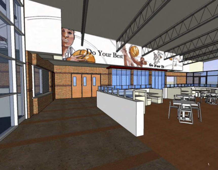
1. View of cafe in the Rec. Center2. View of Technology Cafe3. View Technology Cafe4. View of Weight room5. View of Tech. Cafe5. View into Tech. Cafe5. View of Cafe in the Rec. Center
Ray and Joan Kroc Community CenterDayton, OhioCommunity CenterJohn Poe ArchitectsWinter 2007
ThisprojectwasacommunitycenterforSalvationArmywhichconsistedoffivebuildings:aneducationalfacility,arecreationalfacility,corporateheadquarters,awomenandchildren’s shelter, andaworship facility.Aspartof theprojectteamIhelpedwithconstructiondocuments,materialselection,creatingdetails,andcreatingandmaintaininga3-Dmodelforbothclientandmarketinguse.
Theimagesaboverepresenttherecreationalfacilityandthetechnologycafe,whichisthefocalpointoftheeducationalfacility.
2. 3.
7.
4. 5. 6.


Academic Experience

1.

1. Fourth Floor Plan2. North Elevation3. West Elevation4. East Elevation5. Site Plan
Future Forms for Healthy DevelopmentCincinnati, OhioEducationThesis ProjectFall 2010 - Spring 2011
My thesis investigated the effect of nature on the emotional, physical, andmentalhealthanddevelopmentofhumans,especiallychildren.Ithenusedmyfindingstocreateadesignmethodologythatseamlesslyintegratesnatureintobuilt formwhich,when implemented,will reduce thenegativeeffects living inurbanenvironmentshasonhumanhealthanddevelopment.Thesestrategieswere then demonstrated through the design of an urban educational facilitylocatedinCincinnati,Ohio.
ThedesignwasarenovationofanexistingschoolindowntownCincinnati.Thenewdesigninvolvedretrofittingtheexistingbuildingintoamixedusespaceandadding a newwing for academic classrooms.Naturalmaterials, open plans,glazing, and vegetationwere integrated into all spaces to blur the boundarybetweentheinteriorandexteriorwhilecreatingspacesthatchangeandadaptasthechildreninteractwithandexplorethem.1.
2.
3.
4.
5.

1. Floor Plans2. Massing Model3. Biophilic Relationships Diagram4. Physical Model
SOCIOCULTURALFACTORS
ECOLOGICAL DIVERSITY
SENSE OF PLACET
INDIRECTINTERACTION
DIRECT INTERACTION
SYMBOLIC INTERACTION
T
BIOPHILICVALUES
EMOTIONAL DEVELOPMENT
INTELLECTUALSKILLS
MORAL / ETHICALPERSPECTIVES
BUILT ENVIRONMENT FACTORS
EXPERIENCE WITH NATURE
ENVIRONMENTAL VALUES
HEALTH AND DEVELOPMENT OUTCOMES
1.
2.
3.
4.

1. Building Section2. Building Layout Studies3. Classroom Program Study4. Elementary Adjacency Study5. Academic Spaces Adjacency Study
CLASSROOM PROGRAM
FIRST FLOOR CLASSROOM PROGRAM SECOND FLOOR CLASSROOM PROGRAM
Core Learning Area
Core Learning Area Core Learning Area
Core Learning Area
Focus Group
Focus Group
Core Learning Area
Outdoor Classroom
Outdoor Classroom
Eco LearningArea
Interior / ExteriorLearning Space
Social LearningArea
Activity Center
Activity Center
Small GroupLearning Area
Small GroupLearning Area
Small GroupLearning Area Small GroupLearning AreaTechnologyArea
ProjectArea Project
Area
Focus GroupFocus Group
Interior / ExteriorLearning Space
Social LearningArea
Small GroupLearning Area Small GroupLearning Area Large GroupLearningArea
Small GroupLearning Area Small GroupLearning Area
Small GroupLearning Area
Children Only Leanring Area
Interior / ExteriorLearning Space
Scale: 1/16" = 1'-0"
NORTH - SOUTH SECTION2
PRO
DU
CED
BY
AN
AU
TOD
ESK
ED
UC
ATI
ON
AL
PRO
DU
CT
PRODUCED BY AN AUTODESK EDUCATIONAL PRODUCT
PRO
DU
CED
BY A
N A
UTO
DESK
EDU
CA
TION
AL PR
OD
UC
T
PRODUCED BY AN AUTODESK EDUCATIONAL PRODUCT
CLASS CLASS
CLASS CLASS
STOR.WORK R.RKINDERGARTEN
DRIVE
EXTERIOR SPACES
PLAYGROUND
1.
2. 3.
4. 5.

1.

1. Photograph of the solar panels installed in their completed frame.2. Photograph of the final vegetated wall and solar panel systems3. Detail drawing of the two systems4. Enlarged Detail of the Vegetated Wall System5. Solar Panel Frame Detail
Learning LaboratoryCincinnati, OhioDesign/Build64 SFSpring 2010
The goal for this assignment was to design and build a learning laboratory.Theentirelaboratorywasdesignedasastudio,withspecificdetailsdesignedby four individual groups.These groupswere: interior design, exteriorwalls,vegetatedwall,andsolarpanels.Iwasoneofthreemembersinthesolarpanelandvegetatedwallgroup.Imagesofthedetaildrawingsandprocessandfinalphotographsareshownabove.
2. 3.
4.
2x3
2x4
2X6
2x3
2x4
1” BLACK IRON TUBING
2x6
4” STEEL PLATE
SOLAR PANEL2X8
4” C Channel
6” Steel Plate
2X3
2X3
2X42X4
2X6
2X62X4
2X3
PHOTOVOLTAIC PANEL
2X62X8
SECTION DETAIL B
6” = 1’-0”
SECTION DETAIL A
6” = 1’-0”
SECTION DETAIL C
6” = 1’-0”
Solar Thermal StrategiesPlans and Details
Emily KriegerEmily Samsonow
Steve Stidham
5.

2x3
2x4
2X6
2x3
2x4
1” BLACK IRON TUBING
2x6
4” STEEL PLATE
SOLAR PANEL2X8
4” C Channel
6” Steel Plate
2X3
2X3
2X42X4
2X6
2X62X4
2X3
PHOTOVOLTAIC PANEL
2X62X8
SECTION DETAIL B
6” = 1’-0”
SECTION DETAIL A
6” = 1’-0”
SECTION DETAIL C
6” = 1’-0”
Solar Thermal StrategiesPlans and Details
Emily KriegerEmily Samsonow
Steve Stidham
2x3
2x4
2X6
2x3
2x4
1” BLACK IRON TUBING
2x6
4” STEEL PLATE
SOLAR PANEL2X8
4” C Channel
6” Steel Plate
2X3
2X3
2X42X4
2X6
2X62X4
2X3
PHOTOVOLTAIC PANEL
2X62X8
SECTION DETAIL B
6” = 1’-0”
SECTION DETAIL A
6” = 1’-0”
SECTION DETAIL C
6” = 1’-0”
Solar Thermal StrategiesPlans and Details
Emily KriegerEmily Samsonow
Steve Stidham
1. Photograph of completed vegetated wall system2. Photograph of the south side of the learning laboratory3. Photograph of corner detail from above4. Photograph of corner detail from below5. Detail drawing of the solar panel frame
4.3.
2.
1.
5.

1. Teammates assembling supports2. Installing the solar panels3. Main support before installation4. Partial frame before installation
1.
2.
3.
4.

1.
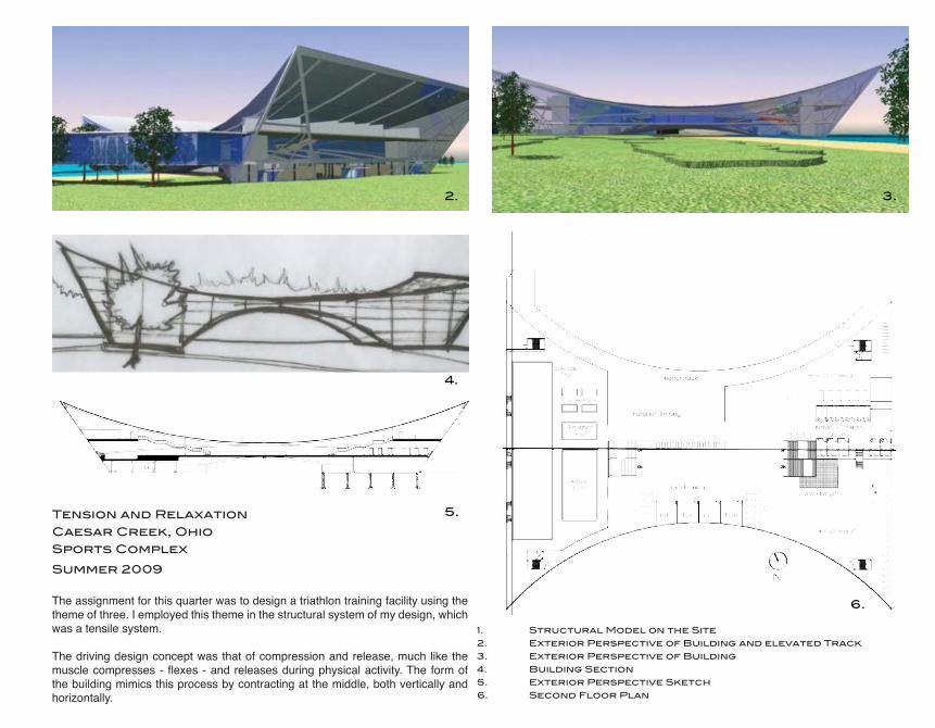
1. Structural Model on the Site2. Exterior Perspective of Building and elevated Track3. Exterior Perspective of Building4. Building Section5. Exterior Perspective Sketch6. Second Floor Plan
Tension and RelaxationCaesar Creek, OhioSports ComplexSummer 2009
Theassignmentforthisquarterwastodesignatriathlontrainingfacilityusingthethemeofthree.Iemployedthisthemeinthestructuralsystemofmydesign,whichwasatensilesystem.
Thedrivingdesignconceptwasthatofcompressionandrelease,muchlikethemusclecompresses-flexes-andreleasesduringphysicalactivity.Theformofthebuildingmimicsthisprocessbycontractingatthemiddle,bothverticallyandhorizontally.
4.
2.
7.
9.
3.
5.
6.

1.

1. Final Bay Model2. Section Perspective of Spa Spaces3. Structural Model
Cranbrook Academy Spa
Cranbrook, Michigan
Wellness Center
10,000 sf
Fall 2008 / spring 2009
This assignment was a two quarter long wellness center focusing on structure,environment,andconstruction.Thedrivingconceptofmydesignwastobothacceptandrejectanexistinggridthroughtheuseoftwocontradictorywings.Thetraditional,rectangular wing respects the grid and the existing building typology, while themodern,angularwingrejectsthegridandtypologies.
Detail andmateriality were employed to create two visually different wings, as iftheyweretwoseparatebuildings.Therectangularwing,housingthehospitalityandadministrationspaces, isdetailed tobe“heavy”usingbrickandotherstones.Theangularwing,housingallspaspaces,isdesignedtobelightusingglassandwoodmaterials.
2.
3.

1. Rendered Site Plan2. First Floor Plan3. Design Sketches4. Elevation Sketches5. Elevation Sketch6. Site / Landscape Studies
1.2.3.4.5.
PROGRAM DIAGRAMELEVATION STUDIESELEVATION STUDYCONCEPT SKETCHESSITE SKETCHES
11
STUDIO WORKSPIRITUALITY’S RELEASE
URBAN HOUSINGKADIKOY FERRY STATION
SARDINIA SPRAWLCOMMUNITY BOOKS
CRANBROOK SPA
SUPPLEMENTAL SKILLSHAND RENDERING
ABSTRACT PAINTINGFIELD SKETCHINGPHOTOGRAPHY
A MOMENT IN DAAP
PROFESSIONAL WORKDAYTON BLOOD CENTER
KROCK CENTERHEALDSBURG
FASHION ISLAND ATRIUMAMERICAN EAGLE
SystemsAll of the systems and technology of the building, such as the plumbing and HVAC, are integrated into the building in a way that makes them invisible to those inhabiting the space. The HVAC, plumbing, and equipment are integrat-ed into the foudation of the buidling. At no point is there are volumetric indi-cator of any of the systems. Having them invisible allows the spaces to have a character that is uninterupted by the technology required to functionally run the space, making it experientially seem as though the technology does not exist. This therefore allows those inhabiting the space to focus on the functions of the spaces rather than the technology running them.
ConstructionThe construction details and decisions share the same intent as the volu-metric, site, and detail ones of the building. Each space has a different construction type which emphasizes the volumetric intent of the spaces be-ing visably different from each other to emphasize the difference in function. Each space is asked to be visible constructed differently than the other space.
Systems + Construction
ARCHITECTURAL INTENT
Hospitality Spaces
Systems Spaces
Spa Spaces
CRANBROOK ART ACADEMY: GRID + AXISCampus grid + axis
1. 2.
3.
4. 5.
2.
3.
4.
5.
1.2.3.4.5.
PROGRAM DIAGRAMELEVATION STUDIESELEVATION STUDYCONCEPT SKETCHESSITE SKETCHES
11
STUDIO WORKSPIRITUALITY’S RELEASE
URBAN HOUSINGKADIKOY FERRY STATION
SARDINIA SPRAWLCOMMUNITY BOOKS
CRANBROOK SPA
SUPPLEMENTAL SKILLSHAND RENDERING
ABSTRACT PAINTINGFIELD SKETCHINGPHOTOGRAPHY
A MOMENT IN DAAP
PROFESSIONAL WORKDAYTON BLOOD CENTER
KROCK CENTERHEALDSBURG
FASHION ISLAND ATRIUMAMERICAN EAGLE
SystemsAll of the systems and technology of the building, such as the plumbing and HVAC, are integrated into the building in a way that makes them invisible to those inhabiting the space. The HVAC, plumbing, and equipment are integrat-ed into the foudation of the buidling. At no point is there are volumetric indi-cator of any of the systems. Having them invisible allows the spaces to have a character that is uninterupted by the technology required to functionally run the space, making it experientially seem as though the technology does not exist. This therefore allows those inhabiting the space to focus on the functions of the spaces rather than the technology running them.
ConstructionThe construction details and decisions share the same intent as the volu-metric, site, and detail ones of the building. Each space has a different construction type which emphasizes the volumetric intent of the spaces be-ing visably different from each other to emphasize the difference in function. Each space is asked to be visible constructed differently than the other space.
Systems + Construction
ARCHITECTURAL INTENT
Hospitality Spaces
Systems Spaces
Spa Spaces
CRANBROOK ART ACADEMY: GRID + AXISCampus grid + axis
1. 2.
3.
4. 5.
6.a. a. a. a.a.b. b. b. b. b.
c. d.e. f. f.
g. h.
i.
i. j.
k.k.k.
l.m.
m.
m.
m.
m.
n.a. GuestRoomb. GuestRestroomc. Library/Readingd. Kitchen/Dininge. Lobby/Receptionf. Restroomg. Mechanicalh. AdministrationOffices
i. Lockers/Dressingj. Saunak. Massagel. PlungePoolm Pooln. OutdoorPool
2.
1.

1.2.3.4.
BUILDING SECTIONSTRUCTURAL DIAGRAMSSTRUCTURAL MODELDIAGRAM OF THERMAL MASS
STUDIO WORKSPIRITUALITY’S RELEASE
URBAN HOUSINGKADIKOY FERRY STATION
SARDINIA SPRAWLCOMMUNITY BOOKS
CRANBROOK SPA
SUPPLEMENTAL SKILLSHAND RENDERING
ABSTRACT PAINTINGFIELD SKETCHINGPHOTOGRAPHY
A MOMENT IN DAAP
PROFESSIONAL WORKDAYTON BLOOD CENTER
KROCK CENTERHEALDSBURG
FASHION ISLAND ATRIUMAMERICAN EAGLE
12
BUILDING SECTION 2SCALE: 1/2” = 1’-0”
The interior wall that divides the hospitality spaces from the corridor acts as a thermal mass. Direct gain enters the building through the southern wall glazing system and is stored in the wall. At night when the temperature cools the wall expells the heat into the room mini-mizing the temperature flux within the space.
Both walls are bearing walls that also act as part of the structural system. The exterior wall has two brick layers and one CMU block layer. The top 6’-0” of this wall is all glazing to allow the maximum amount of direct gain into the space in the winter. The interior wall is a CMU block wall with stone tile finishing on either side.
There is an overheated portion of the year. During these times of the year the glazing system is shaded so not direct gain enters the building.
Having the glazing located here for passive heating also allows for a good opportunity to bring natural light into the space, even in the over heated parts of the year. The roof overhang that acts as the shading system shades the space completely in the summer so no interoer lou-vers or blinds are necessary.
Thermal Mass
ENVIRONMENT
Thermal Mass
Glazing; direct gain entrance
Heat dispursed into the interior at night
Direct gain in the winter
Direct gain in the summer; blocked by roof overhang
The volumetric intent for the building calls for the buiding to have two distinct structural systems; one bearing wall, one steel framing. For the hospitality spaces the bearing wall structure is integrated into the interior making. It is detailed in a way that makes it invisible. The structural system of this portion of the wellness center mimic the sur-rounding buildings on campus and the structural expressed is therefore expressed to mimic the buildings.
The structure of the spa spaces is expressed. This is to illustrate the lightness of the space and to visibly separate the structure from the skin. This further illustrates the transparency of these spaces.
The section and daigrams above are a transverse section through the hospitality spaces. This space is a single height space supported by bearing walls. The section shows the distribution of the gravity loads that exist within the build-ing. Each bearing wall is just over 1’ thick and the longest span is 20’ with the smaller span being 8’. The roof at the south wall is supported by a beam and column that were included to accomodate the recessed glazing.
Conjecture
STRUCTURE
Shear Diagram
Moment Diagram
2.
1.
3. 4.
1. Structural Diagrams2. Diagram of Existing Campus Grid3. Building Section with Environmental Studies 3.
1.
ShearDiagram
MomentDiagram
CRANBROOK ART ACADEMY: GRID + AXIS

STUDIO WORKSPIRITUALITY’S RELEASE
URBAN HOUSINGKADIKOY FERRY STATION
SARDINIA SPRAWLCOMMUNITY BOOKS
CRANBROOK SPA
SUPPLEMENTAL SKILLSHAND RENDERING
ABSTRACT PAINTINGFIELD SKETCHINGPHOTOGRAPHY
A MOMENT IN DAAP
PROFESSIONAL WORKDAYTON BLOOD CENTER
KROCK CENTERHEALDSBURG
FASHION ISLAND ATRIUMAMERICAN EAGLE
07
SARDINIA SPRAWL
SARDINIA, ITALY
URBAN PLANNING
MINIMIZING URBAN SPRAWL
SUMMER 2008
While studying abroad in Italy, I partici-pated in a 10 day summer program on the Island of Sardinia focusing on ur-ban planning. Our project was to take a low-density site and give it a sustain-able city center and minimize urban sprawl. We found that the problems on our site were a poor urban nucle-us, lack of urban services, constantly changing population, low density, and mobility, while the opportunities were environmental sources, sea, pine and juniper trees, low density, agricultural areas, wind, good climate, good infra-structure, and minimal urban traffic.
The driving concept of the master plan was to create a better quality of life for the site while keeping it low density. The driving idea of our design is the “green corridor” concept. These corridors are environmental corridors that act as public spaces with multifunctional ac-tivities. These corridors follow the in-frastructure that moves people from one city to the next. Along with creat-ing public spaces the green corridors act as boundaries. Within these corri-dors “fingers” exist that hold the public spaces and multifunctional activities.
Caroline Bohlen
Carlo Chelo
Emily Krieger
Becca Kundysek
Manuela Porceddu
Jeffrey Rengering
Rosario Romano
Roberto Sussarello
Rodrigo Velazquez Bernabeu
Professor:
G. Maciocco
The image on the top left is a diagram of the existing conditions of the site that as a group we felt were important. The diagram on the bottom left is a conceptual master plan of our project. This is where we first started to incorpo-rate the different layer opportunities together.
A n a l y s i s :Our group started by identifying the problems and opportunities that existed within our site. We found that the problems were a poor urban nucleus, lack of urban services, social problems and disease, poverty of tourist services, constant-ly changing population, low density, poverty of house morphology, and mobility. The opportunities that we found to be evident were environmental sources, sea, pine and juniper trees, low density, agricultural areas, wind, good climate, good in-frastructure, and minimal urban traffic. Our group then decided to split up the existing conditions of the site into “layers” and analyzing the layers in-dividually. The five layers that we analyzed were water, vegetation, history and urban settlements, infrastructure, and topography. In our analysis we found that the vegetation that existed on the site was mostly pine, juniper, and agricultural land. Through our research we found that neither the pine or the juniper were natural to the site. In-stead they had been brought in to protect the dunes from erosion. to be respected or preserved.
After determined the opportunities that existed with-in the site we created a master plan that incorpo-rated all of the opportunities. The driving concept of the master plan was to create a better quality of life for the site while keeping it low density. The driving idea of our design is the “green corridor” concept. These corridors are environmental corri-dors that act as public spaces with multifunctional activities. The property lines, existing housing, and sprawl within the site determined the boundaries of the corridors. These corridors follow the infra-structure that moves people from one city to the next. Along with creating public spaces the green corridors act as boundaries. Within these cor-ridors “fingers” exist that hold the public spaces and multifunctional activities. This way residents no longer need to travel into the city for every day needs. No housing is allowed in the “fingers” which therefore also act as boundaries to the sprawl.
After we determined the opportunities that exist-ed within the site we created a master plan that incorporated all of the opportunities. The driv-ing concept of the master plan was to create a better quality of life for the site while keeping it low density. The driving idea of our design is the “green corridor” concept. These corridors are environmental corridors that act as public spaces with multifunctional activities. The prop-erty lines, existing housing, and sprawl within the site determined the boundaries of the corridors.
distribuzione insediativa: infrastrutture per chi?urban distribution: infrastructures for who?
The image above is a diagram of the infra-structure within the site. The diagram shows the major cities, direction of traffic along with the different types of traffic allowed to pass.
These corridors follow the infrastructure that moves people from one city to the next. Along with creating public spaces the green corridors act as boundaries. Within these corridors “fingers” exist that hold the public spaces and multifunctional activities. This way residents no longer need to travel into the city for ev-ery day needs. No housing is allowed in the “fingers” which therefore also act as boundaries to the sprawl.
We used the infrastructure to create sustainable transportation. Where different roads meet the type of transportation allowed through changes. The roads closest to the water are strictly pedestrian and bicycle traffic. As one moves outward scoot-ers, electric car, and full size vehicles are eventually added. Along the entire road multi level pathways exist for pedestrians and bicycles to travel on. These boardwalks continued out into the water connecting the coast with the sprawl. The “fingers” in this area transform into centers for tourists to use with the final “finger” being the boardwalk that continues into the water. Each “finger” holds multifunctional spaces and buildings. The boardwalk acts as a seamless connection between the water, the dunes, the pond, the vegetation, and the urban settlements.
1.
2. 3.
GRAPHIC ANALYSIS OF PROBLEM AREASCONCEPTUAL SITE PLANGRAPHICAL ANALYSIS OF SPRAWL LOCATIONS
1.
2.3.
1.
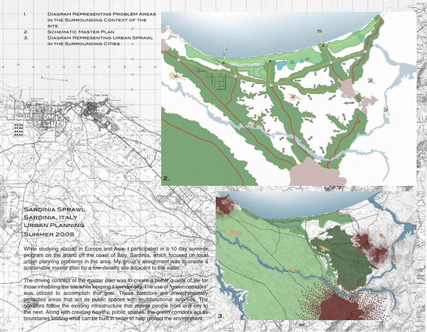
1. Caption2. Caption3. Caption4. Caption5. Caption
Sardinia SprawlSardinia, ItalyUrban PlanningSummer 2008
WhilestudyingabroadinEuropeandAsia,Iparticipatedina10daysummerprogramon the islandoff thecoastof Italy,Sardinia,which focusedon localurbanplanningproblemsinthearea.Mygroup’sassignmentwastocreateasustainablemasterplanforalow-densitysiteadjacenttothewater.
Thedrivingconceptofthemasterplanwastocreateabetterqualityoflifeforthoseinhabitingthesitewhilekeepingitlow-density.Theuseof“greencorridors”was utilized to accomplish this goal. These corridors are environmentallyprotected areas that act as public spaceswithmultifunctional activities. Thecorridors follow theexisting infrastructure thatmovespeople fromonecity tothenext.Alongwithcreatinghealthy,publicspaces,thegreencorridorsactasboundarieslimitingwhatcanbebuiltinordertohelpprotecttheenvironment.
1. Diagram Representing Problem Areas in the Surrounding Context of the site2. Schematic Master Plan3. Diagram Representing Urban Sprawl in the Surrounding Cities
2.
3.


Supplemental Skills
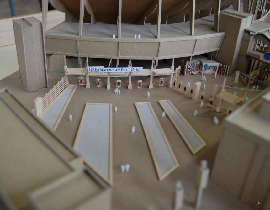
1.

Physical ModelingCincinnati Reds Stadium RenovationMichael Schuster AssociatesFall 2009 / Winter 2010
MSAproposedarenovationtotheCincinnatiRed’sStadium.Myroleaspartof theproject teamwas toupdateanexistingpresentationmodelwhich,whenfinished,wasgiventotheclientfordisplayinthecorporateoffices.Themodelwasadetailedrepresentationoffixtures,stations,andgraphicsproposedtotransformtheterracelevelofthestadiumintoamoreusable,family-friendlyspace.
1. View from Main Entrance2. View of Mini Stadium and Overlook3. View of P&G Stage4. Aerial View of Stadium5. View of Children’s Play Area6. View of P&G Stage
2.
3.
4.
5. 6.

1.

1. Yagoot floor plan rendering2. Kendle floor plan rendering
Photoshop RenderingCincinnati Design AwardsMichael Schuster AssociatesFall 2009 / Winter 2010
BothimagesonthispagearerenderedfloorplansIcompletedforsubmissiontotheCincinnatiDesignAwards.
2.
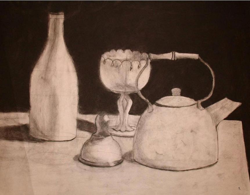
1.

1. Charcoal Still Life2. Mixed Media Drawing3. Pencil Rendering4. Graphite Still Life
Hand RenderingCharcoal, Graphite, Color PencilFall 2005
ImagesaboverepresentrenderingsdonebothforacademicandpersonalpurposeswhileattendingtheUniversityofCincinnati.
2.
3.
4.

1.1.

1. Marker sketch of the Blue Mosque in Istanbul, Turkey done using the dot method.2. Water Color of Ponte Vechio in Florence, Italy.3. Christian Church in Istanbul, Turkey.4. Site study of Kadikoy Ferry Station
Field SketchingItaly and TurkeySummer 2008 + Summer 2010
While studying abroad in Italy and Turkey in thesummer of 2008 I took a field sketching course.Throughoutthesummerwevisiteddifferentsignificantarchitectural sites and practiced different styles andmethodsofsketchingsuchaswatercolor,perspective,marker,andthedotmethod.TheimagesaboveareaselectionofthoseIdidforthiscourse.
3.
2.3.
4.


Thank You