portada manual vapor eng - steamtrapefficiency.com · the steam trap causes an abrupt change in...
TRANSCRIPT

CHAPTER I
STEAM: BASIC CONCEPTS
1.1 PHASE TRANSITIONWater steam is a thermal fluid that is widely used across the industry because ofthese notable properties:
» High energetic content
» Easy to transport
The combination of these two properties allows for the distribution of largeamounts of energy from locations that are distant from the facilities, thus takingadvantage of the steam's internal pressure to pump the fluid.
Water can exist in three different states: solid, liquid, and gas or steam. The pro-cess of moving from one state to another is called a phase transition, which is pro-duced through the exchange of energy in the form of heat. When the change ofstate occurs from a solid to a gas, the process requires energy, and when thechange occurs in the opposite direction, it releases energy.
Figure 1.1 shows the process of vaporizing water by adding heat where you cansee the three different stages.
Figure 1.1
1-1 / Steam: Basic Concepts
Steam Manual: Steam Traps, Steam Energy Traps and Smart Energy Traps
100 ºC 1 atm
Water Boiling Water Saturated SteamLatent HeatSensible Heat
PROCESS OF VAPORIZING WATER
100 Kcal/Kg 540 Kcal/Kg1 atm0 ºC 100 ºC
1 atm

Stage 1: Consists of water in the form of a liquid at atmospheric pressure and zerodegrees Celsius; as heat is added the water will rise in temperature until it reachesits boiling point, 100 degree Celsius. The amount of energy given in this processis called the sensible heat (head added to the liquid without a change in state); thisamount depends on the pressure.
Stage 2: Heat added after the boiling point results in the vaporization of water, butthe temperature remains constant while vaporization is occurring, meaning thatwater and steam are both present simultaneously. Energy absorbed in the forma-tion of steam is known as latent heat; this amount depends on pressure.
Stage 3: UOnce all of the water has become vapor, any additional heat causes thetemperature to rise and the result is superheated steam.
Figure 1-2 shows the three stages of the vaporization process.
Figure 1.2
Note that the diagram of the water-steam phases is different for each pressure, the-refore, representing this diagram for different pressure values on three-dimensionalcoordinates would provide us an area that varies on three magnitudes (pressure,temperature, and heat), where the latent heat and the saturation temperature changeaccording to the pressure.
As shown, the total energetic content of the steam is:
Total Heat = Sensible Heat + Latent Heat + Overheating
1-2 / Steam: Basic Concepts
Steam Manual: Steam Traps, Steam Energy Traps and Smart Energy Traps
Temperature
Phase diagram water-steam
Ts = Saturation TemperatureTs
Sensible Heat Latent Heat Overheating
HeatWater Water + Steam
Evaporation Zone Superheated
Steam
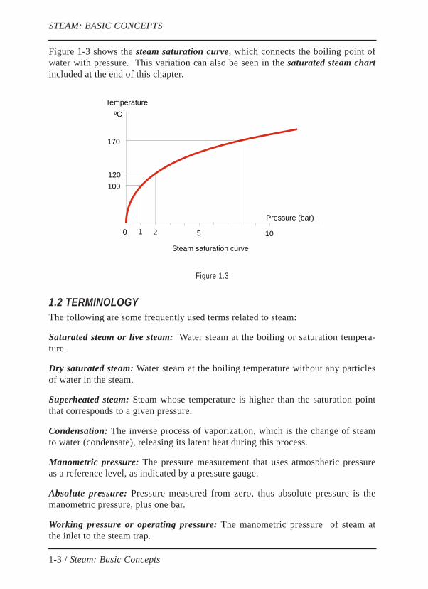
Figure 1-3 shows the steam saturation curve, which connects the boiling point ofwater with pressure. This variation can also be seen in the saturated steam chartincluded at the end of this chapter.
Figure 1.3
1.2 TERMINOLOGYThe following are some frequently used terms related to steam:
Saturated steam or live steam: Water steam at the boiling or saturation tempera-ture.
Dry saturated steam: Water steam at the boiling temperature without any particlesof water in the steam.
Superheated steam: Steam whose temperature is higher than the saturation pointthat corresponds to a given pressure.
Condensation: The inverse process of vaporization, which is the change of steamto water (condensate), releasing its latent heat during this process.
Manometric pressure: The pressure measurement that uses atmospheric pressureas a reference level, as indicated by a pressure gauge.
Absolute pressure: Pressure measured from zero, thus absolute pressure is themanometric pressure, plus one bar.
Working pressure or operating pressure: The manometric pressure of steam atthe inlet to the steam trap.
1-3 / Steam: Basic Concepts
STEAM: BASIC CONCEPTS
Pressure (bar)
170
120
0 21
100
ºCTemperature
Steam saturation curve
5 10
Backpressure: Pressure at the outlet of the steam trap, which is pressure in thewater return lines.
Differential pressure: The difference between operating pressure and backpres-sure, meaning, the pressure before the steam trap minus the pressure after.
Calorie (Cal): The amount of heat needed to raise the temperature of one gram ofwater from 14.5 degrees Celsius to 15.5 degrees Celsius.
Kilocalorie (Kcal): The amount of heat needed to raise the temperature of oneKilogram of water from 14.5 degrees Celsius to 15.5 degrees Celsius; equivalent to1000 Cal.
Specific Heat: The amount of heat that is required to raise the temperature of onemass unit of a substance one degree Celsius. It is expressed as Kcal/Kg°C.The specific heat of water = 1 Kcal/Kg°C.
Specific Volume: The volume occupied by one mass unit of a substance. It isexpressed as m3/Kg. The specific volume of steam is very large in comparisonwith that of water; for this reason, steam trap discharge is usually accompanied bya cloud of flash steam even when the steam trap is properly functioning.
Revaporization: The processing of forming vapor as a result of a drop in pressureor the expansion of condensate. The revaporized steam is also called expansionsteam or flash steam. Even though it is not generated by added heat, its energeticcontent and all the rest of its properties correspond to the saturated steam at thesame pressure. Regarding steam traps, it is essential to differentiate between livesteam and flash steam.
1.3 FLASH STEAM
Temperature and pressure of saturated steam are related in that all pressures havedifferent saturation temperatures. This connection, as well as its energetic content(enthalpy), specific volume, and other steam properties, can be checked by lookingat the saturated steam chart or the saturation curve of steam.
The saturated steam table shows sensible heat (heat of the boiling water) rising aspressure rises, while latent heat (evaporation heat or heat lost during condensation)becomes less as the pressure increases.
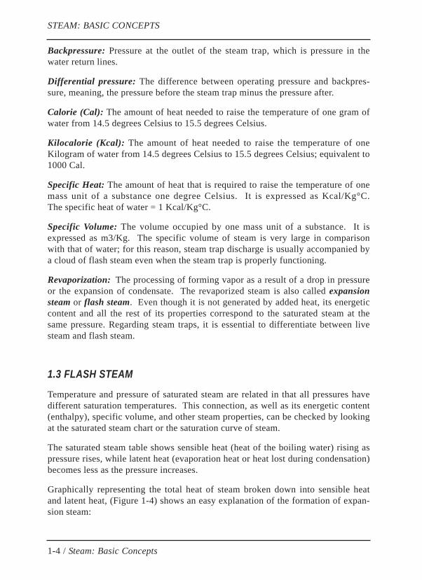
Graphically representing the total heat of steam broken down into sensible heatand latent heat, (Figure 1-4) shows an easy explanation of the formation of expan-sion steam:
1-4 / Steam: Basic Concepts
STEAM: BASIC CONCEPTS
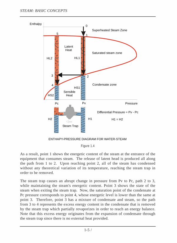
Figure 1.4
As a result, point 1 shows the energetic content of the steam at the entrance of theequipment that consumes steam. The release of latent head is produced all alongthe path from 1 to 2. Upon reaching point 2, all of the steam has condensedwithout any theoretical variation of its temperature, reaching the steam trap inorder to be removed.
The steam trap causes an abrupt change in pressure from Pv to Pc, path 2 to 3,while maintaining the steam's energetic content. Point 3 shows the state of thesteam when exiting the steam trap. Now, the saturation point of the condensate atPc pressure corresponds to point 4, whose energetic level is lower than the same atpoint 3. Therefore, point 3 has a mixture of condensate and steam, so the pathfrom 3 to 4 represents the excess energy content in the condensate that is removedby the steam trap which partially revaporizes in order to reach an energy balance.Note that this excess energy originates from the expansion of condensate throughthe steam trap since there is no external heat provided.
1-5 /
STEAM: BASIC CONCEPTS
Differential Pressure = Pv - Pc
Pc Pv
Steam Trap
Sensible Heat
Latent Heat
Enthalpy
Pressure
H1H2
HL2 HL1
HS2
HS1
H1 = H2
ENTHAPY-PRESSURE DIAGRAM FOR WATER-STEAM
1
23
4
5Superheated Steam Zone
Saturated steam zone
Condensate zone
0
In summary, there is always a discharge of condensate and expansion steam whena steam trap is working at the saturation temperature, in a way in that the energeticcontent of the liquid phase (condensate) is precisely the sensible heat of the con-densate at the pressure of the collector, while the rest of energy from point 4 to 3in the diagram's evaporation zone corresponds to the presence of a certain amountof expansion steam that is formed during this process.
The quantity of revaporized content that is formed by a unit of mass of the conden-sate that is removed, is the quotient between the enthalpy of path 3-4 and theenthalpy of path 5-4, which is the quotient of the steam's different enthalpiesbefore and after the purgadorsteam trap (h2-h4) divided by the latent heat of eva-poration at the outlet pressure of the steam trap (h5-h4):
Revaporization per unit of mass = (h2-h4) / (h5-h4)
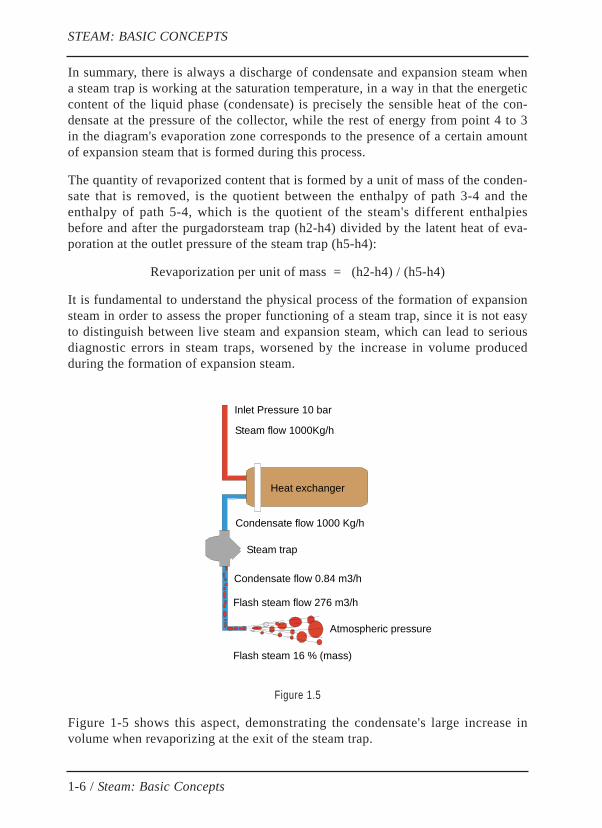
It is fundamental to understand the physical process of the formation of expansionsteam in order to assess the proper functioning of a steam trap, since it is not easyto distinguish between live steam and expansion steam, which can lead to seriousdiagnostic errors in steam traps, worsened by the increase in volume producedduring the formation of expansion steam.
Figure 1.5
Figure 1-5 shows this aspect, demonstrating the condensate's large increase involume when revaporizing at the exit of the steam trap.
1-6 / Steam: Basic Concepts
STEAM: BASIC CONCEPTS
Steam trap
Inlet Pressure 10 bar
Heat exchanger
Condensate flow 1000 Kg/h
Atmospheric pressure
Condensate flow 0.84 m3/h
Steam flow 1000Kg/h
Flash steam flow 276 m3/h
Flash steam 16 % (mass)

Note that even though the mass of condensate is much higher than that of flashsteam, the opposite observation can be made when comparing their volumes (276m3/h of flash steam over 0.840 m3/h of condensate).
1.4 THE DIFFERENCE BETWEEN LIVE STEAM AND FLASH STEAMThe only difference between live steam and expansion steam lies in the processthat created it, but once they become steam, both have the same chemical andphysical properties. This makes visual detection of live steam leaks difficult whenobserving discharge from the steam traps. Diagnosis get more complicated in ins-tallation with hundreds or thousands of steam traps, where the discharge fromsome may locally alter the backpressure in the shared condensate collector; thismakes it very difficult to distinguish live steam from expansion steam.
Ambient temperature and relative humidity of the air greatly affect the aspect ofsteam traps discharge; expansion steam is much more visible on cold and humiddays than on warm and sunny days.
With experience, it is sometimes possible to differentiate live steam and expansionsteam discharge with the naked eye,when there is a small amount of live steam.When observing steam trap discharge, the revaporized steam is always accompa-nied by some condensate, make for a more humid aspect than live steam. Revapo-rized steam is a little opaque and humid, while live steam is transparent and itdischarges at a higher velocity and with more noise right at the exit of the steamtrap (see figure 1-6). A precise assessment can only be made with the help ofreliable detection equipment.
Figure 1.6
It is always important to reduce the amount of revaporized steam in draining sta-tions, especially in large facilities where very large facilities or future expansionsmay cause high local backpressure which keeps the system from functioning pro-perly and affects its energetic output.
1-7 / Steam: Basic Concepts
STEAM: BASIC CONCEPTS
Water + Flash Steam Life Steam
DISCHARGE OF A STEAM TRAP INTO THE ATMOSPHERE
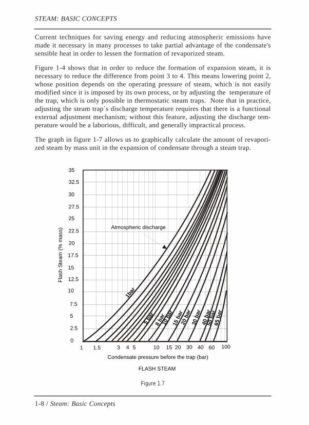
Current techniques for saving energy and reducing atmospheric emissions havemade it necessary in many processes to take partial advantage of the condensate'ssensible heat in order to lessen the formation of revaporized steam.
Figure 1-4 shows that in order to reduce the formation of expansion steam, it isnecessary to reduce the difference from point 3 to 4. This means lowering point 2,whose position depends on the operating pressure of steam, which is not easilymodified since it is imposed by its own process, or by adjusting the temperature ofthe trap, which is only possible in thermostatic steam traps. Note that in practice,adjusting the steam trap´s discharge temperature requires that there is a functionalexternal adjustment mechanism; without this feature, adjusting the discharge tem-perature would be a laborious, difficult, and generally impractical process.
The graph in figure 1-7 allows us to graphically calculate the amount of revapori-zed steam by mass unit in the expansion of condensate through a steam trap.
Figure 1.7
1-8 / Steam: Basic Concepts
STEAM: BASIC CONCEPTS
1bar
5 bar
8 ba
r
15 b
ar
10 b
ar
20 b
ar30
bar
40 b
ar50
bar
65 b
ar
1 1.5 3 4 5 10 15 20 30 40 60 100
Condensate pressure before the trap (bar)
0
2.5
5
7.5
10
12.5
15
17.5
20
22.5
25
27.5
30
32.5
35
Flas
h St
eam
(% m
ass) Atmospheric discharge
FLASH STEAM

Ambient temperature and relative humidity of the atmosphere greatly affect theaspect of steam traps discharge. In very cold and humid winter days, expansionsteam in steam trap discharge is easily visible, giving the impression that there is alarge steam leak; on the other hand, hot and dry summer days greatly lessen theappearance of expansion steam.
1.5 PROBLEMS CAUSED BY EXPANSION STEAMThe partial revaporization of the condensate in the discharge of the steam trap isone of the sources for diverse types of serious problems, namely:
Operational Problems:
» Line cooling and a reduction in the efficiency of heating processes
» Appearance of thermal water hammering
» Difficulty in regulating processes of heat exchange
» Solidification of viscous products in process equipment and lines
Energetic and Environmental Problems:
» Increase in steam leaks
» Increase in CO2 emissions into the atmosphere
» Difficulty in recovering condensate and residual energy
» Increase in noise and humidity in the processing units
Inspection and Mainaintance Problems:
» Difficulty in inspecting steam traps
» Increase in erosion of the condensate return network
» Increase in internal wear and tear of the steam traps
» Breakage of elements and gaskets produced by water hammering
» Increase in corrosion due to a more humid environment
All of these problems are generally caused by the elevation of backpressure in thewater return collector, originated as a product of the enormous increase in specificvolume experienced by the condensate upon becoming partially revaporized in thesteam trap discharge (see figure 1-5).
1-9 / Steam: Basic Concepts
STEAM: BASIC CONCEPTS
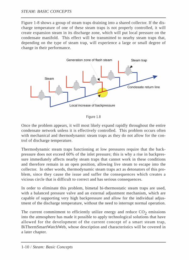
Figure 1-8 shows a group of steam traps draining into a shared collector. If the dis-charge temperature of one of these steam traps is not properly controlled, it willcreate expansion steam in its discharge zone, which will put local pressure on thecondensate manifold. This effect will be transmitted to nearby steam traps that,depending on the type of steam trap, will experience a large or small degree ofchange in their performance.
Figure 1.8
Once the problem appears, it will most likely expand rapidly throughout the entirecondensate network unless it is effectively controlled. This problem occurs oftenwith mechanical and thermodynamic steam traps as they do not allow for the con-trol of discharge temperature.
Thermodynamic steam traps functioning at low pressures require that the back-pressure does not exceed 60% of the inlet pressure; this is why a rise in backpres-sure immediately affects nearby steam traps that cannot work in these conditionsand therefore remain in an open position, allowing live steam to escape into thecollector. In other words, thermodynamic steam traps act as detonators of this pro-blem, since they cause the issue and suffer the consequences which creates avicious circle that is difficult to correct and has serious consequences.
In order to eliminate this problem, bimetal bi-thermostatic steam traps are used,with a balanced pressure valve and an external adjustment mechanism, which arecapable of supporting very high backpressure and allow for the individual adjus-tment of the discharge temperature, without the need to interrupt normal operation.
The current commitment to efficiently utilize energy and reduce CO2 emissionsinto the atmosphere has made it possible to apply technological solutions that haveallowed for the development of the current concept of a smart steam trap,BiThermSmartWatchWeb, whose description and characteristics will be covered ina later chapter.
1-10 / Steam: Basic Concepts
STEAM: BASIC CONCEPTS
Steam trapGeneration zone of flash steam
Local increase of backpressure
Steam

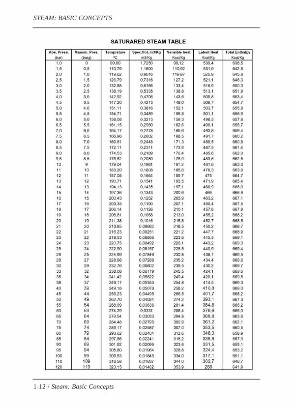
1.5 SATURATED STEAM TABLE
The following page shows the saturated steam table with useful information forcalculations, such as specific volume, sensible enthalpy, total enthalpy, and latentheat of vaporization. Note that the last column of the table, latent heat of vapori-zation, is the difference between the steam's total enthalpy and water's totalenthalpy at the boiling temperature of that pressure, as shown in figure 1-4.
It is interesting to point out that while the enthalpy of boiling water continuouslygrows as the pressure rises (see column 4 of the table), the same does not occurwith the total enthalpy of steam (column 5) which reaches it maximum value at apressure of 30 bars, then decreases when it passes the aforementioned pressure.
Latent heat of vaporization, which is primarily used in heat exchange processes,continuously decreases as the pressure increases, which is why steam consumptionwill be reduced if the operating pressure is kept low.
However, there is a minimum pressure as there is a need for the condensate toreach a certain heating temperature in the process, which depends on steam pres-sure (columns 1 and 2).
1-11 / Steam: Basic Concepts
STEAM: BASIC CONCEPTS
1-12 / Steam: Basic Concepts
STEAM: BASIC CONCEPTS

CHAPTER 2
CONDENSATE AND STEAM NETWORKS
2.1 BASIC CONCEPTSIn simple terms, a steam network is a semi-closed circuit that consists of four basiccomponents (figure 2.1):
» Steam Generators
» Steam Distribution Network
» Steam-Using Equipment
» Condensate Return Line
Figura 2.1
2-1 / Condensate and Steam Networks
Steam Manual: Steam Traps, Steam Energy Traps and Smart Energy Traps
Línea de distribución
Consumidores de vapor
Purgadores
Colector de retorno
Tanque decondensado
ESQUEMA SIMPLIFICADO DE INSTALACIÓN DE VAPOR
Bomba

In a steam system, there are two distinctly different energetic levels that are alwayspresent; their boundary is established by the control elements known as steamtraps and steam energy traps.
The saturated steam table shows that the energy per unit of mass (total heat of thesteam) in the high energy zone is four or five time higher than that correspondingto the low energy zone (sensible heat of the condensate). In steam-using equip-ment, latent heat is released, producing the phase transition (steam condensation).
The transformation of energy in the system is produced in a continuous cyclewhich is why the overall energy efficiency is much higher the less energy that isrecycled through it, taking maximum advantage of the steam's energy before sen-ding it to the condensate zone.
From a functional point of view, it is also necessary to minimize the injection ofsteam energy in the condensate zone in order to prevent serious problems fromappearing in the system (water hammer, high backpressure, cavitation in the boilersupply pumps, etc.).
In addition, raising the energy efficiency of the steam system reduces the amountof fuel needed to generate steam, which reduces CO2 emissions and therefore theamount of air pollution.
As a result, it is essential to establish a physical barrier between the two energeticlevels in the steam system, keeping energy from passing from the high-energyzone to the low energy zone.
Now, steam condenses when releasing energy and the condensate that is formed inthe area from the heat exchange must be removed in order to keep the heatexchange area exposed to steam, thus, maintaining a high heat exchange rate sincethe rate of the condensate's heat exchange is 100 times less than that of steam.
All of this leads to the need to remove the condensate that is produced in the steamzone, or the high energy level zone, simultaneously preventing steam from movingto the condensate zone, or the low energy level zone. This essential mission iscarried out by means of a wide variety of old mechanical devices known as steamtraps and more efficient elements as steam energy traps.
Note that even though these terms are often confused, this manual distinguishesbetween steam traps and steam energy traps, since their application not onlyaffects the performance and functionality of the system but it also affects otherrelevant aspects, including the system's energy efficiency, the emission of green-house gases, and the maintenance of the steam system. Finally, the perfection ofthe concept of the steam energy traps has lead to the development of modern inte-lligent energy traps.
2-2 / Condensate and Steam Networks
Steam Manual: Steam Traps, Steam Energy Traps and Smart Energy Traps
2.2 DIFFERENCES BETWEEN STEAM TRAPS AND STEAM ENERGYTRAPSWhen referring to draining elements in steam systems, it is normal to use steamtraps. However, when referring to energy efficiency in steam networks it is moreappropriate to use steam energy traps.
There is a great difference between these two concepts.
The steam trap, or simply trap, is adrain component that is activated by changesin the state of the fluid (water or steam), but it lacks the capacity to control theresidual energy of the condensate.
The steam energy trap is an automatic valve that is driven by the energetic level ofthe fluid, and therefore has the ability to control the steam energy and residualenergy of the condensate.
The essential difference between a trap and an energy trap is precisely this energe-tic control characteristic that is only found with the energy trap. This is why theenergy efficiency of the energy controller is higher than that of the trap.
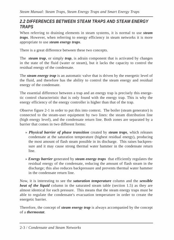
Observe figure 2-1 in order to put this into context. The boiler (steam generator) isconnected to the steam-user equipment by two lines: the steam distribution line(high energy level), and the condensate return line. Both zones are separated by abarrier that comes in two different forms:
» Physical barrier of phase transition created by steam traps, which releasescondensate at the saturation temperature (highest residual energy), producingthe most amount of flash steam possible in its discharge. This raises backpres-sure and it may cause strong thermal water hammer in the condensate returnline.
» Energy barrier generated by steam energy traps that efficiently regulates theresidual energy of the condensate, reducing the amount of flash steam in thedischarge; this also reduces backpressure and prevents thermal water hammerin the condensate return line.
Now, it is interesting to see the saturation temperature column and the sensibleheat of the liquid column in the saturated steam table (section 1.5) as they arealmost identical for each pressure. This means that the steam energy traps must beable to regulate the condensate's evacuation temperature in order to create theenergetic barrier.
Therefore, the concept of steam energy trap is always accompanied by the conceptof a thermostat.
2-3 / Condensate and Steam Networks
Steam Manual: Steam Traps, Steam Energy Traps and Smart Energy Traps

In order to assess the differences that exist between the concepts of a trap and anenergy trap, we must analyze the processes that occur in each of them (Figure 2.2).
Figura 2.2
» Discharge process in steam traps: Once the live steam has released its latentheat (HL1), it condenses and reaches point 2 (physical barrier of the changefrom steam to water). At this point, the trap opens and sends all of the residualenergy of the condensate to the return line, (point 3). At the Pc pressure in thereturn line, a part of this residual energy (section 3 to 4) revaporizes a certainamount of the evacuated condensate, producing destructive consequences.
» Discharge process in steam energy traps: The temperature control in theopening of the steam energy trap allows us to adjust point 2 to position 2A,which is more favorable for each process as it takes advantage of the residualenergy of the condensate, increasing energy efficiency and preventing thepreviously mentioned unfavorable consequences.
2-4 / Condensate and Steam Networks
Steam Manual: Steam Traps, Steam Energy Traps and Smart Energy Traps
Pres. Dif. = Pv - Pc
Pc Pv
Purgador
CalorSensible
CalorLatente
Entalpía
Presión
H1H2
HL2 HL1
HS2
HS1
H1 = H2
REGULACIÓN TERMOSTÁTICA DEL PUNTO DE DESCARGA
1
23
4
5
Zona deVapor saturado
Zona deCondensado2A

Note that when there is an excess of residual energy discharged into the return line,this excess energy is usually spread out along the same line or it is removedthrough an atmospheric vent in the condensate tank. On the other hand, circulatingflash steam and condensate at high speeds produces erosion and damages piping,elbows, and valves.
A simple calculation in a low pressure system demonstrates that using residualenergy (section 3 to 4) accounts for 8 % of the steam energy (section 1 to 2), mea-ning that there is an 8 % savings in the consumption of steam, which also saves thesame amount of treated water consumed.
As a result, using energy controllers instead of steam traps in large steam networksthat have thousands of drain points (eg. refineries, petrochemical industry, …)generates the following advantages:
» Increase in energy efficiency (8 %)
» 8 % reduction in the consumption of treated water
» Reduction in CO2 emissions (2.3% using fuel oil)
» Reduction of backpressure in the condensate return line
» Prevention of thermal water hammer
» Reduction in maintenance costs (less erosion on valves, energy controllers,accessories, …)
2.3 CONDENSATE AND STEAM NETWORK COUPLING A condensate network is coupled with the steam network when the pressure in thecondensate return line follows the steam system's variations; this phenomenon iscommon in large facilities that have thousands of working steam traps.
Section 2.1 showed the need to establish a barrier between the high and low energyzones (steam and condensate), which is created by steam traps and steam energytraps.
This aspect offers a different definition of the term steam trap and steam energytrap, as elements that are able to produce the largest load loss possible withoutaffecting the proper functioning of the steam and condensate systems.
To clarify this concept, understand that during start-up of the facility, the conden-sate is very cold and the steam energy trap barely holds any fluid back, and as thecondensate gets hotter the steam energy trap begins to shut off (increasing the loadloss) until the live steam arrives and it closes entirely (100% load loss).
2-5 / Condensate and Steam Networks
Steam Manual: Steam Traps, Steam Energy Traps and Smart Energy Traps
As for thermodynamic and inverted bucket steam traps, this process is not conti-nuous but rather intermittent. Each time the steam trap opens the load loss is smalland it unfavorably increases the pressure in the condensate return line. The incre-ase in backpressure and the trap's deterioration over time will increase the rate ofdischarges, which will also reduce the load loss generated by the trap.
Network coupling is produced by an error or inefficiency of the elements (steamtraps and steam energy traps) that are meant to create the energy barrier betweenthe system's condensate and steam zones. In this circumstance, pressure in thecondensate return line increases as it tries to balances with that of the steam. Thisreduces the differential pressure in steam traps and steam energy traps which causeserious problems in the system's operations (lack of condensate evacuation capaci-ties, strong thermal water hammer, high steam consumption, impossibility of reco-vering condensate, etc.).
Obviously, the solution to this problem is to raise the load loss in steam traps andsteam energy traps until they reach the highest amount compatible with each appli-cation. This is a conceptually simple solution; however it is practically impossiblewhen using steam traps. In the case of steam energy traps, on the other hand, this ispossible by simply changing the position of point 2 (Figure 2-2). This reduces thecondensate's discharge temperature, which reduces the formation of flash steamand backpressure in the condensate return line, lowering network coupling.
Two important conclusions are gathered from this:
» Steam Traps contribute to network coupling
» Steam Energy Traps reduce network coupling
In practice, adjusting the discharge temperature is only functional if the steamenergy trap has an external adjustment mechanism. This way, we can dynamicallyact on the energy trap as we directly and immediately verify the results in the pro-cess and its effects over the condition of the network.
Note that this external adjustment mechanism is able to function while the steamenergy trap is in operation, as the contrary would not allow for dynamic action andit would lose its purpose.
The external adjustment mechanism working in BiTherm traps (Bi-Thermostaticsteam energy traps) allows for other notable advantages such as the ability to makerepairs without needing replacement parts or having to stop the energy trap fromfunctioning.
All of this significantly reduces maintenance costs.
2-6 / Condensate and Steam Networks
Steam Manual: Steam Traps, Steam Energy Traps and Smart Energy Traps
2.4 STEAM TRAPS OR STEAM ENERGY TRAPS?Now that we see the differences of the concepts of steam traps and steam energytraps, it is worth understanding the situations in which one concept should be usedover the other.
The diversity of the processes and applications that require steam, translates intodemands that are very flexible, and sometimes contradictory, which require diffe-rent types of steam traps and steam energy traps in order to perform the best forthe needs of the specific service (in some cases, using both concepts can yieldacceptable results).
For example, for the proper functioning of a rotating cylinder dryer in a paper ortextile industry, it may be necessary to leak a small continuous amount of steamwhile non-critical tracer applications require condensate discharge temperature tobe 40 degree below the steam's saturation temperature. Between both examples,there is a large variety of applications where it is necessary to analyze the processin order to decide which is the most appropriate element to use.
To clarify, the average temperature of the condensate that reaches the steam trap orsteam energy trap in all heat exchange processes is around 10 degrees Celsius lessthan the steam's saturation temperature. This fact allows ussing thermostatic steamtraps without the risk of retaining condensate in the heat exchange equipment.However, certain applications require lower condensate evacuation temperatures inorder to compensate for oversized heat exchangers, which greatly reduces the con-sumption of steam.
However, the steam trap or the steam energy trap should not be thought of as anisolated component, but rather as a piece that it integrated in the system which isused to prevent negative effects caused by the various parts that are connected tothe system.
In effect, a steam facility can have applications that use superheated steam (turbi-nes, cylinder dryers, etc.) and others that use saturated steam (heat exchangers,tanks, tracing lines, etc.). Additionally, the steam used goes through a wide rangeof pressure and temperature. Sometimes the condensate from various applicationsis driven by the same return line. All of this produces strong interactions whichcan create serious operational problems.
Using certain steam traps (thermodynamic, labyrinth, and inverted bucket) produ-ces continuous or intermittent discharges of certain amounts of live steam with anelevated energetic level (point 1, figure 2-2) in the condensate return line (theenergetic content of the live steam is situated above point 1 in superheated steamapplications); these discharges are accompanied by high temperature condensatethat produces additional flash steam in the condensate return line.
2-7 / Condensate and Steam Networks
Steam Manual: Steam Traps, Steam Energy Traps and Smart Energy Traps
Therefore, indiscriminate use of steam traps leads to the existence of a mix of con-densate, flash steam, and live steam in the condensate return line, whose varyingenergetic levels cause serious operational and economic consequences.
On the contrary, the use of steam energy traps prevents the possibility of dischar-ging live steam and it controls the condensate's evacuation temperature, limitingthe formation of flash steam in the return line.
In conclusion, all of the characteristics of each process should be analyzed indetail, there must be energetic balance in all applications, the energetic level andthe required energy must be evaluated and compare to the supplied energy, andfinally, the optimum residual energy of the condensate must be determined.
All of this information is necessary for determining the position of point 2 (figure2-2). The operational temperature of the steam energy trap will not only determinethe performance of the entire facility, but it will also determine its energy effi-ciency and future maintenance costs.
Analyzing all of this information will provide the suitability for use of steam trapsor steam energy traps.
The condensate return line in large facilities (refineries, petrochemical plants, etc.)is very sensitive to persistent problems caused by backpressure and thermal waterhammer. In order to avoid this without increasing the diameter of the return line,steam energy traps must be used in place of steam traps so that the energy of thecondensate may be controlled.
As a general rule, steam energy traps should be used in all applications that requireprecise energy control or a continuous control of residual energy from the conden-sate, limiting the use of steam traps to applications where it is essential to guaran-tee the total absence of condensate before the steam trap.
Finally, the steam energy trap may also be utilized, in unique ocasions, as a steamtrap when it is important to make sure that there is a small controlled live steamleak, which would require the discharge temperature to be raise to the steam's satu-ration point.
2.5 THE IDEAL STEAM ENERGY TRAPFrom a practical point of view the steam energy trap has to be able to carry out thefollowing functions:
» Evacuate condensate without loss of steam
» Evacuate incondensable air and gas
2-8 / Condensate and Steam Networks
Steam Manual: Steam Traps, Steam Energy Traps and Smart Energy Traps
Now, from an operational stand point, the energy controller should posses additio-nal services, such as:
» High reliability
» High energy efficiency
» Energetic control of condensate
» Easy maintenance, preferably without interrupting service
» Strength and versatility
» Auto detection of changes in its work condition
» High quality
Obviously in practice it is difficult to fulfill all of these conditions, thus, the realsteam energy trap has to get as close as possible to the ideal in order to fulfill thosepreviously listed characteristics that are essential for the particular service provi-ded, sacrificing the less influential ones.
Over the decades, traps and energy traps have been slowly developing their mecha-nics. On 1996, the addition of micro-electronics in the bithermostatic energy traphas given birth to the patented BiTherm SmartWatchWeb or Smart Energy Trap, astrong energy regulator that completely resolves all of the problems that comefrom the size and complexity of facilities and the continuous rising of the price ofthe energy. The Smart Energy Trap (chapter 5) can reduce between 8 % and 15 %of steam consumption in facilities (chapter 9).
Historical outline:
Bitherm has pioneered the design and manufacture of smart energy traps. The firstsmart traps (see www.bitherm.com SmartWatch steamwatch and InternationalPatent No. PCT / ES97 / 00181, US 6,338,283 B1, ES9601878, ES9700044, ...)combines a bi-thermostatic trap with an electronic device with microprocessorcapable of monitor up to four independent parameters. Thus, the genuine smartenergy trap is able to evaluate the energy efficiency of the trap, identify any trou-ble either in the trap or in the electronic system. The smart energy trap incorpora-tes an external adjustment device which allows to solve any problem withoutinterruption of work, resulting in the most suitable to prevent and solve criticalproblems in the facilities (backpressure, water hammer, energy savings, simplifiedmaintenance, reduction of CO2 emissions, prevention of pollution, etc.).
2-9 / Condensate and Steam Networks
Steam Manual: Steam Traps, Steam Energy Traps and Smart Energy Traps
CHAPTER 3
STEAM TRAPS
3.1 INTRODUCTION
As mentioned in chapter 2, the steam trap is an automatic mechanical drainingelement that does not have the ability to regulate the temperature of the condensatedischarge.
Its operation does not depend on the energycontent of condensate, but rather thephysical state of the fluid (liquid or steam). This mean, in the best case, the trapopens in the presence of condensate, whatever its energy content may be, and itcloses when there is steam. In other situations, the trap closes only after havinglost a quantity of live steam (control steam).
Since the appearance of the orifice plate, the first steam trap in history, other trapdesigns have been appearing with the purpose of improving performance.
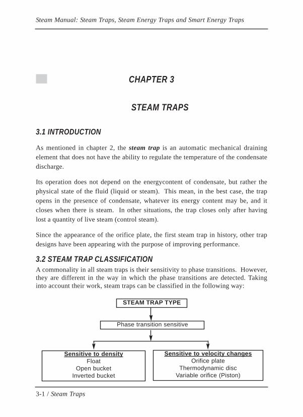
3.2 STEAM TRAP CLASSIFICATIONA commonality in all steam traps is their sensitivity to phase transitions. However,they are different in the way in which the phase transitions are detected. Takinginto account their work, steam traps can be classified in the following way:
3-1 / Steam Traps
Steam Manual: Steam Traps, Steam Energy Traps and Smart Energy Traps
STEAM TRAP TYPE
Phase transition sensitive
Sensitive to densityFloat
Open bucketInverted bucket
Sensitive to velocity changesOrifice plate
Thermodynamic discVariable orifice (Piston)

Density sensitive steam traps are based on the buoyancy of a float, open or closed,which moves a valve depending on the level of condensate on the inside of thetrap.
The group of stream traps that are sensitive to changes in the velocity of fluid isbased on the large difference between the specific volume of condensate and thatof steam. Steam passes through a hole at a much higher velocity than that of con-densate; this fact means that there are differences in pressure which are used tocontrol the trap's opening and closing.
Taking into account the design of the steam trap valves, they can be classified inthe following way:
» Differential pressure valve
» Balanced pressure valve
» Pilot valve
The valve cone of the balanced pressure valve is submerged in a uniform pressurefield where the sum of the forces on the valve cone is null. Because of this, thebalanced pressure valve can work independently of the backpressure present in thetrap's discharge. This type of valve is ussually applicable with certain float traps.
The differential pressure valve uses the difference of the inlet and outlet pressureto regulate the cone. This fact must be highly considered when sizing the steamtrap.
Pilot valve uses a small valve which acts on a larger or main valve. Pilot valvetraps are usually used to evacuate large volumes of water or under extreme diffe-rential pressure situations.
3.3 CYCLICAL AND CONTINUOUS TRAPSAccording to the way in which they function, traps can be classifieds as shown:
3-2 / Steam Traps
Steam Manual: Steam Traps, Steam Energy Traps and Smart Energy Traps
TYPE OF DISCHARGE
Orifice plateOpen bucketBuoy or Float
Variable orifice (Piston)
Thermodynamic discInverted bucket
CYCLICA CONTINUOUS
Note that the production of condensation in industrial processes occurs conti-nuously, without abrupt fluctuations, which means that there are more advantagesto continuous discharge systems than cyclical ones.
The evacuation capacity of continuous discharge traps automatically adjusts aslong as condensate is being produced. This creates a dynamic balance that preventssudden pressure oscillations in the condensate return line.
On the other hand, cyclical discharge traps must be oversized in order to compen-sate in the active part of the cycle for the capacity lost in the passive part of thecycle. Discharging intermittently provokes pressure and backpressure oscillationsthat can affect other traps and produce strong water hammering.
In a cyclical system, it is normal to lose live steam before the trap closes. When itopens, a cyclical system should quickly eliminate the condensate that has accumu-lated; this causes a drop in the pressure before the element and a slight drop intemperature. At the same time, the discharge produces a rise in backpressure,reducing the pressure difference that acts on the trap.
In summary, the obvious advantages of the continuous discharge system over thecyclical one are:
» Balance between production and condensate evacuation
» Smoother working installation
» Higher energy efficiency
» Improved control of the system's operation
» Improved control of steam leaks
» Lower network coupling
» Higher differential pressure in the system
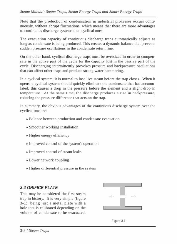
3.4 ORIFICE PLATEThis may be considered the first steamtrap in history. It is very simple (figure3-1), being just a metal plate with ahole that is calibrated depending on thevolume of condensate to be evacuated.
Figure 3.1
3-3 / Steam Traps
Steam Manual: Steam Traps, Steam Energy Traps and Smart Energy Traps

In reality, the orifice plate cannot be considered a true steam trap, since it does notinclude a valve but rather a fixed orifice that results in a load loss, which increaseswith the flow volume or the phase transition of the fluid (liquid - steam).
Live steam that passes through the orifice at a high speed produces a load loss thatpartially stops the flow, and to a certain extent, reduces the large steam losses thatare possible if the equipment is not properly measured.
The advantages of this element are:
» Maximum simplicity
» Large pressure range
» Limited maintenance
Its disadvantages are clear:
» Very critical sizing
» Limited flexibility
» Large loss of live steam
» Increase in backpressure in the condensate return line
3.4 FLOAT TRAPThis was the first automatic drain element used in the industry; it uses a valve isregulated by the water level (Figure 3-2).
Figure 3.2
3-4 / Steam Traps
Steam Manual: Steam Traps, Steam Energy Traps and Smart Energy Traps
Its mechanics is made up of a long lever (L), joined at one of the ends, and a clo-sed buoy or float on the other side, which provides the buoyancy (E). Somewherein the middle is the valve (V) with an area (S). The level of the liquid causes thevalve to open and close.
On one side, the cone valve is subject to the bouyancy force (E), transmitted by thebuoy, and on the other side, the differential service pressure. So therefore, in orderfor the valve to work, there must always be enough bouyancy force reserved toopen the valve when it experiences the highest differential pressure for closing.This can be explained as:
E x L > P x S
That is why it is always important to consider the area of the discharge orifice andthe maximum working differential pressure. In order to evacuate large amounts ofwater, we would need an orifice with a large diameter with requires an increase inthe size of the float or the arm of the lever, thus, the size of the trap itself.
For evacuating incondensable gases it is common to use a thermostatic air vent inthe form of a capsule, bellows or bimetallic, or even a small manual air extractorvalve. The thermostat has to be bimetallic if it works with superheated steam.Some substitute the automatic vent for a small internal by-pass hole that, inconve-niently, releases live steam continuously.
It is necessary to consider the following aspects when sizing a float trap:
» Maximum differential pressure. This should not exceed the amount as indica-ted by the manufacturer.
» Minimum differential pressure. It should evacuate the maximum workingload upon start-up and in a continuous cycle.
» Maximum working pressure. The maximum amount as indicated by themanufacturer
» Type of air vent required.
These traps usually come equipped with an external lever that lifts the float andopens the internal valve when necessary; however, it is important to note that thislever is in no way an external adjustment mechanism of the water flow, but ratheran element that voids the float, making it an open by-pass.
A specific type of these traps is known as a free float. In this model, the float is notrigidly connected to any element; but instead, it freely floats on the inside of thetrap. The valve seat is located in the lower part of the body and it is closed whenthe float descends to its lowest point, closing the discharge orifice.
3-5 / Steam Traps
Steam Manual: Steam Traps, Steam Energy Traps and Smart Energy Traps
The range of differential pressure of the free float trap is less than the conventionalfloat trap because the force of the float is not amplified by the lever's effect.
The advantages characteristic of floats traps are:
» They withstand variations in condensate load and differential pressure
» Continuous evacuation at the condensate's saturation temperature
» Easily discharge dirty and oily condensate
Its main disadvantages are:
» Traps are robust, heavy, and costly. High indirect steam loss
» Mounting position is fixed
» Lacks a filter and a check valve
» Sensitive to freezing and water hammers
» Does not allow for variations in its discharge temperature
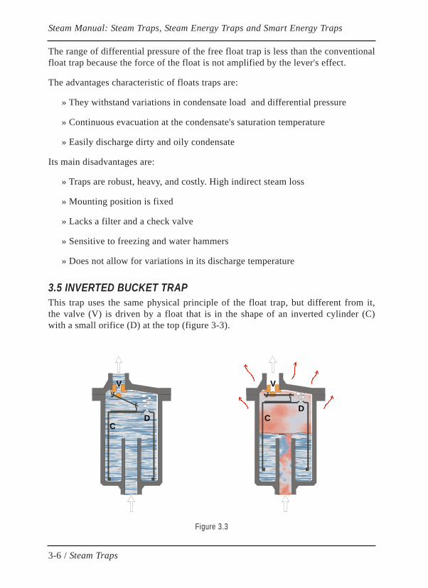
3.5 INVERTED BUCKET TRAPThis trap uses the same physical principle of the float trap, but different from it,the valve (V) is driven by a float that is in the shape of an inverted cylinder (C)with a small orifice (D) at the top (figure 3-3).
Figure 3.3
3-6 / Steam Traps
Steam Manual: Steam Traps, Steam Energy Traps and Smart Energy Traps
DD
V V
CC
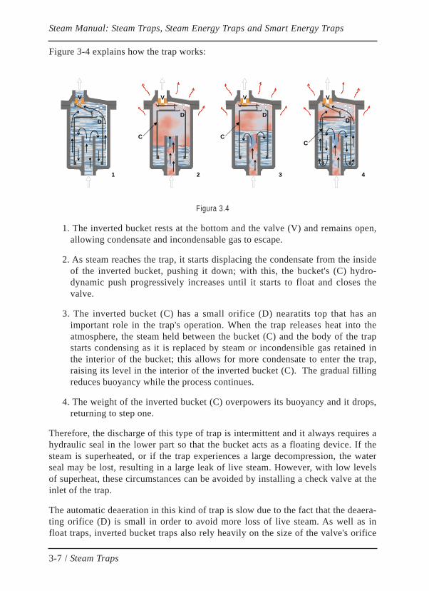
Figure 3-4 explains how the trap works:
Figura 3.4
1. The inverted bucket rests at the bottom and the valve (V) and remains open,allowing condensate and incondensable gas to escape.
2. As steam reaches the trap, it starts displacing the condensate from the insideof the inverted bucket, pushing it down; with this, the bucket's (C) hydro-dynamic push progressively increases until it starts to float and closes thevalve.
3. The inverted bucket (C) has a small orifice (D) nearatits top that has animportant role in the trap's operation. When the trap releases heat into theatmosphere, the steam held between the bucket (C) and the body of the trapstarts condensing as it is replaced by steam or incondensible gas retained inthe interior of the bucket; this allows for more condensate to enter the trap,raising its level in the interior of the inverted bucket (C). The gradual fillingreduces buoyancy while the process continues.
4. The weight of the inverted bucket (C) overpowers its buoyancy and it drops,returning to step one.
Therefore, the discharge of this type of trap is intermittent and it always requires ahydraulic seal in the lower part so that the bucket acts as a floating device. If thesteam is superheated, or if the trap experiences a large decompression, the waterseal may be lost, resulting in a large leak of live steam. However, with low levelsof superheat, these circumstances can be avoided by installing a check valve at theinlet of the trap.
The automatic deaeration in this kind of trap is slow due to the fact that the deaera-ting orifice (D) is small in order to avoid more loss of live steam. As well as infloat traps, inverted bucket traps also rely heavily on the size of the valve's orifice
3-7 / Steam Traps
Steam Manual: Steam Traps, Steam Energy Traps and Smart Energy Traps
DD
V V
1 2
C
D
V
3
C
D
V
4
C

(V) and determine the maximum working differential pressure for the trap. Conse-quently, the indications listed in float traps should be taken into considerationwhen sizing these types of elements.
The advantages characteristic of the inverted bucket trap are:
» Simplicity, with few cases of mechanical failure
» Highly resistant to water hammers
» Easily discharges dirty and oily condensate
» Low maintenance
Its main disadvantages are:
» Robust, heavy, and expensive. High indirect steam loss
» Mounting position is fixed
» Slow air venting
» Sensitive to freezing
» Does not allow for variations in its discharge temperature
» Expensive to repair, generally cannot be done while in use.
» Only allows the steam to get slightly superheated
3.6 THERMODYNAMIC DISK TRAPThis trap is notably mentionable since it has been the most used trap in the past,and it is currently considered a true "trap" from the economic stand point due to itslow energy efficiency.
From an operational point of view, it is very bad to use thermo-dynamic disk trapssince their steam losses create high local backpressure in the return line, negativelyaffecting the entire facility's operation.
Its design is very simple; it included a body (A), a cap (B), and a disk (C). (Figure3-5)
The body has two concentric annular seats, an interior one (D) around the inlet ori-fice (E) and the other on the exterior (F).
3-8 / Steam Traps
Steam Manual: Steam Traps, Steam Energy Traps and Smart Energy Traps

Between the two anular seats, there is a semicircular canal that links the orifice (S)with the trap's outlet. The cap has a protusion(H) in the middle that helps form acontrol chamber between the disk and the cap when the disk is in the highest posi-tion (open trap).
Figure 3.5
Its operation is based on the Bernoulli principle. When the trap is closed, the diskis in the lowest position, closing the two concentric seats, leaving the controlchamber closed. When the system is cold started, the trap discharges the conden-sate formed in the pipes. Once the condensate is discharged, stream reaches thetrap; at this moment, when the steam goes from inlet (E) to the outlet (S), underthe disk, the high speed movement generates an increase in dynamic pressure ofthe fluid current, which leads to the reduction in static pressure under the disk(Figure 3-6A) since the sum of both, the total pressure, sure remain constant accor-ding to the Bernouilli principle.
Figure 3.6
3-9 / Steam Traps
Steam Manual: Steam Traps, Steam Energy Traps and Smart Energy Traps
E
S
F D
E S
FDC
H
B
A
D C
(A) (B)

At the same time, a small amount of steam fills the small control chamber that isformed between the disk and the cap. The steam in the control chamber decelera-tes, and according to the Bernouilli principle, this creates an increase in static pres-sure. As a consequence of this, the disk violently descends against the trap seat,closing it. In this position, the control chamber and the inlet and outlet holes areclosed off to one another by the disk (Figure 3.6B)
In this situation, the disk is being pushed by imbalanced pressure forces since itssides are subject to the following:
a) The entire upper side of the disk faces the pressure of the control chambertrying to close the trap.
b) On the bottom side of the disk, the pressure of steam and the condensate'sbackpressure push against the parts that coincide with the orifices (E) and(S), trying to open trap.
In this imbalanced pressure situation, the closing force prevails until the controlchamber pressure lowers enough do to the condensation of the steam retainedinside, caused by heat transmission in the air around the trap's cover. Therefore,the disk will open again and repeat the cycle.
Is it important to note that the trap acts as a timer in that its discharge is cyclicallyproduced in the time that it take the retained steam to condense in the controlchamber, independently of the condensate's influx. This means than in cold areasor on rainy days, the speed at which it opens increases dramatically and causeslarge energy losses. This fact is easily proven by letting a few drops of water fallon top of the trap's cover. Protective caps are installed in order to reduce energyloss in humid climates.
Be advised that operation of this trap is sometimes mistakenly explained, affirmingthat the closing is produce by flash steam inside the trap. This is incorrect since itis live steam escape, not flash steam that generates this closing action when pas-sing through the trap (see test published in Petrogas, September 1979, page 43.)
The advantages characteristic of the thermodynamic disk trap are:
» Large pressure range
» Robust design
» Not sensitive to freezing or water hammers
» Works with superheated steam
» Low price
3-10 / Steam Traps
Steam Manual: Steam Traps, Steam Energy Traps and Smart Energy Traps
Its main disadvantages are:
» Low energy efficiency and a cyclical loss of steam, above all, in applicationswith small volumes of condensate (line and tracing drains)
» Increased backpressure in condensate return lines
» Does not allow backpressure to be higher than 60% in low pressures (80% inmedium to high pressures)
» Very sensitive to adverse climate conditions (rain and wind increase thesteam loss)
» The disk and the seat deteriorate quickly from the violent closing of the trapwhich increases the steam loss
» Low air venting capacity
» Subject to failures from buildup.
As it is shown, the disadvantages of the thermodynamic disk trap continuouslyhave an effect on its excessive energy consumption, since it has one of lowestenergy efficiencies.
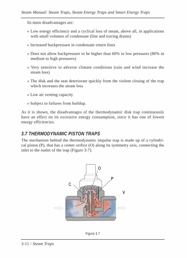
3.7 THERMODYNAMIC PISTON TRAPSThe mechanism behind the thermodynamic impulse trap is made up of a cylindri-cal piston (P), that has a center orifice (O) along its symmetry axis, connecting theinlet to the outlet of the trap (Figure 3-7).
Figure 3.7
3-11 / Steam Traps
Steam Manual: Steam Traps, Steam Energy Traps and Smart Energy Traps
C
O
P
V
The piston has a horizontal circular wing close to its upper part and it can move upand down within the cylinder, which has a conic interior (C). The lower part of thepiston closes the outlet orifice of the main valve.
The condensate that reaches the trap then borders the upper circular wing of thepiston, and it passes through the center orifice. When the condensate passesthrough the narrow area produced by the horizontal wing of the piston, it causes aload loss and consequently reduces the pressure in the upper control chamber, ontop of the piston. This way, the pressure beneath the piston's circular wing beco-mes higher than the pressure above the same wing, making the piston lift up, ope-ning the main valve.
When steam reaches the trap, the piston's center orifice generates some resistancedue to the increase in steam flow speed with respect to the flow of condensate; thiscauses the pressure in the upper control chamber to increase and the piston lowers,blocking the passage around the main valve (V).
The section that is open between the piston and the guide cylinder varies with themovement of the former as a result of the piston's conic shape, which acts as avariable size nozzle. This gives the trap some flexibility when reacting to flowvolume variations, thus making it a regulating body since the open section of themain valves depends on the piston's vertical position at every moment, and thiswill depend on the condensate flow volume in the trap.
It is important to note that the trap must always be mounted vertically in order tonot interfere with the upward and downward motion of the piston.
In order to have more operational flexibility, the trap usually has an adjustmentscrew on top which changes the position of the conic guide cylinder in order tovary the volume, and with it, the pressure of the upper control chamber.
Evidently, the trap never blocks steam as a result of the piston's center orifice andthis steam leak (control steam) is precisely what makes the trap work. This factmust be taken into consideration when inspecting this type of trap with ultrasoundequipment, since logically, the results will always detect an internal steam leak.
The advantages of this type of trap are:
» Small and robust construction
» Discharges air and incondensable gases
» Operates in a wide range of pressures and flow volumes
» Can be used with superheated steam
3-12 / Steam Traps
Steam Manual: Steam Traps, Steam Energy Traps and Smart Energy Traps
The disadvantages of this type of trap are:
» Live steam losses and low energy efficiency
» Increased backpressure and water hammers in return lines
» Fast internal wear and tear from erosion
» Sensitive to backpressure. Does not allow backpressure to exceed 40% of theworking pressure.
» Prone to drain blockage from dirt buildup
3.8 THE CURRENT USE OF STEAM TRAPSThe use of steam traps has been declining over time due to the appearance ofsteam energy traps with higher energy efficiency.
The need to reduce CO2 emission, a topic closely linked to increasing energy effi-ciency, has permanently tipped the scale in favor of steam energy traps, settingaside steam traps for use in minor applications where the requirements of the pro-cess prefer this type of equipment.
In conclusion, the appearance of the modern smart energy traps has made an uns-toppable path towards logical and intelligent energy use.
3-13 / Steam Traps
Steam Manual: Steam Traps, Steam Energy Traps and Smart Energy Traps

CHAPTER 4
ENERGY TRAPS
4.1 INTRODUCTIONAs mentioned in chapter 2, an energy trapis a mechanic element that drains auto-matically and has the ability to control the temperature of the condensate dis-charge.
Its operation exclusively depends on the energy content of the condensate, and itsregulating elements do not use control steam in order to function with high energyefficiency.
Contrary to what occurs with steam traps, the internal elements of the energy trapsdo not usually come in direct contact with steam and the condensate's flow velo-city through the valve is very low compared to that of a regular steam trap;because of this, there is much less erosion, and as a consequence, energy traps lastmuch longer in comparison with steam traps.
4.2 CLASSIFICATION OF ENERGY TRAPSThe direct relationship between the energy content of saturated steam and the satu-ration temperature leads to the use of thermostatic elements for controlling theoperation of the energy trap.
The most common types of thermostatic energy traps are:
Steam Manual: Steam Traps, Steam Energy Traps and Smart Energy Traps
4-1 / Energy Traps
TYPES OF THERMOSTATIC ENERGY TRAPS
Classic ThermostatBithermostatic
Resin
Solid Expansion Liquid Expansion Bimetallic
CapsuleBellows
According to the valve design, energy traps can be placed into two categories:
» Differential Pressure Valve
» Balanced Pressure valve
Regarding the way they function, energy controllers can be classified as:
» Cyclical discharge
» Continuous discharge
4.3 AUTOMATIC AIR VENTINGAn interesting characteristic that is common in all thermostatic energy traps is theability to automatically vent. As a result, the mixture of steam and air or inconden-sable gas, like all mixtures of gas, follows Dalton's law. Because of this, the totalpressure of the mixture is the sum of the partial pressures of its components.
So, the steam's saturation temperature in the mixture corresponds to only the par-tial pressure of the steam in it.
Therefore, a thermostatic energy trap that is subject to the action of the mixture ofsteam and incondensable gases will sense a temperature that is lower than if all ofthe fluid was steam.As a result, the energy trap will open itself and create an auto-matic vent for incondensable gases.
As the proportion of steam in the mixture increases, its temperature rises and thethermostat progressively moves the energy trap valve until it is shut, once all ofthe incondensable gases have been completely evacuated.
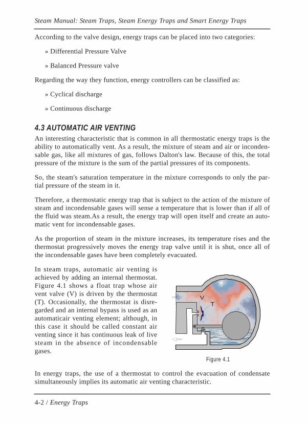
In steam traps, automatic air venting isachieved by adding an internal thermostat.Figure 4.1 shows a float trap whose airvent valve (V) is driven by the thermostat(T). Occasionally, the thermostat is disre-garded and an internal bypass is used as anautomaticair venting element; although, inthis case it should be called constant airventing since it has continuous leak of livesteam in the absence of incondensablegases.
Figure 4.1
In energy traps, the use of a thermostat to control the evacuation of condensatesimultaneously implies its automatic air venting characteristic.
Steam Manual: Steam Traps, Steam Energy Traps and Smart Energy Traps
4-2 / Energy Traps
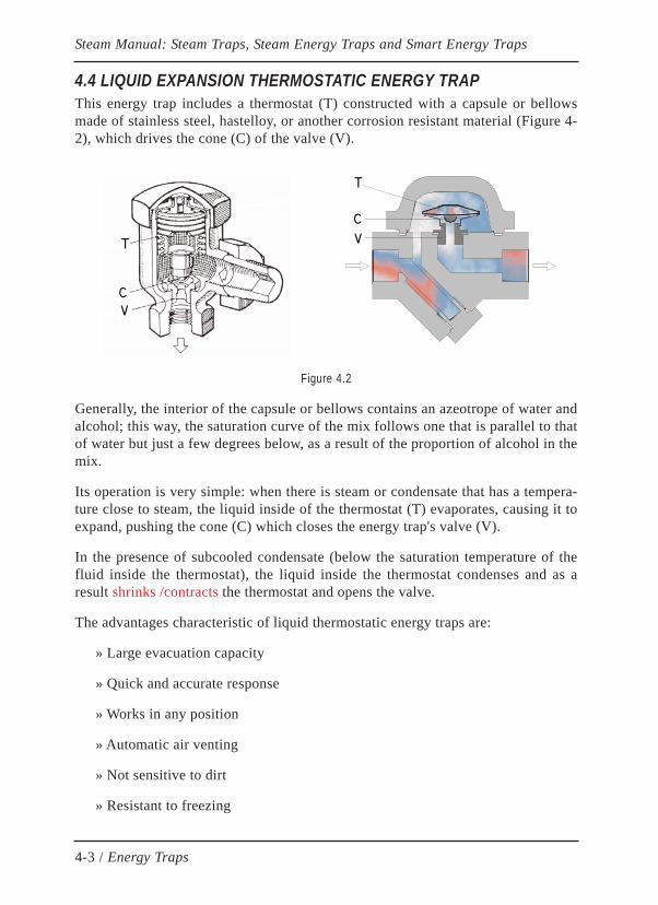
4.4 LIQUID EXPANSION THERMOSTATIC ENERGY TRAPThis energy trap includes a thermostat (T) constructed with a capsule or bellowsmade of stainless steel, hastelloy, or another corrosion resistant material (Figure 4-2), which drives the cone (C) of the valve (V).
Figure 4.2
Generally, the interior of the capsule or bellows contains an azeotrope of water andalcohol; this way, the saturation curve of the mix follows one that is parallel to thatof water but just a few degrees below, as a result of the proportion of alcohol in themix.
Its operation is very simple: when there is steam or condensate that has a tempera-ture close to steam, the liquid inside of the thermostat (T) evaporates, causing it toexpand, pushing the cone (C) which closes the energy trap's valve (V).
In the presence of subcooled condensate (below the saturation temperature of thefluid inside the thermostat), the liquid inside the thermostat condenses and as aresult shrinks /contracts the thermostat and opens the valve.
The advantages characteristic of liquid thermostatic energy traps are:
» Large evacuation capacity
» Quick and accurate response
» Works in any position
» Automatic air venting
» Not sensitive to dirt
» Resistant to freezing
Steam Manual: Steam Traps, Steam Energy Traps and Smart Energy Traps
4-3 / Energy Traps
C
T
V
C
T
V

» Allows high backpressure
» Follows the saturation curve of steam
Its main disadvantages are:
» Fragility of the thermostatic element
» Low resistance to water hammers and superheated steam
» Costly maintenance (expensive and short-lasting spare parts)
4.5 CLASSIC BIMETALLIC THERMOSTATIC ENERGY TRAPThis type uses a thermostat with bimetallic plates (T) that react according to thedifferences in the condensate's temperature, transmitting its movement to the cone(O) of the energy trap's valve (V) (Figure 4-3).
Figure 4.3
It is a very robust and versatile energy trap as it allows for the discharge tempera-ture to be adjusted to the ideal amount for the service provided or in order to opti-mize the steam network's energy efficiency.
Its operation is the following: when cold condensate reaches the energy trap, thebimetallic plates move towards a flat position, allowing for the cone to move open,which is pushed by the fluid's own pressure.
As the condensate rises in temperature, each pair bimetallic plates start to curveand expand against one another expanding like a bellows, pushing the valve coneclose against the opposing force of the pressure. The position of the valve cone,thus the opening of the valve, continually depends on the balance of opening (pres-sure) and closing (thermal) forces.
Steam Manual: Steam Traps, Steam Energy Traps and Smart Energy Traps
4-4 / Energy Traps
O
T
V

When the temperature reaches up to a few degrees below the corresponding satura-tion point of the steam, the cone hermetically seals. The closing point depends onthe adjustment set on the thermostat, which can be modified by the user.
Note that the closing is produced on the outlet side of the energy trap, where flashsteam is formed and the velocity of the fluid flow is higher. Because of this, thecone valve is subject to intense erosion which reduces the life of the energy trap.Some manufacturers have designed a stepped nozzle, in attempt to distribute thepressure jump that occurs between the inlet and outlet in stages, thus, reducing thelevel of erosion.
In reality, the bimetallic plates are not a spring, although they act as one. Theirdeformation is an intrinsic property of bimetal which takes a curved shape depen-ding on the temperature. Bimetal's operation range is maintained at all times in theelastic part of the material, far from the plastic part, in order to avoid permanentdeformations.
Each bimetallic plate is made of two alloy layers that have different thermalexpansion coefficients and high levels of Cr and Ni to prevent corrosion. There-fore, bimetallic plates always last much longer than the rest of the parts of theenergy trap.
This type of energy trap uses a differential pressure valve and an annular chamberon the outlet side where the condensate expands. This creates and additional ope-ning pressure force which increases the pressure difference that initially pushedagainst the cone valve. This reduces the bimetal's thermal hysteresis at the expenseof increasing the erosive actions of the mixture of condensate and flash steam onthe cone valve.
The advantages characteristic of the classic bimetallic energy trap are:
» High reliability, versatility, and energy efficiency
» Continuous discharge and high range of pressure
» Very robust and resistant to water hammers
» Not sensitive to corrosive condensate or freezing
» Automatic air venting and large cold-start capacity
» Works with superheated steam
» Operates in any position
Steam Manual: Steam Traps, Steam Energy Traps and Smart Energy Traps
4-5 / Energy Traps
Its main disadvantages are:
» Sensitive to dirt
» Slow response to abrupt system or pressure changes
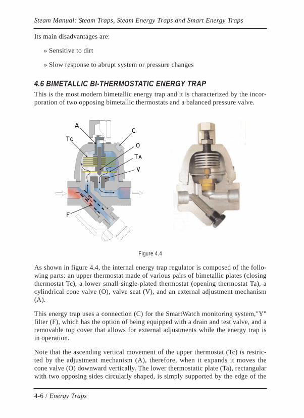
4.6 BIMETALLIC BI-THERMOSTATIC ENERGY TRAPThis is the most modern bimetallic energy trap and it is characterized by the incor-poration of two opposing bimetallic thermostats and a balanced pressure valve.
Figure 4.4
As shown in figure 4.4, the internal energy trap regulator is composed of the follo-wing parts: an upper thermostat made of various pairs of bimetallic plates (closingthermostat Tc), a lower small single-plated thermostat (opening thermostat Ta), acylindrical cone valve (O), valve seat (V), and an external adjustment mechanism(A).
This energy trap uses a connection (C) for the SmartWatch monitoring system,"Y"filter (F), which has the option of being equipped with a drain and test valve, and aremovable top cover that allows for external adjustments while the energy trap isin operation.
Note that the ascending vertical movement of the upper thermostat (Tc) is restric-ted by the adjustment mechanism (A), therefore, when it expands it moves thecone valve (O) downward vertically. The lower thermostatic plate (Ta), rectangularwith two opposing sides circularly shaped, is simply supported by the edge of the
Steam Manual: Steam Traps, Steam Energy Traps and Smart Energy Traps
4-6 / Energy Traps
OTc
V
Ta
CA
F

circular sides in a way that, as shown in the figure, does not block fluid frommoving towards the upper thermostat, always keeping the thermostats submergedin condensate to be discharged. When the lower thermostatic plate (Ta) expands, itcurves downward allowing the cone (O) to move down as well.
The following explains its operation:
With the arrival of cold condensate, the upper thermostat (Tc) contracts and thelower thermostatic plate (Ta) is flat, keeping the valve (V) completely open, allo-wing condensate to be freely evacuated.
As long as the condensate increases in temperature, the lower thermostat (Ta) cur-ves itself downward allowing the cone (O) to lower, and the upper thermostat con-tinues to expand, and therefore pushes the cone (O) downward. As a result, thecone (O) moves closer to the orifice of the valve (V), constricting the condensate'spathway.
When the temperature of the condensate reaches the amount as adjusted on theenergy trap, the cone (O) closes the valve (V) completely.
When the condensate's temperature lowers a little, the upper thermostat (Tc)slightly contracts and partially releases the closing force; at the same time, thelower thermostat (Ta) slightly reduces its curvature, lifting up the cone (O) andopening the valve (V).
Taking into account that the influx of condensate is a continuous process, the smalltemperature variations maintain a dynamic balance between both thermostats,which adjust the energy trap's discharge,to thecondensate production capacity inthe line. So, the energy trap perfectly adapts to the conditions of the process of for-ming condensate, preventing abrupt or intermittent discharges that would typicallycause water hammers in the condensate networks. Also when controlling theenergy trap's discharge temperature, the amount of flash steam produced is reducedso, as thus the level of backpressure that is present in the return line, avoiding themost serious and common cause of malfunctioning in condensate networks.
The dynamic balance point or point of operation mentioned is easily adjusted byan external adjustment mechanism (A), without the need to stop the flow of steamnor interrupt the operation of the energy trap.
Note that the cone valve as well as the thermostats are completely submerged inthe fluid, which means that the resulting pressure forces acting on themare null.That is to say, the valve is a balanced pressure valve, therefore, the energy trap'scapacity to operate and regulate is not affected by variations in the differentialpressure nor backpressure. In addition, its internal elements are subject to muchweaker mechanical stress than in the classic bimetallic energy trap.
Steam Manual: Steam Traps, Steam Energy Traps and Smart Energy Traps
4-7 / Energy Traps
The lower thermostat plays a very important role during the cold-start of theenergy trap; in fact, the cone valve can shut against excessive increases in the tem-perature of condensate in the transitory systembecause of the thermal inertia of thethermostats. Once the valve (V) shuts, pressure forces act upon the cone whichkeep it from opening, but when the temperature of the energy trap drops slightlydue to the transmission of heat with the exterior, the lower thermostat (Ta) entersinto action and lifts the cone (O) from the valve (V), reestablishing the balance offorces in the cone valve as well as the operation of the energy trap. This quicksituation only occurs in cold starts during the transitional system.
The bi-thermostatic energy trap includes four elements that make them not sensi-tive to dirt:
» "Y" Filter, with the option of including a cleaning and test valve
» Full bore valve that prevents any obstruction
» 1 mm spacers between the pairs of bimetallic plates in order to eliminate thetightening of the bimetallic packet from particle buildup between plates
» External adjustment mechanism that allows for an occasional internal blowwith the energy trap's steam, without interrupting its service
All aspects considered, the bi-thermostatic energy trap brings enough characteris-tics together in order to be currently considered one of the most robust, versatile,efficient, reliable, and low maintenance cost energy traps.
The advantages characteristic of the bimetallic bi-thermostatic energy trap are:
» Highly reliable, versatile, and energy efficient
» External adjustment mechanism, very low maintenance costs
» Continuous discharge and a wide range of pressure
» Very robust, durable, and resistant to water hammers
» Not sensitive to dirty or corrosive condensates
» Not sensitive to freezing
» Automatic air-venting and a large cold-start capacity
» Supports extremely superheated steam and very high backpressure
» Operates in any position (cone valve is guided by two separate points)
Steam Manual: Steam Traps, Steam Energy Traps and Smart Energy Traps
4-8 / Energy Traps
Its main disadvantages are:
» Produces a slight delay when there are abrupt system or pressure changes(this is not an important issue since the working conditions do not experiencesudden variations in the grand majority of applications)
4.7 CLASSIC BIMETALLIC vs. BIMETALLIC BI-THERMOSTATICAlthough both types of energy traps have already been described in sections 4.5and 4.6, given that the differences between the two have serious repercussions onoperational, energy, and maintenance areas, the most relevant differences areanalyzed below:
The first significant difference is found in the type of valve:
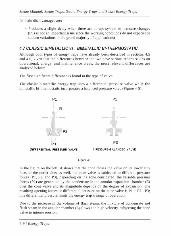
The classic bimetallic energy trap uses a differential pressure valve while thebimetallic bi-thermostatic incorporates a balanced pressure valve (Figure 4-5).
Figure 4.5
In the figure on the left, it shows that the cone closes the valve on its lower sur-face, or the outlet side; as well, the cone valve is subjected to different pressureforces (P1, P2, and P3), depending on the zone considered; the variable pressureforces (P2) are generated by the condensate in the annular expansion chamber (E)over the cone valve and its magnitude depends on the degree of expansion. Theresulting opening forces or differential pressure on the cone valve is P1 + P2 - P3;this differential pressure limits the energy trap´s range of operation.
Due to the increase in the volume of flash steam, the mixture of condensate andflash steam in the annular chamber (E) flows at a high velocity, subjecting the conevalve to intense erosion.
Steam Manual: Steam Traps, Steam Energy Traps and Smart Energy Traps
4-9 / Energy Traps
P1 P1
P3
EP2
R
P3
Pressure−balanced valveDifferential pressure valve
On the other hand, in the balanced pressure valve (figure on the right), the conecloses the valve on its upper surface, the inlet side. In addition, it is completelysubject to a uniform pressure (P1), in an area where there is no flash steam, andthus, where the fluid's velocity is low and the erosive action of the condensate onthe cone is minimal. Consequently, the lifespan of the bi-thermostatic energy trapis around three times longer than that of the classic bimetallic energy trap.
Because the resulting forces of pressure on the cone are null, the bi-thermostaticenergy trap allows for super elevated backpressure.
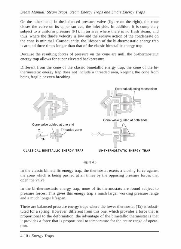
Different from the cone of the classic bimetallic energy trap, the cone of the bi-thermostatic energy trap does not include a threaded area, keeping the cone frombeing fragile or even breaking.
Figure 4.6
In the classic bimetallic energy trap, the thermostat exerts a closing force againstthe cone which is being pushed at all times by the opposing pressure forces thatopen the valve.
In the bi-thermostatic energy trap, none of its thermostats are found subject topressure forces. This gives this energy trap a much larger working pressure rangeand a much longer lifespan.
There are balanced pressure energy traps where the lower thermostat (Ta) is substi-tuted for a spring. However, different from this one, which provides a force that isproportional to the deformation, the advantage of the bimetallic thermostat is thatit provides a force that is proportional to temperature for the entire range of opera-tion.
Steam Manual: Steam Traps, Steam Energy Traps and Smart Energy Traps
4-10 / Energy Traps
CV
Threaded zone
Classical bimetallic energy trap Bi−thermostatic energy trap
Cone valve guided at both endsCone valve guided at one end
External adjusting mechanism

Figure 4-6 shows differences in guiding. The cone is guided by only one side inthe classic bimetallic energy trap, while the bi-thermostatic one is guided by both.This means that although both energy traps can work in any position, the classicdesign of the cone remains subject to asymmetrical wear and tear when it is insta-lled horizontally.
Repair of the bi-thermostatic energy trap typically consists of a simple externaladjustment in order to compensate for possible erosion on the valve cone. Howe-ver, unlike the classic bimetallic energy trap whose repair requires the replacementof the entire bimetallic regulator, if necessary, the bi-thermostatic energy trapallows for the replacement of any of its internal pieces since they are all indepen-dent (Figure 4-6) and they can be replaced separately, greatly reducing mainte-nance costs.
The mere inspection of the state of wear and tear in the valve is impossible in aclassic bimetallic energy trap without disassembling the regulator itself. On theother hand, the bi-thermostatic energy trap has easy access to all of its parts oncethe cover is removed, without the need to use tools or remove the regulator adjus-tment as it remains in the adjustment screw that is secured to the cover.
Finally, as it is logical, the direction of the flow in an energy trap is indicated on itsown body and it should not be inverted as the energy trap would become blocked.But if this occurs unintentionally, the bi-thermostatic energy trap is so reliable thatit will continue to function in this situation, though the closing action of the valvewould be produced in the outlet side like in the classic bimetallic energy trapexcept that the thermostat would now be located on the outlet side.
4.8 TRAP VALVE STATIONThe trap valve station is an element that is widely used in new projects for its redu-ced size, low cost, and easy mounting.
Generally, a TVS (Figure 4-7) is made up of a combination of all of the elementsthat form a classic drain station, including:
» Inlet and outlet isolation valves
» Drain Valve
» Test Valve
» Universal connection
» Energy trap (or steam trap) with universal connector
Steam Manual: Steam Traps, Steam Energy Traps and Smart Energy Traps
4-11 / Energy Traps
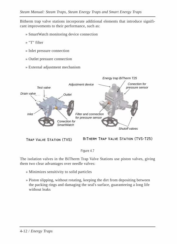
Bitherm trap valve stations incorporate additional elements that introduce signifi-cant improvements to their performance, such as:
» SmartWatch monitoring device connection
» "T" filter
» Inlet pressure connection
» Outlet pressure connection
» External adjustment mechanism
Figure 4.7
The isolation valves in the BiTherm Trap Valve Stations use piston valves, givingthem two clear advantages over needle valves:
» Minimizes sensitivity to solid particles
» Piston slipping, without rotating, keeping the dirt from depositing between the packing rings and damaging the seal's surface, guaranteeing a long life without leaks
Steam Manual: Steam Traps, Steam Energy Traps and Smart Energy Traps
4-12 / Energy Traps
Inlet
Conection forpressure sensor
Conection forSmartWatch
Energy trap BiTherm T25
Adjustment device
Trap Valve Station (TVS)
Filter and connectionfor pressure sensor
Shutoff valves
BiTherm Trap Valve Station (TVS−T25)
Test valve
Drain valve Outlet

CHAPTER 5
INTELLIGENT ENERGY TRAPS AND VALVES
5.1 INTELLIGENT ENERGY TRAPThe genuine Intelligent Energy Trap, known as SmartWatchWebTM (in shortSWW), was internationally patented by BiTherm on 1996. SWW basically con-sists of three main elements (figure 5.1):
a) Bi-Thermostatic Energy Trap with external adjustment mechanism
b) Non-invasive Electronic Monitor Device (SWW)controlled by microprocessor
c) Graphical User Interface (GUI)
Figure 5.1
Steam Manual: Steam Traps, Energy Traps and Intelligent Traps
Balancedpressurevalve
SmartWatch device
Upperbimetallicthermostat
External adjustment mechanism
Filter cleaning valve
Independentscone and seat
“Y” Strainer
External mounting( Noninvasive )
Lowerbimetallicthermostat
5-1 / Steam: Basic Concepts
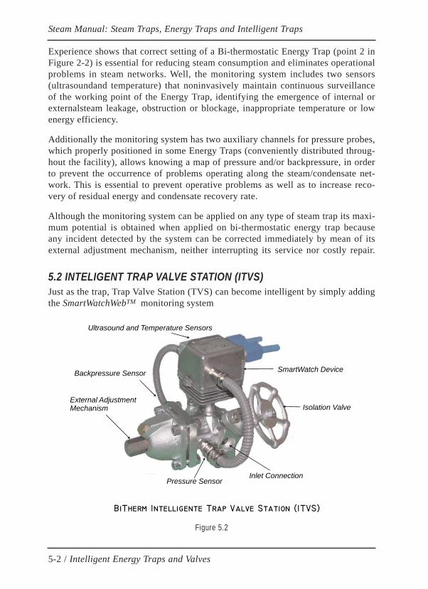
Experience shows that correct setting of a Bi-thermostatic Energy Trap (point 2 inFigure 2-2) is essential for reducing steam consumption and eliminates operationalproblems in steam networks. Well, the monitoring system includes two sensors(ultrasoundand temperature) that noninvasively maintain continuous surveillanceof the working point of the Energy Trap, identifying the emergence of internal orexternalsteam leakage, obstruction or blockage, inappropriate temperature or lowenergy efficiency.
Additionally the monitoring system has two auxiliary channels for pressure probes,which properly positioned in some Energy Traps (conveniently distributed throug-hout the facility), allows knowing a map of pressure and/or backpressure, in orderto prevent the occurrence of problems operating along the steam/condensate net-work. This is essential to prevent operative problems as well as to increase reco-very of residual energy and condensate recovery rate.
Although the monitoring system can be applied on any type of steam trap its maxi-mum potential is obtained when applied on bi-thermostatic energy trap becauseany incident detected by the system can be corrected immediately by mean of itsexternal adjustment mechanism, neither interrupting its service nor costly repair.
5.2 INTELIGENT TRAP VALVE STATION (ITVS)Just as the trap, Trap Valve Station (TVS) can become intelligent by simply addingthe SmartWatchWebTM monitoring system
Figure 5.2
Steam Manual: Steam Traps, Energy Traps and Intelligent Traps
5-2 / Intelligent Energy Traps and Valves
Backpressure Sensor
Pressure SensorInlet Connection
SmartWatch Device
Isolation ValveExternal AdjustmentMechanism
BiTherm Intelligente Trap Valve Station (ITVS)
Ultrasound and Temperature Sensors

As shown in Figure 5.2, Intelligent Trap Valve Station (BiTherm ITVS) has allnecessary connections to monitor the four parameters controlled by the Smart-WatchWebTM system (ultrasound, temperature, pressure and backpressure); thus itis possible to monitor the steam/condensate network without the need for subse-quent connections into pipes.
It is interesting to note that it is not necessary install a pressure sensor per steamtrap to get reliable map of back pressure along the whole condensate network, butinstalling only a few pressure sensors conveniently distributed along the network isenough to get that goal.
Although the possibility of monitoring is not addressed in new projects, the use ofmonitorable BITHERM Trap Valve Stations brings great value to the project sinceit allows this future option, reducing installation costs.
5.3 DESCRIPTION AND ARCHITECTURE OF THE SWW SYSTEMSmartWatchWebTM is a digital monitoring system based on microprocessor. Theirdevices are organized in a hierarchical structure, which exchange information bidi-rectionally via a field data bus. These electronic devices are divided into threebasic levels:
» At the lowest level of the system there are the field devices that incorporateor are connected to the corresponding sensors.
» The second level consists of control units or concentrators that collect infor-mation from the field devices and transmit it to the next level.
» The third level is the control center where all information is managed.
Depending on the physical media used the system supports two possible options:
» Wired data bus RS-485 (Figure 5.3)
» Wireless network (Figure 5.4)
The wired data bus can cover a distance of 1200 meters (limitation imposed by theRS-485 specification, which can be expanded conveniently by placing controlunits or installing signal amplifiers) and supports up to 125 field devices, fourchannels per device , i.e.up to 500 sensors. The range of the wireless networkdepends on factors such as location of antennas, power emitted by antennas,absorption of radiated power by nearest elements to antennas (ground, concretepillars, etc.) so it is advisable to conduct a radiofrequency survey on site beforedeploying a wireless network in order to detect potential problems and to locateradio transmitters conveniently.
Steam Manual: Steam Traps, Energy Traps and Intelligent Traps
5-3 / Intelligent Energy Traps and Valves

Figure 5.3
Figure 5.4
Steam Manual: Steam Traps, Energy Traps and Intelligent Traps
5-4 / Intelligent Energy Traps and Valves
Up to 125 SWW devices per loop
Windows PC platform with wired data bus RS−485
SWW Device
Up to 250 loops
Control Center
Control Unit
SmartWatch wireless network)
SWW RFWirelessDevice
Control Center
Gateway
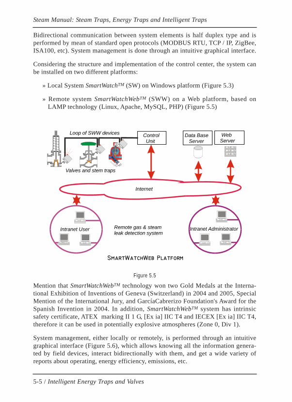
Bidirectional communication between system elements is half duplex type and isperformed by mean of standard open protocols (MODBUS RTU, TCP / IP, ZigBee,ISA100, etc). System management is done through an intuitive graphical interface.
Considering the structure and implementation of the control center, the system canbe installed on two different platforms:
» Local System SmartWatchTM (SW) on Windows platform (Figure 5.3)
» Remote system SmartWatchWebTM (SWW) on a Web platform, based onLAMP technology (Linux, Apache, MySQL, PHP) (Figure 5.5)
Figure 5.5
Mention that SmartWatchWebTM technology won two Gold Medals at the Interna-tional Exhibition of Inventions of Geneva (Switzerland) in 2004 and 2005, SpecialMention of the International Jury, and GarcíaCabrerizo Foundation's Award for theSpanish Invention in 2004. In addition, SmartWatchWebTM system has intrinsicsafety certificate, ATEX marking II 1 G, [Ex ia] IIC T4 and IECEX [Ex ia] IIC T4,therefore it can be used in potentially explosive atmospheres (Zone 0, Div 1).
System management, either locally or remotely, is performed through an intuitivegraphical interface (Figure 5.6), which allows knowing all the information genera-ted by field devices, interact bidirectionally with them, and get a wide variety ofreports about operating, energy efficiency, emissions, etc.
Steam Manual: Steam Traps, Energy Traps and Intelligent Traps
5-5 / Intelligent Energy Traps and Valves
SmartWatchWeb Platform
Intranet User Intranet Administrator
Internet
Remote gas & steamleak detection system
Control Unit
Loop of SWW devices
Valves and stem traps
Data Base Server
WebServer
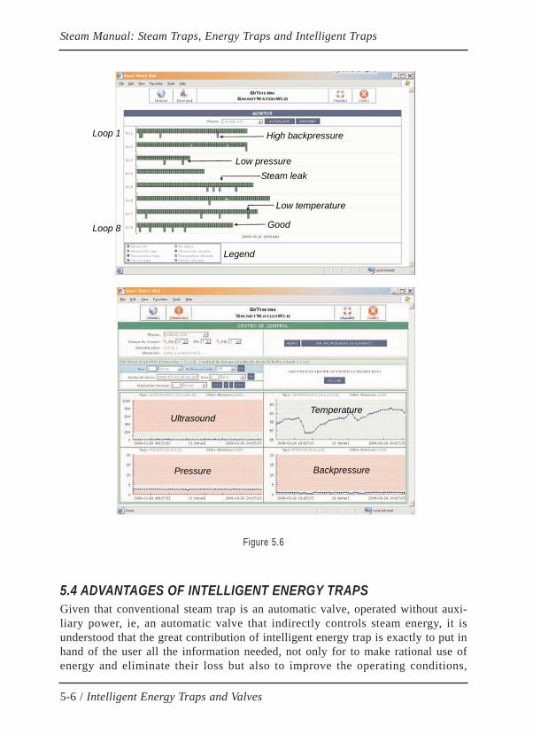
Figure 5.6
5.4 ADVANTAGES OF INTELLIGENT ENERGY TRAPSGiven that conventional steam trap is an automatic valve, operated without auxi-liary power, ie, an automatic valve that indirectly controls steam energy, it isunderstood that the great contribution of intelligent energy trap is exactly to put inhand of the user all the information needed, not only for to make rational use ofenergy and eliminate their loss but also to improve the operating conditions,
Steam Manual: Steam Traps, Energy Traps and Intelligent Traps
5-6 / Intelligent Energy Traps and Valves
Loop 1
Loop 8
High backpressure
Low pressureSteam leak
Low temperature
Good
Legend
UltrasoundTemperature
Pressure Backpressure
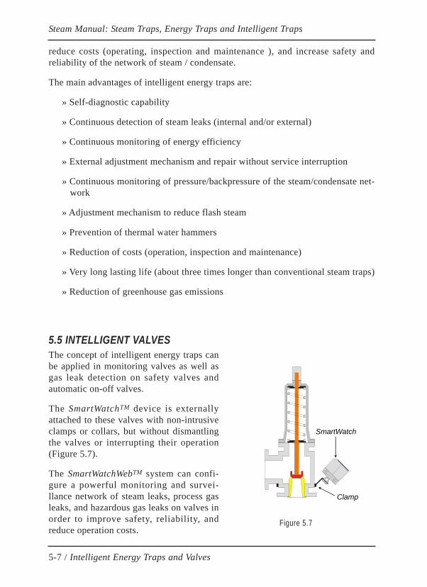
reduce costs (operating, inspection and maintenance ), and increase safety andreliability of the network of steam / condensate.
The main advantages of intelligent energy traps are:
» Self-diagnostic capability
» Continuous detection of steam leaks (internal and/or external)
» Continuous monitoring of energy efficiency
» External adjustment mechanism and repair without service interruption
» Continuous monitoring of pressure/backpressure of the steam/condensate net-work
» Adjustment mechanism to reduce flash steam
» Prevention of thermal water hammers
» Reduction of costs (operation, inspection and maintenance)
» Very long lasting life (about three times longer than conventional steam traps)
» Reduction of greenhouse gas emissions
5.5 INTELLIGENT VALVES The concept of intelligent energy traps canbe applied in monitoring valves as well asgas leak detection on safety valves andautomatic on-off valves.
The SmartWatchTM device is externallyattached to these valves with non-intrusiveclamps or collars, but without dismantlingthe valves or interrupting their operation(Figure 5.7).
The SmartWatchWebTM system can confi-gure a powerful monitoring and survei-llance network of steam leaks, process gasleaks, and hazardous gas leaks on valves inorder to improve safety, reliability, andreduce operation costs.
Steam Manual: Steam Traps, Energy Traps and Intelligent Traps
5-7 / Intelligent Energy Traps and Valves
SmartWatch
Clamp
Figure 5.7

The system monitors continuously, detecting any leakage of gas as soon as itoccurs; once the leak has been detected, the control center automatically transmitsthe alarm to the appropriate departments, which can then act immediately and takethe corrective action in order to eliminate hazardous situations and reduce the riskof accidents (Figure 5-8).
Figure 5.8
Therefore, the following objectives are achieved:
» Detection of internal and external leakage of process gases in order to reduceproduction costs
» Fast detection of hazardous gas leaks in order to significantly improve safetyconditions on facilities
» Reduction of inspection costs
» Reduction of deterioration from gas and steam leaks in valves on account offast leak detection (reduction of maintenance costs)
Figure 5-9 shows the application of SmartWatchWebTM in monitoring automaticon-off valves for instant detection of process gas leaks that otherwise could be bur-ned on flare without identification. Thus, process losses are reduced and therefore,so are production costs as well as inspection costs and maintenance costs.
Steam Manual: Steam Traps, Energy Traps and Intelligent Traps
5-8 / Intelligent Energy Traps and Valves
SmartWatch device
Continuous surveillance 24/365
Remote alarm Alarm SafetyDepartment
Alarm Maintenance Department
Control center
Dangerousgas leak

Figura 5.9
A remarkable feature of the SmartWatchWebTM system is its ability to integratemultiple types of sensors in a common architecture that can grow as new needsarise. Therefore, steam traps, valves and other equipment can share a commonarchitecture, simplifying operations and reducing costs.
5.6 STEAM SAVING WITH ENERGY TRAPSExperience shows that the correct setting of the operating point of the energy trap(point 2 of the curve in Figure 2-2) leads to significant energy savings.
In petrochemical plants and refineries, the vast majority of traps are installed inlow flow applications (tracers, drip legs, ...) where an optimal adjustment of theworking point of the energy trap reduces up to 8% steam consumption.
Steam Manual: Steam Traps, Energy Traps and Intelligent Traps
5-9 / Intelligent Energy Traps and Valves
Monitored On-Off valves on process plants
Continuous surveillance 24/365
Remote alarm Alarm SafetyDepartment
Alarm Maintenance Department
Control center
Gas leak

CHAPTER 6
DESIGN OF STEAM AND CONDENSATE NETWORKS
6.1 INTRODUCTION
The high energy content of steam and its easy transformation into other forms ofenergy makes steam an element that is widely used in a large amount of industrialapplications.
Steam is most widely used as a thermal carrier in industrial processes that requireheat input as in heat exchangers, heating radiators, piping for product lines, etc.
Another application that is very economically important consists in converting itsinternal energy into mechanical energy for moving turbines, which is then conver-ted into electric energy by alternators. In other applications, this mechanicalenergy is used to directly drive pumps or compressors.
Steam's internal energy can be converted into kinetic energy which is used, amongother applications, in steam ejector based on the Venturi effect.
Other applications use steam as a chemical compound in chemical reactors, whichis involved in the reaction or is used as a means of agitating tanks and mixers.
Logically, different points of use of steam are usually placed far from others and ata distance from where steam is produced, which is why it is absolutely essential tohave a distribution pipe network that carries it to each equipment that requiressteam. Figure 2-1 is a visual representation of a typical steam facility.
First, there is a boiler that converts chemical energy from the fuel into heat energy.By means of an interchanging pipe system, the heat is transferred to the water thatis contained inside the boiler until it causes the water to evaporate.
The steam generated is sent to the various points of use through a pipe system thatmakes up the distribution network.
DESIGN OF STEAM AND CONDENSATE NETWORKS
6-1 / Design of steam and condensate networks

The energy content of the steam is extracted by adequate equipment using methodsthat are the most appropriate for each process, thus, causing the steam to condenseas a result of this release of energy.
The water formed is evacuated to a tank through another pipe network that makesup the condensate return line system. At this point, it is pumped back into the boi-ler where it will restart the same cycle.
The diagram described corresponds to a closed system where water changes tosteam then back to water again, repeating this cycle without losing mass. Differentfrom this, if condensate produced in the steam using equipmentis not sent back tothe boiler, but instead it is evacuated to the outside of the facility, this correspondsto an open circuit system.
It is evident that the closed system is more efficient than the open one, since theresidual energy of the condensate (sensible heat) is returned and reused in the boi-ler. However, the presence of steam loss through leaks and vents or the existenceof equipment in the facility that uses steam mass (ejectors, bubble agitators, sootblowers, mixers, deaerators, etc.) make the facilities, in practice, not closed enti-rely but rather almost closed.
The loss of water mass in an open system can be more problematic than the energycost of steam in areas that are difficult to supply.
During the start of a facility, the equipment and pipes may contain air. The air orother non-condensable gases produced in the steam generation process reduce thesteam's temperature, and they are poor heat transmitters, making it necessary to beevacuated through adequate air vents.
The steam distribution and condensate return network, subject to environmentalconditions, release heat to the outside through transmission and radiation, resultingin energy loss or auto-consumption, which can be reduced by thermally isolatingpipes, equipment, and accessories.
The circulation of steam and condensate through the inside of the piping is sloweddown by the friction of the walls of the pipes, causing a loss of pressure. In thesteam, this pressure loss translates into a decrease in temperature as shown in thesteam saturation curve (Figure 1-3). This pressure loss by friction is known as apressure drop.
The temperature differences on the piping create expansions and contractions,generating considerable mechanical stress on the structure. This stress is strongenough to cause breakage and therefore must be avoided. In order to do this,expansion joints and dilatation lira are used in those sections where the installationitself is unable to absorb the expansions.
DESIGN OF STEAM AND CONDENSATE NETWORKS
6-2 / Design of steam and condensate networks
The differences in circulation velocity between steam and condensate are capableof producing obstructions in the pipes known as water hammers (mechanical); themix of condensate and flash steam originating from different pressures of steamcan also cause water hammers (thermal), which significantly damage all of thefacility's elements, causing breakage and leaks. Water hammers are heard as loudmetallic cracks or hammer blows in the pipes.
6.2 GENERAL STEAM DISTRIBUTION LINESThe design of steam distribution lines must take the following factors into conside-ration:
» Auto consumption of steam. Energy loss
» Sizing and flow velocity
» Structural calculations: mechanical stress, expansions, etc
The sizing of a steam distribution network always begins with the understanding ofsteam consumption for each piece of equipment that makes up the facility. The cal-culations must always include an adequate safety factor that gives certain flexibi-lity to the operation of all of the equipment and the facility as a whole. It isrecommended to size the network with at least 20% of the capacity reserved forfuture expansions or modifications.
Additionally, identifying the network layout allows us to first estimate the approxi-mate diameter required, which will be explained in a later section. Now, the net-work itself consumes its own steam because of releasing energy to the outside.These losses depend on thermal insulation and the surface of the pipes. Auto-con-sumption must be taking into account, increasing the total steam flow transportedby the pipes, thus resulting in a recalculation of the distribution network's finaldiameter.
It is very common to use different steam pressures in different equipment at thesame facility. Because of this, steam is often generated at pressures that surpass theworking amount, only to be lowered at the points of use. This is usually beneficialsince there is a pressure margin for future needs, which also means a reduction inthe diameters of pipes, valves, or network accessories (reduction in installation andmaintenance costs), although their thickness increases (rise in costs), which is whyit is necessary to determine the most favorable solution.
It is also important to recall that the correct choice of working pressure in heatexchanging equipment influences its thermal efficiency; this can be seen in theenthalpy-pressure curve shown in figure 1-4. Note that as long as the pressureincreases, so does the sensible heat of the liquid; at the cost of lowering the latent
DESIGN OF STEAM AND CONDENSATE NETWORKS
6-3 / Design of steam and condensate networks

heat of vaporization used in the heat exchange processes, therefore requiring moresteam in order to produce the same amount of energy. However, the pressure ofsteam must not drop below a certain limit in order to guarantee the process of heattransmission.
This minimum limit is theoretically fixed by the process's temperature that deter-mines the saturation temperature of steam, and with it, the theoretic pressure thres-hold. Twenty percent above this amount is usually enough to achieve favorableconditions for transmitting heat with high thermal efficiency.
For calculations of steam facilities, this manual uses simple and quick graphics,based on empirical laws that are widely confirmed by experience, which offer realsolutions that are very close to those gathered through more elaborate methods.
6.3 NETWORK AUTO-CONSUMPTIONThe least favorable situation or the case that has the most auto-consumption is pro-duced during the start-up of the facility, since the pipes are cold and must warm-upuntil they reach the system's temperature.
After this temperature, the pipes continue releasing energy through conduction,convection and radiation to the outside, but the condensation generated by theseenergy losses is generally much less than during the facility's start-up.
The amount of steam needed to put a facility into operation comes from the follo-wing equation:
Qs = P * (Ts - Ta) * Cp / CL
Where:Qs = Amount of steam in KgP = Total weight of the pipes and accessories in KgTs = Steam temperature in CelsiusTa = Outside air temperature in CelsiusCp = Specific heat of steel = 0.114 Kcal / ºC KgCL = Latent heat of the steam in Kcal / Kg
This amount of steam Qs will correspond to an hourly flow rate, increasing as theheating time or start-up time gets shorter.
DESIGN OF STEAM AND CONDENSATE NETWORKS
6-4 / Design of steam and condensate networks
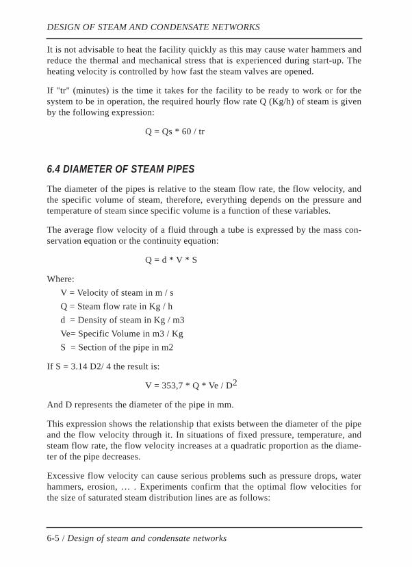
It is not advisable to heat the facility quickly as this may cause water hammers andreduce the thermal and mechanical stress that is experienced during start-up. Theheating velocity is controlled by how fast the steam valves are opened.
If "tr" (minutes) is the time it takes for the facility to be ready to work or for thesystem to be in operation, the required hourly flow rate Q (Kg/h) of steam is givenby the following expression:
Q = Qs * 60 / tr
6.4 DIAMETER OF STEAM PIPES
The diameter of the pipes is relative to the steam flow rate, the flow velocity, andthe specific volume of steam, therefore, everything depends on the pressure andtemperature of steam since specific volume is a function of these variables.
The average flow velocity of a fluid through a tube is expressed by the mass con-servation equation or the continuity equation:
Q = d * V * S
Where:V = Velocity of steam in m / sQ = Steam flow rate in Kg / hd = Density of steam in Kg / m3Ve= Specific Volume in m3 / KgS = Section of the pipe in m2
If S = 3.14 D2/ 4 the result is:
V = 353,7 * Q * Ve / D2
And D represents the diameter of the pipe in mm.
This expression shows the relationship that exists between the diameter of the pipeand the flow velocity through it. In situations of fixed pressure, temperature, andsteam flow rate, the flow velocity increases at a quadratic proportion as the diame-ter of the pipe decreases.
Excessive flow velocity can cause serious problems such as pressure drops, waterhammers, erosion, … . Experiments confirm that the optimal flow velocities forthe size of saturated steam distribution lines are as follows:
DESIGN OF STEAM AND CONDENSATE NETWORKS
6-5 / Design of steam and condensate networks
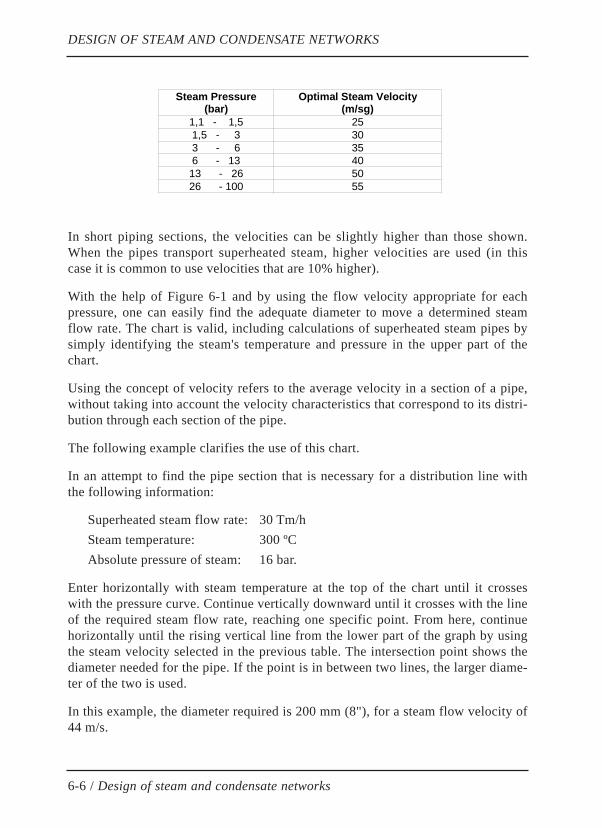
In short piping sections, the velocities can be slightly higher than those shown.When the pipes transport superheated steam, higher velocities are used (in thiscase it is common to use velocities that are 10% higher).
With the help of Figure 6-1 and by using the flow velocity appropriate for eachpressure, one can easily find the adequate diameter to move a determined steamflow rate. The chart is valid, including calculations of superheated steam pipes bysimply identifying the steam's temperature and pressure in the upper part of thechart.
Using the concept of velocity refers to the average velocity in a section of a pipe,without taking into account the velocity characteristics that correspond to its distri-bution through each section of the pipe.
The following example clarifies the use of this chart.
In an attempt to find the pipe section that is necessary for a distribution line withthe following information:
Superheated steam flow rate: 30 Tm/hSteam temperature: 300 ºCAbsolute pressure of steam: 16 bar.
Enter horizontally with steam temperature at the top of the chart until it crosseswith the pressure curve. Continue vertically downward until it crosses with the lineof the required steam flow rate, reaching one specific point. From here, continuehorizontally until the rising vertical line from the lower part of the graph by usingthe steam velocity selected in the previous table. The intersection point shows thediameter needed for the pipe. If the point is in between two lines, the larger diame-ter of the two is used.
In this example, the diameter required is 200 mm (8"), for a steam flow velocity of44 m/s.
DESIGN OF STEAM AND CONDENSATE NETWORKS
6-6 / Design of steam and condensate networks
Steam Pressure (bar)
Optimal Steam Velocity (m/sg)
1,1 - 1,5 25 1,5 - 3 30 3 - 6 35 6 - 13 40 13 - 26 50 26 - 100 55
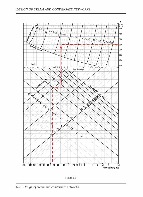
Figure 6.1
DESIGN OF STEAM AND CONDENSATE NETWORKS
6-7 / Design of steam and condensate networks
10
0 9090 80 70 60
50 40 35 30 2520 18 16 14 12
10 9 8 7 65
4 3,5 3 2,52
1,8
9
1,6 1,4 1,2 0,91 0,8 0,7 0,60,5
450
350
300
250
200
400
150
1000,15
(º C)T
0,20,30,40,50,60,811,5234567891015203040506070Kg/m
700 mm
Flow velocity m/s 100300 200 150 80 60 50 40 30 20 15 10 9 8 7 6 5 4 3 2 1,5 1 0,5
600550500450400
100
200
300
75
5040
3225
250
350
150
10080
6050
4030
2015
108
6 54
32
10,8
0,60,5
0,4
0,2
0,1
3
Abso
lute p
ressu
re ba
r
Specific weight
Saturated steam
Pipe diameterStea
m flowrate T
/h

Once the pipe diameter is determined, other important aspects of the design of thefacility must be taken into consideration, whether they are mechanical, thermal,operational, structural, or other aspects, such as:
» Pressure Drops
» Pipe dilatation
» Slopes
» Thermal loss and insulation
» Draining and Venting Points
» Structural strength calculations
6.5 CONDENSATE RETURN LINESThe condensate return lines have a few similarities and differences with regards tothe steam's distribution lines.
The first difference that can be observed is that one drives steam while the other,condensate; this gives them different flow velocities to take into account whensizing the corresponding sections of pipes.
However, the condensate return line does not only move water but also flashsteam. This is a consequence of the differential pressure in the diverse drainingsystems, causing the formation of a certain amount of flash steam (see section 1.3).
Note that the flash steam has the same properties as live steam; the only differencebetween them is how they originate, so, in order to size the condensate return line,it can be considered a transversal double-sectioned pipe. Water will circulatethrough the bottom section and low pressure steam will circulate through the uppersection.
Now, experience shows that fairly good results come from sizing return lines as ifthey were steam distribution lines (first, disregarding water flow as an approxima-tion of the actual solution) only by taking into account the following observations:
» Use the maximum amount of flash steam formed for the flow design
» Use a flow velocity of 15 m/s for this flash steam
» Prove the validity of this simplification
DESIGN OF STEAM AND CONDENSATE NETWORKS
6-8 / Design of steam and condensate networks

Actually, in order to find the exact size of the section needed for the condensatereturn line, the water flow section must be calculated first, and then the steamphase section.
Due to the differences in viscosity between both phases, the flow velocity of eachmust be different; when significant, this difference can cause little waves along thesurface of the separation of the phases (Figure 6-2), and eventually cause momen-tary blockage of the entire pipe section, primarily in direction or section changes,which results in undesirable water hammers that are harmful to the facility. Inorder to avoid water hammers, the appropriate flow velocities should be around 2m/s for liquid and between 15 and 20 m/s for steam.
Figure 6.2
Now, with such a low flow velocity for the steam phase and the large volume thatrepresents a small percentage of revaporized water compared with the total flowvolume in the return line, the section that is needed to move the additional liquidturns out negligible in front of the section required for the steam phase. The com-mercial pipe diameter available determines the closest choice because of excess inthe market-excess that is usually much larger than the section needed to drive theliquid phase.
Because of all of this, it seems practical to utilize the calculation simplificationhypothesis mentioned, since, in practice the results rarely differ from those obtai-ned with the most precise calculations.
Use chart 1-7 to calculate the amount of flash steam.
6.6 PRESSURE DROPSPressure drops in fluids moving through a turbulent pipe can most frequently becalculated using the Darcy Equation:
Pc = k *( L * d * V2)/ ( D * 104 * 2g)
DESIGN OF STEAM AND CONDENSATE NETWORKS
6-9 / Design of steam and condensate networks
Steam 15 m/s
Water 2 m/s

Where:Pc = Pressure drop (Kg/cm2) or (bar)k = Friction CoefficientL = Piping length (m) D = Piping diameter (m)d = Steam density (Kg/m3)V= Flow velocity (m/s)g = acceleration of gravity (9,81 m/s2)
The factor of 104 is introduced in order to represent the result in Kg/cm2 (in barsapproximately).
The following equation is use frequently:
Pc = kv *(d * V2)/ (104 * 2g)
The coefficient kv is commonly used in valves and accessories, which representconcentrated pressure drops. Usually, all concentrated pressure drops are groupedtogether in the coefficient kv, as the sum of all of the individual kv.
The total pressure drop happens to be the sum of all of the concentrated pressuredrops plus that caused by the piping itself.
In order to apply these formulas, the pipe friction coefficient (k) must be known,which depends on the relative roughness of the pipe and the Reynolds number.Common in all practical cases, for turbulent flow and from Reynolds in the orderof 106, the friction coefficient (k) takes an almost constant value. An averageacceptable value is k = 0.0206.
A sufficiently approximated calculation can be carried out with the help of thegraphs in Figures 6-3 and 6-4, as described below:
» Use the graph in Figure 6-3 to obtain the pressure drop coefficients (k) for thepiping, valves, and accessories.
» Add all of the coefficients corresponding to all of the elements that make upthe steam distribution line in order to determine the total pressure drop coef-ficient.
» Use the total pressure drop coefficient obtained before, and apply it to thegraph in Figure 6-4 to finally find the total pressure drop (in bars).
DESIGN OF STEAM AND CONDENSATE NETWORKS
6-10 / Design of steam and condensate networks
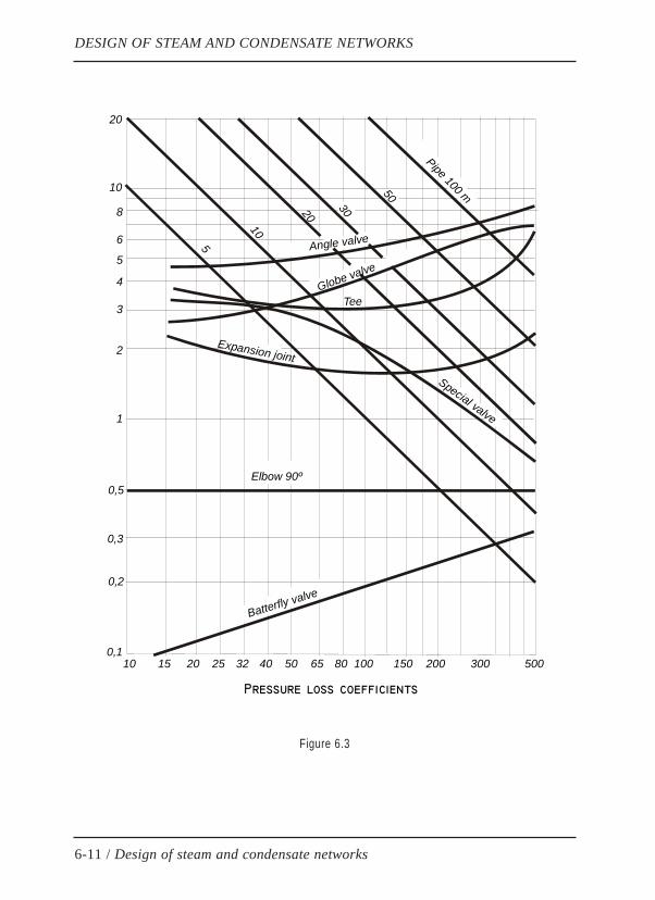
Figure 6.3
DESIGN OF STEAM AND CONDENSATE NETWORKS
6-11 / Design of steam and condensate networks
Tee
0,1
0,2
0,3
0,5
1
10 15 20 25 32 40 50 65 80 100 150 200 300 500
2
3
4
5
6
8
10
20
Elbow 90º
Globe valve
Batterfly valve
Expansion joint
5
10
20
30
50
Pipe 100 m
Special valve
Angle valve
Pressure loss coefficients
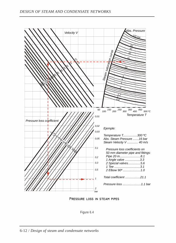
Figure 6.4
DESIGN OF STEAM AND CONDENSATE NETWORKS
6-12 / Design of steam and condensate networks
2
Pressure loss in steam pipes
bar
1
0,5
0,3
0,2
0,1
0,05
0,03
0,02
0,01
21,51
34 5 6 8
10 15 2030 40 50
Pressure loss coefficient
Velocity V
10 m/s15
202530405060708090100120140
Stea
m s
atur
atio
n cu
rve
Abs. Pressure
0,811,2
2
345
10
20
5040
30
100 bar
Temperature T
50100 200 300 400 500 ºC
150 250 350 450
Ejemple:
Temperature T.................300 ºCAbs. Steam Pressure .......16 barSteam Velocity V ............. 40 m/s Pressure loss coefficients on 50 mm diameter pipe and fittings: Pipe 20 m.........................8.1 1 Angle valve ..................3.3 2 Special valves...............5.6 1 Tee ...............................3.1 2 Elbow 90º .....................1.0
Total coefficient ..................21.1
Pressure loss ......................1.1 bar

6.7 PIPE EXPANSIONDuring the start-up of the steam facility, the pipes expand as they continue gettingcloser to the temperature of a continuous regimen. The increase in length of thepipes caused by the temperature can be determined by using the graph in Figure 6-5, applicable for steel pipes commonly used in facilities (carbon content between0.1% and 0.2%).
Figure 6.5
DESIGN OF STEAM AND CONDENSATE NETWORKS
6-13 / Design of steam and condensate networks
0Pipe length (m)
Expansion of steel pipes
Expansion of the pipe (m)
60
70
80
90
120
110
100
10 20 30 40 50500
450
400
350
300
265300
200
150
100
50
50 100 156 200 300 400
Tem
pera
ture
d (º
C)
iffer
ence

This heat expansion, or dilatation, is absorbed by various types of compensators,some of which are pre-manufactured and must be selected using the manufacturer'sdirections, and others are constructed out of piping elements such as elbows andliras.
In the situation that the pipes change direction, the elbows can be sized in a waythat they absorb the dilatation experienced by the pipes in accordance with thefollowing expression, valid for pre-compressed elbows with 50% of the expansionabsorbed.
L = 0,063 (f * D)1/2
Where:L = Length of the elbow arms (m)f = Dilatation absorbed by the elbow (mm)D = Diameter of the exterior of the pipe (mm)
This expression is represented graphically in Figure 6-6.
Figure 6.6
DESIGN OF STEAM AND CONDENSATE NETWORKS
6-14 / Design of steam and condensate networks
Expansion absorbed by carbon steel elbows 50% precompressed
Pipe diameter ND (mm)40
Req
uire
d le
nght
on
elbo
w b
ranc
hes
(m)
60 80 100
L
5
6
7
8
9
10
120 160 200 250 300 400
12
14
16
18
20
30
Fixetpoint
Expansion absorbed f = 400 mm
f = expansion (mm) D = pipe diameter (mm) L = lenght of elbow branches (m)
40
6080
100150
200250300350
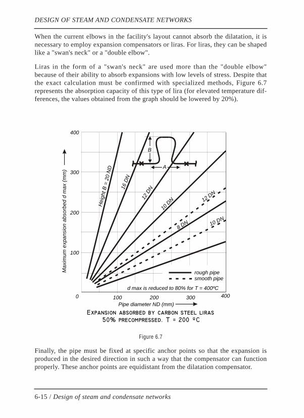
When the current elbows in the facility's layout cannot absorb the dilatation, it isnecessary to employ expansion compensators or liras. For liras, they can be shapedlike a "swan's neck" or a "double elbow".
Liras in the form of a "swan's neck" are used more than the "double elbow"because of their ability to absorb expansions with low levels of stress. Despite thatthe exact calculation must be confirmed with specialized methods, Figure 6.7represents the absorption capacity of this type of lira (for elevated temperature dif-ferences, the values obtained from the graph should be lowered by 20%).
Figure 6.7
Finally, the pipe must be fixed at specific anchor points so that the expansion isproduced in the desired direction in such a way that the compensator can functionproperly. These anchor points are equidistant from the dilatation compensator.
DESIGN OF STEAM AND CONDENSATE NETWORKS
6-15 / Design of steam and condensate networks
Expansion absorbed by carbon steel liras 50% precompressed. T = 200 ºC
Pipe diameter ND (mm)
Max
imum
exp
ansi
on a
bsor
bed
d m
ax (m
m)
100
A
200 300 400
rough pipesmooth pipe
B
d max is reduced to 80% for T = 400ºC
100
200
300
400
0
Hei
ght B
= 2
0 N
D
16 D
N
12 D
N
10 D
N 12 DN
10 DN8 DN
6.8 SLOPESAll of the piping in the facility should have a positive slope in the direction of theflow in order to allow it to be emptied by gravity. This helps prevent possiblewater pockets caused by the pipe deflection produced between two consecutivepiping supports.
The pipes are usually angled with a 2% gradient; any less will allow for the forma-tion of the aforementioned water pockets, which cause corrosion in the pipes. Ifthere is a negative gradient (an upward slope), the condensate may flow backwardsdue to the force of gravity, opposite that of steam, potentially causing water ham-mers due to blocking the pipes; this is most common with small diameter pipes,damaged heat insulators, or in low pressure steam facilities.
6.9 SUPPORTSIts purpose is to rigidly support the pipes, or to allow for them to expand longitudi-nally or laterally, thus, helping the mission of the elbow and lira dilatation com-pensators. The large variety of current pipe supports can be separated into threetypes:
» Normal supports
» Anchors
» Lateral guide supports
Normal Supports:
They are regularly spaced along the pipes and allow for longitudinal movementand sometimes, lateral movement. They are frequently used in the shape of evenrollers (cylinders) that allow for lateral movement, arranged over beam supports orsuspended by a roof or another fixed structure.
Anchors:
Their purpose is to provide pipe immobilization at fixed points. They are made offlanges that are secured by screws that connected the pipe to an adequate fixedstructure. Their calculation must consider resistance in order to support the forcesnot only from the pipe's weight, but also from the thermal mechanical stress thatcause heat expansion in the pipes and any other additional load that may act onthem during the facility's service, as well as start-up and shut-down.
Lateral Guide Supports:
As the name indicates, lateral guide supports allow for the pipe to move laterally,but they also leave the pipes free to move longitudinally.
DESIGN OF STEAM AND CONDENSATE NETWORKS
6-16 / Design of steam and condensate networks

6.10 THERMAL WATER HAMMERSIn general, a water hammer is understood as a sudden and significant pressureincrease or pressure wave that usually reaches values of around 150% of the nor-mal operating pressure. This pressure wave displaces at the velocity of soundinside the fluid, which can cause elastic deformations, plastic deformations, andbreakage in the facility's elements.
Water hammers are recognized by loud cracks, metallic hits, noises, and vibrationin the facility. They must be separated into two different classes of water hammers,although they can sometime occur simultaneously.
» Hydraulic water hammers in liquid facilities
» Thermal water hammers in steam and condensate lines
The first are generally caused as a result of the sudden opening or closing of val-ves or when the valves themselves operate very quickly.
The second type of water hammers are cause by sudden condensation of steambubbles inside a mass of condensate with a much lower temperature, thus, produ-cing what can be considered an "implosion". These implosions get stronger the lar-ger the bubbles are or the faster their condensation occurs (larger temperaturedifference between flash steam and condensate).
It is not easy to calculate the overpressure produced in thermal water hammers, butit is obvious that their intensity depends on the size of the steam bubbles, the velo-city of water and steam, and their temperature difference.
Thermal water hammers can occur as a result of inadequate sizing of equipment orpiping, poor selection of draining devices or defective steam traps and energytraps, internal steam leaks in the draining devices, improper installation or place-ment of these elements, or a combination of all of these.
In any case, water hammers must be avoided starting at the design of the facilitywith respect to a series of regulations, some of which are listed below:
» Limit the use of steam traps to when they are absolutely necessary
» Install energy traps before pipe elevations
» Install energy traps at the lowest point of the facility
» Transport condensate originating from steam of a very different pressure inindependent lines; if this is not possible, water hammer compensators shouldbe installed and strategically placed
DESIGN OF STEAM AND CONDENSATE NETWORKS
6-17 / Design of steam and condensate networks
» Avoid condensate elevations after the draining elements, and when it is inevi-table, use water hammer compensators if water hammers occur
» In order to reduce the potential intensity of water hammers, equip the dis-charge pipe with holes or openings that distribute the steam in small bubblesin situations where the return line arrives to a condensate tank at a lowerlevel than the liquid
Preventing thermal water hammers:
The best way to prevent thermal water hammers is with the use of intelligentenergy traps. With them, internal steam leaks can be detected immediately and itsenergy efficiency can be monitored and adjusted, which effectively prevents theoccurrence of water hammers.
DESIGN OF STEAM AND CONDENSATE NETWORKS
6-18 / Design of steam and condensate networks
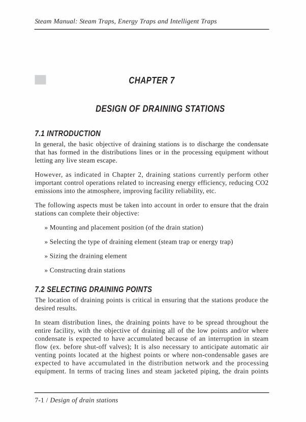
CHAPTER 7
DESIGN OF DRAINING STATIONS
7.1 INTRODUCTIONIn general, the basic objective of draining stations is to discharge the condensatethat has formed in the distributions lines or in the processing equipment withoutletting any live steam escape.
However, as indicated in Chapter 2, draining stations currently perform otherimportant control operations related to increasing energy efficiency, reducing CO2emissions into the atmosphere, improving facility reliability, etc.
The following aspects must be taken into account in order to ensure that the drainstations can complete their objective:
» Mounting and placement position (of the drain station)
» Selecting the type of draining element (steam trap or energy trap)
» Sizing the draining element
» Constructing drain stations
7.2 SELECTING DRAINING POINTSThe location of draining points is critical in ensuring that the stations produce thedesired results.
In steam distribution lines, the draining points have to be spread throughout theentire facility, with the objective of draining all of the low points and/or wherecondensate is expected to have accumulated because of an interruption in steamflow (ex. before shut-off valves); It is also necessary to anticipate automatic airventing points located at the highest points or where non-condensable gases areexpected to have accumulated in the distribution network and the processingequipment. In terms of tracing lines and steam jacketed piping, the drain points
Steam Manual: Steam Traps, Energy Traps and Intelligent Traps
7-1 / Design of drain stations
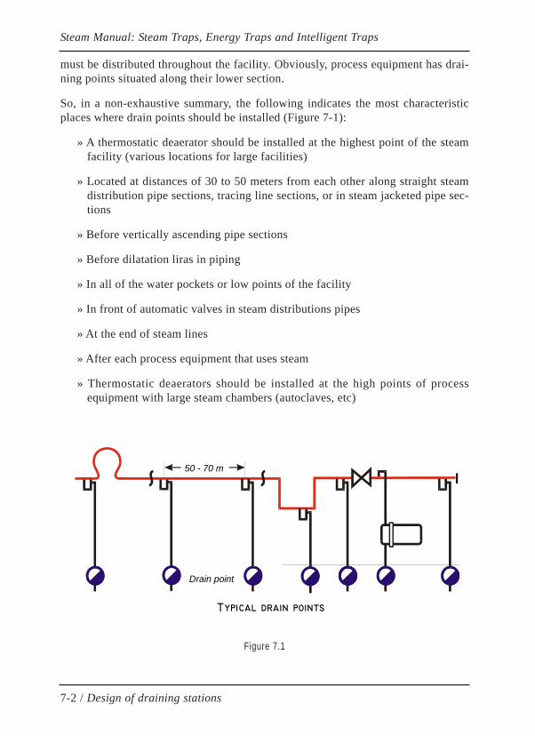
must be distributed throughout the facility. Obviously, process equipment has drai-ning points situated along their lower section.
So, in a non-exhaustive summary, the following indicates the most characteristicplaces where drain points should be installed (Figure 7-1):
» A thermostatic deaerator should be installed at the highest point of the steamfacility (various locations for large facilities)
» Located at distances of 30 to 50 meters from each other along straight steamdistribution pipe sections, tracing line sections, or in steam jacketed pipe sec-tions
» Before vertically ascending pipe sections
» Before dilatation liras in piping
» In all of the water pockets or low points of the facility
» In front of automatic valves in steam distributions pipes
» At the end of steam lines
» After each process equipment that uses steam
» Thermostatic deaerators should be installed at the high points of processequipment with large steam chambers (autoclaves, etc)
Figure 7.1
Steam Manual: Steam Traps, Energy Traps and Intelligent Traps
7-2 / Design of draining stations
Typical drain points
Drain point
50 - 70 m

7.3 SELECTING THE TYPE OF DRAINING ELEMENTSelecting the type of drain element is primarily determined by the characteristicsof the processing equipment for draining or the application; but other aspects mustbe considered, such as the characteristics of the facility, work and environmentconditions, energy efficiency, reliability and availability, ease of inspection andmaintenance, robustness, lifespan, resistance to failures, and finally, its cost.
Therefore, the first decision to make is in selecting the type of drain element; thereare two basic options:
» Steam Trap
» Energy Trap
It is usually recommended to use steam traps when it is necessary to ensure thatthere is absolutely no condensate in front of the trap, without considering the faci-lity's energy efficiency. In this situation, the effects of the rise in flash steam in thedischarge of the trap should be assessed in order to prevent any consequences(backpressure, thermal water hammers). Thermodynamic disk traps are used toevacuate small and medium steam flows, while inverted bucket traps and floattraps are used for large steam flows.
It is recommended to use energy traps when it is necessary to increase the energyefficiency of a facility by reducing steam consumptions, and with it, CO2 emis-sions as well as improving the operation of condensate return lines, avoiding back-pressure and thermal water hammers. The evolution of thermostatic energy trapsalways provides a satisfactory solution for each application; to evacuate small andmedium steam flows, bimetallic and bi-thermostatic energy traps are used, whilemulti-element thermostatic energy traps are used for large steam flows. For tracingapplications, the most appropriate type is the bimetallic thermostatic energy trap,preferably the bi-thermostatic energy trap due to its external regulation mechanis-mthat allow for the most benefits.
When choosing the drain element, an aspect that should be considered is themethod to be employed for future inspection and maintenance. The rising use ofintelligent energy traps simplifies the inspection tasks and reduces energy andmaintenance costs. However, even when the use of intelligent steam traps is notanticipated, it is advisable to design a drain stations in a way that allows for aneasy incorporation of additional elements for future monitoring (SwartWatch con-nection, pressure and backpressure sensor connections), and in this way the costswould be reduced when the conventional stations are updated to intelligent drai-ning stations.
Just as the energy trap is implicitly related to its automatic air-venting capacity,when steam traps are used, thermostatic air-venting elements should be included in
Steam Manual: Steam Traps, Energy Traps and Intelligent Traps
7-3 / Design of draining stations
order to prevent possible blockage caused by air or non-condensable gases. It isrecommended to avoid using internal by-bass orifices as automatic air vents, sincethey create a continuous steam loss that is injected into the return lines, causingproblems.
Sizing the Drain Element:
Once the type of draining element has been decided, it needs to be sized; in orderto do this, the following aspects must be taken into account:
» Maximum pressure and temperature of the design
» Maximum operational differential pressure
» Minimum operational differential pressure
» Maximum steam flow to be evacuated in low differential pressure conditions
» Optimal condensate evacuation temperature
» Safety factor
» Type of connection
The design's maximum pressure and temperature determine the materials of thedraining element in accordance with the manufacturer's instructions.
The draining element must be able to function properly up to the maximum opera-tional differential pressure. Note that energy traps may lose steam when the diffe-rential pressure exceeds the maximum amount indicated by the manufacturer; onthe contrary, float traps and inverted bucket traps remain blocked when the diffe-rential pressure exceeds the amount indicated by the manufacturer.
The size of the draining element is imposed by the maximum steam flow to eva-cuate, including safety factors and in situations of minimum differential pressure.It is not advisable to utilize exaggerated safety coefficients since over-sizing isharmful to the element's regulatory operation and it reduces its lifespan. It is worthpointing out that steam traps require greater safety factors than energy traps, sincethe latter have an intrinsic safety coefficient that superimposes the one measuredby the user. Typical values for this coefficient are from 2.5 to 3 for steam traps and1.5 to 2 for energy traps.
When considering the discharge capacity of a draining element, the steam flowcurves provided by the manufacturer have to be used. There is no uniformity in theway of presenting these curves, and therefore, while some offer cold condensateflow information, others refer to condensate flow at the condensate's boiling tem-
Steam Manual: Steam Traps, Energy Traps and Intelligent Traps
7-4 / Design of draining stations
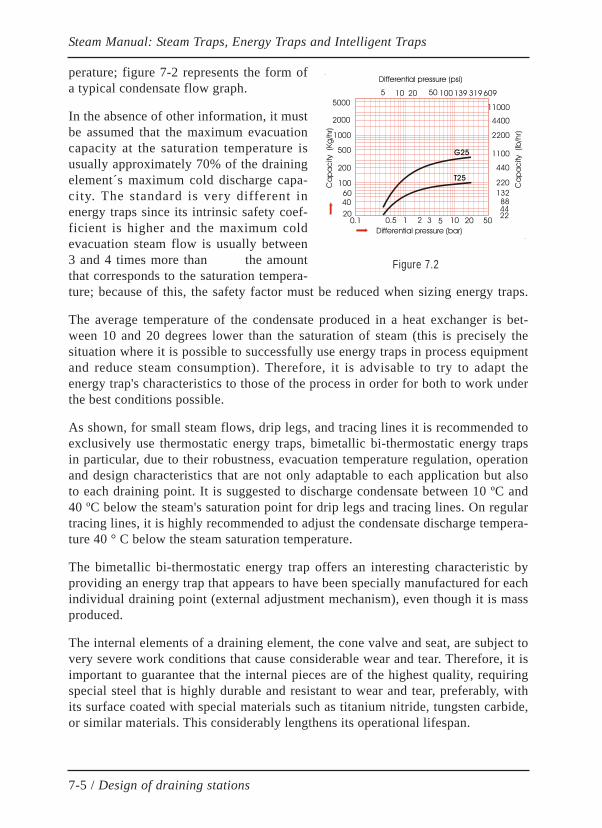
perature; figure 7-2 represents the form ofa typical condensate flow graph.
In the absence of other information, it mustbe assumed that the maximum evacuationcapacity at the saturation temperature isusually approximately 70% of the drainingelement´s maximum cold discharge capa-city. The standard is very different inenergy traps since its intrinsic safety coef-ficient is higher and the maximum coldevacuation steam flow is usually between3 and 4 times more than the amountthat corresponds to the saturation tempera-ture; because of this, the safety factor must be reduced when sizing energy traps.
The average temperature of the condensate produced in a heat exchanger is bet-ween 10 and 20 degrees lower than the saturation of steam (this is precisely thesituation where it is possible to successfully use energy traps in process equipmentand reduce steam consumption). Therefore, it is advisable to try to adapt theenergy trap's characteristics to those of the process in order for both to work underthe best conditions possible.
As shown, for small steam flows, drip legs, and tracing lines it is recommended toexclusively use thermostatic energy traps, bimetallic bi-thermostatic energy trapsin particular, due to their robustness, evacuation temperature regulation, operationand design characteristics that are not only adaptable to each application but alsoto each draining point. It is suggested to discharge condensate between 10 ºC and40 ºC below the steam's saturation point for drip legs and tracing lines. On regulartracing lines, it is highly recommended to adjust the condensate discharge tempera-ture 40 ° C below the steam saturation temperature.
The bimetallic bi-thermostatic energy trap offers an interesting characteristic byproviding an energy trap that appears to have been specially manufactured for eachindividual draining point (external adjustment mechanism), even though it is massproduced.
The internal elements of a draining element, the cone valve and seat, are subject tovery severe work conditions that cause considerable wear and tear. Therefore, it isimportant to guarantee that the internal pieces are of the highest quality, requiringspecial steel that is highly durable and resistant to wear and tear, preferably, withits surface coated with special materials such as titanium nitride, tungsten carbide,or similar materials. This considerably lengthens its operational lifespan.
Steam Manual: Steam Traps, Energy Traps and Intelligent Traps
7-5 / Design of draining stations
Differential pressure (bar)
Ca
pa
city
(K
g/h
r)
0.1 0.5 1 2 3 5 10 20 5020
60
100
40
200
500
1000
2000
5000
Differential pressure (psi)
5 10 20 50 100 139 319 609
Ca
pa
city
(lb
/hr)
22
11000
4400
2200
1100
440
220
1328844
T25
G25
Figure 7.2
Take into account that a draining element with a robust design that uses specialmaterials in the components will mean a higher purchasing price, but this is tho-roughly compensated by its high reliability, long life, and energy savings.
The draining element's possibility of including an external adjustment mechanismraises the final price, but the enormous advantages in energy savings, easy mainte-nance, versatility, etc, offered by this mechanism undoubtedly put to rest any eco-nomic comparisons with elements that lack the mechanism.
Occasionally the draining element must withstand temperatures below zero. This isthe case for facilities with intermittent operations, which can leave them filled withcondensate when the outside temperature is below zero degrees. In these situa-tions, the draining element is required to be durable enough to support freezes, set-ting aside those that are constructed from iron casts or that have sensitive internalelements. Additional, in this situation the drain element design must favor auto-draining the facility into the atmosphere; this will keep a facility safe against free-zes.
In situations where thermal water hammers are expected to form from dischargingcondensates of different pressures to a shared condensate return line, sensitive ele-ments of the energy traps should be discarded, such as floats and capsules or liquidexpansion bellows. Here, the most adequate are the bimetallic followed by theinverted bucket elements.
It is preferable to use float traps or inverted bucket traps when the condensate isvery dirty or oily. In the situation that another type of element is used, it is conve-nient to have a filter (a "Y" filter if possible) with a drain valve to help clear anypotential obstruction of the element.
Ideally, the draining element has a good air-venting capacity during start-up andregular operation. The most common automatic air-venting mechanism is the ther-mostat, which should be bimetallic due to its robustness against liquid expansion.
Some float traps have permanent venting holes with the purpose of creating auto-matic air venting. These types of vents must only be used in applications thatrequire it in order to avoid the formation of a "steam jam", like draining rotatingcylinder dryers with a siphon. In all other situations, this type of vent is a source ofunnecessary energy loss.
Lastly, choosing the type of connection has an impact on future steam leaks in thefacility. There is no doubt that the most dependable connection against leaks iswelding, although the flanged connection offers high reliability and easier mainte-nance. In tracing facilities with a large number of draining stations, it is normal touse the threaded, the cheapest but with frequent leaks throughout pipe accessories
Steam Manual: Steam Traps, Energy Traps and Intelligent Traps
7-6 / Design of draining stations

such as connecting nuts. Angular and non-standardized connections should beavoided as they implicate a dependency on a manufacturer.
Although it is risky to provide recommendations regarding the type of drainingelement for each application, the following shows certain guidelines that help faci-litate the selection, limiting the wide variety of possibilities, in descending order ofpriority:
Application: Tracing, radiators, and jacketed pipes
» Bi-thermostatic with external temperature adjustment
» Bimetallic
» Thermostatic
» Other type
Application: Drip legs and line ends
» Bi-thermostatic with external temperature adjustment
» Bimetallic
» Thermostatic
» Float
» Inverted Bucket
» Other type
Application: Steam blowers and turbine protectors
» Bi-thermostatic with external temperature adjustment
» Inverted bucket when the superheated steam level allows
» Thermodynamic
» Impulse
» Other type
Application: Tanks, water heaters, heat exchangers
» Bi-thermostatic with external temperature adjustment, when steam flowallows
Steam Manual: Steam Traps, Energy Traps and Intelligent Traps
7-7 / Design of draining stations
» Thermostatic, when the steam flow allows, and/or multi-element
» Float
» Inverted Bucket
» Other type
Application: Autoclaves and sterilizers
» Float
» Inverted Bucket
» Thermostatic, when the steam flow allows
» Thermodynamic
» Other type
Application: Air heaters
» Bi-thermostatic with external temperature adjustment
» Bimetallic
» Thermostatic
» Float
» Other type
Application: rotating cylinder dryers
» Special energy traps and automatic wastepipe valves
» Float
» Inverted Bucket
» Other type
Application: Vulcanizers and flat presses
» Inverted Bucket
» Float
» Thermodynamic
Steam Manual: Steam Traps, Energy Traps and Intelligent Traps
7-8 / Design of draining stations
» Bi-thermostatic with external temperature adjustment, when steam flowallows
» Thermostatic
» Other type
Application: Air heaters and hot air dryers
» Bimetallic
» Thermostatic
» Float
» Inverted bucket
» Other type
Application: Evaporators and beer distilleries
» Float
» Inverted bucket
» Bimetallic
» Thermostatic
» Other type
Application: Steam irons and laundry grills
» Bi-thermostatic with external temperature adjustment, when steam flowallows
» Float
» Inverted bucket
» Thermodynamic
» Other type
Other than a few exceptions, note that thermodynamic traps rarely appear in theprevious recommendations due to the fact they have very low energy efficiency asa consequence of its principle of operation.
Steam Manual: Steam Traps, Energy Traps and Intelligent Traps
7-9 / Design of draining stations

Recall that the size of the draining element is not determined by the diameter ofthe connection, but rather the diameter of the internal orifice of the valve, which issized for the maximum steam flow to evacuate and the minimum possible differen-tial pressure.
In the petrochemical industry, the two most expansive applications are tracing orheavy material heating and drip legs in steam distribution lines. In both cases, theoperation steam flows in a continuous regimen are almost always less than 50Kg/h (generally they do not exceed 10 Kg/h). So, in situations of the reduced flowas mentioned, any small steam leak results in an extremely high percentage ofenergy loss; therefore, it is essential to use draining elements that thoroughly gua-rantee that the steam is hermetically sealed and that the condensate discharge iscarried out by controlling its temperature, which leads to the necessity to use bi-thermostatic energy traps in both applications.
In order to facilitate the selection of BiTherm energy traps, use the computer tool"Energy Trap Selection Software", available in the following link:
http://www.smartwatchweb.com
7.4 CONSTRUCTION OF DRAINING STATIONSThe construction of a draining station differs according to its application; the follo-wing are the most common:
Automatic Air Venting Points:
Air venting points are located at the highest points of the facility, close to steamgenerators when possible. They are constructed by implanting a 1 to 2 meter longpipe section, 3/4" to 1" in diameter, at an ascending angle, with a thermostaticenergy trap or air vent at the end. At the outlet of the energy trap, a piece of pipe inthe shape of a swan's neck is connected in order to prevent dripping on the energytrap itself. The air-venting pipe and theenergy trap itself must remain withoutthermal insulation in order to assisttheir air-venting function.
Drip Legs in Steam DistributionLines:
Drip legs are designed in such a waythat gravity causes the condensate toenter in order to be removed by thedraining element (Figure 7-3).
Steam Manual: Steam Traps, Energy Traps and Intelligent Traps
7-10 / Design of draining stations
Steam Line
10"4"
1/2"-3/4"3/4"
Energy Trap
D
D
Figure 7.3

As a general rule, the depth of a drip leg usually spans between 250 mm and 700mm (the depth increases as the differential pressure drops) and its section, up to 4",typically coincides with the diameter of the pipe itself. Beyond 4", the drip leg dia-meter is slightly reduced. The largest section of the drip leg must never exceed10", no matter the situation.
At the bottom of the drip leg, a descending vertical connection is implanted with adraining and cleaning valve; this valve is 3/4" in drip legs up to 2", 1" in drip legsthat measure 2.1/2" or 3", 1.1/2" for diameters larger than 3" but less than 10", and2" for drip legs with diameters 10" and above.
At 3/4 of the height of the drip leg from its base, a horizontal draining pipe isimplanted and measures 1/2" or 3/4" according to the user's standard.
When condensate has to be elevated after the draining element, up to the returnline, it is advisable to do so in accordance with the diagram in Figure 7-4.
If condensate is elevated before the draining element, a small siphon should beplaced before the elevation in order to prevent water hammers (Figure 7-5).
In addition to the draining element,draining stations must contain ele-ments that make the maintenance pro-cess easier (filters, isolation valves,and when necessary, bypass valves),but the current tendency is to use com-pact draining stations known as TVS(Trap Valve Stations) which, in addi-tion to the draining element, incorpo-rate all of the previously mentionedvalves as shown in Figure 7-6.
Steam Manual: Steam Traps, Energy Traps and Intelligent Traps
7-11 / Design of draining stations
Wrong elevation of condensate after a trap
Steam trap
BetterGood
Correct elevation of condensate after a trap
Figure 7.4 Figure 7.5
Figure 7.6
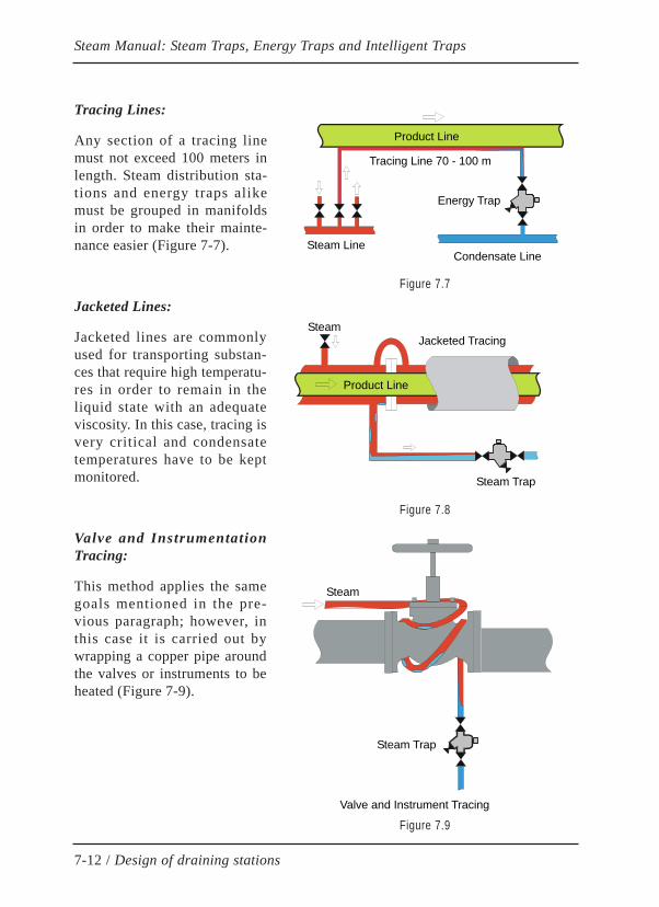
Tracing Lines:
Any section of a tracing linemust not exceed 100 meters inlength. Steam distribution sta-tions and energy traps alikemust be grouped in manifoldsin order to make their mainte-nance easier (Figure 7-7).
Jacketed Lines:
Jacketed lines are commonlyused for transporting substan-ces that require high temperatu-res in order to remain in theliquid state with an adequateviscosity. In this case, tracing isvery critical and condensatetemperatures have to be keptmonitored.
Valve and InstrumentationTracing:
This method applies the samegoals mentioned in the pre-vious paragraph; however, inthis case it is carried out bywrapping a copper pipe aroundthe valves or instruments to beheated (Figure 7-9).
Steam Manual: Steam Traps, Energy Traps and Intelligent Traps
7-12 / Design of draining stations
Product Line
Tracing Line 70 - 100 m
Energy Trap
Condensate LineSteam Line
Product Line
Steam Trap
Jacketed TracingSteam
Steam Trap
Steam
Valve and Instrument Tracing
Figure 7.7
Figure 7.8
Figure 7.9

Process Equipment Draining:
When draining process equipment, the drip leg must have a vertical descendingdistance between the equipment and the energy trap of between 300 and 700 mm,selecting the drain pipe diameter and the diameter of the energy trap itself inaccordance with the capacity of condensate to be evacuated, differential pressure,design safety factor, and any other condition imposed by the design.
In situations where there are special conditions like bottom coils with condensateelevations before the energy trap (Figure 7-10), bottom siphons need to be used inorder to prevent water hammers.
In process equipment with large spaces for steam and/or frequent starts and stops,it is necessary to prevent automatic air venting at the equipment's high points inorder to avoid the presence of non-condensable gases that would reduce the stea-m's partial pressure (Dalton's Law), along with its saturation temperature, affectingthe thermal efficiency of the heating process. A thermostatic energy trap can beused as an automatic air vent. Note that in these situations it is not sufficient tohave an energy trap with automatic air venting capabilities located at the bottom,since the air and non-condensable gases in the upper area of the equipment wouldnever reach the bottom energy trap, making it necessary to install an air vent at thetop. The air vent must be installed at end of the vertical ascending pipe at least 1meter in length, coming to an end in the shape of a swan´s neck behind the energytrap, without any thermal insulation.
If the condensate flow to be evacuated in the equipment is unknown, follow therule of selecting the energy trap diameter that is one step lower than the diameter
Steam Manual: Steam Traps, Energy Traps and Intelligent Traps
7-13 / Design of draining stations
Steam Trap
Syphon
Bath
Steam Trap
Air vent
Sterilizer
Figure 7.10 Figure 7.11
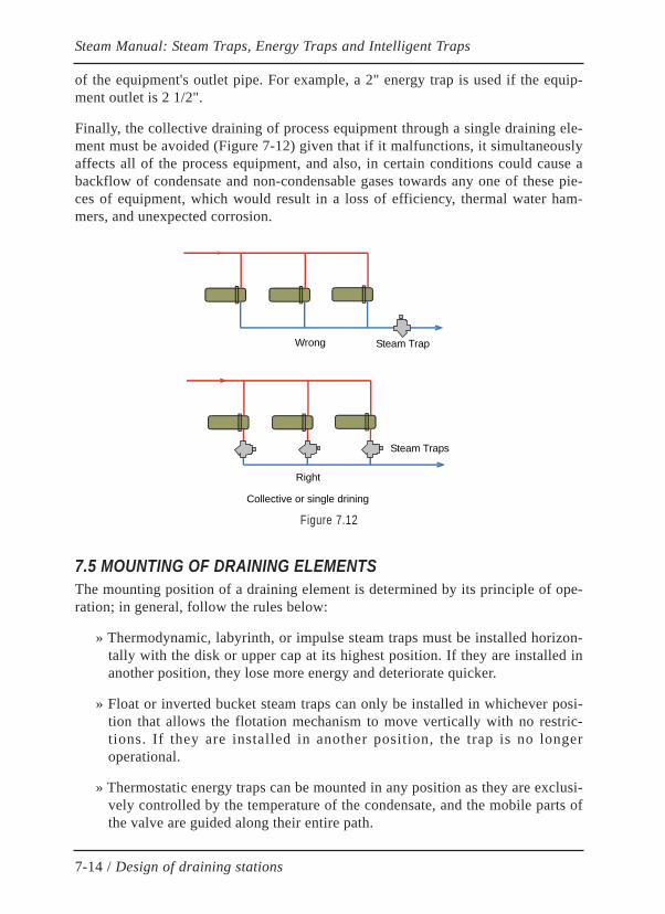
of the equipment's outlet pipe. For example, a 2" energy trap is used if the equip-ment outlet is 2 1/2".
Finally, the collective draining of process equipment through a single draining ele-ment must be avoided (Figure 7-12) given that if it malfunctions, it simultaneouslyaffects all of the process equipment, and also, in certain conditions could cause abackflow of condensate and non-condensable gases towards any one of these pie-ces of equipment, which would result in a loss of efficiency, thermal water ham-mers, and unexpected corrosion.
7.5 MOUNTING OF DRAINING ELEMENTSThe mounting position of a draining element is determined by its principle of ope-ration; in general, follow the rules below:
» Thermodynamic, labyrinth, or impulse steam traps must be installed horizon-tally with the disk or upper cap at its highest position. If they are installed inanother position, they lose more energy and deteriorate quicker.
» Float or inverted bucket steam traps can only be installed in whichever posi-tion that allows the flotation mechanism to move vertically with no restric-tions. If they are installed in another position, the trap is no longeroperational.
» Thermostatic energy traps can be mounted in any position as they are exclusi-vely controlled by the temperature of the condensate, and the mobile parts ofthe valve are guided along their entire path.
Steam Manual: Steam Traps, Energy Traps and Intelligent Traps
7-14 / Design of draining stations
Wrong
Right
Steam Trap
Steam Traps
Collective or single drining
Figure 7.12

Draining stations are usually mounted in groups in a compact design, but it isworth considering easy access and handling at each draining element in order to beable to easily carry out future inspection and maintenance operations.
In some applications it may be useful to install a sightglass upstream of the drai-ning element in order to be able to observe its operation; but, it must be taken intoaccount that the sightglass is an element that requires maintenance to clean the dirtfrom its window. However, the same effect may be achieved through the use ofmonitoring the drain element just as described in section 8.3.
Due to the evolution of the draining station inspection systems, the use of ultra-sound makes it unnecessary to install test valves on the draining stations themsel-ves.
In the same way, the problems generated by improper maneuvering of by-pass val-ves (pressurization in return lines), together with the advances in the energy trapdesign with external adjustment mechanisms, are contributing to eliminations ofby-pass valve, except in process equipment drains or highly critical drains wherethey must be conserved for reasons of reliability.
Check valves, when necessary, must be of the highest quality and the lowest pres-sure drop, especially in low differential pressure systems in order to not cause anyserious problems that keep the energy trap from operating, a very common situa-tion in petrochemical facilities.
In areas where the meteorological conditions are not favorable, it is expected thatwind, rain, or freezes will have an effect on the draining stations' operation andenergy losses. Thus, when using thermodynamic steam traps, which are very sensi-tive to adverse environmental conditions, or mechanical steam traps (float orinverted bucket), which are large and have internal steam chambers, they must beprotected with adequate metal caps in order to keep the rain from falling directlyon them, since their operation would be seriously affected resulting in excessiveincreases in energy loss and backpressure in the entire facility.
Remember that draining elements must not be thermally insulated since this couldinvalidate its automatic venting capacity and reduce its evacuation capacity.However, the rest of the pipes and valves that compose the draining station mustbe thermally insulated.
Preventing freezes is extremely important for maintaining the facility, especiallywhen its operation is intermittent. If this is not anticipated, it may result in seriousdamages. For this, plan on locating generously oversized drains in various lowpoints of the facility, as well as to avoid the elevation of condensates in all of thedraining stations, designing their own structure with atmospheric draining valvesthat remain open during the periods when there is risk of freezes in all of the drai-
Steam Manual: Steam Traps, Energy Traps and Intelligent Traps
7-15 / Design of draining stations

ning stations that are susceptible to being affected, thus, draining the condensatesinto the atmosphere. After the freeze risk period is over, the valves will be closedin order to recover the residual energy of the condensates.
An alternative system for preventing freezes, more costly but undoubtedly moreworthwhile, is to substitute the manual draining valves for thermostatic valves,preset at a temperature of 60 to 70 degrees; they remain closed during normal ope-ration and they automatically open when there is a risk of a freeze so that the drai-ning station can be emptied and avoid damages. For this purpose, thermostaticenergy traps with an external temperature adjustment mechanism are very useful inthat they make this task much easier.
When there is a risk of a freeze, horizontal pipe sections must be avoided beforeand after the energy trap by using slopes. All of the pipes that drain into the atmos-phere must be as short as possible.
During the draining of equipment with automatic steam supply control, a vacuumcan even be formed when the steam retained inside the equipment condenses whilethe control valve is closed. In such situations, it is necessary to anticipate the useof a vacuum breaker valve with a connection to the outside air on the draining sideof the process equipment.
Always when possible, draining element discharge must be sent to the main con-densate return tank; when the condensate is elevated at the outlet of the drainingelement, 1 bar of backpressure for approximately every 7 meters of elevation mustbe taken into account (theoretically it would be 1 bar for every 10 meters of eleva-tion, but in practice the previously mentioned amount is used in order to factor inthe presence of a certain amount of flash steam that coexists with the condensateas well as the increased local backpressure that is produced). To avoid backflow,use high quality check valves that have small pressure drops.
In process equipment with automatic steam supply control when there is expectedto be a differential pressure that is too low to evacuate condensates because of itsexcessive elevation, it is necessary to install a safety draining system, made up of asecondary energy trap mounted in parallel with the first, discharging into theatmosphere or an atmospheric tank to recover the condensate.
Steam Manual: Steam Traps, Energy Traps and Intelligent Traps
7-16 / Design of draining stations

CHAPTER 8
INSPECTION OF DRAINING STATIONS
8.1 INTRODUCTIONThe inspection of draining stations is meant to detect any type of anomaly whetherit is operational, related to efficiency, or of any other nature. Among the most fre-quently detected issues during the inspection process are: internal or externalsteam leaks, inadequate design or sizing, defective mounting, inadequate dischargetemperatures, obstructions, blockages, thermal water hammers, and excessivebackpressure.
Statistically, more than 80% of the incidents detected are related to steam leaksand energy efficiency, while the rest are operational. Frequently, more than 20% ofdraining stations have steam leaks or low energy efficiency, which is inconsistentwith rational energy use and sustainable development.
Establishing an effective inspection and intensive, preventive, and corrective main-tenance system considerably reduces all of the previously mentioned incidents andis especially useful in reducing steam leaks, optimizing energy efficiency, andreducing greenhouse gas emissions in steam networks.
The following table shows the approximate amount of incidents in draining sta-tions in relation to the frequency of inspection and maintenance:
8-1 / Inspection and maintenance of draining stations
Steam Manual: Steam Traps, Steam Energy Traps and Smart Energy Traps
Frequency of inspection and preventive maintenance of draining stations
Typical failure rate
24 months 30 % 18 months 25 % 12 months 15 % 6 months 7 % 3 months 5 % 1 month 3 %
1 day (continuous monitoring) < 0,2 %

Logically, the percentage of incidents decreases as the frequency of inspectionincreases.
The choice of draining element also has a great influence on the facility's energyefficiency, but looking at the previous table, this undeniable objective can only beguaranteed through the implementation of continuous monitoring and an intensivemaintenance program (see chapter 9).
8.2 MOST COMMON INCIDENCES AND SOLUTIONS The following are the most common incidents and solutions in draining stations:
Draining element is cold or does not drain:
» Verify that there is steam in the line
» Confirm that the filter is in good condition, inside or upstream of the drainingstation, as well as possible obstructions in the line caused by a broken ele-ment in the isolation valves, etc.
» Confirm that value of the real differential pressure as well as the steam trapor energy trap's adequacy to work under such pressure (sometimes a largerorifice is used to replace the internal valve of a float trap in order to increaseits discharge capacity; this can have completely negative outcomes since thefloat will remain permanently blocked if the admissible differential pressurelimit for this orifice is exceeded).
» Verify the movement of the mechanism that drives the valve of the energytrap. In float traps or inverted bucket traps, verify that there are no cracks orholes that would reduce its buoyancy.
» Check if the automatic thermostatic air-venting device is obstructed or dete-riorated, as this could produce blockage caused by non-condensable gases.
Draining element has an insufficient discharge capacity
» Verify the size of the draining element.
» Confirm that the internal automatic air-venting device is functioningcorrectly.
» In thermostatic energy traps, modify its adjustment (if it has an adjustmentmechanism).
» In steam traps with intermittent discharge, check that the discharges are cycli-cal, and if not, the steam trap is inadequate.
8-2 / Inspection and maintenance of draining stations
Steam Manual: Steam Traps, Steam Energy Traps and Smart Energy Traps

Draining element with an internal leak
» Verify the differential pressure and check that it is adequate for the drainingelement being used.
» Check the wear and tear of the internal parts or for an object that could beblocking it.
» Confirm that there are no leaks in the gasket between the body and valve seat.
» In inverted bucket traps check for hydraulic seal and replace it in case missedby closing its output valve for several minutes and cooling the trap's body.
» In liquid expansion thermostatic energy traps, check for some stiffness of thethermostat (bellows or capsule); if there is none, it could be due to the loss ofinternal liquid from a perforation in the thermostat.
Draining element with an unjustified leak:
» Confirm if the real differential pressure is within the limits of the drainingelement being used. If it is required, change the type of draining element orreduce backpressure.
» In steam traps with automatic air venting, verify the integrity of the thermos-tat or the venting element.
» In bimetallic energy traps, verify that the thermostat plates are in the correctorder; they must be grouped in pairs and the side facing outwards on bothplates must be the metal with a higher heat dilatation coefficient. To makethis process easier, the manufacturer generally labels the side with the higherdilatation coefficient.
» In BiTherm bi-thermostatic energy traps, the lower thermostat, made up of asingle extended bimetallic plate, must have its labeled side facing towards thevalve seat.
8.3 METHODS FOR THE INSPECTION OF DRAINING STATIONSThe verification of draining stations should not only confirm the status of all of theelements (draining elements, isolation valves, bypass valves, … ) but also its ade-quacy and sizing for each application, as well as its energy efficiency.
This verification usually requires a certain level of experience and the combinationof different inspection methods, as described below:
8-3 / Inspection and maintenance of draining stations
Steam Manual: Steam Traps, Steam Energy Traps and Smart Energy Traps
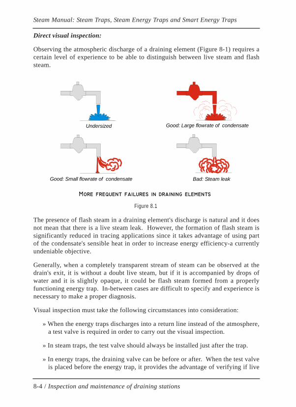
Direct visual inspection:
Observing the atmospheric discharge of a draining element (Figure 8-1) requires acertain level of experience to be able to distinguish between live steam and flashsteam.
The presence of flash steam in a draining element's discharge is natural and it doesnot mean that there is a live steam leak. However, the formation of flash steam issignificantly reduced in tracing applications since it takes advantage of using partof the condensate's sensible heat in order to increase energy efficiency-a currentlyundeniable objective.
Generally, when a completely transparent stream of steam can be observed at thedrain's exit, it is without a doubt live steam, but if it is accompanied by drops ofwater and it is slightly opaque, it could be flash steam formed from a properlyfunctioning energy trap. In-between cases are difficult to specify and experience isnecessary to make a proper diagnosis.
Visual inspection must take the following circumstances into consideration:
» When the energy traps discharges into a return line instead of the atmosphere,a test valve is required in order to carry out the visual inspection.
» In steam traps, the test valve should always be installed just after the trap.
» In energy traps, the draining valve can be before or after. When the test valveis placed before the energy trap, it provides the advantage of verifying if live
8-4 / Inspection and maintenance of draining stations
Steam Manual: Steam Traps, Steam Energy Traps and Smart Energy Traps
More frequent failures in draining elements
Good: Large flowrate of condensateUndersized
Good: Small flowrate of condensate Bad: Steam leak
Figure 8.1
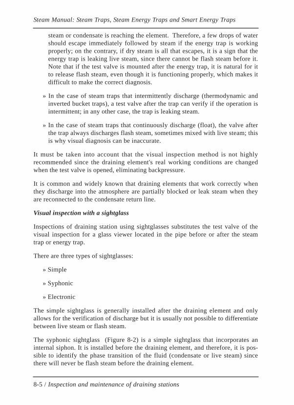
steam or condensate is reaching the element. Therefore, a few drops of watershould escape immediately followed by steam if the energy trap is workingproperly; on the contrary, if dry steam is all that escapes, it is a sign that theenergy trap is leaking live steam, since there cannot be flash steam before it.Note that if the test valve is mounted after the energy trap, it is natural for itto release flash steam, even though it is functioning properly, which makes itdifficult to make the correct diagnosis.
» In the case of steam traps that intermittently discharge (thermodynamic andinverted bucket traps), a test valve after the trap can verify if the operation isintermittent; in any other case, the trap is leaking steam.
» In the case of steam traps that continuously discharge (float), the valve afterthe trap always discharges flash steam, sometimes mixed with live steam; thisis why visual diagnosis can be inaccurate.
It must be taken into account that the visual inspection method is not highlyrecommended since the draining element's real working conditions are changedwhen the test valve is opened, eliminating backpressure.
It is common and widely known that draining elements that work correctly whenthey discharge into the atmosphere are partially blocked or leak steam when theyare reconnected to the condensate return line.
Visual inspection with a sightglass
Inspections of draining station using sightglasses substitutes the test valve of thevisual inspection for a glass viewer located in the pipe before or after the steamtrap or energy trap.
There are three types of sightglasses:
» Simple
» Syphonic
» Electronic
The simple sightglass is generally installed after the draining element and onlyallows for the verification of discharge but it is usually not possible to differentiatebetween live steam or flash steam.
The syphonic sightglass (Figure 8-2) is a simple sightglass that incorporates aninternal siphon. It is installed before the draining element, and therefore, it is pos-sible to identify the phase transition of the fluid (condensate or live steam) sincethere will never be flash steam before the draining element.
8-5 / Inspection and maintenance of draining stations
Steam Manual: Steam Traps, Steam Energy Traps and Smart Energy Traps
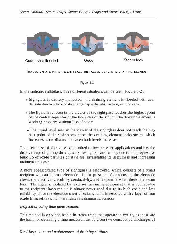
In the siphonic sightglass, three different situations can be seen (Figure 8-2):
» Sightglass is entirely inundated: the draining element is flooded with con-densate due to a lack of discharge capacity, obstruction, or blockage.
» The liquid level seen in the viewer of the sightglass reaches the highest pointof the central separator of the two sides of the siphon: the draining element isworking properly, without loss of steam.
» The liquid level seen in the viewer of the sightglass does not reach the hig-hest point of the siphon separator: the draining element leaks steam, whichincreases as the distance between both levels increases.
The usefulness of sightglasses is limited to low pressure applications and has thedisadvantage of getting dirty quickly, losing its transparency due to the progressivebuild up of oxide particles on its glass, invalidating its usefulness and increasingmaintenance costs.
A more sophisticated type of sightglass is electronic, which consists of a smallrecipient with an internal electrode. In the presence of condensate, the electrodecloses the electrical circuit by conductivity, and it opens it when there is a steamleak. The signal is isolated by exterior measuring equipment that is connectableto the recipient; however, its is almost never used due to its high costs and lowreliability, since the electrode short-circuits when it is recoated with a layer of ironoxide (magnetite) which invalidates its diagnostic purpose.
Inspection using time measurement
This method is only applicable in steam traps that operate in cycles, as these arethe basis for obtaining a time measurement between two consecutive discharges of
8-6 / Inspection and maintenance of draining stations
Steam Manual: Steam Traps, Steam Energy Traps and Smart Energy Traps
Codensate flooded Good
Images on a shyphon sightglass installed before a draining element
Figure 8.2

the trap. A chronometer is not necessary; it is sufficient to count 101, 102, 103, …in order to achieve a sufficiently valid duration of the trap cycles in seconds.
If there are no cycles, these three situations may occur:
» The trap is cold, out of service, or blocked.
» The trap is inundated with condensate and it discharges condensate at a lowtemperature, either as a result of under sizing or excessive backpressure.
» The trap leaks steam and has a very elevated temperature.
If the trap opens cyclically, verify that the duration of these cycles are not excessi-vely short. In thermodynamic disk traps, the duration of the cycles must not beless than 30 seconds; if not, the shorter the cycle is, the more deteriorated the inter-nal valve will be and the larger the energy loss will be.
Inspection using temperature
Inspecting draining elements exclusively using temperature measurements usuallyproduces errors, since it can only be applied correctly with additional informationthat is not typically available to the person performing the inspection. For thismethod of diagnosis to be reliable, the following facts must be understood:
» The type and operation of the draining element (continuous or intermittentdischarge, super-cooled or saturation temperature discharge), which determi-nes the discharge temperature adjustment limitations.
» The type of service (turbine protection, drip leg, process equipment, normaltracing, critical tracing, tank heating, …) determines the optimal dischargetemperature of the draining element for each application.
» Inlet pressure of the draining element: This value may vary due to the actionof regulator valves at entrances to equipment or because of variations in con-sumption. For example, in low-pressure steam networks, this value can fluc-tuate between 2.5 bar and 4 bar, altering the steam's saturation temperature.
» Outlet pressure of the draining element: this is usually unknown since it isnot enough to know the pressure in the steam line, but rather the amount ofpressure right at the energy trap's outlet, where there may be large variationsdue to the formation of local flash steam. Its value modifies the energy trap'sdischarge temperature.
The variations of outlet pressure can depend on multiple causes that are difficult toidentify (internal leaks, insufficient sizing of local return line, elevated dischargetemperature forming excessive flash steam, partial obstruction of the return line or
8-7 / Inspection and maintenance of draining stations
Steam Manual: Steam Traps, Steam Energy Traps and Smart Energy Traps
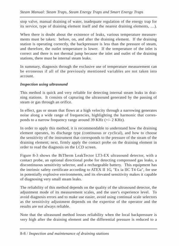
stop valve, manual draining of water, inadequate regulation of the energy trap forits service, type of draining element itself and the nearest draining elements, …).
When there is doubt about the existence of leaks, various temperature measure-ments must be taken: before, on, and after the draining element. If the drainingstation is operating correctly, the backpressure is less than the pressure of steam,and therefore, the outlet temperature is lower. If the temperature of the inlet iscorrect and there is not thermal jump because the inlet and outlet of the drainingstations, there must be internal steam leaks.
In summary, diagnosis through the exclusive use of temperature measurement canbe erroneous if all of the previously mentioned variables are not taken intoaccount.
Inspection using ultrasound
This method is quick and very reliable for detecting internal steam leaks in drai-ning stations. It consists of capturing the ultrasound generated by the passing ofsteam or gas through an orifice.
In effect, gas or steam that flows at a high velocity through a narrowing generatesnoise along a wide range of frequencies, highlighting the harmonic that corres-ponds to a narrow frequency range around 39 KHz (+/- 2 KHz).
In order to apply this method, it is recommendable to understand how the drainingelement operates, its discharge type (continuous or cyclical), and how to choosethe sensitivity of the instrument that corresponds to the pressure of the steam of thedraining element; next, firmly apply the contact probe on the draining element inorder to read the diagnosis on the LCD screen.
Figure 8-3 shows the BiTherm LeakTector LT3-EX ultrasound detector, with acontact probe, an optional directional probe for detecting compressed gas leaks, adiscontinuous sensitivity selector, and a rechargeable battery. This equipment hasthe intrinsic safety certificate according to ATEX II 1G, "Ex ia IIC T4 Ga", for usein potentially explosive environments, and its elevated sensitivity makes it capableof diagnosing very small steam leaks.
The reliability of this method depends on the quality of the ultrasound detector, theadjustment mode of its measurement scales, and the user's experience level. Toavoid diagnosis errors and to make use easier, avoid using continual scale selectorsas the sensitivity adjustment depends on the expertise of the operator and theresults are not always reliable.
Note that the ultrasound method losses reliability when the local backpressure isvery high after the draining element and the differential pressure is reduced to a
8-8 / Inspection and maintenance of draining stations
Steam Manual: Steam Traps, Steam Energy Traps and Smart Energy Traps
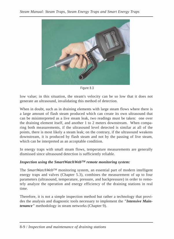
low value; in this situation, the steam's velocity can be so low that it does notgenerate an ultrasound, invalidating this method of detection.
When in doubt, such as in draining elements with large steam flows where there isa large amount of flash steam produced which can create its own ultrasound thatcan be misinterpreted as a live steam leak, two readings must be taken: one overthe draining element itself, and another 1 to 2 meters downstream. When compa-ring both measurements, if the ultrasound level detected is similar at all of thepoints, there is most likely a steam leak; on the contrary, if the ultrasound weakensdownstream, it is produced by flash steam and not by the passing of live steam,which can be interpreted as an acceptable condition.
In energy traps with small steam flows, temperature measurements are generallydismissed since ultrasound detection is sufficiently reliable.
Inspection using the SmartWatchWebTM remote monitoring system:
The SmartWatchWebTM monitoring system, an essential part of modern intelligentenergy traps and valves (Chapter 5.3), combines the measurement of up to fourparameters (ultrasound, temperature, pressure, and backpressure) in order to remo-tely analyze the operation and energy efficiency of the draining stations in realtime.
Therefore, it is not a simple inspection method but rather a technology that provi-des the analysis and diagnostic tools necessary to implement the "Intensive Main-tenance" methodology in steam networks (Chapter 9).
8-9 / Inspection and maintenance of draining stations
Steam Manual: Steam Traps, Steam Energy Traps and Smart Energy Traps
Figure 8.3

The measurements are automatically taken at regularly programmed intervals(usually every 5 seconds), saving all of the information gathered in a local orremote server, accessible to any authorized user.
The upper part of figure 8-4, shows a screen of the system's graphic interface; in it,the draining elements are grouped in loops. Each loop consists of 4 small coloredicons, all of which correspond to a monitored parameter (row 1-ultrasound, row 2-temperature, row 3-pressure, and row 4-backpressure). The color of each iconeasily identifies the status of the corresponding parameter.
Note that there is only a small number of icons that fall into rows 3 and 4 of theloops; this is because a lesser number of pressure and backpressure sensors isenough to obtain a pressure map of the steam/condensate network.
The measurements taken are kept in a history record, allowing for the analysis ofthe evolution of any incident in monitored draining elements as well as the verifi-cation of its correct interpretation; this way, the diagnosis obtained is highly relia-ble.
Clicking on any colored icon will provide the information that corresponds to thedraining element it represents, as shown in the lower section of figure 8-4.
This new screen of the graphic interface allows for the analysis of the evolution ofthe monitored parameters in the draining elements for any time range selected.
The combination of all of the information and the availability of measurementrecords makes it possible to have an accurate analysis, eliminating the diagnosticerrors described in all of the previously mentioned methods when evaluated indivi-dually. In effect, the variations detected in each parameter remain registered andtheir analysis allows for the identification of any incident; in addition, adequatelysetting the alarm thresholds, the system carries out a predictive analysis of inci-dents, making it possible to avoid failures and extend the life of the draining ele-ments considerably.
It is generally not required to check all of the individual information of each ele-ment being monitored unless it is necessary to do a full analysis. The interface hasa button that performs an instantaneous audit in all of the elements being monito-red and it generates a list of all of the incidents detected so that they may be repai-red immediately.
Lastly, there is an alarm screen that makes it possible to analyze any of themthroughout time in order to improve the facility's future operations.
8-10 / Inspection and maintenance of draining stations
Steam Manual: Steam Traps, Steam Energy Traps and Smart Energy Traps
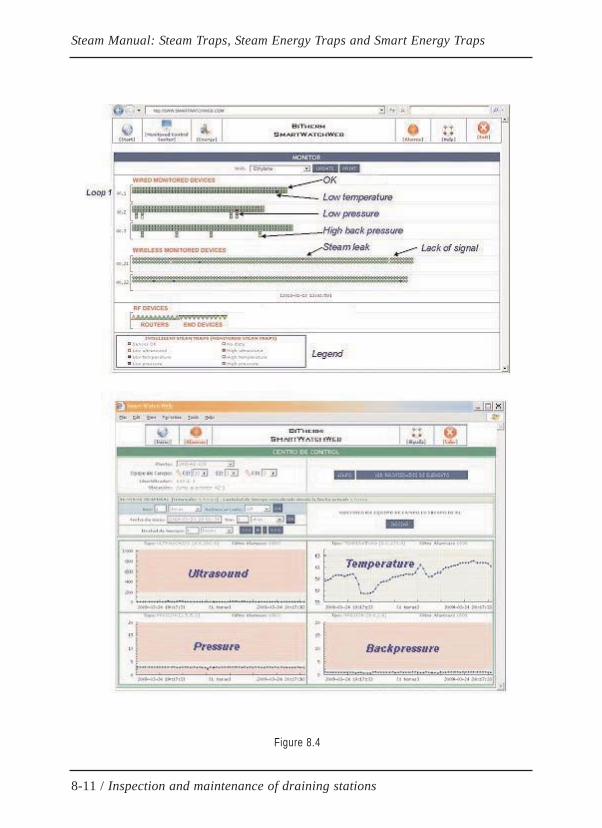
8-11 / Inspection and maintenance of draining stations
Steam Manual: Steam Traps, Steam Energy Traps and Smart Energy Traps
Figure 8.4
8.4 PURGE STATION INSPECTION PROTOCOLRecommended action protocol for performing purge station inspection is summari-zed below.
There are two cases:
Unmonitored purge stations
It is advisable to carry out a periodic inspection at least once every six months inorder to reduce energy and maintenance costs. The recommended inspection proce-dure is as follows:
1.Check the appearance of all the elements of the purge station (isolation val-ves, filter, steam trap, accessories, connections, identification tag of the purgestation, etc.) and take note any deficiencies observed in them.
2.Check and record the data of the steam trap (identification tag number, brand,model, size, connection type, steam inlet pressure, outlet pressure, type ofapplication, etc.).
3.Check the condition of the inlet and outlet isolation valves. If either of themis closed, the diagnosis is "out of service".
4.Check the status of the bypass valves (if any) and, if open, the diagnosis is"bypass purge"
5.Check that the purge element is not blocked; if its temperature is close to theenvironment and the purge station does not have a filter cleaning valve, thediagnosis is "blocked" or "flooded". If the purge station has a filter cleaningvalve, open it to blow the filter and check if it works out the problem. If thesituation persists, the diagnosis is "blocked" or "flooded".
6.If the purge station is operational, apply the contact probe of the ultrasonicdetector to the steam trap body to verify its operation. If the leak detectorshows high ultrasound it must be ensured that it is generated by the purgeelement and does not come from backgorund noice as structural vibrations,high level of flash steam, bypass leakage or from another near purge element.To do this, the probe of the detector must be applied in elements close to theone inspected to try to identify the source of ultrasound. In areas with pre-sence of structural vibrations you must reduce the sensitivity of the detectorand ensure that the ultrasound method is applicable; otherwise replace thismethod of verification with another. Once the validity of the method is gua-ranteed and assured that the ultrasound is caused by the purge element, seve-ral cases may occur:
8-12 / Inspection and maintenance of draining stations
Steam Manual: Steam Traps, Steam Energy Traps and Smart Energy Traps
» Continuous ultrasound < 20% of the scale. Diagnosis = "partial leak".
» Continuous ultrasound> 20% of the scale. Diagnosis = "continuous leak".
» Discontinuous ultrasound with cycle > 30 sg in thermodynamic vapor traps.Diagnosis = "Acceptable".
» Discontinuous ultrasound with cycle between 5 and 30 sg in thermodyna-mic steam traps. Diagnosis = "low performance".
» Discontinuous ultrasound with cycle <5 sg in thermodynamic steam traps.Diagnosis = "partial leak".
7.When the desired temperature is not reached in the process, it must be analy-zed if the purge station is well dimensioned and its adjustment is correct.
8.Finally record all the data collected in the field in an appropriate steam trapmanagement application, for example TrapHelp or SmartWatchWeb, in orderto easily obtain fault statistics, repair lists, energy losses due to failure, fai-lure types , distribution by types, etc.
9.Generate the final inspection report with recommendations to improve energyefficiency, reliability, operation and future maintenance of the installation.
Monitored purge stations (SmartWatchWeb)
In this case the inspection of the purge station is carried out continuously and auto-matically; however, it is recommended to carry out an ocular inspection on a regu-lar basis, for example every six months, to rule out possible incidents that cannotbe detected by the monitoring system itself (disassembly of sensors from their ori-ginal fixation, etc.).
It is important to note that all possible faults in purge stations will be detected andrecorded by the monitoring system provided that the thresholds of the monitoredparameters have been correctly adjusted (ultrasound, temperature, pressure andback pressure), otherwise the parameters will remain measured but the alarms willnot be real.
The correct setting of thresholds must be done by analyzing the application of eachpurge station to adapt them to each particular case in order to maximize its energyefficiency and optimize the operation of the installation.
The adjustment of monitored parameter thresholds should be set as indicatedbelow; however, these criteria will be modified according to the particular charac-teristics of each application and experience:
8-13 / Inspection and maintenance of draining stations
Steam Manual: Steam Traps, Steam Energy Traps and Smart Energy Traps

Ultrasound threshold:
In 8-bit resolution sensors (SWW-10 devices) the default basic threshold will beset to a digital value of 50. In case of structural noise the threshold will be set 50digital units above the average level of ultrasonic noise detected by the system. Inspecial cases, the threshold must be set according to the temperature threshold.
In 10-bit sensors (new SWW-11 devices) the default basic threshold will be set to adigital value of 200. In case of structural noise the threshold will be set to be set to200 digital units above the mean ultrasonic noise level detected by the system. Inspecial cases, the threshold must be set according to the temperature threshold.
Temperature threshold:
It must be set according to the application. However, if the temperature is measu-red outside the steam trap, it must be taken into account that the internal tempera-ture could be about 60 °C higher. In this case, the minimum temperature thresholdwill be the operating temperature minus 60 °C.
In the SWW-11 sensors, it is also possible to set a maximum temperature thres-hold; this maximum must be about 10 ° C. However, the difference between exter-nal and internal temperature in the steam trap must also be taken into account.Setting the maximum temperature threshold is important to lengthen the life of thesteam trap as it reduces the formation of flash steam in the trap, what means reduc-tion wear by erosion reducing maintenance costs.
In other applications, the same criteria will be used, adapting the thresholds to thesteam temperature in the process.
Pressure threshold:
The maximum inlet pressure threshold must be set at a high value, without excee-ding the maximum pressure that the purge element can withstand.
The minimum inlet pressure threshold must be set by default to a value 20% belowthe nominal steam pressure.
Back pressure threshold
The maximum outlet pressure threshold must be set according to the maximumpermissible backpressure value at each purge station, which depends on the exis-ting backpressure and type of steam trap. For example, in low pressure applica-tions (3.5 bar) this threshold will be 2.5 bar for thermostatic steam traps and 1.5bar for thermodynamic steam traps; in this way, a minimum differential pressurecompatible with the type of steam trap will be guaranteed to avoid operating pro-blems.
8-14 / Inspection and maintenance of draining stations
Steam Manual: Steam Traps, Steam Energy Traps and Smart Energy Traps

Obviously the minimum output pressure threshold is zero.
El umbral de presión de mínima de salida se debe habitualmente en cero.
8.5 MAINTENANCE OF PURGE STATIONSMaintenance of purge stations will depend on the inspection plan established bythe user; The longer the period between two consecutive inspections, the greaterthe deterioration of the purge elements and the greater the cost of spare parts.
In monitored purge stations, all anomalies are detected as soon as they appear andcan be repaired in less than 24 hours, this produces maximum benefits not only inenergy efficiency but in maintenance costs.
Thus, experience has shown that the purge elements multiply their useful life whenany detected incipient leak is repaired in less than 24 hours.
Repairs must always use original parts; avoiding repairing damaged parts unlessthey are subjected to the same thermal and surface treatments to which they weresubmitted by their manufacturer.
Whenever a vapor ramp is disassembled it is advisable to replace all existing gas-kets between joint surfaces to prevent further leakage.
In order to reduce repair costs and improve the operation of the installation, it isadvisable to use, whenever possible, balanced pressure bithermostatic traps andexternal adjustment mechanism. This considerably lengthens useful life and gre-atly reduces consumption of spare parts since their repairs are carried out by meansof a simple external adjustment, which is carried out without interruption of ser-vice and does not require any spare parts.
8-15 / Inspection and maintenance of draining stations
Steam Manual: Steam Traps, Steam Energy Traps and Smart Energy Traps

CHAPTER 9
ENERGY EFFICIENCY AND MAINTENANCE
9.1 INTRODUCTIONThe relationship that exists between the correct functioning of the draining ele-ments and energy efficiency of the steam network has already been mentioned inprevious chapters. However, there are some very common applications (tracing)where energy traps can act as a direct energy saving element, by simply adjustingits discharge temperature to 40 °C below the steam saturation temperature.
In other cases, it is possible to apply this concept although the discharge tempera-ture is adjusted closer to the values of the steam saturation temperature, such asdraining drip legs in distribution lines where there is a vertical distance from thedrip leg to the draining element greater than 2 meters; in this case it is possible toreduce the discharge temperature so that it is able to retain a small column of water(less than 1 m height) upstream of the steam trap, which reduces conductionenergy losses to the outside in the affected area due to the fact that the heat trans-mission coefficient of water-metal-air is a hundred times smaller than the heattransfer coefficient of steam-metal-air. Additionally, this practice extends the lifeof steam traps and reduces backpressure in the return line.
When discussing the topic of saving energy in steam networks, the energy effi-ciency of draining elements must be considered, which depends on its own energyconsumption as well as its direct and indirect energy losses associated with thetype of draining element.
Furthermore, any equipment requires maintenance in order to keep it functioningproperly, but in the case of equipment that handles energy, such as draining sta-tions, their maintenance must be focused on optimizing energy efficiency.
Until the birth of modern intelligent energy traps, the maintenance of draining sta-tions was corrective, with periodic survey campaigns being conducted, (yearly orbi annually) to detect incidents and steam leaks to be subsequently repaired.
9-1 / Energy efficiency and maintenance
Steam Manual: Steam Traps, Steam Energy Traps and Smart Energy Traps
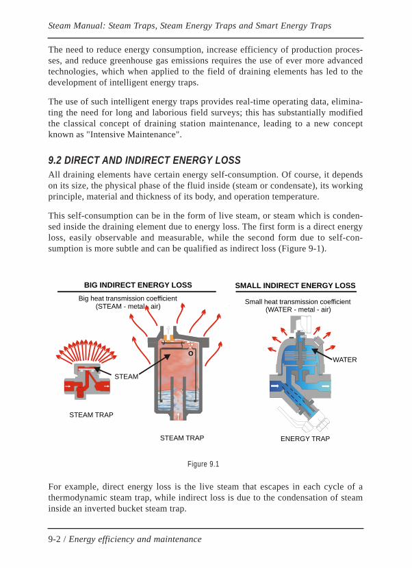
The need to reduce energy consumption, increase efficiency of production proces-ses, and reduce greenhouse gas emissions requires the use of ever more advancedtechnologies, which when applied to the field of draining elements has led to thedevelopment of intelligent energy traps.
The use of such intelligent energy traps provides real-time operating data, elimina-ting the need for long and laborious field surveys; this has substantially modifiedthe classical concept of draining station maintenance, leading to a new conceptknown as "Intensive Maintenance".
9.2 DIRECT AND INDIRECT ENERGY LOSSAll draining elements have certain energy self-consumption. Of course, it dependson its size, the physical phase of the fluid inside (steam or condensate), its workingprinciple, material and thickness of its body, and operation temperature.
This self-consumption can be in the form of live steam, or steam which is conden-sed inside the draining element due to energy loss. The first form is a direct energyloss, easily observable and measurable, while the second form due to self-con-sumption is more subtle and can be qualified as indirect loss (Figure 9-1).
For example, direct energy loss is the live steam that escapes in each cycle of athermodynamic steam trap, while indirect loss is due to the condensation of steaminside an inverted bucket steam trap.
9-2 / Energy efficiency and maintenance
Steam Manual: Steam Traps, Steam Energy Traps and Smart Energy Traps
STEAM
WATER
BIG INDIRECT ENERGY LOSS
STEAM TRAP ENERGY TRAP
Small heat transmission coefficient(WATER - metal - air)
SMALL INDIRECT ENERGY LOSSBig heat transmission coefficient
(STEAM - metal - air)
O
STEAM TRAP
Figure 9.1

In humid, cold or windy climates, the size of the trap has a significant influence onits self-consumption of energy. Of all atmospheric phenomena, rain is the mostinfluential on the energy losses of draining elements; they can be multiplied by 5to 10 times with respect to a dry day on thermodynamic steam traps (disk type).
Atmospheric phenomena strongly affect steam traps containing live steam inside,while they have a small influence on thermostatic energy traps which only containhot condensate. Obviously the condensation of steam inside the steam trap repre-sents an indirect energy loss that is much stronger than the energy loss due to sen-sible heat transfer on thermostatic traps that only contain hot condensate. Thishappens in float and inverted bucket traps where steam is always present; thissteam continuously condenses through heat transfer to the outside which constitu-tes an indirect loss of energy.
Indirect loss is particularly relevant in the thermodynamic disk trap whose uppercontrol chamber retains a small amount of steam, which aims to provide the clo-sing force; the heat transfer toward outside under the influence of the weather(rain, cold and wind) causes the condensation of steam retained in the controlchamber and the steam trap opens. This occurs even when there is no condensateto evacuate, discharging live steam into the return line.
To mitigate this energy loss, steam traps can be covered by a cap that protects themfrom the rain; remember that steam traps must never be thermally isolated in ordernot to hinder its automatic air venting ability.
Thermostatic energy traps are much less sensitive to indirect energy losses becausethere is only condensate inside and their efficiency is usually affected only around15%.
Another interesting aspect is the volume of the trap; the more voluminous it is, thegreater its indirect energy loss. Sizing of the internal valve must also be consideredbecause an oversized valve worsens its regulatory ability and causes more wearand tear, increasing energy and maintenance costs.
It is common to think that the losses of any small steam trap (1/2 ") are negligiblebecause they are generally used to drain a low flow rate, the order of 10 kg / h. Butthis is misleading, because individually a typical loss around 20 kg/h to 30 kg/h issmall in absolute value, but since the number of elements in this situation can riseto several hundred or thousands of elements the resulting amount is considerable.Note that the average flow rate of tracing points is around 10 Kg/h. Therefore, aloss of steam from 20 to 30 kg / h represents a huge energy waste from 200% to300%. Therefore, in practice, using intelligent energy traps is possible to save agigantic amount of energy on steam facilities where there are thousands of drai-ning elements (tracing and drip legs).
9-3 / Energy efficiency and maintenance
Steam Manual: Steam Traps, Steam Energy Traps and Smart Energy Traps

9.3 PRESURIZATION OF RETURN LINESPressurization of return lines has strong impact on the efficiency of the steam net-work. Return lines lead the condensate evacuated through draining elements andthe residual energy of the condensate to the boiler to be transformed back intosteam using part of the sensible heat of the liquid.
Internal steam leaks through draining elements produce a pressure increase inreturn lines, which causes serious problems affecting both the operation of thefacility as its energy efficiency.
The most important problems caused by pressurization of return lines are:
» Difficulty to return condensate to the boiler
» Reduction of discharge capacity of draining elements
» Modify the discharge temperature in thermostatic energy traps
» If backpressure exceeds 60% of the inlet pressure, it causes great loss ofenergy in thermodynamic traps.
» Increase the temperature in the return lines and thus energy losses by conduc-tion, convection and radiation into the atmosphere
» It favors cavitation in boiler feed pumps
» It causes thermal water hammers and thus the occurrence of leaks in valvesand fittings
» It reduces the overall energy efficiency of the steam network by recirculationof energy
Pressurization of the return lines is a spontaneous phenomenon associated with theflash steam formed in condensate discharge of draining traps (see section 1-3).
Pressurization of the return lines is the most common problem that is present inlarge facilities, such us refineries and chemical plants, where a huge amount ofdraining elements exists.
Pressurization of the return lines increases not only because of the presence ofinternal leaks of live steam but also because of the flash steam. The formation offlash steam depends on the condensate discharge temperature. It is obvious that theinfluence on the backpressure in the return lines depends on the type of drainingelement.
9-4 / Energy efficiency and maintenance
Steam Manual: Steam Traps, Steam Energy Traps and Smart Energy Traps
However, during the return lines design, sometimes the type of draining element isnot considered. This results in a bad calculation of the return lines backpressurewhich causes serious problems in the whole network, mainly when large steamnetwork are involved with low operating pressures (For example, tracing linesusing 3,5 bar steam pressure).
In accordance with section 6.5 in this manual, the theoretic amount of flash steamthat the return line will drive has to be considered to calculate the return line. Inthis calculation, it is required to consider a flow velocity of 15 m/s for the mentio-ned flash steam.
However, even in the situation that there is not any steam leak, the formation offlash steam does not only depend on the condensate discharge temperature but alsoon the small amounts of live steam put inside the return line. These small amountsare used as the control steam that some steam traps need to work properly (ther-modynamic steam traps, inverted bucket steam traps, impulse steam traps, etc).The mentioned small live steam injections allow certain amount of condensate torevaporize inside the return line, and this live steam is very difficult to estimate.
On the contrary, thermostatic energy traps reduce the return line backpressurebecause of their less discharge temperature. That means reduce the residual energydischarged to the return line.
In summary, theoretical calculations for sizing the return lines are valid when theycorrespond to draining elements discharging at the saturation point. Pressurizationwill be lower when using thermostatic energy traps, and will be higher to the theo-retical when using steam traps.
In the practice, frequently it happens that facilities are extended in the future butthe return line remains changeless. This, as well as the aged deterioration, worsensthe design situation to a situation where the network collapses. So, it is necessaryto discharge the condensate to the atmosphere, meaning huge energy losses.
One of the most harmful features of the pressurization of return lines is that itexpands quickly along the whole network, although the effect begins in lonelypoints, the discharge of steam traps affects other nearby. This results in increasingsteam leaks what means there is a multiplier effect that quickly expands along thewhole return line.
Thermostatic energy traps help to reduce this effect, due to the fact that the localbackpressure in the return line hinders and restricts the discharge of other nearbyenergy traps, avoiding that the effect quickly expands.
9-5 / Energy efficiency and maintenance
Steam Manual: Steam Traps, Steam Energy Traps and Smart Energy Traps
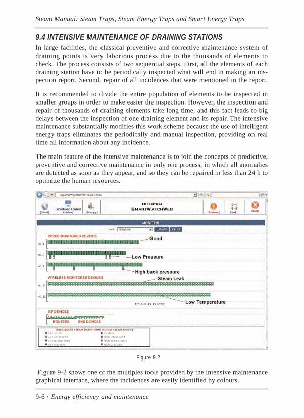
9.4 INTENSIVE MAINTENANCE OF DRAINING STATIONSIn large facilities, the classical preventive and corrective maintenance system ofdraining points is very laborious process due to the thousands of elements tocheck. The process consists of two sequential steps. First, all the elements of eachdraining station have to be periodically inspected what will end in making an ins-pection report. Second, repair of all incidences that were mentioned in the report.
It is recommended to divide the entire population of elements to be inspected insmaller groups in order to make easier the inspection. However, the inspection andrepair of thousands of draining elements take long time, and this fact leads to bigdelays between the inspection of one draining element and its repair. The intensivemaintenance substantially modifies this work scheme because the use of intelligentenergy traps eliminates the periodically and manual inspection, providing on realtime all information about any incidence.
The main feature of the intensive maintenance is to join the concepts of predictive,preventive and corrective maintenance in only one process, in which all anomaliesare detected as soon as they appear, and so they can be repaired in less than 24 h tooptimize the human resources.
Figure 9-2 shows one of the multiples tools provided by the intensive maintenancegraphical interface, where the incidences are easily identified by colours.
9-6 / Energy efficiency and maintenance
Steam Manual: Steam Traps, Steam Energy Traps and Smart Energy Traps
Figure 9.2
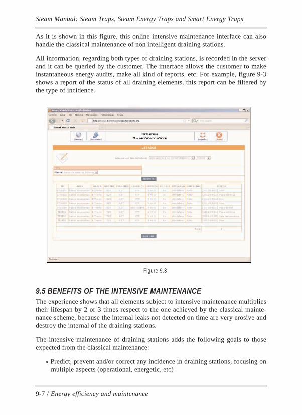
As it is shown in this figure, this online intensive maintenance interface can alsohandle the classical maintenance of non intelligent draining stations.
All information, regarding both types of draining stations, is recorded in the serverand it can be queried by the customer. The interface allows the customer to makeinstantaneous energy audits, make all kind of reports, etc. For example, figure 9-3shows a report of the status of all draining elements, this report can be filtered bythe type of incidence.
9.5 BENEFITS OF THE INTENSIVE MAINTENANCEThe experience shows that all elements subject to intensive maintenance multipliestheir lifespan by 2 or 3 times respect to the one achieved by the classical mainte-nance scheme, because the internal leaks not detected on time are very erosive anddestroy the internal of the draining stations.
The intensive maintenance of draining stations adds the following goals to thoseexpected from the classical maintenance:
» Predict, prevent and/or correct any incidence in draining stations, focusing onmultiple aspects (operational, energetic, etc)
9-7 / Energy efficiency and maintenance
Steam Manual: Steam Traps, Steam Energy Traps and Smart Energy Traps
Figure 9.3
» Reduce maintenance costs (they can be considered negligible because thebenefits of the intensive maintenance are much higher than that of total main-tenance costs)
» Increase reliability and availability of the steam and condensate network
» Increase safety of facilities and people
9.6 INTENSIVE MAINTENANCE AND ENERGY EFFICIENCYEnvironmental aspects and the efficient use of scarce resources, for example water,will impulse the energetic performances in the world during the next years. In theClimate Summit in Cancun, it was agreed that the global average temperature hasnot to exceed 2ºC in the year 2050, and to achieve this goal all required actions toreduce the greenhouse gas emissions have to be taken. The most outstanding actionthat can be taken is regarding energy efficiency because it contributes to reduceCO2 emissions and the consumption of products with high energy value in the mar-ket, as well as water that is a scarce resource in the world.
In the following years, all countries have to take actions to achieve this commit-ment especially since the 1st of January, 2012. This year, Kyoto Protocol finishes.The UE is leading environmental actions in the world. The UE has taken on thefirm commitment from all their Members to achieve a 20% improvement in energyefficiency and reduce 20% CO2 emissions in 2020 regarding those of 2008. Presu-mably, similar actions and even more strict will be agreed in coming Climate Sum-mits. The visible effects of the climate change (heavy flooding, large tornadoes,etc) will impulse new actions to reduce greenhouse gas emissions. Energy effi-ciency is the simplest and most profitable tool to achieve this goal, recognized bythe International Agency of Energy, followed by renewable energies, CO2 captureand storage, and Nuclear Energy.
Large energetic facilities should anticipate the coming changes, in an intelligentway, improving profitably the energy efficiency of those processes for reducingemissions. As it is known, Petrochemical facilities consume huge amount of steam,meaning energy, mainly generated from fossil fuels. Energy efficiency of steamnetworks is strongly conditioned by steam energy degradation, which is handledby thousands of draining elements, so considering all these elements as one onlyequipment, then becomes one of the most important steam consuming equipmentin these facilities. Additionally, steam leaks and energy inefficiency in drainingelements result in huge energy losses, increase of consumption of treated water,increase of production and maintenance costs, as well as huge CO2 emissions tothe atmosphere.
Currently, without any doubt, Intensive Maintenance applied in steam networks isthe tool that can have most impact for energy saving, to produce increases in
9-8 / Energy efficiency and maintenance
Steam Manual: Steam Traps, Steam Energy Traps and Smart Energy Traps
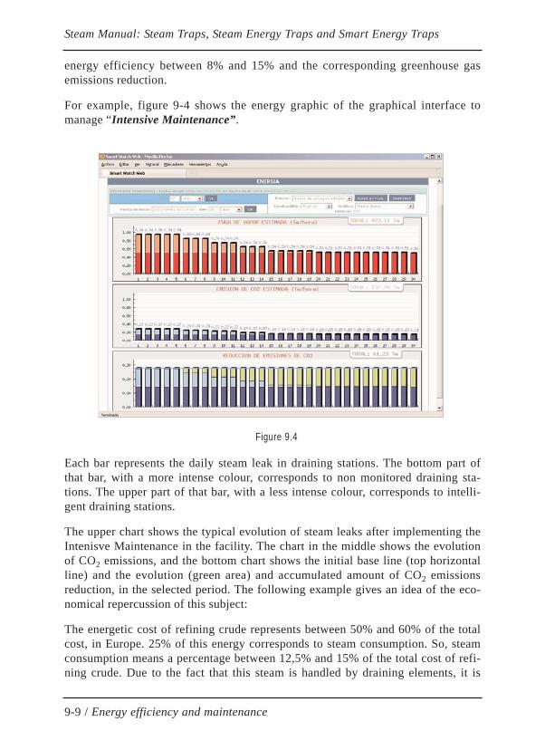
energy efficiency between 8% and 15% and the corresponding greenhouse gasemissions reduction.
For example, figure 9-4 shows the energy graphic of the graphical interface tomanage “Intensive Maintenance”.
Each bar represents the daily steam leak in draining stations. The bottom part ofthat bar, with a more intense colour, corresponds to non monitored draining sta-tions. The upper part of that bar, with a less intense colour, corresponds to intelli-gent draining stations.
The upper chart shows the typical evolution of steam leaks after implementing theIntenisve Maintenance in the facility. The chart in the middle shows the evolutionof CO2 emissions, and the bottom chart shows the initial base line (top horizontalline) and the evolution (green area) and accumulated amount of CO2 emissionsreduction, in the selected period. The following example gives an idea of the eco-nomical repercussion of this subject:
The energetic cost of refining crude represents between 50% and 60% of the totalcost, in Europe. 25% of this energy corresponds to steam consumption. So, steamconsumption means a percentage between 12,5% and 15% of the total cost of refi-ning crude. Due to the fact that this steam is handled by draining elements, it is
9-9 / Energy efficiency and maintenance
Steam Manual: Steam Traps, Steam Energy Traps and Smart Energy Traps
Figure 9.4
obvious that a 15% increase of its energy efficiency will reduce between 1,87%and 2,25% of the total refining cost (here it is not considered the additional benefitof reducing CO2 emissions).
Draining elements are the direct responsible for energy efficiency in the steamfacility as well as they are involved in the following aspects:
» Influence the increase of backpressure in return lines
» Influence in the occurrence of thermal water hammers
» Influence in the occurrence of thermal water hammers
» Affect the lifespan of the facility: pipelines, accessories, …
» Control the energetic degradation of steam and, so, influence in the genera-tion of CO2 emissions
» Contribute to the general thought about the right use of energy
The following information highlights the importance of this matter:
One steam leak (42 Kg/h) in a small draining element (1/2” size) installed in a lowpressure steam line, represents an energy cost of 368 tons of steam per year and103 Tons of CO2 emissions to the atmosphere per year.
In order to estimate steam leaks occurring in draining elements, it can be used thesoftware "Simulation of steam leaks" in the following website:
http://www.smartwatchweb.com
9.7 ADVICES ABOUT REPAIRING OF DRAINING STATIONSIt is worth to recall that all repairs have to be done by using the original spare partsfrom the supplier, in all cases, avoiding repair the damaged pieces unless they arethermally treated, and coated as they were originally.
It is advisable to replace all gaskets between the bonding surfaces after disassem-bling a draining element in order to avoid future steam leaks.
It is advisable to use bithermostatic energy traps, whenever possible, which is abalanced pressure energy trap and with external adjustment mechanism in order toreduce repair costs and improve operation in the facility. Using this type of energytrap considerably lengthens lifespan and highly reduces the use of spare parts, asits repairs can be done by only using the external adjustment without interruptingsteam in the facility.
9-10 / Energy efficiency and maintenance
Steam Manual: Steam Traps, Steam Energy Traps and Smart Energy Traps
