"portable tow winch"snocamp.s3.amazonaws.com/.../files/tow_winch_(1).docx · web viewthis...
TRANSCRIPT

Draft – Student Work
Portable Tow Winch
Advanced Technical Drawing
Alex B
9/30/13

Draft – Student Work
Project Description Project Brief
To create a portable tow winch for a variety of board sports in order to allow them to be used in a greater variety of places.
Rationale Neither wakeboards nor snowboards move by themselves. Snowboards require a
hill, and wakeboards require a boat to pull it. However, sometimes they aren’t available. This winch allows wakeboarding and snowboarding almost anywhere, especially where that hill doesn’t exist or the boat can’t fit. This winch will now allow me and my friends to explore more areas that were previously unavailable.
Learning Goals I have wanted to learn how to weld for a while, and this would allow me to learn and
practice, because the whole frame is metal tubing. Also, this will allow me to improve at snowboarding and wakeboarding.
Research Materials
The bulk of the project will be constructed of steel. 1¼” and 2” angle steel will be used for the frame. Angle steel is cheaper that steel tubing, but is sufficiently strong for this project. None of the pieces are high-stress parts, so the strength tube steel provides is not absolutely necessary. The base rectangle will be 2”, because it will need to be stronger. I don’t want it flexing, because the rest of the winch is dependent on it. Also, if I add a hitch mount later, the strength will be key, because the whole winch will end up weighing 75lbs or so.
HOME DEPOT
Steel $75.281 2" x 2" x 72" angle steel1 2" x 2" x 36" angle steel1 1 1/4" x 1 1/4" x 72" angle steel2 1 1/4" x 1 1/4" x 36" angle steel

Draft – Student Work
Approximately 2’ of 1” steel tubing for the handle and tire spacers. This isn’t necessary, but it become very nice for moving around. I found this lying around the shop, so it was free. It would probably only be $5 to buy,
though.
Metal panels will be cut to form the outside skin of the frame. This will protect the motor and spool, as well as keeping the whole thing more contained and compact. It will also form a splash-guard. A friend had extras, so this was of no cost. Maybe $40 or so to buy, because there is a
fair amount of it.
The frame and exterior will be painted with Rust-Oleum, or a comparable product to increase the life of the steel. This also doubles aesthetically, looking better than just grey metal.
A 212cc engine will provide the power for the winch. It will produce 6.5 hp and 8.5 lbs of torque. A torque converter will be used in place of a centrifugal clutch. This will provide a smoother pull and more power.
HARBOR FREIGHT
6.5HP Predator Engine $116.18
Go Cart parts will be used for the spool. A 1inch axle will provide the basis, with go cart hubs used to hold the spool and gear. The axle will sit in pillow blocks.
HOME DEPOT
Axle Hardware $10.222 3/4" x 6" hex bolts2 3/4" washers2 3/4" bolts
Winch hardware $15.6512 3/8" x 1" hex bolts12 3/8" lock washers8 3/8" lock nuts16 3/8" reg nuts4 3/8" x 1.5" hex bolts1 3/8" x 24" threaded rod

Draft – Student Work
BMI KARTS
Spool parts #1 $80.031/4" x 12" key stock#40 chain 70 link (not long enough)54T sprocket w/ Aluminum hub6" split rim2 aluminum hubs (ended up being wrong bolt pattern)
Spool parts #2 $62.335' #40 chain + 2 master links2 4x4 aluminum hubs
EBAY
2 Warming pans $11.242 1" pillow blocks $19.82
METAL DEPOT
Axle $39.572 24" x 1" steel round (bought two in case I screwed up, but only used one)1 24" x 3/4" steel rod (didn’t use)
Ideally, 400’ of 7/64” Dymeea cord will be used. It has one of the greatest strength-to-weight ratios of any rope. It’s so light, it even floats. It has minimal stretch, so the rider won’t feel like he or she is bouncing back and forth while they are being pulled. Similar materials are used in regular wakeboard tow ropes. And while this isn’t as important, it comes in red and blue, which looks awesome. But it costs about $100, so it will wait. For now, I will use a wakeboard towrope I have, plus an additional section of climbing
rope. This totals around 200’, and will function fine in the meantime.
To translate the power from the engine to the spool will be a TAV 2 torque converter (and a chain obviously). These are used on go-karts to provide a more gradual pull, while increasing torque. They mount easily to the engine. A standard #40 go-kart chain will also be used.
EBAY
Comet TAV2 torque converter $109.99

Draft – Student Work
Two old tractor tires were used as wheels. These are a must, because it becomes impractical to carry when fully built because of the weight. Same friend had these, though I’ve seen them for only like $5 apiece
Winch fairlead will act as a cable guide.
EBAY
ATV Roller fair lead $16.73
All in all, the total is $481.76. This was right on budget for me, as I was hoping to spend less than $500. Granted, I was able to get some parts for free. The other side is that I wasn’t as careful as I could have been with orders, and I ended up buying more than I needed at times. I probably could have knocked $50 if I were to build another one.
Tools Used A wire-feed welder is used for welding the framing. And other various metal parts Metal drop band saw will be used for cutting the steel. Stationary grinder, metal grinder, and dremel will be used for grinding various parts. Heavy duty corded drill for drilling holes on for the engine and the pillow blocks. Lathe for creating spacers on wheels and the axle Sheet metal roller for spool and splash guard Mill for cutting keyway Other basic measuring tools, such as calipers were necessary as pieces needed to be fairly
accurate
Process Used Welding may be used heavily throughout the project. The entire frame will have to be
welded together piece by piece Lathing was used to mill down the wheel spacers and the axle Milling was used to cut a keyway in the axle for the spool
6S Integration S 1-5
Not applicable Safety

Draft – Student Work
By attaching the metal panels on the outside, this prevents people from getting too close to the parts. While not inherently dangerous, touching any of the spinning parts could lead to injury. But the frame prevents this.
Terms and Information “tacking”
Small welds used to hold the metal together before making longer welds
Tips and Practice “Measure twice, Cut once.” As annoying as it might be, it still holds truth. Especially with
people like me who tend to rush, slowing down and paying more attention to details will result in a better product.
Safety glasses will also be a good idea throughout the build. The type of steel makes a difference. Rolled steel is stronger than bent steel. It is slightly
more expensive, but worth it. The problem is it looks similar from a distance. However, the rolled angle steel has a sharp outer edge, where the bent steel is rounded.
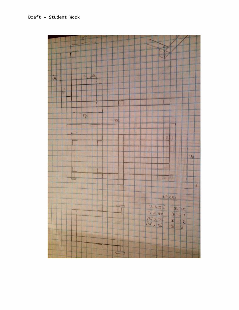
Design Documentation Sketches
I had a rough idea of what I wanted the frame to look like, because id looked at examples online. I wanted a simple L shape, with a platform inside for the spool to sit on. This seemed to be the simplest, as well as strongest. It had to be adapted, because most online plans used steel tube, but I decided I wanted to used angle steel because of the cost. The first three sketches show the evolution of this.

Draft – Student Work
The top is a design I had seen online. While it required the least material, its complexity seemed like it would be too much. I kept the forward-angled support on the next draft, but
added vertical supports.

Draft – Student Work
This was the next draft, maintaining the through hitch and angled supports. However, I moved the spool to mount back to the angled support, allowing vertical and horizontal
adjustment, similar to the original. I also flipped the orientation of the angled base.

Draft – Student Work
I dropped the angle supports for a simpler to build design. This still allowed adjustable spool position, but is much easier to build. And at this point, I was able to start adding dimensions.

Draft – Student Work
CAD Sketches/Rendering Once I had decided on the frame shape, I drew it in Solid Works. This allowed me to import
other parts to check the frame size, confirming everything would fit. I didn’t need to, but I could have also analyzed its properties to determine if the welds would hold in certain situations. For example, if I had added a hitch mount, I would have gone through the process to make sure it would be strong enough.
I took the sketch and drew it in Solid Works. I was able to see in more detail what it would look like, and make sure the rest of the parts would fit.

Draft – Student Work
After finalizing a design, I was able to work with the lengths to allow the most efficient use of material. Of almost 20’ of steel, I used all but like a foot of it.
Process Steps Gathering Materials
Once I figured out what I wanted to do, the first step was to get what I needed to do so. I started with the steel, because the bulk of the building was the frame. Essentially the rest was bolting stuff on. This way I could start working while I save up for the rest of the pieces. I bought the pieces in section over a month or two.
I was hoping to use tube steel, but the only place that had it was almost an hour away. I went with the angle steel instead, because Home Depot had it in stock. I modified the dimensions of the frame slightly so that I only had to buy about 110” of each (one 72” and one 36” piece). I ended up needing a second shorter piece of 1¼” steel because I was unable to get the steel for the hitch mount.
Prep Work After I had all of the steel, I had to cut it down to size. The Metal band saw made short
work of this. However, this was after a couple days of adjusting it, sense it hadn’t been
Draft – Student Work
used in a while. It still had a tendency to pull in, so the cuts were slightly angled, but they could be ground back with relative ease. In addition, we had to rethread a stripped part and replace the broken handle. After it was all completed, the actual cutting only took about a half an hour.
Next came the welding. This was tricky at first. I started with some practice welds, sense I had never welded before. The first day was awful. But after adjusting the settings correctly, it slowly got better. Tacking the pieces together wasn’t hard, but getting even welds was very difficult. I started with tacking the base together, and then moved on to the winch support. I purposely didn’t do the engine mount, because I wanted to wait until the motor arrived. It took a week to finish the welds, but they turned out alright.
After cutting the pieces, I was able to lay them out before welding.

Draft – Student Work
Base welded
At this point, I decided to flip the orientation of the base, so that the flat side would rest on the ground. I don’t know why this didn’t dawn on me earlier, because it wouldn’t have made sense to do it the other way around.
Front two upright supports

Draft – Student Work
I would later add a metal bar between the top of these to increase lateral strength and form a handle for carrying. It also made attaching the splash guard easier.
Frame (mostly) assembled. There definitely was a learning curve that came with welding, but towards the end, I was happy with the welds. I had to go back and touch up a couple, though. I
purposely left the motor mount out for until it had actually arrived. I wasn’t completely sure how it would sit, so I left it alone and moved on. The blue shows a support I would add later.
Next was to attach the wheels. I welded ¾” bolts on each side straight to the frame, and then welded angled pieces inside to increase the strength. I had to also make a spacer so that the wheel hub wouldn’t crash into the frame. To do so, I welded two big washers onto a section of pipe. I then lathed down one of them, so that the spacer wouldn’t hit the front section of the base.

Draft – Student Work
Wheel space (blue) and brace (red)
Frame and wheels assembled

Draft – Student Work
Welding the spacers. In shorts…
After the frame was together, the next step was to start the spool. First, I needed an axle. I had to mill it down about .01” to allow the hubs to slide on easier. After that, I had to mill out a keyway so that the hubs would stay in place. This was much easier than I had suspected. I had ordered two in case I messed one up, but it came out almost perfect the first time.
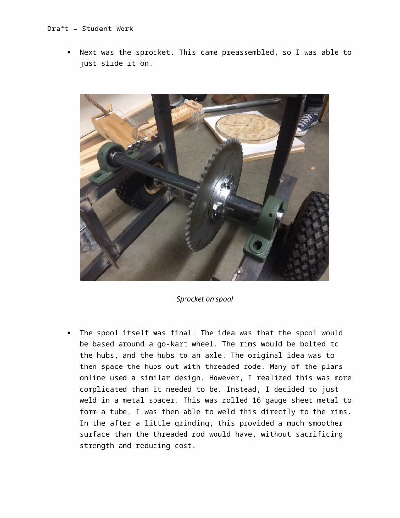
Next was the sprocket. This came preassembled, so I was able to just slide it on.

Draft – Student Work
Sprocket on spool
The spool itself was final. The idea was that the spool would be based around a go-kart wheel. The rims would be bolted to the hubs, and the hubs to an axle. The original idea was to then space the hubs out with threaded rode. Many of the plans online used a similar design. However, I realized this was more complicated than it needed to be. Instead, I decided to just weld in a metal spacer. This was rolled 16 gauge sheet metal to form a tube. I was then able to weld this directly to the rims. In the after a little grinding, this provided a much smoother surface than the threaded rod would have, without sacrificing strength and reducing cost.

Draft – Student Work
Spool before and after. The left without the center; the right with. The grinded circle on bot hubs was to create better contact when welding.
After this, I was able to assemble everything. All this required was sliding the sections on the axle, and resting them in the pillow blocks. And the pillow blocks bolted straight to the frame.
After the spool was complete and the motor had arrived, I was able to go back and finish the motor mount. I had already cut the sections, so all that involved was welding them in place. From there, I was able to drill out holes and bolt the engine on.
Engine finally bolted on

Draft – Student Work
I had forgotten another part. I needed to mount the spool guide. I had drilled out holes so that the supports would be facing out, but I realized that that would limit the cord going back on the spool. I flipped the pieces and had to re-drill the holes. Once I had them drilled the right way, I went to fit them to the frame, but the front edge of the supports hung too far off the frame, so I had to go back and grind out notches on the back so it would fit better.
The guide installed. The blue arrow shows where I had to grind down a notch.
VS
The blue shows how it was originally orientated. But that limited the cord winding the spool, so by flipping it to the current orientation, it opened more space, as seen in black.

Draft – Student Work
The torque converter arrived soon after, so I was able to install that. However, it didn’t include instructions, so it took some fiddling with to properly set up. After that was on, the chain was able to go on too. The slots on the pillow blocks allowed me to slide it back just far enough to get the chain on the sprocket. Of course, the first section of chain I had was too short, and the second was too long. So I took the longer section, and marked out how many links I would need. Then I had to use the dremel to grind down the pin to where I could push it out with a nail. After that, a connector pin slid in and connected the two sections. But it stuck out a ways, so I also had to grind it down a little.
As I began moving the winch around the shop, I realized how heavy and awkward it was to move. It needed a handle on the back to help with wheeling and lifting. The simplest way was to mill out two slots on the back to act as handholds. This wouldn’t have worked, because the motors position would have made them hard to grab, and they would have been uncomfortable. In the end, I built a handle out of pipe. I cut two 6” sections and one 16” of 1” pipe on the band saw. I took the 6” sections and cut semicircles out of one side of both. The long section of pipe would sit in the whole. On the other end, I milled the pipe at an angle so that it would stick off the back of the winch at a comfortable angle. After having all the pieces, I welded all of them together. It ended up being very strong and comfortable. I would have liked it to have been about 3” longer, but I wound out that when I put it in my car, I could only close the trunk with about 1” of clearance as it was, so an extension wouldn’t have worked.
The handle, after it had been cut and welded. The red shows the rough outline of the pipe, after it had been milled.

Draft – Student Work
With everything assembled, it was finally done! Well, at least it was functional. I wound up a temporary cord, and it was ready to go. There was plenty more I wanted to do, but I could at least start testing it at this point.
Draft – Student Work
Reflection and Analysiso Function of Project
I was very surprised how well this ended up working. This was after overcoming some engine trouble at first. I didn’t put enough oil in, so the engine’s low oil safety feature kicked in unknowingly and wouldn’t turn over. We figured that out, but it still wouldn’t start. We then found that the clutch on/off was backwards of what we though, so it was flooding. But after 30min of messing around, we finally got it to fire up
We started by pulling a person on a skateboard, which at only 75% was too fast to be safe. Pulling someone on a bike was about the same. Next, we tried skis on damp grass. I was unsure if it would work, but it also pulled my younger brother fine. This escalated into snowboards, sleds, and even a kayak, all of which it handled without trouble.
The real test was with a wakeboard. It took some careful positioning and a creative tie-down, but we were eventually able to get it secure. We motored out in a small inflatable dingy, and started sitting on the edge of the dingy with the board resting on the water; a dock start in wakeboard jargon. The winch was fired up, and it instantly provided enough torque to pull and keep all 175 lbs of me up! It was not as fast as a boat, but still plenty fast for what I was hoping! We were running into issues with the winch, so we didn’t try a start with the rider in the water, but I’m pretty sure that would work as well.
The final test will be with a snowboard, but wakeboarding has to overcome much more friction, so I’m not worried about it failing. It will be harder to secure down, but that is the only problem I can foresee.
o Aesthetic Design Honestly, I wasn’t paying much attention to the aesthetics, and more on
function. I have seen some online that look really good, but most of those were much more expensive and/or require tools that I didn’t have available. For example, one professional model had metal decals cut out of the sheet metal siding. While looking good, this would have taken a significant amount of time; more than I was willing to invest. But after painting the frame and adding decals, the overall aesthetics will improve.
o Craftsmanship and Finish There was three significant craftsmanship issues throughout the winch;
metal warping, poor welds, and rushed measurement.

Draft – Student Work
I had expected a little warping, but the frame was warped more than expected by the time I had finished. It’s in steels nature to warp. To prevent this, I should have used magnetic braces to keep angles square, and spaced out the welds to distribute heat evenly. However, I did neither of these. We didn’t have the magnetic squares, so I didn’t have much of a choice there. But I did rush the welding, and had a habit of doing one area at a time. These both contributed to the warping. Luckily, the warping didn’t affect performance, but it did detract from the aesthetic appeal.
The poor weld were a result of no prior experience and rushing. I hadn’t welded at all before, so I learned as I went. I had to touch up some of the original welds, but I could tell I was getting much better as time went on.
Upon careful inspection, you will find multiple appealingly random holes. There are two on the motor mount, one on the spool, and two near the spool guide. These were all because of rushing measurements, which ended up being inaccurate. I should have paid more attention to “measure twice, cut once.” Luckily, none significantly effected performance, but they also detract from the aesthetic appeal.
Learning and Growth I had two goals going into this project, improve my shop skills, and
improve my boarding skills. It’s too early to comment about the second, but my shop skills drastically increased. I was exposed to many tools I had never used, more than just welding as I had expected. The only large tool I didn’t use was the CNC mill, but I will use that in later projects. Other than that, I either learned new skill or improved skills I already had on a multitude of tools.
Plans for Improvement Corrections
At high speeds for extended times, the spool begins to slide to the left. This throws off the chain alignment, and the chain crashes into the wall of the torque converter. I will eventually remove the axle and tap two small holes on each end so that the allen screws on the pillow blocks would sit in. this way it wouldn’t rely simply on friction to hold the axle.

Draft – Student Work
During wakeboarding, the welds holding the spacer onto the rims failed. We were able to fix that with ducktape, but that is not a permanent fix. I would like to go back and re-weld that, as well as probably adding an additional section to increase the strength.
There were a couple spots like on the handle where I realized I missed a weld. So the frame will take one more going over to make sure everything is set.
Additions Spool walls are a must. I have the pieces to do so, I just didn’t get to
adding them yet. During testing, the cord got pulled over twice and tangled in between the rim and the sprocket. It didn’t cause damage, but it was annoying to fix. And they would allow more cord to be added to the spool
A Rustoleum coating will also be necessary. Even after one day, surface rust was already appearing. Rustoleum won’t entirely prevent rust, but it will drastically increase the frames lifespan.
A final addition will be a remote throttle. I’m not entirely sure of the design yet, but the goal is so that the operator can run the winch from a standing position, so he isn’t forced to be squatting right next to the throttle level on the engine. This obviously isn’t necessary, but it would be convenient to have
Final thoughts Despite minor flaws, I am very impressed with the completed project.
Performance was much better than expected, cost was right on budget, and I learned and improved my shop skills dramatically. Overall, I am completely satisfied.