polycom realpresence dma 7000 system...
TRANSCRIPT
6.3 | June 2015 | 3725-76302-001QOperations Guide
Polycom® RealPresence® DMA® 7000 System
The Polycom RealPresence DMA 7000 System is also known and certified as the DMA System.
2
Copyright© 2015, Polycom, Inc. All rights reserved. No part of this document may be reproduced, translated into another language or format, or transmitted in any form or by any means, electronic or mechanical, for any purpose, without the express written permission of Polycom, Inc.
6001 America Center DriveSan Jose, CA 95002USA
Polycom®, the Polycom logo and the names and marks associated with Polycom products are trademarks and/or service marks of Polycom, Inc. and are registered and/or common law marks in the United States and various other countries. All other trademarks are property of their respective owners. No portion hereof may be reproduced or transmitted in any form or by any means, for any purpose other than the recipient's personal use, without the express written permission of Polycom.
End User License Agreement By installing, copying, or otherwise using this product, you acknowledge that you have read, understand and agree to be bound by the terms and conditions of the End User License Agreement for this product. The EULA for this product is available on the Polycom Support page for the product.
Patent Information The accompanying product may be protected by one or more U.S. and foreign patents and/or pending patent applications held by Polycom, Inc.
Open Source Software Used in this Product This product may contain open source software. You may receive the open source software from Polycom up to three (3) years after the distribution date of the applicable product or software at a charge not greater than the cost to Polycom of shipping or distributing the software to you.
Disclaimer While Polycom uses reasonable efforts to include accurate and up-to-date information in this document, Polycom makes no warranties or representations as to its accuracy. Polycom assumes no liability or responsibility for any typographical or other errors or omissions in the content of this document.
Limitation of Liability Polycom and/or its respective suppliers make no representations about the suitability of the information contained in this document for any purpose. Information is provided "as is" without warranty of any kind and is subject to change without notice. The entire risk arising out of its use remains with the recipient. In no event shall Polycom and/or its respective suppliers be liable for any direct, consequential, incidental, special, punitive or other damages whatsoever (including without limitation, damages for loss of business profits, business interruption, or loss of business information), even if Polycom has been advised of the possibility of such damages.
Customer Feedback We are striving to improve our documentation quality and we appreciate your feedback. Email your opinions and comments to [email protected].
Polycom Support Visit the Polycom Support Center for End User License Agreements, software downloads, product documents, product licenses, troubleshooting tips, service requests, and more.
Polycom, Inc. 3
Contents
Polycom® RealPresence DMA® 7000 System Overview . . . . . . . . . . . . . . . . . . . 14Introduction to the Polycom RealPresence DMA System . . . . . . . . . . . . . . . . . . . . . . . . . . . . 14
The Polycom RealPresence DMA System’s Primary Functions . . . . . . . . . . . . . . . . . . . . 14
The Polycom RealPresence DMA System’s Three Configurations . . . . . . . . . . . . . . . . . 17
System Capabilities and Constraints . . . . . . . . . . . . . . . . . . . . . . . . . . . . . . . . . . . . . . . . 19
System Port Usage . . . . . . . . . . . . . . . . . . . . . . . . . . . . . . . . . . . . . . . . . . . . . . . . . . . . . . 19
Polycom Solution Support . . . . . . . . . . . . . . . . . . . . . . . . . . . . . . . . . . . . . . . . . . . . . . . . . . . . 21
Working in the Polycom RealPresence DMA System . . . . . . . . . . . . . . . . . . . . . . . . . . . . . . . 22
Accessing the Polycom RealPresence DMA System . . . . . . . . . . . . . . . . . . . . . . . . . . . . 22
Field Input Requirements . . . . . . . . . . . . . . . . . . . . . . . . . . . . . . . . . . . . . . . . . . . . . . . . . 22
Settings Dialog . . . . . . . . . . . . . . . . . . . . . . . . . . . . . . . . . . . . . . . . . . . . . . . . . . . . . . . . . 23
Polycom RealPresence DMA System User Roles and Their Access Privileges . . . . . . . . 23
Open Source Software . . . . . . . . . . . . . . . . . . . . . . . . . . . . . . . . . . . . . . . . . . . . . . . . . . . . . . 26
License Information . . . . . . . . . . . . . . . . . . . . . . . . . . . . . . . . . . . . . . . . . . . . . . . . . . . . . . 26
Polycom RealPresence DMA System Initial Configuration Summary . . . . . . . . 28Add Required DNS Records for the Polycom RealPresence DMA System . . . . . . . . . . . . . . 29
Additional DNS Records for SIP Proxy . . . . . . . . . . . . . . . . . . . . . . . . . . . . . . . . . . . . . . . 29
Additional DNS Records for the H.323 Gatekeeper . . . . . . . . . . . . . . . . . . . . . . . . . . . . . 30
Additional DNS Records for the Optional Embedded DNS Feature . . . . . . . . . . . . . . . . . 30
Verify That DNS Is Working for All Addresses . . . . . . . . . . . . . . . . . . . . . . . . . . . . . . . . . 31
License the Polycom RealPresence DMA System . . . . . . . . . . . . . . . . . . . . . . . . . . . . . . . . . 31
License the RealPresence DMA System, Appliance Edition . . . . . . . . . . . . . . . . . . . . . . 31
License the RealPresence DMA System, Virtual Edition . . . . . . . . . . . . . . . . . . . . . . . . . 32
Set Up Signaling . . . . . . . . . . . . . . . . . . . . . . . . . . . . . . . . . . . . . . . . . . . . . . . . . . . . . . . . . . . 32
Configure the Call Server and Optionally Create a Supercluster . . . . . . . . . . . . . . . . . . . . . . 33
Set Up Security . . . . . . . . . . . . . . . . . . . . . . . . . . . . . . . . . . . . . . . . . . . . . . . . . . . . . . . . . . . . 33
Set Up MCUs . . . . . . . . . . . . . . . . . . . . . . . . . . . . . . . . . . . . . . . . . . . . . . . . . . . . . . . . . . . . . . 34
Connect to Microsoft Active Directory® . . . . . . . . . . . . . . . . . . . . . . . . . . . . . . . . . . . . . . . . . . 35
Set Up Conference Templates . . . . . . . . . . . . . . . . . . . . . . . . . . . . . . . . . . . . . . . . . . . . . . . . 36
Test the System . . . . . . . . . . . . . . . . . . . . . . . . . . . . . . . . . . . . . . . . . . . . . . . . . . . . . . . . . . . . 37
Contents
Polycom, Inc. 4
System Security . . . . . . . . . . . . . . . . . . . . . . . . . . . . . . . . . . . . . . . . . . . . . . . . . . . 38Security Certificates Overview . . . . . . . . . . . . . . . . . . . . . . . . . . . . . . . . . . . . . . . . . . . . . . . . . 38
How Certificates Work . . . . . . . . . . . . . . . . . . . . . . . . . . . . . . . . . . . . . . . . . . . . . . . . . . . . 38
Forms of Certificates Accepted by the Polycom RealPresence DMA System . . . . . . . . . 38
How Certificates Are Used by the Polycom RealPresence DMA System . . . . . . . . . . . . . 39
Frequently Asked Questions . . . . . . . . . . . . . . . . . . . . . . . . . . . . . . . . . . . . . . . . . . . . . . . 41
Certificate Settings . . . . . . . . . . . . . . . . . . . . . . . . . . . . . . . . . . . . . . . . . . . . . . . . . . . . . . . . . 42
Certificate Information Dialog . . . . . . . . . . . . . . . . . . . . . . . . . . . . . . . . . . . . . . . . . . . . . . 43
Certificate Signing Request Dialog . . . . . . . . . . . . . . . . . . . . . . . . . . . . . . . . . . . . . . . . . 44
Add Certificates Dialog . . . . . . . . . . . . . . . . . . . . . . . . . . . . . . . . . . . . . . . . . . . . . . . . . . . 44
Certificate Details Dialog . . . . . . . . . . . . . . . . . . . . . . . . . . . . . . . . . . . . . . . . . . . . . . . . . 45
Certificate Procedures . . . . . . . . . . . . . . . . . . . . . . . . . . . . . . . . . . . . . . . . . . . . . . . . . . . . . . 46
Install a Certificate Authority’s Certificate . . . . . . . . . . . . . . . . . . . . . . . . . . . . . . . . . . . . . 46
Create a Certificate Signing Request . . . . . . . . . . . . . . . . . . . . . . . . . . . . . . . . . . . . . . . . 47
Install a Certificate in the RealPresence DMA System . . . . . . . . . . . . . . . . . . . . . . . . . . 49
Remove a Certificate from the RealPresence DMA System . . . . . . . . . . . . . . . . . . . . . . 50
Security Settings . . . . . . . . . . . . . . . . . . . . . . . . . . . . . . . . . . . . . . . . . . . . . . . . . . . . . . . . . . . 52
The Consequences of Enabling Maximum Security Mode . . . . . . . . . . . . . . . . . . . . . . . . . . . 56
Enabling File Uploads in Maximum Security with Mozilla Firefox . . . . . . . . . . . . . . . . . . . 58
Login Policy Settings . . . . . . . . . . . . . . . . . . . . . . . . . . . . . . . . . . . . . . . . . . . . . . . . . . . . . . . 59
Local Password . . . . . . . . . . . . . . . . . . . . . . . . . . . . . . . . . . . . . . . . . . . . . . . . . . . . . . . . 59
Session . . . . . . . . . . . . . . . . . . . . . . . . . . . . . . . . . . . . . . . . . . . . . . . . . . . . . . . . . . . . . . 60
Local User Account . . . . . . . . . . . . . . . . . . . . . . . . . . . . . . . . . . . . . . . . . . . . . . . . . . . . . 61
Banner . . . . . . . . . . . . . . . . . . . . . . . . . . . . . . . . . . . . . . . . . . . . . . . . . . . . . . . . . . . . . . . 61
Access Policy Settings . . . . . . . . . . . . . . . . . . . . . . . . . . . . . . . . . . . . . . . . . . . . . . . . . . . 62
Reset System Passwords . . . . . . . . . . . . . . . . . . . . . . . . . . . . . . . . . . . . . . . . . . . . . . . . . . . . 63
Local Cluster Configuration . . . . . . . . . . . . . . . . . . . . . . . . . . . . . . . . . . . . . . . . . . 64Network Settings . . . . . . . . . . . . . . . . . . . . . . . . . . . . . . . . . . . . . . . . . . . . . . . . . . . . . . . . . . . 64
Routing Configuration Dialog . . . . . . . . . . . . . . . . . . . . . . . . . . . . . . . . . . . . . . . . . . . . . . 70
Time Settings . . . . . . . . . . . . . . . . . . . . . . . . . . . . . . . . . . . . . . . . . . . . . . . . . . . . . . . . . . . . . . 70
Licenses . . . . . . . . . . . . . . . . . . . . . . . . . . . . . . . . . . . . . . . . . . . . . . . . . . . . . . . . . . . . . . . . . 71
Licenses for the Appliance Edition . . . . . . . . . . . . . . . . . . . . . . . . . . . . . . . . . . . . . . . . . . 71
Licenses for the Virtual Edition . . . . . . . . . . . . . . . . . . . . . . . . . . . . . . . . . . . . . . . . . . . . . 72
Add Licenses . . . . . . . . . . . . . . . . . . . . . . . . . . . . . . . . . . . . . . . . . . . . . . . . . . . . . . . . . . . 73
Signaling Settings . . . . . . . . . . . . . . . . . . . . . . . . . . . . . . . . . . . . . . . . . . . . . . . . . . . . . . . . . . 75
H.323, SIP, and WebRTC Signaling . . . . . . . . . . . . . . . . . . . . . . . . . . . . . . . . . . . . . . . . . 75
Add Guest Port Dialog . . . . . . . . . . . . . . . . . . . . . . . . . . . . . . . . . . . . . . . . . . . . . . . . . . . 80
Edit Guest Port Dialog . . . . . . . . . . . . . . . . . . . . . . . . . . . . . . . . . . . . . . . . . . . . . . . . . . . . 81
Add Guest Prefix Dialog . . . . . . . . . . . . . . . . . . . . . . . . . . . . . . . . . . . . . . . . . . . . . . . . . . 82
Contents
Polycom, Inc. 5
Edit Guest Prefix Dialog . . . . . . . . . . . . . . . . . . . . . . . . . . . . . . . . . . . . . . . . . . . . . . . . . . 83
Configure Signaling . . . . . . . . . . . . . . . . . . . . . . . . . . . . . . . . . . . . . . . . . . . . . . . . . . . . . . 83
Configure Logging Settings . . . . . . . . . . . . . . . . . . . . . . . . . . . . . . . . . . . . . . . . . . . . . . . . . . . 85
Alerting Settings . . . . . . . . . . . . . . . . . . . . . . . . . . . . . . . . . . . . . . . . . . . . . . . . . . . . . . . . . . . 87
Configure Remote Backup Settings . . . . . . . . . . . . . . . . . . . . . . . . . . . . . . . . . . . . . . . . . . . . 87
Automatically Send Usage Data . . . . . . . . . . . . . . . . . . . . . . . . . . . . . . . . . . . . . . . . . . . . . . . 89
Enable or Disable Automatic Data Collection . . . . . . . . . . . . . . . . . . . . . . . . . . . . . . . . . . 90
See the Collected Usage Data . . . . . . . . . . . . . . . . . . . . . . . . . . . . . . . . . . . . . . . . . . . . . 90
Device Management . . . . . . . . . . . . . . . . . . . . . . . . . . . . . . . . . . . . . . . . . . . . . . . . 91Active Calls . . . . . . . . . . . . . . . . . . . . . . . . . . . . . . . . . . . . . . . . . . . . . . . . . . . . . . . . . . . . . . . 91
Call Details Dialog . . . . . . . . . . . . . . . . . . . . . . . . . . . . . . . . . . . . . . . . . . . . . . . . . . . . . . . 92
Endpoints . . . . . . . . . . . . . . . . . . . . . . . . . . . . . . . . . . . . . . . . . . . . . . . . . . . . . . . . . . . . . . . . . 95
Names/Aliases in a Mixed H.323 and SIP Environment . . . . . . . . . . . . . . . . . . . . . . . . . . 98
Naming ITP Systems Properly for Recognition by the Polycom RealPresence DMA System 99
Add Endpoint Dialog . . . . . . . . . . . . . . . . . . . . . . . . . . . . . . . . . . . . . . . . . . . . . . . . . . . . 100
Edit Device Dialog . . . . . . . . . . . . . . . . . . . . . . . . . . . . . . . . . . . . . . . . . . . . . . . . . . . . . . 101
Edit Devices Dialog . . . . . . . . . . . . . . . . . . . . . . . . . . . . . . . . . . . . . . . . . . . . . . . . . . . . . 102
Add Alias Dialog . . . . . . . . . . . . . . . . . . . . . . . . . . . . . . . . . . . . . . . . . . . . . . . . . . . . . . . 103
Edit Alias Dialog . . . . . . . . . . . . . . . . . . . . . . . . . . . . . . . . . . . . . . . . . . . . . . . . . . . . . . . 103
Associate User Dialog . . . . . . . . . . . . . . . . . . . . . . . . . . . . . . . . . . . . . . . . . . . . . . . . . . . 103
Site Statistics . . . . . . . . . . . . . . . . . . . . . . . . . . . . . . . . . . . . . . . . . . . . . . . . . . . . . . . . . . . . . 103
Site Link Statistics . . . . . . . . . . . . . . . . . . . . . . . . . . . . . . . . . . . . . . . . . . . . . . . . . . . . . . . . . 104
External Gatekeeper . . . . . . . . . . . . . . . . . . . . . . . . . . . . . . . . . . . . . . . . . . . . . . . . . . . . . . . 105
Add External Gatekeeper Dialog . . . . . . . . . . . . . . . . . . . . . . . . . . . . . . . . . . . . . . . . . . . 106
Edit External Gatekeeper Dialog . . . . . . . . . . . . . . . . . . . . . . . . . . . . . . . . . . . . . . . . . . . 107
External SIP Peer . . . . . . . . . . . . . . . . . . . . . . . . . . . . . . . . . . . . . . . . . . . . . . . . . . . . . . . . . 109
Multiple External SIP Peers . . . . . . . . . . . . . . . . . . . . . . . . . . . . . . . . . . . . . . . . . . . . . . 109
Add External SIP Peer Dialog . . . . . . . . . . . . . . . . . . . . . . . . . . . . . . . . . . . . . . . . . . . . . 110
Edit External SIP Peer Dialog . . . . . . . . . . . . . . . . . . . . . . . . . . . . . . . . . . . . . . . . . . . . . 115
SIP Peer Postliminary Output Format Options . . . . . . . . . . . . . . . . . . . . . . . . . . . . . . . . 120
Add Authentication Dialog . . . . . . . . . . . . . . . . . . . . . . . . . . . . . . . . . . . . . . . . . . . . . . . . 124
Edit Authentication Dialog . . . . . . . . . . . . . . . . . . . . . . . . . . . . . . . . . . . . . . . . . . . . . . . . 124
Add Outbound Registration Dialog . . . . . . . . . . . . . . . . . . . . . . . . . . . . . . . . . . . . . . . . . 125
Edit Outbound Registration Dialog . . . . . . . . . . . . . . . . . . . . . . . . . . . . . . . . . . . . . . . . . 126
External H.323 SBC . . . . . . . . . . . . . . . . . . . . . . . . . . . . . . . . . . . . . . . . . . . . . . . . . . . . . . . 127
Add External H.323 SBC Dialog . . . . . . . . . . . . . . . . . . . . . . . . . . . . . . . . . . . . . . . . . . . 128
Edit External H.323 SBC Dialog . . . . . . . . . . . . . . . . . . . . . . . . . . . . . . . . . . . . . . . . . . . 129
Contents
Polycom, Inc. 6
MCU Management . . . . . . . . . . . . . . . . . . . . . . . . . . . . . . . . . . . . . . . . . . . . . . . . . 131MCUs . . . . . . . . . . . . . . . . . . . . . . . . . . . . . . . . . . . . . . . . . . . . . . . . . . . . . . . . . . . . . . . . . . . 131
Considerations when using MCUs with the RealPresence DMA system . . . . . . . . . . . . 133
Add an MCU . . . . . . . . . . . . . . . . . . . . . . . . . . . . . . . . . . . . . . . . . . . . . . . . . . . . . . . . . . 136
Edit an MCU . . . . . . . . . . . . . . . . . . . . . . . . . . . . . . . . . . . . . . . . . . . . . . . . . . . . . . . . . . 141
Add a Session Profile . . . . . . . . . . . . . . . . . . . . . . . . . . . . . . . . . . . . . . . . . . . . . . . . . . . 146
Edit a Session Profile . . . . . . . . . . . . . . . . . . . . . . . . . . . . . . . . . . . . . . . . . . . . . . . . . . . 146
Delete an MCU . . . . . . . . . . . . . . . . . . . . . . . . . . . . . . . . . . . . . . . . . . . . . . . . . . . . . . . . 147
Stop Using an MCU . . . . . . . . . . . . . . . . . . . . . . . . . . . . . . . . . . . . . . . . . . . . . . . . . . . . 147
Busy Out an MCU . . . . . . . . . . . . . . . . . . . . . . . . . . . . . . . . . . . . . . . . . . . . . . . . . . . . . . 148
Start Using an MCU Again . . . . . . . . . . . . . . . . . . . . . . . . . . . . . . . . . . . . . . . . . . . . . . . 148
ISDN Gateway Selection Process . . . . . . . . . . . . . . . . . . . . . . . . . . . . . . . . . . . . . . . . . . 148
MCU Pools . . . . . . . . . . . . . . . . . . . . . . . . . . . . . . . . . . . . . . . . . . . . . . . . . . . . . . . . . . . . . . 149
Add an MCU Pool . . . . . . . . . . . . . . . . . . . . . . . . . . . . . . . . . . . . . . . . . . . . . . . . . . . . . 150
Edit an MCU Pool . . . . . . . . . . . . . . . . . . . . . . . . . . . . . . . . . . . . . . . . . . . . . . . . . . . . . . 151
Delete an MCU Pool . . . . . . . . . . . . . . . . . . . . . . . . . . . . . . . . . . . . . . . . . . . . . . . . . . . . 151
MCU Pool Orders . . . . . . . . . . . . . . . . . . . . . . . . . . . . . . . . . . . . . . . . . . . . . . . . . . . . . . . . . 152
Add an MCU Pool Order . . . . . . . . . . . . . . . . . . . . . . . . . . . . . . . . . . . . . . . . . . . . . . . . . 153
Edit an MCU Pool Order . . . . . . . . . . . . . . . . . . . . . . . . . . . . . . . . . . . . . . . . . . . . . . . . . 154
Delete an MCU Pool Order . . . . . . . . . . . . . . . . . . . . . . . . . . . . . . . . . . . . . . . . . . . . . . . 154
MCU Selection Process . . . . . . . . . . . . . . . . . . . . . . . . . . . . . . . . . . . . . . . . . . . . . . . . . 155
MCU Availability and Reliability Tracking . . . . . . . . . . . . . . . . . . . . . . . . . . . . . . . . . . . . 156
Integrations with Other Systems . . . . . . . . . . . . . . . . . . . . . . . . . . . . . . . . . . . . . 158Microsoft Active Directory® Integration . . . . . . . . . . . . . . . . . . . . . . . . . . . . . . . . . . . . . . . . . 158
Microsoft Active Directory Page . . . . . . . . . . . . . . . . . . . . . . . . . . . . . . . . . . . . . . . . . . . 159
Active Directory Cache Refresh Frequency . . . . . . . . . . . . . . . . . . . . . . . . . . . . . . . . . . 164
Active Directory Integration Procedure . . . . . . . . . . . . . . . . . . . . . . . . . . . . . . . . . . . . . . 165
Understanding Base DN . . . . . . . . . . . . . . . . . . . . . . . . . . . . . . . . . . . . . . . . . . . . . . . . . 168
Add Passcodes for Enterprise Users . . . . . . . . . . . . . . . . . . . . . . . . . . . . . . . . . . . . . . . 170
About the System’s Directory Queries . . . . . . . . . . . . . . . . . . . . . . . . . . . . . . . . . . . . . . 171
Microsoft® Lync® 2013 Integration . . . . . . . . . . . . . . . . . . . . . . . . . . . . . . . . . . . . . . . . . . . . . 174
Lync 2010 vs. Lync 2013 Integration . . . . . . . . . . . . . . . . . . . . . . . . . . . . . . . . . . . . . . . 175
Scheduled Conferences with Polycom RealConnect™ . . . . . . . . . . . . . . . . . . . . . . . . . 175
Automatic Contact Creation and Configuration . . . . . . . . . . . . . . . . . . . . . . . . . . . . . . . . 176
Active Directory Service Account Permissions . . . . . . . . . . . . . . . . . . . . . . . . . . . . . . . . 176
Lync and non-Lync Endpoint Collaboration . . . . . . . . . . . . . . . . . . . . . . . . . . . . . . . . . . 177
Considerations and Requirements for Lync 2013 Integration . . . . . . . . . . . . . . . . . . . . . 177
Lync 2010 and 2013 Client / Server Feature Support . . . . . . . . . . . . . . . . . . . . . . . . . . . 178
Integrate RealPresence DMA and Lync 2013 . . . . . . . . . . . . . . . . . . . . . . . . . . . . . . . . . 179
Contents
Polycom, Inc. 7
Diagnose Presence Problems . . . . . . . . . . . . . . . . . . . . . . . . . . . . . . . . . . . . . . . . . . . . . 179
Microsoft Exchange Server Integration . . . . . . . . . . . . . . . . . . . . . . . . . . . . . . . . . . . . . . . . . 179
Polycom Solution and Integration Support . . . . . . . . . . . . . . . . . . . . . . . . . . . . . . . . . . . 180
Differences between Calendaring and Scheduling . . . . . . . . . . . . . . . . . . . . . . . . . . . . . 180
Microsoft Exchange Server Page . . . . . . . . . . . . . . . . . . . . . . . . . . . . . . . . . . . . . . . . . . 181
Exchange Server Integration Procedure . . . . . . . . . . . . . . . . . . . . . . . . . . . . . . . . . . . . . 181
RealPresence Resource Manager Integration . . . . . . . . . . . . . . . . . . . . . . . . . . . . . . . . . . . 183
RealPresence Resource Manager Page . . . . . . . . . . . . . . . . . . . . . . . . . . . . . . . . . . . . . 184
RealPresence Resource Manager Integration Procedures . . . . . . . . . . . . . . . . . . . . . . . 185
Juniper Networks SRC Integration . . . . . . . . . . . . . . . . . . . . . . . . . . . . . . . . . . . . . . . . . . . . 186
Juniper Networks SRC Page . . . . . . . . . . . . . . . . . . . . . . . . . . . . . . . . . . . . . . . . . . . . . 186
Juniper Networks SRC Integration Procedure . . . . . . . . . . . . . . . . . . . . . . . . . . . . . . . . 187
Conference Manager Configuration . . . . . . . . . . . . . . . . . . . . . . . . . . . . . . . . . . 188Conference Settings . . . . . . . . . . . . . . . . . . . . . . . . . . . . . . . . . . . . . . . . . . . . . . . . . . . . . . . 188
Class of Service . . . . . . . . . . . . . . . . . . . . . . . . . . . . . . . . . . . . . . . . . . . . . . . . . . . . . . . 191
Default Polycom Conference Contacts Presence Settings . . . . . . . . . . . . . . . . . . . . . . . 191
Remove Contacts from Active Directory Dialog . . . . . . . . . . . . . . . . . . . . . . . . . . . . . . . 192
Conference Templates . . . . . . . . . . . . . . . . . . . . . . . . . . . . . . . . . . . . . . . . . . . . . . . . . . . . . 193
Two Types of Templates . . . . . . . . . . . . . . . . . . . . . . . . . . . . . . . . . . . . . . . . . . . . . . . . . 193
Template Priority . . . . . . . . . . . . . . . . . . . . . . . . . . . . . . . . . . . . . . . . . . . . . . . . . . . . . . . 195
About Conference IVR Services . . . . . . . . . . . . . . . . . . . . . . . . . . . . . . . . . . . . . . . . . . . 195
About Cascading . . . . . . . . . . . . . . . . . . . . . . . . . . . . . . . . . . . . . . . . . . . . . . . . . . . . . . . 196
WebRTC Conference Feature Limitations . . . . . . . . . . . . . . . . . . . . . . . . . . . . . . . . . . . 199
Conference Templates List . . . . . . . . . . . . . . . . . . . . . . . . . . . . . . . . . . . . . . . . . . . . . . . 199
Add Conference Template Dialog . . . . . . . . . . . . . . . . . . . . . . . . . . . . . . . . . . . . . . . . . . 200
Edit Conference Template Dialog . . . . . . . . . . . . . . . . . . . . . . . . . . . . . . . . . . . . . . . . . . 211
Select Layout Dialog . . . . . . . . . . . . . . . . . . . . . . . . . . . . . . . . . . . . . . . . . . . . . . . . . . . . 222
Conference Templates Procedures . . . . . . . . . . . . . . . . . . . . . . . . . . . . . . . . . . . . . . . . 222
External Lync Systems . . . . . . . . . . . . . . . . . . . . . . . . . . . . . . . . . . . . . . . . . . . . . . . . . . . . . 224
Add an External Lync System . . . . . . . . . . . . . . . . . . . . . . . . . . . . . . . . . . . . . . . . . . . . . 225
Edit an External Lync System . . . . . . . . . . . . . . . . . . . . . . . . . . . . . . . . . . . . . . . . . . . . . 227
IVR Prompt Sets . . . . . . . . . . . . . . . . . . . . . . . . . . . . . . . . . . . . . . . . . . . . . . . . . . . . . . . . . . 228
Shared Number Dialing . . . . . . . . . . . . . . . . . . . . . . . . . . . . . . . . . . . . . . . . . . . . . . . . . . . . . 230
Add Virtual Entry Queue Dialog . . . . . . . . . . . . . . . . . . . . . . . . . . . . . . . . . . . . . . . . . . . 233
Add Direct Dial Virtual Entry Queue Dialog . . . . . . . . . . . . . . . . . . . . . . . . . . . . . . . . . . . 234
Edit Virtual Entry Queue Dialog . . . . . . . . . . . . . . . . . . . . . . . . . . . . . . . . . . . . . . . . . . . 235
Edit Direct Dial Virtual Entry Queue Dialog . . . . . . . . . . . . . . . . . . . . . . . . . . . . . . . . . . . 237
Script Debugging Dialog for VEQ Scripts . . . . . . . . . . . . . . . . . . . . . . . . . . . . . . . . . . . . 237
Sample Virtual Entry Queue Script . . . . . . . . . . . . . . . . . . . . . . . . . . . . . . . . . . . . . . . . . 238
Contents
Polycom, Inc. 8
Superclustering . . . . . . . . . . . . . . . . . . . . . . . . . . . . . . . . . . . . . . . . . . . . . . . . . . . 240About Superclustering . . . . . . . . . . . . . . . . . . . . . . . . . . . . . . . . . . . . . . . . . . . . . . . . . . . . . . 240
DMAs . . . . . . . . . . . . . . . . . . . . . . . . . . . . . . . . . . . . . . . . . . . . . . . . . . . . . . . . . . . . . . . . . . . 241
Join Supercluster Dialog . . . . . . . . . . . . . . . . . . . . . . . . . . . . . . . . . . . . . . . . . . . . . . . . . 244
Supercluster Procedures . . . . . . . . . . . . . . . . . . . . . . . . . . . . . . . . . . . . . . . . . . . . . . . . . . . . 245
Call Server Configuration . . . . . . . . . . . . . . . . . . . . . . . . . . . . . . . . . . . . . . . . . . . 247About the Call Server Capabilities . . . . . . . . . . . . . . . . . . . . . . . . . . . . . . . . . . . . . . . . . . . . . 247
Call Server Settings . . . . . . . . . . . . . . . . . . . . . . . . . . . . . . . . . . . . . . . . . . . . . . . . . . . . . . . . 248
Domains . . . . . . . . . . . . . . . . . . . . . . . . . . . . . . . . . . . . . . . . . . . . . . . . . . . . . . . . . . . . . . . . 252
Dial Rules . . . . . . . . . . . . . . . . . . . . . . . . . . . . . . . . . . . . . . . . . . . . . . . . . . . . . . . . . . . . . . . 254
Test Dial Rules Dialog . . . . . . . . . . . . . . . . . . . . . . . . . . . . . . . . . . . . . . . . . . . . . . . . . . . 255
The Default Dial Plan and Suggestions for Modifications . . . . . . . . . . . . . . . . . . . . . . . . 257
Add Dial Rule Dialog . . . . . . . . . . . . . . . . . . . . . . . . . . . . . . . . . . . . . . . . . . . . . . . . . . . . 260
Edit Dial Rule Dialog . . . . . . . . . . . . . . . . . . . . . . . . . . . . . . . . . . . . . . . . . . . . . . . . . . . . 265
Preliminary/Postliminary Scripting . . . . . . . . . . . . . . . . . . . . . . . . . . . . . . . . . . . . . . . . . . . . . 269
Predefined Preliminary/Postliminary Scripting Variables . . . . . . . . . . . . . . . . . . . . . . . . 269
Preliminary/Postliminary Scripting Functions . . . . . . . . . . . . . . . . . . . . . . . . . . . . . . . . . 270
How Dial Rule Actions Affect SIP Headers . . . . . . . . . . . . . . . . . . . . . . . . . . . . . . . . . . . 272
Script Debugging Dialog for Preliminaries/Postliminaries . . . . . . . . . . . . . . . . . . . . . . . . 273
Sample Preliminary and Postliminary Scripts . . . . . . . . . . . . . . . . . . . . . . . . . . . . . . . . . 274
Hunt Groups . . . . . . . . . . . . . . . . . . . . . . . . . . . . . . . . . . . . . . . . . . . . . . . . . . . . . . . . . . . . . 281
Add Hunt Group Dialog . . . . . . . . . . . . . . . . . . . . . . . . . . . . . . . . . . . . . . . . . . . . . . . . . . 282
Edit Hunt Group Dialog . . . . . . . . . . . . . . . . . . . . . . . . . . . . . . . . . . . . . . . . . . . . . . . . . . 282
Add Alias Dialog . . . . . . . . . . . . . . . . . . . . . . . . . . . . . . . . . . . . . . . . . . . . . . . . . . . . . . . 283
Edit Alias Dialog . . . . . . . . . . . . . . . . . . . . . . . . . . . . . . . . . . . . . . . . . . . . . . . . . . . . . . . 283
Device Authentication . . . . . . . . . . . . . . . . . . . . . . . . . . . . . . . . . . . . . . . . . . . . . . . . . . . . . . 283
Add Device Authentication Dialog . . . . . . . . . . . . . . . . . . . . . . . . . . . . . . . . . . . . . . . . . . 285
Edit Device Authentication Dialog . . . . . . . . . . . . . . . . . . . . . . . . . . . . . . . . . . . . . . . . . . 286
Registration Policy . . . . . . . . . . . . . . . . . . . . . . . . . . . . . . . . . . . . . . . . . . . . . . . . . . . . . . . . . 286
Registration Policy Scripting . . . . . . . . . . . . . . . . . . . . . . . . . . . . . . . . . . . . . . . . . . . . . . 288
Script Debugging Dialog for Registration Policy Scripts . . . . . . . . . . . . . . . . . . . . . . . . . 290
Sample Registration Policy Scripts . . . . . . . . . . . . . . . . . . . . . . . . . . . . . . . . . . . . . . . . . 291
Prefix Service . . . . . . . . . . . . . . . . . . . . . . . . . . . . . . . . . . . . . . . . . . . . . . . . . . . . . . . . . . . . 296
Add Simplified ISDN Gateway Dialing Prefix Dialog . . . . . . . . . . . . . . . . . . . . . . . . . . . . 297
Edit Simplified ISDN Gateway Dialing Prefix Dialog . . . . . . . . . . . . . . . . . . . . . . . . . . . . 298
Edit Vertical Service Code Dialog . . . . . . . . . . . . . . . . . . . . . . . . . . . . . . . . . . . . . . . . . . 299
Embedded DNS . . . . . . . . . . . . . . . . . . . . . . . . . . . . . . . . . . . . . . . . . . . . . . . . . . . . . . . . . . . 299
History Retention Settings . . . . . . . . . . . . . . . . . . . . . . . . . . . . . . . . . . . . . . . . . . . . . . . . . . . 301
Contents
Polycom, Inc. 9
Site Topology . . . . . . . . . . . . . . . . . . . . . . . . . . . . . . . . . . . . . . . . . . . . . . . . . . . . 303About Site Topology . . . . . . . . . . . . . . . . . . . . . . . . . . . . . . . . . . . . . . . . . . . . . . . . . . . . . . . 303
Bandwidth Management . . . . . . . . . . . . . . . . . . . . . . . . . . . . . . . . . . . . . . . . . . . . . . . . . 304
Sites . . . . . . . . . . . . . . . . . . . . . . . . . . . . . . . . . . . . . . . . . . . . . . . . . . . . . . . . . . . . . . . . . . . . 305
Site Information Dialog . . . . . . . . . . . . . . . . . . . . . . . . . . . . . . . . . . . . . . . . . . . . . . . . . . 306
Add Site Dialog . . . . . . . . . . . . . . . . . . . . . . . . . . . . . . . . . . . . . . . . . . . . . . . . . . . . . . . . 307
Edit Site Dialog . . . . . . . . . . . . . . . . . . . . . . . . . . . . . . . . . . . . . . . . . . . . . . . . . . . . . . . . 311
Add Subnet Dialog . . . . . . . . . . . . . . . . . . . . . . . . . . . . . . . . . . . . . . . . . . . . . . . . . . . . . 315
Edit Subnet Dialog . . . . . . . . . . . . . . . . . . . . . . . . . . . . . . . . . . . . . . . . . . . . . . . . . . . . . 316
Site Links . . . . . . . . . . . . . . . . . . . . . . . . . . . . . . . . . . . . . . . . . . . . . . . . . . . . . . . . . . . . . . . . 317
Add Site Link Dialog . . . . . . . . . . . . . . . . . . . . . . . . . . . . . . . . . . . . . . . . . . . . . . . . . . . . 318
Edit Site Link Dialog . . . . . . . . . . . . . . . . . . . . . . . . . . . . . . . . . . . . . . . . . . . . . . . . . . . . 318
Site-to-Site Exclusions . . . . . . . . . . . . . . . . . . . . . . . . . . . . . . . . . . . . . . . . . . . . . . . . . . . . . . 319
Add Site-to-Site Exclusion Wizard . . . . . . . . . . . . . . . . . . . . . . . . . . . . . . . . . . . . . . . . . 319
Territories . . . . . . . . . . . . . . . . . . . . . . . . . . . . . . . . . . . . . . . . . . . . . . . . . . . . . . . . . . . . . . . 320
Add Territory Dialog . . . . . . . . . . . . . . . . . . . . . . . . . . . . . . . . . . . . . . . . . . . . . . . . . . . . 321
Edit Territory Dialog . . . . . . . . . . . . . . . . . . . . . . . . . . . . . . . . . . . . . . . . . . . . . . . . . . . . 322
Network Clouds . . . . . . . . . . . . . . . . . . . . . . . . . . . . . . . . . . . . . . . . . . . . . . . . . . . . . . . . . . . 323
Add Network Cloud Dialog . . . . . . . . . . . . . . . . . . . . . . . . . . . . . . . . . . . . . . . . . . . . . . . 323
Edit Network Cloud Dialog . . . . . . . . . . . . . . . . . . . . . . . . . . . . . . . . . . . . . . . . . . . . . . . 324
Site Topology Configuration Procedures . . . . . . . . . . . . . . . . . . . . . . . . . . . . . . . . . . . . . . . . 325
Users and Groups . . . . . . . . . . . . . . . . . . . . . . . . . . . . . . . . . . . . . . . . . . . . . . . . . 327User Roles Overview . . . . . . . . . . . . . . . . . . . . . . . . . . . . . . . . . . . . . . . . . . . . . . . . . . . . . . . 327
Adding Users Overview . . . . . . . . . . . . . . . . . . . . . . . . . . . . . . . . . . . . . . . . . . . . . . . . . . . . . 328
Users . . . . . . . . . . . . . . . . . . . . . . . . . . . . . . . . . . . . . . . . . . . . . . . . . . . . . . . . . . . . . . . . . . . 329
Add User Dialog . . . . . . . . . . . . . . . . . . . . . . . . . . . . . . . . . . . . . . . . . . . . . . . . . . . . . . . 331
Edit User Dialog . . . . . . . . . . . . . . . . . . . . . . . . . . . . . . . . . . . . . . . . . . . . . . . . . . . . . . . 333
Authentication Required Dialog . . . . . . . . . . . . . . . . . . . . . . . . . . . . . . . . . . . . . . . . . . . . 336
Select Associated Endpoints Dialog . . . . . . . . . . . . . . . . . . . . . . . . . . . . . . . . . . . . . . . . 336
Conference Rooms Dialog . . . . . . . . . . . . . . . . . . . . . . . . . . . . . . . . . . . . . . . . . . . . . . . 336
Add Conference Room Dialog . . . . . . . . . . . . . . . . . . . . . . . . . . . . . . . . . . . . . . . . . . . . 338
Edit Conference Room Dialog . . . . . . . . . . . . . . . . . . . . . . . . . . . . . . . . . . . . . . . . . . . . . 342
Add Dial-out Participant Dialog . . . . . . . . . . . . . . . . . . . . . . . . . . . . . . . . . . . . . . . . . . . . 346
Edit Dial-out Participant Dialog . . . . . . . . . . . . . . . . . . . . . . . . . . . . . . . . . . . . . . . . . . . . 347
Users Procedures . . . . . . . . . . . . . . . . . . . . . . . . . . . . . . . . . . . . . . . . . . . . . . . . . . . . . . 348
Conference Rooms Procedures . . . . . . . . . . . . . . . . . . . . . . . . . . . . . . . . . . . . . . . . . . . 349
Groups . . . . . . . . . . . . . . . . . . . . . . . . . . . . . . . . . . . . . . . . . . . . . . . . . . . . . . . . . . . . . . . . . . 351
Import Enterprise Groups Dialog . . . . . . . . . . . . . . . . . . . . . . . . . . . . . . . . . . . . . . . . . . . 352
Edit Group Dialog . . . . . . . . . . . . . . . . . . . . . . . . . . . . . . . . . . . . . . . . . . . . . . . . . . . . . . 353
Contents
Polycom, Inc. 10
Enterprise Groups Procedures . . . . . . . . . . . . . . . . . . . . . . . . . . . . . . . . . . . . . . . . . . . . 355
Login Sessions . . . . . . . . . . . . . . . . . . . . . . . . . . . . . . . . . . . . . . . . . . . . . . . . . . . . . . . . . . . 356
Change Password Dialog . . . . . . . . . . . . . . . . . . . . . . . . . . . . . . . . . . . . . . . . . . . . . . . . . . . 357
System Management and Maintenance . . . . . . . . . . . . . . . . . . . . . . . . . . . . . . . 358Management and Maintenance Overview . . . . . . . . . . . . . . . . . . . . . . . . . . . . . . . . . . . . . . . 358
Administrator Responsibilities . . . . . . . . . . . . . . . . . . . . . . . . . . . . . . . . . . . . . . . . . . . . . 358
Administrative Best Practices . . . . . . . . . . . . . . . . . . . . . . . . . . . . . . . . . . . . . . . . . . . . . 359
Auditor Responsibilities . . . . . . . . . . . . . . . . . . . . . . . . . . . . . . . . . . . . . . . . . . . . . . . . . . 359
Auditor Best Practices . . . . . . . . . . . . . . . . . . . . . . . . . . . . . . . . . . . . . . . . . . . . . . . . . . . 359
Provisioner Responsibilities . . . . . . . . . . . . . . . . . . . . . . . . . . . . . . . . . . . . . . . . . . . . . . 360
Recommended Regular Maintenance . . . . . . . . . . . . . . . . . . . . . . . . . . . . . . . . . . . . . . . . . . 360
Regular archive of backups . . . . . . . . . . . . . . . . . . . . . . . . . . . . . . . . . . . . . . . . . . . . . . . 360
General system health and capacity checks . . . . . . . . . . . . . . . . . . . . . . . . . . . . . . . . . . 360
Microsoft Active Directory health . . . . . . . . . . . . . . . . . . . . . . . . . . . . . . . . . . . . . . . . . . . 361
Security configuration . . . . . . . . . . . . . . . . . . . . . . . . . . . . . . . . . . . . . . . . . . . . . . . . . . . 362
Certificates . . . . . . . . . . . . . . . . . . . . . . . . . . . . . . . . . . . . . . . . . . . . . . . . . . . . . . . . . . . 362
Network usage data export . . . . . . . . . . . . . . . . . . . . . . . . . . . . . . . . . . . . . . . . . . . . . . . 362
CDR export . . . . . . . . . . . . . . . . . . . . . . . . . . . . . . . . . . . . . . . . . . . . . . . . . . . . . . . . . . . 362
Dashboard . . . . . . . . . . . . . . . . . . . . . . . . . . . . . . . . . . . . . . . . . . . . . . . . . . . . . . . . . . . . . . . 362
Active Directory Integration Pane . . . . . . . . . . . . . . . . . . . . . . . . . . . . . . . . . . . . . . . . . . 363
Call Server Active Calls Pane . . . . . . . . . . . . . . . . . . . . . . . . . . . . . . . . . . . . . . . . . . . . . 363
Call Server Registrations Pane . . . . . . . . . . . . . . . . . . . . . . . . . . . . . . . . . . . . . . . . . . . . 364
Cluster Info Pane . . . . . . . . . . . . . . . . . . . . . . . . . . . . . . . . . . . . . . . . . . . . . . . . . . . . . . 364
Conference History – Max Participants Pane . . . . . . . . . . . . . . . . . . . . . . . . . . . . . . . . . 364
Conference Manager MCUs Pane . . . . . . . . . . . . . . . . . . . . . . . . . . . . . . . . . . . . . . . . . 365
Conference Manager Usage Pane . . . . . . . . . . . . . . . . . . . . . . . . . . . . . . . . . . . . . . . . . 365
Exchange Server Integration Pane . . . . . . . . . . . . . . . . . . . . . . . . . . . . . . . . . . . . . . . . . 366
Juniper Networks SRC Integration Pane . . . . . . . . . . . . . . . . . . . . . . . . . . . . . . . . . . . . 366
License Status Pane . . . . . . . . . . . . . . . . . . . . . . . . . . . . . . . . . . . . . . . . . . . . . . . . . . . . 367
RealPresence Resource Manager Integration Pane . . . . . . . . . . . . . . . . . . . . . . . . . . . . 367
Signaling Settings Pane . . . . . . . . . . . . . . . . . . . . . . . . . . . . . . . . . . . . . . . . . . . . . . . . . 367
Supercluster Status Pane . . . . . . . . . . . . . . . . . . . . . . . . . . . . . . . . . . . . . . . . . . . . . . . . 367
Territory Status Pane . . . . . . . . . . . . . . . . . . . . . . . . . . . . . . . . . . . . . . . . . . . . . . . . . . . 368
User Login History Pane . . . . . . . . . . . . . . . . . . . . . . . . . . . . . . . . . . . . . . . . . . . . . . . . . 368
Alerts . . . . . . . . . . . . . . . . . . . . . . . . . . . . . . . . . . . . . . . . . . . . . . . . . . . . . . . . . . . . . . . . . . . 369
Supercluster Status . . . . . . . . . . . . . . . . . . . . . . . . . . . . . . . . . . . . . . . . . . . . . . . . . . . . . 370
Territory Status . . . . . . . . . . . . . . . . . . . . . . . . . . . . . . . . . . . . . . . . . . . . . . . . . . . . . . . . 371
Asynchronous Operation . . . . . . . . . . . . . . . . . . . . . . . . . . . . . . . . . . . . . . . . . . . . . . . . . 373
RealPresence Resource Manager System Integration . . . . . . . . . . . . . . . . . . . . . . . . . . 373
Contents
Polycom, Inc. 11
Active Directory Integration . . . . . . . . . . . . . . . . . . . . . . . . . . . . . . . . . . . . . . . . . . . . . . . 374
Exchange Server Integration . . . . . . . . . . . . . . . . . . . . . . . . . . . . . . . . . . . . . . . . . . . . . . 376
Database Status . . . . . . . . . . . . . . . . . . . . . . . . . . . . . . . . . . . . . . . . . . . . . . . . . . . . . . . 377
Lync Integration . . . . . . . . . . . . . . . . . . . . . . . . . . . . . . . . . . . . . . . . . . . . . . . . . . . . . . . . 378
Signaling . . . . . . . . . . . . . . . . . . . . . . . . . . . . . . . . . . . . . . . . . . . . . . . . . . . . . . . . . . . . . 379
Certificate . . . . . . . . . . . . . . . . . . . . . . . . . . . . . . . . . . . . . . . . . . . . . . . . . . . . . . . . . . . . 380
Licenses . . . . . . . . . . . . . . . . . . . . . . . . . . . . . . . . . . . . . . . . . . . . . . . . . . . . . . . . . . . . . 382
Networks . . . . . . . . . . . . . . . . . . . . . . . . . . . . . . . . . . . . . . . . . . . . . . . . . . . . . . . . . . . . . 383
Server Resources . . . . . . . . . . . . . . . . . . . . . . . . . . . . . . . . . . . . . . . . . . . . . . . . . . . . . . 386
Data Synchronization . . . . . . . . . . . . . . . . . . . . . . . . . . . . . . . . . . . . . . . . . . . . . . . . . . . 387
System Health and Availability . . . . . . . . . . . . . . . . . . . . . . . . . . . . . . . . . . . . . . . . . . . . 389
Cluster Features . . . . . . . . . . . . . . . . . . . . . . . . . . . . . . . . . . . . . . . . . . . . . . . . . . . . . . . 390
MCUs . . . . . . . . . . . . . . . . . . . . . . . . . . . . . . . . . . . . . . . . . . . . . . . . . . . . . . . . . . . . . . . 391
Endpoints . . . . . . . . . . . . . . . . . . . . . . . . . . . . . . . . . . . . . . . . . . . . . . . . . . . . . . . . . . . . 396
Conference Manager . . . . . . . . . . . . . . . . . . . . . . . . . . . . . . . . . . . . . . . . . . . . . . . . . . . 397
Conference Status . . . . . . . . . . . . . . . . . . . . . . . . . . . . . . . . . . . . . . . . . . . . . . . . . . . . . 398
Lync Presence Publishing . . . . . . . . . . . . . . . . . . . . . . . . . . . . . . . . . . . . . . . . . . . . . . . . 399
Call Server . . . . . . . . . . . . . . . . . . . . . . . . . . . . . . . . . . . . . . . . . . . . . . . . . . . . . . . . . . . 402
Call Bandwidth Management . . . . . . . . . . . . . . . . . . . . . . . . . . . . . . . . . . . . . . . . . . . . . 403
System Log Files . . . . . . . . . . . . . . . . . . . . . . . . . . . . . . . . . . . . . . . . . . . . . . . . . . . . . . . . . 403
System Logs Procedures . . . . . . . . . . . . . . . . . . . . . . . . . . . . . . . . . . . . . . . . . . . . . . . . 404
Troubleshooting Utilities . . . . . . . . . . . . . . . . . . . . . . . . . . . . . . . . . . . . . . . . . . . . . . . . . . . . 406
Ping . . . . . . . . . . . . . . . . . . . . . . . . . . . . . . . . . . . . . . . . . . . . . . . . . . . . . . . . . . . . . . . . . 406
Traceroute . . . . . . . . . . . . . . . . . . . . . . . . . . . . . . . . . . . . . . . . . . . . . . . . . . . . . . . . . . . . 406
Top . . . . . . . . . . . . . . . . . . . . . . . . . . . . . . . . . . . . . . . . . . . . . . . . . . . . . . . . . . . . . . . . . 406
I/O Stats . . . . . . . . . . . . . . . . . . . . . . . . . . . . . . . . . . . . . . . . . . . . . . . . . . . . . . . . . . . . . 406
SAR . . . . . . . . . . . . . . . . . . . . . . . . . . . . . . . . . . . . . . . . . . . . . . . . . . . . . . . . . . . . . . . . . 407
NTP Status . . . . . . . . . . . . . . . . . . . . . . . . . . . . . . . . . . . . . . . . . . . . . . . . . . . . . . . . . . . 407
Check Configuration Synchronization . . . . . . . . . . . . . . . . . . . . . . . . . . . . . . . . . . . . . . . 407
Diagnostics for your Polycom Server . . . . . . . . . . . . . . . . . . . . . . . . . . . . . . . . . . . . . . . . . . 408
Backing Up and Restoring . . . . . . . . . . . . . . . . . . . . . . . . . . . . . . . . . . . . . . . . . . . . . . . . . . . 408
Confirm Restore Dialog . . . . . . . . . . . . . . . . . . . . . . . . . . . . . . . . . . . . . . . . . . . . . . . . . . 410
Backup and Restore Procedures . . . . . . . . . . . . . . . . . . . . . . . . . . . . . . . . . . . . . . . . . . 411
Upgrading the Software . . . . . . . . . . . . . . . . . . . . . . . . . . . . . . . . . . . . . . . . . . . . . . . . . . . . . 415
Basic Upgrade Procedures . . . . . . . . . . . . . . . . . . . . . . . . . . . . . . . . . . . . . . . . . . . . . . . 416
Incompatible Software Version Supercluster Upgrades . . . . . . . . . . . . . . . . . . . . . . . . . 420
Factors to Consider for an Incremental Supercluster Upgrade . . . . . . . . . . . . . . . . . . . . 421
Simplified Supercluster Upgrade (Complete Service Outage) . . . . . . . . . . . . . . . . . . . . 422
Complex Supercluster Upgrade (Some Service Maintained) . . . . . . . . . . . . . . . . . . . . . 425
RealPresence DMA System, Virtual Edition System Upgrade . . . . . . . . . . . . . . . . . . . . 425

Contents
Polycom, Inc. 12
Adding a Second Server . . . . . . . . . . . . . . . . . . . . . . . . . . . . . . . . . . . . . . . . . . . . . . . . . . . . 425
Expanding an Unpatched Polycom Rack Server 630 (R630) or 620 (R620)-Based System . 426
Expanding a Patched Polycom Rack Server 630 (R630) or 620 (R620)-Based System 427
Expanding an Unpatched Polycom Rack Server 220 (R220)-Based System . . . . . . . . . 428
Expanding a Patched Polycom Rack Server 220 (R220)-Based System . . . . . . . . . . . . 429
Replacing a Failed Server . . . . . . . . . . . . . . . . . . . . . . . . . . . . . . . . . . . . . . . . . . . . . . . . . . . 430
Shutting Down and Restarting . . . . . . . . . . . . . . . . . . . . . . . . . . . . . . . . . . . . . . . . . . . . . . . . 431
System Reports . . . . . . . . . . . . . . . . . . . . . . . . . . . . . . . . . . . . . . . . . . . . . . . . . . . 433Alert History . . . . . . . . . . . . . . . . . . . . . . . . . . . . . . . . . . . . . . . . . . . . . . . . . . . . . . . . . . . . . . 433
Call History . . . . . . . . . . . . . . . . . . . . . . . . . . . . . . . . . . . . . . . . . . . . . . . . . . . . . . . . . . . . . . 433
Export History . . . . . . . . . . . . . . . . . . . . . . . . . . . . . . . . . . . . . . . . . . . . . . . . . . . . . . . . . 435
Conference History . . . . . . . . . . . . . . . . . . . . . . . . . . . . . . . . . . . . . . . . . . . . . . . . . . . . . . . . 435
Export History . . . . . . . . . . . . . . . . . . . . . . . . . . . . . . . . . . . . . . . . . . . . . . . . . . . . . . . . . . . . 436
Associated Calls . . . . . . . . . . . . . . . . . . . . . . . . . . . . . . . . . . . . . . . . . . . . . . . . . . . . . . . 436
Conference Events . . . . . . . . . . . . . . . . . . . . . . . . . . . . . . . . . . . . . . . . . . . . . . . . . . . . . 437
Property Changes . . . . . . . . . . . . . . . . . . . . . . . . . . . . . . . . . . . . . . . . . . . . . . . . . . . . . . 437
Call Detail Records (CDRs) . . . . . . . . . . . . . . . . . . . . . . . . . . . . . . . . . . . . . . . . . . . . . . . . . . 438
Exporting CDR Data . . . . . . . . . . . . . . . . . . . . . . . . . . . . . . . . . . . . . . . . . . . . . . . . . . . . 438
Call Record Layouts . . . . . . . . . . . . . . . . . . . . . . . . . . . . . . . . . . . . . . . . . . . . . . . . . . . . 438
Conference Record Layouts . . . . . . . . . . . . . . . . . . . . . . . . . . . . . . . . . . . . . . . . . . . . . . 443
Registration History Report . . . . . . . . . . . . . . . . . . . . . . . . . . . . . . . . . . . . . . . . . . . . . . . . . . 445
Registration History Procedures . . . . . . . . . . . . . . . . . . . . . . . . . . . . . . . . . . . . . . . . . . . 446
Active Directory Integration Report . . . . . . . . . . . . . . . . . . . . . . . . . . . . . . . . . . . . . . . . . . . . 447
Orphaned Groups and Users Report . . . . . . . . . . . . . . . . . . . . . . . . . . . . . . . . . . . . . . . . . . . 449
Orphaned Groups and Users Procedures . . . . . . . . . . . . . . . . . . . . . . . . . . . . . . . . . . . . 449
Conference Room Errors Report . . . . . . . . . . . . . . . . . . . . . . . . . . . . . . . . . . . . . . . . . . . . . . 450
Exporting Conference Room Errors Data . . . . . . . . . . . . . . . . . . . . . . . . . . . . . . . . . . . . 451
Enterprise Passcode Errors Report . . . . . . . . . . . . . . . . . . . . . . . . . . . . . . . . . . . . . . . . . . . . 452
Exporting Enterprise Passcode Errors Data . . . . . . . . . . . . . . . . . . . . . . . . . . . . . . . . . . 453
Network Usage Report . . . . . . . . . . . . . . . . . . . . . . . . . . . . . . . . . . . . . . . . . . . . . . . . . . . . . 453
Exporting Network Usage Data . . . . . . . . . . . . . . . . . . . . . . . . . . . . . . . . . . . . . . . . . . . . 454
Polycom RealPresence DMA System SNMP Support . . . . . . . . . . . . . . . . . . . . 457SNMP Overview . . . . . . . . . . . . . . . . . . . . . . . . . . . . . . . . . . . . . . . . . . . . . . . . . . . . . . . . . . 457
SNMP Framework . . . . . . . . . . . . . . . . . . . . . . . . . . . . . . . . . . . . . . . . . . . . . . . . . . . . . . 457
SNMP Notifications . . . . . . . . . . . . . . . . . . . . . . . . . . . . . . . . . . . . . . . . . . . . . . . . . . . . . 458
SNMP Versions . . . . . . . . . . . . . . . . . . . . . . . . . . . . . . . . . . . . . . . . . . . . . . . . . . . . . . . . 458
Configure SNMP . . . . . . . . . . . . . . . . . . . . . . . . . . . . . . . . . . . . . . . . . . . . . . . . . . . . . . . . . . 459
Enable the SNMP Agent . . . . . . . . . . . . . . . . . . . . . . . . . . . . . . . . . . . . . . . . . . . . . . . . . 459

Contents
Polycom, Inc. 13
Add an SNMP Notification User . . . . . . . . . . . . . . . . . . . . . . . . . . . . . . . . . . . . . . . . . . . 460
Edit Notification User Dialog . . . . . . . . . . . . . . . . . . . . . . . . . . . . . . . . . . . . . . . . . . . . . . 461
Add an SNMP Notification Agent . . . . . . . . . . . . . . . . . . . . . . . . . . . . . . . . . . . . . . . . . . 461
Edit Notification Agent Dialog . . . . . . . . . . . . . . . . . . . . . . . . . . . . . . . . . . . . . . . . . . . . . 462
Download MIBs . . . . . . . . . . . . . . . . . . . . . . . . . . . . . . . . . . . . . . . . . . . . . . . . . . . . . . . . . . . 463
Available SNMP MIBs . . . . . . . . . . . . . . . . . . . . . . . . . . . . . . . . . . . . . . . . . . . . . . . . . . . 463
Polycom, Inc. 14
Polycom® RealPresence DMA® 7000 System Overview
This section provides an overview of the Polycom® Distributed Media Application™ (RealPresence DMA®) 7000 system. It includes these topics:
● Introduction to the Polycom RealPresence DMA System
● Polycom Solution Support
● Working in the Polycom RealPresence DMA System
● Open Source Software
Introduction to the Polycom RealPresence DMA SystemThe Polycom RealPresence DMA system is a highly reliable and scalable video collaboration infrastructure solution. The following topics introduce you to the system:
● The Polycom RealPresence DMA System’s Primary Functions
● The Polycom RealPresence DMA System’s Three Configurations
● System Capabilities and Constraints
● System Port Usage
The Polycom RealPresence DMA System’s Primary FunctionsThe primary functions of the Polycom RealPresence DMA system are described briefly below.
Conference Manager
The Polycom RealPresence DMA system’s Conference Manager facilitates multipoint video conferencing. A multipoint video conference is one in which multiple endpoints are connected, with all participants able to see and hear each other. The endpoints connect to a media server (Multipoint Control Unit, or MCU), which processes the audio and video from each and sends the conference audio and video streams back to them.
Traditionally, such multipoint conferences had to be scheduled in advance, reserving ports on a specific MCU, in order to ensure the availability of resources. Conference Manager makes this unnecessary.
Conference Manager uses advanced routing policies to distribute voice and video calls among multiple MCUs, creating a single virtual resource pool. This greatly simplifies multipoint video conferencing resource management and uses MCU resources more efficiently.
The Polycom RealPresence DMA system integrates with your Microsoft® Active Directory®, automating the task of provisioning users with virtual meeting rooms (VMRs), which are available for use at any time for multipoint video conferencing. Combined with its advanced resource management, this makes
Polycom® RealPresence DMA® 7000 System Overview
Polycom, Inc. 15
reservationless (ad hoc) video conferencing on a large scale feasible and efficient, reducing or eliminating the need for conference scheduling.
The Polycom RealPresence DMA system’s ability to handle multiple MCUs as a single resource pool makes multipoint conferencing services highly scalable. You can add MCUs on the fly without impacting end users and without requiring re-provisioning. The RealPresence DMA system can span a conference across two or more MCUs (called cascading), enabling the conference to contain more participants than any single MCU can accommodate.
The Conference Manager continually monitors the resources used and available on each MCU and intelligently distributes conferences among them. If an MCU fails, loses its connection to the system, or is taken out of service, the Polycom RealPresence DMA system distributes new conferences to the remaining MCUs. Every conference on the failed MCU is restarted on another MCU (provided there is space available). The consequences for existing calls in those conferences depend on whether they’re H.323 or SIP:
● H.323 participants are not automatically reconnected to the conference. In order to rejoin the conference, dial-in participants simply need to redial the same number they used for their initial dial-in. Dial-out participants will need to be dialed out to again; the RealPresence DMA system doesn’t automatically redial out to them.
● SIP participants are automatically reconnected to the conference on the new MCU. This includes both dial-in and dial-out SIP participants. No new dial-out is needed because the RealPresence DMA system maintains the SIP call leg to the participant and only has to re-establish the SIP call leg from the RealPresence DMA system to the MCU.
Call Server
The Polycom RealPresence DMA system’s Call Server provides the following functionality:
● H.323 gatekeeper
● SIP registrar and proxy server
● H.323 <—> SIP transition gateway
● Dial plan and prefix services
● Device authentication
● Bandwidth management
The Call Server can also be integrated with a Juniper Networks Service Resource Controller (SRC) to provide bandwidth and QoS assurance services.
RealPresence® Platform API
The Polycom RealPresence DMA system optionally allows an API client application, developed by you or a third party, to access the Polycom RealPresence® Platform Application Programming Interface (API). This API access is licensed separately. It provides programmatic access to the Polycom RealPresence DMA system for the following:
● Provisioning
● Conference control and monitoring
● Call control and dial-out
● Billing and usage data retrieval
● Resource availability queries
Polycom® RealPresence DMA® 7000 System Overview
Polycom, Inc. 16
The API uses XML or JSON encoding over HTTPS transport and adheres to a Representational State Transfer (REST) architecture.
To browse the RealPresence Platform API reference documentation, go to Help > RealPresence Platform API Documentation in the system’s web interface.
A Polycom RealPresence Resource Manager system can integrate with the RealPresence DMA system via the API. No separate license is needed in order for the RealPresence Resource Manager system to use the API. It provides the full programmatic access to the RealPresence DMA system described above and enables users of the RealPresence Resource Manager scheduling interface to:
● Schedule conferences using the RealPresence DMA system’s MCU resources.
● Set up Anytime conferences. Anytime conferences are referred to as preset dial-out conferences in the RealPresence DMA system (see Edit Conference Room Dialog).
SVC Conferencing Support
This version of the Polycom RealPresence DMA system supports the Annex G extension of the H.264 standard, known as H.264 Scalable Video Coding (SVC), for both point-to-point and multipoint (VMR) calls.
SVC is sometimes referred to as layered media because the video streams consist of a base layer that encodes the lowest available quality representation plus one or more enhancement layers that each provide an additional quality improvement. SVC supports three dimensions of scalability: temporal (frames per second), spatial (resolution and aspect ratio), and quality (signal-to-noise ratio).
The video stream to a device can be tailored to fit the bandwidth available and device capabilities by adjusting the number of enhancement layers sent to the device.
For multipoint conferencing, the MCU doesn't have to do processing-intensive mixing and transcoding to optimize the experience for each device. Instead, it simply passes the video stream from each device to each device, including the enhancement layers that provide the best quality the device can support.
Polycom’s SVC solution focuses on the temporal and spatial dimensions. It offers a number of advantages over standard AVC conferencing, including:
● Improved video quality at lower bandwidths
● Improved audio and video error resiliency (good audio quality with more than 50% packet loss, good video quality with more than 25% packet loss)
● Lower end-to-end latency (typically less than half that of AVC)
● More efficient use of bandwidth
● Lower infrastructure cost and operational expenses
● Easier to provision, control, and monitor
● Better security (end-to-end encryption)
Polycom’s SVC solution is supported by the Polycom RealPresence Platform and Environments, including the latest generation of Polycom MCUs and RealPresence room, personal, desktop, and mobile endpoints. Existing RMX MCUs with MPMx cards can be made SVC-capable with a software upgrade, and doing so triples their HD multipoint conferencing capacity.
Note: Asynchronous API communication
The API communicates asynchronously. Clients subscribing to event notifications via the API must be prepared to receive notifications out of order.
Polycom® RealPresence DMA® 7000 System Overview
Polycom, Inc. 17
RealPresence Collaboration Server 800s MCUs support mixed-mode (SVC+AVC) conferences. Both SVC and AVC endpoints can join the conference, and each gets the appropriate experience: SVC endpoints get SVC mode and get a video stream for each AVC participant; AVC endpoints get a single Continuous Presence (CP) video stream of the participants (both AVC and SVC) supplied by the MCU.
When the Polycom RealPresence DMA system selects an MCU that doesn’t support SVC for a conference configured for mixed mode, it starts the conference as an AVC-only conference (all SVC-capable endpoints also support AVC). But if the MCU supports SVC but not mixed mode (RMX 7.8), the conference fails to start.
Refer to your RealPresence Collaboration Server or RMX documentation for important information about the MCU’s implementation of SVC conferencing and its configuration, limitations, and constraints.
See also:
Introduction to the Polycom RealPresence DMA System
The Polycom RealPresence DMA System’s Three ConfigurationsDepending on your organization’s needs, you can deploy the Polycom RealPresence DMA system in one of the following three configurations.
Two-server Cluster Configuration
The Polycom RealPresence DMA system is designed to be deployed as a pair of co-located redundant servers that share the same virtual IP address(es). The two-server cluster configuration of the Polycom RealPresence DMA system has no single point of failure within the system that could cause the service to become unavailable.
The two servers communicate over the private network connecting them. To determine which one should host the public virtual IP address, each server uses three criteria:
● Ability to ping its own public physical address
● Ability to ping the other server’s public physical address
● Ability to ping the default gateway
In the event of a tie, the server already hosting the public virtual address wins.
Failover to the backup server takes about five seconds in the event of a graceful shutdown and about 40 seconds in the event of a power loss or other failure. In the event of a single server failure, these things happen:
● All calls that are being routed through the failed server are terminated (including SIP calls, VMR calls, and routed mode H.323 calls). These users simply need to redial the same number, and they’re placed back into conference or reconnected to the point-to-point call they were in. The standby server takes over the virtual signaling address, so existing registrations and new calls are unaffected.
● Direct mode H.323 point-to-point calls are not dropped, but the bandwidth management system loses track of them. This could result in overuse of the available network bandwidth.
● If the failed server is the active web host for the system management interface, the active user interface sessions end, the web host address automatically migrates to the remaining server, and it becomes the active web host. Administrative users can then log back into the system at the same URL. The system can always be administered via the same address, regardless of which server is the web host.
Polycom® RealPresence DMA® 7000 System Overview
Polycom, Inc. 18
The internal databases within each Polycom RealPresence DMA system server are fully replicated to the other server in the cluster. If a catastrophic failure of one of the database engines occurs, the system automatically switches itself over to use the database on the other server.
Single-server Configuration
The Polycom RealPresence DMA system is also available in a single-server configuration. This configuration offers all the advantages of the Polycom RealPresence DMA system except the redundancy and fault tolerance at a lower price. It can be upgraded to a two-server cluster at any time.
This manual generally assumes a redundant two-server cluster. Where there are significant differences between the two configurations, those are spelled out.
Superclustering
To provide geographic redundancy and better network traffic management, up to five geographically distributed Polycom RealPresence DMA system clusters (two-server or single-server) can be integrated into a supercluster. All five clusters can be Call Servers (function as gatekeeper, SIP proxy, SIP registrar, and gateway). Up to three can be designated as Conference Managers (manage an MCU resource pool to host conference rooms).
The superclustered Polycom RealPresence DMA systems can be centrally administered and share a common data store. Each cluster maintains a local copy of the data store, and changes are replicated to all the clusters. Most system configuration is supercluster-wide. The exceptions are cluster-specific or server-specific items like network settings and time settings.
Note: Clusters vs. superclusters
Technically, a standalone Polycom RealPresence DMA system (two-server or single-server) is a supercluster that contains one cluster. All the system configuration and other data that’s shared across a supercluster is kept in the same data store. At any time, another Polycom RealPresence DMA system can be integrated with it to create a two-cluster supercluster that shares its data store.
It’s important to understand the difference between two co-located servers forming a single RealPresence DMA system (cluster) and two geographically distributed RealPresence DMA clusters (single-server or two-server) joined into a supercluster.
A single two-server RealPresence DMA system (cluster) has the following characteristics:
• A single shared virtual IP address and FQDN, which switches from one server to the other when necessary to provide local redundancy and fault tolerance.
• A single management interface and set of local settings.
• Ability to manage a single territory, with no territory management backup.
• A single set of Call Server and Conference Manager responsibilities.
A supercluster consisting of two RealPresence DMA clusters (single-server or two-server) has the following characteristics:
• Separate IP addresses and FQDNs for each cluster.
• Separate management interfaces and sets of local settings for each cluster.
• Ability for each cluster to manage its own territory, with another cluster able to serve as backup for that territory.
Different Call Server and Conference Manager responsibilities for each territory and thus each cluster.
Polycom® RealPresence DMA® 7000 System Overview
Polycom, Inc. 19
System Capabilities and ConstraintsThe following capabilities and constraints apply to the entire supercluster:
● Number of sites: 500
● Number of subnets: 5000
● Number of clusters in a supercluster: 5 (not counting an integrated Polycom RealPresence Resource Manager system)
● Number of MCUs enabled for conference rooms: 64
● Number of territories enabled for conference rooms (Conference Manager enabled): 3
● Number of concurrent VMR calls: 1200 per cluster (Conference Manager), up to 3600 total
● Number of concurrent SIP<->H.323 gateway calls: 500
● Size of Active Directory supported: 1,000,000 users and 1,000,000 groups (up to 10,000 groups may be imported)
The following capabilities and constraints apply to each cluster in the supercluster:
● Number of registrations: 15000
● Number of contacts registered to a Microsoft Lync 2013 server: 25,000
● Number of concurrent H.323 calls: 5000
● Number of concurrent SIP calls: 5000
● Total number of concurrent calls: 5000
● Number of network usage data points retained: 8,000,000
● Number of IRQ messages sent per second: 100
● Number of history records retained per cluster:
500,000 registration history
2,000,000 registration signaling history
500,000 call history
12,500,000 call signaling history
200,000 conference history
10,000 CDR export history
System Port UsageThe following table lists the inbound ports that may be open on the Polycom RealPresence DMA system, depending on signaling and security settings, integrations, and system configuration.
Port Protocol Description
22 TCP SSH. Only available if Linux console access is enabled (see Security Settings).
53 TCP/UDP DNS. Only available if the embedded DNS server is enabled (see Embedded DNS).
Polycom® RealPresence DMA® 7000 System Overview
Polycom, Inc. 20
The following table lists the remote ports to which the Polycom RealPresence DMA system may connect, depending on signaling and security settings, integrations, and system configuration.
80 TCP HTTP. Redirects to 443 (HTTP access is not allowed). Disabled in maximum security mode.
88 UDP Used for Kerberos authentication during Polycom contact creation in Active Directory.
123 UDP NTP. Only available if an NTP server is specified (see Time Settings).
161 UDP SNMP. Default port; can be changed or disabled (see Configure SNMP).
443 TCP HTTPS. Redirects to 8443.
1718 UDP H.323 RAS. Default port; can be changed (see Signaling Settings).
1719 UDP H.323 RAS. Default port; can be changed (see Signaling Settings).
1720 TCP H.323 H.225 signaling. Default port; can be changed (see Signaling Settings).
4449 TCP LDAP. OpenDJ replication (superclustering).
5060 TCP/UDP Unencrypted SIP. Default port; can be changed or disabled (see Signaling Settings).
5061 TCP SIP TLS. Default port; can be changed (see Signaling Settings).
5986 TCP/TLS Used for WinRM 2.0 communication during Polycom contact creation in Active Directory.
8080 TCP HTTP. Redirects to 443 (HTTP access is not allowed). Disabled in maximum security mode.
8443 TCP HTTPS. Management interface access.
8444 TCP HTTPS. Supercluster communication.
8989 TCP LDAP. OpenDJ replication (superclustering).
9090 TCP HTTPS. Upgrade status monitoring (only while upgrade process is running).
36000-61000 TCP Ephemeral port range.
Port Protocol Description
80 TCP HTTP. MCUs, Exchange Web Services (calendaring). Only used if unencrypted connections are enabled (see Security Settings).
162 TCP/UDP SNMP notifications (Traps or Informs). Used if SNMP is enabled and configured to send notifications (see Configure SNMP), or if system is monitored with RealPresence Platform Director.
Port Protocol Description
Polycom® RealPresence DMA® 7000 System Overview
Polycom, Inc. 21
Polycom Solution SupportPolycom Implementation and Maintenance services provide support for Polycom solution components only. Additional services for supported third-party Unified Communications (UC) environments integrated with Polycom solutions are available from Polycom Global Services and its certified Partners. These additional services will help customers successfully design, deploy, optimize, and manage Polycom visual communications within their UC environments.
Professional Services for Microsoft Integration is mandatory for Polycom Conferencing for Microsoft Outlook and Microsoft Office Communications Server or Lync Server 2010 integrations. For more information, please visit www.polycom.com/services/professional_services/ or contact your local Polycom representative.
389 TCP LDAP. Active Directory integration. RealPresence Platform Director licensing and API communication.
443 TCP HTTPS. MCUs, Exchange Web Services (calendaring), RealPresence Platform Director licensing and API communication.
1718 UDP H.323 RAS. Default port; can be changed (see Signaling Settings).
1719 UDP H.323 RAS. Default port; can be changed (see Signaling Settings).
1720 TCP H.323 H.225 signaling. Default port; can be changed (see Signaling Settings).
3268 TCP Global Catalog. Active Directory integration.
3269 TCP Secure Global Catalog. Active Directory integration.
4449 TCP OpenDJ replication (superclustering).
5060 TCP/UDP Unencrypted SIP. Default port; can be changed or disabled (see Signaling Settings).
5061 TCP SIP TLS. Default port; can be changed (see Signaling Settings).
8443 TCP HTTPS. RealPresence Platform Director API communication.
8443 TCP HTTPS. Hourly transmission of system usage data to the address customerusagedatacollection.polycom.com. This data is only sent if the Automatically Send Usage Data feature is enabled (see Automatically Send Usage Data).
8444 TCP Supercluster communication.
8989 TCP OpenDJ replication (superclustering).
36000-61000 TCP Ephemeral port range.
Port Protocol Description
Polycom® RealPresence DMA® 7000 System Overview
Polycom, Inc. 22
Working in the Polycom RealPresence DMA SystemThis section includes some general information you should know when working in the Polycom RealPresence DMA system.
Accessing the Polycom RealPresence DMA System The Polycom RealPresence DMA system’s management interface is accessed by pointing a compatible browser equipped with Adobe® Flash® Player to the system’s host name or IP address (a two-server cluster or an IPv6-only single-server cluster has a virtual host name and IP address, and we strongly recommend always using the virtual address). Minimum requirements:
● Microsoft Internet Explorer® 7 or newer, or Mozilla Firefox® 3 or newer, or Google Chrome 11 or newer
● Adobe Flash Player 9.0.124 or newer
● 1280x1024 minimum display resolution (1680x1050 or greater recommended)
Field Input RequirementsWhile every effort was made to internationalize the Polycom RealPresence DMA system, not all system fields accept Unicode entries. If you work in a language other than English, be aware that some fields accept only ASCII characters.
For input fields that accept a SIP URI, the supported characters for the “userinfo” portion of the URI include:
● Alpha: a-z, A-Z
● Numeric: 0-9
● Escaped: %XX where X=0-9,A-F,a-f
● Other: -_!~*’();:&=+$,
This character support adheres to the full SIP specification.
For input fields that accept an H.323 alias, the supported characters include:
● All ASCII characters in the ranges %x21-24,%x26-3F,%x41-7f
● % @ and values < %x21 can be escaped.
● Escaped: %XX
This character support adheres to the full H.323 specification.
Note: Adobe Flash Player considerations
The Polycom RealPresence DMA system’s Flex-based management interface requires Adobe Flash Player. For stability and security reasons, we recommend always using the latest version of Flash Player.
Even so, be aware that your browser’s Flash plugin may hang or crash from time to time. Your browser should alert you when this happens and enable you to reload the plugin. In some cases, you may need to close and restart your browser.
In the Google Chrome browser, use the Adobe Flash plugin, not the built-in Flash support.
Polycom® RealPresence DMA® 7000 System Overview
Polycom, Inc. 23
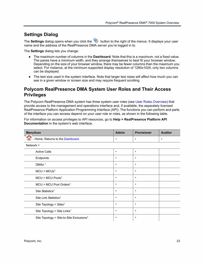
Settings DialogThe Settings dialog opens when you click the button to the right of the menus. It displays your user name and the address of the RealPresence DMA server you’re logged in to.
The Settings dialog lets you change:
● The maximum number of columns in the Dashboard. Note that this is a maximum, not a fixed value. The panes have a minimum width, and they arrange themselves to best fit your browser window. Depending on the size of your browser window, there may be fewer columns than the maximum you select. For instance, at the minimum supported display resolution of 1280x1024, only two columns can be displayed.
● The text size used in the system interface. Note that larger text sizes will affect how much you can see in a given window or screen size and may require frequent scrolling.
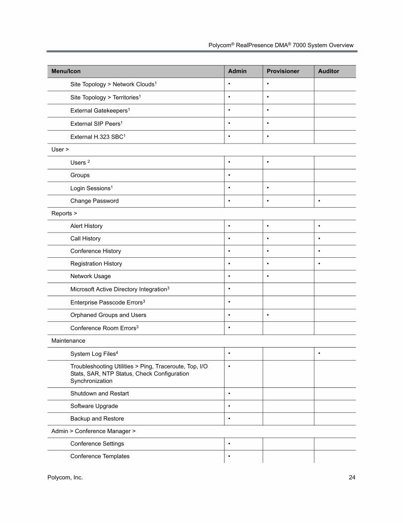
Polycom RealPresence DMA System User Roles and Their Access PrivilegesThe Polycom RealPresence DMA system has three system user roles (see User Roles Overview) that provide access to the management and operations interface and, if available, the separately licensed RealPresence Platform Application Programming Interface (API). The functions you can perform and parts of the interface you can access depend on your user role or roles, as shown in the following table.
For information on access privileges to API resources, go to Help > RealPresence Platform API Documentation in the system’s web interface.
Menu/Icon Admin Provisioner Auditor
- Home. Returns to the Dashboard. • • •
Network >
Active Calls • •
Endpoints • •
DMAs 1 • •
MCU > MCUs1 • •
MCU > MCU Pools1 • •
MCU > MCU Pool Orders1 • •
Site Statistics1 • •
Site Link Statistics1 • •
Site Topology > Sites1 • •
Site Topology > Site Links1 • •
Site Topology > Site-to-Site Exclusions1 • •
Polycom® RealPresence DMA® 7000 System Overview
Polycom, Inc. 24
Site Topology > Network Clouds1 • •
Site Topology > Territories1 • •
External Gatekeepers1 • •
External SIP Peers1 • •
External H.323 SBC1 • •
User >
Users 2 • •
Groups •
Login Sessions1 • •
Change Password • • •
Reports >
Alert History • • •
Call History • • •
Conference History • • •
Registration History • • •
Network Usage • •
Microsoft Active Directory Integration3 •
Enterprise Passcode Errors3 •
Orphaned Groups and Users • •
Conference Room Errors3 •
Maintenance
System Log Files4 • •
Troubleshooting Utilities > Ping, Traceroute, Top, I/O Stats, SAR, NTP Status, Check Configuration Synchronization
•
Shutdown and Restart •
Software Upgrade •
Backup and Restore •
Admin > Conference Manager >
Conference Settings •
Conference Templates •
Menu/Icon Admin Provisioner Auditor
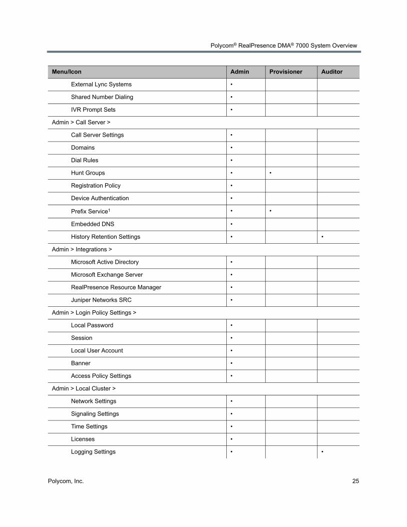
Polycom® RealPresence DMA® 7000 System Overview
Polycom, Inc. 25
External Lync Systems •
Shared Number Dialing •
IVR Prompt Sets •
Admin > Call Server >
Call Server Settings •
Domains •
Dial Rules •
Hunt Groups • •
Registration Policy •
Device Authentication •
Prefix Service1 • •
Embedded DNS •
History Retention Settings • •
Admin > Integrations >
Microsoft Active Directory •
Microsoft Exchange Server •
RealPresence Resource Manager •
Juniper Networks SRC •
Admin > Login Policy Settings >
Local Password •
Session •
Local User Account •
Banner •
Access Policy Settings •
Admin > Local Cluster >
Network Settings •
Signaling Settings •
Time Settings •
Licenses •
Logging Settings • •
Menu/Icon Admin Provisioner Auditor
Polycom® RealPresence DMA® 7000 System Overview
Polycom, Inc. 26
Open Source Software
License InformationRefer to the Polycom RealPresence DMA 7000 System Offer of Open Source Software for a list of the open source software packages used in the Polycom RealPresence DMA system, the applicable license for each, and the internet address where you can find it. To obtain the source code for any of these packages, e-mail your request to [email protected].
Modifying Open Source Code
The Polycom RealPresence DMA system software is not combined with or otherwise linked to any open source libraries, but the CentOS software is. The LGPL v2.1 license allows you to modify the LGPL code included with CentOS, recompile the modified code, and re-link it with the CentOS code. Note that although you’re free to modify the included LGPL modules in any way you wish, Polycom cannot be responsible if the changes you make impair the system.
To replace an LGPL library with your modified version
1 Obtain the source code for the module you want to modify.
SNMP Settings •
Alerting Settings •
Backup Settings •
Security Settings •
Certificates •
Help >
About DMA 7000 • • •
Help Contents • • •
RealPresence Platform API Documentation • • •
- Settings. Displays Settings dialog. • • •
- Log Out. Logs you out of the Polycom RealPresence DMA system.
• • •
- Help. Opens the online help topic for the page you’re viewing.
• • •
1. Provisioners have view-only access. 2. Must be an enterprise user to see enterprise users. Provisioners can’t add or remove roles or endpoints,
and can’t edit user accounts with explicitly assigned roles (Administrator, Provisioner, or Auditor), but can manage their conference rooms.
3. Must be an enterprise user to view this report. 4. Administrators can’t delete log archives.
Menu/Icon Admin Provisioner Auditor
Polycom® RealPresence DMA® 7000 System Overview
Polycom, Inc. 27
2 Modify the source code and compile it.
3 Go to Admin > Local Cluster > Security Settings, select Allow Linux console access, and click Update.
4 Contact Polycom Global Services for the root password for the Polycom RealPresence DMA server.
5 Use ssh to log into the server as root.
6 Upload the modified software via wget or scp.
7 Find the module you’re replacing and install the new version to that location.
8 Reboot the system.
Polycom, Inc. 28
Polycom RealPresence DMA System Initial Configuration Summary
This section describes the configuration tasks required to complete your implementation of a new Polycom® RealPresence® Distributed Media Application™ (DMA®) 7000 system once installation and initial network configuration are complete.
This section assumes you’ve completed the server configuration procedure in the Getting Started Guide (available at support.polycom.com), logged in to the Polycom RealPresence DMA system’s management interface, and verified that the Supercluster Status pane of the Dashboard shows (for a two-server configuration) two servers in the cluster, with healthy enterprise and private network status for both.
Initial configuration includes the following topics:
System configuration
● Add Required DNS Records for the Polycom RealPresence DMA System
● License the Polycom RealPresence DMA System
● Set Up Signaling
● Configure the Call Server and Optionally Create a Supercluster
● Set Up Security
● Set Up MCUs
● Connect to Microsoft Active Directory®
● Set Up Conference Templates
Confirming configuration
● Test the System
Each topic describes the task, provides background and overview information for it, and where appropriate, links to specific step-by-step procedures to follow in order to complete the task.
Note: Optional configuration tasks
These topics outline the configuration tasks that are generally required. You may wish to complete other optional configuration tasks, including:
• Enable cascading of conferences (see About Cascading).
• Configure calendaring service (see Microsoft Exchange Server Integration).
Integrate with a Juniper Networks SRC Series Session and Resource Control module to provide bandwidth assurance services (see Juniper Networks SRC Integration).
Polycom RealPresence DMA System Initial Configuration Summary
Polycom, Inc. 29
Add Required DNS Records for the Polycom RealPresence DMA System
Your Polycom RealPresence DMA system must be accessible by its host name(s), not just its IP address(es), so you (or your DNS administrator) must create A and/or AAAA records for IPv4 and IPv6, respectively, as well as the corresponding PTR records, on your DNS server(s).
A/AAAA records and PTR records that map each physical host name to the corresponding physical IP address and each virtual host name to the corresponding virtual IP address are mandatory, as are the corresponding PTR records that allow reverse DNS resolution of the system’s physical or virtual host name(s).
The DNS server(s) should also have entries for your Microsoft® Active Directory® server (if different from the DNS server) and any external gatekeepers or SIP peers.
You may need to create additional DNS records as described below.
Additional DNS Records for SIP ProxyTo support the use of your Polycom RealPresence DMA system as a SIP proxy server and ease future network administrative burdens, create the following DNS records (for each cluster in a supercluster, if applicable):
● Optionally, NAPTR records that describe the transport protocols supported by the SIP proxies at a domain and identify the preferred protocol. Configure these statically to match the system’s SIP transport protocol configuration.
Note: Consult an expert
If you’re not familiar with DNS administration, the creation of various kinds of DNS resource records (A/AAAA,NAPTR, NS, and SRV), your enterprise’s DNS implementation, and tuning for load balancing (if needed), please consult with someone who is.
Note: Fully qualified domain names
Depending on local DNS configuration, a host name could be the Polycom RealPresence DMA system’s fully qualified domain name (FQDN) or a shorter name that DNS can resolve.
For some features, such as Microsoft Exchange Server integration, it’s imperative that the FQDN can be resolved in DNS, especially by the Exchange server.
Polycom RealPresence DMA System Initial Configuration Summary
Polycom, Inc. 30
● SRV records for each transport protocol that identify the host names of the SIP proxies that service a particular domain. Configure these statically to point to the host names of the Call Servers in the domain. Here are example records for two clusters:
To enable access from the public internet, create corresponding SRV records, visible from outside the firewall, for the public address of each SIP session border controller (SBC).
For more information about the use of DNS in SIP, refer to RFCs 3263 and 2782.
Additional DNS Records for the H.323 GatekeeperTo support the use of your Polycom RealPresence DMA system as an H.323 gatekeeper and ease future network administrative burdens, create SRV records that identify the host names of the gatekeepers that service a particular domain. These records are necessary in order to enable the optional inbound URL dialing feature. Configure them statically to point to the host names of the Call Servers in the domain. Here are example records for two clusters:
To enable access from the public internet, create corresponding SRV records, visible from outside the firewall, for the public address of each H.323 session border controller (SBC).
For more information about the use of DNS in H.323, refer to the H.323 specification, Annex O, and the H.225.0 specification, Appendix IV.
Additional DNS Records for the Optional Embedded DNS FeatureTo support DNS publishing by your Polycom RealPresence DMA system’s embedded DNS servers (see Embedded DNS), a DNS NS record is needed for the physical host name of each server in each cluster in the supercluster. These records identify the Polycom RealPresence DMA system’s embedded DNS servers as authoritative for the specified logical host name. The logical host name you specify is the one in the Call server sub-domain controlled by RealPresence DMA field on the Embedded DNS page. Here are example records for two dual-server clusters:
callservers.example.com. 86400 IN NS dma-asia-server1.example.com.callservers.example.com. 86400 IN NS dma-asia-server2.example.com.callservers.example.com. 86400 IN NS dma-europe-server1.example.com.callservers.example.com. 86400 IN NS dma-europe-server2.example.com.
_sips._tcp.example.com. 86400 IN SRV 10 1001 5061 dma-asia.example.com._sips._tcp.example.com. 86400 IN SRV 10 1002 5061 dma-europe.example.com._sip._tcp.example.com. 86400 IN SRV 20 1001 5060 dma-asia.example.com._sip._tcp.example.com. 86400 IN SRV 20 1002 5060 dma-europe.example.com._sip._udp.example.com. 86400 IN SRV 30 1001 5060 dma-asia.example.com._sip._udp.example.com. 86400 IN SRV 30 1002 5060 dma-europe.example.com.
_h323ls._udp.example.com. 86400 IN SRV 0 1 1719 dma-asia.example.com._h323ls._udp.example.com. 86400 IN SRV 0 1 1719 dma-europe.example.com._h323cs._tcp.example.com. 86400 IN SRV 0 1 1720 dma-asia.example.com._h323cs._tcp.example.com. 86400 IN SRV 0 1 1720 dma-europe.example.com.
Polycom RealPresence DMA System Initial Configuration Summary
Polycom, Inc. 31
Your enterprise DNS must also have the zone callservers.example.com defined and be configured to forward requests for names in that zone to any of the clusters in the supercluster. The way you do this depends on the DNS server software being used.
Queries to the enterprise DNS for callservers.example.com are referred to the specified RealPresence DMA clusters. Their embedded DNS servers create and manage A records for each site in the site topology. When responsibility for a site moves from one cluster to another, the A records are updated so that the site’s domain name is mapped to the new cluster.
Verify That DNS Is Working for All AddressesTo confirm that DNS can resolve all the host names and/or FQDNs, ping each of them, either from a command prompt on the PC you’re using to access the system or from one of the clusters you’re setting up (go to Troubleshooting Utilities > Ping).
If you have access to a Linux PC and are familiar with the dig command, you can use it to query the enterprise DNS server to verify that all the records (A/AAAA, NS, and SRV) are present and look correct.
License the Polycom RealPresence DMA SystemA Polycom RealPresence DMA system is licensed at the cluster level (single-server or two-server). A cluster’s license specifies:
● The maximum number of concurrent calls that can touch the cluster. In a supercluster configuration, note that:
A single call may touch more than one cluster. It consumes a license on each cluster it touches.
Each cluster may be licensed for a different number of calls.
If your superclustering strategy (see About Superclustering) calls for a cluster to be primary for one territory and backup for another, it must be licensed for the call volume expected when it has to take over the territory for which it’s the backup.
● Whether access to the RealPresence® Platform Application Programming Interface (API) is enabled.
The API provides an API client application with programmatic access to the Polycom RealPresence DMA system (see RealPresence® Platform API). In a supercluster, all clusters must have the same API licensing status.
License the RealPresence DMA System, Appliance Edition
Note: Virtual host names cannot have NS records
NS records for the virtual host names must not exist.
Note: API licenses
An API license isn’t required in order for a Polycom RealPresence Resource Manager system to access the API. It’s only needed for a client application that you or a third party develop.
Polycom RealPresence DMA System Initial Configuration Summary
Polycom, Inc. 32
You should have received either one or two license numbers for each cluster, depending on whether you ordered a single-server or two-server cluster. You must obtain an activation key code for each server from the Polycom Resource Center (PRC):
1 Enter the server’s serial number and the license number that you were given for that server.
The PRC generates an activation key for that server.
2 For a two-server cluster, repeat the process using the other server’s serial number and its license number.
3 On the Licenses page of the RealPresence DMA system, install the activation keys to activate the licenses for your system (see Licenses).
License the RealPresence DMA System, Virtual EditionThe RealPresence DMA Virtual Edition is deployed and licensed through Polycom RealPresence Platform Director. You can view the licensing information for your system from the RealPresence DMA system user interface on the Admin > Local Cluster > Licenses page.
See the RealPresence Platform Director System Administrator’s Guide for more information.
Set Up SignalingSignaling setup includes configuring the following options:
● Enable H.323 signaling so that the Polycom RealPresence DMA system’s Call Server operates as a gatekeeper, which may include:
Enable gatekeeper discovery via H.323 multicast.
Enable and configure H.235 device authentication.
● Enable SIP signaling so that the Polycom RealPresence DMA system’s Call Server operates as a SIP registrar and proxy server, which may include:
Configure whether to support unencrypted SIP and whether to require mutual authentication (validation of client certificates).
Enable pass-through of ANAT signaling (RFC 4091 and RFC 4092).
Enable and configure SIP digest authentication.
Enable and configure special handling for untrusted (“unauthorized” or “guest”) calls from SIP session border controllers (SBCs).
● Enable WebRTC signaling.
To set up signaling, follow the procedure in Configure Signaling.
Caution: Do not generate both activation keys from the same physical server
An activation key is linked to a specific server’s serial number. For a two-server cluster, you must generate the activation key for each server using that server’s serial number. Licensing will fail if you generate both activation keys from the same server serial number.
Note: Local cluster not supported with virtual edition
The RealPresence DMA Virtual Edition does not support a two-server local cluster configuration. However, superclustering of individual RealPresence DMA Virtual Edition instances is fully supported in a virtual environment.
Polycom RealPresence DMA System Initial Configuration Summary
Polycom, Inc. 33
Configure the Call Server and Optionally Create a SuperclusterConfiguring the Polycom RealPresence DMA system’s Call Server function consists of the following high-level tasks:
1 Integrate with a Polycom RealPresence Resource Manager or CMA system (see RealPresence Resource Manager Integration) or enter site topology information (see Site Topology).
2 If deploying a supercluster of multiple geographically distributed Polycom RealPresence DMA clusters:
a Set the Security Configuration page security options before superclustering (see Security Settings). But wait until after superclustering to do the rest of the security setup tasks.
b Depending on security settings, you may need to install certificates before superclustering (see Certificate Procedures).
c Create a supercluster (see About Superclustering) and configure supercluster options.
3 Create territories and assign sites to them (if you integrated with a Polycom RealPresence Resource Manager or CMA system, this must be done on that system). Assign the primary and backup cluster responsible for each territory, and designate which territories can host conference rooms (see Territories).
4 Add any external devices, such as a neighbor gatekeeper or SIP peer (see Call Server Configuration).
5 Configure the dial plan (see Dial Rules).
Set Up SecurityThe first step in securing your Polycom RealPresence DMA system is to locate it in a secure data center with controlled access, but that topic is beyond the scope of this document.
Secure setup of the Polycom RealPresence DMA system consists of the following high-level tasks (some of which assume you’re integrating with Active Directory and some of which overlap with other initial setup topics):
1 As the default local administrative user (admin), create a local user account for yourself with the Administrator role, log in using that account, and delete the admin user account. See Adding Users Overview and Users Procedures.
2 Create the Active Directory service account (read-only user account) that the Polycom RealPresence DMA system will use to read and integrate with Active Directory. See Active Directory Integration Procedure.
3 Assign the Administrator role to your named enterprise account, and remove the Polycom RealPresence DMA system’s user roles (see User Roles Overview) from the service account used to integrate with Active Directory. See Connect to Microsoft Active Directory® and Microsoft Active Directory® Integration.
4 Log out and log back in using your enterprise user ID and password.
5 Verify that the expected enterprise users are available in the Polycom RealPresence DMA system and that conference room IDs were successfully created for them. If necessary, adjust integration settings and correct errors. See Microsoft Active Directory® Integration, Users Procedures, and Conference Room Errors Report.
Polycom RealPresence DMA System Initial Configuration Summary
Polycom, Inc. 34
6 Obtain and install a security certificate from a trusted certificate authority. See Security Certificates Overview and Certificate Procedures.
7 Configure as needed various login policy settings (see Login Policy Settings) and optionally, a management access whitelist (see Access Policy Settings).
8 Document your current configuration for comparison in the future. We recommend saving screen captures of all the configuration pages.
9 Manually create a backup, download it, and store it in a safe place. See Backing Up and Restoring.
Set Up MCUs
Make sure your MCUs are configured to accept encrypted (HTTPS) management connections (required for maximum or high security mode).
Make sure that each MCU is in a site belonging to a territory for which the Polycom RealPresence DMA system is responsible. If you’re deploying a supercluster (see Configure the Call Server and Optionally Create a Supercluster and About Superclustering), make sure that each territory has a primary and backup cluster assigned to it. If the primary cluster becomes unavailable, the MCUs registered to it can re-register to the backup.
If you’re deploying a supercluster, verify that you’ve enabled the hosting of conference rooms in the right territories and assigned clusters to those territories. See Configure the Call Server and Optionally Create a Supercluster.
Standalone MCUs can register themselves to the Polycom RealPresence DMA system’s Call Server. To make an MCU available as a conferencing resource, either add it to the appropriate Polycom RealPresence DMA cluster’s Conference Manager manually or, if it’s already registered with the Call Server, edit its entry to enable it for conference rooms and provide the additional configuration information required. See MCU Management.
You must organize MCUs configured as conferencing resources into one or more MCU pools (logical groupings of media servers). Then, you can define one or more MCU pool orders that specify the order of preference in which MCU pools are used.
Note: MCUs and RealPresence DMA system interaction
The Polycom RealPresence DMA system can interact with MCUs, or media servers, in either or both of the following two ways:
• MCUs may be made available to system’s Conference Manager to manage for multi-point conferencing (hosting virtual meeting rooms, or VMRs).
• MCUs may be registered with the system’s Call Server as standalone MCUs and/or gateways.
This configuration summary assumes you want to do both.
Polycom RealPresence DMA System Initial Configuration Summary
Polycom, Inc. 35
Every conference room (VMR) is associated with an MCU pool order. The pool(s) to which an MCU belongs, and the pool order(s) to which a pool belongs, are used to determine which MCU is used to host a conference. See MCU Pools and MCU Pool Orders for information about how to use pools and pool orders, as well as the rules that the system uses to choose an MCU for a user.
The Polycom RealPresence DMA system uses conference templates to define the conferencing experience associated with a conference room or enterprise group. You can create standalone templates (recommended), setting the conferencing parameters directly in the Polycom RealPresence DMA system, or link templates to RealPresence® Collaboration Server or RMX conference profiles (see Conference Templates).
Both methods allow you to specify most conference parameters:
● General information such as line rate, encryption, auto termination, and H.239 settings
● Video settings such as mode (presentation or lecture) and layout
● IVR settings
● Conference recording settings
If you want to create RealPresence DMA system templates linked to conference profiles on the RealPresence Collaboration Server or RMX MCUs, make sure the profiles used by the Polycom RealPresence DMA system exist on all the MCUs and are defined the same on all of them.
Connect to Microsoft Active Directory®
Connecting to Microsoft® Active Directory® simplifies the task of deploying conferencing to a large organization. All Polycom RealPresence DMA system access to the Active Directory server is read-only and minimally impacts the directory performance. See Microsoft Active Directory® Integration.
Before integrating with Active Directory, be sure that one or more DNS servers are specified (this should have been done during installation and initial setup). See Network Settings.
If you’re deploying a supercluster of multiple geographically distributed Polycom RealPresence DMA clusters, verify that you’ve assigned clusters to the territories in your site topology (see Configure the Call
Note: Resource management and MCU pools
If you have a Polycom RealPresence Resource Manager system that’s going to use the RealPresence DMA system API to schedule conferences on the RealPresence DMA system’s conferencing resources (MCU pools), you must create MCU pools and pool orders specifically for the use of the RealPresence Resource Manager system. The pool orders should be named in such a way that:
• They appear at the top of the pool order list presented in the RealPresence Resource Manager system.
• Users of that system will understand that they should choose one of those pool orders.
When adding an MCU for use by a RealPresence Resource Manager system, the option Enable for conference rooms should not be selected in the settings dialog for that MCU.
Note: Consult an expert
If you’re not knowledgeable about enterprise directories in general and your specific implementation in particular, please consult with someone who is. Active Directory integration is a non-trivial matter.
Polycom RealPresence DMA System Initial Configuration Summary
Polycom, Inc. 36
Server and Optionally Create a Supercluster) and decide which cluster is to be responsible for Active Directory integration.
Active Directory integration automatically makes the enterprise users (directory members) into Conferencing Users in the Polycom RealPresence DMA system, and can assign each of them a conference room (virtual meeting room, or VMR). The conference room IDs are typically generated from the enterprise users’ phone numbers.
Once the Polycom RealPresence DMA system is integrated with Active Directory, it reads the directory information nightly, so that user and group information is updated automatically as people join and leave the organization. The system caches certain data from Active Directory. In a superclustered system, one cluster is responsible for updating the cache, which is shared with all the clusters.
Between updates, clusters access the directory only to authenticate passwords (for instance, for management interface login); all other user information (such as user search results) comes from the cache. You can manually update the cache at any time.
Enterprise groups can have their own conference templates that provide a custom conferencing experience (see Conference Templates). They can also have their own MCU pool order, which preferentially routes conferences to certain MCUs (see MCU Pool Orders).
You can assign Polycom RealPresence DMA system roles to an enterprise group, applying the roles to all members of the group and enabling them to log into the Polycom RealPresence DMA system’s management interface with their standard network user names and passwords.
See User Roles Overview, Groups, and Enterprise Groups Procedures.
There are security concerns that need to be addressed regarding user accounts, whether local or enterprise. See the high-level process described in Set Up Security.
Set Up Conference TemplatesThe Polycom RealPresence DMA system uses conference templates and global conference settings to manage system and conference behavior, and it has a default conference template and default global conference settings.
After you’ve added MCUs to the system, you may want to change the global conference settings or create additional templates that specify different conference properties.
If you integrate with Active Directory, you can use templates to provide customized conferencing experiences for various enterprise groups.
When you add a custom conference room to a user (either local or enterprise), you can choose which template that conference room uses.
To add conference templates, see Conference Templates Procedures. To change conference settings, see Conference Settings. To customize the conferencing experience for an enterprise group, see Enterprise Groups Procedures.
Note: Manually add conference rooms
Creating conference rooms for enterprise users is optional. If you want to integrate with Active Directory to load user and group information into the Polycom RealPresence DMA system, but don’t want to give all users the ability to host conferences, you can do so. You can manually add conference rooms for selected users at any time. See Conference Rooms Procedures.
Polycom RealPresence DMA System Initial Configuration Summary
Polycom, Inc. 37
Test the SystemOn the Signaling Settings page (see Signaling Settings), verify that:
● If you enabled H.323, the H.323 Signaling Status section indicates that the signaling status is Active and the port assignments are correct.
● If you enabled SIP, the SIP Signaling Status section shows that the correct protocols and listening ports are enabled.
Have some endpoints register with the Polycom RealPresence DMA Call Server and make point-to-point calls to each other.
On the Dashboard (see Dashboard), verify that:
● The information in the Cluster Info pane looks correct, including the time, network settings, and system resource information.
● The Supercluster Status pane shows the correct number of servers and clusters, and the network interfaces that should be working (depending on your IP type and split network settings) are up (green up arrow) and in full duplex mode, with the speed correct for your enterprise network.
● The Call Server Registrations pane shows that the endpoints that attempted to register did so successfully.
● The Call Server Active Calls pane shows that the endpoints that made calls did so successfully, and the call limits per cluster and total are correct for your licenses.
● The Conference Manager MCUs pane shows that the MCUs you added are connected and in service.
● The information on the Active Directory Integration pane looks correct, including the status, cache refresh data, and enterprise conference room count.
Set up some multipoint conferences by having endpoints dial into enterprise users’ conference rooms (preferably including a custom conference room). Verify that conferencing works satisfactorily, that the system status is good, and that the Conference Manager Usage pane accurately presents the status.
When you’re satisfied that the Polycom RealPresence DMA system is configured and working properly, manually create a backup, download it, and store it in a safe place. See Backing Up and Restoring.
Polycom, Inc. 38
System Security
This section describes the following Polycom® RealPresence® Distributed Media Application™ (DMA®) 7000 system security topics:
● Security Certificates Overview
● Certificate Settings
● Certificate Procedures
● Security Settings
● The Consequences of Enabling Maximum Security Mode
● Login Policy Settings
● Reset System Passwords
Security Certificates Overview
How Certificates WorkX.509 certificates are a security technology that assists networked computers in determining whether to trust each other.
● A single, centralized certificate authority (CA) is established. Typically, this is either an enterprise’s IT department or a commercial certificate authority.
● Each computer on the network is configured to trust the central certificate authority.
● Each server on the network has a public certificate that identifies it.
● The certificate authority signs the public certificates of those servers that clients should trust.
● When a client connects to a server, the server shows its signed public certificate to the client. Trust is established because the certificate has been signed by the certificate authority, and the client has been configured to trust the certificate authority.
Forms of Certificates Accepted by the Polycom RealPresence DMA SystemX.509 certificates come in several forms (encoding and protocol). The following table shows the forms that can be installed in the Polycom RealPresence DMA system.
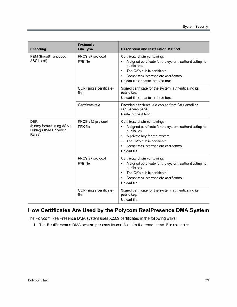
System Security
Polycom, Inc. 39
How Certificates Are Used by the Polycom RealPresence DMA SystemThe Polycom RealPresence DMA system uses X.509 certificates in the following ways:
1 The RealPresence DMA system presents its certificate to the remote end. For example:
Encoding Protocol / File Type Description and Installation Method
PEM (Base64-encoded ASCII text)
PKCS #7 protocol
P7B file
Certificate chain containing:
• A signed certificate for the system, authenticating its public key.
• The CA’s public certificate.
• Sometimes intermediate certificates.
Upload file or paste into text box.
CER (single certificate) file
Signed certificate for the system, authenticating its public key.
Upload file or paste into text box.
Certificate text Encoded certificate text copied from CA’s email or secure web page.
Paste into text box.
DER (binary format using ASN.1 Distinguished Encoding Rules)
PKCS #12 protocol
PFX file
Certificate chain containing:
• A signed certificate for the system, authenticating its public key.
• A private key for the system.
• The CA’s public certificate.
• Sometimes intermediate certificates.
Upload file.
PKCS #7 protocol
P7B file
Certificate chain containing:
• A signed certificate for the system, authenticating its public key.
• The CA’s public certificate.
• Sometimes intermediate certificates.
Upload file.
CER (single certificate) file
Signed certificate for the system, authenticating its public key.
Upload file.

System Security
Polycom, Inc. 40
When a user logs into the Polycom RealPresence DMA system’s browser-based management interface, the Polycom RealPresence DMA system (server) offers an X.509 certificate to identify itself to the browser (client).
The Polycom RealPresence DMA system’s certificate must have been signed by a certificate authority (see Certificate Procedures).
The browser must be configured to trust that certificate authority (beyond the scope of this documentation).
If trust can’t be established, most browsers allow connection anyway, but display a dialog to the user, requesting permission.
When the Polycom RealPresence DMA system connects to a Microsoft Active Directory server, it may present a certificate to the server to identify itself.
If Active Directory is configured to require a client certificate (this is not the default), the Polycom RealPresence DMA system offers the same SSL server certificate that it offers to browsers connecting to the system management interface. Active Directory must be configured to trust the certificate authority, or it rejects the certificate and the connection fails.
When the Polycom RealPresence DMA system connects to a Microsoft Exchange server (if the calendaring service is enabled; see Microsoft Exchange Server Integration), it may present a certificate to the server to identify itself.
Unless the Allow unencrypted calendar notifications from Exchange server security option is enabled (see Security Settings), the Polycom RealPresence DMA system offers the same SSL server certificate that it offers to browsers connecting to the system management interface. The Microsoft Exchange server must be configured to trust the certificate authority. Otherwise, the Microsoft Exchange Server integration status (see Dashboard) remains Subscription pending indefinitely, the Polycom RealPresence DMA system does not receive calendar notifications, and incoming meeting request messages are only processed approximately every 4 minutes.
2 The RealPresence DMA system validates the certificate of a remote server. For example:
When the Polycom RealPresence DMA system connects to a Polycom MCU configured for secure communications, a certificate may be used to identify the MCU (server) to the Polycom RealPresence DMA system (client). This can be configured on the RealPresence DMA system.
When performing call signaling requiring TLS, the Polycom RealPresence DMA system presents its certificate to the connecting client (one-way TLS). If the Require mutual authentication (validation of client certificates) SIP Settings option is enabled (see Signaling Settings), the both ends validate each other’s certificates (mutual TLS).
3 The RealPresence DMA system validates the certificate of a client. For example:
For incoming SIP connections, the RealPresence DMA system may check the client’s certificate. This can be configured on the RealPresence DMA system.
System Security
Polycom, Inc. 41
Frequently Asked QuestionsQ. Is it secure to send my certificate request through email?
A. Yes. The certificate request, signed certificate, intermediate certificates, and authority certificates that are sent through email don’t contain any secret information. There is no security risk in letting untrusted third parties see their contents.
As a precaution, you can verify the certificate fingerprints (which can be found in the Certificate Details popup) with the certificate authority via telephone. This ensures that a malicious third party didn’t substitute a fake email message with fake certificates.
Q. Why doesn’t the information on the Certificate Details popup match the information that I filled out in the signing request form?
A. Commercial certificate authorities routinely replace the organizational information in the certificate with their own slightly different description of your organization.
Q. I re-installed the Polycom RealPresence DMA system software. Why can’t I re-install my signed public certificate?
A. X.509 certificates use public/private key pair technology. The public key is contained in your public certificate and is provided to any web browser that asks for it. The private key never leaves the Polycom RealPresence DMA system.
As part of software installation, the Polycom RealPresence DMA system generates a new public/private key pair. The public key from your old key pair can’t be used with the new private key.
To re-use your signed public certificate, try restoring from backup. Both the public and private keys are saved as part of a backup file. Alternatively, if the certificate you want to reinstall is a PKCS#12 certificate, it contains a private key and will replace both the public key and the private key generated at installation time.
See also:
System Security
Certificate Settings
Certificate Procedures
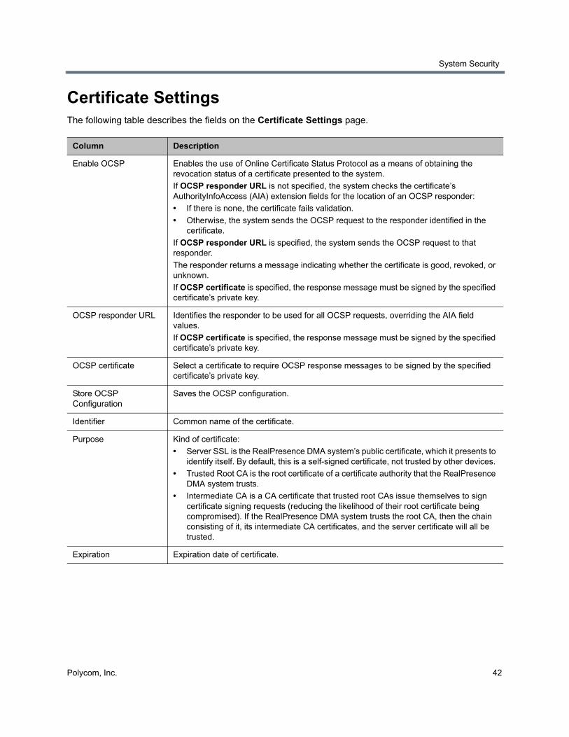
System Security
Polycom, Inc. 42
Certificate SettingsThe following table describes the fields on the Certificate Settings page.
Column Description
Enable OCSP Enables the use of Online Certificate Status Protocol as a means of obtaining the revocation status of a certificate presented to the system.
If OCSP responder URL is not specified, the system checks the certificate’s AuthorityInfoAccess (AIA) extension fields for the location of an OCSP responder:
• If there is none, the certificate fails validation.
• Otherwise, the system sends the OCSP request to the responder identified in the certificate.
If OCSP responder URL is specified, the system sends the OCSP request to that responder.
The responder returns a message indicating whether the certificate is good, revoked, or unknown.
If OCSP certificate is specified, the response message must be signed by the specified certificate’s private key.
OCSP responder URL Identifies the responder to be used for all OCSP requests, overriding the AIA field values.
If OCSP certificate is specified, the response message must be signed by the specified certificate’s private key.
OCSP certificate Select a certificate to require OCSP response messages to be signed by the specified certificate’s private key.
Store OCSP Configuration
Saves the OCSP configuration.
Identifier Common name of the certificate.
Purpose Kind of certificate:
• Server SSL is the RealPresence DMA system’s public certificate, which it presents to identify itself. By default, this is a self-signed certificate, not trusted by other devices.
• Trusted Root CA is the root certificate of a certificate authority that the RealPresence DMA system trusts.
• Intermediate CA is a CA certificate that trusted root CAs issue themselves to sign certificate signing requests (reducing the likelihood of their root certificate being compromised). If the RealPresence DMA system trusts the root CA, then the chain consisting of it, its intermediate CA certificates, and the server certificate will all be trusted.
Expiration Expiration date of certificate.
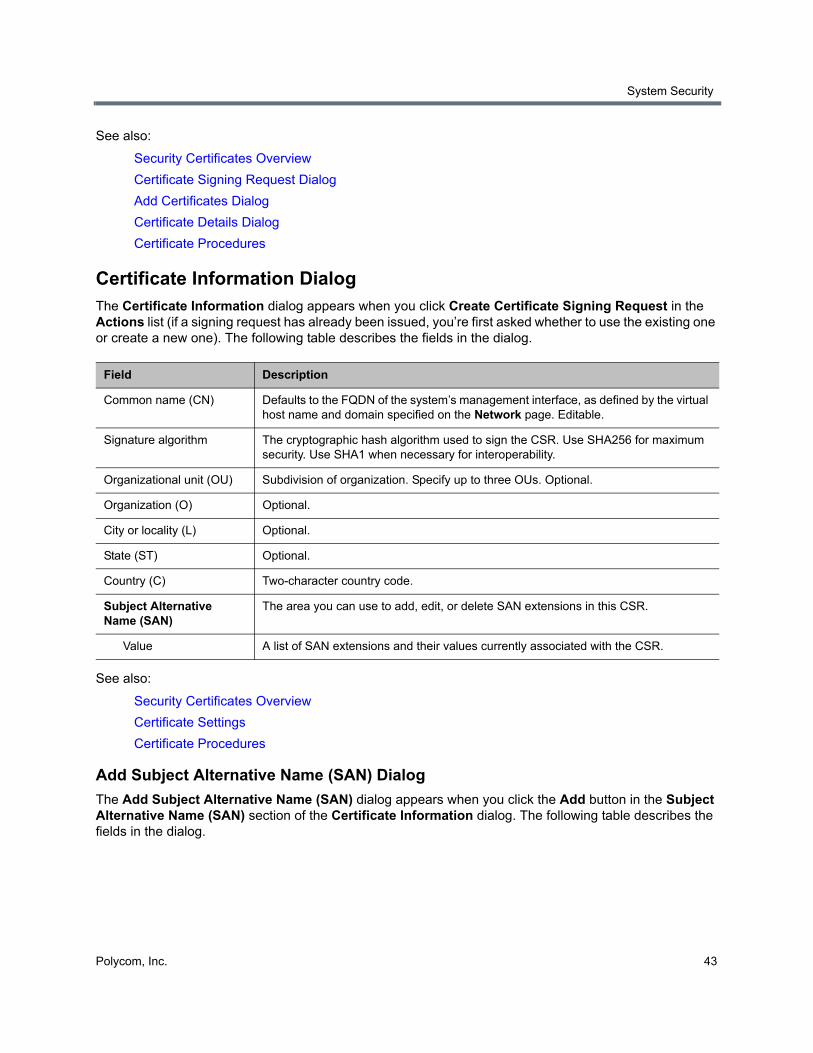
System Security
Polycom, Inc. 43
See also:
Security Certificates Overview
Certificate Signing Request Dialog
Add Certificates Dialog
Certificate Details Dialog
Certificate Procedures
Certificate Information Dialog The Certificate Information dialog appears when you click Create Certificate Signing Request in the Actions list (if a signing request has already been issued, you’re first asked whether to use the existing one or create a new one). The following table describes the fields in the dialog.
See also:
Security Certificates Overview
Certificate Settings
Certificate Procedures
Add Subject Alternative Name (SAN) Dialog
The Add Subject Alternative Name (SAN) dialog appears when you click the Add button in the Subject Alternative Name (SAN) section of the Certificate Information dialog. The following table describes the fields in the dialog.
Field Description
Common name (CN) Defaults to the FQDN of the system’s management interface, as defined by the virtual host name and domain specified on the Network page. Editable.
Signature algorithm The cryptographic hash algorithm used to sign the CSR. Use SHA256 for maximum security. Use SHA1 when necessary for interoperability.
Organizational unit (OU) Subdivision of organization. Specify up to three OUs. Optional.
Organization (O) Optional.
City or locality (L) Optional.
State (ST) Optional.
Country (C) Two-character country code.
Subject Alternative Name (SAN)
The area you can use to add, edit, or delete SAN extensions in this CSR.
Value A list of SAN extensions and their values currently associated with the CSR.
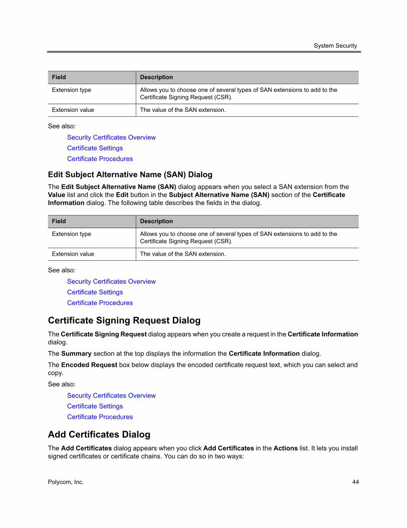
System Security
Polycom, Inc. 44
See also:
Security Certificates Overview
Certificate Settings
Certificate Procedures
Edit Subject Alternative Name (SAN) Dialog
The Edit Subject Alternative Name (SAN) dialog appears when you select a SAN extension from the Value list and click the Edit button in the Subject Alternative Name (SAN) section of the Certificate Information dialog. The following table describes the fields in the dialog.
See also:
Security Certificates Overview
Certificate Settings
Certificate Procedures
Certificate Signing Request Dialog The Certificate Signing Request dialog appears when you create a request in the Certificate Information dialog.
The Summary section at the top displays the information the Certificate Information dialog.
The Encoded Request box below displays the encoded certificate request text, which you can select and copy.
See also:
Security Certificates Overview
Certificate Settings
Certificate Procedures
Add Certificates Dialog The Add Certificates dialog appears when you click Add Certificates in the Actions list. It lets you install signed certificates or certificate chains. You can do so in two ways:
Field Description
Extension type Allows you to choose one of several types of SAN extensions to add to the Certificate Signing Request (CSR).
Extension value The value of the SAN extension.
Field Description
Extension type Allows you to choose one of several types of SAN extensions to add to the Certificate Signing Request (CSR).
Extension value The value of the SAN extension.

System Security
Polycom, Inc. 45
● Upload a PFX, PEM, or P7B certificate file.
● Paste PEM-format certificate text into the dialog.
The following table describes the fields in the dialog.
See also:
Security Certificates Overview
Certificate Settings
Certificate Procedures
Certificate Details Dialog The Certificate Details dialog appears when you click Display Details in the Actions list. It displays information about the certificate selected in the list, as outlined in the following table.
See also:
Security Certificates Overview
Certificate Settings
Field Description
Upload certificate If checked, the Password field and Upload file button enable you to upload a PFX, PEM, or P7B certificate file.
Password Enter the password, if any, assigned to the certificate file when it was created.
Upload file Click the button to browse to the file you want to upload.
Paste certificate If checked, the text field below enables you to paste in the text of PEM certificate files.
Section Description
Certificate Info Purpose and alias of the certificate.
Issued To Information about the entity to which the certificate was issued and the certificate serial number.
Issued By Information about the issuer.
Validity Issue and expiration dates.
Fingerprints SHA1 and MD5 fingerprints (checksums) for confirming certificate.
Subject Alternative Names
Additional identities bound to the subject of the certificate.
For the Polycom RealPresence DMA system, this should include the virtual and physical FQDNs, short host names, and IP addresses of the system.
Extended Key Usage Indicates the purposes for which the certificate can be used.
The Polycom RealPresence DMA system’s certificate is used for both server and client connections, so this should always contain at least serverAuth and clientAuth.
System Security
Polycom, Inc. 46
Certificate Procedures Certificate procedures include the following:
● Install your chosen certificate authority’s public certificate, if necessary, so that the Polycom RealPresence DMA system trusts that certificate authority.
● Create a certificate signing request to submit to the certificate authority.
● Install a public certificate signed by your certificate authority that identifies the Polycom RealPresence DMA system.
● Remove a signed certificate or a certificate authority’s certificate.
Install a Certificate Authority’s Certificate This procedure is not necessary if you obtain a certificate chain that includes a signed certificate for the Polycom RealPresence DMA system, your certificate authority’s public certificate, and any intermediate certificates.
Use this procedure to add a trusted certificate authority, either an in-house or commercial CA.
To install a certificate for a trusted root CA
1 Go to Admin > Local Cluster > Certificates.
The installed certificates are listed. The Trusted Root CA entries, if any, represent the certificate authorities whose public certificates are already installed on the RealPresence DMA system and are thus trusted.
Note: Obtaining certificates for Microsoft environments
If you’re configuring the Polycom RealPresence DMA system to support Polycom’s solution for the Microsoft OCS or Lync environment, you can use Microsoft’s Certificate Wizard to request and obtain a PFX file (a password-protected PKCS12 file containing a private key and public key for the system, and the CA’s certificate).
Once you have the PFX file, you’re ready to install it.
See Polycom’s solution deployment guide for information about using the Certificate Wizard and other steps needed to implement the solution.
Caution: Installing or removing certificates requires a restart
Installing or removing certificates requires a system restart and terminates all active conferences.
When you install or remove a certificate, the change is made to the certificate store immediately, but the system can’t implement the change until it restarts and reads the changed certificate store.
For your convenience, you’re not required to restart and apply a change immediately. This permits you to perform multiple installs or removals before restarting and applying the changes. But when you’re finished making changes, you must select Restart to Apply Saved Changes to restart the system and finish your update. Before you begin, make sure there are no active conferences and you’re prepared to restart the system when you’re finished.
System Security
Polycom, Inc. 47
2 If you’re using a certificate authority that isn’t listed, obtain a copy of your certificate authority’s public certificate.
The certificate must be either a single X.509 certificate or a PKCS#7 certificate chain. If it’s ASCII text, it’s in PEM format, and starts with the text -----BEGIN CERTIFICATE-----. If it’s a file, it can be either PEM or DER encoded.
3 In the Actions list, select Add Certificates.
4 In the Add Certificates dialog, do one of the following:
If you have a file, click Upload certificate, enter the password (if any) for the file, and browse to the file or enter the path and file name.
If you have PEM-format text, copy the certificate text, click Paste certificate, and paste it into the text box below.
5 Click OK.
6 Verify that the certificate appears in the list as a Trusted Root CA.
7 Click Restart to Apply Saved Changes, and when asked to confirm that you want to restart the system so that certificate changes can take effect, click OK.
See also:
Security Certificates Overview
Certificate Settings
Certificate Procedures
Create a Certificate Signing Request When you create a certificate signing request (CSR) from the Admin > Local Cluster > Certificates page, the system populates the CSR with the data that you enter in the Certificate Information dialog, including Subject Alternative Name (SAN) extensions. The default system-generated SAN extensions, which may vary depending on your configuration, are shown in the Value list. You can change these values or add more extensions if needed. Polycom strongly recommends that you not delete the default SAN extensions; this may cause the resulting certificate to not work with your configuration.
When you create a CSR, if you include the SAN extensions listed in the Optional Fields column, the resulting certificate will allow users to access the system using an abbreviated name without authentication errors. Ensure that you use a CA that can accept all of the CSR fields and SAN extensions required for your configuration. The following table lists required and optional fields for single-server, clustered, and superclustered configurations.
Note: FQDN recommended for domain names
Polycom recommends the use of the system’s fully qualified domain name (FQDN) for required SAN-DNS extensions. Newer CA regulations may cause your CA to reject the CSR if only short host names are used.
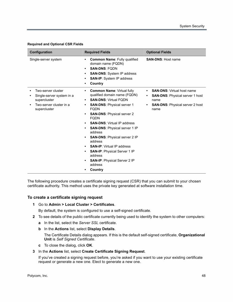
System Security
Polycom, Inc. 48
The following procedure creates a certificate signing request (CSR) that you can submit to your chosen certificate authority. This method uses the private key generated at software installation time.
To create a certificate signing request
1 Go to Admin > Local Cluster > Certificates.
By default, the system is configured to use a self-signed certificate.
2 To see details of the public certificate currently being used to identify the system to other computers:
a In the list, select the Server SSL certificate.
b In the Actions list, select Display Details.
The Certificate Details dialog appears. If this is the default self-signed certificate, Organizational Unit is Self Signed Certificate.
c To close the dialog, click OK.
3 In the Actions list, select Create Certificate Signing Request.
If you’ve created a signing request before, you’re asked if you want to use your existing certificate request or generate a new one. Elect to generate a new one.
Required and Optional CSR Fields
Configuration Required Fields Optional Fields
Single-server system • Common Name: Fully qualified domain name (FQDN)
• SAN-DNS: FQDN
• SAN-DNS: System IP address
• SAN-IP: System IP address
• Country
SAN-DNS: Host name
• Two-server cluster
• Single-server system in a supercluster
• Two-server cluster in a supercluster
• Common Name: Virtual fully qualified domain name (FQDN)
• SAN-DNS: Virtual FQDN
• SAN-DNS: Physical server 1 FQDN
• SAN-DNS: Physical server 2 FQDN
• SAN-DNS: Virtual IP address
• SAN-DNS: Physical server 1 IP address
• SAN-DNS: Physical server 2 IP address
• SAN-IP: Virtual IP address
• SAN-IP: Physical Server 1 IP address
• SAN-IP: Physical Server 2 IP address
• Country
• SAN-DNS: Virtual host name
• SAN-DNS: Physical server 1 host name
• SAN-DNS: Physical server 2 host name
System Security
Polycom, Inc. 49
4 In the Certificate Information dialog, enter the identifying information for your Polycom RealPresence DMA system (see Certificate Information Dialog).
5 Click Add to open the Add Subject Alternative Name (SAN) dialog.
6 Select an Extension type from the list and enter the associated Extension value.
7 Click OK to close the dialog.
8 Repeat steps 5-7 as needed to add SAN extensions required for your configuration.
9 To change an existing SAN extension, select it from the Value list and click Edit.
10 To delete a SAN value, select it from the Value list and click Delete.
11 Click OK to generate the CSR.
The Certificate Signing Request dialog displays the encoded request (see Certificate Signing Request Dialog).
12 Copy the entire contents of the Encoded Request box (including the text -----BEGIN NEW CERTIFICATE REQUEST----- and -----END NEW CERTIFICATE REQUEST-----) and submit it to your certificate authority.
Depending on the certificate authority, your CSR may be submitted via email or by pasting into a web page.
13 Click OK to close the dialog.
When your certificate authority has processed your request, it sends you a signed public certificate for your Polycom RealPresence DMA system. Some certificate authorities also send intermediate certificates and/or root certificates. Depending on the certificate authority, these certificates may arrive as e-mail text, e-mail attachments, or be available on a secure web page.
The Polycom RealPresence DMA system accepts PKCS#7 or PKCS#12 certificate chains or single certificates.
See also:
Security Certificates Overview
Certificate Settings
Certificate Procedures
Install a Certificate in the RealPresence DMA System The procedure below installs the certificate or certificate chain provided by the certificate authority. It assumes that you’ve received the certificate or certificate chain in one of the following forms:
● A PFX, P7B, or single certificate file that you’ve saved on your computer.
● PEM-format encoded text that you received in an e-mail or on a secure web page.
Caution: Some CSR fields should not be modified
When you submit the CSR to your CA, make sure that the CA doesn’t modify any of the predefined SAN fields or the X.509v3 Key Usage or Extended Key Usage fields. Changes to these fields may make your system unusable. Contact Polycom technical support if you have any questions about this.
System Security
Polycom, Inc. 50
To install a signed certificate that identifies the Polycom RealPresence DMA system
1 When you receive your certificate(s), return to Admin > Local Cluster > Certificates.
2 In the Actions list, select Add Certificates.
3 In the Add Certificates dialog, do one of the following:
If you have a PFX, P7B, or single certificate file, click Upload certificate, enter the password (if any) for the file, and browse to the file or enter the path and file name.
If you have PEM-format text, copy the certificate text, click Paste certificate, and paste it into the text box below. You can paste multiple PEM certificates one after the other.
4 Click OK.
5 To verify that the new signed certificate has replaced the default self-signed certificate:
a In the list of certificates, once again select the Server SSL certificate.
b In the Actions list, select Display Details.
The Certificate Details dialog appears.
c Confirm from the information under Issued To and Issued By that the self-signed default certificate has been replaced by your signed public certificate from the certificate authority.
d Click OK to close the dialog.
6 Click Restart to Apply Saved Changes, and when asked to confirm that you want to restart the system so that certificate changes can take effect, click OK.
See also:
Security Certificates Overview
Certificate Settings
Certificate Procedures
Remove a Certificate from the RealPresence DMA System There are two kinds of certificate removal:
● Removing the certificate of a Trusted Root CA so that the system no longer trusts certificates signed by that certificate authority.
● Removing the signed certificate currently in use as the Server SSL certificate so that the system reverts to using the default self-signed Server SSL certificate.
Removing a signed certificate also removes the certificate of the Trusted Root CA that signed it, along with any intermediate certificates provided by that certificate authority.
Caution: Installing or removing certificates requires a restart
Installing or removing certificates requires a system restart and terminates all active conferences.
When you install or remove a certificate, the change is made to the certificate store immediately, but the system can’t implement the change until it restarts and reads the changed certificate store.
For your convenience, you’re not required to restart and apply a change immediately. This permits you to perform multiple installs or removals before restarting and applying the changes. But when you’re finished making changes, you must select Restart to Apply Saved Changes to restart the system and finish your update. Before you begin, make sure there are no active conferences and you’re prepared to restart the system when you’re finished.
System Security
Polycom, Inc. 51
Both procedures are described below.
To remove a Trusted Root CA’s certificate
1 Go to Admin > Local Cluster > Certificates.
2 In the certificates list, select the certificate you want to delete.
3 In the Actions list, select Display Details and confirm that you’ve selected the correct certificate. Then click OK.
4 In the Actions list, select Delete Certificate.
5 When asked to confirm, click Yes.
A dialog informs you that the certificate has been deleted.
6 Click OK.
7 Click Restart to Apply Saved Changes, and when asked to confirm that you want to restart the system so that certificate changes can take effect, click OK.
To remove a signed certificate and revert to the default self-signed certificate
1 Go to Certificates.
2 In the Actions list, select Revert to Default Certificate.
3 When asked to confirm, click Yes.
A dialog informs you that the system has reverted to a self-signed certificate.
4 Click OK.
5 Click Restart to Apply Saved Changes, and when asked to confirm that you want to restart the system so that certificate changes can take effect, click OK.
6 After the system restarts, log back in, return to Admin > Local Cluster > Certificates, and verify that the system has reverted to the default self-signed certificate:
a In the list of certificates, select the Server SSL certificate.
b In the Actions list, select Display Details.
The Certificate Details dialog appears.
c Confirm from the information under Issued To and Issued By that the default self-signed certificate has replaced the CA-signed certificate.
d Click OK to close the dialog.
Caution: Installing or removing certificates requires a restart
Installing or removing certificates requires a system restart and terminates all active conferences.
When you install or remove a certificate, the change is made to the certificate store immediately, but the system can’t implement the change until it restarts and reads the changed certificate store.
For your convenience, you’re not required to restart and apply a change immediately. This permits you to perform multiple installs or removals before restarting and applying the changes. But when you’re finished making changes, you must select Restart to Apply Saved Changes to restart the system and finish your update. Before you begin, make sure there are no active conferences and you’re prepared to restart the system when you’re finished.
System Security
Polycom, Inc. 52
See also:
Security Certificates Overview
Certificate Settings
Certificate Procedures
Security Settings The Security Settings page lets you switch between high security mode and a custom security mode in which one or more insecure capabilities are allowed. It also lets you switch to, but not from, a maximum security mode.
The following table describes the options in the Security Settings page.
Caution: High security setting recommended
We recommend always using the High security setting unless you have a specific and compelling need to allow one of the insecure capabilities.
We recommend the Maximum security setting only for those environments where the most stringent security protocols must be adhered to.
Enabling Maximum security is irreversible and has significant consequences (see The Consequences of Enabling Maximum Security Mode). Don’t choose this setting unless you know what you’re doing and are prepared for the consequences. Refer to the Polycom RealPresence DMA 7000 System Deployment Guide for Maximum Security Environments for additional important information about enabling this setting.
Note: Security settings must match across superclusters
All clusters in a supercluster must have the same security settings. Before attempting to join a supercluster, make sure the cluster’s security settings match those of the other members of the supercluster. You can’t change a cluster’s security settings while it’s part of a supercluster.
Note: Maximum security mode unsupported in virtual edition
The RealPresence DMA system, Virtual Edition, does not support Maximum Security Mode.
Field Description
Maximum security An extremely high security mode suitable for use where very strict security requirements apply.
Once this mode is enabled, it’s no longer possible to reduce the security level. See caution above.
High security Recommended setting for normal operation.
Custom security Lets you enable one or more of the unsecured methods of network access listed below it.
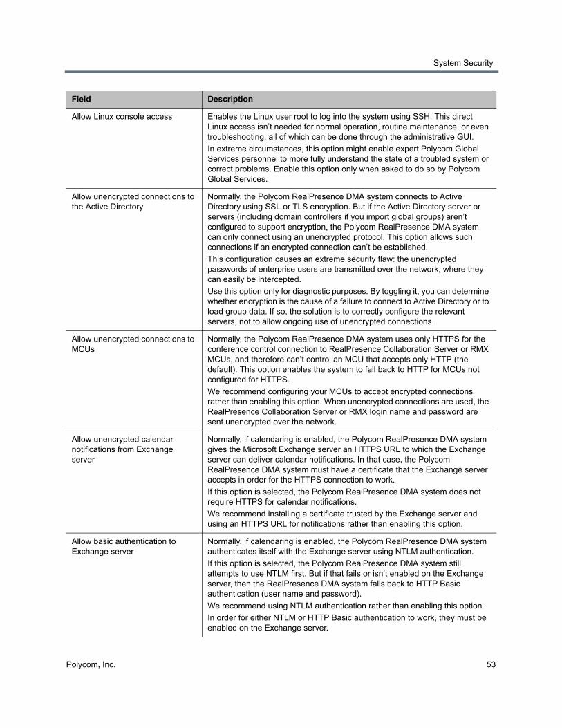
System Security
Polycom, Inc. 53
Allow Linux console access Enables the Linux user root to log into the system using SSH. This direct Linux access isn’t needed for normal operation, routine maintenance, or even troubleshooting, all of which can be done through the administrative GUI.
In extreme circumstances, this option might enable expert Polycom Global Services personnel to more fully understand the state of a troubled system or correct problems. Enable this option only when asked to do so by Polycom Global Services.
Allow unencrypted connections to the Active Directory
Normally, the Polycom RealPresence DMA system connects to Active Directory using SSL or TLS encryption. But if the Active Directory server or servers (including domain controllers if you import global groups) aren’t configured to support encryption, the Polycom RealPresence DMA system can only connect using an unencrypted protocol. This option allows such connections if an encrypted connection can’t be established.
This configuration causes an extreme security flaw: the unencrypted passwords of enterprise users are transmitted over the network, where they can easily be intercepted.
Use this option only for diagnostic purposes. By toggling it, you can determine whether encryption is the cause of a failure to connect to Active Directory or to load group data. If so, the solution is to correctly configure the relevant servers, not to allow ongoing use of unencrypted connections.
Allow unencrypted connections to MCUs
Normally, the Polycom RealPresence DMA system uses only HTTPS for the conference control connection to RealPresence Collaboration Server or RMX MCUs, and therefore can’t control an MCU that accepts only HTTP (the default). This option enables the system to fall back to HTTP for MCUs not configured for HTTPS.
We recommend configuring your MCUs to accept encrypted connections rather than enabling this option. When unencrypted connections are used, the RealPresence Collaboration Server or RMX login name and password are sent unencrypted over the network.
Allow unencrypted calendar notifications from Exchange server
Normally, if calendaring is enabled, the Polycom RealPresence DMA system gives the Microsoft Exchange server an HTTPS URL to which the Exchange server can deliver calendar notifications. In that case, the Polycom RealPresence DMA system must have a certificate that the Exchange server accepts in order for the HTTPS connection to work.
If this option is selected, the Polycom RealPresence DMA system does not require HTTPS for calendar notifications.
We recommend installing a certificate trusted by the Exchange server and using an HTTPS URL for notifications rather than enabling this option.
Allow basic authentication to Exchange server
Normally, if calendaring is enabled, the Polycom RealPresence DMA system authenticates itself with the Exchange server using NTLM authentication.
If this option is selected, the Polycom RealPresence DMA system still attempts to use NTLM first. But if that fails or isn’t enabled on the Exchange server, then the RealPresence DMA system falls back to HTTP Basic authentication (user name and password).
We recommend using NTLM authentication rather than enabling this option.
In order for either NTLM or HTTP Basic authentication to work, they must be enabled on the Exchange server.
Field Description

System Security
Polycom, Inc. 54
Skip validation of certificates received while making outbound connections
Normally, when the Polycom RealPresence DMA system connects to a server, it validates that server’s certificate.
This option configures the system to accept any certificate presented to it without validating it.
We recommend using valid certificates for all servers that the system may need to contact rather than enabling this option. Depending on system configuration, this may include:
MCUs Active Directory Exchange RealPresence Resource Manager system Other RealPresence DMA systemsEndpoints
Note: Either the Common Name (CN) or Subject Alternate Name (SAN) field of the server’s certificate must contain the address or host name specified for the server in the Polycom RealPresence DMA system.
Polycom MCUs don't include their management IP address in the SAN field of the CSR (Certificate Signing Request), so their certificates identify them only by the CN. Therefore, in the Polycom RealPresence DMA system, a Polycom MCU's management interface must be identified by the name specified in the CN field (usually the FQDN), not by IP address.
Similarly, an Active Directory server certificate often specifies only the FQDN. So in the Polycom RealPresence DMA system, identify the enterprise directory by FQDN, not by IP address.
Unlock SIP Settings mutual authentication option on the Signaling Settings page
Normally, during encrypted call signaling (SIP over TLS), the Polycom RealPresence DMA system requires the remote party (endpoint or MCU) to present a valid certificate. This is known as mutual TLS.
When enabled, this check box unlocks the Require mutual authentication (validation of client certificates) option for SIP signaling on the Signaling Settings page, allowing you to disable the mutual TLS requirement for SIP signaling.
Polycom recommends installing valid certificates on your endpoints and MCUs rather than enabling this option.
Allow non-conference participants to receive conference events
The SIP SUBSCRIBE/NOTIFY conference notification service (as described in RFCs 3265 and 4575), allows SIP devices to subscribe to a conference and receive conference rosters and notifications of conference events. Normally, the subscribing endpoints are conference participants.
This option configures the system to let devices subscribe to a conference without being participants in the conference.
Note: A subscription to a conference by a non-participant consumes a call license. Call history doesn’t include data for non-participant subscriptions.
Field Description
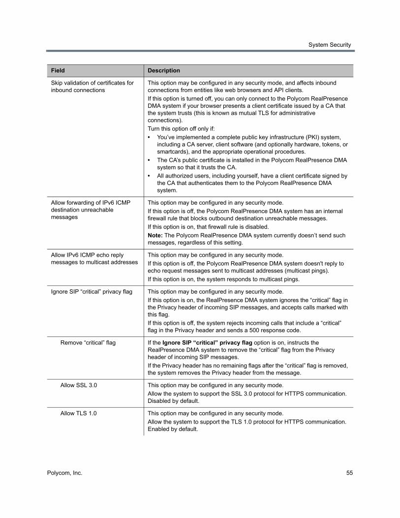
System Security
Polycom, Inc. 55
Skip validation of certificates for inbound connections
This option may be configured in any security mode, and affects inbound connections from entities like web browsers and API clients.
If this option is turned off, you can only connect to the Polycom RealPresence DMA system if your browser presents a client certificate issued by a CA that the system trusts (this is known as mutual TLS for administrative connections).
Turn this option off only if:
• You’ve implemented a complete public key infrastructure (PKI) system, including a CA server, client software (and optionally hardware, tokens, or smartcards), and the appropriate operational procedures.
• The CA’s public certificate is installed in the Polycom RealPresence DMA system so that it trusts the CA.
• All authorized users, including yourself, have a client certificate signed by the CA that authenticates them to the Polycom RealPresence DMA system.
Allow forwarding of IPv6 ICMP destination unreachable messages
This option may be configured in any security mode.
If this option is off, the Polycom RealPresence DMA system has an internal firewall rule that blocks outbound destination unreachable messages.
If this option is on, that firewall rule is disabled.
Note: The Polycom RealPresence DMA system currently doesn’t send such messages, regardless of this setting.
Allow IPv6 ICMP echo reply messages to multicast addresses
This option may be configured in any security mode.
If this option is off, the Polycom RealPresence DMA system doesn't reply to echo request messages sent to multicast addresses (multicast pings).
If this option is on, the system responds to multicast pings.
Ignore SIP “critical” privacy flag This option may be configured in any security mode.
If this option is on, the RealPresence DMA system ignores the “critical” flag in the Privacy header of incoming SIP messages, and accepts calls marked with this flag.
If this option is off, the system rejects incoming calls that include a “critical” flag in the Privacy header and sends a 500 response code.
Remove “critical” flag If the Ignore SIP “critical” privacy flag option is on, instructs the RealPresence DMA system to remove the “critical” flag from the Privacy header of incoming SIP messages.
If the Privacy header has no remaining flags after the “critical” flag is removed, the system removes the Privacy header from the message.
Allow SSL 3.0 This option may be configured in any security mode.
Allow the system to support the SSL 3.0 protocol for HTTPS communication. Disabled by default.
Allow TLS 1.0 This option may be configured in any security mode.
Allow the system to support the TLS 1.0 protocol for HTTPS communication. Enabled by default.
Field Description
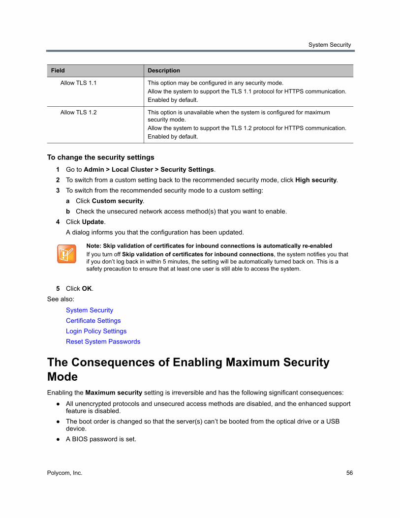
System Security
Polycom, Inc. 56
To change the security settings
1 Go to Admin > Local Cluster > Security Settings.
2 To switch from a custom setting back to the recommended security mode, click High security.
3 To switch from the recommended security mode to a custom setting:
a Click Custom security.
b Check the unsecured network access method(s) that you want to enable.
4 Click Update.
A dialog informs you that the configuration has been updated.
5 Click OK.
See also:
System Security
Certificate Settings
Login Policy Settings
Reset System Passwords
The Consequences of Enabling Maximum Security Mode Enabling the Maximum security setting is irreversible and has the following significant consequences:
● All unencrypted protocols and unsecured access methods are disabled, and the enhanced support feature is disabled.
● The boot order is changed so that the server(s) can’t be booted from the optical drive or a USB device.
● A BIOS password is set.
Allow TLS 1.1 This option may be configured in any security mode.
Allow the system to support the TLS 1.1 protocol for HTTPS communication.
Enabled by default.
Allow TLS 1.2 This option is unavailable when the system is configured for maximum security mode.
Allow the system to support the TLS 1.2 protocol for HTTPS communication.
Enabled by default.
Note: Skip validation of certificates for inbound connections is automatically re-enabled
If you turn off Skip validation of certificates for inbound connections, the system notifies you that if you don’t log back in within 5 minutes, the setting will be automatically turned back on. This is a safety precaution to ensure that at least one user is still able to access the system.
Field Description
System Security
Polycom, Inc. 57
● The port 443 redirect is removed, and the system can only be accessed by the full URL (https://<IP>:8443/dma7000, where <IP> is one of the system's management IP addresses or a host name that resolves to one of those IP addresses).
● For all server-to-server connections, the system requires the remote party to present a valid X.509 certificate. Either the Common Name (CN) or Subject Alternate Name (SAN) field of that certificate must contain the address or host name specified for the server in the Polycom RealPresence DMA system.
Polycom RMX MCUs don’t include their management IP address in the SAN field of the CSR (Certificate Signing Request), so their certificates identify them only by the CN. Therefore, in the Polycom RealPresence DMA system, an RMX MCU's management interface must be identified by the host name or FQDN specified in the CN field, not by IP address.
Similarly, an Active Directory server certificate often specifies only the FQDN. Therefore, in the Polycom RealPresence DMA system, the Active Directory must be identified by FQDN, not by IP address.
● Superclustering is not supported.
● The Polycom RealPresence DMA system can’t be integrated with Microsoft Exchange Server and doesn’t support virtual meeting rooms (VMRs) created by the Polycom Conferencing Add-in for Microsoft Outlook.
● Integration with a Polycom RealPresence Resource Manager system is not supported.
● On the Banner page, Enable login banner is selected and can’t be disabled.
● On the Login Sessions page, the Terminate Session action is not available.
● On the Troubleshooting Utilities menu, Top is removed.
● In the Add User and Edit User dialogs, conference and chairperson passcodes are obscured.
● After Maximum security is enabled, management interface users must change their passwords.
● If the system is not integrated with Active Directory, each local user can have only one assigned role (Administrator, Provisioner, or Auditor).
If some local users have multiple roles when you enable Maximum security, they retain only the highest-ranking role (Administrator > Auditor > Provisioner).
● If the system is integrated with Microsoft Active Directory, only one local user can have the Administrator role, and no local users can have the Provisioner or Auditor role.
If there are multiple local administrators when you enable Maximum security, the system prompts you to choose one local user to retain the Administrator role. All other local users, if any, become conferencing users only and can’t log into the management interface.
Each enterprise user can have only one assigned role (Administrator, Provisioner, or Auditor). If some enterprise users have multiple roles (or inherit multiple roles from their group memberships), they retain only the lowest-ranking role (Administrator > Auditor > Provisioner).
● Local user passwords have stricter limits and constraints (each is set to the noted default if below that level when you enable Maximum security):
Minimum length is 15-30 characters (default is 15).
Must contain 1 or 2 (default is 2) of each character type: uppercase alpha, lowercase alpha, numeric, and non-alphanumeric (special).
Maximum number of consecutive repeated characters is 1-4 (default is 2).
Number of previous passwords that a user may not re-use is 8-16 (default is 10).
System Security
Polycom, Inc. 58
Minimum number of characters that must be changed from the previous password is 1-4 (default is 4).
Password may not contain the user name or its reverse.
Maximum password age is 30-180 days (default is 60).
Minimum password age is 1-30 days (default is 1).
● Other configuration settings have stricter limits and constraints (each is set to the noted default if below that level when you enable Maximum security):
Session configuration limits:
Sessions per system is 4-80 (default is 40).
Sessions per user is 1-10 (default is 5).
Session timeout is 5-60 minutes (default is 10).
Local account configuration limits:
Local user account is locked after 2-10 failed logins (default is 3) due to invalid password within 1-24 hours (default is 1).
Locked account remains locked either until unlocked by an administrator (the default) or for a duration of 1-480 minutes.
● Non-conference participants can’t be permitted to register for conference events.
● Software build information is not displayed anywhere in the interface.
● You can’t restore a backup made before Maximum security was enabled.
● The RealPresence DMA system, Virtual Edition, does not support Maximum Security Mode.
● If you’re using the Mozilla Firefox browser, you need to configure it to support TLS version 1.1 so that it can function correctly with a RealPresence DMA system configured for Maximum Security Mode.
● File uploads may fail when using the Mozilla Firefox browser unless the proper steps have been taken. See below.
Enabling File Uploads in Maximum Security with Mozilla Firefox The Mozilla Firefox browser uses its own certificate database instead of the certificate database of the OS. If you use only that browser to access the Polycom RealPresence DMA system, the certificate(s) needed to securely connect to the system may be only in the Firefox certificate database and not in the Windows certificate store. This causes a problem for file uploads.
File upload via the Polycom RealPresence DMA system’s Flash-based interface bypasses the browser and creates the TLS/SSL connection itself. Because of that, it uses the Windows certificate store, not the Firefox certificate database. If the certificate(s) establishing trust aren’t there, the file upload silently fails.
To avoid this problem, you must import the needed certificates into Internet Explorer (and thus into the Windows certificate store). And, when accessing the system with Firefox, you must use its fully qualified host name.
First, start Internet Explorer and point it to the Polycom RealPresence DMA system. If you don’t receive a security warning, the needed certificates are already in the Windows certificate store.
If you receive a warning, import the needed certificates. The details for doing so depend on the version of Internet Explorer and on your enterprise’s implementation of certificates. In Internet Explorer 7, elect to continue to the site. Then click Certificate Error to the right of the address bar and click View Certificates to open the Certificate dialog. From there, you can access the Certificate Import Wizard.
System Security
Polycom, Inc. 59
The entire trust chain must be imported (the system’s signed certificate, intermediate certificates, if any, and the root CA’s certificate). When importing a certificate, let Internet Explorer automatically select a certificate store.
See also:
System Security
Security Certificates Overview
Certificate Settings
Security Settings
Reset System Passwords
Login Policy Settings The following pages, under Admin > Login Policy Settings, let you configure various aspects of user access to the system:
● Local Password
● Session
● Local User Account
● Banner
● Access Policy Settings
See also:
System Security
Certificate Settings
Security Settings
Reset System Passwords
Local Password The Local Password page lets you increase system security by specifying age, length, and complexity requirements for the passwords of local administrator, auditor, and provisioner users. These rules don’t apply to conferencing users’ conference and chairperson passcodes, or to Active Directory users.
The following table describes the fields on the Local Password page.
Field Description
Password Management
Maximum password age (days) Specify at what age a password expires (30-180 days).
Minimum password age (days) Specify how frequently a password can be changed (1-30 days).
Minimum length Specify the number of characters a password must contain (8-30).
Minimum changed characters Specify the number of characters that must be different from the previous password (1-4).
System Security
Polycom, Inc. 60
See also:
System Security
Login Policy Settings
Session The Session page lets you increase system security by limiting the number and length of login sessions.
You can see the current login sessions and terminate sessions by going to User > Login Sessions. See Login Sessions.
The following table describes the fields on the Session page.
See also:
System Security
Login Policy Settings
Reject previous passwords Specify how many of the user’s previous passwords the system remembers and won’t permit to be reused (8-30).
Password Complexity
Allow user name or its reverse form
Turns off the protection against a password containing the user’s login name or its reverse.
Lowercase letters Specify the number of lowercase letters (a-z) that a password must contain.
Uppercase letters Specify the number of uppercase letters (A-Z) that a password must contain.
Numbers Specify the number of digit characters (0-9) that a password must contain.
Special characters Specify the number of non-alphanumeric keyboard characters that a password must contain.
Maximum consecutive repeated characters
Specify how many sequential characters may be the same.
Field Description
Active system sessions Specify the number of simultaneous login sessions by all users or select Unlimited.
Note: If this limit is reached, but none of the logged-in users is an Administrator, the first Administrator user to arrive is granted access, and the system terminates the non-Administrator session that’s been idle the longest.
Active sessions per user Specify the number of simultaneous login sessions per user ID or select Unlimited.
Session timeout (minutes) Specify the length of time after which the system terminates a session for inactivity or select Unlimited.
Field Description
System Security
Polycom, Inc. 61
Local User Account The Local User Account page lets you increase system security by:
● Locking out users who have exceeded the specified number and frequency of login failures. The system locks the account either indefinitely or for the length of time you specify.
● Disabling accounts that have been inactive a specified number of days.
The following table describes the fields on the Local User Account page.
See also:
System Security
Login Policy Settings
Banner A login banner is a message that appears when users attempt to access the system. They must acknowledge the message before they can log in.
The Banner page lets you enable the banner and select or create the message it displays. The message may contain up to 1500 characters. If the system is in Maximum Security mode, the login banner is enabled and can’t be disabled.
The following table describes the fields on the Banner page.
Field Description
Account Lockout
Enable account lockout Turns on lockout feature and enables lockout configuration fields below.
Failed login threshold Specify how many consecutive login failures cause the system to lock an account.
Failed login window (hours) Specify the time span within which the consecutive failures must occur in order to lock the account.
Customize user account lockout duration (minutes)
If selected, specify how long the user’s account remains locked.
If not selected, the lockout is indefinite, and a user with a locked account must contact an Administrator to unlock it.
Account Inactivity
Customize account inactivity threshold (days)
Turns on disabling of inactive accounts and lets you specify the inactivity threshold that triggers disabling.

System Security
Polycom, Inc. 62
See also:
System Security
Login Policy Settings
Access Policy Settings The Access Policy Settings page lets you increase system security by restricting access to the management and operations interface and APIs (port 8443) and to SNMP (by default, port 161) to a whitelist of authorized IP addresses or address ranges.
If enabled, the whitelist restrictions take effect as soon as the update operation is completed. If you enable the whitelist and click Update while logged in from an IP address that’s not included in the whitelist, the system warns you that you won’t be able to access the system and asks you to confirm the update.
The whitelist settings apply to all clusters in a supercluster. When you join a cluster to a supercluster, the cluster’s settings are replaced by those from the supercluster.
The following table describes the fields on the Access Policy Settings page.
Field Description
Enable login banner Enables the display of a login banner.
If this box is unchecked, the Message field is disabled. The existing contents, if any, remain unchanged, but aren’t displayed to users.
Message Select one of the messages from the list, or select Custom and type or paste your own message into the field below.
If you select one of the built-in samples, it’s copied into the Message field, and you can then edit the copy. When you do so, the system resets the list to Custom.
Your edits don’t affect the stored sample. You can revert to the original version of the sample by re-selecting it from the list.
Field Description
Accept management connections from these IP addresses and address ranges on ports 8443 (GUI/API) and 161 (SNMP)
Enables the input field below and restricts management access to the IP addresses or address ranges added to the list.
If this box is unchecked, the list and input field are disabled. The existing contents of the list, if any, remain unchanged so that it can be re-enabled at any time without having to re-enter the addresses.
Note: The label changes to reflect the currently configured SNMP port (see Configure SNMP). Port 161 is the default.
(list) Lists the IP addresses and address ranges authorized for management access. Select an entry and click Delete to remove it from the list.
(input field) Enter an IP address or address range and click Add. Enter a range as valid starting and ending IP addresses separated by a dash. For example:
(IPv4) 10.33.33.0 - 10.33.34.255
(IPv6) ::1:fffe - ::2:1
System Security
Polycom, Inc. 63
See also:
System Security
Security Settings
The Consequences of Enabling Maximum Security Mode
Login Policy Settings
Reset System Passwords
Reset System Passwords In an extremely high-security environment, security compliance policies may require that all passwords be changed at certain intervals, including operating system passwords.
The Reset System Passwords page is available only if the system is in maximum security mode. It lets you change these operating system passwords (such as the password for grub) to new, randomly-generated values. These are passwords for logins that aren’t possible on a secure system. Resetting these operating system passwords has no effect on authorized users of the management interface (Administrators, Auditors, and Provisioners) or conferencing users.
To reset system passwords
1 Make sure there are no calls or conferences on the system.
2 Go to Admin > Local Cluster > Reset System Passwords.
3 Click Reset Passwords.
The system warns you that active calls and conferences will be terminated and the system will restart, and asks you to confirm.
4 Click Yes.
The system informs you that the passwords have been reset and that you’re being logged out. Then it restarts. This takes several minutes.
5 Wait a few minutes to log back in.
See also:
System Security
Security Settings
The Consequences of Enabling Maximum Security Mode
Login Policy Settings
Access Policy Settings
Polycom, Inc. 64
Local Cluster Configuration
This section describes the following Polycom® RealPresence® Distributed Media Application™ (DMA®) 7000 system configuration topics:
● Network Settings
● Time Settings
● Licenses
● Signaling Settings
● Alerting Settings
● Configure Logging Settings
● Configure Remote Backup Settings
● Automatically Send Usage Data
These are cluster-specific settings that are not part of the data store shared across superclustered systems. See Introduction to the Polycom RealPresence DMA System.
If you’re performing the initial configuration of your Polycom RealPresence DMA system, study Polycom RealPresence DMA System Initial Configuration Summary before you continue.
Network SettingsThe following table describes the fields on the Network Settings page. In the Appliance Edition, most of these values are normally set in the USB Configuration Utility during system installation and rarely need to be changed. In the Virtual Edition, some of these settings are provisioned automatically when the system is deployed with RealPresence Platform Director. See the Getting Started Guide and the Getting Started Guide for a Virtual Environment.
Local Cluster Configuration
Polycom, Inc. 65
Caution: Network settings changes require a restart
Changing some network settings (host names, IP addresses, or domains) requires a system restart and terminates all active conferences.
If the system is using a CA-provided identity certificate, changing some network settings (host names or IP addresses) also requires you to update the certificate. (If the system is using a self-signed certificate, an updated one is automatically created.)
You can’t change these network settings while the system is part of a supercluster or integrated with a Polycom RealPresence Resource Manager system. You must first leave the supercluster or terminate the integration. If the cluster is responsible for any territories (as primary or backup), reassign those territories. After the change, rejoin the supercluster or Polycom RealPresence Resource Manager system. See Superclustering or RealPresence Resource Manager Integration.
Incorrect network information may make the system unusable and the management interface unreachable.
Caution: Configuring the RealPresence DMA system in a secure environment
The 802.1x LAN security settings can’t be configured in the USB Configuration Utility. In a highly secure network that requires 802.1x authentication, the Polycom RealPresence DMA system won’t be accessible until those settings are properly configured. To do so, follow the procedure for configuring the network settings using a laptop, as described in the Deployment Guide for Maximum Security Environments.
Note: Virtual host name not needed for single-server systems
This version of the Polycom RealPresence DMA system eliminates the need for virtual host name(s) and IP addresses in a single-server system or cluster. When a version 5.0 or earlier single-server RealPresence DMA system is upgraded to version 5.1 or later, the previous version's virtual host name(s) and IP addresses become the upgraded version's physical host name(s) and IP addresses, so accessing the system doesn't change.
(Exception: If only IPv6 is enabled, the system must have two addresses, so a single-server system must still have a virtual host name and IP address.)
Field Description
System IP type IP addressing supported (IPv4, IPv6, or both).
System server configuration Number of servers (1 or 2) in this cluster.
Caution: Once this is set to 2 server configuration, it can’t be changed back to 1 server configuration. To reconfigure a two-server system as two separate single-server systems, you must use the USB Configuration Utility. See the Polycom RealPresence DMA 7000 System Getting Started Guide.
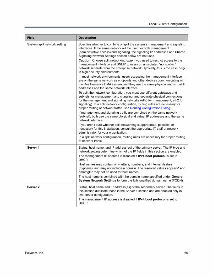
Local Cluster Configuration
Polycom, Inc. 66
System split network setting Specifies whether to combine or split the system’s management and signaling interfaces. If the same network will be used for both management (administrative access) and signaling, the signaling IP addresses and Shared Signaling Network Settings section below are not used.
Caution: Choose split networking only if you need to restrict access to the management interface and SNMP to users on an isolated “non-public” network separate from the enterprise network. Typically, this is the case only in high-security environments.
In most network environments, users accessing the management interface are on the same network as endpoints and other devices communicating with the RealPresence DMA system, and they use the same physical and virtual IP addresses and the same network interface.
To split the network configuration, you must use different gateways and subnets for management and signaling, and separate physical connections for the management and signaling networks (eth0 for management, eth2 for signaling). In a split network configuration, routing rules are necessary for proper routing of network traffic. See Routing Configuration Dialog.
If management and signaling traffic are combined on the same network (subnet), both use the same physical and virtual IP addresses and the same network interface.
If you aren’t sure whether split networking is appropriate, possible, or necessary for this installation, consult the appropriate IT staff or network administrator for your organization.
In a split network configuration, routing rules are necessary for proper routing of network traffic.
Server 1 Status, host name, and IP address(es) of the primary server. The IP type and network setting determine which of the IP fields in this section are enabled.
The management IP address is disabled if IPv4 boot protocol is set to DHCP.
Host names may contain only letters, numbers, and internal dashes (hyphens), and may not include a domain. The reserved values appserv* and dmamgk-* may not be used for host names.
The host name is combined with the domain name specified under General System Network Settings to form the fully qualified domain name (FQDN).
Server 2 Status, host name and IP address(es) of the secondary server. The fields in this section duplicate those in the Server 1 section and are enabled only in two-server configuration.
The management IP address is disabled if IPv4 boot protocol is set to DHCP.
Field Description
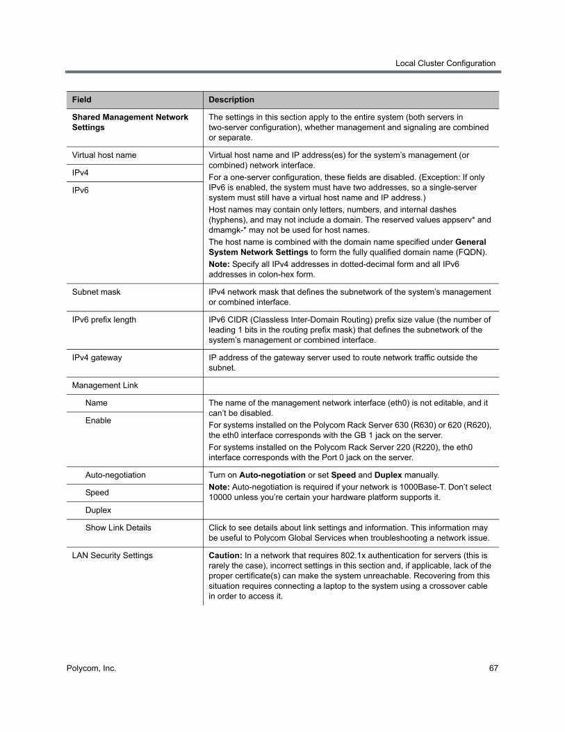
Local Cluster Configuration
Polycom, Inc. 67
Shared Management Network Settings
The settings in this section apply to the entire system (both servers in two-server configuration), whether management and signaling are combined or separate.
Virtual host name Virtual host name and IP address(es) for the system’s management (or combined) network interface.
For a one-server configuration, these fields are disabled. (Exception: If only IPv6 is enabled, the system must have two addresses, so a single-server system must still have a virtual host name and IP address.)
Host names may contain only letters, numbers, and internal dashes (hyphens), and may not include a domain. The reserved values appserv* and dmamgk-* may not be used for host names.
The host name is combined with the domain name specified under General System Network Settings to form the fully qualified domain name (FQDN).
Note: Specify all IPv4 addresses in dotted-decimal form and all IPv6 addresses in colon-hex form.
IPv4
IPv6
Subnet mask IPv4 network mask that defines the subnetwork of the system’s management or combined interface.
IPv6 prefix length IPv6 CIDR (Classless Inter-Domain Routing) prefix size value (the number of leading 1 bits in the routing prefix mask) that defines the subnetwork of the system’s management or combined interface.
IPv4 gateway IP address of the gateway server used to route network traffic outside the subnet.
Management Link
Name The name of the management network interface (eth0) is not editable, and it can’t be disabled.
For systems installed on the Polycom Rack Server 630 (R630) or 620 (R620), the eth0 interface corresponds with the GB 1 jack on the server.
For systems installed on the Polycom Rack Server 220 (R220), the eth0 interface corresponds with the Port 0 jack on the server.
Enable
Auto-negotiation Turn on Auto-negotiation or set Speed and Duplex manually.
Note: Auto-negotiation is required if your network is 1000Base-T. Don’t select 10000 unless you’re certain your hardware platform supports it.
Speed
Duplex
Show Link Details Click to see details about link settings and information. This information may be useful to Polycom Global Services when troubleshooting a network issue.
LAN Security Settings Caution: In a network that requires 802.1x authentication for servers (this is rarely the case), incorrect settings in this section and, if applicable, lack of the proper certificate(s) can make the system unreachable. Recovering from this situation requires connecting a laptop to the system using a crossover cable in order to access it.
Field Description
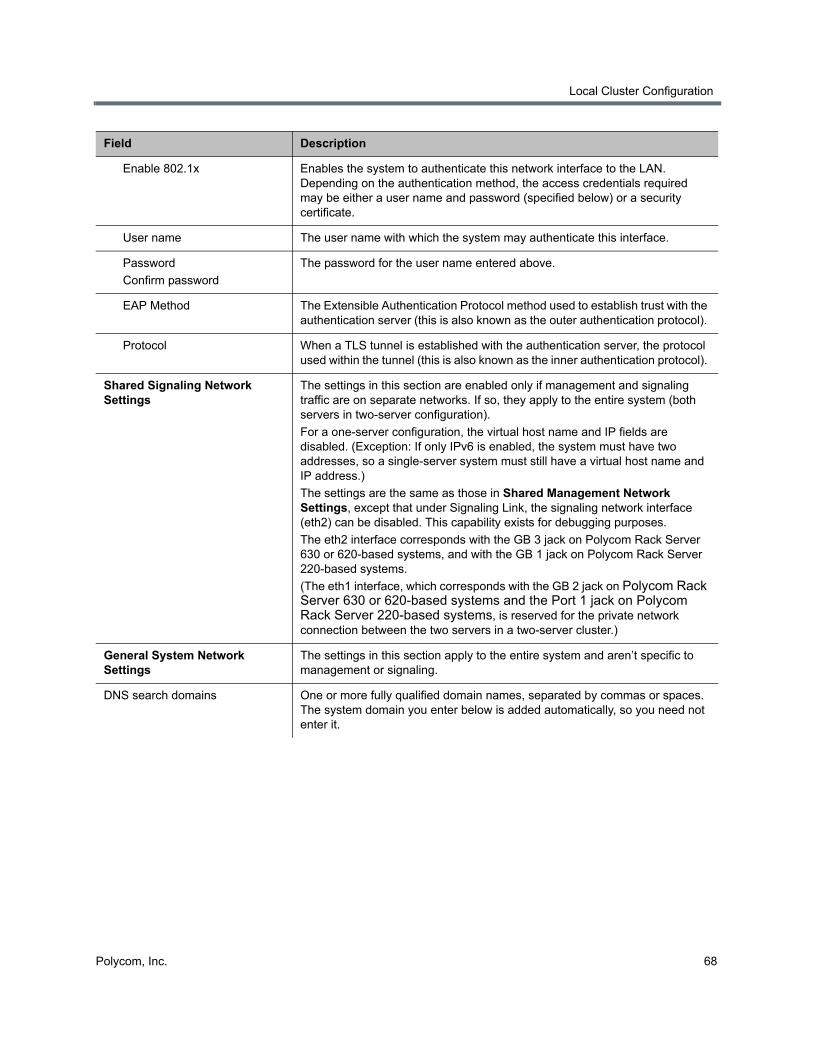
Local Cluster Configuration
Polycom, Inc. 68
Enable 802.1x Enables the system to authenticate this network interface to the LAN. Depending on the authentication method, the access credentials required may be either a user name and password (specified below) or a security certificate.
User name The user name with which the system may authenticate this interface.
Password
Confirm password
The password for the user name entered above.
EAP Method The Extensible Authentication Protocol method used to establish trust with the authentication server (this is also known as the outer authentication protocol).
Protocol When a TLS tunnel is established with the authentication server, the protocol used within the tunnel (this is also known as the inner authentication protocol).
Shared Signaling Network Settings
The settings in this section are enabled only if management and signaling traffic are on separate networks. If so, they apply to the entire system (both servers in two-server configuration).
For a one-server configuration, the virtual host name and IP fields are disabled. (Exception: If only IPv6 is enabled, the system must have two addresses, so a single-server system must still have a virtual host name and IP address.)
The settings are the same as those in Shared Management Network Settings, except that under Signaling Link, the signaling network interface (eth2) can be disabled. This capability exists for debugging purposes.
The eth2 interface corresponds with the GB 3 jack on Polycom Rack Server 630 or 620-based systems, and with the GB 1 jack on Polycom Rack Server 220-based systems.
(The eth1 interface, which corresponds with the GB 2 jack on Polycom Rack Server 630 or 620-based systems and the Port 1 jack on Polycom Rack Server 220-based systems, is reserved for the private network connection between the two servers in a two-server cluster.)
General System Network Settings
The settings in this section apply to the entire system and aren’t specific to management or signaling.
DNS search domains One or more fully qualified domain names, separated by commas or spaces. The system domain you enter below is added automatically, so you need not enter it.
Field Description
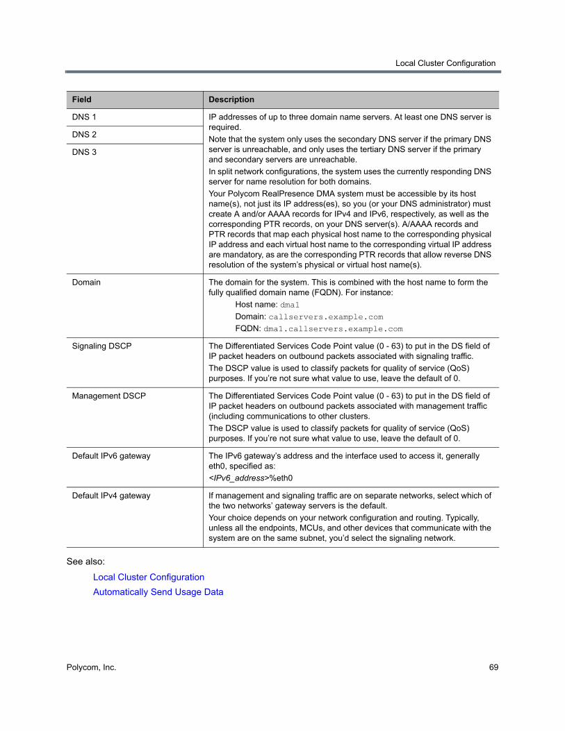
Local Cluster Configuration
Polycom, Inc. 69
See also:
Local Cluster Configuration
Automatically Send Usage Data
DNS 1 IP addresses of up to three domain name servers. At least one DNS server is required.
Note that the system only uses the secondary DNS server if the primary DNS server is unreachable, and only uses the tertiary DNS server if the primary and secondary servers are unreachable.
In split network configurations, the system uses the currently responding DNS server for name resolution for both domains.
Your Polycom RealPresence DMA system must be accessible by its host name(s), not just its IP address(es), so you (or your DNS administrator) must create A and/or AAAA records for IPv4 and IPv6, respectively, as well as the corresponding PTR records, on your DNS server(s). A/AAAA records and PTR records that map each physical host name to the corresponding physical IP address and each virtual host name to the corresponding virtual IP address are mandatory, as are the corresponding PTR records that allow reverse DNS resolution of the system’s physical or virtual host name(s).
DNS 2
DNS 3
Domain The domain for the system. This is combined with the host name to form the fully qualified domain name (FQDN). For instance:
Host name: dma1
Domain: callservers.example.com
FQDN: dma1.callservers.example.com
Signaling DSCP The Differentiated Services Code Point value (0 - 63) to put in the DS field of IP packet headers on outbound packets associated with signaling traffic.
The DSCP value is used to classify packets for quality of service (QoS) purposes. If you’re not sure what value to use, leave the default of 0.
Management DSCP The Differentiated Services Code Point value (0 - 63) to put in the DS field of IP packet headers on outbound packets associated with management traffic (including communications to other clusters.
The DSCP value is used to classify packets for quality of service (QoS) purposes. If you’re not sure what value to use, leave the default of 0.
Default IPv6 gateway The IPv6 gateway’s address and the interface used to access it, generally eth0, specified as:
<IPv6_address>%eth0
Default IPv4 gateway If management and signaling traffic are on separate networks, select which of the two networks’ gateway servers is the default.
Your choice depends on your network configuration and routing. Typically, unless all the endpoints, MCUs, and other devices that communicate with the system are on the same subnet, you’d select the signaling network.
Field Description
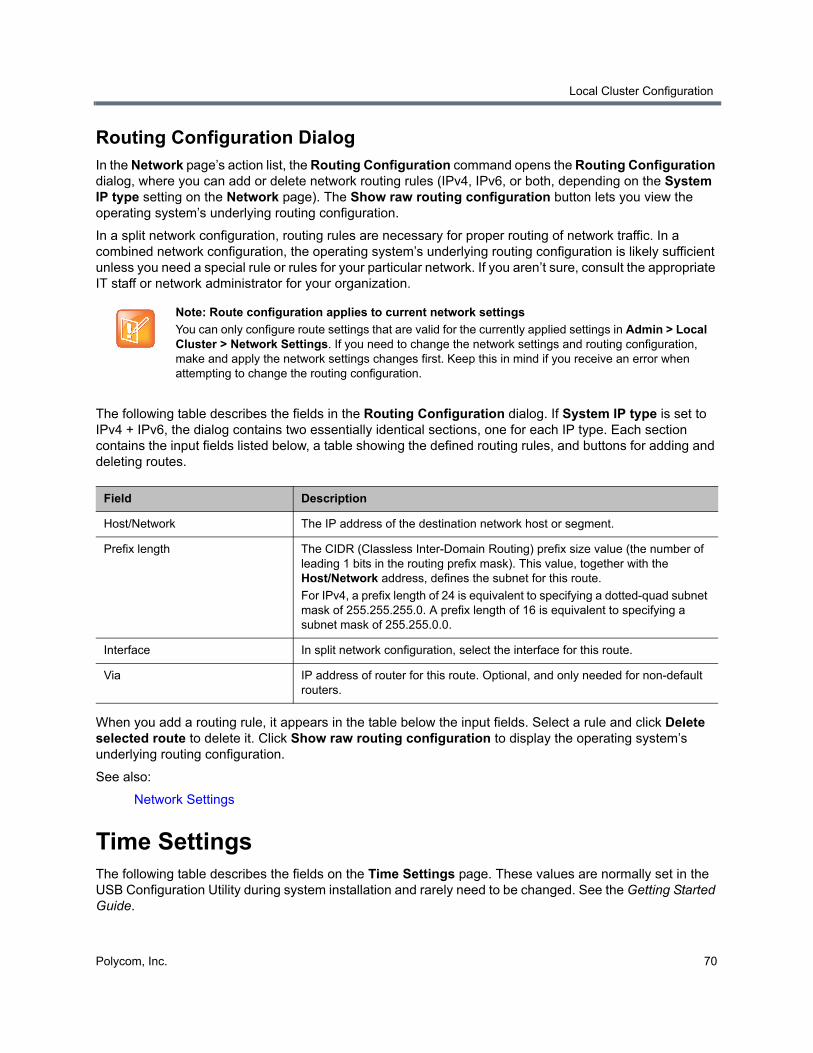
Local Cluster Configuration
Polycom, Inc. 70
Routing Configuration DialogIn the Network page’s action list, the Routing Configuration command opens the Routing Configuration dialog, where you can add or delete network routing rules (IPv4, IPv6, or both, depending on the System IP type setting on the Network page). The Show raw routing configuration button lets you view the operating system’s underlying routing configuration.
In a split network configuration, routing rules are necessary for proper routing of network traffic. In a combined network configuration, the operating system’s underlying routing configuration is likely sufficient unless you need a special rule or rules for your particular network. If you aren’t sure, consult the appropriate IT staff or network administrator for your organization.
The following table describes the fields in the Routing Configuration dialog. If System IP type is set to IPv4 + IPv6, the dialog contains two essentially identical sections, one for each IP type. Each section contains the input fields listed below, a table showing the defined routing rules, and buttons for adding and deleting routes.
When you add a routing rule, it appears in the table below the input fields. Select a rule and click Delete selected route to delete it. Click Show raw routing configuration to display the operating system’s underlying routing configuration.
See also:
Network Settings
Time SettingsThe following table describes the fields on the Time Settings page. These values are normally set in the USB Configuration Utility during system installation and rarely need to be changed. See the Getting Started Guide.
Note: Route configuration applies to current network settings
You can only configure route settings that are valid for the currently applied settings in Admin > Local Cluster > Network Settings. If you need to change the network settings and routing configuration, make and apply the network settings changes first. Keep this in mind if you receive an error when attempting to change the routing configuration.
Field Description
Host/Network The IP address of the destination network host or segment.
Prefix length The CIDR (Classless Inter-Domain Routing) prefix size value (the number of leading 1 bits in the routing prefix mask). This value, together with the Host/Network address, defines the subnet for this route.
For IPv4, a prefix length of 24 is equivalent to specifying a dotted-quad subnet mask of 255.255.255.0. A prefix length of 16 is equivalent to specifying a subnet mask of 255.255.0.0.
Interface In split network configuration, select the interface for this route.
Via IP address of router for this route. Optional, and only needed for non-default routers.
Local Cluster Configuration
Polycom, Inc. 71
See also:
Local Cluster Configuration
Automatically Send Usage Data
LicensesThe Polycom RealPresence DMA system is licensed for the number of concurrent calls it can handle and optionally for API access. See License the Polycom RealPresence DMA System for more information about licensing.
Licenses for the Appliance EditionThe following table describes the fields on the Licenses page when using the Appliance Edition of the RealPresence DMA system.
Caution: Time settings changes require a restart
Changing time settings requires a system restart and terminates all active conferences.
You can’t change the system’s time settings while it’s integrated with a Polycom RealPresence Resource Manager system or part of a supercluster. The integration must first be terminated or the cluster removed from the supercluster. See RealPresence Resource Manager Integration or Superclustering.
We strongly recommend specifying NTP servers.
Field Description
System time zone Time zone in which the system is located. We strongly recommend selecting the time zone of a specific geographic location (such as America/Denver), not one of the generic GMT offsets (such as GMT+07 POSIX).
If you really want to use a generic GMT offset (for instance, to prevent automatic daylight saving time adjustments), note that they use the Linux/Posix convention of specifying how many hours ahead of or behind local time GMT is. Thus, the generic equivalent of America/Denver (UTC-07:00) is GMT+07, not GMT-07.
Manually set system time We don’t recommend setting time and date manually.
NTP Servers Specify up to three time servers for maintaining system time (we recommend three). Enter IP addresses or fully qualified domain names.
Field Description
Active License
Licensed calls The maximum number of concurrent calls that the license enables.
Local Cluster Configuration
Polycom, Inc. 72
Licenses for the Virtual EditionThe following table describes the fields on the Licenses page when using the Virtual Edition of the RealPresence DMA system.
Licensed capabilities Currently, the only separately licensed capability is access to the RealPresence Platform API.
Note: An API license isn't required in order for a Polycom RealPresence Resource Manager system to access the API. It's only needed for a client application you or a third party develop.
Licensed capabilities The special features of the Polycom RealPresence DMA system that the license enables.
Activation Keys
A two-server cluster has two sets of the fields below, one for each server in the cluster.
System serial number The serial number of the specified server.
Activation key The activation key you received from Polycom for this server. The key for each server must be the correct one for that server’s serial number.
End User License Agreement
Status The state of acceptance of the EULA; if not accepted, this system is unable to make calls.
User The user who accepted the EULA.
Date accepted The GMT date and time of EULA acceptance.
Automatically send usage data Select to help improve this product by sending anonymous usage data to Polycom.
See Automatically Send Usage Data for more information.
Field Description
Active License
Licensed calls The maximum number of concurrent calls that the license enables.
Licensed capabilities Currently, the only separately licensed capability is access to the RealPresence Platform API.
Note: An API license isn't required in order for a Polycom RealPresence Resource Manager system to access the API. It's only needed for a client application you or a third party develop.
DMA Host
Host name The host name of this VM instance, configurable on the Admin > Local Cluster > Network Settings page.
Host ID The VMware UUID of this VM instance.
Field Description
Local Cluster Configuration
Polycom, Inc. 73
Add Licenses You can add licenses to both Appliance Edition and Virtual Edition systems.
Add Licenses to the RealPresence DMA system, Appliance Edition
Adding licenses to your Polycom RealPresence DMA system, Appliance Edition, is a two-step process:
● Request a software activation key code for each server.
● Enter the activation key codes into the system.
The procedures below describe the process.
To request a software activation key code for each server
1 Log into the Polycom RealPresence DMA system as an administrator and go to Admin > Local Cluster > Licenses.
2 Record the serial number for each Polycom RealPresence DMA server:
Server A: ____________________________
Server B: ____________________________ (none for single-server system)
3 Go to http://www.polycom.com/activation.
License version The version of the installed license.
Licensing Server
License server address The read-only address of the primary licensing server.
Note: This field is automatically provisioned by RealPresence Platform Director.
Backup server address The read-only IP address or domain name of the secondary license server.
Note: This information is automatically provisioned by RealPresence Platform Director.
Port The port used for communication with the licensing server(s). The default port is 3333.
Last successful connection The licensing server that the system last communicated with, followed by the time of the last communication.
End User License Agreement
Status The state of acceptance of the EULA; if not accepted, this system is unable to make calls.
User The user who accepted the EULA.
Date accepted The GMT date and time of EULA acceptance.
Automatically send usage data Select to help improve this product by sending anonymous usage data to Polycom.
See Automatically Send Usage Data for more information.
Field Description
Local Cluster Configuration
Polycom, Inc. 74
4 If you don’t already have one, register for an account. Then log in.
5 Select Licensing & Product Registration > Activation/Upgrade.
A product chooser dialog appears.
6 Select All other Polycom Products.
7 Select SITE & Single Activation / Upgrade.
8 In the Serial Number field, enter the first (or only) server’s serial number (which you recorded in step 2).
9 In the License Number field, enter the software license number listed on the first (or only) server’s License Certificate (shipped with the product).
10 Click Generate.
11 When the activation key for the first (or only) server appears, record it:
Server A: __________-__________-_________-___________
12 If you have a single-server Polycom RealPresence DMA system, you’re finished with this procedure. Continue to the next procedure.
13 If you have a two-server cluster, repeat steps 8–10, this time entering the second license number you received and the second server’s serial number (also recorded in step 2).
14 When the activation key for the second server appears, record it:
Server B: __________-__________-_________-___________
To enter license activation key codes
1 Go to Admin > Local Cluster > Licenses.
2 In the Activation key field for the first (or only) server, enter the activation key code that was generated for that server’s serial number.
3 If you have a two-server cluster, in the Activation key field for the second server, enter the activation key code that was generated for that server’s serial number.
4 Click Update.
A dialog informs you that the licenses have been updated.
5 Click OK.
Caution: Activation keys linked to the server serial number
An activation key is linked to a specific server’s serial number. For a two-server cluster, you must generate the activation key for each server using that server’s serial number. Licensing will fail if you generate both activation keys from the same server serial number.
Caution: Activation keys linked to the server serial number
An activation key is linked to a specific server’s serial number. Each Activation Key field is labeled with a serial number. For a two-server cluster, make sure that the activation key code you enter for each server is the correct one for that server’s serial number.
Local Cluster Configuration
Polycom, Inc. 75
Add Licenses to the RealPresence DMA system, Virtual Edition
The RealPresence DMA system, Virtual Edition, is deployed and licensed through Polycom RealPresence Platform Director. You can view the licensing information for your system from the RealPresence DMA system user interface on the Admin > Local Cluster > Licenses page.
See the RealPresence Platform Director System Administrator’s Guide for more information.
See also:
Local Cluster Configuration
Automatically Send Usage Data
Signaling SettingsOn the Signaling Settings page, you can configure H.323 and SIP signaling.
H.323, SIP, and WebRTC SignalingIf H.323 signaling is enabled, the Polycom RealPresence DMA system’s Call Server operates as a gatekeeper, receiving registration requests and calls from H.323 devices. If SIP signaling is enabled, the Call Server operates as a SIP registrar and proxy server, receiving registration requests and calls from SIP devices. If WebRTC signaling is enabled, the Call Server processes Polycom® RealPresence® Web Suite conferences initiated from WebRTC-capable Google Chrome web browsers. If more than one are enabled, the system allows devices using different protocols to communicate in multipoint conferences.
At least one of the protocols must be enabled in order for the RealPresence DMA system’s Conference Manager to receive calls for multipoint conferences and distribute them among the MCUs configured on the system.
On this page, you can also:
● Turn on H.235 authentication for H.323 devices.
● Turn on SIP digest authentication for SIP devices.
● Click a Device authentication settings link to go to the Device Authentication page, where you can configure SIP device authentication and maintain the inbound device authentication list for both H.323 and SIP devices (see Device Authentication).
Note: Local cluster not supported with virtual edition
The RealPresence DMA Virtual Edition does not support a two-server local cluster configuration. However, superclustering of individual RealPresence DMA Virtual Edition instances is fully supported in a virtual environment.
Note: Supercluster-wide signaling settings
Although these are cluster-specific settings that are not part of the data store shared across superclustered systems, we strongly recommend that all signaling settings be the same across all clusters in a supercluster.
The settings for untrusted SIP call handling (“unauthorized” or “guest” calls) must be the same across all clusters in a supercluster.
Local Cluster Configuration
Polycom, Inc. 76
● Configure specific ports or prefixes for untrusted (“unauthorized” or “guest”) SIP calls that can only access specific resources (VMRs, VEQs, or any external devices).
The RealPresence DMA System as a SIP <–> H.323 Gateway
The RealPresence DMA system can function as a gateway for point-to-point calls between SIP and H.323 devices, whether they are registered directly to the RealPresence DMA system or to an external device. The gateway function is not used for calls to virtual meeting rooms (VMRs), virtual entry queues (VEQs), external addresses, or IP addresses.
As a best practice, Polycom recommends configuring your video conferencing network in such a way as to avoid using the RealPresence DMA system as a gateway between H.323 and SIP devices.
The gateway functionality does not support the following features:
● Media encryption
● H.239 content
● DTMF transmission
H.323 Device Authentication
In an environment where H.235 authentication is used, H.323 devices include their credentials (name and password) in registration and signaling (RAS) requests. The Polycom RealPresence DMA system authenticates requests as follows:
● If it’s a signaling request (ARQ, BRQ, DRQ) from an unregistered endpoint, the Call Server doesn’t authenticate the credentials.
● Otherwise, if the request is from an endpoint and the Polycom RealPresence DMA system is integrated with a Polycom RealPresence Resource Manager system, the Call Server attempts to authenticate the endpoint’s credentials with the RealPresence Resource Manager system.
● If it can’t authenticate with the RealPresence Resource Manager system, or if the request is from an MCU or neighbor gatekeeper, the Call Server attempts to authenticate using its device authentication list.
● If it’s a signaling request from a registered endpoint, or if the request is from an MCU or neighbor gatekeeper, the Call Server attempts to authenticate using its device authentication list (see Device Authentication).
If the credentials can’t be authenticated, the Call Server rejects the registration or signaling request. For call signaling requests, it also rejects the request if the credentials differ from those with which the device registered.
SIP Device Authentication
The SIP digest authentication mechanism is described in RFC 3261, starting in section 22, and in RFC 2617, section 3. When a SIP endpoint registers with or calls the Polycom RealPresence DMA system, if the request includes authentication information, that information is checked against the Call Server’s local device authentication list (see Device Authentication).
Note: Authentication for specific devices
You can turn authentication off and on for specific devices (assuming that it’s turned on here for that device type). See Edit Device Dialog.

Local Cluster Configuration
Polycom, Inc. 77
SIP authentication can be enabled at the port/transport level or (for “unauthorized” access prefixes) the prefix level.
If SIP authentication is enabled and an endpoint’s request doesn’t include authentication information, the Call Server responds with an authentication challenge containing the required fields (see the RFCs). If the endpoint responds with valid authentication information, the system accepts the registration or call.
Untrusted SIP Call Handling Configuration
You can configure special handling for SIP calls from devices outside the corporate firewall that aren’t registered with the Polycom RealPresence DMA system and aren’t from a federated division or enterprise. These calls come to the RealPresence DMA system via SIP session border controllers (SBCs) such as a Polycom RealPresence Access Director or Acme Packet Session Border Controller device (which are configured as SIP peers in the RealPresence DMA system; see External SIP Peer).
You can route such untrusted (“unauthorized” or “guest”) calls by creating a separate set of “guest” dial rules used only for these untrusted calls. See Dial Rules.
Depending on the SIP SBC and how it’s configured, such calls can be distinguished in one of two ways:
● By port: The SBC routes untrusted calls to a specific port.
● By prefix: The SBC adds a specific prefix in the Request-URI of the first INVITE message for the call.
The RealPresence Access Director SBC supports only the prefix method. The Acme Packet Session Border Controller SBC can be configured for either.
In the SIP Settings section of the page, you can add one or more ports, prefixes, or both for untrusted calls. For each entry, you can specify whether authentication is required. Calls to an untrusted call prefix follow the authentication setting for that prefix, not for the port on which they’re received. For port entries, you can also specify the transport, and if TLS, whether certificate validation is required (mutual TLS).
WebRTC Conferencing
WebRTC participants start or enter a conference by connecting to the Polycom® RealPresence® Web Suite Experience Portal, which manages signaling between WebRTC clients and the RealPresence DMA system. The RealPresence DMA system cannot accept WebRTC calls directly from a WebRTC client.
Smaller, less complex conferences involving up to three WebRTC participants do not require an MCU. This is known as “mesh” mode. In this mode, the WebRTC media streams are passed directly from client to client. When required, the RealPresence DMA system assigns a WebRTC-capable MCU to host the conference:
● If a fourth participant joins the conference
Note: SIP device authentication
If inbound SIP authentication is turned on for a port or prefix, the Polycom RealPresence DMA system challenges any SIP message coming to the system via that port or with that prefix. Any SIP peer and other device that interacts with the system by those means must be configured to authenticate itself, or you must turn off Device authentication for that specific device. See Edit Device Dialog.
Note: Require certificate validations for TLS
If the Security Settings page option “Unlock SIP Settings mutual authentication option on the Signaling Settings page” is unchecked, then the option “Require mutual authentication (validation of client certificates)” is turned on for both authorized and unauthorized ports, and it can’t be turned off. See Security Settings.
Local Cluster Configuration
Polycom, Inc. 78
● If a non-WebRTC participant joins the conference
● If certain conference features are needed, such as conference recording
Once an MCU is assigned to host the conference, participants using WebRTC clients have the same experience as participants using SIP or H.323 endpoints. If a WebRTC client dials a conference that requires an MCU and the system selects an MCU that does not support WebRTC, the client is disconnected. For this reason, Polycom recommends creating MCU pool orders that consist only of MCUs that support WebRTC.
You can configure how the RealPresence DMA system handles conferences involving WebRTC participants by editing the conference template used for the conference (See Conference Templates).
The following limitations apply to WebRTC conferencing:
● WebRTC participants cannot enter conferences by dialing VEQs.
● WebRTC conferences do not support the SVC only conference mode.
● Many conference template settings are not compatible with the WebRTC with mesh only or WebRTC with MCUs or mesh settings. See WebRTC Conference Feature Limitations.
● WebRTC with mesh only conference templates are not supported for RealConnectTM conferences.
● Cisco Codian options are disabled when you enable WebRTC conferencing.
Signaling Settings Fields
The following table describes the fields on the Signaling Settings page.
Field Description
H.323 Settings
Enable H.323 signaling Enables the system to receive H.323 calls.
Caution: Disabling H.323 terminates any existing H.323 calls. When you click Update, the system prompts you to confirm.
Status Indicates whether the system’s H.323 gatekeeper functions are active.
H.225 port Specifies the port number the system’s gatekeeper uses for call signaling.
We recommend using the default port number (1720), but you can use the same value as the RAS port or any other value from 1024 to 65535 that’s not already in use.
RAS port Specifies the port number the system’s gatekeeper uses for RAS (Registration, Admission and Status).
We recommend using the default port number (1719), but you can use the same value as the H.225 port or any other value from 1024 to 65535 that’s not already in use.
H.245 open firewall ports Shows the port range used for H.245 so you can configure your firewall accordingly. This is display only.
H.323 multicast Enables the system to support gatekeeper discovery (GRQ messages from endpoints) as described in the H.323 and H.225.0 specifications.
Local Cluster Configuration
Polycom, Inc. 79
Enable H.323 device authentication
Check the box to turn on H.323 device authentication.
Click Device authentication settings to go to the Device Authentication page and add authentication credentials (see Device Authentication).
SIP Settings
Enable SIP signaling Enables the system to receive Session Initiation Protocol (SIP) calls.
Caution: Disabling SIP terminates any existing SIP calls. When you click Update, the system prompts you to confirm.
Enable ANAT support Configures the system to pass through Alternative Network Address Types (ANAT) signaling (RFC 4091 and RFC 4092) in the Session Description Protocol (SDP) for the purpose of negotiating IP version in a dual-stack (IPv4 + IPv6) environment.
Authorized ports
Unencrypted SIP port To permit unencrypted SIP connections, select either TCP or UDP/TCP from the list. Select None to disallow unencrypted SIP connections.
We recommend using the default port number (5060), but you can use any value from 1024 to 65535 that’s not already in use and is different from the TLS port and from any “unauthorized” or “guest” ports that your SBC(s) may be configured to use for calls to the system.
Enable authentication Check the box to turn on SIP device authentication for unencrypted SIP.
Click the Device authentication settings link to go to the Device Authentication page to configure SIP device authentication and add device authentication credentials (see Device Authentication). The settings on that page determine:
• The realm used for authentication.
• Whether the Call Server responds to unauthenticated requests with 401 (Unauthorized) or 407 (Proxy Authentication Required).
TLS port Specifies the port number the system uses for TLS.
We recommend using the default port number (5061), but you can use any value from 1024 to 65535 that’s not already in use and is different from the UDP/TCP port and from any “unauthorized” or “guest” ports that your SBC(s) may be configured to use for calls to the system.
If SIP signaling is enabled, TLS is automatically supported. Unless unencrypted SIP connections are specifically permitted, TLS must be used.
Enable authentication Check the box to turn on SIP device authentication for encrypted SIP.
Click the Device authentication settings link to go to the Device Authentication page to configure SIP device authentication and add device authentication credentials (see Device Authentication). The settings on that page determine:
• The realm used for authentication.
• Whether the Call Server responds to unauthenticated requests with 401 (Unauthorized) or 407 (Proxy Authentication Required).
Field Description
Local Cluster Configuration
Polycom, Inc. 80
See also:
Local Cluster Configuration
Automatically Send Usage Data
Add Guest Port DialogThe Add Guest Port dialog appears when you click the Add button next to the Unauthorized ports list in the SIP Settings section of the Signaling Settings page. It lets you add a port to the list of ports used for “unauthorized” or “guest” calls.
The following table describes the fields in the Add Guest Port dialog.
Require mutual authentication (validation of client certificates)
Check the box to enable mutual TLS, requiring each caller to present a valid certificate.
Note: This setting is enabled and locked if Unlock SIP Settings mutual authentication option on the Signaling Settings page option is unchecked on the Security Settings page. See Security Settings.
Unauthorized ports Lists the ports used by your SBC(s) for untrusted calls, showing the transport type for each and, for TLS, whether a certificate is required. The Authentication column indicates whether calls to that port are passed without challenge, challenged for authentication credentials, or blocked.
Click Add to add a port to the list (see Add Guest Port Dialog). Click Edit to edit the selected entry (see Edit Guest Port Dialog) or Delete to delete it.
Unauthorized prefixes Lists the prefixes used by your SBC(s) for untrusted calls. The Strip Prefix column indicates whether the RealPresence DMA system should immediately strip the prefix. The Authentication column indicates whether calls to that port are passed without challenge, challenged for authentication credentials, or blocked.
Click Add to add a prefix to the list (see Add Guest Prefix Dialog). Click Edit to edit the selected entry (see Edit Guest Prefix Dialog) or Delete to delete it.
WebRTC Settings
Enable WebRTC signaling Enables the system to process WebRTC calls.
Caution: Disabling WebRTC terminates any existing WebRTC calls. When you click Update, the system prompts you to confirm.
Field Description
Port The SIP signaling port number for this entry.
This is the port number that an SBC is configured to use for untrusted calls to the RealPresence DMA system via the transport specified below.
Transport To use this guest port for unencrypted SIP connections, select either TCP or UDP/TCP from the list. To use this port for encrypted SIP connections, select TLS.
Field Description
Local Cluster Configuration
Polycom, Inc. 81
See also:
Signaling Settings
Automatically Send Usage Data
Edit Guest Port DialogThe Edit Guest Port dialog lets you edit an Unauthorized ports list entry in the SIP Settings section of the Signaling Settings page.
The following table describes the fields in the Edit Guest Port dialog.
Require mutual authentication (validation of client certificates)
For TLS transport, check this box to enable mutual TLS, requiring callers to present a valid certificate.
Note: This setting is enabled and locked if Unlock SIP Settings mutual authentication option on the Signaling Settings page is unchecked on the Security Settings page. See Security Settings.
Authentication Select one of the following:
• None — The system doesn’t issue authentication challenges or check authentication credentials for calls to this port.
• Authentication — The system issues authentication challenges and checks authentication credentials for calls to this port.
The settings on the Device Authentication page (see Device Authentication) determine the realm used for authentication and whether the Call Server responds to unauthenticated requests with 401 (Unauthorized) or 407 (Proxy Authentication Required).
• Block — The system blocks calls to this port.
Field Description
Port The SIP signaling port number for this entry.
This is the port number that an SBC is configured to use for untrusted calls to the RealPresence DMA system via the transport specified below.
Transport To use this guest port for unencrypted SIP connections, select either TCP or UDP/TCP from the list. To use this port for encrypted SIP connections, select TLS.
Field Description
Local Cluster Configuration
Polycom, Inc. 82
See also:
Signaling Settings
Automatically Send Usage Data
Add Guest Prefix DialogThe Add Guest Prefix dialog appears when you click the Add button next to the Unauthorized prefixes list in the SIP Settings section of the Signaling Settings page. It lets you add a prefix to the list of prefixes used for “unauthorized” or “guest” calls.
The following table describes the fields in the Add Guest Prefix dialog.
Require mutual authentication (validation of client certificates)
For TLS transport, check this box to enable mutual TLS, requiring callers to present a valid certificate.
Note: This setting is enabled and locked if Unlock SIP Settings mutual authentication option on the Signaling Settings page is unchecked on the Security Settings page. See Security Settings.
Authentication Select one of the following:
• None — The system doesn’t issue authentication challenges or check authentication credentials for calls to this port.
• Authentication — The system issues authentication challenges and checks authentication credentials for calls to this port.
The settings on the Device Authentication page (see Device Authentication) determine the realm used for authentication and whether the Call Server responds to unauthenticated requests with 401 (Unauthorized) or 407 (Proxy Authentication Required).
• Block — The system blocks calls to this port.
Field Description
Prefix The prefix number for this entry.
This is the number that an SBC is configured to add to the Request-URI of the first INVITE message for untrusted calls to the RealPresence DMA system.
Strip prefix Check this box to have the system immediately strip this prefix from the INVITE message.
Authentication Select one of the following:
• None — The system doesn’t issue authentication challenges or check authentication credentials for calls with this prefix.
• Authentication — The system issues authentication challenges and checks authentication credentials for calls with this prefix.
The settings on the Device Authentication page (see Device Authentication) determine the realm used for authentication and whether the Call Server responds to unauthenticated requests with 401 (Unauthorized) or 407 (Proxy Authentication Required).
• Block — The system blocks calls with this prefix.
Field Description
Local Cluster Configuration
Polycom, Inc. 83
See also:
Signaling Settings
Automatically Send Usage Data
Edit Guest Prefix DialogThe Edit Guest Prefix dialog lets you edit an Unauthorized prefixes list entry in the SIP Settings section of the Signaling Settings page.
The following table describes the fields in the Edit Guest Prefix dialog.
Configure SignalingOn the Admin > Local Cluster > Signaling Settings page, you can configure signaling for H.323, SIP, and WebRTC conferences.
To configure H.323 signaling
1 Go to Admin > Local Cluster > Signaling Settings.
2 To make the system accessible via H.323 calls:
a Select Enable H.323 signaling.
b Leave the default port numbers (1720 for H.225, 1719 for RAS) unless you have a good reason for changing them.
c Select H.323 multicast to support gatekeeper discovery messages from endpoints.
d To turn on H.235 authentication, select Enable H.323 device authentication.
Device authentication credentials must be added on the Inbound Authentication tab of the Device Authentication page. Click the Device authentication settings link to go directly there.
Field Description
Prefix The prefix number for this entry.
This is the number that an SBC is configured to add to the Request-URI of the first INVITE message for untrusted calls to the RealPresence DMA system.
Strip prefix Check this box to have the system immediately strip this prefix from the INVITE message.
Authentication Select one of the following:
• None — The system doesn’t issue authentication challenges or check authentication credentials for calls with this prefix.
• Authentication — The system issues authentication challenges and checks authentication credentials for calls with this prefix.
The settings on the Device Authentication page (see Device Authentication) determine the realm used for authentication and whether the Call Server responds to unauthenticated requests with 401 (Unauthorized) or 407 (Proxy Authentication Required).
• Block — The system blocks calls with this prefix.
Local Cluster Configuration
Polycom, Inc. 84
3 Click Update.
A dialog informs you that the configuration has been updated.
4 Click OK.
The system processes the configuration. The Status field in the H.323 Settings area shows the current H.323 signaling state.
To configure SIP signaling
1 Go to Admin > Local Cluster > Signaling Settings.
2 To make the system accessible via SIP calls:
a Select Enable SIP signaling.
b To enable pass-through of ANAT signaling (RFC 4091 and RFC 4092) in the Session Description Protocol (SDP) for the purpose of negotiating IP version in a dual-stack (IPv4 + IPv6) environment, select Enable ANAT support.
c If the system’s security settings permit unencrypted SIP connections, optionally set Unencrypted SIP port to TCP or UDP/TCP.
You must have the Administrator role to change security settings. See Security Settings.
d Leave the default port numbers (5060 for TCP/UDP, 5061 for TLS) unless you have a good reason for changing them.
e To turn on SIP digest authentication for either the unencrypted or TLS port, select the corresponding Enable authentication check box.
Device authentication credentials must be added on the Inbound Authentication tab of the Device Authentication page. Click the Device authentication settings link to go directly there.
f To enable mutual TLS, select Require mutual authentication (validation of client certificates).
3 To enable the system to receive untrusted calls (see Untrusted SIP Call Handling Configuration) from SIP session border controllers (SBCs) configured to route such calls to special ports, do the following:
a Under Unauthorized ports, click Add.
The Add Guest Port dialog opens.
b Specify the port number, the transport, whether authentication is required, and for TLS, whether certificate validation is required (mutual TLS). Click OK.
The new entry is added to the Unauthorized ports list.
c Repeat for each additional port on which to receive “unauthorized” or “guest” calls.
4 To enable the system to receive untrusted calls (see Untrusted SIP Call Handling Configuration) from SIP session border controllers (SBCs) configured to add a specific prefix in the Request-URI of the INVITE message for such calls, do the following:
Note: UDP/TCP SIP ports
The system only answers UDP calls if that transport is enabled. But for communications back to the endpoint, it uses the transport protocol that the endpoint requested (provided that the transport is enabled, and for TCP, that unencrypted connections are permitted).
For more information about this and other aspects of SIP, see RFC 3261.

Local Cluster Configuration
Polycom, Inc. 85
a Under Unauthorized prefixes, click Add.
The Add Guest Prefix dialog opens.
b Specify the prefix number, whether it should be stripped, and whether authentication is required. Click OK.
The new entry is added to the Unauthorized prefixes list.
c Repeat for each additional prefix used for “unauthorized” or “guest” calls.
5 Click Update.
A dialog informs you that the configuration has been updated.
6 Click OK.
The system processes the configuration.
7 If you enabled the system to receive “unauthorized” or “guest” calls, do the following:
a Go to Admin > Call Server > Dial Rules and click in the Dial rules for unauthorized calls list to give it focus.
b Add one or more dial rules to be used for routing “unauthorized” or “guest” calls. See Dial Rules.
An unauthorized call rule can route calls to a conference room ID (virtual meeting room, or VMR), a virtual entry queue (VEQ), or a SIP peer.
To configure WebRTC signaling
1 Go to Admin > Local Cluster > Signaling Settings.
2 To make the system accessible via WebRTC calls:
a Select Enable WebRTC signaling.
3 Click Update.
A dialog informs you that the configuration has been updated.
See also:
Signaling Settings
Automatically Send Usage Data
Configure Logging SettingsYou can configure the system’s logging settings for local and forwarded logs.
Note: SIP URL dialing format
From SIP endpoints, users generally must dial (if a prefix is being used):
<prefix><VMR number>@<RealPresence DMA virtual host name or IP>
Depending on local DNS configuration, the host name could be the RealPresence DMA system’s FQDN or a shorter name that DNS can resolve.
For example, if the RealPresence DMA system’s virtual host name is dma-virt, the E.164 dial string prefix is 77, and the virtual meeting room number of the conference is 1001, SIP endpoint users dial:
771001@dma-virt
Depending on the network infrastructure and proxy server(s), it may be possible to use dial rules to enable numeric-only dialing (for instance, 771001) from SIP endpoints. Doing so is beyond the scope of this topic.

Local Cluster Configuration
Polycom, Inc. 86
To configure logging settings
1 Go to Admin > Local Cluster > Logging Settings.
2 Complete the editable fields, described in the following table.
3 Click Update.
A dialog informs you that the configuration has been updated.
4 Click OK.
Field Description
Logging level Leave the default, Debug, unless advised to change it by Polycom support. Production reduces system overhead and log file sizes, but omits information that’s useful for troubleshooting. Verbose debug is not recommended for production systems.
Rolling frequency If rolling the logs daily (the default) produces logs that are too large, shorten the interval.
Retention period (days) The number of days to keep log archives. For most systems, we recommend setting this to 7.
Local log forwarding Checking the Enable forwarding check box allows you to forward selected log entries to a central log management server (such as Graylog2). The log management server should be configured to accept log entries via UDP port 514.
Specify:
• The address of the destination server. It must be running some version of syslog.
• The facility value used to mark the log messages. The default is Local0. If you are unsure what facility you should use, consult the log management server’s administrator.
• The log or logs to forward. The source log file name is included in each of the forwarded messages.
Note: The RealPresence DMA system’s server.log entries are mapped to syslog-compliant severities (for example, a “warn” message from server.log arrives at the destination server with the syslog-compliant “warn” level, and an “info” message arrives with the “info” level). All other logs being forwarded are assigned the syslog-compliant “notice” severity.
Each log message is forwarded with the RealPresence DMA system’s timestamp intact. The receiving syslog adds its own timestamp, but preserving the RealPresence DMA-applied timestamp makes it easier to accurately troubleshoot time-sensitive events.
Local Cluster Configuration
Polycom, Inc. 87
Alerting SettingsThe Alerting Settings page allows you to configure thresholds for system alerts. Here, you can enable or disable certain alerts, and control when they will be triggered.
The Threshold Value column on the right of the page lists the configurable value for each alert’s threshold. Use the arrows next to each field or enter a new number to change the default value. Click the Update button to save your changes, or the Select Defaults button to revert them (Select Defaults returns the values in all fields on this page to their factory defaults).
See the following table for descriptions of each alert’s condition.
Configure Remote Backup SettingsOn the Admin > Local Cluster > Backup Settings page, you can ease administration of system backups for the cluster by scheduling them to run at certain times and use remote file storage. You can configure the date, start time, and frequency of remote backups, as well as remote storage server details. Scheduling
Note: SNMP and system alerts configuration
Since the triggering of SNMP alerts coincides with system alerts, configuration on this page applies to both system alerts and SNMP alerts.
Alert ID Threshold Condition Description
3103 Days until server certificate expires is less than Alert when there are only this many days until the system’s security certificate expires.
3105 Days until CA certificate expires is less than Alert when there are only this many days until the server’s CA-signed security certificate expires.
3401 Percentage available disk space is less than Alert when the percentage of free disk space available on the DMA system falls below this value.
3404 Percentage log file usage is greater than Alert when the percentage of the log file storage area used by log data is above this value.
3405 Percentage CPU utilization is greater than Alert when system CPU utilization is between this lower limit, and...
And percentage CPU utilization is less than or equal to ...this upper limit.
3406 Percentage CPU utilization is greater than Alert when system CPU utilization is above this value.
5002 Number of hyperactive, blacklisted endpoints is greater than Alert when the number of registered endpoints that are blacklisted for sending too much H.323 traffic is above this value.
Local Cluster Configuration
Polycom, Inc. 88
remote backups allows you to more easily archive and retain system backups for use in disaster recovery, if needed.
Note that automatic nightly backups are not controlled by this page, and continue to occur regardless of these settings.
Remote backups are not stored locally; if the system is unable to store the backup archive on the remote storage server, the scheduled backup fails.
To configure remote backup settings
1 Go to the Admin > Local Cluster > Backup Settings page.
2 Complete the required fields, described in the following table:
Schedule
Last successful remote backup
The read-only date and time of the last successful scheduled backup.
Next remote backup date A calendar picker allows you to select the date for the next remote backup.
Remote backup start time The time of day that the backup should begin.
Note: As a best practice, schedule system backups during hours of light system load. This will avoid possible backup-related performance issues during peak hours.
Frequency of remote backups (In days)
The number of days between backups at this scheduled time. If you choose 1, the scheduled backup will occur every day.
The default value is 7.
Backup type The type of backup the system should perform:
• Config only - A backup containing system settings only (no transaction data).
• Full - A complete system backup (configuration and transaction data).
The default is Full.
Remote server
Transfer protocol The protocol to use when transferring files to the remote storage server. One of the following:
• FTP
• HTTP
• HTTPS
• SFTP
The default is SFTP.
Hostname or IP address of remote server
The hostname or IP address of the remote storage server.
Remote port The port the system should use when connecting to the remote server.
Username The username the system should use when logging in to the remote storage server.
Local Cluster Configuration
Polycom, Inc. 89
3 Test the settings by clicking Test Settings.
The system creates an empty archive and attempts to transfer it to the remote backup server using the configured settings. If successful, a dialog appears confirming the success. If the test fails, a dialog appears stating the reason for the failure.
4 Click Update to save the settings on this page.
You can initiate a remote backup immediately by clicking the Backup Now button.
Automatically Send Usage DataTo continually improve the product, it is important to gain understanding of how the RealPresence DMA 7000 system is used by customers. By collecting this data, Polycom can identify both the system level utilization and the combination and usage of RealPresence DMA features. This usage data will inform Polycom which features are important and are actually used on your system. Polycom will use this information to help guide future development and testing to concentrate on the areas of RealPresence DMA that are most heavily used. If you choose not to send this information, Polycom is less aware of which features are important to you and that are used by you, which may influence future development to go in directions that are less beneficial to you.
Your decision to enable or not enable the sending of this data does not affect the availability of any documented system feature in any way. Enabling this feature does not affect the capacity or responsiveness of the RealPresence DMA system to process calls, conferences, GUI or API interactions.
The system sends the data once per hour over a secured (TLS) connection to a Polycom collection point (customerusagedatacollection.polycom.com). There is no access by any customer or others to view the data received at the collection point. The raw data will be viewable only by Polycom. To avoid any impact to starting and ending calls and conferences, data is never sent between 5 minutes before the hour and 5 minutes after the hour.
The following types of data are reported:
● License information
● Hardware configuration
● System resource usage: CPU, RAM, disk, database
● System configuration: number of servers, clusters
● Feature configuration: Enterprise Directory Integration, Lync, Dial Rules, Shared Number Dialing, Hunt Groups, Registration Policy, Device Authentication
● Number of users, endpoints, sites, MCUs, external gatekeepers, SIP peers, SBCs
● Registrations, call and conference statistics (see Network Usage Report)
● Security settings
Password The password the system should use when logging in to the remote storage server.
Remote directory The directory in which the system should store the backup archive on the remote storage server.
The directory path must be less than 1000 characters in length and use the forward slash directory delimiter.
Local Cluster Configuration
Polycom, Inc. 90
When this information is reported, a customer’s user and environment identifying information (e.g., internal IP addresses and FQDNs, names of users, devices, external systems, etc.) is made anonymous before being sent from the system. System serial numbers and license information are sent without anonymization and may be used to help improve customer experiences. In total, less than 100KB of data per hour is collected and sent.
Polycom’s collection and use of this data complies with Polycom’s Privacy Policy.
Enable or Disable Automatic Data CollectionInitially, you can decide to allow or disallow the automatic sending of usage data when the system’s End User License Agreement is presented.
You can view and change the current status of usage data sending and collection on the Admin > Local Cluster > Licenses page. Usage data is being sent only if the Automatically send usage data field is checked. By changing the value of this field, you can enable or disable this feature at any time.
See the Collected Usage DataThe system records data that has been sent and collected in the system logs.
To see the collected data
1 Log in to the RealPresence DMA system as an Administrator.
2 Download the system logs. See System Logs Procedures.
3 On the PC where the logs have been downloaded, use an archiving or zipping tool to extract the file analytics.json.
Analytics.json is a text file containing the hourly data reported most recently before the time when the system logs were created.
4 View the analytics.json file with Notepad or another common text editing tool.
Polycom, Inc. 91
Device Management
This section describes the following Polycom® RealPresence® Distributed Media Application™ (DMA®) 7000 system’s network device management pages:
● Active Calls
● Endpoints
● Site Statistics
● Site Link Statistics
● External Gatekeeper
● External SIP Peer
● External H.323 SBC
Other Network menu topics are addressed in the following chapters:
● Superclustering
● MCU Management
● Site Topology
Active Calls The Active Calls page lets you monitor the calls in progress (managed by the Call Server) and disconnect an active call.
The search pane above the two lists lets you find calls matching the criteria you specify. Click the down arrow to expand the search pane. You can search for an originator or destination device by its name, alias, or IP address. You can limit your search by specifying one or more of the following:
● Cluster, territory, or site.
● Signaling type (H.323 or SIP) or registration status of the call originator.
● Class of service or bit rate range.
The system matches any string you enter against the beginning of the values for which you entered it. If you enter “10.33.17” in the Originator field, it displays calls from devices whose IP addresses are in that subnet. To search for a string not at the beginning of the field, you can use an asterisk (*) as a wildcard.
Leave a field empty (or select the blank entry from a list) to match all values.
Note: Use specific filter strings
Specifying a filter that includes too many active calls can be a drain on system resources.
Device Management
Polycom, Inc. 92
The calls that match your search criteria (up to 500) appear in the lower list. You can pin a call that you want to study. This moves it to the upper list, and it remains there, even after the call ends, until you unpin it.
Details about the selected call are available in the Call Info, Originator, Destination, and Bandwidth tabs of the pane on the right. This information (and more) is also available in the Call Details dialog, which appears when you click Show Call Details (in the Actions list). See Call Details Dialog for descriptions of the data.
The following table describes the parts of the Active Calls list.
See also:
Device Management
Call Details Dialog
Endpoints
Call Details DialogThe Call Details dialog appears when you click Show Call Details on the Active Calls page or Call History page. It provides detailed information about the selected call. Keep in mind that some of the settings on the Call Server Settings page can affect the values reflected for a call.
The following table describes the fields in the dialog.
Note: Cluster vs. supercluster call statistics
If a call traverses multiple clusters in a supercluster, it’s counted as a single call, but it appears in the results of each cluster it touches when you search by cluster. Therefore, the sum of the number of calls for each cluster may be greater than the total number of calls for the entire supercluster.
Column Description
(Pin State) Click to pin a call, moving it to the top list and keeping its information available even if the call ends. Click again to unpin it.
Start Time Time the call began (first signaling event).
Originator Source of the call (the device’s display name, if available; otherwise, its name, alias, or IP address, in that order of preference). If the originator is an MCU, the MCU name.
Dial String Dial string sent by originator, when available.
Destination Destination of the call (the device’s display name, if available; otherwise, its name, alias, or IP address, in that order of preference). If the destination is an MCU, the MCU name.
Bit Rate Bit rate (kbps) of the call. A down arrow indicates that the call was downspeeded. Hover over it to see details.
Class of Service Class of service (Gold, Silver, or Bronze) of the call.
Device Management
Polycom, Inc. 93
Tab/Field/Column Description
Call Info
Call Info Displays the call’s:
• Status (active/ended and pinned/unpinned)
• Start time and end time
• Duration
• Signaling protocol(s)
• Polycom RealPresence DMA server(s) involved
• Unique call ID
• Dial string, if available
• Final dial string (after processing by dial rules)
Originator Displays the source device’s:
• Name and authentication name
• Authentication status
• Model and version
• Aliases
• IP address or host name
• Registration status
• Site and territory
If this is a registered endpoint or a registered/configured MCU, a link takes you to the corresponding page with that endpoint or MCU selected.
Destination Displays the destination device’s:
• Name and authentication name
• Authentication status
• Model and version
• Aliases
• IP address or host name
• Registration status
• Site and territory
If this is a registered endpoint or a registered/configured MCU, a link takes you to the corresponding page with that endpoint or MCU selected.
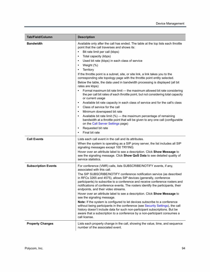
Device Management
Polycom, Inc. 94
Bandwidth Available only after the call has ended. The table at the top lists each throttle point that the call traverses and shows its:
• Bit rate limit per call (kbps)
• Total capacity (kbps)
• Used bit rate (kbps) in each class of service
• Weight (%)
• Territory
If the throttle point is a subnet, site, or site link, a link takes you to the corresponding site topology page with the throttle point entity selected.
Below the table, the data used in bandwidth processing is displayed (all bit rates are kbps):
• Formal maximum bit rate limit — the maximum allowed bit rate considering the per call bit rates of each throttle point, but not considering total capacity or current usage
• Available bit rate capacity in each class of service and for the call’s class
• Class of service for the call
• Minimum downspeed bit rate
• Available bit rate limit (%) — the maximum percentage of remaining bandwidth at a throttle point that will be given to any one call (configurable on the Call Server Settings page)
• Requested bit rate
• Final bit rate
Call Events Lists each call event in the call and its attributes.
When the system is operating as a SIP proxy server, the list includes all SIP signaling messages except 100 TRYING.
Hover over an attribute label to see a description. Click Show Message to see the signaling message. Click Show QoS Data to see detailed quality of service statistics.
Subscription Events For conference (VMR) calls, lists SUBSCRIBE/NOTIFY events, if any, associated with this call.
The SIP SUBSCRIBE/NOTIFY conference notification service (as described in RFCs 3265 and 4575), allows SIP devices (generally, conference participants) to subscribe to a conference and receive conference rosters and notifications of conference events. The rosters identify the participants, their endpoints, and their video streams.
Hover over an attribute label to see a description. Click Show Message to see the signaling message.
Note: If the system is configured to let devices subscribe to a conference without being participants in the conference (see Security Settings), the call history doesn’t include data for such non-participant subscriptions. But be aware that a subscription to a conference by a non-participant consumes a call license.
Property Changes Lists each property change in the call, showing the value, time, and sequence number of the associated event.
Tab/Field/Column Description
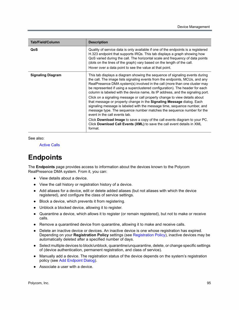
Device Management
Polycom, Inc. 95
See also:
Active Calls
EndpointsThe Endpoints page provides access to information about the devices known to the Polycom RealPresence DMA system. From it, you can:
● View details about a device.
● View the call history or registration history of a device.
● Add aliases for a device, edit or delete added aliases (but not aliases with which the device registered), and configure the class of service settings.
● Block a device, which prevents it from registering.
● Unblock a blocked device, allowing it to register.
● Quarantine a device, which allows it to register (or remain registered), but not to make or receive calls.
● Remove a quarantined device from quarantine, allowing it to make and receive calls.
● Delete an inactive device or devices. An inactive device is one whose registration has expired. Depending on your Registration Policy settings (see Registration Policy), inactive devices may be automatically deleted after a specified number of days.
● Select multiple devices to block/unblock, quarantine/unquarantine, delete, or change specific settings of (device authentication, permanent registration, and class of service).
● Manually add a device. The registration status of the device depends on the system’s registration policy (see Add Endpoint Dialog).
● Associate a user with a device.
QoS Quality of service data is only available if one of the endpoints is a registered H.323 endpoint that supports IRQs. This tab displays a graph showing how QoS varied during the call. The horizontal scale and frequency of data points (dots on the lines of the graph) vary based on the length of the call.
Hover over a data point to see the value at that point.
Signaling Diagram This tab displays a diagram showing the sequence of signaling events during the call. The image lists signaling events from the endpoints, MCUs, and any RealPresence DMA system(s) involved in the call (more than one cluster may be represented if using a superclustered configuration). The header for each column is labeled with the device name, its IP address, and the signaling port.
Click on a signaling message or call property change to view details about that message or property change in the Signaling Message dialog. Each signaling message is labeled with the message time, sequence number, and message type. The sequence number matches the sequence number for the event in the call events tab.
Click Download Image to save a copy of the call events diagram to your PC. Click Download Call Events (XML) to save the call event details in XML format.
Tab/Field/Column Description
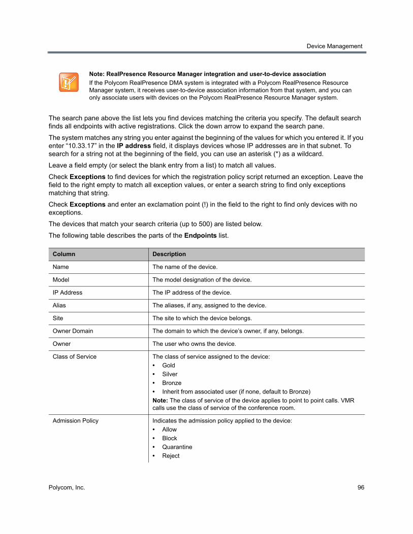
Device Management
Polycom, Inc. 96
The search pane above the list lets you find devices matching the criteria you specify. The default search finds all endpoints with active registrations. Click the down arrow to expand the search pane.
The system matches any string you enter against the beginning of the values for which you entered it. If you enter “10.33.17” in the IP address field, it displays devices whose IP addresses are in that subnet. To search for a string not at the beginning of the field, you can use an asterisk (*) as a wildcard.
Leave a field empty (or select the blank entry from a list) to match all values.
Check Exceptions to find devices for which the registration policy script returned an exception. Leave the field to the right empty to match all exception values, or enter a search string to find only exceptions matching that string.
Check Exceptions and enter an exclamation point (!) in the field to the right to find only devices with no exceptions.
The devices that match your search criteria (up to 500) are listed below.
The following table describes the parts of the Endpoints list.
Note: RealPresence Resource Manager integration and user-to-device association
If the Polycom RealPresence DMA system is integrated with a Polycom RealPresence Resource Manager system, it receives user-to-device association information from that system, and you can only associate users with devices on the Polycom RealPresence Resource Manager system.
Column Description
Name The name of the device.
Model The model designation of the device.
IP Address The IP address of the device.
Alias The aliases, if any, assigned to the device.
Site The site to which the device belongs.
Owner Domain The domain to which the device’s owner, if any, belongs.
Owner The user who owns the device.
Class of Service The class of service assigned to the device:
• Gold
• Silver
• Bronze
• Inherit from associated user (if none, default to Bronze)
Note: The class of service of the device applies to point to point calls. VMR calls use the class of service of the conference room.
Admission Policy Indicates the admission policy applied to the device:
• Allow
• Block
• Quarantine
• Reject
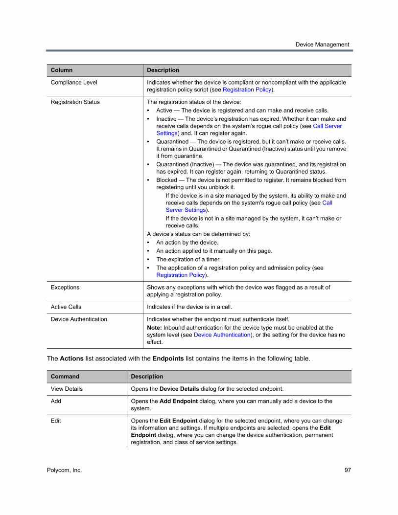
Device Management
Polycom, Inc. 97
The Actions list associated with the Endpoints list contains the items in the following table.
Compliance Level Indicates whether the device is compliant or noncompliant with the applicable registration policy script (see Registration Policy).
Registration Status The registration status of the device:
• Active — The device is registered and can make and receive calls.
• Inactive — The device’s registration has expired. Whether it can make and receive calls depends on the system’s rogue call policy (see Call Server Settings) and. It can register again.
• Quarantined — The device is registered, but it can’t make or receive calls. It remains in Quarantined or Quarantined (Inactive) status until you remove it from quarantine.
• Quarantined (Inactive) — The device was quarantined, and its registration has expired. It can register again, returning to Quarantined status.
• Blocked — The device is not permitted to register. It remains blocked from registering until you unblock it.
If the device is in a site managed by the system, its ability to make and receive calls depends on the system's rogue call policy (see Call Server Settings).
If the device is not in a site managed by the system, it can’t make or receive calls.
A device’s status can be determined by:
• An action by the device.
• An action applied to it manually on this page.
• The expiration of a timer.
• The application of a registration policy and admission policy (see Registration Policy).
Exceptions Shows any exceptions with which the device was flagged as a result of applying a registration policy.
Active Calls Indicates if the device is in a call.
Device Authentication Indicates whether the endpoint must authenticate itself.
Note: Inbound authentication for the device type must be enabled at the system level (see Device Authentication), or the setting for the device has no effect.
Command Description
View Details Opens the Device Details dialog for the selected endpoint.
Add Opens the Add Endpoint dialog, where you can manually add a device to the system.
Edit Opens the Edit Endpoint dialog for the selected endpoint, where you can change its information and settings. If multiple endpoints are selected, opens the Edit Endpoint dialog, where you can change the device authentication, permanent registration, and class of service settings.
Column Description
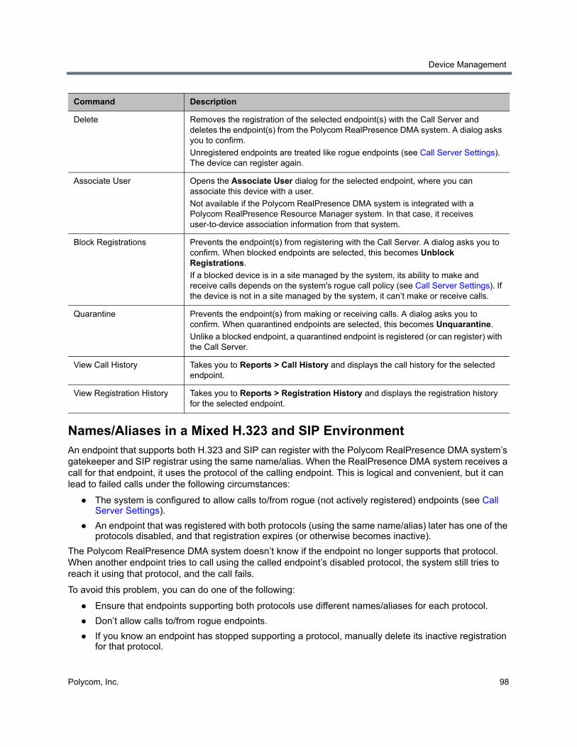
Device Management
Polycom, Inc. 98
Names/Aliases in a Mixed H.323 and SIP Environment An endpoint that supports both H.323 and SIP can register with the Polycom RealPresence DMA system’s gatekeeper and SIP registrar using the same name/alias. When the RealPresence DMA system receives a call for that endpoint, it uses the protocol of the calling endpoint. This is logical and convenient, but it can lead to failed calls under the following circumstances:
● The system is configured to allow calls to/from rogue (not actively registered) endpoints (see Call Server Settings).
● An endpoint that was registered with both protocols (using the same name/alias) later has one of the protocols disabled, and that registration expires (or otherwise becomes inactive).
The Polycom RealPresence DMA system doesn’t know if the endpoint no longer supports that protocol. When another endpoint tries to call using the called endpoint’s disabled protocol, the system still tries to reach it using that protocol, and the call fails.
To avoid this problem, you can do one of the following:
● Ensure that endpoints supporting both protocols use different names/aliases for each protocol.
● Don’t allow calls to/from rogue endpoints.
● If you know an endpoint has stopped supporting a protocol, manually delete its inactive registration for that protocol.
Delete Removes the registration of the selected endpoint(s) with the Call Server and deletes the endpoint(s) from the Polycom RealPresence DMA system. A dialog asks you to confirm.
Unregistered endpoints are treated like rogue endpoints (see Call Server Settings). The device can register again.
Associate User Opens the Associate User dialog for the selected endpoint, where you can associate this device with a user.
Not available if the Polycom RealPresence DMA system is integrated with a Polycom RealPresence Resource Manager system. In that case, it receives user-to-device association information from that system.
Block Registrations Prevents the endpoint(s) from registering with the Call Server. A dialog asks you to confirm. When blocked endpoints are selected, this becomes Unblock Registrations.
If a blocked device is in a site managed by the system, its ability to make and receive calls depends on the system's rogue call policy (see Call Server Settings). If the device is not in a site managed by the system, it can’t make or receive calls.
Quarantine Prevents the endpoint(s) from making or receiving calls. A dialog asks you to confirm. When quarantined endpoints are selected, this becomes Unquarantine.
Unlike a blocked endpoint, a quarantined endpoint is registered (or can register) with the Call Server.
View Call History Takes you to Reports > Call History and displays the call history for the selected endpoint.
View Registration History Takes you to Reports > Registration History and displays the registration history for the selected endpoint.
Command Description
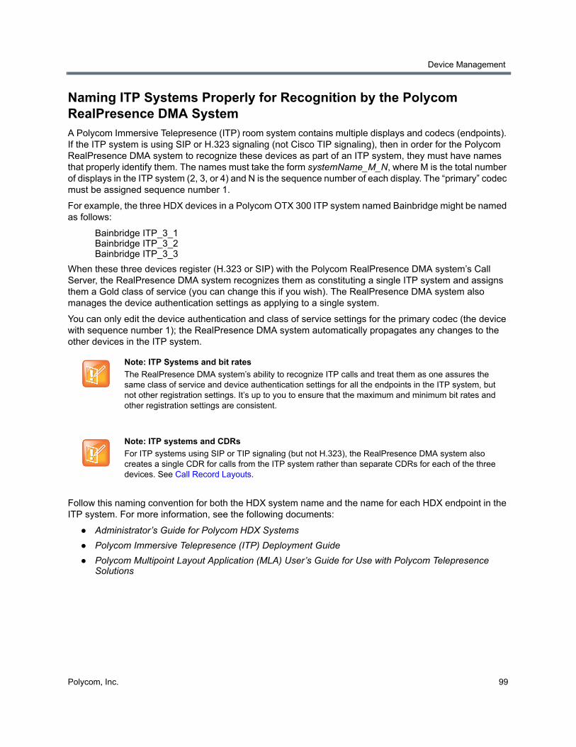
Device Management
Polycom, Inc. 99
Naming ITP Systems Properly for Recognition by the Polycom RealPresence DMA System A Polycom Immersive Telepresence (ITP) room system contains multiple displays and codecs (endpoints). If the ITP system is using SIP or H.323 signaling (not Cisco TIP signaling), then in order for the Polycom RealPresence DMA system to recognize these devices as part of an ITP system, they must have names that properly identify them. The names must take the form systemName_M_N, where M is the total number of displays in the ITP system (2, 3, or 4) and N is the sequence number of each display. The “primary” codec must be assigned sequence number 1.
For example, the three HDX devices in a Polycom OTX 300 ITP system named Bainbridge might be named as follows:
Bainbridge ITP_3_1 Bainbridge ITP_3_2 Bainbridge ITP_3_3
When these three devices register (H.323 or SIP) with the Polycom RealPresence DMA system’s Call Server, the RealPresence DMA system recognizes them as constituting a single ITP system and assigns them a Gold class of service (you can change this if you wish). The RealPresence DMA system also manages the device authentication settings as applying to a single system.
You can only edit the device authentication and class of service settings for the primary codec (the device with sequence number 1); the RealPresence DMA system automatically propagates any changes to the other devices in the ITP system.
Follow this naming convention for both the HDX system name and the name for each HDX endpoint in the ITP system. For more information, see the following documents:
● Administrator’s Guide for Polycom HDX Systems
● Polycom Immersive Telepresence (ITP) Deployment Guide
● Polycom Multipoint Layout Application (MLA) User’s Guide for Use with Polycom Telepresence Solutions
Note: ITP Systems and bit rates
The RealPresence DMA system’s ability to recognize ITP calls and treat them as one assures the same class of service and device authentication settings for all the endpoints in the ITP system, but not other registration settings. It’s up to you to ensure that the maximum and minimum bit rates and other registration settings are consistent.
Note: ITP systems and CDRs
For ITP systems using SIP or TIP signaling (but not H.323), the RealPresence DMA system also creates a single CDR for calls from the ITP system rather than separate CDRs for each of the three devices. See Call Record Layouts.
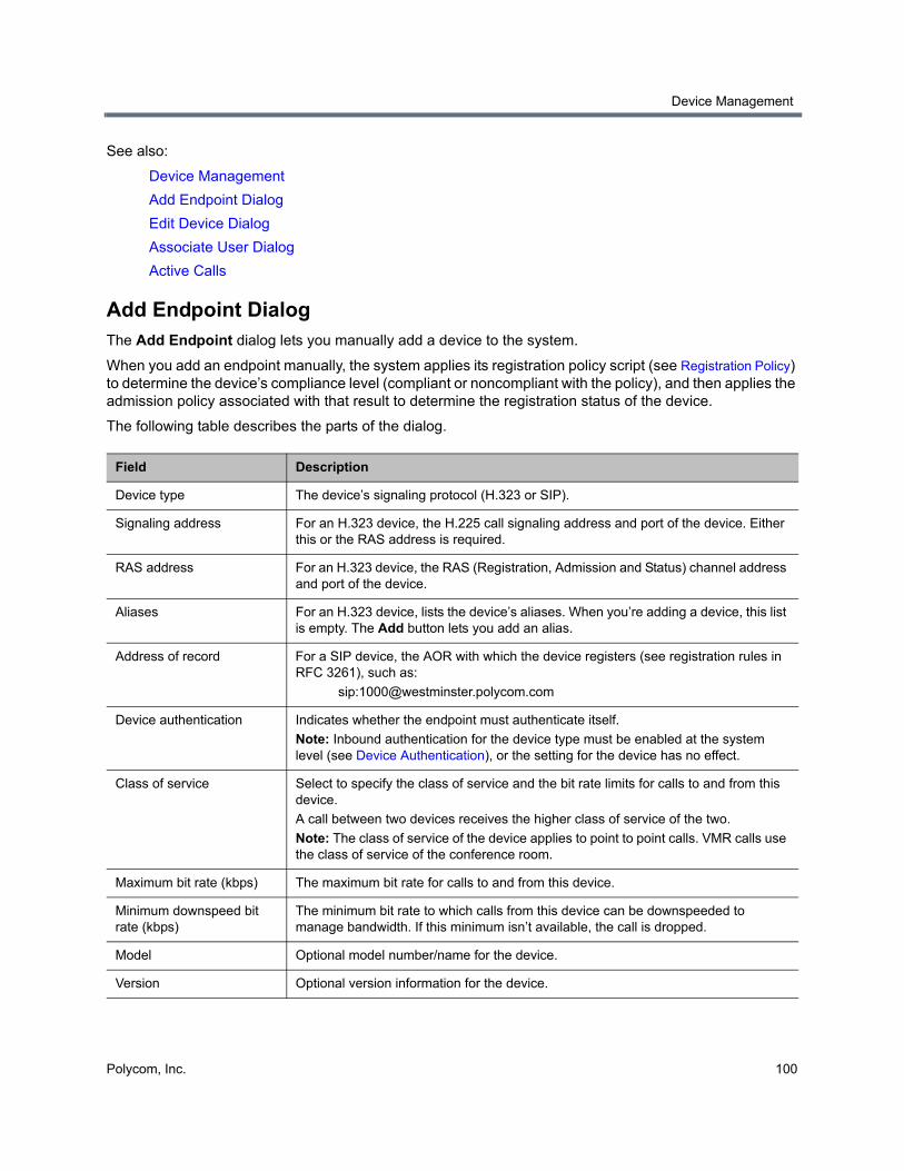
Device Management
Polycom, Inc. 100
See also:
Device Management
Add Endpoint Dialog
Edit Device Dialog
Associate User Dialog
Active Calls
Add Endpoint DialogThe Add Endpoint dialog lets you manually add a device to the system.
When you add an endpoint manually, the system applies its registration policy script (see Registration Policy) to determine the device’s compliance level (compliant or noncompliant with the policy), and then applies the admission policy associated with that result to determine the registration status of the device.
The following table describes the parts of the dialog.
Field Description
Device type The device’s signaling protocol (H.323 or SIP).
Signaling address For an H.323 device, the H.225 call signaling address and port of the device. Either this or the RAS address is required.
RAS address For an H.323 device, the RAS (Registration, Admission and Status) channel address and port of the device.
Aliases For an H.323 device, lists the device’s aliases. When you’re adding a device, this list is empty. The Add button lets you add an alias.
Address of record For a SIP device, the AOR with which the device registers (see registration rules in RFC 3261), such as:
Device authentication Indicates whether the endpoint must authenticate itself.
Note: Inbound authentication for the device type must be enabled at the system level (see Device Authentication), or the setting for the device has no effect.
Class of service Select to specify the class of service and the bit rate limits for calls to and from this device.
A call between two devices receives the higher class of service of the two.
Note: The class of service of the device applies to point to point calls. VMR calls use the class of service of the conference room.
Maximum bit rate (kbps) The maximum bit rate for calls to and from this device.
Minimum downspeed bit rate (kbps)
The minimum bit rate to which calls from this device can be downspeeded to manage bandwidth. If this minimum isn’t available, the call is dropped.
Model Optional model number/name for the device.
Version Optional version information for the device.
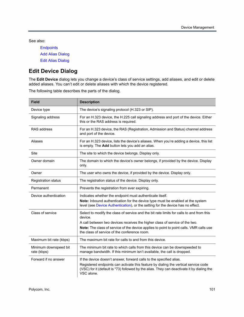
Device Management
Polycom, Inc. 101
See also:
Endpoints
Add Alias Dialog
Edit Alias Dialog
Edit Device DialogThe Edit Device dialog lets you change a device’s class of service settings, add aliases, and edit or delete added aliases. You can’t edit or delete aliases with which the device registered.
The following table describes the parts of the dialog.
Field Description
Device type The device’s signaling protocol (H.323 or SIP).
Signaling address For an H.323 device, the H.225 call signaling address and port of the device. Either this or the RAS address is required.
RAS address For an H.323 device, the RAS (Registration, Admission and Status) channel address and port of the device.
Aliases For an H.323 device, lists the device’s aliases. When you’re adding a device, this list is empty. The Add button lets you add an alias.
Site The site to which the device belongs. Display only.
Owner domain The domain to which the device’s owner belongs, if provided by the device. Display only.
Owner The user who owns the device, if provided by the device. Display only.
Registration status The registration status of the device. Display only.
Permanent Prevents the registration from ever expiring.
Device authentication Indicates whether the endpoint must authenticate itself.
Note: Inbound authentication for the device type must be enabled at the system level (see Device Authentication), or the setting for the device has no effect.
Class of service Select to modify the class of service and the bit rate limits for calls to and from this device.
A call between two devices receives the higher class of service of the two.
Note: The class of service of the device applies to point to point calls. VMR calls use the class of service of the conference room.
Maximum bit rate (kbps) The maximum bit rate for calls to and from this device.
Minimum downspeed bit rate (kbps)
The minimum bit rate to which calls from this device can be downspeeded to manage bandwidth. If this minimum isn’t available, the call is dropped.
Forward if no answer If the device doesn’t answer, forward calls to the specified alias.
Registered endpoints can activate this feature by dialing the vertical service code (VSC) for it (default is *73) followed by the alias. They can deactivate it by dialing the VSC alone.
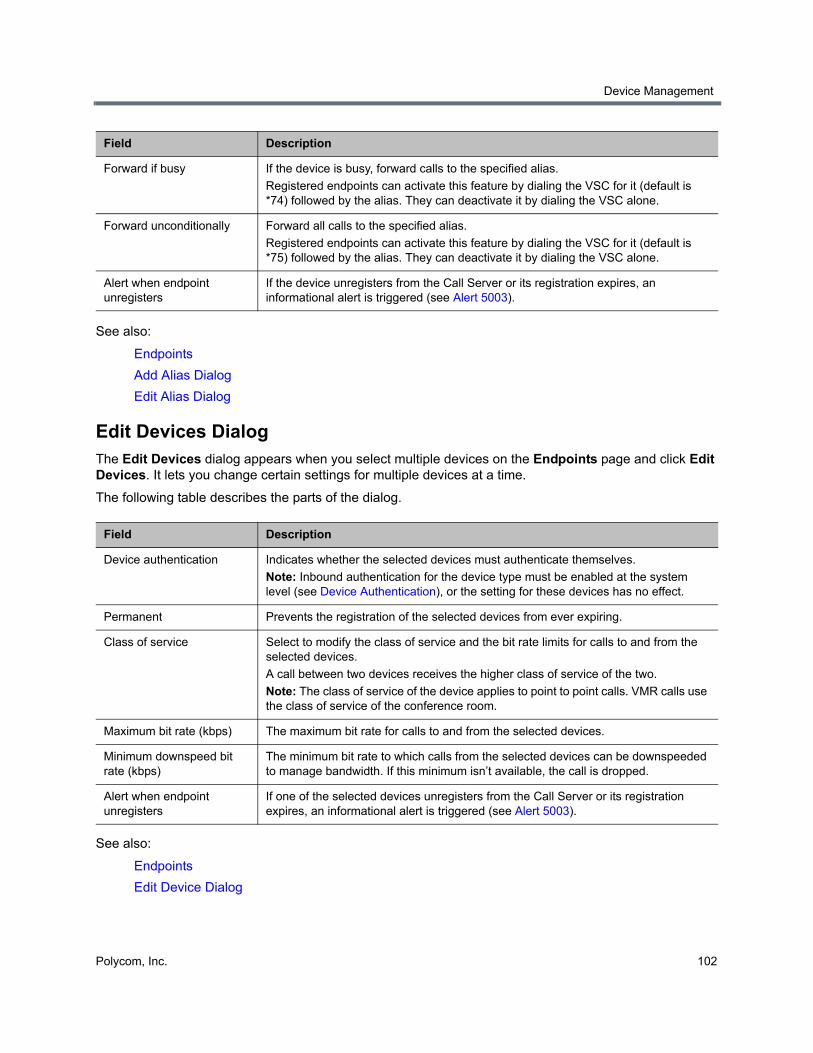
Device Management
Polycom, Inc. 102
See also:
Endpoints
Add Alias Dialog
Edit Alias Dialog
Edit Devices DialogThe Edit Devices dialog appears when you select multiple devices on the Endpoints page and click Edit Devices. It lets you change certain settings for multiple devices at a time.
The following table describes the parts of the dialog.
See also:
Endpoints
Edit Device Dialog
Forward if busy If the device is busy, forward calls to the specified alias.
Registered endpoints can activate this feature by dialing the VSC for it (default is *74) followed by the alias. They can deactivate it by dialing the VSC alone.
Forward unconditionally Forward all calls to the specified alias.
Registered endpoints can activate this feature by dialing the VSC for it (default is *75) followed by the alias. They can deactivate it by dialing the VSC alone.
Alert when endpoint unregisters
If the device unregisters from the Call Server or its registration expires, an informational alert is triggered (see Alert 5003).
Field Description
Device authentication Indicates whether the selected devices must authenticate themselves.
Note: Inbound authentication for the device type must be enabled at the system level (see Device Authentication), or the setting for these devices has no effect.
Permanent Prevents the registration of the selected devices from ever expiring.
Class of service Select to modify the class of service and the bit rate limits for calls to and from the selected devices.
A call between two devices receives the higher class of service of the two.
Note: The class of service of the device applies to point to point calls. VMR calls use the class of service of the conference room.
Maximum bit rate (kbps) The maximum bit rate for calls to and from the selected devices.
Minimum downspeed bit rate (kbps)
The minimum bit rate to which calls from the selected devices can be downspeeded to manage bandwidth. If this minimum isn’t available, the call is dropped.
Alert when endpoint unregisters
If one of the selected devices unregisters from the Call Server or its registration expires, an informational alert is triggered (see Alert 5003).
Field Description
Device Management
Polycom, Inc. 103
Add Alias DialogThe Add Alias dialog lets you specify an alias for the H.323 device you’re adding or editing. Enter the alias in the Value box and click OK.
See also:
Endpoints
Add Endpoint Dialog
Edit Device Dialog
Edit Alias DialogThe Edit Alias dialog lets you change the selected alias for the H.323 device you’re editing. You can’t edit aliases with which the device registered, only those that have been added. Edit the alias in the Value box and click OK.
See also:
Endpoints
Edit Device Dialog
Associate User Dialog
The Associate User dialog lets you associate the selected device with a user. Use the search fields at the top to find the user you want to associate with this device.
You can search by user ID, first name, or last name. The Search users field searches all three for matches. The system matches the string you enter against the beginning of the field you’re searching. For instance, if you enter “sa” in the Last name field, it displays users whose last names begin with “sa.” To search for a string not at the beginning of the field, you can use an asterisk (*) as a wildcard.
When you find the right user, select that row and click OK. A prompt asks you to confirm associating the endpoint with this user.
See also:
Endpoints
Site StatisticsThe Site Statistics page lists the sites defined in the Polycom RealPresence DMA system’s site topology and, for those controlled by the system, traffic and QoS statistics. Network clouds and the default internet site aren’t included.
The following table describes the fields in the list.
Note: RealPresence Resource Manager integration and user-to-device association
If the Polycom RealPresence DMA system is integrated with a Polycom RealPresence Resource Manager system, it receives user-to-device association information from that system, and you can only associate users with devices on the Polycom RealPresence Resource Manager system.
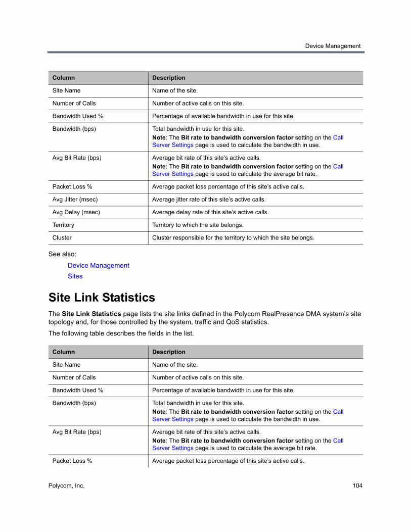
Device Management
Polycom, Inc. 104
See also:
Device Management
Sites
Site Link StatisticsThe Site Link Statistics page lists the site links defined in the Polycom RealPresence DMA system’s site topology and, for those controlled by the system, traffic and QoS statistics.
The following table describes the fields in the list.
Column Description
Site Name Name of the site.
Number of Calls Number of active calls on this site.
Bandwidth Used % Percentage of available bandwidth in use for this site.
Bandwidth (bps) Total bandwidth in use for this site.
Note: The Bit rate to bandwidth conversion factor setting on the Call Server Settings page is used to calculate the bandwidth in use.
Avg Bit Rate (bps) Average bit rate of this site’s active calls.
Note: The Bit rate to bandwidth conversion factor setting on the Call Server Settings page is used to calculate the average bit rate.
Packet Loss % Average packet loss percentage of this site’s active calls.
Avg Jitter (msec) Average jitter rate of this site’s active calls.
Avg Delay (msec) Average delay rate of this site’s active calls.
Territory Territory to which the site belongs.
Cluster Cluster responsible for the territory to which the site belongs.
Column Description
Site Name Name of the site.
Number of Calls Number of active calls on this site.
Bandwidth Used % Percentage of available bandwidth in use for this site.
Bandwidth (bps) Total bandwidth in use for this site.
Note: The Bit rate to bandwidth conversion factor setting on the Call Server Settings page is used to calculate the bandwidth in use.
Avg Bit Rate (bps) Average bit rate of this site’s active calls.
Note: The Bit rate to bandwidth conversion factor setting on the Call Server Settings page is used to calculate the average bit rate.
Packet Loss % Average packet loss percentage of this site’s active calls.
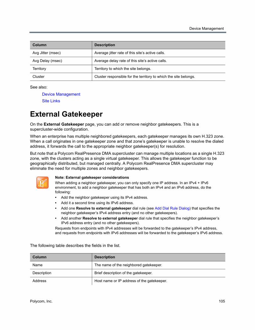
Device Management
Polycom, Inc. 105
See also:
Device Management
Site Links
External GatekeeperOn the External Gatekeeper page, you can add or remove neighbor gatekeepers. This is a supercluster-wide configuration.
When an enterprise has multiple neighbored gatekeepers, each gatekeeper manages its own H.323 zone. When a call originates in one gatekeeper zone and that zone’s gatekeeper is unable to resolve the dialed address, it forwards the call to the appropriate neighbor gatekeeper(s) for resolution.
But note that a Polycom RealPresence DMA supercluster can manage multiple locations as a single H.323 zone, with the clusters acting as a single virtual gatekeeper. This allows the gatekeeper function to be geographically distributed, but managed centrally. A Polycom RealPresence DMA supercluster may eliminate the need for multiple zones and neighbor gatekeepers.
The following table describes the fields in the list.
Avg Jitter (msec) Average jitter rate of this site’s active calls.
Avg Delay (msec) Average delay rate of this site’s active calls.
Territory Territory to which the site belongs.
Cluster Cluster responsible for the territory to which the site belongs.
Note: External gatekeeper considerations
When adding a neighbor gatekeeper, you can only specify one IP address. In an IPv4 + IPv6 environment, to add a neighbor gatekeeper that has both an IPv4 and an IPv6 address, do the following:
• Add the neighbor gatekeeper using its IPv4 address.
• Add it a second time using its IPv6 address.
• Add one Resolve to external gatekeeper dial rule (see Add Dial Rule Dialog) that specifies the neighbor gatekeeper’s IPv4 address entry (and no other gatekeepers).
• Add another Resolve to external gatekeeper dial rule that specifies the neighbor gatekeeper’s IPv6 address entry (and no other gatekeepers).
Requests from endpoints with IPv4 addresses will be forwarded to the gatekeeper’s IPv4 address, and requests from endpoints with IPv6 addresses will be forwarded to the gatekeeper’s IPv6 address.
Column Description
Name The name of the neighbored gatekeeper.
Description Brief description of the gatekeeper.
Address Host name or IP address of the gatekeeper.
Column Description
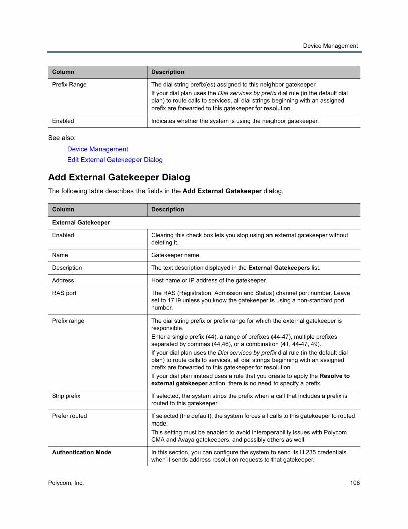
Device Management
Polycom, Inc. 106
See also:
Device Management
Edit External Gatekeeper Dialog
Add External Gatekeeper DialogThe following table describes the fields in the Add External Gatekeeper dialog.
Prefix Range The dial string prefix(es) assigned to this neighbor gatekeeper.
If your dial plan uses the Dial services by prefix dial rule (in the default dial plan) to route calls to services, all dial strings beginning with an assigned prefix are forwarded to this gatekeeper for resolution.
Enabled Indicates whether the system is using the neighbor gatekeeper.
Column Description
External Gatekeeper
Enabled Clearing this check box lets you stop using an external gatekeeper without deleting it.
Name Gatekeeper name.
Description The text description displayed in the External Gatekeepers list.
Address Host name or IP address of the gatekeeper.
RAS port The RAS (Registration, Admission and Status) channel port number. Leave set to 1719 unless you know the gatekeeper is using a non-standard port number.
Prefix range The dial string prefix or prefix range for which the external gatekeeper is responsible.
Enter a single prefix (44), a range of prefixes (44-47), multiple prefixes separated by commas (44,46), or a combination (41, 44-47, 49).
If your dial plan uses the Dial services by prefix dial rule (in the default dial plan) to route calls to services, all dial strings beginning with an assigned prefix are forwarded to this gatekeeper for resolution.
If your dial plan instead uses a rule that you create to apply the Resolve to external gatekeeper action, there is no need to specify a prefix.
Strip prefix If selected, the system strips the prefix when a call that includes a prefix is routed to this gatekeeper.
Prefer routed If selected (the default), the system forces all calls to this gatekeeper to routed mode.
This setting must be enabled to avoid interoperability issues with Polycom CMA and Avaya gatekeepers, and possibly others as well.
Authentication Mode In this section, you can configure the system to send its H.235 credentials when it sends address resolution requests to that gatekeeper.
Column Description
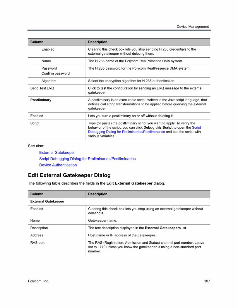
Device Management
Polycom, Inc. 107
See also:
External Gatekeeper
Script Debugging Dialog for Preliminaries/Postliminaries
Device Authentication
Edit External Gatekeeper DialogThe following table describes the fields in the Edit External Gatekeeper dialog.
Enabled Clearing this check box lets you stop sending H.235 credentials to the external gatekeeper without deleting them.
Name The H.235 name of the Polycom RealPresence DMA system.
Password
Confirm password
The H.235 password for the Polycom RealPresence DMA system.
Algorithm Select the encryption algorithm for H.235 authentication.
Send Test LRQ Click to test the configuration by sending an LRQ message to the external gatekeeper.
Postliminary A postliminary is an executable script, written in the Javascript language, that defines dial string transformations to be applied before querying the external gatekeeper.
Enabled Lets you turn a postliminary on or off without deleting it.
Script Type (or paste) the postliminary script you want to apply. To verify the behavior of the script, you can click Debug this Script to open the Script Debugging Dialog for Preliminaries/Postliminaries and test the script with various variables.
Column Description
External Gatekeeper
Enabled Clearing this check box lets you stop using an external gatekeeper without deleting it.
Name Gatekeeper name.
Description The text description displayed in the External Gatekeepers list.
Address Host name or IP address of the gatekeeper.
RAS port The RAS (Registration, Admission and Status) channel port number. Leave set to 1719 unless you know the gatekeeper is using a non-standard port number.
Column Description
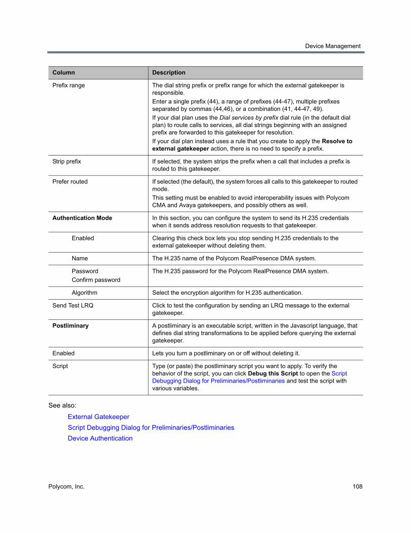
Device Management
Polycom, Inc. 108
See also:
External Gatekeeper
Script Debugging Dialog for Preliminaries/Postliminaries
Device Authentication
Prefix range The dial string prefix or prefix range for which the external gatekeeper is responsible.
Enter a single prefix (44), a range of prefixes (44-47), multiple prefixes separated by commas (44,46), or a combination (41, 44-47, 49).
If your dial plan uses the Dial services by prefix dial rule (in the default dial plan) to route calls to services, all dial strings beginning with an assigned prefix are forwarded to this gatekeeper for resolution.
If your dial plan instead uses a rule that you create to apply the Resolve to external gatekeeper action, there is no need to specify a prefix.
Strip prefix If selected, the system strips the prefix when a call that includes a prefix is routed to this gatekeeper.
Prefer routed If selected (the default), the system forces all calls to this gatekeeper to routed mode.
This setting must be enabled to avoid interoperability issues with Polycom CMA and Avaya gatekeepers, and possibly others as well.
Authentication Mode In this section, you can configure the system to send its H.235 credentials when it sends address resolution requests to that gatekeeper.
Enabled Clearing this check box lets you stop sending H.235 credentials to the external gatekeeper without deleting them.
Name The H.235 name of the Polycom RealPresence DMA system.
Password
Confirm password
The H.235 password for the Polycom RealPresence DMA system.
Algorithm Select the encryption algorithm for H.235 authentication.
Send Test LRQ Click to test the configuration by sending an LRQ message to the external gatekeeper.
Postliminary A postliminary is an executable script, written in the Javascript language, that defines dial string transformations to be applied before querying the external gatekeeper.
Enabled Lets you turn a postliminary on or off without deleting it.
Script Type (or paste) the postliminary script you want to apply. To verify the behavior of the script, you can click Debug this Script to open the Script Debugging Dialog for Preliminaries/Postliminaries and test the script with various variables.
Column Description
Device Management
Polycom, Inc. 109
External SIP PeerOn the External SIP Peers page, you can add or remove SIP servers or devices from the list of SIP peers to which the system can route calls and from which it may receive calls.
This is a supercluster-wide configuration. But note that a Polycom RealPresence DMA system supercluster can provide proxy service for any or all domains in the enterprise, allowing the SIP function to be distributed, but managed centrally. This may reduce the need for external SIP peer servers (other than SIP session border controllers, or SBCs).
Multiple External SIP PeersThe RealPresence DMA system can use multiple SIP peers to resolve dial strings. If a SIP peer experiences an outage, it is marked as unresponsive, and the RealPresence DMA system stops using it until it becomes responsive again. If you add multiple SIP peers to the system, you can configure how the system selects which SIP peer to use to resolve dial strings using a dial rule with the Resolve to external SIP peer action.
When you configure a dial rule that uses the Resolve to external SIP peer action, you can choose which of two selection policies (All in parallel (forking) or Weighted round-robin) the system uses to resolve dial strings to SIP peers. If you select All in parallel (forking), the system tries all SIP peers simultaneously. If you select Weighted round-robin, you can assign each SIP peer a weight, with a higher weight giving a SIP peer higher priority, and the system tries each SIP peer sequentially according to the SIP peer’s assigned weight. You can change the weight for each SIP peer using the dialog’s Edit weight button. Unresponsive SIP peers are considered only when there are no responsive peers that can complete the call.
See Dial Rules for more information.
The following table describes the fields in the list of SIP peers on the External SIP Peers page.
Note: SBC configuration
SIP SBCs to be reached by prefix-based dialing (rule 4 of the default dial plan; see The Default Dial Plan and Suggestions for Modifications) are added to the External SIP Peers page.
SBCs to be reached by a dial rule using the Resolve to external address or Resolve to IP address action (rules 5 and 6, respectively, of the default dial plan) are configured on a per-site basis (see Edit Site Dialog).
For most configurations, SBCs should be configured on a per-site basis, so that calls to endpoints outside the enterprise network are routed to the SBC for the originating site.
Note: SIP peer availability and third-party network equipment
The RealPresence DMA system periodically uses SIP OPTIONS messages to verify connectivity with SIP peers. If a SIP peer fails to respond or responds with a specified set of status codes, the system removes that SIP peer from service. In some situations, a third-party device can respond on behalf of the SIP peer. If the RealPresence DMA system receives any other status code when the queried SIP peer is experiencing an outage, that SIP peer could incorrectly be marked as healthy.
Because of this, it is possible for a SIP peer’s service status to enter a “flapping” state. In this scenario, the RealPresence DMA system attempts to use the incorrectly marked SIP peer, but when the SIP peer fails to respond, the RealPresence DMA system removes the SIP peer from service. However, the RealPresence DMA system receives a non-specified status code response for the next availability query, so puts the SIP peer back in service.
Device Management
Polycom, Inc. 110
See also:
Device Management
Edit External SIP Peer Dialog
Add External SIP Peer DialogThe following table describes the fields in the Add External SIP Peer dialog.
Column Description
UDP TCP TLS Provides a visual responsiveness status of each SIP peer for the UDP, TCP, and TLS protocols, depending on what Transport type the system is configured to use when contacting this SIP peer. If the Transport type is set to Auto Detect, the system may use multiple transport types and may display an icon indicating responsiveness for each type it uses.
Responsiveness status for each SIP peer in the list is updated every ten seconds by default.
Name The name of the SIP peer.
Description Brief description of the SIP peer.
Next Hop Address Fully qualified domain name (FQDN) or IP address of the SIP peer
Prefix Range The dial string prefix(es) assigned to this SIP peer.
If your dial plan uses the Dial services by prefix dial rule (in the default dial plan) to route calls to services, all dial strings beginning with an assigned prefix are forwarded to this SIP peer for resolution.
Enabled Indicates whether the system is using the SIP peer.
External Registrations Indicates whether the system is registered with the SIP peer so that it can route calls to it. Displays “Active” if there are any External Registrations defined for this SIP peer that are enabled.
Field Description
External SIP Peers
Enabled Clearing this check box lets you stop using an external SIP peer without deleting it.
Name Peer name or number. Must be unique among SIP peers.
Description The text description displayed in the External SIP Peer list.
Type For a Microsoft Office Communications Server, Lync Server 2010, or Lync Server 2013, select Microsoft. Otherwise, select Other.
Selecting Microsoft implicitly adds the Destination network value to the Domain List (if not already there) and automatically selects the Postliminary settings that are correct for most deployments in Microsoft environments, but you can modify them if necessary.
Note: Selecting Microsoft enables the Lync Integration tab.
Device Management
Polycom, Inc. 111
Next hop address Fully qualified domain name (FQDN), host name, or IP address of the SIP peer. Spaces after the name are not allowed.
If you specify a domain/host name, the system routes calls to this peer by using DNS to resolve the address. The DNS server that the system uses must contain the required records (NAPTR, SRV, and/or A/AAAA).
Note: If you are configuring a Lync 2013 SIP Peer, the Next hop address should be the FQDN or IP address of the Lync Pool, not an individual Lync server within a pool.
Destination network Host name, FQDN, or network domain label of the SIP peer, with or without port and URL parameters.
If specified, this value by default replaces the non-user portion of a URL (after the @ symbol) of the To header and Request-URI for forwarded messages, and just the Request-URI for REGISTER messages.
If Type is set to Microsoft, this field is required and is used for the peer’s domain.
Note: This field is used as the SIP domain for Polycom RealConnect™ conferences.
Port The SIP signaling port number. Defaults to the standard UDP/TCP port, 5060. If the peer server is using a different port number, specify it.
Note: For a Microsoft Lync 2013 SIP peer, the port should be 5061.
If left blank, the system uses the full RFC 3263 procedure to determine the port via DNS.
Transport type The transport protocol to use when contacting this SIP peer. The default is UDP.
Auto detect tells the system to select the protocol using DNS as specified in RFC 3263, and is not valid if Next hop address is a numeric IP address instead of a host/domain name.
Use route header Add a Route header with the peer’s Next hop address value to the message. Applies to both forwarded messages and external REGISTER messages.
If not selected, the only valid Request-URI configurations are those that use the peer's Next hop address value for the URI host.
Note: Disable this option for Microsoft Lync SIP peers that will accept content sessions from Polycom RealPresence ContentConnectTM applications through the RealPresence DMA system.
Downgrade If selected, and if this peer doesn’t support TLS, the system can change the Request-URI schema from sips to sip and route the call to this peer.
If not selected, the system routes a TLS call to this peer only if this peer supports TLS.
Field Description
Device Management
Polycom, Inc. 112
Prefix range The dial string prefix(es) assigned to this SIP peer.
Enter a single prefix (44), a range of prefixes (44-47), or multiple prefixes separated by commas (44,46)
If your dial plan uses the Dial services by prefix dial rule (in the default dial plan) to route calls to services, all dial strings beginning with an assigned prefix are forwarded to this SIP peer for resolution.
If your dial plan instead uses a rule that you create to apply the Resolve to external SIP peer action, there is no need to specify a prefix.
Otherwise, the system applies the SIP Routing settings of the originating site (see Sites and Edit Site Dialog) for calls to endpoints outside the enterprise network.
Note: For a SIP peer, the dial string must either include the protocol or consist of only the prefix and user name (no @domain). For instance, if the SIP peer’s prefix is 123, the dial string for a call to [email protected] must be one of the following:
sips:[email protected]
123alice
Strip prefix If selected, the system strips the prefix when a call that includes a prefix is routed to this peer.
Register externally Some external SIP peers require peers to register with them as an endpoint does, using a REGISTER message (also referred to as pilot registration).
Select this option to enable the External Registration tab and configure the system to register with this external SIP peer, following the rules specified in RFC 3261.
Supports SIP OPTIONS ping If selected, the system sends SIP OPTIONS ping messages to the SIP peer to determine its responsiveness. See the Admin > Call Server > Call Server Settings page for configuration options related to SIP OPTIONS ping messages.
Domain List If your dial plan uses a rule to apply the Resolve to external SIP peer action, you can restrict calls to this SIP peer to specific domains by adding the authorized domains to this list.
If this list is empty, all domains can resolve to this peer.
Note: In some circumstances (depending on network topology and configuration), dialing loops can develop if you don't restrict SIP peers to specific domains.
Add new domain Enter a domain and click Add to add it to the list of authorized domains.
Authorized domains List of administrative domains, contained in the dial string, for which calls are routed to this SIP peer.
Leave this list empty to route any call that matches the rule to this SIP peer.
Select a domain and click Remove to remove it from the list.
Field Description
Device Management
Polycom, Inc. 113
Postliminary
Enabled If checked, the fields on this page are available and in effect. If unchecked, the fields are disabled and the original SIP signaling is passed unchanged to the SIP peer.
This field is unchecked by default if you select a Type of Microsoft when adding a SIP peer.
Note: Polycom recommends leaving postliminary scripts disabled for Microsoft SIP peers to ensure proper signaling operation with calls to external Lync systems.
Use output format Enables dial string transformations using the To header and Request-URI option settings below instead of a customized script.
Note: The system generates a script that implements the settings made in this section. To see (and perhaps copy) the generated script, you can temporarily select Use customized script.
To help you learn how to write your own script, you can make different settings in this section and see how the generated script changes.
To header options Specify the format of the To header in messages sent to this peer.
Copy all parameters of original “To” headers
Copies any parameters included in the original To header to the To header sent to this peer. This setting applies to all format options.
Format
Template
Select a predefined format from the list, or select Free Form Template and define the format in the associated Template field.
The predefined formats in the list and the variables you use in the Template field are described in SIP Peer Postliminary Output Format Options.
Request URI options Specify the format of the Request-URI.
Format
Template
Select a predefined format from the list, or select Free Form Template and define the format in the associated Template field.
The predefined formats in the list and the variables you use in the Template field are described in SIP Peer Postliminary Output Format Options.
Use customized script Enables an executable script, written in the Javascript language, in the text box below. Writing such a script enables you to more flexibly define dial string and message format transformations to be applied.
Type (or paste) the postliminary script you want to apply. Then click Debug this Script to open the Script Debugging Dialog for Preliminaries/Postliminaries and test the script with various variables.
Note: When you change settings in the Use output format section, the system generates a script that implements those settings. Select this option to see (and perhaps copy) the generated script. The functions in the generated script return string values and accept string parameters.
Field Description
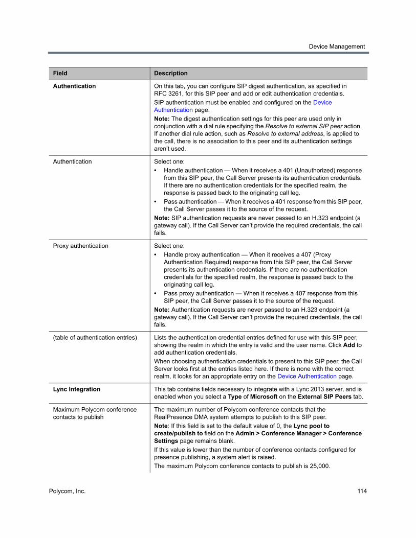
Device Management
Polycom, Inc. 114
Authentication On this tab, you can configure SIP digest authentication, as specified in RFC 3261, for this SIP peer and add or edit authentication credentials.
SIP authentication must be enabled and configured on the Device Authentication page.
Note: The digest authentication settings for this peer are used only in conjunction with a dial rule specifying the Resolve to external SIP peer action. If another dial rule action, such as Resolve to external address, is applied to the call, there is no association to this peer and its authentication settings aren’t used.
Authentication Select one:
• Handle authentication — When it receives a 401 (Unauthorized) response from this SIP peer, the Call Server presents its authentication credentials. If there are no authentication credentials for the specified realm, the response is passed back to the originating call leg.
• Pass authentication — When it receives a 401 response from this SIP peer, the Call Server passes it to the source of the request.
Note: SIP authentication requests are never passed to an H.323 endpoint (a gateway call). If the Call Server can’t provide the required credentials, the call fails.
Proxy authentication Select one:
• Handle proxy authentication — When it receives a 407 (Proxy Authentication Required) response from this SIP peer, the Call Server presents its authentication credentials. If there are no authentication credentials for the specified realm, the response is passed back to the originating call leg.
• Pass proxy authentication — When it receives a 407 response from this SIP peer, the Call Server passes it to the source of the request.
Note: Authentication requests are never passed to an H.323 endpoint (a gateway call). If the Call Server can’t provide the required credentials, the call fails.
(table of authentication entries) Lists the authentication credential entries defined for use with this SIP peer, showing the realm in which the entry is valid and the user name. Click Add to add authentication credentials.
When choosing authentication credentials to present to this SIP peer, the Call Server looks first at the entries listed here. If there is none with the correct realm, it looks for an appropriate entry on the Device Authentication page.
Lync Integration This tab contains fields necessary to integrate with a Lync 2013 server, and is enabled when you select a Type of Microsoft on the External SIP Peers tab.
Maximum Polycom conference contacts to publish
The maximum number of Polycom conference contacts that the RealPresence DMA system attempts to publish to this SIP peer.
Note: If this field is set to the default value of 0, the Lync pool to create/publish to field on the Admin > Conference Manager > Conference Settings page remains blank.
If this value is lower than the number of conference contacts configured for presence publishing, a system alert is raised.
The maximum Polycom conference contacts to publish is 25,000.
Field Description
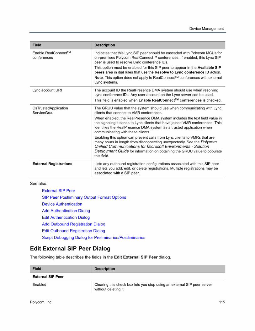
Device Management
Polycom, Inc. 115
See also:
External SIP Peer
SIP Peer Postliminary Output Format Options
Device Authentication
Add Authentication Dialog
Edit Authentication Dialog
Add Outbound Registration Dialog
Edit Outbound Registration Dialog
Script Debugging Dialog for Preliminaries/Postliminaries
Edit External SIP Peer DialogThe following table describes the fields in the Edit External SIP Peer dialog.
Enable RealConnectTM conferences
Indicates that this Lync SIP peer should be cascaded with Polycom MCUs for on-premises Polycom RealConnectTM conferences. If enabled, this Lync SIP peer is used to resolve Lync conference IDs.
This option must be enabled for this SIP peer to appear in the Available SIP peers area in dial rules that use the Resolve to Lync conference ID action.
Note: This option does not apply to RealConnectTM conferences with external Lync systems.
Lync account URI The account ID the RealPresence DMA system should use when resolving Lync conference IDs. Any user account on the Lync server can be used.
This field is enabled when Enable RealConnectTM conferences is checked.
CsTrustedApplication ServiceGruu
The GRUU value that the system should use when communicating with Lync clients that connect to VMR conferences.
When enabled, the RealPresence DMA system includes the text field value in the signaling it sends to Lync clients that have joined VMR conferences. This identifies the RealPresence DMA system as a trusted application when communicating with these clients.
Enabling this option can prevent calls from Lync clients to VMRs that are many hours in length from disconnecting unexpectedly. See the Polycom Unified Communications for Microsoft Environments - Solution Deployment Guide for information on obtaining the GRUU value to populate this field.
External Registrations Lists any outbound registration configurations associated with this SIP peer and lets you add, edit, or delete registrations. Multiple registrations may be associated with a SIP peer.
Field Description
External SIP Peer
Enabled Clearing this check box lets you stop using an external SIP peer server without deleting it.
Field Description
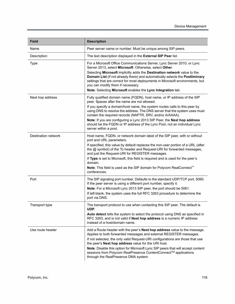
Device Management
Polycom, Inc. 116
Name Peer server name or number. Must be unique among SIP peers.
Description The text description displayed in the External SIP Peer list.
Type For a Microsoft Office Communications Server, Lync Server 2010, or Lync Server 2013, select Microsoft. Otherwise, select Other.
Selecting Microsoft implicitly adds the Destination network value to the Domain List (if not already there) and automatically selects the Postliminary settings that are correct for most deployments in Microsoft environments, but you can modify them if necessary.
Note: Selecting Microsoft enables the Lync Integration tab.
Next hop address Fully qualified domain name (FQDN), host name, or IP address of the SIP peer. Spaces after the name are not allowed.
If you specify a domain/host name, the system routes calls to this peer by using DNS to resolve the address. The DNS server that the system uses must contain the required records (NAPTR, SRV, and/or A/AAAA).
Note: If you are configuring a Lync 2013 SIP Peer, the Next hop address should be the FQDN or IP address of the Lync Pool, not an individual Lync server within a pool.
Destination network Host name, FQDN, or network domain label of the SIP peer, with or without port and URL parameters.
If specified, this value by default replaces the non-user portion of a URL (after the @ symbol) of the To header and Request-URI for forwarded messages, and just the Request-URI for REGISTER messages.
If Type is set to Microsoft, this field is required and is used for the peer’s domain.
Note: This field is used as the SIP domain for Polycom RealConnect™ conferences.
Port The SIP signaling port number. Defaults to the standard UDP/TCP port, 5060. If the peer server is using a different port number, specify it.
Note: For a Microsoft Lync 2013 SIP peer, the port should be 5061.
If left blank, the system uses the full RFC 3263 procedure to determine the port via DNS.
Transport type The transport protocol to use when contacting this SIP peer. The default is UDP.
Auto detect tells the system to select the protocol using DNS as specified in RFC 3263, and is not valid if Next hop address is a numeric IP address instead of a host/domain name.
Use route header Add a Route header with the peer’s Next hop address value to the message. Applies to both forwarded messages and external REGISTER messages.
If not selected, the only valid Request-URI configurations are those that use the peer's Next hop address value for the URI host.
Note: Disable this option for Microsoft Lync SIP peers that will accept content sessions from Polycom RealPresence ContentConnectTM applications through the RealPresence DMA system.
Field Description
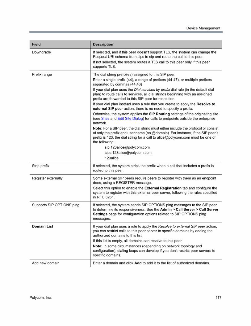
Device Management
Polycom, Inc. 117
Downgrade If selected, and if this peer doesn’t support TLS, the system can change the Request-URI schema from sips to sip and route the call to this peer.
If not selected, the system routes a TLS call to this peer only if this peer supports TLS.
Prefix range The dial string prefix(es) assigned to this SIP peer.
Enter a single prefix (44), a range of prefixes (44-47), or multiple prefixes separated by commas (44,46)
If your dial plan uses the Dial services by prefix dial rule (in the default dial plan) to route calls to services, all dial strings beginning with an assigned prefix are forwarded to this SIP peer for resolution.
If your dial plan instead uses a rule that you create to apply the Resolve to external SIP peer action, there is no need to specify a prefix.
Otherwise, the system applies the SIP Routing settings of the originating site (see Sites and Edit Site Dialog) for calls to endpoints outside the enterprise network.
Note: For a SIP peer, the dial string must either include the protocol or consist of only the prefix and user name (no @domain). For instance, if the SIP peer’s prefix is 123, the dial string for a call to [email protected] must be one of the following:
sips:[email protected]
123alice
Strip prefix If selected, the system strips the prefix when a call that includes a prefix is routed to this peer.
Register externally Some external SIP peers require peers to register with them as an endpoint does, using a REGISTER message.
Select this option to enable the External Registration tab and configure the system to register with this external peer server, following the rules specified in RFC 3261.
Supports SIP OPTIONS ping If selected, the system sends SIP OPTIONS ping messages to the SIP peer to determine its responsiveness. See the Admin > Call Server > Call Server Settings page for configuration options related to SIP OPTIONS ping messages.
Domain List If your dial plan uses a rule to apply the Resolve to external SIP peer action, you can restrict calls to this peer server to specific domains by adding the authorized domains to this list.
If this list is empty, all domains can resolve to this peer.
Note: In some circumstances (depending on network topology and configuration), dialing loops can develop if you don't restrict peer servers to specific domains.
Add new domain Enter a domain and click Add to add it to the list of authorized domains.
Field Description
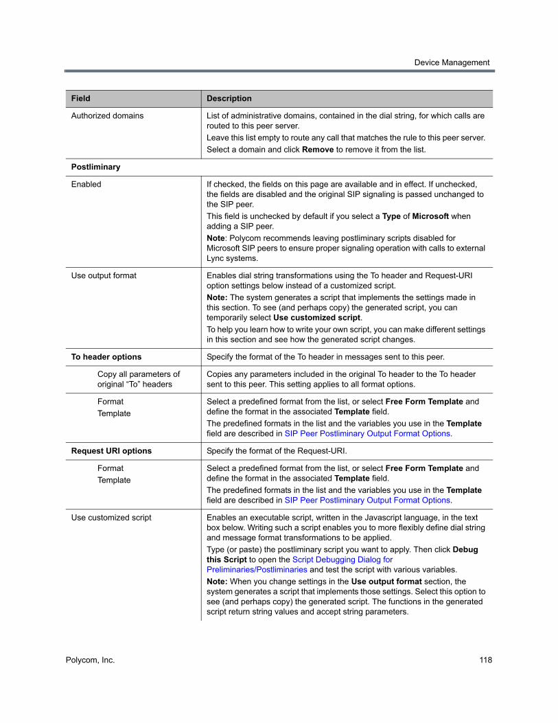
Device Management
Polycom, Inc. 118
Authorized domains List of administrative domains, contained in the dial string, for which calls are routed to this peer server.
Leave this list empty to route any call that matches the rule to this peer server.
Select a domain and click Remove to remove it from the list.
Postliminary
Enabled If checked, the fields on this page are available and in effect. If unchecked, the fields are disabled and the original SIP signaling is passed unchanged to the SIP peer.
This field is unchecked by default if you select a Type of Microsoft when adding a SIP peer.
Note: Polycom recommends leaving postliminary scripts disabled for Microsoft SIP peers to ensure proper signaling operation with calls to external Lync systems.
Use output format Enables dial string transformations using the To header and Request-URI option settings below instead of a customized script.
Note: The system generates a script that implements the settings made in this section. To see (and perhaps copy) the generated script, you can temporarily select Use customized script.
To help you learn how to write your own script, you can make different settings in this section and see how the generated script changes.
To header options Specify the format of the To header in messages sent to this peer.
Copy all parameters of original “To” headers
Copies any parameters included in the original To header to the To header sent to this peer. This setting applies to all format options.
Format
Template
Select a predefined format from the list, or select Free Form Template and define the format in the associated Template field.
The predefined formats in the list and the variables you use in the Template field are described in SIP Peer Postliminary Output Format Options.
Request URI options Specify the format of the Request-URI.
Format
Template
Select a predefined format from the list, or select Free Form Template and define the format in the associated Template field.
The predefined formats in the list and the variables you use in the Template field are described in SIP Peer Postliminary Output Format Options.
Use customized script Enables an executable script, written in the Javascript language, in the text box below. Writing such a script enables you to more flexibly define dial string and message format transformations to be applied.
Type (or paste) the postliminary script you want to apply. Then click Debug this Script to open the Script Debugging Dialog for Preliminaries/Postliminaries and test the script with various variables.
Note: When you change settings in the Use output format section, the system generates a script that implements those settings. Select this option to see (and perhaps copy) the generated script. The functions in the generated script return string values and accept string parameters.
Field Description
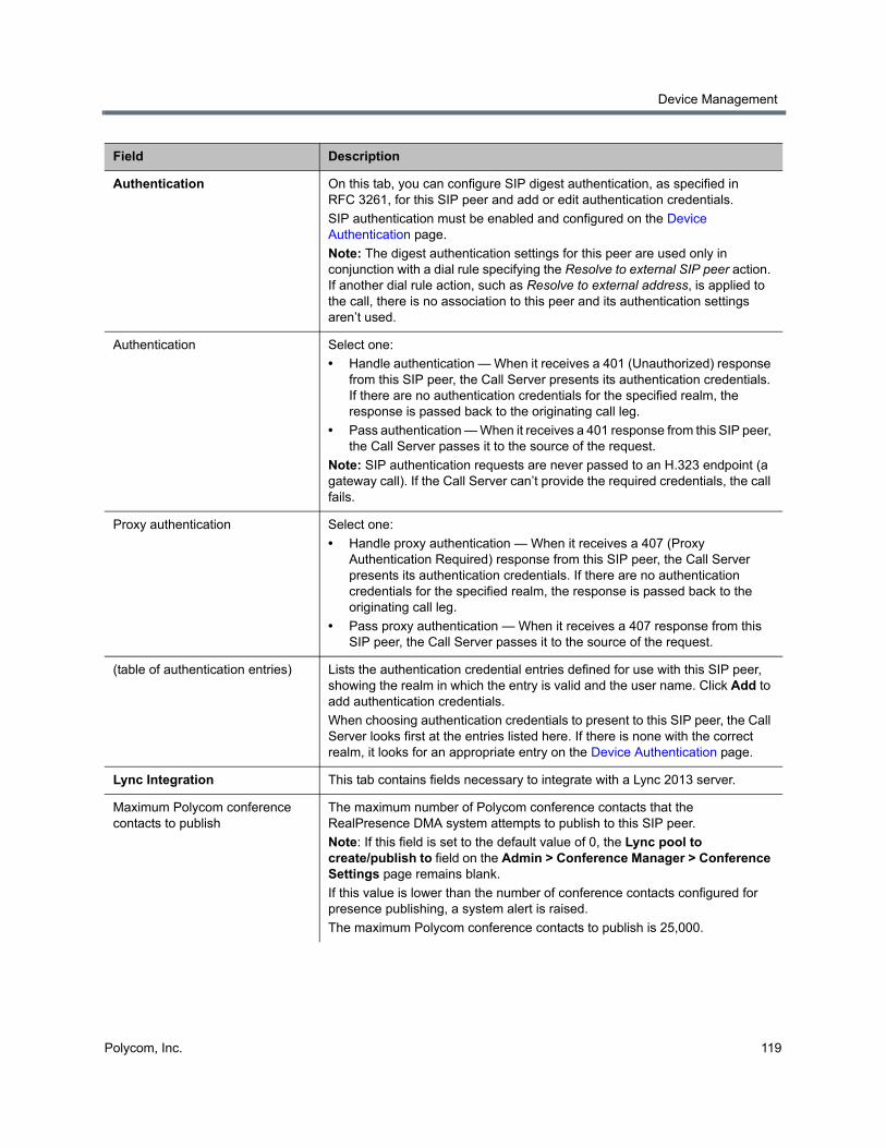
Device Management
Polycom, Inc. 119
Authentication On this tab, you can configure SIP digest authentication, as specified in RFC 3261, for this SIP peer and add or edit authentication credentials.
SIP authentication must be enabled and configured on the Device Authentication page.
Note: The digest authentication settings for this peer are used only in conjunction with a dial rule specifying the Resolve to external SIP peer action. If another dial rule action, such as Resolve to external address, is applied to the call, there is no association to this peer and its authentication settings aren’t used.
Authentication Select one:
• Handle authentication — When it receives a 401 (Unauthorized) response from this SIP peer, the Call Server presents its authentication credentials. If there are no authentication credentials for the specified realm, the response is passed back to the originating call leg.
• Pass authentication — When it receives a 401 response from this SIP peer, the Call Server passes it to the source of the request.
Note: SIP authentication requests are never passed to an H.323 endpoint (a gateway call). If the Call Server can’t provide the required credentials, the call fails.
Proxy authentication Select one:
• Handle proxy authentication — When it receives a 407 (Proxy Authentication Required) response from this SIP peer, the Call Server presents its authentication credentials. If there are no authentication credentials for the specified realm, the response is passed back to the originating call leg.
• Pass proxy authentication — When it receives a 407 response from this SIP peer, the Call Server passes it to the source of the request.
(table of authentication entries) Lists the authentication credential entries defined for use with this SIP peer, showing the realm in which the entry is valid and the user name. Click Add to add authentication credentials.
When choosing authentication credentials to present to this SIP peer, the Call Server looks first at the entries listed here. If there is none with the correct realm, it looks for an appropriate entry on the Device Authentication page.
Lync Integration This tab contains fields necessary to integrate with a Lync 2013 server.
Maximum Polycom conference contacts to publish
The maximum number of Polycom conference contacts that the RealPresence DMA system attempts to publish to this SIP peer.
Note: If this field is set to the default value of 0, the Lync pool to create/publish to field on the Admin > Conference Manager > Conference Settings page remains blank.
If this value is lower than the number of conference contacts configured for presence publishing, a system alert is raised.
The maximum Polycom conference contacts to publish is 25,000.
Field Description
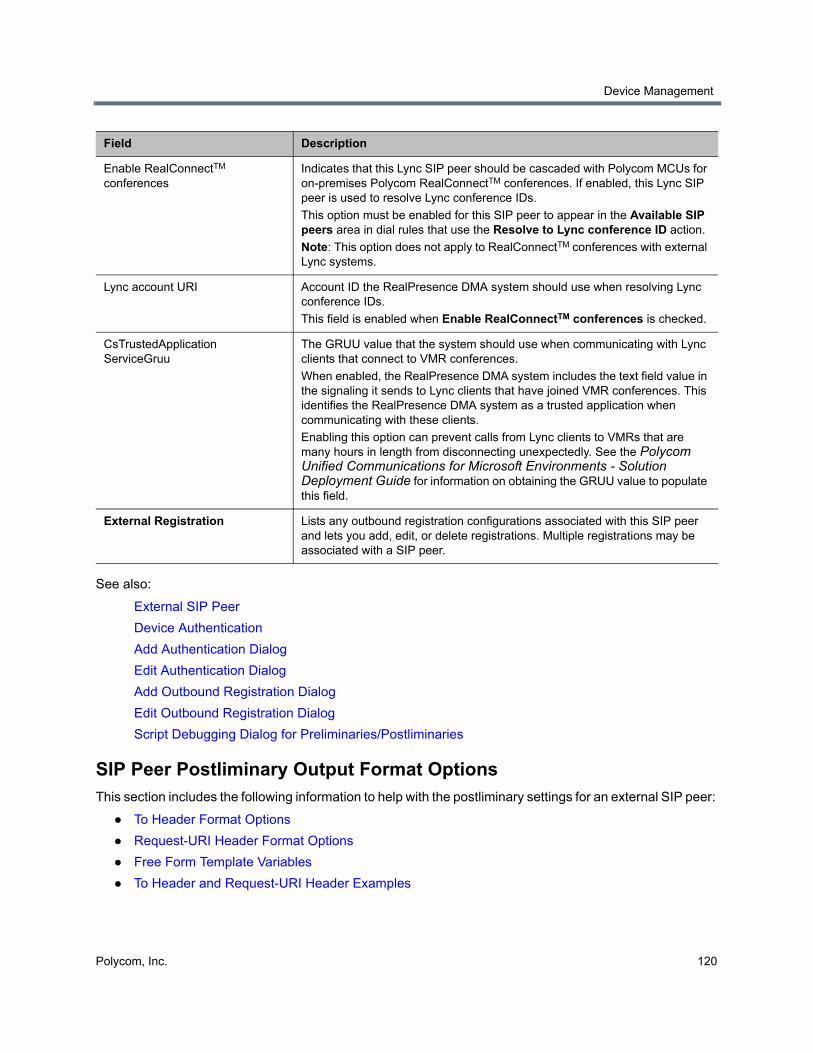
Device Management
Polycom, Inc. 120
See also:
External SIP Peer
Device Authentication
Add Authentication Dialog
Edit Authentication Dialog
Add Outbound Registration Dialog
Edit Outbound Registration Dialog
Script Debugging Dialog for Preliminaries/Postliminaries
SIP Peer Postliminary Output Format OptionsThis section includes the following information to help with the postliminary settings for an external SIP peer:
● To Header Format Options
● Request-URI Header Format Options
● Free Form Template Variables
● To Header and Request-URI Header Examples
Enable RealConnectTM conferences
Indicates that this Lync SIP peer should be cascaded with Polycom MCUs for on-premises Polycom RealConnectTM conferences. If enabled, this Lync SIP peer is used to resolve Lync conference IDs.
This option must be enabled for this SIP peer to appear in the Available SIP peers area in dial rules that use the Resolve to Lync conference ID action.
Note: This option does not apply to RealConnectTM conferences with external Lync systems.
Lync account URI Account ID the RealPresence DMA system should use when resolving Lync conference IDs.
This field is enabled when Enable RealConnectTM conferences is checked.
CsTrustedApplication ServiceGruu
The GRUU value that the system should use when communicating with Lync clients that connect to VMR conferences.
When enabled, the RealPresence DMA system includes the text field value in the signaling it sends to Lync clients that have joined VMR conferences. This identifies the RealPresence DMA system as a trusted application when communicating with these clients.
Enabling this option can prevent calls from Lync clients to VMRs that are many hours in length from disconnecting unexpectedly. See the Polycom Unified Communications for Microsoft Environments - Solution Deployment Guide for information on obtaining the GRUU value to populate this field.
External Registration Lists any outbound registration configurations associated with this SIP peer and lets you add, edit, or delete registrations. Multiple registrations may be associated with a SIP peer.
Field Description
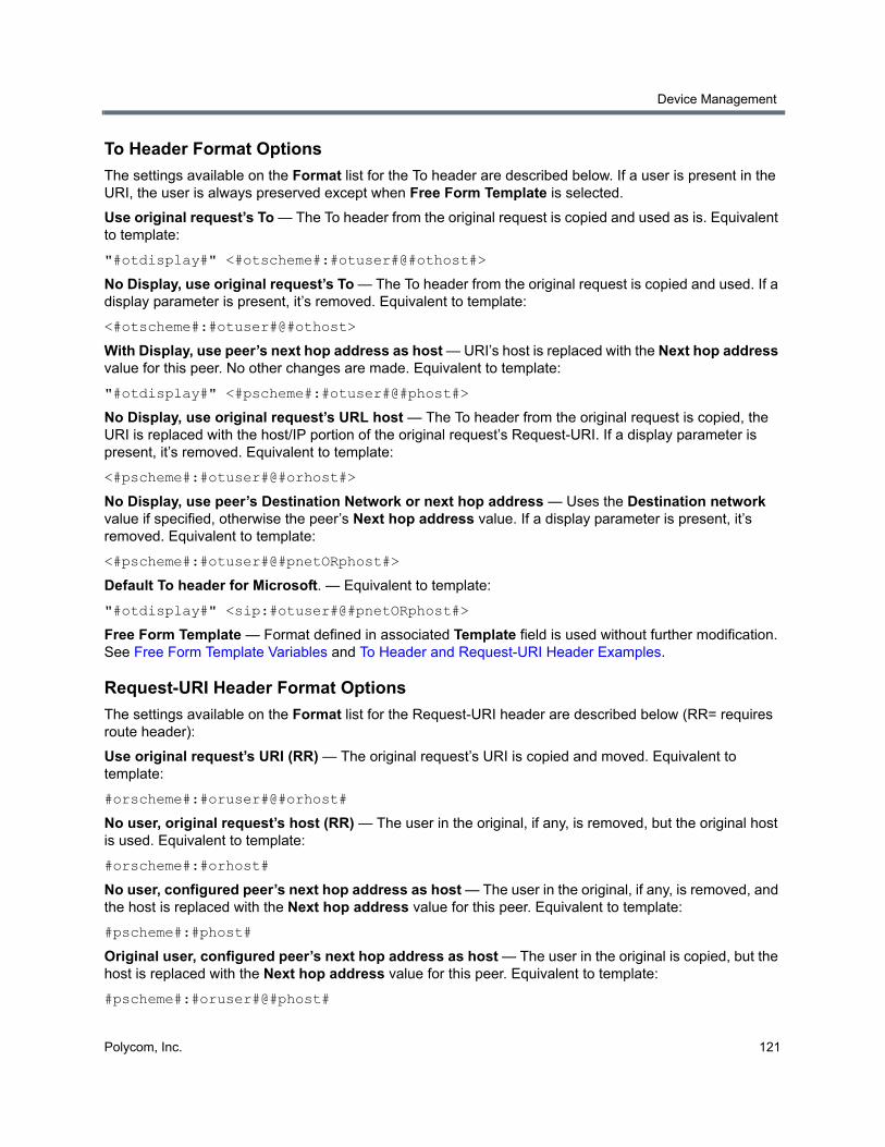
Device Management
Polycom, Inc. 121
To Header Format Options
The settings available on the Format list for the To header are described below. If a user is present in the URI, the user is always preserved except when Free Form Template is selected.
Use original request’s To — The To header from the original request is copied and used as is. Equivalent to template:
"#otdisplay#" <#otscheme#:#otuser#@#othost#>
No Display, use original request’s To — The To header from the original request is copied and used. If a display parameter is present, it’s removed. Equivalent to template:
<#otscheme#:#otuser#@#othost>
With Display, use peer’s next hop address as host — URI’s host is replaced with the Next hop address value for this peer. No other changes are made. Equivalent to template:
"#otdisplay#" <#pscheme#:#otuser#@#phost#>
No Display, use original request’s URL host — The To header from the original request is copied, the URI is replaced with the host/IP portion of the original request’s Request-URI. If a display parameter is present, it’s removed. Equivalent to template:
<#pscheme#:#otuser#@#orhost#>
No Display, use peer’s Destination Network or next hop address — Uses the Destination network value if specified, otherwise the peer’s Next hop address value. If a display parameter is present, it’s removed. Equivalent to template:
<#pscheme#:#otuser#@#pnetORphost#>
Default To header for Microsoft. — Equivalent to template:
"#otdisplay#" <sip:#otuser#@#pnetORphost#>
Free Form Template — Format defined in associated Template field is used without further modification. See Free Form Template Variables and To Header and Request-URI Header Examples.
Request-URI Header Format Options
The settings available on the Format list for the Request-URI header are described below (RR= requires route header):
Use original request’s URI (RR) — The original request’s URI is copied and moved. Equivalent to template:
#orscheme#:#oruser#@#orhost#
No user, original request’s host (RR) — The user in the original, if any, is removed, but the original host is used. Equivalent to template:
#orscheme#:#orhost#
No user, configured peer’s next hop address as host — The user in the original, if any, is removed, and the host is replaced with the Next hop address value for this peer. Equivalent to template:
#pscheme#:#phost#
Original user, configured peer’s next hop address as host — The user in the original is copied, but the host is replaced with the Next hop address value for this peer. Equivalent to template:
#pscheme#:#oruser#@#phost#
Device Management
Polycom, Inc. 122
Use user as host (RR) — Uses the user in the original, if specified, as the host value, otherwise the host value is used as is. Equivalent to template:
#orscheme#:#oruser# (but if no original user is present, the host value is used as is)
No user, configured peer’s Destination Network or next hop address — Uses the Destination network value if specified, otherwise the peer’s Next hop address value. Equivalent to template:
#pscheme#:#pnetORphost#
Original user, configured peer’s Destination Network or next hop address — Uses the user in the original, if specified, but replaces the host with the Destination network value, if specified, or the peer’s Next hop address value. Equivalent to template:
#pscheme#:#otuser#@#pnetORphost#
Default Request-URI for Microsoft — Equivalent to template:
sip:#oruser#@#pnetORphost#:#pport#;transport=#ptransport#
Request-URI for Microsoft without CSS — Equivalent to template:
sip:#phost#:#pport#;transport=#ptransport#
Free Form Template — Format defined in associated Template field is used without further modification. See Free Form Template Variables and To Header and Request-URI Header Examples.
Free Form Template Variables
In the Template fields on the Postliminary tab, and when specifying a Request-URI or other headers for outbound registration (see Add Outbound Registration Dialog), you can use the variables in the following table entered as #variable name# (case insensitive). The system replaces the variables with the corresponding values as shown below.
You can also use these variables (without # delimiters) in a customized script.
Note: SIP peers and TLS
If the peer’s transport type is configured as TLS, this setting makes the Request-URI scheme sips even if the original Request-URI’s scheme was sip. Some SIP peers, such as the Cisco SBC, won't accept sips in the Request-URI if other headers contain sip. If this problem exists, change Format to Free Form Template and in the Template field, change #pscheme# to #orscheme#.
Variable Description
otdisplay Original To header's display name.
otuser User portion of the original request's To header URL field.
othost Host/IP portion of the original request's To header URL field.
otscheme Original To header's URL scheme (sip, sips, tel).
phost Peer's configured IP/FQDN (next hop address).
pscheme Peer's configured scheme based on transport (sip, sips).
oruser User portion of the original request's Request-URL field.

Device Management
Polycom, Inc. 123
In addition to the variables, you can enter any values acceptable for the Request-URI or To header.
For the Request-URI, the contents of the Template field specify only the URI portion of the full Request line. Depending on network configuration, a Route header may be required.
For the To header, the contents of the Template field specify the complete header except for the header name (“To”).
The @ symbol is always removed if no user is present in the result.
To Header and Request-URI Header Examples
The tables below show some examples of To header and Request-URI header transformations using the variables described in Free Form Template Variables.
orhost Host/IP portion of the original request's Request-URL field.
orscheme Original request's URL scheme.
pnetORphost Destination network parameter if specified, otherwise the peer's configured IP/FQDN.
pport The port specified for this SIP peer.
ptransport The transport type specified for this SIP peer.
Original To Header Template Result
sip:user@host #orscheme#:atest sip:atest
sip:user@host #orscheme#:#oruser#@#orhost# sip:user@host
sip:host #orscheme#:#oruser#@foo.bar sip:foo.bar
sip:user@host #orscheme#:#oruser#@foo.bar sip:[email protected]
sip:host sips:#oruser#@foo.bar sips:foo.bar
sip:user@host #orscheme#:#oruser#@#othost# sip:user@toHeaderUrlHost
Original Request-URI Header Template Result
displayname <sip:user@host>
#otdisplay# <sip:#otuser#@#othost#>
displayname <sip:user@host>
displayname <sip:user@host>
<#otscheme#:#otuser#@#othost#> <sip:user@host>
displayname <sip:user@host>
<sip:#otuser#@#othost#> <sip:user@host>
Variable Description
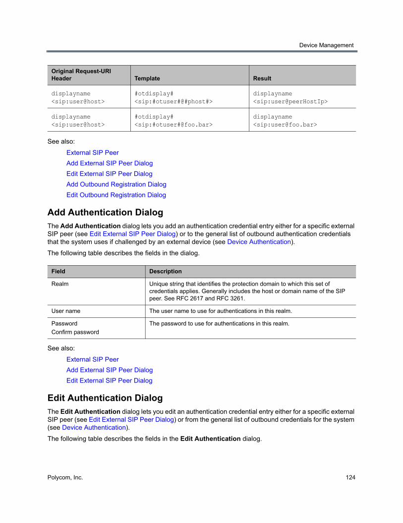
Device Management
Polycom, Inc. 124
See also:
External SIP Peer
Add External SIP Peer Dialog
Edit External SIP Peer Dialog
Add Outbound Registration Dialog
Edit Outbound Registration Dialog
Add Authentication DialogThe Add Authentication dialog lets you add an authentication credential entry either for a specific external SIP peer (see Edit External SIP Peer Dialog) or to the general list of outbound authentication credentials that the system uses if challenged by an external device (see Device Authentication).
The following table describes the fields in the dialog.
See also:
External SIP Peer
Add External SIP Peer Dialog
Edit External SIP Peer Dialog
Edit Authentication DialogThe Edit Authentication dialog lets you edit an authentication credential entry either for a specific external SIP peer (see Edit External SIP Peer Dialog) or from the general list of outbound credentials for the system (see Device Authentication).
The following table describes the fields in the Edit Authentication dialog.
displayname <sip:user@host>
#otdisplay# <sip:#otuser#@#phost#>
displayname <sip:user@peerHostIp>
displayname <sip:user@host>
#otdisplay# <sip:#otuser#@foo.bar>
displayname <sip:[email protected]>
Field Description
Realm Unique string that identifies the protection domain to which this set of credentials applies. Generally includes the host or domain name of the SIP peer. See RFC 2617 and RFC 3261.
User name The user name to use for authentications in this realm.
Password
Confirm password
The password to use for authentications in this realm.
Original Request-URI Header Template Result
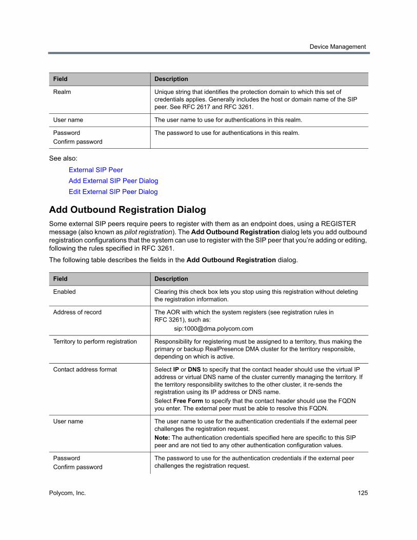
Device Management
Polycom, Inc. 125
See also:
External SIP Peer
Add External SIP Peer Dialog
Edit External SIP Peer Dialog
Add Outbound Registration DialogSome external SIP peers require peers to register with them as an endpoint does, using a REGISTER message (also known as pilot registration). The Add Outbound Registration dialog lets you add outbound registration configurations that the system can use to register with the SIP peer that you’re adding or editing, following the rules specified in RFC 3261.
The following table describes the fields in the Add Outbound Registration dialog.
Field Description
Realm Unique string that identifies the protection domain to which this set of credentials applies. Generally includes the host or domain name of the SIP peer. See RFC 2617 and RFC 3261.
User name The user name to use for authentications in this realm.
Password
Confirm password
The password to use for authentications in this realm.
Field Description
Enabled Clearing this check box lets you stop using this registration without deleting the registration information.
Address of record The AOR with which the system registers (see registration rules in RFC 3261), such as:
Territory to perform registration Responsibility for registering must be assigned to a territory, thus making the primary or backup RealPresence DMA cluster for the territory responsible, depending on which is active.
Contact address format Select IP or DNS to specify that the contact header should use the virtual IP address or virtual DNS name of the cluster currently managing the territory. If the territory responsibility switches to the other cluster, it re-sends the registration using its IP address or DNS name.
Select Free Form to specify that the contact header should use the FQDN you enter. The external peer must be able to resolve this FQDN.
User name The user name to use for the authentication credentials if the external peer challenges the registration request.
Note: The authentication credentials specified here are specific to this SIP peer and are not tied to any other authentication configuration values.
Password
Confirm password
The password to use for the authentication credentials if the external peer challenges the registration request.

Device Management
Polycom, Inc. 126
See also:
External SIP Peer
Add External SIP Peer Dialog
Edit External SIP Peer Dialog
Edit Outbound Registration DialogSome external SIP peers require peer proxies to register with them as an endpoint does, using a REGISTER message. The Edit Outbound Registration dialog lets you edit the selected outbound registration configuration.
The following table describes the fields in the Edit Outbound Registration dialog.
Request-URI The Request-URI to include when registering with this SIP peer, specified using the variables (#delimited) defined in Free Form Template Variables.
Other headers Additional headers to include when registering with this SIP peer.
Click Add to add a header. In the Add Header dialog, specify the header name and value(s), using the variables (#delimited) defined in Free Form Template Variables.
Click Edit or Delete to edit or delete the selected header.
Field Description
Enabled Clearing this check box lets you stop using this registration without deleting the registration information.
Address of record The AOR with which the system registers (see registration rules in RFC 3261), such as:
Territory to perform registration Responsibility for registering must be assigned to a territory, thus making the primary or backup RealPresence DMA cluster for the territory responsible, depending on which is active.
Contact address format Select IP or DNS to specify that the contact header should use the virtual IP address or virtual DNS name of the cluster currently managing the territory. If the territory responsibility switches to the other cluster, it re-sends the registration using its IP address or DNS name.
Select Free Form to specify that the contact header should use the FQDN you enter. The external peer must be able to resolve this FQDN.
User name The user name to use for the authentication credentials if the external peer challenges the registration request.
Note: The authentication credentials specified here are specific to this SIP peer and are not tied to any other authentication configuration values.
Password
Confirm password
The password to use for the authentication credentials if the external peer challenges the registration request.
Field Description
Device Management
Polycom, Inc. 127
See also:
External SIP Peer
Add External SIP Peer Dialog
Edit External SIP Peer Dialog
External H.323 SBCOn the External H.323 SBC page, you can add or remove H.323 SBCs (session border controllers) that the system can use to reach endpoints outside the enterprise network via prefix-based dialing (Polycom VBP appliances are supported). In an H.323 environment, H.323 SBCs regulate access across the firewall.
This is a supercluster-wide configuration.
There are three reasons to configure an H.323 SBC on the External H.323 SBC page:
● To create a prefix service that allows dialing through the specific SBC by prefix. An SBC configured on this page must have a prefix or prefix range assigned to it and can only be reached by dialing its prefix(es).
● To define a postliminary script to be applied when dialing through the specific SBC.
● For bandwidth management.
The Polycom RealPresence DMA system is capable of performing call admission control (CAC) while processing an LRQ from a neighbor gatekeeper. This allows the system to reject the call for resource or policy reasons early in the setup process (in response to the LRQ), rather than waiting until later in the call setup.
In order to perform early CAC, the Polycom RealPresence DMA system must know the caller’s media address, which isn’t provided in the LRQ and is unknowable for an ordinary gatekeeper. If the gatekeeper is also an SBC, however, it proxies the media. The Polycom RealPresence DMA system
Request-URI The Request-URI to include when registering with this SIP peer, specified using the variables (#delimited) defined in Free Form Template Variables.
Other headers Additional headers to include when registering with this SIP peer.
Click Add to add a header. In the Add Header dialog, specify the header name and value(s), using the variables (#delimited) defined in Free Form Template Variables.
Click Edit or Delete to edit or delete the selected header.
Note: SBC configuration
Only H.323 SBCs are added to the External H.323 SBC page. SIP SBCs are configured as SIP peers (see External SIP Peer) and/or on a per-site basis (see Edit Site Dialog).
H.323 SBCs that are added to the External H.323 SBC page are reached by prefix-based dialing (rule 4 of the default dial plan; see The Default Dial Plan and Suggestions for Modifications).
SBCs to be reached by a dial rule using the Resolve to IP address action (rule 6 of the default dial plan) are configured on a per-site basis (see Edit Site Dialog).
In general, H.323 SBCs should be configured on a per-site basis, so that calls to endpoints outside the enterprise network are routed to the SBC assigned to the originating site.
Field Description
Device Management
Polycom, Inc. 128
can assume that its media address is the same as its signaling address, and proceed with early CAC. The Polycom RealPresence DMA system performs early CAC only in response to LRQs received from SBCs configured on the External H.323 SBC page.
The following table describes the fields in the list.
See also:
Device Management
Edit External H.323 SBC Dialog
Add External H.323 SBC DialogThe following table describes the fields in the Add External H.323 SBC dialog.
Column Description
Name The name of the SBC.
Description Brief description of the SBC.
Address Host name or IP address of the SBC.
Prefix Range The dial string prefix(es) assigned to this SBC.
If your dial plan uses the Dial services by prefix dial rule (in the default dial plan) to route calls to services, all dial strings beginning with an assigned prefix are forwarded to this SBC for resolution.
Enabled Indicates whether the system is using the SBC.
Note: SBC configuration
Only H.323 SBCs are added to the External H.323 SBC page. SIP SBCs are configured as SIP peers (see External SIP Peer) and/or on a per-site basis (see Edit Site Dialog).
H.323 SBCs that are added to the External H.323 SBC page are reached by prefix-based dialing (rule 4 of the default dial plan; see The Default Dial Plan and Suggestions for Modifications).
SBCs to be reached by a dial rule using the Resolve to IP address action (rule 6 of the default dial plan) are configured on a per-site basis (see Edit Site Dialog).
In general, H.323 SBCs should be configured on a per-site basis, so that calls to endpoints outside the enterprise network are routed to the SBC assigned to the originating site.
Column Description
External H.323 SBC
Enabled Clearing this check box lets you stop using an external SBC without deleting it.
Name SBC unit name.
Description The text description displayed in the External H.323 SBC list.
Address Host name or IP address of the SBC.
Device Management
Polycom, Inc. 129
See also:
External H.323 SBC
Script Debugging Dialog for Preliminaries/Postliminaries
Edit External H.323 SBC DialogThe following table describes the fields in the Edit External H.323 SBC dialog.
Port The SBC’s port number. Leave set to 1720 unless you know the unit is using a non-standard port number.
Prefix range The dial string prefix or prefix range assigned to this SBC. Required.
Enter a single prefix (44), a range of prefixes (44-47), or multiple prefixes separated by commas (44,46)
The Dial services by prefix dial rule in the default dial plan routes calls to the assigned prefix(es) to this SBC for resolution.
Strip prefix If selected, the system strips the prefix when a call that includes a prefix is routed to this SBC.
Postliminary A postliminary is an executable script, written in the Javascript language, that defines dial string transformations to be applied before querying the SBC.
Enabled Lets you turn a postliminary on or off without deleting it.
Script Type (or paste) the postliminary script you want to apply. Then click Debug this Script to open the Script Debugging Dialog for Preliminaries/Postliminaries and test the script with various variables.
Note: SBC configuration
Only H.323 SBCs are added to the External H.323 SBC page. SIP SBCs are configured as SIP peers (see External SIP Peer) and/or on a per-site basis (see Edit Site Dialog).
H.323 SBCs that are added to the External H.323 SBC page are reached by prefix-based dialing (rule 4 of the default dial plan; see The Default Dial Plan and Suggestions for Modifications).
SBCs to be reached by a dial rule using the Resolve to IP address action (rule 6 of the default dial plan) are configured on a per-site basis (see Edit Site Dialog).
In general, H.323 SBCs should be configured on a per-site basis, so that calls to endpoints outside the enterprise network are routed to the SBC assigned to the originating site.
Column Description
External H.323 SBC
Enabled Clearing this check box lets you stop using an external SBC without deleting it.
Name SBC unit name.
Description The text description displayed in the External H.323 SBC list.
Column Description
Device Management
Polycom, Inc. 130
See also:
External H.323 SBC
Script Debugging Dialog for Preliminaries/Postliminaries
Address Host name or IP address of the SBC.
Port The SBC’s port number. Leave set to 1720 unless you know the unit is using a non-standard port number.
Prefix range The dial string prefix or prefix range assigned to this SBC. Required.
Enter a single prefix (44), a range of prefixes (44-47), or multiple prefixes separated by commas (44,46)
The Dial services by prefix dial rule in the default dial plan routes calls to the assigned prefix(es) to this SBC for resolution.
Strip prefix If selected, the system strips the prefix when a call that includes a prefix is routed to this SBC.
Postliminary A postliminary is an executable script, written in the Javascript language, that defines dial string transformations to be applied before querying the SBC.
Enabled Lets you turn a postliminary on or off without deleting it.
Script Type (or paste) the postliminary script you want to apply. Then click Debug this Script to open the Script Debugging Dialog for Preliminaries/Postliminaries and test the script with various variables.
Column Description
Polycom, Inc. 131
MCU Management
This section describes the Polycom® RealPresence® Distributed Media Application™ (DMA®) 7000 system’s MCU management tools and tasks:
● MCUs
● MCU Pools
● MCU Pool Orders
MCUsThe MCUs page shows the MCUs, or media servers, known to the Polycom RealPresence DMA system. In a superclustered system, this list encompasses all MCUs throughout the supercluster and is the same on all clusters in the supercluster. It includes:
● MCUs that are available as a conferencing resource for the Polycom RealPresence DMA system’s Conference Manager (enabled for conference rooms), but aren’t registered with the Call Server. Up to 64 MCUs can be enabled for conference rooms (virtual meeting rooms, or VMRs).
● MCUs that are registered with the Polycom RealPresence DMA system’s Call Server as standalone MCUs and/or ISDN gateways, but aren’t available to the Conference Manager as conferencing resources.
● MCUs that are both registered with the Call Server and available to the Conference Manager as conferencing resources.
An MCU can appear in this list either because it registered with the Call Server or because it was manually added. If the MCU registered itself, it can be used as a standalone MCU. But in order for Conference Manager to use such an MCU as a conferencing resource, you must edit its entry to enable it for conference rooms and provide the additional configuration information required.
You must organize MCUs configured as conferencing resources into one or more MCU pools (logical groupings of media servers). Then, you can define one or more MCU pool orders that specify the order of preference in which MCU pools are used.
Every conference room (VMR) is associated with an MCU pool order. The pool(s) to which an MCU belongs, and the pool order(s) to which a pool belongs, are used to determine which MCU is used to host a conference. See MCU Pools and MCU Pool Orders.
MCU Management
Polycom, Inc. 132
Note: RealPresence Resource Manager integration and MCU pools
If you have a Polycom RealPresence Resource Manager system that uses the RealPresence DMA system API to schedule conferences on the RealPresence DMA system’s conferencing resources (MCU pools), you must create MCU pools and pool orders specifically for the use of the RealPresence Resource Manager system. The pool orders should be named in such a way that:
• They appear at the top of the pool order list presented in the RealPresence Resource Manager system.
• Users of that system will understand that they should choose one of those pool orders.
When adding an MCU for use by a RealPresence Resource Manager system, the option Enable for conference rooms should not be selected in the settings dialog for that MCU.
Note: MCUs and ISDN gateway selection
MCU pools and pool orders are not used to select an ISDN gateway for simplified gateway dialing. See ISDN Gateway Selection Process.
When a Polycom RealPresence Collaboration Server or RMX MCU is functioning as an ISDN gateway, each call through the gateway consumes two ports, one for the ISDN side and one for the H.323 side. The ports used for gateway calls aren’t available for conferences, so gateway operations may significantly reduce the available conferencing resources.
Note: MCU support
The Polycom RealPresence DMA system supports the use of Cisco Codian 4200, 4500, and MSE 8000 series MCUs as part of the Conference Manager’s conferencing resource pool, but their Media Port Reservation feature is not supported. This feature must be set to Disabled on Cisco Codian MCUs in order to use them as part of the Conference Manager’s conferencing resource pool.
The Polycom RealPresence DMA system supports the use of Polycom MGC MCUs, but not as part of the Conference Manager’s conferencing resource pool. They can register with the Call Server as standalone MCUs (dialed by IP or prefix) and/or ISDN gateways. Their model designation is Polycom MGC gateway, even if being used as standalone MCUs.
Note: MCU connections
In order to efficiently manage multiple calls as quickly as possible, the Polycom RealPresence DMA system uses multiple connections per MCU. By default, a RealPresence Collaboration Server or RMX MCU allows up to 20 connections per user. We recommend not reducing this setting (the MAX_NUMBER_OF_MANAGEMENT_SESSIONS_PER_USER system flag). If you have a RealPresence DMA supercluster with three Conference Manager clusters and a busy conferencing environment, we recommend increasing this value to 30.
MCU Management
Polycom, Inc. 133
Considerations when using MCUs with the RealPresence DMA systemIn high security mode, the RealPresence DMA system uses only HTTPS for the conference control connection to MCUs, and you must configure your MCUs to accept encrypted connections. We recommend doing so. When unencrypted connections are used, the MCU login name and password are sent unencrypted over the network.
The Polycom RealPresence DMA system knows only what resources an MCU has currently available. It can’t know what’s been scheduled for future use.
The Automatic Password Generation feature, introduced in RMX version 7.0.2, is not compatible with the Polycom RealPresence DMA system. On Polycom MCUs to be used with the Polycom RealPresence DMA system, disable this feature by setting the system flags NUMERIC_CONF_PASS_DEFAULT_LEN and NUMERIC_CHAIR_PASS_DEFAULT_LEN both to 0 (zero).
The following table describes the fields in the list on the Network > MCU > MCUs page. To view this information in a more readable form for a selected MCU, click the View Details command in the Actions list.
Note: Bandwidth management requires MCU registration
For H.323 calls to a conference room (virtual meeting room, or VMR), the RealPresence DMA system can only do bandwidth management if the MCU is registered with it (in a supercluster, registered with any cluster). If the MCU is unregistered or registered to another gatekeeper (not part of the supercluster), the bandwidth for the call is not counted for bandwidth management, site statistics, or the network usage report.
In a SIP signaling environment, in order for a Polycom RealPresence Collaboration Server or RMX MCU to register with the RealPresence DMA system’s Call Server, two system flags on the MCU must be set properly:
• Set the MS_ENVIRONMENT flag to NO.
• Make sure the SIP_REGISTER_ONLY_ONCE flag is set to NO or not present.
In order for the Polycom RealPresence DMA system to assign an alternate gatekeeper to an MCU, the MCU must be in a territory that has a backup RealPresence DMA system assigned to it.
Note: Resource usage reporting
The RealPresence DMA system reports port counts based on resource usage for CIF calls. Version 8.1 and later Polycom MCUs report port counts based on resource usage for HD720p30 calls. In general, 3 CIF = 1 HD720p30, but it varies depending on bridge/card type and other factors.
See your Polycom RealPresence Collaboration Server or RMX system documentation for more detailed information about resource usage.
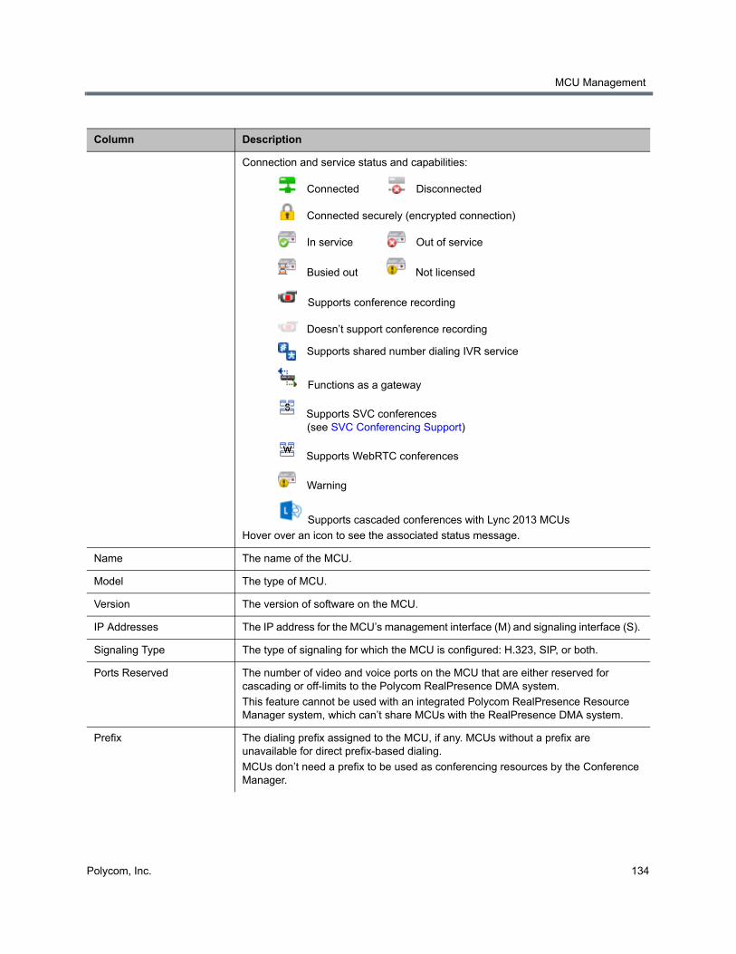
MCU Management
Polycom, Inc. 134
Column Description
Connection and service status and capabilities:
Connected Disconnected
Connected securely (encrypted connection)
In service Out of service
Busied out Not licensed
Supports conference recording
Doesn’t support conference recording
Supports shared number dialing IVR service
Functions as a gateway
Supports SVC conferences (see SVC Conferencing Support)
Supports WebRTC conferences
Warning
Supports cascaded conferences with Lync 2013 MCUs
Hover over an icon to see the associated status message.
Name The name of the MCU.
Model The type of MCU.
Version The version of software on the MCU.
IP Addresses The IP address for the MCU’s management interface (M) and signaling interface (S).
Signaling Type The type of signaling for which the MCU is configured: H.323, SIP, or both.
Ports Reserved The number of video and voice ports on the MCU that are either reserved for cascading or off-limits to the Polycom RealPresence DMA system.
This feature cannot be used with an integrated Polycom RealPresence Resource Manager system, which can’t share MCUs with the RealPresence DMA system.
Prefix The dialing prefix assigned to the MCU, if any. MCUs without a prefix are unavailable for direct prefix-based dialing.
MCUs don’t need a prefix to be used as conferencing resources by the Conference Manager.
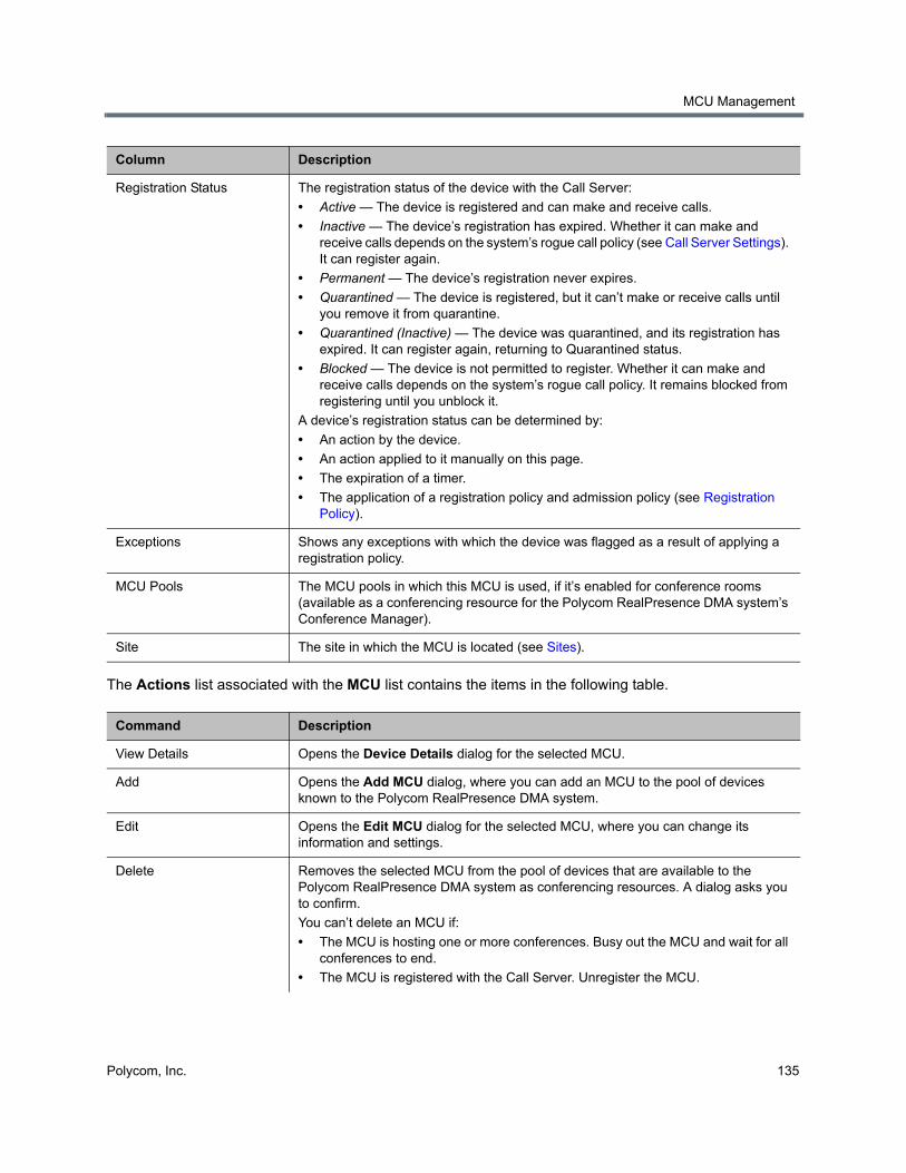
MCU Management
Polycom, Inc. 135
The Actions list associated with the MCU list contains the items in the following table.
Registration Status The registration status of the device with the Call Server:
• Active — The device is registered and can make and receive calls.
• Inactive — The device’s registration has expired. Whether it can make and receive calls depends on the system’s rogue call policy (see Call Server Settings). It can register again.
• Permanent — The device’s registration never expires.
• Quarantined — The device is registered, but it can’t make or receive calls until you remove it from quarantine.
• Quarantined (Inactive) — The device was quarantined, and its registration has expired. It can register again, returning to Quarantined status.
• Blocked — The device is not permitted to register. Whether it can make and receive calls depends on the system’s rogue call policy. It remains blocked from registering until you unblock it.
A device’s registration status can be determined by:
• An action by the device.
• An action applied to it manually on this page.
• The expiration of a timer.
• The application of a registration policy and admission policy (see Registration Policy).
Exceptions Shows any exceptions with which the device was flagged as a result of applying a registration policy.
MCU Pools The MCU pools in which this MCU is used, if it’s enabled for conference rooms (available as a conferencing resource for the Polycom RealPresence DMA system’s Conference Manager).
Site The site in which the MCU is located (see Sites).
Command Description
View Details Opens the Device Details dialog for the selected MCU.
Add Opens the Add MCU dialog, where you can add an MCU to the pool of devices known to the Polycom RealPresence DMA system.
Edit Opens the Edit MCU dialog for the selected MCU, where you can change its information and settings.
Delete Removes the selected MCU from the pool of devices that are available to the Polycom RealPresence DMA system as conferencing resources. A dialog asks you to confirm.
You can’t delete an MCU if:
• The MCU is hosting one or more conferences. Busy out the MCU and wait for all conferences to end.
• The MCU is registered with the Call Server. Unregister the MCU.
Column Description
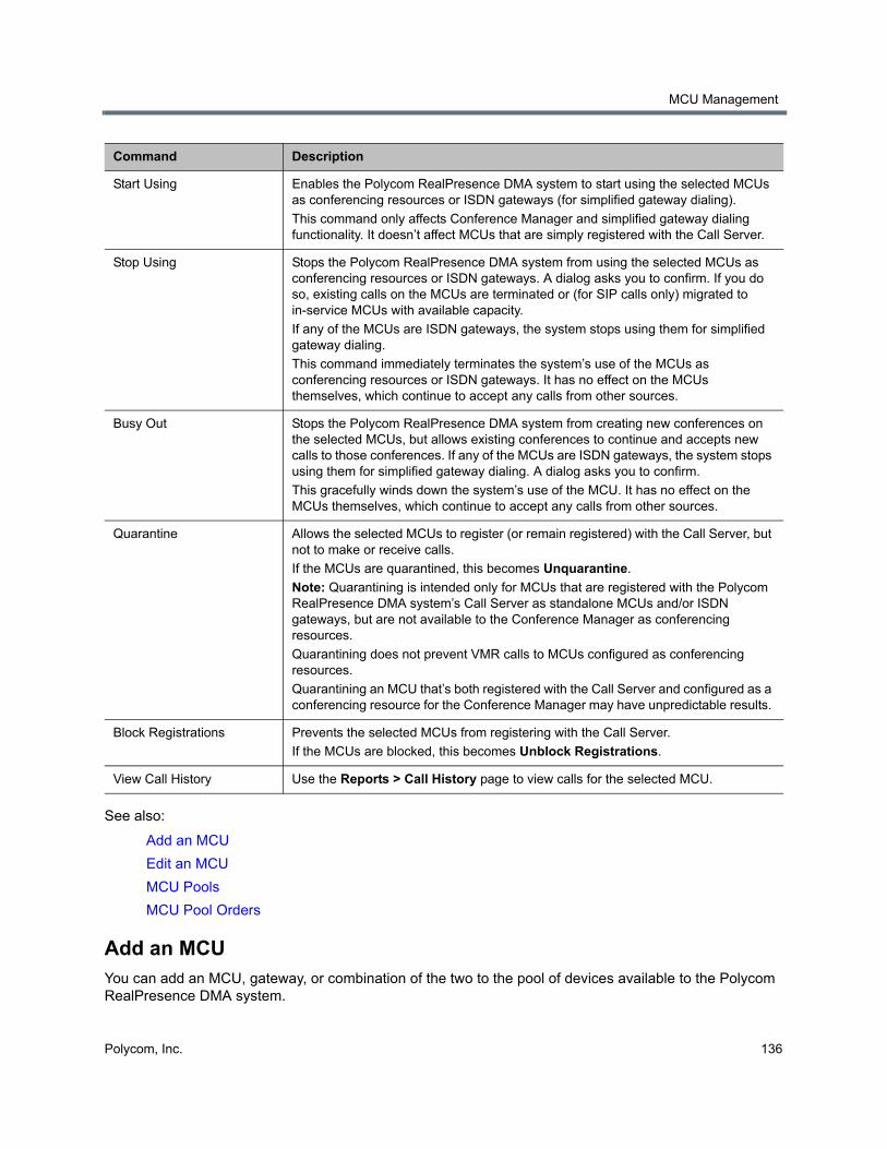
MCU Management
Polycom, Inc. 136
See also:
Add an MCU
Edit an MCU
MCU Pools
MCU Pool Orders
Add an MCUYou can add an MCU, gateway, or combination of the two to the pool of devices available to the Polycom RealPresence DMA system.
Start Using Enables the Polycom RealPresence DMA system to start using the selected MCUs as conferencing resources or ISDN gateways (for simplified gateway dialing).
This command only affects Conference Manager and simplified gateway dialing functionality. It doesn’t affect MCUs that are simply registered with the Call Server.
Stop Using Stops the Polycom RealPresence DMA system from using the selected MCUs as conferencing resources or ISDN gateways. A dialog asks you to confirm. If you do so, existing calls on the MCUs are terminated or (for SIP calls only) migrated to in-service MCUs with available capacity.
If any of the MCUs are ISDN gateways, the system stops using them for simplified gateway dialing.
This command immediately terminates the system’s use of the MCUs as conferencing resources or ISDN gateways. It has no effect on the MCUs themselves, which continue to accept any calls from other sources.
Busy Out Stops the Polycom RealPresence DMA system from creating new conferences on the selected MCUs, but allows existing conferences to continue and accepts new calls to those conferences. If any of the MCUs are ISDN gateways, the system stops using them for simplified gateway dialing. A dialog asks you to confirm.
This gracefully winds down the system’s use of the MCU. It has no effect on the MCUs themselves, which continue to accept any calls from other sources.
Quarantine Allows the selected MCUs to register (or remain registered) with the Call Server, but not to make or receive calls.
If the MCUs are quarantined, this becomes Unquarantine.
Note: Quarantining is intended only for MCUs that are registered with the Polycom RealPresence DMA system’s Call Server as standalone MCUs and/or ISDN gateways, but are not available to the Conference Manager as conferencing resources.
Quarantining does not prevent VMR calls to MCUs configured as conferencing resources.
Quarantining an MCU that’s both registered with the Call Server and configured as a conferencing resource for the Conference Manager may have unpredictable results.
Block Registrations Prevents the selected MCUs from registering with the Call Server.
If the MCUs are blocked, this becomes Unblock Registrations.
View Call History Use the Reports > Call History page to view calls for the selected MCU.
Command Description
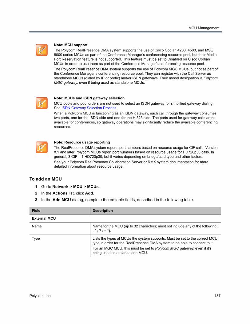
MCU Management
Polycom, Inc. 137
To add an MCU
1 Go to Network > MCU > MCUs.
2 In the Actions list, click Add.
3 In the Add MCU dialog, complete the editable fields, described in the following table.
Note: MCU support
The Polycom RealPresence DMA system supports the use of Cisco Codian 4200, 4500, and MSE 8000 series MCUs as part of the Conference Manager’s conferencing resource pool, but their Media Port Reservation feature is not supported. This feature must be set to Disabled on Cisco Codian MCUs in order to use them as part of the Conference Manager’s conferencing resource pool.
The Polycom RealPresence DMA system supports the use of Polycom MGC MCUs, but not as part of the Conference Manager’s conferencing resource pool. They can register with the Call Server as standalone MCUs (dialed by IP or prefix) and/or ISDN gateways. Their model designation is Polycom MGC gateway, even if being used as standalone MCUs.
Note: MCUs and ISDN gateway selection
MCU pools and pool orders are not used to select an ISDN gateway for simplified gateway dialing. See ISDN Gateway Selection Process.
When a Polycom MCU is functioning as an ISDN gateway, each call through the gateway consumes two ports, one for the ISDN side and one for the H.323 side. The ports used for gateway calls aren’t available for conferences, so gateway operations may significantly reduce the available conferencing resources.
Note: Resource usage reporting
The RealPresence DMA system reports port numbers based on resource usage for CIF calls. Version 8.1 and later Polycom MCUs report port numbers based on resource usage for HD720p30 calls. In general, 3 CIF = 1 HD720p30, but it varies depending on bridge/card type and other factors.
See your Polycom RealPresence Collaboration Server or RMX system documentation for more detailed information about resource usage.
Field Description
External MCU
Name Name for the MCU (up to 32 characters; must not include any of the following: , " ; ? : = *).
Type Lists the types of MCUs the system supports. Must be set to the correct MCU type in order for the RealPresence DMA system to be able to connect to it.
For an MGC MCU, this must be set to Polycom MGC gateway, even if it’s being used as a standalone MCU.
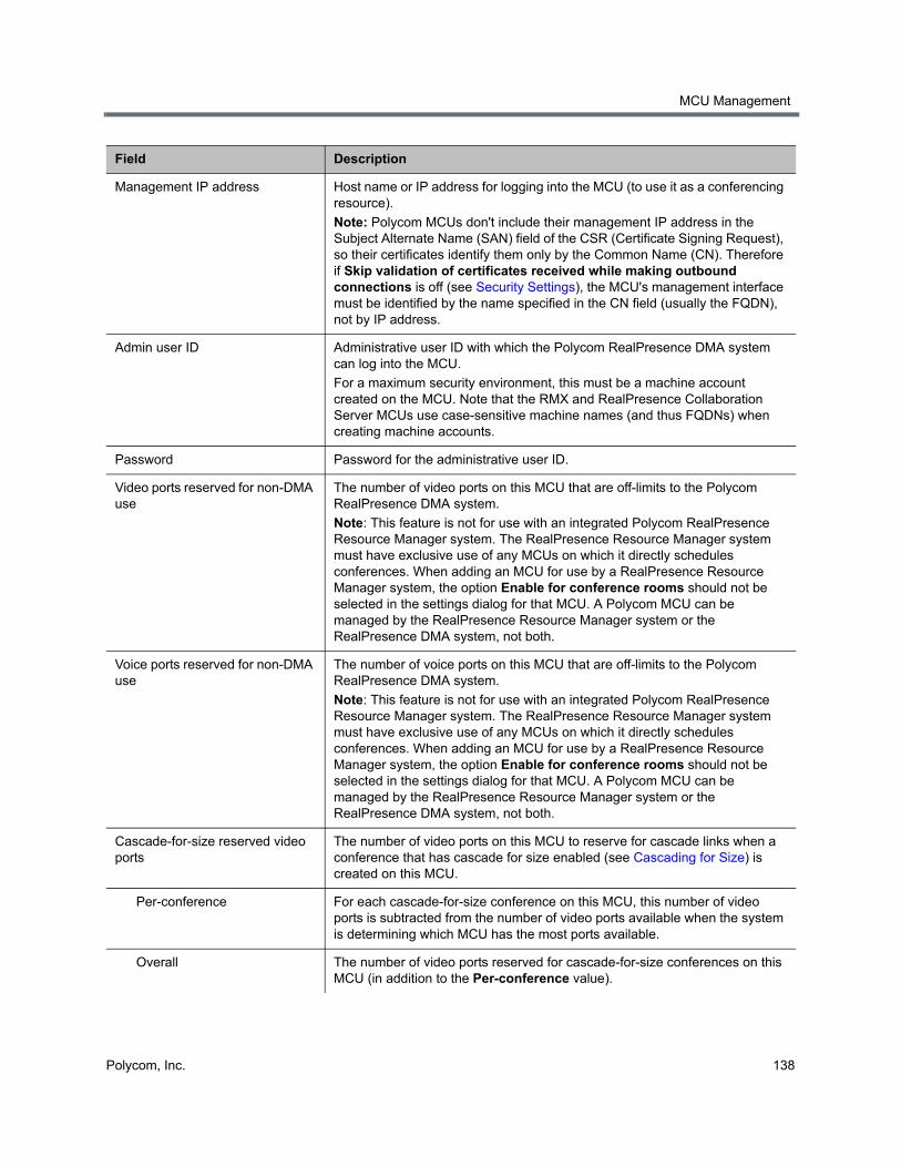
MCU Management
Polycom, Inc. 138
Management IP address Host name or IP address for logging into the MCU (to use it as a conferencing resource).
Note: Polycom MCUs don't include their management IP address in the Subject Alternate Name (SAN) field of the CSR (Certificate Signing Request), so their certificates identify them only by the Common Name (CN). Therefore if Skip validation of certificates received while making outbound connections is off (see Security Settings), the MCU's management interface must be identified by the name specified in the CN field (usually the FQDN), not by IP address.
Admin user ID Administrative user ID with which the Polycom RealPresence DMA system can log into the MCU.
For a maximum security environment, this must be a machine account created on the MCU. Note that the RMX and RealPresence Collaboration Server MCUs use case-sensitive machine names (and thus FQDNs) when creating machine accounts.
Password Password for the administrative user ID.
Video ports reserved for non-DMA use
The number of video ports on this MCU that are off-limits to the Polycom RealPresence DMA system.
Note: This feature is not for use with an integrated Polycom RealPresence Resource Manager system. The RealPresence Resource Manager system must have exclusive use of any MCUs on which it directly schedules conferences. When adding an MCU for use by a RealPresence Resource Manager system, the option Enable for conference rooms should not be selected in the settings dialog for that MCU. A Polycom MCU can be managed by the RealPresence Resource Manager system or the RealPresence DMA system, not both.
Voice ports reserved for non-DMA use
The number of voice ports on this MCU that are off-limits to the Polycom RealPresence DMA system.
Note: This feature is not for use with an integrated Polycom RealPresence Resource Manager system. The RealPresence Resource Manager system must have exclusive use of any MCUs on which it directly schedules conferences. When adding an MCU for use by a RealPresence Resource Manager system, the option Enable for conference rooms should not be selected in the settings dialog for that MCU. A Polycom MCU can be managed by the RealPresence Resource Manager system or the RealPresence DMA system, not both.
Cascade-for-size reserved video ports
The number of video ports on this MCU to reserve for cascade links when a conference that has cascade for size enabled (see Cascading for Size) is created on this MCU.
Per-conference For each cascade-for-size conference on this MCU, this number of video ports is subtracted from the number of video ports available when the system is determining which MCU has the most ports available.
Overall The number of video ports reserved for cascade-for-size conferences on this MCU (in addition to the Per-conference value).
Field Description
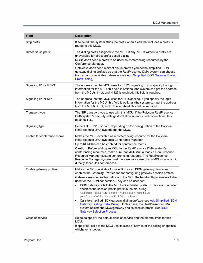
MCU Management
Polycom, Inc. 139
Strip prefix If selected, the system strips the prefix when a call that includes a prefix is routed to this MCU.
Direct dial-in prefix The dialing prefix assigned to the MCU, if any. MCUs without a prefix are unavailable for direct prefix-based dialing.
MCUs don’t need a prefix to be used as conferencing resources by the Conference Manager.
Gateways don’t need a direct dial-in prefix if you define simplified ISDN gateway dialing prefixes so that the RealPresence DMA system can choose from a pool of available gateways (see Add Simplified ISDN Gateway Dialing Prefix Dialog).
Signaling IP for H.323 The address that the MCU uses for H.323 signaling. If you specify the login information for the MCU, this field is optional (the system can get the address from the MCU). If not, and H.323 is enabled, this field is required.
Signaling IP for SIP The address that the MCU uses for SIP signaling. If you specify the login information for the MCU, this field is optional (the system can get the address from the MCU). If not, and SIP is enabled, this field is required.
Transport type The SIP transport type to use with this MCU. If the Polycom RealPresence DMA system‘s security settings don’t allow unencrypted connections, this must be TLS.
Signaling type Select SIP, H.323, or both, depending on the configuration of the Polycom RealPresence DMA system and the MCU.
Enable for conference rooms Makes the MCU available as a conferencing resource for the Polycom RealPresence DMA system’s Conference Manager.
Up to 64 MCUs can be enabled for conference rooms.
Caution: Before adding an MCU to the RealPresence DMA system’s conferencing resources, make sure that MCU isn’t already a RealPresence Resource Manager system conferencing resource. The RealPresence Resource Manager system must have exclusive use of any MCUs on which it directly schedules conferences.
Enable gateway profiles Makes the MCU available for selection as an ISDN gateway device and enables the Gateway Profiles tab for configuring gateway session profiles.
Gateway session profiles indicate to the MCU the bandwidth parameters to be used for the ISDN connection. They can be used for:
• ISDN gateway calls to the MCU’s direct dial-in prefix. In this case, the caller specifies the session profile prefix in the dial string: <direct dial-in prefix><session profile prefix><delimiter><E.164 number>
• Calls to simplified ISDN gateway dialing prefixes (see Add Simplified ISDN Gateway Dialing Prefix Dialog). In this case, the RealPresence DMA system selects the MCU/gateway and its session profile. See ISDN Gateway Selection Process.
Class of service Select to specify the default class of service and the bit rate limits for this MCU.
If specified, calls to the MCU use its class of service or the calling endpoint’s, whichever is better.
Field Description
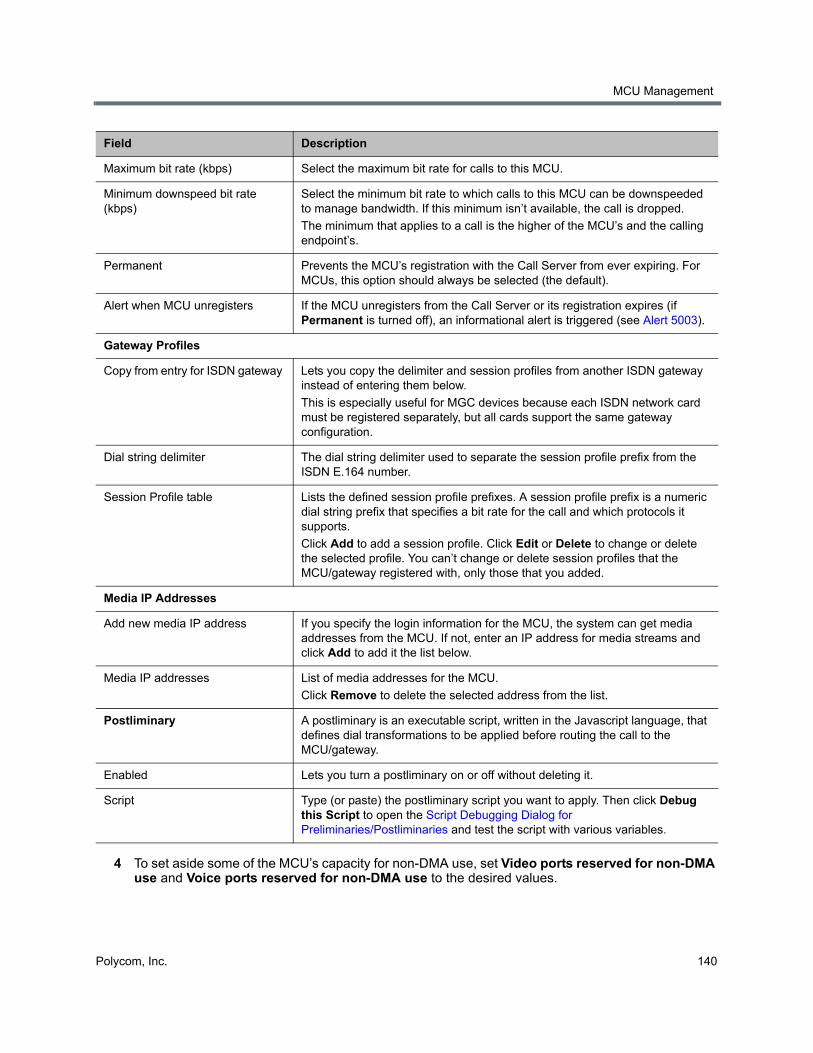
MCU Management
Polycom, Inc. 140
4 To set aside some of the MCU’s capacity for non-DMA use, set Video ports reserved for non-DMA use and Voice ports reserved for non-DMA use to the desired values.
Maximum bit rate (kbps) Select the maximum bit rate for calls to this MCU.
Minimum downspeed bit rate (kbps)
Select the minimum bit rate to which calls to this MCU can be downspeeded to manage bandwidth. If this minimum isn’t available, the call is dropped.
The minimum that applies to a call is the higher of the MCU’s and the calling endpoint’s.
Permanent Prevents the MCU’s registration with the Call Server from ever expiring. For MCUs, this option should always be selected (the default).
Alert when MCU unregisters If the MCU unregisters from the Call Server or its registration expires (if Permanent is turned off), an informational alert is triggered (see Alert 5003).
Gateway Profiles
Copy from entry for ISDN gateway Lets you copy the delimiter and session profiles from another ISDN gateway instead of entering them below.
This is especially useful for MGC devices because each ISDN network card must be registered separately, but all cards support the same gateway configuration.
Dial string delimiter The dial string delimiter used to separate the session profile prefix from the ISDN E.164 number.
Session Profile table Lists the defined session profile prefixes. A session profile prefix is a numeric dial string prefix that specifies a bit rate for the call and which protocols it supports.
Click Add to add a session profile. Click Edit or Delete to change or delete the selected profile. You can’t change or delete session profiles that the MCU/gateway registered with, only those that you added.
Media IP Addresses
Add new media IP address If you specify the login information for the MCU, the system can get media addresses from the MCU. If not, enter an IP address for media streams and click Add to add it the list below.
Media IP addresses List of media addresses for the MCU.
Click Remove to delete the selected address from the list.
Postliminary A postliminary is an executable script, written in the Javascript language, that defines dial transformations to be applied before routing the call to the MCU/gateway.
Enabled Lets you turn a postliminary on or off without deleting it.
Script Type (or paste) the postliminary script you want to apply. Then click Debug this Script to open the Script Debugging Dialog for Preliminaries/Postliminaries and test the script with various variables.
Field Description
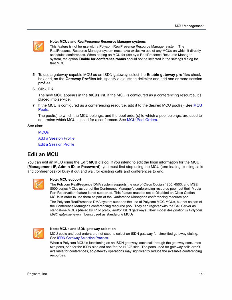
MCU Management
Polycom, Inc. 141
5 To use a gateway-capable MCU as an ISDN gateway, select the Enable gateway profiles check box and, on the Gateway Profiles tab, specify a dial string delimiter and add one or more session profiles.
6 Click OK.
The new MCU appears in the MCUs list. If the MCU is configured as a conferencing resource, it’s placed into service.
7 If the MCU is configured as a conferencing resource, add it to the desired MCU pool(s). See MCU Pools.
The pool(s) to which the MCU belongs, and the pool order(s) to which a pool belongs, are used to determine which MCU is used for a conference. See MCU Pool Orders.
See also:
MCUs
Add a Session Profile
Edit a Session Profile
Edit an MCUYou can edit an MCU using the Edit MCU dialog. If you intend to edit the login information for the MCU (Management IP, Admin ID, or Password), you must first stop using the MCU (terminating existing calls and conferences) or busy it out and wait for existing calls and conferences to end.
Note: MCUs and RealPresence Resource Manager systems
This feature is not for use with a Polycom RealPresence Resource Manager system. The RealPresence Resource Manager system must have exclusive use of any MCUs on which it directly schedules conferences. When adding an MCU for use by a RealPresence Resource Manager system, the option Enable for conference rooms should not be selected in the settings dialog for that MCU.
Note: MCU support
The Polycom RealPresence DMA system supports the use of Cisco Codian 4200, 4500, and MSE 8000 series MCUs as part of the Conference Manager’s conferencing resource pool, but their Media Port Reservation feature is not supported. This feature must be set to Disabled on Cisco Codian MCUs in order to use them as part of the Conference Manager’s conferencing resource pool.
The Polycom RealPresence DMA system supports the use of Polycom MGC MCUs, but not as part of the Conference Manager’s conferencing resource pool. They can register with the Call Server as standalone MCUs (dialed by IP or prefix) and/or ISDN gateways. Their model designation is Polycom MGC gateway, even if being used as standalone MCUs.
Note: MCUs and ISDN gateway selection
MCU pools and pool orders are not used to select an ISDN gateway for simplified gateway dialing. See ISDN Gateway Selection Process.
When a Polycom MCU is functioning as an ISDN gateway, each call through the gateway consumes two ports, one for the ISDN side and one for the H.323 side. The ports used for gateway calls aren’t available for conferences, so gateway operations may significantly reduce the available conferencing resources.
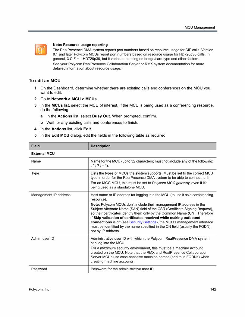
MCU Management
Polycom, Inc. 142
To edit an MCU
1 On the Dashboard, determine whether there are existing calls and conferences on the MCU you want to edit.
2 Go to Network > MCU > MCUs.
3 In the MCUs list, select the MCU of interest. If the MCU is being used as a conferencing resource, do the following:
a In the Actions list, select Busy Out. When prompted, confirm.
b Wait for any existing calls and conferences to finish.
4 In the Actions list, click Edit.
5 In the Edit MCU dialog, edit the fields in the following table as required.
Note: Resource usage reporting
The RealPresence DMA system reports port numbers based on resource usage for CIF calls. Version 8.1 and later Polycom MCUs report port numbers based on resource usage for HD720p30 calls. In general, 3 CIF = 1 HD720p30, but it varies depending on bridge/card type and other factors.
See your Polycom RealPresence Collaboration Server or RMX system documentation for more detailed information about resource usage.
Field Description
External MCU
Name Name for the MCU (up to 32 characters; must not include any of the following: , " ; ? : = *).
Type Lists the types of MCUs the system supports. Must be set to the correct MCU type in order for the RealPresence DMA system to be able to connect to it.
For an MGC MCU, this must be set to Polycom MGC gateway, even if it’s being used as a standalone MCU.
Management IP address Host name or IP address for logging into the MCU (to use it as a conferencing resource).
Note: Polycom MCUs don't include their management IP address in the Subject Alternate Name (SAN) field of the CSR (Certificate Signing Request), so their certificates identify them only by the Common Name (CN). Therefore if Skip validation of certificates received while making outbound connections is off (see Security Settings), the MCU's management interface must be identified by the name specified in the CN field (usually the FQDN), not by IP address.
Admin user ID Administrative user ID with which the Polycom RealPresence DMA system can log into the MCU.
For a maximum security environment, this must be a machine account created on the MCU. Note that the RMX and RealPresence Collaboration Server MCUs use case-sensitive machine names (and thus FQDNs) when creating machine accounts.
Password Password for the administrative user ID.
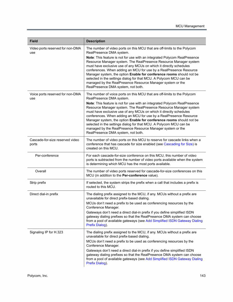
MCU Management
Polycom, Inc. 143
Video ports reserved for non-DMA use
The number of video ports on this MCU that are off-limits to the Polycom RealPresence DMA system.
Note: This feature is not for use with an integrated Polycom RealPresence Resource Manager system. The RealPresence Resource Manager system must have exclusive use of any MCUs on which it directly schedules conferences. When adding an MCU for use by a RealPresence Resource Manager system, the option Enable for conference rooms should not be selected in the settings dialog for that MCU. A Polycom MCU can be managed by the RealPresence Resource Manager system or the RealPresence DMA system, not both.
Voice ports reserved for non-DMA use
The number of voice ports on this MCU that are off-limits to the Polycom RealPresence DMA system.
Note: This feature is not for use with an integrated Polycom RealPresence Resource Manager system. The RealPresence Resource Manager system must have exclusive use of any MCUs on which it directly schedules conferences. When adding an MCU for use by a RealPresence Resource Manager system, the option Enable for conference rooms should not be selected in the settings dialog for that MCU. A Polycom MCU can be managed by the RealPresence Resource Manager system or the RealPresence DMA system, not both.
Cascade-for-size reserved video ports
The number of video ports on this MCU to reserve for cascade links when a conference that has cascade for size enabled (see Cascading for Size) is created on this MCU.
Per-conference For each cascade-for-size conference on this MCU, this number of video ports is subtracted from the number of video ports available when the system is determining which MCU has the most ports available.
Overall The number of video ports reserved for cascade-for-size conferences on this MCU (in addition to the Per-conference value).
Strip prefix If selected, the system strips the prefix when a call that includes a prefix is routed to this MCU.
Direct dial-in prefix The dialing prefix assigned to the MCU, if any. MCUs without a prefix are unavailable for direct prefix-based dialing.
MCUs don’t need a prefix to be used as conferencing resources by the Conference Manager.
Gateways don’t need a direct dial-in prefix if you define simplified ISDN gateway dialing prefixes so that the RealPresence DMA system can choose from a pool of available gateways (see Add Simplified ISDN Gateway Dialing Prefix Dialog).
Signaling IP for H.323 The dialing prefix assigned to the MCU, if any. MCUs without a prefix are unavailable for direct prefix-based dialing.
MCUs don’t need a prefix to be used as conferencing resources by the Conference Manager.
Gateways don’t need a direct dial-in prefix if you define simplified ISDN gateway dialing prefixes so that the RealPresence DMA system can choose from a pool of available gateways (see Add Simplified ISDN Gateway Dialing Prefix Dialog).
Field Description
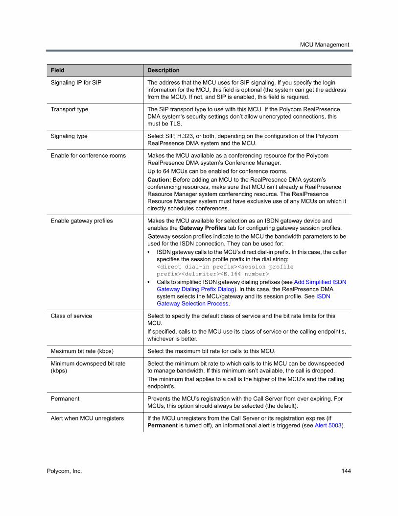
MCU Management
Polycom, Inc. 144
Signaling IP for SIP The address that the MCU uses for SIP signaling. If you specify the login information for the MCU, this field is optional (the system can get the address from the MCU). If not, and SIP is enabled, this field is required.
Transport type The SIP transport type to use with this MCU. If the Polycom RealPresence DMA system‘s security settings don’t allow unencrypted connections, this must be TLS.
Signaling type Select SIP, H.323, or both, depending on the configuration of the Polycom RealPresence DMA system and the MCU.
Enable for conference rooms Makes the MCU available as a conferencing resource for the Polycom RealPresence DMA system’s Conference Manager.
Up to 64 MCUs can be enabled for conference rooms.
Caution: Before adding an MCU to the RealPresence DMA system’s conferencing resources, make sure that MCU isn’t already a RealPresence Resource Manager system conferencing resource. The RealPresence Resource Manager system must have exclusive use of any MCUs on which it directly schedules conferences.
Enable gateway profiles Makes the MCU available for selection as an ISDN gateway device and enables the Gateway Profiles tab for configuring gateway session profiles.
Gateway session profiles indicate to the MCU the bandwidth parameters to be used for the ISDN connection. They can be used for:
• ISDN gateway calls to the MCU’s direct dial-in prefix. In this case, the caller specifies the session profile prefix in the dial string: <direct dial-in prefix><session profile prefix><delimiter><E.164 number>
• Calls to simplified ISDN gateway dialing prefixes (see Add Simplified ISDN Gateway Dialing Prefix Dialog). In this case, the RealPresence DMA system selects the MCU/gateway and its session profile. See ISDN Gateway Selection Process.
Class of service Select to specify the default class of service and the bit rate limits for this MCU.
If specified, calls to the MCU use its class of service or the calling endpoint’s, whichever is better.
Maximum bit rate (kbps) Select the maximum bit rate for calls to this MCU.
Minimum downspeed bit rate (kbps)
Select the minimum bit rate to which calls to this MCU can be downspeeded to manage bandwidth. If this minimum isn’t available, the call is dropped.
The minimum that applies to a call is the higher of the MCU’s and the calling endpoint’s.
Permanent Prevents the MCU’s registration with the Call Server from ever expiring. For MCUs, this option should always be selected (the default).
Alert when MCU unregisters If the MCU unregisters from the Call Server or its registration expires (if Permanent is turned off), an informational alert is triggered (see Alert 5003).
Field Description
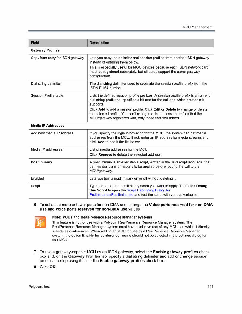
MCU Management
Polycom, Inc. 145
6 To set aside more or fewer ports for non-DMA use, change the Video ports reserved for non-DMA use and Voice ports reserved for non-DMA use values.
7 To use a gateway-capable MCU as an ISDN gateway, select the Enable gateway profiles check box and, on the Gateway Profiles tab, specify a dial string delimiter and add or change session profiles. To stop using it, clear the Enable gateway profiles check box.
8 Click OK.
Gateway Profiles
Copy from entry for ISDN gateway Lets you copy the delimiter and session profiles from another ISDN gateway instead of entering them below.
This is especially useful for MGC devices because each ISDN network card must be registered separately, but all cards support the same gateway configuration.
Dial string delimiter The dial string delimiter used to separate the session profile prefix from the ISDN E.164 number.
Session Profile table Lists the defined session profile prefixes. A session profile prefix is a numeric dial string prefix that specifies a bit rate for the call and which protocols it supports.
Click Add to add a session profile. Click Edit or Delete to change or delete the selected profile. You can’t change or delete session profiles that the MCU/gateway registered with, only those that you added.
Media IP Addresses
Add new media IP address If you specify the login information for the MCU, the system can get media addresses from the MCU. If not, enter an IP address for media streams and click Add to add it the list below.
Media IP addresses List of media addresses for the MCU.
Click Remove to delete the selected address.
Postliminary A postliminary is an executable script, written in the Javascript language, that defines dial transformations to be applied before routing the call to the MCU/gateway.
Enabled Lets you turn a postliminary on or off without deleting it.
Script Type (or paste) the postliminary script you want to apply. Then click Debug this Script to open the Script Debugging Dialog for Preliminaries/Postliminaries and test the script with various variables.
Note: MCUs and RealPresence Resource Manager systems
This feature is not for use with a Polycom RealPresence Resource Manager system. The RealPresence Resource Manager system must have exclusive use of any MCUs on which it directly schedules conferences. When adding an MCU for use by a RealPresence Resource Manager system, the option Enable for conference rooms should not be selected in the settings dialog for that MCU.
Field Description
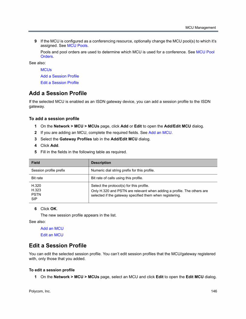
MCU Management
Polycom, Inc. 146
9 If the MCU is configured as a conferencing resource, optionally change the MCU pool(s) to which it’s assigned. See MCU Pools.
Pools and pool orders are used to determine which MCU is used for a conference. See MCU Pool Orders.
See also:
MCUs
Add a Session Profile
Edit a Session Profile
Add a Session ProfileIf the selected MCU is enabled as an ISDN gateway device, you can add a session profile to the ISDN gateway.
To add a session profile
1 On the Network > MCU > MCUs page, click Add or Edit to open the Add/Edit MCU dialog.
2 If you are adding an MCU, complete the required fields. See Add an MCU.
3 Select the Gateway Profiles tab in the Add/Edit MCU dialog.
4 Click Add.
5 Fill in the fields in the following table as required.
6 Click OK.
The new session profile appears in the list.
See also:
Add an MCU
Edit an MCU
Edit a Session ProfileYou can edit the selected session profile. You can’t edit session profiles that the MCU/gateway registered with, only those that you added.
To edit a session profile
1 On the Network > MCU > MCUs page, select an MCU and click Edit to open the Edit MCU dialog.
Field Description
Session profile prefix Numeric dial string prefix for this profile.
Bit rate Bit rate of calls using this profile.
H.320 H.323 PSTN SIP
Select the protocol(s) for this profile.
Only H.320 and PSTN are relevant when adding a profile. The others are selected if the gateway specified them when registering.
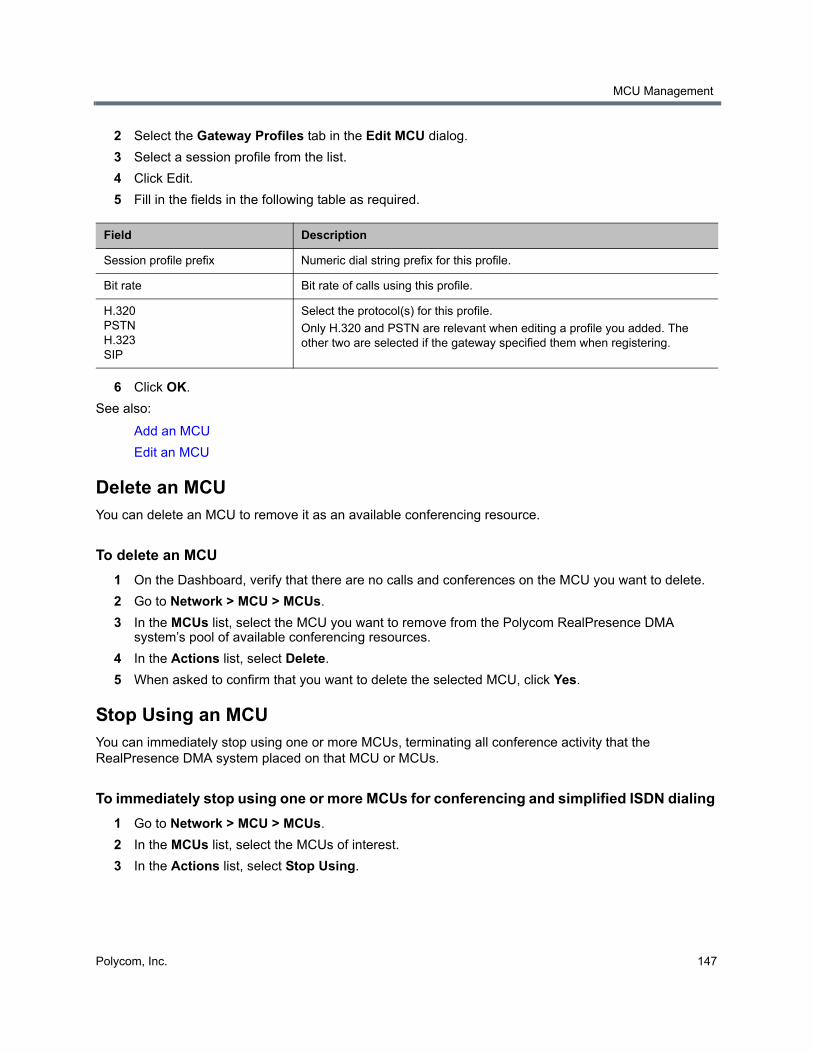
MCU Management
Polycom, Inc. 147
2 Select the Gateway Profiles tab in the Edit MCU dialog.
3 Select a session profile from the list.
4 Click Edit.
5 Fill in the fields in the following table as required.
6 Click OK.
See also:
Add an MCU
Edit an MCU
Delete an MCUYou can delete an MCU to remove it as an available conferencing resource.
To delete an MCU
1 On the Dashboard, verify that there are no calls and conferences on the MCU you want to delete.
2 Go to Network > MCU > MCUs.
3 In the MCUs list, select the MCU you want to remove from the Polycom RealPresence DMA system’s pool of available conferencing resources.
4 In the Actions list, select Delete.
5 When asked to confirm that you want to delete the selected MCU, click Yes.
Stop Using an MCUYou can immediately stop using one or more MCUs, terminating all conference activity that the RealPresence DMA system placed on that MCU or MCUs.
To immediately stop using one or more MCUs for conferencing and simplified ISDN dialing
1 Go to Network > MCU > MCUs.
2 In the MCUs list, select the MCUs of interest.
3 In the Actions list, select Stop Using.
Field Description
Session profile prefix Numeric dial string prefix for this profile.
Bit rate Bit rate of calls using this profile.
H.320 PSTN H.323 SIP
Select the protocol(s) for this profile.
Only H.320 and PSTN are relevant when editing a profile you added. The other two are selected if the gateway specified them when registering.
MCU Management
Polycom, Inc. 148
4 When asked to confirm that you want to stop using the MCUs, click Yes.
The Polycom RealPresence DMA system immediately terminates all H.323 calls and conferences that it placed on those MCUs (for SIP calls only, it migrates the calls to in-service MCUs with available capacity). It also excludes these MCUs from consideration for any future conferences and simplified ISDN dialing calls.
This has no effect on the MCUs themselves, which continue to accept any calls from other sources.
Busy Out an MCUYou can busy out an MCU to allow current conferences to continue, but disallow further conferences from starting.
To stop using one or more MCUs, but allow existing calls and conferences to continue
1 Go to Network > MCU > MCUs.
2 In the MCUs list, select the MCUs of interest.
3 In the Actions list, select Busy Out.
4 When asked to confirm that you want to busy out the MCUs, click Yes.
The Polycom RealPresence DMA system stops creating new conferences on those MCUs, but it allows existing conferences to continue and accepts new calls to those conferences. It also excludes these MCUs from consideration for simplified ISDN dialing calls.
This has no effect on the MCUs themselves, which continue to accept any calls from other sources.
Start Using an MCU AgainYou can put an MCU back in service if it has been stopped or busied out.
To start using one or more MCUs for conferencing and simplified ISDN dialing again
1 Go to Network > MCU > MCUs.
2 In the MCUs list, select the out-of-service MCUs of interest.
3 In the Actions list, select Start Using.
ISDN Gateway Selection ProcessWhen the dial string begins with a simplified ISDN gateway dialing prefix, the Polycom RealPresence DMA system chooses an ISDN gateway by applying the following steps:
1 Strip the ISDN gateway dialing prefix from the dial string, leaving the E.164 number.
2 From the in-service (not busied out or out of service) gateways, select the ones that have a profile with a matching or higher bit rate (higher bit rate can only be used for RealPresence Collaboration Server or RMX MCUs). If none, go to 3; otherwise, go to 4.
3 From the remaining gateways, select those with a profile bit rate lower than the requested bit rate. If none, reject the call.
4 From the remaining gateways, select those that match the country code and area code of the dialed number. If none, go to 5; otherwise, go to 6.
5 From the remaining gateways, select those that match the country code of the dialed number, if any.
MCU Management
Polycom, Inc. 149
6 From the remaining gateways, select those with a profile that has the closest bit rate. An exact match is preferred.
7 From the remaining gateways, select those that are in the same site as the calling endpoint, if any.
8 From the remaining gateways, select one using a round-robin method.
9 If the call fails because of no capacity on the selected gateway, select the next gateway left in 8. If none, start again at 2 (omitting the gateway that failed). If none left, reject the call.
10 If a gateway is successfully selected, assemble a dial string to send to the gateway as follows: <direct dial-in prefix><session profile prefix><delimiter><E.164 number>
See also:
MCUs
Add an MCU
Edit an MCU
MCU PoolsThe MCU Pools list shows the MCU pools, or logical groupings of media servers, that are defined in the Polycom RealPresence DMA system. In a superclustered system, this list is the same on all clusters in the supercluster. A pool may group MCUs based on location, capability, or some other factor.
Every conference room (VMR) is associated with an MCU pool order (either by direct assignment, via the user’s enterprise group membership, or from the system default). The pool(s) to which an MCU belongs, and the pool order(s) to which a pool belongs, are used to determine which MCU is used to host a conference. For details of how an MCU is chosen for a conference, see MCU Pool Orders.
You can use various criteria for organizing MCUs into pools, depending on how you want the MCU resources allocated for conferencing. For instance:
Note: MCU pools vs. MCU zones
MCU pools were called MCU zones in earlier versions of the Polycom RealPresence DMA system. The name was changed to avoid confusion with the concept of gatekeeper zones.
Note: MCU pool orders
If you have a Polycom RealPresence Resource Manager system that uses the RealPresence DMA system API to schedule conferences on the RealPresence DMA system’s conferencing resources (MCU pools), you must create MCU pools and pool orders specifically for the use of the RealPresence Resource Manager system. The pool orders should be named in such a way that:
• They appear at the top of the pool order list presented in the RealPresence Resource Manager system.
• Users of that system will understand that they should choose one of those pool orders.
When adding an MCU for use by a RealPresence Resource Manager system, the option Enable for conference rooms should not be selected in the settings dialog for that MCU.
Note: MCUs and ISDN gateway selection
MCU pools and pool orders are not used to select an ISDN gateway for simplified gateway dialing. See ISDN Gateway Selection Process.
MCU Management
Polycom, Inc. 150
● You could put all MCUs in a specific site or domain into a pool. Then, assign a pool order to all users in that site or domain (via group membership) ensuring that their conferences are preferentially routed to MCUs in that pool.
● You could put one or more MCUs into a pool to be used only by executives, and put that pool into a pool order associated only with those executives’ conference rooms.
● You could put MCUs with special capabilities into a pool, and put that pool into a pool order associated only with custom conference rooms requiring those capabilities.
The following table describes the fields in the list on the Network > MCU > MCU Pools page.
The Actions list associated with the MCU Pools list contains the items in the following table.
See also:
Edit an MCU Pool
Add an MCU Pool You can define a new MCU pool in the RealPresence DMA system.
To add an MCU Pool
1 Go to Network > MCU > MCU Pools.
2 In the Actions list, click Add.
3 In the Add MCU Pool dialog, enter the following required information.
Column Description
Name Name of the MCU pool.
Description Description of the pool, such as the geographic location of the MCUs it contains.
MCUs The MCUs that are in the pool.
Command Description
Add Opens the Add MCU Pool dialog, where you can define a new pool.
Edit Opens the Edit MCU Pool dialog for the selected pool, where you can change its name, description, and the MCUs it includes.
Delete Removes the selected MCU pool from the list of pools that are available. A dialog informs you of the effect on pool orders and asks you to confirm.
Field Description
Name Name of the MCU pool.
Description Description of the pool. This should be something meaningful, such as the geographic location of the MCUs that the pool contains.

MCU Management
Polycom, Inc. 151
4 Click OK.
The new MCU pool appears in the MCU Pools list. The MCUs included in the pool are displayed.
See also:
MCU Pools
Edit an MCU Pool You can edit an existing MCU pool at any time.
To edit an MCU Pool
1 Go to Network > MCU > MCU Pools.
2 In the MCU Pools list, select the pool, and in the Actions list, click Edit.
3 In the Edit MCU Pool dialog, edit the following fields as required.
4 Click OK.
The changes you made appear in the MCU Pools list.
See also:
MCU Pools
Delete an MCU PoolIf an MCU pool is no longer needed, you can remove it from the system.
To delete an MCU Pool
1 Go to Network > MCU > MCU Pools.
2 In the MCU Pools list, select the MCU pool you want to remove.
Available MCUs Lists the MCUs available to the Polycom RealPresence DMA system.
Selected MCUs Lists the MCUs included in the pool. The arrow buttons move MCUs from one list to the other.
Field Description
Name Name of the MCU pool.
Description Brief description of the pool. This should be something meaningful, such as the geographic location of the MCUs that the pool contains.
Available MCUs Lists the MCUs available to the Polycom RealPresence DMA system.
Selected MCUs Lists the MCUs included in the pool. The arrow buttons move MCUs from one list to the other.
Field Description
MCU Management
Polycom, Inc. 152
3 In the Actions list, select Delete.
If the pool is included in one or more pool orders, the system warns you and provides information about the consequences of deleting it.
4 When asked to confirm that you want to delete the selected MCU pool, click Yes.
See also:
MCU Pools
Add an MCU Pool
Edit an MCU Pool
MCU Pool OrdersThe MCU Pool Orders list shows the MCU pool orders that are defined in the Polycom RealPresence DMA system. In a superclustered system, this list is the same on all clusters in the supercluster. A pool order contains one or more MCU pools and specifies the order of preference in which the pools are used.
Every conference room (VMR) is associated with an MCU pool order in one of the following ways:
● By direct assignment. See Edit Conference Room Dialog.
● Via the user’s enterprise group membership.
● From the system default.
The pool(s) to which an MCU belongs, and the pool order(s) to which a pool belongs, are used to determine which MCU is used to host a conference. For some examples of how MCUs can be organized into pools for specific purposes, see MCU Pools.
The following table describes the fields in the list on the Network > MCU > MCU Pool Orders page.
Note: MCU pools vs. MCU zones
MCU pools were called MCU zones in earlier versions of the Polycom RealPresence DMA system. The name was changed to avoid confusion with the concept of gatekeeper zones.
Note: MCU pool orders
If you have a Polycom RealPresence Resource Manager system that uses the RealPresence DMA system API to schedule conferences on the RealPresence DMA system’s conferencing resources (MCU pools), you must create MCU pools and pool orders specifically for the use of the RealPresence Resource Manager system. The pool orders should be named in such a way that:
• They appear at the top of the pool order list presented in the RealPresence Resource Manager system.
• Users of that system will understand that they should choose one of those pool orders.
When adding an MCU for use by a RealPresence Resource Manager system, the option Enable for conference rooms should not be selected in the settings dialog for that MCU.
Column Description
Priority Priority ranking of the pool order.
Name Name of the pool order.
MCU Management
Polycom, Inc. 153
The Actions list associated with the MCU Pool Orders list contains the items in the following table.
See also:
Add an MCU Pool Order
Edit an MCU Pool Order
MCU Selection Process
MCU Availability and Reliability Tracking
Enterprise Groups Procedures
Add an MCU Pool OrderYou can add an MCU pool order to specify the order of preference in which existing MCU pools are used by the system.
To add an MCU pool order
1 Go to Network > MCU > MCU Pool Orders.
2 In the Actions list, click Add.
3 In the Add MCU Pool dialog, complete the following fields. All are mandatory.
Description Brief description of the pool order.
MCU Pools The MCU pools that are in the pool order.
Fallback Indicates whether this pool order is set to fall back to any available MCU if there are no available MCUs in its pools.
Command Description
Add Opens the Add MCU Pool Order dialog, where you can define a new pool order.
Edit Opens the Edit MCU Pool Order dialog for the selected pool order, where you can change its name, description, the MCU pools it includes, and their priority order.
Delete Removes the selected MCU pool order from the list of pool orders that are available. A dialog asks you to confirm.
Move Up Increases the priority ranking of the selected pool order.
Move Down Decreases the priority ranking of the selected pool order.
Field Description
Name Name of the MCU pool order.
Description Brief description of the pool order.
Column Description
MCU Management
Polycom, Inc. 154
4 Click OK.
The new MCU pool order appears in the MCU Pool Orders list. The MCU pools included in the pool order are displayed.
See also:
MCU Pool Orders
Edit an MCU Pool OrderOnce you create an MCU pool order, you can change it at any time.
To edit an MCU pool order
1 Go to Network > MCU > MCU Pool Orders.
2 In the MCU Pool Orders list, select the pool order, and in the Actions list, click Edit.
3 In the Edit MCU Pool Order dialog, edit the following fields as required.
4 Click OK.
The changes you made appear in the MCU Pool Orders list.
See also:
MCU Pool Orders
Delete an MCU Pool OrderIf an MCU pool order is no longer needed, you can delete it from the system.
Available MCU pools Lists the MCU pools available to the system.
Selected MCU pools Lists the pools included in the pool order in their priority order. The left/right arrow buttons move pools in and out of the list. The up/down arrow buttons change the priority rankings of the pools.
Fall back to any available MCU Indicates whether this pool order is set to fall back to any available MCU if there are no available MCUs in its pools.
Field Description
Name Name of the MCU pool order.
Description Brief description of the pool order.
Available MCU pools Lists the MCU pools available to the Polycom RealPresence DMA system.
Selected MCU pools Lists the pools included in the pool order in their priority order. The left/right arrow buttons move pools from one list to the other. The up/down arrow buttons change the priority rank of the selected pool.
Fall back to any available MCU Indicates whether this pool order is set to fall back to any available MCU if there are no available MCUs in its pools.
Field Description
MCU Management
Polycom, Inc. 155
To delete an MCU pool order
1 Go to Network > MCU > MCU Pool Orders.
2 In the MCU Pool Orders list, select the pool order, and in the Actions list, select Delete.
3 When asked to confirm that you want to delete the selected MCU, click Yes.
See also:
MCU Pool Orders
MCU Selection Process
The Polycom RealPresence DMA system chooses an MCU for a user’s conference by applying the following rules in order:
1 Select the MCU pool order:
a Use the pool order directly assigned to the user’s conference room.
b If none, use the highest priority pool order associated with any group to which the user belongs.
c If none, use the system default.
2 Select the first MCU pool in the MCU pool order.
3 Select the best MCU in the MCU pool, based on how well their capabilities fulfill the user’s needs in the following respects:
MCU has RealPresence Collaboration Server or RMX profile required by user’s conference template.
MCU has IVR service required by user’s conference template.
MCU has recording capability required by user’s conference template.
If there are multiple MCUs that are equally capable, select the least used, as determined by the following formula:
port_availability = (free_video_ports / total_video_ports) + (0.0001 * free_audio_ports / total_audio_ports)
mixer_availability = (total_video_ports - 2 * active_dma_conferences) / total_video_ports + 0.0001 * (total_audio_ports - 2 * active_dma_conferences) / total_audio_ports
availability = min (port_availability, mixer_availability)
4 If no MCUs in the selected MCU pool have capacity, select the next MCU pool in the pool order and return to step 3.
5 If no MCUs are available in any of the MCU pools in the pool order:
If fallback is enabled, select the best MCU available to the Polycom RealPresence DMA system, based on the system’s capability algorithm.
If fallback is not enabled, reject the call.
Note: MCUs and ISDN gateway selection
MCU pools and pool orders are not used to select an ISDN gateway for simplified gateway dialing. See ISDN Gateway Selection Process.
The process below can be affected by the mechanisms that the system uses for detecting and handling MCU availability and reliability issues. See MCU Availability and Reliability Tracking.
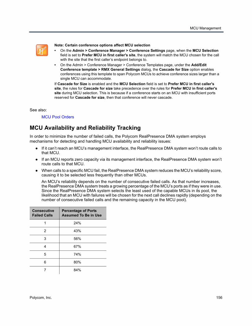
MCU Management
Polycom, Inc. 156
See also:
MCU Pool Orders
MCU Availability and Reliability TrackingIn order to minimize the number of failed calls, the Polycom RealPresence DMA system employs mechanisms for detecting and handling MCU availability and reliability issues:
● If it can’t reach an MCU’s management interface, the RealPresence DMA system won’t route calls to that MCU.
● If an MCU reports zero capacity via its management interface, the RealPresence DMA system won’t route calls to that MCU.
● When calls to a specific MCU fail, the RealPresence DMA system reduces the MCU’s reliability score, causing it to be selected less frequently than other MCUs.
An MCU’s reliability depends on the number of consecutive failed calls. As that number increases, the RealPresence DMA system treats a growing percentage of the MCU’s ports as if they were in use. Since the RealPresence DMA system selects the least used of the capable MCUs in its pool, the likelihood that an MCU with failures will be chosen for the next call declines rapidly (depending on the number of consecutive failed calls and the remaining capacity in the MCU pool).
Note: Certain conference options affect MCU selection
• On the Admin > Conference Manager > Conference Settings page, when the MCU Selection field is set to Prefer MCU in first caller's site, the system will match the MCU chosen for the call with the site that the first caller’s endpoint belongs to.
• On the Admin > Conference Manager > Conference Templates page, under the Add/Edit Conference template > RMX General Settings dialog, the Cascade for Size option enables conferences using this template to span Polycom MCUs to achieve conference sizes larger than a single MCU can accommodate.
If Cascade for Size is enabled and the MCU Selection field is set to Prefer MCU in first caller's site, the rules for Cascade for size take precedence over the rules for Prefer MCU in first caller's site during MCU selection. This is because if a conference starts on an MCU with insufficient ports reserved for Cascade for size, then that conference will never cascade.
Consecutive Failed Calls
Percentage of Ports Assumed To Be in Use
1 24%
2 43%
3 56%
4 67%
5 74%
6 80%
7 84%
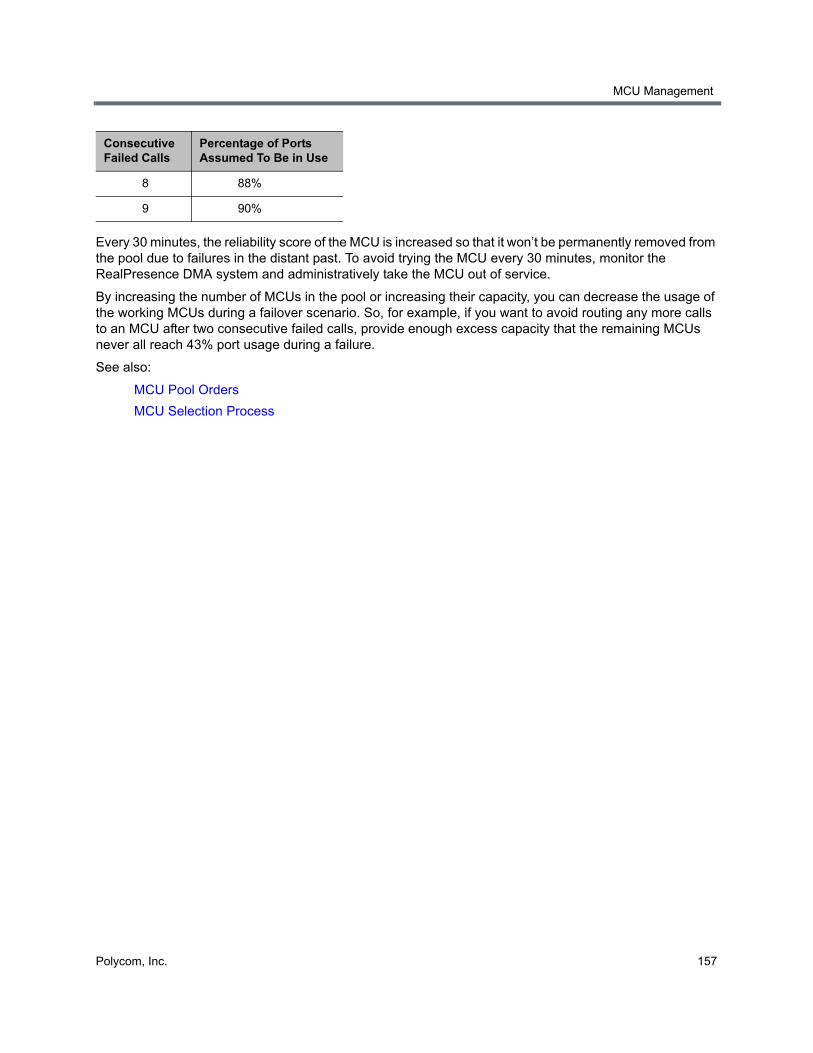
MCU Management
Polycom, Inc. 157
Every 30 minutes, the reliability score of the MCU is increased so that it won’t be permanently removed from the pool due to failures in the distant past. To avoid trying the MCU every 30 minutes, monitor the RealPresence DMA system and administratively take the MCU out of service.
By increasing the number of MCUs in the pool or increasing their capacity, you can decrease the usage of the working MCUs during a failover scenario. So, for example, if you want to avoid routing any more calls to an MCU after two consecutive failed calls, provide enough excess capacity that the remaining MCUs never all reach 43% port usage during a failure.
See also:
MCU Pool Orders
MCU Selection Process
8 88%
9 90%
Consecutive Failed Calls
Percentage of Ports Assumed To Be in Use
Polycom, Inc. 158
Integrations with Other Systems
This section describes the following Polycom® RealPresence® Distributed Media Application™ (DMA®) 7000 system configuration topics related to integrating the system with external systems:
● Microsoft Active Directory® Integration
● Microsoft® Lync® 2013 Integration
● Microsoft Exchange Server Integration
● RealPresence Resource Manager Integration
● Juniper Networks SRC Integration
Microsoft Active Directory® IntegrationWhen you integrate the Polycom RealPresence DMA system with your Microsoft Active Directory®, the enterprise users (Active Directory members) become Conferencing Users in the Polycom RealPresence DMA system. Each enterprise user is (optionally) assigned a conference room, or virtual meeting room (VMR). The conference room IDs are typically generated from the enterprise users’ phone numbers.
Once integrated with Active Directory, the Polycom RealPresence DMA system accesses the directory under the following circumstances:
● Nightly, to update the user and group information in its cache.
● Whenever you force a cache refresh using the Update button.
● To authenticate login passwords.
● To create or delete Polycom conference contacts whenever a publishable VMR is created or deleted (only if the RealPresence DMA system is integrated with Microsoft Lync 2013 and contact creation is enabled).
In a superclustered environment, one cluster is responsible for integrating with Active Directory and updating the cache daily, and the cache is available to all clusters through the replicated shared data store. The other clusters connect to Active Directory only to authenticate user credentials.
Integrations with Other Systems
Polycom, Inc. 159
See also:
Microsoft Active Directory Page
Active Directory Integration Procedure
Understanding Base DN
Add Passcodes for Enterprise Users
About the System’s Directory Queries
Active Directory Integration Report
Conference Room Errors Report
Groups
Enterprise Groups Procedures
Microsoft Active Directory PageThe following table describes the fields on the Microsoft Active Directory page.
Note: Polycom solution and integration support
Polycom Implementation and Maintenance services provide support for Polycom solution components only. Additional services for supported third-party Unified Communications (UC) environments integrated with Polycom solutions are available from Polycom Global Services, and its certified Partners, to help customers successfully design, deploy, optimize, and manage Polycom visual communication within their third-party UC environments.
UC Professional Services for Microsoft Integration is mandatory for Polycom Conferencing for Microsoft Outlook and Microsoft Lync Server or Office Communications Server integrations. Please see http://www.polycom.com/services/professional_services/index.html or contact your local Polycom representative for more information.
If the Active Directory is on Windows Server 2008 R2 and AD integration fails, see http://support.microsoft.com/kb/977180.
Field Description
Enable integration with Microsoft Active Directory® Server
Enables the Active Directory integration fields and the Update button, which initiates a connection to the Microsoft Active Directory.
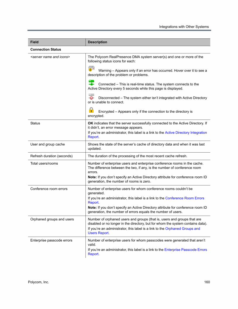
Integrations with Other Systems
Polycom, Inc. 160
Connection Status
<server name and icons> The Polycom RealPresence DMA system server(s) and one or more of the following status icons for each:
Warning – Appears only if an error has occurred. Hover over it to see a description of the problem or problems.
Connected – This is real-time status. The system connects to the Active Directory every 5 seconds while this page is displayed.
Disconnected – The system either isn’t integrated with Active Directory or is unable to connect.
Encrypted – Appears only if the connection to the directory is encrypted.
Status OK indicates that the server successfully connected to the Active Directory. If it didn’t, an error message appears.
If you’re an administrator, this label is a link to the Active Directory Integration Report.
User and group cache Shows the state of the server’s cache of directory data and when it was last updated.
Refresh duration (seconds) The duration of the processing of the most recent cache refresh.
Total users/rooms Number of enterprise users and enterprise conference rooms in the cache. The difference between the two, if any, is the number of conference room errors.
Note: If you don’t specify an Active Directory attribute for conference room ID generation, the number of rooms is zero.
Conference room errors Number of enterprise users for whom conference rooms couldn’t be generated.
If you’re an administrator, this label is a link to the Conference Room Errors Report.
Note: If you don’t specify an Active Directory attribute for conference room ID generation, the number of errors equals the number of users.
Orphaned groups and users Number of orphaned users and groups (that is, users and groups that are disabled or no longer in the directory, but for whom the system contains data).
If you’re an administrator, this label is a link to the Orphaned Groups and Users Report.
Enterprise passcode errors Number of enterprise users for whom passcodes were generated that aren’t valid.
If you’re an administrator, this label is a link to the Enterprise Passcode Errors Report.
Field Description
Integrations with Other Systems
Polycom, Inc. 161
Active Directory Connection
Auto-discover from FQDN If this option is selected, the system uses serverless bind to find the closest global catalog servers. Enter the DNS domain name. We strongly recommend using this option.
If the system can’t determine the site to which it belongs, it tries to connect to any global catalog server.
If that fails, it uses the entered DNS domain name as a host name and continues as if the IP address or host name option were selected.
If this option is checked, the system attempts to connect to the Active Directory as follows:
1 It looks up the LDAP servers for the DNS domain (using DNS SRV: _ldap._tcp.<domain-name>).
2 It LDAP-pings every returned LDAP server until one responds with the system’s client site name.
3 It looks up the global catalog servers for the site (using DNS SRV: _gc._tcp.<site-name>._sites.<domain-name>).
4 It tries to connect to the global catalog servers.
5 If it can’t connect, it tries other global catalog servers from the forest.
6 If it still can’t connect, it uses the DNS domain name (using DNS A: <domain-name>) and connects to it.
Step 6 is the system behavior if this option isn’t checked.
The system’s Network Settings setup must have at least one domain name server specified.
Check the Active Directory Integration Report to see whether serverless bind succeeded and what the site name is.
IP address or host name If this option is selected, the system attempts to connect to the Microsoft Active Directory domain controller specified.
For a single-domain forest, enter the host name or IP address of a domain controller.
For a multi-domain forest, we don’t recommend using this option. If you must, enter the host name or IP address of a specific global catalog server, not the DNS domain name.
The Polycom RealPresence DMA system can only integrate with one forest. A special “Exchange forest” (in which all users are disabled) won’t work because the system doesn’t support conferencing for disabled users.
Domain The Active Directory domain in which the RealPresence DMA system should create and publish Active Directory contacts.
If the system is upgraded from a version prior to 6.2 to version 6.2 or later, the initial value of this field is the Destination network of the SIP Peer configured in Lync pool to create/publish to on the Admin > Conference Manager > Conference Settings page.
Field Description
Integrations with Other Systems
Polycom, Inc. 162
Domain\user name LDAP service account user ID for system access to the Active Directory. Must be set up in the Active Directory, but should not have Windows login privileges.
Note: If you use Active Directory attributes that aren’t replicated across the enterprise via the Global Catalog server mechanism, the system must query each domain for the data. Make sure that this service account can connect to all the LDAP servers in each domain.
The Polycom RealPresence DMA system initially assigns the Administrator user role to this user (see User Roles Overview), so you can use this account to give administrative access to other enterprise user accounts.
Caution: Leaving a user role assigned to this account represents a serious security risk. For best security, remove the Administrator user role and mark this account disabled in the Polycom RealPresence DMA system (not the Active Directory) so that it can’t be used for conferencing or for logging into the Polycom RealPresence DMA system management interface.
Password Login password for service account user ID.
User LDAP filter Specifies which user accounts to include (an underlying, non-editable filter excludes all non-user objects in the directory). The default expression includes all users that don’t have a status of disabled in the directory.
Don’t edit this expression unless you understand LDAP filter syntax. See RFC 2254 for syntax information.
Base DN Can be used to restrict the Polycom RealPresence DMA system to work with a subset of the Active Directory (such as one tree of multiple trees, a subtree, or a domain). Leave the default setting, All Domains, initially. See Understanding Base DN.
Cache Refresh
Number of cache refreshes per day
The number of times per day that the RealPresence DMA system should log in to the directory server(s) and update its cache of user and group data.
Time of day to refresh cache The time at which the RealPresence DMA system should log into the directory server(s) and update its cache of user and group data. If the cache is refreshed more than once per day, this will be one of those times (but not necessarily the first time).
Territory for cache refresh Specifies the territory whose RealPresence DMA system cluster is responsible for updating the user and group data cache.
In a superclustered system, this information is shared across the supercluster. The other clusters access the directory only to authenticate passwords. See Territories for more information.
Field Description
Integrations with Other Systems
Polycom, Inc. 163
Enterprise Conference Room ID Generation
Directory attribute The name of the Active Directory attribute from which the Polycom RealPresence DMA system should derive conference room IDs (virtual meeting room numbers). Generally, organizations use a phone number field for this.
The attribute must be in the Active Directory schema and preferably should be replicated across the enterprise via the Global Catalog server mechanism. But if the attribute isn’t in the Global Catalog, the system queries each domain controller for the data.
Leave this field blank if you don’t want the system to create conference rooms for the enterprise users.
Characters to remove Characters that might need to be stripped from a phone number field’s value to ensure a numeric conference room ID.
The default string includes \t, which represents the tab character. Use \\ to remove backslash characters.
If generating alphanumeric conference room IDs, remove the following:
()&%#@|"':;, Single spaces in the source field are preserved, but multiple consecutive spaces are concatenated to one space.
Maximum characters used Desired length of conference room IDs. The Polycom RealPresence DMA system strips excess characters from the beginning, not the end. If you specify 7, the room IDs will contain the last 7 valid characters from the Active Directory attribute being used.
Enterprise Chairperson and Conference Passcode Generation
Chairperson directory attribute The name of the Active Directory attribute that contains the chairperson passcodes. In choosing an attribute, remember that passcodes must be numeric.
The attribute must be in the Active Directory schema and preferably should be replicated across the enterprise via the Global Catalog server mechanism. But if the attribute isn’t in the Global Catalog, the system queries each domain controller for the data.
Leave this field blank if you don’t want the system to create chairperson passcodes for the enterprise users.
Maximum characters used Desired length of chairperson passcodes. The Polycom RealPresence DMA system strips excess characters from the beginning, not the end. If you specify 7, the passcodes will contain the last 7 numeric characters from the Active Directory attribute being used.
Field Description
Integrations with Other Systems
Polycom, Inc. 164
See also:
Microsoft Active Directory® Integration
Active Directory Cache Refresh FrequencyPeriodically, the system must refresh its cache of users, groups, and conference rooms from Active Directory.
As part of Active Directory integration, you can configure how often the system connects to Active Directory and updates its cache. Be aware that Active Directory cache refreshes can take a variable amount of time to complete, depending on the size of the directory and the amount of data being imported.
Conference directory attribute The name of the Active Directory attribute that contains the conference passcodes. In choosing an attribute, remember that passcodes must be numeric.
The attribute must be in the Active Directory schema and preferably should be replicated across the enterprise via the Global Catalog server mechanism. But if the attribute isn’t in the Global Catalog, the system queries each domain controller for the data.
Leave this field blank if you don’t want the system to create conference passcodes for the enterprise users.
Maximum characters used Desired length of conference passcodes. The Polycom RealPresence DMA system strips excess characters from the beginning, not the end. If you specify 7, the passcodes will contain the last 7 numeric characters from the Active Directory attribute being used.
Lync RealConnectTM
Callback contacts OU The OU the system should use to for managing callback contacts.
The RealPresence DMA system manages a pool of contacts in this dedicated OU and selects an unused contact for each new RealConnectTM conference hosted on an external Lync system. The callback contacts must be configured for Lync availability in Active Directory. Once the conference has ended, the system reclaims the contact for reuse.
For example: If you create a container for callback contact accounts at the root of your Active Directory domain called “CallbackContacts”, specify:
ou=CallbackContactsfor this field. If “CallbackContacts” is under the “Development” container, specify:
ou=CallbackContacts,ou=Developmentfor this field.
For more information on external Lync systems, see External Lync Systems.
For more information on how to configure callback contact accounts in Active Directory, see the Polycom Unified Communications for Microsoft Environments - Solution Deployment Guide.
Note: All callback contacts must be created within a single OU, and you must ensure that there are enough callback contacts in the OU for the cluster to use under heavy conferencing loads. There can be up to 2400 concurrent RealConnectTM conferences hosted on external Lync systems.
Field Description
Integrations with Other Systems
Polycom, Inc. 165
The initial import of data from Active Directory takes roughly three times as long as periodic refreshes.
Active Directory cache refreshes may cause performance issues when the RealPresence DMA system is both under heavy call load and refreshing a large amount of data from the directory (many thousands of users). If a large number of users need to be imported from Active Directory and the RealPresence DMA system is subject to heavy call loads, you should schedule Active Directory cache refreshes during low-load hours.
Cache refresh times are scheduled for the timezone of the RealPresence DMA system where the refresh occurs, but are expressed in the timezone of the browser client. For example: You are located in New York and schedule a cache refresh for 6:00am on a RealPresence DMA system located in London. The cache refresh occurs at 6:00am in the London time zone, but the Active Directory Integration Dashboard pane shows the time of most recent refresh as 2:00am, which was the local time (in New York) when the refresh occurred (in London).
See also:
Microsoft Active Directory® Integration
Active Directory Integration ProcedureBefore performing the procedure below, read Set Up Security and Connect to Microsoft Active Directory®. You should also have a good idea of how many enterprise users you expect the system to retrieve.
To integrate with Active Directory
1 In Windows Server, add the service account (read-only user account) that the RealPresence DMA system will use to read the Active Directory. Configure this account as follows:
User can’t change password.
Password never expires.
User can only access services on the domain controllers and cannot log in anywhere.
If you are integrating the RealPresence DMA system with Lync 2013 and plan to use the automatic conference contact creation feature, the service account you create here should have full permissions to add, change, and delete entries in the OU where the conference contacts are stored, along with full administrative permissions for Lync administration to manipulate these contacts.
Note: Active Directory must trust the RealPresence DMA system certificate
Unless the Allow unencrypted connections to the Active Directory security option is enabled, the RealPresence DMA system offers the same SSL server certificate that it offers to browsers connecting to the system management interface. The Microsoft Active Directory server must be configured to trust the certificate authority.
Integrations with Other Systems
Polycom, Inc. 166
2 In the RealPresence DMA system, replace the default local administrative user with your own user account that has the same user roles. See Users Procedures.
3 Log into the RealPresence DMA system as the local user you created in step 2 and go to Admin > Integrations > Microsoft Active Directory.
4 Check Enable integration with Microsoft® Active Directory Server and complete the information in the Active Directory Connection section.
a Unless you have a single domain environment and no global catalog, select Auto-discover from FQDN and enter the DNS domain name.
b For Domain\user name, enter the domain and user ID of the account you created in step 1.
c For Password, enter the password of the account you created in step 1.
d Leave Base DN set to the default, All Domains. Don’t edit the User LDAP filter expression unless you understand LDAP filter syntax (see RFC 2254) and know what changes to make.
e Specify how many times per day the RealPresence DMA should check the Active Directory for changes.
Consider the information in Active Directory Cache Refresh Frequency when configuring cache refresh settings.
f Specify the time of day the RealPresence DMA system should check the Active Directory for changes.
g Select the territory whose cluster should perform the integration and daily updates.
5 To generate conference room IDs for the enterprise users, complete the Enterprise Conference Room ID Generation section.
Skip this step if you don’t want the system to create conference rooms (virtual meeting rooms) for the enterprise users.
a Specify the Active Directory attribute from which to generate room IDs.
Your users will be happier if room IDs are numeric and not longer than necessary to ensure uniqueness. Phone numbers are the most likely choice, or maybe employee ID numbers.
Note: Active Directory Integration Accounts
If you have a Polycom RealPresence Resource Manager system, be aware that the machine account used for AD integration by the RealPresence Resource Manager system and the service account used for AD integration by the RealPresence DMA system have different requirements. Don’t try to use the same account for both purposes. In particular, the whitelist of machines that the Polycom RealPresence Resource Manager system is allowed to log into should contain only the RealPresence Resource Manager system, while the whitelist of machines the RealPresence DMA system is allowed to log into should contain only the domain controllers.
If you use Active Directory attributes that aren’t replicated across the enterprise via the Global Catalog server mechanism, the system must query each domain for the data. Make sure that the whitelist for this service account is correct and that it can connect to all the LDAP servers in each domain.
Note: Auto-discover vs. IP address
Polycom doesn’t recommend using the IP address or host name option in a multi-domain environment. If you must, enter the host name or IP address of a specific global catalog server, not the DNS domain name.
Integrations with Other Systems
Polycom, Inc. 167
b If necessary, edit the contents of the Characters to remove field.
If you use phone numbers, the default contents of this field should be adequate to ensure a numeric room ID.
c Specify the number of characters to use.
After the system strips out characters to remove, it removes characters in excess of this number from the beginning of the string.
6 If your environment uses external Lync systems, enable the Callback contacts OU field and enter the path of a container that contains callback contact accounts for use with external Lync systems.
For information on how to configure callback contact accounts in Active Directory, see the Polycom Unified Communications for Microsoft Environments - Solution Deployment Guide.
7 Click Update.
After a short time, the system confirms that Active Directory configuration has been updated.
8 Note the time. Click OK.
9 To restrict the RealPresence DMA system to work with a subset of the Active Directory (such as one tree of multiple trees, a subtree, or a domain), repeat steps 4-7, selecting the value you want from those now available in the Base DN list. See Understanding Base DN.
10 Check the Total users/rooms and Conference room errors values. If the numbers are significantly different from what you expected, you’ll need to investigate after you complete the next step (you must be logged in as an enterprise user to investigate further).
11 Set up your enterprise account and secure the service account:
a Log out and log back in using the service account you created in step 1.
You must be logged in with an Active Directory user account to see other enterprise users. The service account user ID specified in step 4b lets you do so initially.
b Go to User > Users, clear the Local users only check box, locate your named enterprise account, and give it Administrator privileges. See User Roles Overview and Users Procedures.
c Log out and log back in using your named enterprise account.
d Secure the service account by removing all user roles and marking it disabled in the RealPresence DMA system (not in the Active Directory). See Edit User Dialog.
12 If, in step 10, the Total users/rooms values were significantly different from what you expected, try to determine the reason and fix it:
a Go to User > Users and perform some searches to determine which enterprise users are available and which aren’t.
Note: Save passcode generation for later
Leave the Enterprise Chairperson and Conference Passcode Generation section alone for now. Once the system is integrated successfully, if you want to add passcode support, see Add Passcodes for Enterprise Users.
Caution: Disable the service account
Leaving user roles assigned to the service account represents a serious security risk. For best security, remove all user roles and mark this account disabled in the Polycom RealPresence DMA system (not the Active Directory) so that this account can’t be used for conferencing or for logging into the Polycom RealPresence DMA system management interface.
Integrations with Other Systems
Polycom, Inc. 168
b If there are many missing or incorrect users, consider whether changes to the LDAP filter can correct the problem or if there is an issue with the directory integration configuration chosen.
13 If, in step 10, there were many conference room errors, try to determine the reason and fix it:
a Go to Reports > Conference Room Errors and verify that the time on the report is after the time when you last completed step 8.
b Review the list of duplicate and invalid conference room IDs. Consider whether using a different Active Directory attribute, increasing the conference room ID length, or editing the characters to remove will resolve the majority of problems.
If there are only a few problems, they can generally be resolved by correcting invalid Active Directory entries.
14 If necessary, repeat steps 4-10 and steps 12 and/or 13, modifying the integration parameters as needed, until you get a satisfactory result.
See also:
Microsoft Active Directory® Integration
Add Passcodes for Enterprise Users
Active Directory Integration Report
Conference Room Errors Report
Understanding Base DNThe Base DN field is where you can specify the distinguished name (DN) of a subset of the Active Directory hierarchy (a domain, subset of domains, or organizational unit) to which you want to restrict the RealPresence DMA system. It acts like a filter.
The following diagram illustrates how choosing different Base DN values affects which parts of a forest are included in the directory integration.
Note: LDAP familiarity
If you’re not familiar with LDAP filter syntax (as defined in RFC 2254) and knowledgeable about enterprise directories in general and your specific implementation in particular, please consult with someone who is.
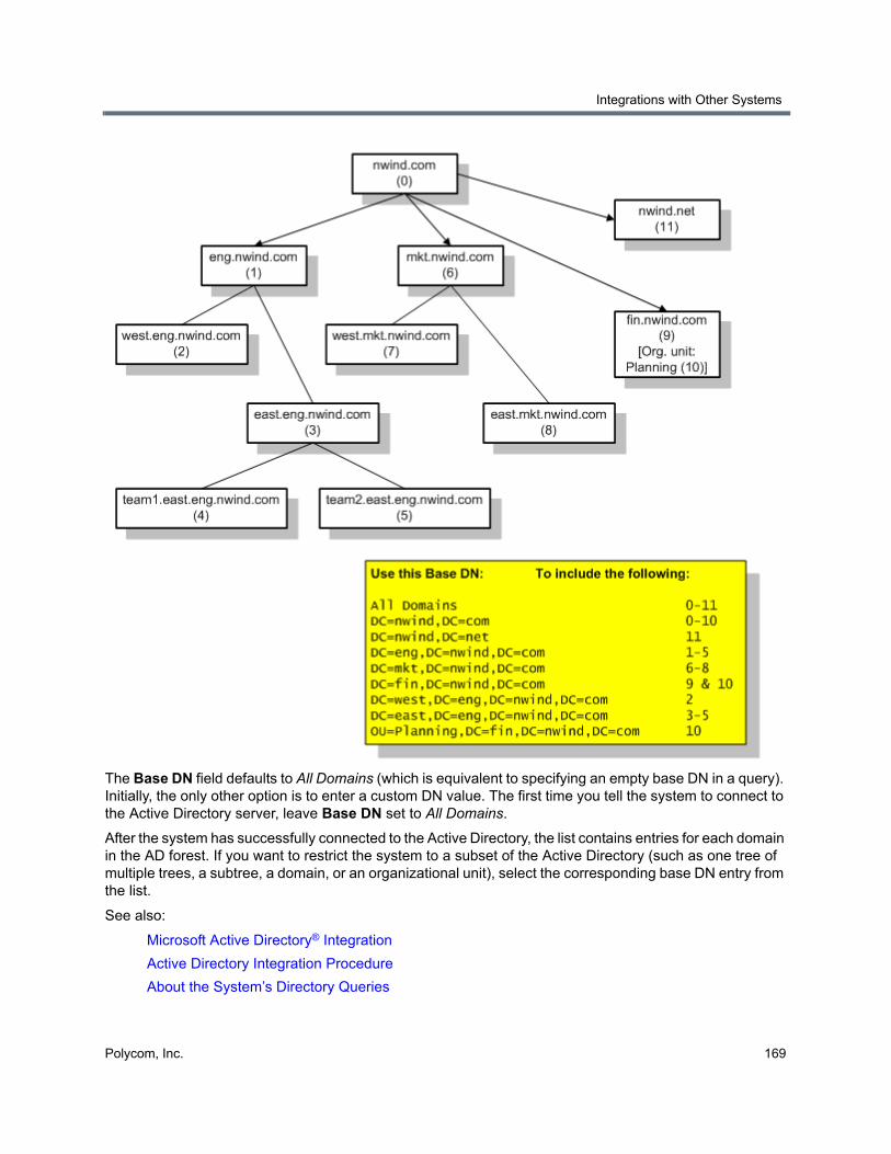
Integrations with Other Systems
Polycom, Inc. 169
The Base DN field defaults to All Domains (which is equivalent to specifying an empty base DN in a query). Initially, the only other option is to enter a custom DN value. The first time you tell the system to connect to the Active Directory server, leave Base DN set to All Domains.
After the system has successfully connected to the Active Directory, the list contains entries for each domain in the AD forest. If you want to restrict the system to a subset of the Active Directory (such as one tree of multiple trees, a subtree, a domain, or an organizational unit), select the corresponding base DN entry from the list.
See also:
Microsoft Active Directory® Integration
Active Directory Integration Procedure
About the System’s Directory Queries
Integrations with Other Systems
Polycom, Inc. 170
Add Passcodes for Enterprise UsersPolycom RMX and RealPresence Collaboration Server MCUs provide two optional security features for conferences, which the Polycom RealPresence DMA system fully supports:
● Conference Passcode — A numeric passcode that callers must enter in order to join the conference.
● Chairperson Passcode — A numeric passcode that callers can enter to identify themselves as conference chairpersons. Chairpersons have additional privileges, such as controlling recording. A conference can be configured to not start until a chairperson joins and to end when the last chairperson leaves (see Add Conference Template Dialog).
If the RealPresence DMA system is integrated with your Active Directory, conference and chairperson passcodes for enterprise users can be maintained in the Active Directory.
You must determine which Active Directory attributes to use for the purpose and provide a process for provisioning users with those passcodes. If a user’s passcode Active Directory attribute (either conference or chairperson) is left empty, the user’s conferences won’t require that passcode.
Passcodes must consist of numeric characters only (the digits 0-9). You can specify the maximum length for each passcode type (up to 16 digits). A user’s conference and chairperson passcodes can’t be the same.
When you generate passcodes for enterprise users, the RealPresence DMA system retrieves the values in the designated Active Directory attributes and removes any non-numeric characters from them. If the resulting numeric passcode is longer than the maximum for that passcode type, it strips the excess characters from the beginning of the string.
To generate chairperson and conference passcodes for enterprise users
1 In the Active Directory, select an unused attribute to be used for each of the passcodes.
In a multi-domain forest, it’s best to choose attributes that are replicated across the enterprise via the Global Catalog server mechanism. But if the attributes you select aren’t available in the Global Catalog, the system can read them directly from each domain.
2 In the Active Directory, either provision users with passcodes or establish a mechanism for letting users create and maintain their own passcodes.
Consult your Active Directory administrator for assistance with this.
3 On the Polycom RealPresence DMA system, go to Admin > Integrations > Microsoft Active Directory.
4 Complete the Enterprise Chairperson and Conference Passcode Generation section.
a Specify the Active Directory attribute from which to generate chairperson passcodes and the number of characters to use.
Note: Cisco Codian MCUs and passcodes
If Cisco Codian MCUs are included in the Polycom RealPresence DMA system’s pool of conferencing resources, don’t assign a chairperson passcode without also assigning a conference passcode. If a conference with only one passcode (either chairperson or conference) lands on a Codian MCU, all callers to the conference must enter that passcode.
Note: Conference passcode selection
You can use an existing attribute that contains numeric data, such as an employee ID. This may not provide much security, but might be sufficient for conference passcodes.
Integrations with Other Systems
Polycom, Inc. 171
b Specify the Active Directory attribute from which to generate conference passcodes and the number of characters to use.
5 Click Update.
After a short time, the system confirms that Active Directory configuration has been updated.
6 Note the time. Click OK.
7 Confirm that passcode generation worked as expected.
a Go to Reports > Enterprise Passcode Errors and verify that the time on the report is after the time when you last completed step 6.
b Review the number of valid, invalid, and unassigned passcodes.
If there are only a few problems, they can generally be resolved by correcting invalid Active Directory entries.
See also:
Microsoft Active Directory® Integration
Microsoft Active Directory Page
Active Directory Integration Procedure
Active Directory Integration Report
About the System’s Directory QueriesThe Polycom RealPresence DMA system uses the following subtree scope LDAP queries. In a standard AD configuration, all these queries use indexes.
● User Search
● Group Search
● Global Group Membership Search
● Attribute Replication Search
● Configurable Attribute Domain Search
● Domain Search
● Service Account Search
The system runs the first three queries every time it creates or updates its cache:
● When you click Update on the Microsoft Active Directory page
● When the system restarts (if integrated with the Active Directory)
● At the scheduled daily cache refresh time
The elements in italics are examples. The actual values of these variables depend on your configuration.
Note: Invalid passcodes
Unless users have already been provisioned with passcodes in your Active Directory or you’re using an existing attribute, most users will probably not have passcodes assigned.
Duplicate and invalid passcodes should be your main concern because they could indicate a problem with the type of data in the selected attributes or with the number of characters you elected to use.
Integrations with Other Systems
Polycom, Inc. 172
User Search
This search queries the global catalog. In a standard AD configuration, all the filter attributes and attributes returned are replicated to the global catalog.
● Base: <empty>
The base variable depends on the Base DN setting on the Microsoft Active Directory page. If it’s set to the default, All Domains, the base variable is empty, as shown. Otherwise, the base variable is the same as Base DN. See Understanding Base DN.
● Filter: (&(objectCategory=person)(UserAccountControl:1.2.840.113556.1.4.803:=512)(sAMAccountName=*)(!(userAccountControl:1.2.840.113556.1.4.803:=2)))
The filter variable depends on the User LDAP filter setting. See Microsoft Active Directory® Integration.
● Index used: idx_objectCategory:32561:N
The search used this index in our testing environment, using a standard AD configuration (no indexes added). Results may be different for a different configuration, especially a different User LDAP filter setting.
● Attributes returned: sAMAccountName, userAccountControl, givenName, sn, [telephoneNumber], [chairpasscode], [confpasscode]
The three attributes returned variables (in square brackets) are returned only if you specify the corresponding Active Directory attributes (for generating conference room IDs, chairperson passcodes, and conference passcodes, respectively) and if the Attribute Replication Search determined that the attributes are replicated to the global catalog.
See Microsoft Active Directory® Integration and Add Passcodes for Enterprise Users.
Group Search
This search queries the global catalog. In a standard AD configuration, all the filter attributes and attributes returned are replicated to the global catalog.
● Base: <empty>
The base variable depends on the Base DN setting on the Microsoft Active Directory page. If it’s set to the default, All Domains, the base variable is empty, as shown. Otherwise, the base variable is the same as Base DN. See Understanding Base DN.
● Filter: (&(objectClass=group)(|(groupType=-2147483640)(groupType=-2147483646)))
● Indexes used: idx_groupType:6675:N;idx_groupType:11:N
The search used these indexes in our testing environment, using a standard AD configuration (no indexes added). Results may be different for a different configuration.
● Attributes returned: cn, description, sAMAccountName, groupType, member
Global Group Membership Search
This search queries LDAP.
● Base: DC=dma,DC=eng,DC=local
The base variable depends on the Base DN setting on the Microsoft Active Directory page. If it’s set to the default, All Domains, the base variable is the domain DN, as shown by the example. Otherwise, the base variable is the same as Base DN. See Understanding Base DN.
Integrations with Other Systems
Polycom, Inc. 173
● Filter: (&(objectClass=group)(groupType=-2147483646))
● Index used: idx_groupType:6664:N
The search used this index in our testing environment, using a standard AD configuration (no indexes added). Results may be different for a different configuration.
● Attributes returned: member
Attribute Replication Search
This search queries LDAP.
The system runs this query when it restarts (if already integrated with the Active Directory) and when you click the Update button on the Microsoft Active Directory page, but only if one or more of the configurable Active Directory attributes (for generating conference room IDs, chairperson passcodes, and conference passcodes) is specified.
The purpose of this query is simply to determine if those Active Directory attributes are replicated to the global catalog. If they are, the User Search retrieves them. If any of them isn’t, the system uses the Configurable Attribute Domain Search to retrieve the data from each domain controller.
● Base: CN=Schema,CN=Configuration,DC=dma,DC=eng,DC=local
The base variable depends on the forest root.
● Filter: (&(lDAPDisplayName=telephoneNumber)(lDAPDisplayName=chairpasscode)(lDAPDisplayName=confpasscode))
The filter variables depend on the configurable Active Directory attributes specified in the Enterprise Conference Room ID Generation and Enterprise Chairperson and Conference Passcode Generation sections (any of these that’s empty is omitted from the filter).
● Indexes used: idx_lDAPDisplayName:3:N;idx_lDAPDisplayName:2:N; idx_lDAPDisplayName:1:N
The search used these indexes in our testing environment, using a standard AD configuration (no indexes added). Results may be different for a different configuration.
● Attributes returned: lDAPDisplayName, isMemberOfPartialAttributeSet
Configurable Attribute Domain Search
This search queries LDAP.
The system runs this query only if the Attribute Replication Search determined that one or more of the configurable Active Directory attributes that it needs to retrieve (for generating conference room IDs, chairperson passcodes, and conference passcodes) isn’t in the global catalog. In that case, it uses this query to retrieve the data from each domain controller.
● Base: DC=dma,DC=eng,DC=local
The base variable depends on the domain name being queried.
● Filter: same as in User Search
● Index used: same as in User Search
● Attributes returned: sAMAccountName, attribute(s) not in global catalog
Domain Search
This search queries LDAP.

Integrations with Other Systems
Polycom, Inc. 174
The system runs this query only when it restarts (if already integrated with the Active Directory) and when you click the Update button on the Microsoft Active Directory page.
● Base: CN=Configuration,DC=dma,DC=eng,DC=local
The base variable depends on the forest root DN (the distinguished name of the Active Directory forest root domain). See Active Directory Integration Report.
● Filter: (&(objectCategory=crossRef)(systemFlags=3))
● Indexes used: idx_objectCategory:11:N
The search used these indexes in our testing environment, using a standard AD configuration (no indexes added). Results may be different for a different configuration.
● Attributes returned: cn, dnsRoot, nCName
Service Account Search
This search queries the global catalog. In a standard AD configuration, all the filter attributes and attributes returned are replicated to the global catalog.
The system runs this query only when you click the Update button on the Microsoft Active Directory page. It validates the service account ID.
● Base: <empty>
The base variable depends on the Base DN setting on the Microsoft Active Directory page. If it’s set to the default, All Domains, the base variable is empty, as shown. Otherwise, the base variable is the same as Base DN. See Understanding Base DN.
● Filter: (&(objectCategory=person)(UserAccountControl:1.2.840.113556.1.4.803:=512)(sAMAccountName=*)(&(!(userAccountControl:1.2.840.113556.1.4.803:=2))(sAMAccountName=<userID>)))
The first filter variable depends on the User LDAP filter setting. See Microsoft Active Directory® Integration. The second variable depends on the value entered in the Service account ID field on the Microsoft Active Directory page. See Microsoft Active Directory® Integration.
● Index used: idx_objectCategory:32561:N
The search used this index in our testing environment, using a standard AD configuration (no indexes added). Results may be different for a different configuration, especially a different User LDAP filter setting.
● Attributes returned: sAMAccountName, userAccountControl, givenName, sn
See also:
Microsoft Active Directory® Integration
Microsoft Active Directory Page
Active Directory Integration Procedure
Understanding Base DN
Microsoft® Lync® 2013 Integration The RealPresence DMA system allows you to integrate with Microsoft® Lync® 2013 Standard Edition and Enterprise Edition environments. When you integrate the RealPresence DMA system into a Lync 2013 environment, the system communicates with the Lync servers and Active Directory to provide contact
Integrations with Other Systems
Polycom, Inc. 175
presence and conference interaction between MCUs managed by the RealPresence DMA system and the Lync AVMCU. Presence allows Lync 2013 clients to view the presence of a RealPresence DMA system VMR, similar to any other contact in the Lync 2013 client contact list.
Callers can also connect to a conference containing a mixture of Lync clients and other endpoints.
The following topics guide you through integration:
● Lync 2010 vs. Lync 2013 Integration
● Scheduled Conferences with Polycom RealConnect™
● Automatic Contact Creation and Configuration
● Active Directory Service Account Permissions
● Lync and non-Lync Endpoint Collaboration
● Considerations and Requirements for Lync 2013 Integration
● Lync 2010 and 2013 Client / Server Feature Support
● Integrate RealPresence DMA and Lync 2013
● Diagnose Presence Problems
Lync 2010 vs. Lync 2013 Integration The RealPresence DMA system can interact with both Lync 2010 and Lync 2013 environments. However, there are several important differences between interacting with a Lync 2010 environment and full integration with a Lync 2013 environment. When Lync 2010 clients call in to the RealPresence DMA system, they connect to a conference as any other SIP endpoint would and are hosted on an MCU managed by the RealPresence DMA system. When the RealPresence DMA system is integrated with Lync 2013, Lync clients that connect to RealPresence DMA system VMRs may be hosted on the Lync AVMCU, and can be part of RealPresence DMA system conferences via a cascade link that the Polycom MCU creates with the AVMCU.
Integration also allows a non-Lync client to connect to a Lync 2013 scheduled conference by dialing the Lync conference ID included in the Microsoft Outlook meeting invitation. The RealPresence DMA system receives the connection attempt, creates a matching VMR automatically, and builds a cascade link between a Polycom MCU and the Lync AVMCU.
If the RealPresence DMA system loses connection with the Lync server, it retries in five minute intervals to reconnect, alerting the administrator of the outage.
Scheduled Conferences with Polycom RealConnect™ The Polycom RealConnect™ scheduled conference scenario is a single workflow for scheduling conferences for Lync and non-Lync endpoints. Once you integrate your system with a Lync 2013 environment, registered endpoints can call through the RealPresence DMA system and join conferences that you schedule with Microsoft Outlook. The Polycom Conferencing for Outlook (PCO) plugin is not needed for Polycom RealConnect™.
Note: VMRs and Polycom conference contacts
Throughout this guide, the term “Polycom conference contact” is used to refer to an Active Directory contact that corresponds with a VMR on the RealPresence DMA system and allows Lync presence status to be published for that VMR. You can configure the RealPresence DMA system to create and delete Polycom conference contacts automatically.
Integrations with Other Systems
Polycom, Inc. 176
Polycom RealConnect™ uses Microsoft Outlook meeting invitations to deliver conference information to participants. When you schedule a conference with Outlook, you can configure the Outlook meeting invitation to include Lync conference IDs in meeting invitations as plain text, in addition to the automatically included “Join Lync Meeting” hypertext link. When they receive the meeting invitation, users of Lync clients can click the link, and users of non-Lync endpoints can dial the plain-text Lync conference ID.
When non-Lync endpoints dial the meeting ID in the meeting invitation, the incoming call is acted on by a dial rule with the action Resolve to Lync conference ID. This dial rule causes the RealPresence DMA system to search any configured and selected SIP peers for a matching Lync conference. If the conference ID isn’t resolved on a Lync server, the system continues attempting to resolve the conference ID using the next dial rule in the list. If the conference ID is resolved on a Lync server, the hosting Lync server gives the RealPresence DMA system information about the conference in question. The RealPresence DMA system dynamically creates a VMR and starts a conference on a Lync-capable MCU, passing the Lync conference information to the MCU. The MCU builds a cascade link between the newly created conference and the conference hosted on the Lync AVMCU. Lync clients and non-Lync endpoints can now interact in the conference.
In a superclustered configuration, endpoints can connect to a RealConnectTM conference from any cluster in the supercluster, but the call will be routed through the supercluster to the cluster that is hosting the RealConnectTM conference.
For information on configuring Microsoft Outlook and Microsoft Lync 2013 to support Polycom RealConnect™, refer to the Polycom Unified Communications for Microsoft Environments - Solution Deployment Guide.
Automatic Contact Creation and Configuration You can configure the RealPresence DMA system to create and manage a corresponding Polycom conference contact in Active Directory whenever users create a new VMR. The RealPresence DMA system communicates with the Lync server to ensure the new contact it is enabled for Lync functionality. This allows the system to publish presence updates to the conference contact; Lync clients display a status of Available, Busy, or Offline for the conference contact in the client’s contact list.
Active Directory Service Account PermissionsIf you integrate the RealPresence DMA system with Lync 2013 and plan to use the automatic conference contact creation feature, note that the required Active Directory service account should have full permissions to add, change, and delete entries in the OU where the conference contacts are stored. The account should also have full administrative permissions for Lync administration to manipulate these contacts.
Note: Polycom RealConnect™requires Polycom MCUs
Polycom RealConnect™ scheduled conferences require that the RealPresence DMA system manage at least one Polycom MCU that supports Lync 2013. Non-Polycom MCUs are not supported.
Note: Lync client contact creation delay
When you manually or automatically create a VMR or group of VMRs, allow up to 10 minutes for the newly created conference contact(s) to appear in the Lync client contact list.
Integrations with Other Systems
Polycom, Inc. 177
Lync and non-Lync Endpoint Collaboration Callers with Lync clients and non-Lync endpoints can join the same conference in several ways. See the Microsoft Lync documentation for more details on specific call flows.
● Users of Lync 2013 clients can select a Polycom conference contact in the contact list and drag it to an ongoing Lync 2013 conversation window, starting a video call.
● Users of Lync 2013 clients can start a Lync conference by selecting the (Show Menu) icon and choosing Meet Now. After starting the conference, users can invite more attendees to the conference or drag a Polycom conference contact into the conversation window to add the participant.
● Users of Lync clients can right-click a Polycom conference contact in the contact list and choose Start a video call.
● Users of Lync clients and other endpoints can use a Microsoft Outlook meeting invitation to connect to a Lync conference. Non-Lync endpoints can dial the included conference ID, and Lync clients can click the “Join Lync Meeting” link included in the invitation.
Considerations and Requirements for Lync 2013 Integration ● For the latest software version requirements and interoperability information, consult the Polycom
Unified Communications in a Microsoft Environment Release Notes.
● The following Virtual Entry Queue (VEQ) call scenarios are not supported:
Calls to a Virtual Entry Queue (VEQ) from a Lync client
A non-Lync endpoint connecting to a VEQ and entering a Lync conference ID when prompted
● The Lync AVMCU doesn’t support incoming calls dialed from a RealPresence DMA system VMR.
● Conference mode configurations of SVC-only and Mixed AVC and SVC are not supported in RealPresence DMA system and Lync 2013 cascaded conferences. Any conference that requires Lync AVMCU connectivity must use conference templates with AVC only as the configured Conference mode.
● You need Lync-capable Polycom MCUs to take advantage of Polycom RealConnectTM functionality.
Non-Polycom MCUs are not supported. If your Polycom MCU is Lync 2013 capable, the icon is displayed next to the MCU name on the Network > MCU > MCUs page. If no MCUs that support Lync 2013 are available, the cascaded RealConnectTM conference won’t start. Refer to your MCU documentation for more information.
Note: Point to point calls between Polycom endpoints and Lync 2013 clients
When you register a Polycom endpoint to a RealPresence DMA system and make a point to point call to a Lync 2013 client, the conference may not have video because the H.261 and H.263 video codecs are not supported by the Lync 2013 client. As a workaround for Polycom HDX and RealPresence Group Series endpoints, register the endpoint to the Lync 2013 server before starting the conference. This workaround requires an RTV option key or Lync Interoperability License.
Note: Point to point calls between Polycom endpoints and Lync 2010 clients
If you add a SIP endpoint on the Network > Endpoints page using the Address of record format <name>@<IP address> and call the endpoint using a Lync 2010 client, the endpoint will not hang up when the call is terminated from the Lync 2010 client. As a workaround, use an Address of record with the format <name>@<SIP domain> when adding the endpoint.
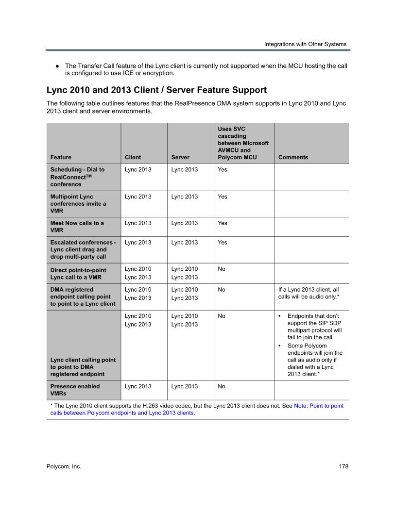
Integrations with Other Systems
Polycom, Inc. 178
● The Transfer Call feature of the Lync client is currently not supported when the MCU hosting the call is configured to use ICE or encryption.
Lync 2010 and 2013 Client / Server Feature Support The following table outlines features that the RealPresence DMA system supports in Lync 2010 and Lync 2013 client and server environments.
Feature Client Server
Uses SVC cascading between Microsoft AVMCU and Polycom MCU Comments
Scheduling - Dial to RealConnectTM conference
Lync 2013 Lync 2013 Yes
Multipoint Lync conferences invite a VMR
Lync 2013 Lync 2013 Yes
Meet Now calls to a VMR
Lync 2013 Lync 2013 Yes
Escalated conferences - Lync client drag and drop multi-party call
Lync 2013 Lync 2013 Yes
Direct point-to-point Lync call to a VMR
Lync 2010
Lync 2013
Lync 2010
Lync 2013
No
DMA registered endpoint calling point to point to a Lync client
Lync 2010
Lync 2013
Lync 2010
Lync 2013
No If a Lync 2013 client, all calls will be audio only.*
Lync client calling point to point to DMA registered endpoint
Lync 2010
Lync 2013
Lync 2010
Lync 2013
No • Endpoints that don’t support the SIP SDP multipart protocol will fail to join the call.
• Some Polycom endpoints will join the call as audio only if dialed with a Lync 2013 client.*
Presence enabled VMRs
Lync 2013 Lync 2013 No
* The Lync 2010 client supports the H.263 video codec, but the Lync 2013 client does not. See Note: Point to point calls between Polycom endpoints and Lync 2013 clients.
Integrations with Other Systems
Polycom, Inc. 179
Integrate RealPresence DMA and Lync 2013 Refer to the Polycom Unified Communications for Microsoft Environments - Solution Deployment Guide for the tasks needed to integrate the RealPresence DMA system with Lync 2013. If you need the RealPresence DMA system to automatically create conference contacts in Active Directory, ensure that your system is integrated with Microsoft Active Directory before proceeding.
Diagnose Presence ProblemsIf after integration your Lync 2013 client does not display presence for RealPresence DMA system VMRs when you enable automatic contact creation and presence publishing, use the following points to begin troubleshooting.
● Check for any active system alerts
The description of any active system alerts can indicate potential issues with integration. See the online help or the Polycom RealPresence DMA 7000 System Operations Guide for a description of the alert text.
● Verify NTP Lync server and RealPresence DMA system use the same NTP source
If the system time differs slightly between the RealPresence DMA system and the Lync server, the Lync server can reject contact creation attempts. See the Admin > Local Cluster > Time Settings page to configure NTP servers.
● Ensure supported MCUs are in service with available ports
See the Network > MCU > MCUs page for an overview of MCU status.
● Ensure that the Publish presence for Polycom conference contacts check box is enabled
This setting, on the Admin > Conference Manager > Conference Settings page, controls system-wide presence publishing for conference contacts.
Microsoft Exchange Server IntegrationOn the Microsoft Exchange Server page, you can integrate the Polycom RealPresence DMA system with your Microsoft Exchange Server, enabling users who install the Polycom Conferencing Add-in for Microsoft Outlook to set up Polycom Conferencing meetings in Outlook.
When you integrate the RealPresence DMA system with an Exchange server, it connects to the Exchange server as the Polycom Conferencing user and subscribes to notifications. The Exchange server notifies the RealPresence DMA system as soon as a meeting invitation (or other mail) arrives in the Polycom Conferencing user inbox. It also sends heartbeat messages to verify that the subscription is working.
If the RealPresence DMA system fails to receive a heartbeat or other notification for 30 seconds, it begins checking its inbox every four minutes for new messages, and also attempts to reestablish the subscription (push connection) each time.
As with other Outlook meeting requests, the meeting organizer invites attendees and specifies where and when to meet. “Where” in this case is a conference room, or virtual meeting room (VMR), on the RealPresence DMA system. The VMR number is generated by the add-in.
The invitees may include conference-room-based Polycom HDX systems as well as users with Polycom HDX personal conferencing endpoints. Polycom HDX systems monitor an Exchange mailbox (either their own or a linked user’s) for Polycom Conferencing meeting invitations.
Integrations with Other Systems
Polycom, Inc. 180
Invitees with a desktop conferencing client (such as Polycom® RealPresence® Desktop) can join the meeting by clicking a link in the Outlook reminder or calendar. Invitees with a Polycom HDX endpoint can join by clicking a link on the HDX system’s reminder.
The add-in also sends Polycom Conferencing meeting invitations to a Polycom Conferencing user mailbox on the Exchange server. The RealPresence DMA system accepts or declines these invitations. A meeting invitation is declined if:
● The VMR number is in use by any other conference room (calendared, enterprise, or custom).
● The user sending the invitation isn’t in the Polycom RealPresence DMA system’s Active Directory cache.
● The invitation contains invalid or incomplete meeting data (the machine-readable metadata block at the bottom of the invitation labeled “POLYCOM VMR ENCODED TOKEN” and preceded with a warning not to edit).
● The meeting’s duration exceeds the system’s Conference Duration setting (see Conference Settings).
● The conference or chairperson passcode is not valid (see Add Passcodes for Enterprise Users).
Polycom Solution and Integration SupportPolycom Implementation and Maintenance services provide support for Polycom solution components only. Additional services for supported third-party Unified Communications (UC) environments integrated with Polycom solutions are available from Polycom Global Services, and its certified Partners, to help customers successfully design, deploy, optimize, and manage Polycom visual communication within their third-party UC environments. UC Professional Services for Microsoft Integration is mandatory for Polycom Conferencing for Microsoft Outlook and Microsoft Office Communications Server integrations. Please see http://www.polycom.com/services/professional_services/index.html or contact your local Polycom representative for more information.
Differences between Calendaring and SchedulingNote that calendaring is not the same as scheduling. Using the Polycom Conferencing Add-in for Microsoft Outlook to set up a meeting appointment doesn’t reserve video resources, and invitations aren’t declined due to lack of resources.
The Polycom RealPresence DMA system supports the use of Cisco Codian 4200, 4500, and MSE 8000 series MCUs as part of its conferencing resource pool. If you use Codian MCUs to host Polycom Conferencing (calendared) meetings, be aware of these limitations:
● Codian MCUs don’t support the Polycom Conferencing Add-in’s recording and streaming options.
● Codian MCUs don’t provide the “gathering phase” that RMX and RealPresence Collaboration Server MCUs provide at the beginning of the conference.
Codian MCUs can’t receive and accept Outlook meeting invitations themselves, and can only be used if a RealPresence DMA system is part of the Polycom Conferencing for Outlook solution.
Note: Exchange Server integration and maximum security mode
Exchange Server integration can’t be enabled in maximum security mode. See The Consequences of Enabling Maximum Security Mode.
Integrations with Other Systems
Polycom, Inc. 181
See also:
Integrations with Other Systems
Exchange Server Integration Procedure
Microsoft Exchange Server PageThe following table describes the fields on the Microsoft Exchange Server page.
See also:
Microsoft Exchange Server Integration
Exchange Server Integration ProcedureUnless the Allow unencrypted calendar notifications from Exchange server security option is enabled (see Security Settings), the RealPresence DMA system offers the same SSL server certificate that it offers to browsers connecting to the system management interface. The Exchange server must be configured to trust the certificate authority in order for the RealPresence DMA system to subscribe to notifications.
If the RealPresence DMA system is configured with a self-signed certificate and the Allow unencrypted calendar notifications from Exchange server security option is disabled, Exchange server integration will fail.
If the RealPresence DMA system is unable to subscribe to notifications, the Exchange Server status (see Dashboard) remains Subscription pending indefinitely and the RealPresence DMA system doesn’t automatically receive calendar notifications. Instead, it must check the Polycom Conferencing mailbox for meeting request messages, which it does every 4 minutes.
Complete the following steps to integrate your system with an Exchange server.
Field Description
Enable integration with Microsoft® Exchange Server
Enables the Exchange server integration fields and the Update button, which initiates a connection to Microsoft Exchange server.
Exchange Server address Fully qualified domain name (FQDN) or IP address of the Exchange server.
Domain\user name The user ID for the Polycom Conferencing infrastructure mailbox on the Exchange server.
Password The password for the Polycom Conferencing user ID.
Territory Select a territory, thereby determining which Polycom RealPresence DMA cluster is responsible for integrating with the Exchange server and monitoring the Polycom Conferencing infrastructure mailbox. See Territories for more information.
Accept Exchange notifications from these additional IP addresses
If you have multiple Exchange servers behind a load balancer, specify the IP address of each individual Exchange server.
Integrations with Other Systems
Polycom, Inc. 182
To integrate the Polycom RealPresence DMA system with your Exchange server
1 Confirm that the RealPresence DMA system has been successfully integrated with your Active Directory (see Integrations with Other Systems) and verify the domain.
Successful Exchange integration requires that the Polycom RealPresence DMA system be integrated with Microsoft Active Directory.
2 Ensure that the DNS server used by the Microsoft Exchange server (usually, the nearest Active Directory domain controller) has an A record for the RealPresence DMA system that resolves the system’s FQDN to its virtual IP address.
3 On the Microsoft Exchange server, create the Polycom Conferencing user that the add-in will automatically invite to Polycom Conferencing meetings.
When creating the user ID for the system, be sure to specify the same domain used to integrate with the Active Directory. Specify the Display Name as you want it to appear in the To field of invitations. We recommend using Polycom Conference (first and last name respectively).
4 Go to Admin > Integrations > Microsoft Exchange Server.
5 Check Enable integration with Microsoft® Exchange Server and specify the address (host name or IP address) of the Exchange server.
6 Specify the login credentials for the system on the Exchange server.
7 Set Territory to the territory of the Polycom RealPresence DMA cluster to be responsible for calendaring.
8 If you have multiple Exchange servers behind a load balancer, under Accept Exchange notifications from these additional IP addresses, add the IP address of each individual Exchange server.
9 Click Update.
A dialog informs you that the configuration has been updated.
10 Click OK.
11 Install the Polycom Conferencing Add-in for Microsoft Outlook on your PC and create the configuration to be distributed to your users (see the online help for the Add-in). Optionally, customize the invitation template(s).
12 Distribute the Polycom Conferencing Add-in for Microsoft Outlook, its configuration file, and customized templates to your users (see the System Administrator Guide for the Polycom® Conferencing Add-in for Microsoft® Outlook®).
See also:
Microsoft Exchange Server Integration
Microsoft Exchange Server Page
Caution: Use a dedicated mailbox for meeting invitations
Create a dedicated Polycom Conferencing mailbox that’s used specifically and exclusively for the purpose of receiving Polycom Conferencing meeting invitations. This is important because the Polycom RealPresence DMA system will delete all messages from the Inbox when it checks this mailbox for meeting invitations.
Integrations with Other Systems
Polycom, Inc. 183
RealPresence Resource Manager IntegrationIntegrating with a RealPresence Resource Manager system provides the RealPresence DMA system with:
● All site topology information configured in the RealPresence Resource Manager system.
The Polycom RealPresence DMA system uses site topology information for a variety of purposes, including cascade for bandwidth conferences, bandwidth management, and Session Border Controller selection. See About Cascading and About the Call Server Capabilities.
● All user-to-device associations configured in the RealPresence Resource Manager system.
The RealPresence DMA system uses user-to-device association to assign classes of service to endpoints based on the user they belong to. See Associate User Dialog.
Integrating with a RealPresence Resource Manager system allows you to configure site topology and user-to-device associations in one place instead of two, ensuring consistency. If you don’t have a RealPresence Resource Manager system (or for some reason don’t want to integrate to it), both kinds of information can be manually configured on the RealPresence DMA system.
While the RealPresence DMA system is integrated with the RealPresence Resource Manager system, site topology and user-to-device association may only be configured on the RealPresence Resource Manager system. If the integration is terminated, the RealPresence DMA system retains the information last obtained from the RealPresence Resource Manager system, but it becomes editable.
The Bit rate to bandwidth conversion factor setting on the Call Server Settings page of the RealPresence DMA system can affect choices for bandwidth restrictions in your site topology. Since the RealPresence Resource Manager system calculates call bandwidth requirements using a conversion factor of 2.5, Polycom recommends using a Bit rate to bandwidth conversion factor value of 2.5 if you integrate with a RealPresence Resource Manager system. Otherwise, you will need to alter the bandwidth restrictions for your site topology to take into account the conversion factor value so that the RealPresence DMA system’s call bandwidth requirement calculations are predictable.
Note: Split Network configuration and resource management system integration
The RealPresence DMA system currently does not support integration with a Polycom RealPresence Resource Manager system when configured for split network interfaces on the Admin > Local Cluster > Network Settings page.
Note: Considerations for RealPresence Resource Manager integration
Integrating a RealPresence Resource Manager system to a RealPresence DMA system enables the RealPresence Resource Manager system to use the RealPresence DMA system’s RealPresence Platform API to set up and monitor scheduled and preset dial-out (anytime) conferences using the RealPresence DMA system’s resources (see RealPresence® Platform API).
When you integrate the Polycom RealPresence Resource Manager system to a RealPresence DMA supercluster with embedded DNS enabled (see Embedded DNS), in its Add DMA dialog, select Support DMA Supercluster.
Note: Add required DNS servers to the system
DNS servers must be able to resolve the RealPresence DMA system’s FQDN to its IP address. See Add Required DNS Records for the Polycom RealPresence DMA System.
In addition, the DNS servers must be able to resolve the Polycom RealPresence Resource Manager system’s FQDN to its IP address. This is necessary even if you specify the Polycom RealPresence Resource Manager system’s IP address when you join it.
Integrations with Other Systems
Polycom, Inc. 184
See also:
Integrations with Other Systems
RealPresence Resource Manager Integration
RealPresence Resource Manager Integration Procedures
RealPresence Resource Manager PageYou can integrate the RealPresence DMA system with a RealPresence Resource Manager system from the Network Device > DMA page of the RealPresence Resource Manager management interface.
When the system is integrated with a RealPresence Resource Manager system, the RealPresence Resource Manager page contains the Leave RealPresence Resource Manager command, which you use to terminate the integration.
The list on this page displays information about the RealPresence Resource Manager system. The following table describes the fields in the list.
Note: Imported site topology information and territories
When it gets site topology from a RealPresence Resource Manager system, the RealPresence DMA system enables for conference rooms the first three territories assigned to a RealPresence DMA cluster.
Note: Delegated authentication
If the Allow delegated authentication to enterprise directory server option on the Polycom RealPresence Resource Manager system is not configured and working properly, the RealPresence DMA system doesn’t receive user-to-device association data for enterprise users and intermittently generates alert 2001.
Note: Other considerations for Resource Management integration
RealPresence Resource Manager integration is not supported in Maximum security mode. See The Consequences of Enabling Maximum Security Mode.
If you want to support cascading for bandwidth, but don’t have a Polycom RealPresence Resource Manager system, you must create site topology information on the Polycom RealPresence DMA system. See Site Topology.
Note: Considerations for RealPresence Resource Manager integration
Integrating a RealPresence Resource Manager system to a RealPresence DMA system enables the RealPresence Resource Manager system to use the RealPresence DMA system’s RealPresence Platform API to set up and monitor scheduled and preset dial-out (anytime) conferences using the RealPresence DMA system’s resources (see RealPresence® Platform API).
When you integrate the Polycom RealPresence Resource Manager system to a RealPresence DMA supercluster with embedded DNS enabled (see Embedded DNS), in its Add DMA dialog, select Support DMA Supercluster.
Integrations with Other Systems
Polycom, Inc. 185
See also:
Integrations with Other Systems
RealPresence Resource Manager Integration
RealPresence Resource Manager Integration Procedures
To terminate the integration with a RealPresence Resource Manager system
1 Go to Admin > Integrations > RealPresence Resource Manager.
2 In the Actions list, select Leave RealPresence Resource Manager.
Field Description
Host name Name of the system.
IP Address IP address of the system.
Model Type of system.
Version Software version of the system.
Status Status of last attempt to contact system (OK or Unreachable).
Time Time of last attempt to contact system.
Note: Maximum security mode and RealPresence Resource Manager integration
RealPresence Resource Manager integration is not supported in Maximum security mode. See The Consequences of Enabling Maximum Security Mode.
Note: Add required DNS servers to the system
DNS servers must be able to resolve the RealPresence DMA system’s FQDN to its IP address. See Add Required DNS Records for the Polycom RealPresence DMA System.
In addition, the DNS servers must be able to resolve the RealPresence Resource Manager system’s FQDN to its IP address.
Note: Delegated authentication
If the Allow delegated authentication to enterprise directory server option on the RealPresence Resource Manager system is not configured and working properly, the RealPresence DMA system doesn’t receive user-to-device association data for enterprise users and intermittently generates alert 2001.
Note: Considerations for RealPresence Resource Manager integration
When you integrate the RealPresence Resource Manager system to a RealPresence DMA supercluster with embedded DNS enabled (see Embedded DNS), in its Add DMA dialog, select Support DMA Supercluster.
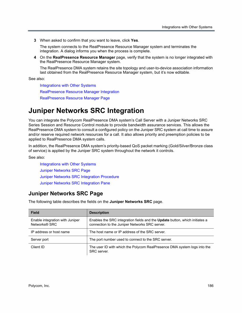
Integrations with Other Systems
Polycom, Inc. 186
3 When asked to confirm that you want to leave, click Yes.
The system connects to the RealPresence Resource Manager system and terminates the integration. A dialog informs you when the process is complete.
4 On the RealPresence Resource Manager page, verify that the system is no longer integrated with the RealPresence Resource Manager system.
The RealPresence DMA system retains the site topology and user-to-device association information last obtained from the RealPresence Resource Manager system, but it’s now editable.
See also:
Integrations with Other Systems
RealPresence Resource Manager Integration
RealPresence Resource Manager Page
Juniper Networks SRC IntegrationYou can integrate the Polycom RealPresence DMA system’s Call Server with a Juniper Networks SRC Series Session and Resource Control module to provide bandwidth assurance services. This allows the RealPresence DMA system to consult a configured policy on the Juniper SRC system at call time to assure and/or reserve required network resources for a call. It also allows priority and preemption policies to be applied to RealPresence DMA system calls.
In addition, the RealPresence DMA system’s priority-based QoS packet marking (Gold/Silver/Bronze class of service) is applied by the Juniper SRC system throughout the network it controls.
See also:
Integrations with Other Systems
Juniper Networks SRC Page
Juniper Networks SRC Integration Procedure
Juniper Networks SRC Integration Pane
Juniper Networks SRC PageThe following table describes the fields on the Juniper Networks SRC page.
Field Description
Enable integration with Juniper Networks® SRC
Enables the SRC integration fields and the Update button, which initiates a connection to the Juniper Networks SRC server.
IP address or host name The host name or IP address of the SRC server.
Server port The port number used to connect to the SRC server.
Client ID The user ID with which the Polycom RealPresence DMA system logs into the SRC server.
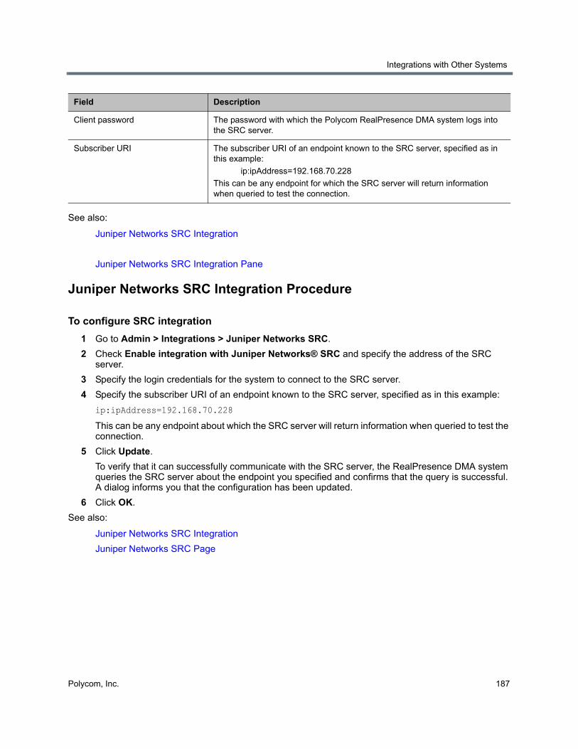
Integrations with Other Systems
Polycom, Inc. 187
See also:
Juniper Networks SRC Integration
Juniper Networks SRC Integration Pane
Juniper Networks SRC Integration Procedure
To configure SRC integration
1 Go to Admin > Integrations > Juniper Networks SRC.
2 Check Enable integration with Juniper Networks® SRC and specify the address of the SRC server.
3 Specify the login credentials for the system to connect to the SRC server.
4 Specify the subscriber URI of an endpoint known to the SRC server, specified as in this example:
ip:ipAddress=192.168.70.228
This can be any endpoint about which the SRC server will return information when queried to test the connection.
5 Click Update.
To verify that it can successfully communicate with the SRC server, the RealPresence DMA system queries the SRC server about the endpoint you specified and confirms that the query is successful. A dialog informs you that the configuration has been updated.
6 Click OK.
See also:
Juniper Networks SRC Integration
Juniper Networks SRC Page
Client password The password with which the Polycom RealPresence DMA system logs into the SRC server.
Subscriber URI The subscriber URI of an endpoint known to the SRC server, specified as in this example:
ip:ipAddress=192.168.70.228
This can be any endpoint for which the SRC server will return information when queried to test the connection.
Field Description
Polycom, Inc. 188
Conference Manager Configuration
This section describes the following Polycom® RealPresence® Distributed Media Application™ (DMA®) 7000 system configuration topics related to the Conference Manager functionality:
● Conference Settings
● Conference Templates
● External Lync Systems
● IVR Prompt Sets
● Shared Number Dialing
Conference SettingsOn the Conference Settings page, you can define the default class of service and bit rate limits, a dialing prefix, and various default conference properties for the Polycom RealPresence DMA system. If the system is integrated with a Microsoft® Lync 2013 environment, you can also configure system-wide default settings related to Presence Publishing for Polycom conference contacts. The following table describes the properties on this page.
Field Description
Default class of service The class of service assigned to a user or endpoint if the class of service isn’t specified at the endpoint, user, or group level.
Note: The class of service of the device applies to point to point calls. VMR calls use the class of service of the conference room.
Default maximum bit rate (kbps) The maximum bit rate for a call if the maximum bit rate for the user or endpoint isn’t specified at the endpoint, user, or group level.
Default minimum downspeed (kbps)
The minimum bit rate to which a call can be reduced (downspeeded) if the minimum downspeed for the user or endpoint isn’t specified at the endpoint, user, or group level.
Dialing prefix Numeric dial string prefix for calling VMRs and VEQs.
If neighboring with a Polycom gatekeeper on which the Simplified Dialing service is enabled and uses a prefix of 9 (the default), don’t use 90-99. The neighbor gatekeeper recognizes the 9 as a known prefix and ignores the second digit.
If a prefix is specified, it’s used for SIP calls as well so that the same number can be dialed from both H.323 and SIP endpoints.
Caution: Changing the dialing prefix terminates any existing H.323 calls. When you click Update, the system prompts you to confirm.
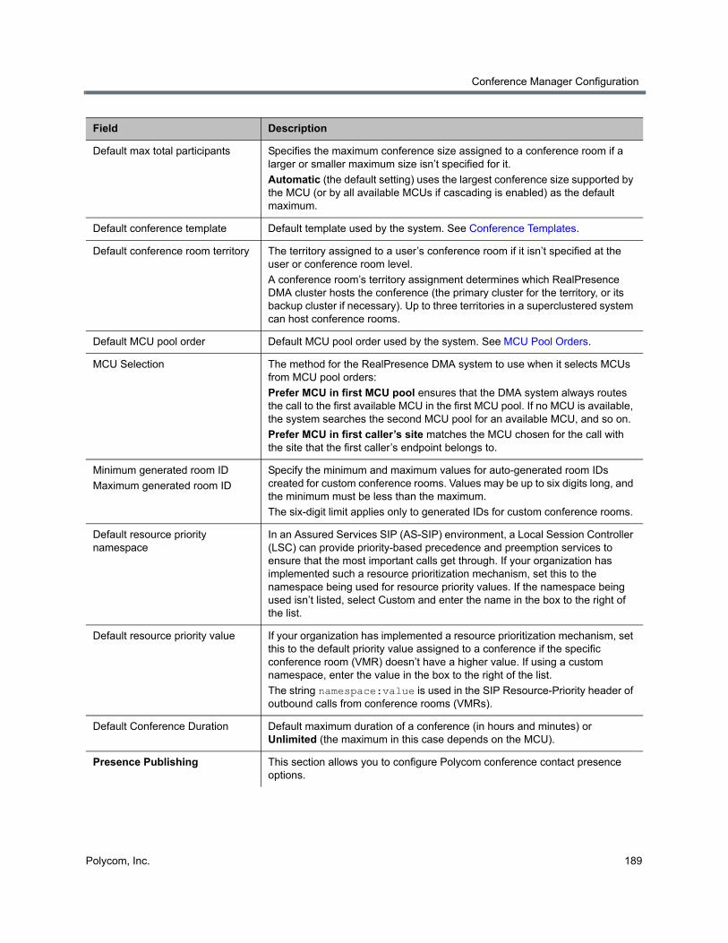
Conference Manager Configuration
Polycom, Inc. 189
Default max total participants Specifies the maximum conference size assigned to a conference room if a larger or smaller maximum size isn’t specified for it.
Automatic (the default setting) uses the largest conference size supported by the MCU (or by all available MCUs if cascading is enabled) as the default maximum.
Default conference template Default template used by the system. See Conference Templates.
Default conference room territory The territory assigned to a user’s conference room if it isn’t specified at the user or conference room level.
A conference room’s territory assignment determines which RealPresence DMA cluster hosts the conference (the primary cluster for the territory, or its backup cluster if necessary). Up to three territories in a superclustered system can host conference rooms.
Default MCU pool order Default MCU pool order used by the system. See MCU Pool Orders.
MCU Selection The method for the RealPresence DMA system to use when it selects MCUs from MCU pool orders:
Prefer MCU in first MCU pool ensures that the DMA system always routes the call to the first available MCU in the first MCU pool. If no MCU is available, the system searches the second MCU pool for an available MCU, and so on.
Prefer MCU in first caller’s site matches the MCU chosen for the call with the site that the first caller’s endpoint belongs to.
Minimum generated room ID
Maximum generated room ID
Specify the minimum and maximum values for auto-generated room IDs created for custom conference rooms. Values may be up to six digits long, and the minimum must be less than the maximum.
The six-digit limit applies only to generated IDs for custom conference rooms.
Default resource priority namespace
In an Assured Services SIP (AS-SIP) environment, a Local Session Controller (LSC) can provide priority-based precedence and preemption services to ensure that the most important calls get through. If your organization has implemented such a resource prioritization mechanism, set this to the namespace being used for resource priority values. If the namespace being used isn’t listed, select Custom and enter the name in the box to the right of the list.
Default resource priority value If your organization has implemented a resource prioritization mechanism, set this to the default priority value assigned to a conference if the specific conference room (VMR) doesn’t have a higher value. If using a custom namespace, enter the value in the box to the right of the list.
The string namespace:value is used in the SIP Resource-Priority header of outbound calls from conference rooms (VMRs).
Default Conference Duration Default maximum duration of a conference (in hours and minutes) or Unlimited (the maximum in this case depends on the MCU).
Presence Publishing This section allows you to configure Polycom conference contact presence options.
Field Description
Conference Manager Configuration
Polycom, Inc. 190
Publish presence for Polycom conference contacts
Check this box to make presence status visible for each conference contact in the Lync 2013 contact window.
Note: This check box affects the option Default Polycom conference contacts presence settings below.
Lync pool to create / publish to A list of Microsoft SIP peer pools to which the RealPresence DMA system can publish presence. Select the pool whose clients should see conference contact presence indications.
A Lync pool will appear in the list if:
• It is defined as an External SIP Peer with type of Microsoft.
• The field Maximum Polycom conference contacts to publish in the External SIP Peer Lync Integration tab is set to a value greater than zero.
Contact SIP domain The domain portion of the SIP URI that the RealPresence DMA system creates for a contact (for example, sipdomain.net). The conference contacts are created in this domain. If the domain doesn’t exist, it will be created if the Create Polycom conference contacts check box is enabled.
Note: If there are multiple superclusters that are integrated with a Microsoft® Lync 2013 environment, be aware that this field should be different for each supercluster. If this value is the same across multiple superclusters and the systems are integrated with the same Active Directory, settings changes on one supercluster could affect other superclusters. When you enable the Presence Publishing check box on this page and click the Update button to save the changes, a dialog may appear warning you of this situation.
Create Polycom conference contacts
Only available if Microsoft Active Directory integration is enabled.
When checked, the RealPresence DMA system will create Active Directory resources for any meeting rooms that have the Presence option enabled.
Note: Once you enable this option and update the page, all existing conference contacts (VMRs) that do not have the Presence option explicitly disabled will have an Active Directory contact resource created for interoperability with Lync 2013. In other words, if you have not changed the Presence option manually for any VMRs, all VMRs will have corresponding Active Directory contacts created.
VMR display name pattern The text pattern that describes the name of the VMR contact. This text will precede the VMR number when displayed in the Lync contact window (for example, a VMR display name pattern of “Conference room” would create display names of “Conference room <VMR number>”). The maximum pattern length is 63 characters.
After you edit this field, it may take some time for the change to be seen in the Lync client, depending on how many conference contacts the RealPresence DMA system is managing.
Note: This field is enabled when the Create Polycom conference contacts check box is checked.
Field Description
Conference Manager Configuration
Polycom, Inc. 191
Class of Service Class of service is a way to determine the priority of a device in a point to point call or the priority of the devices connected to a VMR (conference room), from bronze (lowest priority) to gold (highest priority).
The class of service of a user or group determines the class of service of an associated device. The class of service of a device determines the priority of that device’s point to point call. Devices connected to a conference room inherit the class of service of the conference room for the duration of the call.
For example, if your device is assigned a bronze class of service and you attempt to dial a point to point call using a RealPresence DMA system saturated with gold- and silver-level conferences, the RealPresence DMA system will reject your call. However, if you use a device with a gold class of service to dial the same point to point call using the same RealPresence DMA system, the RealPresence DMA system will disconnect one of the silver-level devices to make room for your device.
Default Polycom Conference Contacts Presence SettingsThe following table illustrates the two modes of operation for the Default Polycom conference contacts presence settings field on the Admin > Conference Manager > Conference Settings page. The choices available for this field depend on the status of the Publish presence for Polycom conference contacts and Create Polycom conference contacts check boxes.
Note that the setting in this field can be overridden by other presence settings in the system. See Microsoft® Lync® 2013 Integration for more information.
OU for contacts The Active Directory OU (Organizational Unit) in which the RealPresence DMA system should create contact resources.
If left blank, the system creates resources in the CN=Users container.
Default Polycom conference contacts presence settings
Changes the default system-wide setting for VMR presence publishing and Active Directory contact creation.
Depending on the settings of the Publish presence for Polycom conference contacts and Create Polycom conference contacts check boxes, there are two modes of operation for this field.
See Default Polycom Conference Contacts Presence Settings for details.
Note: Class of service scope
The Default maximum bit rate and Default minimum downspeed bit rate are the default values for point-to-point calls as well as conference (VMR) calls. The class of service of the device applies to point to point calls. VMR calls use the class of service of the conference room.
Field Description
Conference Manager Configuration
Polycom, Inc. 192
To specify conference settings
1 Go to Admin > Conference Manager > Conference Settings.
2 On the Conference Settings page, make the appropriate selections.
3 Click Update.
See also:
Conference Templates
IVR Prompt Sets
Shared Number Dialing
Remove Contacts from Active Directory Dialog If you disable the Publish presence for Polycom conference contacts option and Active Directory integration is enabled, the Remove Contacts from Active Directory action becomes available in the left-hand navigation pane. For systems integrated with a Microsoft® Lync 2013 environment, this action allows you to remove any contacts in Active Directory created by the RealPresence DMA system.
This action will apply to contacts created by any supercluster integrated with this Active Directory. You can use this dialog to choose whether to remove only the contacts created in one SIP domain, or remove all contacts regardless of SIP domain.
Publish presence for Polycom conference contacts
Create Polycom conference contacts
Default Polycom conference contacts presence settings
Checked Unchecked • Publish Polycom conference contacts presence
• Do not publish Polycom conference contacts presence
Checked Checked • Create Polycom conference contacts and publish presence
• Do not create Polycom conference contacts or publish presence
Field Description
Remove all Polycom conference contacts associated with contact SIP domain
Limit the change to one SIP domain. The default value in the text field is the current SIP domain in the Contact SIP domain field.
Remove all polycom conference contacts associated with any contact SIP domain
All conference contacts created by the RealPresence DMA system are removed, regardless of SIP domain.
Conference Manager Configuration
Polycom, Inc. 193
Keep in mind that if you choose to remove all contacts across all SIP domains, the conference contacts associated with other RealPresence DMA system superclusters that were removed by this action will be automatically recreated daily, when the systems sync with Active Directory. You can also manually recreate these contact resources by performing the following steps.
To manually recreate Lync 2013 contact resources associated with other superclusters
1 Log in to a system on one of the affected superclusters.
2 Go to Admin > Conference Manager > Conference Settings.
3 Deselect Publish presence for Polycom conference contacts.
4 Click Update.
5 Select Publish presence for Polycom conference contacts.
6 Click Update.
A caution dialog may appear regarding contact SIP domains for multiple superclusters.
7 Click OK.
8 Repeat steps 1 through 7 for any other affected superclusters.
See also:
Conference Settings
Microsoft® Lync® 2013 Integration
Conference TemplatesConference templates are used to create users’ conference rooms, which define a user’s conference experience. A conference template specifies a set of conference properties, such as the line (bit) rate and video display mode.
Two Types of TemplatesYou can create a conference template in two ways:
● Specify the individual conference properties directly in the Polycom RealPresence DMA system, creating a “standalone” (free-standing) template independent of the profiles available on the system’s Polycom MCUs.
● Link the template to a Polycom MCU conference profile that exists on some or all of the MCUs.
Either kind of template can also include settings specific to Cisco Codian MCUs so that it can be used in deployments containing both kinds of MCUs.
Standalone Templates
Standalone templates defined in the Polycom RealPresence DMA system free you from having to ensure that the exact same MCU conference profiles exist on all the MCUs. You specify the desired conference properties directly in the template.
Note: Cisco Codian template settings
The Polycom RealPresence DMA system supports the use of some Cisco Codian MCUs, and conference templates can include Codian-specific settings.
Conference Manager Configuration
Polycom, Inc. 194
When it uses a standalone template for a conference, the system sends the specific properties to the MCU instead of pointing to one of its conference profiles.
When using a template not linked to a profile, the system doesn’t use the template’s properties to limit its choice of MCU. It selects the least used MCU in the selected MCU pool (see MCU Pools and MCU Pool Orders). Unsupported properties are ignored or degrade gracefully if necessary. For instance:
● If a conference set to a 4096 kbps line rate is forced to land on an MCU that doesn’t support that value, the line rate falls back to 1920 kbps.
● If a conference with encryption enabled is forced to land on an MCU that doesn’t support encryption, that property is ignored.
To preferentially route conferences to certain MCUs, use MCU pool orders. See MCU Pools and MCU Pool Orders.
Templates Linked to Polycom MCU Conference Profiles
Linking a template to a Polycom MCU conference profile lets you access profile properties that aren’t currently available in a standalone template, as the MCU may offer more conference profile properties than standalone templates. When you link a template with an MCU conference profile, the MCU’s conference profile settings take priority over values set in the RealPresence DMA system template.
When you link a template to a conference profile, it’s up to you to ensure that the conference profile exists on the MCUs you want to use with that template and that its settings are the same on all of them.
When it uses a profile-based template, the system first tries to find an MCU that has that profile (but it does so within the MCU pool order rules; see MCU Pools and MCU Pool Orders). It selects the least used MCU in the pool that has that profile.
If none of the MCUs in the pool have that profile, the system selects the least used MCU in the pool and does one of the following:
● If the system selected a Cisco Codian MCU, it uses the Codian-specific settings of the specified template.
Note: MCU pools vs. profiles
You can also use a template linked to a Polycom MCU conference profile to preferentially route conferences to MCUs that have the conference profile. But we recommend that you create MCU pools and pool orders for this purpose instead of using conference profiles. See MCU Pools and MCU Pool Orders.
Note: Templates and API recording events
When you link to a Polycom MCU conference profile that has recording enabled, the RealPresence DMA system isn’t aware that recording is enabled and rejects attempts to start recording via the API. To enable recording control via the API, use a standalone conference template with recording enabled, not a template linked to a Polycom MCU conference profile.
Note: MCU conference profile-based templates and passcodes
When you link to a Polycom MCU conference profile that uses an IVR service which doesn’t prompt for passcodes, callers aren’t prompted even if the conference has a conference or chairperson passcode.
Conference Manager Configuration
Polycom, Inc. 195
● If the system selected a Polycom MCU, it falls back to its default conference template (see Conference Settings). If the default template happens to be linked to a profile that this MCU doesn’t have, the system falls back to its built-in conference properties settings.
See also:
Conference Settings
About Conference IVR Services
About Cascading
Conference Templates Procedures
Template PriorityA user (local or enterprise) has one or more conference rooms. Each room may either use the system’s default template (specified on the Conference Settings page) or use a specifically assigned template. (Typically, most conference rooms use the default template.)
An enterprise user can be associated with multiple enterprise groups, and each group may or may not have a specifically assigned template.
You can rank the conference templates by priority, so that the system knows which template to use when the user is associated with more than one.
When someone dials into a conference room, the system uses these rules (in order of importance) to determine which template to use for the conference:
1 If the conference room has a specifically assigned template (not the system default) associated with it, use that template.
2 If the user associated with the conference room belongs to one or more enterprise groups that have specifically assigned templates, use the template with the highest priority.
3 Otherwise, use the system default conference template.
See also:
Conference Templates
Two Types of Templates
About Cascading
Conference Templates Procedures
About Conference IVR ServicesOne of the conference properties you can optionally specify in a template is the conference IVR service that the Polycom MCU should use. For most purposes, you shouldn’t do so. Polycom MCUs have two defaults, one for conferences with passcodes and one for conferences without passcodes. For conferences configured via RealPresence DMA (not linked to a profile), the MCU automatically uses the right default IVR service for each conference.
Note: MCU IVR service vs. shared number dialing
The Polycom MCU conference IVR service is separate and distinct from the RealPresence DMA system’s SIP-only shared number dialing feature (see Shared Number Dialing).
Conference Manager Configuration
Polycom, Inc. 196
If you do choose to override the default and specify an IVR service, it’s up to you to make sure that the IVR service you select is appropriate for the users whose conferences will use this template, and that it’s available on the MCUs on which those conference may take place. See your Polycom MCU documentation for information about conference IVR services. This feature is not supported on Cisco Codian MCUs.
On the Conference IVR tab of the Add Conference Template and Edit Conference Template dialogs, the list contains the names of all the conference IVR services available on the currently connected MCUs. If an IVR service is only available on some of the connected MCUs, its entry shows how many of the MCUs have that IVR service (for instance, 2 of 3).
If a template specifies a conference IVR service, the system will put conferences using that template on the least used MCU that has that conference IVR service. If there are none, it falls back to the default conference IVR service.
See also:
Conference Templates
Two Types of Templates
Template Priority
Conference Templates Procedures
About CascadingOne of the conference features you can optionally enable in a template is cascading, which makes it possible for a conference to span Polycom MCUs. One of two mutually exclusive forms of cascading can be enabled:
● Cascading for Bandwidth
● Cascading for Size
The cascade links between MCUs always use H.323 signaling.
Cascading for Bandwidth
Cascading a conference across multiple MCUs to conserve bandwidth is especially useful when using WAN links. Participants can connect to MCUs that are geographically near them, reducing network traffic between sites to a single link to each MCU.
Cascading does, however, impact the quality of the conference experience.
If you have a Polycom RealPresence Resource Manager system in your network, you can enable cascaded-for-bandwidth conferences with the following steps:
1 On the Polycom RealPresence Resource Manager system, create site topology data defining the territories, sites, site links, and MPLS clouds in your network, and the subnets in each site.
2 On the Polycom RealPresence DMA system, integrate with the Polycom RealPresence Resource Manager system to obtain its site topology data. See RealPresence Resource Manager Integration.
Note: Bypass IVR service passcode prompt
Callers to conferences with passcodes (PINs) can bypass the IVR service’s passcode prompting by appending their passcode to the dial string, following the protocol-appropriate delimiter:
• H.323: <vmr number>#<passcode>
• SIP: <vmr number>**<passcode>
Conference Manager Configuration
Polycom, Inc. 197
3 On the Polycom RealPresence DMA system, enable cascading for bandwidth in some or all of your conference templates.
If you don’t have a Polycom RealPresence Resource Manager system, you must define your site topology in the Polycom RealPresence DMA system instead of importing it. See Site Topology.
Once a conference with cascading for bandwidth enabled has started (the “hub” MCU has been chosen), the Polycom RealPresence DMA system uses the site topology information to route callers to the nearest eligible MCU (using the pool order applicable to the conference) that has available capacity:
● If the caller is in a site that contains one or more MCUs, the system selects an MCU in that site (it selects the same MCU that it would have chosen in the absence of cascading. See MCU Selection Process.
● If the caller is in a site that doesn’t contain MCUs, the system looks for MCUs in sites that only have a direct network path to the caller’s site (no path to the caller’s site through a cloud). It selects one, using the same selection process.
● If there are no MCUs in sites that only have a direct network path to the caller’s site (no path to the caller’s site through a cloud), the system looks for MCUs in sites that are connected to the caller’s site through a cloud. It selects one, using the same selection process.
● If an MCU belongs to an MCU pool, the DMA system selects an MCU that meets the requirements of the selection process from the highest priority pool within the pool order.
If the selected MCU is new to the conference, the RealPresence DMA system creates the cascade link to the “hub” MCU hosting the conference. The cascade link bandwidth matches the conference setting, up to 1920 kbps.
Cascaded conferences can have conference passcodes and can be Polycom Conferencing for Outlook (calendared) conferences (see Microsoft Exchange Server Integration).
Cascading for Size
Cascading for size makes it possible for a conference to contain many more participants than there is room for on any single MCU.
Note: Cascading for bandwidth topology
Cascading for bandwidth uses a hub-and-spoke configuration; each cascaded MCU is only one link away from the “hub” MCU that hosts the conference. To host the conference, the system chooses the same MCU that it would have chosen in the absence of cascading. See MCU Selection Process.
Note: Large cascaded conferences
When a conference is cascaded across multiple MCUs, the video and audio from each MCU is transmitted to every other MCU through cascade links. This incurs some delay. In a conference with many cascade links, this delay may become noticeable to the participants and could limit the effectiveness of two-way real-time communication.
The transmission delay isn’t noticeable in one-way communication or when all the speakers are on the same MCU. For this reason, large cascaded conferences are best suited to presentation-style conferences where only a few participants (on the same MCU) speak and everyone else only listens.
Conference Manager Configuration
Polycom, Inc. 198
You can enable cascade-for-size conferences with these steps:
1 Enable cascading for size in some or all of your conference templates.
2 For one or more of your MCUs, specify the number of ports per cascade-for-size conference to reserve for cascade links (see Edit an MCU).
Once a conference with cascading for size enabled has started (the “hub” MCU has been chosen), the Polycom RealPresence DMA system does the following for each subsequent participant that dials into that conference:
3 From among the MCUs that are currently part of the conference and have ports available that are not reserved for cascading, the RealPresence DMA system randomly selects one of the MCUs closest to the hub MCU. This may be the hub MCU.
4 If on every MCU that’s currently part of the conference, all available ports are reserved for cascading, the RealPresence DMA system does the following:
a It selects an MCU from which to create a cascade link to a new MCU.
From among the MCUs that are currently part of the conference and that have ports available for the cascade link, the RealPresence DMA system selects the one closest to the hub MCU. This may be the hub MCU.
b It selects a new MCU to join the conference, using the same selection process used for selecting the first (hub) MCU, and creates the cascade link to it.
c If no MCU has ports available for cascade links, the RealPresence DMA system rejects the call.
See also:
Conference Templates
Two Types of Templates
Template Priority
About Conference IVR Services
Conference Templates Procedures
Note Cascading for size vs. Cascading for bandwidth
Cascading for size differs from cascading for bandwidth in two primary ways:
• Cascading for size doesn’t use site topology information to choose additional MCUs to use for a conference.
• Cascading for size supports a second level of cascade links so that a cascaded MCU can be either one link away from the “hub” MCU hosting the conference (this is a “spoke” MCU) or two links away (a “leaf” MCU linked to a “spoke”).
To host a cascade-for-size conference, the system chooses the same MCU that it would have chosen in the absence of cascading (see MCU Selection Process), except that for each existing cascade-for-size conference on an MCU, it subtracts the number of video ports reserved for cascading from the number of video ports available when calculating port availability.
Cascading for size may not be appropriate for all conferences and should be used selectively. In addition to the transmission delay issue described above, each cascade-for-size conference reserves ports on the MCU, reducing the ports available for participants. Enabling cascading for size for conferences that don’t require cascading causes MCU resources to be underutilized.
Conference Manager Configuration
Polycom, Inc. 199
WebRTC Conference Feature LimitationsSome conference template features are incompatible with mesh only conferences. If you enable the WebRTC setting WebRTC with mesh only in a conference template and select incompatible conference template settings, the system displays an error dialog notifying you of these setting incompatibilities when you click OK in the conference template dialog. You can use this information to disable the incompatible features, or close the conference template dialog and begin again.
If a conference is using a conference template with the WebRTC setting WebRTC with MCUs or mesh, requesting a conference feature that is incompatible with mesh mode during a conference causes the system to promote the conference to an MCU. This allows the participant to use the requested feature, and the conference proceeds normally.
The following conference template settings are compatible with conferences in mesh mode. Enabling any settings not in this list for a mesh only conference causes the system to display an error dialog:
● Polycom MCU General Settings
Line rate
Encryption
FW NAT keep alive
FW NAT keep alive interval
Enable FECC
● Polycom MCU Video Quality
Multiple content resolutions
● Polycom MCU Video Settings
Lecturer view switching
● Polycom MCU Audio Settings
Mute participants except lecturer
Auto mute noisy endpoints
Speaker change threshold
● Polycom MCU Site Names (all settings)
Conference Templates ListThe following table describes the fields in the Conference Templates list.
The Polycom RealPresence DMA system comes with a Factory Template that has a default set of conference parameters. You can edit that template and create additional templates.
Column Description
Priority The priority ranking of the template.
Name The name of the template.
Description A description of the template.
Conference Manager Configuration
Polycom, Inc. 200
See also:
Conference Templates
Edit Conference Template Dialog
Conference Templates Procedures
Add Conference Template DialogLets you add a conference template. The following table describes the fields in the dialog. The Common Settings section applies to all MCUs. The Cisco Codian settings apply only if a Codian MCU is selected for the call. The other sections apply only if a Polycom MCU is selected.
Field Description
Common Settings
Name A meaningful name for the template (up to 50 characters).
Description A brief description of the conference template (up to 50 characters).
WebRTC One of the following:
• No WebRTC — This template excludes WebRTC capability. WebRTC participants are disconnected upon attempting to connect to conferences using this conference template.
• WebRTC with MCUs only — Conferences using this template accept WebRTC, SIP, and H.323 participants, and the system promotes these conferences to a WebRTC-capable MCU as soon as the first participant connects.
• WebRTC with mesh only — Conferences using this template accept only WebRTC participants. All non-WebRTC participants are disconnected. Mesh only conferences allow up to three participants; if a fourth participant attempts to join, the new participant is disconnected.
• WebRTC with MCUs or mesh — Conferences using this template accept WebRTC participants. A WebRTC-only conference of up to three participants runs in mesh mode; if a fourth participant or non-WebRTC participant joins, the conference is automatically promoted to a WebRTC-capable MCU.
See the conference feature limitations for WebRTC conferences detailed in WebRTC Conference Feature Limitations.
Polycom MCU General Settings
Polycom MCU Profile Settings See Two Types of Templates.
Use existing profile This option is only available when the WebRTC option No WebRTC is selected.
Links this template to the Polycom MCU conference profile selected in the list below.
For most purposes, we recommend leaving this box unchecked and specifying conference properties directly. See Conference Templates.
Conference Manager Configuration
Polycom, Inc. 201
Polycom MCU profile name
Identifies the profile to which this template is linked. The list contains the names of all the profiles available on the currently connected MCUs. If a profile is only available on some of the connected MCUs, its entry shows how many of the MCUs have that profile (for instance, 2 of 3).
The system will put conferences using this template on the least used MCU that has this profile. If there are none, it selects the least-used MCU and either uses the Codian-specific settings (if it selected a Cisco Codian MCU) or falls back to the default conference template (if it selected a Polycom MCU).
Conference Settings
Conference mode One of the following:
• AVC only — Standard video conferencing mode supporting the H.264 Advanced Video Coding (AVC) compression standard. In an AVC conference, the MCU transcodes the video stream to each device in the conference to provide an optimal experience, based on its capabilities.
This is the only mode that supports the use of Polycom MCU conference profiles, third-party and legacy endpoints, and Codian and legacy RMX MCUs.
• SVC only — video conferencing mode supporting the Annex G extension of the H.264 standard, known as H.264 Scalable Video Coding (SVC). An SVC video stream consists of a base layer stream that encodes the lowest available quality representation plus optional enhancement layer streams that each provide an additional quality improvement. The MCU passes the video streams from each device to each device.
The number of enhancement layer streams sent to a device can be tailored to fit the bandwidth available and device capabilities.
SVC conferencing is only possible with Polycom MCUs and endpoints that support H.264 SVC. Selecting this setting disables most of the other template settings.
• Mixed AVC and SVC — Enables both AVC-only endpoints and endpoints supporting SVC to join the conference. If the selected MCU doesn’t support SVC, the conference is started in AVC mode.
Note: If the MCU supports SVC but not mixed mode (RMX 7.8), the conference fails to start.
See SVC Conferencing Support. See also the documentation for your Polycom MCU.
Conference mode experience
For mixed conference mode, specifies the video experience optimization strategy the MCU should implement. The experience optimization strategy determines the quality of the video streams that SVC participants receive from AVC participants.
See the documentation for your Polycom MCU for detailed data regarding the resolutions each experience setting supports for various ranges of line rate.
Note: All AVC callers must be capable of sending at a line rate available for the experience setting. SVC participants receive the same stream quality from all AVC endpoints, regardless of their individual capabilities.
Field Description
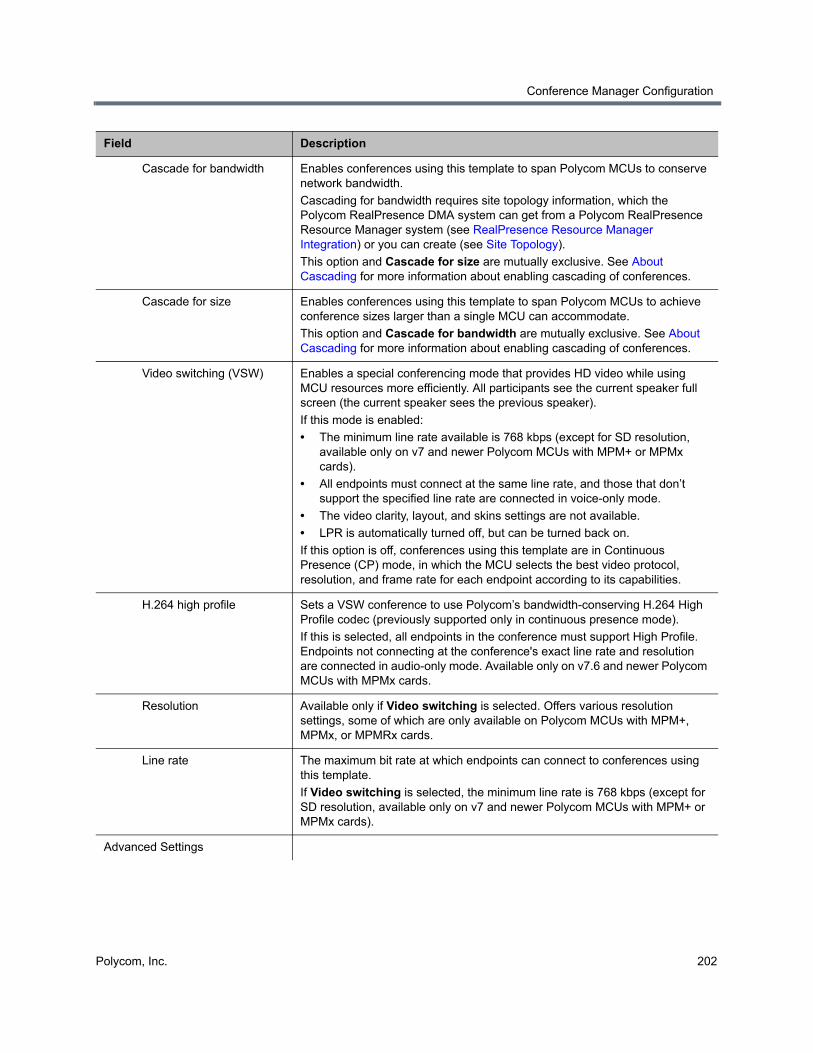
Conference Manager Configuration
Polycom, Inc. 202
Cascade for bandwidth Enables conferences using this template to span Polycom MCUs to conserve network bandwidth.
Cascading for bandwidth requires site topology information, which the Polycom RealPresence DMA system can get from a Polycom RealPresence Resource Manager system (see RealPresence Resource Manager Integration) or you can create (see Site Topology).
This option and Cascade for size are mutually exclusive. See About Cascading for more information about enabling cascading of conferences.
Cascade for size Enables conferences using this template to span Polycom MCUs to achieve conference sizes larger than a single MCU can accommodate.
This option and Cascade for bandwidth are mutually exclusive. See About Cascading for more information about enabling cascading of conferences.
Video switching (VSW) Enables a special conferencing mode that provides HD video while using MCU resources more efficiently. All participants see the current speaker full screen (the current speaker sees the previous speaker).
If this mode is enabled:
• The minimum line rate available is 768 kbps (except for SD resolution, available only on v7 and newer Polycom MCUs with MPM+ or MPMx cards).
• All endpoints must connect at the same line rate, and those that don’t support the specified line rate are connected in voice-only mode.
• The video clarity, layout, and skins settings are not available.
• LPR is automatically turned off, but can be turned back on.
If this option is off, conferences using this template are in Continuous Presence (CP) mode, in which the MCU selects the best video protocol, resolution, and frame rate for each endpoint according to its capabilities.
H.264 high profile Sets a VSW conference to use Polycom’s bandwidth-conserving H.264 High Profile codec (previously supported only in continuous presence mode).
If this is selected, all endpoints in the conference must support High Profile. Endpoints not connecting at the conference's exact line rate and resolution are connected in audio-only mode. Available only on v7.6 and newer Polycom MCUs with MPMx cards.
Resolution Available only if Video switching is selected. Offers various resolution settings, some of which are only available on Polycom MCUs with MPM+, MPMx, or MPMRx cards.
Line rate The maximum bit rate at which endpoints can connect to conferences using this template.
If Video switching is selected, the minimum line rate is 768 kbps (except for SD resolution, available only on v7 and newer Polycom MCUs with MPM+ or MPMx cards).
Advanced Settings
Field Description

Conference Manager Configuration
Polycom, Inc. 203
Encryption Specifies the media encryption setting for conferences using this template:
• No encryption — All endpoints join unencrypted.
• Encrypt when possible — Endpoints supporting encryption join encrypted; others join unencrypted.
• Encrypt all — Endpoints supporting encryption join encrypted; others can’t join.
Note: VMR dial-outs to H.323 endpoints from an encrypted RealPresence DMA system conference are unsupported and will not connect.
Note: Prior to v7.2, RMX MCUs supported only encryption settings of On and Off. If such an RMX is selected for a conference, the settings Encrypt when possible or Encrypt all are both converted to On.
Consult the MCU’s Administrator’s Guide for the version in question for detailed information about media encryption (SRTP).
Media encryption may be required in a maximum security environment.
LPR Enables Lost Packet Recovery for conferences using this template. LPR creates additional packets containing recovery information that can be used to reconstruct packets lost during transmission.
TIP compatibility Enables compatibility with Cisco’s Telepresence Interoperability Protocol, either for video only or for both video and content. Conferences can include both endpoints that don't support TIP and Cisco TelePresence® System (CTS) endpoints. If Prefer TIP is selected, TIP content is used for endpoints that support TIP, and non-TIP content is used with non-TIP endpoints.
Requires minimum line rate of 1024 kbps and HD resolution (720 or better). Available only on v7.6 and newer Polycom MCUs.
MS AVMCU cascade mode
When integrated with a Lync 2013 environment, controls behavior of the cascade link with the Lync 2013 AVMCU.
• Resource Optimized — The cascade link between the RealPresence DMA system and the Lync 2013 server’s AVMCU is capable of HD video resolutions, increasing MCU resource usage.
• Video Optimized — The cascade link between the RealPresence DMA system and the Lync 2013 server’s AVMCU is limited to SD video resolutions to conserve MCU resources.
FW NAT keep alive Specifies that when receiving calls through an SBC, the MCU should send media stream keep-alive messages to the SBC at the interval specified.
Interval (seconds) Specifies how often to send keep-alive messages.
Enable FECC When checked, enable Far End Camera Control for conference participants.
Exclusive content mode When checked, if a participant is broadcasting content, prevent other participants from interrupting with their own content while the current content stream is active.
Font for text over video (MPMx or newer)
Allows you to specify the font type for text displayed to participants in a conference. If using Default the system will display Heiti if a Chinese language is configured.
Note: This property only applies when the MCU is configured for multilingual operation with Chinese (Simplified or Traditional) selected.
Field Description
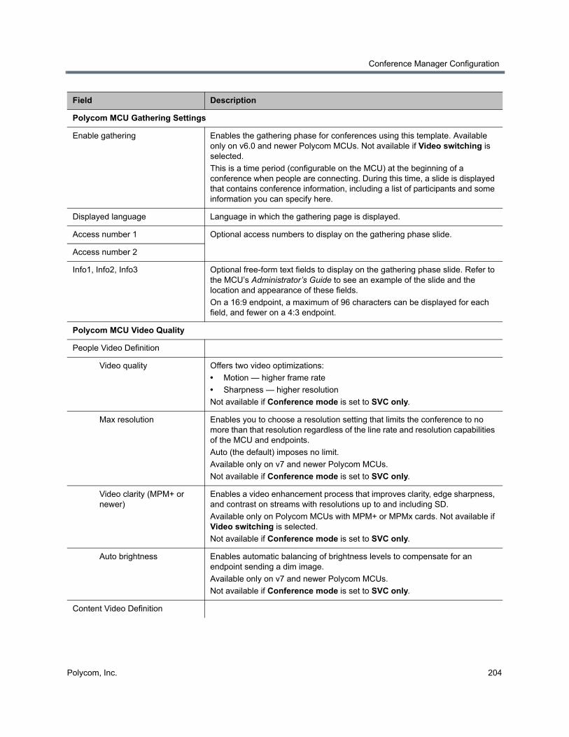
Conference Manager Configuration
Polycom, Inc. 204
Polycom MCU Gathering Settings
Enable gathering Enables the gathering phase for conferences using this template. Available only on v6.0 and newer Polycom MCUs. Not available if Video switching is selected.
This is a time period (configurable on the MCU) at the beginning of a conference when people are connecting. During this time, a slide is displayed that contains conference information, including a list of participants and some information you can specify here.
Displayed language Language in which the gathering page is displayed.
Access number 1 Optional access numbers to display on the gathering phase slide.
Access number 2
Info1, Info2, Info3 Optional free-form text fields to display on the gathering phase slide. Refer to the MCU’s Administrator’s Guide to see an example of the slide and the location and appearance of these fields.
On a 16:9 endpoint, a maximum of 96 characters can be displayed for each field, and fewer on a 4:3 endpoint.
Polycom MCU Video Quality
People Video Definition
Video quality Offers two video optimizations:
• Motion — higher frame rate
• Sharpness — higher resolution
Not available if Conference mode is set to SVC only.
Max resolution Enables you to choose a resolution setting that limits the conference to no more than that resolution regardless of the line rate and resolution capabilities of the MCU and endpoints.
Auto (the default) imposes no limit.
Available only on v7 and newer Polycom MCUs.
Not available if Conference mode is set to SVC only.
Video clarity (MPM+ or newer)
Enables a video enhancement process that improves clarity, edge sharpness, and contrast on streams with resolutions up to and including SD.
Available only on Polycom MCUs with MPM+ or MPMx cards. Not available if Video switching is selected.
Not available if Conference mode is set to SVC only.
Auto brightness Enables automatic balancing of brightness levels to compensate for an endpoint sending a dim image.
Available only on v7 and newer Polycom MCUs.
Not available if Conference mode is set to SVC only.
Content Video Definition
Field Description
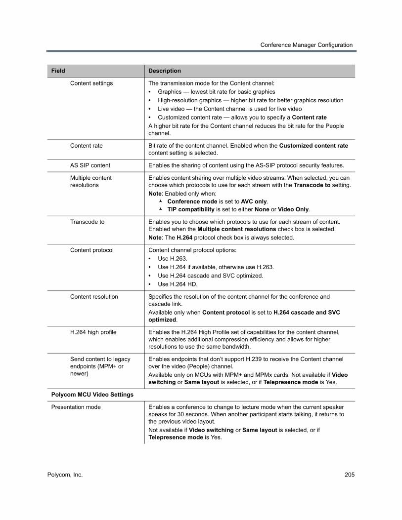
Conference Manager Configuration
Polycom, Inc. 205
Content settings The transmission mode for the Content channel:
• Graphics — lowest bit rate for basic graphics
• High-resolution graphics — higher bit rate for better graphics resolution
• Live video — the Content channel is used for live video
• Customized content rate — allows you to specify a Content rate
A higher bit rate for the Content channel reduces the bit rate for the People channel.
Content rate Bit rate of the content channel. Enabled when the Customized content rate content setting is selected.
AS SIP content Enables the sharing of content using the AS-SIP protocol security features.
Multiple content resolutions
Enables content sharing over multiple video streams. When selected, you can choose which protocols to use for each stream with the Transcode to setting.
Note: Enabled only when: Conference mode is set to AVC only. TIP compatibility is set to either None or Video Only.
Transcode to Enables you to choose which protocols to use for each stream of content. Enabled when the Multiple content resolutions check box is selected.
Note: The H.264 protocol check box is always selected.
Content protocol Content channel protocol options:
• Use H.263.
• Use H.264 if available, otherwise use H.263.
• Use H.264 cascade and SVC optimized.
• Use H.264 HD.
Content resolution Specifies the resolution of the content channel for the conference and cascade link.
Available only when Content protocol is set to H.264 cascade and SVC optimized.
H.264 high profile Enables the H.264 High Profile set of capabilities for the content channel, which enables additional compression efficiency and allows for higher resolutions to use the same bandwidth.
Send content to legacy endpoints (MPM+ or newer)
Enables endpoints that don’t support H.239 to receive the Content channel over the video (People) channel.
Available only on MCUs with MPM+ and MPMx cards. Not available if Video switching or Same layout is selected, or if Telepresence mode is Yes.
Polycom MCU Video Settings
Presentation mode Enables a conference to change to lecture mode when the current speaker speaks for 30 seconds. When another participant starts talking, it returns to the previous video layout.
Not available if Video switching or Same layout is selected, or if Telepresence mode is Yes.
Field Description
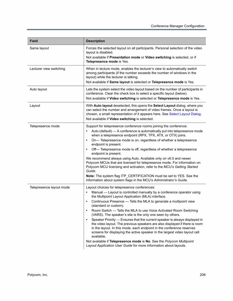
Conference Manager Configuration
Polycom, Inc. 206
Same layout Forces the selected layout on all participants. Personal selection of the video layout is disabled.
Not available if Presentation mode or Video switching is selected, or if Telepresence mode is Yes.
Lecturer view switching When in lecture mode, enables the lecturer’s view to automatically switch among participants (if the number exceeds the number of windows in the layout) while the lecturer is talking.
Not available if Same layout is selected or Telepresence mode is Yes.
Auto layout Lets the system select the video layout based on the number of participants in conference. Clear the check box to select a specific layout (below).
Not available if Video switching is selected or Telepresence mode is Yes.
Layout With Auto layout deselected, this opens the Select Layout dialog, where you can select the number and arrangement of video frames. Once a layout is chosen, a small representation of it appears here. See Select Layout Dialog.
Not available if Video switching is selected.
Telepresence mode Support for telepresence conference rooms joining the conference:
• Auto (default) — A conference is automatically put into telepresence mode when a telepresence endpoint (RPX, TPX, ATX, or OTX) joins.
• On— Telepresence mode is on, regardless of whether a telepresence endpoint is present.
• Off— Telepresence mode is off, regardless of whether a telepresence endpoint is present.
We recommend always using Auto. Available only on v6.0 and newer Polycom MCUs that are licensed for telepresence mode. For information on Polycom MCU licensing and activation, refer to the MCU’s Getting Started Guide.
Note: The system flag ITP_CERTIFICATION must be set to YES. See the information about system flags in the MCU’s Administrator’s Guide.
Telepresence layout mode Layout choices for telepresence conferences:
• Manual — Layout is controlled manually by a conference operator using the Multipoint Layout Application (MLA) interface.
• Continuous Presence — Tells the MLA to generate a multipoint view (standard or custom).
• Room Switch — Tells the MLA to use Voice Activated Room Switching (VARS). The speaker’s site is the only one seen by others.
• Speaker Priority — Ensures that the current speaker is always displayed in the video layout. The previous speakers are also displayed if there is room in the layout. In this mode, each endpoint in the conference reserves screens for displaying the active speaker in the largest video layout cell available.
Not available if Telepresence mode is No. See the Polycom Multipoint Layout Application User Guide for more information about layouts.
Field Description
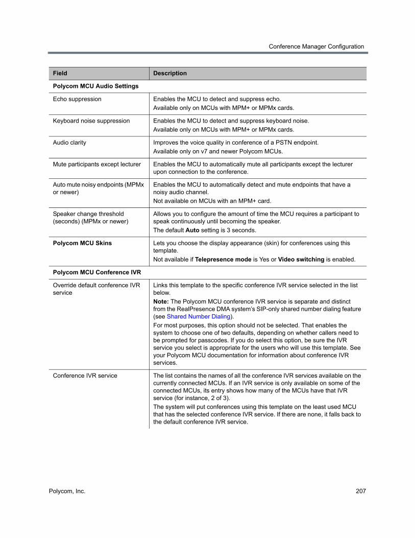
Conference Manager Configuration
Polycom, Inc. 207
Polycom MCU Audio Settings
Echo suppression Enables the MCU to detect and suppress echo.
Available only on MCUs with MPM+ or MPMx cards.
Keyboard noise suppression Enables the MCU to detect and suppress keyboard noise.
Available only on MCUs with MPM+ or MPMx cards.
Audio clarity Improves the voice quality in conference of a PSTN endpoint.
Available only on v7 and newer Polycom MCUs.
Mute participants except lecturer Enables the MCU to automatically mute all participants except the lecturer upon connection to the conference.
Auto mute noisy endpoints (MPMx or newer)
Enables the MCU to automatically detect and mute endpoints that have a noisy audio channel.
Not available on MCUs with an MPM+ card.
Speaker change threshold (seconds) (MPMx or newer)
Allows you to configure the amount of time the MCU requires a participant to speak continuously until becoming the speaker.
The default Auto setting is 3 seconds.
Polycom MCU Skins Lets you choose the display appearance (skin) for conferences using this template.
Not available if Telepresence mode is Yes or Video switching is enabled.
Polycom MCU Conference IVR
Override default conference IVR service
Links this template to the specific conference IVR service selected in the list below.
Note: The Polycom MCU conference IVR service is separate and distinct from the RealPresence DMA system’s SIP-only shared number dialing feature (see Shared Number Dialing).
For most purposes, this option should not be selected. That enables the system to choose one of two defaults, depending on whether callers need to be prompted for passcodes. If you do select this option, be sure the IVR service you select is appropriate for the users who will use this template. See your Polycom MCU documentation for information about conference IVR services.
Conference IVR service The list contains the names of all the conference IVR services available on the currently connected MCUs. If an IVR service is only available on some of the connected MCUs, its entry shows how many of the MCUs have that IVR service (for instance, 2 of 3).
The system will put conferences using this template on the least used MCU that has the selected conference IVR service. If there are none, it falls back to the default conference IVR service.
Field Description
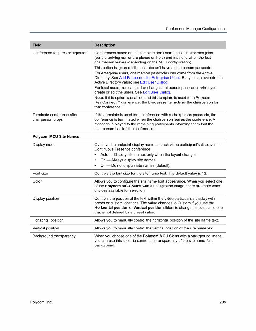
Conference Manager Configuration
Polycom, Inc. 208
Conference requires chairperson Conferences based on this template don’t start until a chairperson joins (callers arriving earlier are placed on hold) and may end when the last chairperson leaves (depending on the MCU configuration).
This option is ignored if the user doesn’t have a chairperson passcode.
For enterprise users, chairperson passcodes can come from the Active Directory. See Add Passcodes for Enterprise Users. But you can override the Active Directory value; see Edit User Dialog.
For local users, you can add or change chairperson passcodes when you create or edit the users. See Edit User Dialog.
Note: If this option is enabled and this template is used for a Polycom RealConnectTM conference, the Lync presenter acts as the chairperson for that conference.
Terminate conference after chairperson drops
If this template is used for a conference with a chairperson passcode, the conference is terminated when the chairperson leaves the conference. A message is played to the remaining participants informing them that the chairperson has left the conference.
Polycom MCU Site Names
Display mode Overlays the endpoint display name on each video participant’s display in a Continuous Presence conference:
• Auto — Display site names only when the layout changes.
• On — Always display site names.
• Off — Do not display site names (default).
Font size Controls the font size for the site name text. The default value is 12.
Color Allows you to configure the site name font appearance. When you select one of the Polycom MCU Skins with a background image, there are more color choices available for selection.
Display position Controls the position of the text within the video participant’s display with preset or custom locations. The value changes to Custom if you use the Horizontal position or Vertical position sliders to change the position to one that is not defined by a preset value.
Horizontal position Allows you to manually control the horizontal position of the site name text.
Vertical position Allows you to manually control the vertical position of the site name text.
Background transparency When you choose one of the Polycom MCU Skins with a background image, you can use this slider to control the transparency of the site name font background.
Field Description
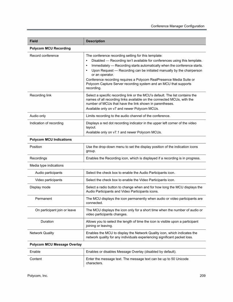
Conference Manager Configuration
Polycom, Inc. 209
Polycom MCU Recording
Record conference The conference recording setting for this template:
• Disabled — Recording isn’t available for conferences using this template.
• Immediately — Recording starts automatically when the conference starts.
• Upon Request — Recording can be initiated manually by the chairperson or an operator.
Conference recording requires a Polycom RealPresence Media Suite or Polycom Capture Server recording system and an MCU that supports recording.
Recording link Select a specific recording link or the MCU’s default. The list contains the names of all recording links available on the connected MCUs, with the number of MCUs that have the link shown in parentheses.
Available only on v7 and newer Polycom MCUs.
Audio only Limits recording to the audio channel of the conference.
Indication of recording Displays a red dot recording indicator in the upper left corner of the video layout.
Available only on v7.1 and newer Polycom MCUs.
Polycom MCU Indications
Position Use the drop-down menu to set the display position of the indication icons group.
Recordings Enables the Recording icon, which is displayed if a recording is in progress.
Media type indications
Audio participants Select the check box to enable the Audio Participants icon.
Video participants Select the check box to enable the Video Participants icon.
Display mode Select a radio button to change when and for how long the MCU displays the Audio Participants and Video Participants icons.
Permanent The MCU displays the icon permanently when audio or video participants are connected.
On participant join or leave The MCU displays the icon only for a short time when the number of audio or video participants changes.
Duration Allows you to select the length of time the icon is visible upon a participant joining or leaving.
Network Quality Enables the MCU to display the Network Quality icon, which indicates the network quality for any individuals experiencing significant packet loss.
Polycom MCU Message Overlay
Enable Enables or disables Message Overlay (disabled by default).
Content Enter the message text. The message text can be up to 50 Unicode characters.
Field Description
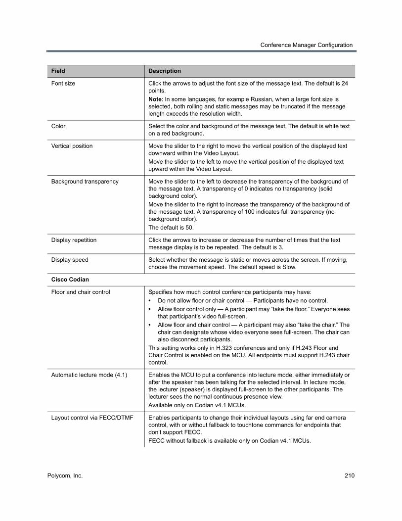
Conference Manager Configuration
Polycom, Inc. 210
Font size Click the arrows to adjust the font size of the message text. The default is 24 points.
Note: In some languages, for example Russian, when a large font size is selected, both rolling and static messages may be truncated if the message length exceeds the resolution width.
Color Select the color and background of the message text. The default is white text on a red background.
Vertical position Move the slider to the right to move the vertical position of the displayed text downward within the Video Layout.
Move the slider to the left to move the vertical position of the displayed text upward within the Video Layout.
Background transparency Move the slider to the left to decrease the transparency of the background of the message text. A transparency of 0 indicates no transparency (solid background color).
Move the slider to the right to increase the transparency of the background of the message text. A transparency of 100 indicates full transparency (no background color).
The default is 50.
Display repetition Click the arrows to increase or decrease the number of times that the text message display is to be repeated. The default is 3.
Display speed Select whether the message is static or moves across the screen. If moving, choose the movement speed. The default speed is Slow.
Cisco Codian
Floor and chair control Specifies how much control conference participants may have:
• Do not allow floor or chair control — Participants have no control.
• Allow floor control only — A participant may “take the floor.” Everyone sees that participant’s video full-screen.
• Allow floor and chair control — A participant may also “take the chair.” The chair can designate whose video everyone sees full-screen. The chair can also disconnect participants.
This setting works only in H.323 conferences and only if H.243 Floor and Chair Control is enabled on the MCU. All endpoints must support H.243 chair control.
Automatic lecture mode (4.1) Enables the MCU to put a conference into lecture mode, either immediately or after the speaker has been talking for the selected interval. In lecture mode, the lecturer (speaker) is displayed full-screen to the other participants. The lecturer sees the normal continuous presence view.
Available only on Codian v4.1 MCUs.
Layout control via FECC/DTMF Enables participants to change their individual layouts using far end camera control, with or without fallback to touchtone commands for endpoints that don’t support FECC.
FECC without fallback is available only on Codian v4.1 MCUs.
Field Description
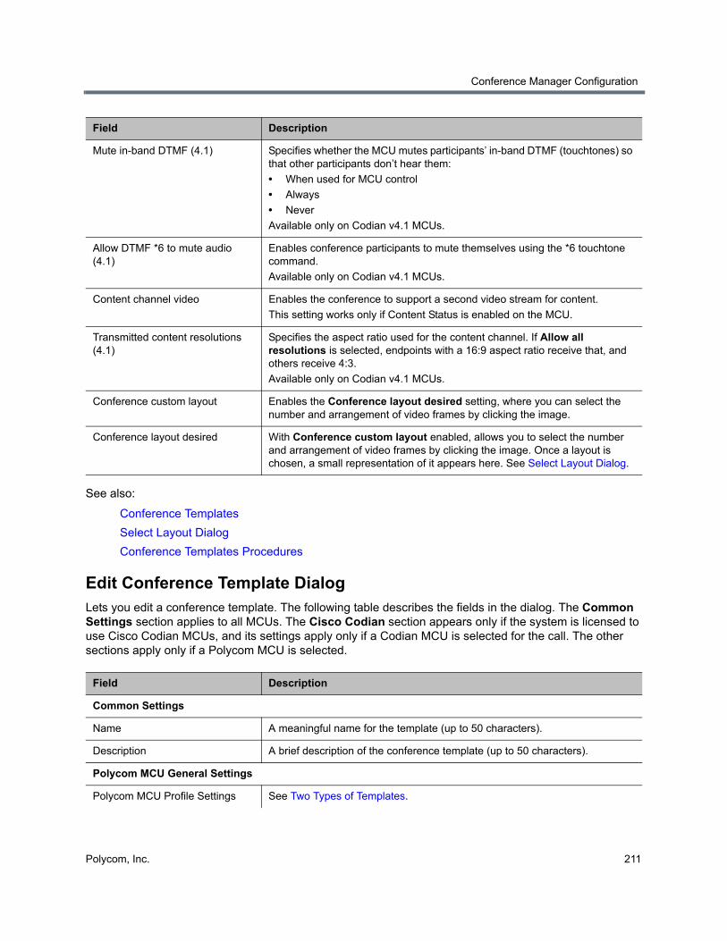
Conference Manager Configuration
Polycom, Inc. 211
See also:
Conference Templates
Select Layout Dialog
Conference Templates Procedures
Edit Conference Template DialogLets you edit a conference template. The following table describes the fields in the dialog. The Common Settings section applies to all MCUs. The Cisco Codian section appears only if the system is licensed to use Cisco Codian MCUs, and its settings apply only if a Codian MCU is selected for the call. The other sections apply only if a Polycom MCU is selected.
Mute in-band DTMF (4.1) Specifies whether the MCU mutes participants’ in-band DTMF (touchtones) so that other participants don’t hear them:
• When used for MCU control
• Always
• Never
Available only on Codian v4.1 MCUs.
Allow DTMF *6 to mute audio (4.1)
Enables conference participants to mute themselves using the *6 touchtone command.
Available only on Codian v4.1 MCUs.
Content channel video Enables the conference to support a second video stream for content.
This setting works only if Content Status is enabled on the MCU.
Transmitted content resolutions (4.1)
Specifies the aspect ratio used for the content channel. If Allow all resolutions is selected, endpoints with a 16:9 aspect ratio receive that, and others receive 4:3.
Available only on Codian v4.1 MCUs.
Conference custom layout Enables the Conference layout desired setting, where you can select the number and arrangement of video frames by clicking the image.
Conference layout desired With Conference custom layout enabled, allows you to select the number and arrangement of video frames by clicking the image. Once a layout is chosen, a small representation of it appears here. See Select Layout Dialog.
Field Description
Common Settings
Name A meaningful name for the template (up to 50 characters).
Description A brief description of the conference template (up to 50 characters).
Polycom MCU General Settings
Polycom MCU Profile Settings See Two Types of Templates.
Field Description
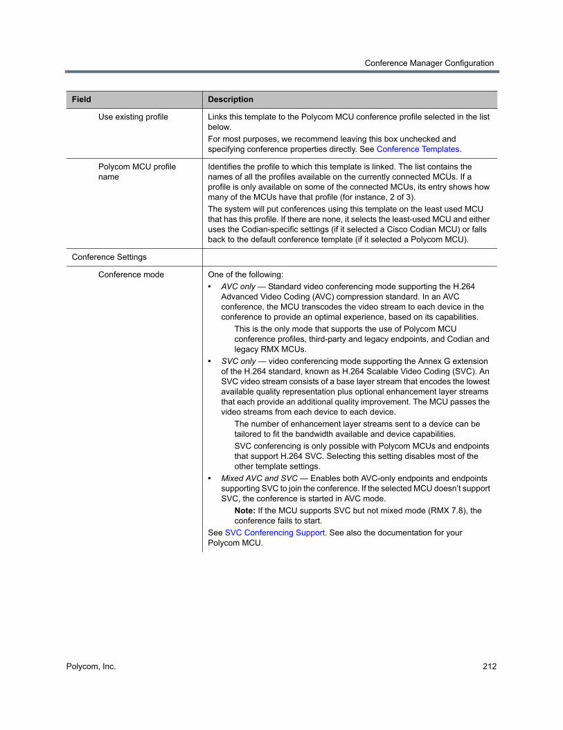
Conference Manager Configuration
Polycom, Inc. 212
Use existing profile Links this template to the Polycom MCU conference profile selected in the list below.
For most purposes, we recommend leaving this box unchecked and specifying conference properties directly. See Conference Templates.
Polycom MCU profile name
Identifies the profile to which this template is linked. The list contains the names of all the profiles available on the currently connected MCUs. If a profile is only available on some of the connected MCUs, its entry shows how many of the MCUs have that profile (for instance, 2 of 3).
The system will put conferences using this template on the least used MCU that has this profile. If there are none, it selects the least-used MCU and either uses the Codian-specific settings (if it selected a Cisco Codian MCU) or falls back to the default conference template (if it selected a Polycom MCU).
Conference Settings
Conference mode One of the following:
• AVC only — Standard video conferencing mode supporting the H.264 Advanced Video Coding (AVC) compression standard. In an AVC conference, the MCU transcodes the video stream to each device in the conference to provide an optimal experience, based on its capabilities.
This is the only mode that supports the use of Polycom MCU conference profiles, third-party and legacy endpoints, and Codian and legacy RMX MCUs.
• SVC only — video conferencing mode supporting the Annex G extension of the H.264 standard, known as H.264 Scalable Video Coding (SVC). An SVC video stream consists of a base layer stream that encodes the lowest available quality representation plus optional enhancement layer streams that each provide an additional quality improvement. The MCU passes the video streams from each device to each device.
The number of enhancement layer streams sent to a device can be tailored to fit the bandwidth available and device capabilities.
SVC conferencing is only possible with Polycom MCUs and endpoints that support H.264 SVC. Selecting this setting disables most of the other template settings.
• Mixed AVC and SVC — Enables both AVC-only endpoints and endpoints supporting SVC to join the conference. If the selected MCU doesn’t support SVC, the conference is started in AVC mode.
Note: If the MCU supports SVC but not mixed mode (RMX 7.8), the conference fails to start.
See SVC Conferencing Support. See also the documentation for your Polycom MCU.
Field Description
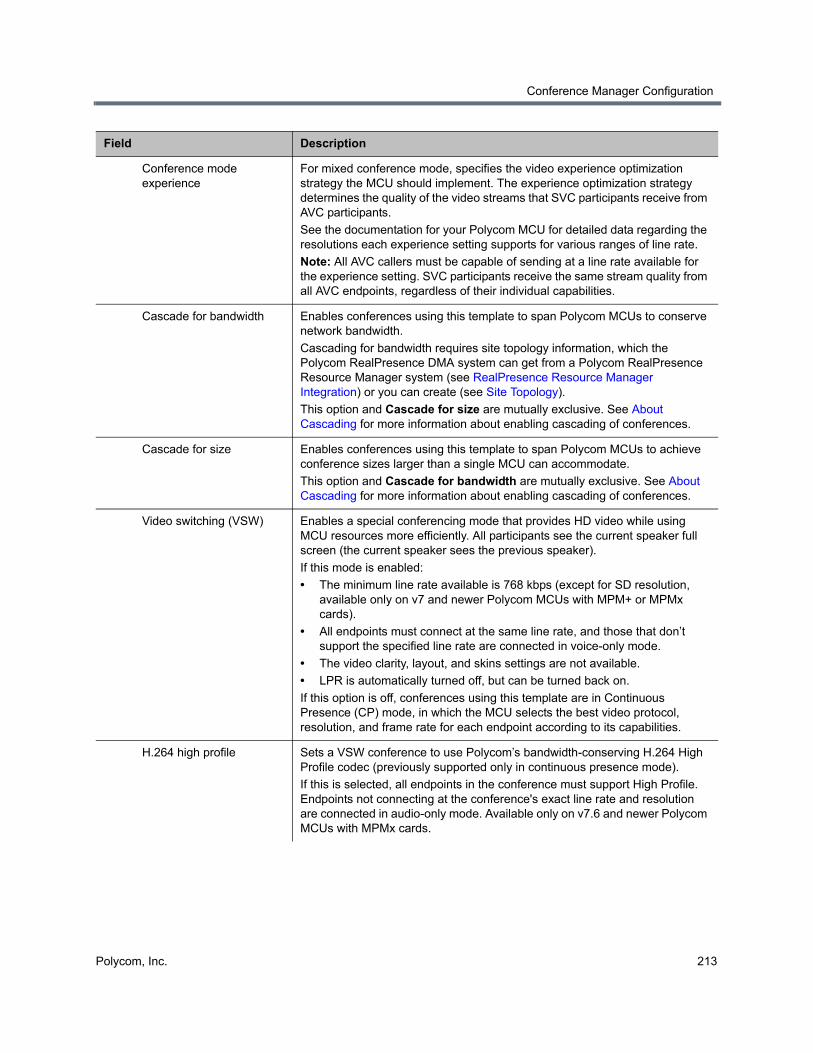
Conference Manager Configuration
Polycom, Inc. 213
Conference mode experience
For mixed conference mode, specifies the video experience optimization strategy the MCU should implement. The experience optimization strategy determines the quality of the video streams that SVC participants receive from AVC participants.
See the documentation for your Polycom MCU for detailed data regarding the resolutions each experience setting supports for various ranges of line rate.
Note: All AVC callers must be capable of sending at a line rate available for the experience setting. SVC participants receive the same stream quality from all AVC endpoints, regardless of their individual capabilities.
Cascade for bandwidth Enables conferences using this template to span Polycom MCUs to conserve network bandwidth.
Cascading for bandwidth requires site topology information, which the Polycom RealPresence DMA system can get from a Polycom RealPresence Resource Manager system (see RealPresence Resource Manager Integration) or you can create (see Site Topology).
This option and Cascade for size are mutually exclusive. See About Cascading for more information about enabling cascading of conferences.
Cascade for size Enables conferences using this template to span Polycom MCUs to achieve conference sizes larger than a single MCU can accommodate.
This option and Cascade for bandwidth are mutually exclusive. See About Cascading for more information about enabling cascading of conferences.
Video switching (VSW) Enables a special conferencing mode that provides HD video while using MCU resources more efficiently. All participants see the current speaker full screen (the current speaker sees the previous speaker).
If this mode is enabled:
• The minimum line rate available is 768 kbps (except for SD resolution, available only on v7 and newer Polycom MCUs with MPM+ or MPMx cards).
• All endpoints must connect at the same line rate, and those that don’t support the specified line rate are connected in voice-only mode.
• The video clarity, layout, and skins settings are not available.
• LPR is automatically turned off, but can be turned back on.
If this option is off, conferences using this template are in Continuous Presence (CP) mode, in which the MCU selects the best video protocol, resolution, and frame rate for each endpoint according to its capabilities.
H.264 high profile Sets a VSW conference to use Polycom’s bandwidth-conserving H.264 High Profile codec (previously supported only in continuous presence mode).
If this is selected, all endpoints in the conference must support High Profile. Endpoints not connecting at the conference's exact line rate and resolution are connected in audio-only mode. Available only on v7.6 and newer Polycom MCUs with MPMx cards.
Field Description
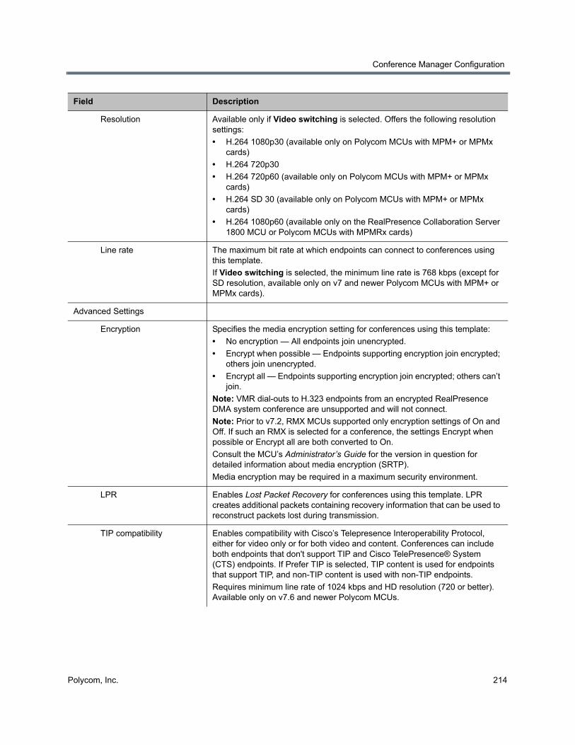
Conference Manager Configuration
Polycom, Inc. 214
Resolution Available only if Video switching is selected. Offers the following resolution settings:
• H.264 1080p30 (available only on Polycom MCUs with MPM+ or MPMx cards)
• H.264 720p30
• H.264 720p60 (available only on Polycom MCUs with MPM+ or MPMx cards)
• H.264 SD 30 (available only on Polycom MCUs with MPM+ or MPMx cards)
• H.264 1080p60 (available only on the RealPresence Collaboration Server 1800 MCU or Polycom MCUs with MPMRx cards)
Line rate The maximum bit rate at which endpoints can connect to conferences using this template.
If Video switching is selected, the minimum line rate is 768 kbps (except for SD resolution, available only on v7 and newer Polycom MCUs with MPM+ or MPMx cards).
Advanced Settings
Encryption Specifies the media encryption setting for conferences using this template:
• No encryption — All endpoints join unencrypted.
• Encrypt when possible — Endpoints supporting encryption join encrypted; others join unencrypted.
• Encrypt all — Endpoints supporting encryption join encrypted; others can’t join.
Note: VMR dial-outs to H.323 endpoints from an encrypted RealPresence DMA system conference are unsupported and will not connect.
Note: Prior to v7.2, RMX MCUs supported only encryption settings of On and Off. If such an RMX is selected for a conference, the settings Encrypt when possible or Encrypt all are both converted to On.
Consult the MCU’s Administrator’s Guide for the version in question for detailed information about media encryption (SRTP).
Media encryption may be required in a maximum security environment.
LPR Enables Lost Packet Recovery for conferences using this template. LPR creates additional packets containing recovery information that can be used to reconstruct packets lost during transmission.
TIP compatibility Enables compatibility with Cisco’s Telepresence Interoperability Protocol, either for video only or for both video and content. Conferences can include both endpoints that don't support TIP and Cisco TelePresence® System (CTS) endpoints. If Prefer TIP is selected, TIP content is used for endpoints that support TIP, and non-TIP content is used with non-TIP endpoints.
Requires minimum line rate of 1024 kbps and HD resolution (720 or better). Available only on v7.6 and newer Polycom MCUs.
Field Description
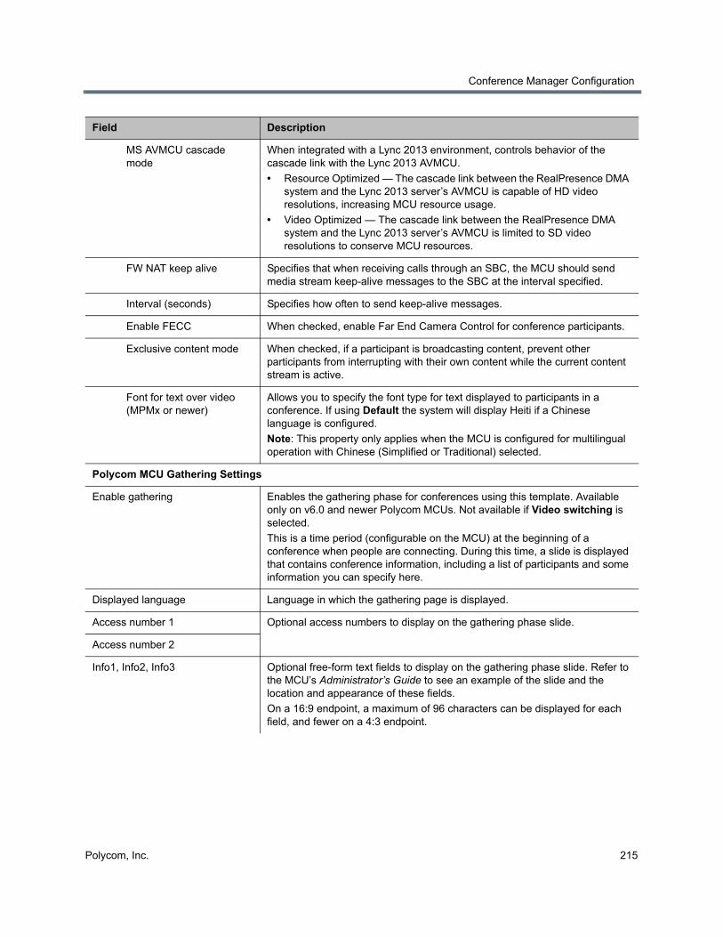
Conference Manager Configuration
Polycom, Inc. 215
MS AVMCU cascade mode
When integrated with a Lync 2013 environment, controls behavior of the cascade link with the Lync 2013 AVMCU.
• Resource Optimized — The cascade link between the RealPresence DMA system and the Lync 2013 server’s AVMCU is capable of HD video resolutions, increasing MCU resource usage.
• Video Optimized — The cascade link between the RealPresence DMA system and the Lync 2013 server’s AVMCU is limited to SD video resolutions to conserve MCU resources.
FW NAT keep alive Specifies that when receiving calls through an SBC, the MCU should send media stream keep-alive messages to the SBC at the interval specified.
Interval (seconds) Specifies how often to send keep-alive messages.
Enable FECC When checked, enable Far End Camera Control for conference participants.
Exclusive content mode When checked, if a participant is broadcasting content, prevent other participants from interrupting with their own content while the current content stream is active.
Font for text over video (MPMx or newer)
Allows you to specify the font type for text displayed to participants in a conference. If using Default the system will display Heiti if a Chinese language is configured.
Note: This property only applies when the MCU is configured for multilingual operation with Chinese (Simplified or Traditional) selected.
Polycom MCU Gathering Settings
Enable gathering Enables the gathering phase for conferences using this template. Available only on v6.0 and newer Polycom MCUs. Not available if Video switching is selected.
This is a time period (configurable on the MCU) at the beginning of a conference when people are connecting. During this time, a slide is displayed that contains conference information, including a list of participants and some information you can specify here.
Displayed language Language in which the gathering page is displayed.
Access number 1 Optional access numbers to display on the gathering phase slide.
Access number 2
Info1, Info2, Info3 Optional free-form text fields to display on the gathering phase slide. Refer to the MCU’s Administrator’s Guide to see an example of the slide and the location and appearance of these fields.
On a 16:9 endpoint, a maximum of 96 characters can be displayed for each field, and fewer on a 4:3 endpoint.
Field Description
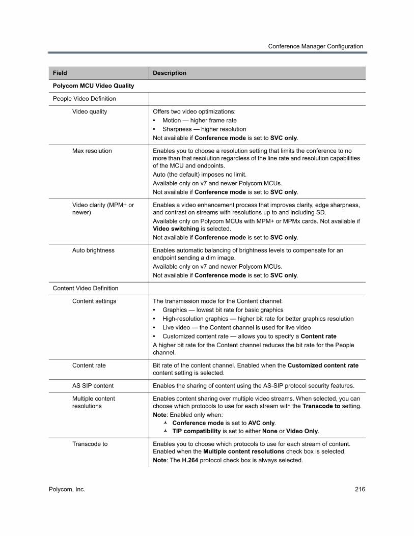
Conference Manager Configuration
Polycom, Inc. 216
Polycom MCU Video Quality
People Video Definition
Video quality Offers two video optimizations:
• Motion — higher frame rate
• Sharpness — higher resolution
Not available if Conference mode is set to SVC only.
Max resolution Enables you to choose a resolution setting that limits the conference to no more than that resolution regardless of the line rate and resolution capabilities of the MCU and endpoints.
Auto (the default) imposes no limit.
Available only on v7 and newer Polycom MCUs.
Not available if Conference mode is set to SVC only.
Video clarity (MPM+ or newer)
Enables a video enhancement process that improves clarity, edge sharpness, and contrast on streams with resolutions up to and including SD.
Available only on Polycom MCUs with MPM+ or MPMx cards. Not available if Video switching is selected.
Not available if Conference mode is set to SVC only.
Auto brightness Enables automatic balancing of brightness levels to compensate for an endpoint sending a dim image.
Available only on v7 and newer Polycom MCUs.
Not available if Conference mode is set to SVC only.
Content Video Definition
Content settings The transmission mode for the Content channel:
• Graphics — lowest bit rate for basic graphics
• High-resolution graphics — higher bit rate for better graphics resolution
• Live video — the Content channel is used for live video
• Customized content rate — allows you to specify a Content rate
A higher bit rate for the Content channel reduces the bit rate for the People channel.
Content rate Bit rate of the content channel. Enabled when the Customized content rate content setting is selected.
AS SIP content Enables the sharing of content using the AS-SIP protocol security features.
Multiple content resolutions
Enables content sharing over multiple video streams. When selected, you can choose which protocols to use for each stream with the Transcode to setting.
Note: Enabled only when: Conference mode is set to AVC only. TIP compatibility is set to either None or Video Only.
Transcode to Enables you to choose which protocols to use for each stream of content. Enabled when the Multiple content resolutions check box is selected.
Note: The H.264 protocol check box is always selected.
Field Description

Conference Manager Configuration
Polycom, Inc. 217
Content protocol Content channel protocol options:
• Use H.263.
• Use H.264 if available, otherwise use H.263.
• Use H.264 cascade and SVC optimized.
• Use H.264 HD.
Content resolution Specifies the resolution of the content channel for the conference and cascade link.
Available only when Content protocol is set to H.264 cascade and SVC optimized.
H.264 high profile Enables the H.264 High Profile set of capabilities for the content channel, which enables additional compression efficiency and allows for higher resolutions to use the same bandwidth.
Send content to legacy endpoints (MPM+ or newer)
Enables endpoints that don’t support H.239 to receive the Content channel over the video (People) channel.
Available only on MCUs with MPM+ and MPMx cards. Not available if Video switching or Same layout is selected, or if Telepresence mode is Yes.
Polycom MCU Video Settings
Presentation mode Enables a conference to change to lecture mode when the current speaker speaks for 30 seconds. When another participant starts talking, it returns to the previous video layout.
Not available if Video switching or Same layout is selected, or if Telepresence mode is Yes.
Same layout Forces the selected layout on all participants. Personal selection of the video layout is disabled.
Not available if Presentation mode or Video switching is selected, or if Telepresence mode is Yes.
Lecturer view switching When in lecture mode, enables the lecturer’s view to automatically switch among participants (if the number exceeds the number of windows in the layout) while the lecturer is talking.
Not available if Same layout is selected or Telepresence mode is Yes.
Auto layout Lets the system select the video layout based on the number of participants in conference. Clear the check box to select a specific layout (below).
Not available if Video switching is selected or Telepresence mode is Yes.
Layout With Auto layout deselected, this opens the Select Layout dialog, where you can select the number and arrangement of video frames. Once a layout is chosen, a small representation of it appears here. See Select Layout Dialog.
Not available if Video switching is selected.
Field Description
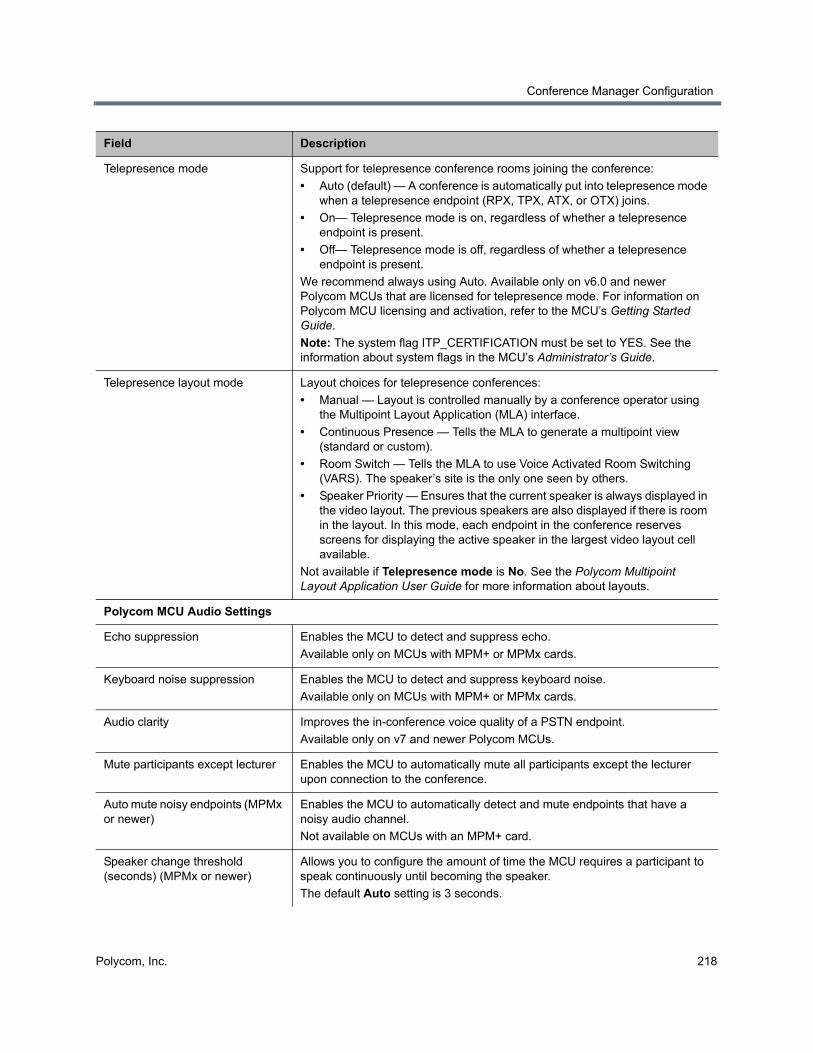
Conference Manager Configuration
Polycom, Inc. 218
Telepresence mode Support for telepresence conference rooms joining the conference:
• Auto (default) — A conference is automatically put into telepresence mode when a telepresence endpoint (RPX, TPX, ATX, or OTX) joins.
• On— Telepresence mode is on, regardless of whether a telepresence endpoint is present.
• Off— Telepresence mode is off, regardless of whether a telepresence endpoint is present.
We recommend always using Auto. Available only on v6.0 and newer Polycom MCUs that are licensed for telepresence mode. For information on Polycom MCU licensing and activation, refer to the MCU’s Getting Started Guide.
Note: The system flag ITP_CERTIFICATION must be set to YES. See the information about system flags in the MCU’s Administrator’s Guide.
Telepresence layout mode Layout choices for telepresence conferences:
• Manual — Layout is controlled manually by a conference operator using the Multipoint Layout Application (MLA) interface.
• Continuous Presence — Tells the MLA to generate a multipoint view (standard or custom).
• Room Switch — Tells the MLA to use Voice Activated Room Switching (VARS). The speaker’s site is the only one seen by others.
• Speaker Priority — Ensures that the current speaker is always displayed in the video layout. The previous speakers are also displayed if there is room in the layout. In this mode, each endpoint in the conference reserves screens for displaying the active speaker in the largest video layout cell available.
Not available if Telepresence mode is No. See the Polycom Multipoint Layout Application User Guide for more information about layouts.
Polycom MCU Audio Settings
Echo suppression Enables the MCU to detect and suppress echo.
Available only on MCUs with MPM+ or MPMx cards.
Keyboard noise suppression Enables the MCU to detect and suppress keyboard noise.
Available only on MCUs with MPM+ or MPMx cards.
Audio clarity Improves the in-conference voice quality of a PSTN endpoint.
Available only on v7 and newer Polycom MCUs.
Mute participants except lecturer Enables the MCU to automatically mute all participants except the lecturer upon connection to the conference.
Auto mute noisy endpoints (MPMx or newer)
Enables the MCU to automatically detect and mute endpoints that have a noisy audio channel.
Not available on MCUs with an MPM+ card.
Speaker change threshold (seconds) (MPMx or newer)
Allows you to configure the amount of time the MCU requires a participant to speak continuously until becoming the speaker.
The default Auto setting is 3 seconds.
Field Description
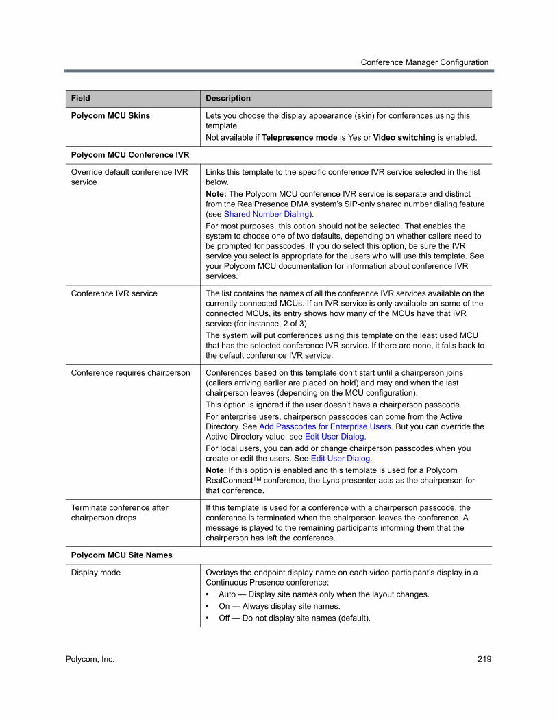
Conference Manager Configuration
Polycom, Inc. 219
Polycom MCU Skins Lets you choose the display appearance (skin) for conferences using this template.
Not available if Telepresence mode is Yes or Video switching is enabled.
Polycom MCU Conference IVR
Override default conference IVR service
Links this template to the specific conference IVR service selected in the list below.
Note: The Polycom MCU conference IVR service is separate and distinct from the RealPresence DMA system’s SIP-only shared number dialing feature (see Shared Number Dialing).
For most purposes, this option should not be selected. That enables the system to choose one of two defaults, depending on whether callers need to be prompted for passcodes. If you do select this option, be sure the IVR service you select is appropriate for the users who will use this template. See your Polycom MCU documentation for information about conference IVR services.
Conference IVR service The list contains the names of all the conference IVR services available on the currently connected MCUs. If an IVR service is only available on some of the connected MCUs, its entry shows how many of the MCUs have that IVR service (for instance, 2 of 3).
The system will put conferences using this template on the least used MCU that has the selected conference IVR service. If there are none, it falls back to the default conference IVR service.
Conference requires chairperson Conferences based on this template don’t start until a chairperson joins (callers arriving earlier are placed on hold) and may end when the last chairperson leaves (depending on the MCU configuration).
This option is ignored if the user doesn’t have a chairperson passcode.
For enterprise users, chairperson passcodes can come from the Active Directory. See Add Passcodes for Enterprise Users. But you can override the Active Directory value; see Edit User Dialog.
For local users, you can add or change chairperson passcodes when you create or edit the users. See Edit User Dialog.
Note: If this option is enabled and this template is used for a Polycom RealConnectTM conference, the Lync presenter acts as the chairperson for that conference.
Terminate conference after chairperson drops
If this template is used for a conference with a chairperson passcode, the conference is terminated when the chairperson leaves the conference. A message is played to the remaining participants informing them that the chairperson has left the conference.
Polycom MCU Site Names
Display mode Overlays the endpoint display name on each video participant’s display in a Continuous Presence conference:
• Auto — Display site names only when the layout changes.
• On — Always display site names.
• Off — Do not display site names (default).
Field Description
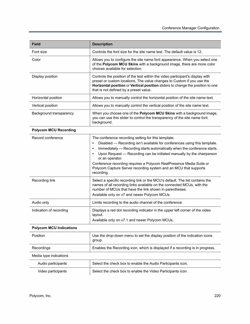
Conference Manager Configuration
Polycom, Inc. 220
Font size Controls the font size for the site name text. The default value is 12.
Color Allows you to configure the site name font appearance. When you select one of the Polycom MCU Skins with a background image, there are more color choices available for selection.
Display position Controls the position of the text within the video participant’s display with preset or custom locations. The value changes to Custom if you use the Horizontal position or Vertical position sliders to change the position to one that is not defined by a preset value.
Horizontal position Allows you to manually control the horizontal position of the site name text.
Vertical position Allows you to manually control the vertical position of the site name text.
Background transparency When you choose one of the Polycom MCU Skins with a background image, you can use this slider to control the transparency of the site name font background.
Polycom MCU Recording
Record conference The conference recording setting for this template:
• Disabled — Recording isn’t available for conferences using this template.
• Immediately — Recording starts automatically when the conference starts.
• Upon Request — Recording can be initiated manually by the chairperson or an operator.
Conference recording requires a Polycom RealPresence Media Suite or Polycom Capture Server recording system and an MCU that supports recording.
Recording link Select a specific recording link or the MCU’s default. The list contains the names of all recording links available on the connected MCUs, with the number of MCUs that have the link shown in parentheses.
Available only on v7 and newer Polycom MCUs.
Audio only Limits recording to the audio channel of the conference.
Indication of recording Displays a red dot recording indicator in the upper left corner of the video layout.
Available only on v7.1 and newer Polycom MCUs.
Polycom MCU Indications
Position Use the drop-down menu to set the display position of the indication icons group.
Recordings Enables the Recording icon, which is displayed if a recording is in progress.
Media type indications
Audio participants Select the check box to enable the Audio Participants icon.
Video participants Select the check box to enable the Video Participants icon.
Field Description
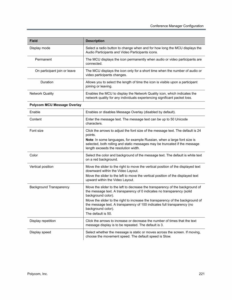
Conference Manager Configuration
Polycom, Inc. 221
Display mode Select a radio button to change when and for how long the MCU displays the Audio Participants and Video Participants icons.
Permanent The MCU displays the icon permanently when audio or video participants are connected.
On participant join or leave The MCU displays the icon only for a short time when the number of audio or video participants changes.
Duration Allows you to select the length of time the icon is visible upon a participant joining or leaving.
Network Quality Enables the MCU to display the Network Quality icon, which indicates the network quality for any individuals experiencing significant packet loss.
Polycom MCU Message Overlay
Enable Enables or disables Message Overlay (disabled by default).
Content Enter the message text. The message text can be up to 50 Unicode characters.
Font size Click the arrows to adjust the font size of the message text. The default is 24 points.
Note: In some languages, for example Russian, when a large font size is selected, both rolling and static messages may be truncated if the message length exceeds the resolution width.
Color Select the color and background of the message text. The default is white text on a red background.
Vertical position Move the slider to the right to move the vertical position of the displayed text downward within the Video Layout.
Move the slider to the left to move the vertical position of the displayed text upward within the Video Layout.
Background Transparency Move the slider to the left to decrease the transparency of the background of the message text. A transparency of 0 indicates no transparency (solid background color).
Move the slider to the right to increase the transparency of the background of the message text. A transparency of 100 indicates full transparency (no background color).
The default is 50.
Display repetition Click the arrows to increase or decrease the number of times that the text message display is to be repeated. The default is 3.
Display speed Select whether the message is static or moves across the screen. If moving, choose the movement speed. The default speed is Slow.
Field Description
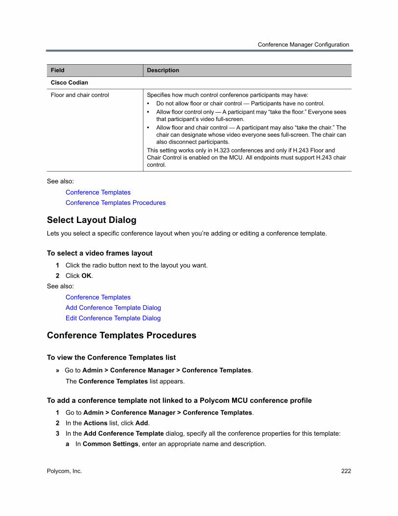
Conference Manager Configuration
Polycom, Inc. 222
See also:
Conference Templates
Conference Templates Procedures
Select Layout DialogLets you select a specific conference layout when you’re adding or editing a conference template.
To select a video frames layout
1 Click the radio button next to the layout you want.
2 Click OK.
See also:
Conference Templates
Add Conference Template Dialog
Edit Conference Template Dialog
Conference Templates Procedures
To view the Conference Templates list
» Go to Admin > Conference Manager > Conference Templates.
The Conference Templates list appears.
To add a conference template not linked to a Polycom MCU conference profile
1 Go to Admin > Conference Manager > Conference Templates.
2 In the Actions list, click Add.
3 In the Add Conference Template dialog, specify all the conference properties for this template:
a In Common Settings, enter an appropriate name and description.
Cisco Codian
Floor and chair control Specifies how much control conference participants may have:
• Do not allow floor or chair control — Participants have no control.
• Allow floor control only — A participant may “take the floor.” Everyone sees that participant’s video full-screen.
• Allow floor and chair control — A participant may also “take the chair.” The chair can designate whose video everyone sees full-screen. The chair can also disconnect participants.
This setting works only in H.323 conferences and only if H.243 Floor and Chair Control is enabled on the MCU. All endpoints must support H.243 chair control.
Field Description
Conference Manager Configuration
Polycom, Inc. 223
b Complete the remaining sections as desired. See Add Conference Template Dialog.
4 Click OK.
The new template appears in the Conference Templates list.
To add a conference template linked to a Polycom MCU conference profile
1 Go to Admin > Conference Manager > Conference Templates.
2 In the Actions list, click Add.
3 In the Add Conference Template dialog, specify all the conference properties for this template:
a In Common Settings, enter an appropriate name and description.
b Click the Polycom MCU General Settings tab.
c Check Use existing profile and select the one you want from the Polycom MCU profile name list.
The list contains the profiles available on the Polycom MCUs that have been added to the Polycom RealPresence DMA system. If no MCUs have been added to the system, the list is disabled.
4 Click OK.
The new template appears in the Conference Templates list.
To edit a conference template
1 Go to Admin > Conference Manager > Conference Templates.
2 In the Conference Templates list, select the template of interest, and in the Actions list, click Edit.
3 In the Edit Conference Template dialog, edit the settings as desired. See Edit Conference Template Dialog.
4 Click OK.
The template changes appear in the Conference Templates list.
To change a conference template’s priority
1 Go to Admin > Conference Manager > Conference Templates.
2 On the Conference Templates list, select the template whose priority you want to change.
3 In the Actions list, select Move Up or Move Down, depending on whether you want to increase or decrease the template’s priority ranking.
When a user is associated with multiple templates, the system uses the highest priority template. We recommend moving the system default template to the bottom of the list.
4 Repeat until the template has the desired ranking.
To delete a conference template
1 Go to Admin > Conference Manager > Conference Templates.
2 In the Conference Templates list, select the template you want to delete, and in the Actions list, click Delete.
Conference Manager Configuration
Polycom, Inc. 224
3 When asked to confirm that you want to delete the template, click Yes.
Any conference rooms or enterprise groups that used the template are reset to use the system default template.
See also:
Conference Templates
Add Conference Template Dialog
Edit Conference Template Dialog
External Lync SystemsWhen you define an external Lync system, your local Polycom infrastructure gains the ability to connect to a remote Lync deployment and start or join RealConnectTM conferences on that system. An external Lync system is a Lync deployment located at a remote site that has a federated relationship with your Lync deployment.
Microsoft Lync systems configured as external SIP peers enable RealConnectTM conferencing for Lync deployments within your network. External Lync systems extend that capability to Lync deployments outside of your network.
When the RealPresence DMA system routes a call to an external Lync system, it uses the prefix defined for the external Lync system to determine which external Lync system to use. It then selects a Polycom MCU to host the conference and contact the external Lync system’s Conference Auto Attendant (CAA) service. The RealPresence DMA system selects an Active Directory callback contact and passes it to the selected MCU. The Lync AVMCU calls the local MCU to establish a cascade link, joining the local MCU to the conference. The MCU uses an the callback contact to communicate with the local and external Lync systems, ensuring that the call is forwarded properly from the remote AVMCU to the local MCU.
Due to the nature of interacting with the external Lync system’s CAA service, there may be a delay of up to 20 seconds before participants are added to the conference they dialed.
Participants can connect to RealConnectTM conferences hosted on external Lync systems in three ways:
● Dialing manually, using the dial string pattern <Prefix><Lync_Conference_ID>@<DMA_hostname><DMA_Domain>
● Dialing a Virtual Entry Queue (VEQ) and entering <prefix><Lync_Conference_ID>
● Click-to-Connect, using the RealConnectTM Proxy service (contact Polycom Professional Services for more information)
Participants using endpoints not registered to the RealPresence DMA system where the external Lync system is deployed need to manually dial these conferences using the full dial string pattern above. To make dialing simpler, you can create an address book entry on these endpoints that dials a VEQ that is associated with a unique external Lync system. The participant then dials the address book entry and is prompted for the RealConnectTM conference ID. For more information on associating a VEQ with a unique external Lync system, see Shared Number Dialing.
The following table describes the fields on the Admin > Conference Manager > External Lync Systems page.
Conference Manager Configuration
Polycom, Inc. 225
Add an External Lync SystemBefore you add an external Lync system, ensure that Active Directory integration is enabled and at least one Microsoft external SIP peer is defined in the RealPresence DMA system.
To configure an external Lync system, you must complete the following tasks:
● Ensure the required certificates are installed (See the Polycom Unified Communications for Microsoft Environments - Solution Deployment Guide)
● On your Active Directory server, configure Active Directory accounts for use as callback contacts (See the Polycom Unified Communications for Microsoft Environments - Solution Deployment Guide)
● Add an external Lync system configuration to the RealPresence DMA system
● Choose an Active Directory callback contact OU on the Admin > Integrations > Microsoft Active Directory page
● Configure a dial rule with the action Resolve to Lync Conference ID by Conference Auto Attendant
Before proceeding, ensure the required certificates are installed and the required Active Directory callback contact accounts have been configured.
You must create all Active Directory callback contacts within a single OU, and ensure that there are enough callback contacts in the OU for the cluster to use under heavy conferencing loads (one callback contact is used for each call to an external Lync system). There can be up to 2400 concurrent RealConnectTM conferences hosted on external Lync systems.
Field Description
Name Name for the external Lync system.
Description An optional description of the external Lync system.
Prefix An optional prefix that identifies this external Lync system to the RealPresence DMA system.
CAA Dial-in SIP URI The SIP address of the Conference Auto Attendant (CAA) for the external Lync system.
Conference template The conference template MCUs use when establishing RealConnectTM conferences with this external Lync system.
MCU pool order The MCU pool order MCUs use when establishing RealConnectTM conferences with this external Lync system.
MCU Selection The method for the RealPresence DMA system to use when it selects MCUs from MCU pool orders:
Prefer MCU in first MCU pool ensures that the DMA system always routes the call to the first available MCU in the first MCU pool. If no MCU is available, the system searches the second MCU pool for an available MCU, and so on.
Prefer MCU in first caller’s site matches the MCU chosen for the call with the site that the first caller’s endpoint belongs to.
Virtual Entry Queues A list of VEQs that specify this external Lync system as a Unique external Lync system. Configured on the Admin > Conference Manager > Shared Number Dialing page.
Conference Manager Configuration
Polycom, Inc. 226
To add an external Lync system
1 Go to the Admin > Conference Manager > External Lync Systems page.
2 In the Actions list, click Add.
3 In the Add External Lync System dialog, complete the editable fields, described in the following table.
4 Click OK.
5 Go to the Admin > Integrations > Microsoft Active Directory page.
Field Description
Name Name for the external Lync system (up to 64 characters).
Description An optional description of the external Lync system (up to 128 characters).
Prefix An optional prefix that identifies this external Lync system to the RealPresence DMA system (up to 8 characters).
Callers add this prefix to the beginning of a dial string to dial a conference on this specific external Lync system. When the system matches dial strings against prefixes, the longest match for that dial string is used. For example, if you define an external Lync system with the prefix ‘2’ and another with the prefix ‘22’, the dial string ‘225678’ results in a conference ID of ‘5678’.
If you do not specify a prefix, when the system executes a dial rule that includes this external Lync system, all dial strings will match and no further dial rules are run.
Note: Prefixes defined for external Lync systems are not listed on the Admin > Call Server > Prefix Service page.
Note: No two external Lync systems can have the same prefix, and only one external Lync system can have a blank prefix.
CAA Dial-in SIP URI The SIP address of the Conference Auto Attendant (CAA) for the external Lync system (up to 128 characters). The “sip:” URI scheme is required.
Note: The RealPresence DMA system does not dial this SIP URI, but instead passes it to the MCU. Ensure the Polycom MCUs that are part of this solution are the correct version (8.6 or later) and can communicate with the external Lync system’s CAA.
Conference template The conference template MCUs should use when establishing RealConnectTM conferences with this external Lync system.
MCU pool order The MCU pool order MCUs should use when establishing RealConnectTM conferences with this external Lync system.
MCU Selection The method for the RealPresence DMA system to use when it selects MCUs from MCU pool orders:
Prefer MCU in first MCU pool ensures that the DMA system always routes the call to the first available MCU in the first MCU pool. If no MCU is available, the system searches the second MCU pool for an available MCU, and so on.
Prefer MCU in first caller’s site matches the MCU chosen for the call with the site that the first caller’s endpoint belongs to.
Conference Manager Configuration
Polycom, Inc. 227
6 Enable the Callback contacts OU field and enter the path of a container that contains the callback contact accounts you configured earlier.
For information on how to configure callback contact accounts in Active Directory, see the Polycom Unified Communications for Microsoft Environments - Solution Deployment Guide.
7 Click OK.
8 To configure the RealPresence DMA system to actively use this external Lync system for calls:
a Go to the Admin > Call Server > Dial Rules page.
b Select a dial rule with the action Resolve to Lync Conference ID by Conference Auto Attendant and click Edit in the Actions menu. If a dial rule with this action doesn’t exist, click Add to create it.
c Ensure the dial rule is enabled.
d Move this external Lync system from the Available external Lync systems box to the Selected external Lync systems box.
9 Click OK.
Edit an External Lync SystemIn some circumstances you may need to update the configuration of an external Lync system (for example, if the remote site changes the external Lync system’s settings).
To edit an external Lync system
1 Go to the Admin > Conference Manager > External Lync Systems page.
2 In the Actions list, click Add.
3 In the Add External Lync System dialog, make any changes necessary to the editable fields, described in the following table.
Field Description
Name Name for the external Lync system (up to 64 characters).
Description An optional description of the external Lync system (up to 128 characters).
Prefix An optional prefix that identifies this external Lync system to the RealPresence DMA system (up to 8 characters).
Callers add this prefix to the beginning of a dial string to dial a conference on this specific external Lync system.
If you do not specify a prefix, when the system executes a dial rule that includes this external Lync system, all dial strings will match and no further dial rules are run.
Note: No two external Lync systems can have the same prefix, and only one external Lync system can have a blank prefix.
CAA Dial-in SIP URI The SIP address of the Conference Auto Attendant (CAA) for the external Lync system (up to 128 characters). The “sip:” protocol prefix is required.
Note: The RealPresence DMA system does not dial this SIP URI, but instead passes it to the MCU. Ensure the Polycom MCUs that are part of this solution are the correct version (8.6 or later) and can communicate with the external Lync system’s CAA.
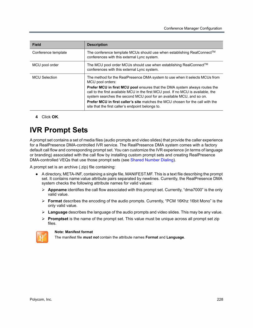
Conference Manager Configuration
Polycom, Inc. 228
4 Click OK.
IVR Prompt SetsA prompt set contains a set of media files (audio prompts and video slides) that provide the caller experience for a RealPresence DMA-controlled IVR service. The RealPresence DMA system comes with a factory default call flow and corresponding prompt set. You can customize the IVR experience (in terms of language or branding) associated with the call flow by installing custom prompt sets and creating RealPresence DMA-controlled VEQs that use those prompt sets (see Shared Number Dialing).
A prompt set is an archive (.zip) file containing:
● A directory, META-INF, containing a single file, MANIFEST.MF. This is a text file describing the prompt set. It contains name:value attribute pairs separated by newlines. Currently, the RealPresence DMA system checks the following attribute names for valid values:
Appname identifies the call flow associated with this prompt set. Currently, “dma7000” is the only valid value.
Format describes the encoding of the audio prompts. Currently, “PCM 16Khz 16bit Mono” is the only valid value.
Language describes the language of the audio prompts and video slides. This may be any value.
Promptset is the name of the prompt set. This value must be unique across all prompt set zip files.
Conference template The conference template MCUs should use when establishing RealConnectTM conferences with this external Lync system.
MCU pool order The MCU pool order MCUs should use when establishing RealConnectTM conferences with this external Lync system.
MCU Selection The method for the RealPresence DMA system to use when it selects MCUs from MCU pool orders:
Prefer MCU in first MCU pool ensures that the DMA system always routes the call to the first available MCU in the first MCU pool. If no MCU is available, the system searches the second MCU pool for an available MCU, and so on.
Prefer MCU in first caller’s site matches the MCU chosen for the call with the site that the first caller’s endpoint belongs to.
Note: Manifest format
The manifest file must not contain the attribute names Format and Language.
Field Description
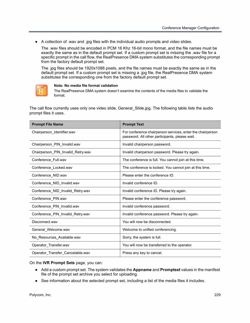
Conference Manager Configuration
Polycom, Inc. 229
● A collection of .wav and .jpg files with the individual audio prompts and video slides.
The .wav files should be encoded in PCM 16 Khz 16-bit mono format, and the file names must be exactly the same as in the default prompt set. If a custom prompt set is missing the .wav file for a specific prompt in the call flow, the RealPresence DMA system substitutes the corresponding prompt from the factory default prompt set.
The .jpg files should be 1920x1088 pixels, and the file names must be exactly the same as in the default prompt set. If a custom prompt set is missing a .jpg file, the RealPresence DMA system substitutes the corresponding one from the factory default prompt set.
The call flow currently uses only one video slide, General_Slide.jpg. The following table lists the audio prompt files it uses.
On the IVR Prompt Sets page, you can:
● Add a custom prompt set. The system validates the Appname and Promptset values in the manifest file of the prompt set archive you select for uploading.
● See information about the selected prompt set, including a list of the media files it includes.
Note: No media file format validation
The RealPresence DMA system doesn’t examine the contents of the media files to validate the format.
Prompt File Name Prompt Text
Chairperson_Identifier.wav For conference chairperson services, enter the chairperson password. All other participants, please wait.
Chairperson_PIN_Invalid.wav Invalid chairperson password.
Chairperson_PIN_Invalid_Retry.wav Invalid chairperson password. Please try again.
Conference_Full.wav The conference is full. You cannot join at this time.
Conference_Locked.wav The conference is locked. You cannot join at this time.
Conference_NID.wav Please enter the conference ID.
Conference_NID_Invalid.wav Invalid conference ID.
Conference_NID_Invalid_Retry.wav Invalid conference ID. Please try again.
Conference_PIN.wav Please enter the conference password.
Conference_PIN_Invalid.wav Invalid conference password.
Conference_PIN_Invalid_Retry.wav Invalid conference password. Please try again.
Disconnect.wav You will now be disconnected.
General_Welcome.wav Welcome to unified conferencing.
No_Resources_Available.wav Sorry, the system is full.
Operator_Transfer.wav You will now be transferred to the operator.
Operator_Transfer_Cancelable.wav Press any key to cancel.
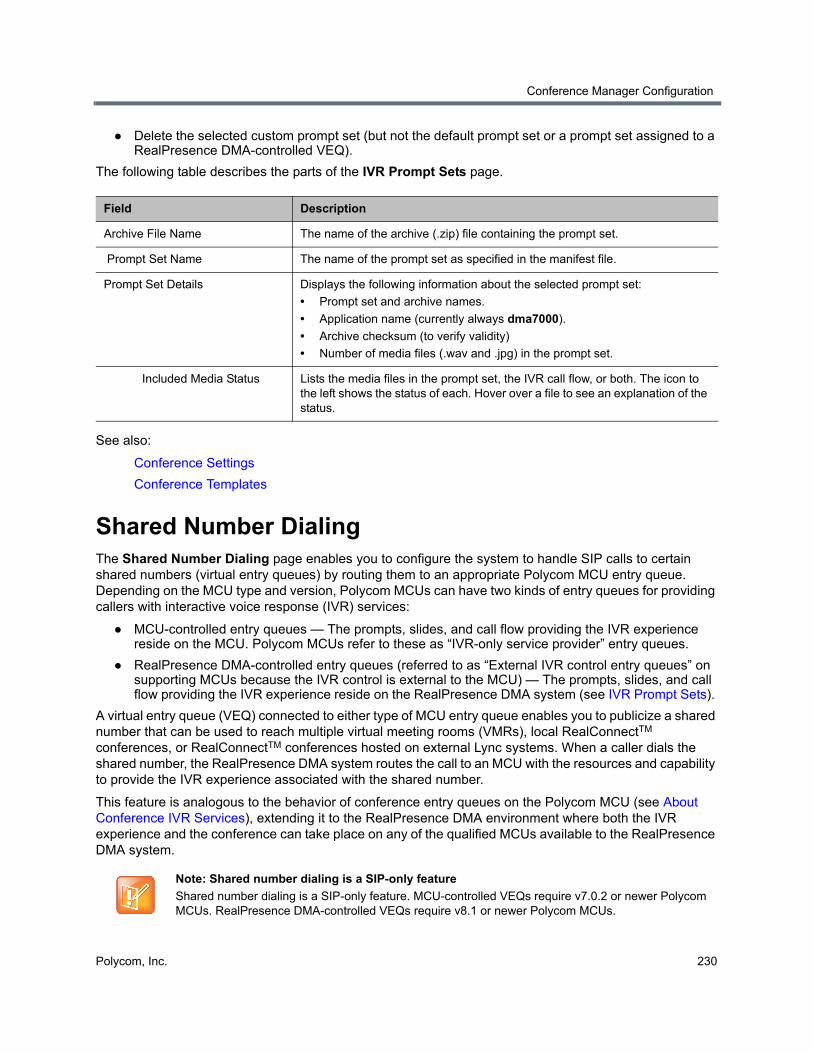
Conference Manager Configuration
Polycom, Inc. 230
● Delete the selected custom prompt set (but not the default prompt set or a prompt set assigned to a RealPresence DMA-controlled VEQ).
The following table describes the parts of the IVR Prompt Sets page.
See also:
Conference Settings
Conference Templates
Shared Number DialingThe Shared Number Dialing page enables you to configure the system to handle SIP calls to certain shared numbers (virtual entry queues) by routing them to an appropriate Polycom MCU entry queue. Depending on the MCU type and version, Polycom MCUs can have two kinds of entry queues for providing callers with interactive voice response (IVR) services:
● MCU-controlled entry queues — The prompts, slides, and call flow providing the IVR experience reside on the MCU. Polycom MCUs refer to these as “IVR-only service provider” entry queues.
● RealPresence DMA-controlled entry queues (referred to as “External IVR control entry queues” on supporting MCUs because the IVR control is external to the MCU) — The prompts, slides, and call flow providing the IVR experience reside on the RealPresence DMA system (see IVR Prompt Sets).
A virtual entry queue (VEQ) connected to either type of MCU entry queue enables you to publicize a shared number that can be used to reach multiple virtual meeting rooms (VMRs), local RealConnectTM conferences, or RealConnectTM conferences hosted on external Lync systems. When a caller dials the shared number, the RealPresence DMA system routes the call to an MCU with the resources and capability to provide the IVR experience associated with the shared number.
This feature is analogous to the behavior of conference entry queues on the Polycom MCU (see About Conference IVR Services), extending it to the RealPresence DMA environment where both the IVR experience and the conference can take place on any of the qualified MCUs available to the RealPresence DMA system.
Field Description
Archive File Name The name of the archive (.zip) file containing the prompt set.
Prompt Set Name The name of the prompt set as specified in the manifest file.
Prompt Set Details Displays the following information about the selected prompt set:
• Prompt set and archive names.
• Application name (currently always dma7000).
• Archive checksum (to verify validity)
• Number of media files (.wav and .jpg) in the prompt set.
Included Media Status Lists the media files in the prompt set, the IVR call flow, or both. The icon to the left shows the status of each. Hover over a file to see an explanation of the status.
Note: Shared number dialing is a SIP-only feature
Shared number dialing is a SIP-only feature. MCU-controlled VEQs require v7.0.2 or newer Polycom MCUs. RealPresence DMA-controlled VEQs require v8.1 or newer Polycom MCUs.
Conference Manager Configuration
Polycom, Inc. 231
The call flow works as follows:
1 Callers dial a shared number to reach the Polycom RealPresence DMA system.
2 The Polycom RealPresence DMA system recognizes the dialed number as a VEQ number and routes the call to a Polycom MCU configured to provide the IVR experience (MCU-controlled or RealPresence DMA-controlled) that’s associated with the VEQ number dialed.
3 If this is an MCU-controlled entry queue:
a The MCU uses its call flow, voice prompts, and video slides, prompting the caller for the conference ID of the destination conference and sending the response back to the Polycom RealPresence DMA system for validation.
b The Polycom RealPresence DMA system validates the conference ID entered by the caller.
If the number is invalid, the RealPresence DMA system instructs the MCU to re-prompt the caller. The number of retries is configurable.
c If the caller entered a valid conference ID, the RealPresence DMA system routes the call to the conference (selecting an appropriate MCU and starting the conference if necessary). Prompting for a passcode, if needed, is handled by the conference IVR service assigned to the conference template, if any, or the default conference IVR service.
4 If this is a RealPresence DMA-controlled entry queue:
a The Polycom RealPresence DMA system uses its call flow, voice prompts, and video slides, sending commands to the MCU to control the interaction with the caller (display slides, play prompts, collect tones, etc.).
b The Polycom RealPresence DMA system validates the conference ID entered by the caller.
If the caller entered an invalid number, the RealPresence DMA system instructs the MCU to re-prompt the caller. The number of retries is configurable. If the caller fails to enter a valid number or enters the (configurable) operator request command, the RealPresence DMA system routes the call to the operator (help desk) SIP URI.
c If the conference has a conference passcode (PIN), chairperson passcode, or both, the RealPresence DMA system instructs the MCU to prompt for and collect the passcode. The RealPresence DMA system validates the passcode entered by the caller.
If the caller entered an invalid passcode, the RealPresence DMA system instructs the MCU to re-prompt the caller. The number of retries is configurable. If the caller fails to enter a valid passcode or enters the (configurable) operator request command, the RealPresence DMA system routes the call to the operator (help desk) SIP URI.
d If the caller entered a valid passcode, the RealPresence DMA system routes the call to the conference (selecting an appropriate MCU and starting the conference if necessary), assigning the caller the appropriate role (chairperson or participant).
Note: Valid “Speed Dial” formats
For RealPresence DMA-controlled VEQ numbers, the RealPresence DMA system recognizes two “speed dial” SIP dial string formats:
• <veq number>**<conference ID> — The system validates the conference ID. If it’s valid, the caller bypasses the prompt for the destination conference. If the VMR has a conference passcode (PIN), chairperson passcode, or both, the system prompts for and validates the passcode.
• <veq number>**<conference ID>**<passcode> — The system validates the conference ID, and if it’s valid, the passcode. If both are valid, the caller bypasses both prompts and is placed directly into conference.
Conference Manager Configuration
Polycom, Inc. 232
The default dial plan contains a dial rule that routes calls whose dialed number is a VEQ dial-in number to the correct VEQ.
You can create up to 60 different VEQs to provide different IVR experiences (for instance, different language prompts or different greetings). You can designate one of the MCU-controlled VEQs as the Direct Dial VEQ, and the system will use it for calls dialed without a VEQ or conference ID. For instance, if a call’s dial string includes only the system’s domain name or IP address, the Polycom RealPresence DMA system uses the Direct Dial VEQ for it.
For MCU-controlled VEQs, to create a unique experience, you must create the corresponding entry queue on the Polycom MCUs to be used.
For RealPresence DMA-controlled VEQs, the MCU’s entry queue must be one of its “External IVR Entry Queues.” The prompt set for the VEQ must be installed on the RealPresence DMA system (see IVR Prompt Sets). Different “External IVR Entry Queues” can be created on the MCUs to provide different profiles (bit rate, resolution, etc.) for the pre-conference phase, but most of the entry queue experience (language, prompts, retries, and timers) is defined by the RealPresence DMA-controlled VEQ.
The Shared Number Dialing page lists the VEQs available on the system and enables you to add, edit and delete VEQs. The following table describes the fields on the page.
Note: Configuring MCUs for shared number dialing
The entry queues created for shared number dialing VEQs must have the IVR only service provider setting selected. See your Polycom MCU documentation.
When selecting an MCU to handle IVR for a VEQ, the Polycom RealPresence DMA system chooses from among those that have the entry queue specified for that VEQ, without regard to MCU pool orders.
As with conference profiles, it’s up to you to ensure that the entry queue is available on the MCUs to be used and that it’s the same on each MCU.
Field Description
Virtual Entry Queue The VEQ number, such as 12345, or Direct Dial.
Dial-In # The complete dial string, for this VEQ. For instance, if the system uses the prefix 71, this might be 7112345.
Description Typically, a description of the IVR experience, such as which language is used.
Response Entry Attempts The number of times a caller can enter an invalid VMR number before the system rejects the call.
Polycom MCU Entry Queue The name of the Polycom MCU entry queue (IVR experience) to be used for callers to this VEQ.
Entry Queue Type Type of entry queue.
IVR Prompt Set For a RealPresence DMA-controlled VEQ, the name of the IVR prompt set the VEQ uses (see IVR Prompt Sets).
Conference Manager Configuration
Polycom, Inc. 233
See also:
Add Direct Dial Virtual Entry Queue Dialog
Edit Virtual Entry Queue Dialog
Edit Direct Dial Virtual Entry Queue Dialog
Conference Templates
Conference Settings
IVR Prompt Sets
Add Virtual Entry Queue DialogLets you add a virtual entry queue (VEQ) to the list of configured VEQs on the Shared Number Dialing page. The following table describes the fields in the dialog.
Field Description
Virtual Entry Queue
Virtual entry queue number The VEQ number.
Dial-in number Number used to dial into the VEQ. Automatically set to the dialing prefix (see Conference Settings) plus VEQ number.
Description A meaningful description for this VEQ and its IVR experience, such as which language is used.
Response entry attempts The number of times a caller can enter an invalid VMR number before the system rejects the call.
Polycom MCU entry queue The Polycom MCU entry queue to use for this VEQ. The list includes all entry queues available on the Polycom MCUs connected to the system, with the number of MCUs that have each entry queue shown in parentheses.
Note: Polycom MCUs refer to entry queues designed for a RealPresence DMA-controlled VEQ as “External IVR” because RealPresence DMA-based IVR control is external to the MCU.
Unique external Lync system Instructs the system to attempt to resolve DTMF as a Lync conference ID for a specific external Lync system.
If this option is off, the system attempts to match the incoming DTMF against all defined external Lync systems.
If this option is on, the system attempts to match the incoming DTMF against the specific external Lync system you choose from the list. If a match is found, the appropriate dial rule is executed. If the selected unique external Lync system does not exist in the dial rule’s Selected external Lync systems box, the dial rule fails and the next dial rule is tried.
DMA-based IVR Call Flow (only for “External IVR control” entry queues)
IVR prompt set For a RealPresence DMA-controlled VEQ, the prompt set to be used. The list includes all those installed on the RealPresence DMA system (see IVR Prompt Sets).
Timeout for response entry (sec)
The length of time that the RealPresence DMA system waits for a caller to respond to a prompt (5-60 seconds).
Conference Manager Configuration
Polycom, Inc. 234
See also:
Shared Number Dialing
Add Direct Dial Virtual Entry Queue DialogLets you add a direct dial virtual entry queue (VEQ) to the list of configured VEQs on the Shared Number Dialing page. The following table describes the fields in the dialog.
DTMF terminator The terminator used to mark the end of caller input.
Operator assistance URI The SIP URI to which to route the call for operator (help desk) assistance.
Request operator transfer DTMF
The DTMF command for requesting an operator.
Note: If this digit string matches a VMR number, that VMR becomes unreachable.
Timeout to cancel operator request (sec)
The length of time after requesting an operator that a caller is given to cancel that request (1-10 seconds).
Note: An operator request can be canceled by entering any DTMF key.
Script Scripts entered in this section have access to the DTMF digits entered by callers. The system executes these scripts during VEQ processing, and can change and reject the DTMF digits callers enter. You can use this functionality to strip prefixes entered by a caller or to authorize participants dialing in to VEQs. These scripts are written in the Javascript language.
The Sample Virtual Entry Queue Script section provides an example VEQ script that you can modify for your own purposes.
Enabled Enable or disable the script in the Script text box.
Script Type (or paste) the VEQ script you want to apply. Then click Debug this Script to open the Script Debugging Dialog for VEQ Scripts and test the script with various variables.
Field Description
Description A meaningful description for this VEQ and its IVR experience, such as Direct Dial - English.
Response entry attempts The number of times a caller can enter an invalid VMR number before the system rejects the call.
Field Description
Conference Manager Configuration
Polycom, Inc. 235
See also:
Shared Number Dialing
Edit Virtual Entry Queue DialogLets you edit the virtual entry queue (VEQ) selected on the Shared Number Dialing page. The following table describes the fields in the dialog.
Polycom MCU entry queue The Polycom MCU entry queue to use for this VEQ. The list includes all entry queues available on the Polycom MCUs connected to the system, with the number of MCUs that have each entry queue shown in parentheses.
Unique external Lync system Instructs the system to attempt to resolve DTMF as a Lync conference ID for a specific external Lync system.
If this option is off, the system attempts to match the incoming DTMF against all defined external Lync systems.
If this option is on, the system attempts to match the incoming DTMF against the specific external Lync system you choose from the list. If a match is found, the appropriate dial rule is executed. If the selected unique external Lync system does not exist in the dial rule’s Selected external Lync systems box, the dial rule fails and the next dial rule is tried.
Field Description
Virtual Entry Queue
Virtual entry queue number The VEQ number.
Dial-in number Number used to dial into the VEQ. Automatically set to the dialing prefix (see Conference Settings) plus VEQ number.
Description A meaningful description for this VEQ and its IVR experience, such as which language is used.
Response entry attempts The number of times a caller can enter an invalid VMR number before the system rejects the call.
Field Description
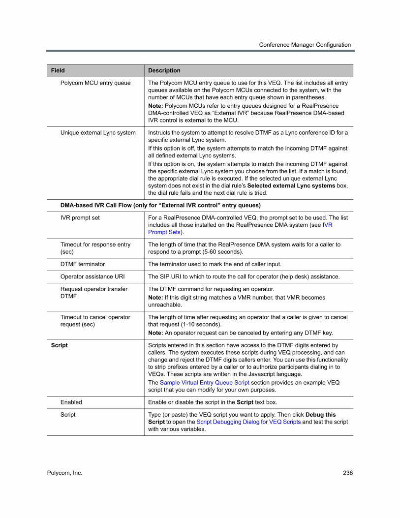
Conference Manager Configuration
Polycom, Inc. 236
Polycom MCU entry queue The Polycom MCU entry queue to use for this VEQ. The list includes all entry queues available on the Polycom MCUs connected to the system, with the number of MCUs that have each entry queue shown in parentheses.
Note: Polycom MCUs refer to entry queues designed for a RealPresence DMA-controlled VEQ as “External IVR” because RealPresence DMA-based IVR control is external to the MCU.
Unique external Lync system Instructs the system to attempt to resolve DTMF as a Lync conference ID for a specific external Lync system.
If this option is off, the system attempts to match the incoming DTMF against all defined external Lync systems.
If this option is on, the system attempts to match the incoming DTMF against the specific external Lync system you choose from the list. If a match is found, the appropriate dial rule is executed. If the selected unique external Lync system does not exist in the dial rule’s Selected external Lync systems box, the dial rule fails and the next dial rule is tried.
DMA-based IVR Call Flow (only for “External IVR control” entry queues)
IVR prompt set For a RealPresence DMA-controlled VEQ, the prompt set to be used. The list includes all those installed on the RealPresence DMA system (see IVR Prompt Sets).
Timeout for response entry (sec)
The length of time that the RealPresence DMA system waits for a caller to respond to a prompt (5-60 seconds).
DTMF terminator The terminator used to mark the end of caller input.
Operator assistance URI The SIP URI to which to route the call for operator (help desk) assistance.
Request operator transfer DTMF
The DTMF command for requesting an operator.
Note: If this digit string matches a VMR number, that VMR becomes unreachable.
Timeout to cancel operator request (sec)
The length of time after requesting an operator that a caller is given to cancel that request (1-10 seconds).
Note: An operator request can be canceled by entering any DTMF key.
Script Scripts entered in this section have access to the DTMF digits entered by callers. The system executes these scripts during VEQ processing, and can change and reject the DTMF digits callers enter. You can use this functionality to strip prefixes entered by a caller or to authorize participants dialing in to VEQs. These scripts are written in the Javascript language.
The Sample Virtual Entry Queue Script section provides an example VEQ script that you can modify for your own purposes.
Enabled Enable or disable the script in the Script text box.
Script Type (or paste) the VEQ script you want to apply. Then click Debug this Script to open the Script Debugging Dialog for VEQ Scripts and test the script with various variables.
Field Description
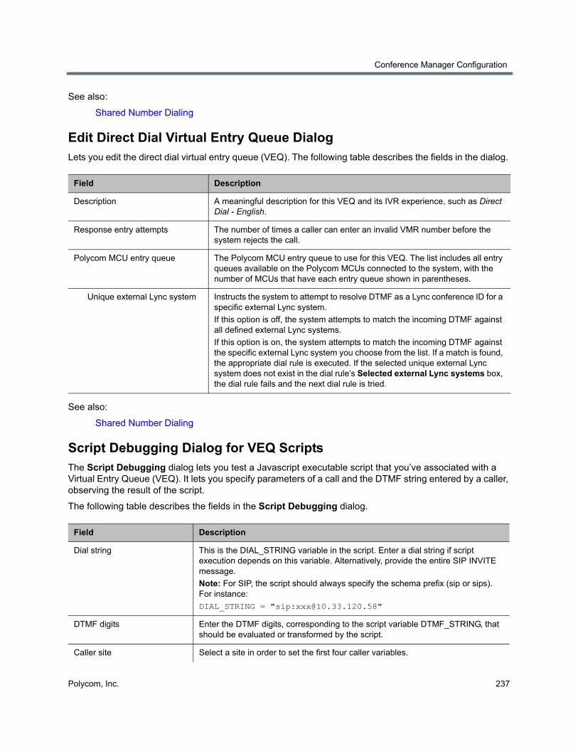
Conference Manager Configuration
Polycom, Inc. 237
See also:
Shared Number Dialing
Edit Direct Dial Virtual Entry Queue DialogLets you edit the direct dial virtual entry queue (VEQ). The following table describes the fields in the dialog.
See also:
Shared Number Dialing
Script Debugging Dialog for VEQ ScriptsThe Script Debugging dialog lets you test a Javascript executable script that you’ve associated with a Virtual Entry Queue (VEQ). It lets you specify parameters of a call and the DTMF string entered by a caller, observing the result of the script.
The following table describes the fields in the Script Debugging dialog.
Field Description
Description A meaningful description for this VEQ and its IVR experience, such as Direct Dial - English.
Response entry attempts The number of times a caller can enter an invalid VMR number before the system rejects the call.
Polycom MCU entry queue The Polycom MCU entry queue to use for this VEQ. The list includes all entry queues available on the Polycom MCUs connected to the system, with the number of MCUs that have each entry queue shown in parentheses.
Unique external Lync system Instructs the system to attempt to resolve DTMF as a Lync conference ID for a specific external Lync system.
If this option is off, the system attempts to match the incoming DTMF against all defined external Lync systems.
If this option is on, the system attempts to match the incoming DTMF against the specific external Lync system you choose from the list. If a match is found, the appropriate dial rule is executed. If the selected unique external Lync system does not exist in the dial rule’s Selected external Lync systems box, the dial rule fails and the next dial rule is tried.
Field Description
Dial string This is the DIAL_STRING variable in the script. Enter a dial string if script execution depends on this variable. Alternatively, provide the entire SIP INVITE message.
Note: For SIP, the script should always specify the schema prefix (sip or sips). For instance:
DIAL_STRING = "sip:[email protected]"
DTMF digits Enter the DTMF digits, corresponding to the script variable DTMF_STRING, that should be evaluated or transformed by the script.
Caller site Select a site in order to set the first four caller variables.
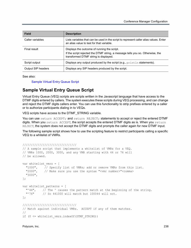
Conference Manager Configuration
Polycom, Inc. 238
See also:
Sample Virtual Entry Queue Script
Sample Virtual Entry Queue ScriptVirtual Entry Queue (VEQ) scripts are scripts written in the Javascript language that have access to the DTMF digits entered by callers. The system executes these scripts during VEQ processing, and can change and reject the DTMF digits callers enter. You can use this functionality to strip prefixes entered by a caller or to authorize participants dialing in to VEQs.
VEQ scripts have access to the DTMF_STRING variable.
You can use return ACCEPT; and return REJECT; statements to accept or reject the entered DTMF digits. When you return ACCEPT, the script accepts the entered DTMF digits as is. When you return REJECT, the system does not accept the DTMF digits and prompts the caller again for new DTMF input.
The following sample script shows how to use the scripting feature to restrict participants calling a specific VEQ to a whitelist of VMRs.
////////////////////////////////// A sample script that implements a whitelist of VMRs for a VEQ.// VMRs 1000, 2000, 3000, and any VMR starting with 44 or 76 will// be allowed.
var whitelist_vmrs = [ "1000", // Specify list of VMRs; add or remove VMRs from this list. "2000", // Make sure you use the syntax "<vmr number>"<comma> "3000", ]; var whitelist_patterns = [ "^44", // The ^ causes the pattern match at the beginning of the string. "^76" // So 441000 will match but 100044 will not.]; ////////////////////////////////// Match against individual VMRs. ACCEPT if any of them matches.//if (0 <= whitelist_vmrs.indexOf(DTMF_STRING))
Caller variables Lists variables that can be used in the script to represent caller alias values. Enter an alias value to test for that variable.
Final result Displays the outcome of running the script.
If the script rejected the DTMF string, a message tells you so. Otherwise, the transformed DTMF string is displayed.
Script output Displays any output produced by the script (e.g., println statements).
Output SIP headers Displays any SIP headers produced by the script.
Field Description
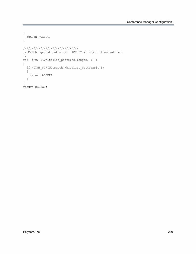
Conference Manager Configuration
Polycom, Inc. 239
{ return ACCEPT;} ////////////////////////////////// Match against patterns. ACCEPT if any of them matches.//for (i=0; i<whitelist_patterns.length; i++){ if (DTMF_STRING.match(whitelist_patterns[i])) { return ACCEPT; }}return REJECT;
Polycom, Inc. 240
Superclustering
This section describes the Polycom® RealPresence® Distributed Media Application™ (DMA®) 7000 system’s superclustering capability. It includes the following topics:
● About Superclustering
● DMAs
● Join Supercluster Dialog
● Supercluster Procedures
About SuperclusteringThe two-server configuration of the Polycom RealPresence DMA system is configured as a co-located two-server cluster, which enhances the reliability of the system by providing a measure of redundancy. To provide even greater reliability, geographic redundancy, and better network traffic management, multiple Polycom RealPresence DMA systems (either single-server or two-server systems) in distributed locations can be combined into a supercluster.
A supercluster is a set of up to five Polycom RealPresence DMA system clusters that are geographically dispersed, but still centrally managed. The clusters in a supercluster are all peers. There is no “master” or “primary” cluster. All have local copies of the same data store, which are kept consistent via replication.
This common data store enables all the Call Servers to share the same site topology, dial plan, bandwidth management, endpoint registrations, usage reporting, and status monitoring. Sharing and replicating this data also allows single-point management (configuration/re-configuration) of the shared data from any cluster of the supercluster. Up to three clusters can function as Conference Managers, hosting conference rooms and managing pools of MCUs.
Responsibility for most functionality, including Active Directory and Exchange integration, device registration, call handling, and conference room (VMR) hosting, is apportioned among the clusters using site topology territories. You can assign a set of responsibilities to each territory, and you can assign a primary cluster and a backup cluster for each territory. When the primary cluster is online, it controls the territory and carries out all of the responsibilities belonging to the territory. When the primary cluster is offline, the backup cluster assumes control of the territory and carries out all of the territory’s responsibilities.
A standalone (not superclustered) Polycom RealPresence DMA system has a single default territory for which it’s the primary cluster (and of course there is no backup). When you join other clusters to it to create a supercluster, it still has that same single default territory, it’s still the primary cluster for the default territory, and there is still no backup cluster. Essentially, one cluster is responsible for everything, and the others do nothing. So immediately after forming a new supercluster, you should do the following:
1 If you haven’t already done so, create your site topology data or integrate with a Polycom RealPresence Resource Manager system to obtain it. See Site Topology.
Superclustering
Polycom, Inc. 241
2 Determine how you want to organize your sites into territories in order to best distribute responsibilities and workload among the clusters of your supercluster. A number of strategies are possible. For instance, with a five-cluster supercluster, you could adopt one of the following schemes:
Create four territories, assign a primary cluster for each, and assign the fifth cluster as backup for all four.
Create five territories, assign a primary cluster for each, and make each cluster the backup for one of the other territories.
Use some hybrid of the above that best suits your enterprise network’s distribution of sites, users, and traffic.
Keep in mind that only three territories can host conference rooms.
3 Create the territories needed, assign functionality responsibilities to the territories, and assign primary and backup clusters to the territories.
See also:
Supercluster Procedures
DMAsThe DMAs page lets you create, view, and manage a supercluster of Polycom RealPresence DMA systems (see About Superclustering).
If the system you’re logged in to is not (and has not been) part of a supercluster, the list contains only that system. The Join Supercluster command lets you:
Note: RealPresence Resource Manager integration
If you’ve integrated with a Polycom RealPresence Resource Manager system, site topology data comes from that system and can’t be edited in the RealPresence DMA system. You must create the territories needed in the RealPresence Resource Manager system.
Note: Supercluster software versions must match
All the clusters in a supercluster must be running compatible software versions. Patch releases of the same major version will generally be compatible, but major version upgrades will not be compatible. Major version software upgrades of a supercluster take careful planning. See Incompatible Software Version Supercluster Upgrades.
If you’re planning to form a supercluster, we encourage you to upgrade to the latest version before doing so.
Note: Create required DNS records
The host names (virtual and physical) of every cluster in the supercluster must be resolvable by all the other clusters. For a superclustered system, A/AAAA records on your DNS server(s) for each physical host name, physical IP address, and virtual host name are mandatory. See Add Required DNS Records for the Polycom RealPresence DMA System.
Superclustering is not supported in Maximum security mode. See The Consequences of Enabling Maximum Security Mode.
Superclustering
Polycom, Inc. 242
● Create a new supercluster by pointing it to another free-standing (not superclustered) Polycom RealPresence DMA system. Both systems become clusters in the new supercluster. The system you’re logged in to has its local data store largely replaced by a copy of the data store from the system to which you pointed it. The data from that other system becomes the shared supercluster data store.
● Add the system to an existing supercluster by pointing it to one of the existing clusters in the supercluster. The system you’re logged in to becomes one of the clusters in that supercluster, and its local data store is largely replaced by a copy of the shared supercluster data store.
If a supercluster exists, the Remove from Supercluster command lets you remove the cluster selected in the list from the supercluster, re-initializing it as a new stand-alone cluster. It retains the data and configuration from the supercluster (including site topology), but that data is no longer synchronized to the common data store. If the cluster you’re removing is responsible for any territories (as primary or backup), you must first reassign those territories. The cluster being removed may be either the one you’re logged in to or another cluster. The system prompts you to confirm.
The Busy Out command gracefully winds down the use of the selected cluster:
● Existing calls and conferences on the selected cluster continue, but no new conferences are allowed to start. New calls are allowed to start only if they are associated with existing conferences. Registrations are rejected, except for endpoints currently involved in calls. The cluster ceases to manage bandwidth.
● Territories for which the selected cluster has primary responsibility and a different cluster has backup responsibility are transferred to the backup cluster.
● Registrations are seamlessly transferred to the backup cluster (for endpoints that support this). Bandwidth usage data for ongoing calls is seamlessly transferred to the backup cluster.
The Stop Using command takes the selected cluster immediately out of service:
● Existing calls and conferences on the selected cluster are disconnected. No new calls or conferences are allowed to start. All registrations are rejected. The cluster ceases to manage bandwidth.
Caution: Adding a cluster to a supercluster overwrites data
When you add the cluster you’re logged in to to an existing supercluster, virtually all of that cluster’s data and configuration are replaced by the shared data and configuration of the supercluster. This includes, among other things, users, groups, conference rooms, site topology, Conference Manager configuration, Call Server configuration, and integrations.
When you create a new supercluster, the data and configuration of the cluster you’re logged in to are replaced by the data and configuration of the cluster to which you’re pointing it.
Be sure you create a new supercluster by joining the cluster you’re logged in to to the cluster that has the data and configuration you want to preserve. For instance, if one of the clusters is integrated with your Polycom RealPresence Resource Manager system, join the other cluster to it, not the other way around.
Note: Superclusters and RealPresence Resource Manager integration
You can’t add a Polycom RealPresence Resource Manager system to a supercluster or create a supercluster with a Polycom RealPresence Resource Manager system. But you can integrate a Polycom RealPresence DMA cluster with a Polycom RealPresence Resource Manager system in order to get site topology and user-to-device association data from the latter (see RealPresence Resource Manager Integration). You can do this either before or after creating a Polycom RealPresence DMA supercluster. The site topology and user-to-device association data is replicated throughout the supercluster.
Superclustering
Polycom, Inc. 243
● Territories for which the selected cluster has primary responsibility and a different cluster has backup responsibility are transferred to the backup cluster.
● Registrations are seamlessly transferred to the backup cluster (for endpoints that support this). Bandwidth usage data for ongoing calls is seamlessly transferred to the backup cluster.
The Start Using command puts the selected cluster back into service:
● New calls and conferences are allowed to start. The cluster begins bandwidth management.
● The cluster assumes control of any territories for which it has primary responsibility, or for which it has backup responsibility and the primary cluster is offline.
● For territories for which the restarted cluster is the primary, existing calls and conferences on the backup cluster continue, but no new conferences are allowed to start. New calls are allowed to start only if they are associated with existing conferences. The backup cluster ceases to manage bandwidth.
● Registrations are seamlessly transferred to the restarted primary cluster, where supported by the endpoint. Bandwidth usage data for ongoing calls is seamlessly transferred to the restarted primary cluster.
The following table describes the fields on the page.
Note: Shutting down a supercluster
There is no mechanism for shutting down an entire supercluster. If you want to shut down all clusters in a supercluster, you must do so one cluster at a time. See Shutting Down and Restarting and pay attention to the caution there.
Warning: Restart or reset supercluster services in an emergency only
Restart Supercluster Services and Reset Supercluster Services are emergency actions that should only be taken when instructed to do so by a Polycom Global Services representative. They’re intended only for resolving data store replication problems that can’t be resolved by other means.
Restart Supercluster Services restarts supercluster services on the selected cluster. All calls are terminated and the cluster becomes unresponsive for a short period of time.
Reset Supercluster Services hard-resets supercluster services on the selected cluster and resets the cluster to its initial defaults. This results in the loss of data. All calls are terminated, and the cluster is forced to leave the supercluster and rebooted.
Column Description
Host Name Virtual host name of the cluster’s signaling interface.
IP Address Virtual IP address of the clusters signaling interface.
Model Type of system. Currently, only RealPresence DMA 7000 systems may join a supercluster.
Version Software version of the system.
RAS Port The UDP port the cluster uses for H.323 RAS (Registration, Admission and Status) signaling.
SIP TCP Port The TCP port number the cluster uses for SIP.
SIP UDP Port The UDP port number the cluster uses for SIP.
Superclustering
Polycom, Inc. 244
See also:
About Superclustering
Supercluster Procedures
Join Supercluster DialogIn the Supercluster page’s action list, the Join Supercluster command lets you add a Polycom RealPresence DMA system to an existing supercluster or create a new one. It opens the Join Supercluster dialog, where you can specify any cluster in the supercluster to join. If the cluster you specify isn’t already part of an existing supercluster, joining to it creates a new supercluster that gets its shared data store from the cluster you specify.
The following table describes the fields in the Join Supercluster dialog.
See also:
About Superclustering
DMAs
SIP TLS Port The TLS port number the cluster uses for SIP.
Status Indicates whether the cluster is superclustered and whether it’s in service.
Time The time and date that the status was checked.
Note: Supercluster software versions must match
All the clusters in a supercluster must be running compatible software versions. Patch releases of the same major version will generally be compatible, but major version upgrades will not be compatible. If the software version of the system you’re adding isn’t compatible with the supercluster or cluster to which you’re joining it, a message tells you so and the join operation is terminated.
The host names (virtual and physical) of every cluster in the supercluster must be resolvable by all the other clusters. For a superclustered system, A/AAAA records on your DNS server(s) for each physical host name, physical IP address, and virtual host name are mandatory. See Add Required DNS Records for the Polycom RealPresence DMA System.
Column Description
Host name or IP address Any existing cluster in the supercluster to which the Polycom RealPresence DMA system should be joined, or the system with which to form a new supercluster. We strongly recommend specifying the FQDN of the virtual management interface for the cluster to be joined.
User name An administrator login name for the specified cluster.
Password The password for the administrator login.
Column Description
Superclustering
Polycom, Inc. 245
Supercluster Procedures
To create or join a supercluster
1 Go to Network > RealPresence DMAs.
2 In the Actions list, click Join Supercluster.
3 In the Join Supercluster dialog, do one of the following:
To create a new supercluster, enter the FQDN or host name of the virtual management interface for the other Polycom RealPresence DMA cluster with which to form the supercluster. Be sure the other cluster is the one whose data store you want shared with the supercluster.
To add this system to an existing supercluster, enter the FQDN or host name of the virtual management interface of one of the clusters in the supercluster.
4 Enter the user name and password with which to log into the Polycom RealPresence DMA cluster you specified.
5 Click OK.
A prompt warns you that the system will restart and local data will be overwritten, and asks you to confirm.
6 Click Yes.
The cluster you’re logged in to connects to the cluster you specified and establishes or joins the supercluster. It obtains supercluster-wide configuration and data (this may take a few minutes). A dialog informs you when the process is complete and the cluster is ready to restart. Shortly after that, the cluster logs you out and restarts.
7 Click OK to log out immediately, or simply wait.
Note: Verify DNS records
Prior to creating a supercluster, we recommend verifying that DNS can resolve all FQDNs of all clusters to become part of the supercluster. To do so, go to Maintenance > Troubleshooting Utilities > Ping and ping the FQDNs (virtual and physical) of the other cluster(s). Do this on each cluster.
Note: Allow supercluster join operations to complete
You can only add one cluster to a supercluster at a time. Wait until the current join operation is completely finished before attempting to add another cluster to the supercluster. The join operation may take several minutes, and the time required increases as the number of clusters in the supercluster increases.
Note: Create required DNS records
You may specify an IP address instead, but the host names (virtual and physical) of every cluster in the supercluster must be resolvable by all the other clusters. For a superclustered system, A/AAAA records on your DNS server(s) for each physical host name, physical IP address, and virtual host name are mandatory. See Add Required DNS Records for the Polycom RealPresence DMA System.
Note: Restart your browser
You may need to restart your browser or flush your browser cache in order to log back into the system.
Superclustering
Polycom, Inc. 246
8 Log back in and verify that the Supercluster Status pane of the Dashboard shows the correct number of servers and clusters, and there are no warnings.
9 Go to Network > RealPresence DMAs, verify that the status of each RealPresence DMA cluster is Superclustered, and reassign territory responsibilities as needed.
To remove a cluster from the supercluster
1 Make sure that there are no calls on the cluster, and that all of its MCUs are out of service. See Busy Out an MCU.
2 Reassign all of the cluster’s territory responsibilities to a different cluster.
3 Go to Network > RealPresence DMAs. In the list, select the cluster you want to remove.
4 In the Actions list, select Remove from Supercluster.
5 When asked to confirm that you want to remove the cluster, click Yes.
The selected cluster is removed from the supercluster. A dialog informs you when the process is complete. If the cluster you removed is the one you’re logged in to, it logs you out and restarts.
6 Click OK to log out immediately, or simply wait.
7 Log into the system you removed and verify on the Supercluster Status pane of the Dashboard that the system is no longer superclustered.
See also:
About Superclustering
DMAs
Join Supercluster Dialog
Note: Remove a cluster only while its servers are operational
If possible, remove a cluster only while its server or servers are on line. If you must remove a cluster while one or both servers are off line, be aware that an offline server may be in an inconsistent state when it’s brought back on line. If this occurs, the system attempts to auto-correct the situation. But if the auto-correction steps fail, the only supported procedure for fixing a server in this state is to re-install it from media.
Note: Restart your browser
You may need to restart your browser or flush your browser cache in order to log back into the system.
Polycom, Inc. 247
Call Server Configuration
This section describes the Polycom® RealPresence® Distributed Media Application™ (DMA®) 7000 system’s configuration tools and tasks related to its Call Server:
● About the Call Server Capabilities
● Call Server Settings
● Domains
● Dial Rules
● Preliminary/Postliminary Scripting
● Hunt Groups
● Device Authentication
● Registration Policy
● Prefix Service
● Embedded DNS
● History Retention Settings
These are settings and features that are shared across superclustered systems. See Introduction to the Polycom RealPresence DMA System.
About the Call Server CapabilitiesThe Polycom RealPresence DMA system’s Call Server capabilities provide gatekeeper functionality (if H.323 signaling is enabled), SIP proxy server and registrar functionality (if SIP signaling is enabled), and bandwidth management.
The system can also function as an H.323 <-> SIP gateway.
Note: Call server characteristics
In H.323, DTMF tones are usually sent over the H.323 signaling path. In SIP, DTMF tones are usually sent over the media path as a special RTP payload packet (see RFC 4733). Because of this difference and because the RealPresence DMA system isn’t in the media path, its gateway function doesn’t support DTMF transmission.
The gateway function also doesn’t support content sharing or AES encryption.
The RealPresence DMA system’s gateway function is used only for calls to registered endpoints, SIP peers, and H.323 gatekeepers. It’s not used for calls to virtual meeting rooms (VMRs), virtual entry queues (VEQs), external addresses, or IP addresses.
See The RealPresence DMA System as a SIP <–> H.323 Gateway for more information.
Call Server Configuration
Polycom, Inc. 248
In addition, the system can be integrated with a Juniper Networks Service Resource Controller (SRC) to provide bandwidth assurance services.
Call server configuration begins with enabling the desired signaling on each cluster’s Signaling Settings page. Other Call Server settings are shared across all systems in a supercluster and set on the Admin > Call Server pages.
See also:
Call Server Configuration
Call Server Settings
Call Server SettingsOn the Call Server Settings page, you can specify certain gatekeeper and SIP proxy settings used by the Polycom RealPresence DMA system Call Server. These settings are shared across the supercluster and apply to all the clusters.
The following table describes the fields on the page.
Note: IPV4 addresses preferred for signaling communication
In an IPv4 + IPv6 environment, the Polycom RealPresence DMA system gatekeeper prefers the IPv4 address for devices that register with both. For example, if endpoint A is a dual-stack device (that is, it supports both IPv4 and IPv6) and registers over IPv6 to a Polycom RealPresence DMA system that’s also dual-stack, the RRQ (Registration Request) message informs the RealPresence DMA gatekeeper of the endpoint's IPv6 and IPv4 addresses (as well as its E.164 alias, etc.).
If endpoint A dials the E.164 address of another dual-stack endpoint (endpoint B), the RealPresence DMA gatekeeper gives preference to the IPv4 address by sending endpoint B's IPv4 address in the ACF (Admission Confirm) message to endpoint A. Even though the initial ARQ and corresponding ACF were over IPv6, the expected behavior is that endpoint A will continue the H.323 signaling session to endpoint B over IPv4 since the RealPresence DMA gatekeeper informed endpoint A of endpoint B's IPv4 signaling IP.
Field Description
General Settings
Allow calls to/from rogue endpoints
If this option is selected, the Call Server permits rogue endpoints to place and receive calls. Rogue endpoints are endpoints that are in sites managed by the system, but are not registered and active.
Turning this option off blocks calls from and to rogue endpoints.
This option has no effect on other unregistered network devices (such as MCUs, GKs, and SBCs) or on endpoints that are not in sites managed by the system.
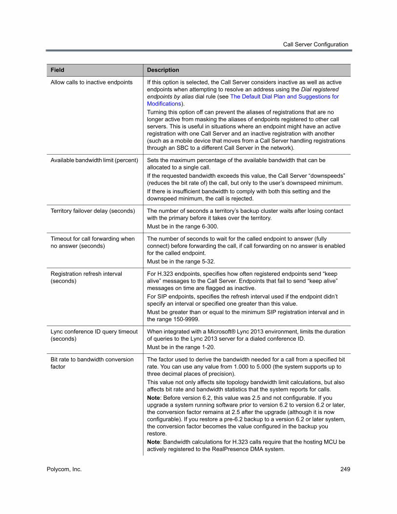
Call Server Configuration
Polycom, Inc. 249
Allow calls to inactive endpoints If this option is selected, the Call Server considers inactive as well as active endpoints when attempting to resolve an address using the Dial registered endpoints by alias dial rule (see The Default Dial Plan and Suggestions for Modifications).
Turning this option off can prevent the aliases of registrations that are no longer active from masking the aliases of endpoints registered to other call servers. This is useful in situations where an endpoint might have an active registration with one Call Server and an inactive registration with another (such as a mobile device that moves from a Call Server handling registrations through an SBC to a different Call Server in the network).
Available bandwidth limit (percent) Sets the maximum percentage of the available bandwidth that can be allocated to a single call.
If the requested bandwidth exceeds this value, the Call Server “downspeeds” (reduces the bit rate of) the call, but only to the user’s downspeed minimum.
If there is insufficient bandwidth to comply with both this setting and the downspeed minimum, the call is rejected.
Territory failover delay (seconds) The number of seconds a territory’s backup cluster waits after losing contact with the primary before it takes over the territory.
Must be in the range 6-300.
Timeout for call forwarding when no answer (seconds)
The number of seconds to wait for the called endpoint to answer (fully connect) before forwarding the call, if call forwarding on no answer is enabled for the called endpoint.
Must be in the range 5-32.
Registration refresh interval (seconds)
For H.323 endpoints, specifies how often registered endpoints send “keep alive” messages to the Call Server. Endpoints that fail to send “keep alive” messages on time are flagged as inactive.
For SIP endpoints, specifies the refresh interval used if the endpoint didn’t specify an interval or specified one greater than this value.
Must be greater than or equal to the minimum SIP registration interval and in the range 150-9999.
Lync conference ID query timeout (seconds)
When integrated with a Microsoft® Lync 2013 environment, limits the duration of queries to the Lync 2013 server for a dialed conference ID.
Must be in the range 1-20.
Bit rate to bandwidth conversion factor
The factor used to derive the bandwidth needed for a call from a specified bit rate. You can use any value from 1.000 to 5.000 (the system supports up to three decimal places of precision).
This value not only affects site topology bandwidth limit calculations, but also affects bit rate and bandwidth statistics that the system reports for calls.
Note: Before version 6.2, this value was 2.5 and not configurable. If you upgrade a system running software prior to version 6.2 to version 6.2 or later, the conversion factor remains at 2.5 after the upgrade (although it is now configurable). If you restore a pre-6.2 backup to a version 6.2 or later system, the conversion factor becomes the value configured in the backup you restore.
Note: Bandwidth calculations for H.323 calls require that the hosting MCU be actively registered to the RealPresence DMA system.
Field Description
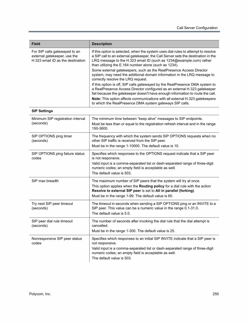
Call Server Configuration
Polycom, Inc. 250
For SIP calls gatewayed to an external gatekeeper, use the H.323 email ID as the destination
If this option is selected, when the system uses dial rules to attempt to resolve a SIP call to an external gatekeeper, the Call Server sets the destination in the LRQ message to the H.323 email ID (such as [email protected]) rather than utilizing the E.164 number alone (such as 1234).
Some external gatekeepers, such as the RealPresence Access Director system, may need the additional domain information in the LRQ message to correctly resolve the LRQ request.
If this option is off, SIP calls gatewayed by the RealPresence DMA system to a RealPresence Access Director configured as an external H.323 gatekeeper fail because the gatekeeper doesn't have enough information to route the call.
Note: This option affects communications with all external H.323 gatekeepers to which the RealPresence DMA system gateways SIP calls.
SIP Settings
Minimum SIP registration interval (seconds)
The minimum time between “keep alive” messages to SIP endpoints.
Must be less than or equal to the registration refresh interval and in the range 150-3600.
SIP OPTIONS ping timer (seconds)
The frequency with which the system sends SIP OPTIONS requests when no other SIP traffic is received from the SIP peer.
Must be in the range 1-10000. The default value is 10.
SIP OPTIONS ping failure status codes
Specifies which responses to the OPTIONS request indicate that a SIP peer is not responsive.
Valid input is a comma-separated list or dash-separated range of three-digit numeric codes; an empty field is acceptable as well.
The default value is 503.
SIP max breadth The maximum number of SIP peers that the system will try at once.
This option applies when the Routing policy for a dial rule with the action Resolve to external SIP peer is set to All in parallel (forking).
Must be in the range 1-99. The default value is 60.
Try next SIP peer timeout (seconds)
The timeout in seconds when sending a SIP OPTIONS ping or an INVITE to a SIP peer. This value can be a numeric value in the range 0.1-31.0.
The default value is 5.0.
SIP peer dial rule timeout (seconds)
The number of seconds after invoking the dial rule that the dial attempt is cancelled.
Must be in the range 1-300. The default value is 25.
Nonresponsive SIP peer status codes
Specifies which responses to an initial SIP INVITE indicate that a SIP peer is not responsive.
Valid input is a comma-separated list or dash-separated range of three-digit numeric codes; an empty field is acceptable as well.
The default value is 503.
Field Description
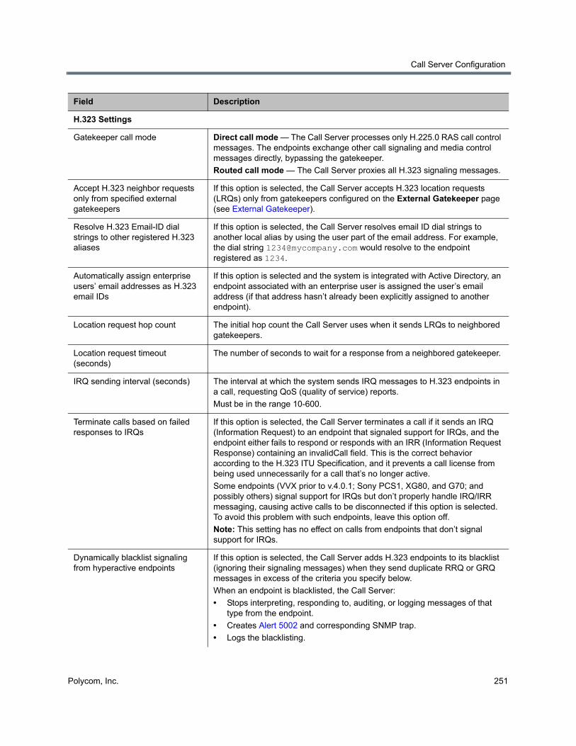
Call Server Configuration
Polycom, Inc. 251
H.323 Settings
Gatekeeper call mode Direct call mode — The Call Server processes only H.225.0 RAS call control messages. The endpoints exchange other call signaling and media control messages directly, bypassing the gatekeeper.
Routed call mode — The Call Server proxies all H.323 signaling messages.
Accept H.323 neighbor requests only from specified external gatekeepers
If this option is selected, the Call Server accepts H.323 location requests (LRQs) only from gatekeepers configured on the External Gatekeeper page (see External Gatekeeper).
Resolve H.323 Email-ID dial strings to other registered H.323 aliases
If this option is selected, the Call Server resolves email ID dial strings to another local alias by using the user part of the email address. For example, the dial string [email protected] would resolve to the endpoint registered as 1234.
Automatically assign enterprise users’ email addresses as H.323 email IDs
If this option is selected and the system is integrated with Active Directory, an endpoint associated with an enterprise user is assigned the user’s email address (if that address hasn’t already been explicitly assigned to another endpoint).
Location request hop count The initial hop count the Call Server uses when it sends LRQs to neighbored gatekeepers.
Location request timeout (seconds)
The number of seconds to wait for a response from a neighbored gatekeeper.
IRQ sending interval (seconds) The interval at which the system sends IRQ messages to H.323 endpoints in a call, requesting QoS (quality of service) reports.
Must be in the range 10-600.
Terminate calls based on failed responses to IRQs
If this option is selected, the Call Server terminates a call if it sends an IRQ (Information Request) to an endpoint that signaled support for IRQs, and the endpoint either fails to respond or responds with an IRR (Information Request Response) containing an invalidCall field. This is the correct behavior according to the H.323 ITU Specification, and it prevents a call license from being used unnecessarily for a call that’s no longer active.
Some endpoints (VVX prior to v.4.0.1; Sony PCS1, XG80, and G70; and possibly others) signal support for IRQs but don’t properly handle IRQ/IRR messaging, causing active calls to be disconnected if this option is selected. To avoid this problem with such endpoints, leave this option off.
Note: This setting has no effect on calls from endpoints that don’t signal support for IRQs.
Dynamically blacklist signaling from hyperactive endpoints
If this option is selected, the Call Server adds H.323 endpoints to its blacklist (ignoring their signaling messages) when they send duplicate RRQ or GRQ messages in excess of the criteria you specify below.
When an endpoint is blacklisted, the Call Server:
• Stops interpreting, responding to, auditing, or logging messages of that type from the endpoint.
• Creates Alert 5002 and corresponding SNMP trap.
• Logs the blacklisting.
Field Description
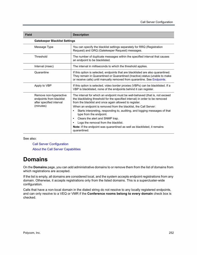
Call Server Configuration
Polycom, Inc. 252
See also:
Call Server Configuration
About the Call Server Capabilities
DomainsOn the Domains page, you can add administrative domains to or remove them from the list of domains from which registrations are accepted.
If the list is empty, all domains are considered local, and the system accepts endpoint registrations from any domain. Otherwise, it accepts registrations only from the listed domains. This is a supercluster-wide configuration.
Calls that have a non-local domain in the dialed string do not resolve to any locally registered endpoints, and can only resolve to a VEQ or VMR if the Conference rooms belong to every domain check box is checked.
Gatekeeper Blacklist Settings
Message Type You can specify the blacklist settings separately for RRQ (Registration Request) and GRQ (Gatekeeper Request) messages.
Threshold The number of duplicate messages within the specified interval that causes an endpoint to be blacklisted.
Interval (msec) The interval in milliseconds to which the threshold applies.
Quarantine If this option is selected, endpoints that are blacklisted are also quarantined. They remain in Quarantined or Quarantined (Inactive) status (unable to make or receive calls) until manually removed from quarantine. See Endpoints.
Apply to VBP If this option is selected, video border proxies (VBPs) can be blacklisted. If a VBP is blacklisted, none of the endpoints behind it can register.
Remove non-hyperactive endpoints from blacklist after specified interval (minutes)
The interval for which an endpoint must be well-behaved (that is, not exceed the blacklisting threshold for the specified interval) in order to be removed from the blacklist and once again allowed to register.
When an endpoint is removed from the blacklist, the Call Server:
• Starts interpreting, responding to, auditing, and logging messages of that type from the endpoint.
• Clears the alert and SNMP trap.
• Logs the removal from the blacklist.
Note: If the endpoint was quarantined as well as blacklisted, it remains quarantined.
Field Description
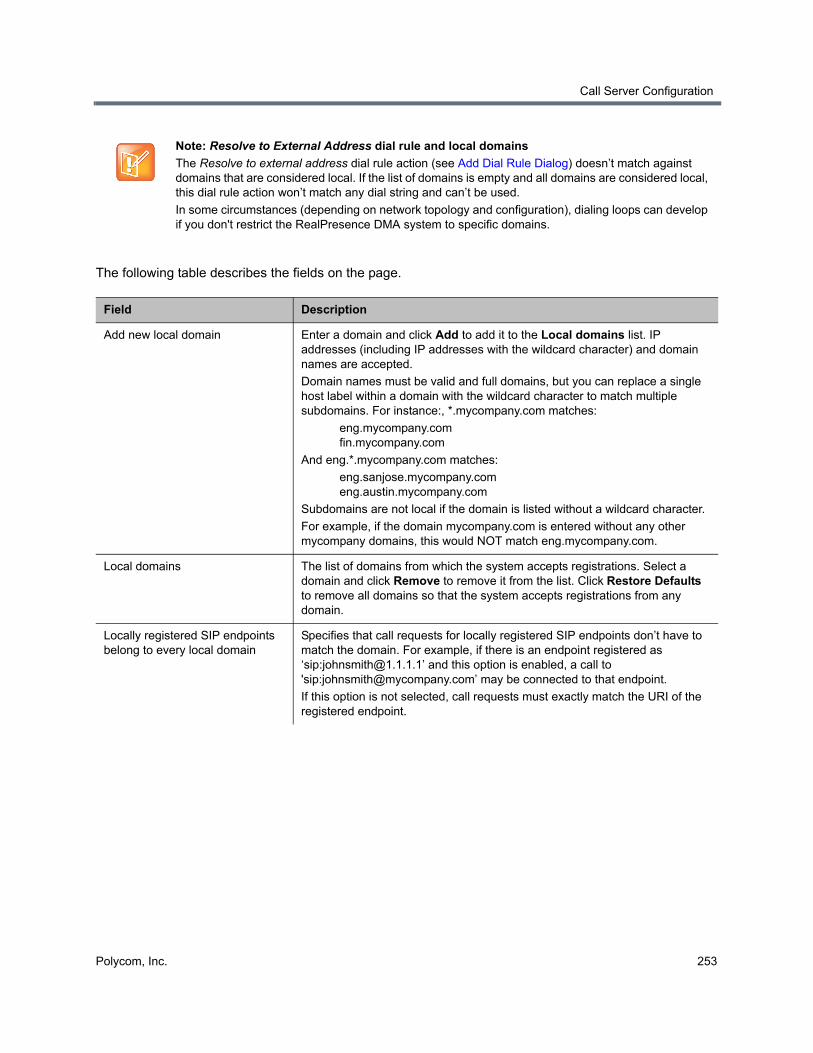
Call Server Configuration
Polycom, Inc. 253
The following table describes the fields on the page.
Note: Resolve to External Address dial rule and local domains
The Resolve to external address dial rule action (see Add Dial Rule Dialog) doesn’t match against domains that are considered local. If the list of domains is empty and all domains are considered local, this dial rule action won’t match any dial string and can’t be used.
In some circumstances (depending on network topology and configuration), dialing loops can develop if you don't restrict the RealPresence DMA system to specific domains.
Field Description
Add new local domain Enter a domain and click Add to add it to the Local domains list. IP addresses (including IP addresses with the wildcard character) and domain names are accepted.
Domain names must be valid and full domains, but you can replace a single host label within a domain with the wildcard character to match multiple subdomains. For instance:, *.mycompany.com matches:
eng.mycompany.com fin.mycompany.com
And eng.*.mycompany.com matches:
eng.sanjose.mycompany.com eng.austin.mycompany.com
Subdomains are not local if the domain is listed without a wildcard character.
For example, if the domain mycompany.com is entered without any other mycompany domains, this would NOT match eng.mycompany.com.
Local domains The list of domains from which the system accepts registrations. Select a domain and click Remove to remove it from the list. Click Restore Defaults to remove all domains so that the system accepts registrations from any domain.
Locally registered SIP endpoints belong to every local domain
Specifies that call requests for locally registered SIP endpoints don’t have to match the domain. For example, if there is an endpoint registered as ‘sip:[email protected]’ and this option is enabled, a call to 'sip:[email protected]’ may be connected to that endpoint.
If this option is not selected, call requests must exactly match the URI of the registered endpoint.

Call Server Configuration
Polycom, Inc. 254
See also:
Call Server Configuration
About the Call Server Capabilities
Dial RulesDial rules specify how the Polycom RealPresence DMA system Call Server uses the dial string to determine where to route the call. This dial string may include an IP address, a string of numbers that begin with a prefix associated with a service, a string that begins with a country code and city code, or a string that matches a particular alias for a device.
Dial strings may match multiple dial rules, but the rules have a priority order. When the Polycom RealPresence DMA system Call Server receives a call request and associated dial string, it applies the first matched (highest priority) dial rule.
The Call Server comes with a default dial plan installed that provides the most commonly needed address resolution processing. On the Dial Rules page, you can add, edit, remove, and change the order of the dial rules that make up the system’s dial plan. This is a supercluster-wide configuration.
The Call Server can optionally have a separate dial plan used only for untrusted (“unauthorized” or “guest”) SIP calls. These are calls from devices not registered with the RealPresence DMA system and outside the corporate firewall (but not part of a federated enterprise). These calls typically come to the RealPresence DMA system via session border controllers (SBCs) such as a Polycom RealPresence Access Director or Acme Packet Session Border Controller device.
You can configure the system to recognize and accept such calls on the Signaling Settings page (see H.323, SIP, and WebRTC Signaling). On the Dial Rules page, you can create a separate set of “guest” dial rules used only for these untrusted calls.
A dial rule consists of an optional preliminary script to modify dial strings and the action to be performed, which you select from a well-defined list of actions. These actions encapsulate potentially complex dial resolution logic, which shields you from having to deal with these complexities.
For instance, the Resolve to registered endpoint action applies all the associated system configurations and performs various searches on the internal endpoint registration records to determine if the inbound call
Email IDs of registered H.323 endpoints belong to every local domain
Specifies that call requests for locally registered H.323 endpoints’ email IDs don’t have to match the domain. For example, if there is an endpoint registered as ‘h323:[email protected]’ and this option is enabled, a call to 'h323:[email protected]’ may be connected to that endpoint.
If this option is not selected, call requests must exactly match the URI of the registered endpoint.
Conference rooms and virtual entry queues belong to every domain
Specifies that if the dial string specifies a conference room (VMR) or virtual entry queue (VEQ) on the Polycom RealPresence DMA system and includes a domain, a dial rule implementing the Resolve to conference room ID or Resolve to virtual entry queue actions (such as dial rule #2 or #3 of the default dial plan) ignores the domain and routes the call to that conference room or VEQ.
If this option is not selected, a dial string’s domain must be a local domain for the system to route the call to a conference room or VEQ.
Field Description
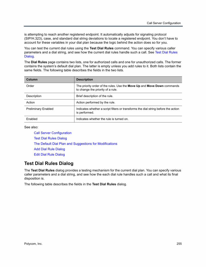
Call Server Configuration
Polycom, Inc. 255
is attempting to reach another registered endpoint. It automatically adjusts for signaling protocol (SIP/H.323), case, and standard dial string deviations to locate a registered endpoint. You don’t have to account for these variables in your dial plan because the logic behind the action does so for you.
You can test the current dial rules using the Test Dial Rules command. You can specify various caller parameters and a dial string, and see how the current dial rules handle such a call. See Test Dial Rules Dialog.
The Dial Rules page contains two lists, one for authorized calls and one for unauthorized calls. The former contains the system’s default dial plan. The latter is empty unless you add rules to it. Both lists contain the same fields. The following table describes the fields in the two lists.
See also:
Call Server Configuration
Test Dial Rules Dialog
The Default Dial Plan and Suggestions for Modifications
Add Dial Rule Dialog
Edit Dial Rule Dialog
Test Dial Rules DialogThe Test Dial Rules dialog provides a testing mechanism for the current dial plan. You can specify various caller parameters and a dial string, and see how the each dial rule handles such a call and what its final disposition is.
The following table describes the fields in the Test Dial Rules dialog.
Column Description
Order The priority order of the rules. Use the Move Up and Move Down commands to change the priority of a rule.
Description Brief description of the rule.
Action Action performed by the rule.
Preliminary Enabled Indicates whether a script filters or transforms the dial string before the action is performed.
Enabled Indicates whether the rule is turned on.
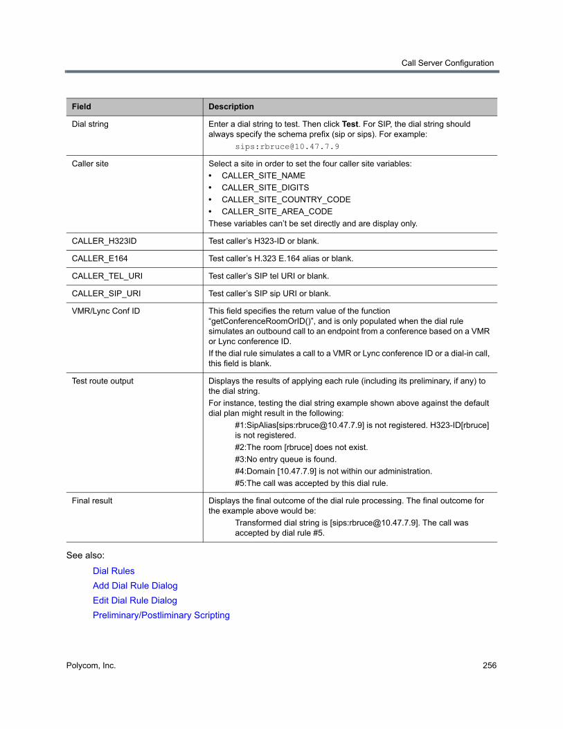
Call Server Configuration
Polycom, Inc. 256
See also:
Dial Rules
Add Dial Rule Dialog
Edit Dial Rule Dialog
Preliminary/Postliminary Scripting
Field Description
Dial string Enter a dial string to test. Then click Test. For SIP, the dial string should always specify the schema prefix (sip or sips). For example:
sips:[email protected]
Caller site Select a site in order to set the four caller site variables:
• CALLER_SITE_NAME
• CALLER_SITE_DIGITS
• CALLER_SITE_COUNTRY_CODE
• CALLER_SITE_AREA_CODE
These variables can’t be set directly and are display only.
CALLER_H323ID Test caller’s H323-ID or blank.
CALLER_E164 Test caller’s H.323 E.164 alias or blank.
CALLER_TEL_URI Test caller’s SIP tel URI or blank.
CALLER_SIP_URI Test caller’s SIP sip URI or blank.
VMR/Lync Conf ID This field specifies the return value of the function “getConferenceRoomOrID()”, and is only populated when the dial rule simulates an outbound call to an endpoint from a conference based on a VMR or Lync conference ID.
If the dial rule simulates a call to a VMR or Lync conference ID or a dial-in call, this field is blank.
Test route output Displays the results of applying each rule (including its preliminary, if any) to the dial string.
For instance, testing the dial string example shown above against the default dial plan might result in the following:
#1:SipAlias[sips:[email protected]] is not registered. H323-ID[rbruce] is not registered.
#2:The room [rbruce] does not exist.
#3:No entry queue is found.
#4:Domain [10.47.7.9] is not within our administration.
#5:The call was accepted by this dial rule.
Final result Displays the final outcome of the dial rule processing. The final outcome for the example above would be:
Transformed dial string is [sips:[email protected]]. The call was accepted by dial rule #5.
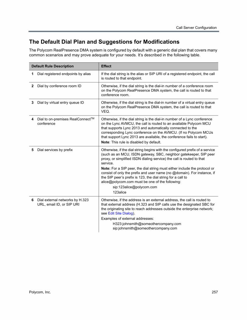
Call Server Configuration
Polycom, Inc. 257
The Default Dial Plan and Suggestions for ModificationsThe Polycom RealPresence DMA system is configured by default with a generic dial plan that covers many common scenarios and may prove adequate for your needs. It’s described in the following table.
Default Rule Description Effect
1 Dial registered endpoints by alias If the dial string is the alias or SIP URI of a registered endpoint, the call is routed to that endpoint.
2 Dial by conference room ID Otherwise, if the dial string is the dial-in number of a conference room on the Polycom RealPresence DMA system, the call is routed to that conference room.
3 Dial by virtual entry queue ID Otherwise, if the dial string is the dial-in number of a virtual entry queue on the Polycom RealPresence DMA system, the call is routed to that VEQ.
4 Dial to on-premises RealConnectTM conference
Otherwise, if the dial string is the dial-in number of a Lync conference on the Lync AVMCU, the call is routed to an available Polycom MCU that supports Lync 2013 and automatically connected to the corresponding Lync conference on the AVMCU. (If no Polycom MCUs that support Lync 2013 are available, the conference fails to start).
Note: This rule is disabled by default.
5 Dial services by prefix Otherwise, if the dial string begins with the configured prefix of a service (such as an MCU, ISDN gateway, SBC, neighbor gatekeeper, SIP peer proxy, or simplified ISDN dialing service) the call is routed to that service.
Note: For a SIP peer, the dial string must either include the protocol or consist of only the prefix and user name (no @domain). For instance, if the SIP peer’s prefix is 123, the dial string for a call to [email protected] must be one of the following:
123alice
6 Dial external networks by H.323 URL, email ID, or SIP URI
Otherwise, if the address is an external address, the call is routed to that external address (H.323 and SIP calls use the designated SBC for the originating site to reach addresses outside the enterprise network; see Edit Site Dialog).
Examples of external addresses:
H323:[email protected] sip:[email protected]
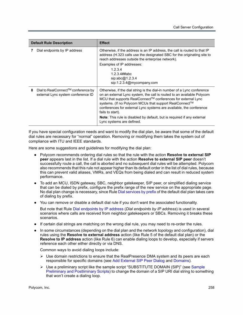
Call Server Configuration
Polycom, Inc. 258
If you have special configuration needs and want to modify the dial plan, be aware that some of the default dial rules are necessary for “normal” operation. Removing or modifying them takes the system out of compliance with ITU and IEEE standards.
Here are some suggestions and guidelines for modifying the dial plan:
● Polycom recommends ordering dial rules so that the rule with the action Resolve to external SIP peer appears last in the list. If a dial rule with the action Resolve to external SIP peer doesn’t successfully route a call, the call is aborted and no subsequent dial rules will be attempted. Polycom also recommends that this rule not appear higher than its default order in the list of dial rules, because this can prevent valid aliases, VMRs, and VEQs from being dialed and can result in reduced system performance.
● To add an MCU, ISDN gateway, SBC, neighbor gatekeeper, SIP peer, or simplified dialing service that can be dialed by prefix, configure the prefix range of the new service on the appropriate page. No dial plan change is necessary, since Rule Dial services by prefix of the default dial plan takes care of dialing by prefix.
● You can remove or disable a default dial rule if you don't want the associated functionality.
But note that Rule Dial endpoints by IP address (Dial endpoints by IP address) is used in several scenarios where calls are received from neighbor gatekeepers or SBCs. Removing it breaks these scenarios.
● If certain dial strings are matching on the wrong dial rule, you may need to re-order the rules.
● In some circumstances (depending on the dial plan and the network topology and configuration), dial rules using the Resolve to external address action (like Rule 5 of the default dial plan) or the Resolve to IP address action (like Rule 6) can enable dialing loops to develop, especially if servers reference each other either directly or via DNS.
Common ways to avoid dialing loops include:
Use domain restrictions to ensure that the RealPresence DMA system and its peers are each responsible for specific domains (see Add External SIP Peer Dialog and Domains).
Use a preliminary script like the sample script “SUBSTITUTE DOMAIN (SIP)” (see Sample Preliminary and Postliminary Scripts) to change the domain of a SIP URI dial string to something that won’t create a dialing loop.
7 Dial endpoints by IP address Otherwise, if the address is an IP address, the call is routed to that IP address (H.323 calls use the designated SBC for the originating site to reach addresses outside the enterprise network).
Examples of IP addresses:
1.2.3.4 1.2.3.4##abc sip:[email protected] sip:[email protected]
8 Dial to RealConnectTM conference by external Lync system conference ID
Otherwise, if the dial string is the dial-in number of a Lync conference on an external Lync system, the call is routed to an available Polycom MCU that supports RealConnectTM conferences for external Lync systems. (If no Polycom MCUs that support RealConnectTM conferences for external Lync systems are available, the conference fails to start).
Note: This rule is disabled by default, but is required if any external Lync systems are defined.
Default Rule Description Effect
Call Server Configuration
Polycom, Inc. 259
Use a postliminary script to similarly change the domain before sending to a peer.
Use configuration options on the peers to prevent loops.
Create a dial rule that uses the Block action and a preliminary script to enhance the system’s ability to prevent dialing loops for specific types of calls. The preliminary script ensures that the dial rule only matches the types of calls you want to block. This dial rule should be ordered after other dial rules that are expected to resolve the intended call requests.
For example, a dial rule with the Block action using the following preliminary script blocks all call requests that use a prefix of “44” if they have not been resolved by previous dial rules:
println("DIAL_STRING=" + DIAL_STRING);
var prefix='44'
var re = RegExp('^(sip:|sips:|h323:|tel:)?'+ prefix +'.*')
if(! DIAL_STRING.match(re))
{
println("NEXT_RULE");
return NEXT_RULE;
}
println("ACCEPT and terminate 44 prefix calls if they were not resolved by previous dial rules");
● You can add a filtering preliminary script to any dial rule to restrict the behavior of that rule.
For example, if you know that all the aliases of a specific neighbor gatekeeper are exactly ten digits long, you may want to route calls to that gatekeeper only if the dial string begins with a certain prefix followed by exactly ten digits.
To accomplish this, add a preliminary script to the service prefix dial rule that rejects all dial strings that begin with the prefix, but aren’t followed by exactly ten digits.
● To exclude certain dial strings, combine a filtering preliminary script with the Block action.
● You can use a preliminary script to modify the dial strings accepted by any of the rules.
For example, to be able to call an enterprise partner by dialing the prefix 7 followed by an alias in the partner’s namespace, configure a Resolve to external at transforms the string 7xxxx to H323:[email protected].
This type of dial string modification is also useful if you are using Lync conference dial strings with prefixes. To route a dial string with a prefix to a Lync conference ID, configure a Resolve to Lync conference ID action with a preliminary script that removes the prefix from the dial string (1234567 would become 4567, for example).
● If your enterprise includes another gatekeeper and you want to route calls to that gatekeeper without a prefix, add a dial rule using the Resolve to external gatekeeper action.
● If your enterprise includes a SIP peer and you want to route calls to that peer without a prefix, add a dial rule using the Resolve to external SIP peer action.
If you have multiple SIP peers, a call matching the rule is routed to the first one to answer. You may want to specify the domain(s) for which each is responsible (see Add External SIP Peer Dialog).
When routing to a SIP peer, the Polycom RealPresence DMA system gives up its ability to route the call to other locations if the peer rejects the call. Consequently, a dial rule using the Resolve to external SIP peer action should generally be the last rule in the dial plan.
Call Server Configuration
Polycom, Inc. 260
See also:
Dial Rules
Edit Dial Rule Dialog
Preliminary/Postliminary Scripting
Add Dial Rule DialogThe following table describes the fields in the Add Dial Rule dialog.
Note: SIP<->H.323 gateway considerations
In a mixed H.323 and SIP environment, the Polycom RealPresence DMA system acts as a seamless gateway. If an H.323 device sends it a Location Request (LRQ) and the dial plan contains a dial rule using the Resolve to external SIP peer action, the RealPresence DMA system will respond with a Location Confirm (LCF) because it can resolve the address by routing the H.323 call through its gateway to the SIP peer(s).
You can prevent H.323 calls from being routed to SIP peers by restricting which calls are routed to them in one or more of the following ways:
• Assign each SIP peer an authorized domain or domains (this is a good idea in any case in order to avoid dialing loops). See Edit External SIP Peer Dialog.
• Assign each SIP peer a prefix or prefix range. See Edit External SIP Peer Dialog.
• Add a preliminary script to the dial rule using the Resolve to external SIP peer action that ensures that the rule will only match a SIP address. See Preliminary/Postliminary Scripting.
Make the dial rule using the Resolve to external SIP peer action the last rule and ensure that all H.323 calls will match against one of the preceding dial rules.
See The RealPresence DMA System as a SIP <–> H.323 Gateway for more information.
Field Description
Dial Rule
Description The text description displayed on the Dial Rules page.
Action The action to be performed. When you select some actions, additional settings become available.
See the following table of dial rule actions for more information about the actions and the additional settings associated with them.
Enabled Clearing this check box lets you turn off a rule without deleting it.
Preliminary A preliminary is an executable script, written in the Javascript language, that defines processing actions (filtering or transformation) that are part of a dial rule and may be applied to a dial string before the dial rule’s action is performed.
Sample Preliminary and Postliminary Scripts provides some examples you can experiment with and modify for your purposes.
Enabled Lets you turn a preliminary on or off without deleting it.
Script Type (or paste) the preliminary script you want to apply. Then click Debug this Script to open the Script Debugging Dialog for Preliminaries/Postliminaries and test the script with various variables.
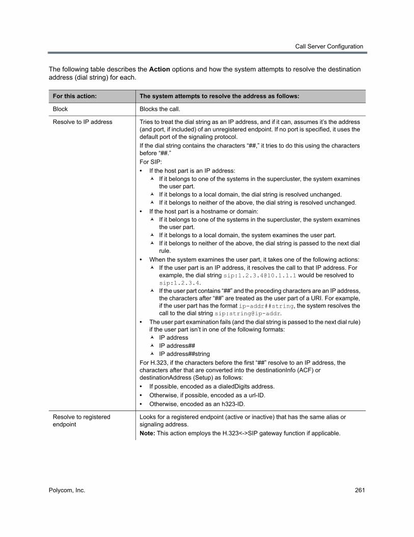
Call Server Configuration
Polycom, Inc. 261
The following table describes the Action options and how the system attempts to resolve the destination address (dial string) for each.
For this action: The system attempts to resolve the address as follows:
Block Blocks the call.
Resolve to IP address Tries to treat the dial string as an IP address, and if it can, assumes it’s the address (and port, if included) of an unregistered endpoint. If no port is specified, it uses the default port of the signaling protocol.
If the dial string contains the characters “##,” it tries to do this using the characters before “##.”
For SIP:
• If the host part is an IP address: If it belongs to one of the systems in the supercluster, the system examines
the user part. If it belongs to a local domain, the dial string is resolved unchanged. If it belongs to neither of the above, the dial string is resolved unchanged.
• If the host part is a hostname or domain: If it belongs to one of the systems in the supercluster, the system examines
the user part. If it belongs to a local domain, the system examines the user part. If it belongs to neither of the above, the dial string is passed to the next dial
rule.
• When the system examines the user part, it takes one of the following actions: If the user part is an IP address, it resolves the call to that IP address. For
example, the dial string sip:[email protected] would be resolved to sip:1.2.3.4.
If the user part contains “##” and the preceding characters are an IP address, the characters after “##” are treated as the user part of a URI. For example, if the user part has the format ip-addr##string, the system resolves the call to the dial string sip:string@ip-addr.
• The user part examination fails (and the dial string is passed to the next dial rule) if the user part isn’t in one of the following formats: IP address IP address## IP address##string
For H.323, if the characters before the first “##” resolve to an IP address, the characters after that are converted into the destinationInfo (ACF) or destinationAddress (Setup) as follows:
• If possible, encoded as a dialedDigits address.
• Otherwise, if possible, encoded as a url-ID.
• Otherwise, encoded as an h323-ID.
Resolve to registered endpoint
Looks for a registered endpoint (active or inactive) that has the same alias or signaling address.
Note: This action employs the H.323<->SIP gateway function if applicable.

Call Server Configuration
Polycom, Inc. 262
Resolve to Lync conference ID
Queries an integrated Lync SIP peer for a Lync AVMCU-based conference with a matching conference ID. This dial rule action enables Polycom RealConnectTM functionality for on-premises Lync systems only; it does not apply to external Lync systems. See Scheduled Conferences with Polycom RealConnect™.
When selected, the following fields are available:
• Conference template
When checked, you can select the conference template used to start the conference. If you leave this option unchanged, the Default conference template configured in Admin > Conference Manager > Conference Settings will be used. Keep in mind that the conference template must specify a Conference mode of AVC only, or the conference will not start. See Considerations and Requirements for Lync 2013 Integration.
• MCU pool order
Select the MCU pool order to use for MCUs that provide Lync AVMCU cascade functionality. If you leave this option unchecked, the dial rule will use the default pool order configured in the Default MCU pool order field on the Admin > Conference Manager > Conference Settings page.
• MCU Affinity Prefer MCU in first MCU pool
The RealPresence DMA system routes the call to the first available MCU in the first MCU pool. If no MCU is available, the system searches the second MCU pool for an available MCU, and so on.
Prefer MCU in first caller’s site
Matches the MCU chosen for the call with the site that the first caller’s endpoint belongs to.
• Available SIP peers / Selected SIP peers selection area
This area lists the names of Available SIP peers and any Selected SIP peers. With the provided arrow buttons, you can move SIP peers between the Available and Selected areas. When the dial rule is executed, the system will query the selected SIP peers to find which one is hosting the Lync conference.
Note: For an external SIP Peer to be listed in the Available SIP peers area, it must be listed on the Network > External SIP Peers page and have the following configuration: A Type of Microsoft The Enable RealConnectTM conferences check box selected in the Lync
Integration tab
Resolve to Lync Conference ID by Conference Auto Attendant
Examines the beginning of the dial string, searching for the longest matching prefix of a defined external Lync system. If a match is found, the dial rule removes the prefix from the dial string and passes the resulting conference ID to the Polycom MCU, which then contacts the CAA of the matched external Lync system.
If an external Lync system is listed on the Admin > Conference Manager > External Lync Systems page, it is available in the Available exernal Lync systems box. You can move external Lync systems to which the rule applies to the Selected external Lync systems box.
A dial rule with this action is required for Polycom MCUs to connect to Lync conferences on external Lync systems.
For this action: The system attempts to resolve the address as follows:
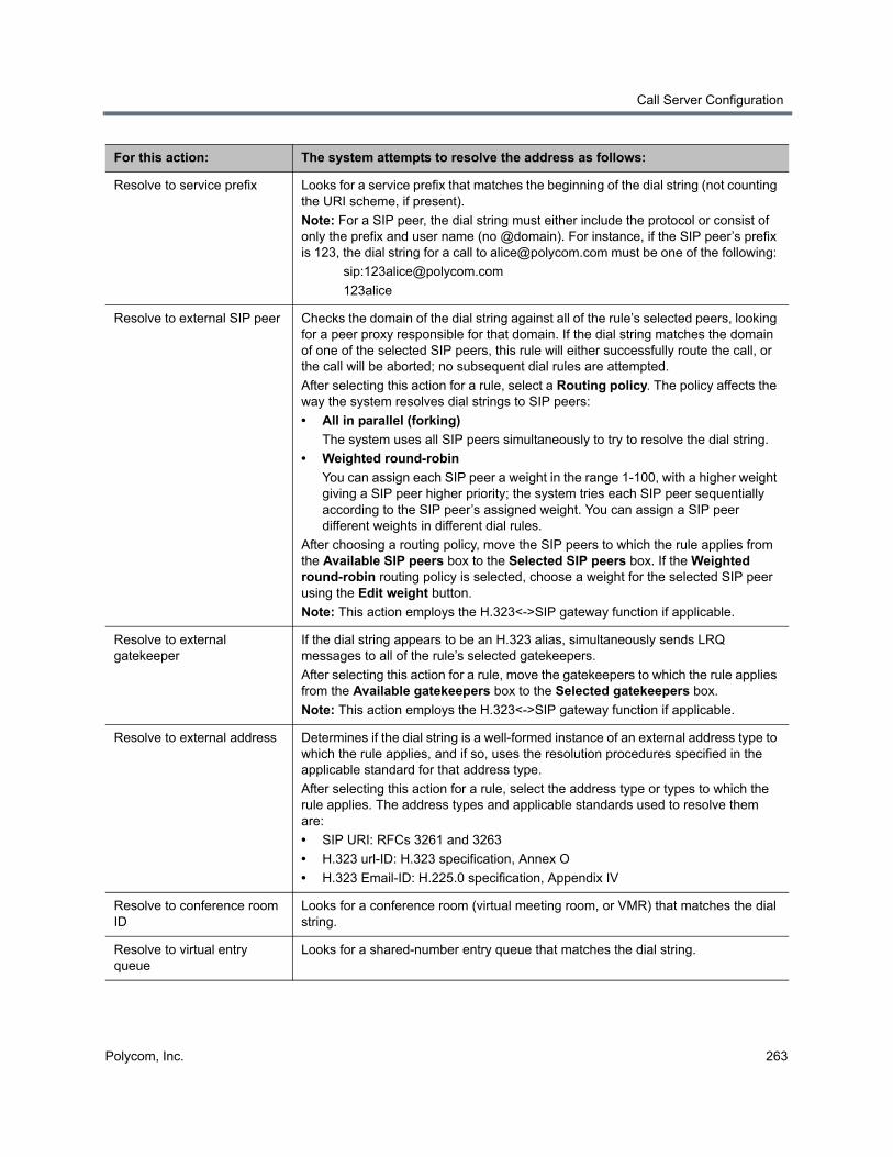
Call Server Configuration
Polycom, Inc. 263
Resolve to service prefix Looks for a service prefix that matches the beginning of the dial string (not counting the URI scheme, if present).
Note: For a SIP peer, the dial string must either include the protocol or consist of only the prefix and user name (no @domain). For instance, if the SIP peer’s prefix is 123, the dial string for a call to [email protected] must be one of the following:
123alice
Resolve to external SIP peer Checks the domain of the dial string against all of the rule’s selected peers, looking for a peer proxy responsible for that domain. If the dial string matches the domain of one of the selected SIP peers, this rule will either successfully route the call, or the call will be aborted; no subsequent dial rules are attempted.
After selecting this action for a rule, select a Routing policy. The policy affects the way the system resolves dial strings to SIP peers:
• All in parallel (forking)
The system uses all SIP peers simultaneously to try to resolve the dial string.
• Weighted round-robin
You can assign each SIP peer a weight in the range 1-100, with a higher weight giving a SIP peer higher priority; the system tries each SIP peer sequentially according to the SIP peer’s assigned weight. You can assign a SIP peer different weights in different dial rules.
After choosing a routing policy, move the SIP peers to which the rule applies from the Available SIP peers box to the Selected SIP peers box. If the Weighted round-robin routing policy is selected, choose a weight for the selected SIP peer using the Edit weight button.
Note: This action employs the H.323<->SIP gateway function if applicable.
Resolve to external gatekeeper
If the dial string appears to be an H.323 alias, simultaneously sends LRQ messages to all of the rule’s selected gatekeepers.
After selecting this action for a rule, move the gatekeepers to which the rule applies from the Available gatekeepers box to the Selected gatekeepers box.
Note: This action employs the H.323<->SIP gateway function if applicable.
Resolve to external address Determines if the dial string is a well-formed instance of an external address type to which the rule applies, and if so, uses the resolution procedures specified in the applicable standard for that address type.
After selecting this action for a rule, select the address type or types to which the rule applies. The address types and applicable standards used to resolve them are:
• SIP URI: RFCs 3261 and 3263
• H.323 url-ID: H.323 specification, Annex O
• H.323 Email-ID: H.225.0 specification, Appendix IV
Resolve to conference room ID
Looks for a conference room (virtual meeting room, or VMR) that matches the dial string.
Resolve to virtual entry queue
Looks for a shared-number entry queue that matches the dial string.
For this action: The system attempts to resolve the address as follows:

Call Server Configuration
Polycom, Inc. 264
See also:
Dial Rules
The Default Dial Plan and Suggestions for Modifications
Preliminary/Postliminary Scripting
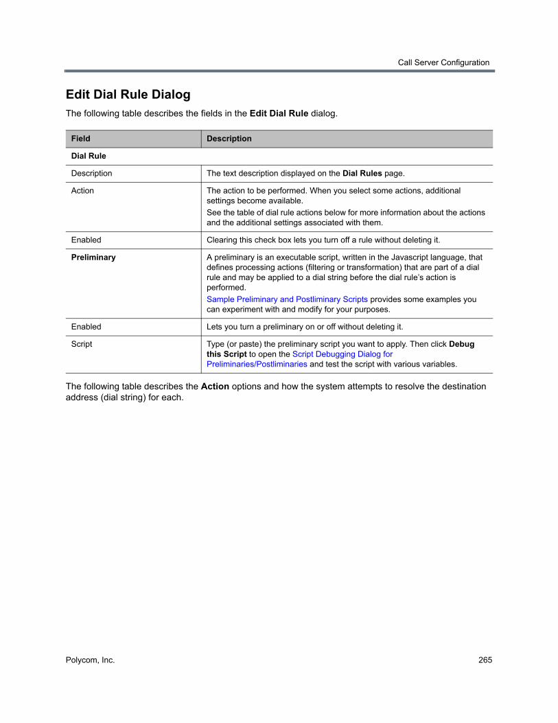
Call Server Configuration
Polycom, Inc. 265
Edit Dial Rule DialogThe following table describes the fields in the Edit Dial Rule dialog.
The following table describes the Action options and how the system attempts to resolve the destination address (dial string) for each.
Field Description
Dial Rule
Description The text description displayed on the Dial Rules page.
Action The action to be performed. When you select some actions, additional settings become available.
See the table of dial rule actions below for more information about the actions and the additional settings associated with them.
Enabled Clearing this check box lets you turn off a rule without deleting it.
Preliminary A preliminary is an executable script, written in the Javascript language, that defines processing actions (filtering or transformation) that are part of a dial rule and may be applied to a dial string before the dial rule’s action is performed.
Sample Preliminary and Postliminary Scripts provides some examples you can experiment with and modify for your purposes.
Enabled Lets you turn a preliminary on or off without deleting it.
Script Type (or paste) the preliminary script you want to apply. Then click Debug this Script to open the Script Debugging Dialog for Preliminaries/Postliminaries and test the script with various variables.
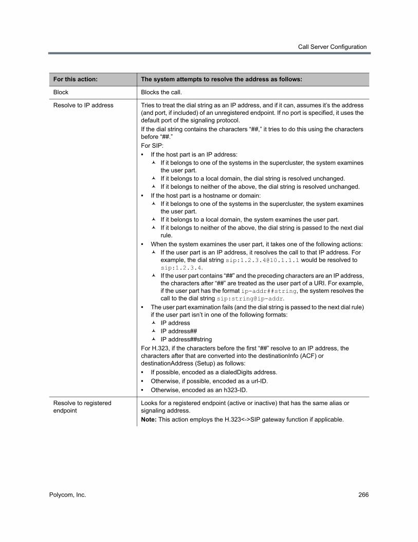
Call Server Configuration
Polycom, Inc. 266
For this action: The system attempts to resolve the address as follows:
Block Blocks the call.
Resolve to IP address Tries to treat the dial string as an IP address, and if it can, assumes it’s the address (and port, if included) of an unregistered endpoint. If no port is specified, it uses the default port of the signaling protocol.
If the dial string contains the characters “##,” it tries to do this using the characters before “##.”
For SIP:
• If the host part is an IP address: If it belongs to one of the systems in the supercluster, the system examines
the user part. If it belongs to a local domain, the dial string is resolved unchanged. If it belongs to neither of the above, the dial string is resolved unchanged.
• If the host part is a hostname or domain: If it belongs to one of the systems in the supercluster, the system examines
the user part. If it belongs to a local domain, the system examines the user part. If it belongs to neither of the above, the dial string is passed to the next dial
rule.
• When the system examines the user part, it takes one of the following actions: If the user part is an IP address, it resolves the call to that IP address. For
example, the dial string sip:[email protected] would be resolved to sip:1.2.3.4.
If the user part contains “##” and the preceding characters are an IP address, the characters after “##” are treated as the user part of a URI. For example, if the user part has the format ip-addr##string, the system resolves the call to the dial string sip:string@ip-addr.
• The user part examination fails (and the dial string is passed to the next dial rule) if the user part isn’t in one of the following formats: IP address IP address## IP address##string
For H.323, if the characters before the first “##” resolve to an IP address, the characters after that are converted into the destinationInfo (ACF) or destinationAddress (Setup) as follows:
• If possible, encoded as a dialedDigits address.
• Otherwise, if possible, encoded as a url-ID.
• Otherwise, encoded as an h323-ID.
Resolve to registered endpoint
Looks for a registered endpoint (active or inactive) that has the same alias or signaling address.
Note: This action employs the H.323<->SIP gateway function if applicable.

Call Server Configuration
Polycom, Inc. 267
Resolve to Lync conference ID
Queries an integrated Lync SIP peer for a Lync AVMCU-based conference with a matching conference ID. This dial rule action enables Polycom RealConnectTM functionality for on-premises Lync systems only; it does not apply to external Lync systems. See Scheduled Conferences with Polycom RealConnect™.
When selected, the following fields are available:
• Conference template
When checked, you can select the conference template used to start the conference. If you leave this option unchanged, the Default conference template configured in Admin > Conference Manager > Conference Settings will be used. Keep in mind that the conference template must specify a Conference mode of AVC only, or the conference will not start. See Considerations and Requirements for Lync 2013 Integration.
• MCU pool order
Select the MCU pool order to use for MCUs that provide Lync AVMCU cascade functionality. If you leave this option unchecked, the dial rule will use the default pool order configured in the Default MCU pool order field on the Admin > Conference Manager > Conference Settings page.
• MCU Affinity Prefer MCU in first MCU pool
The RealPresence DMA system routes the call to the first available MCU in the first MCU pool. If no MCU is available, the system searches the second MCU pool for an available MCU, and so on.
Prefer MCU in first caller’s site
Matches the MCU chosen for the call with the site that the first caller’s endpoint belongs to.
• Available SIP peers / Selected SIP peers selection area
This area lists the names of Available SIP peers and any Selected SIP peers. With the provided arrow buttons, you can move SIP peers between the Available and Selected areas. When the dial rule is executed, the system will query the selected SIP peers to find which one is hosting the Lync conference.
Note: For an external SIP Peer to be listed in the Available SIP peers area, it must be listed on the Network > External SIP Peers page and have the following configuration: A Type of Microsoft The Enable RealConnectTM conferences check box selected in the Lync
Integration tab
Resolve to Lync Conference ID by Conference Auto Attendant
Examines the beginning of the dial string, searching for the longest matching prefix of a defined external Lync system. If a match is found, the dial rule removes the prefix from the dial string and passes the resulting conference ID to the Polycom MCU, which then contacts the CAA of the matched external Lync system.
If an external Lync system is listed on the Admin > Conference Manager > External Lync Systems page, it is available in the Available exernal Lync systems box. You can move external Lync systems to which the rule applies to the Selected external Lync systems box.
A dial rule with this action is required for Polycom MCUs to connect to Lync conferences on external Lync systems.
For this action: The system attempts to resolve the address as follows:

Call Server Configuration
Polycom, Inc. 268
Resolve to service prefix Looks for a service prefix that matches the beginning of the dial string (not counting the URI scheme, if present).
Note: For a SIP peer, the dial string must either include the protocol or consist of only the prefix and user name (no @domain). For instance, if the SIP peer’s prefix is 123, the dial string for a call to [email protected] must be one of the following:
123alice
Resolve to external SIP peer Checks the domain of the dial string against all of the rule’s selected peers, looking for a peer proxy responsible for that domain. If the dial string matches the domain of one of the selected SIP peers, this rule will either successfully route the call, or the call will be aborted; no subsequent dial rules are attempted.
After selecting this action for a rule, select a Routing policy. The policy affects the way the system resolves dial strings to SIP peers:
• All in parallel (forking)
The system uses all SIP peers simultaneously to try to resolve the dial string.
• Weighted round-robin
You can assign each SIP peer a weight in the range 1-100, with a higher weight giving a SIP peer higher priority; the system tries each SIP peer sequentially according to the SIP peer’s assigned weight. You can assign a SIP peer different weights in different dial rules.
After choosing a routing policy, move the SIP peers to which the rule applies from the Available SIP peers box to the Selected SIP peers box. If the Weighted round-robin routing policy is selected, choose a weight for the selected SIP peer using the Edit weight button.
Note: This action employs the H.323<->SIP gateway function if applicable.
Resolve to external gatekeeper
If the dial string appears to be an H.323 alias, simultaneously sends LRQ messages to all of the rule’s selected gatekeepers.
After selecting this action for a rule, move the gatekeepers to which the rule applies from the Available gatekeepers box to the Selected gatekeepers box.
Note: This action employs the H.323<->SIP gateway function if applicable.
Resolve to external address Determines if the dial string is a well-formed instance of an external address type to which the rule applies, and if so, uses the resolution procedures specified in the applicable standard for that address type.
After selecting this action for a rule, select the address type or types to which the rule applies. The address types and applicable standards used to resolve them are:
• SIP URI: RFCs 3261 and 3263
• H.323 url-ID: H.323 specification, Annex O
• H.323 Email-ID: H.225.0 specification, Appendix IV
Resolve to conference room ID
Looks for a conference room (virtual meeting room, or VMR) that matches the dial string.
Resolve to virtual entry queue
Looks for a shared-number entry queue that matches the dial string.
For this action: The system attempts to resolve the address as follows:
Call Server Configuration
Polycom, Inc. 269
See also:
Dial Rules
The Default Dial Plan and Suggestions for Modifications
Preliminary/Postliminary ScriptingA preliminary is an executable script, written in the Javascript language, that defines processing actions (filtering or transformation) to be applied to a dial string before the dial rule’s action is performed.
A postliminary is an executable script, written in the Javascript language, that defines dial string transformations to be applied before querying an external device (gatekeeper, SIP peer, SBC, or MCU).
Transformation scripts output some modification of the DIAL_STRING variable (which is initially set to the dial string being evaluated).
Filtering scripts may pass the dial string on to the dial rule’s action (if the filter criteria aren’t met) or return one of the following:
● NEXT_RULE: Skips the rule being processed and passes the dial string to the next rule.
● BLOCK: Rejects the call.
See Sample Preliminary and Postliminary Scripts for some examples.
Predefined Preliminary/Postliminary Scripting VariablesThe following table describes the predefined variables you can use in a preliminary or postliminary script. The script can evaluate a variable or change its value (the change isn’t preserved after the script completes).
Variable Initial value
CALLER_E164 For H.323 calls only, an array variable initially set to the set of E.164 addresses of the caller. The length of the array is 0 if the caller doesn’t have an E.164 address.
CALLER_H323ID Array variable initially set to the set of H323ID addresses of the caller. The length of the array is 0 if the caller doesn’t have an H323ID address.
CALLER_IS_IPV6 “TRUE” if the caller is an IPv6 endpoint. Blank otherwise.
CALLER_SIP_URI Array variable initially set to the set of SIP URI addresses of the caller. The length of the array is 0 if the caller doesn’t have a SIP URI address.
CALLER_SITE_AREA_CODE Area code of the caller’s site. Blank if the site doesn’t have an area code.
CALLER_SITE_COUNTRY_CODE
Country code of the caller’s site. Blank if the site doesn’t have a country code.
CALLER_SITE_DIGITS The number of subscriber number digits in the caller’s site (that is, the length of a phone number at the site, excluding area code). Blank if the site doesn’t have a number of digits.
CALLER_SITE_NAME The name of the caller’s site.
CALLER_TEL_URI Array variable initially set to the set of Tel URI addresses of the caller. The length of the array is 0 if the caller doesn’t have a Tel URI address.
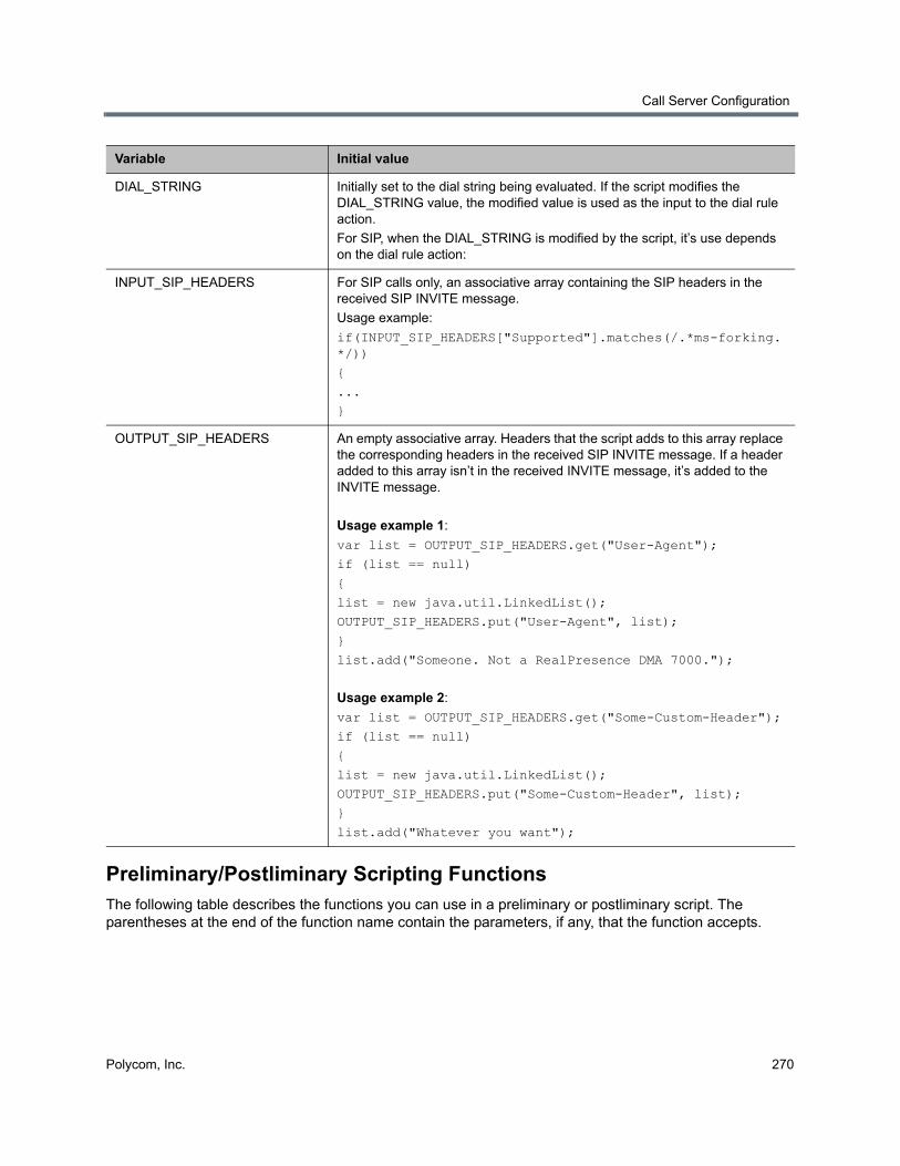
Call Server Configuration
Polycom, Inc. 270
Preliminary/Postliminary Scripting FunctionsThe following table describes the functions you can use in a preliminary or postliminary script. The parentheses at the end of the function name contain the parameters, if any, that the function accepts.
DIAL_STRING Initially set to the dial string being evaluated. If the script modifies the DIAL_STRING value, the modified value is used as the input to the dial rule action.
For SIP, when the DIAL_STRING is modified by the script, it’s use depends on the dial rule action:
INPUT_SIP_HEADERS For SIP calls only, an associative array containing the SIP headers in the received SIP INVITE message.
Usage example:
if(INPUT_SIP_HEADERS["Supported"].matches(/.*ms-forking.*/))
{
...
}
OUTPUT_SIP_HEADERS An empty associative array. Headers that the script adds to this array replace the corresponding headers in the received SIP INVITE message. If a header added to this array isn’t in the received INVITE message, it’s added to the INVITE message.
Usage example 1:
var list = OUTPUT_SIP_HEADERS.get("User-Agent");
if (list == null)
{
list = new java.util.LinkedList();
OUTPUT_SIP_HEADERS.put("User-Agent", list);
}
list.add("Someone. Not a RealPresence DMA 7000.");
Usage example 2:
var list = OUTPUT_SIP_HEADERS.get("Some-Custom-Header");
if (list == null)
{
list = new java.util.LinkedList();
OUTPUT_SIP_HEADERS.put("Some-Custom-Header", list);
}
list.add("Whatever you want");
Variable Initial value
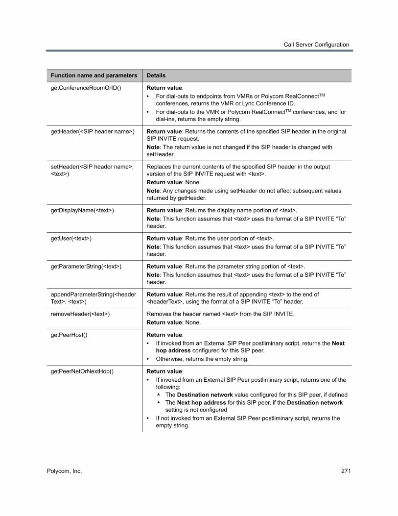
Call Server Configuration
Polycom, Inc. 271
Function name and parameters Details
getConferenceRoomOrID() Return value:
• For dial-outs to endpoints from VMRs or Polycom RealConnectTM conferences, returns the VMR or Lync Conference ID.
• For dial-outs to the VMR or Polycom RealConnectTM conferences, and for dial-ins, returns the empty string.
getHeader(<SIP header name>) Return value: Returns the contents of the specified SIP header in the original SIP INVITE request.
Note: The return value is not changed if the SIP header is changed with setHeader.
setHeader(<SIP header name>, <text>)
Replaces the current contents of the specified SIP header in the output version of the SIP INVITE request with <text>.
Return value: None.
Note: Any changes made using setHeader do not affect subsequent values returned by getHeader.
getDisplayName(<text>) Return value: Returns the display name portion of <text>.
Note: This function assumes that <text> uses the format of a SIP INVITE “To” header.
getUser(<text>) Return value: Returns the user portion of <text>.
Note: This function assumes that <text> uses the format of a SIP INVITE “To” header.
getParameterString(<text>) Return value: Returns the parameter string portion of <text>.
Note: This function assumes that <text> uses the format of a SIP INVITE “To” header.
appendParameterString(<headerText>, <text>)
Return value: Returns the result of appending <text> to the end of <headerText>, using the format of a SIP INVITE “To” header.
removeHeader(<text>) Removes the header named <text> from the SIP INVITE.
Return value: None.
getPeerHost() Return value:
• If invoked from an External SIP Peer postliminary script, returns the Next hop address configured for this SIP peer.
• Otherwise, returns the empty string.
getPeerNetOrNextHop() Return value:
• If invoked from an External SIP Peer postliminary script, returns one of the following: The Destination network value configured for this SIP peer, if defined The Next hop address for this SIP peer, if the Destination network
setting is not configured
• If not invoked from an External SIP Peer postliminary script, returns the empty string.
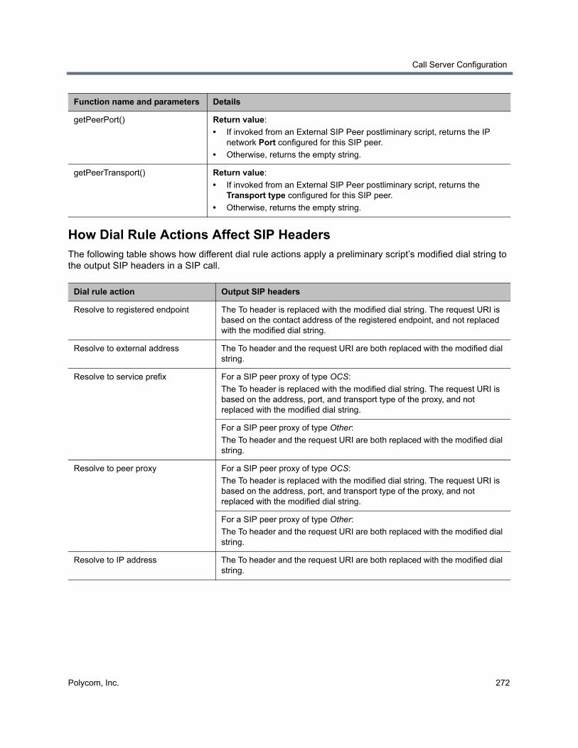
Call Server Configuration
Polycom, Inc. 272
How Dial Rule Actions Affect SIP HeadersThe following table shows how different dial rule actions apply a preliminary script’s modified dial string to the output SIP headers in a SIP call.
getPeerPort() Return value:
• If invoked from an External SIP Peer postliminary script, returns the IP network Port configured for this SIP peer.
• Otherwise, returns the empty string.
getPeerTransport() Return value:
• If invoked from an External SIP Peer postliminary script, returns the Transport type configured for this SIP peer.
• Otherwise, returns the empty string.
Dial rule action Output SIP headers
Resolve to registered endpoint The To header is replaced with the modified dial string. The request URI is based on the contact address of the registered endpoint, and not replaced with the modified dial string.
Resolve to external address The To header and the request URI are both replaced with the modified dial string.
Resolve to service prefix For a SIP peer proxy of type OCS:
The To header is replaced with the modified dial string. The request URI is based on the address, port, and transport type of the proxy, and not replaced with the modified dial string.
For a SIP peer proxy of type Other:
The To header and the request URI are both replaced with the modified dial string.
Resolve to peer proxy For a SIP peer proxy of type OCS:
The To header is replaced with the modified dial string. The request URI is based on the address, port, and transport type of the proxy, and not replaced with the modified dial string.
For a SIP peer proxy of type Other:
The To header and the request URI are both replaced with the modified dial string.
Resolve to IP address The To header and the request URI are both replaced with the modified dial string.
Function name and parameters Details
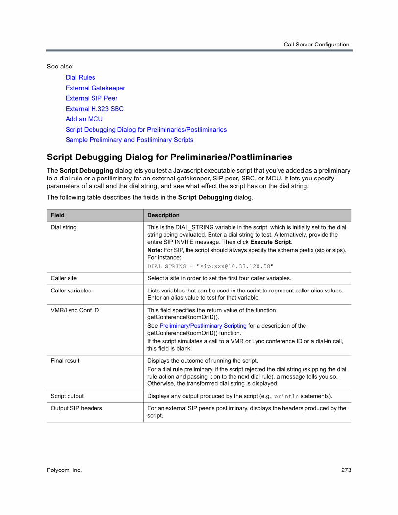
Call Server Configuration
Polycom, Inc. 273
See also:
Dial Rules
External Gatekeeper
External SIP Peer
External H.323 SBC
Add an MCU
Script Debugging Dialog for Preliminaries/Postliminaries
Sample Preliminary and Postliminary Scripts
Script Debugging Dialog for Preliminaries/Postliminaries The Script Debugging dialog lets you test a Javascript executable script that you’ve added as a preliminary to a dial rule or a postliminary for an external gatekeeper, SIP peer, SBC, or MCU. It lets you specify parameters of a call and the dial string, and see what effect the script has on the dial string.
The following table describes the fields in the Script Debugging dialog.
Field Description
Dial string This is the DIAL_STRING variable in the script, which is initially set to the dial string being evaluated. Enter a dial string to test. Alternatively, provide the entire SIP INVITE message. Then click Execute Script.
Note: For SIP, the script should always specify the schema prefix (sip or sips). For instance:
DIAL_STRING = "sip:[email protected]"
Caller site Select a site in order to set the first four caller variables.
Caller variables Lists variables that can be used in the script to represent caller alias values. Enter an alias value to test for that variable.
VMR/Lync Conf ID This field specifies the return value of the function getConferenceRoomOrID().
See Preliminary/Postliminary Scripting for a description of the getConferenceRoomOrID() function.
If the script simulates a call to a VMR or Lync conference ID or a dial-in call, this field is blank.
Final result Displays the outcome of running the script.
For a dial rule preliminary, if the script rejected the dial string (skipping the dial rule action and passing it on to the next dial rule), a message tells you so. Otherwise, the transformed dial string is displayed.
Script output Displays any output produced by the script (e.g., println statements).
Output SIP headers For an external SIP peer’s postliminary, displays the headers produced by the script.
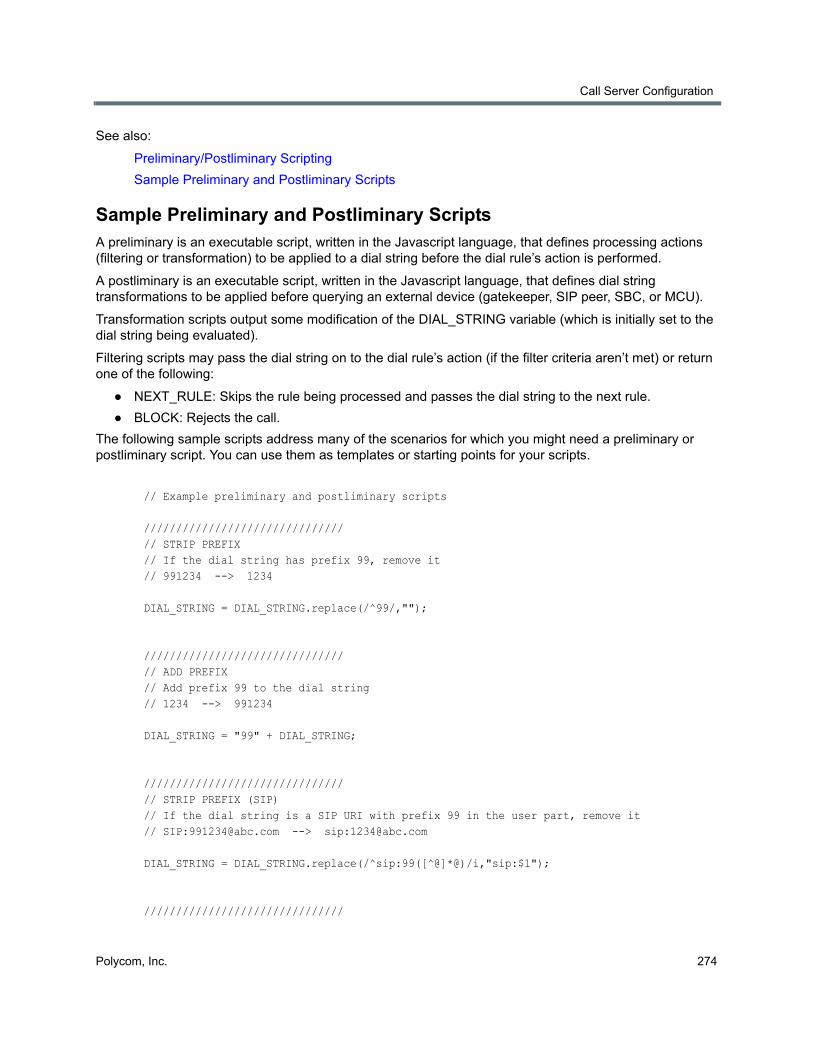
Call Server Configuration
Polycom, Inc. 274
See also:
Preliminary/Postliminary Scripting
Sample Preliminary and Postliminary Scripts
Sample Preliminary and Postliminary ScriptsA preliminary is an executable script, written in the Javascript language, that defines processing actions (filtering or transformation) to be applied to a dial string before the dial rule’s action is performed.
A postliminary is an executable script, written in the Javascript language, that defines dial string transformations to be applied before querying an external device (gatekeeper, SIP peer, SBC, or MCU).
Transformation scripts output some modification of the DIAL_STRING variable (which is initially set to the dial string being evaluated).
Filtering scripts may pass the dial string on to the dial rule’s action (if the filter criteria aren’t met) or return one of the following:
● NEXT_RULE: Skips the rule being processed and passes the dial string to the next rule.
● BLOCK: Rejects the call.
The following sample scripts address many of the scenarios for which you might need a preliminary or postliminary script. You can use them as templates or starting points for your scripts.
// Example preliminary and postliminary scripts
///////////////////////////////// STRIP PREFIX// If the dial string has prefix 99, remove it// 991234 --> 1234
DIAL_STRING = DIAL_STRING.replace(/^99/,"");
///////////////////////////////// ADD PREFIX// Add prefix 99 to the dial string// 1234 --> 991234
DIAL_STRING = "99" + DIAL_STRING;
///////////////////////////////// STRIP PREFIX (SIP)// If the dial string is a SIP URI with prefix 99 in the user part, remove it// SIP:[email protected] --> sip:[email protected]
DIAL_STRING = DIAL_STRING.replace(/^sip:99([^@]*@)/i,"sip:$1");
///////////////////////////////
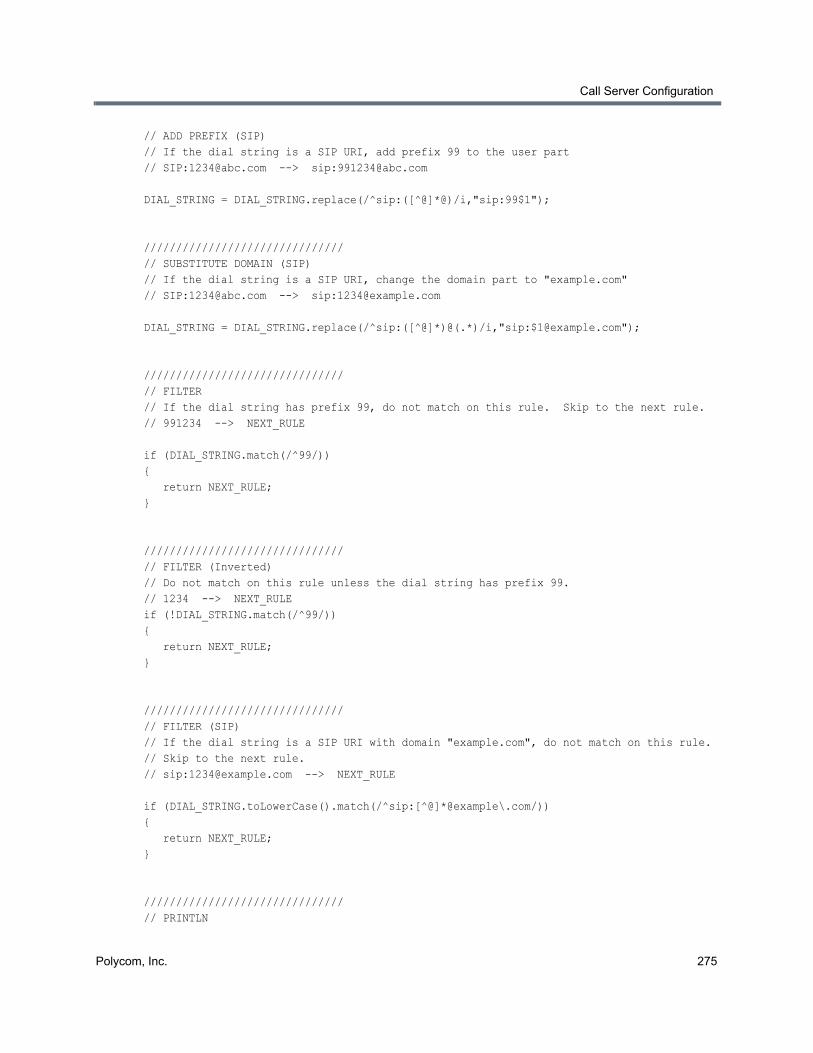
Call Server Configuration
Polycom, Inc. 275
// ADD PREFIX (SIP)// If the dial string is a SIP URI, add prefix 99 to the user part// SIP:[email protected] --> sip:[email protected]
DIAL_STRING = DIAL_STRING.replace(/^sip:([^@]*@)/i,"sip:99$1");
///////////////////////////////// SUBSTITUTE DOMAIN (SIP)// If the dial string is a SIP URI, change the domain part to "example.com"// SIP:[email protected] --> sip:[email protected]
DIAL_STRING = DIAL_STRING.replace(/^sip:([^@]*)@(.*)/i,"sip:[email protected]");
///////////////////////////////// FILTER// If the dial string has prefix 99, do not match on this rule. Skip to the next rule.// 991234 --> NEXT_RULE
if (DIAL_STRING.match(/^99/)){ return NEXT_RULE;}
///////////////////////////////// FILTER (Inverted)// Do not match on this rule unless the dial string has prefix 99.// 1234 --> NEXT_RULEif (!DIAL_STRING.match(/^99/)){ return NEXT_RULE;}
///////////////////////////////// FILTER (SIP)// If the dial string is a SIP URI with domain "example.com", do not match on this rule.// Skip to the next rule.// sip:[email protected] --> NEXT_RULE
if (DIAL_STRING.toLowerCase().match(/^sip:[^@]*@example\.com/)){ return NEXT_RULE;}
///////////////////////////////// PRINTLN
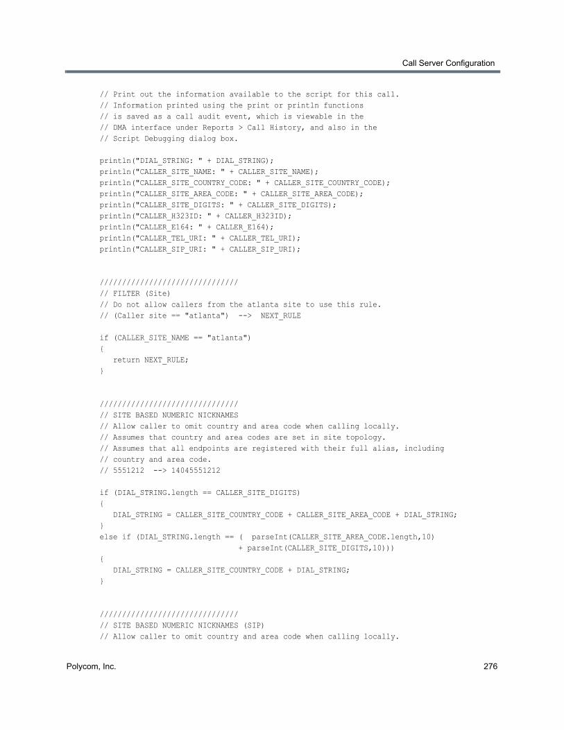
Call Server Configuration
Polycom, Inc. 276
// Print out the information available to the script for this call.// Information printed using the print or println functions// is saved as a call audit event, which is viewable in the// DMA interface under Reports > Call History, and also in the// Script Debugging dialog box.
println("DIAL_STRING: " + DIAL_STRING);println("CALLER_SITE_NAME: " + CALLER_SITE_NAME);println("CALLER_SITE_COUNTRY_CODE: " + CALLER_SITE_COUNTRY_CODE);println("CALLER_SITE_AREA_CODE: " + CALLER_SITE_AREA_CODE);println("CALLER_SITE_DIGITS: " + CALLER_SITE_DIGITS);println("CALLER_H323ID: " + CALLER_H323ID);println("CALLER_E164: " + CALLER_E164);println("CALLER_TEL_URI: " + CALLER_TEL_URI);println("CALLER_SIP_URI: " + CALLER_SIP_URI);
///////////////////////////////// FILTER (Site)// Do not allow callers from the atlanta site to use this rule.// (Caller site == "atlanta") --> NEXT_RULE
if (CALLER_SITE_NAME == "atlanta"){ return NEXT_RULE;}
///////////////////////////////// SITE BASED NUMERIC NICKNAMES// Allow caller to omit country and area code when calling locally.// Assumes that country and area codes are set in site topology.// Assumes that all endpoints are registered with their full alias, including// country and area code.// 5551212 --> 14045551212
if (DIAL_STRING.length == CALLER_SITE_DIGITS){ DIAL_STRING = CALLER_SITE_COUNTRY_CODE + CALLER_SITE_AREA_CODE + DIAL_STRING;} else if (DIAL_STRING.length == ( parseInt(CALLER_SITE_AREA_CODE.length,10) + parseInt(CALLER_SITE_DIGITS,10))){ DIAL_STRING = CALLER_SITE_COUNTRY_CODE + DIAL_STRING;}
///////////////////////////////// SITE BASED NUMERIC NICKNAMES (SIP)// Allow caller to omit country and area code when calling locally.
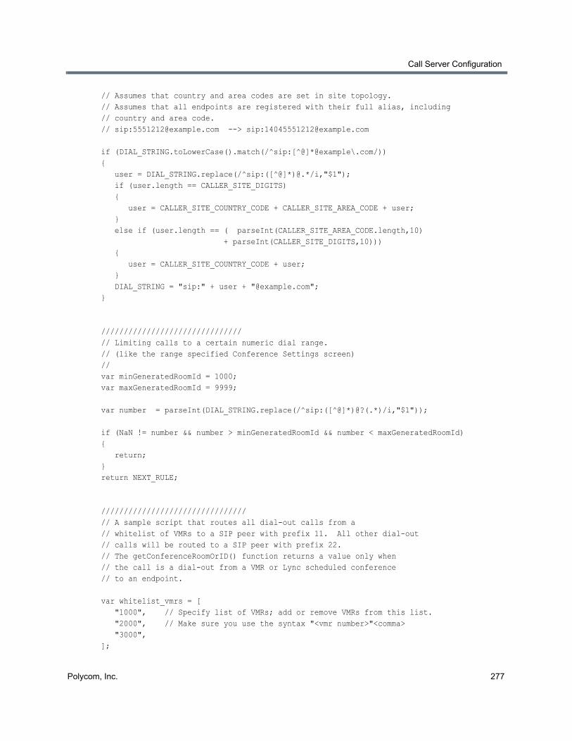
Call Server Configuration
Polycom, Inc. 277
// Assumes that country and area codes are set in site topology.// Assumes that all endpoints are registered with their full alias, including// country and area code.// sip:[email protected] --> sip:[email protected]
if (DIAL_STRING.toLowerCase().match(/^sip:[^@]*@example\.com/)){ user = DIAL_STRING.replace(/^sip:([^@]*)@.*/i,"$1"); if (user.length == CALLER_SITE_DIGITS) { user = CALLER_SITE_COUNTRY_CODE + CALLER_SITE_AREA_CODE + user; } else if (user.length == ( parseInt(CALLER_SITE_AREA_CODE.length,10) + parseInt(CALLER_SITE_DIGITS,10))) { user = CALLER_SITE_COUNTRY_CODE + user; } DIAL_STRING = "sip:" + user + "@example.com";}
///////////////////////////////// Limiting calls to a certain numeric dial range.// (like the range specified Conference Settings screen)// var minGeneratedRoomId = 1000;var maxGeneratedRoomId = 9999;
var number = parseInt(DIAL_STRING.replace(/^sip:([^@]*)@?(.*)/i,"$1"));
if (NaN != number && number > minGeneratedRoomId && number < maxGeneratedRoomId){ return;}return NEXT_RULE;
////////////////////////////////// A sample script that routes all dial-out calls from a// whitelist of VMRs to a SIP peer with prefix 11. All other dial-out// calls will be routed to a SIP peer with prefix 22.// The getConferenceRoomOrID() function returns a value only when// the call is a dial-out from a VMR or Lync scheduled conference// to an endpoint.
var whitelist_vmrs = [ "1000", // Specify list of VMRs; add or remove VMRs from this list. "2000", // Make sure you use the syntax "<vmr number>"<comma> "3000", ];
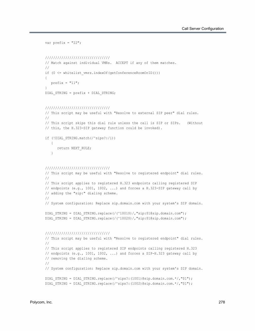
Call Server Configuration
Polycom, Inc. 278
var prefix = "22";
////////////////////////////////// Match against individual VMRs. ACCEPT if any of them matches.//if (0 <= whitelist_vmrs.indexOf(getConferenceRoomOrID())){ prefix = "11";}DIAL_STRING = prefix + DIAL_STRING;
////////////////////////////////// This script may be useful with "Resolve to external SIP peer" dial rules.//// This script skips this dial rule unless the call is SIP or SIPs. (Without// this, the H.323-SIP gateway function could be invoked).
if (!DIAL_STRING.match(/^sips?:/i)) { return NEXT_RULE; }
////////////////////////////////// This script may be useful with "Resolve to registered endpoint" dial rules.//// This script applies to registered H.323 endpoints calling registered SIP // endpoints (e.g., 1001, 1002, ...) and forces a H.323-SIP gateway call by // adding the "sip:" dialing scheme.//// System configuration: Replace sip.domain.com with your system's SIP domain.
DIAL_STRING = DIAL_STRING.replace(/(^1001$)/,"sip:[email protected]");DIAL_STRING = DIAL_STRING.replace(/(^1002$)/,"sip:[email protected]");
////////////////////////////////// This script may be useful with "Resolve to registered endpoint" dial rules.//// This script applies to registered SIP endpoints calling registered H.323// endpoints (e.g., 1001, 1002, ...) and forces a SIP-H.323 gateway call by// removing the dialing scheme.//// System configuration: Replace sip.domain.com with your system's SIP domain.
DIAL_STRING = DIAL_STRING.replace(/^sips?:(1001)@sip.domain.com.*/,"$1");DIAL_STRING = DIAL_STRING.replace(/^sips?:(1002)@sip.domain.com.*/,"$1");
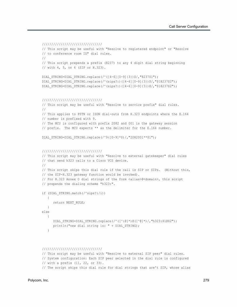
Call Server Configuration
Polycom, Inc. 279
////////////////////////////////// This script may be useful with "Resolve to registered endpoint" or "Resolve// to conference room ID" dial rules.//// This script prepends a prefix (8237) to any 4 digit dial string beginning // with 4, 5, or 6 (SIP or H.323).
DIAL_STRING=DIAL_STRING.replace(/^([4-6][0-9]{3})$/,"8237$1");DIAL_STRING=DIAL_STRING.replace(/^(sips?:)([4-6][0-9]{3})$/,"$18237$2");DIAL_STRING=DIAL_STRING.replace(/^(sips?:)([4-6][0-9]{3})@/,"$18237$2");
////////////////////////////////// This script may be useful with "Resolve to service prefix" dial rules.//// This applies to PSTN or ISDN dial-outs from H.323 endpoints where the E.164// number is prefixed with 9.// The MCU is configured with prefix 2082 and 001 is the gateway session // prefix. The MCU expects ** as the delimiter for the E.164 number.
DIAL_STRING=DIAL_STRING.replace(/^9([0-9]*$)/,"2082001**$1");
////////////////////////////////// This script may be useful with "Resolve to external gatekeeper" dial rules// that send h323 calls to a Cisco VCS device.//// This script skips this dial rule if the call is SIP or SIPs. (Without this,// the SIP-H.323 gateway function would be invoked).// For H.323 Annex O dial strings of the form <alias>@<domain>, this script // prepends the dialing scheme "h323:".
if (DIAL_STRING.match(/^sips?:/i)) { return NEXT_RULE; }else { DIAL_STRING=DIAL_STRING.replace(/^([^:@]*)@([^@]*)/,"h323:$1@$2"); println("new dial string is: " + DIAL_STRING); }
////////////////////////////////// This script may be useful with "Resolve to external SIP peer" dial rules.// System configuration: Each SIP peer selected in the dial rule is configured// with a prefix (11, 22, or 33).// The script skips this dial rule for dial strings that are't SIP, whose alias
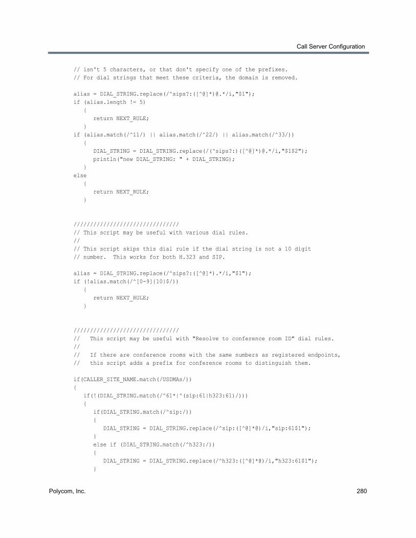
Call Server Configuration
Polycom, Inc. 280
// isn't 5 characters, or that don't specify one of the prefixes.// For dial strings that meet these criteria, the domain is removed. alias = DIAL_STRING.replace(/^sips?:([^@]*)@.*/i,"$1");if (alias.length != 5) { return NEXT_RULE; }if (alias.match(/^11/) || alias.match(/^22/) || alias.match(/^33/)) { DIAL_STRING = DIAL_STRING.replace(/(^sips?:)([^@]*)@.*/i,"$1$2"); println("new DIAL_STRING: " + DIAL_STRING); }else { return NEXT_RULE; }
////////////////////////////////// This script may be useful with various dial rules.//// This script skips this dial rule if the dial string is not a 10 digit// number. This works for both H.323 and SIP.
alias = DIAL_STRING.replace(/^sips?:([^@]*).*/i,"$1");if (!alias.match(/^[0-9]{10}$/)) { return NEXT_RULE; }
////////////////////////////////// This script may be useful with "Resolve to conference room ID" dial rules.//// If there are conference rooms with the same numbers as registered endpoints,// this script adds a prefix for conference rooms to distinguish them.
if(CALLER_SITE_NAME.match(/USDMAs/)){ if(!(DIAL_STRING.match(/^61*|^(sip:61|h323:61)/))) { if(DIAL_STRING.match(/^sip:/)) { DIAL_STRING = DIAL_STRING.replace(/^sip:([^@]*@)/i,"sip:61$1"); } else if (DIAL_STRING.match(/^h323:/)) { DIAL_STRING = DIAL_STRING.replace(/^h323:([^@]*@)/i,"h323:61$1"); }
Call Server Configuration
Polycom, Inc. 281
else { DIAL_STRING = "61" + DIAL_STRING; } } println("New translated DIAL_STRING: " + DIAL_STRING);}if(!(DIAL_STRING.match(/^61*|^(sip:61|h323:61)/))){ return NEXT_RULE;}
See also:
Preliminary/Postliminary Scripting
Script Debugging Dialog for Preliminaries/Postliminaries
Hunt GroupsA hunt group is a set of endpoints that share an alias or aliases. Hunt groups can be used to define a dial string shared by a group of people, such as a technical support number. When the Polycom RealPresence DMA system Call Server resolves a dial string to the hunt group’s alias, it selects a member of the group and tries to terminate the call to that member.
The system selects hunt group members in round-robin fashion. It skips members that are in a call or have unconditional call forwarding enabled. If the selected group member rejects the call or doesn’t answer before the timeout, the system tries the next group member.
If all members have been attempted (or skipped) without successfully terminating the call, the system sends the BUSY message to the caller.
Registered endpoints can add themselves to a hunt group by dialing the vertical service code (VSC) for joining (default is *71) followed by the hunt group alias. They can leave a hunt group by dialing the VSC for leaving (default is *72) followed by the hunt group alias. An endpoint can belong to multiple hunt groups.
The Hunt Groups page lists the defined hunt groups and lets you add, edit, and delete hunt groups. The following table describes the fields in the list.
See also:
Call Server Configuration
Edit Hunt Group Dialog
Column Description
Name Hunt group name.
Description Brief description of the hunt group.
Aliases The aliases (dial strings) that resolve to this hunt group.
Members The endpoints included in the hunt group.
Enabled Indicates whether the hunt group is being used.
Call Server Configuration
Polycom, Inc. 282
Add Hunt Group DialogThe Add Hunt Group dialog lets you define a new hunt group in the system and add members to it. The following table describes the fields in the dialog.
See also:
Hunt Groups
Add Alias Dialog
Edit Alias Dialog
Edit Hunt Group DialogThe Edit Hunt Group dialog lets you modify the selected hunt group and add or remove members. The following table describes the fields in the dialog.
Field Description
General Info
Name Hunt group name.
Description The text description displayed in the Hunt Groups list.
Enabled Clearing this check box lets you define a new hunt group without putting it immediately into service.
No answer timeout Number of seconds to wait for a hunt group member to answer a call before giving up and trying another member.
Aliases Lists the aliases (dial strings) that resolve to this hunt group. Click Add to add an alias. Click Edit or Delete to change or remove the selected alias.
Hunt Group Members
Search Search for endpoints by alias, IP address, or registration status.
Available endpoints Lists the endpoints that match the search criteria.
Member endpoints Lists the endpoints to include in the hunt group. Use the arrow buttons to move endpoints from one list to the other.
Field Description
General Info
Name Hunt group name.
Description The text description displayed in the Hunt Groups list.
Enabled Clearing this check box lets you stop using a hunt group without deleting it.
No answer timeout Number of seconds to wait for a hunt group member to answer a call before giving up and trying another member.
Call Server Configuration
Polycom, Inc. 283
See also:
Hunt Groups
Add Alias DialogThe Add Alias dialog lets you add an alias value to the hunt group. Enter the alias in the Value box and click OK.
Aliases should be specified by their fully qualified dial string. For example, to specify that H.323 callers can call the hunt group by dialing 1234, enter 1234. To specify that SIP callers can call the hunt group by dialing 1234, enter sip:[email protected].
See also:
Hunt Groups
Add Hunt Group Dialog
Edit Hunt Group Dialog
Edit Alias DialogThe Edit Alias dialog lets you change an alias value assigned to the hunt group. Edit the alias in the Value box and click OK.
Aliases should be specified by their fully qualified dial string. For example, to specify that H.323 callers can call the hunt group by dialing 1234, enter 1234. To specify that SIP callers can call the hunt group by dialing 1234, enter sip:[email protected].
See also:
Hunt Groups
Add Hunt Group Dialog
Edit Hunt Group Dialog
Device AuthenticationDevice authentication enhances security by requiring devices registering with or calling the Polycom RealPresence DMA system to provide credentials that the system can authenticate. In turn, the Polycom RealPresence DMA system may need to authenticate itself to an external SIP peer or gatekeeper.
Aliases Lists the aliases (dial strings) that resolve to this hunt group. Click Add to add an alias. Click Edit or Delete to change or remove the selected alias.
Hunt Group Members
Search Search for endpoints by alias, IP address, or registration status.
Available endpoints Lists the endpoints that match the search criteria.
Member endpoints Lists the endpoints to include in the hunt group. Use the arrow buttons to move endpoints from one list to the other.
Field Description
Call Server Configuration
Polycom, Inc. 284
All authentication configurations are supercluster-wide, but note that the default realm for SIP device authentication is the cluster’s domain as specified on the Admin > Local Cluster > Network Settings page (or sip.dma if no domain is specified). This allows each cluster in a supercluster to have its own realm for challenges.
The Device Authentication page has two tabs, Inbound Authentication and Shared Outbound Authentication.
Inbound Authentication
On the Inbound Authentication tab, you can:
● Configure specific SIP digest authentication settings for SIP devices.
● Maintain the Call Server’s local inbound device authentication list. This list is used for both H.235 authentication (H.323 devices) and SIP digest authentication (SIP devices).
● Click the Signaling settings link to go to the Signaling Settings page, where you actually enable device authentication for H.323, SIP, or both (see Signaling Settings).
Shared Outbound Authentication
On the Shared Outbound Authentication tab, you can maintain the Call Server’s general list of authentication credentials, which it uses to authenticate itself on behalf of calling devices to external SIP peers for which the appropriate device-specific credentials haven’t been defined.
The Call Server intercepts and responds to authentication challenges from SIP peers on behalf of some or all devices calling though the Call Server. This feature allows authentication security between the Call Server and its peers to be completely separate from security between the endpoints and the Call Server.
When you add an external SIP peer, you can specify whether the Call Server handles challenges (401 and 407) on behalf of the source of the call or passes them on to the source of the call. You can also define authentication credentials specifically for that SIP peer. See Add External SIP Peer Dialog.
The following table describes the fields on the Device Authentication page.
Note: Neighbor gatekeepers and H.235 authentication
For H.323, when you add a neighbor gatekeeper, you can configure the system to send its H.235 credentials when it sends address resolution requests to that gatekeeper. See Add External Gatekeeper Dialog.
Field Description
Inbound Authentication
SIP device authentication settings
Use default realm This option, the default, sets the realm for the Call Server to the cluster’s domain as specified on the Network Settings page (allowing each cluster of a supercluster to have its own realm). If no domain is specified on the Network Settings page, the default realm value is sip.dma.
Clear the check box to change the string in the Realm field.
Call Server Configuration
Polycom, Inc. 285
See also:
Call Server Configuration
Add Device Authentication Dialog
Edit Device Authentication Dialog
Add Device Authentication DialogThe Add Device Authentication dialog appears when you click Add on the Device Authentication page while the Inbound Authentication tab is selected. It lets you add a device’s authentication credentials to the list of entries against which the Call Server checks a device’s credentials.
The following table describes the fields in the Add Device Authentication dialog.
Realm The realm string in an authentication challenge tells the challenged device the protection domain for which it must provide credentials.
Generally, it includes the domain label of the Call Server. See RFC 2617 and RFC 3261.
If you specify a realm instead of using the default, the realm you specify is used for all clusters in the supercluster.
Enable proxy authentication
Configures the Call Server to respond to unauthenticated requests with 407 (Proxy Authentication Required).
If turned off, the Call Server responds to unauthenticated requests with 401 (Unauthorized).
Authentication valid time (seconds)
Specifies the time period within which the Call Server doesn’t re-challenge a device that previously authenticated itself.
(table of authentication entries) Lists the inbound device authentication entries against which the Call Server checks a device’s credentials.
Click Add to add a device’s credentials to the list. Click Edit or Delete to change or remove the selected entry.
Shared Outbound Authentication
(table of authentication entries) Lists the authentication credential entries defined for general use by the Call Server to authenticate its requests, showing the realm in which the entry is valid and the user name. You can add, edit, or delete credential entries.
Use the Realm or Name field and Search button above the list to narrow the list.
When choosing authentication credentials to present to an external SIP peer, the Call Server looks first for an appropriate entry specific to that SIP peer (see Edit External SIP Peer Dialog). If there is none with the correct realm, it looks at the entries listed here.
Field Description
Call Server Configuration
Polycom, Inc. 286
See also:
Device Authentication
Edit Device Authentication DialogThe Edit Device Authentication dialog appears when you click Edit on the Device Authentication page while an entry on the Inbound Authentication tab is selected. It lets you edit the authentication credentials for the selected device.
The following table describes the fields in the Edit Device Authentication dialog.
See also:
Device Authentication
Registration PolicyOn the Registration Policy page, you can specify policies to control registration by endpoints. To do so, you define the following:
● Compliance policy: Write an executable script (using the Javascript language) that specifies the criteria for determining whether an endpoint is compliant or noncompliant with the registration policy.
Field Description
Device Authentication
Name The name that the device includes in registration and signaling requests or responses to authentication challenges.
Note: The name and password for a device are whatever values the person who configured the device specified. They don’t uniquely identify a specific device; multiple devices can have the same name and password.
Password
Confirm password
The password that the device includes in registration and signaling requests or responses to authentication challenges.
Field Description
Device Authentication
Name The name that the device includes in registration and signaling requests or responses to authentication challenges.
Note: The name and password for a device are whatever values the person who configured it specified. They don’t uniquely identify a specific device; multiple devices can have the same name and password.
Password
Confirm password
The password that the device includes in registration and signaling requests or responses to authentication challenges.

Call Server Configuration
Polycom, Inc. 287
● Admission policy: Select the action to be taken when an endpoint is compliant, and the action to be taken when an endpoint is noncompliant.
The actions that may be taken are:
Accept registration — The endpoint’s registration request is accepted and its status becomes Active (see Endpoints for more information about endpoint status values).
Block registration — The endpoint’s registration request is rejected and its status becomes Blocked. The system automatically rejects registration attempts (and unregistration attempts) from blocked endpoints without applying the registration policy. Their status remains unchanged until you manually unblock them.
Reject registration — The endpoint’s registration request is rejected and its status remains not registered. It doesn’t appear in the Endpoints list. Whether it can make and receive calls depends on the system’s rogue call policy (see Call Server Settings). If the endpoint sends another registration request, the registration policy is applied to that request.
Quarantine registration — The endpoint’s registration request is accepted, but its status becomes Quarantined. It can’t make or receive calls. The system processes registration attempts (and unregistration attempts) from quarantined endpoints, but doesn’t apply the registration policy. Their status remains either Quarantined if registered or Quarantined (Inactive) if unregistered until you manually remove them from quarantine.
You can also specify whether the policy is to be applied only to new registrations, or also to re-registrations with changed properties.
The following table describes the fields on the page.
Field Description
Allow site-less registrations If this option is selected, endpoints that don’t belong to a configured site or territory can register with the Call Server. Otherwise, only endpoints in a subnet configured in the site topology can register.
When compliant Select the action to take when the registration policy script returns COMPLIANT.
When noncompliant Select the action to take when the registration policy script returns NONCOMPLIANT.
Policy Applies Select whether to apply the registration policy script only to new registrations or also to changed re-registrations.
If you choose the latter, you can optionally select Ignore IP and port changes so that the registration policy script is not applied if those are the only changes.
Registration policy compliance script
Type (or paste) the registration policy script you want to apply. Then click Debug this Script to test the script with various variables.
Click Reapply Policy to run the script, applying any changes you’ve made to existing registered endpoints.
Inactive registration deletion days Select to specify that endpoints whose status is Inactive (that is, their registrations have expired) are deleted from the system after the specified number of days.
Some dial rule actions, such as Resolve to registered endpoint, can route calls to endpoints with an inactive registration. Deleting the registration record is the only way to prevent resolution to an inactive endpoint.
Call Server Configuration
Polycom, Inc. 288
See also:
Call Server Configuration
Script Debugging Dialog for Registration Policy Scripts
Sample Registration Policy Scripts
Registration Policy ScriptingA registration policy script is an executable script, written in the Javascript language, that defines the criteria to be applied to registration requests in order to determine what to do with them. The script can specify any number of criteria, and they can be as broad or narrow as you want.
A script can return COMPLIANT or NONCOMPLIANT. The corresponding settings on the Registration Policy page let you specify what action to take for each of these return values.
A script can also assign a value (up to 1000 characters) to the EP_EXCEPTION variable. This variable’s initial value is blank (empty string). Assigning a non-blank value to it causes an exception to be recorded for the endpoint being processed. Exceptions appear on the Endpoints page, and you can search for endpoints with exceptions. See Endpoints.
Exceptions can serve a variety of purposes, from specifying the reason a registration was rejected to simply recording information about the request for future reference. For instance, you may want all endpoints to conform to a specific alias dial string pattern, but not want to quarantine those that don’t comply. Assigning an exception to non-compliant endpoints allows you to find them on the Endpoints page so that you can contact the owners.
The following table describes the other predefined variables you can use in a registration policy script. Each time the script runs, it gets the initial values for these variables from the registration request being processed. The script can evaluate a variable or change its value (the change isn’t preserved after the script completes).
Note: Registration policy scripting tips
When you click Update, a Javascript parser evaluates the registration policy script. If there is a syntax error in the script, an error message reports the problem and asks if you still want to update. You may do so in order to save a work in progress, but the script won’t be used until it’s valid. Note that the parser’s capabilities are limited and its error messages may not pinpoint the problem as clearly as you might like. More capable script testing services are available, such as JSLint.
We also encourage you to use Debug this Script to test your script thoroughly with various dial strings and other parameters. See Script Debugging Dialog for Preliminaries/Postliminaries.
See Sample Registration Policy Scripts for some script examples.
Variable Initial value
EP_DEFINED_IN_CMA “TRUE” if the Polycom RealPresence DMA system is integrated with a RealPresence Resource Manager system and the endpoint is defined in that system.
EP_H323_DIALEDDIGITS_ALIAS Endpoint alias value associated with H.323 dialedDigits or blank.
This is an array that can contain multiple values. Separate the values with commas.
Call Server Configuration
Polycom, Inc. 289
EP_H323_EMAIL_ID_ALIAS Endpoint alias value associated with H.323 email-ID or blank.
This is an array that can contain multiple values. Separate the values with commas.
EP_H323_H323_ID_ALIAS Endpoint alias value associated with H.323 H323-ID or blank.
This is an array that can contain multiple values. Separate the values with commas.
EP_H323_TRANSPORTID_ALIAS Endpoint alias value associated with H.323 transportID or blank.
This is an array that can contain multiple values. Separate the values with commas.
EP_H323_URL_ID_ALIAS Endpoint alias value associated with H.323 URL-ID or blank.
This is an array that can contain multiple values. Separate the values with commas.
EP_IP Endpoint IP address. Enter it here in normal dot or colon notation (such as 1.2.3.4 for IPv4).
In the script, this is represented as an array. If the IP address is IPv4, there are 4 elements in the array. If the IP address is IPv6, there are 8 elements in the array.
EP_IS_IPV4 “TRUE” if EP_IP is an IPv4 address. Blank otherwise.
EP_IS_IPV6 “TRUE” if EP_IP is an IPv6 address. Blank otherwise.
EP_MODEL Endpoint model.
EP_OWNER Endpoint owner.
EP_OWNER_DOMAIN Endpoint owner's domain.
EP_REG_IS_H323 “TRUE” if the registration request uses H.323 signaling. Blank otherwise.
EP_REG_IS_SIP “TRUE” if the registration request uses SIP signaling. Blank otherwise.
EP_SIP_SIP_URI_ALIAS Endpoint alias value associated with SIP sip: URI or blank.
This is an array that can contain multiple values. Separate the values with commas.
EP_SIP_SIPS_URI_ALIAS Endpoint alias value associated with SIP SIPS: URI or blank.
This is an array that can contain multiple values. Separate the values with commas.
EP_SIP_TEL_URI_ALIAS Endpoint alias value associated with SIP TEL: URI or blank.
This is an array that can contain multiple values. Separate the values with commas.
EP_VERSION Endpoint software version number.
REG_IS_PERMANENT “TRUE” if endpoint is already permanently registered. Blank otherwise.
Variable Initial value
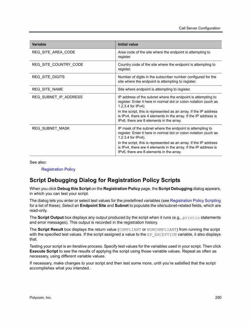
Call Server Configuration
Polycom, Inc. 290
See also:
Registration Policy
Script Debugging Dialog for Registration Policy ScriptsWhen you click Debug this Script on the Registration Policy page, the Script Debugging dialog appears, in which you can test your script.
The dialog lets you enter or select test values for the predefined variables (see Registration Policy Scripting for a list of these). Select an Endpoint Site and Subnet to populate the site/subnet-related fields, which are read-only.
The Script Output box displays any output produced by the script when it runs (e.g., println statements and error messages). This output is recorded in the registration history.
The Script Result box displays the return value (COMPLIANT or NONCOMPLIANT) from running the script with the specified test values. If the script assigned a value to the EP_EXCEPTION variable, it also displays that.
Testing your script is an iterative process. Specify test values for the variables used in your script. Then click Execute Script to see the results of applying the script using those variable values. Repeat as often as necessary, using different variable values.
If necessary, make changes to your script and then test some more, until you’re satisfied that the script accomplishes what you intended.
REG_SITE_AREA_CODE Area code of the site where the endpoint is attempting to register.
REG_SITE_COUNTRY_CODE Country code of the site where the endpoint is attempting to register.
REG_SITE_DIGITS Number of digits in the subscriber number configured for the site where the endpoint is attempting to register.
REG_SITE_NAME Site where endpoint is attempting to register.
REG_SUBNET_IP_ADDRESS IP address of the subnet where the endpoint is attempting to register. Enter it here in normal dot or colon notation (such as 1.2.3.4 for IPv4).
In the script, this is represented as an array. If the IP address is IPv4, there are 4 elements in the array. If the IP address is IPv6, there are 8 elements in the array.
REG_SUBNET_MASK IP mask of the subnet where the endpoint is attempting to register. Enter it here in normal dot or colon notation (such as 1.2.3.4 for IPv4).
In the script, this is represented as an array. If the IP address is IPv4, there are 4 elements in the array. If the IP address is IPv6, there are 8 elements in the array.
Variable Initial value
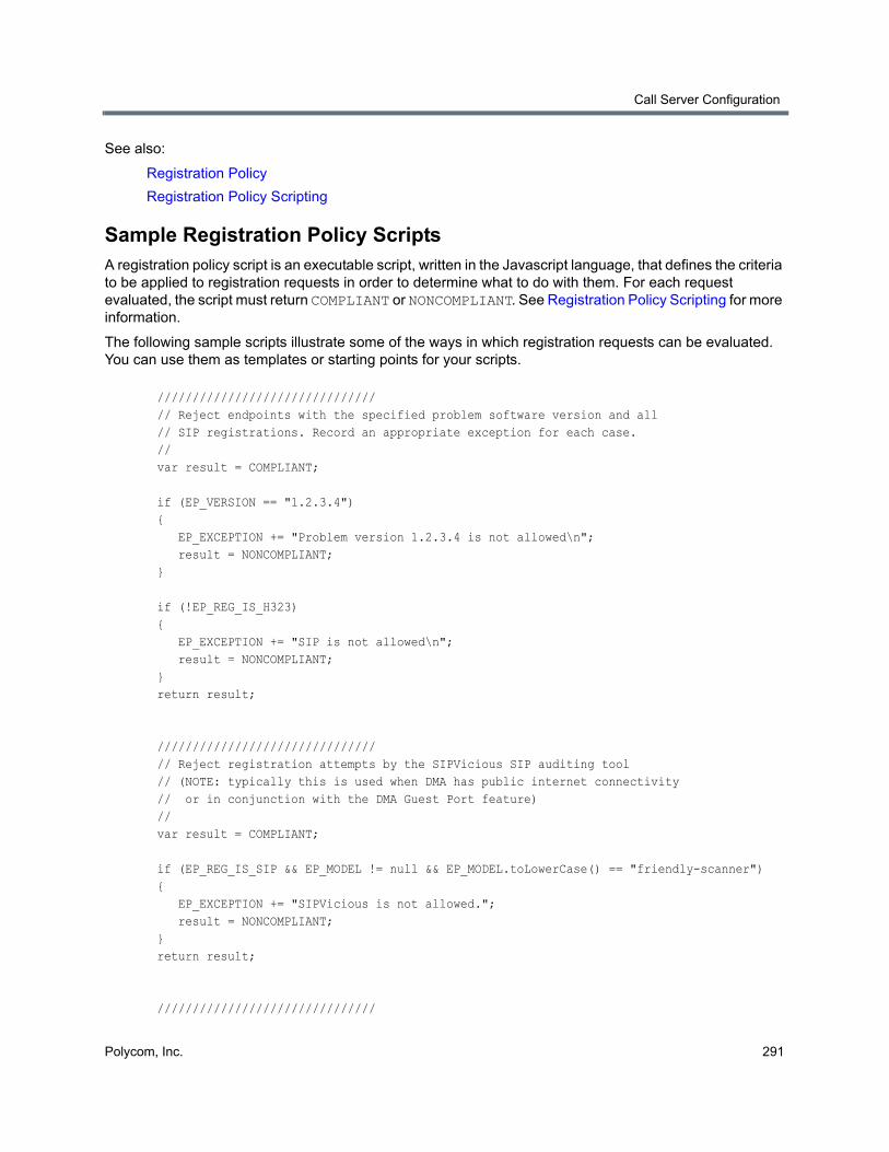
Call Server Configuration
Polycom, Inc. 291
See also:
Registration Policy
Registration Policy Scripting
Sample Registration Policy ScriptsA registration policy script is an executable script, written in the Javascript language, that defines the criteria to be applied to registration requests in order to determine what to do with them. For each request evaluated, the script must return COMPLIANT or NONCOMPLIANT. See Registration Policy Scripting for more information.
The following sample scripts illustrate some of the ways in which registration requests can be evaluated. You can use them as templates or starting points for your scripts.
///////////////////////////////// Reject endpoints with the specified problem software version and all // SIP registrations. Record an appropriate exception for each case. // var result = COMPLIANT;
if (EP_VERSION == "1.2.3.4"){ EP_EXCEPTION += "Problem version 1.2.3.4 is not allowed\n"; result = NONCOMPLIANT;}
if (!EP_REG_IS_H323){ EP_EXCEPTION += "SIP is not allowed\n"; result = NONCOMPLIANT;}return result;
///////////////////////////////// Reject registration attempts by the SIPVicious SIP auditing tool// (NOTE: typically this is used when DMA has public internet connectivity// or in conjunction with the DMA Guest Port feature)//var result = COMPLIANT;
if (EP_REG_IS_SIP && EP_MODEL != null && EP_MODEL.toLowerCase() == "friendly-scanner") { EP_EXCEPTION += "SIPVicious is not allowed."; result = NONCOMPLIANT; } return result;
///////////////////////////////
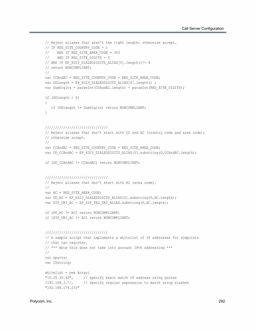
Call Server Configuration
Polycom, Inc. 292
// Reject aliases that aren't the right length; otherwise accept.// IF REG_SITE_COUNTRY_CODE = 1// AND IF REG_SITE_AREA_CODE = 303// AND IF REG_SITE_DIGITS = 4// AND IF EP_H323_DIALEDDIGITS_ALIAS[0].length()!= 8// return NONCOMPLIANT;//var CCAndAC = REG_SITE_COUNTRY_CODE + REG_SITE_AREA_CODE;var DDlength = EP_H323_DIALEDDIGITS_ALIAS[0].length() ;var SumDigits = parseInt(CCAndAC.length) + parseInt(REG_SITE_DIGITS);
if (DDlength > 0){ if (DDlength != SumDigits) return NONCOMPLIANT;}
///////////////////////////////// Reject aliases that don't start with CC and AC (country code and area code);// otherwise accept.//var CCAndAC = REG_SITE_COUNTRY_CODE + REG_SITE_AREA_CODE;var DD_CCAndAC = EP_H323_DIALEDDIGITS_ALIAS[0].substring(0,CCAndAC.length);
if (DD_CCAndAC != CCAndAC) return NONCOMPLIANT;
///////////////////////////////// Reject aliases that don't start with AC (area code).//var AC = REG_SITE_AREA_CODE;var DD_AC = EP_H323_DIALEDDIGITS_ALIAS[0].substring(0,AC.length);var SIP_URI_AC = EP_SIP_TEL_URI_ALIAS.substring(0,AC.length);
if (DD_AC != AC) return NONCOMPLIANT;if (SIP_URI_AC != AC) return NONCOMPLIANT;
///////////////////////////////// A sample script that implements a whitelist of IP addresses for endpoints // that can register.// *** Note this does not take into account IPv6 addressing ***//var nparts;var IPstring;
whitelist = new Array("10.20.30.40", // specify exact match IP address using quotes/192.168.3.*/, // specify regular expression to match using slashes"192.168.174.233"
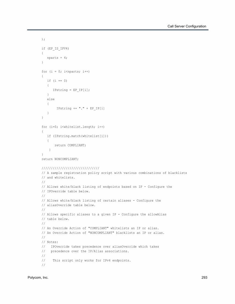
Call Server Configuration
Polycom, Inc. 293
);
if (EP_IS_IPV4) { nparts = 4;}
for (i = 0; i<nparts; i++) { if (i == 0) { IPstring = EP_IP[i]; } else { IPstring += "." + EP_IP[i] }}
for (i=0; i<whitelist.length; i++) { if (IPstring.match(whitelist[i])) { return COMPLIANT; }}return NONCOMPLIANT;
///////////////////////////////// A sample registration policy script with various combinations of blacklists// and whitelists.//// Allows white/black listing of endpoints based on IP - Configure the // IPOverride table below. // // Allows white/black listing of certain aliases - Configure the // aliasOverride table below.// // Allows specific aliases to a given IP - Configure the allowAlias// table below.// // An Override Action of "COMPLIANT" whitelists an IP or alias.// An Override Action of "NONCOMPLIANT" blacklists an IP or alias.//// Notes:// IPOverride takes precedence over aliasOverride which takes// precedence over the IP/Alias associations.//// This script only works for IPv4 endpoints.//
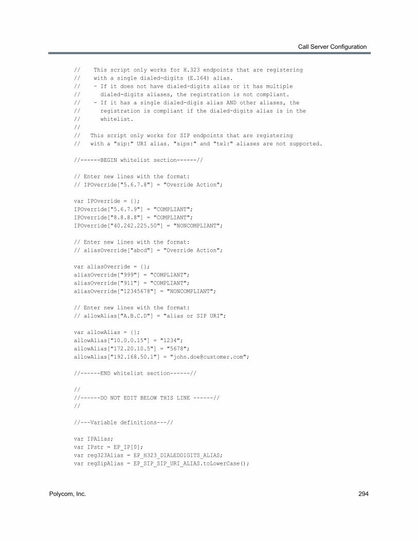
Call Server Configuration
Polycom, Inc. 294
// This script only works for H.323 endpoints that are registering// with a single dialed-digits (E.164) alias.// - If it does not have dialed-digits alias or it has multiple// dialed-digits aliases, the registration is not compliant.// - If it has a single dialed-digis alias AND other aliases, the // registration is compliant if the dialed-digits alias is in the// whitelist.//// This script only works for SIP endpoints that are registering// with a "sip:" URI alias. "sips:" and "tel:" aliases are not supported.
//------BEGIN whitelist section------//
// Enter new lines with the format:// IPOverride["5.6.7.8"] = "Override Action";
var IPOverride = {};IPOverride["5.6.7.9"] = "COMPLIANT";IPOverride["8.8.8.8"] = "COMPLIANT";IPOverride["40.242.225.50"] = "NONCOMPLIANT";
// Enter new lines with the format:// aliasOverride["abcd"] = "Override Action";
var aliasOverride = {};aliasOverride["999"] = "COMPLIANT";aliasOverride["911"] = "COMPLIANT";aliasOverride["12345678"] = "NONCOMPLIANT";
// Enter new lines with the format:// allowAlias["A.B.C.D"] = "alias or SIP URI";
var allowAlias = {};allowAlias["10.0.0.15"] = "1234";allowAlias["172.20.10.5"] = "5678";allowAlias["192.168.50.1"] = "[email protected]";
//------END whitelist section------//
////------DO NOT EDIT BELOW THIS LINE ------////
//---Variable definitions---//
var IPAlias;var IPstr = EP_IP[0];var reg323Alias = EP_H323_DIALEDDIGITS_ALIAS;var regSipAlias = EP_SIP_SIP_URI_ALIAS.toLowerCase();
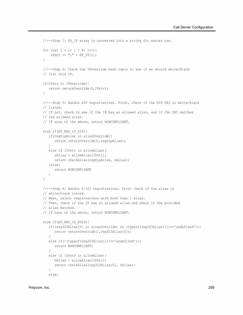
Call Server Configuration
Polycom, Inc. 295
//---Step 1: EP_IP array is converted into a string for easier use.
for (var i = 1; i < 4; i++){ IPstr += "." + EP_IP[i];}
//---Step 2: Check the IPOverride hash table to see if we should white/black// list this IP.
if(IPstr in IPOverride){ return returnOverride(0,IPstr);}
//---Step 3: Handle SIP registrations. First, check if the SIP URI is white/black// listed. // If not, check to see if the IP has an allowed alias, and if the URI matches// the allowed alias. // If none of the above, return NONCOMPLIANT.
else if(EP_REG_IS_SIP){ if(regSipAlias in aliasOverride){ return returnOverride(1,regSipAlias); } else if (IPstr in allowAlias){ sAlias = allowAlias[IPstr]; return checkAlias(regSipAlias, sAlias); }else{ return NONCOMPLIANT }}
//---Step 4: Handle H.323 registrations. First check if the alias is // white/black listed. // Next, reject registrations with more than 1 alias. // Then, check if the IP has an allowed alias and check if the provided // alias matches. // If none of the above, return NONCOMPLIANT.
else if(EP_REG_IS_H323){ if((reg323Alias[0] in aliasOverride) && (typeof(reg323Alias[1])=='undefined')){ return returnOverride(1,reg323Alias[0]); } else if(!(typeof(reg323Alias[1])=='undefined')){ return NONCOMPLIANT; } else if (IPstr in allowAlias){ hAlias = allowAlias[IPstr]; return checkAlias(reg323Alias[0], hAlias); } else{
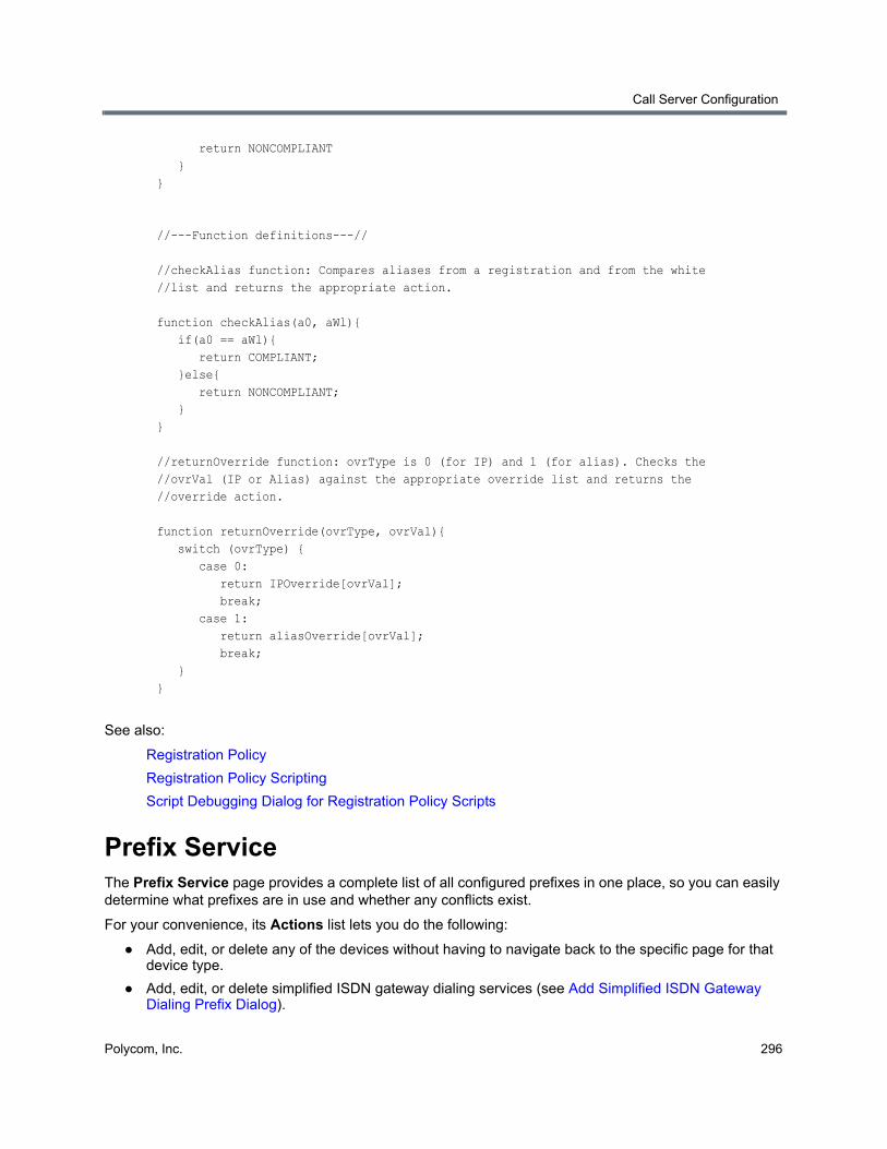
Call Server Configuration
Polycom, Inc. 296
return NONCOMPLIANT }}
//---Function definitions---//
//checkAlias function: Compares aliases from a registration and from the white //list and returns the appropriate action.
function checkAlias(a0, aWl){ if(a0 == aWl){ return COMPLIANT; }else{ return NONCOMPLIANT; }}
//returnOverride function: ovrType is 0 (for IP) and 1 (for alias). Checks the //ovrVal (IP or Alias) against the appropriate override list and returns the //override action.
function returnOverride(ovrType, ovrVal){ switch (ovrType) { case 0: return IPOverride[ovrVal]; break; case 1: return aliasOverride[ovrVal]; break; }}
See also:
Registration Policy
Registration Policy Scripting
Script Debugging Dialog for Registration Policy Scripts
Prefix ServiceThe Prefix Service page provides a complete list of all configured prefixes in one place, so you can easily determine what prefixes are in use and whether any conflicts exist.
For your convenience, its Actions list lets you do the following:
● Add, edit, or delete any of the devices without having to navigate back to the specific page for that device type.
● Add, edit, or delete simplified ISDN gateway dialing services (see Add Simplified ISDN Gateway Dialing Prefix Dialog).
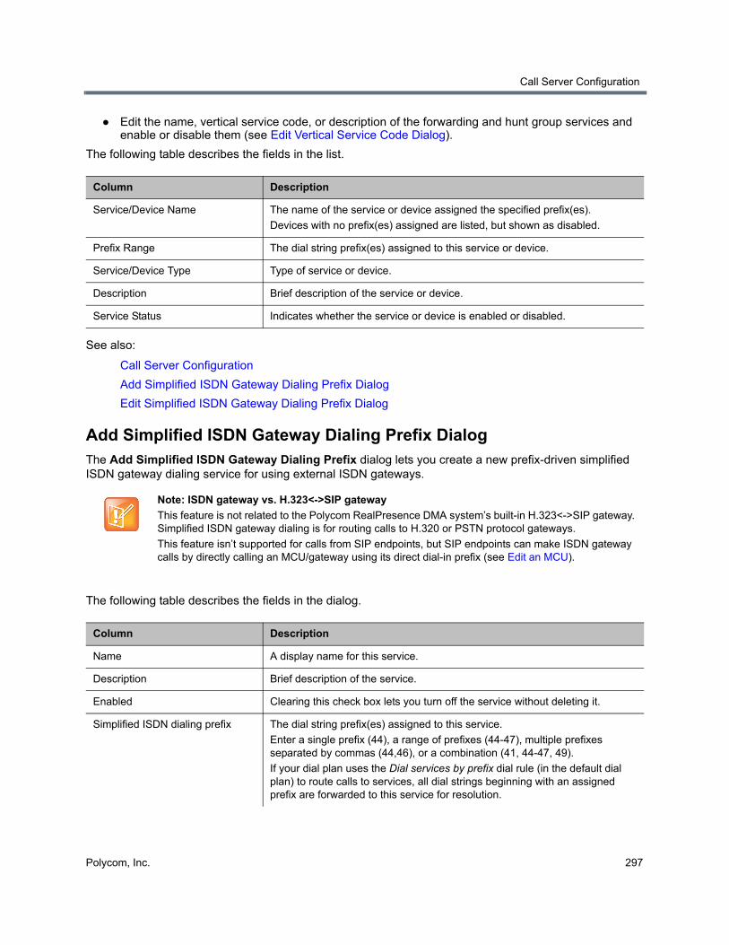
Call Server Configuration
Polycom, Inc. 297
● Edit the name, vertical service code, or description of the forwarding and hunt group services and enable or disable them (see Edit Vertical Service Code Dialog).
The following table describes the fields in the list.
See also:
Call Server Configuration
Add Simplified ISDN Gateway Dialing Prefix Dialog
Edit Simplified ISDN Gateway Dialing Prefix Dialog
Add Simplified ISDN Gateway Dialing Prefix DialogThe Add Simplified ISDN Gateway Dialing Prefix dialog lets you create a new prefix-driven simplified ISDN gateway dialing service for using external ISDN gateways.
The following table describes the fields in the dialog.
Column Description
Service/Device Name The name of the service or device assigned the specified prefix(es).
Devices with no prefix(es) assigned are listed, but shown as disabled.
Prefix Range The dial string prefix(es) assigned to this service or device.
Service/Device Type Type of service or device.
Description Brief description of the service or device.
Service Status Indicates whether the service or device is enabled or disabled.
Note: ISDN gateway vs. H.323<->SIP gateway
This feature is not related to the Polycom RealPresence DMA system’s built-in H.323<->SIP gateway. Simplified ISDN gateway dialing is for routing calls to H.320 or PSTN protocol gateways.
This feature isn’t supported for calls from SIP endpoints, but SIP endpoints can make ISDN gateway calls by directly calling an MCU/gateway using its direct dial-in prefix (see Edit an MCU).
Column Description
Name A display name for this service.
Description Brief description of the service.
Enabled Clearing this check box lets you turn off the service without deleting it.
Simplified ISDN dialing prefix The dial string prefix(es) assigned to this service.
Enter a single prefix (44), a range of prefixes (44-47), multiple prefixes separated by commas (44,46), or a combination (41, 44-47, 49).
If your dial plan uses the Dial services by prefix dial rule (in the default dial plan) to route calls to services, all dial strings beginning with an assigned prefix are forwarded to this service for resolution.

Call Server Configuration
Polycom, Inc. 298
See also:
Call Server Configuration
Prefix Service
Edit Simplified ISDN Gateway Dialing Prefix DialogThe Edit Simplified ISDN Gateway Dialing Prefix dialog lets you edit a prefix-driven simplified ISDN gateway dialing service.
The following table describes the fields in the dialog.
Use all ISDN gateways Indicates whether this service applies to all available gateways or only those selected below.
Available ISDN gateways Lists the ISDN gateways that have at least one session profile specifying an H.320 or PSTN protocol. See Edit an MCU.
Selected ISDN gateways Lists the selected ISDN gateways. The arrow buttons move gateways from one list to the other.
Note: ISDN gateway vs. H.323<->SIP gateway
This feature is not related to the Polycom RealPresence DMA system’s built-in H.323<->SIP gateway. Simplified ISDN gateway dialing is for routing calls to H.320 or PSTN protocol gateways.
This feature isn’t supported for calls from SIP endpoints, but SIP endpoints can make ISDN gateway calls by directly calling an MCU/gateway using its direct dial-in prefix (see Edit an MCU).
Column Description
Name A display name for this service.
Description Brief description of the service.
Enabled Clearing this check box lets you turn off the service without deleting it.
Simplified ISDN dialing prefix The dial string prefix(es) assigned to this service.
Enter a single prefix (44), a range of prefixes (44-47), multiple prefixes separated by commas (44,46), or a combination (41, 44-47, 49).
If your dial plan uses the Dial services by prefix dial rule (in the default dial plan) to route calls to services, all dial strings beginning with an assigned prefix are forwarded to this service for resolution.
Use all ISDN gateways Indicates whether this service applies to all available gateways or only those selected below.
Available ISDN gateways Lists the gateways that have at least one session profile specifying an H.320 or PSTN protocol. See Edit an MCU.
Selected ISDN gateways Lists the selected gateways. The arrow buttons move gateways from one list to the other.
Column Description
Call Server Configuration
Polycom, Inc. 299
See also:
Call Server Configuration
Prefix Service
Edit Vertical Service Code DialogThe Edit Vertical Service Code dialog lets you edit a call forwarding or hunt group service invoked when callers dial the vertical service code (VSC) for that service followed by the alias. These services are included on the Prefix Service page and can’t be deleted. But you can disable them or change their names, descriptions, or VSCs (shown in the Prefix Range column of the Prefix Service page). If you change the VSCs, be sure to inform users of the change.
The following table describes the fields in the dialog.
See also:
Call Server Configuration
Prefix Service
Embedded DNSIn a superclustered configuration, the clusters that make up the supercluster automatically take over for each other in the event of an outage. In order to gain the full benefit of this feature, however, the endpoints that are registered to each cluster must re-register to a new cluster when the new cluster takes over.
This can be accomplished by specifying the gatekeeper or SIP proxy that each endpoint will register to as a site’s domain name, rather than an IP address. Then, when there is a failover, the DNS A record for that site’s domain name can be mapped to a different IP address, changing the Call Server that each endpoint is registered to.
The embedded DNS capability of the Polycom RealPresence DMA system automates this procedure.
Each Polycom RealPresence DMA server hosts its own embedded DNS server. It publishes a DNS CNAME record for each site. That CNAME record maps to the active cluster with which endpoints at the site should register. Whenever responsibility for the site moves from one cluster to another, the change is automatically published by the embedded DNS server. Endpoints will automatically re-register to the correct cluster.
Column Description
Type The type of service. Display only.
Name A display name for this service.
Code The vertical service code (VSC) for this service. Must consist of an asterisk/star (*) followed by two digits.
Registered endpoints can activate this feature by dialing the VSC followed by the alias. They can deactivate it by dialing the VSC alone.
Description Brief description of the service.
Enabled Clearing this check box lets you turn off the service.
Call Server Configuration
Polycom, Inc. 300
You can enable these embedded DNS servers on the Embedded DNS page. This is a supercluster-wide setting.
Embedded DNS is enabled by default for newly installed RealPresence DMA systems. In its default configuration, the Call server sub-domain controlled by DMA system field is populated with the default sub-domain video.local. The system acts as an initial DNS server, resolving the FQDN dma.video.local to the virtual IPv4 address of the local cluster. If you change the sub-domain to a custom value, the embedded DNS service resolves dma.<newsubdomain> to the IP address of the cluster.
If you wish to use this feature, your enterprise DNS must place the Polycom RealPresence DMA supercluster in charge of resolving the sub-domain specified on this page. To do this, you must:
● Add NS records to your enterprise DNS so that it refers requests to resolve the site-based logical host name (see Site Information Dialog) to these embedded DNS servers.
● Configure your enterprise DNS to forward requests for names in the site-based logical host name to any of the clusters in the supercluster.
For more information, see Add Required DNS Records for the Polycom RealPresence DMA System.
The following table describes the fields on the Embedded DNS page.
To enable DNS publishing
1 Be sure you’ve added the required NS records, one for each cluster in the supercluster, to your enterprise DNS and have configured it to forward requests for names in the logical Call Server domain to any of the clusters in the supercluster (see Additional DNS Records for the Optional Embedded DNS Feature).
2 Go to Admin > Call Server > Embedded DNS.
3 Click Enable embedded DNS service.
4 In the Call server sub-domain controlled by RealPresence DMA field, enter the logical Call Server domain name (the enterprise domain for which the RealPresence DMA system is to provide DNS) and click Update.
Note: Embedded DNS server does not support IPv6
The embedded DNS functionality is not supported in an IPv6 environment.
Field Description
Enable embedded DNS service Enables the embedded DNS servers.
Call server sub-domain controlled by RealPresence DMA
The fully qualified domain name of the enterprise domain for which the RealPresence DMA system is to provide DNS. For instance, for the base domain example.com, the sub-domain that the RealPresence DMA system services might be:
callservers.example.com
This is the logical Call Server domain name for which you must create NS records in your enterprise DNS. And this is the domain name that the system combines with each site name to form the logical FQDN that endpoints in each site should register to.
Call Server Configuration
Polycom, Inc. 301
5 Reconfigure your endpoints to register to the correct domain name for their site.
To determine the correct domain name for a site, go to Network > Site Topology > Sites, select the site, and click Site Information. The Logical host name field displays the correct domain name. It takes the form:
callserver-<site name>.<logical Call Server domain name>
For instance, if the fully qualified domain name for the logical Call Server domain is callservers.example.com, the correct domain name for endpoints in the paris site is:
callserver-paris.callservers.example.com
See also:
Call Server Configuration
History Retention SettingsThe Polycom RealPresence DMA system is pre-configured with the number of history records of various types to retain. When the retention limit for a record type is reached, the system purges a specific number of the oldest records of that type.
The following table shows the retention limit for each record type and how many are purged at a time when the retention limit is reached. The values specified are for each cluster, not the total for the entire supercluster.
Contact Polycom Global Services if you want to discuss the possibility of changing the retention limits.
The History Retention Settings page lets you specify whether to retain registration history records, and if so, whether to include registration keep-alive messages. You can also specify how many repeated low-value signaling records to retain. The following table describes the fields on the page. Only users with the Auditor role can access this page.
Note: Verify RealPresence Resource Manager system settings
If you have a Polycom RealPresence Resource Manager system integrated with the RealPresence DMA system, make sure that in its Edit DMA dialog, Support DMA Supercluster is selected.
Enter all network/DNS-related information in all lower case to avoid possible case-sensitivity issues with various devices and ensure interoperability.
Record Type Retention Limit Number of Records Purged When Limit Is Reached
Registration history 505,000 5,000
Registration signaling 2,000,000 20,000
Call history 505,000 5,000
Call signaling history 12,625,000 125,000
Conference history 202,000 2,000
CDR export history 11,000 1,000
Call Server Configuration
Polycom, Inc. 302
The settings on this page are supercluster-wide (the clusters aren’t independently configured).
To configure history record retention
1 Log into the system as a user with the Auditor role and go to Admin > Call Server > History Retention Settings.
2 Specify whether to record registration history, and if so, whether to include keep-alive messages.
3 Specify how many low-value signaling records to retain.
4 Click Update.
A dialog informs you that the configuration has been updated.
5 Click OK.
See also:
Call Server Configuration
Field Description
Enable recording of registration history
Enables the system to retain Call Server registration records (see Registration History Report).
Include keep-alive messages in registration history
If selected, the Call Server history includes the keep-alive messages sent by registered endpoints and the Call Server’s responses.
Selecting this option significantly increases the number of Call Server registration records per period of time.
Number of repeated low-value signaling event records to retain
The number of less-important signaling messages (such as INFO messages about in-call status) to retain for a given call (from 0 to 10; default is 3).
Once the limit is reached, subsequent messages of that type are processed, but not recorded in the call signaling history.
Polycom, Inc. 303
Site Topology
This section describes the following Polycom® RealPresence® Distributed Media Application™ (DMA®) 7000 site topology configuration topics:
● About Site Topology
● Sites
● Site Links
● Site-to-Site Exclusions
● Territories
● Network Clouds
● Bandwidth Management
● Site Topology Configuration Procedures
About Site TopologySite topology information logically describes your network and its interfaces to other networks, including the following elements:
● Site — A local area network (LAN) that generally corresponds with a geographic location such as an office or plant. A site contains one or more network subnets, so a device’s IP address identifies the site to which it belongs.
● Network cloud — A Multiprotocol Label Switching (MPLS) network cloud defined in the site topology. An MPLS network is a private network that links multiple locations and uses label switching to tag packets with origin, destination, and quality of service (QOS) information.
● Site link — A network connection between two sites or between a site and an MPLS network cloud.
● Site-to-site exclusion — A site-to-site connection that the site topology doesn’t permit a voice or video call to use.
● Territory — A collection of one or more sites for which a Polycom RealPresence DMA cluster is responsible. Territories serve multiple purposes in a Polycom RealPresence DMA system deployment. See Territories.
A freshly installed RealPresence DMA system provides a default site topology with sites, subnets, and a site link that allow for endpoint registration and call routing (both multipoint and point-to-point).
Note: Network topology and site topology can differ
Site topology information provides a logical model representation of a network topology, not necessarily a fully accurate literal representation of a full network.
Site Topology
Polycom, Inc. 304
The RealPresence DMA system uses site topology information for a variety of purposes, including cascade for bandwidth conferences, bandwidth management, Session Border Controller selection, and cluster responsibility management in a supercluster. It can get it in one of two ways:
● If you have a Polycom RealPresence Resource Manager system, integrate the Polycom RealPresence DMA system with it (see RealPresence Resource Manager Integration) to automatically get its site topology information.
● If you don’t have a Polycom RealPresence Resource Manager system, enter site topology information about your network directly into the Polycom RealPresence DMA system’s site topology pages.
If your RealPresence DMA system is superclustered (see About Superclustering), site topology data only needs to be created (or obtained from a RealPresence Resource Manager system) on one cluster of the supercluster. It’s replicated across the supercluster.
For a conference with cascading for bandwidth enabled, the RealPresence DMA system uses the site topology information to route calls to the nearest eligible MCU (based on pools and pool orders) that has available capacity and to create the cascade links between MCUs.
Bandwidth Management Once you model a site topology to represent your physical network, you can use it to manage bandwidth between your sites, preventing conference traffic from saturating the network.
Before the RealPresence DMA system routes a call, it considers the source and destination IP addresses in the site topology and determines a media path from the source subnet to the destination subnet, taking into account the existing calls and bandwidth restrictions along that path. If sites or site links have bandwidth restrictions, the system reduces the call rate of the call at the time of call setup so that it meets those restrictions, if possible. If the media path is already saturated with other conference traffic, the RealPresence DMA system rejects the call attempt.
Note: Integration not supported in maximum security mode
Integration with a Polycom RealPresence Resource Manager system is not supported in Maximum security mode.
Note: MCU Cascading considerations
Cascading for bandwidth uses a hub-and-spoke configuration so that each cascaded MCU is only one link away from the “hub” MCU, which hosts the conference. The conference is hosted on the same MCU that would have been chosen in the absence of cascading, using the pool order applicable to the conference. See MCU Pool Orders.
The cascade links between MCUs must use H.323 signaling. For conferences with cascading enabled, the Polycom RealPresence DMA system selects only MCUs that have H.323 signaling enabled.
This cascade link requirement doesn’t affect endpoints, which may dial in using SIP (assuming the MCUs and the Polycom RealPresence DMA system are also configured for SIP signaling).
Site Topology
Polycom, Inc. 305
See also:
Site Links
Site-to-Site Exclusions
Territories
Network Clouds
Site Topology Configuration Procedures
SitesThe Sites page contains a list of the sites defined in the site topology.
If the system is integrated with a Polycom RealPresence Resource Manager system, it receives this information from that system, and this page is read-only. If not, you can enter site information.
The Internet/VPN and Default Site entries are provided with a fresh installation of the RealPresence DMA system.
The Internet/VPN entry always exists and can’t be edited or deleted. It can’t be assigned to a territory or controlled by a cluster. Endpoints whose subnet isn’t in any defined site in the enterprise network are considered to be in the Internet/VPN site. They can register to a cluster only if site-less registrations are allowed (see Registration Policy).
The Default Site entry has no restrictions. This site is configured to route SIP calls through a SIP-aware firewall, and includes 3 subnets that together cover the private IPv4 address space.
The protocol-specific routing settings for a site determine whether and how calls from that site can traverse the firewall to reach endpoints outside the enterprise network:
● Via a transparent firewall
● Via the specified SBC
● Not at all
The site’s routing settings are used when the dial string is resolved by a dial rule using the Resolve to external address or Resolve to IP address action (rules 5 and 6, respectively, of the default dial plan; see Dial Rules).
The commands in the Actions list let you add a site, edit or delete sites (other than Internet/VPN), and see information about a site, including the number of devices of each type it contains.
The following table describes the fields in the list.
Note: Consider adding an SBC or SIP peer
Alternatively, you can add an H.323 SBC (see External H.323 SBC) or a SIP peer (see External SIP Peer) that can only be reached by dialing a specific prefix or prefixes. A dial string beginning with such a prefix can be resolved by the dial rule using the Resolve to service prefix action (rule 4 of the default dial plan).
Note: Avoid case-sensitivity issues when entering network configuration
Enter all network/DNS-related information in all lower case to avoid possible case-sensitivity issues with various devices and ensure interoperability.
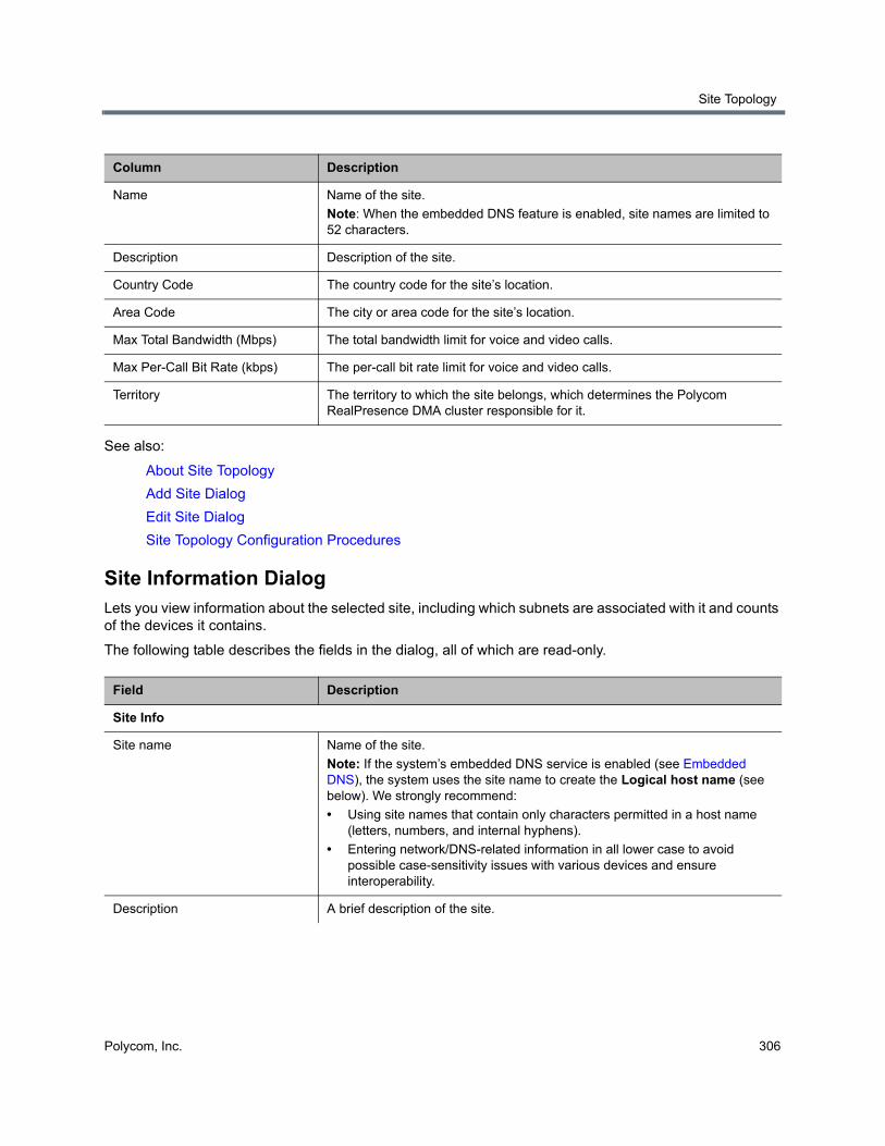
Site Topology
Polycom, Inc. 306
See also:
About Site Topology
Add Site Dialog
Edit Site Dialog
Site Topology Configuration Procedures
Site Information DialogLets you view information about the selected site, including which subnets are associated with it and counts of the devices it contains.
The following table describes the fields in the dialog, all of which are read-only.
Column Description
Name Name of the site.
Note: When the embedded DNS feature is enabled, site names are limited to 52 characters.
Description Description of the site.
Country Code The country code for the site’s location.
Area Code The city or area code for the site’s location.
Max Total Bandwidth (Mbps) The total bandwidth limit for voice and video calls.
Max Per-Call Bit Rate (kbps) The per-call bit rate limit for voice and video calls.
Territory The territory to which the site belongs, which determines the Polycom RealPresence DMA cluster responsible for it.
Field Description
Site Info
Site name Name of the site.
Note: If the system’s embedded DNS service is enabled (see Embedded DNS), the system uses the site name to create the Logical host name (see below). We strongly recommend:
• Using site names that contain only characters permitted in a host name (letters, numbers, and internal hyphens).
• Entering network/DNS-related information in all lower case to avoid possible case-sensitivity issues with various devices and ensure interoperability.
Description A brief description of the site.
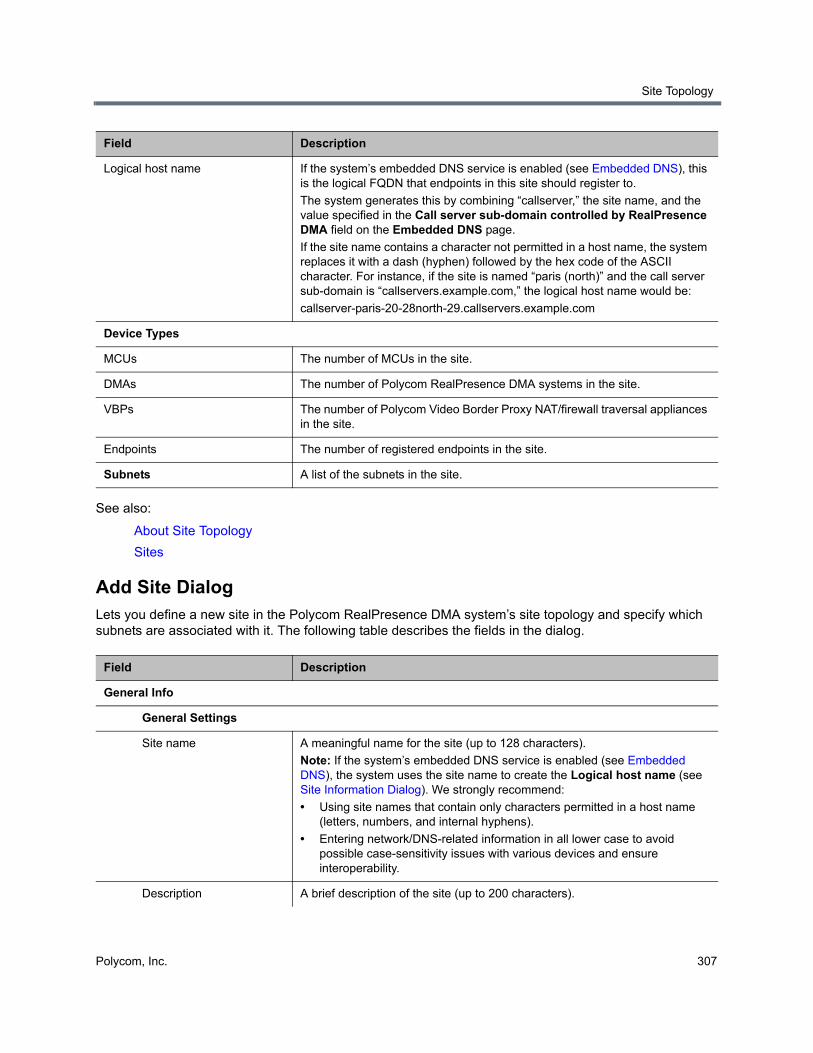
Site Topology
Polycom, Inc. 307
See also:
About Site Topology
Sites
Add Site DialogLets you define a new site in the Polycom RealPresence DMA system’s site topology and specify which subnets are associated with it. The following table describes the fields in the dialog.
Logical host name If the system’s embedded DNS service is enabled (see Embedded DNS), this is the logical FQDN that endpoints in this site should register to.
The system generates this by combining “callserver,” the site name, and the value specified in the Call server sub-domain controlled by RealPresence DMA field on the Embedded DNS page.
If the site name contains a character not permitted in a host name, the system replaces it with a dash (hyphen) followed by the hex code of the ASCII character. For instance, if the site is named “paris (north)” and the call server sub-domain is “callservers.example.com,” the logical host name would be:
callserver-paris-20-28north-29.callservers.example.com
Device Types
MCUs The number of MCUs in the site.
DMAs The number of Polycom RealPresence DMA systems in the site.
VBPs The number of Polycom Video Border Proxy NAT/firewall traversal appliances in the site.
Endpoints The number of registered endpoints in the site.
Subnets A list of the subnets in the site.
Field Description
General Info
General Settings
Site name A meaningful name for the site (up to 128 characters).
Note: If the system’s embedded DNS service is enabled (see Embedded DNS), the system uses the site name to create the Logical host name (see Site Information Dialog). We strongly recommend:
• Using site names that contain only characters permitted in a host name (letters, numbers, and internal hyphens).
• Entering network/DNS-related information in all lower case to avoid possible case-sensitivity issues with various devices and ensure interoperability.
Description A brief description of the site (up to 200 characters).
Field Description
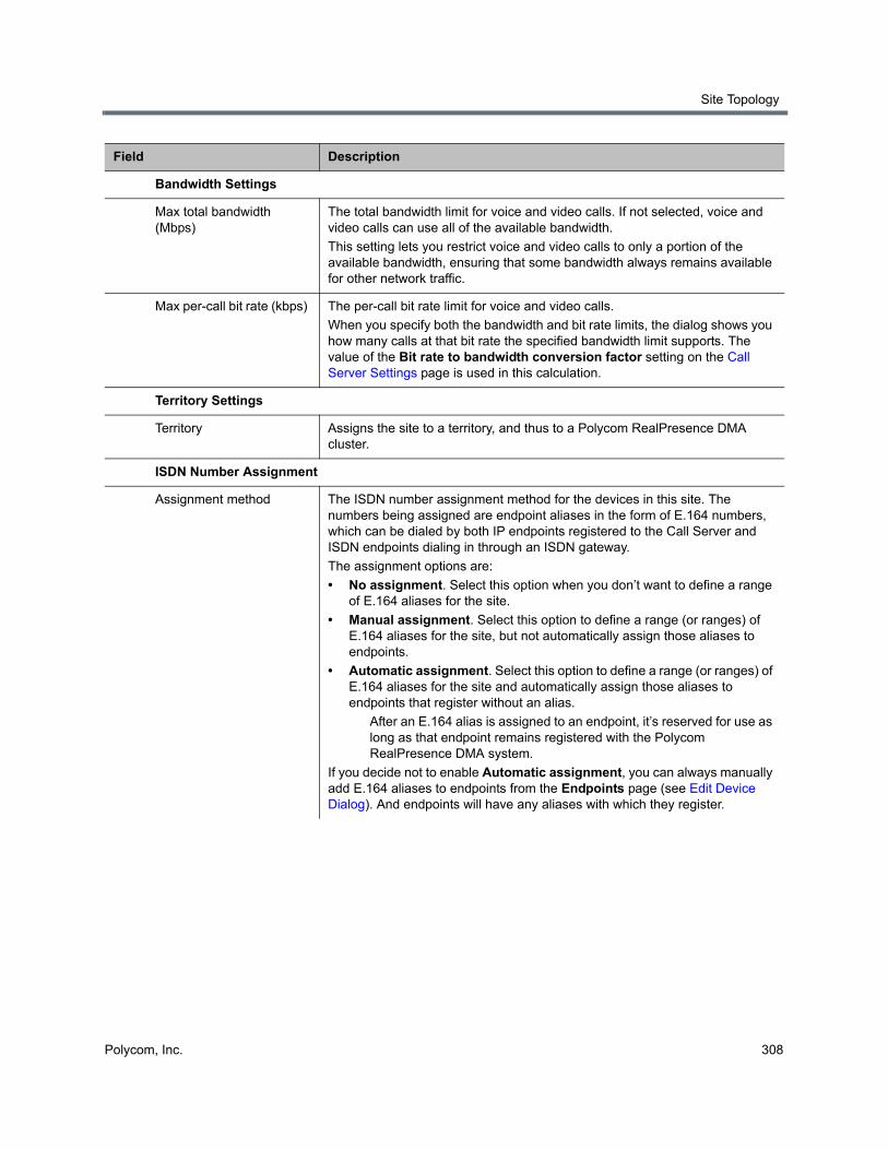
Site Topology
Polycom, Inc. 308
Bandwidth Settings
Max total bandwidth (Mbps)
The total bandwidth limit for voice and video calls. If not selected, voice and video calls can use all of the available bandwidth.
This setting lets you restrict voice and video calls to only a portion of the available bandwidth, ensuring that some bandwidth always remains available for other network traffic.
Max per-call bit rate (kbps) The per-call bit rate limit for voice and video calls.
When you specify both the bandwidth and bit rate limits, the dialog shows you how many calls at that bit rate the specified bandwidth limit supports. The value of the Bit rate to bandwidth conversion factor setting on the Call Server Settings page is used in this calculation.
Territory Settings
Territory Assigns the site to a territory, and thus to a Polycom RealPresence DMA cluster.
ISDN Number Assignment
Assignment method The ISDN number assignment method for the devices in this site. The numbers being assigned are endpoint aliases in the form of E.164 numbers, which can be dialed by both IP endpoints registered to the Call Server and ISDN endpoints dialing in through an ISDN gateway.
The assignment options are:
• No assignment. Select this option when you don’t want to define a range of E.164 aliases for the site.
• Manual assignment. Select this option to define a range (or ranges) of E.164 aliases for the site, but not automatically assign those aliases to endpoints.
• Automatic assignment. Select this option to define a range (or ranges) of E.164 aliases for the site and automatically assign those aliases to endpoints that register without an alias.
After an E.164 alias is assigned to an endpoint, it’s reserved for use as long as that endpoint remains registered with the Polycom RealPresence DMA system.
If you decide not to enable Automatic assignment, you can always manually add E.164 aliases to endpoints from the Endpoints page (see Edit Device Dialog). And endpoints will have any aliases with which they register.
Field Description
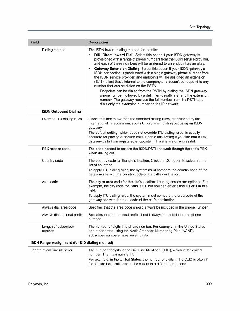
Site Topology
Polycom, Inc. 309
Dialing method The ISDN inward dialing method for the site:
• DID (Direct Inward Dial). Select this option if your ISDN gateway is provisioned with a range of phone numbers from the ISDN service provider, and each of these numbers will be assigned to an endpoint as an alias.
• Gateway Extension Dialing. Select this option if your ISDN gateway’s ISDN connection is provisioned with a single gateway phone number from the ISDN service provider, and endpoints will be assigned an extension (E.164 alias) that’s internal to the company and doesn’t correspond to any number that can be dialed on the PSTN.
Endpoints can be dialed from the PSTN by dialing the ISDN gateway phone number, followed by a delimiter (usually a #) and the extension number. The gateway receives the full number from the PSTN and dials only the extension number on the IP network.
ISDN Outbound Dialing
Override ITU dialing rules Check this box to override the standard dialing rules, established by the International Telecommunications Union, when dialing out using an ISDN gateway.
The default setting, which does not override ITU dialing rules, is usually accurate for placing outbound calls. Enable this setting if you find that ISDN gateway calls from registered endpoints in this site are unsuccessful.
PBX access code The code needed to access the ISDN/PSTN network through the site’s PBX when dialing out.
Country code The country code for the site’s location. Click the CC button to select from a list of countries.
To apply ITU dialing rules, the system must compare the country code of the gateway site with the country code of the call’s destination.
Area code The city or area code for the site’s location. Leading zeroes are optional. For example, the city code for Paris is 01, but you can enter either 01 or 1 in this field.
To apply ITU dialing rules, the system must compare the area code of the gateway site with the area code of the call’s destination.
Always dial area code Specifies that the area code should always be included in the phone number.
Always dial national prefix Specifies that the national prefix should always be included in the phone number.
Length of subscriber number
The number of digits in a phone number. For example, in the United States and other areas using the North American Numbering Plan (NANP), subscriber numbers have seven digits.
ISDN Range Assignment (for DID dialing method)
Length of call line identifier The number of digits in the Call Line Identifier (CLID), which is the dialed number. The maximum is 17.
For example, in the United States, the number of digits in the CLID is often 7 for outside local calls and 11 for callers in a different area code.
Field Description

Site Topology
Polycom, Inc. 310
Length of short phone number The number of digits in the short form of the dialing number.
For example, in the United States, internal extensions are usually four or five digits.
ISDN Number Ranges The number ranges available for assignment to endpoints in the site.
Click Add to add a new range of numbers. Click Edit or Delete to change or delete the selected range.
The start and end numbers in the range should be entered with the same number of digits. If the range is 303-223-1000 to 1999, enter 3032231000 and 3032231999.
ISDN Range Assignment (for gateway extension dialing method)
ISDN gateway number An ISDN gateway phone number for the site. This field is just for your reference. It’s not used by the software to process calls.
If the site has more than one ISDN gateway, you’ll need to know their access numbers and determine how to instruct inbound users to call.
E.164 start The beginning of the range of E.164 extensions associated with the site.
E.164 end The end of the range of E.164 extensions associated with the site.
The start and end numbers in the range should be entered with the same number of digits.
H.323 Routing
Internet calls are not allowed Disables H.323 calls to the internet.
Allowed via H.323-aware firewall Allows H.323 calls to the internet through a firewall.
Allowed via H.323-aware SBC or ALG
Enables H.323 calls to the internet through the specified session border controller (SBC) or application layer gateway (ALG).
Call signaling address (IPv4) The call signaling address for the H.323 SBC or ALG.
Port The call signaling port for the H.323 SBC or ALG.
SIP Routing
Internet calls are not allowed Disables SIP calls to the internet.
Allowed via SIP-aware firewall Enables calls to the internet through a firewall.
Allowed via SIP-aware SBC or ALG
Enables SIP calls to the internet through the specified session border controller (SBC) or application layer gateway (ALG).
Call signaling address (IPv4) The call signaling address for the SBC or ALG.
Port The call signaling port for the SBC or ALG.
Subnets Lists the subnets in the site. Click Add to add a subnet. Select a subnet in the table and click Edit or Delete to modify or remove it.
Subnet Name The unique name of the subnet.
Field Description
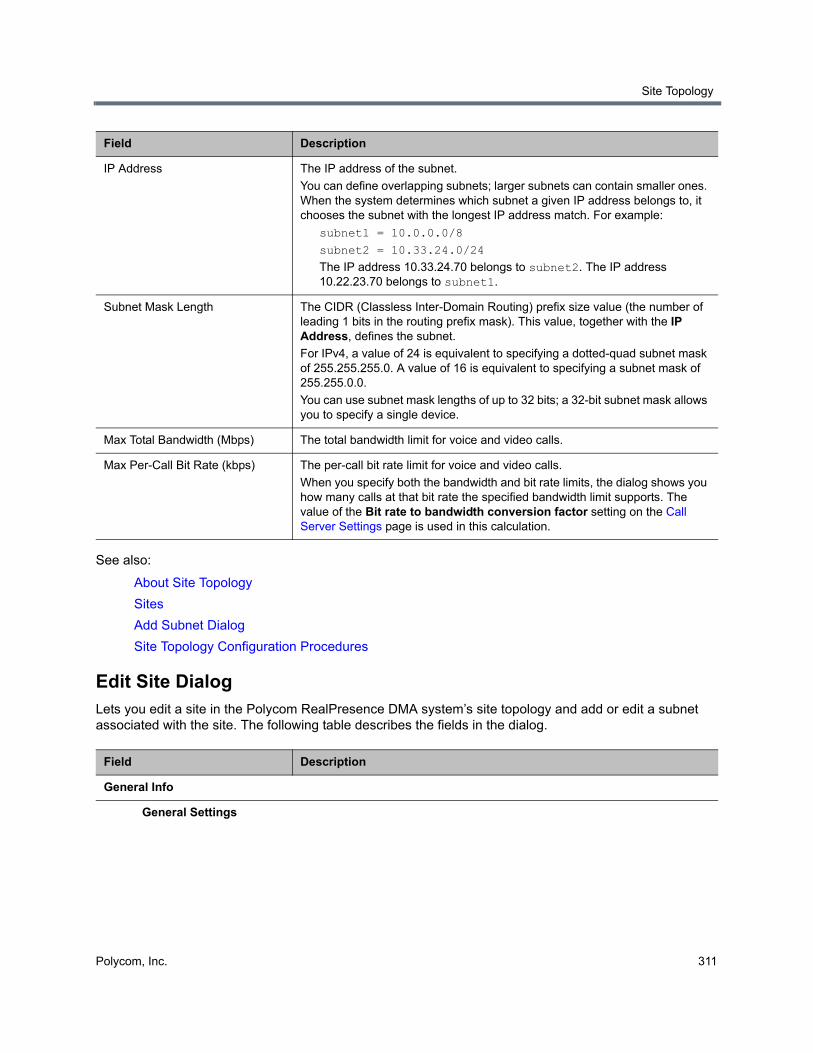
Site Topology
Polycom, Inc. 311
See also:
About Site Topology
Sites
Add Subnet Dialog
Site Topology Configuration Procedures
Edit Site DialogLets you edit a site in the Polycom RealPresence DMA system’s site topology and add or edit a subnet associated with the site. The following table describes the fields in the dialog.
IP Address The IP address of the subnet.
You can define overlapping subnets; larger subnets can contain smaller ones. When the system determines which subnet a given IP address belongs to, it chooses the subnet with the longest IP address match. For example:
subnet1 = 10.0.0.0/8
subnet2 = 10.33.24.0/24
The IP address 10.33.24.70 belongs to subnet2. The IP address 10.22.23.70 belongs to subnet1.
Subnet Mask Length The CIDR (Classless Inter-Domain Routing) prefix size value (the number of leading 1 bits in the routing prefix mask). This value, together with the IP Address, defines the subnet.
For IPv4, a value of 24 is equivalent to specifying a dotted-quad subnet mask of 255.255.255.0. A value of 16 is equivalent to specifying a subnet mask of 255.255.0.0.
You can use subnet mask lengths of up to 32 bits; a 32-bit subnet mask allows you to specify a single device.
Max Total Bandwidth (Mbps) The total bandwidth limit for voice and video calls.
Max Per-Call Bit Rate (kbps) The per-call bit rate limit for voice and video calls.
When you specify both the bandwidth and bit rate limits, the dialog shows you how many calls at that bit rate the specified bandwidth limit supports. The value of the Bit rate to bandwidth conversion factor setting on the Call Server Settings page is used in this calculation.
Field Description
General Info
General Settings
Field Description
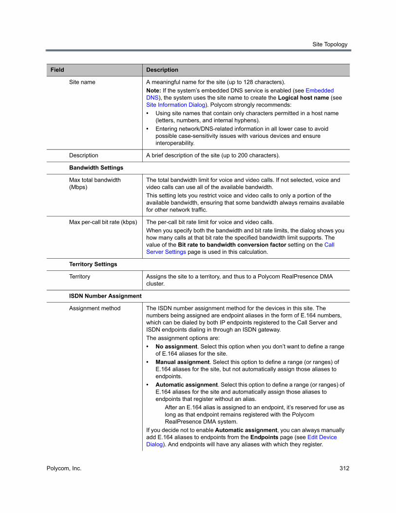
Site Topology
Polycom, Inc. 312
Site name A meaningful name for the site (up to 128 characters).
Note: If the system’s embedded DNS service is enabled (see Embedded DNS), the system uses the site name to create the Logical host name (see Site Information Dialog). Polycom strongly recommends:
• Using site names that contain only characters permitted in a host name (letters, numbers, and internal hyphens).
• Entering network/DNS-related information in all lower case to avoid possible case-sensitivity issues with various devices and ensure interoperability.
Description A brief description of the site (up to 200 characters).
Bandwidth Settings
Max total bandwidth (Mbps)
The total bandwidth limit for voice and video calls. If not selected, voice and video calls can use all of the available bandwidth.
This setting lets you restrict voice and video calls to only a portion of the available bandwidth, ensuring that some bandwidth always remains available for other network traffic.
Max per-call bit rate (kbps) The per-call bit rate limit for voice and video calls.
When you specify both the bandwidth and bit rate limits, the dialog shows you how many calls at that bit rate the specified bandwidth limit supports. The value of the Bit rate to bandwidth conversion factor setting on the Call Server Settings page is used in this calculation.
Territory Settings
Territory Assigns the site to a territory, and thus to a Polycom RealPresence DMA cluster.
ISDN Number Assignment
Assignment method The ISDN number assignment method for the devices in this site. The numbers being assigned are endpoint aliases in the form of E.164 numbers, which can be dialed by both IP endpoints registered to the Call Server and ISDN endpoints dialing in through an ISDN gateway.
The assignment options are:
• No assignment. Select this option when you don’t want to define a range of E.164 aliases for the site.
• Manual assignment. Select this option to define a range (or ranges) of E.164 aliases for the site, but not automatically assign those aliases to endpoints.
• Automatic assignment. Select this option to define a range (or ranges) of E.164 aliases for the site and automatically assign those aliases to endpoints that register without an alias.
After an E.164 alias is assigned to an endpoint, it’s reserved for use as long as that endpoint remains registered with the Polycom RealPresence DMA system.
If you decide not to enable Automatic assignment, you can always manually add E.164 aliases to endpoints from the Endpoints page (see Edit Device Dialog). And endpoints will have any aliases with which they register.
Field Description

Site Topology
Polycom, Inc. 313
Dialing method The ISDN inward dialing method for the site:
• DID (Direct Inward Dial). Select this option if your ISDN gateway is provisioned with a range of phone numbers from the ISDN service provider, and each of these numbers will be assigned to an endpoint as an alias.
• Gateway Extension Dialing. Select this option if your ISDN gateway’s ISDN connection is provisioned with a single gateway phone number from the ISDN service provider, and endpoints will be assigned an extension (E.164 alias) that’s internal to the company and doesn’t correspond to any number that can be dialed on the PSTN.
Endpoints can be dialed from the PSTN by dialing the ISDN gateway phone number, followed by a delimiter (usually a #) and the extension number. The gateway receives the full number from the PSTN and dials only the extension number on the IP network.
ISDN Outbound Dialing
Override ITU dialing rules Select this check box to override the standard dialing rules, established by the International Telecommunications Union, when dialing out using an ISDN gateway.
The default setting, which does not override ITU dialing rules, is usually accurate for placing outbound calls. Enable this setting if you find that ISDN gateway calls from registered endpoints in this site are unsuccessful.
PBX access code The code needed to access the ISDN/PSTN network through the site’s PBX when dialing out.
Country code The country code for the site’s location. Click the CC button to select from a list of countries.
To apply ITU dialing rules, the system must compare the country code of the gateway site with the country code of the call’s destination.
Area code The city or area code for the site’s location. Leading zeroes are optional. For example, the city code for Paris is 01, but you can enter either 01 or 1 in this field.
To apply ITU dialing rules, the system must compare the area code of the gateway site with the area code of the call’s destination.
Always dial area code Specifies that the area code should always be included in the phone number.
Always dial national prefix Specifies that the national prefix should always be included in the phone number.
Length of subscriber number
The number of digits in a phone number. For example, in the United States and other areas using the North American Numbering Plan (NANP), subscriber numbers have seven digits.
ISDN Range Assignment (for DID dialing method)
Length of call line identifier The number of digits in the Call Line Identifier (CLID), which is the dialed number. The maximum is 17.
For example, in the United States, the number of digits in the CLID is often 7 for outside local calls and 11 for callers in a different area code.
Field Description
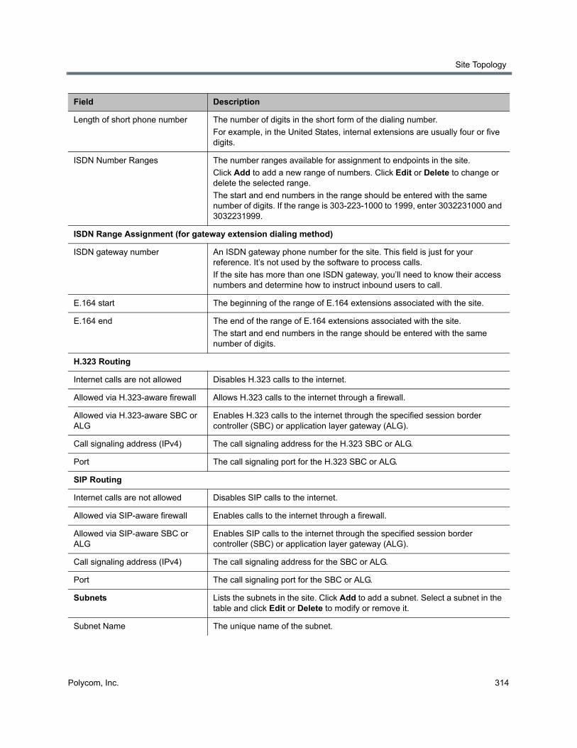
Site Topology
Polycom, Inc. 314
Length of short phone number The number of digits in the short form of the dialing number.
For example, in the United States, internal extensions are usually four or five digits.
ISDN Number Ranges The number ranges available for assignment to endpoints in the site.
Click Add to add a new range of numbers. Click Edit or Delete to change or delete the selected range.
The start and end numbers in the range should be entered with the same number of digits. If the range is 303-223-1000 to 1999, enter 3032231000 and 3032231999.
ISDN Range Assignment (for gateway extension dialing method)
ISDN gateway number An ISDN gateway phone number for the site. This field is just for your reference. It’s not used by the software to process calls.
If the site has more than one ISDN gateway, you’ll need to know their access numbers and determine how to instruct inbound users to call.
E.164 start The beginning of the range of E.164 extensions associated with the site.
E.164 end The end of the range of E.164 extensions associated with the site.
The start and end numbers in the range should be entered with the same number of digits.
H.323 Routing
Internet calls are not allowed Disables H.323 calls to the internet.
Allowed via H.323-aware firewall Allows H.323 calls to the internet through a firewall.
Allowed via H.323-aware SBC or ALG
Enables H.323 calls to the internet through the specified session border controller (SBC) or application layer gateway (ALG).
Call signaling address (IPv4) The call signaling address for the H.323 SBC or ALG.
Port The call signaling port for the H.323 SBC or ALG.
SIP Routing
Internet calls are not allowed Disables SIP calls to the internet.
Allowed via SIP-aware firewall Enables calls to the internet through a firewall.
Allowed via SIP-aware SBC or ALG
Enables SIP calls to the internet through the specified session border controller (SBC) or application layer gateway (ALG).
Call signaling address (IPv4) The call signaling address for the SBC or ALG.
Port The call signaling port for the SBC or ALG.
Subnets Lists the subnets in the site. Click Add to add a subnet. Select a subnet in the table and click Edit or Delete to modify or remove it.
Subnet Name The unique name of the subnet.
Field Description
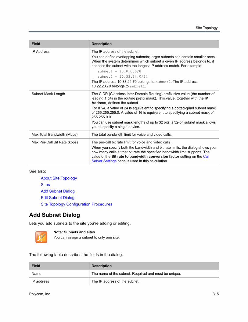
Site Topology
Polycom, Inc. 315
See also:
About Site Topology
Sites
Add Subnet Dialog
Edit Subnet Dialog
Site Topology Configuration Procedures
Add Subnet DialogLets you add subnets to the site you’re adding or editing.
The following table describes the fields in the dialog.
IP Address The IP address of the subnet.
You can define overlapping subnets; larger subnets can contain smaller ones. When the system determines which subnet a given IP address belongs to, it chooses the subnet with the longest IP address match. For example:
subnet1 = 10.0.0.0/8
subnet2 = 10.33.24.0/24
The IP address 10.33.24.70 belongs to subnet2. The IP address 10.22.23.70 belongs to subnet1.
Subnet Mask Length The CIDR (Classless Inter-Domain Routing) prefix size value (the number of leading 1 bits in the routing prefix mask). This value, together with the IP Address, defines the subnet.
For IPv4, a value of 24 is equivalent to specifying a dotted-quad subnet mask of 255.255.255.0. A value of 16 is equivalent to specifying a subnet mask of 255.255.0.0.
You can use subnet mask lengths of up to 32 bits; a 32-bit subnet mask allows you to specify a single device.
Max Total Bandwidth (Mbps) The total bandwidth limit for voice and video calls.
Max Per-Call Bit Rate (kbps) The per-call bit rate limit for voice and video calls.
When you specify both the bandwidth and bit rate limits, the dialog shows you how many calls at that bit rate the specified bandwidth limit supports. The value of the Bit rate to bandwidth conversion factor setting on the Call Server Settings page is used in this calculation.
Note: Subnets and sites
You can assign a subnet to only one site.
Field Description
Name The name of the subnet. Required and must be unique.
IP address The IP address of the subnet.
Field Description
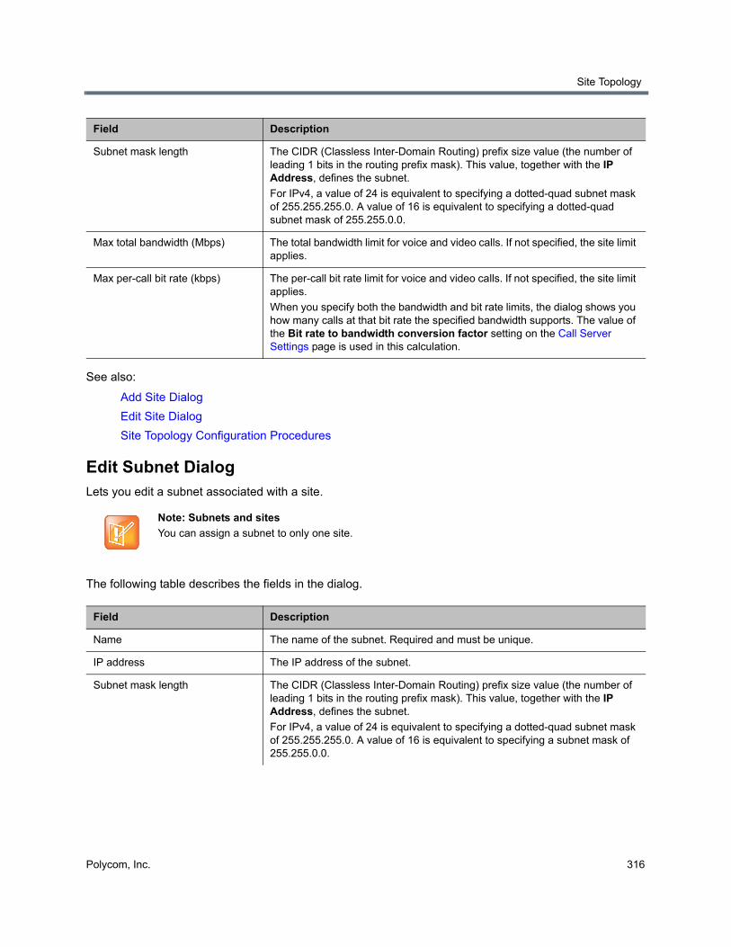
Site Topology
Polycom, Inc. 316
See also:
Add Site Dialog
Edit Site Dialog
Site Topology Configuration Procedures
Edit Subnet DialogLets you edit a subnet associated with a site.
The following table describes the fields in the dialog.
Subnet mask length The CIDR (Classless Inter-Domain Routing) prefix size value (the number of leading 1 bits in the routing prefix mask). This value, together with the IP Address, defines the subnet.
For IPv4, a value of 24 is equivalent to specifying a dotted-quad subnet mask of 255.255.255.0. A value of 16 is equivalent to specifying a dotted-quad subnet mask of 255.255.0.0.
Max total bandwidth (Mbps) The total bandwidth limit for voice and video calls. If not specified, the site limit applies.
Max per-call bit rate (kbps) The per-call bit rate limit for voice and video calls. If not specified, the site limit applies.
When you specify both the bandwidth and bit rate limits, the dialog shows you how many calls at that bit rate the specified bandwidth supports. The value of the Bit rate to bandwidth conversion factor setting on the Call Server Settings page is used in this calculation.
Note: Subnets and sites
You can assign a subnet to only one site.
Field Description
Name The name of the subnet. Required and must be unique.
IP address The IP address of the subnet.
Subnet mask length The CIDR (Classless Inter-Domain Routing) prefix size value (the number of leading 1 bits in the routing prefix mask). This value, together with the IP Address, defines the subnet.
For IPv4, a value of 24 is equivalent to specifying a dotted-quad subnet mask of 255.255.255.0. A value of 16 is equivalent to specifying a subnet mask of 255.255.0.0.
Field Description
Site Topology
Polycom, Inc. 317
See also:
Add Site Dialog
Edit Site Dialog
Site Topology Configuration Procedures
Site LinksThe Site Links page contains a list of the links defined in the site topology. A link can connect two sites, or it can connect a site to an MPLS network cloud (see Network Clouds). Links between sites must be configured in order to enable calls between sites. In order for an endpoint in site A to call an endpoint in site B, there must be a link path (either direct, via other linked sites, or via an MPLS network cloud) connecting site A and site B.
An initial site link is provided with a freshly installed system, named Default Site to Internet/VPN. It links the Default site with the Internet/VPN site to allow call routing for a newly deployed system.
If the system is integrated with a RealPresence Resource Manager system, it receives this information from that system, and this page is read-only. If not, you can enter link information.
The commands in the Actions list let you add a link and edit or delete existing links.
The next table describes the fields in the list.
Max total bandwidth (Mbps) The total bandwidth limit for voice and video calls. If not specified, the site limit applies.
Max per-call bit rate (kbps) The per-call bit rate limit for voice and video calls. If not specified, the site limit applies.
When you specify both the bandwidth and bit rate limits, the dialog shows you how many calls at that bit rate the specified bandwidth supports. The value of the Bit rate to bandwidth conversion factor setting on the Call Server Settings page is used in this calculation.
Column Description
Name Name of the link.
Description Description of the link.
From Site The originating site of the link. Can’t be changed when creating a site-to-cloud link.
To Site The destination site (or MPLS cloud) of the link. Can’t be changed when creating a site-to-cloud link.
Max Total Bandwidth (Mbps) The total bandwidth limit for voice and video calls, which you set at the gateway or router.
Max Per-Call Bit Rate (kbps) The per-call bit rate limit for voice and video calls, which you set at the gateway or router.
Field Description
Site Topology
Polycom, Inc. 318
See also:
About Site Topology
Add Site Link Dialog
Edit Site Link Dialog
Site Topology Configuration Procedures
Add Site Link DialogLets you define a new site link in the Polycom RealPresence DMA system’s site topology. A link can connect two sites, or it can connect a site to an MPLS network cloud (see Network Clouds).
The following table describes the fields in the dialog.
See also:
About Site Topology
Site Links
Site Topology Configuration Procedures
Edit Site Link DialogLets you edit a site link in the Polycom RealPresence DMA system’s site topology. A link can connect two sites, or it can connect a site to an MPLS network cloud (see Network Clouds).
You can’t change the sites that a site link connects. To modify how sites are linked, delete the links to be removed and add the new links.
The following table describes the fields in the dialog.
Field Description
Name A meaningful name for the link (up to 128 characters).
Description A brief description of the link (up to 200 characters).
From site The originating site of the link.
To site The destination site of the link.
Max total bandwidth (Mbps) The total bandwidth limit for voice and video calls, which you set at the gateway or router.
Max per-call bit rate (kbps) The per-call bit rate limit for voice and video calls, which you set at the gateway or router.
When you specify both the bandwidth and bit rate limits, the dialog shows you how many calls at that bit rate the specified bandwidth supports. The value of the Bit rate to bandwidth conversion factor setting on the Call Server Settings page is used in this calculation.
Site Topology
Polycom, Inc. 319
See also:
About Site Topology
Site Links
Site Topology Configuration Procedures
Site-to-Site ExclusionsThe Site-to-Site Exclusions page contains a list of the site-to-site connections that the site topology doesn’t permit a call or session to use.
If the system is integrated with a RealPresence Resource Manager system, it receives this information from that system, and this page is read-only. If not, you can define exclusions.
The commands in the Actions list let you add a site-to-site exclusion and delete existing exclusions.
The following table describes the fields in the list.
See also:
About Site Topology
Add Site-to-Site Exclusion Wizard
Site Topology Configuration Procedures
Add Site-to-Site Exclusion WizardLets you define a new site-to-site exclusion in the Polycom RealPresence DMA system’s site topology.
Field Description
Name A meaningful name for the link (up to 128 characters).
Description A brief description of the link (up to 200 characters).
From site The originating site of the link (view only).
To site The destination site of the link (view only).
Max total bandwidth (Mbps) The total bandwidth limit for voice and video calls, which you set at the gateway or router.
Max per-call bit rate (kbps) The per-call bit rate limit for voice and video calls, which you set at the gateway or router.
When you specify both the bandwidth and bit rate limits, the dialog shows you how many calls at that bit rate the specified bandwidth supports. The value of the Bit rate to bandwidth conversion factor setting on the Call Server Settings page is used in this calculation.
Column Description
From Site Name of one of the two sites connected by the excluded link.
To Site Name of the other site.
Site Topology
Polycom, Inc. 320
To add a site-to-site exclusion
1 Go to Network > Site Topology > Site-to-Site Exclusions.
2 In the Actions list, click Add.
3 In Step 1 of the wizard, select the first site for the exclusion. Click Next.
If the site you want isn’t displayed in the list, you can search by site name or territory.
4 In Step 2 of the wizard, select the second site for the exclusion. Click Next.
5 In Step 3 of the wizard, review the exclusion and click Done if it’s correct.
See also:
Site-to-Site Exclusions
Site Topology Configuration Procedures
TerritoriesThe Territories page lists the territories defined in the site topology. On the right, it displays information about the selected territory.
A territory contains one or more sites for which a Polycom RealPresence DMA cluster is responsible. By default, there is one territory named Default DMA Territory.
In a superclustered RealPresence DMA system deployment, additional territories allow you to assign different territories to different RealPresence DMA clusters and to specify a backup cluster for each territory to increase fault tolerance. If a territory’s primary cluster becomes unavailable for any reason, the backup cluster takes over the responsibilities for the territory.
Territories serve the following purposes:
● Sites are associated with territories, thus specifying which RealPresence DMA cluster is responsible for serving as the H.323 gatekeeper, SIP registrar, and SIP proxy for each site.
● Microsoft Active Directory integration is associated with a territory, thus specifying which RealPresence DMA cluster is responsible for connecting to the directory server, retrieving user and group data, and updating the shared supercluster data.
● Microsoft Exchange server integration (for calendaring service) is associated with a territory, thus specifying which RealPresence DMA cluster is responsible for integrating with the Exchange server and monitoring the Polycom Conferencing infrastructure mailbox.
● The RealPresence DMA system’s Conference Manager functionality is associated with territories, thus specifying which Polycom RealPresence DMA clusters are responsible for hosting conference rooms (VMRs). Up to three territories (and thus clusters) may have this responsibility.
If the system is integrated with a RealPresence Resource Manager system, it receives territory information from that system, and the Territories page is view-only. If not, you can modify the territory information.
The commands in the Actions list let you add a territory and edit or delete territories, or if the system is integrated with a RealPresence Resource Manager system, view details for a territory.
The following table describes the fields in the list and the sections on the right.
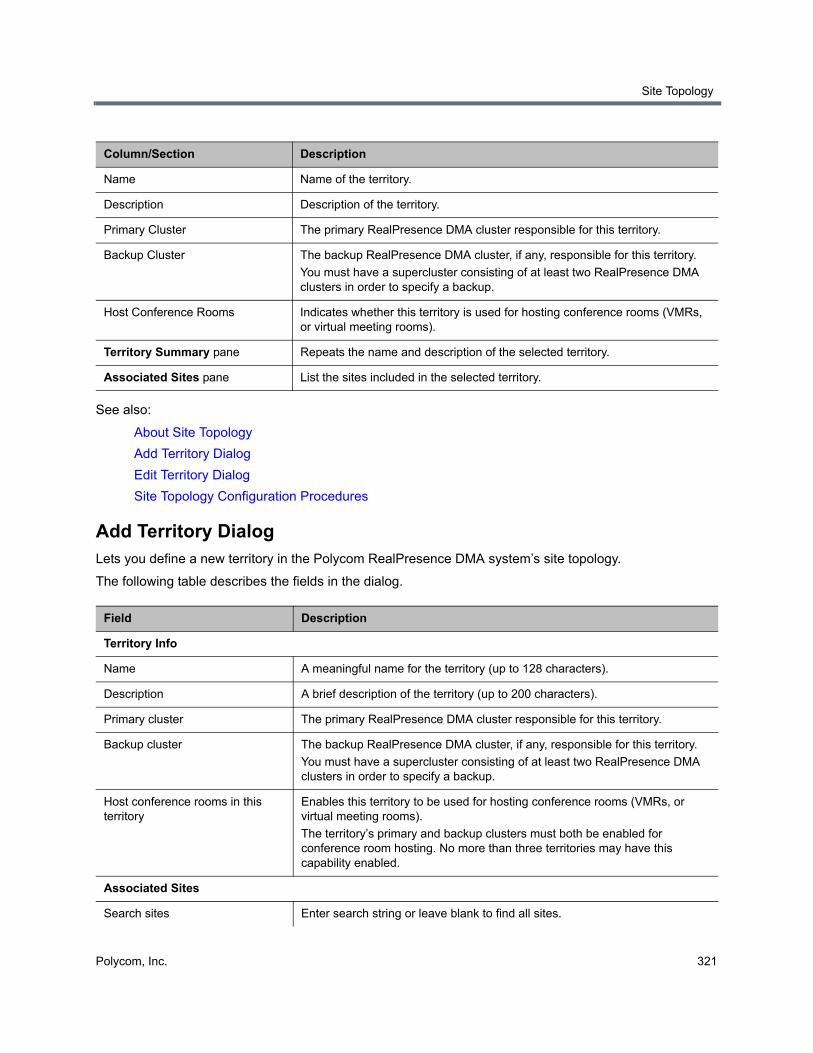
Site Topology
Polycom, Inc. 321
See also:
About Site Topology
Add Territory Dialog
Edit Territory Dialog
Site Topology Configuration Procedures
Add Territory DialogLets you define a new territory in the Polycom RealPresence DMA system’s site topology.
The following table describes the fields in the dialog.
Column/Section Description
Name Name of the territory.
Description Description of the territory.
Primary Cluster The primary RealPresence DMA cluster responsible for this territory.
Backup Cluster The backup RealPresence DMA cluster, if any, responsible for this territory.
You must have a supercluster consisting of at least two RealPresence DMA clusters in order to specify a backup.
Host Conference Rooms Indicates whether this territory is used for hosting conference rooms (VMRs, or virtual meeting rooms).
Territory Summary pane Repeats the name and description of the selected territory.
Associated Sites pane List the sites included in the selected territory.
Field Description
Territory Info
Name A meaningful name for the territory (up to 128 characters).
Description A brief description of the territory (up to 200 characters).
Primary cluster The primary RealPresence DMA cluster responsible for this territory.
Backup cluster The backup RealPresence DMA cluster, if any, responsible for this territory.
You must have a supercluster consisting of at least two RealPresence DMA clusters in order to specify a backup.
Host conference rooms in this territory
Enables this territory to be used for hosting conference rooms (VMRs, or virtual meeting rooms).
The territory’s primary and backup clusters must both be enabled for conference room hosting. No more than three territories may have this capability enabled.
Associated Sites
Search sites Enter search string or leave blank to find all sites.
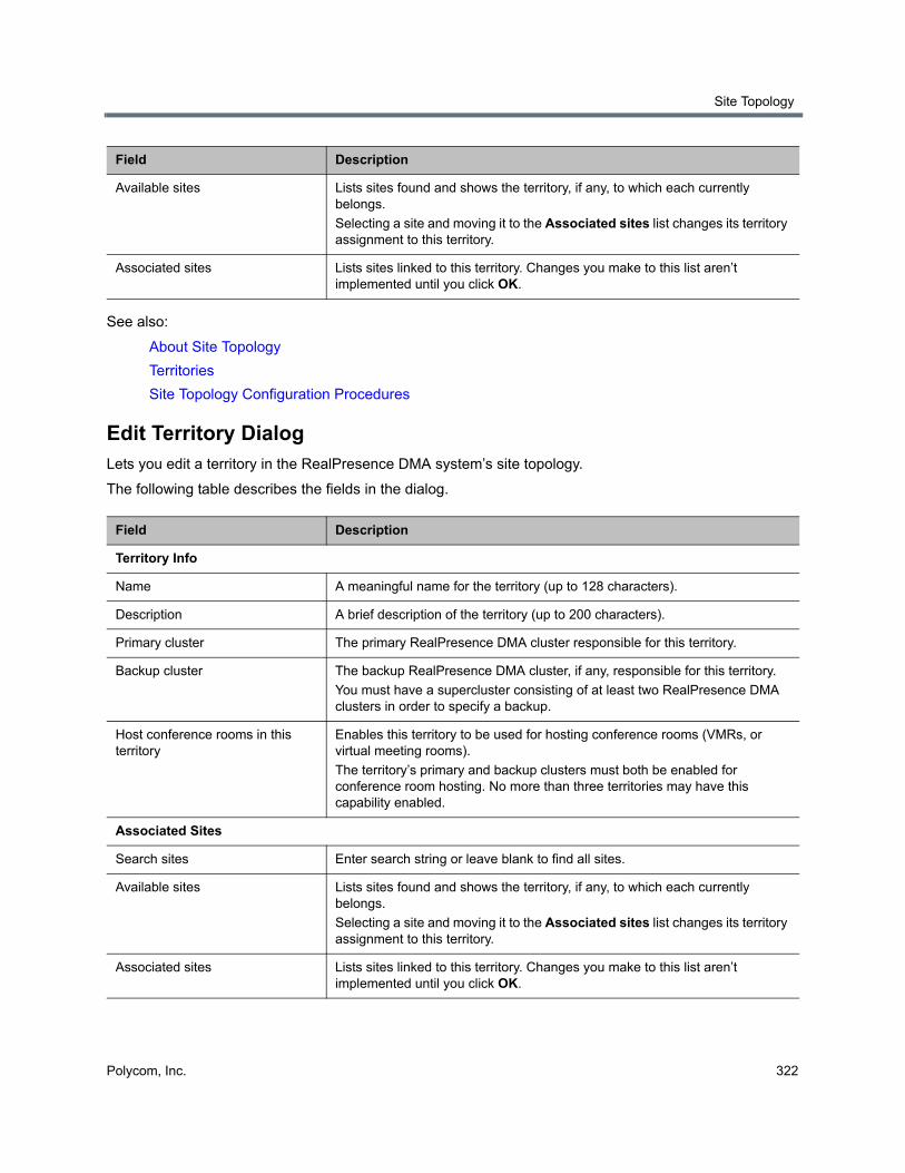
Site Topology
Polycom, Inc. 322
See also:
About Site Topology
Territories
Site Topology Configuration Procedures
Edit Territory DialogLets you edit a territory in the RealPresence DMA system’s site topology.
The following table describes the fields in the dialog.
Available sites Lists sites found and shows the territory, if any, to which each currently belongs.
Selecting a site and moving it to the Associated sites list changes its territory assignment to this territory.
Associated sites Lists sites linked to this territory. Changes you make to this list aren’t implemented until you click OK.
Field Description
Territory Info
Name A meaningful name for the territory (up to 128 characters).
Description A brief description of the territory (up to 200 characters).
Primary cluster The primary RealPresence DMA cluster responsible for this territory.
Backup cluster The backup RealPresence DMA cluster, if any, responsible for this territory.
You must have a supercluster consisting of at least two RealPresence DMA clusters in order to specify a backup.
Host conference rooms in this territory
Enables this territory to be used for hosting conference rooms (VMRs, or virtual meeting rooms).
The territory’s primary and backup clusters must both be enabled for conference room hosting. No more than three territories may have this capability enabled.
Associated Sites
Search sites Enter search string or leave blank to find all sites.
Available sites Lists sites found and shows the territory, if any, to which each currently belongs.
Selecting a site and moving it to the Associated sites list changes its territory assignment to this territory.
Associated sites Lists sites linked to this territory. Changes you make to this list aren’t implemented until you click OK.
Field Description
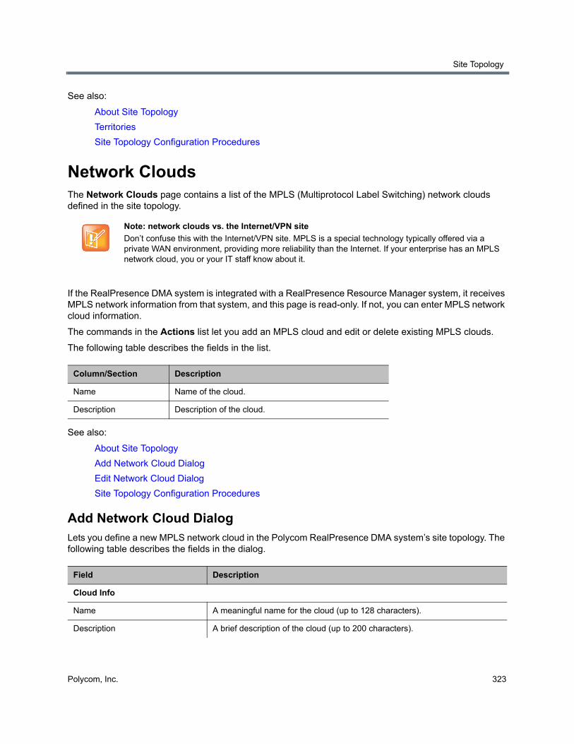
Site Topology
Polycom, Inc. 323
See also:
About Site Topology
Territories
Site Topology Configuration Procedures
Network CloudsThe Network Clouds page contains a list of the MPLS (Multiprotocol Label Switching) network clouds defined in the site topology.
If the RealPresence DMA system is integrated with a RealPresence Resource Manager system, it receives MPLS network information from that system, and this page is read-only. If not, you can enter MPLS network cloud information.
The commands in the Actions list let you add an MPLS cloud and edit or delete existing MPLS clouds.
The following table describes the fields in the list.
See also:
About Site Topology
Add Network Cloud Dialog
Edit Network Cloud Dialog
Site Topology Configuration Procedures
Add Network Cloud DialogLets you define a new MPLS network cloud in the Polycom RealPresence DMA system’s site topology. The following table describes the fields in the dialog.
Note: network clouds vs. the Internet/VPN site
Don’t confuse this with the Internet/VPN site. MPLS is a special technology typically offered via a private WAN environment, providing more reliability than the Internet. If your enterprise has an MPLS network cloud, you or your IT staff know about it.
Column/Section Description
Name Name of the cloud.
Description Description of the cloud.
Field Description
Cloud Info
Name A meaningful name for the cloud (up to 128 characters).
Description A brief description of the cloud (up to 200 characters).
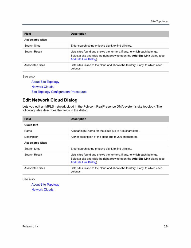
Site Topology
Polycom, Inc. 324
See also:
About Site Topology
Network Clouds
Site Topology Configuration Procedures
Edit Network Cloud DialogLets you edit an MPLS network cloud in the Polycom RealPresence DMA system’s site topology. The following table describes the fields in the dialog.
See also:
About Site Topology
Network Clouds
Associated Sites
Search Sites Enter search string or leave blank to find all sites.
Search Result Lists sites found and shows the territory, if any, to which each belongs.
Select a site and click the right arrow to open the Add Site Link dialog (see Add Site Link Dialog).
Associated Sites Lists sites linked to the cloud and shows the territory, if any, to which each belongs.
Field Description
Cloud Info
Name A meaningful name for the cloud (up to 128 characters).
Description A brief description of the cloud (up to 200 characters).
Associated Sites
Search Sites Enter search string or leave blank to find all sites.
Search Result Lists sites found and shows the territory, if any, to which each belongs.
Select a site and click the right arrow to open the Add Site Link dialog (see Add Site Link Dialog).
Associated Sites Lists sites linked to the cloud and shows the territory, if any, to which each belongs.
Field Description
Site Topology
Polycom, Inc. 325
Site Topology Configuration Procedures
To configure your site topology in the RealPresence DMA system
1 Go to Network > Site Topology > Sites.
Initially, the list of sites contains only an entry named Internet/VPN, which can’t be edited.
2 For each site in your network topology, do the following:
a In the Actions list, click Add.
b In the Add Site dialog, complete the General Info section. See Add Site Dialog.
c To enable IP calls to/from the site, complete the ISDN Number Assignment, H.323 Routing and/or SIP Routing sections.
d In the Subnets section, specify the subnet or subnets that make up the site. See Add Subnet Dialog.
e Click OK.
3 Go to Network > Site Topology > Territories.
The list of territories contains an entry named Default RealPresence DMA Territory. It’s assigned to this RealPresence DMA system cluster. You can edit this entry, including changing its name and assigning sites to it.
4 Edit the Default RealPresence DMA Territory entry:
a Select the entry and, in the Actions list, click Edit.
The Edit Territory dialog appears.
b In the Territory Info section, change the name and description for this territory if desired. Assign a primary and backup cluster for the territory, and elect whether to host conference rooms in this territory (the primary and backup cluster must be licensed for this capability).
c In the Associated Sites section, add all the sites to the territory. See Edit Territory Dialog.
d Click OK.
5 Add other territories by clicking Add in the Actions list and completing the same settings in the Add Territory dialog.
6 Go to Network > Site Topology > Site Links, and for each direct link between sites, do the following:
a In the Actions list, click Add.
b In the Add Site Link dialog, define the link. See Add Site Link Dialog.
c Click OK.
7 Go to Network > Site Topology > Network Clouds, and for each MPLS network cloud in your network topology, do the following:
a In the Actions list, click Add.
The Add Network Cloud dialog appears.
b In the Cloud Info section, enter a name and description for the cloud.
c In the Linked Sites section, display the sites you defined. See Add Network Cloud Dialog.
d Select the first site linked to this cloud and click the arrow button to move it to the Linked Sites list.
The Add Site Link dialog appears.
Site Topology
Polycom, Inc. 326
e Define the link. See Add Site Link Dialog.
f Repeat the previous two steps for each additional site linked to this cloud.
g Click OK.
8 Go to Network > Site Topology > Site-to-Site Exclusions, and for each exclusion in your network topology, do the following:
a In the Actions list, click Add.
b Complete the Add Site-to-Site Exclusions wizard. See Add Site-to-Site Exclusion Wizard.
Your site topology information is complete. For a conference with cascading for bandwidth enabled, the RealPresence DMA system can use it to route calls to the nearest eligible MCU (based on pools and pool orders) that has available capacity and to create the cascade links between MCUs.
See also:
About Site Topology
Note: RealPresence Resource Manager integration replaces data
If in the future you integrate this system with a RealPresence Resource Manager system, the site topology information from the RealPresence Resource Manager system will replace the information you entered.
Polycom, Inc. 327
Users and Groups
This section describes the following Polycom® RealPresence® Distributed Media Application™ (DMA®) 7000 system management topics related to users and groups:
● User Roles Overview
● Adding Users Overview
● Users
● Groups
● Login Sessions
● Change Password Dialog
User Roles OverviewThe Polycom RealPresence DMA system has four user roles, or classes of users, each with its own set of permissions. Every user account has one or more user roles (but only three of the four roles must be explicitly assigned).
The following table briefly describes the user roles. See Polycom RealPresence DMA System User Roles and Their Access Privileges for detailed information on which commands are available to each user role.
Role Description
Administrator Responsible for the overall administration of the system.
Can access all the pages except those reserved for auditors (must be an enterprise user to see enterprise reports, enterprise users, and groups).
If you have a Polycom RealPresence Resource Manager system, assign this role to its login account. If API access for other clients is enabled, assign this role to the login account of any other API client that should have administrative rights and responsibilities.
This role must be explicitly assigned by an Administrator.
Auditor Responsible for configuring logging and history record retention, and for managing logs. Can access all history reports.
This role must be explicitly assigned by an Administrator.
Users and Groups
Polycom, Inc. 328
If your system is integrated with an Active Directory, all enterprise users are automatically Conferencing Users. You can use enterprise groups to manage assignment of the other user roles. See Enterprise Groups Procedures.
See also:
Users
Users Procedures
Conference Rooms Procedures
Adding Users OverviewYou can add users to the system in two ways:
● Add users manually to the Polycom RealPresence DMA system. These are known as local users. When adding users manually, you must assign them conference rooms and any specific roles they should have.
● Integrate the Polycom RealPresence DMA system with Microsoft Active Directory (requires Administrator permissions). This integration allows users with specific roles (Administrator, Auditor, or Provisioner) to log into the Polycom RealPresence DMA system with their Active Directory (AD) user names and passwords. The integration process can also automatically create conference rooms for AD users based on the AD field (such as phone number) that you specify.
When a Polycom RealPresence DMA system is integrated with an Active Directory, the Active Directory users are automatically added as Polycom RealPresence DMA system users with a Conferencing User role and displayed in the Polycom RealPresence DMA system Users list. An administrator can assign them additional roles as required.
Provisioner Responsible for the management of Conferencing User accounts.
Can create or modify only users with no role other than Conferencing User, but can view all local users. Must be an enterprise user to view all enterprise users. Can view history reports.
If you have a Polycom RealPresence Resource Manager system or any other API client, assign this role to its users who should have provisioning rights and responsibilities.
This role must be explicitly assigned by an Administrator.
Conferencing User Has been provisioned with a conference room (virtual meeting room, or VMR) or rooms and can host conferences. Cannot access the system management interface.
This role is automatically present on all user accounts. It isn’t listed under Available Roles or explicitly assigned.
For purposes of API access, the system identifies a subcategory of Conferencing User, the Conference Room Owner, who can monitor and control his or her conferences.
Note: A user account that has neither a conference room nor an explicitly assigned role serves no purpose.
Note: Enterprise vs. local users
You must be an enterprise user (with the appropriate user role assignments) to see and work with enterprise users. A local user can only see other local users, regardless of user roles.
Role Description
Users and Groups
Polycom, Inc. 329
A newly installed system has two local user accounts: admin and rppuser. The rppuser account is populated with the factory default configuration, has the same default password as admin, and is not assigned any user roles. Five VMRs are assigned to the rppuser account, all of which are configured with factory default settings. You can use these VMRs to make test calls on a newly deployed system.
The admin account is a user account with Administrator privileges. We strongly recommend that, as part of initial system setup, you create a local user account for yourself with the Administrator role, log in using that account, and delete the admin user account. See the caution and first procedure in Users Procedures.
You can then create other local user accounts or integrate with an Active Directory and assign additional roles to the appropriate enterprise users.
Integration with an Active Directory is described in Microsoft Active Directory® Integration.
If you have a Polycom RealPresence Resource Manager that you want to integrate with the Polycom RealPresence DMA system, you must create a local user account for the RealPresence Resource Manager system, which enables it to log into the RealPresence DMA system’s RealPresence Platform API. This account should have administrator and provisioner roles.
The RealPresence Resource Manager user owns the conference rooms (VMRs) it creates for preset dial-out conferences (called Anytime conferences in the RealPresence Resource Manager system).
See also:
Polycom RealPresence DMA System Initial Configuration Summary
User Roles Overview
Users Procedures
Conference Rooms Procedures
UsersThe Users page provides access to information about both local and enterprise users. From it, you can:
● Add local users.
● Edit both local and enterprise users (for the latter, only roles and conference passcodes can be modified).
● Manage conference rooms (virtual meeting rooms, or VMRs) for both local and enterprise users.
Note: Enterprise vs. local users
You must be an enterprise user (with the appropriate user role assignments) to see and work with enterprise users. A local user can only see other local users, regardless of user roles.
Caution: API client connections
If you have a Polycom RealPresence Resource Manager system (or another API client) that connects to the RealPresence DMA system’s RealPresence Platform API, be aware that authorized users of that system (or other API client) can add local users, edit passcodes, add and edit conference rooms (VMRs), and view information about users and conference rooms. (Ordinary Conferencing Users can only access their own user information and the conference rooms they own.)
In particular, the RealPresence Resource Manager system itself has a user login (see Adding Users Overview), and it owns the conference rooms created in its scheduling interface for preset dial-out conferences (referred to as Anytime conferences in the RealPresence Resource Manager system).
Users and Groups
Polycom, Inc. 330
The search pane above the list lets you find users matching the criteria you specify. Click the down arrow on the right to expand the search pane, providing access to more search fields and filters.
The system matches any string you enter against the beginning of the value for which you’re searching. For the Search users field at the top, it matches against user ID, first name, and last name. For instance, if you enter “sa” in the Search users field, it displays the users whose user ID, first name, or last name begins with “sa.”
To search for a string not at the beginning of the field, you can use an asterisk (*) as a wildcard. You can restrict the search to local users by selecting the check box.
The users that match your search criteria (up to 500) are listed below. If there are more than 500 results, you can scroll between groups of results using the pagination buttons, found below the list of results at the lower left of the window.
The following table describes the parts of the Users list.
Column Description
User ID The user’s login name. The icon to the left indicates whether the user’s account is enabled or disabled. Hover over it to see the associated message.
First Name The user’s first name.
Last Name The user’s last name.
Domain The domain associated with the user. All users added manually to the system are in the LOCAL domain.
Class of Service The class of service assigned to the user, which determines the priority of the user’s calls.
Note: The class of service of the device applies to point to point calls. VMR calls use the class of service of the conference room.
Conference Rooms The user’s conference room or rooms (virtual meeting rooms, or VMRs).
If the system is integrated with an Active Directory, and you specified criteria for conference room ID generation, the enterprise users have a default conference room assigned to them automatically.
Alternatively or in addition, enterprise users may have custom conference rooms manually assigned to them. Local users must be manually assigned a conference room or rooms.
Note: A user account that has neither a conference room nor an explicitly assigned role serves no purpose.
Roles The user’s explicitly assigned user roles. All users automatically have the Conferencing User role; it’s not listed or explicitly assigned (but a conference room ID is required). See User Roles Overview.
Users and Groups
Polycom, Inc. 331
See also:
User Roles Overview
Adding Users Overview
Add User Dialog
Edit User Dialog
Conference Rooms Dialog
Users Procedures
Conference Rooms Procedures
Add User DialogThe following table describes the parts of the Add User dialog, which lets you add local users to the system.
Associated Endpoints The endpoints associated with the user, if any.
Passcodes The numeric passcodes specified for this user, if any:
• Chairperson passcode — Passcode that identifies chairpersons in the user’s conferences.
• Conference passcode — Passcode that callers must enter to join the user’s conferences.
For enterprise users, passcodes (both kinds) generally come from the Active Directory. See Add Passcodes for Enterprise Users. But you can specify an enterprise user’s passcodes locally. See Edit User Dialog.
For local users, you can add passcodes when you create or edit the users. See Add User Dialog.
Whether passcodes are specified for the user or not, you can add or change them for a specific conference room of the user’s. See Edit Conference Room Dialog.
Field Description
General Info
First name The local user’s first name.
Last name The local user’s last name.
User ID The local user’s login name.
Password
Confirm password
The local user’s system login password (not conference or chairperson passcode). This is the password that enables users with explicitly assigned roles to log into the system management interface (see User Roles Overview).
The password must satisfy the local password rules specified for the system (see Local Password).
Column Description
Users and Groups
Polycom, Inc. 332
User pass-through to CDR Optional value to put in the userDataA field of call CDRs associated with this user.
For instance, this might be a user ID from some external system or database.
Account disabled If checked, the user can’t host conferences (the user’s conference room or rooms are not available) and can’t access the system management interface.
Conference room territory The territory to which the user’s conference rooms (virtual meeting rooms, or VMRs) are assigned.
A conference room’s territory assignment determines which RealPresence DMA cluster hosts its conferences (the primary cluster for the territory, or its backup cluster if necessary).
If not selected, the user’s conference rooms are assigned as follows (in priority order listed):
• To the territory associated with the room specifically (see Conference Rooms Dialog).
• Otherwise, to the territory associated with the AD group the user belongs to (if more than one, the lexically first group) (see Edit Group Dialog).
• Otherwise, the system’s default territory (see Conference Settings).
Class of service Select to assign the user a class of service, which determines the priority of the user’s calls.
If not selected, the user receives the highest class of service associated with any group to which the user belongs, or if none, the system’s default class of service. See Conference Settings.
Note: A class of service may also be assigned to an endpoint. See Endpoints.
Note: The class of service of the device applies to point to point calls. VMR calls use the class of service of the conference room.
Maximum bit rate (kbps) If Class of service is selected, lets you specify the maximum bit rate for the user.
Minimum downspeed rate (kbps) If Class of service is selected, lets you specify the minimum bit rate to which the user’s calls can be reduced (downspeeded).
Associated Endpoints
Associated endpoints Lists the endpoints associated with the user. Click Select to open the Select Associated Endpoints dialog and associate an endpoint with the user (see Select Associated Endpoints Dialog).
Click Delete to delete an associated endpoint. A dialog prompts you to confirm.
Note: You can also manage endpoint associations on the Endpoints page (see Associate User Dialog). But if the Polycom RealPresence DMA system is integrated with a Polycom RealPresence Resource Manager system, it receives user-to-device association information from that system, and you can only associate users with devices on the Polycom RealPresence Resource Manager system.
Field Description
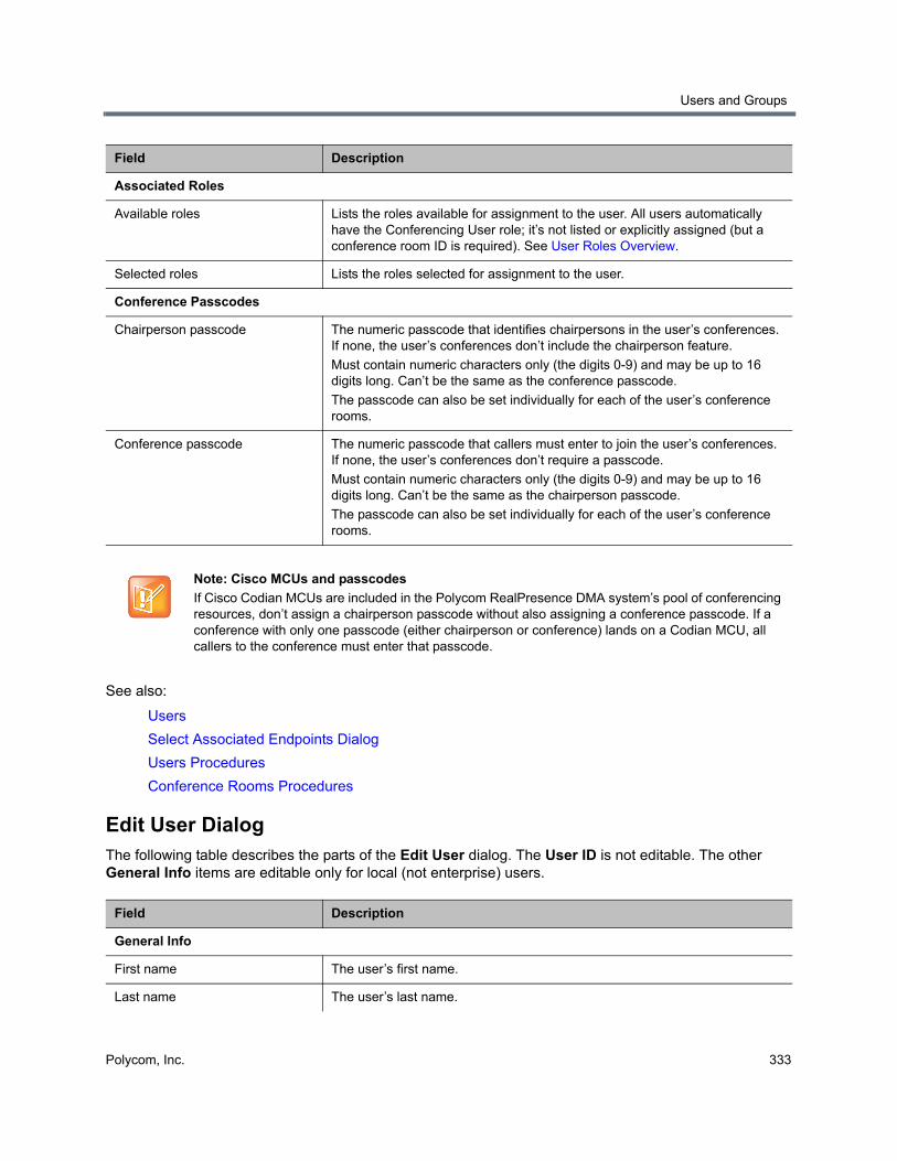
Users and Groups
Polycom, Inc. 333
See also:
Users
Select Associated Endpoints Dialog
Users Procedures
Conference Rooms Procedures
Edit User DialogThe following table describes the parts of the Edit User dialog. The User ID is not editable. The other General Info items are editable only for local (not enterprise) users.
Associated Roles
Available roles Lists the roles available for assignment to the user. All users automatically have the Conferencing User role; it’s not listed or explicitly assigned (but a conference room ID is required). See User Roles Overview.
Selected roles Lists the roles selected for assignment to the user.
Conference Passcodes
Chairperson passcode The numeric passcode that identifies chairpersons in the user’s conferences. If none, the user’s conferences don’t include the chairperson feature.
Must contain numeric characters only (the digits 0-9) and may be up to 16 digits long. Can’t be the same as the conference passcode.
The passcode can also be set individually for each of the user’s conference rooms.
Conference passcode The numeric passcode that callers must enter to join the user’s conferences. If none, the user’s conferences don’t require a passcode.
Must contain numeric characters only (the digits 0-9) and may be up to 16 digits long. Can’t be the same as the chairperson passcode.
The passcode can also be set individually for each of the user’s conference rooms.
Note: Cisco MCUs and passcodes
If Cisco Codian MCUs are included in the Polycom RealPresence DMA system’s pool of conferencing resources, don’t assign a chairperson passcode without also assigning a conference passcode. If a conference with only one passcode (either chairperson or conference) lands on a Codian MCU, all callers to the conference must enter that passcode.
Field Description
General Info
First name The user’s first name.
Last name The user’s last name.
Field Description
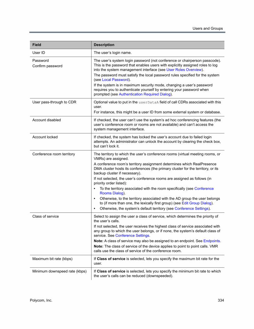
Users and Groups
Polycom, Inc. 334
User ID The user’s login name.
Password
Confirm password
The user’s system login password (not conference or chairperson passcode). This is the password that enables users with explicitly assigned roles to log into the system management interface (see User Roles Overview).
The password must satisfy the local password rules specified for the system (see Local Password).
If the system is in maximum security mode, changing a user’s password requires you to authenticate yourself by entering your password when prompted (see Authentication Required Dialog).
User pass-through to CDR Optional value to put in the userDataA field of call CDRs associated with this user.
For instance, this might be a user ID from some external system or database.
Account disabled If checked, the user can’t use the system’s ad hoc conferencing features (the user’s conference room or rooms are not available) and can’t access the system management interface.
Account locked If checked, the system has locked the user’s account due to failed login attempts. An administrator can unlock the account by clearing the check box, but can’t lock it.
Conference room territory The territory to which the user’s conference rooms (virtual meeting rooms, or VMRs) are assigned.
A conference room’s territory assignment determines which RealPresence DMA cluster hosts its conferences (the primary cluster for the territory, or its backup cluster if necessary).
If not selected, the user’s conference rooms are assigned as follows (in priority order listed):
• To the territory associated with the room specifically (see Conference Rooms Dialog).
• Otherwise, to the territory associated with the AD group the user belongs to (if more than one, the lexically first group) (see Edit Group Dialog).
• Otherwise, the system’s default territory (see Conference Settings).
Class of service Select to assign the user a class of service, which determines the priority of the user’s calls.
If not selected, the user receives the highest class of service associated with any group to which the user belongs, or if none, the system’s default class of service. See Conference Settings.
Note: A class of service may also be assigned to an endpoint. See Endpoints.
Note: The class of service of the device applies to point to point calls. VMR calls use the class of service of the conference room.
Maximum bit rate (kbps) If Class of service is selected, lets you specify the maximum bit rate for the user.
Minimum downspeed rate (kbps) If Class of service is selected, lets you specify the minimum bit rate to which the user’s calls can be reduced (downspeeded).
Field Description
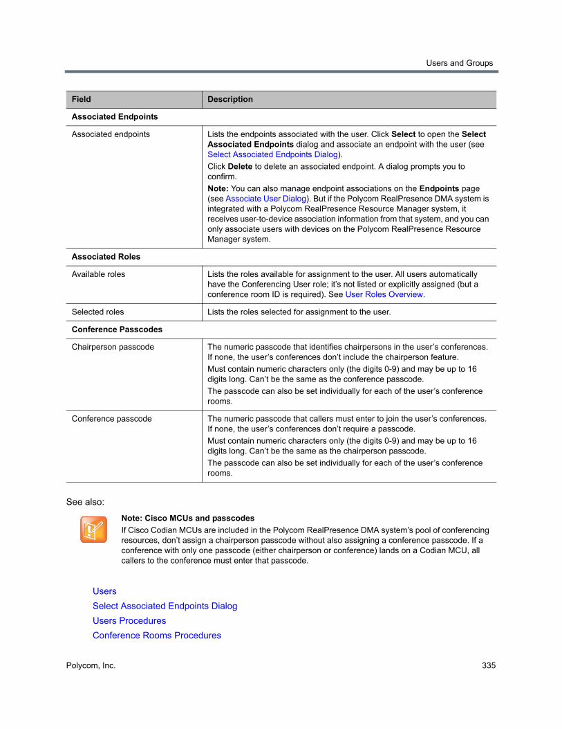
Users and Groups
Polycom, Inc. 335
See also:
Users
Select Associated Endpoints Dialog
Users Procedures
Conference Rooms Procedures
Associated Endpoints
Associated endpoints Lists the endpoints associated with the user. Click Select to open the Select Associated Endpoints dialog and associate an endpoint with the user (see Select Associated Endpoints Dialog).
Click Delete to delete an associated endpoint. A dialog prompts you to confirm.
Note: You can also manage endpoint associations on the Endpoints page (see Associate User Dialog). But if the Polycom RealPresence DMA system is integrated with a Polycom RealPresence Resource Manager system, it receives user-to-device association information from that system, and you can only associate users with devices on the Polycom RealPresence Resource Manager system.
Associated Roles
Available roles Lists the roles available for assignment to the user. All users automatically have the Conferencing User role; it’s not listed or explicitly assigned (but a conference room ID is required). See User Roles Overview.
Selected roles Lists the roles selected for assignment to the user.
Conference Passcodes
Chairperson passcode The numeric passcode that identifies chairpersons in the user’s conferences. If none, the user’s conferences don’t include the chairperson feature.
Must contain numeric characters only (the digits 0-9) and may be up to 16 digits long. Can’t be the same as the conference passcode.
The passcode can also be set individually for each of the user’s conference rooms.
Conference passcode The numeric passcode that callers must enter to join the user’s conferences. If none, the user’s conferences don’t require a passcode.
Must contain numeric characters only (the digits 0-9) and may be up to 16 digits long. Can’t be the same as the chairperson passcode.
The passcode can also be set individually for each of the user’s conference rooms.
Note: Cisco MCUs and passcodes
If Cisco Codian MCUs are included in the Polycom RealPresence DMA system’s pool of conferencing resources, don’t assign a chairperson passcode without also assigning a conference passcode. If a conference with only one passcode (either chairperson or conference) lands on a Codian MCU, all callers to the conference must enter that passcode.
Field Description

Users and Groups
Polycom, Inc. 336
Authentication Required DialogIn maximum security mode, changing a user’s password requires you to authenticate yourself. Enter your password and click OK.
See also:
Edit User Dialog
Select Associated Endpoints Dialog
Lets you associate an endpoint with the selected user.
Use the search fields at the top of the dialog to find the endpoint you want to associate with this user. Select it in the table below and click OK. The dialog closes and the endpoint is added to the user’s Associated endpoints list.
See also:
Add User Dialog
Edit User Dialog
Conference Rooms DialogLets you view, add, edit, and delete the selected user’s conference rooms (virtual meeting rooms, or VMRs). A user may have three kinds of conference rooms:
● One enterprise conference room (if this is an enterprise user) automatically assigned to the user as part of the Active Directory integration process. You can’t delete this conference room, but you can modify it.
● Custom conference rooms manually added using the Add command in this dialog.
● Calendared conference rooms created automatically when the user uses the Polycom Conferencing Add-in for Microsoft Outlook to set up Polycom Conference meetings in Outlook. You can modify some of the settings for these conference rooms, but not the ones set in the meeting invitation.
In addition, if you have a Polycom RealPresence Resource Manager system connected to the RealPresence DMA system’s RealPresence Platform API, the RealPresence Resource Manager system can create conference rooms (VMRs) in the RealPresence DMA system. There are two kinds:
Note: RealPresence Resource Manager integration and user-to-device association
If the Polycom RealPresence DMA system is integrated with a Polycom RealPresence Resource Manager system, it receives user-to-device association information from that system, and you can only associate users with devices on the Polycom RealPresence Resource Manager system.
Note: Managing endpoint associations
You can also manage endpoint associations on the Endpoints page (see Associate User Dialog).
Note: User accounts need assigned rooms or roles
A user account that has neither a conference room nor an explicitly assigned role serves no purpose.
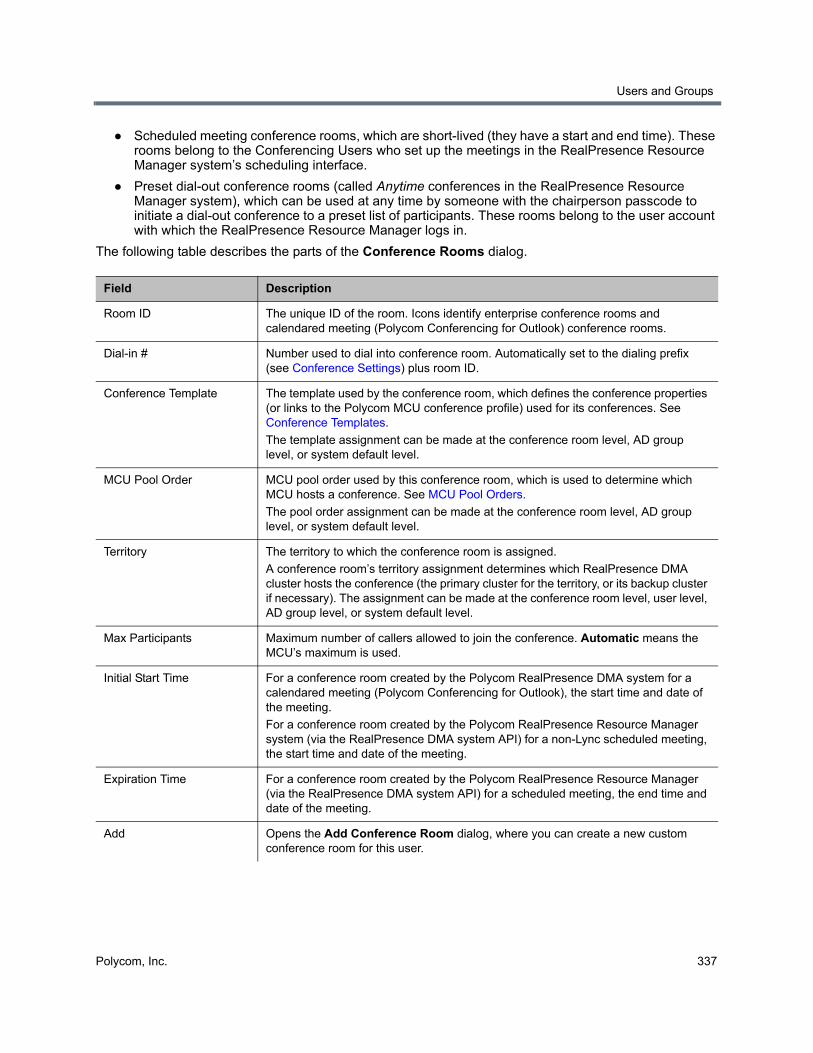
Users and Groups
Polycom, Inc. 337
● Scheduled meeting conference rooms, which are short-lived (they have a start and end time). These rooms belong to the Conferencing Users who set up the meetings in the RealPresence Resource Manager system’s scheduling interface.
● Preset dial-out conference rooms (called Anytime conferences in the RealPresence Resource Manager system), which can be used at any time by someone with the chairperson passcode to initiate a dial-out conference to a preset list of participants. These rooms belong to the user account with which the RealPresence Resource Manager logs in.
The following table describes the parts of the Conference Rooms dialog.
Field Description
Room ID The unique ID of the room. Icons identify enterprise conference rooms and calendared meeting (Polycom Conferencing for Outlook) conference rooms.
Dial-in # Number used to dial into conference room. Automatically set to the dialing prefix (see Conference Settings) plus room ID.
Conference Template The template used by the conference room, which defines the conference properties (or links to the Polycom MCU conference profile) used for its conferences. See Conference Templates.
The template assignment can be made at the conference room level, AD group level, or system default level.
MCU Pool Order MCU pool order used by this conference room, which is used to determine which MCU hosts a conference. See MCU Pool Orders.
The pool order assignment can be made at the conference room level, AD group level, or system default level.
Territory The territory to which the conference room is assigned.
A conference room’s territory assignment determines which RealPresence DMA cluster hosts the conference (the primary cluster for the territory, or its backup cluster if necessary). The assignment can be made at the conference room level, user level, AD group level, or system default level.
Max Participants Maximum number of callers allowed to join the conference. Automatic means the MCU’s maximum is used.
Initial Start Time For a conference room created by the Polycom RealPresence DMA system for a calendared meeting (Polycom Conferencing for Outlook), the start time and date of the meeting.
For a conference room created by the Polycom RealPresence Resource Manager system (via the RealPresence DMA system API) for a non-Lync scheduled meeting, the start time and date of the meeting.
Expiration Time For a conference room created by the Polycom RealPresence Resource Manager (via the RealPresence DMA system API) for a scheduled meeting, the end time and date of the meeting.
Add Opens the Add Conference Room dialog, where you can create a new custom conference room for this user.
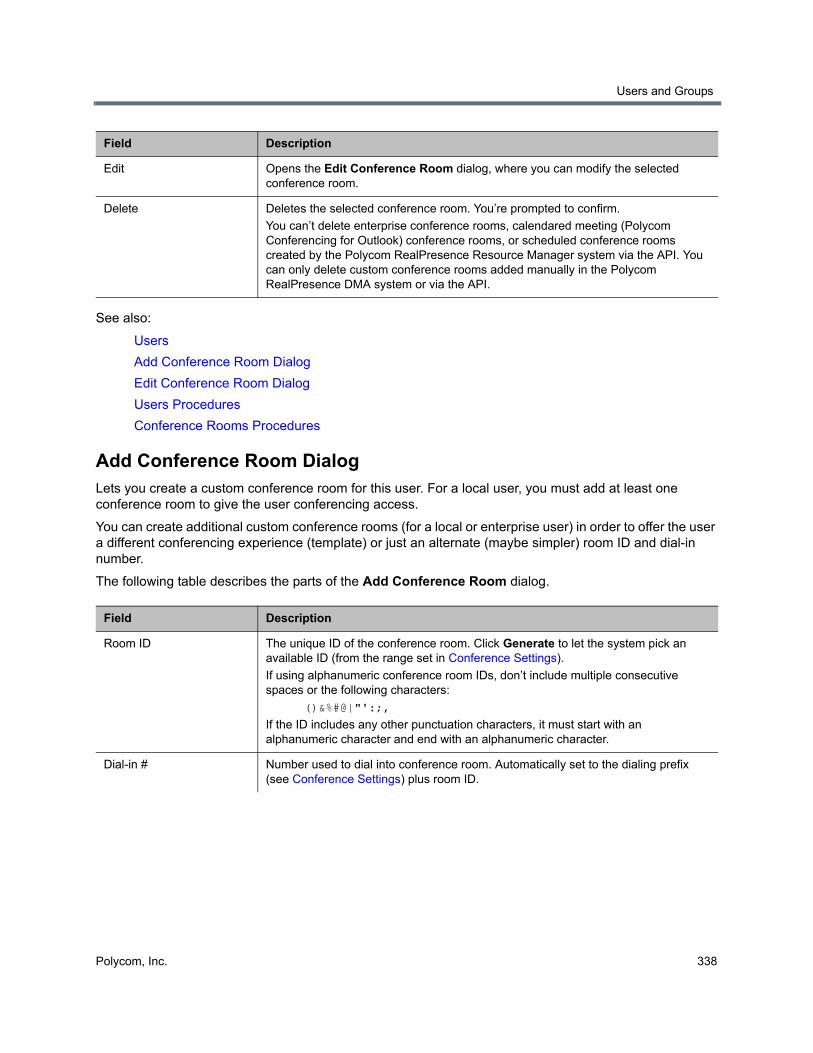
Users and Groups
Polycom, Inc. 338
See also:
Users
Add Conference Room Dialog
Edit Conference Room Dialog
Users Procedures
Conference Rooms Procedures
Add Conference Room DialogLets you create a custom conference room for this user. For a local user, you must add at least one conference room to give the user conferencing access.
You can create additional custom conference rooms (for a local or enterprise user) in order to offer the user a different conferencing experience (template) or just an alternate (maybe simpler) room ID and dial-in number.
The following table describes the parts of the Add Conference Room dialog.
Edit Opens the Edit Conference Room dialog, where you can modify the selected conference room.
Delete Deletes the selected conference room. You’re prompted to confirm.
You can’t delete enterprise conference rooms, calendared meeting (Polycom Conferencing for Outlook) conference rooms, or scheduled conference rooms created by the Polycom RealPresence Resource Manager system via the API. You can only delete custom conference rooms added manually in the Polycom RealPresence DMA system or via the API.
Field Description
Room ID The unique ID of the conference room. Click Generate to let the system pick an available ID (from the range set in Conference Settings).
If using alphanumeric conference room IDs, don’t include multiple consecutive spaces or the following characters:
()&%#@|"':;,
If the ID includes any other punctuation characters, it must start with an alphanumeric character and end with an alphanumeric character.
Dial-in # Number used to dial into conference room. Automatically set to the dialing prefix (see Conference Settings) plus room ID.
Field Description

Users and Groups
Polycom, Inc. 339
Territory The territory to which the conference room is assigned.
A conference room’s territory assignment determines which RealPresence DMA cluster hosts its conferences (the primary cluster for the territory, or its backup cluster if necessary).
If not selected, the conference room is assigned as follows (in priority order listed):
• To the territory associated with the user (see Edit User Dialog).
• Otherwise, to the territory associated with the AD group the user belongs to (if more than one, the lexically first group) (see Edit Group Dialog).
• Otherwise, the system’s default territory (see Conference Settings).
Conference template The template used by the conference room, which defines the conference properties (or links to the Polycom MCU conference profile) used for its conferences (see Conference Templates).
If not selected, the room uses the highest-priority template associated with any group to which the user belongs, or if none, the system’s default template (see Conference Settings).
Caution: If this template is linked to a RealPresence Collaboration Server or RMX profile, the profile’s IVR service determines whether callers are prompted for passcodes:
• If the profile’s IVR service prompts for passcodes, callers are prompted even if the conference doesn’t have a passcode.
• If the profile’s IVR service doesn’t prompt for passcodes, callers aren’t prompted even if the conference has a conference or chairperson passcode.
MCU pool order MCU pool order used by this conference room, which is used to determine which MCU hosts a conference. See MCU Pool Orders.
If not selected, the room uses the highest-priority pool order associated with any group to which the user belongs, or if none, the system’s default pool order (see Conference Settings).
MCU Selection The method for the RealPresence DMA system to use when it selects MCUs from MCU pool orders:
Prefer MCU in first MCU pool ensures that the DMA system always routes the call to the first available MCU in the first MCU pool. If no MCU is available, the system searches the second MCU pool for an available MCU, and so on.
Prefer MCU in first caller’s site matches the MCU chosen for the call with the site that the first caller’s endpoint belongs to.
Max participants Maximum number of callers allowed to join the conference. Automatic means the MCU’s maximum is used.
If not selected, the room uses the system’s default maximum (see Conference Settings).
Chairperson passcode The numeric passcode that identifies chairpersons in this room’s conferences. If none, the room’s conferences don’t include the chairperson feature.
If the user has a chairperson passcode, it appears here. You can change it to a different passcode for this room only.
Must contain numeric characters only (the digits 0-9) and may be up to 16 digits long. Can’t be the same as the conference passcode.
Note: See caution for Conference template field above.
Field Description
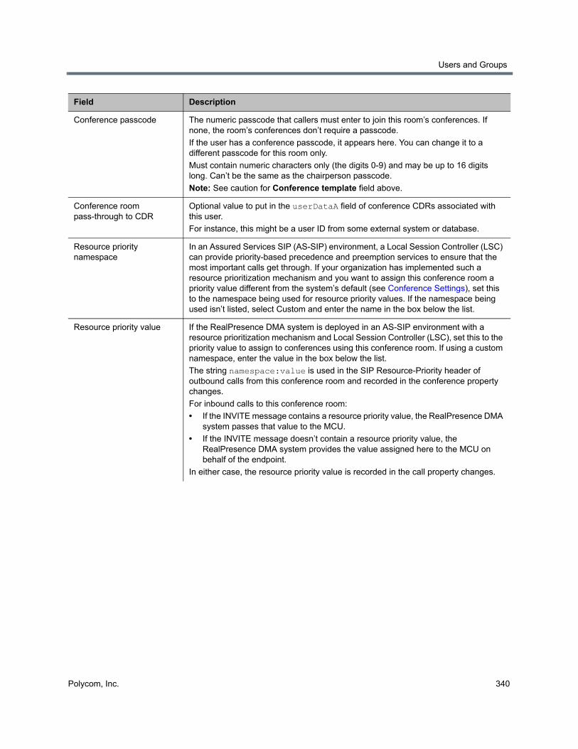
Users and Groups
Polycom, Inc. 340
Conference passcode The numeric passcode that callers must enter to join this room’s conferences. If none, the room’s conferences don’t require a passcode.
If the user has a conference passcode, it appears here. You can change it to a different passcode for this room only.
Must contain numeric characters only (the digits 0-9) and may be up to 16 digits long. Can’t be the same as the chairperson passcode.
Note: See caution for Conference template field above.
Conference room pass-through to CDR
Optional value to put in the userDataA field of conference CDRs associated with this user.
For instance, this might be a user ID from some external system or database.
Resource priority namespace
In an Assured Services SIP (AS-SIP) environment, a Local Session Controller (LSC) can provide priority-based precedence and preemption services to ensure that the most important calls get through. If your organization has implemented such a resource prioritization mechanism and you want to assign this conference room a priority value different from the system’s default (see Conference Settings), set this to the namespace being used for resource priority values. If the namespace being used isn’t listed, select Custom and enter the name in the box below the list.
Resource priority value If the RealPresence DMA system is deployed in an AS-SIP environment with a resource prioritization mechanism and Local Session Controller (LSC), set this to the priority value to assign to conferences using this conference room. If using a custom namespace, enter the value in the box below the list.
The string namespace:value is used in the SIP Resource-Priority header of outbound calls from this conference room and recorded in the conference property changes.
For inbound calls to this conference room:
• If the INVITE message contains a resource priority value, the RealPresence DMA system passes that value to the MCU.
• If the INVITE message doesn’t contain a resource priority value, the RealPresence DMA system provides the value assigned here to the MCU on behalf of the endpoint.
In either case, the resource priority value is recorded in the call property changes.
Field Description
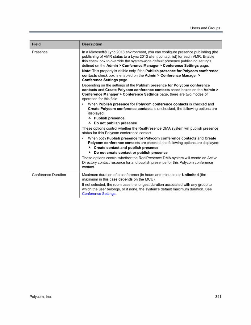
Users and Groups
Polycom, Inc. 341
Presence In a Microsoft® Lync 2013 environment, you can configure presence publishing (the publishing of VMR status to a Lync 2013 client contact list) for each VMR. Enable this check box to override the system-wide default presence publishing settings defined on the Admin > Conference Manager > Conference Settings page.
Note: This property is visible only if the Publish presence for Polycom conference contacts check box is enabled on the Admin > Conference Manager > Conference Settings page.
Depending on the settings of the Publish presence for Polycom conference contacts and Create Polycom conference contacts check boxes on the Admin > Conference Manager > Conference Settings page, there are two modes of operation for this field:
• When Publish presence for Polycom conference contacts is checked and Create Polycom conference contacts is unchecked, the following options are displayed: Publish presence Do not publish presence
These options control whether the RealPresence DMA system will publish presence status for this Polycom conference contact.
• When both Publish presence for Polycom conference contacts and Create Polycom conference contacts are checked, the following options are displayed: Create contact and publish presence Do not create contact or publish presence
These options control whether the RealPresence DMA system will create an Active Directory contact resource for and publish presence for this Polycom conference contact.
Conference Duration Maximum duration of a conference (in hours and minutes) or Unlimited (the maximum in this case depends on the MCU).
If not selected, the room uses the longest duration associated with any group to which the user belongs, or if none, the system’s default maximum duration. See Conference Settings.
Field Description
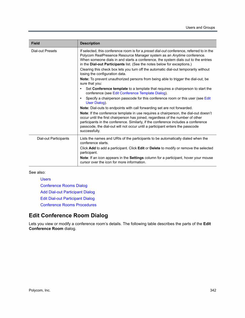
Users and Groups
Polycom, Inc. 342
See also:
Users
Conference Rooms Dialog
Add Dial-out Participant Dialog
Edit Dial-out Participant Dialog
Conference Rooms Procedures
Edit Conference Room DialogLets you view or modify a conference room’s details. The following table describes the parts of the Edit Conference Room dialog.
Dial-out Presets If selected, this conference room is for a preset dial-out conference, referred to in the Polycom RealPresence Resource Manager system as an Anytime conference. When someone dials in and starts a conference, the system dials out to the entries in the Dial-out Participants list. (See the notes below for exceptions.)
Clearing this check box lets you turn off the automatic dial-out temporarily without losing the configuration data.
Note: To prevent unauthorized persons from being able to trigger the dial-out, be sure that you:
• Set Conference template to a template that requires a chairperson to start the conference (see Edit Conference Template Dialog).
• Specify a chairperson passcode for this conference room or this user (see Edit User Dialog).
Note: Dial-outs to endpoints with call forwarding set are not forwarded.
Note: If the conference template in use requires a chairperson, the dial-out doesn’t occur until the first chairperson has joined, regardless of the number of other participants in the conference. Similarly, if the conference includes a conference passcode, the dial-out will not occur until a participant enters the passcode successfully.
Dial-out Participants Lists the names and URIs of the participants to be automatically dialed when the conference starts.
Click Add to add a participant. Click Edit or Delete to modify or remove the selected participant.
Note: If an icon appears in the Settings column for a participant, hover your mouse cursor over the icon for more information.
Field Description
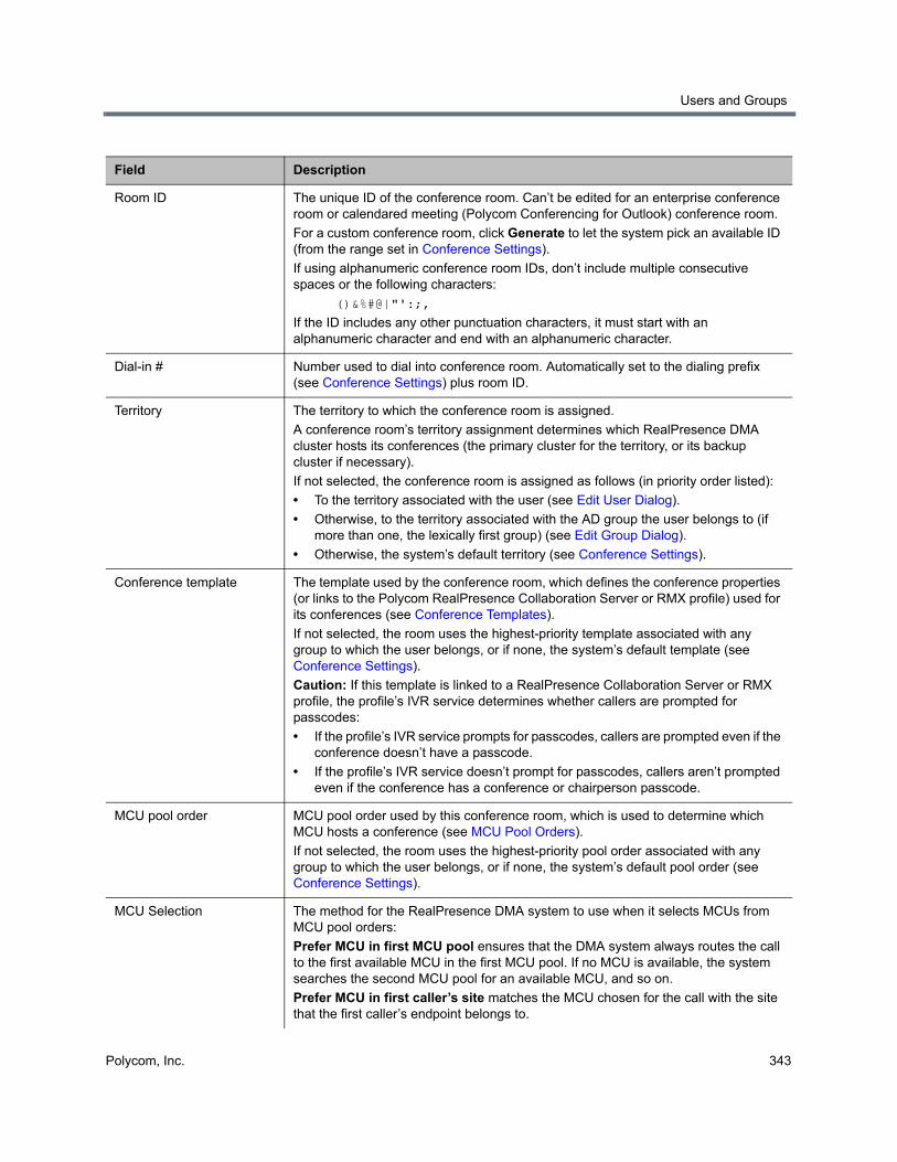
Users and Groups
Polycom, Inc. 343
Field Description
Room ID The unique ID of the conference room. Can’t be edited for an enterprise conference room or calendared meeting (Polycom Conferencing for Outlook) conference room.
For a custom conference room, click Generate to let the system pick an available ID (from the range set in Conference Settings).
If using alphanumeric conference room IDs, don’t include multiple consecutive spaces or the following characters:
()&%#@|"':;,
If the ID includes any other punctuation characters, it must start with an alphanumeric character and end with an alphanumeric character.
Dial-in # Number used to dial into conference room. Automatically set to the dialing prefix (see Conference Settings) plus room ID.
Territory The territory to which the conference room is assigned.
A conference room’s territory assignment determines which RealPresence DMA cluster hosts its conferences (the primary cluster for the territory, or its backup cluster if necessary).
If not selected, the conference room is assigned as follows (in priority order listed):
• To the territory associated with the user (see Edit User Dialog).
• Otherwise, to the territory associated with the AD group the user belongs to (if more than one, the lexically first group) (see Edit Group Dialog).
• Otherwise, the system’s default territory (see Conference Settings).
Conference template The template used by the conference room, which defines the conference properties (or links to the Polycom RealPresence Collaboration Server or RMX profile) used for its conferences (see Conference Templates).
If not selected, the room uses the highest-priority template associated with any group to which the user belongs, or if none, the system’s default template (see Conference Settings).
Caution: If this template is linked to a RealPresence Collaboration Server or RMX profile, the profile’s IVR service determines whether callers are prompted for passcodes:
• If the profile’s IVR service prompts for passcodes, callers are prompted even if the conference doesn’t have a passcode.
• If the profile’s IVR service doesn’t prompt for passcodes, callers aren’t prompted even if the conference has a conference or chairperson passcode.
MCU pool order MCU pool order used by this conference room, which is used to determine which MCU hosts a conference (see MCU Pool Orders).
If not selected, the room uses the highest-priority pool order associated with any group to which the user belongs, or if none, the system’s default pool order (see Conference Settings).
MCU Selection The method for the RealPresence DMA system to use when it selects MCUs from MCU pool orders:
Prefer MCU in first MCU pool ensures that the DMA system always routes the call to the first available MCU in the first MCU pool. If no MCU is available, the system searches the second MCU pool for an available MCU, and so on.
Prefer MCU in first caller’s site matches the MCU chosen for the call with the site that the first caller’s endpoint belongs to.
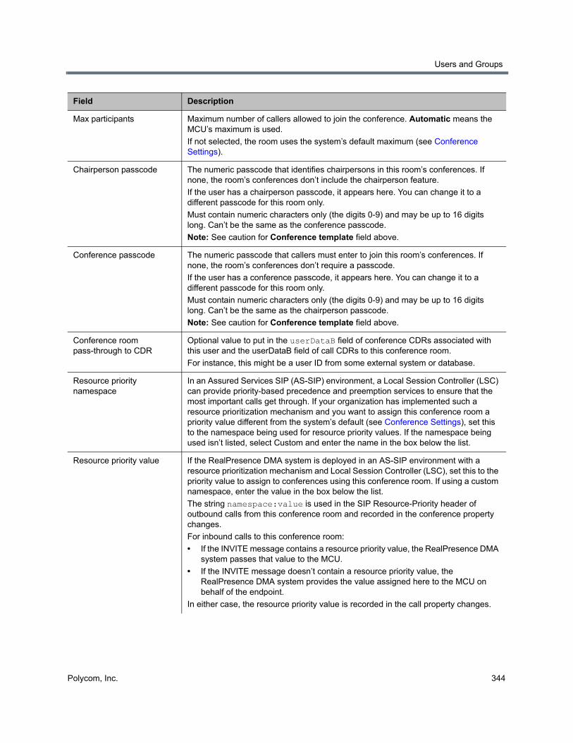
Users and Groups
Polycom, Inc. 344
Max participants Maximum number of callers allowed to join the conference. Automatic means the MCU’s maximum is used.
If not selected, the room uses the system’s default maximum (see Conference Settings).
Chairperson passcode The numeric passcode that identifies chairpersons in this room’s conferences. If none, the room’s conferences don’t include the chairperson feature.
If the user has a chairperson passcode, it appears here. You can change it to a different passcode for this room only.
Must contain numeric characters only (the digits 0-9) and may be up to 16 digits long. Can’t be the same as the conference passcode.
Note: See caution for Conference template field above.
Conference passcode The numeric passcode that callers must enter to join this room’s conferences. If none, the room’s conferences don’t require a passcode.
If the user has a conference passcode, it appears here. You can change it to a different passcode for this room only.
Must contain numeric characters only (the digits 0-9) and may be up to 16 digits long. Can’t be the same as the chairperson passcode.
Note: See caution for Conference template field above.
Conference room pass-through to CDR
Optional value to put in the userDataB field of conference CDRs associated with this user and the userDataB field of call CDRs to this conference room.
For instance, this might be a user ID from some external system or database.
Resource priority namespace
In an Assured Services SIP (AS-SIP) environment, a Local Session Controller (LSC) can provide priority-based precedence and preemption services to ensure that the most important calls get through. If your organization has implemented such a resource prioritization mechanism and you want to assign this conference room a priority value different from the system’s default (see Conference Settings), set this to the namespace being used for resource priority values. If the namespace being used isn’t listed, select Custom and enter the name in the box below the list.
Resource priority value If the RealPresence DMA system is deployed in an AS-SIP environment with a resource prioritization mechanism and Local Session Controller (LSC), set this to the priority value to assign to conferences using this conference room. If using a custom namespace, enter the value in the box below the list.
The string namespace:value is used in the SIP Resource-Priority header of outbound calls from this conference room and recorded in the conference property changes.
For inbound calls to this conference room:
• If the INVITE message contains a resource priority value, the RealPresence DMA system passes that value to the MCU.
• If the INVITE message doesn’t contain a resource priority value, the RealPresence DMA system provides the value assigned here to the MCU on behalf of the endpoint.
In either case, the resource priority value is recorded in the call property changes.
Field Description

Users and Groups
Polycom, Inc. 345
Presence In a Microsoft® Lync 2013 environment, you can configure presence publishing (the publishing of VMR status to a Lync 2013 client contact list) for each VMR. Enable this check box to override the system-wide default presence publishing settings defined on the Admin > Conference Manager > Conference Settings page.
Note: This property is visible only if the Publish presence for Polycom conference contacts check box is enabled on the Admin > Conference Manager > Conference Settings page.
Depending on the settings of the Publish presence for Polycom conference contacts and Create Polycom conference contacts check boxes on the Admin > Conference Manager > Conference Settings page, there are two modes of operation for this field:
• When Publish presence for Polycom conference contacts is checked and Create Polycom conference contacts is unchecked, the following options are displayed: Publish presence Do not publish presence
These options control whether the RealPresence DMA system will publish presence status for this Polycom conference contact.
• When both Publish presence for Polycom conference contacts and Create Polycom conference contacts are checked, the following options are displayed: Create contact and publish presence Do not create contact or publish presence
These options control whether the RealPresence DMA system will create an Active Directory contact resource for and publish presence for this Polycom conference contact.
Conference Duration Maximum duration of a conference (in hours and minutes) or Unlimited (the maximum in this case depends on the MCU).
If not selected, the room uses the longest duration associated with any group to which the user belongs, or if none, the system’s default maximum duration. See Conference Settings.
Calendar Event This section appears only for calendared meeting (Polycom Conferencing for Outlook) conference rooms. It shows the following (read-only):
• Start time and date (from the meeting invitation).
• Expiration date. The conference room is deleted from the system after this date.
Field Description
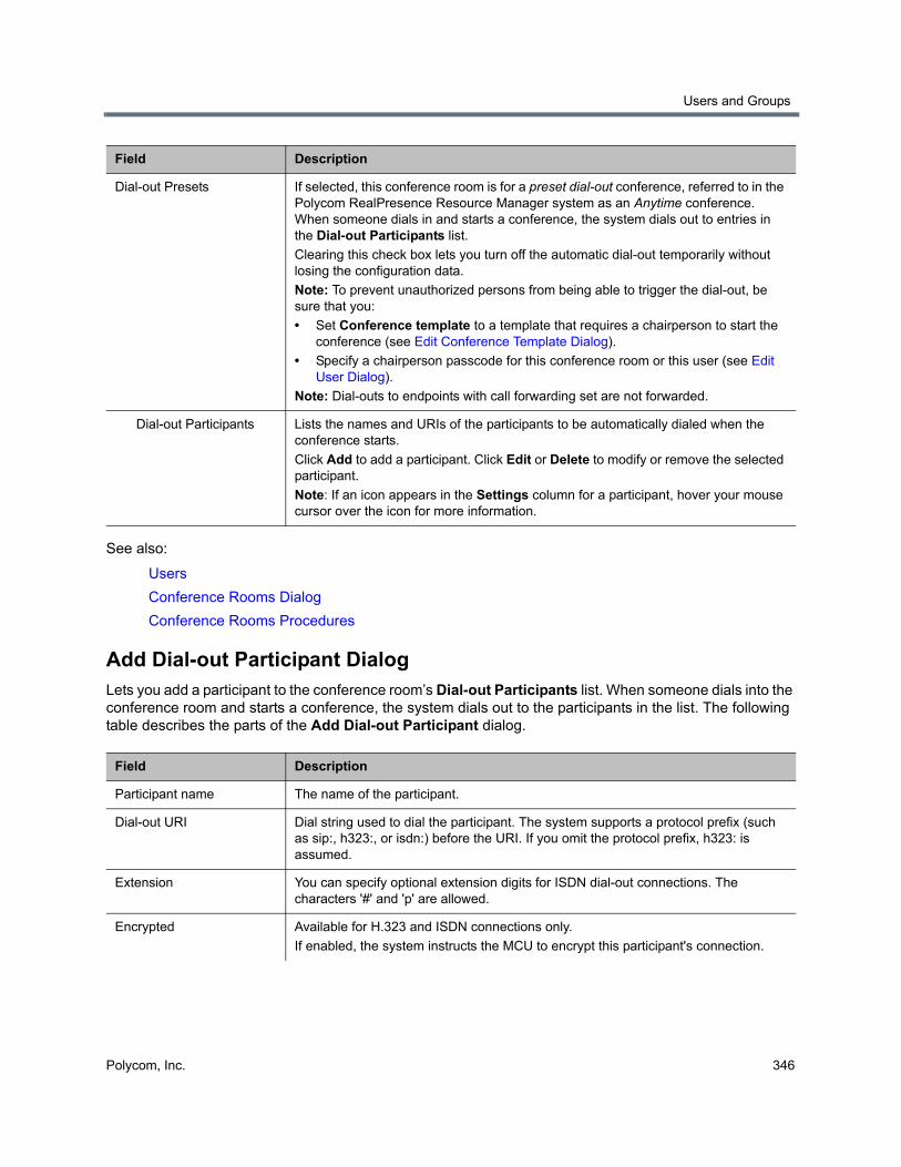
Users and Groups
Polycom, Inc. 346
See also:
Users
Conference Rooms Dialog
Conference Rooms Procedures
Add Dial-out Participant DialogLets you add a participant to the conference room’s Dial-out Participants list. When someone dials into the conference room and starts a conference, the system dials out to the participants in the list. The following table describes the parts of the Add Dial-out Participant dialog.
Dial-out Presets If selected, this conference room is for a preset dial-out conference, referred to in the Polycom RealPresence Resource Manager system as an Anytime conference. When someone dials in and starts a conference, the system dials out to entries in the Dial-out Participants list.
Clearing this check box lets you turn off the automatic dial-out temporarily without losing the configuration data.
Note: To prevent unauthorized persons from being able to trigger the dial-out, be sure that you:
• Set Conference template to a template that requires a chairperson to start the conference (see Edit Conference Template Dialog).
• Specify a chairperson passcode for this conference room or this user (see Edit User Dialog).
Note: Dial-outs to endpoints with call forwarding set are not forwarded.
Dial-out Participants Lists the names and URIs of the participants to be automatically dialed when the conference starts.
Click Add to add a participant. Click Edit or Delete to modify or remove the selected participant.
Note: If an icon appears in the Settings column for a participant, hover your mouse cursor over the icon for more information.
Field Description
Participant name The name of the participant.
Dial-out URI Dial string used to dial the participant. The system supports a protocol prefix (such as sip:, h323:, or isdn:) before the URI. If you omit the protocol prefix, h323: is assumed.
Extension You can specify optional extension digits for ISDN dial-out connections. The characters '#' and 'p' are allowed.
Encrypted Available for H.323 and ISDN connections only.
If enabled, the system instructs the MCU to encrypt this participant's connection.
Field Description

Users and Groups
Polycom, Inc. 347
See also:
Add Conference Room Dialog
Edit Conference Room Dialog
Edit Dial-out Participant DialogLets you edit a participant in the conference room’s Dial-out Participants list, changing the name or dial string for the participant. When someone dials into the conference room and starts a conference, the system dials out to the participants in the list. The following table describes the parts of the Edit Dial-out Participant dialog.
Audio-only Available for H.323 and ISDN connections only.
If enabled, the system instructs the MCU to use an audio-only connection for this participant.
Auto disconnect Available for H.323 and ISDN connections only.
Any dial-out participants you mark as Auto-disconnect are automatically disconnected once they are the only participants left in the conference. After they are disconnected, the conference ends.
You can use this feature to prevent MCU-to-MCU dial-outs from remaining open after the conference has ended.
Field Description
Participant name The name of the participant.
Dial-out URI Dial string used to dial the participant. The system supports a protocol prefix (such as sip:, h323:, or isdn:) before the URI. If you omit the protocol prefix, h323: is assumed.
Extension You can specify optional extension digits for ISDN dial-out connections. The characters '#' and 'p' are allowed.
Encrypted Available for H.323 and ISDN connections only.
If enabled, the system instructs the MCU to encrypt this participant's connection.
Audio-only Available for H.323 and ISDN connections only.
If enabled, the system instructs the MCU to use an audio-only connection for this participant.
Auto disconnect Available for H.323 and ISDN connections only.
Any dial-out participants you mark as Auto-disconnect are automatically disconnected once they are the only participants left in the conference. After they are disconnected, the conference ends.
You can use this feature to prevent MCU-to-MCU dial-outs from remaining open after the conference has ended.
Field Description
Users and Groups
Polycom, Inc. 348
See also:
Add Conference Room Dialog
Edit Conference Room Dialog
Users Procedures
To remove the default admin account and create a local account for yourself with administrative privileges
1 Log in as admin and go to User > Users.
The Users page appears.
2 Create a local user account for yourself with the Administrator role. See To add a local user.
3 Log out and log back in using your new local account.
4 Go to Users > Users and delete the admin account. See To delete a local user.
To find a user or users
1 Go to User > Users.
The Users page appears.
2 For a simple search, enter a search string in the Search users field and press ENTER.
The system matches the string you enter against the beginning of the user ID, first name, and last name. If you enter “sa” it displays users whose IDs or first or last names begin with “sa.” To search for a string not at the beginning of the field, you can use an asterisk (*) as a wildcard. You can restrict the search to local users by selecting the check box.
3 For more search options, click the down arrow to the right.
Additional controls appear that let you search specific fields and use specific filters.
4 Select the filters you want, enter search strings for one or more fields, and click Search.
The system displays the users matching your search criteria.
To add a local user
1 Go to User > Users.
2 In the Actions list, click Add.
3 In the Add User dialog, complete the General Info fields. See Add User Dialog.
4 To create the new user account, but not activate it immediately, select Account Disabled.
Caution: Remove the default admin account
To eliminate a serious security risk, perform the first procedure below as soon as possible after installing your system.
Note: Search results could be unsorted
The RealPresence DMA system’s user database is unsorted. To avoid performance issues, if your query matches more than 4000 users, no attempt is made to sort the results on the server side before returning the matching records.
Users and Groups
Polycom, Inc. 349
5 To assign the user additional roles (besides Conferencing User), click Roles. Select the role or roles you want to assign and use the arrow button to move them to the Selected Roles list.
Explicitly assigned roles give the user access to the system management interface.
6 Click OK.
To edit a user
1 Go to User > Users.
2 If necessary, filter the Users list to find the user to be modified.
3 Select the user and click Edit.
4 As required, edit the General Info, Roles, and Conference Passcodes sections of the User Properties dialog. See Edit User Dialog.
For enterprise users, you can change their roles and their chairperson and conference passcodes, and you can enable or disable their accounts, but you can’t change user names, user IDs, or user passwords.
For local users, you can change everything but the user ID. In maximum security mode, changing a user’s password requires you to authenticate yourself by entering your password when prompted.
5 Click OK.
To delete a local user
1 Go to User > Users.
2 If necessary, filter the Users list to find the user to be deleted.
You can only delete local users, not users added from the Active Directory.
3 Select the user and click Delete User.
4 In the Delete User dialog, click Yes.
The user is deleted from the Polycom RealPresence DMA system.
See also:
User Roles Overview
Adding Users Overview
Users
Add User Dialog
Edit User Dialog
Conference Rooms Procedures
To add a conference room to a user
1 Go to User > Users and select the user to whom you want to add a room.
2 In the Actions list, click Manage Conf Rooms.
The Conference Rooms dialog appears.
Users and Groups
Polycom, Inc. 350
3 Click Add.
The Add Conference Room dialog appears.
4 Complete the settings for the new conference room. See Add Conference Room Dialog.
5 To set up this conference room for a preset dial-out conference (also known as an Anytime conference), select Dial-out Presets and do the following:
a Ensure that this room or user has a chairperson passcode and that you’ve selected a conference template that’s linked to a Polycom RealPresence Collaboration Server or RMX conference IVR service and requires a chairperson to start the conference.
b To link this preset conference to an external audio conferencing bridge (for hosting audio-only participants), in the Digits field enter the E.164 number for connecting to that bridge, and in the IVR DTMF field enter any DTMF digits (such as an access code or PIN) to send to the audio conferencing bridge after connecting (use p to specify a pause).
This capability requires a Polycom MCU with ISDN service.
c Under Dial-out Participants, add the participants to be called when the conference starts.
6 Click OK.
To edit one of a user’s conference rooms
1 Go to User > Users and select the user whose conference room you want to edit.
2 In the Actions list, click Manage Conf Rooms.
The Conference Rooms dialog appears.
3 Select the conference room you want to edit and click Edit.
The Edit Conference Room dialog appears.
4 Modify the settings you want to change. See Edit Conference Room Dialog.
5 To set up this conference room for a preset dial-out conference (also known as anytime conference), select Dial-out Presets and do the following:
a Ensure that this room or user has a chairperson passcode and that you’ve selected a conference template that’s linked to a Polycom RealPresence Collaboration Server or RMX conference IVR service and requires a chairperson to start the conference.
b To link this preset conference to an external audio conferencing bridge, in the Digits field enter the E.164 number for connecting to that bridge, and in the IVR DTMF field enter any DTMF digits (such as an access code or PIN) to send to the audio conferencing bridge after connecting (use p to specify a pause).
This capability requires a Polycom MCU with ISDN service.
c Under Dial-out Participants, add the participants to be called when the conference starts.
6 To turn of automatic dial-out temporarily without losing the configuration data, clear the Dial-out Presets check box.
7 Click OK.
To delete one of a user’s custom conference rooms
1 Go to User > Users and select the user whose custom conference room you want to delete.
2 In the Actions list, click Manage Conf Rooms.
The Conference Rooms dialog appears.
Users and Groups
Polycom, Inc. 351
3 Select the conference room you want to remove and click Delete.
You can’t delete an enterprise conference room or a conference room created by the system for a calendared meeting.
4 When prompted to confirm, click Yes.
See also:
Users
Conference Rooms Dialog
Add Conference Room Dialog
Edit Conference Room Dialog
Users Procedures
GroupsGroups functionality is available only if your Polycom RealPresence DMA system is integrated with an Active Directory. User groups are defined in your Active Directory and imported into the Polycom RealPresence DMA system from there.
The Groups page provides access to information about enterprise groups. From it, you can:
● Import enterprise groups.
● Specify Polycom RealPresence DMA system roles to be assigned to members of a group.
● Specify a conference template and MCU pool order to be used for a group.
The following table describes the fields on the Groups page.
Note: Enterprise vs. local users
You must be an enterprise user (with the appropriate user role assignments) to see and work with enterprise users. A local user can only see other local users, regardless of user roles.
Microsoft Active Directory provides two group types and four group scopes. The Polycom RealPresence DMA system supports only security groups (not distribution groups) with universal or global scope.
Field Description
Group Name Name of the group, as defined in the Active Directory.
Description Description from the Active Directory.
Domain Name of the domain to which the group belongs.
Class of service Class of service assigned to the group, which determines the priority of the group’s calls.
If none, the group receives the system’s default class of service. See Conference Settings.
Note: A class of service may also be assigned to a user (see Users) or an endpoint (see Endpoints).
Note: The class of service of the device applies to point to point calls. VMR calls use the class of service of the conference room.
Users and Groups
Polycom, Inc. 352
See also:
Users
Edit Group Dialog
Enterprise Groups Procedures
Import Enterprise Groups DialogThe following table describes the fields in the Import Enterprise Groups dialog.
Conference Template Template assigned to the group, if any, which defines the conference properties (or links to the Polycom MCU conference profile) used for its conferences. See Conference Templates.
The template assignment can be made at the conference room, AD group, or system default level.
MCU Pool Order MCU pool order assigned to this group, if any, which is used to determine which MCU hosts a conference. See MCU Pool Orders.
The pool order assignment can be made at the conference room, AD group, or system default level.
Territory Territory to which the group’s conference rooms (virtual meeting rooms, or VMRs) are assigned.
A conference room’s territory assignment determines which RealPresence DMA cluster hosts the conference (the primary cluster for the territory, or its backup cluster if necessary). The assignment can be made at the conference room level, the user level, the AD group level, or the system default level.
Assigned Roles RealPresence DMA system roles, if any, that are automatically assigned to members of this group (all users automatically have the Conferencing User role; it’s not listed or explicitly assigned). See User Roles Overview.
Field Description
Search domain Optionally, select a domain to search.
Group To find all groups, leave blank. To find groups beginning with a specific letter or letters, enter the string. Then click Search.
You can use a wildcard (*) for more complex searches, such as:
• s*admins
• *eng*
Search results Lists the security groups in your Active Directory that match the search string.
The system only retrieves the first 1000 groups found. If the count shows 1000, you may need to refine your search criteria.
Groups to import Lists the groups you’ve selected for import, using the arrows to move them from the Search results box.
Field Description
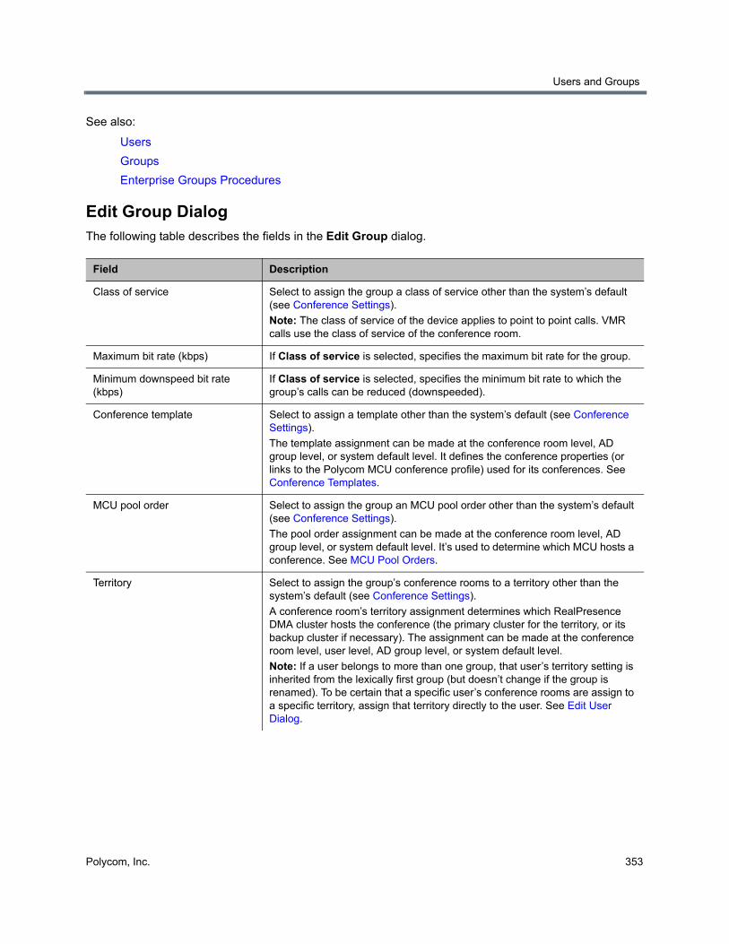
Users and Groups
Polycom, Inc. 353
See also:
Users
Groups
Enterprise Groups Procedures
Edit Group DialogThe following table describes the fields in the Edit Group dialog.
Field Description
Class of service Select to assign the group a class of service other than the system’s default (see Conference Settings).
Note: The class of service of the device applies to point to point calls. VMR calls use the class of service of the conference room.
Maximum bit rate (kbps) If Class of service is selected, specifies the maximum bit rate for the group.
Minimum downspeed bit rate (kbps)
If Class of service is selected, specifies the minimum bit rate to which the group’s calls can be reduced (downspeeded).
Conference template Select to assign a template other than the system’s default (see Conference Settings).
The template assignment can be made at the conference room level, AD group level, or system default level. It defines the conference properties (or links to the Polycom MCU conference profile) used for its conferences. See Conference Templates.
MCU pool order Select to assign the group an MCU pool order other than the system’s default (see Conference Settings).
The pool order assignment can be made at the conference room level, AD group level, or system default level. It’s used to determine which MCU hosts a conference. See MCU Pool Orders.
Territory Select to assign the group’s conference rooms to a territory other than the system’s default (see Conference Settings).
A conference room’s territory assignment determines which RealPresence DMA cluster hosts the conference (the primary cluster for the territory, or its backup cluster if necessary). The assignment can be made at the conference room level, user level, AD group level, or system default level.
Note: If a user belongs to more than one group, that user’s territory setting is inherited from the lexically first group (but doesn’t change if the group is renamed). To be certain that a specific user’s conference rooms are assign to a specific territory, assign that territory directly to the user. See Edit User Dialog.
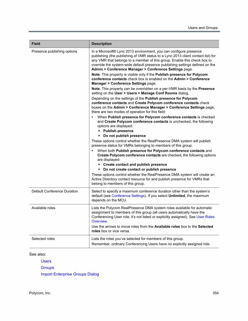
Users and Groups
Polycom, Inc. 354
See also:
Users
Groups
Import Enterprise Groups Dialog
Presence publishing options In a Microsoft® Lync 2013 environment, you can configure presence publishing (the publishing of VMR status to a Lync 2013 client contact list) for any VMR that belongs to a member of this group. Enable this check box to override the system-wide default presence publishing settings defined on the Admin > Conference Manager > Conference Settings page.
Note: This property is visible only if the Publish presence for Polycom conference contacts check box is enabled on the Admin > Conference Manager > Conference Settings page.
Note: This property can be overridden on a per-VMR basis by the Presence setting on the User > Users > Manage Conf Rooms dialog.
Depending on the settings of the Publish presence for Polycom conference contacts and Create Polycom conference contacts check boxes on the Admin > Conference Manager > Conference Settings page, there are two modes of operation for this field:
• When Publish presence for Polycom conference contacts is checked and Create Polycom conference contacts is unchecked, the following options are displayed: Publish presence Do not publish presence
These options control whether the RealPresence DMA system will publish presence status for VMRs belonging to members of this group.
• When both Publish presence for Polycom conference contacts and Create Polycom conference contacts are checked, the following options are displayed: Create contact and publish presence Do not create contact or publish presence
These options control whether the RealPresence DMA system will create an Active Directory contact resource for and publish presence for VMRs that belong to members of this group.
Default Conference Duration Select to specify a maximum conference duration other than the system’s default (see Conference Settings). If you select Unlimited, the maximum depends on the MCU.
Available roles Lists the Polycom RealPresence DMA system roles available for automatic assignment to members of this group (all users automatically have the Conferencing User role; it’s not listed or explicitly assigned). See User Roles Overview.
Use the arrows to move roles from the Available roles box to the Selected roles box or vice versa.
Selected roles Lists the roles you’ve selected for members of this group.
Remember, ordinary Conferencing Users have no explicitly assigned role.
Field Description
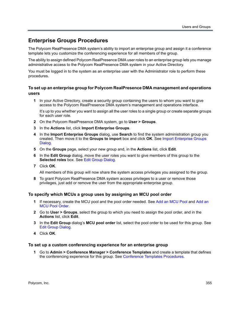
Users and Groups
Polycom, Inc. 355
Enterprise Groups ProceduresThe Polycom RealPresence DMA system’s ability to import an enterprise group and assign it a conference template lets you customize the conferencing experience for all members of the group.
The ability to assign defined Polycom RealPresence DMA user roles to an enterprise group lets you manage administrative access to the Polycom RealPresence DMA system in your Active Directory.
You must be logged in to the system as an enterprise user with the Administrator role to perform these procedures.
To set up an enterprise group for Polycom RealPresence DMA management and operations users
1 In your Active Directory, create a security group containing the users to whom you want to give access to the Polycom RealPresence DMA system’s management and operations interface.
It’s up to you whether you want to assign all the user roles to a single group or create separate groups for each user role.
2 On the Polycom RealPresence DMA system, go to User > Groups.
3 In the Actions list, click Import Enterprise Groups.
4 In the Import Enterprise Groups dialog, use Search to find the system administration group you created. Then move it to the Groups to import box and click OK. See Import Enterprise Groups Dialog.
5 On the Groups page, select your new group and, in the Actions list, click Edit.
6 In the Edit Group dialog, move the user roles you want to give members of this group to the Selected roles box. See Edit Group Dialog.
7 Click OK.
All members of this group will now share the system access privileges you assigned to the group.
8 To grant Polycom RealPresence DMA system access privileges to a user or remove those privileges, just add or remove the user from the appropriate enterprise group.
To specify which MCUs a group uses by assigning an MCU pool order
1 If necessary, create the MCU pool and the pool order needed. See Add an MCU Pool and Add an MCU Pool Order.
2 Go to User > Groups, select the group to which you need to assign the pool order, and in the Actions list, click Edit.
3 In the Edit Group dialog’s MCU pool order list, select the pool order to be used for this group. See Edit Group Dialog.
4 Click OK.
To set up a custom conferencing experience for an enterprise group
1 Go to Admin > Conference Manager > Conference Templates and create a template that defines the conferencing experience for this group. See Conference Templates Procedures.
Users and Groups
Polycom, Inc. 356
2 Optionally, in the Actions list, click Move Up until your new conference template has Priority 1.
This ensures that users who have access to multiple conference templates will use this one for their enterprise conference room. You can choose a different priority level, but then some members of the group for which you created the template may end up using a higher-ranking template.
3 Go to User > Groups, select the group for which you created the template, and in the Actions list, click Edit.
4 In the Edit Group dialog’s Conference template list, select the template you created for this group. See Edit Group Dialog.
5 Click OK.
See also:
Users
Groups
Import Enterprise Groups Dialog
Edit Group Dialog
Login SessionsThe Login Sessions page displays information about the currently active user login sessions and enables you to terminate a login session. You must be an Administrator user to terminate a login session.
The following table describes the parts of the Login Sessions list.
To terminate a user’s login session
1 In the Login Sessions list, select the login session you want to terminate.
2 In the Actions list, click Terminate Session.
A dialog asks you to confirm.
3 Click Yes.
The system terminates the session immediately. The terminated user is informed that the connection to the server was lost.
Note: Session termination and maximum security mode
Session termination is not supported in Maximum security mode.
Column Description
Domain The domain to which the user belongs.
User ID The user’s login name.
Host Address The IP address from which the user logged in.
Node Name The Polycom RealPresence DMA system server on which the user logged in.
Creation Time The time and date when the user logged in.
Users and Groups
Polycom, Inc. 357
See also:
Session
Users and Groups
Change Password DialogThe system may be configured to expire local user passwords after a certain number of days (see Local Password). If your password has expired when you try to log into the system, the Change Password dialog prompts you for a new password.
You can change your password at other times by going to User > Change Passwords (but not more often than specified on the Local Password page).
The following table describes the fields in the dialog.
See also:
Security Settings
Users and Groups
Field Description
User ID The user name with which you’re logging in. Display only.
Old password For security reasons, you must re-enter your old password.
New password Enter a new password. The password must satisfy the local password rules specified for the system (see Local Password).
Confirm new password Retype the password to confirm that you entered it correctly.
Polycom, Inc. 358
System Management and Maintenance
This section describes the following Polycom® RealPresence® Distributed Media Application™ (DMA®) 7000 system operations topics:
● Management and Maintenance Overview
● Recommended Regular Maintenance
● Dashboard
● Alerts
● System Log Files
● Troubleshooting Utilities
● Diagnostics for your Polycom Server
● Backing Up and Restoring
● Upgrading the Software
● Adding a Second Server
● Replacing a Failed Server
● Shutting Down and Restarting
Management and Maintenance OverviewThe Polycom RealPresence DMA system requires relatively little ongoing maintenance beyond monitoring the status of the system and downloading backups and other data you want to archive. All system management and maintenance tasks can be performed in the management interface. See the appropriate topic for your user role:
● Administrator Responsibilities
● Auditor Responsibilities
● Provisioner Responsibilities
Administrator ResponsibilitiesAs a Polycom RealPresence DMA system administrator, you’re responsible for the installation and ongoing maintenance of the system. You should be familiar with the following configurations, tasks, and operations:
● Installing licenses when the system is first installed and when additional call capacity is added. See Licenses.
● Monitoring system health and performing the recommended regular maintenance. See Recommended Regular Maintenance.
System Management and Maintenance
Polycom, Inc. 359
● Using the system tools provided to aid with system and network diagnostics, monitoring, and troubleshooting. See Troubleshooting Utilities. Should the need arise, Polycom Global Services personnel may ask you to run these tools.
● Upgrading the system when upgrades/patches are made available. See Upgrading the Software.
Administrative Best PracticesThe following are some of our recommendations for administrative best practices:
● Perform the recommended regular maintenance.
● Except in emergencies or when instructed to by Polycom Global Services personnel, don’t reconfigure, install an upgrade, or restore a backup when there are active calls and conferences on the system. Many of these operations will require a system restart to complete, which will result in these calls and conferences being dropped. Before performing these operations, busy out all MCUs and wait for all conferencing activity to cease.
● Before you reconfigure, install an upgrade, or restore a backup, manually create a new backup. Then download and archive this backup in the event that something unforeseen occurs and it becomes necessary to restore the system to a known good state.
● For proper name resolution and smooth network operations, configure two or more DNS servers in your network configuration (see Network Settings). This allows the Polycom RealPresence DMA system to function properly in the event of a single external DNS failure.
● Configure at least one NTP server in your time configuration (see Time Settings) and preferably three. Proper time management helps ensure that your cluster operates efficiently and helps in diagnosing any issues that may arise in the future. Proper system time is also essential for accurate audit and CDR data.
● Unless otherwise instructed by Polycom Global Services, always use the High Security setting. See Security Settings.
Auditor ResponsibilitiesAs a Polycom RealPresence DMA system auditor, you’re responsible for managing the system’s logging and history retention. You should be familiar with the following configurations and operations:
● Configuring logging for the system. See Configure Logging Settings. These settings affect the number and the contents of the log archives available for download from the system. See System Log Files. Polycom Global Services personnel may ask you to adjust the logging configuration and/or download and send them logs.
● Configuring history retention levels for the system. See History Retention Settings. These settings affect how much system activity history is retained on the system and available for download as CDRs. See Call History, Conference History, and Call Detail Records (CDRs).
Auditor Best PracticesThe following are some of our recommendations for auditing best practices:
Note: System maintenance tasks can be delegated
You can delegate some of the maintenance tasks to a provisioner. See Provisioner Responsibilities.
System Management and Maintenance
Polycom, Inc. 360
● Unless otherwise instructed by Polycom Global Services, configure logging at the debug level with a rolling frequency of every day and a retention period of 60 days. If hard drive space becomes an issue, decrease the retention period incrementally until the disk space issue is resolved.
● Download log archives regularly and back them up securely (preferably offsite as well as onsite). Delete downloaded log archives to free up disk space.
● Export CDRs regularly and back them up securely (preferably offsite as well as onsite).
Provisioner ResponsibilitiesAs a Polycom RealPresence DMA system provisioner, you have access to many of the same features and functions as the system administrator (see Polycom RealPresence DMA System User Roles and Their Access Privileges). Your responsibilities depend on your organization’s policies and the tasks delegated to you by the system administrator. For instance, you may be delegated responsibility for some of the following:
● Managing and monitoring users’ conference rooms. See Users.
● Managing and monitoring registered endpoints. See Endpoints.
● Monitoring active calls. See Active Calls.
● Monitoring system health and network usage. See General system health and capacity checks.
● Monitoring call, conference, and registration history. See Call History, Conference History, and Registration History Report.
● Downloading network usage data at the appropriate intervals. See Network usage data export and Exporting Network Usage Data.
● Downloading detailed call and conference history data at the appropriate intervals. See CDR export and Call Detail Records (CDRs).
Recommended Regular MaintenancePerform the following tasks to keep your Polycom RealPresence DMA system operating trouble-free and at peak efficiency. These tasks can be done quickly and should be run at least weekly.
Regular archive of backupsLog into the Polycom RealPresence DMA system, go to Maintenance > Backup and Restore, and check for new backups. If there are new backups, download and archive the latest one. Delete backups after downloading in order to free up disk space.
Every night, each Polycom RealPresence DMA system cluster determines whether its configuration or local user data have changed. If so, it creates a configuration-only backup of the system. For details on backups, see Backing Up and Restoring.
General system health and capacity checksOn the Dashboard (see Dashboard), verify that:
● There are no alerts indicating problems with any part of the system.
● The Supercluster Status pane shows the correct number of servers and clusters, and the network interfaces that should be working (depending on your IP type and split network settings) are up (green up arrow) and in full duplex mode, with the speed correct for your enterprise network.
System Management and Maintenance
Polycom, Inc. 361
● The Cluster Info pane’s Resources section shows that there is adequate free disk space. If the system is using more than 80% of disk space, free up space by doing some or all of the following:
Go to Maintenance > Backup and Restore and download and delete backup files (see Backing Up and Restoring).
Go to Maintenance > System Log Files and download and delete log file archives (you must have the Auditor role to do so; see System Log Files).
Go to Admin > Local Cluster > Logging Settings and reducing the retention period for log archives (see Configure Logging Settings).
Go to Admin > Call Server > History Retention Settings and reduce the retention values (you must have the Auditor role to do so; see History Retention Settings).
● The Territories Status pane shows that all territories have the correct capabilities, are being managed by their primary cluster, and (if your deployment is so configured), have a backup cluster.
Go to Reports > Network Usage (see Network Usage Report) and view the graph for each cluster with the following capacity-related metrics selected:
● Call Counts — If the number of concurrent calls approaches the license limit, you may need to rebalance territory responsibilities, add licensed capacity, or add another cluster.
● Conference Manager Calls — If the number of concurrent calls approaches the number of MCU ports available, you may need to add MCU capacity.
View the graph for each site, site link, and subnet with Calls Dropped and Calls Downspeeded selected. These metrics show only calls dropped or downspeeded due to insufficient bandwidth at the selected throttlepoint. Any values above zero are indicators of bandwidth saturation and suggest that it’s time to increase network bandwidth.
Microsoft Active Directory healthIf the Polycom RealPresence DMA system is integrated with an Active Directory, check the following (you must be logged in as an enterprise user):
● Reports > Microsoft Active Directory Integration (see Active Directory Integration Report). Check the status and results of the last cache update, and verify that membership information for imported groups, if any, was successfully loaded.
● Reports > Conference Room Errors (see Conference Room Errors Report). Check:
The total number of users and the number of users with conference room IDs. Make sure both are about what you would expect for your system (it may be helpful to keep records for comparison over time). Contact your Active Directory administrator if necessary.
The number of users with blank, invalid, or duplicate conference room IDs. These are enterprise users not properly provisioned for conferencing on the Polycom RealPresence DMA system. They’re listed below. Contact your Active Directory administrator to resolve issues with these users.
● Reports > Orphaned Groups and Users (see Orphaned Groups and Users Report). Verify that the number of orphans is not unexpectedly large.
● Reports > Enterprise Passcode Errors (see Enterprise Passcode Errors Report). If you’re assigning conference and/or chairperson passcodes to enterprise users, verify that the number of passcode errors is not unexpectedly large.

System Management and Maintenance
Polycom, Inc. 362
Security configurationGo to Admin > Local Cluster > Security Settings and verify that the security settings are what you expect (we strongly recommend always using the high security mode). Any departure from the settings you expected to see may indicate that your system has been compromised. See Security Settings.
CertificatesGo to Admin > Local Cluster > Certificates and verify that the list of certificates contains the certificates you’ve installed and looks as you would expect (an archived screen capture may be helpful for comparison).
Display the details for any certificate you’ve installed and verify they are as expected (again, an archived screen capture may be helpful for comparison).
Network usage data exportThe system stores up to approximately 1 GB of network usage data, deleting the oldest as needed. Data size is based on site topology complexity, not usage, so it’s very predictable. On a system with the largest supported site topology, it’s only one day’s worth of usage data, but most systems should retain data for a substantially longer period.
Determine an appropriate download interval for your site topology and download network usage data to your PC at that interval. See Exporting Network Usage Data.
CDR exportIf you want to preserve detailed call and conference history data in spreadsheet form off the Polycom RealPresence DMA system, periodically download the system’s CDR (call detail record) data to your PC. See Call Detail Records (CDRs).
DashboardWhen you log into the Polycom RealPresence DMA system, the system Dashboard appears. You can return to the Dashboard from any other page by clicking the (“home”) button to the left of the menus. Use the system Dashboard to view information about system health and activity levels.
The Dashboard is highly customizable. Initially, it contains six default panes. You can close any of these that you don’t want, and you can add others. You can add multiple copies of the same pane, each showing information for a different cluster. The maximum number of panes is 50.
Click the Add Panes button to see the panes that are available. In the Settings dialog (see Settings Dialog), you can specify the maximum number of columns for the Dashboard. Note that this is a maximum, not a fixed value. The panes have a minimum width, and they arrange themselves to best fit your browser window. Depending on the size of your browser window, there may be fewer columns than the maximum you select. For instance, at the minimum supported display resolution of 1280x1024, only two columns can be displayed.
The system remembers your Dashboard configuration, and you’ll see the same configuration when you log into any cluster of the supercluster.
The buttons on the right side of each pane’s title bar let you access help, go a related page (where appropriate), maximize the pane to fill the window, restore it to its normal size, or close the pane. Hover over a button to see what it does.
System Management and Maintenance
Polycom, Inc. 363
An alert icon appears in the title bar of a pane if there is an alert related to its information. Hover over it to see the alert message.
See also:
Active Directory Integration Pane
Call Server Active Calls Pane
Call Server Registrations Pane
Cluster Info Pane
Conference History – Max Participants Pane
Conference Manager MCUs Pane
Conference Manager Usage Pane
Exchange Server Integration Pane
Juniper Networks SRC Integration Pane
License Status Pane
RealPresence Resource Manager Integration Pane
Signaling Settings Pane
Supercluster Status Pane
Territory Status Pane
User Login History Pane
Active Directory Integration PaneDisplays information about the status of Active Directory integration. If the system is integrated with AD, this pane shows:
● The territory (and cluster) responsible for refreshing the cache.
● When the cache was last refreshed and by which server.
● The AD server address and user ID used.
● The number of enterprise conference rooms created.
Click the Link button to go to the Microsoft Active Directory page.
See also:
Dashboard
Call Server Active Calls PaneDisplays the current number of calls in total and for each cluster of the supercluster and the licensed call limit in total and for each cluster.
In a superclustered environment, a call may span multiple clusters. Each “leg” of such a call is counted on the cluster it’s on. The total for all clusters includes the total of all legs of cluster-spanning calls. Also, any confirmed ARQ request that originated from an MCU consumes a license on the cluster that confirms it.
If H.323 signaling is enabled, the call mode (direct or routed) is also shown.
Click a column heading to sort on that column. Click the Link button to go to the Active Calls page.
System Management and Maintenance
Polycom, Inc. 364
See also:
Dashboard
Call Server Registrations PaneDisplays the total number of active (including active quarantined) and inactive (including inactive quarantined and blocked) endpoint registrations and the number that failed in the past 24 hours. Hover over a registration number to see the limit.
Also displays the total number of registrations for each cluster of the supercluster. Hover over a cluster’s total to see the breakdown between active and inactive.
Click a column heading to sort on that column. Click the Link button to go to the Endpoints page.
See also:
Dashboard
Cluster Info PaneDisplays detailed information about the selected cluster. For a two-server cluster, the pane contains a tab for each server. The tab label indicates which server is currently active. Each tab contains the following information about the server:
● Current time and uptime
● Server, Proxias, and application software version numbers
● Hardware model and serial number
● Time source
● Management network MAC and IP addresses
● Signaling network MAC and IP addresses (if configured for split network)
● CPU usage percentage (all cores), as reported by Hyperic SIGAR
● Memory usage (hover over the bar chart to see details)
It’s normal for memory usage to be high.
● Swap space (total and free)
● Disk space usage (actual and percentage)
● Log space usage (actual and percentage) and next scheduled log purge
Click the Link button to go to the Logging Settings page.
See also:
Dashboard
Conference History – Max Participants PaneDisplays a bar graph showing variations in the maximum number of Conference Manager conference participants over the time span you select.
The graph shows the data for all Conference Manager clusters. The Ad-hoc participants category includes all dial-outs and all dial-ins to non-scheduled conferences. The Other participants category includes all
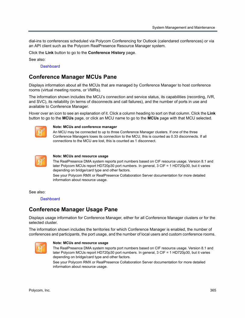
System Management and Maintenance
Polycom, Inc. 365
dial-ins to conferences scheduled via Polycom Conferencing for Outlook (calendared conferences) or via an API client such as the Polycom RealPresence Resource Manager system.
Click the Link button to go to the Conference History page.
See also:
Dashboard
Conference Manager MCUs PaneDisplays information about all the MCUs that are managed by Conference Manager to host conference rooms (virtual meeting rooms, or VMRs).
The information shown includes the MCU’s connection and service status, its capabilities (recording, IVR, and SVC), its reliability (in terms of disconnects and call failures), and the number of ports in use and available to Conference Manager.
Hover over an icon to see an explanation of it. Click a column heading to sort on that column. Click the Link button to go to the MCUs page, or click an MCU name to go to the MCUs page with that MCU selected.
See also:
Dashboard
Conference Manager Usage PaneDisplays usage information for Conference Manager, either for all Conference Manager clusters or for the selected cluster.
The information shown includes the territories for which Conference Manager is enabled, the number of conferences and participants, the port usage, and the number of local users and custom conference rooms.
Note: MCUs and conference manager
An MCU may be connected to up to three Conference Manager clusters. If one of the three Conference Managers loses its connection to the MCU, this is counted as 0.33 disconnects. If all connections to the MCU are lost, this is counted as 1 disconnect.
Note: MCUs and resource usage
The RealPresence DMA system reports port numbers based on CIF resource usage. Version 8.1 and later Polycom MCUs report HD720p30 port numbers. In general, 3 CIF = 1 HD720p30, but it varies depending on bridge/card type and other factors.
See your Polycom RMX or RealPresence Collaboration Server documentation for more detailed information about resource usage.

System Management and Maintenance
Polycom, Inc. 366
See also:
Dashboard
Exchange Server Integration PaneIf the Polycom RealPresence DMA system is integrated with a Microsoft Exchange server (see Microsoft Exchange Server Integration), displays the following:
● The server in the cluster performing Exchange server integration and integration status, which can be one of the following:
Unavailable — A service status or inter-server communication problem prevented determination of the integration status.
Error — The system was unable to establish a connection to the Exchange server. This could be a network or Exchange server problem, or it could be a login failure.
Awaiting Active Directory — The system isn’t integrated with the Active Directory, required for Exchange server integration.
Primary SMTP mailbox not found — The mailbox configured for the Polycom RealPresence DMA system isn’t in the system’s Active Directory cache.
Subscription pending — The Polycom RealPresence DMA system has asked the Exchange server to send it notifications and is waiting to receive its first notification to confirm that the Exchange server can communicate with the system. If this status persists for more than a minute or so, there is likely a configuration problem (such as an invalid certificate or the Exchange server is unable to resolve the RealPresence DMA system’s FQDN).
Exchange authentication failed — The credentials for the Polycom RealPresence DMA system’s mailbox are no longer valid (e.g., the password has expired).
OK — The Polycom RealPresence DMA system is receiving and processing Polycom Conferencing meeting notifications from the Exchange server.
● The territory configured for Exchange server integration, color-coded according to supercluster status.
● The host name or IP address for the Exchange server as entered on the Microsoft Exchange Server page.
● The Polycom RealPresence DMA system’s mailbox address.
● The number of Polycom Conferencing meetings today.
Click the Link button to go to the Microsoft Exchange Server page.
See also:
Dashboard
Juniper Networks SRC Integration Pane If the Polycom RealPresence DMA system is integrated with a Juniper Networks Service Resource Controller (see Juniper Networks SRC Integration), displays the following:
● The IP address or host name of the configured SRC server.
● The configured Server port.
● The configured Client ID.
● The configured Subscriber URI.
System Management and Maintenance
Polycom, Inc. 367
● The average request/response interval over the last ten interactions with the configured SRC server.
Click the Link button to go to the Juniper Networks SRC page.
See also:
Dashboard
License Status PaneDisplays the license status of the selected cluster and the number of licensed and active calls. Note that a call that has multiple “legs” (spans multiple clusters) uses a license for each leg of the call (each cluster it spans).
Click the Link button to go to the Licenses page (only available if the selected cluster is the one on which you’re logged in).
See also:
Dashboard
RealPresence Resource Manager Integration PaneIf the Polycom RealPresence DMA system is integrated with a Polycom RealPresence Resource Manager system (see RealPresence Resource Manager Integration), displays the following:
● Host name or IP address of the RealPresence Resource Manager system.
● User name used to log into the RealPresence Resource Manager system.
● Time when site topology data was last updated from the RealPresence Resource Manager system.
● Number of territories, sites, site links, and network (MPLS) clouds in the site topology data obtained from the RealPresence Resource Manager system.
Click the Link button to go to the RealPresence Resource Manager page.
See also:
Dashboard
Signaling Settings PaneDisplays the H.323, SIP. and WebRTC signaling settings for the selected cluster, including whether each is enabled and what ports are assigned.
Click the Link button to go to the Signaling Settings page.
See also:
Dashboard
Supercluster Status PaneDisplays the status of each server in every cluster of the supercluster, the status of its private, management, and signaling interfaces, and the territory for which it’s responsible. A territory is green if being managed by its primary cluster, yellow if being managed by its backup cluster, and red if it’s out of service (no cluster is managing it). Hover over a name or icon to see more details.
The icons near each server’s name in the Server column indicate the status of the server:
System Management and Maintenance
Polycom, Inc. 368
● - Active primary server: This server is active, and the cluster is in service.
● - Active backup server: This server is the backup, and the cluster is in service.
● - Indicates one of the following:
Out of service: The server is out of service. It is either offline, busied out, or an administrator has issued the Stop Using command to this server.
Unreachable from <list of cluster names>: The server is unreachable from one or some of the clusters in the supercluster.
Unreachable: The server is unreachable from all other clusters in the supercluster.
Click the Link button to go to the DMAs page.
See also:
Dashboard
Territory Status PaneLists each territory, its capabilities, and the primary and backup cluster responsible for it. Hover over the territory name to see more details. The territories are color-coded, each color with its own tooltips:
● Green: Active on primary cluster - The primary cluster for the territory is in service. The backup cluster may or may not be assigned.
● Yellow: Indicates one of the following:
Active on primary cluster - The primary cluster for the territory is unreachable from some clusters including the backup cluster. The backup cluster is not in service or is not assigned.
Active on backup cluster - The primary cluster for the territory is not in service or not assigned, but the backup cluster is in service.
Active on both primary and backup clusters - The primary cluster for the territory is unreachable from some clusters including the backup cluster, and the backup cluster is in service. The ownership of the territory is split between the primary and backup clusters.
● Red: Indicates one of the following:
Not active; associated clusters not in service - A primary or backup cluster is assigned to the territory (or both), but neither the primary nor the backup cluster are in service.
Not active; no primary or backup cluster assigned - No clusters are assigned to the territory.
Hover over a cluster name to see more details. Note that a cluster is considered in service if it is reachable from the backup cluster, even it is unreachable from some of the other clusters. A cluster is considered not in service if it has been given the Stop Using command, is busied out, or is unreachable.
Hover over a capabilities icon to see an explanation of it. Click a column heading to sort on that column. Click the Link button to go to the Territories page.
See also:
Dashboard
User Login History PaneDisplays the following information about logins by your user ID:
● The server you’re currently logged in to.
System Management and Maintenance
Polycom, Inc. 369
● The time, date, server logged in to, and source (host name or IP address) of the last successful login (prior to your current session) by your user ID.
● The time, date, server, and source of the last failed login attempt by your user ID.
● The number of consecutive failures before your current successful login.
See also:
Dashboard
AlertsOn various pages and dashboard panes, the alert icon is used to indicate an abnormal condition, problem, or just something you should be aware of. Hover over the icon to see details.
A summary of alert status appears in the menu bar, showing how many alerts exist across all clusters of a supercluster and how many are new (that is, that you haven’t viewed yet).
When you click the summary data, an expanded alerts list appears, displaying the date and time, alert code, and description of each alert. In many cases, the alert description is a link to the relevant page for investigating the issue. A Help button to the right of the alert description displays the help topic for that alert, which contains additional information about the causes and recommendations for dealing with the alert.
The following topics describe the alerts by category, followed by what alerts are contained in the category:
● Supercluster Status (1000 series)
● Territory Status (1100 series)
● Asynchronous Operation (1200 series)
● RealPresence Resource Manager System Integration (2000 series)
● Active Directory Integration (2100 series)
● Exchange Server Integration (2200 series)
● Database Status (2400 series)
● Lync Integration (2600 series)
● Signaling (3000 series)
● Certificate (3100 series)
● Licenses (3200 series)
● Networks (3300 series)
● Server Resources (3400 series)
● Data Synchronization (3600 series)
● System Health and Availability (3800 series)
● Cluster Features (3900 series)
● MCUs (4000 series)
● Endpoints (5000 series)
● Conference Manager (6000 series)
● Conference Status (6100 series)
● Lync Presence Publishing (6200 series)
System Management and Maintenance
Polycom, Inc. 370
● Call Server (7000 series)
● Call Bandwidth Management (7100 series)
Supercluster StatusThe following alerts provide information on changes in cluster and supercluster status.
Alert 1001
Cluster <cluster> is busied out as of YYYY-MM-DD HH:MM GMT+/-H[:MM].
You or another administrator busied out the cluster, perhaps for maintenance.
A busied-out cluster allows existing calls and conferences to continue and accepts new calls for existing conferences, but doesn’t accept other new calls and conferences.
Once all existing calls and conferences have ended, the cluster is out of service.
Click the link to go to the DMAs page.
See also:
Alerts
Alert 1002
Cluster <cluster> is out of service as of YYYY-MM-DD HH:MM GMT+/-H[:MM].
You or another administrator took the cluster out of service (or busied out the cluster, and now all calls and conferences have ended).
An out-of-service cluster is still running and accessible via the management interface, but doesn’t accept any calls or registrations.
Click the link to go to the DMAs page.
See also:
Alerts
Alert 1003
Cluster <cluster> is orphaned.
The replication link with the specified cluster seems to be corrupted.
Click the link to go to the DMAs page. Try removing that cluster from the supercluster and then rejoining.
See also:
Alerts
Alert 1004
Cluster <cluster> is not reachable. Last heartbeat received YYYY-MM-DD HH:MM GMT+/-H[:MM].
The specified cluster is not sending scheduled heartbeats. Possible reasons include:
System Management and Maintenance
Polycom, Inc. 371
● The cluster may simply be very busy and have fallen behind in sending heartbeats.
● An internal process could be stuck.
● The server(s) may be offline or rebooting.
● There may be a network problem.
Click the link to go to the DMAs page.
See also:
Alerts
Territory StatusThe following alerts provide information on changes in territory status.
Alert 1103
No clusters assigned to <list of territories>.
The specified territory or territories are not assigned to a cluster, so any responsibilities assigned to the territories are not being fulfilled.
Click the link to go to the Territories page. Assign a primary and backup cluster for every territory in your site topology.
See also:
Alerts
Alert 1105
<alerting-cluster>: Primary cluster <p-cluster> and backup cluster <b-cluster> are not reachable. Territory <territory> may not be functioning.
The cluster from which the alert originated is unable to communicate with the specified territory’s primary and backup clusters.
This may be a temporary problem, in which case this alert will be cleared as soon as the alerting cluster is once again able to communicate with the clusters in question.
If this alert reoccurs frequently but quickly goes away, that suggests intermittent spurious network problems. If it persists for more than about 15-30 seconds, it may indicate serious network problems. It’s also possible that someone shut both clusters down, or shut down one and the other then failed, or both failed (unlikely).
Click the link to go to the Territories page. To enable conferencing to continue in the territory (at diminished capacity), assign it to some other cluster.
See also:
Alerts
System Management and Maintenance
Polycom, Inc. 372
Alert 1106
<alerting-cluster>: Cluster <cluster> is not reachable. Territory <territory> may not be functioning.
The cluster from which the alert originated is unable to communicate with the specified territory’s primary cluster, and there is no backup cluster.
This may be a temporary problem, in which case this alert will be cleared as soon as the alerting cluster is once again able to communicate with the cluster in question.
If this alert reoccurs frequently but quickly goes away, that suggests intermittent spurious network problems. If it persists for more than about 15-30 seconds, it may indicate serious network problems. It’s also possible that someone shut the cluster down or that it failed.
Click the link to go to the Territories page. To enable conferencing to continue in the territory (at diminished capacity), assign it to some other cluster.
We recommend assigning a backup cluster for each territory.
See also:
Alerts
Alert 1107
<alerting-cluster>: Primary cluster <p-cluster> associated with territory <territory> is not reachable. But backup cluster <b-cluster> is reachable.
The cluster from which the alert originated is unable to communicate with the specified territory’s primary cluster, but can communicate with the backup cluster.
This may be a temporary problem, in which case this alert will be cleared as soon as the alerting cluster is once again able to communicate with the cluster in question.
If this alert reoccurs frequently but quickly goes away, that suggests intermittent network problems. If it persists, it will be followed by Alert 1108, indicating that the territory has failed over to the backup cluster. The backup cluster allows conferencing to continue in the territory (at diminished capacity) and fulfills any other responsibilities assigned to the territory.
Click the link to go to the Territories page. Determine whether the cluster was deliberately shut down. If not, try pinging the cluster’s IP addresses.
If this is a two-server cluster, and you can’t ping either the virtual or physical IP addresses, look for a network problem. It’s unlikely that both servers have failed simultaneously.
If you can ping the cluster, the OS is running, but the application may be in a bad state. Try rebooting the server(s).
See also:
Alerts
Alert 1108
<alerting-cluster>: Territory <territory> has failed over from <p-cluster> to <b-cluster>.
The territory’s primary cluster is unreachable, and its backup cluster has taken over.
This may indicate a network problem. It’s also possible that someone shut the cluster down or that it failed.
System Management and Maintenance
Polycom, Inc. 373
The backup cluster allows conferencing to continue in the territory (at diminished capacity) and fulfills any other responsibilities assigned to the territory.
Click the link to go to the Territories page. Determine whether the cluster was deliberately shut down. If not, try pinging the cluster’s IP addresses.
If this is a two-server cluster, and you can’t ping either the virtual or physical IP addresses, look for a network problem. It’s unlikely that both servers have failed simultaneously.
If you can ping the cluster, the OS is running, but the application may be in a bad state. Try rebooting the server(s).
See also:
Alerts
Asynchronous OperationThe following alerts provide information on asynchronous states between servers in a cluster or supercluster.
Alert 1201
Configuration synchronization checking was initiated by <user> on <server> at <date> and is currently in progress.
The specified user started a configuration synchronization checking procedure on the specified server. The procedure is currently running; the system clears this alert when checking is complete. See Check Configuration Synchronization for information on this operation and where to find the output from the procedure.
Click the link to go to the Network > DMAs page.
See also:
Alerts
RealPresence Resource Manager System IntegrationThe following alerts provide information on RealPresence Resource Manager system integration events and changes in integration status.
Alert 2001
<formatted string from server>
An error occurred when the cluster responsible for RealPresence Resource Manager integration tried to synchronized data with the Polycom RealPresence Resource Manager system. The alert text describes the nature of the problem, which may require remedial action on the Polycom RealPresence Resource Manager system.
See also:
Alerts
System Management and Maintenance
Polycom, Inc. 374
Alert 2002
Resource management system <system-name> unreachable. Last contact on: YYYY-MM-DD HH:MM GMT+/-H[:MM].
The cluster responsible for RealPresence Resource Manager integration was unable to connect to the Polycom RealPresence Resource Manager system.
This may indicate a network problem or a problem with the Polycom RealPresence Resource Manager system.
Try logging into the Polycom RealPresence Resource Manager system. If you can do so, make sure the login credentials that the RealPresence DMA system uses to connect to it are still valid.
See also:
Alerts
Alert 2004
Resource management server <system-name> has inconsistent territory definitions in its site topology.
The system is integrated with a Polycom RealPresence Resource Manager system, and there is a problem with the territory definitions or responsibility assignments in the site topology data imported from that system.
On the Polycom RealPresence Resource Manager system, configure territories properly (for instance, no duplicate names) and in way that meets the needs of the RealPresence DMA system. Assign responsibilities (primary and backup) for the territories to the appropriate RealPresence DMA clusters. A territory can only host conference rooms if it’s assigned to a RealPresence DMA cluster.
See also:
Alerts
Active Directory IntegrationThe following alerts provide information on changes in Active Directory integration status.
Alert 2101
Active Directory user and group cache update was not successful on cluster <cluster>.
The cluster responsible for Active Directory integration was unable to update the cache of user and group data.
This may indicate a network problem or a problem with the AD.
If the cluster was unable to log into the AD server, alert 2107 is also generated.
Click the link to go to the Microsoft Active Directory page and check the Active Directory Connection section.
See also:
Alerts
System Management and Maintenance
Polycom, Inc. 375
Alert 2102
Zero enterprise conference rooms exist on cluster <cluster>.
The cluster responsible for Active Directory integration successfully retrieved user and group data, but no conference rooms were generated.
This may indicate that no directory attribute was specified from which to generate conference room IDs, or that the chosen attribute resulted in empty (null) conference room IDs after the system removed the characters to remove.
Click the link to go to the Microsoft Active Directory page and check the Enterprise Conference Room ID Generation section. If necessary, check the Active Directory and determine an appropriate directory attribute to use.
See also:
Alerts
Alert 2104
Active Directory service is not available. Both primary cluster <p-cluster> and backup cluster <b-cluster> are not operational.
The primary and backup cluster for the territory responsible for Active Directory integration are both unreachable.
This may indicate serious network problems. It’s also possible that someone shut both clusters down, or shut down one and the other then failed, or both failed (unlikely).
Click the link to go to the DMAs page to begin troubleshooting. Determine whether the clusters were deliberately shut down. If not, try pinging the clusters’ IP addresses.
Other clusters can continue using the shared data store from the last cache update, so there is no immediate AD-related problem. But the unavailable clusters probably have other territory-related responsibilities (Conference Manager and/or Call Server), so you may need to assign the affected territory to some other cluster(s).
See also:
Alerts
Alert 2105
Active Directory service is not available. Cluster <p-cluster> is not operational.
The primary cluster for the territory responsible for Active Directory integration is unreachable, and it has no backup cluster.
This may indicate a network problem. It’s also possible that someone shut the cluster down or that it failed.
Click the link to go to the DMAs page to begin troubleshooting. Determine whether the cluster was deliberately shut down. If not, try pinging the cluster’s IP addresses.
Other clusters can continue using the shared data store from the last cache update, so there is no immediate AD-related problem. But the unavailable cluster probably has other territory-related responsibilities (Conference Manager and/or Call Server), so you may need to assign the affected territory to some other cluster.

System Management and Maintenance
Polycom, Inc. 376
We recommend assigning a backup cluster for each territory.
See also:
Alerts
Alert 2106
Cluster <cluster>: Failed connection from <server> to Active Directory for user authentications at YYYY-MM-DD HH:MM GMT+/-H[:MM].
The specified server tried to connect to the Active Directory in order to authenticate a user’s credentials and was unable to do so. This may indicate a network problem or a problem with the AD itself.
If the network and the AD itself both appear to be OK, the connection attempt may have failed because the cluster was unable to log into the AD server.
Click the link to go to the Microsoft Active Directory page. Make sure the login credentials that the RealPresence DMA system uses to connect to Active Directory are still valid and update them if necessary.
See also:
Alerts
Alert 2107
Failed connection from <cluster> to Active Directory for user caching at YYYY-MM-DD HH:MM GMT+/-H[:MM].
The cluster responsible for Active Directory integration was unable to log into the AD server.
Click the link to go to the Microsoft Active Directory page.
See also:
Alerts
Alert 2108
<alerting-cluster>: Active Directory primary cluster <p-cluster> associated with territory <territory> is not reachable. But backup cluster <c-cluster> is reachable.
The territory’s primary cluster assigned to do Active Directory integration is not reachable. The territory’s backup cluster assigned to do Active Directory integration is reachable.
This may indicate a network problem. It’s also possible that someone shut the primary cluster down or that it failed.
Click the link to go to the Network > DMAs page. Log in to the affected cluster, if possible, and check the health of the cluster. Determine whether the cluster was deliberately shut down. If not, try pinging the cluster’s IP addresses.
See also
Alerts
Exchange Server IntegrationThe following alerts provide information on changes in Exchange server integration status.
System Management and Maintenance
Polycom, Inc. 377
Alert 2201
Exchange server integration primary cluster <p-cluster> is not operational. Integration by backup cluster <b-cluster>.
The primary cluster for the territory responsible for Exchange server integration is unreachable, and its backup cluster has taken over responsibility for monitoring the Polycom Conferencing user mailbox and accepting or declining the meeting invitations received.
This may indicate a network problem. It’s also possible that someone shut the cluster down or that it failed.
Click the link to go to the DMAs page to begin troubleshooting.
See also:
Alerts
Alert 2202
Exchange server integration is not available. Both primary cluster <p-cluster> and backup cluster <b-cluster> are not operational.
The primary and backup clusters for the territory responsible for Exchange server integration are both unreachable.
This may indicate serious network problems. It’s also possible that someone shut both clusters down, or shut down one and the other then failed, or both failed (unlikely).
Click the link to go to the DMAs page to begin troubleshooting. Determine whether the clusters were deliberately shut down. If not, try pinging the clusters’ IP addresses.
See also:
Alerts
Alert 2203
Exchange server integration is not available. Cluster <p-cluster> is not operational.
The primary cluster for the territory responsible for Exchange server integration is unreachable, and it has no backup cluster.
This may indicate a network problem. It’s also possible that someone shut the cluster down or that it failed.
Click the link to go to the DMAs page to begin troubleshooting.
See also:
Alerts
Database StatusThe following alerts provide information on database events and changes in database status.
System Management and Maintenance
Polycom, Inc. 378
Alert 2401
Connection to the history/audit database for cluster <cluster> has failed.
The specified cluster is unable to communicate with its shared call history database. This may indicate a network problem, or a software failure within the cluster. The server(s) may need to be rebooted.
Go to the DMAs page to begin troubleshooting.
See also:
Alerts
Alert 2402
Connection to the configuration database for cluster <cluster> has failed.
The specified cluster is unable to communicate with its shared configuration database. This may indicate a network problem, or a software failure within the cluster. The server(s) may need to be rebooted.
Go to the DMAs page to begin troubleshooting.
See also:
Alerts
Lync IntegrationThe following alerts provide information on changes in Microsoft Lync 2013 integration.
Alert 2601
Cluster <cluster>: Cannot reach Lync server <lyncserver> for presence publishing.
The cluster cannot communicate with the specified Lync server at the currently configured Next hop address. This could indicate a network problem, or a problem with the Lync server.
Click the link to go to the Network > External SIP Peers page to begin troubleshooting. Try to ping the Lync server’s Next hop address to verify basic connectivity.
See also:
Alerts
Alert 2602
Cluster <cluster>: Cannot authenticate with <lyncserver> for presence publishing.
The cluster cannot authenticate with the specified Lync server; presence will not be published for Polycom conference contacts.
This could indicate incorrect RealPresence DMA system or Lync server configuration. Begin troubleshooting by verifying that the Presence Publishing settings on the Admin > Conference Manager > Conference Settings page are correct.
Click the link to go to the Network > External SIP Peers page.
See also:
Alerts

System Management and Maintenance
Polycom, Inc. 379
Alert 2603
Cluster <cluster>: Invalid Lync account URI configured for Lync server <lyncserver>.
The system is unable to authenticate with the Lync server using the currently configured Lync account URI.
Click the link to go to the Network > External SIP Peers page to begin troubleshooting. Try reentering the Lync account URI for the Lync server in the External SIP Peer configuration area.
See also:
Alerts
Alert 2604
Cluster <cluster>: Cannot reach Lync server <lyncserver> to resolve conference IDs for RealConnectTM conferences.
The system is unable to connect to the specified Lync server at the currently configured Next hop address. Attempts to connect to a Lync conference through the RealPresence DMA system will fail.
This could indicate a network problem, or that someone has shut down the Lync server.
Click the link to go to the Network > External SIP Peers page to begin troubleshooting. Try pinging the specified Lync server’s IP address. If it is reachable, verify that the Next hop address, Port, and Transport type settings on this page are correct.
See also:
Alerts
Alert 2605
Cluster <cluster>: Cannot authenticate with <lyncserver> to resolve conference IDs for RealConnectTM conferences.
The system can’t authenticate with the specified Lync server, preventing RealConnectTM conference ID resolution. Attempts to connect to RealConnectTM conferences through the RealPresence DMA system will fail.
Click the link to go to the Network > External SIP Peers page to begin troubleshooting. Verify that the Transport Type is set to TLS, and that the Lync account URI on the Lync Integration tab is correct. If the RealPresence DMA system configuration is correct, investigate the Lync server’s configuration.
See also:
Alerts
SignalingThe following alerts provide information on signaling events and changes in signaling status.
Alert 3001
No signaling interface enabled for cluster <cluster>. SIP, H.323, or WebRTC must be configured to allow calls.
The specified cluster does not have signaling enabled and is unable to accept calls.
System Management and Maintenance
Polycom, Inc. 380
To use the cluster for anything other than logging into the management interface, you must enable signaling.
If you’re logged in to that cluster, click the link to go to the Signaling Settings page. If not, log into that cluster and go to Admin > Local Cluster > Signaling Settings.
See also:
Alerts
CertificateThe following alerts provide information on changes in certificate status such as certificate expirations and incompatibilities.
Alert 3101
Cluster <cluster>: The server certificate has expired.
The specified cluster’s server certificate has expired. This is the public certificate that the cluster uses to identify itself to devices configured for secure communication. The cluster can no longer communicate with any such devices, including MCUs, endpoints, the AD server, and the Exchange server.
If you’re logged in to that cluster, click the link to go to the Certificates page. If not, log into that cluster (your browser will warn you not to do this, and you’ll have to override its advice) and go to Admin > Local Cluster > Certificates.
See also:
Alerts
Alert 3102
Cluster <cluster>: The server certificate will expire within 1 day. All system access may be lost.
The specified cluster’s server certificate is about to expire. This is the public certificate that the cluster uses to identify itself to devices configured for secure communication. If you allow it to expire, the cluster will no longer be able to communicate with any such devices, including MCUs, endpoints, the AD server, and the Exchange server.
If you’re logged in to that cluster, click the link to go to the Certificates page. If not, log into that cluster and go to Admin > Local Cluster > Certificates.
See also:
Alerts
Alert 3103
Cluster <cluster>: The server certificate will expire within <count> days. All system access may be lost.
The specified cluster’s server certificate will soon expire. This is the public certificate that the cluster uses to identify itself to devices configured for secure communication. If you allow it to expire, the cluster will no longer be able to communicate with any such devices, including MCUs, endpoints, the AD server, and the Exchange server.
System Management and Maintenance
Polycom, Inc. 381
If you’re logged in to that cluster, click the link to go to the Certificates page. If not, log into that cluster and go to Admin > Local Cluster > Certificates.
See also:
Alerts
Alert 3104
Cluster <cluster>: One or more CA certificates have expired.
The specified cluster has an expired CA certificate or certificates. When a CA certificate expires, the certificates signed by that certificate authority are no longer accepted. Depending on its security settings, the cluster may refuse connections from devices presenting a certificate signed by a CA whose certificate has expired, including MCUs, endpoints, the AD server, and the Exchange server.
If you’re logged in to that cluster, click the link to go to the Certificates page. If not, log into that cluster and go to Admin > Local Cluster > Certificates.
If that cluster has Skip validation of certificates for inbound connections turned off, you won’t be able to log into it. Contact Polycom Global Services.
See also:
Alerts
Alert 3105
Cluster <cluster>: One or more CA certificates will expire within 30 days.
The specified cluster has a CA certificate or certificates that will expire soon. When a CA certificate expires, the certificates signed by that certificate authority are no longer accepted. If you allow the CA certificate(s) to expire, depending on its security settings, the cluster may refuse connections from any devices presenting a certificate signed by a CA whose certificate has expired, including MCUs, endpoints, the AD server, and the Exchange server.
If you’re logged in to that cluster, click the link to go to the Certificates page. If not, log into that cluster and go to Admin > Local Cluster > Certificates.
See also:
Alerts
Alert 3108
Cluster <cluster>: The server SSL certificate is incompatible with the cluster's network settings.
The specified server’s SSL certificate does not match the cluster’s domain information or other network configuration. Perhaps the network configuration was changed, and the SSL certificate is now out of date.
If you’re logged in to that cluster, click the link to go to the Certificates page. If not, log in to that cluster and go to Admin > Local Cluster > Certificates. Try regenerating the SSL certificate in question.
See also:
Alerts

System Management and Maintenance
Polycom, Inc. 382
LicensesThe following alerts provide information on changes in licensing status.
Alert 3201
Cluster <cluster> has no license key(s). System will allow up to 10 concurrent calls.
You haven’t entered the license key(s) for the specified cluster.
If you’re logged in to that cluster, click the link to go to the Licenses page. If not, log into that cluster and go to Admin > Local Cluster > Licenses.
Without a valid license, the cluster is limited to ten simultaneous calls.
See also:
Alerts
Alert 3202
Invalid license key(s) applied to cluster <cluster>. System will allow up to 10 concurrent calls.
The specified cluster has an invalid license key or keys.
If you’re logged in to that cluster, click the link to go to the Licenses page. If not, log into that cluster and go to Admin > Local Cluster > Licenses.
Without a valid license, the cluster is limited to ten simultaneous calls.
See also:
Alerts
Alert 3203
The EULA for cluster <cluster> has not been accepted. All calls are blocked on this cluster.
The system version has changed, and the End User License Agreement has not yet been accepted. The specified cluster won’t accept any inbound calls, or place outbound calls, until a user with Administrator privileges accepts the agreement upon login.
Click the link to go to the Licenses page, where you can view the EULA acceptance status and details.
See also:
Alerts
Alert 3204
Cluster <cluster>: Cannot connect to licensing server <lserver>.
The specified cluster cannot connect to the licensing server, or there is no licensing server configured for this cluster.
If you’re logged in to that cluster, click the link to go to the Licenses page to view licensing details. Check the status of licensing by logging in to the RealPresence Platform Director system
System Management and Maintenance
Polycom, Inc. 383
See also:
Alerts
Alert 3205
Cluster <cluster>: DMA VE Soft RPP version is incompatible with license. No calls are permitted.
The specified cluster’s version of software is not compatible with the installed license. The system will not permit calls until a license that has been activated for this version of software is installed.
Click the link to go to the Licenses page to install the proper license activation key.
See also:
Alerts
Alert 3206
Cluster <cluster>: DMA is not licensed for any calls.
The current license for the specified cluster does not include the ability to make calls.
Click the link to go to the Licenses page to view licensing details or install a different license activation key.
See also:
Alerts
NetworksThe following alerts provide information on network errors and connectivity.
Alert 3301
Cluster <cluster> is configured for 2 servers, but only a single server is detected.
One of the servers in the specified cluster is not responding to the other server over the private network that connects them.
This could be a hardware problem, or the server in question may just need to be rebooted. It’s also possible that the private network connection between the two servers has failed. Check the Ethernet cable connecting the GB 2 ports (Polycom Rack Server 630 or 620-based systems) or the Port 1 ports (Polycom Rack Server 220-based systems) and replace it if necessary.
See also:
Alerts
Alert 3302
Cluster <cluster> is configured for 1 server, but the private network interface is enabled and active.
Either the cluster contains two servers but was incorrectly configured as a single-server cluster, or there is only one server in the cluster but something is connected its GB 2 port (Polycom Rack Server 630 or 620-based systems) or Port 1 port (Polycom Rack Server 220-based systems).
System Management and Maintenance
Polycom, Inc. 384
On a single-server cluster, don’t use the server’s GB 2 port (Polycom Rack Server 630 or 620-based systems) or Port 1 port (Polycom Rack Server 220-based systems) for anything.
See also:
Alerts
Alert 3303
Cluster <cluster>: A private network error exists on <server>.
The specified server has detected a problem with the private network that connects the two servers in the cluster.
For systems installed on a Polycom Rack Server 630 (R630) or 620 (R620), this could be a problem with the GB 2 Ethernet port (eth1 interface). For systems installed on a Polycom Rack Server 220 (R220), this could be a problem with the Port 1 Ethernet port (eth1 interface).
This could also be a problem with the Ethernet cable connecting the eth1 interfaces of the two systems. Or, the server in question may just need to be rebooted.
See also:
Alerts
Alert 3304
Cluster <cluster>: A public network error exists on <server>.
The specified server has detected a problem with the management (or combined management and signaling) network connection.
For systems installed on a Polycom Rack Server 630 (R630) or 620 (R620), this could be a problem with the GB 1 Ethernet port (eth0 interface). For systems installed on a Polycom Rack Server 220 (R220), this could be a problem with the Port 0 Ethernet port (eth0 interface).
This could also be a problem with the Ethernet cable connecting the server to the enterprise network switch, or that switch.
Or, the server in question may just need to be rebooted.
See also:
Alerts
Alert 3305
Cluster <cluster>: A signaling network error exists on <server>.
The specified server has detected a problem with the signaling network connection.
For systems installed on a Polycom Rack Server 630 (R630) or 620 (R620), this could be a problem with the GB 3 port (eth2 interface). For systems installed on a Polycom Rack Server 220 (R220), this could be a problem with the GB 1 port (eth2 interface).
This could also be a problem with the Ethernet cable connecting the server to the enterprise network switch, or that switch. Or, the server in question may just need to be rebooted.
System Management and Maintenance
Polycom, Inc. 385
See also:
Alerts
Alert 3306
DNS <address of DNS server> settings are inconsistent with network configuration on Cluster <cluster>: <issue-text>.
The system has found issues with the DNS configuration on the Admin > Local Cluster > Network Settings page for the specified cluster. This could indicate one of the following possible problems:
● The virtual or management host name A or AAAA record configured in the specified DNS server is missing
● The virtual or management host name A or AAAA record configured in the specified DNS server references the incorrect address
The alert text describes the nature of the problem, which may require additional configuration of the DNS server(s) or network settings for the cluster.
Refer to the Polycom RealPresence DMA 7000 System Operations Guide for more information regarding DNS configuration.
Click the link to go to the Admin > Local Cluster > Network Settings page.
See also:
Alerts
Add Required DNS Records for the Polycom RealPresence DMA System
Alert 3309
Cluster <cluster>: DNS <address of DNS server> is unresponsive. <service> at <FQDN> <referenced by> {will use <IP address> | cannot be reached}.
One or more configured DNS servers are not responding to requests from the specified cluster. The system will use the last cached IP address for the DNS server, but if no IP address is known, this DNS server is considered unreachable.
This could indicate a network problem, or that a DNS server is out of service.
Click the link to go to the Admin > Local Cluster > Network Settings page.
See also:
Alerts
Alert 3310
Cluster <cluster>: DNS <address of server> cannot resolve <FQDN>. <service> <referenced by> cannot be reached.
The specified cluster can’t resolve the domain name of this Active Directory, MCU, ISDN gateway, or DMA cluster. The specified service is currently unreachable.
This could indicate a network problem, or that the specified domain name entry is incorrect in the DMA cluster’s configuration.
System Management and Maintenance
Polycom, Inc. 386
If the alert originated from a different cluster, log in to that cluster and go to the Admin > Local Cluster > Network Settings page to begin troubleshooting. If you are already logged in to the originating cluster, click the link to go to the Admin > Local Cluster > Network Settings page.
See also:
Alerts
Server ResourcesThe following alerts provide information on changes in the resources of the server or cluster.
Alert 3401
Cluster <cluster>: Available disk space is less than 15% on server <server>.
The specified cluster is running out of disk space.
Suggestions for recovering and conserving disk space include:
● Delete backup files (after downloading them).
● Remove upgrade packages.
● History data is written to the backup file nightly. Reduce history retention settings so the same history data isn’t being repeatedly backed up.
● Roll logs more often (compressing the data) and make sure Logging level is set to Production.
See also:
Alerts
Alert 3403
Cluster <cluster>: Log files on server <server> exceed the capacity limit and will be purged within 24 hours.
Log archives on the specified cluster exceed the capacity limit for logs. After midnight, the system will delete sufficient log archives to get below the limit.
Click the link to go to the System Log Files page. We recommend routinely downloading archived logs and then deleting them from the system.
See also:
Alerts
Alert 3404
Cluster <cluster>: Log files on server <server> are close to capacity and may be purged within 24 hours.
Log archives on the specified cluster have reached the percentage of capacity that triggers an alert, set on the Alerting Settings page.
Click the link to go to the System Log Files page. We recommend routinely downloading archived logs and then deleting them from the system.
System Management and Maintenance
Polycom, Inc. 387
See also:
Alerts
Alert 3405
Server <server> CPU utilization >50% and <75%.
The specified server’s CPU and/or I/O bandwidth usage is unusually high.
This can be caused by activities such as backup creation, CDR downloading, logging at too high a level, or refreshing an extremely large Active Directory cache.
The cause may also be a system health problem or a runaway process. Go to Maintenance > Troubleshooting Utilities > Top to see if a process is monopolizing CPU resources.
Create a new backup and download it, and then contact Polycom Global Services.
See also:
Alerts
Alert 3406
Server <server> CPU utilization > 75%.
The specified server’s CPU and/or I/O bandwidth usage is exceptionally high.
This can be caused by activities such as backup creation, CDR downloading, logging at too high a level, or refreshing an extremely large Active Directory cache.
The cause may also be a system health problem or a runaway process. Go to Maintenance > Troubleshooting Utilities > Top to see if a process is monopolizing CPU resources.
Create a new backup and download it, and then contact Polycom Global Services.
See also:
Alerts
Data SynchronizationThe following alerts provide information on changes in data synchronization between servers in the cluster.
Alert 3601
Cluster <cluster>: System version differs between servers.
The specified cluster is supposed to have two servers, but a software version mismatch makes it impossible for them to form a redundant two-server cluster.
Possible explanations:
● Someone upgraded one server of the cluster while the other was turned off or otherwise unavailable.
● An expansion server was added to a single-server cluster, but the new server wasn’t patched to the same software level as the existing server.
● An RMA replacement server wasn’t patched to the same software level as the existing server.
System Management and Maintenance
Polycom, Inc. 388
If you’re logged in to that cluster, click the link to go to the Software Upgrade page. If not, log into that cluster and go to Maintenance > Software Upgrade. Check Operation History.
Log into the physical address of the server that was unable to join the cluster and upgrade it to match the other server. After it restarts, it will join the cluster.
See also:
Alerts
Alert 3602
Cluster <cluster>: Local time differs by more than ten seconds between servers.
The time on the two servers in the specified cluster has drifted apart by an unusually large amount. This may indicate a configuration issue or a problem with one of the servers. Contact Polycom Global Services.
See also:
Alerts
Alert 3603
Cluster <cluster>: Active Directory integration is not consistent between servers.
In the specified cluster, the Active Directory integration status information is different on the two servers, indicating that their internal databases aren’t consistent.
Try to determine which server’s data is incorrect and reboot it.
See also:
Alerts
Alert 3604
Cluster <cluster>: Enterprise conference rooms differ between servers.
In the specified cluster, the enterprise conference room counts are different on the two servers, indicating that their internal databases aren’t consistent.
Try to determine which server’s data is incorrect and reboot it.
See also:
Alerts
Alert 3605
Cluster <cluster>: Custom conference rooms differ between servers.
In the specified cluster, the custom conference room counts are different on the two servers, indicating that their internal databases aren’t consistent.
Try to determine which server’s data is incorrect and reboot it.
See also:
Alerts
System Management and Maintenance
Polycom, Inc. 389
Alert 3606
Cluster <cluster>: Local users differ between servers.
In the specified cluster, the local users are different on the two servers, indicating that their internal databases aren’t consistent.
Try to determine which server’s data is incorrect and reboot it.
See also:
Alerts
System Health and AvailabilityThe following alerts provide information on changes in the health and availability of the system.
Alert 3801
<d-cluster>: Cluster <f-cluster>/server <f-server> failover to <b-server> due to <component> failure: <details of failure>
The cluster from which the alert originated is reporting that a server in a different cluster has failed over to an alternate server because of an internal software component failure. The alert includes details on what component experienced the failure.
This alert is cleared when the condition that caused the alert is resolved.
Use the failure details as a starting point for troubleshooting. If the failure is not hardware or network related, and you are unable to access the server, it may need to be rebooted.
Click the link to go to the Network > DMAs page.
See also:
Alerts
Alert 3802
<d-cluster>: Cluster <f-cluster>/server <f-server> restarted due to <component> failure: <details of failure>
The cluster from which the alert originated is reporting that a server in a different cluster has restarted because of an internal component failure. The alert includes details on what component experienced the failure.
Use the failure details as a starting point for troubleshooting. If the failure is not hardware or network related, and you are unable to access the server, it may need to be physically powered off and powered back on.
Click the link to go to the Network > DMAs page.
See also:
Alerts

System Management and Maintenance
Polycom, Inc. 390
Alert 3803
<d-cluster>: Cluster <f-cluster>/server <f-server> is operating in an impaired state due to <component> issue: <details of impairment>
The cluster from which the alert originated is reporting that a server in a different cluster has experienced one or more software component issues, and is running in an unhealthy state. The alert includes further details of the impairment of the system.
Use the impairment details as a starting point for troubleshooting. If the impairment is not hardware or network related, and you are unable to access the server, it may need to be rebooted.
Click the link to go to the Network > DMAs page.
See also:
Alerts
Cluster FeaturesThe following alerts provide information on the status of certain cluster operations.
Alert 3901
<cluster>: Scheduled backup at <date-time> failed because the remote server address could not be resolved.
The specified cluster could not resolve the hostname or IP address of the remote backup server, causing the backup scheduled at <date-time> to fail.
This alert is cleared the next time a scheduled backup is successful, regardless of any configuration changes.
Click the link to go to the Admin > Local Cluster > Backup Settings page. Ensure the hostname or IP address for the remote backup server is correct, and that the server is reachable from the RealPresence DMA system.
See also:
Alerts
Alert 3902
<cluster>: Scheduled backup at <date-time> failed because there was no response from the remote server.
The specified cluster did not receive a response from the configured remote backup server, causing the backup scheduled at <date-time> to fail.
This alert is cleared the next time a scheduled backup is successful, regardless of any configuration changes.
Click the link to go to the Admin > Local Cluster > Backup Settings page.
See also:
Alerts
System Management and Maintenance
Polycom, Inc. 391
Alert 3903
<cluster>: Scheduled backup at <date-time> failed because the configured login/password for the remote server are invalid.
The specified cluster was unable to authenticate with the configured remote backup server using the configured login and password, causing the backup scheduled at <date-time> to fail.
This alert is cleared the next time a scheduled backup is successful, regardless of any configuration changes.
Click the link to go to the Admin > Local Cluster > Backup Settings page. Ensure the credentials for the remote backup server are correct.
See also:
Alerts
Alert 3904
<cluster>: Scheduled backup at <date-time> failed because there was a data transfer error with the remote server.
A communications error with the backup server caused the backup scheduled at <date-time> to fail.
This alert is cleared the next time a scheduled backup is successful, regardless of any configuration changes.
Click the link to go to the Admin > Local Cluster > Backup Settings page. Ensure the network link between the RealPresence DMA system and the remote backup server is reliable.
See also:
Alerts
Alert 3905
<cluster>: Scheduled backup at <date-time> failed because the backup file could not be created.
The RealPresence DMA system was unable to create the backup file on the remote backup server, causing the backup scheduled at <date-time> to fail.
This alert is cleared the next time a scheduled backup is successful, regardless of any configuration changes.
Click the link to go to the Admin > Local Cluster > Backup Settings page. Check the remote backup server’s file system permissions to ensure the RealPresence DMA system can create and write to files there.
See also:
Alerts
MCUsThe following alerts provide information on changes in the status of connected MCUs.
System Management and Maintenance
Polycom, Inc. 392
Alert 4001
MCU <MCUname> is currently busied out.
Someone busied out the specified MCU.
Click the link to go to the Network > MCU > MCUs page.
See also:
Alerts
Alert 4002
MCU <MCUname> is currently out of service.
Someone took the specified MCU out of service.
Click the link to go to the Network > MCU > MCUs page.
See also:
Alerts
Alert 4003
MCU <MCUname> has <count> warning(s).
The MCUs page is displaying warnings related to the specified MCU.
Click the link to go to the Network > MCU > MCUs page for more information.
See also:
Alerts
Alert 4004
MCU <MCUname> is configured with insufficient user connections.
The system was unable to establish an additional management session connection to the specified MCU.
Possible explanations:
● IP connectivity between the system and the MCU has been lost.
● This MCU doesn’t allow sufficient connections per user.
Polycom MCUs use synchronous communications. In order to efficiently manage multiple calls as quickly as possible, the Polycom RealPresence DMA system uses multiple connections per MCU. By default, a RealPresence Collaboration Server or RMX MCU allows up to 20 connections per user (the MAX_NUMBER_OF_MANAGEMENT_SESSIONS_PER_USER system flag). We recommend not reducing this setting. If you have a RealPresence DMA supercluster with three Conference Manager clusters and a busy conferencing environment, we recommend increasing this value to 30.
After a connection attempt fails and this alert is triggered, the system tries every 60 seconds to establish 5 connections to this MCU. If it succeeds, this alert is automatically cleared.
Click the link to go to the Network > MCU > MCUs page.
System Management and Maintenance
Polycom, Inc. 393
See also:
Alerts
Alert 4005
MCU <MCUname> is disconnected.
The reporting cluster is unable to connect to the specified MCU.
This may indicate a network problem. It’s also possible that someone shut the MCU down or that it failed.
Click the link to go to the Network > MCU > MCUs page for more information.
See also:
Alerts
Alert 4009
MCU <mcu> disconnect rate is > 1 and < 4.
The RealPresence DMA cluster has lost connection with the specified MCU between one and four times in the past 24 hours.
This most likely indicates a network problem, but it could also indicate that the MCU or RealPresence DMA system is under very heavy load. If the MCU stays connected for more than 24 hours, this alert is cleared, but if the RealPresence DMA system loses connection with this MCU more than 4 times in 24 hours, this alert is replaced with Alert 4010.
Click the link to go to the Network > MCU > MCUs page to begin troubleshooting. Check the network connection between this MCU and the RealPresence DMA cluster.
See also:
Alerts
Alert 4010
MCU <mcu> disconnect rate is > 4.
The DMA cluster has lost connection with the specified MCU more than four times in the past 24 hours.
This most likely indicates a network problem, but it could also indicate that the MCU or RealPresence DMA system is under very heavy load.
Click the link to go to the Network > MCU > MCUs page to begin troubleshooting. Check the network connection between this MCU and the RealPresence DMA cluster.
See also:
Alerts
Alert 4011
MCU <mcu> call failure rate is > 0.4 and < 0.8.
The specified MCU’s number of consecutive failed calls has changed, and the calculated failure rate metric is now between 0.4 (some calls are failing) and 0.8 (most calls are failing).
System Management and Maintenance
Polycom, Inc. 394
The RealPresence DMA system keeps track of per-MCU call failure rates not only to alert administrators to call failures, but also to ensure that calls will be routed less often to MCUs with high call failure rates. See MCU Availability and Reliability Tracking for more information.
Click the link to go to the Network > MCU > MCUs page to begin troubleshooting.
See also:
Alerts
Alert 4012
MCU <mcu> call failure rate is > 0.8.
The specified MCU’s number of consecutive failed calls has changed, and the calculated failure rate metric is now above 0.8.
This indicates that most of the specified MCU’s calls are failing. The RealPresence DMA system keeps track of per-MCU call failure rates not only to alert administrators to call failures, but also to ensure that calls will be routed less often to MCUs with high call failure rates. See MCU Availability and Reliability Tracking for more information.
Click the link to go to the Network > MCU > MCUs page to begin troubleshooting.
See also:
Alerts
Alert 4013
MCU <mcu> is connected with no port capacity.
The specified MCU has no ports available for call traffic.
This could indicate that the specified MCU is at capacity, or possibly a network problem. This alert appears as soon as the port capacity of this MCU becomes 0, and is automatically cleared after two minutes.
Click the link to go to the Network > MCU > MCUs page to begin troubleshooting.
See also:
Alerts
Alert 4014
MCU <mcu> video port capacity changed from <oldcapacity> to <newcapacity>.
The video port capacity of the specified MCU has changed.
This could indicate a license change, video / voice port configuration change, or hardware change for the MCU (perhaps a media card has been removed or added). This alert appears as soon as the video port capacity of this MCU becomes 0, and is automatically cleared after two minutes.
Click the link to go to the Network > MCU > MCUs page.
See also:
Alerts
System Management and Maintenance
Polycom, Inc. 395
Alert 4015
MCU <mcu> voice port capacity changed from <oldcapacity> to <newcapacity>.
The voice port capacity of the specified MCU has changed.
This could indicate a license change, video / voice port configuration change, or hardware change for the MCU (perhaps a media card has been added or removed). This alert appears as soon as the voice port capacity of this MCU becomes 0, and is automatically cleared after two minutes.
Click the link to go to the Network > MCU > MCUs page.
See also:
Alerts
Alert 4016
MCU <mcu> has been automatically busied out due to <N> consecutive failures to start conferences. Investigate the MCU state and logs.
The specified MCU has been automatically busied out because it failed to start <N> number of conferences in a row. This condition is likely caused by an MCU software issue. Non-consecutive failures to start calls do not trigger this condition.
Once the MCU is busied out, when the last conference ends on the MCU, the MCU automatically changes to the Out of Service state. Once that happens, this alert is replaced with Alert 4017.
Click the link to go to the Network > MCU > MCUs page.
See also:
Alerts
Alert 4017
Alert 4017
MCU <mcu> has been automatically placed out of service due to <N> consecutive failures to start conferences. Investigate the MCU state and logs.
The specified MCU has been placed in the Out of Service state after it was automatically busied out because it failed to start <N> number of conferences in a row. This condition is likely caused by an MCU software issue.
This alert replaces Alert 4016.
Click the link to go to the Network > MCU > MCUs page.
See also:
Alerts
Alert 4016
System Management and Maintenance
Polycom, Inc. 396
Alert 4018
MCU <mcu> MCCF connection limit exceeded. Some conference features will not work.
The MCCF (Media Control Channel Framework) connection limit for the specified MCU has been exceeded, because there are too many RealPresence DMA systems connecting to this MCU.
Additional RealPresence DMA systems will connect to this MCU without MCCF, but some IVR, VEQ, passcode, and CDR features will not work correctly.
To correct this problem, reduce the number of RealPresence DMA systems simultaneously connecting to this MCU.
Click the link to go to the Network < MCU > MCUs page.
EndpointsThe following alerts provide information on communication issues with endpoints.
Alert 5001
<Model> ITP system attempting to register with ID <H.323 ID or SIP URI> is improperly configured.
A device that identifies itself as an ITP (Immersive Telepresence) system has registered with the Call Server, but the H.323 ID or SIP URI of the device doesn't specify its endpoint number or the number of endpoints in the ITP system, as it should.
The H.323 ID or SIP URI must be updated on the endpoints of the ITP system. See Naming ITP Systems Properly for Recognition by the Polycom RealPresence DMA System.
See also:
Alerts
Alert 5002
One or more endpoints are sending too much <signaling_type> signaling traffic. They have been temporarily blacklisted and may have been quarantined.
At least one device, in violation of protocol standards, is sending too much of the specified type of signaling traffic (H.323 or SIP) to the RealPresence DMA system.
If there are many such ill-behaved devices, it could affect the RealPresence DMA system’s ability to provide service, so the system temporarily blacklists any such device (ignoring all signaling from it until it stops sending messages more frequently than the specification permits). If the device is or was registered, it’s also quarantined, and it remains so until manually removed from quarantine.
Click the link to go to the Network > Endpoints page, where you can search for endpoints with Registration status of Quarantined or Quarantined (Inactive).
See also:
Alerts
System Management and Maintenance
Polycom, Inc. 397
Alert 5003
The <device model> device identified by [<device identifier>] is no longer registered to the call server.
The specified device has unregistered or its registration has expired. This informational alert appears only if it’s been enabled for this endpoint or MCU (see Edit Device Dialog, Edit Devices Dialog, or Edit an MCU). This alert is automatically cleared after two minutes.
Click the link to go to the Endpoints page.
See also:
Alerts
Alert 5004
<sigtype> call from <originator> to <dial string> was dropped due to routing loop.
As the system tried to route the H.323 or SIP call from its source to the destination, a dialing loop in the site topology was detected, and the call was dropped.
Click the link to go to the Reports > Call History page and view more information about the call. See The Default Dial Plan and Suggestions for Modifications for common ways to avoid dialing loops.
See also:
Alerts
Conference ManagerThe following alerts provide information on possible problems with conference manager functionality.
Alert 6001
No territories configured to host conference rooms.
You must enable a territory to host conference rooms in order to use the cluster responsible for the territory as a Conference Manager. You can enable up to three territories to host conference rooms.
Click the link to go to the Network > Site Topology > Territories page.
See also:
Alerts
Alert 6002
Shared number dialing VEQ <VEQnum> references entry queue <EQname> which is not configured on any MCUs.
The specified entry queue used by the VEQ <VEQnum> is not configured on an MCU. If the VEQ is a Direct Dial VEQ, <VEQnum> is “Direct Dial”.
Click the link to go to Admin > Conference Manager > Shared Number Dialing / <VEQ> to begin troubleshooting. Ensure that at least one MCU configured in Network > MCU > MCUs has the specified entry queue configured. See Shared Number Dialing.
System Management and Maintenance
Polycom, Inc. 398
See also:
Alerts
Conference StatusThe following alerts provide information on some types of call failures.
Alert 6101
Call failed: Preset dialout from conference VMR <VMR> to <destination> failed. Cause: <cause>
A preset dialout from the conference using the conference room identifier <VMR> has failed for the specified reason. This alert automatically clears after two minutes.
Click the link to go to the Network > Users page to find the specified VMR number and begin troubleshooting.
See also:
Alerts
Alert 6102
Conference <VMR> on MCU <MCU> failed to start: <reason>.
A conference using the conference room identifier <VMR> has failed to start for the specified reason. If no MCU was selected, <MCU> is “unresolved”. This alert automatically clears after two minutes.
Click the link to go to the Network > Users page to find the specified VMR number and begin troubleshooting.
See also:
Alerts
Alert 6103
Ongoing conference <VMR> on MCU <MCU> failed: <reason>.
A conference using the conference room identifier <VMR> has been aborted for the specified reason. This alert automatically clears after two minutes.
Click the link to go to the Network > Users page to find the specified VMR number and begin troubleshooting.
See also:
Alerts
Alert 6104
Ongoing conference <VMR> on MCU <MCU1> failed over to MCU <MCU2>: <reason>.
A conference using the conference room identifier <VMR> has been moved from <MCU1> to <MCU2> for the specified reason. This alert automatically clears after two minutes.
System Management and Maintenance
Polycom, Inc. 399
Click the link to go to the Network > Users page to find the specified VMR number and begin troubleshooting.
See also:
Alerts
Alert 6105
Admin > Integrations > Microsoft Active Directory > Lync RealConnectTM Callback contacts OU value, ‘<OU>’, does not exist in Active Directory.
The system is unable to find the specified OU in Active Directory, and will be unable to start RealConnectTM conferences using external Lync systems.
When you integrate with an external Lync system, the RealPresence DMA system uses an Active Directory contact from the OU specified in this field to receive calls forwarded from the external Lync system.
Click the link to go to the Admin > Integrations > Microsoft Active Directory page. Verify that the value for the Callback contacts OU field is correct and contains valid contacts that the system can use for this purpose.
See also:
Alerts
Alert 6106
RealConnectTM conference with external Lync system cannot start. There are no available callback contacts.
The system is unable to find any callback contacts to use in the OU specified on the Admin > Integrations > Microsoft Active Directory page. RealConnectTM conferences with external Lync systems will not start.
When you integrate with an external Lync system, the RealPresence DMA system uses an Active Directory contact from the OU specified on this page to receive calls forwarded from the external Lync system.
Click the link to go to the Admin > Integrations > Microsoft Active Directory page. Verify that the value for the Callback contacts OU field is correct and contains valid contacts that the system can use for this purpose.
See also:
Alerts
Lync Presence PublishingThe following alerts provide information on problems the system may encounter when publishing presence for Polycom conference contacts.
System Management and Maintenance
Polycom, Inc. 400
Alert 6201
Cluster <cluster>: Errors in presence publication for Lync server <lyncserver>. Presence for <NN> of <MM> Polycom conference contacts will not be published due to Lync server configuration ‘MaxEndpointExpiration’ value <expire>.
The system was unable to publish presence status for the specified number of Polycom conference contacts because the Lync server has been configured with a maximum endpoint logon period of <expire> seconds.
To publish presence status for Polycom conference contacts, the RealPresence DMA system registers each contact with the Lync server every ‘MaxEndpointExpiration’ seconds. Depending on how many conference contacts are configured for presence publishing, the RealPresence DMA system may be unable to publish presence for all contacts during this interval, as the system registers one conference contact per second.
If suitable for your environment, either increase the ‘MaxEndpointExpiration’ value on the Lync server, or decrease the number of Polycom conference contacts configured for publishing.
Click the link to go to the Network > External SIP Peers page.
See also:
Alerts
Alert 6202
Cluster <cluster>: Errors in presence publication for Lync server <lyncserver>. Presence for <NN> of <MM> Polycom conference contacts will not be published because the number of Polycom conference contacts configured for publishing exceeds ‘Maximum Polycom conference contacts to publish’ configured on the system.
The system was unable to publish presence status for the specified number of Polycom conference contacts because the Maximum Polycom conference contacts to publish value configured in the Lync server’s External SIP Peer properties has been reached.
Click the link to go to the Network > External SIP Peers page to begin troubleshooting. If suitable for your environment, increase the Maximum Polycom conference contacts to publish value.
See also:
Alerts
Alert 6203
Cluster <cluster>: Errors in presence publication for Lync server <lyncserver>. Presence for <NN> of <MM> Polycom conference contacts will not be published: the system is unable to complete publication within the expiration interval.
The system was unable to publish presence status for the specified number of Polycom conference contacts within the number of seconds specified by the ‘MaxEndpointExpiration’ setting on the Lync server.
To publish presence status for Polycom conference contacts, the RealPresence DMA system registers each contact with the Lync server every ‘MaxEndpointExpiration’ seconds. This alert could indicate heavy RealPresence DMA system load or other performance-related factors during presence publishing.
If suitable for your environment, either increase the ‘MaxEndpointExpiration’ value on the Lync server, or decrease the number of Polycom conference contacts configured for publishing.
System Management and Maintenance
Polycom, Inc. 401
Click the link to go to the Network > External SIP Peers page.
See also:
Alerts
Alert 6205
Cluster <cluster>: Failed to create/manage conference contacts in Active Directory; DMA time is skewed from Active Directory’s time.
The specified cluster has attempted to create or manage Active Directory conference contacts, and failed because the system time differs between the RealPresence DMA system and the Active Directory system.
If possible, ensure that the RealPresence DMA system and your Active Directory system both use the same NTP server.
Click the link to go to the Admin > Integrations > Microsoft Active Directory page.
See also:
Alerts
Alert 6206
Cluster <cluster>: Failed to create/manage conference contacts in Active Directory; DNS cannot resolve the “<setting>”, <FQDN>, configured at <page>.
The specified cluster has attempted to create or manage Active Directory conference contacts, and failed. The cluster either cannot resolve the IP address or host name configured on the Admin > Integrations > Microsoft Active Directory page, or the Next hop address configured for the specified SIP peer on the Network > External SIP Peers page.
Go to the page specified in the alert, and verify that the configuration is correct. If so, verify your network’s DNS configuration.
Click the link to go to the page specified in the alert.
See also:
Alerts
Alert 6207
Cluster <cluster>: Failed to create/manage conference contacts in Active Directory; invalid domain, user name, or password.
The specified cluster has attempted to create or manage Active Directory conference contacts, and failed because the domain, user name, or password is incorrect on the Admin > Integrations > Microsoft Active Directory page.
Click the link to go to the Admin > Integrations > Microsoft Active Directory page, and verify that the Domain, Domain/user name, and Password fields are correct.
See also:
Alerts

System Management and Maintenance
Polycom, Inc. 402
Alert 6208
Cluster <cluster>: Failed to create/manage conference contacts in Active Directory; Active Directory is not configured for Windows Remote Management.
The specified cluster has attempted to create or manage Active Directory conference contacts, and failed because the Active Directory system is not configured for Windows Remote Management.
For details on enabling Windows Remote Management on your Active Directory system, refer to the Polycom Unified Communications for Microsoft Environments - Solution Deployment Guide.
Click the link to go to the Admin > Integrations > Microsoft Active Directory page.
See also:
Alerts
Alert 6209
Cluster <cluster>: Failed to create/manage conference contacts in Active Directory; Active Directory reports error: <text>.
The specified cluster has attempted to create or manage Active Directory conference contacts, and failed. The Active Directory system has reported <text> in response to the RealPresence DMA system’s request.
Use the error text to begin troubleshooting.
Click the link to go to the Admin > Integrations > Microsoft Active Directory page.
See also:
Alerts
Call ServerThe following alerts provide information on issues with call server functionality.
Alert 7001
Failed registration data incomplete: cluster <cluster> history limited to <n.n> hours.
Registration data retention settings are too low for the system to determine the number of failed registrations in the past 24 hours.
Click the link to go to the Admin > Call Server > History Retention Settings page and increase the number of registration records to retain on each cluster.
See also:
Alerts
Alert 7005
Site <sitename> has no available aliases for automatic ISDN assignment.
The specified site is configured for automatic E.164 alias number assignment, but all of the aliases within the specified range are already assigned.
System Management and Maintenance
Polycom, Inc. 403
Click the link to go to the Network > Site Topology > Sites page to begin troubleshooting. Try expanding the ISDN number ranges specified in the site’s ISDN Range Assignment section.
See also:
Alerts
Alert 7006
Cluster <cluster>: External SIP peer <sippeer> is unresponsive.
The specified cluster has detected that the external SIP peer named <sippeer> is not responding.
Click the link to go to the Network > External SIP Peers page to view the settings of the specified external SIP peer.
See also:
Alerts
Call Bandwidth ManagementThe following alerts provide information on possible bandwidth management issues and other bandwidth management events.
Alert 7101
<N> Calls rejected starting at <time> due to lack of bandwidth on <throttlepoint-type> <throttlepoint>.
The DMA system has disallowed the specified number of calls <N> from starting, as there is not enough bandwidth to carry the calls on the site topology segment (subnet, site, or site link) with the name <throttlepoint>.
Click the link to go to the Reports > Call History page, where the first call to be rejected during this event is displayed. If possible in your environment, increase the bandwidth available to this subnet, site, or site link.
See also:
Alerts
System Log Files The System Log Files page lists the available system log file archives and lets you run the following Action list commands:
● Roll Logs — Closes and archives the current log files and starts new log files. If you have a supercluster, you’re prompted to choose the cluster whose log files you want to roll.
● Download Active Logs — Creates and downloads an archive that contains snapshots of the current log files, but doesn’t close the current log files. If your system is a two-server cluster, in the File Download dialog you can select which server’s logs to download.
● Download Archived Logs — Downloads the selected log file archive.
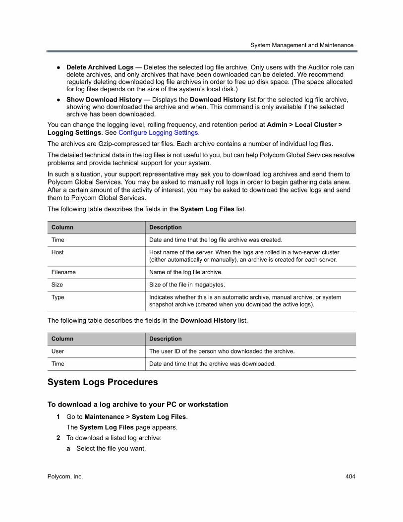
System Management and Maintenance
Polycom, Inc. 404
● Delete Archived Logs — Deletes the selected log file archive. Only users with the Auditor role can delete archives, and only archives that have been downloaded can be deleted. We recommend regularly deleting downloaded log file archives in order to free up disk space. (The space allocated for log files depends on the size of the system’s local disk.)
● Show Download History — Displays the Download History list for the selected log file archive, showing who downloaded the archive and when. This command is only available if the selected archive has been downloaded.
You can change the logging level, rolling frequency, and retention period at Admin > Local Cluster > Logging Settings. See Configure Logging Settings.
The archives are Gzip-compressed tar files. Each archive contains a number of individual log files.
The detailed technical data in the log files is not useful to you, but can help Polycom Global Services resolve problems and provide technical support for your system.
In such a situation, your support representative may ask you to download log archives and send them to Polycom Global Services. You may be asked to manually roll logs in order to begin gathering data anew. After a certain amount of the activity of interest, you may be asked to download the active logs and send them to Polycom Global Services.
The following table describes the fields in the System Log Files list.
The following table describes the fields in the Download History list.
System Logs Procedures
To download a log archive to your PC or workstation
1 Go to Maintenance > System Log Files.
The System Log Files page appears.
2 To download a listed log archive:
a Select the file you want.
Column Description
Time Date and time that the log file archive was created.
Host Host name of the server. When the logs are rolled in a two-server cluster (either automatically or manually), an archive is created for each server.
Filename Name of the log file archive.
Size Size of the file in megabytes.
Type Indicates whether this is an automatic archive, manual archive, or system snapshot archive (created when you download the active logs).
Column Description
User The user ID of the person who downloaded the archive.
Time Date and time that the archive was downloaded.
System Management and Maintenance
Polycom, Inc. 405
b In the Actions list, click Download Archived Logs.
c In the dialog, select a location and click Save.
3 To download an archive of the currently open log files (but not close them):
a In the Actions list, click Download Active Logs.
b In the dialog, specify a location and file name, and click Save.
To manually roll the system logs
1 Go to Maintenance > System Log Files.
The System Log Files page appears.
2 In the Actions list, click Roll Logs.
If you have a supercluster, you’re prompted to choose the cluster whose log files you want to roll.
3 If applicable, select a cluster. Wait a few seconds.
The system closes and archives the current log files and starts writing new ones. A dialog informs you that logs have been rolled, and the new log archive appears in the System Log Files list. For a two-server cluster, an archive is created for each server.
4 Click OK.
To delete a system log archive
1 Go to Maintenance > System Log Files.
The System Log Files page appears.
2 Select the log archive and verify that the Show Download History command appears, indicating that it has been downloaded at least once and can be deleted.
Click the command to see the Download History list.
3 In the Actions list, click Delete Archived Logs.
A confirmation dialog appears.
4 Click Yes.
See also:
Management and Maintenance Overview
Recommended Regular Maintenance
Alerts
Call Detail Records (CDRs)
Note: Deleting archives
Only users with the Auditor role can delete archives, and only archives that have been downloaded can be deleted.
System Management and Maintenance
Polycom, Inc. 406
Troubleshooting UtilitiesThe Polycom RealPresence DMA system’s Troubleshooting Utilities submenu includes several useful network and system status commands, which you can run and view the output of in the system’s familiar graphical interface. Each command is run on each server in the cluster, and the results are displayed in a separate panel for each server.
PingUse Ping to verify that the Polycom RealPresence DMA system’s servers can communicate with another device in the network.
To run ping on each server
1 Go to Maintenance > Troubleshooting Utilities > Ping.
2 Enter an IP address or host name and click Ping.
The system displays results of the command for each server.
TracerouteUse Traceroute to see the route that the servers use to reach the address you specify and the latency (round trip) for each hop.
To run traceroute on each server
1 Go to Maintenance > Troubleshooting Utilities > Traceroute.
2 Enter an IP address or host name and click Trace.
The system displays results of the command for each server.
TopUse Top to see an overview of each server’s current status, including CPU and memory usage, number of tasks, and list of running processes. The displays update every few seconds.
To run top on each server
» Go to Maintenance > Troubleshooting Utilities > Top.
The system displays results of the command for each server.
I/O StatsUse I/O Stats to see CPU resource allocation and read/write statistics for each server. For a detailed description of the output from this utility, refer to the utility documentation at http://sebastien.godard.pagesperso-orange.fr/man_iostat.html.
System Management and Maintenance
Polycom, Inc. 407
To run iostat on each server
» Go to Maintenance > Troubleshooting Utilities > I/O Stats.
The system displays results of the command for each server.
SARUse SAR to see a complete system activity report (from the preceding midnight to the current time) for each server.
To run sar on each server
» Go to Maintenance > Troubleshooting Utilities > SAR.
The system displays results of the command for each server.
NTP StatusUse NTP Status to see a list of clock sources known to each server (including the local clock) and their status. It runs the command ntpq -p on each server. For detailed information about the output of this command, see:
http://nlug.ml1.co.uk/2012/01/ntpq-p-output/831
To run ntpq -p on each server
» Go to Maintenance > Troubleshooting Utilities > NTP Status.
The system displays results of the command for each server.
See also:
Management and Maintenance Overview
Recommended Regular Maintenance
Check Configuration Synchronization Use Check Configuration Synchronization to find if there are any parts of the system configuration not correctly synchronized across all servers in the supercluster, and automatically repair the problems.
When you make configuration changes to the RealPresence DMA system, they are first stored locally on one of the servers in the supercluster, and synchronized soon after with the other servers. There are circumstances (usually due to network outages) where the local server can lose synchronization and the configuration becomes inconsistent between servers in the supercluster. This feature can detect and repair these inconsistencies.
When configuration synchronization checking is complete, the system stores the output from the analysis and repair in the configsynccheck-<date>.log file, which you can download as part of the active and archived system logs.
System Management and Maintenance
Polycom, Inc. 408
To check configuration synchronization
1 Go to Maintenance > Troubleshooting Utilities > Check Configuration Synchronization.
2 To automatically correct any problems, select Automatically correct synchronization issues.
3 Click OK.
A message appears explaining that configuration synchronization checking has started.
4 Click OK.
See also:
Management and Maintenance Overview
Recommended Regular Maintenance
Diagnostics for your Polycom ServerYou need to have a monitor and USB keyboard in order to run server diagnostics on your RealPresence DMA system, Appliance Edition hardware.
Perform these diagnostics only under the guidance of Polycom Global Services.
See also:
Management and Maintenance Overview
Recommended Regular Maintenance
Backing Up and RestoringLocal backups are performed and stored independently of remote backups. For more information on remote backups, see Configure Remote Backup Settings.
Every night, each Polycom RealPresence DMA system cluster creates a locally-stored configuration-only backup of the system, which includes:
● Local user account information (including local data for enterprise users, such as conference room attributes)
● System configuration data
● Supercluster and resource management system integration data (if applicable)
At any time, you can create either a configuration-only backup or a full backup, which adds all the transactional data, including logs, CDRs, network usage, and audit (history) data.
The backup file is for the cluster, but on a two-server cluster, a copy of the backup exists on each server. This ensures that the backup files are available even if one of the servers isn’t running.
The cluster keeps the most recent ten backups (deleting the oldest backup file when a new one is created).
Caution: May temporarily increase system load
This operation may take several minutes and may consume significant memory and CPU resources. Polycom recommends against invoking this utility during peak traffic periods or while other resource intensive tasks are underway (such as system backups, CDR downloads, or Microsoft Active Directory integration updates).
System Management and Maintenance
Polycom, Inc. 409
The Polycom RealPresence DMA system’s Backup and Restore page lets you:
● Manually create a full or configuration-only backup of that cluster.
● Download backup files from the cluster for safekeeping.
● Delete backup files to free up disk space.
● Upload backup files to the cluster.
● Restore from a configuration-only backup file, which lets you return the system state (IP network configuration, feature and system configuration, or both) to what was backed up, but leaves transactional data stores (including logs, CDRs, and audit data) empty.
● Restore from a full backup file, which lets you return both the system state and the transactional data stores (including logs, CDRs, and audit data) to what was backed up.
● If you have configured a remote backup storage server on the Admin > Local Cluster > Backup Settings page, you can transfer backup files to the remote server.
The option to omit IP network configuration (see Confirm Restore Dialog) makes it possible to “clone” an existing RealPresence DMA cluster’s feature and system configuration to a new cluster without introducing IP address conflicts.
In most cases, the software version of the backup file must match the system’s current software version in order to restore from it. But specific releases may include the ability to restore a backup file from specific earlier releases. For instance, because of a CentOS operating system change, no upgrade package is available for version 6.0.2. But after installing version 6.0.2 (overwriting the existing installation), you can restore your configuration and data from a version 5.2 backup.
The following table describes the fields in the Backup and Restore list.
Note: Backup removal
The system may delete additional backups to free up disk space if necessary.
Note: Best practices for backup data
We strongly suggest that you:
• Download backup files regularly for safekeeping, or transfer them to a remote storage server (see Configure Remote Backup Settings).
• Delete backup files after downloading in order to free up disk space.
• If you need to preserve transactional data and be able to restore it, configure remote backups to regularly perform a full backup and transfer it to remote storage (see Configure Remote Backup Settings).
• If you have a superclustered system, download backup files from each cluster (each cluster’s backup files include only the call, conference, and registration history for that cluster) or transfer the backup files to remote storage.
• Restore from a backup only when there is no activity on the system. Restoring terminates all conferences and reboots the system.
• For a two-server cluster, make system configuration changes, including restores, only when both servers are running and clustered.
If the system is shut down or in a bad state, the Polycom RealPresence DMA USB Configuration Utility (on the USB flash drive used to initially configure the network and system parameters) can restore the Polycom RealPresence DMA system from a backup file (full or configuration-only) that you load onto the USB flash drive.
System Management and Maintenance
Polycom, Inc. 410
See also:
Management and Maintenance Overview
Recommended Regular Maintenance
Confirm Restore Dialog
Backup and Restore Procedures
Confirm Restore DialogThe Confirm Restore dialog appears when you select a backup file and click Restore Selected in the Actions list.
If the backup file you selected is from a non-identical version of the software, you’re warned of the possible consequences and asked to confirm that you want to continue.
Select which data you want to restore and click OK. The options may include:
● IP network configuration
● Feature and system configuration
● History, network usage, and log data
Which data you can restore depends on:
● The type of backup file (full or config-only) you selected.
● For a restore from a non-identical software version, which restore operations the current version supports for the source version data.
See also:
Backing Up and Restoring
Column Description
Creation Date Timestamp of the backup file.
Name Name of the backup file.
Size Size of the backup file.
System Version Version number of the application that created the backup file.
SHA1 SHA1 checksum for the backup file. You can use this to confirm that a downloaded file is an exact copy of one on the server.
Caution: Restoring config-only backups
Restoring feature and system configuration, but not network configuration (or vice versa) will result in invalid primary or backup cluster assignments for some territories. After the restore operation is complete, go to Network > Site Topology > Territories and assign primary and backup clusters to the affected territories.
System Management and Maintenance
Polycom, Inc. 411
Backup and Restore Procedures
To download a backup file
1 Go to Maintenance > Backup and Restore.
The list contains the last ten backup files.
2 Select the backup file you want to download.
3 In the Actions list, click Download Selected.
4 Choose a path and filename for the backup file and click Save.
The File Download dialog indicates when the download is complete.
5 Click Close.
To create a new backup file
1 Go to Maintenance > Backup and Restore.
2 Verify that the oldest backup file listed is one you don’t want to keep or have already downloaded.
Only ten files are saved. Creating a new backup will delete the oldest file (unless there are fewer than ten).
3 In the Actions list, click Create New (Full) to create a full backup or Create New (Config Only) to create a configuration-only backup (no transaction data).
A confirmation dialog tells you the backup archive was created. For a full backup, this may take some time.
4 Click OK.
Caution: Restoring initiates a system restart
Restoring from a backup restarts the system and terminates all active conferences.
Note: Restoring backups with resource management integration
You can restore the system while it’s integrated with a Polycom RealPresence Resource Manager system, but the result depends on the state when the backup you’re restoring from was made.
If the system was integrated with a Polycom RealPresence Resource Manager system when the backup you’re restoring was made, that integration is restored. If the system wasn’t integrated when the backup was made, it will no longer be integrated after restoring.
Note: Backing up and restoring with superclusters
You can (and should) create and download backups from clusters that are part of a supercluster, but you can’t restore a cluster while it’s part of a supercluster. You must manually leave the supercluster first. If the cluster is responsible for any territories (as primary or backup), go to Network > Site Topology > Territories and reassign those territories.
If you restore a cluster using the USB Configuration Utility while it’s part of a supercluster, it’s automatically removed from the supercluster.
System Management and Maintenance
Polycom, Inc. 412
To upload a backup file
1 Go to Maintenance > Backup and Restore.
2 Verify that the oldest backup file listed is one you don’t want to keep or have already downloaded.
Only ten files are saved. Uploading a backup will delete the oldest file (unless there are fewer than ten).
3 In the Actions list, click Upload.
4 Choose a backup file to upload and click Open.
The File Upload dialog indicates when the upload is complete.
5 Click Close.
The system asks if you want to restore now from the backup file you just uploaded.
6 If you don’t want to restore (and restart the system) now, click Manually Later. When you’re ready to restore, use the procedure that follows this one.
7 To restore now, make sure you meet the criteria in the first two steps of the next procedure, and click Now.
The Confirm Restore dialog appears.
8 Read the warning, make sure that you want to continue, select which data you want to restore, and click OK.
After a short delay, a dialog informs you that the system is going to be restored and you’ll be logged out.
9 Click OK.
The system logs you out and the server reboots (typically, this takes about five minutes). After it comes back up, in a two-server cluster, the second server syncs to it, thus being restored to the same state. Depending on the configuration changes being applied, it may reboot so the changes can take effect.
When done, both servers’ LCDs display DMA Clustered (Polycom Rack Server 630 (R630) or 620 (R620)-based systems only).
10 Log back in as a local admin user and:
a In a two-server cluster, verify on the Dashboard that both servers are up and the private network connection is operating properly.
b Go to Maintenance > Software Upgrade and check the Operation History table.
c If the system was integrated with Active Directory, go to Admin > Integrations > Microsoft Active Directory and re-enable the integration.
To restore from a backup file on the cluster
1 If this is a two-server cluster, make sure that both servers are running and clustered. Make sure that there are no calls on the system, and that all MCUs are out of service. See Busy Out an MCU.
Caution: Restoring config-only backups
Restoring feature and system configuration, but not network configuration (or vice versa) will result in invalid primary or backup cluster assignments for some territories. After the restore operation is complete, go to Network > Site Topology > Territories and assign primary and backup clusters to the affected territories.
System Management and Maintenance
Polycom, Inc. 413
2 If this cluster is part of a supercluster, remove it from the supercluster. See Supercluster Procedures.
3 Go to Maintenance > Backup and Restore.
4 Select the backup file from which you want to restore.
5 In the Actions list, click Restore Selected.
The Confirm Restore dialog appears.
6 Read the warning, make sure that you want to continue, select which data you want to restore, and click OK.
After a short delay, a dialog informs you that the system is going to be restored and you’ll be logged out.
7 Click OK.
The system logs you out and the server reboots (typically, this takes about five minutes). After it comes back up, in a two-server cluster, the second server syncs to it, restoring it to the same state. Depending on the changes being applied, it may reboot so the changes can take effect.
When done, both servers’ LCDs display DMA Clustered. (Polycom Rack Server 630 (R630) or 620 (R620)-based systems only).
8 Log back in as a local admin user and:
a In a two-server cluster, verify on the Dashboard that both servers are up and the private network connection is operating properly.
b Go to Maintenance > Software Upgrade and check the Operation History table.
c If the system was integrated with AD, go to Admin > Integrations > Microsoft Active Directory and re-enable the integration.
To restore from a backup file on the Polycom RealPresence DMA system’s USB flash drive
1 If the system is running and accessible, log in as an Administrator, make sure that there are no calls on the system and that all MCUs are out of service. See Busy Out an MCU.
2 Shut down the system. See Shutting Down and Restarting.
3 Connect the USB memory stick containing the RealPresence DMA USB Configuration Utility (included with your Polycom RealPresence DMA system) to a Windows PC.
Caution: Restoring config-only backups
Restoring feature and system configuration, but not network configuration (or vice versa) will result in invalid primary or backup cluster assignments for some territories. After the restore operation is complete, go to Network > Site Topology > Territories and assign primary and backup clusters to the affected territories.
Note: Restoring with the USB configuration utility
When you use the USB Configuration Utility to restore a backup, you can’t select which data to restore. If you copy a config-only backup file to the USB flash drive, both the feature and system configuration data and the IP network configuration data will be restored. If you copy a full backup file to the USB flash drive, the transactional (historical) data will also be restored.
Only backups from identical versions of the software can be restored using the USB Configuration Utility.
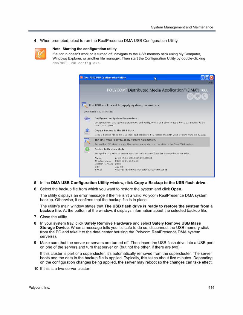
System Management and Maintenance
Polycom, Inc. 414
4 When prompted, elect to run the RealPresence DMA USB Configuration Utility.
5 In the DMA USB Configuration Utility window, click Copy a Backup to the USB flash drive.
6 Select the backup file from which you want to restore the system and click Open.
The utility displays an error message if the file isn’t a valid Polycom RealPresence DMA system backup. Otherwise, it confirms that the backup file is in place.
The utility’s main window states that The USB flash drive is ready to restore the system from a backup file. At the bottom of the window, it displays information about the selected backup file.
7 Close the utility.
8 In your system tray, click Safely Remove Hardware and select Safely Remove USB Mass Storage Device. When a message tells you it’s safe to do so, disconnect the USB memory stick from the PC and take it to the data center housing the Polycom RealPresence DMA system server(s).
9 Make sure that the server or servers are turned off. Then insert the USB flash drive into a USB port on one of the servers and turn that server on (but not the other, if there are two).
If this cluster is part of a supercluster, it’s automatically removed from the supercluster. The server boots and the data in the backup file is applied. Typically, this takes about five minutes. Depending on the configuration changes being applied, the server may reboot so the changes can take effect.
10 If this is a two-server cluster:
Note: Starting the configuration utility
If autorun doesn’t work or is turned off, navigate to the USB memory stick using My Computer, Windows Explorer, or another file manager. Then start the Configuration Utility by double-clicking dma7000-usb-config.exe.
System Management and Maintenance
Polycom, Inc. 415
a For a Polycom Rack Server 630 (R630) or 620 (R620)-based cluster: After the first server has rebooted (if necessary) and its front-panel LCD displays DMA Ready, turn on the second server.
The second server boots, finds the first server, and syncs to it, thus being restored to the same state. Depending on the configuration changes being applied, it may reboot so the changes can take effect.
When done, both servers’ LCDs display DMA Clustered.
b For a Polycom Rack Server 220-based cluster: After the first server has rebooted (if necessary) and has been running for at least 10 minutes, turn on the second server.
The second server boots, finds the first server, and syncs to it, thus being restored to the same state. Depending on the configuration changes being applied, it may reboot so the changes can take effect.
11 Log back in as a local admin user and:
a In a two-server cluster, verify on the Dashboard that both servers are up and the private network connection is operating properly.
b Go to Maintenance > Software Upgrade and check the Operation History table.
c If the system was integrated with Active Directory, go to Admin > Integrations > Microsoft Active Directory and re-enable the integration.
See also:
Backing Up and Restoring
Confirm Restore Dialog
Upgrading the SoftwareThe Polycom RealPresence DMA system’s Software Upgrade page lets you upload a software upgrade package and install the upgrade on your system (both servers, if present). It also lets you roll back to the previous version, if necessary.
This process can be used for patches, minor upgrades, and major upgrades. In all three cases, the current system configuration (including users, MCUs, Conference Manager settings, Call Server settings, and local cluster settings) is preserved.
Patches don’t require new license keys, but major and minor version upgrades do. Any of the three may require a system restart. If so, that information is displayed on the page after you upload the upgrade package.
The following table describes the parts of the Software Upgrade page.
Note: Virtual host names and IP addresses unnecessary for single servers
This version of the Polycom RealPresence DMA system eliminates the need for virtual host name(s) and IP addresses in a single-server system. When a version 5.0 or earlier single-server RealPresence DMA system is upgraded to version 5.1 or later, the previous version's virtual host name(s) and IP addresses become the upgraded version's physical host name(s) and IP addresses, so accessing the system doesn't change.
(Exception: If only IPv6 is enabled, the system must have two addresses, so a single-server system must still have a virtual host name and IP address.)
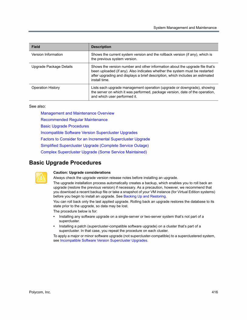
System Management and Maintenance
Polycom, Inc. 416
See also:
Management and Maintenance Overview
Recommended Regular Maintenance
Basic Upgrade Procedures
Incompatible Software Version Supercluster Upgrades
Factors to Consider for an Incremental Supercluster Upgrade
Simplified Supercluster Upgrade (Complete Service Outage)
Complex Supercluster Upgrade (Some Service Maintained)
Basic Upgrade Procedures
Field Description
Version Information Shows the current system version and the rollback version (if any), which is the previous system version.
Upgrade Package Details Shows the version number and other information about the upgrade file that’s been uploaded (if any). Also indicates whether the system must be restarted after upgrading and displays a brief description, which includes an estimated install time.
Operation History Lists each upgrade management operation (upgrade or downgrade), showing the server on which it was performed, package version, date of the operation, and which user performed it.
Caution: Upgrade considerations
Always check the upgrade version release notes before installing an upgrade.
The upgrade installation process automatically creates a backup, which enables you to roll back an upgrade (restore the previous version) if necessary. As a precaution, however, we recommend that you download a recent backup file or take a snapshot of your VM instance (for Virtual Edition systems) before you begin to install an upgrade. See Backing Up and Restoring.
You can roll back only the last applied upgrade. Rolling back an upgrade restores the database to its state prior to the upgrade, so data may be lost.
The procedure below is for:
• Installing any software upgrade on a single-server or two-server system that’s not part of a supercluster.
• Installing a patch (supercluster-compatible software upgrade) on a cluster that’s part of a supercluster. In that case, you repeat the procedure on each cluster.
To apply a major or minor software upgrade (not supercluster-compatible) to a superclustered system, see Incompatible Software Version Supercluster Upgrades.
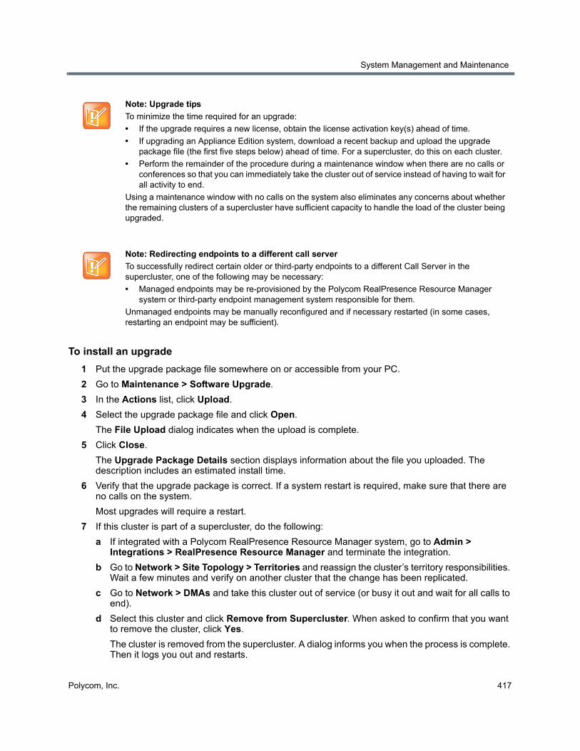
System Management and Maintenance
Polycom, Inc. 417
To install an upgrade
1 Put the upgrade package file somewhere on or accessible from your PC.
2 Go to Maintenance > Software Upgrade.
3 In the Actions list, click Upload.
4 Select the upgrade package file and click Open.
The File Upload dialog indicates when the upload is complete.
5 Click Close.
The Upgrade Package Details section displays information about the file you uploaded. The description includes an estimated install time.
6 Verify that the upgrade package is correct. If a system restart is required, make sure that there are no calls on the system.
Most upgrades will require a restart.
7 If this cluster is part of a supercluster, do the following:
a If integrated with a Polycom RealPresence Resource Manager system, go to Admin > Integrations > RealPresence Resource Manager and terminate the integration.
b Go to Network > Site Topology > Territories and reassign the cluster’s territory responsibilities. Wait a few minutes and verify on another cluster that the change has been replicated.
c Go to Network > DMAs and take this cluster out of service (or busy it out and wait for all calls to end).
d Select this cluster and click Remove from Supercluster. When asked to confirm that you want to remove the cluster, click Yes.
The cluster is removed from the supercluster. A dialog informs you when the process is complete. Then it logs you out and restarts.
Note: Upgrade tips
To minimize the time required for an upgrade:
• If the upgrade requires a new license, obtain the license activation key(s) ahead of time.
• If upgrading an Appliance Edition system, download a recent backup and upload the upgrade package file (the first five steps below) ahead of time. For a supercluster, do this on each cluster.
• Perform the remainder of the procedure during a maintenance window when there are no calls or conferences so that you can immediately take the cluster out of service instead of having to wait for all activity to end.
Using a maintenance window with no calls on the system also eliminates any concerns about whether the remaining clusters of a supercluster have sufficient capacity to handle the load of the cluster being upgraded.
Note: Redirecting endpoints to a different call server
To successfully redirect certain older or third-party endpoints to a different Call Server in the supercluster, one of the following may be necessary:
• Managed endpoints may be re-provisioned by the Polycom RealPresence Resource Manager system or third-party endpoint management system responsible for them.
Unmanaged endpoints may be manually reconfigured and if necessary restarted (in some cases, restarting an endpoint may be sufficient).
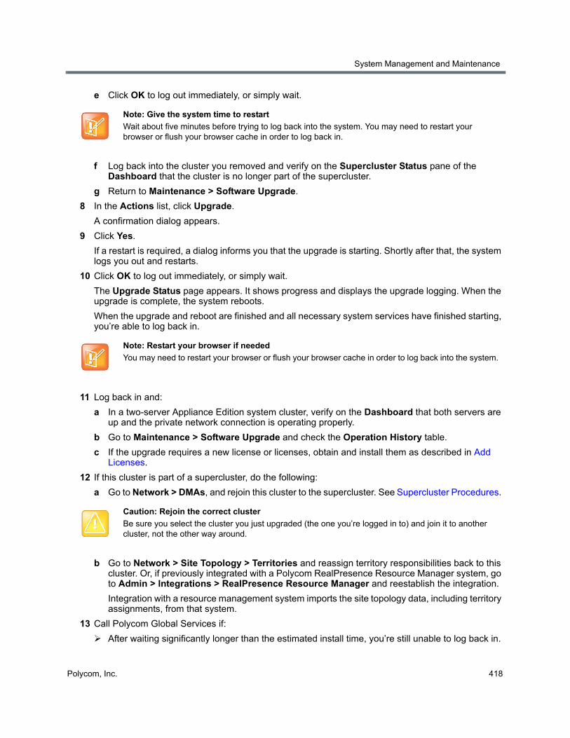
System Management and Maintenance
Polycom, Inc. 418
e Click OK to log out immediately, or simply wait.
f Log back into the cluster you removed and verify on the Supercluster Status pane of the Dashboard that the cluster is no longer part of the supercluster.
g Return to Maintenance > Software Upgrade.
8 In the Actions list, click Upgrade.
A confirmation dialog appears.
9 Click Yes.
If a restart is required, a dialog informs you that the upgrade is starting. Shortly after that, the system logs you out and restarts.
10 Click OK to log out immediately, or simply wait.
The Upgrade Status page appears. It shows progress and displays the upgrade logging. When the upgrade is complete, the system reboots.
When the upgrade and reboot are finished and all necessary system services have finished starting, you’re able to log back in.
11 Log back in and:
a In a two-server Appliance Edition system cluster, verify on the Dashboard that both servers are up and the private network connection is operating properly.
b Go to Maintenance > Software Upgrade and check the Operation History table.
c If the upgrade requires a new license or licenses, obtain and install them as described in Add Licenses.
12 If this cluster is part of a supercluster, do the following:
a Go to Network > DMAs, and rejoin this cluster to the supercluster. See Supercluster Procedures.
b Go to Network > Site Topology > Territories and reassign territory responsibilities back to this cluster. Or, if previously integrated with a Polycom RealPresence Resource Manager system, go to Admin > Integrations > RealPresence Resource Manager and reestablish the integration.
Integration with a resource management system imports the site topology data, including territory assignments, from that system.
13 Call Polycom Global Services if:
After waiting significantly longer than the estimated install time, you’re still unable to log back in.
Note: Give the system time to restart
Wait about five minutes before trying to log back into the system. You may need to restart your browser or flush your browser cache in order to log back in.
Note: Restart your browser if needed
You may need to restart your browser or flush your browser cache in order to log back into the system.
Caution: Rejoin the correct cluster
Be sure you select the cluster you just upgraded (the one you’re logged in to) and join it to another cluster, not the other way around.

System Management and Maintenance
Polycom, Inc. 419
You can log in, but the Dashboard shows only one server for a two-server cluster.
The package version numbers on the two servers are not the same.
14 For a supercluster, repeat the above procedure for each additional cluster.
To roll back an upgrade, restoring the previous version
1 Go to Maintenance > Software Upgrade.
2 Verify that you want to downgrade the system to the rollback version shown and that you’re prepared for a system restart, if required.
Most rollbacks will require a restart.
3 If this cluster is part of a supercluster and you’re rolling back after rejoining the supercluster, do the following:
a If integrated with a Polycom RealPresence Resource Manager system, go to Admin > Integrations > RealPresence Resource Manager and terminate the integration.
b Go to Network > Site Topology > Territories and reassign the cluster’s territory responsibilities. Wait a few minutes and verify on another cluster that the change has been replicated.
c Go to Network > DMAs and take it out of service (or busy it out and wait for all calls to end).
d Select this cluster and click Remove from Supercluster. When asked to confirm that you want to remove the cluster, click Yes.
The cluster is removed from the supercluster. A dialog informs you when the process is complete. Then it logs you out and restarts.
e Click OK to log out immediately, or simply wait.
f Log back into the cluster you removed and verify on the Supercluster Status pane of the Dashboard that the cluster is no longer part of the supercluster.
g Return to Maintenance > Software Upgrade.
4 In the Actions list, click Roll Back.
A confirmation dialog appears.
5 Click Yes.
If a restart is required, a dialog informs you that the downgrade is starting. Shortly after that, the system logs you out and restarts.
6 Click OK to log out immediately, or simply wait.
When the downgrade process is finished and all necessary system services have finished starting, you’re able to log back in.
7 Log back in and:
Note: Give the system time to restart
Wait about five minutes before trying to log back into the system. You may need to restart your browser or flush your browser cache in order to do log back in.
Note: Restart your browser if necessary
You may need to restart your browser or flush your browser cache in order to log back into the system.
System Management and Maintenance
Polycom, Inc. 420
a In a two-server cluster, verify on the Dashboard that both servers are up and the private network connection is operating properly.
b Go to Maintenance > Software Upgrade and check the Operation History table.
8 If this cluster is part of a supercluster, do the following:
a Go to Network > DMAs, and rejoin this cluster to the supercluster. See Supercluster Procedures.
b Go to Network > Site Topology > Territories and reassign territory responsibilities back to this cluster. Or, if previously integrated with a Polycom RealPresence Resource Manager system, go to Admin > Integrations > RealPresence Resource Manager and reestablish the integration.
Integration with a resource management system imports the site topology data, including territory assignments, from that system.
9 Call Polycom Global Services if:
After waiting significantly longer than the estimated install time, you’re still unable to log back in.
You can log in, but the Dashboard shows only one server for a two-server cluster.
The package version numbers on the two servers are not the same.
See also:
Management and Maintenance Overview
Upgrading the Software
Incompatible Software Version Supercluster UpgradesAll the clusters in a supercluster must be running compatible software versions. Patch releases will generally be compatible, and can be installed using the procedure in Basic Upgrade Procedures.
But major and minor version upgrades will not be compatible. An incompatible version software upgrade on all clusters in a supercluster requires careful planning because it’s not possible to upgrade a cluster to an incompatible software version while it’s a member of the supercluster. Each cluster must be upgraded individually.
You have two options for upgrading a supercluster:
● Perform the cluster upgrades in a system-wide maintenance window during which all the clusters can be shut down and the service is completely unavailable. This is by far the simplest and fastest method, taking as little as an hour or two.
● Perform the cluster upgrades incrementally so that some system capacity (although greatly reduced) remains available during the process. This method is far more complex, error-prone, and lengthy. It can easily take five or more times as long.
During the course of an incremental upgrade, some clusters will be on the new software version while others are still on the older version, effectively creating two separate superclusters until all the clusters are upgraded. This requires significant configuration changes in order for some level of service to remain available, and those configuration changes must be repeated again and again as each cluster is removed from the original supercluster, upgraded, and added to the new supercluster.
Before deciding to undertake an incremental upgrade, carefully read and consider the information in Factors to Consider for an Incremental Supercluster Upgrade.
Caution: Rejoin the correct cluster
Be sure you select the cluster you just downgraded (the one you’re logged in to) and join it to another cluster, not the other way around.
System Management and Maintenance
Polycom, Inc. 421
See also:
Upgrading the Software
Basic Upgrade Procedures
Simplified Supercluster Upgrade (Complete Service Outage)
Complex Supercluster Upgrade (Some Service Maintained)
Factors to Consider for an Incremental Supercluster UpgradeBefore deciding to attempt an incremental supercluster software upgrade, be aware of the following:
● An incremental upgrade can easily take five times as long as the simplified method.
● As clusters are removed from the existing supercluster and upgraded, its capacity is reduced. As the new supercluster is being built, it won’t be at full capacity until all clusters are upgraded. Both the existing supercluster and the new one will have limited capacity for a significant period of time, with the following possible consequences:
Some endpoints may be unable to register.
The MCUs remaining in the supercluster may not have the capacity to handle all the conferences.
Some endpoints may not successfully redirect their registrations and may not be able to make/receive calls.
● As the old supercluster is deconstructed, the territory associations have to be changed each time a cluster leaves. As the new supercluster is built, the territory associations have to be changed each time a cluster joins.
● As the clusters for some endpoints are removed from the existing supercluster and join the new one, the video network becomes partitioned with separate islands of endpoints.
● Some endpoints don’t respond well to a gatekeeper change (such as a signaled alternate gatekeeper). To successfully redirect these endpoints to a Call Server in the new supercluster, one of the following may be necessary:
Managed endpoints may be re-provisioned by the Polycom RealPresence Resource Manager system, or third-party endpoint management system responsible for them.
Unmanaged endpoints may be manually reconfigured and if necessary restarted (in some cases, restarting an endpoint may be sufficient).
● Any configuration changes to the old supercluster (once the first cluster has left) may be lost when the new supercluster is created.
Caution: Use care when upgrading a supercluster
We strongly recommend upgrading a supercluster only during a system-wide maintenance window when there are no calls or conferences on the system and all clusters can be taken out of service. This makes the process significantly faster and easier.
If you must upgrade incrementally, be aware of the limited capacity available at any given point in the process. It’s advisable to ensure that there is little or no conferencing activity in any given territory until after the new supercluster has been created and territory responsibilities for that territory have been reassigned to a cluster in the new supercluster.
To minimize the time required for an upgrade:
• If the upgrade requires a new license, obtain the license keys ahead of time.
Download a recent backup and upload the upgrade package file to all clusters in the supercluster ahead of time.

System Management and Maintenance
Polycom, Inc. 422
● History records for calls and conferences that cross from the old supercluster to the new one (and vice versa) will not be merged into a single call/conference after the upgrade.
● If embedded DNS is enabled, the enterprise DNS can only point to one supercluster. The other supercluster will not have territory fail-over capability.
● If Conference Manager is enabled, during the time that the supercluster is split into two, each supercluster could host separate conferences on the same VMR.
● The site topology bandwidth specifications will be duplicated in both the old supercluster and the new supercluster. Without significant changes to the site topology’s bandwidth configuration, this can lead to bandwidth overloading during the upgrade.
See also:
Upgrading the Software
Basic Upgrade Procedures
Simplified Supercluster Upgrade (Complete Service Outage)If it’s possible to schedule the upgrade for a maintenance window during which there is no service, we strongly recommend doing so, as described below. This greatly shortens and simplifies the process.
To upgrade a supercluster by taking all clusters out of service
1 Put the upgrade package file somewhere on or accessible from your PC.
2 On each cluster in the supercluster, do the following:
a Go to Maintenance > Software Upgrade.
b In the Actions list, click Upload.
c Select the upgrade package file and click Open.
The File Upload dialog indicates when the upload is complete.
Caution: Upgrade considerations
Always check the upgrade version release notes before installing an upgrade.
The upgrade installation process automatically creates a backup, which enables you to roll back an upgrade (restore the previous version) if necessary. As a precaution, however, we recommend that you download a recent backup file before you begin to install an upgrade. See Backing Up and Restoring.
You can roll back only the last applied upgrade. Rolling back an upgrade restores the database to its state prior to the upgrade, so data may be lost.
The procedure below is for applying a major or minor software upgrade (not supercluster-compatible) to a superclustered system.
To minimize the time required for an upgrade:
• Obtain the license activation key(s) ahead of time.
• On each cluster, download a recent backup and upload the upgrade package file (the first two steps below) ahead of time.
Perform the remainder of the procedure during a maintenance window when there are no calls or conferences so that you can immediately take all the clusters out of service instead of having to wait for all activity to end.
System Management and Maintenance
Polycom, Inc. 423
d Click Close.
The Upgrade Package Details section displays information about the file you uploaded. The description includes an estimated install time.
e Verify that the upgrade package is correct.
3 On any cluster in the supercluster, do the following:
a Go to Network > Site Topology > Territories and record each territory’s primary and backup cluster, whether it hosts conference rooms, and associated sites.
You may need this information later to restore the configuration.
b If there are no active calls and conferences, skip to d. Otherwise, go to Network > DMAs and busy out each cluster in the supercluster.
This permits existing calls and conferences to continue, but prevents new conferences and point-to-point calls from starting.
c On the Dashboard, monitor the Call Server Active Calls and Conference Manager MCUs panes.
d When all calls and conferences have ended, go to Network > DMAs and stop using each cluster in the supercluster.
This completely shuts down the supercluster.
e Remove each cluster except the one you’re logged in to from the supercluster.
As each cluster is removed, it restarts.
4 On the cluster you’re logged in to (let’s call it cluster A), do the following:
a Go to Maintenance > Software Upgrade.
b In the Actions list, click Upgrade.
A confirmation dialog appears.
c Click Yes.
If a restart is required, a dialog informs you that the upgrade is starting. Shortly after that, the system logs you out and restarts.
d Click OK to log out immediately, or simply wait.
The Upgrade Status page appears. It shows progress and displays the upgrade logging. When the upgrade is complete, the system reboots.
When the upgrade and reboot are finished and all necessary system services have finished starting, you’re able to log back in.
Note: Save time with cluster upgrades
If you have assistants to help you, they can perform steps 5 and 6, upgrading all the other clusters simultaneously, while the upgrade package is being installed on cluster A. If not, you can start upgrading cluster B at this point, and as soon as it restarts, start upgrading the next cluster, and so on. You don’t need to wait for each cluster upgrade to be finished before starting the next one.
Note: Restart your browser
You may need to restart your browser or flush your browser cache in order to log back into the system.
System Management and Maintenance
Polycom, Inc. 424
e Log back in and, in a two-server cluster, verify on the Dashboard that both servers are up and the private network connection is operating properly.
f Go to Maintenance > Software Upgrade and check the Operation History table.
g If the upgrade requires a new license activation key code or codes, obtain and install them as described in Add Licenses.
5 Log into one of the other clusters (let’s call it cluster B) and do the following:
a Go to Maintenance > Software Upgrade.
b In the Actions list, click Upgrade.
A confirmation dialog appears.
c Click Yes.
If a restart is required, a dialog informs you that the upgrade is starting. Shortly after that, the system logs you out and restarts.
d Click OK to log out immediately, or simply wait.
When the upgrade process is finished and all necessary system services have finished starting, you’re able to log back in.
e Log back in and, in a two-server cluster, verify on the Dashboard that both servers are up and the private network connection is operating properly.
f Go to Maintenance > Software Upgrade and check the Operation History table.
g If the upgrade requires a new license activation key code or codes, obtain and install them as described in Add Licenses.
h Go to Network > DMAs and join this cluster to cluster A to create a supercluster.
You now have a new supercluster consisting of two upgraded clusters.
6 For each additional cluster, repeat step 5 of this procedure to upgrade it and add it to the new supercluster.
7 On any cluster of the new supercluster, do the following:
a Go to Network > Site Topology > Territories and restore the territory assignments that you recorded at step 3a of this procedure. Or, if previously integrated with a Polycom RealPresence Resource Manager system, go to Admin > Integrations > RealPresence Resource Manager and reestablish the integration.
Integration with a resource management system imports the site topology data, including territory assignments, from that system.
b Go to Network > DMAs and return each cluster to service.
c Verify, and restore or update if necessary, other supercluster configuration settings.
You should now have a fully functional upgraded supercluster.
8 Call Polycom Global Services if, for any cluster:
After waiting significantly longer than the estimated install time, you’re still unable to log back in.
You can log in, but the Dashboard shows only one server for a two-server cluster.
Note: Restart your browser
You may need to restart your browser or flush your browser cache in order to log back into the system.
System Management and Maintenance
Polycom, Inc. 425
The package version numbers on the two servers are not the same.
See also:
Upgrading the Software
Basic Upgrade Procedures
Factors to Consider for an Incremental Supercluster Upgrade
Complex Supercluster Upgrade (Some Service Maintained)Please contact Polycom Global Services for instructions and assistance.
RealPresence DMA System, Virtual Edition System UpgradeUpgrading a RealPresence DMA system, Virtual Edition is very similar to upgrading an Appliance Edition system, with the exceptions of system backups and licensing.
To upgrade a RealPresence DMA system, Virtual Edition
1 Log in to the system’s web interface using a web browser.
2 Power down the system instance using the Shut Down button on the Maintenance > Shutdown and Restart page.
3 Using your VM host software, save a snapshot of the RealPresence DMA system, Virtual Edition instance. See your VM host documentation for instructions on taking snapshots.
4 Power on the system instance using the VM host software.
5 Follow the normal upgrade procedure outlined in Basic Upgrade Procedures.
6 License the system, if necessary. See Add Licenses to the RealPresence DMA system, Virtual Edition for more information.
When upgrading from a version prior to 6.1 to a version 6.1 or later system, you must contact your Polycom sales representative to obtain a license for the Virtual Edition system. Virtual Edition systems have no basic call capability if they are not licensed.
See also:
Upgrading the Software
Basic Upgrade Procedures
Factors to Consider for an Incremental Supercluster Upgrade
Simplified Supercluster Upgrade (Complete Service Outage)
Adding a Second ServerA single-server Polycom RealPresence DMA system can be upgraded to a fault-tolerant two-server cluster at any time. For an overview of how a two-server cluster works and its advantages, see Two-server Cluster Configuration.
To form a two-server cluster, both servers must be running the same version of the Polycom RealPresence DMA system software. Depending on the software level of your existing server, you can accomplish this in one of two ways:
System Management and Maintenance
Polycom, Inc. 426
● If your existing server is running an unpatched release version of the system software for which you have the installation DVD, follow the procedure in Expanding an Unpatched Polycom Rack Server 630 (R630) or 620 (R620)-Based System or Expanding an Unpatched Polycom Rack Server 220 (R220)-Based System, depending on which type of servers you have.
● If your existing server is running a patched version of the system software different from that on the installation DVD, follow the procedure in Expanding a Patched Polycom Rack Server 630 (R630) or 620 (R620)-Based System or Expanding a Patched Polycom Rack Server 220 (R220)-Based System, depending on which type of servers you have.
All of the procedures assume that you’ve ordered and received the server expansion package, which includes the second server, its accessories, and a new License Certificate, if applicable.
See also:
Management and Maintenance Overview
Expanding an Unpatched Polycom Rack Server 630 (R630) or 620 (R620)-Based SystemFollow the instructions in this section to expand an unpatched system based on the Polycom Rack Server 630 (R630) or 620 (R620).
To expand an unpatched single-server Polycom Rack Server 630 or 620-based system into a two-server cluster
1 Unpack, inspect, and physically install the second server as described in its Getting Started Guide. Mount it in the rack adjacent to the first Polycom RealPresence DMA system server (or close enough to connect them with an Ethernet cable).
2 Log into your Polycom RealPresence DMA system, go to Admin >Local Cluster > Network Settings, change System server configuration to 2 server configuration, and add the Server 2 host name(s) and IP address(es) for the second server. See Network Settings.
The first server (Server 1) reboots.
3 Connect the second server to the network:
a Connect the GB 1 Ethernet port of the new server to the enterprise network.
b Use an Ethernet cable to connect the GB 2 ports of the two servers.
4 Confirm that the first server is running and displays DMA Ready. Then turn on the second server, insert the installation DVD, and reboot it.
The server boots from the DVD, and the installation commences. About 15-20 minutes later, the DVD ejects and the server reboots. It detects the presence of Server 1, gets its configuration settings from it, and joins the cluster. When done, both servers’ LCDs display DMA Clustered.
Note: Downloadable installation DVD image
If the original DVD installation disc is destroyed or lost, you can download the DVD image from the Polycom support portal and write it to a blank, writable DVD. A valid software license key is required to access the DVD image file.
Caution: Allow first server to start fully
The first server must be running properly before you turn on the second server.
System Management and Maintenance
Polycom, Inc. 427
5 Log into the system, go to Admin > Local Cluster > Licenses, and follow the procedure for obtaining and entering a license activation key. See Add Licenses.
6 On the Dashboard, check the License Status, Supercluster Status, and Cluster Info panes to verify that you now have a properly configured two-server cluster.
See also:
Management and Maintenance Overview
Adding a Second Server
Expanding a Patched Polycom Rack Server 630 (R630) or 620 (R620)-Based System
Expanding a Patched Polycom Rack Server 630 (R630) or 620 (R620)-Based SystemFollow the instructions in this section to expand a patched system based on the Polycom Rack Server 630 (R630) or 620 (R620).
To expand a patched single-server Polycom Rack Server 630 or 620-based system into a two-server cluster
1 Unpack, inspect, and physically install the second server as described in its Getting Started Guide. Mount it in the rack adjacent to the first Polycom RealPresence DMA system server (or close enough to connect them with an Ethernet cable).
2 Connect the GB 1 Ethernet port of the new server to the enterprise network. Don’t connect the crossover cable between the two servers at this time.
3 Log into your existing Polycom RealPresence DMA system and determine the software version (including patch level) installed on the first (existing) server. Write it down for later reference.
4 Go to Admin >Local Cluster > Network Settings, change System server configuration to 2 server configuration, and add the Server 2 host name and IP address for the second server. See Network Settings.
The first server (Server 1) reboots.
5 Shut down the first server (Server 1).
6 Using the USB Configuration Utility and the procedure in the Getting Started Guide, complete the installation and initial configuration of the new server as a stand-alone single-server system. If necessary, use your installation DVD to install the same release version of the software that’s on your first server.
7 Log into the new server, go to Maintenance > Software Upgrade, and install the patch(es) needed to make it match the software version on the first server. See Upgrading the Software.
Note: Downloadable installation DVD image
If the original DVD system recovery disc is destroyed or lost, you can download the system recovery DVD image from the Polycom support portal and write it to a blank, writable DVD. A valid software license key is required to download the DVD image file.
Caution: Assign the Server its Own IP Address(es)
Assign the new server its own real and virtual IP addresses. Don’t assign it the virtual IP address of the existing system.
System Management and Maintenance
Polycom, Inc. 428
8 Shut down the new server. See Shutting Down and Restarting.
9 Use an Ethernet cable to connect the GB 2 ports of the two servers.
10 Turn on the first server (Server 1).
11 When the first server displays DMA Ready, turn on the second server.
The second server boots, detects the presence of Server 1, gets its configuration settings from it, and joins the cluster. When done, both servers’ LCDs display DMA Clustered.
12 Log into the system and follow the procedure for licensing the system. See Add Licenses.
13 On the Dashboard, check the License Status, Supercluster Status, and Cluster Info panes to verify that you now have a properly configured two-server cluster.
See also:
Management and Maintenance Overview
Adding a Second Server
Expanding an Unpatched Polycom Rack Server 630 (R630) or 620 (R620)-Based System
Expanding an Unpatched Polycom Rack Server 220 (R220)-Based SystemFollow the instructions in this section to expand an unpatched system based on the Polycom Rack Server 220.
To expand an unpatched single-server Polycom Rack Server 220-based system into a two-server cluster
1 Unpack, inspect, and physically install the second server as described in its Getting Started Guide. Mount it in the rack adjacent to the first Polycom RealPresence DMA system server (or close enough to connect them with an Ethernet cable).
2 Log into your Polycom RealPresence DMA system, go to Admin > Local Cluster > Network Settings, change System server configuration to 2 server configuration, and add the Server 2 host name(s) and IP address(es) for the second server. See Network Settings.
The first server (Server 1) reboots.
3 Connect the second server to the network:
a Connect the Port 0 Ethernet port of the new server to the enterprise network.
b Use an Ethernet cable to connect the Port 1 ports of the two servers.
Caution: Allow first server to start fully
The first server must be running properly before you turn on the second server.
Note: Downloadable installation DVD image
If the original DVD installation disc is destroyed or lost, you can download the DVD image from the Polycom support portal and write it to a blank, writable DVD. A valid software license key is required to access the DVD image file.
System Management and Maintenance
Polycom, Inc. 429
4 Wait 10 minutes for the first server to finish starting up and become ready. Then turn on the second server, insert the installation DVD, and reboot it.
The server boots from the DVD, and the installation commences. About 15-20 minutes later, the DVD ejects and the server reboots. It detects the presence of Server 1, gets its configuration settings from it, and joins the cluster.
5 Log in to the system and follow the procedure for licensing the system. See Add Licenses.
6 On the Dashboard, check the License Status, Supercluster Status, and Cluster Info panes to verify that you now have a properly configured two-server cluster.
See also:
Management and Maintenance Overview
Adding a Second Server
Expanding a Patched Polycom Rack Server 630 (R630) or 620 (R620)-Based System
Expanding a Patched Polycom Rack Server 220 (R220)-Based SystemFollow the instructions in this section to expand a patched system based on the Polycom Rack Server 220.
To expand a patched single-server Polycom Rack Server 220-based system into a two-server cluster
1 Unpack, inspect, and physically install the second server as described in its Getting Started Guide. Mount it in the rack adjacent to the first Polycom RealPresence DMA system server (or close enough to connect them with an Ethernet cable).
2 Connect the Port 0 Ethernet port of the new server to the enterprise network. Don’t connect the crossover cable between the two servers at this time.
3 Log into your existing Polycom RealPresence DMA system and determine the software version (including patch level) installed on the first (existing) server. Write it down for later reference.
4 Go to Admin > Local Cluster > Network Settings, change System server configuration to 2 server configuration, and add the Server 2 host name and IP address for the second server. See Network Settings.
The first server (Server 1) reboots.
5 Shut down the first server (Server 1).
6 Using the USB Configuration Utility and the procedure in the Getting Started Guide, complete the installation and initial configuration of the new server as a stand-alone single-server system. If necessary, use your installation DVD to install the same release version of the software that’s on your first server.
Caution: Allow first server to start fully
The first server must be running properly before you turn on the second server.
Note: Downloadable installation DVD image
If the original DVD system recovery disc is destroyed or lost, you can download the system recovery DVD image from the Polycom support portal and write it to a blank, writable DVD. A valid software license key is required to download the DVD image file.

System Management and Maintenance
Polycom, Inc. 430
7 Log into the new server, go to Maintenance > Software Upgrade, and install the patch(es) needed to make it match the software version on the first server. See Upgrading the Software.
8 Shut down the new server. See Shutting Down and Restarting.
9 Use an Ethernet cable to connect the Port 1 ports of the two servers.
10 Turn on the first server (Server 1).
11 Wait 10 minutes for the first server to finish starting up and become ready. Then, turn on the second server.
The second server boots, detects the presence of Server 1, gets its configuration settings from it, and joins the cluster.
12 Log into the system and follow the procedure for licensing the system. See Add Licenses.
13 On the Dashboard, check the License Status, Supercluster Status, and Cluster Info panes to verify that you now have a properly configured two-server cluster.
See also:
Management and Maintenance Overview
Adding a Second Server
Expanding an Unpatched Polycom Rack Server 630 (R630) or 620 (R620)-Based System
Replacing a Failed ServerReplacing a server is essentially the same process as adding a second server to a single-server system. As in that situation, you must make sure that both servers are running the same version of the Polycom RealPresence DMA system software.
The procedure assumes that you’ve gone through the RMA process and received the replacement server package, which includes the server, its accessories, and a new License Certificate.
To replace a failed server in a two-server cluster
1 If you haven’t already done so, power down, uncable, and remove the failed server.
2 Log into your Polycom RealPresence DMA system and determine the software version (including patch level) installed on the remaining server. Write it down for later reference.
3 Do one of the following:
Caution: Assign the Server its Own IP Address(es)
Assign the new server its own real and virtual IP addresses. Don’t assign it the virtual IP address of the existing system.
Caution: Allow first server to start fully
The first server must be running properly before you turn on the second server.
System Management and Maintenance
Polycom, Inc. 431
If your system is running an unpatched release version of the system software for which you have the installation DVD, follow the procedure in Expanding an Unpatched Polycom Rack Server 630 (R630) or 620 (R620)-Based System or Expanding an Unpatched Polycom Rack Server 220 (R220)-Based System, depending on which type of servers you have, skipping step 2.
If your system is running a patched version of the system software different from that on the installation DVD, follow the procedure in Expanding a Patched Polycom Rack Server 630 (R630) or 620 (R620)-Based System or Expanding a Patched Polycom Rack Server 220 (R220)-Based System, depending on which type of servers you have, skipping steps 3 and 4.
See also:
Management and Maintenance Overview
Recommended Regular Maintenance
Shutting Down and RestartingThe Polycom RealPresence DMA system’s Shutdown and Restart page lets you restart the system or turn it off completely. In a two-server cluster, you can shut down or restart either one or both servers in the cluster.
There is no mechanism for shutting down an entire supercluster at once. If you want to shut down all clusters in a supercluster, you must do so one cluster at a time. Wait at least five minutes before shutting down the next cluster.
If you want to shut down a cluster in the supercluster while other clusters remain on, remove the cluster from the supercluster if it will remain shut down for more than a few hours. The supercluster retains only a limited amount of “playback” data that can be used to bring the shutdown cluster back up to date once it’s turned back on. If the cluster remains off long enough, its data store can’t be made consistent with the rest of the supercluster.
Both shutting down and restarting will terminate all existing calls and log out all current users.
To restart or shut down one or both servers in a cluster
1 Go to Maintenance > Shutdown and Restart.
The page displays the server or servers in the cluster, along with status information.
2 Select the server(s) you want to shut down or restart.
3 Do one of the following:
To restart the selected server(s), click Restart.
To shut down the selected server(s), click Shut Down.
4 When asked to confirm that you want to restart or shut down, click Yes.
The system logs you out and the selected server(s) shut down. If you chose Restart, the server(s) reboot, and conference service becomes available again when the restart is complete (typically, this takes about five minutes).
If you chose Shut Down, the server(s) remain powered off until you manually turn them back on.
To shut down all clusters in a supercluster, repeat the above procedure on each additional cluster, waiting at least five minutes between clusters.
Caution: Always shut down properly
Don’t turn off a Polycom RealPresence DMA system server by simply unplugging it or otherwise removing power, especially if it’s going to remain off for some time. If a server loses power without being properly shut down, the RAID controller fails to shut down, eventually depleting its battery. If that happens, the server can’t be restarted without user input, requiring a keyboard and monitor.
System Management and Maintenance
Polycom, Inc. 432
To start up a shut-down cluster
1 Turn on the first server in the cluster.
The server boots, which takes several minutes.
2 Wait at least one minute and turn on the second server in the cluster.
The second server boots. When done, both servers’ LCDs display DMA Clustered (applies to Polycom Rack Server 630 or 620-based systems only).
To start up all clusters in a supercluster, repeat the above procedure on each additional cluster, waiting at least five minutes between clusters. After all clusters have restarted, it may take up to 30 minutes for all supercluster-wide replication to complete.
See also:
Management and Maintenance Overview
Recommended Regular Maintenance
Polycom, Inc. 433
System Reports
This chapter section describes the following Polycom® RealPresence® Distributed Media Application™ (DMA®) 7000 system reports topics:
● Alert History
● Call History
● Conference History
● Call Detail Records (CDRs)
● Registration History Report
● Active Directory Integration Report
● Orphaned Groups and Users Report
● Conference Room Errors Report
● Enterprise Passcode Errors Report
● Network Usage Report
Alert HistoryThe Alert History page lets you view all the system alerts for the time period you select. The system retains the most recent 500 alerts.
The search pane above the list lets you find alerts matching the criteria you specify. Click the down arrow to expand the search pane. You can search by description, alert code, or time period. When setting the date/time range for your search, keep in mind that retrieving a large number of records can take some time.
The Alert History page lists the alerts matching the specified search criteria (up to 500). For each alert, it shows the start and end time, alert code, and description.
See also:
System Reports
Call History The Call History page lets you view detailed records of calls and download CDRs (call detail records). The list includes point-to-point calls through Call Server and VMR calls through Conference Manager.
The search pane above the list lets you find calls matching the criteria you specify. Click the down arrow to expand the search pane. You can search for an originator or destination device by its name, alias, or IP address. You can limit your search by specifying one or more of the following:
● Cluster, territory, or site.
System Reports
Polycom, Inc. 434
● Signaling type used in the call (H.323, SIP, WebRTC, or all three)
● Registration status of the call originator.
The Start After and Start Before settings are always active and define the time range during which the calls to find begin. Optionally, use End Before to find only calls that ended by the specified time. Use End After to find calls that extended beyond the specified time; this is useful for finding very long calls. When setting the date/time range for your search, keep in mind that retrieving a large number of records can take some time.
After you search for calls, the Call History page lists the calls in the time range you specified. If there are more than 500, the first page lists the first 500, and the arrow buttons below the list let you view other pages.
The Export CDR Data command (in the Actions list) lets you download call detail records (CDRs) for the time period you specify. See Call Detail Records (CDRs).
The Export Search Results command lets you download just the records displayed on the page (the current search results). A Save dialog prompts you to select a location for the downloaded file. The default filename is CDRSearchExport.tar. This is a troubleshooting feature. To aid in resolving a problem, Polycom Global Services may ask you to use specific search criteria to retrieve certain call records, download them, and send the file to them for analysis of the records.
The Show Call Details command opens the Call Details dialog, which provides detailed information about the selected call. See Call Details Dialog.
When you select a call associated with a conference, the Display Conference command lets you switch from the Call History page to the Conference History page, displaying the associated conference.
The following table describes the fields in the list.
Note: Call history in a supercluster
You can also access the call history of a specific device by selecting it on the Endpoints page and clicking View Call History.
If a call traversed multiple clusters in a supercluster, each cluster contains some of its call history data. If one of those clusters is unavailable when you view the call’s history, that history may be incomplete.
If a call traversed multiple clusters in a supercluster, it’s counted as a single call, but it appears in the results of each cluster it touched when you search by cluster. Therefore, the sum of the number of calls for each cluster may be greater than the total number of calls for the entire supercluster.
How much historical data is available depends on the system’s retention settings (see History Retention Settings), which can only be modified by a user with the Auditor role.
Column Description
Originator The originating device’s display name, name, alias, or IP address (in that order of preference), depending on what it provided in the call signaling. If the originator is an MCU, the MCU name.
Dial String Dial string sent by originator, when available.
Destination The destination device’s display name, name, alias, or IP address (in that order of preference), depending on what it provided in the call signaling. If the destination is an MCU, the MCU name; if a VSC, the VSC value (not including the VSC).
Start Time Time the call began (first signaling event).
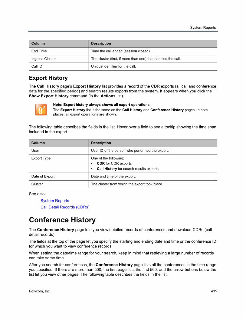
System Reports
Polycom, Inc. 435
Export HistoryThe Call History page’s Export History list provides a record of the CDR exports (all call and conference data for the specified period) and search results exports from the system. It appears when you click the Show Export History command (in the Actions list).
The following table describes the fields in the list. Hover over a field to see a tooltip showing the time span included in the export.
See also:
System Reports
Call Detail Records (CDRs)
Conference HistoryThe Conference History page lets you view detailed records of conferences and download CDRs (call detail records).
The fields at the top of the page let you specify the starting and ending date and time or the conference ID for which you want to view conference records.
When setting the date/time range for your search, keep in mind that retrieving a large number of records can take some time.
After you search for conferences, the Conference History page lists all the conferences in the time range you specified. If there are more than 500, the first page lists the first 500, and the arrow buttons below the list let you view other pages. The following table describes the fields in the list.
End Time Time the call ended (session closed).
Ingress Cluster The cluster (first, if more than one) that handled the call.
Call ID Unique identifier for the call.
Note: Export history always shows all export operations
The Export History list is the same on the Call History and Conference History pages. In both places, all export operations are shown.
Column Description
User User ID of the person who performed the export.
Export Type One of the following:
• CDR for CDR exports
• Call History for search results exports
Date of Export Date and time of the export.
Cluster The cluster from which the export took place.
Column Description
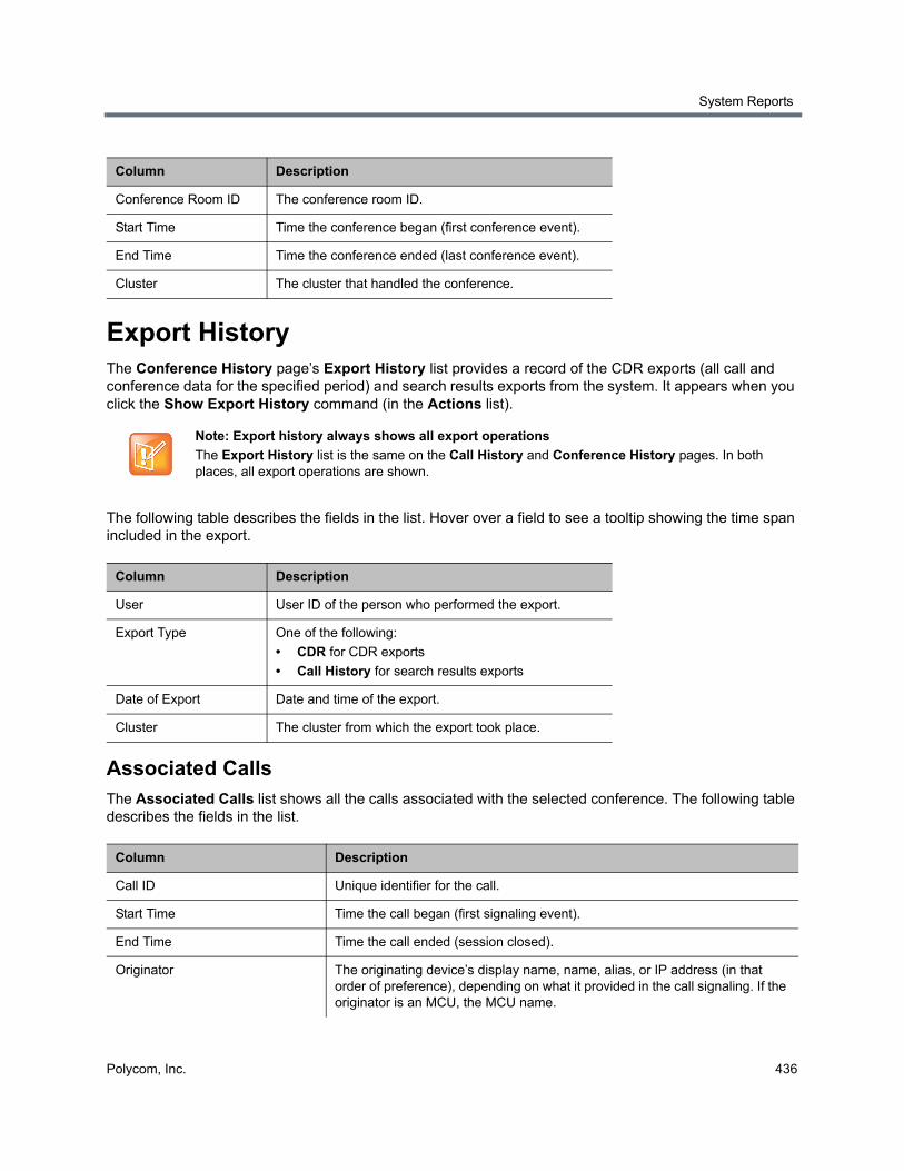
System Reports
Polycom, Inc. 436
Export HistoryThe Conference History page’s Export History list provides a record of the CDR exports (all call and conference data for the specified period) and search results exports from the system. It appears when you click the Show Export History command (in the Actions list).
The following table describes the fields in the list. Hover over a field to see a tooltip showing the time span included in the export.
Associated CallsThe Associated Calls list shows all the calls associated with the selected conference. The following table describes the fields in the list.
Column Description
Conference Room ID The conference room ID.
Start Time Time the conference began (first conference event).
End Time Time the conference ended (last conference event).
Cluster The cluster that handled the conference.
Note: Export history always shows all export operations
The Export History list is the same on the Call History and Conference History pages. In both places, all export operations are shown.
Column Description
User User ID of the person who performed the export.
Export Type One of the following:
• CDR for CDR exports
• Call History for search results exports
Date of Export Date and time of the export.
Cluster The cluster from which the export took place.
Column Description
Call ID Unique identifier for the call.
Start Time Time the call began (first signaling event).
End Time Time the call ended (session closed).
Originator The originating device’s display name, name, alias, or IP address (in that order of preference), depending on what it provided in the call signaling. If the originator is an MCU, the MCU name.
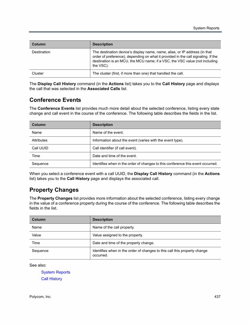
System Reports
Polycom, Inc. 437
The Display Call History command (in the Actions list) takes you to the Call History page and displays the call that was selected in the Associated Calls list.
Conference EventsThe Conference Events list provides much more detail about the selected conference, listing every state change and call event in the course of the conference. The following table describes the fields in the list.
When you select a conference event with a call UUID, the Display Call History command (in the Actions list) takes you to the Call History page and displays the associated call.
Property ChangesThe Property Changes list provides more information about the selected conference, listing every change in the value of a conference property during the course of the conference. The following table describes the fields in the list.
See also:
System Reports
Call History
Destination The destination device’s display name, name, alias, or IP address (in that order of preference), depending on what it provided in the call signaling. If the destination is an MCU, the MCU name; if a VSC, the VSC value (not including the VSC).
Cluster The cluster (first, if more than one) that handled the call.
Column Description
Name Name of the event.
Attributes Information about the event (varies with the event type).
Call UUID Call identifier (if call event).
Time Date and time of the event.
Sequence Identifies when in the order of changes to this conference this event occurred.
Column Description
Name Name of the call property.
Value Value assigned to the property.
Time Date and time of the property change.
Sequence Identifies when in the order of changes to this call this property change occurred.
Column Description

System Reports
Polycom, Inc. 438
Call Detail Records (CDRs)In addition to the online call and conference history reports, the Polycom RealPresence DMA system generates call detail records (CDRs) for all calls and conferences, which you can download.
The procedure for exporting CDRs and the record layouts are described in the sections that follow.
Exporting CDR DataFrom the Call History or Conference History page, you can use the Export CDR Data command to download call detail records (CDRs) for the time period you specify.
To download CDRs
1 Go to Reports > Call History (or Conference History).
2 In the Actions list, click Export CDR Data.
3 In the Export Time Frame dialog, set the Start Date and time and the End Date and time you want to include.
The defaults provide all CDR data for the current day. Times and dates are in the time zone of your browser.
4 Click OK.
A Save dialog prompts you to select a location for the downloaded file. The default filename is cdrExport.zip, but you can change that.
5 Choose a path and filename for the CDR file and click Save.
The File Download dialog shows the progress.
6 When the download is complete, click Close.
After you unzip the download file, you can open the two CSV files it contains (one for calls and one for conferences) with Microsoft Excel or another spreadsheet application. The CSV files contain a line for each call or conference that ended during the selected time frame.
The ZIP file also includes a text file that contains a single line specifying:
● The number of calls in the call CDR file.
● The number conferences in the conference CDR file.
● The clusters whose calls and conferences are included in the CDR file.
● The clusters whose calls and conferences are excluded from the CDR file because those clusters were not reachable when the CDR export was generated.
Call Record LayoutsThe following table describes the fields in the call records.
Field values are enclosed in double quotes if:
● They begin or end with a space or tab (" value").
● They contain a comma ("Smith, John").
● They contain a double quote. In that case each double quote is also preceded by a double quote ("William ""Bill"" Smith").
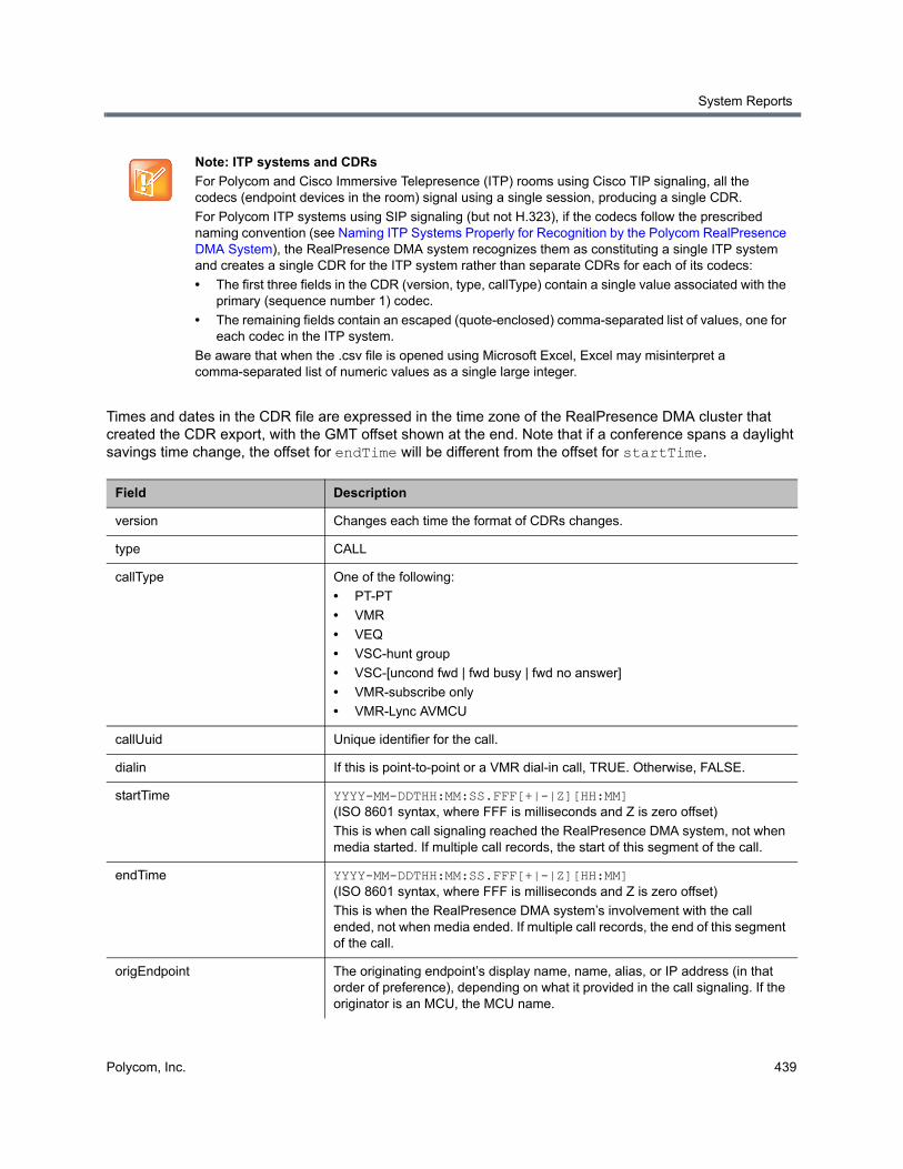
System Reports
Polycom, Inc. 439
Times and dates in the CDR file are expressed in the time zone of the RealPresence DMA cluster that created the CDR export, with the GMT offset shown at the end. Note that if a conference spans a daylight savings time change, the offset for endTime will be different from the offset for startTime.
Note: ITP systems and CDRs
For Polycom and Cisco Immersive Telepresence (ITP) rooms using Cisco TIP signaling, all the codecs (endpoint devices in the room) signal using a single session, producing a single CDR.
For Polycom ITP systems using SIP signaling (but not H.323), if the codecs follow the prescribed naming convention (see Naming ITP Systems Properly for Recognition by the Polycom RealPresence DMA System), the RealPresence DMA system recognizes them as constituting a single ITP system and creates a single CDR for the ITP system rather than separate CDRs for each of its codecs:
• The first three fields in the CDR (version, type, callType) contain a single value associated with the primary (sequence number 1) codec.
• The remaining fields contain an escaped (quote-enclosed) comma-separated list of values, one for each codec in the ITP system.
Be aware that when the .csv file is opened using Microsoft Excel, Excel may misinterpret a comma-separated list of numeric values as a single large integer.
Field Description
version Changes each time the format of CDRs changes.
type CALL
callType One of the following:
• PT-PT
• VMR
• VEQ
• VSC-hunt group
• VSC-[uncond fwd | fwd busy | fwd no answer]
• VMR-subscribe only
• VMR-Lync AVMCU
callUuid Unique identifier for the call.
dialin If this is point-to-point or a VMR dial-in call, TRUE. Otherwise, FALSE.
startTime YYYY-MM-DDTHH:MM:SS.FFF[+|-|Z][HH:MM] (ISO 8601 syntax, where FFF is milliseconds and Z is zero offset)
This is when call signaling reached the RealPresence DMA system, not when media started. If multiple call records, the start of this segment of the call.
endTime YYYY-MM-DDTHH:MM:SS.FFF[+|-|Z][HH:MM] (ISO 8601 syntax, where FFF is milliseconds and Z is zero offset)
This is when the RealPresence DMA system’s involvement with the call ended, not when media ended. If multiple call records, the end of this segment of the call.
origEndpoint The originating endpoint’s display name, name, alias, or IP address (in that order of preference), depending on what it provided in the call signaling. If the originator is an MCU, the MCU name.
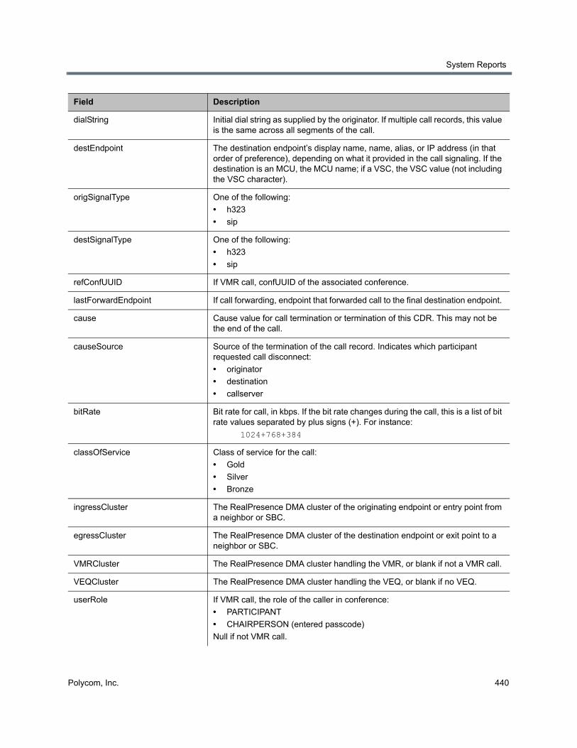
System Reports
Polycom, Inc. 440
dialString Initial dial string as supplied by the originator. If multiple call records, this value is the same across all segments of the call.
destEndpoint The destination endpoint’s display name, name, alias, or IP address (in that order of preference), depending on what it provided in the call signaling. If the destination is an MCU, the MCU name; if a VSC, the VSC value (not including the VSC character).
origSignalType One of the following:
• h323
• sip
destSignalType One of the following:
• h323
• sip
refConfUUID If VMR call, confUUID of the associated conference.
lastForwardEndpoint If call forwarding, endpoint that forwarded call to the final destination endpoint.
cause Cause value for call termination or termination of this CDR. This may not be the end of the call.
causeSource Source of the termination of the call record. Indicates which participant requested call disconnect:
• originator
• destination
• callserver
bitRate Bit rate for call, in kbps. If the bit rate changes during the call, this is a list of bit rate values separated by plus signs (+). For instance:
1024+768+384
classOfService Class of service for the call:
• Gold
• Silver
• Bronze
ingressCluster The RealPresence DMA cluster of the originating endpoint or entry point from a neighbor or SBC.
egressCluster The RealPresence DMA cluster of the destination endpoint or exit point to a neighbor or SBC.
VMRCluster The RealPresence DMA cluster handling the VMR, or blank if not a VMR call.
VEQCluster The RealPresence DMA cluster handling the VEQ, or blank if no VEQ.
userRole If VMR call, the role of the caller in conference:
• PARTICIPANT
• CHAIRPERSON (entered passcode)
Null if not VMR call.
Field Description
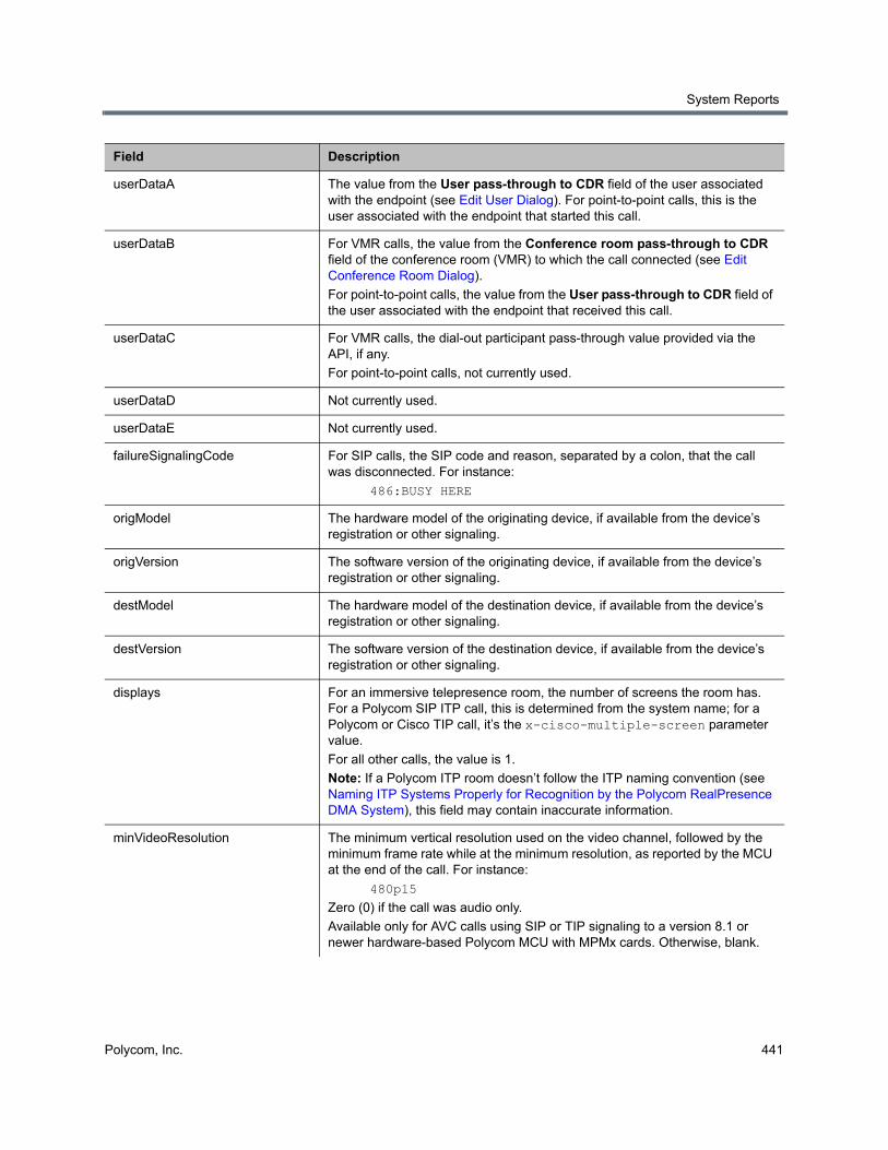
System Reports
Polycom, Inc. 441
userDataA The value from the User pass-through to CDR field of the user associated with the endpoint (see Edit User Dialog). For point-to-point calls, this is the user associated with the endpoint that started this call.
userDataB For VMR calls, the value from the Conference room pass-through to CDR field of the conference room (VMR) to which the call connected (see Edit Conference Room Dialog).
For point-to-point calls, the value from the User pass-through to CDR field of the user associated with the endpoint that received this call.
userDataC For VMR calls, the dial-out participant pass-through value provided via the API, if any.
For point-to-point calls, not currently used.
userDataD Not currently used.
userDataE Not currently used.
failureSignalingCode For SIP calls, the SIP code and reason, separated by a colon, that the call was disconnected. For instance:
486:BUSY HERE
origModel The hardware model of the originating device, if available from the device’s registration or other signaling.
origVersion The software version of the originating device, if available from the device’s registration or other signaling.
destModel The hardware model of the destination device, if available from the device’s registration or other signaling.
destVersion The software version of the destination device, if available from the device’s registration or other signaling.
displays For an immersive telepresence room, the number of screens the room has. For a Polycom SIP ITP call, this is determined from the system name; for a Polycom or Cisco TIP call, it’s the x-cisco-multiple-screen parameter value.
For all other calls, the value is 1.
Note: If a Polycom ITP room doesn’t follow the ITP naming convention (see Naming ITP Systems Properly for Recognition by the Polycom RealPresence DMA System), this field may contain inaccurate information.
minVideoResolution The minimum vertical resolution used on the video channel, followed by the minimum frame rate while at the minimum resolution, as reported by the MCU at the end of the call. For instance:
480p15
Zero (0) if the call was audio only.
Available only for AVC calls using SIP or TIP signaling to a version 8.1 or newer hardware-based Polycom MCU with MPMx cards. Otherwise, blank.
Field Description
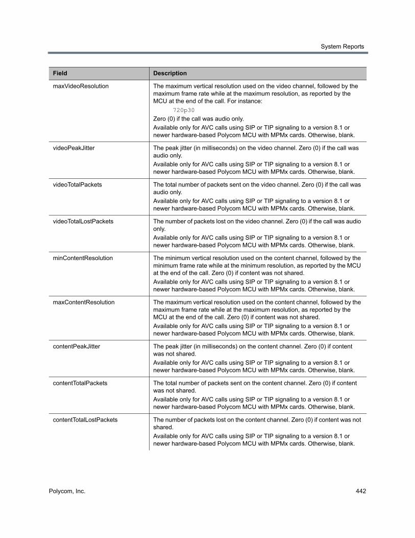
System Reports
Polycom, Inc. 442
maxVideoResolution The maximum vertical resolution used on the video channel, followed by the maximum frame rate while at the maximum resolution, as reported by the MCU at the end of the call. For instance:
720p30
Zero (0) if the call was audio only.
Available only for AVC calls using SIP or TIP signaling to a version 8.1 or newer hardware-based Polycom MCU with MPMx cards. Otherwise, blank.
videoPeakJitter The peak jitter (in milliseconds) on the video channel. Zero (0) if the call was audio only.
Available only for AVC calls using SIP or TIP signaling to a version 8.1 or newer hardware-based Polycom MCU with MPMx cards. Otherwise, blank.
videoTotalPackets The total number of packets sent on the video channel. Zero (0) if the call was audio only.
Available only for AVC calls using SIP or TIP signaling to a version 8.1 or newer hardware-based Polycom MCU with MPMx cards. Otherwise, blank.
videoTotalLostPackets The number of packets lost on the video channel. Zero (0) if the call was audio only.
Available only for AVC calls using SIP or TIP signaling to a version 8.1 or newer hardware-based Polycom MCU with MPMx cards. Otherwise, blank.
minContentResolution The minimum vertical resolution used on the content channel, followed by the minimum frame rate while at the minimum resolution, as reported by the MCU at the end of the call. Zero (0) if content was not shared.
Available only for AVC calls using SIP or TIP signaling to a version 8.1 or newer hardware-based Polycom MCU with MPMx cards. Otherwise, blank.
maxContentResolution The maximum vertical resolution used on the content channel, followed by the maximum frame rate while at the maximum resolution, as reported by the MCU at the end of the call. Zero (0) if content was not shared.
Available only for AVC calls using SIP or TIP signaling to a version 8.1 or newer hardware-based Polycom MCU with MPMx cards. Otherwise, blank.
contentPeakJitter The peak jitter (in milliseconds) on the content channel. Zero (0) if content was not shared.
Available only for AVC calls using SIP or TIP signaling to a version 8.1 or newer hardware-based Polycom MCU with MPMx cards. Otherwise, blank.
contentTotalPackets The total number of packets sent on the content channel. Zero (0) if content was not shared.
Available only for AVC calls using SIP or TIP signaling to a version 8.1 or newer hardware-based Polycom MCU with MPMx cards. Otherwise, blank.
contentTotalLostPackets The number of packets lost on the content channel. Zero (0) if content was not shared.
Available only for AVC calls using SIP or TIP signaling to a version 8.1 or newer hardware-based Polycom MCU with MPMx cards. Otherwise, blank.
Field Description
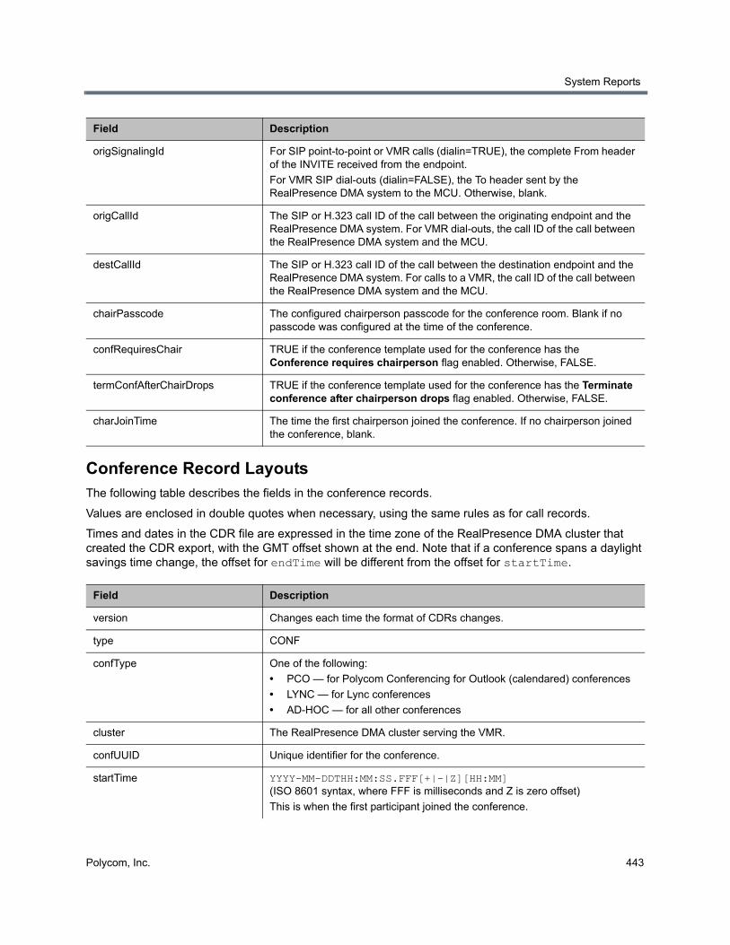
System Reports
Polycom, Inc. 443
Conference Record LayoutsThe following table describes the fields in the conference records.
Values are enclosed in double quotes when necessary, using the same rules as for call records.
Times and dates in the CDR file are expressed in the time zone of the RealPresence DMA cluster that created the CDR export, with the GMT offset shown at the end. Note that if a conference spans a daylight savings time change, the offset for endTime will be different from the offset for startTime.
origSignalingId For SIP point-to-point or VMR calls (dialin=TRUE), the complete From header of the INVITE received from the endpoint.
For VMR SIP dial-outs (dialin=FALSE), the To header sent by the RealPresence DMA system to the MCU. Otherwise, blank.
origCallId The SIP or H.323 call ID of the call between the originating endpoint and the RealPresence DMA system. For VMR dial-outs, the call ID of the call between the RealPresence DMA system and the MCU.
destCallId The SIP or H.323 call ID of the call between the destination endpoint and the RealPresence DMA system. For calls to a VMR, the call ID of the call between the RealPresence DMA system and the MCU.
chairPasscode The configured chairperson passcode for the conference room. Blank if no passcode was configured at the time of the conference.
confRequiresChair TRUE if the conference template used for the conference has the Conference requires chairperson flag enabled. Otherwise, FALSE.
termConfAfterChairDrops TRUE if the conference template used for the conference has the Terminate conference after chairperson drops flag enabled. Otherwise, FALSE.
charJoinTime The time the first chairperson joined the conference. If no chairperson joined the conference, blank.
Field Description
version Changes each time the format of CDRs changes.
type CONF
confType One of the following:
• PCO — for Polycom Conferencing for Outlook (calendared) conferences
• LYNC — for Lync conferences
• AD-HOC — for all other conferences
cluster The RealPresence DMA cluster serving the VMR.
confUUID Unique identifier for the conference.
startTime YYYY-MM-DDTHH:MM:SS.FFF[+|-|Z][HH:MM] (ISO 8601 syntax, where FFF is milliseconds and Z is zero offset)
This is when the first participant joined the conference.
Field Description
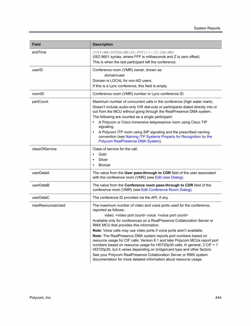
System Reports
Polycom, Inc. 444
endTime YYYY-MM-DDTHH:MM:SS.FFF[+|-|Z][HH:MM] (ISO 8601 syntax, where FFF is milliseconds and Z is zero offset)
This is when the last participant left the conference.
userID Conference room (VMR) owner, shown as:
domain\user
Domain is LOCAL for non-AD users.
If this is a Lync conference, this field is empty.
roomID Conference room (VMR) number or Lync conference ID.
partCount Maximum number of concurrent calls in the conference (high water mark).
Doesn’t include audio-only IVR dial-outs or participants dialed directly into or out from the MCU without going through the RealPresence DMA system.
The following are counted as a single participant:
• A Polycom or Cisco immersive telepresence room using Cisco TIP signaling.
• A Polycom ITP room using SIP signaling and the prescribed naming convention (see Naming ITP Systems Properly for Recognition by the Polycom RealPresence DMA System).
classOfService Class of service for the call:
• Gold
• Silver
• Bronze
userDataA The value from the User pass-through to CDR field of the user associated with the conference room (VMR) (see Edit User Dialog).
userDataB The value from the Conference room pass-through to CDR field of the conference room (VMR) (see Edit Conference Room Dialog).
userDataC The conference ID provided via the API, if any.
maxResourcesUsed The maximum number of video and voice ports used for the conference, reported as follows:
video: <video port count> voice: <voice port count>
Available only for conferences on a RealPresence Collaboration Server or RMX MCU that provides this information.
Note: Voice calls may use video ports if voice ports aren’t available.
Note: The RealPresence DMA system reports port numbers based on resource usage for CIF calls. Version 8.1 and later Polycom MCUs report port numbers based on resource usage for HD720p30 calls. In general, 3 CIF = 1 HD720p30, but it varies depending on bridge/card type and other factors.
See your Polycom RealPresence Collaboration Server or RMX system documentation for more detailed information about resource usage.
Field Description
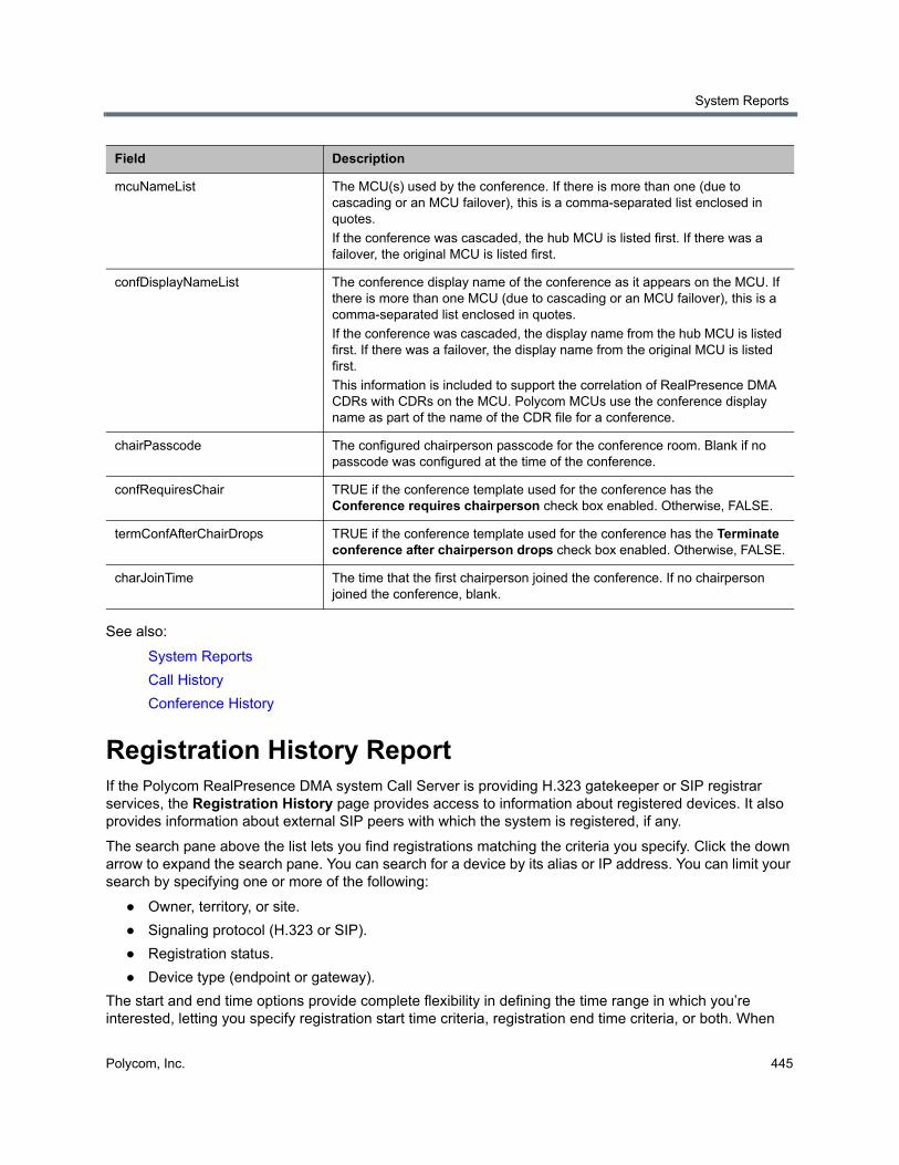
System Reports
Polycom, Inc. 445
See also:
System Reports
Call History
Conference History
Registration History ReportIf the Polycom RealPresence DMA system Call Server is providing H.323 gatekeeper or SIP registrar services, the Registration History page provides access to information about registered devices. It also provides information about external SIP peers with which the system is registered, if any.
The search pane above the list lets you find registrations matching the criteria you specify. Click the down arrow to expand the search pane. You can search for a device by its alias or IP address. You can limit your search by specifying one or more of the following:
● Owner, territory, or site.
● Signaling protocol (H.323 or SIP).
● Registration status.
● Device type (endpoint or gateway).
The start and end time options provide complete flexibility in defining the time range in which you’re interested, letting you specify registration start time criteria, registration end time criteria, or both. When
mcuNameList The MCU(s) used by the conference. If there is more than one (due to cascading or an MCU failover), this is a comma-separated list enclosed in quotes.
If the conference was cascaded, the hub MCU is listed first. If there was a failover, the original MCU is listed first.
confDisplayNameList The conference display name of the conference as it appears on the MCU. If there is more than one MCU (due to cascading or an MCU failover), this is a comma-separated list enclosed in quotes.
If the conference was cascaded, the display name from the hub MCU is listed first. If there was a failover, the display name from the original MCU is listed first.
This information is included to support the correlation of RealPresence DMA CDRs with CDRs on the MCU. Polycom MCUs use the conference display name as part of the name of the CDR file for a conference.
chairPasscode The configured chairperson passcode for the conference room. Blank if no passcode was configured at the time of the conference.
confRequiresChair TRUE if the conference template used for the conference has the Conference requires chairperson check box enabled. Otherwise, FALSE.
termConfAfterChairDrops TRUE if the conference template used for the conference has the Terminate conference after chairperson drops check box enabled. Otherwise, FALSE.
charJoinTime The time that the first chairperson joined the conference. If no chairperson joined the conference, blank.
Field Description
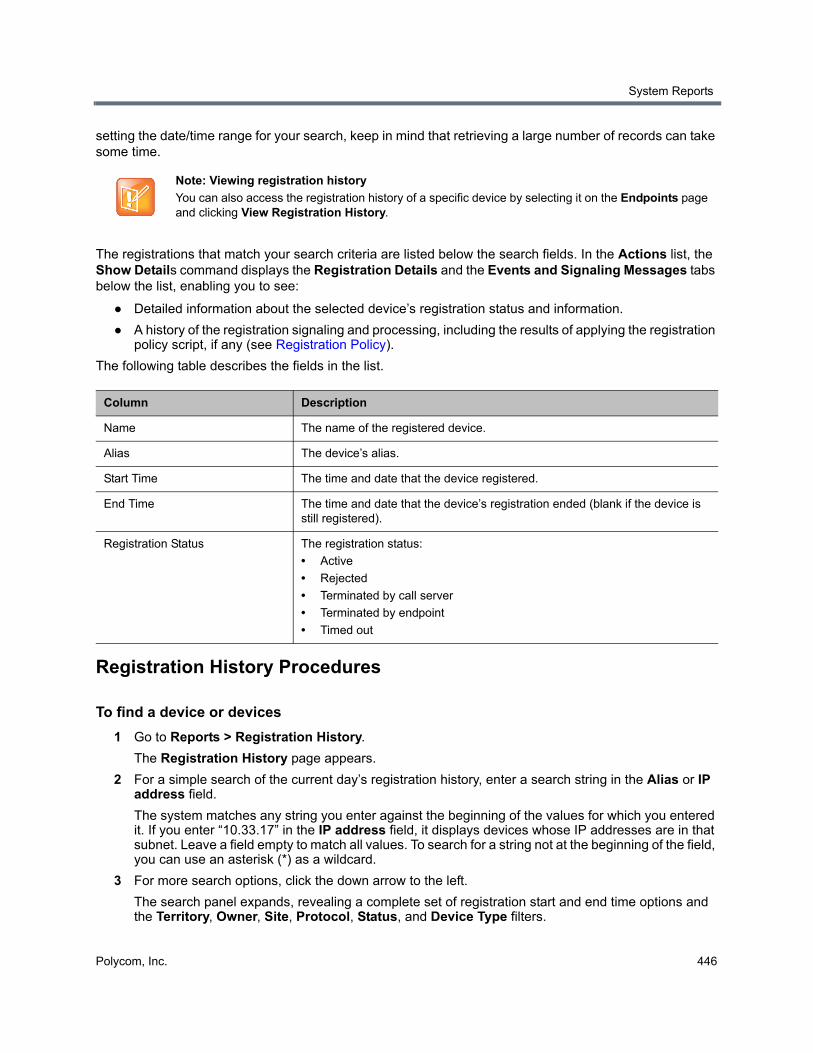
System Reports
Polycom, Inc. 446
setting the date/time range for your search, keep in mind that retrieving a large number of records can take some time.
The registrations that match your search criteria are listed below the search fields. In the Actions list, the Show Details command displays the Registration Details and the Events and Signaling Messages tabs below the list, enabling you to see:
● Detailed information about the selected device’s registration status and information.
● A history of the registration signaling and processing, including the results of applying the registration policy script, if any (see Registration Policy).
The following table describes the fields in the list.
Registration History Procedures
To find a device or devices
1 Go to Reports > Registration History.
The Registration History page appears.
2 For a simple search of the current day’s registration history, enter a search string in the Alias or IP address field.
The system matches any string you enter against the beginning of the values for which you entered it. If you enter “10.33.17” in the IP address field, it displays devices whose IP addresses are in that subnet. Leave a field empty to match all values. To search for a string not at the beginning of the field, you can use an asterisk (*) as a wildcard.
3 For more search options, click the down arrow to the left.
The search panel expands, revealing a complete set of registration start and end time options and the Territory, Owner, Site, Protocol, Status, and Device Type filters.
Note: Viewing registration history
You can also access the registration history of a specific device by selecting it on the Endpoints page and clicking View Registration History.
Column Description
Name The name of the registered device.
Alias The device’s alias.
Start Time The time and date that the device registered.
End Time The time and date that the device’s registration ended (blank if the device is still registered).
Registration Status The registration status:
• Active
• Rejected
• Terminated by call server
• Terminated by endpoint
• Timed out
System Reports
Polycom, Inc. 447
4 Optionally, specify a start or end time range and any filter criteria you want to use. Then click Search.
The system displays the devices matching your search criteria.
See also:
System Reports
Call History
Conference History
Active Directory Integration ReportIf the Polycom RealPresence DMA system is integrated with your Active Directory, it reads the Active Directory daily to refresh the information in its cache. It also rereads the directory whenever you update the directory integration settings (Admin > Integrations > Microsoft Active Directory).
For each cache update, the system generates an integration report.
The Active Directory Integration page reports the status for the last cache update, shows contact results for each domain in the forest, and lists any groups for which it was unable to retrieve membership information.
The following table describes the information displayed at the top of the page and the fields in the two lists.
Note: Enterprise vs. local users
You must be an enterprise user (with the appropriate user role assignments) to see the Active Directory integration report. A local user can’t access this page, regardless of user roles.
Field Description
Status OK indicates that the cluster successfully connected to the Active Directory during the last update. A padlock indicates that the connection was encrypted.
User and group cache Shows the state of the cluster’s cache of directory data and when it was last updated.
Server name The Active Directory server from which the Polycom RealPresence DMA system retrieved the directory data it needs.
Connected to global catalog Indicates whether the cluster connected to a global catalog server. If it did, but some attributes were not in the global catalog, that’s noted. Those attributes were retrieved from the domain controllers, and the results of that process are reported in the All Domains list below.
Forest root DN Shows the distinguished name of the Active Directory forest root domain.
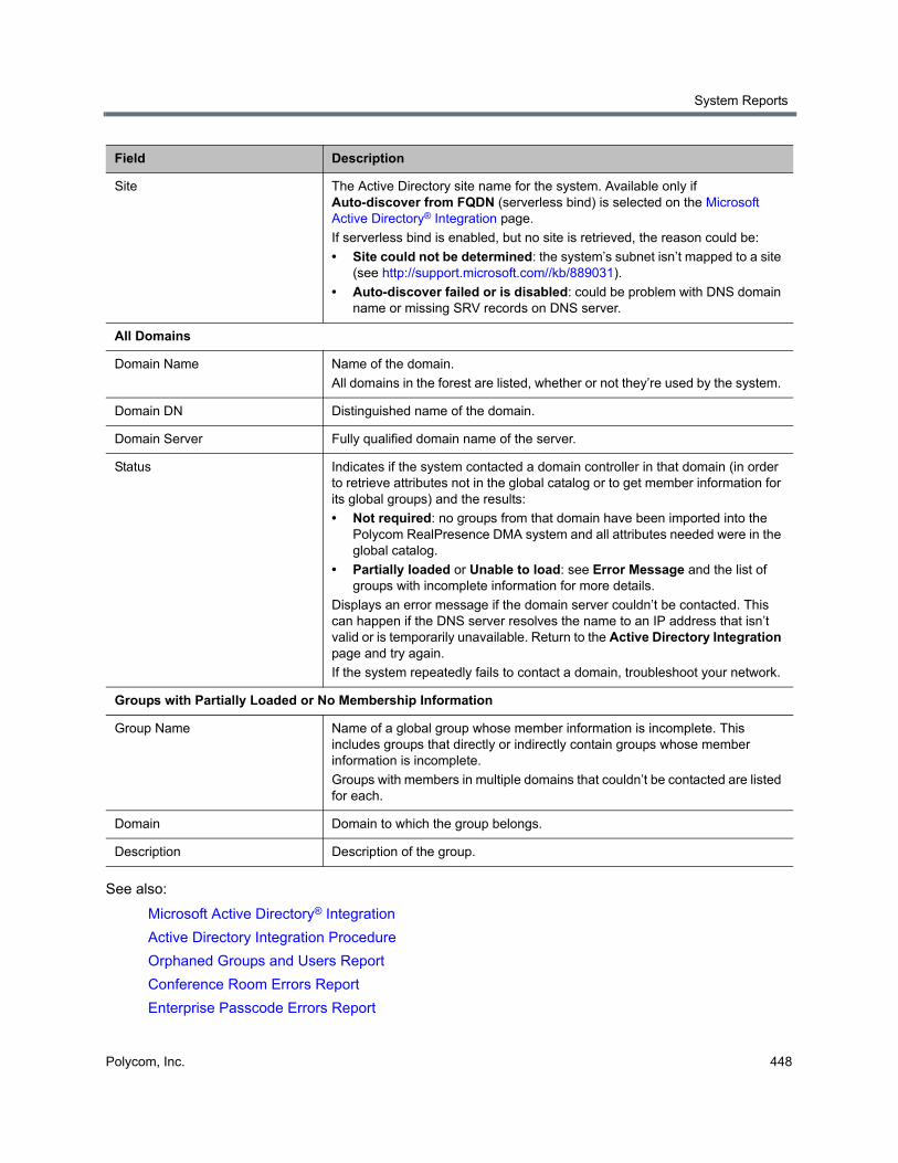
System Reports
Polycom, Inc. 448
See also:
Microsoft Active Directory® Integration
Active Directory Integration Procedure
Orphaned Groups and Users Report
Conference Room Errors Report
Enterprise Passcode Errors Report
Site The Active Directory site name for the system. Available only if Auto-discover from FQDN (serverless bind) is selected on the Microsoft Active Directory® Integration page.
If serverless bind is enabled, but no site is retrieved, the reason could be:
• Site could not be determined: the system’s subnet isn’t mapped to a site (see http://support.microsoft.com//kb/889031).
• Auto-discover failed or is disabled: could be problem with DNS domain name or missing SRV records on DNS server.
All Domains
Domain Name Name of the domain.
All domains in the forest are listed, whether or not they’re used by the system.
Domain DN Distinguished name of the domain.
Domain Server Fully qualified domain name of the server.
Status Indicates if the system contacted a domain controller in that domain (in order to retrieve attributes not in the global catalog or to get member information for its global groups) and the results:
• Not required: no groups from that domain have been imported into the Polycom RealPresence DMA system and all attributes needed were in the global catalog.
• Partially loaded or Unable to load: see Error Message and the list of groups with incomplete information for more details.
Displays an error message if the domain server couldn’t be contacted. This can happen if the DNS server resolves the name to an IP address that isn’t valid or is temporarily unavailable. Return to the Active Directory Integration page and try again.
If the system repeatedly fails to contact a domain, troubleshoot your network.
Groups with Partially Loaded or No Membership Information
Group Name Name of a global group whose member information is incomplete. This includes groups that directly or indirectly contain groups whose member information is incomplete.
Groups with members in multiple domains that couldn’t be contacted are listed for each.
Domain Domain to which the group belongs.
Description Description of the group.
Field Description
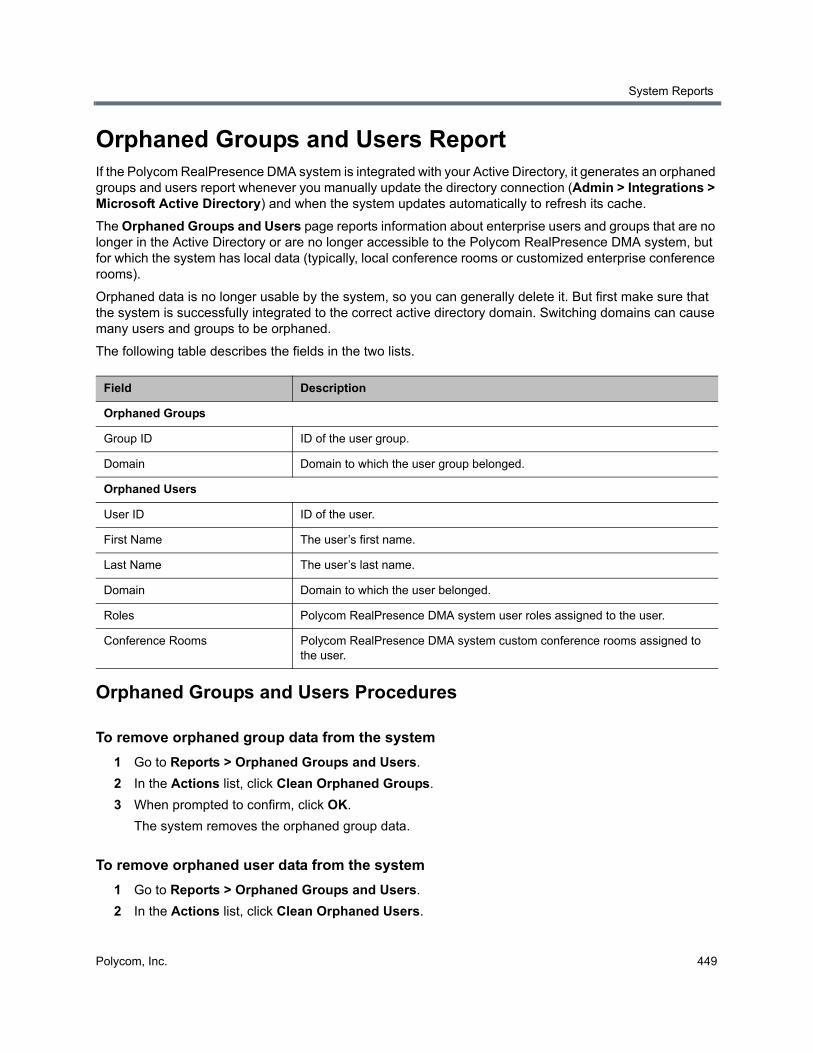
System Reports
Polycom, Inc. 449
Orphaned Groups and Users ReportIf the Polycom RealPresence DMA system is integrated with your Active Directory, it generates an orphaned groups and users report whenever you manually update the directory connection (Admin > Integrations > Microsoft Active Directory) and when the system updates automatically to refresh its cache.
The Orphaned Groups and Users page reports information about enterprise users and groups that are no longer in the Active Directory or are no longer accessible to the Polycom RealPresence DMA system, but for which the system has local data (typically, local conference rooms or customized enterprise conference rooms).
Orphaned data is no longer usable by the system, so you can generally delete it. But first make sure that the system is successfully integrated to the correct active directory domain. Switching domains can cause many users and groups to be orphaned.
The following table describes the fields in the two lists.
Orphaned Groups and Users Procedures
To remove orphaned group data from the system
1 Go to Reports > Orphaned Groups and Users.
2 In the Actions list, click Clean Orphaned Groups.
3 When prompted to confirm, click OK.
The system removes the orphaned group data.
To remove orphaned user data from the system
1 Go to Reports > Orphaned Groups and Users.
2 In the Actions list, click Clean Orphaned Users.
Field Description
Orphaned Groups
Group ID ID of the user group.
Domain Domain to which the user group belonged.
Orphaned Users
User ID ID of the user.
First Name The user’s first name.
Last Name The user’s last name.
Domain Domain to which the user belonged.
Roles Polycom RealPresence DMA system user roles assigned to the user.
Conference Rooms Polycom RealPresence DMA system custom conference rooms assigned to the user.
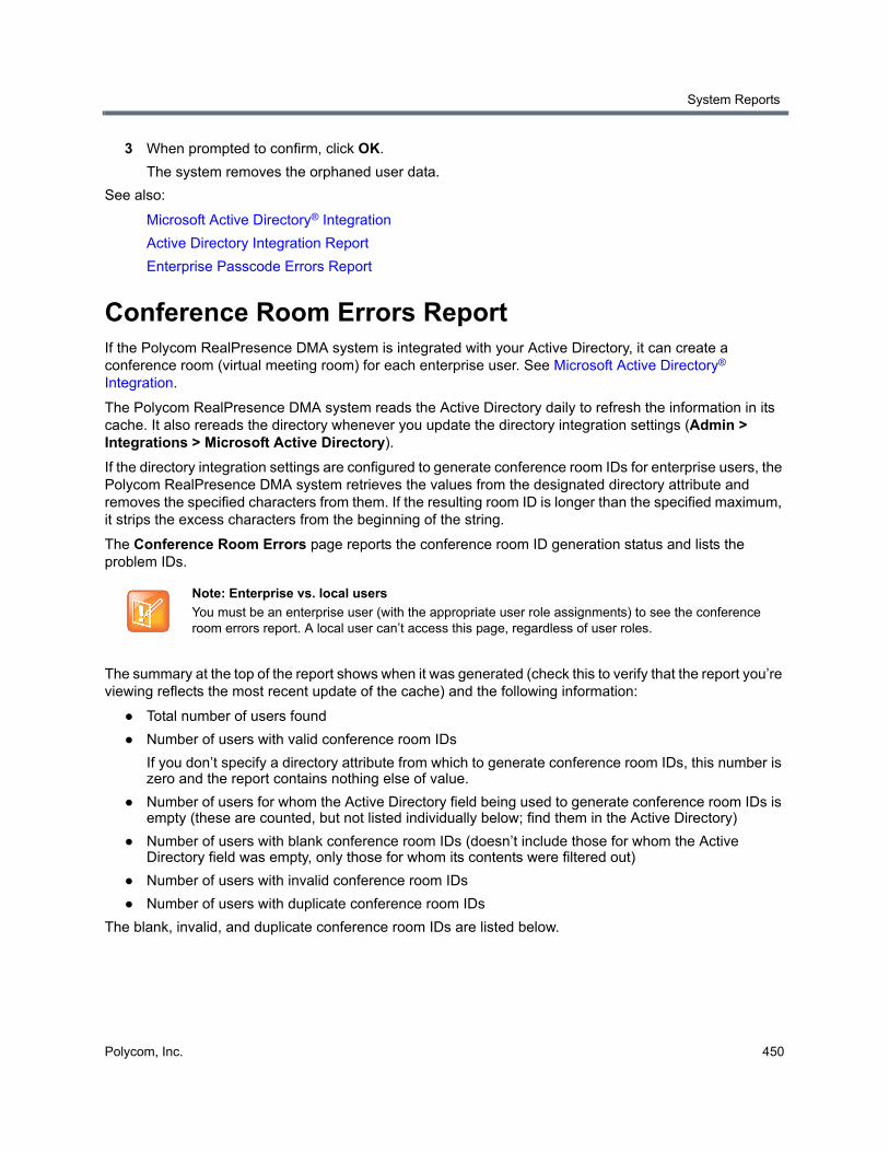
System Reports
Polycom, Inc. 450
3 When prompted to confirm, click OK.
The system removes the orphaned user data.
See also:
Microsoft Active Directory® Integration
Active Directory Integration Report
Enterprise Passcode Errors Report
Conference Room Errors ReportIf the Polycom RealPresence DMA system is integrated with your Active Directory, it can create a conference room (virtual meeting room) for each enterprise user. See Microsoft Active Directory® Integration.
The Polycom RealPresence DMA system reads the Active Directory daily to refresh the information in its cache. It also rereads the directory whenever you update the directory integration settings (Admin > Integrations > Microsoft Active Directory).
If the directory integration settings are configured to generate conference room IDs for enterprise users, the Polycom RealPresence DMA system retrieves the values from the designated directory attribute and removes the specified characters from them. If the resulting room ID is longer than the specified maximum, it strips the excess characters from the beginning of the string.
The Conference Room Errors page reports the conference room ID generation status and lists the problem IDs.
The summary at the top of the report shows when it was generated (check this to verify that the report you’re viewing reflects the most recent update of the cache) and the following information:
● Total number of users found
● Number of users with valid conference room IDs
If you don’t specify a directory attribute from which to generate conference room IDs, this number is zero and the report contains nothing else of value.
● Number of users for whom the Active Directory field being used to generate conference room IDs is empty (these are counted, but not listed individually below; find them in the Active Directory)
● Number of users with blank conference room IDs (doesn’t include those for whom the Active Directory field was empty, only those for whom its contents were filtered out)
● Number of users with invalid conference room IDs
● Number of users with duplicate conference room IDs
The blank, invalid, and duplicate conference room IDs are listed below.
Note: Enterprise vs. local users
You must be an enterprise user (with the appropriate user role assignments) to see the conference room errors report. A local user can’t access this page, regardless of user roles.
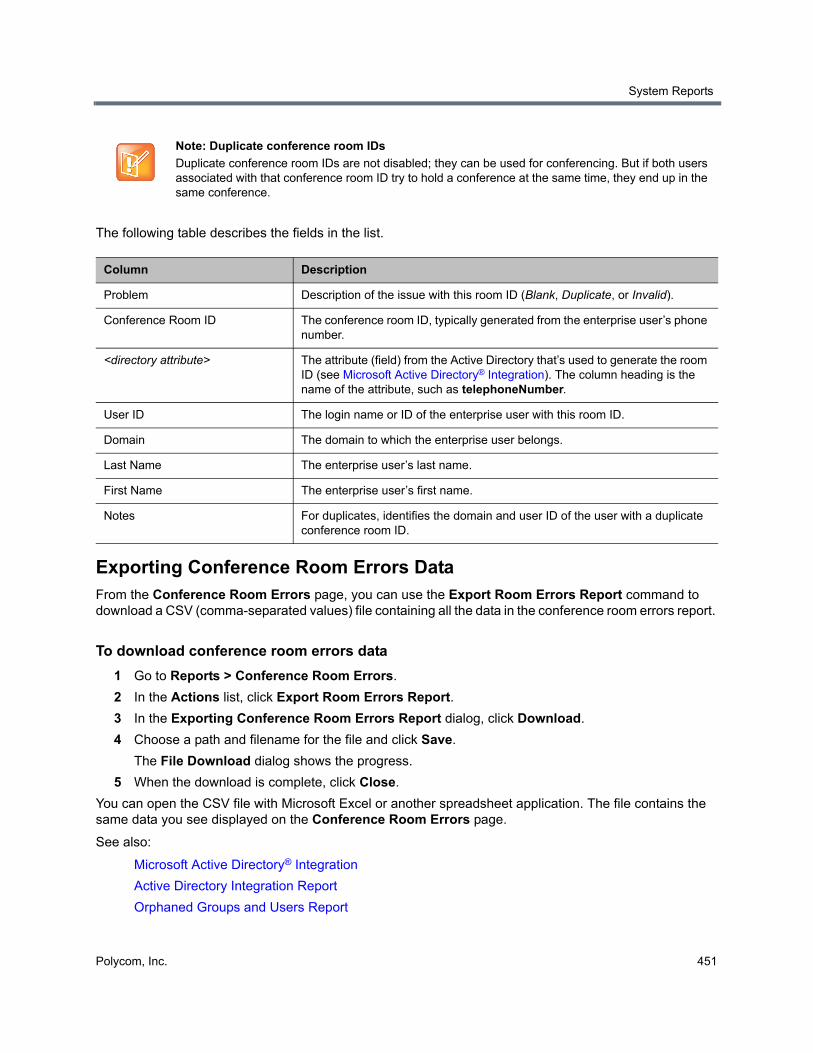
System Reports
Polycom, Inc. 451
The following table describes the fields in the list.
Exporting Conference Room Errors DataFrom the Conference Room Errors page, you can use the Export Room Errors Report command to download a CSV (comma-separated values) file containing all the data in the conference room errors report.
To download conference room errors data
1 Go to Reports > Conference Room Errors.
2 In the Actions list, click Export Room Errors Report.
3 In the Exporting Conference Room Errors Report dialog, click Download.
4 Choose a path and filename for the file and click Save.
The File Download dialog shows the progress.
5 When the download is complete, click Close.
You can open the CSV file with Microsoft Excel or another spreadsheet application. The file contains the same data you see displayed on the Conference Room Errors page.
See also:
Microsoft Active Directory® Integration
Active Directory Integration Report
Orphaned Groups and Users Report
Note: Duplicate conference room IDs
Duplicate conference room IDs are not disabled; they can be used for conferencing. But if both users associated with that conference room ID try to hold a conference at the same time, they end up in the same conference.
Column Description
Problem Description of the issue with this room ID (Blank, Duplicate, or Invalid).
Conference Room ID The conference room ID, typically generated from the enterprise user’s phone number.
<directory attribute> The attribute (field) from the Active Directory that’s used to generate the room ID (see Microsoft Active Directory® Integration). The column heading is the name of the attribute, such as telephoneNumber.
User ID The login name or ID of the enterprise user with this room ID.
Domain The domain to which the enterprise user belongs.
Last Name The enterprise user’s last name.
First Name The enterprise user’s first name.
Notes For duplicates, identifies the domain and user ID of the user with a duplicate conference room ID.
System Reports
Polycom, Inc. 452
Enterprise Passcode Errors ReportIf the Polycom RealPresence DMA system is integrated with your Active Directory, conference and chairperson passcodes for enterprise users can be maintained in the Active Directory. See Add Passcodes for Enterprise Users.
The Polycom RealPresence DMA system reads the Active Directory daily to refresh the information in its cache. It also rereads the directory whenever you update the directory integration settings (Admin > Integrations > Microsoft Active Directory).
If the directory integration settings are configured to generate passcodes for enterprise users, the Polycom RealPresence DMA system retrieves the values from the designated directory attributes and removes any non-numeric characters from them. If the resulting numeric passcode is longer than the specified maximum for that passcode type, it strips the excess characters from the beginning of the string.
The Enterprise Passcode Errors page reports the passcode generation status and lists the users with passcode errors.
The summary at the top of the report shows when it was generated (check this to verify that the report you’re viewing reflects the most recent update of the cache), the directory server accessed, and the following information:
● Number of users in the directory
● Number of users with duplicate chairperson and conference passcodes
● Number of users with valid, invalid, and unassigned chairperson passcodes and the directory attribute on which they’re based, along with the number of users with locally overridden chairperson passcodes
● Number of users with valid, invalid, and unassigned conference passcodes and the directory attribute on which they’re based, along with the number of users with locally overridden conference passcodes
The users with invalid passcodes are listed below.
The following table describes the fields in the list.
Note: Enterprise vs. local users
You must be an enterprise user (with the appropriate user role assignments) to see the enterprise passcode errors report. A local user can’t access this page, regardless of user roles.
Note: Duplicate passcodes
For users with duplicate passcodes, the system ignores the conference passcode, but honors the chairperson passcode.
Column Description
Problem Indicates what the problem is: Chairperson, Conference, or Duplicate.
User ID The login name or ID of the enterprise user with this passcode error.
Domain The domain to which the enterprise user belongs.
Last Name The enterprise user’s last name.
System Reports
Polycom, Inc. 453
Exporting Enterprise Passcode Errors DataFrom the Conference Room Errors page, you can use the Export Enterprise Passcode Errors Report command to download a CSV (comma-separated values) file containing all the data in the enterprise passcode errors report.
To download enterprise passcode errors data
1 Go to Reports > Enterprise Passcode Errors.
2 In the Actions list, click Export Enterprise Passcode Errors Report.
3 In the Exporting Enterprise Passcode Errors Report dialog, click Download.
4 Choose a path and filename for the file and click Save.
The File Download dialog shows the progress.
5 When the download is complete, click Close.
You can open the CSV file with Microsoft Excel or another spreadsheet application. The file contains the same data you see displayed on the Enterprise Passcode Errors page.
See also:
Microsoft Active Directory® Integration
Add Passcodes for Enterprise Users
Active Directory Integration Report
Orphaned Groups and Users Report
Conference Room Errors Report
Network Usage ReportThe Network Usage page displays historical usage data about the video network and enables you to export that data.
The search criteria at the top of the page let you select:
● The start time and span/granularity you want included.
● The cluster, territory, or throttlepoint (site, site link, or subnet) whose data you want to see.
● The specific call, QoS, and bandwidth data you want to see.
The data matching the criteria you chose is graphed below.
First Name The enterprise user’s first name.
Notes For an invalid passcode, shows the generated value (after the system stripped non-numeric characters out of the attribute value and truncated it if necessary).
For duplicate chairperson and conference passcodes, shows the raw attribute value of each and the duplicate value generated (after stripping non-numeric characters and truncating if necessary).
Column Description
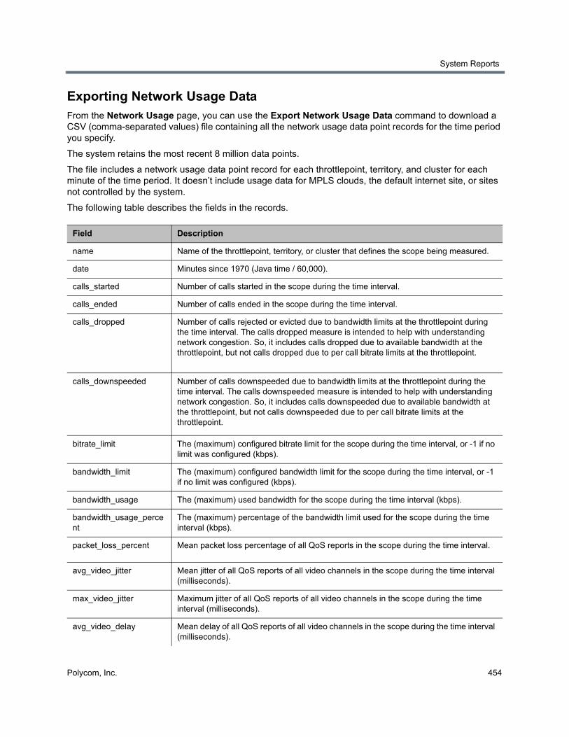
System Reports
Polycom, Inc. 454
Exporting Network Usage DataFrom the Network Usage page, you can use the Export Network Usage Data command to download a CSV (comma-separated values) file containing all the network usage data point records for the time period you specify.
The system retains the most recent 8 million data points.
The file includes a network usage data point record for each throttlepoint, territory, and cluster for each minute of the time period. It doesn’t include usage data for MPLS clouds, the default internet site, or sites not controlled by the system.
The following table describes the fields in the records.
Field Description
name Name of the throttlepoint, territory, or cluster that defines the scope being measured.
date Minutes since 1970 (Java time / 60,000).
calls_started Number of calls started in the scope during the time interval.
calls_ended Number of calls ended in the scope during the time interval.
calls_dropped Number of calls rejected or evicted due to bandwidth limits at the throttlepoint during the time interval. The calls dropped measure is intended to help with understanding network congestion. So, it includes calls dropped due to available bandwidth at the throttlepoint, but not calls dropped due to per call bitrate limits at the throttlepoint.
calls_downspeeded Number of calls downspeeded due to bandwidth limits at the throttlepoint during the time interval. The calls downspeeded measure is intended to help with understanding network congestion. So, it includes calls downspeeded due to available bandwidth at the throttlepoint, but not calls downspeeded due to per call bitrate limits at the throttlepoint.
bitrate_limit The (maximum) configured bitrate limit for the scope during the time interval, or -1 if no limit was configured (kbps).
bandwidth_limit The (maximum) configured bandwidth limit for the scope during the time interval, or -1 if no limit was configured (kbps).
bandwidth_usage The (maximum) used bandwidth for the scope during the time interval (kbps).
bandwidth_usage_percent
The (maximum) percentage of the bandwidth limit used for the scope during the time interval (kbps).
packet_loss_percent Mean packet loss percentage of all QoS reports in the scope during the time interval.
avg_video_jitter Mean jitter of all QoS reports of all video channels in the scope during the time interval (milliseconds).
max_video_jitter Maximum jitter of all QoS reports of all video channels in the scope during the time interval (milliseconds).
avg_video_delay Mean delay of all QoS reports of all video channels in the scope during the time interval (milliseconds).
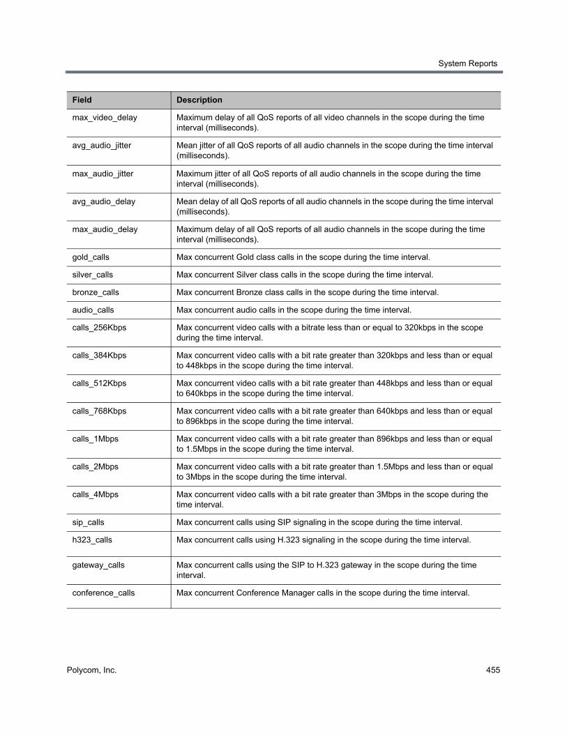
System Reports
Polycom, Inc. 455
max_video_delay Maximum delay of all QoS reports of all video channels in the scope during the time interval (milliseconds).
avg_audio_jitter Mean jitter of all QoS reports of all audio channels in the scope during the time interval (milliseconds).
max_audio_jitter Maximum jitter of all QoS reports of all audio channels in the scope during the time interval (milliseconds).
avg_audio_delay Mean delay of all QoS reports of all audio channels in the scope during the time interval (milliseconds).
max_audio_delay Maximum delay of all QoS reports of all audio channels in the scope during the time interval (milliseconds).
gold_calls Max concurrent Gold class calls in the scope during the time interval.
silver_calls Max concurrent Silver class calls in the scope during the time interval.
bronze_calls Max concurrent Bronze class calls in the scope during the time interval.
audio_calls Max concurrent audio calls in the scope during the time interval.
calls_256Kbps Max concurrent video calls with a bitrate less than or equal to 320kbps in the scope during the time interval.
calls_384Kbps Max concurrent video calls with a bit rate greater than 320kbps and less than or equal to 448kbps in the scope during the time interval.
calls_512Kbps Max concurrent video calls with a bit rate greater than 448kbps and less than or equal to 640kbps in the scope during the time interval.
calls_768Kbps Max concurrent video calls with a bit rate greater than 640kbps and less than or equal to 896kbps in the scope during the time interval.
calls_1Mbps Max concurrent video calls with a bit rate greater than 896kbps and less than or equal to 1.5Mbps in the scope during the time interval.
calls_2Mbps Max concurrent video calls with a bit rate greater than 1.5Mbps and less than or equal to 3Mbps in the scope during the time interval.
calls_4Mbps Max concurrent video calls with a bit rate greater than 3Mbps in the scope during the time interval.
sip_calls Max concurrent calls using SIP signaling in the scope during the time interval.
h323_calls Max concurrent calls using H.323 signaling in the scope during the time interval.
gateway_calls Max concurrent calls using the SIP to H.323 gateway in the scope during the time interval.
conference_calls Max concurrent Conference Manager calls in the scope during the time interval.
Field Description
System Reports
Polycom, Inc. 456
To download network usage data
1 Go to Reports > Network Usage.
2 In the Actions list, click Export Network Usage Data.
3 In the Export Time Frame dialog, set the Start Date and time and the End Date and time you want to include.
The defaults provide all network usage data for the current day.
4 Click OK.
5 Choose a path and filename for the network usage file and click Save.
The File Download dialog shows the progress.
6 When the download is complete, click Close.
You can open the CSV file with Microsoft Excel or another spreadsheet application. The file contains a line for each data point.
See also:
System Reports
Call History
About Site Topology
Polycom, Inc. 457
Polycom RealPresence DMA System SNMP Support
This section provides a discussion of the Polycom® RealPresence® Distributed Media Application™ (DMA®) SNMP support. It includes these topics:
● SNMP Overview
● Configure SNMP
● Download MIBs
SNMP OverviewSNMP is an application-layer protocol that provides a message format for communication between SNMP managers and agents. SNMP provides a standardized framework and a common language used for the monitoring and management of resources in a network.
Support for SNMP and system logging are part of Polycom’s management instrumentation solution. For detailed information on using the manageability instrumentation solution with your Polycom products, see the Polycom RealPresence Manageability Instrumentation Solution Guide.
This section includes the following topics:
● SNMP Framework
● SNMP Notifications
● SNMP Versions
SNMP FrameworkThe SNMP framework has three parts:
● An SNMP manager
The SNMP manager is the system used to control and monitor the activities of network hosts using SNMP. A variety of network management applications are available for use with SNMP. It is important to note that you should understand how your SNMP management system is configured to properly configure your Polycom system SNMP transport protocol requirements, SNMP version requirements, SNMP authentication requirements, and SNMP privacy requirements. For information on using SNMP management systems, see the appropriate documentation for your application.
● An SNMP agent
The SNMP agent is the software component within the Polycom system that maintains the data for the system and reports these data, as needed, to managing systems. The agent and MIB reside on the same system.
Polycom RealPresence DMA System SNMP Support
Polycom, Inc. 458
● A MIB
The MIB (Management Information Base) is a virtual information storage area for network management information, which consists of collections of managed network objects. You can configure the SNMP agent for a particular system MIB. The agent gathers data from the MIB, the repository for information about system parameters and network data. Polycom systems include Polycom-specific MIBs with every system as well as third-party MIBs. Polycom MIBs are self-documenting, including information about the purpose of specific traps and inform notifications. Third-party MIBs accessible through the Polycom system may include both hardware and software system MIBs.
SNMP NotificationsA key feature of SNMP is the ability to generate notifications from an SNMP agent. Notifications are called as such because they are sent, unsolicited and asynchronous to the SNMP manager from the Polycom system. Notifications can indicate improper user authentication, restarts, the closing of a connection, loss of connection to another system, or other significant events. They are generated as informs or trap requests.
Traps are messages alerting the SNMP manager to a system or network condition change. Inform requests (informs) are traps that include a request for a confirmation receipt from the SNMP manager. Traps are less reliable than informs because the SNMP manager does not send any acknowledgment when it receives a trap. However, informs consume more system and network resources. Traps are discarded as soon as they are sent. An inform request is held in memory until a response is received or the request times out. Traps are sent only once while informs may be retried several times.The retries increase traffic and contribute to a higher overhead on the network. Thus, traps and inform requests provide a trade-off between reliability and network resources.
SNMP VersionsPolycom supports two versions of SNMP:
● SNMPv2c—Polycom implements a sub-version of SNMPv2. SNMPv2c uses a community-based form of security. The community of SNMP managers able to access the agent MIB is defined by an IP-based Access Control List and password.
One drawback of SNMPv2c is that it is subject to packet sniffing of the clear text community string from the network traffic, because it does not encrypt communications between the management system and SNMP agents.
● SNMPv3—Polycom implements the newest version of SNMP. Its primary feature is enhanced security. SNMPv3 provides secure access to systems with a combination of authenticating and encrypting packets over the network.The contextEngineID in SNMPv3 uniquely identifies each SNMP entity. The contextEngineID is used to generate the key for authenticated messages. Polycom implements SNMPv3 communication with authentication and privacy (the authPriv security level as defined in the USM MIB).
Authentication is used to ensure that traps are read by only the intended recipient. As messages are created, they are given a special key that is based on the contextEngineID of the entity. The key is shared with the intended recipient and used to receive the message.
Privacy encrypts the SNMP message to ensure that it cannot be read by unauthorized users.
Message integrity ensures that a packet has not been tampered with in transit.
Polycom RealPresence DMA System SNMP Support
Polycom, Inc. 459
Configure SNMPThe RealPresence DMA system uses SNMP to provide a standardized framework and a common language used monitoring and managing the system.
Note that you should understand how your SNMP management system is configured to properly configure the RealPresence DMA system’s SNMP transport protocol, version, authentication, and privacy settings.
To enable SNMP messaging you must perform the following:
● Enable the SNMP Agent
● Add an SNMP Notification User
● Add an SNMP Notification Agent
Enable the SNMP AgentYou can enable the SNMP Agent.
To enable the SNMP agent
1 Go to Admin > Local Cluster > SNMP Settings.
2 Configure the following settings for the connection between the RealPresence DMA system and the SNMP agent.
Setting Description
SNMP Version Specifies the version of SNMP you want to use.
v2c–Used for standard models. Uses community-based authentication.
v3–Used when you want a high security model. Requires a security user for notifications.
Transport Specifies the transport protocol for SNMP communications. SNMP can be implemented over two transport protocols:
TCP–This protocol has error-recovery services, message delivery is assured, and messages are delivered in the order they were sent. Some SNMP managers only support SNMP over TCP.
UDP–This protocol does not provide error-recovery services, message delivery is not assured, and messages are not necessarily delivered in the order they were sent.
Because UDP doesn't have error recovery services, it requires fewer network resources. It is well suited for repetitive, low-priority functions like alarm monitoring.
Port Specifies the port that the RealPresence DMA system uses for general SNMP messages. By default, the RealPresence DMA system uses port 161.
Community For SNMPv2c, specifies the context for the information, which is the SNMP group to which the devices and management stations running SNMP belong.
The RealPresence DMA system has only one valid context—by default, public—which is identified by this Community name. The RealPresence DMA system will not respond to requests from management systems that do not belong to its community.
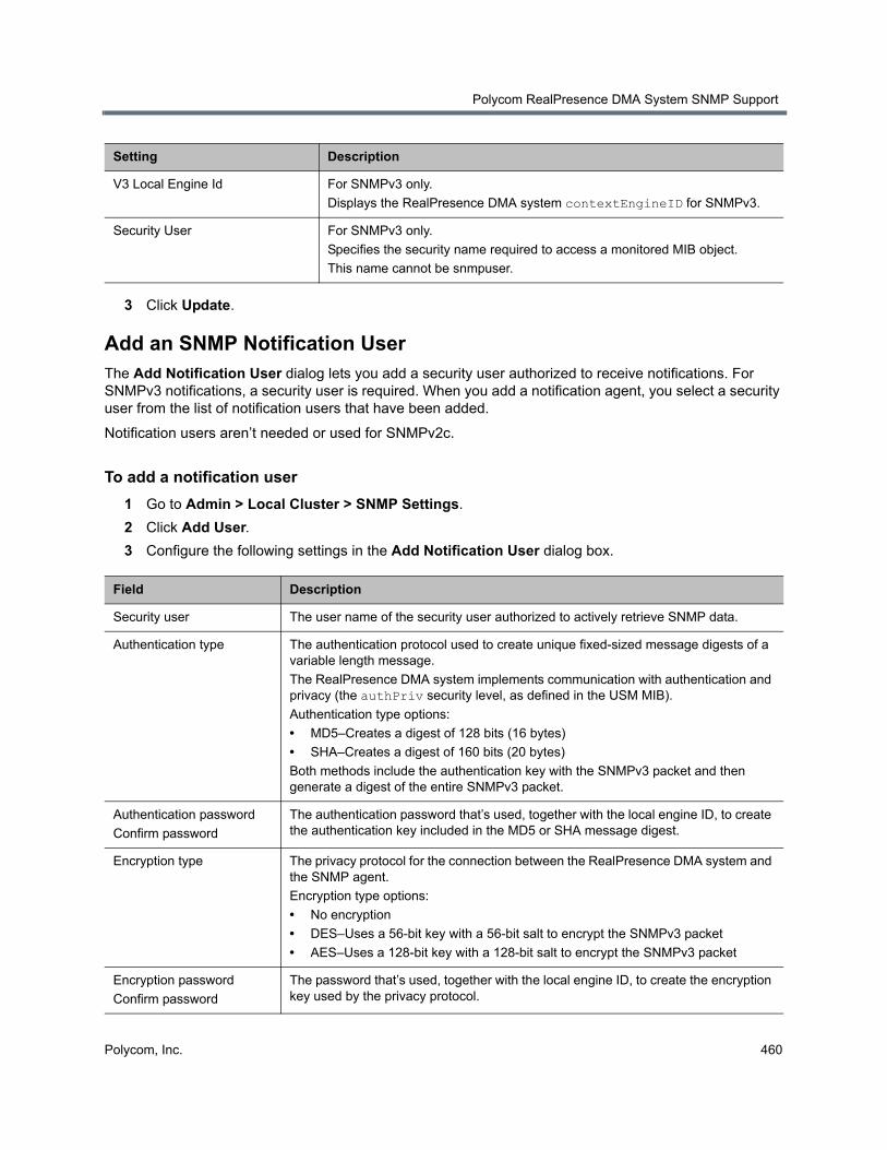
Polycom RealPresence DMA System SNMP Support
Polycom, Inc. 460
3 Click Update.
Add an SNMP Notification UserThe Add Notification User dialog lets you add a security user authorized to receive notifications. For SNMPv3 notifications, a security user is required. When you add a notification agent, you select a security user from the list of notification users that have been added.
Notification users aren’t needed or used for SNMPv2c.
To add a notification user
1 Go to Admin > Local Cluster > SNMP Settings.
2 Click Add User.
3 Configure the following settings in the Add Notification User dialog box.
V3 Local Engine Id For SNMPv3 only.
Displays the RealPresence DMA system contextEngineID for SNMPv3.
Security User For SNMPv3 only.
Specifies the security name required to access a monitored MIB object.
This name cannot be snmpuser.
Field Description
Security user The user name of the security user authorized to actively retrieve SNMP data.
Authentication type The authentication protocol used to create unique fixed-sized message digests of a variable length message.
The RealPresence DMA system implements communication with authentication and privacy (the authPriv security level, as defined in the USM MIB).
Authentication type options:
• MD5–Creates a digest of 128 bits (16 bytes)
• SHA–Creates a digest of 160 bits (20 bytes)
Both methods include the authentication key with the SNMPv3 packet and then generate a digest of the entire SNMPv3 packet.
Authentication password
Confirm password
The authentication password that’s used, together with the local engine ID, to create the authentication key included in the MD5 or SHA message digest.
Encryption type The privacy protocol for the connection between the RealPresence DMA system and the SNMP agent.
Encryption type options:
• No encryption
• DES–Uses a 56-bit key with a 56-bit salt to encrypt the SNMPv3 packet
• AES–Uses a 128-bit key with a 128-bit salt to encrypt the SNMPv3 packet
Encryption password
Confirm password
The password that’s used, together with the local engine ID, to create the encryption key used by the privacy protocol.
Setting Description
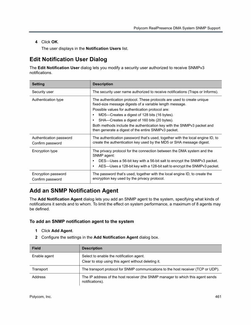
Polycom RealPresence DMA System SNMP Support
Polycom, Inc. 461
4 Click OK.
The user displays in the Notification Users list.
Edit Notification User DialogThe Edit Notification User dialog lets you modify a security user authorized to receive SNMPv3 notifications.
Add an SNMP Notification AgentThe Add Notification Agent dialog lets you add an SNMP agent to the system, specifying what kinds of notifications it sends and to whom. To limit the effect on system performance, a maximum of 8 agents may be defined.
To add an SNMP notification agent to the system
1 Click Add Agent.
2 Configure the settings in the Add Notification Agent dialog box.
Setting Description
Security user The security user name authorized to receive notifications (Traps or Informs).
Authentication type The authentication protocol. These protocols are used to create unique fixed-size message digests of a variable length message.
Possible values for authentication protocol are:
• MD5—Creates a digest of 128 bits (16 bytes).
• SHA—Creates a digest of 160 bits (20 bytes).
Both methods include the authentication key with the SNMPv3 packet and then generate a digest of the entire SNMPv3 packet.
Authentication password
Confirm password
The authentication password that’s used, together with the local engine ID, to create the authentication key used by the MD5 or SHA message digest.
Encryption type The privacy protocol for the connection between the DMA system and the SNMP agent:
• DES—Uses a 56-bit key with a 56-bit salt to encrypt the SNMPv3 packet.
• AES—Uses a 128-bit key with a 128-bit salt to encrypt the SNMPv3 packet.
Encryption password
Confirm password
The password that’s used, together with the local engine ID, to create the encryption key used by the privacy protocol.
Field Description
Enable agent Select to enable the notification agent.
Clear to stop using this agent without deleting it.
Transport The transport protocol for SNMP communications to the host receiver (TCP or UDP).
Address The IP address of the host receiver (the SNMP manager to which this agent sends notifications).
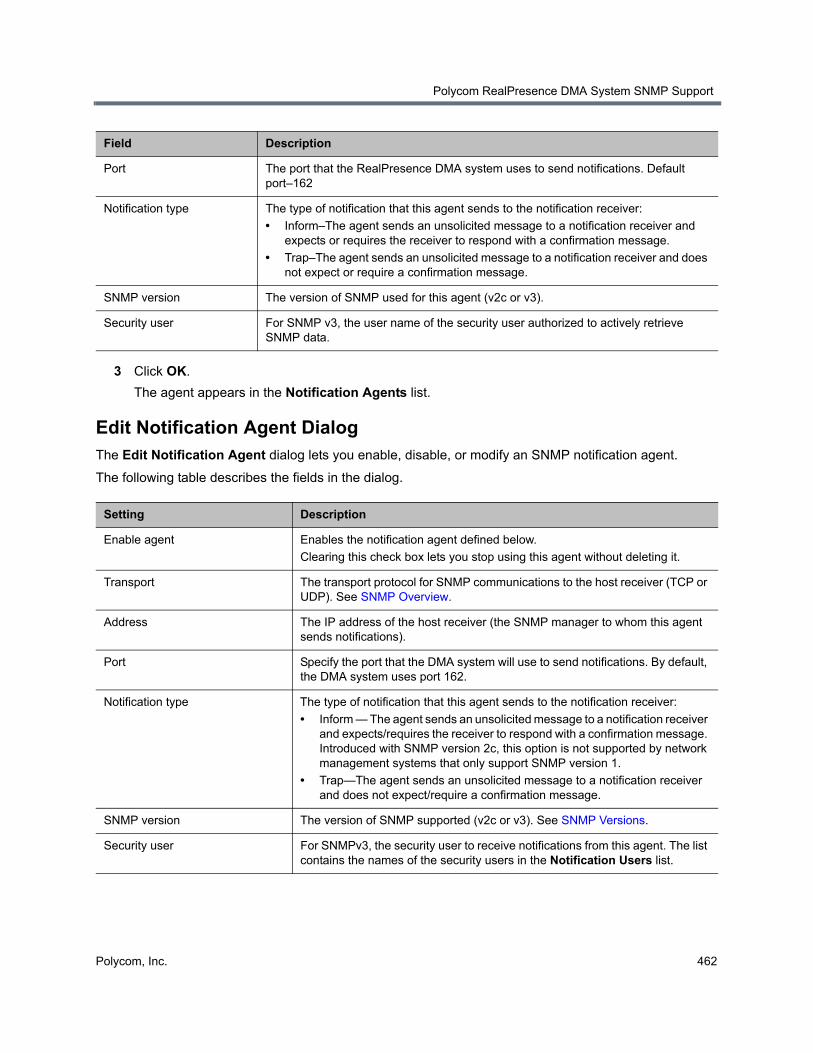
Polycom RealPresence DMA System SNMP Support
Polycom, Inc. 462
3 Click OK.
The agent appears in the Notification Agents list.
Edit Notification Agent DialogThe Edit Notification Agent dialog lets you enable, disable, or modify an SNMP notification agent.
The following table describes the fields in the dialog.
Port The port that the RealPresence DMA system uses to send notifications. Default port–162
Notification type The type of notification that this agent sends to the notification receiver:
• Inform–The agent sends an unsolicited message to a notification receiver and expects or requires the receiver to respond with a confirmation message.
• Trap–The agent sends an unsolicited message to a notification receiver and does not expect or require a confirmation message.
SNMP version The version of SNMP used for this agent (v2c or v3).
Security user For SNMP v3, the user name of the security user authorized to actively retrieve SNMP data.
Setting Description
Enable agent Enables the notification agent defined below.
Clearing this check box lets you stop using this agent without deleting it.
Transport The transport protocol for SNMP communications to the host receiver (TCP or UDP). See SNMP Overview.
Address The IP address of the host receiver (the SNMP manager to whom this agent sends notifications).
Port Specify the port that the DMA system will use to send notifications. By default, the DMA system uses port 162.
Notification type The type of notification that this agent sends to the notification receiver:
• Inform — The agent sends an unsolicited message to a notification receiver and expects/requires the receiver to respond with a confirmation message. Introduced with SNMP version 2c, this option is not supported by network management systems that only support SNMP version 1.
• Trap—The agent sends an unsolicited message to a notification receiver and does not expect/require a confirmation message.
SNMP version The version of SNMP supported (v2c or v3). See SNMP Versions.
Security user For SNMPv3, the security user to receive notifications from this agent. The list contains the names of the security users in the Notification Users list.
Field Description
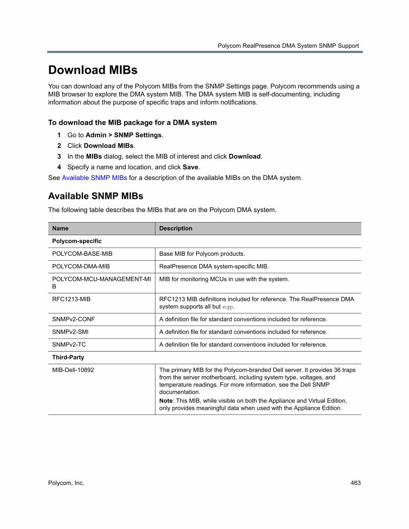
Polycom RealPresence DMA System SNMP Support
Polycom, Inc. 463
Download MIBsYou can download any of the Polycom MIBs from the SNMP Settings page. Polycom recommends using a MIB browser to explore the DMA system MIB. The DMA system MIB is self-documenting, including information about the purpose of specific traps and inform notifications.
To download the MIB package for a DMA system
1 Go to Admin > SNMP Settings.
2 Click Download MIBs.
3 In the MIBs dialog, select the MIB of interest and click Download.
4 Specify a name and location, and click Save.
See Available SNMP MIBs for a description of the available MIBs on the DMA system.
Available SNMP MIBsThe following table describes the MIBs that are on the Polycom DMA system.
Name Description
Polycom-specific
POLYCOM-BASE-MIB Base MIB for Polycom products.
POLYCOM-DMA-MIB RealPresence DMA system-specific MIB.
POLYCOM-MCU-MANAGEMENT-MIB
MIB for monitoring MCUs in use with the system.
RFC1213-MIB RFC1213 MIB definitions included for reference. The RealPresence DMA system supports all but egp.
SNMPv2-CONF A definition file for standard conventions included for reference.
SNMPv2-SMI A definition file for standard conventions included for reference.
SNMPv2-TC A definition file for standard conventions included for reference.
Third-Party
MIB-Dell-10892 The primary MIB for the Polycom-branded Dell server. It provides 36 traps from the server motherboard, including system type, voltages, and temperature readings. For more information, see the Dell SNMP documentation.
Note: This MIB, while visible on both the Appliance and Virtual Edition, only provides meaningful data when used with the Appliance Edition.