police in-car camera and mdvr system quick … 210 install ver 1.0.pdfpolice in-car camera and mdvr...
TRANSCRIPT
Quick Installation Guide April 2008
1
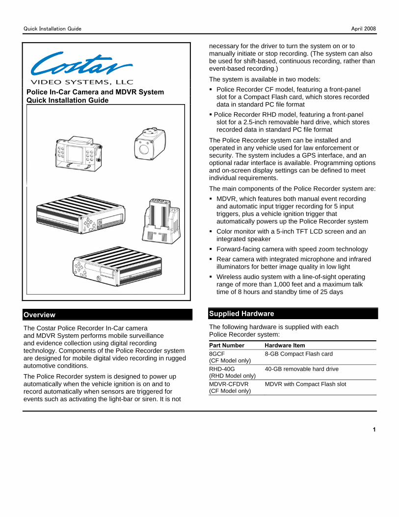
Police In-Car Camera and MDVR System Quick Installation Guide
Overview
The Costar Police Recorder In-Car cameraand MDVR System performs mobile surveillance and evidence collection using digital recording technology. Components of the Police Recorder system are designed for mobile digital video recording in rugged automotive conditions. The Police Recorder system is designed to power up automatically when the vehicle ignition is on and to record automatically when sensors are triggered for events such as activating the light-bar or siren. It is not
necessary for the driver to turn the system on or to manually initiate or stop recording. (The system can also be used for shift-based, continuous recording, rather than event-based recording.) The system is available in two models: Police Recorder CF model, featuring a front-panel
slot for a Compact Flash card, which stores recorded data in standard PC file format
Police Recorder RHD model, featuring a front-panel slot for a 2.5-inch removable hard drive, which stores recorded data in standard PC file format
The Police Recorder system can be installed and operated in any vehicle used for law enforcement or security. The system includes a GPS interface, and an optional radar interface is available. Programming options and on-screen display settings can be defined to meet individual requirements. The main components of the Police Recorder system are: MDVR, which features both manual event recording
and automatic input trigger recording for 5 input triggers, plus a vehicle ignition trigger that automatically powers up the Police Recorder system
Color monitor with a 5-inch TFT LCD screen and an integrated speaker
Forward-facing camera with speed zoom technology Rear camera with integrated microphone and infrared
illuminators for better image quality in low light Wireless audio system with a line-of-sight operating
range of more than 1,000 feet and a maximum talk time of 8 hours and standby time of 25 days
Supplied Hardware
The following hardware is supplied with each Police Recorder system:
Part Number Hardware Item 8GCF (CF Model only)
8-GB Compact Flash card
RHD-40G (RHD Model only)
40-GB removable hard drive
MDVR-CFDVR (CF Model only)
MDVR with Compact Flash slot
Quick Installation Guide April 2008
2
Part Number Hardware Item MDVR-HD (RHD Model only)
MDVR with removable hard drive
MDVR-UMOUNT Universal visor bracket for forward-facing camera
MDVR-POLICE-CB MDVR main wiring harness MDVR-AUDIO-CB Wireless audio system interface cable SI-C558IR Rear camera MDVR-CAM-CB Rear camera cableMDVR-SLCD .....5-inch color monitor
O Wireless audio system charging
System Components Components of the Police Recorder system afollows:
MDVR
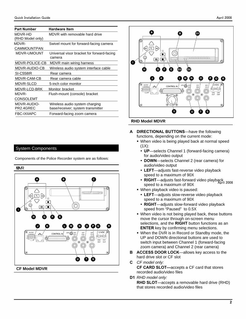
CF Model MDVR
RHD Model MDVR
A DIRECTIONAL BUTTONS—have the following functions, depending on the current mode: When video is being played back at normal speed (1X): UP—selects Channel 1 (forward-facing camera) for audio/video output
DOWN—selects Channel 2 (rear camera) for audio/video output
LEFT—adjusts fast-reverse video playback speed to a maximum of 90X
RIGHT—adjusts fast-forward video playback speed to a maximum of 90X
When playback video is paused: LEFT—adjusts slow-reverse video playback speed to a maximum of 90X
RIGHT—adjusts slow-forward video playback speed from “Paused” to 0.5X
When video is not being played back, these buttons move the cursor through on-screen menu selections, and the RIGHT button functions as an ENTER key by confirming menu selections.
When the DVR is in Record or Standby mode, the UP and DOWN directional buttons are used to switch input between Channel 1 (forward-facing zoom camera) and Channel 2 (rear camera)
B ACCESS DOOR LOCK—allows key access to the hard drive slot or CF slot
C CF model only: CF CARD SLOT—accepts a CF card that stores recorded audio/video files
D1 RHD model only: RHD SLOT—accepts a removable hard drive (RHD) that stores recorded audio/video files
MDVR-LCD-BRK......Monitor-bracket MDVR- ......Flush-mount-(console)-bracket CONSOLEMT
MDVR-AUDIO- Wireless audio system charging PR2.4GREC base/receiver; system transmitter
FBC-IXIIAPC Forward-facing zoom camera
em Components
MDVR- Swivel mount for forward-facing cameraCAMMOUNTPAN
System Components
MDVR
April 2008
RHD Model MDVR
CF Model MDVR
Components of the Police Recorder system are as follows:
Quick Installation Guide April 2008
3
D2 RHD model only: DATA/POWER LEDs—yellow LED (on the left) lights when data is being written to the removable hard drive; green LED (on the right) lights when the removable hard drive is powered on.
D3 RHD model only: EJECT BUTTON—ejects the removable hard drive
E RECORD BUTTON—starts manual recording F STOP BUTTON—stops playback video and resumes
the live view
CAUTION: To prevent corruption of the hard drive, press the STOP button BEFORE removing the hard drive.
G PAUSE BUTTON—pauses playback video (or resumes paused video playback)
H POWER BUTTON—has the following functions: When pressed and released, manually powers the MDVR ON or OFF
NOTE: In typical installations, the MDVR is powered ON and OFF automatically by the vehicle-ignition sensor. When it has been powered ON manually, the MDVR remains ON until the POWER button is pressed again. When the MDVR is already ON because it has been triggered by a sensor, pressing the POWER button powers the MDVR OFF, but the MDVR immediately powers ON again to continue the programmed recording.
When pressed and held for 10 seconds, resets the MDVR, which restores the original manufacturer default settings. (Resetting the MDVR does not affect files stored on the removable hard drive.)
I SEARCH/MENU BUTTON—when pressed and released, initiates display of the Search menu for audio/video files stored on the CF card or hard drive; when pressed and held for 3 seconds, initiates display of the Main menu
J AUDIO CONTROL RECEPTACLE—accepts the connector of the wireless audio system interface cable (Part Number MDVR-AUDIO-CB)
K ETHERNET PORT—accepts the RJ45 connector of an optional Ethernet cable; can be used to download files through a wired or wireless Ethernet connection
L CONTROL IN RECEPTACLE—accepts the 25-pin DSUB connector of the main wiring harness (Part Number MDVR-POLICE-CB)
M GPS RECEPTACLE—accepts the connector for the GPS module
N VIDEO OUTPUT—accepts the yellow video connector of the audio-video adapter cable 4PIN/RCA
O A/V CH2—accepts the yellow video connector of the rear camera cable (Part Number MDVR-CAM-CB)
P A/V CH1—accepts the yellow video connector of the forward-facing zoom camera cable
Q 12 VDC, CH2 OUT— accepts the Molex connector of the rear camera cable (Part Number MDVR-CAM-CB) and supplies 12 VDC power to the rear camera (Part Number SI-C558IR)
R 12 VDC, CH1 OUT—not used in typical Police Recorder system installations
S A/V OUT—not used in typical Police Recorder system installations
T A/V CH2—accepts the white audio connector of the rear camera cable (Part Number MDVR-CAM-CB)
U AUDIO OUTPUT—accepts the white audio connector audio-video adapter cable 4PIN/RCA
V RHD model only: FAN—cools the MDVR by maintaining air flow
Monitor with Integrated Speaker Part Number MDVR-5LCD
Quick Installation Guide April 2008
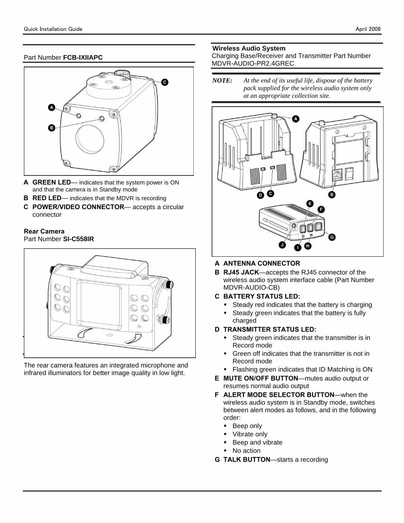
Part Number FCB-IXIIAPC
A GREEN LED— indicates that the system power is ON
and that the camera is in Standby mode B RED LED— indicates that the MDVR is recording C POWER/VIDEO CONNECTOR— accepts a circular
connector
Rear Camera Part Number SI-C558IR
The rear camera features an integrated microphone and infrared illuminators for better image quality in low light.
Wireless Audio System
Charging Base/Receiver and Transmitter Part Number MDVR-AUDIO-PR2.4GREC
NOTE: At the end of its useful life, dispose of the battery pack supplied for the wireless audio system only at an appropriate collection site.
A ANTENNA CONNECTOR B RJ45 JACK—accepts the RJ45 connector of the
wireless audio system interface cable (Part Number MDVR-AUDIO-CB)
C BATTERY STATUS LED: Steady red indicates that the battery is charging Steady green indicates that the battery is fully
charged D TRANSMITTER STATUS LED:
Steady green indicates that the transmitter is in Record mode
Green off indicates that the transmitter is not in Record mode
Flashing green indicates that ID Matching is ON E MUTE ON/OFF BUTTON—mutes audio output or
resumes normal audio output F ALERT MODE SELECTOR BUTTON—when the
wireless audio system is in Standby mode, switches between alert modes as follows, and in the following order: Beep only Vibrate only Beep and vibrate No action
G TALK BUTTON—starts a recording
Wireless Audio System
Quick Installation Guide April 2008
5
H GREEN STATUS LED: Steady green indicates that the transmitter is ON
and in Standby mode Flashing green indicates that audio output is
muted I RED BATTERY STATUS LED:
Steady red indicates a low battery Flashing red indicates that the transmitter is out of
range of the base J MICROPHONE JACK—for optional lapel microphone
Important Installation Precautions
Keep the following precautions in mind when installing the Police Recorder system: IMPORTANT: To reduce the risk of electrical shock,
disconnect the vehicle negative battery terminal during Police Recorder system installation.
To prevent system damage, the main wiring harness (Part Number MDVR-POLICE-CB) must not be connected to the vehicle electrical system until all other components and cables are installed and connected.
The ground wire of the main wiring harness (Part Number MDVR-POLICE-CB) must be connected directly to the vehicle chassis.
Use care when affixing any device to a vehicle with screws. Before drilling or inserting screws, ensure that vehicle components such as the gas tank and airbags will not be damaged by the drill bit or screw.
To prevent system damage, use only the cables supplied with the Police Recorder system.
Do not disassemble any component of the Police Recorder system.
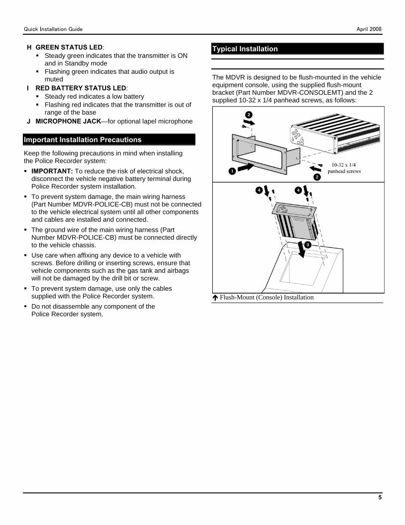
Typical Installation
The MDVR is designed to be flush-mounted in the vehicle equipment console, using the supplied flush-mount bracket (Part Number MDVR-CONSOLEMT) and the 2 supplied 10-32 x 1/4 panhead screws, as follows:
Flush-Mount (Console) Installation
Quick Installation Guide April 2008
6
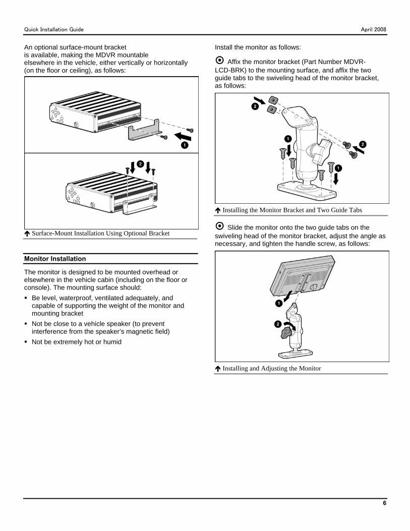
An optional surface-mount bracket is available, making the MDVR mountable elsewhere in the vehicle, either vertically or horizontally (on the floor or ceiling), as follows:
Surface-Mount Installation Using Optional Bracket
Monitor Installation
The monitor is designed to be mounted overhead or elsewhere in the vehicle cabin (including on the floor or console). The mounting surface should: Be level, waterproof, ventilated adequately, and
capable of supporting the weight of the monitor and mounting bracket
Not be close to a vehicle speaker (to prevent interference from the speaker’s magnetic field)
Not be extremely hot or humid
Install the monitor as follows:
Affix the monitor bracket (Part Number MDVR-LCD-BRK) to the mounting surface, and affix the two guide tabs to the swiveling head of the monitor bracket, as follows:
Installing the Monitor Bracket and Two Guide Tabs
Slide the monitor onto the two guide tabs on the swiveling head of the monitor bracket, adjust the angle as necessary, and tighten the handle screw, as follows:
Installing and Adjusting the Monitor
Quick Installation Guide April 2008
7
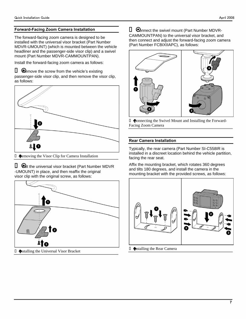
Forward-Facing Zoom Camera Installation
The forward-facing zoom camera is designed to be installed with the universal visor bracket (Part Number MDVR-UMOUNT) (which is mounted between the vehicle headliner and the passenger-side visor clip) and a swivel mount (Part Number MDVR-CAMMOUNTPAN). Install the forward-facing zoom camera as follows:
Remove the screw from the vehicle’s existing passenger-side visor clip, and then remove the visor clip, as follows:
Removing the Visor Clip for Camera Installation
Put the universal visor bracket (Part Number MDVR-UMOUNT) in place, and then reaffix the original visor clip with the original screw, as follows:
Installing the Universal Visor Bracket
Connect the swivel mount (Part Number MDVR- CAMMOUNTPAN) to the universal visor bracket, and then connect and adjust the forward-facing zoom camera (Part Number FCBIXIIAPC), as follows:
Connecting the Swivel Mount and Installing the Forward-
Facing Zoom Camera
Rear Camera Installation
Typically, the rear camera (Part Number SI-C558IR is installed in a discreet location behind the vehicle partition, facing the rear seat. Affix the mounting bracket, which rotates 360 degrees and tilts 180 degrees, and install the camera in the mounting bracket with the provided screws, as follows:
Installing the Rear Camera
Quick Installation Guide April 2008
8
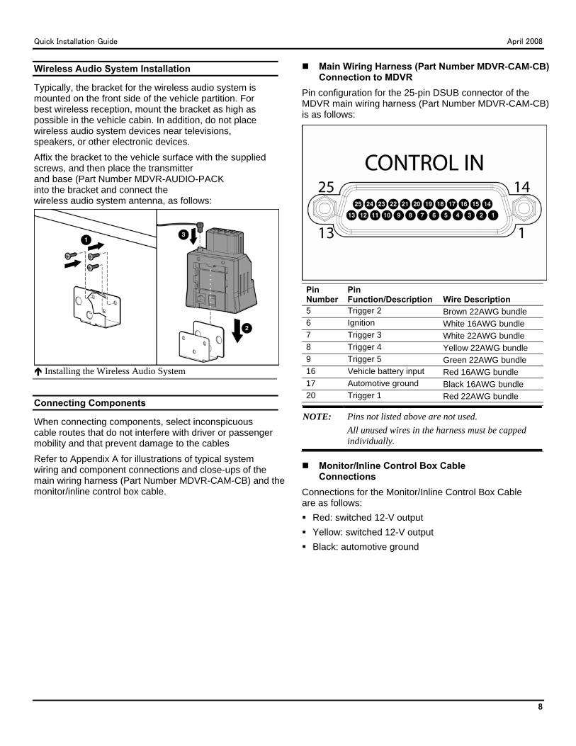
Wireless Audio System Installation
Typically, the bracket for the wireless audio system is mounted on the front side of the vehicle partition. For best wireless reception, mount the bracket as high as possible in the vehicle cabin. In addition, do not place wireless audio system devices near televisions, speakers, or other electronic devices. Affix the bracket to the vehicle surface with the supplied screws, and then place the transmitter and base (Part Number MDVR-AUDIO-PACKinto the bracket and connect the wireless audio system antenna, as follows:
Installing the Wireless Audio System
Connecting Components
When connecting components, select inconspicuous cable routes that do not interfere with driver or passenger mobility and that prevent damage to the cables Refer to Appendix A for illustrations of typical system wiring and component connections and close-ups of the main wiring harness (Part Number MDVR-CAM-CB) and the monitor/inline control box cable.
Main Wiring Harness (Part Number MDVR-CAM-CB) Connection to MDVR
Pin configuration for the 25-pin DSUB connector of the MDVR main wiring harness (Part Number MDVR-CAM-CB) is as follows:
Pin Number
Pin Function/Description Wire Description
5 Trigger 2 Brown 22AWG bundle 6 Ignition White 16AWG bundle 7 Trigger 3 White 22AWG bundle 8 Trigger 4 Yellow 22AWG bundle 9 Trigger 5 Green 22AWG bundle 16 Vehicle battery input Red 16AWG bundle 17 Automotive ground Black 16AWG bundle 20 Trigger 1 Red 22AWG bundle
NOTE: Pins not listed above are not used. All unused wires in the harness must be capped individually.
Monitor/Inline Control Box Cable Connections
Connections for the Monitor/Inline Control Box Cable are as follows: Red: switched 12-V output Yellow: switched 12-V output Black: automotive ground
Quick Installation Guide April 2008
9
Initial Setup
To initiate display of the Main menu, press and hold the SEARCH/MENU button on the front panel of the
MDVR for 3 seconds. Use the DIRECTIONAL buttons to move the cursor through on-screen menu selections. When you have finished setting up a menu item, press the SEARCH/MENU button again to save the changes.
NOTE: After several seconds of inactivity, the menu is no longer displayed, and the SEARCH/MENU button must be pressed again to initiate display of the main menu again.
Main Menu
The main menu includes the following menus: Setup Titles Trigger Setup Record Setup GPS Setup System Info
For detailed information about these menus, refer to Appendix B.
Default Menu Settings
Default settings, which are valid for most typical Police Recorder system installations, are as follows: Setup Menu
Video In Select: MANUAL Video In Dwell: N/A Units: ENGLISH Audio Volume: 12 dB, 6 dB Time Setup: Default value for Daylight Saving Time
is ON Password Setup: Default value for Password is
LEFT, RIGHT, LEFT, RIGHT, LEFT, RIGHT; default value for the password requirement is DISABLED for all 4 levels of operation.
Titles Menu System Name: SV Trigger 1: L Triggers 2 through 5: 2 through 5, respectively Trigger 6: M
Trigger Setup Menu 1: RECORD, ACTIVE HIGH 2: DISPLAY ONLY, ACTIVE HIGH 3: DISPLAY ONLY, ACTIVE HIGH 4: DISPLAY ONLY, ACTIVE HIGH 5: DISPLAY ONLY, ACTIVE HIGH 6: RECORD, ACTIVE LOW
Record Setup Menu Record Mode: STOP IF FULL Audio Recording: ON Image Size: 320x240 Image Quality: MEDIUM Frame Rate: 30
Advanced Record Setup Menu Pre-Event Time: 60 secs Max File Time: 10 mins Pre-Event Audio: OFF Priority Prompt: OFF
GPS Menu Use GPS: YES Use GPS Time: YES UTC/Local Time: -6 GPS Data Format: DDD:HH:SS
Camera Setup Menu Camera Protocol: VISCA One Touch Zoom: 75% Focus: AUTO Sensitivity: HIGH Slow Shutter: OFF
Quick Installation Guide April 2008
10
Basic Operation
The Police Recorder system is designed to power up automatically when the vehicle ignition is on and to record automatically when sensors are triggered for events such as activating the light-bar or siren. (The system can also be used for shift-based, continuous recording, rather than event-based recording.) When the system is used for event-based recording, it is not necessary for the driver to turn the system on or to manually initiate or stop recording. However, an officer can start a recording manually and can control the system as follows:
Starting a Manual MDVR Recording
To start a recording manually, press the RECORD button on the front panel of the MDVR, or press the TALK button on the wireless audio system transmitter.
Switching Audio/Video Input
When the DVR is in Record or Standby mode, use the UP and DOWN directional buttons on the front panel of the MDVR to switch input between Channel 1 (forward-facing zoom camera) and Channel 2 (rear camera).
Automatic Audio Input
When the DVR is in Record mode, audio input from the integrated microphone of the cabin camera is activated automatically. When the DVR is in Record mode and the wireless audio transmitter is removed from the charging base/receiver, audio input from the wireless audio transmitter is activated automatically.
MDVR Recording Capacity
The recording capacity of the MDVR depends on the following user-selectable factors: Frame rate (30 fps to 1/8 fps [for time-lapse recording]) Image quality (high, medium high, medium, medium
low, or low) Image resolution (640 or 320 x 240 pixels) Storage capacity of the archive media type (CF card or
removable hard drive)
Activating the Speed Zoom Function of the Forward-Facing Camera
To activate the forward-facing camera’s speed zoom function, press the RIGHT directional button on the MDVR front panel. When activated, the forward-facing camera’s speed zoom function causes the camera to zoom in to a pre-set magnification (7.5X default) and remain magnified for 4 seconds before returning to the wide (normal) field of view.
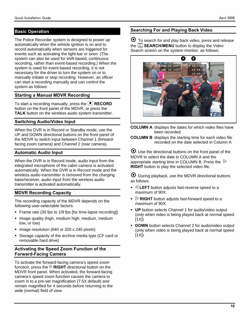
Searching For and Playing Back Video
To search for and play back video, press and release the SEARCH/MENU button to display the Video Search screen on the system monitor, as follows:
COLUMN A displays the dates for which video files have
been recorded COLUMN B displays the starting time for each video file
recorded on the date selected in Column A
Use the directional buttons on the front panel of the MDVR to select the date in COLUMN A and the appropriate starting time in COLUMN B. Press the RIGHT button to play the selected video file.
During playback, use the MDVR directional buttons as follows: LEFT button adjusts fast-reverse speed to a
maximum of 90X. RIGHT button adjusts fast-forward speed to a
maximum of 90X. UP button selects Channel 1 for audio/video output
(only when video is being played back at normal speed [1X])
DOWN button selects Channel 2 for audio/video output (only when video is being played back at normal speed [1X])
Quick Installation Guide April 2008
11
Archiving Video to a PC
WARNING: RHD Model Only: To prevent hard drive damage and loss of data stored on the removable hard drive, DO NOT use the Microsoft Windows operating system of the PC to format the removable hard drive. Use of the Windows operating system FORMAT command on the removable hard drive will erase all data stored on the removable hard drive and make the removable hard drive unusable in the MDVR. Furthermore, on some PCs, the operating system may not automatically recognize the removable hard drive, in which case the operating system will prompt the user about whether the unrecognized drive should be formatted. If appropriate, click the NO button in response to the following prompt:
THE DISK IN DRIVE X IS NOT FORMATTED. DO YOU WANT TO FORMAT IT NOW?
Connect the storage media to the PC, as follows:
For the CF model, insert the CF card that contains recorded Police Recorder system files into the CF card slot of the PC. (For PCs that do not have a CF card slot, an optional CF-to-USB adapter is available.)
For the RHD model, first connect the optional hard drive reader to a USB port on the PC.Next, plug the AC adapter into the hard drive reader. Then, insert the removable hard drive that contains recorded Police Recorder system files into the hard drive reader, and turn on the key of the hard drive reader.
The storage media (the CF card or the removable hard drive) will be recognized by the Microsoft Windows Operating System of the PC and assigned a drive letter in Microsoft Windows Explorer, which can be used to copy video files from the storage media to the PC.
MDVR File Format
The MDVR stores recorded audio/video files on the installed archive media (CF card or removable hard drive) in standard PC file format. The MDVR saves each 10-minute segment in a separate file and automatically assigns a filename that identifies the source MDVR and the starting date and time of the segment. In addition, the filename identifies “continuation” files (files that are a continuation of another 10-minute segment) and “event” files (files that include a user-defined event such as activation of the vehicle backup lights). Following is an explanation of sample MDVR file names:
Explanation of Sample MDVR File Names
Removing the CF Card or Hard Drive from the MDVR
CAUTION: To prevent corruption of the CF card or hard drive, press the STOP button on the front panel of the MDVR panel BEFORE removing the CF card or hard drive.
Press the STOP button on the front panel of the MDVR.
Use one of the provided keys to unlock the access door lock on the front panel of the MDVR.
On the RHD model, press the EJECT button to eject the removable hard drive. On the CF model, simply pull the CF card out of the slot.
Meta-Data
The MDVR generates system information (meta-data) for each image frame and stores it on the archive media (either the CF card or the removable hard drive). The meta-data describes conditions (such as the date, time, and status of input triggers) present at the time of recording.
Quick Installation Guide April 2008
12
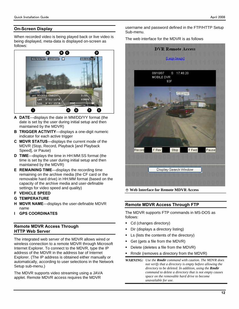
On-Screen Display
When recorded video is being played back or live video is being displayed, meta-data is displayed on-screen as follows:
A DATE—displays the date in MM/DD/YY format (the
date is set by the user during initial setup and then maintained by the MDVR)
B TRIGGER ACTIVITY—displays a one-digit numeric indicator for each active trigger
C MDVR STATUS—displays the current mode of the MDVR (Stop, Record, Playback [and Playback Speed], or Pause)
D TIME—displays the time in HH:MM:SS format (the time is set by the user during initial setup and then maintained by the MDVR)
E REMAINING TIME—displays the recording time remaining on the archive media (the CF card or the removable hard drive) in HH:MM format (based on the capacity of the archive media and user-definable settings for video speed and quality)
F VEHICLE SPEED G TEMPERATURE H MDVR NAME—displays the user-definable MDVR
name I GPS COORDINATES
Remote MDVR Access Through HTTP Web Server
The integrated web server of the MDVR allows wired or wireless connection to a remote MDVR through Microsoft Internet Explorer. To connect to the MDVR, type the IP address of the MDVR in the address bar of Internet Explorer. (The IP address is obtained either manually or automatically, according to user selections in the Network Setup sub-menu.)
The MDVR supports video streaming using a JAVA applet. Remote MDVR access requires the MDVR
username and password defined in the FTP/HTTP Setup Sub-menu.
The web interface for the MDVR is as follows
Web Interface for Remote MDVR Access
Remote MDVR Access Through FTP
The MDVR supports FTP commands in MS-DOS as follows: Cd (changes directory) Dir (displays a directory listing) Ls (lists the contents of the directory) Get (gets a file from the MDVR) Delete (deletes a file from the MDVR) Rmdir (removes a directory from the MDVR)
WARNING: Use the Rmdir command with caution. The MDVR does not verify that a directory is empty before allowing the directory to be deleted. In addition, using the Rmdir command to delete a directory that is not empty causes space on the removable hard drive to become unavailable for use.
Quick Installation Guide April 2008
13
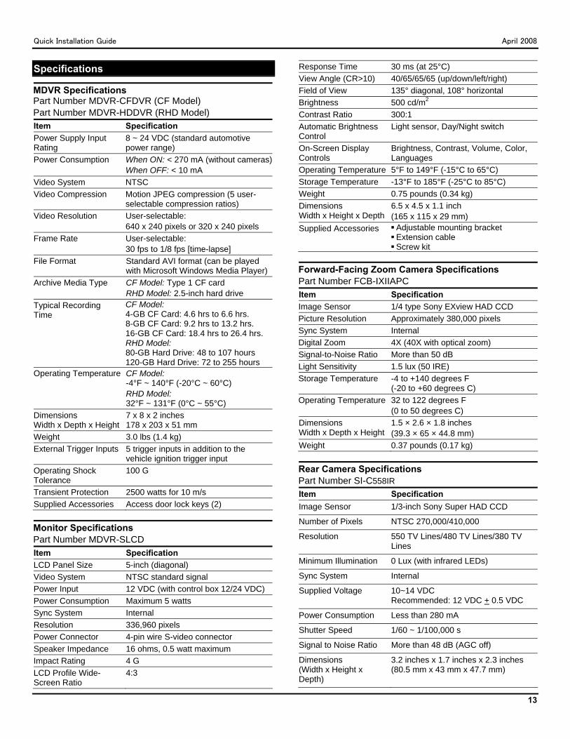
Specifications
MDVR Specifications Part Number MDVR-CFDVR (CF Model) Part Number MDVR-HDDVR (RHD Model) Item Specification Power Supply Input Rating
8 ~ 24 VDC (standard automotive power range)
Power Consumption When ON: < 270 mA (without cameras)When OFF: < 10 mA
Video System NTSC Video Compression Motion JPEG compression (5 user-
selectable compression ratios) Video Resolution User-selectable:
640 x 240 pixels or 320 x 240 pixels Frame Rate User-selectable:
30 fps to 1/8 fps [time-lapse] File Format Standard AVI format (can be played
with Microsoft Windows Media Player) Archive Media Type CF Model: Type 1 CF card
RHD Model: 2.5-inch hard drive Typical Recording Time
CF Model: 4-GB CF Card: 4.6 hrs to 6.6 hrs. 8-GB CF Card: 9.2 hrs to 13.2 hrs. 16-GB CF Card: 18.4 hrs to 26.4 hrs. RHD Model: 80-GB Hard Drive: 48 to 107 hours 120-GB Hard Drive: 72 to 255 hours
Operating Temperature CF Model: -4°F ~ 140°F (-20°C ~ 60°C) RHD Model: 32°F ~ 131°F (0°C ~ 55°C)
Dimensions Width x Depth x Height
7 x 8 x 2 inches 178 x 203 x 51 mm
Weight 3.0 lbs (1.4 kg) External Trigger Inputs 5 trigger inputs in addition to the
vehicle ignition trigger input Operating Shock Tolerance
100 G
Transient Protection 2500 watts for 10 m/s Supplied Accessories Access door lock keys (2)
Monitor Specifications Part Number MDVR-SLCDItem Specification LCD Panel Size 5-inch (diagonal) Video System NTSC standard signal Power Input 12 VDC (with control box 12/24 VDC) Power Consumption Maximum 5 watts Sync System Internal Resolution 336,960 pixels Power Connector 4-pin wire S-video connector Speaker Impedance 16 ohms, 0.5 watt maximum Impact Rating 4 G LCD Profile Wide-Screen Ratio
4:3
Response Time 30 ms (at 25°C) View Angle (CR>10) 40/65/65/65 (up/down/left/right) Field of View 135° diagonal, 108° horizontal Brightness 500 cd/m2 Contrast Ratio 300:1 Automatic Brightness Control
Light sensor, Day/Night switch
On-Screen Display Controls
Brightness, Contrast, Volume, Color, Languages
Operating Temperature 5°F to 149°F (-15°C to 65°C) Storage Temperature -13°F to 185°F (-25°C to 85°C) Weight 0.75 pounds (0.34 kg) Dimensions Width x Height x Depth
6.5 x 4.5 x 1.1 inch (165 x 115 x 29 mm)
Supplied Accessories Adjustable mounting bracket Extension cable Screw kit
Forward-Facing Zoom Camera Specifications Part Number FCB-IXIIAPC Item Specification Image Sensor 1/4 type Sony EXview HAD CCD Picture Resolution Approximately 380,000 pixels Sync System Internal Digital Zoom 4X (40X with optical zoom) Signal-to-Noise Ratio More than 50 dB Light Sensitivity 1.5 lux (50 IRE) Storage Temperature -4 to +140 degrees F
(-20 to +60 degrees C) Operating Temperature 32 to 122 degrees F
(0 to 50 degrees C) Dimensions Width x Depth x Height
1.5 × 2.6 × 1.8 inches (39.3 × 65 × 44.8 mm)
Weight 0.37 pounds (0.17 kg)
Rear Camera Specifications Part Number SI-C558IR Item Specification Image Sensor 1/3-inch Sony Super HAD CCD
Number of Pixels NTSC 270,000/410,000
Resolution 550 TV Lines/480 TV Lines/380 TV Lines
Minimum Illumination 0 Lux (with infrared LEDs)
Sync System Internal
Supplied Voltage 10~14 VDC Recommended: 12 VDC + 0.5 VDC
Power Consumption Less than 280 mA
Shutter Speed 1/60 ~ 1/100,000 s
Signal to Noise Ratio More than 48 dB (AGC off)
Dimensions (Width x Height x Depth)
3.2 inches x 1.7 inches x 2.3 inches (80.5 mm x 43 mm x 47.7 mm)
Quick Installation Guide April 2008
14
Wireless Audio System Specifications Charging Base/Receiver and Transmitter Part Number MDVR-AUDIO-PR2.4GRECItem Specification Operating Voltage Transmitter: 3.7 VDC
Receiver/Base: 12 VDC Frequency 2400 MHz Operating Range 1000 feet, line of sight Operating Temperature 10°F ~ 110°F (12°C ~ 43°C) Battery Rechargeable 3.7 VDC Lithium Ion
Warranty Information
LIMITED 1-YEAR NEW PRODUCT WARRANTY Costar Video Systems, LLC, makes the following limited warranty, which is effective at the time of the original end-user purchase.
NOTE: Optional warranty products are available for all Costar products and may be purchased at the time of the original end-user purchase or any time during the original Limited 1-Year New Product Warranty period.
Costar warrants this product against defects in materials for a period of 1 year after the date of purchase. During this period, Costar will repair or replace a defective product or part without charge to the customer. The customer must send the defective product or part to Costar or an authorized Costar dealer. The customer must pay for all transportation and insurance charges for sending the unit to be repaired. Costar’s total liability is limited to the original product cost.
Quick Installation Guide The customer should thoroughly read this guide before operating this product.
Customer’s Responsibility The above warranty is subject to the following conditions: Customer must notify Costar within 10 days of discovering
the defective product or part and provide a description of the defect and complete information about the manner of its discovery.
All warranty servicing of this product must be performed by Costar or an authorized servicing agent.
Warranty extends only to defects in materials as limited above. Warranty does not extend to any product or part that has been lost or discarded by the
customer; to damage to products or parts caused by misuse, accident, improper installation, improper maintenance, or use in violation of instructions furnished with the product; to units that have been altered or modified without authorization of Costar; to damage to products or parts thereof that have had the serial number removed, altered, defaced, or rendered illegible; or to any failure of the product to function caused by burglary, fire, flood, war, riot, civil commotion, Acts of God, or any other condition beyond the control of Costar.
Obtaining Warranty Service To obtain warranty service, the customer must contact the Costar Service and Warranty Manager at 888-694-7827 or 972-446-8844 to report a defective product. (The customer must report the model number and serial number if available.) The Service and Warranty Manager will assist in troubleshooting the problem and, if necessary, issue a return material authorization (RMA) number. The customer must include this number on the outside of each package shipped to Costar.
Important Packing and Shipping Instructions When a product requires service, only the affected component must be returned. The customer must use proper packing material to ensure against damage during shipping. Any shipping damage caused by improper packing is not covered under this warranty. In addition, the customer must include a return material authorization (RMA) number on the outside of each package shipped to Costar and a letter explaining the defect with the product.
How to Reach Us
If you have exhausted the information in this document and require further assistance or information, please contact Costar toll-free at 888-694-7827 or send an e-mail message requesting assistance to: [email protected].
Document Change Log
Document Version Document Filename Date
Changes Made
1.0 POLICE-RECORDER VER 1.0
June2008
New document
Quick Installation Guide April 2008
15
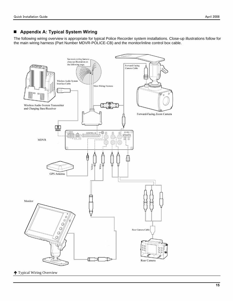
Appendix A: Typical System Wiring The following wiring overview is appropriate for typical Police Recorder system installations. Close-up illustrations follow for the main wiring harness (Part Number MDVR-POLICE-CB) and the monitor/inline control box cable.
Typical Wiring Overview
Quick Installation Guide April 2008
16
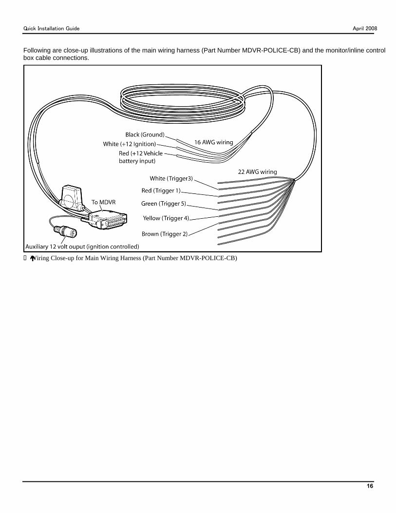
Following are close-up illustrations of the main wiring harness (Part Number MDVR-POLICE-CB) and the monitor/inline control box cable connections.
Wiring Close-up for Main Wiring Harness (Part Number MDVR-POLICE-CB)

Quick Installation Guide April 2008
17
Appendix B: Setup Menus The main menu includes the following menus: Setup Titles Trigger Setup Record Setup GPS Setup Camera Setup System Info
Setup Menu
The Setup menu allows user configuration as follows: Menu Item Description Comments Video In Select Controls the method by which
video is switched between cameras
MANUAL (Default) (controlled by MDVR front-panel UP and DOWN directional buttons)
SWITCHING (controlled by user-selectable dwell-time setting)
TRIGGER (controlled by trigger activation) MULTIPLEXED (both video inputs are recorded; video
output is unavailable in this mode) Video In Dwell Sets the duration of camera
input before automatic switching
Default: N/A
Units Controls the standard of measurement
Values: ENGLISH (Default) METRIC
Audio Volume Adjusts volume of audio output Values (in dB): -6, -3, 0, 3, 6, 9, 12 Default for Channel 1: 12 dB Default for Channel 2: 6 dB
Time Setup Initiates display of the menu that controls the system date, time, and adjustment for Daylight Saving Time
Default value for Daylight Saving Time is ON
Password Setup Allows user to press a sequence of front-panel buttons as a 6-character password for menu access (all front-panel keys may be used, except for the POWER button)
The MDVR prompts for password input when it is powered up initially. The default password is LEFT, RIGHT, LEFT, RIGHT, LEFT, RIGHT (using the front-panel directional buttons). The requirement for a password can be enabled or disabled for 4 levels of operation as follows: All Keys Power-off Playback Menus
Quick Installation Guide April 2008
18
Menu Item Description Comments Advanced Setup Initiates display of the
Advanced Setup menu Menu items: Restore Defaults (restores factory default settings) Erase Disk (deletes all files stored on the CF card or
removable hard drive) Network Setup (See following “Network Setup Sub-Menu”
section.) FTP/HTTP Setup (See following “FTP/HTTP Setup Sub-
Menu” section.)
Network Setup Sub-Menu
Menu Item Description Comments IP Configuration:
Method of setting IP address of the MDVR
Values: MANUAL (Default) (User sets IP address manually) AUTOMATIC (IP address is set automatically through DHCP)
IP Address:
MDVR network address User-selectable
Subnet Mask:
Used to determine the subnet to which MDVR IP address belongs
User-selectable
Gateway:
Address of network gateway (entrance point)
User-selectable
Primary DNS:
Address of primary DNS (Domain Name System)
User-selectable
Backup DNS:
Address of backup DNS User-selectable
Power Off Command:
Causes the MDVR to remain powered ON for 2 hours after the vehicle ignition is turned off (allows for remote FTP data download)
User-selectable
Save:
Saves network setup information
None
FTP/HTTP Setup Sub-Menu
Menu Item Description Comments Username Case-sensitive user name
used when connecting with a web browser
Default: dvrStart
Password Case-sensitive password used when connecting with a web browser
Default: myPass40
HTTP Port Communications port Default: 80
Quick Installation Guide April 2008
19
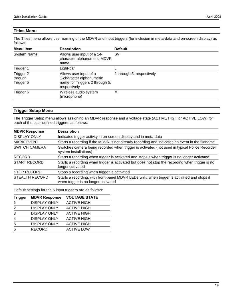
Titles Menu
The Titles menu allows user naming of the MDVR and input triggers (for inclusion in meta-data and on-screen display) as follows: Menu Item Description Default System Name Allows user input of a 14-
character alphanumeric MDVR name
SV
Trigger 1 Light-bar L Trigger 2 through Trigger 5
Allows user input of a 1-character alphanumeric name for Triggers 2 through 5, respectively
2 through 5, respectively
Trigger 6 Wireless audio system (microphone)
M
Trigger Setup Menu
The Trigger Setup menu allows assigning an MDVR response and a voltage state (ACTIVE HIGH or ACTIVE LOW) for each of the user-defined triggers, as follows:
MDVR Response Description DISPLAY ONLY Indicates trigger activity in on-screen display and in meta-data MARK EVENT Starts a recording if the MDVR is not already recording and indicates an event in the filename SWITCH CAMERA Switches camera being recorded when trigger is activated (not used in typical Police Recorder
system installations) RECORD Starts a recording when trigger is activated and stops it when trigger is no longer activated START RECORD Starts a recording when trigger is activated but does not stop the recording when trigger is no
longer activated STOP RECORD Stops a recording when trigger is activated STEALTH RECORD Starts a recording, with front-panel MDVR LEDs unlit, when trigger is activated and stops it
when trigger is no longer activated
Default settings for the 6 input triggers are as follows:
Trigger MDVR Response VOLTAGE STATE 1 DISPLAY ONLY ACTIVE HIGH 2 DISPLAY ONLY ACTIVE HIGH 3 DISPLAY ONLY ACTIVE HIGH 4 DISPLAY ONLY ACTIVE HIGH 5 DISPLAY ONLY ACTIVE HIGH 6 RECORD ACTIVE LOW
Quick Installation Guide April 2008
20
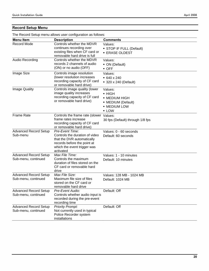
Record Setup Menu
The Record Setup menu allows user configuration as follows: Menu Item Description Comments Record Mode Controls whether the MDVR
continues recording over existing files when CF card or removable hard drive is full
Values: STOP IF FULL (Default) ERASE OLDEST
Audio Recording Controls whether the MDVR records 2 channels of audio (ON) or no audio (OFF)
Values: ON (Default) OFF
Image Size Controls image resolution (lower resolution increases recording capacity of CF card or removable hard drive)
Values: 640 x 240 320 x 240 (Default)
Image Quality Controls image quality (lower image quality increases recording capacity of CF card or removable hard drive)
Values: HIGH MEDIUM HIGH MEDIUM (Default) MEDIUM LOW LOW
Frame Rate Controls the frame rate (slower frame rates increase recording capacity of CF card or removable hard drive)
Values: 30 fps (Default) through 1/8 fps
Advanced Record Setup Sub-menu
Pre-Event Time: Controls the duration of video that the DVR automatically records before the point at which the event trigger was activated
Values: 0 - 60 seconds Default: 60 seconds
Advanced Record Setup Sub-menu, continued
Max File Time: Controls the maximum duration of files stored on the CF card or removable hard drive
Values: 1 - 10 minutes Default: 10 minutes
Advanced Record Setup Sub-menu, continued
Max File Size: Maximum file size of files stored on the CF card or removable hard drive
Values: 128 MB - 1024 MB Default: 1024 MB
Advanced Record Setup Sub-menu, continued
Pre-Event Audio: Controls whether audio input is recorded during the pre-event recording time
Default: Off
Advanced Record Setup Sub-menu, continued
Priority Prompt: Not currently used in typical Police Recorder system installations
Default: Off
Quick Installation Guide April 2008
21
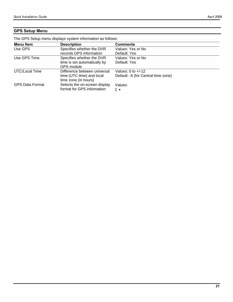
GPS Setup Menu
The GPS Setup menu displays system information as follows: Menu Item Description Comments Use GPS Specifies whether the DVR
records GPS information Values: Yes or No Default: Yes
Use GPS Time Specifies whether the DVR time is set automatically by GPS module
Values: Yes or No Default: Yes
UTC/Local Time Difference between universal time (UTC time) and local time zone (in hours)
Values: 0 to +/-12 Default: -6 (for Central time zone)
GPS Data Format Selects the on-screen display format for GPS information
Values: DDD:MM:SS (degrees: minutes: seconds) DDD:MM:mm (degrees: minutes: decimal minutes) DDD.ddddd (degrees: decimal degrees)
Camera Setup Menu
The Camera Setup menu displays camera setup information as follows: Menu Item Description Comments Camera Protocol Sets the interface protocol for
the system Values: SI, VISCA Default: VISCA
One Touch Zoom Sets the maximum zoom level for the forward-facing zoom camera
Values: 25%, 50%, 75%, 100% Default: 75%
Focus Controls how the focus is adjusted
Values: AUTO, MANUAL Default: AUTO
Sensitivity Adjusts the shutter sensitivity for better quality in low light
Values: LOW, MEDIUM, HIGH Default: HIGH
Slow Shutter Adjusts the shutter speed to allow more or less light
Values: ON or OFF Default: OFF
System Info Menu
The System Info menu displays system information as follows: Menu Item Description Disk Capacity Storage capacity of the CF card or removable hard drive Percent Used Percentage of used space on the CF card or removable hard drive Percent Free Percentage of free space on the CF card or removable hard drive Firmware Version Firmware version level MAC Address MAC (media access control) address of the DVR