pole-safe - coral sales company washer per astm f436 . pole base plate . 3x14x27mm...
TRANSCRIPT

E n g i n e e r e d
I n n o v a t i v e
P r o d u c t s & S e r v i c e s
F o r Tr a n s p o r t a t i o n
Pole-SafeBreakaway Lightpole Support Systems
20 Jones Street, New Rochelle, NY 10801 ● Phone: 914.636.1000 ● Fax: 914.636.1282 ● Web: transpo.com
Design Book
®
TRANSPOINDUSTRIES, Inc.
® Pole-Safe®
Breakaway Light Pole Support System
Saving LivesBreakaway Light Pole Support System
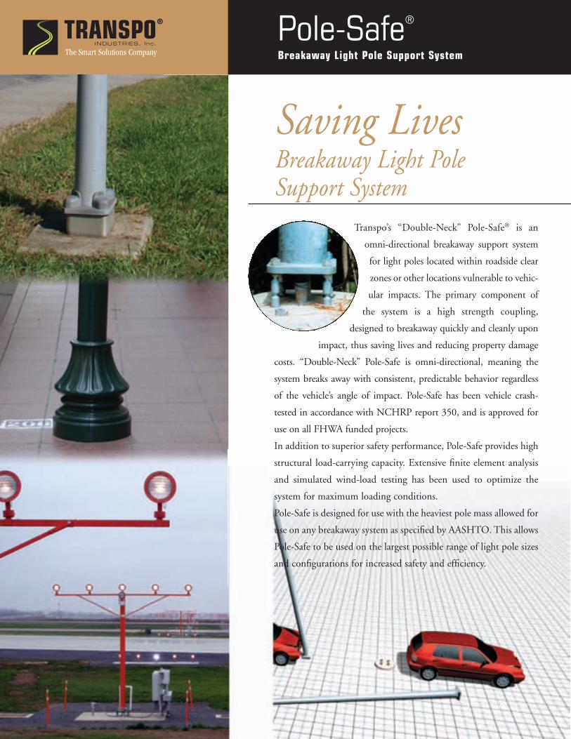
Transpo’s “Double-Neck” Pole-Safe® is an
omni-directional breakaway support system
for light poles located within roadside clear
zones or other locations vulnerable to vehic-
ular impacts. The primary component of
the system is a high strength coupling,
designed to breakaway quickly and cleanly upon
impact, thus saving lives and reducing property damage
costs. “Double-Neck” Pole-Safe is omni-directional, meaning the
system breaks away with consistent, predictable behavior regardless
of the vehicle’s angle of impact. Pole-Safe has been vehicle crash-
tested in accordance with NCHRP report 350, and is approved for
use on all FHWA funded projects.
In addition to superior safety performance, Pole-Safe provides high
structural load-carrying capacity. Extensive finite element analysis
and simulated wind-load testing has been used to optimize the
system for maximum loading conditions.
Pole-Safe is designed for use with the heaviest pole mass allowed for
use on any breakaway system as specified by AASHTO. This allows
Pole-Safe to be used on the largest possible range of light pole sizes
and configurations for increased safety and efficiency.
The Smart Solutions Company

TRANSPOThe Smart Solutions Company
INDUSTRIES, Inc.
®
Pole-Safe®
Breakaway Light Pole Support System
Features and Advantages
Superior Breakaway Performance: The precisely
machined geometry of the Pole-Safe coupling design causes
the system to fracture safely at relatively low force and ener-
gy levels. This unique capacity is better than AASHTO’s
requirements for impact velocity change. The low stub pro-
jection after impact eliminates under carriage damage to
vehicle, thus reducing the risk of fire.
High Structural Capacity: Pole-Safe is available in a variety
of models, designed to support many different pole configu-
rations subjected to various loading conditions. The high
strength coupling design offers exceptional resistance to
forces created by wind and dead loads. All Pole-Safe crash
tests were conducted using a 55’ high, 930 lb. Pole, which is
the maximum allowable pole mass as specified by AASHTO.
The unique physical properties and breakaway performance
of “Double-Neck” Pole-Safe gives designers the greatest
flexibility in sizing poles for specific lighting requirements.
High Durability: All Pole-Safe couplings and hardware
are hot-dip galvanized in accordance with ASTM A153 to
provide proven corrosion protection in harsh roadside
environments. Additionally, independent fatigue testing
has demonstrated that Pole-Safe couplings are capable of
withstanding more than 2 million loading cycles with no
reduction in structural capacity.
Easy to Install and Maintain:
No special tools or equipment are
required to properly install and
maintain Pole-Safe. All compo-
nents are easily secured using the
American Institute of Steel
Construction (AISC) Turn-of-
Model Selection:Pole-Safe Model 4000 Series:
For use with externally threaded anchor bolts.
Pole-Safe Model No. Anchor Bolt Diameter
4062 5/8 in (16 mm)
4075 3/4 in (19 mm)
4100 1 in (25 mm)
4125 1-1/4 in (32 mm)
Pole-Safe Model 5000 Series:
For use with Transpo foundation anchor inserts.
Pole-Safe Model No. Anchor Socket Diameter
5062 5/8 in (16 mm)
5075 3/4 in (19 mm)
5100 1 in (25 mm)
5125* 1-1/4 in (32 mm)
* Special order.
Nut Tightening method, which eliminates the need for pre-
cise torque levels on bolts.
Low Cost: Pole-Safe is the lowest cost breakaway system
for light poles. Low initial cost coupled with high structur-
al capacity and zero maintenance makes Pole-Safe the most
cost-effective solution for all breakaway light poles.
TESTED AND APPROVED TO NCHRP 350
U.S. Patent Nos. 5,474,408 and 6,056,471
20 Jones Street, New Rochelle, NY 10801
Tel: 914-636-1000 • Fax: 914-636-1282
www.transpo.com � [email protected]
TRANSPOINDUSTRIES, Inc .
®
900 l/ 20 00

25 +/- 3 mm (1” +/- 1/8”)
144 mm (5-11/16”)
44 mm (1-3/4”)
1/2”-13 UNC (13 mm) Nut per ASTM A563 Grade DH 3x14x27mm (1/8”x17/32”x1-1/16”) Flat Washer per ASTM F436 Pole Base Plate 3x14x27mm (1/8”x17/32”x1-1/16”) Flat Washer per ASTM F436 Upper Wrench Flats Double-NeckTM Pole-Safe® Coupling, Model No. 4050 4 per Pole or Post, Typical Lower Wrench Flats Galvanized Steel Shim 14g and/or 18g Thickness (if required for leveling) 3x14x27mm (1/8”x17/32”x1-1/16”) Flat Washer per ASTM F436 Galvanized Anchor Bolt 1/2”-13 UNC (13 mm) Threads (Anchor Bolts supplied by others) Melted and Manufactured in the USA Patent Nos. 5,474,408 & 6,056,471 1/14
SPECIFICATIONS Performance Criteria:
1. Double-NeckTM Pole-Safe® conforms to AASHTO “Standard Specifications for Structural Supports for Highway Signs, Luminaires and Traffic Signals.”
2. Double-NeckTM Pole-Safe® has been crash-tested and FHWA approved in accordance with the requirements of NCHRP Report 350, “Recommended Procedures for the Safety Performance Evaluation of Highway Features.”
Physical Properties per Coupling:
1. Ultimate Tensile Strength = 53.8 kN (12.1 kips), minimum.
2. Tensile Yield Strength = 46.5 kN (10.4 kips), minimum.
3. Ultimate Restrained Shear Strength = 2.6 kN (0.6 kips), minimum.
4. Ultimate Restrained Shear Strength = 4.4 kN (1.0 kips), maximum.
Corrosion Protection:
1. All Double-NeckTM Pole-Safe® couplings, nuts, bolts, and washers are galvanized after fabrication in accordance with ASTM A153. All leveling shims are galvanized after fabrication in accordance with ASTM A653.
Pole-Safe® Model No. 4050 Breakaway Support System for Light Poles
20 Jones Street New Rochelle, NY 10801 914-636-1000 www.transpo.com

Pole-Safe® Model No. 4050 Breakaway Support System for Light Poles
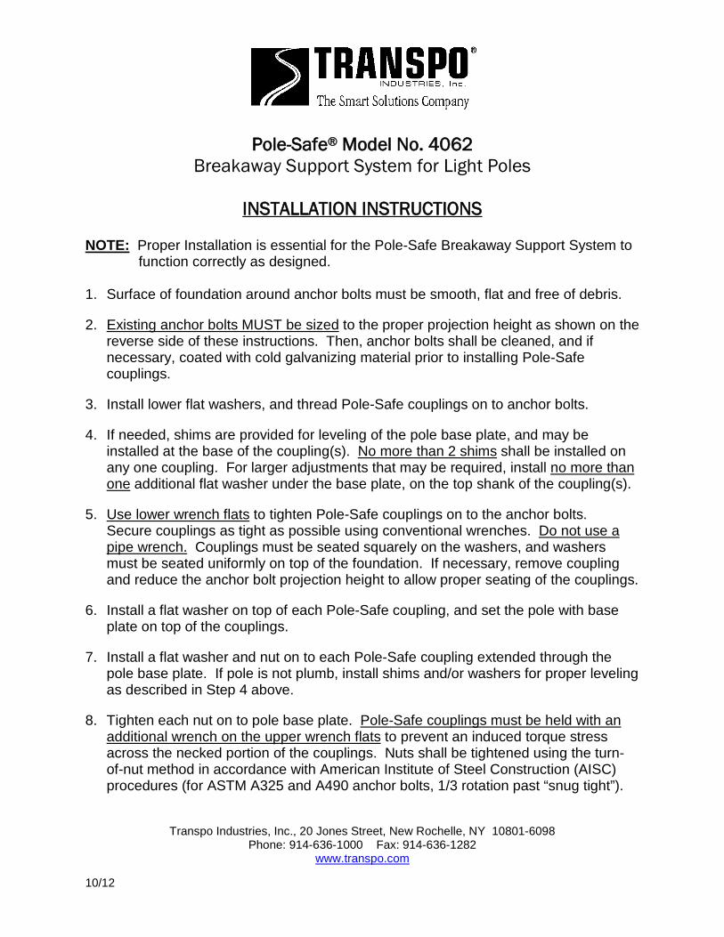
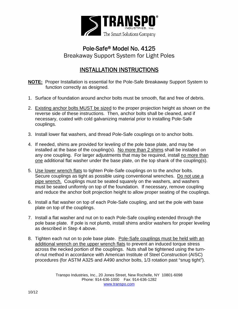
INSTALLATION INSTRUCTIONS
NOTE: Proper Installation is essential for the Pole-Safe Breakaway Support System to
function correctly as designed. 1. Surface of foundation around anchor bolts must be smooth, flat and free of debris.
2. Existing anchor bolts MUST be sized to the proper projection height as shown on the reverse side of these instructions. Then, anchor bolts shall be cleaned, and if necessary, coated with cold galvanizing material prior to installing Pole-Safe couplings.
3. Install lower flat washers, and thread Pole-Safe couplings on to anchor bolts.
4. If needed, shims are provided for leveling of the pole base plate, and may be installed at the base of the coupling(s). No more than 2 shims shall be installed on any one coupling. For larger adjustments that may be required, install no more than one additional flat washer under the base plate, on the top shank of the coupling(s).
5. Use lower wrench flats to tighten Pole-Safe couplings on to the anchor bolts. Secure couplings as tight as possible using conventional wrenches. Do not use a pipe wrench. Couplings must be seated squarely on the washers, and washers must be seated uniformly on top of the foundation. If necessary, remove coupling and reduce the anchor bolt projection height to allow proper seating of the couplings.
6. Install a flat washer on top of each Pole-Safe coupling, and set the pole with base plate on top of the couplings.
7. Install a flat washer and nut on to each Pole-Safe coupling extended through the pole base plate. If pole is not plumb, install shims and/or washers for proper leveling as described in Step 4 above.
8. Tighten each nut on to pole base plate. Pole-Safe couplings must be held with an additional wrench on the upper wrench flats to prevent an induced torque stress across the necked portion of the couplings. Nuts shall be tightened using the turn-of-nut method in accordance with American Institute of Steel Construction (AISC) procedures (for ASTM A325 and A490 anchor bolts, 1/3 rotation past “snug tight”).
Transpo Industries, Inc., 20 Jones Street, New Rochelle, NY 10801-6098
Phone: 914-636-1000 Fax: 914-636-1282 www.transpo.com
10/12

29 +/- 3 mm (1-1/8” +/- 1/8”)
148 mm (5-13/16”)
51 mm (2”)
5/8”-11 UNC (16 mm) Nut per ASTM A563 Grade DH 3x17x33mm (1/8”x11/16”x1-5/16”) Flat Washer per ASTM F436 Pole Base Plate 3x17x33mm (1/8”x11/16”x1-5/16”) Flat Washer per ASTM F436 Upper Wrench Flats Double-NeckTM Pole-Safe® Coupling, Model No. 4062 4 per Pole, Typical Lower Wrench Flats Galvanized Steel Shim 14g and/or 18g Thickness (if required for leveling) 3x17x33mm (1/8”x11/16”x1-5/16”) Flat Washer per ASTM F436 Galvanized Anchor Bolt 5/8”-11 UNC (16 mm) Threads (Anchor Bolts supplied by others) Melted and Manufactured in the USA Patent Nos. 5,474,408 & 6,056,471 1/14
SPECIFICATIONS Performance Criteria:
1. Double-NeckTM Pole-Safe® conforms to AASHTO “Standard Specifications for Structural Supports for Highway Signs, Luminaires and Traffic Signals.”
2. Double-NeckTM Pole-Safe® has been crash-tested and FHWA approved in accordance with the requirements of NCHRP Report 350, “Recommended Procedures for the Safety Performance Evaluation of Highway Features.”
Physical Properties per Coupling:
1. Ultimate Tensile Strength = 101.9 kN (22.8 kips), minimum.
2. Tensile Yield Strength = 88.3 kN (19.8 kips), minimum.
3. Ultimate Restrained Shear Strength = 6.6 kN (1.5 kips), minimum.
4. Ultimate Restrained Shear Strength = 11.1 kN (2.5 kips), maximum.
Corrosion Protection:
1. All Double-NeckTM Pole-Safe® couplings, nuts, bolts, and washers are galvanized after fabrication in accordance with ASTM A153. All leveling shims are galvanized after fabrication in accordance with ASTM A653.
Pole-Safe® Model No. 4062 Breakaway Support System for Light Poles
20 Jones Street New Rochelle, NY 10801 914-636-1000 www.transpo.com
Pole-Safe® Model No. 4062 Breakaway Support System for Light Poles
INSTALLATION INSTRUCTIONS
NOTE: Proper Installation is essential for the Pole-Safe Breakaway Support System to
function correctly as designed. 1. Surface of foundation around anchor bolts must be smooth, flat and free of debris.
2. Existing anchor bolts MUST be sized to the proper projection height as shown on the reverse side of these instructions. Then, anchor bolts shall be cleaned, and if necessary, coated with cold galvanizing material prior to installing Pole-Safe couplings.
3. Install lower flat washers, and thread Pole-Safe couplings on to anchor bolts.
4. If needed, shims are provided for leveling of the pole base plate, and may be installed at the base of the coupling(s). No more than 2 shims shall be installed on any one coupling. For larger adjustments that may be required, install no more than one additional flat washer under the base plate, on the top shank of the coupling(s).
5. Use lower wrench flats to tighten Pole-Safe couplings on to the anchor bolts. Secure couplings as tight as possible using conventional wrenches. Do not use a pipe wrench. Couplings must be seated squarely on the washers, and washers must be seated uniformly on top of the foundation. If necessary, remove coupling and reduce the anchor bolt projection height to allow proper seating of the couplings.
6. Install a flat washer on top of each Pole-Safe coupling, and set the pole with base plate on top of the couplings.
7. Install a flat washer and nut on to each Pole-Safe coupling extended through the pole base plate. If pole is not plumb, install shims and/or washers for proper leveling as described in Step 4 above.
8. Tighten each nut on to pole base plate. Pole-Safe couplings must be held with an additional wrench on the upper wrench flats to prevent an induced torque stress across the necked portion of the couplings. Nuts shall be tightened using the turn-of-nut method in accordance with American Institute of Steel Construction (AISC) procedures (for ASTM A325 and A490 anchor bolts, 1/3 rotation past “snug tight”).
Transpo Industries, Inc., 20 Jones Street, New Rochelle, NY 10801-6098
Phone: 914-636-1000 Fax: 914-636-1282 www.transpo.com
10/12
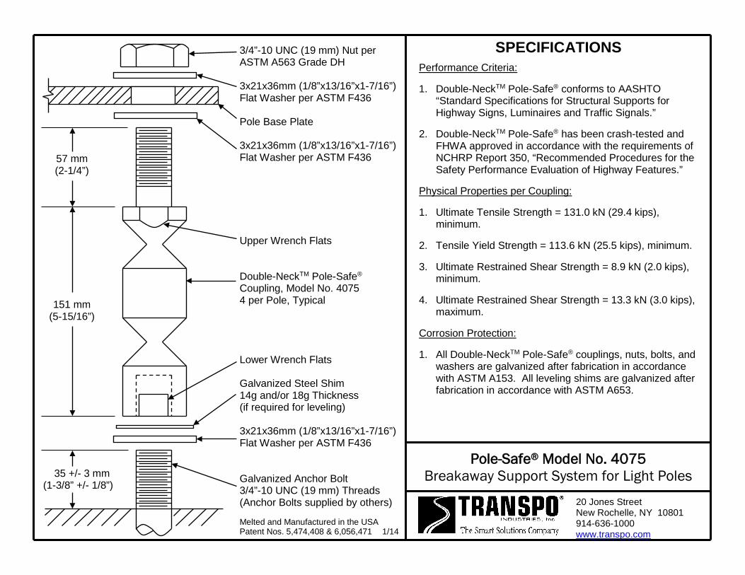
35 +/- 3 mm (1-3/8” +/- 1/8”)
151 mm (5-15/16”)
57 mm (2-1/4”)
3/4”-10 UNC (19 mm) Nut per ASTM A563 Grade DH 3x21x36mm (1/8”x13/16”x1-7/16”) Flat Washer per ASTM F436 Pole Base Plate 3x21x36mm (1/8”x13/16”x1-7/16”) Flat Washer per ASTM F436 Upper Wrench Flats Double-NeckTM Pole-Safe® Coupling, Model No. 4075 4 per Pole, Typical Lower Wrench Flats Galvanized Steel Shim 14g and/or 18g Thickness (if required for leveling) 3x21x36mm (1/8”x13/16”x1-7/16”) Flat Washer per ASTM F436 Galvanized Anchor Bolt 3/4”-10 UNC (19 mm) Threads (Anchor Bolts supplied by others) Melted and Manufactured in the USA Patent Nos. 5,474,408 & 6,056,471 1/14
SPECIFICATIONS Performance Criteria:
1. Double-NeckTM Pole-Safe® conforms to AASHTO “Standard Specifications for Structural Supports for Highway Signs, Luminaires and Traffic Signals.”
2. Double-NeckTM Pole-Safe® has been crash-tested and FHWA approved in accordance with the requirements of NCHRP Report 350, “Recommended Procedures for the Safety Performance Evaluation of Highway Features.”
Physical Properties per Coupling:
1. Ultimate Tensile Strength = 131.0 kN (29.4 kips), minimum.
2. Tensile Yield Strength = 113.6 kN (25.5 kips), minimum.
3. Ultimate Restrained Shear Strength = 8.9 kN (2.0 kips), minimum.
4. Ultimate Restrained Shear Strength = 13.3 kN (3.0 kips), maximum.
Corrosion Protection:
1. All Double-NeckTM Pole-Safe® couplings, nuts, bolts, and washers are galvanized after fabrication in accordance with ASTM A153. All leveling shims are galvanized after fabrication in accordance with ASTM A653.
Pole-Safe® Model No. 4075 Breakaway Support System for Light Poles
20 Jones Street New Rochelle, NY 10801 914-636-1000 www.transpo.com
Pole-Safe® Model No. 4075 Breakaway Support System for Light Poles
INSTALLATION INSTRUCTIONS
NOTE: Proper Installation is essential for the Pole-Safe Breakaway Support System to
function correctly as designed. 1. Surface of foundation around anchor bolts must be smooth, flat and free of debris.
2. Existing anchor bolts MUST be sized to the proper projection height as shown on the reverse side of these instructions. Then, anchor bolts shall be cleaned, and if necessary, coated with cold galvanizing material prior to installing Pole-Safe couplings.
3. Install lower flat washers, and thread Pole-Safe couplings on to anchor bolts.
4. If needed, shims are provided for leveling of the pole base plate, and may be installed at the base of the coupling(s). No more than 2 shims shall be installed on any one coupling. For larger adjustments that may be required, install no more than one additional flat washer under the base plate, on the top shank of the coupling(s).
5. Use lower wrench flats to tighten Pole-Safe couplings on to the anchor bolts. Secure couplings as tight as possible using conventional wrenches. Do not use a pipe wrench. Couplings must be seated squarely on the washers, and washers must be seated uniformly on top of the foundation. If necessary, remove coupling and reduce the anchor bolt projection height to allow proper seating of the couplings.
6. Install a flat washer on top of each Pole-Safe coupling, and set the pole with base plate on top of the couplings.
7. Install a flat washer and nut on to each Pole-Safe coupling extended through the pole base plate. If pole is not plumb, install shims and/or washers for proper leveling as described in Step 4 above.
8. Tighten each nut on to pole base plate. Pole-Safe couplings must be held with an additional wrench on the upper wrench flats to prevent an induced torque stress across the necked portion of the couplings. Nuts shall be tightened using the turn-of-nut method in accordance with American Institute of Steel Construction (AISC) procedures (for ASTM A325 and A490 anchor bolts, 1/3 rotation past “snug tight”).
Transpo Industries, Inc., 20 Jones Street, New Rochelle, NY 10801-6098
Phone: 914-636-1000 Fax: 914-636-1282 www.transpo.com
10/12
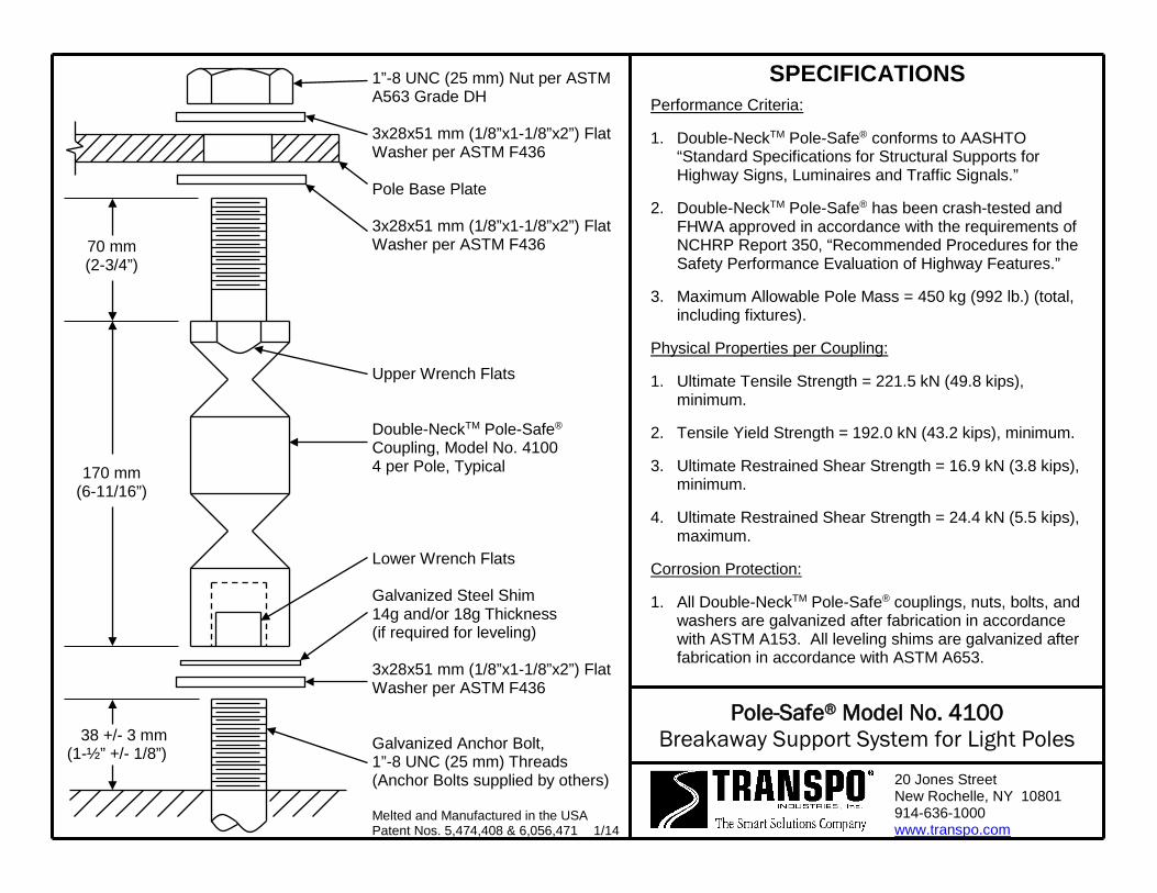
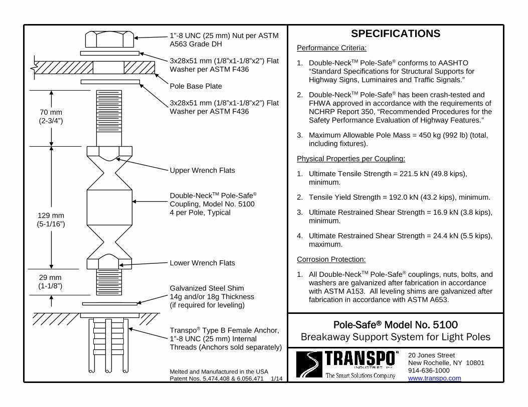
38 +/- 3 mm (1-½” +/- 1/8”)
170 mm (6-11/16”)
70 mm (2-3/4”)
1”-8 UNC (25 mm) Nut per ASTM A563 Grade DH 3x28x51 mm (1/8”x1-1/8”x2”) Flat Washer per ASTM F436 Pole Base Plate 3x28x51 mm (1/8”x1-1/8”x2”) Flat Washer per ASTM F436 Upper Wrench Flats Double-NeckTM Pole-Safe® Coupling, Model No. 4100 4 per Pole, Typical Lower Wrench Flats Galvanized Steel Shim 14g and/or 18g Thickness (if required for leveling) 3x28x51 mm (1/8”x1-1/8”x2”) Flat Washer per ASTM F436 Galvanized Anchor Bolt, 1”-8 UNC (25 mm) Threads (Anchor Bolts supplied by others) Melted and Manufactured in the USA Patent Nos. 5,474,408 & 6,056,471 1/14
SPECIFICATIONS Performance Criteria:
1. Double-NeckTM Pole-Safe® conforms to AASHTO “Standard Specifications for Structural Supports for Highway Signs, Luminaires and Traffic Signals.”
2. Double-NeckTM Pole-Safe® has been crash-tested and FHWA approved in accordance with the requirements of NCHRP Report 350, “Recommended Procedures for the Safety Performance Evaluation of Highway Features.”
3. Maximum Allowable Pole Mass = 450 kg (992 lb.) (total, including fixtures).
Physical Properties per Coupling:
1. Ultimate Tensile Strength = 221.5 kN (49.8 kips), minimum.
2. Tensile Yield Strength = 192.0 kN (43.2 kips), minimum.
3. Ultimate Restrained Shear Strength = 16.9 kN (3.8 kips), minimum.
4. Ultimate Restrained Shear Strength = 24.4 kN (5.5 kips), maximum.
Corrosion Protection:
1. All Double-NeckTM Pole-Safe® couplings, nuts, bolts, and washers are galvanized after fabrication in accordance with ASTM A153. All leveling shims are galvanized after fabrication in accordance with ASTM A653.
Pole-Safe® Model No. 4100 Breakaway Support System for Light Poles
20 Jones Street New Rochelle, NY 10801 914-636-1000 www.transpo.com

Pole-Safe® Model No. 4100 Breakaway Support System for Light Poles
INSTALLATION INSTRUCTIONS
NOTE: Proper Installation is essential for the Pole-Safe Breakaway Support System to
function correctly as designed. 1. Surface of foundation around anchor bolts must be smooth, flat and free of debris.
2. Existing anchor bolts MUST be sized to the proper projection height as shown on the reverse side of these instructions. Then, anchor bolts shall be cleaned, and if necessary, coated with cold galvanizing material prior to installing Pole-Safe couplings.
3. Install lower flat washers, and thread Pole-Safe couplings on to anchor bolts.
4. If needed, shims are provided for leveling of the pole base plate, and may be installed at the base of the coupling(s). No more than 2 shims shall be installed on any one coupling. For larger adjustments that may be required, install no more than one additional flat washer under the base plate, on the top shank of the coupling(s).
5. Use lower wrench flats to tighten Pole-Safe couplings on to the anchor bolts. Secure couplings as tight as possible using conventional wrenches. Do not use a pipe wrench. Couplings must be seated squarely on the washers, and washers must be seated uniformly on top of the foundation. If necessary, remove coupling and reduce the anchor bolt projection height to allow proper seating of the couplings.
6. Install a flat washer on top of each Pole-Safe coupling, and set the pole with base plate on top of the couplings.
7. Install a flat washer and nut on to each Pole-Safe coupling extended through the pole base plate. If pole is not plumb, install shims and/or washers for proper leveling as described in Step 4 above.
8. Tighten each nut on to pole base plate. Pole-Safe couplings must be held with an additional wrench on the upper wrench flats to prevent an induced torque stress across the necked portion of the couplings. Nuts shall be tightened using the turn-of-nut method in accordance with American Institute of Steel Construction (AISC) procedures (for ASTM A325 and A490 anchor bolts, 1/3 rotation past “snug tight”).
Transpo Industries, Inc., 20 Jones Street, New Rochelle, NY 10801-6098
Phone: 914-636-1000 Fax: 914-636-1282 www.transpo.com
10/12
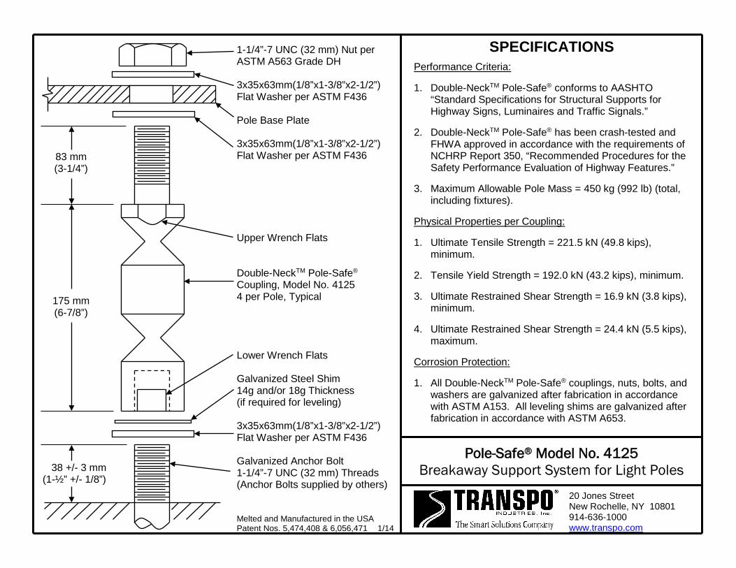
38 +/- 3 mm (1-½” +/- 1/8”)
175 mm (6-7/8”)
83 mm (3-1/4”)
1-1/4”-7 UNC (32 mm) Nut per ASTM A563 Grade DH 3x35x63mm(1/8”x1-3/8”x2-1/2”) Flat Washer per ASTM F436 Pole Base Plate 3x35x63mm(1/8”x1-3/8”x2-1/2”) Flat Washer per ASTM F436 Upper Wrench Flats Double-NeckTM Pole-Safe® Coupling, Model No. 4125 4 per Pole, Typical Lower Wrench Flats Galvanized Steel Shim 14g and/or 18g Thickness (if required for leveling) 3x35x63mm(1/8”x1-3/8”x2-1/2”) Flat Washer per ASTM F436 Galvanized Anchor Bolt 1-1/4”-7 UNC (32 mm) Threads (Anchor Bolts supplied by others) Melted and Manufactured in the USA Patent Nos. 5,474,408 & 6,056,471 1/14
SPECIFICATIONS
Performance Criteria:
1. Double-NeckTM Pole-Safe® conforms to AASHTO “Standard Specifications for Structural Supports for Highway Signs, Luminaires and Traffic Signals.”
2. Double-NeckTM Pole-Safe® has been crash-tested and FHWA approved in accordance with the requirements of NCHRP Report 350, “Recommended Procedures for the Safety Performance Evaluation of Highway Features.”
3. Maximum Allowable Pole Mass = 450 kg (992 lb) (total, including fixtures).
Physical Properties per Coupling:
1. Ultimate Tensile Strength = 221.5 kN (49.8 kips), minimum.
2. Tensile Yield Strength = 192.0 kN (43.2 kips), minimum.
3. Ultimate Restrained Shear Strength = 16.9 kN (3.8 kips), minimum.
4. Ultimate Restrained Shear Strength = 24.4 kN (5.5 kips), maximum.
Corrosion Protection:
1. All Double-NeckTM Pole-Safe® couplings, nuts, bolts, and washers are galvanized after fabrication in accordance with ASTM A153. All leveling shims are galvanized after fabrication in accordance with ASTM A653.
Pole-Safe® Model No. 4125 Breakaway Support System for Light Poles
20 Jones Street New Rochelle, NY 10801 914-636-1000 www.transpo.com
Pole-Safe® Model No. 4125 Breakaway Support System for Light Poles
INSTALLATION INSTRUCTIONS
NOTE: Proper Installation is essential for the Pole-Safe Breakaway Support System to
function correctly as designed. 1. Surface of foundation around anchor bolts must be smooth, flat and free of debris.
2. Existing anchor bolts MUST be sized to the proper projection height as shown on the reverse side of these instructions. Then, anchor bolts shall be cleaned, and if necessary, coated with cold galvanizing material prior to installing Pole-Safe couplings.
3. Install lower flat washers, and thread Pole-Safe couplings on to anchor bolts.
4. If needed, shims are provided for leveling of the pole base plate, and may be installed at the base of the coupling(s). No more than 2 shims shall be installed on any one coupling. For larger adjustments that may be required, install no more than one additional flat washer under the base plate, on the top shank of the coupling(s).
5. Use lower wrench flats to tighten Pole-Safe couplings on to the anchor bolts. Secure couplings as tight as possible using conventional wrenches. Do not use a pipe wrench. Couplings must be seated squarely on the washers, and washers must be seated uniformly on top of the foundation. If necessary, remove coupling and reduce the anchor bolt projection height to allow proper seating of the couplings.
6. Install a flat washer on top of each Pole-Safe coupling, and set the pole with base plate on top of the couplings.
7. Install a flat washer and nut on to each Pole-Safe coupling extended through the pole base plate. If pole is not plumb, install shims and/or washers for proper leveling as described in Step 4 above.
8. Tighten each nut on to pole base plate. Pole-Safe couplings must be held with an additional wrench on the upper wrench flats to prevent an induced torque stress across the necked portion of the couplings. Nuts shall be tightened using the turn-of-nut method in accordance with American Institute of Steel Construction (AISC) procedures (for ASTM A325 and A490 anchor bolts, 1/3 rotation past “snug tight”).
Transpo Industries, Inc., 20 Jones Street, New Rochelle, NY 10801-6098
Phone: 914-636-1000 Fax: 914-636-1282 www.transpo.com
10/12
22 mm (7/8”)
111 mm (4-3/8”)
51 mm (2”)
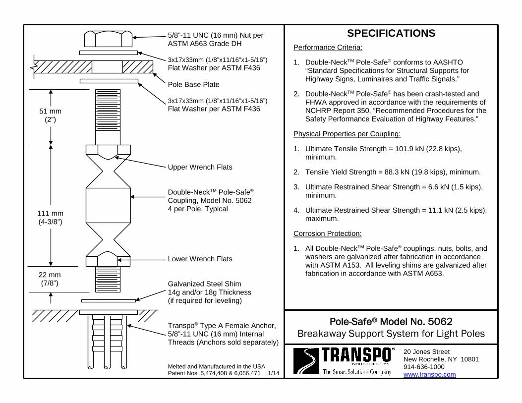
5/8”-11 UNC (16 mm) Nut per ASTM A563 Grade DH 3x17x33mm (1/8”x11/16”x1-5/16”) Flat Washer per ASTM F436 Pole Base Plate 3x17x33mm (1/8”x11/16”x1-5/16”) Flat Washer per ASTM F436 Upper Wrench Flats Double-NeckTM Pole-Safe® Coupling, Model No. 5062 4 per Pole, Typical Lower Wrench Flats Galvanized Steel Shim 14g and/or 18g Thickness (if required for leveling) Transpo® Type A Female Anchor, 5/8”-11 UNC (16 mm) Internal Threads (Anchors sold separately)
Melted and Manufactured in the USA Patent Nos. 5,474,408 & 6,056,471 1/14
SPECIFICATIONS Performance Criteria:
1. Double-NeckTM Pole-Safe® conforms to AASHTO “Standard Specifications for Structural Supports for Highway Signs, Luminaires and Traffic Signals.”
2. Double-NeckTM Pole-Safe® has been crash-tested and FHWA approved in accordance with the requirements of NCHRP Report 350, “Recommended Procedures for the Safety Performance Evaluation of Highway Features.”
Physical Properties per Coupling:
1. Ultimate Tensile Strength = 101.9 kN (22.8 kips), minimum.
2. Tensile Yield Strength = 88.3 kN (19.8 kips), minimum.
3. Ultimate Restrained Shear Strength = 6.6 kN (1.5 kips), minimum.
4. Ultimate Restrained Shear Strength = 11.1 kN (2.5 kips), maximum.
Corrosion Protection:
1. All Double-NeckTM Pole-Safe® couplings, nuts, bolts, and washers are galvanized after fabrication in accordance with ASTM A153. All leveling shims are galvanized after fabrication in accordance with ASTM A653.
Pole-Safe® Model No. 5062 Breakaway Support System for Light Poles
20 Jones Street New Rochelle, NY 10801 914-636-1000 www.transpo.com

Pole-Safe® Model No. 5062 Breakaway Support System for Light Poles
INSTALLATION INSTRUCTIONS NOTE: Proper Installation is essential for the Pole-Safe Breakaway Support System to
function correctly as designed. Anchor Assembly: 1. Fasten Transpo® Type A Female Anchors to a rigid template pre-fabricated to match
the specified bolt circle. 2. Lower entire anchor assembly into the fresh concrete foundation, and vibrate
assembly into place, such that the anchors are in the proper location to match the holes in the pole base plate. Ensure that all anchors are level and that the tops of the individual anchors and the bottom of the template are flush with the finished top surface of the foundation.
3. Allow foundation to fully cure, and remove template from the anchors.
Coupling Assembly: 1. Surface of foundation around anchors must be smooth, flat and free of debris. 2. Thread Pole-Safe couplings into Transpo® Type A Female Anchors. 3. If needed, shims are provided for leveling of the pole base plate, and may be
installed at the base of the coupling(s). No more than 2 shims shall be installed on any one coupling. For larger adjustments that may be required, install no more than one additional flat washer under the base plate, on the top shank of the coupling(s).
4. Use lower wrench flats to tighten Pole-Safe couplings into the anchors. Secure couplings as tight as possible using conventional wrenches. Do not use a pipe wrench. Couplings must be seated squarely on top of the anchors.
5. Install a flat washer on top of each Pole-Safe coupling, and set the pole with base plate on top of the couplings.
6. Install a flat washer and nut on to each coupling extended through the pole base plate. If pole is not plumb, install shims and/or washers for proper leveling as described in Step 3 above.
7. Tighten each nut on to pole base plate. Pole-Safe couplings must be held with an additional wrench on the upper wrench flats to prevent an induced torque stress across the necked portion of the couplings. Nuts shall be tightened using the turn-of-nut method in accordance with American Institute of Steel Construction (AISC) procedures (1/3 rotation past “snug tight”).
Transpo Industries, Inc., 20 Jones Street, New Rochelle, NY 10801-6098
Phone: 914-636-1000 Fax: 914-636-1282 www.transpo.com
9/12
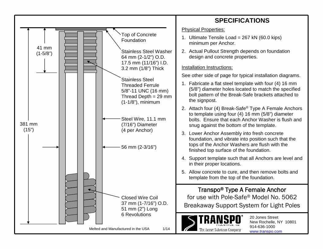
381 mm (15”)
Top of Concrete Foundation Stainless Steel Washer 64 mm (2-1/2”) O.D. 17.5 mm (11/16”) I.D. 3.2 mm (1/8”) Thick Stainless Steel Threaded Ferrule 5/8”-11 UNC (16 mm) Thread Depth = 29 mm (1-1/8”), minimum Steel Wire, 11.1 mm (7/16”) Diameter (4 per Anchor) 56 mm (2-3/16”) Closed Wire Coil 37 mm (1-7/16”) O.D. 51 mm (2”) Long 6 Revolutions
SPECIFICATIONS Physical Properties: 1. Ultimate Tensile Load = 267 kN (60.0 kips)
minimum per Anchor. 2. Actual Pullout Strength depends on foundation
design and concrete properties.
Installation Instructions: See other side of page for typical installation diagrams. 1. Fabricate a flat steel template with four (4) 16 mm
(5/8”) diameter holes located to match the specified bolt pattern of the Break-Safe brackets attached to the signpost.
2. Attach four (4) Break-Safe® Type A Female Anchors to template using four (4) 16 mm (5/8”) diameter bolts. Ensure that each Anchor Washer is flush and snug against the bottom of the template.
3. Lower Anchor Assembly into fresh concrete foundation, and vibrate into position such that the tops of the Anchor Washers are flush with the finished top surface of the foundation.
4. Support template such that all Anchors are level and in their proper locations.
5. Allow concrete to cure, and then remove bolts and template from the top of the foundation.
Transpo® Type A Female Anchor for use with Pole-Safe® Model No. 5062
Breakaway Support System for Light Poles
20 Jones Street New Rochelle, NY 10801 914-636-1000 www.transpo.com
41 mm (1-5/8”)
Melted and Manufactured in the USA 1/14
Transpo® Type A Female Anchor for use with Pole-Safe® Model No. 5062
Breakaway Support System for Light Poles 20 Jones Street New Rochelle, NY 10801 914-636-1000 www.transpo.com
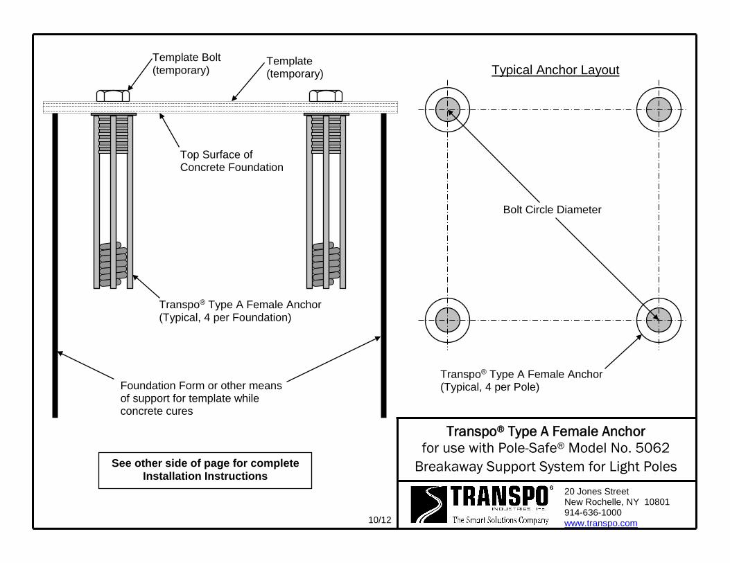
Transpo® Type A Female Anchor (Typical, 4 per Pole)
10/12
Bolt Circle Diameter
Top Surface of Concrete Foundation
Template (temporary)
Transpo® Type A Female Anchor (Typical, 4 per Foundation)
Foundation Form or other means of support for template while concrete cures
Template Bolt (temporary)
See other side of page for complete Installation Instructions
Typical Anchor Layout

25 mm (1”)
114 mm (4-1/2”)
57 mm (2-1/4”)
3/4”-10 UNC (19 mm) Nut per ASTM A563 Grade DH 3x21x36mm (1/8”x13/16”x1-7/16”) Flat Washer per ASTM F436 Pole Base Plate 3x21x36mm (1/8”x13/16”x1-7/16”) Flat Washer per ASTM F436 Upper Wrench Flats Double-NeckTM Pole-Safe® Coupling, Model No. 5075 4 per Pole, Typical Lower Wrench Flats Galvanized Steel Shim 14g and/or 18g Thickness (if required for leveling) Transpo® Type C Female Anchor, 3/4”-10 UNC (19 mm) Internal Threads (Anchors sold separately) Melted and Manufactured in the USA Patent Nos. 5,474,408 & 6,056,471 1/14
SPECIFICATIONS Performance Criteria:
1. Double-NeckTM Pole-Safe® conforms to AASHTO “Standard Specifications for Structural Supports for Highway Signs, Luminaires and Traffic Signals.”
2. Double-NeckTM Pole-Safe® has been crash-tested and FHWA approved in accordance with the requirements of NCHRP Report 350, “Recommended Procedures for the Safety Performance Evaluation of Highway Features.”
Physical Properties per Coupling:
1. Ultimate Tensile Strength = 131.0 kN (29.4 kips), minimum.
2. Tensile Yield Strength = 113.6 kN (25.5 kips), minimum.
3. Ultimate Restrained Shear Strength = 8.9 kN (2.0 kips), minimum.
4. Ultimate Restrained Shear Strength = 13.3 kN (3.0 kips), maximum.
Corrosion Protection:
1. All Double-NeckTM Pole-Safe® couplings, nuts, bolts, and washers are galvanized after fabrication in accordance with ASTM A153. All leveling shims are galvanized after fabrication in accordance with ASTM A653.
Pole-Safe® Model No. 5075 Breakaway Support System for Light Poles
20 Jones Street New Rochelle, NY 10801 914-636-1000 www.transpo.com

Pole-Safe® Model No. 5075 Breakaway Support System for Light Poles
INSTALLATION INSTRUCTIONS NOTE: Proper Installation is essential for the Pole-Safe Breakaway Support System to
function correctly as designed. Anchor Assembly: 1. Fasten Transpo® Type C Female Anchors to a rigid template pre-fabricated to match
the specified bolt circle. 2. Lower entire anchor assembly into the fresh concrete foundation, and vibrate
assembly into place, such that the anchors are in the proper location to match the holes in the pole base plate. Ensure that all anchors are level and that the tops of the individual anchors and the bottom of the template are flush with the finished top surface of the foundation.
3. Allow foundation to fully cure, and remove template from the anchors.
Coupling Assembly: 1. Surface of foundation around anchors must be smooth, flat and free of debris. 2. Thread Pole-Safe couplings into Transpo® Type C Female Anchors. 3. If needed, shims are provided for leveling of the pole base plate, and may be
installed at the base of the coupling(s). No more than 2 shims shall be installed on any one coupling. For larger adjustments that may be required, install no more than one additional flat washer under the base plate, on the top shank of the coupling(s).
4. Use lower wrench flats to tighten Pole-Safe couplings into the anchors. Secure couplings as tight as possible using conventional wrenches. Do not use a pipe wrench. Couplings must be seated squarely on top of the anchors.
5. Install a flat washer on top of each Pole-Safe coupling, and set the pole with base plate on top of the couplings.
6. Install a flat washer and nut on to each coupling extended through the pole base plate. If pole is not plumb, install shims and/or washers for proper leveling as described in Step 3 above.
7. Tighten each nut on to pole base plate. Pole-Safe couplings must be held with an additional wrench on the upper wrench flats to prevent an induced torque stress across the necked portion of the couplings. Nuts shall be tightened using the turn-of-nut method in accordance with American Institute of Steel Construction (AISC) procedures (1/3 rotation past “snug tight”).
Transpo Industries, Inc., 20 Jones Street, New Rochelle, NY 10801-6098
Phone: 914-636-1000 Fax: 914-636-1282 www.transpo.com
9/12
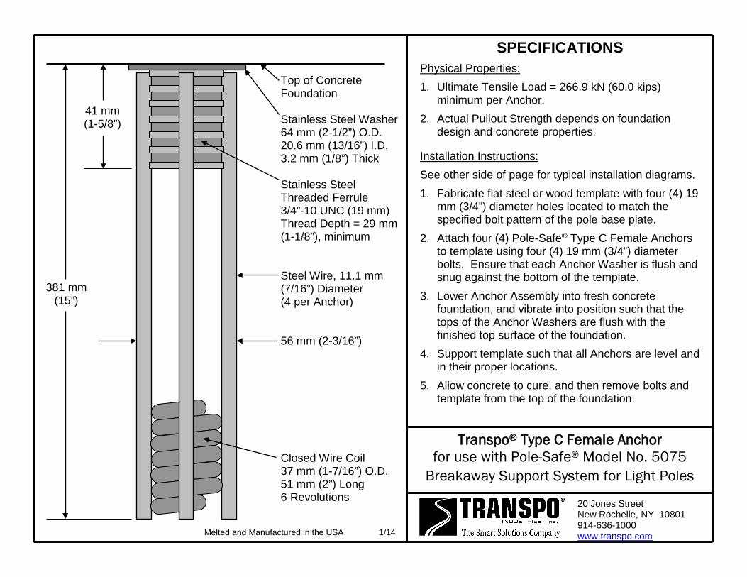
381 mm (15”)
Top of Concrete Foundation Stainless Steel Washer 64 mm (2-1/2”) O.D. 20.6 mm (13/16”) I.D. 3.2 mm (1/8”) Thick Stainless Steel Threaded Ferrule 3/4”-10 UNC (19 mm) Thread Depth = 29 mm (1-1/8”), minimum Steel Wire, 11.1 mm (7/16”) Diameter (4 per Anchor) 56 mm (2-3/16”) Closed Wire Coil 37 mm (1-7/16”) O.D. 51 mm (2”) Long 6 Revolutions
SPECIFICATIONS Physical Properties: 1. Ultimate Tensile Load = 266.9 kN (60.0 kips)
minimum per Anchor. 2. Actual Pullout Strength depends on foundation
design and concrete properties.
Installation Instructions: See other side of page for typical installation diagrams. 1. Fabricate flat steel or wood template with four (4) 19
mm (3/4”) diameter holes located to match the specified bolt pattern of the pole base plate.
2. Attach four (4) Pole-Safe® Type C Female Anchors to template using four (4) 19 mm (3/4”) diameter bolts. Ensure that each Anchor Washer is flush and snug against the bottom of the template.
3. Lower Anchor Assembly into fresh concrete foundation, and vibrate into position such that the tops of the Anchor Washers are flush with the finished top surface of the foundation.
4. Support template such that all Anchors are level and in their proper locations.
5. Allow concrete to cure, and then remove bolts and template from the top of the foundation.
Transpo® Type C Female Anchor for use with Pole-Safe® Model No. 5075
Breakaway Support System for Light Poles
20 Jones Street New Rochelle, NY 10801 914-636-1000 www.transpo.com
41 mm (1-5/8”)
Melted and Manufactured in the USA 1/14
Transpo® Type C Female Anchor for use with Pole-Safe® Model No. 5075
Breakaway Support System for Light Poles 20 Jones Street New Rochelle, NY 10801 914-636-1000 www.transpo.com
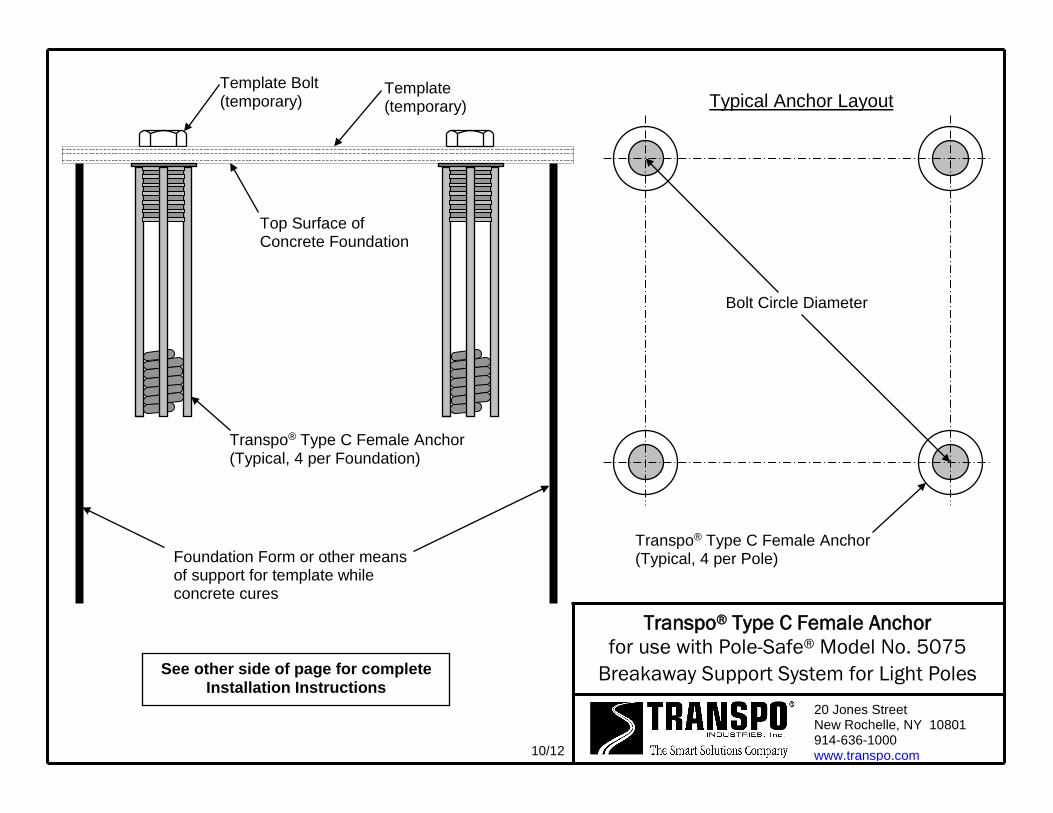
Transpo® Type C Female Anchor (Typical, 4 per Pole)
10/12
Bolt Circle Diameter
Top Surface of Concrete Foundation
Template (temporary)
Transpo® Type C Female Anchor (Typical, 4 per Foundation)
Foundation Form or other means of support for template while concrete cures
Template Bolt (temporary)
See other side of page for complete Installation Instructions
Typical Anchor Layout
29 mm (1-1/8”)
129 mm (5-1/16”)
70 mm (2-3/4”)
1”-8 UNC (25 mm) Nut per ASTM A563 Grade DH 3x28x51 mm (1/8”x1-1/8”x2”) Flat Washer per ASTM F436 Pole Base Plate 3x28x51 mm (1/8”x1-1/8”x2”) Flat Washer per ASTM F436 Upper Wrench Flats Double-NeckTM Pole-Safe® Coupling, Model No. 5100 4 per Pole, Typical Lower Wrench Flats Galvanized Steel Shim 14g and/or 18g Thickness (if required for leveling) Transpo® Type B Female Anchor, 1”-8 UNC (25 mm) Internal Threads (Anchors sold separately) Melted and Manufactured in the USA Patent Nos. 5,474,408 & 6,056,471 1/14
SPECIFICATIONS Performance Criteria:
1. Double-NeckTM Pole-Safe® conforms to AASHTO “Standard Specifications for Structural Supports for Highway Signs, Luminaires and Traffic Signals.”
2. Double-NeckTM Pole-Safe® has been crash-tested and FHWA approved in accordance with the requirements of NCHRP Report 350, “Recommended Procedures for the Safety Performance Evaluation of Highway Features.”
3. Maximum Allowable Pole Mass = 450 kg (992 lb) (total, including fixtures).
Physical Properties per Coupling:
1. Ultimate Tensile Strength = 221.5 kN (49.8 kips), minimum.
2. Tensile Yield Strength = 192.0 kN (43.2 kips), minimum.
3. Ultimate Restrained Shear Strength = 16.9 kN (3.8 kips), minimum.
4. Ultimate Restrained Shear Strength = 24.4 kN (5.5 kips), maximum.
Corrosion Protection:
1. All Double-NeckTM Pole-Safe® couplings, nuts, bolts, and washers are galvanized after fabrication in accordance with ASTM A153. All leveling shims are galvanized after fabrication in accordance with ASTM A653.
Pole-Safe® Model No. 5100 Breakaway Support System for Light Poles
20 Jones Street New Rochelle, NY 10801 914-636-1000 www.transpo.com

Pole-Safe® Model No. 5100 Breakaway Support System for Light Poles
INSTALLATION INSTRUCTIONS NOTE: Proper Installation is essential for the Pole-Safe Breakaway Support System to
function correctly as designed. Anchor Assembly: 1. Fasten Transpo® Type B Female Anchors to a rigid template pre-fabricated to match
the specified bolt circle. 2. Lower entire anchor assembly into the fresh concrete foundation, and vibrate
assembly into place, such that the anchors are in the proper location to match the holes in the pole base plate. Ensure that all anchors are level and that the tops of the individual anchors and the bottom of the template are flush with the finished top surface of the foundation.
3. Allow foundation to fully cure, and remove template from the anchors.
Coupling Assembly: 1. Surface of foundation around anchors must be smooth, flat and free of debris. 2. Thread Pole-Safe couplings into Transpo® Type B Female Anchors. 3. If needed, shims are provided for leveling of the pole base plate, and may be
installed at the base of the coupling(s). No more than 2 shims shall be installed on any one coupling. For larger adjustments that may be required, install no more than one additional flat washer under the base plate, on the top shank of the coupling(s).
4. Use lower wrench flats to tighten Pole-Safe couplings into the anchors. Secure couplings as tight as possible using conventional wrenches. Do not use a pipe wrench. Couplings must be seated squarely on top of the anchors.
5. Install a flat washer on top of each Pole-Safe coupling, and set the pole with base plate on top of the couplings.
6. Install a flat washer and nut on to each coupling extended through the pole base plate. If pole is not plumb, install shims and/or washers for proper leveling as described in Step 3 above.
7. Tighten each nut on to pole base plate. Pole-Safe couplings must be held with an additional wrench on the upper wrench flats to prevent an induced torque stress across the necked portion of the couplings. Nuts shall be tightened using the turn-of-nut method in accordance with American Institute of Steel Construction (AISC) procedures (1/3 rotation past “snug tight”).
Transpo Industries, Inc., 20 Jones Street, New Rochelle, NY 10801-6098
Phone: 914-636-1000 Fax: 914-636-1282 www.transpo.com
9/12

29 mm (1-1/8”)
136 mm (5-3/8”)
83 mm (3-1/4”)
1-1/4”-7 UNC (32 mm) Nut per ASTM A563 Grade DH 3x35x63mm(1/8”x1-3/8”x2-1/2”) Flat Washer per ASTM F436 Pole Base Plate 3x35x63mm(1/8”x1-3/8”x2-1/2”) Flat Washer per ASTM F436 Upper Wrench Flats Double-NeckTM Pole-Safe® Coupling, Model No. 5125 4 per Pole, Typical Lower Wrench Flats 1”-8 UNC Thread-2A Galvanized Steel Shim 14g and/or 18g Thickness (if required for leveling) Transpo® Type B Female Anchor, 1”-8 UNC (25 mm) Internal Threads (Anchors sold separately) Melted and Manufactured in the USA Patent Nos. 5,474,408 & 6,056,471 1/14
SPECIFICATIONS Performance Criteria:
1. Double-NeckTM Pole-Safe® conforms to AASHTO “Standard Specifications for Structural Supports for Highway Signs, Luminaires and Traffic Signals.”
2. Double-NeckTM Pole-Safe® has been crash-tested and FHWA approved in accordance with the requirements of NCHRP Report 350, “Recommended Procedures for the Safety Performance Evaluation of Highway Features.”
3. Maximum Allowable Pole Mass = 450 kg (992 lb.) (total, including fixtures).
Physical Properties per Coupling:
1. Ultimate Tensile Strength = 221.5 kN (49.8 kips), minimum.
2. Tensile Yield Strength = 192.0 kN (43.2 kips), minimum.
3. Ultimate Restrained Shear Strength = 16.9 kN (3.8 kips), minimum.
4. Ultimate Restrained Shear Strength = 24.4 kN (5.5 kips), maximum.
Corrosion Protection:
1. All Double-NeckTM Pole-Safe® couplings, nuts, bolts, and washers are galvanized after fabrication in accordance with ASTM A153. All leveling shims are galvanized after fabrication in accordance with ASTM A653.
Pole-Safe® Model No. 5125 Breakaway Support System for Light Poles
20 Jones Street New Rochelle, NY 10801 914-636-1000 www.transpo.com

Pole-Safe® Model No. 5125 Breakaway Support System for Light Poles
INSTALLATION INSTRUCTIONS NOTE: Proper Installation is essential for the Pole-Safe Breakaway Support System to
function correctly as designed. Anchor Assembly: 1. Fasten Transpo® Type B Female Anchors to a rigid template pre-fabricated to match
the specified bolt circle. 2. Lower entire anchor assembly into the fresh concrete foundation, and vibrate
assembly into place, such that the anchors are in the proper location to match the holes in the pole base plate. Ensure that all anchors are level and that the tops of the individual anchors and the bottom of the template are flush with the finished top surface of the foundation.
3. Allow foundation to fully cure, and remove template from the anchors.
Coupling Assembly: 1. Surface of foundation around anchors must be smooth, flat and free of debris. 2. Thread Pole-Safe couplings into Transpo® Type B Female Anchors. 3. If needed, shims are provided for leveling of the pole base plate, and may be
installed at the base of the coupling(s). No more than 2 shims shall be installed on any one coupling. For larger adjustments that may be required, install no more than one additional flat washer under the base plate, on the top shank of the coupling(s).
4. Use lower wrench flats to tighten Pole-Safe couplings into the anchors. Secure couplings as tight as possible using conventional wrenches. Do not use a pipe wrench. Couplings must be seated squarely on top of the anchors.
5. Install a flat washer on top of each Pole-Safe coupling, and set the pole with base plate on top of the couplings.
6. Install a flat washer and nut on to each coupling extended through the pole base plate. If pole is not plumb, install shims and/or washers for proper leveling as described in Step 3 above.
7. Tighten each nut on to pole base plate. Pole-Safe couplings must be held with an additional wrench on the upper wrench flats to prevent an induced torque stress across the necked portion of the couplings. Nuts shall be tightened using the turn-of-nut method in accordance with American Institute of Steel Construction (AISC) procedures (1/3 rotation past “snug tight”).
Transpo Industries, Inc., 20 Jones Street, New Rochelle, NY 10801-6098
Phone: 914-636-1000 Fax: 914-636-1282 www.transpo.com
9/12

381 mm (15”)
Top of Concrete Foundation Stainless Steel Washer 64 mm (2-1/2”) O.D. 27 mm (1-1/16”) I.D. 3.2 mm (1/8”) Thick Stainless Steel Threaded Ferrule 1”-8 UNC (25 mm) Thread Depth = 29 mm (1-1/8”), minimum Steel Wire, 11.1 mm (7/16”) Diameter (4 per Anchor) 56 mm (2-3/16”) Closed Wire Coil 37 mm (1-7/16”) O.D. 51 mm (2”) Long 6 Revolutions
SPECIFICATIONS Physical Properties: 1. Ultimate Tensile Load = 267 kN (60.0 kips)
minimum per Anchor. 2. Actual Pullout Strength depends on foundation
design and concrete properties.
Installation Instructions: See other side of page for typical installation diagrams. 1. Fabricate flat steel or wood template with four (4) 25
mm (1”) diameter holes located to match the specified bolt pattern of the Break-Safe brackets attached to the signpost.
2. Attach four (4) Break-Safe® Type B Female Anchors to template using four (4) 25 mm (1”) diameter bolts. Ensure that each Anchor Washer is flush and snug against the bottom of the template.
3. Lower Anchor Assembly into fresh concrete foundation, and vibrate into position such that the tops of the Anchor Washers are flush with the finished top surface of the foundation.
4. Support template such that all Anchors are level and in their proper locations.
5. Allow concrete to cure, and then remove bolts and template from the top of the foundation.
Transpo® Type B Female Anchor for use with Pole Safe® Model No. 5100 and 5125
Breakaway Support System for Light Poles
20 Jones Street New Rochelle, NY 10801 914-636-1000 www.transpo.com
41 mm (1-5/8”)
Melted and Manufactured in the USA 1/14

Transpo® Type B Female Anchor for use with Pole-Safe® Model No. 5100 and 5125
Breakaway Support System for Light Poles
20 Jones Street New Rochelle, NY 10801 914-636-1000 www.transpo.com
Transpo® Type B Female Anchor (Typical, 4 per Pole)
10/12
Bolt Circle Diameter
Top Surface of Concrete Foundation
Template (temporary)
Transpo® Type B Female Anchor (Typical, 4 per Foundation)
Foundation Form or other means of support for template while concrete cures
Template Bolt (temporary)
See other side of page for complete Installation Instructions
Typical Anchor Layout

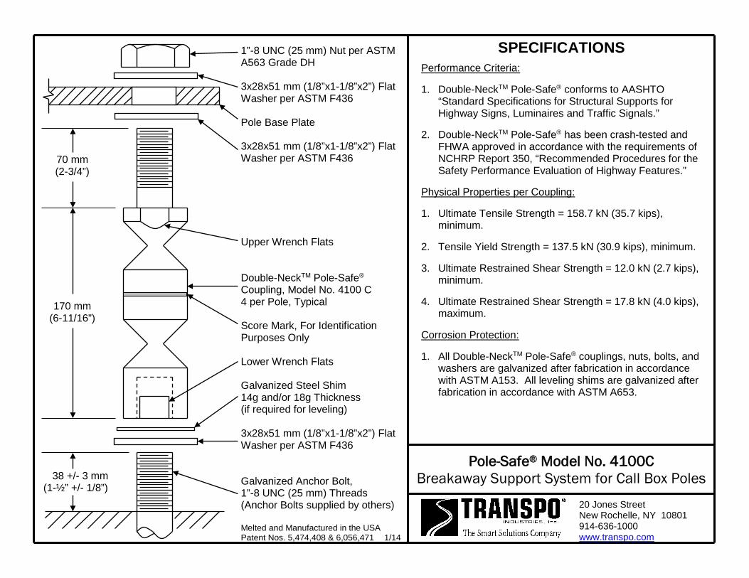
38 +/- 3 mm (1-½” +/- 1/8”)
170 mm (6-11/16”)
70 mm (2-3/4”)
1”-8 UNC (25 mm) Nut per ASTM A563 Grade DH 3x28x51 mm (1/8”x1-1/8”x2”) Flat Washer per ASTM F436 Pole Base Plate 3x28x51 mm (1/8”x1-1/8”x2”) Flat Washer per ASTM F436 Upper Wrench Flats Double-NeckTM Pole-Safe® Coupling, Model No. 4100 C 4 per Pole, Typical Score Mark, For Identification Purposes Only Lower Wrench Flats Galvanized Steel Shim 14g and/or 18g Thickness (if required for leveling) 3x28x51 mm (1/8”x1-1/8”x2”) Flat Washer per ASTM F436 Galvanized Anchor Bolt, 1”-8 UNC (25 mm) Threads (Anchor Bolts supplied by others) Melted and Manufactured in the USA Patent Nos. 5,474,408 & 6,056,471 1/14
SPECIFICATIONS Performance Criteria:
1. Double-NeckTM Pole-Safe® conforms to AASHTO “Standard Specifications for Structural Supports for Highway Signs, Luminaires and Traffic Signals.”
2. Double-NeckTM Pole-Safe® has been crash-tested and FHWA approved in accordance with the requirements of NCHRP Report 350, “Recommended Procedures for the Safety Performance Evaluation of Highway Features.”
Physical Properties per Coupling:
1. Ultimate Tensile Strength = 158.7 kN (35.7 kips), minimum.
2. Tensile Yield Strength = 137.5 kN (30.9 kips), minimum.
3. Ultimate Restrained Shear Strength = 12.0 kN (2.7 kips), minimum.
4. Ultimate Restrained Shear Strength = 17.8 kN (4.0 kips), maximum.
Corrosion Protection:
1. All Double-NeckTM Pole-Safe® couplings, nuts, bolts, and washers are galvanized after fabrication in accordance with ASTM A153. All leveling shims are galvanized after fabrication in accordance with ASTM A653.
Pole-Safe® Model No. 4100C Breakaway Support System for Call Box Poles
20 Jones Street New Rochelle, NY 10801 914-636-1000 www.transpo.com

Pole-Safe® Model No. 4100C Breakaway Support System for Call Box Poles
INSTALLATION INSTRUCTIONS
NOTE: Proper Installation is essential for the Pole-Safe Breakaway Support System to
function correctly as designed. 1. Surface of foundation around anchor bolts must be smooth, flat and free of debris.
2. Existing anchor bolts MUST be sized to the proper projection height as shown on the reverse side of these instructions. Then, anchor bolts shall be cleaned, and if necessary, coated with cold galvanizing material prior to installing Pole-Safe couplings.
3. Install lower flat washers, and thread Pole-Safe couplings on to anchor bolts.
4. If needed, shims are provided for leveling of the pole base plate, and may be installed at the base of the coupling(s). No more than 2 shims shall be installed on any one coupling. For larger adjustments that may be required, install no more than one additional flat washer under the base plate, on the top shank of the coupling(s).
5. Use lower wrench flats to tighten Pole-Safe couplings on to the anchor bolts. Secure couplings as tight as possible using conventional wrenches. Do not use a pipe wrench. Couplings must be seated squarely on the washers, and washers must be seated uniformly on top of the foundation. If necessary, remove coupling and reduce the anchor bolt projection height to allow proper seating of the couplings.
6. Install a flat washer on top of each Pole-Safe coupling, and set the pole with base plate on top of the couplings.
7. Install a flat washer and nut on to each Pole-Safe coupling extended through the pole base plate. If pole is not plumb, install shims and/or washers for proper leveling as described in Step 4 above.
8. Tighten each nut on to pole base plate. Pole-Safe couplings must be held with an additional wrench on the upper wrench flats to prevent an induced torque stress across the necked portion of the couplings. Nuts shall be tightened using the turn-of-nut method in accordance with American Institute of Steel Construction (AISC) procedures (for ASTM A325 and A490 anchor bolts, 1/3 rotation past “snug tight”).
Transpo Industries, Inc., 20 Jones Street, New Rochelle, NY 10801-6098
Phone: 914-636-1000 Fax: 914-636-1282 www.transpo.com
10/12
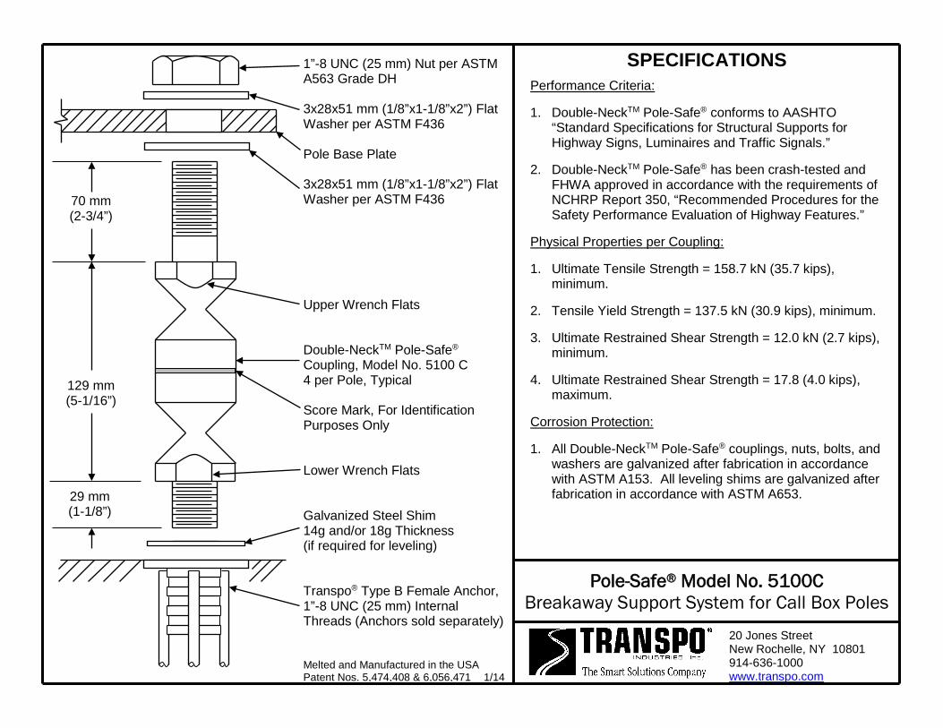
29 mm (1-1/8”)
129 mm (5-1/16”)
70 mm (2-3/4”)
1”-8 UNC (25 mm) Nut per ASTM A563 Grade DH 3x28x51 mm (1/8”x1-1/8”x2”) Flat Washer per ASTM F436 Pole Base Plate 3x28x51 mm (1/8”x1-1/8”x2”) Flat Washer per ASTM F436 Upper Wrench Flats Double-NeckTM Pole-Safe® Coupling, Model No. 5100 C 4 per Pole, Typical Score Mark, For Identification Purposes Only Lower Wrench Flats Galvanized Steel Shim 14g and/or 18g Thickness (if required for leveling) Transpo® Type B Female Anchor, 1”-8 UNC (25 mm) Internal Threads (Anchors sold separately) Melted and Manufactured in the USA Patent Nos. 5,474,408 & 6,056,471 1/14
SPECIFICATIONS Performance Criteria:
1. Double-NeckTM Pole-Safe® conforms to AASHTO “Standard Specifications for Structural Supports for Highway Signs, Luminaires and Traffic Signals.”
2. Double-NeckTM Pole-Safe® has been crash-tested and FHWA approved in accordance with the requirements of NCHRP Report 350, “Recommended Procedures for the Safety Performance Evaluation of Highway Features.”
Physical Properties per Coupling:
1. Ultimate Tensile Strength = 158.7 kN (35.7 kips), minimum.
2. Tensile Yield Strength = 137.5 kN (30.9 kips), minimum.
3. Ultimate Restrained Shear Strength = 12.0 kN (2.7 kips), minimum.
4. Ultimate Restrained Shear Strength = 17.8 (4.0 kips), maximum.
Corrosion Protection:
1. All Double-NeckTM Pole-Safe® couplings, nuts, bolts, and washers are galvanized after fabrication in accordance with ASTM A153. All leveling shims are galvanized after fabrication in accordance with ASTM A653.
Pole-Safe® Model No. 5100C Breakaway Support System for Call Box Poles
20 Jones Street New Rochelle, NY 10801 914-636-1000 www.transpo.com

Pole-Safe® Model No. 5100C Breakaway Support System for Call Box Poles
INSTALLATION INSTRUCTIONS NOTE: Proper Installation is essential for the Pole-Safe Breakaway Support System to
function correctly as designed. Anchor Assembly: 1. Fasten Transpo® Type B Female Anchors to a rigid template pre-fabricated to match
the specified bolt circle. 2. Lower entire anchor assembly into the fresh concrete foundation, and vibrate
assembly into place, such that the anchors are in the proper location to match the holes in the pole base plate. Ensure that all anchors are level and that the tops of the individual anchors and the bottom of the template are flush with the finished top surface of the foundation.
3. Allow foundation to fully cure, and remove template from the anchors.
Coupling Assembly: 1. Surface of foundation around anchors must be smooth, flat and free of debris. 2. Thread Pole-Safe couplings into Transpo® Type B Female Anchors. 3. If needed, shims are provided for leveling of the pole base plate, and may be
installed at the base of the coupling(s). No more than 2 shims shall be installed on any one coupling. For larger adjustments that may be required, install no more than one additional flat washer under the base plate, on the top shank of the coupling(s).
4. Use lower wrench flats to tighten Pole-Safe couplings into the anchors. Secure couplings as tight as possible using conventional wrenches. Do not use a pipe wrench. Couplings must be seated squarely on top of the anchors.
5. Install a flat washer on top of each Pole-Safe coupling, and set the pole with base plate on top of the couplings.
6. Install a flat washer and nut on to each coupling extended through the pole base plate. If pole is not plumb, install shims and/or washers for proper leveling as described in Step 3 above.
7. Tighten each nut on to pole base plate. Pole-Safe couplings must be held with an additional wrench on the upper wrench flats to prevent an induced torque stress across the necked portion of the couplings. Nuts shall be tightened using the turn-of-nut method in accordance with American Institute of Steel Construction (AISC) procedures (1/3 rotation past “snug tight”).
Transpo Industries, Inc., 20 Jones Street, New Rochelle, NY 10801-6098
Phone: 914-636-1000 Fax: 914-636-1282 www.transpo.com
9/12
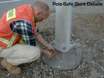
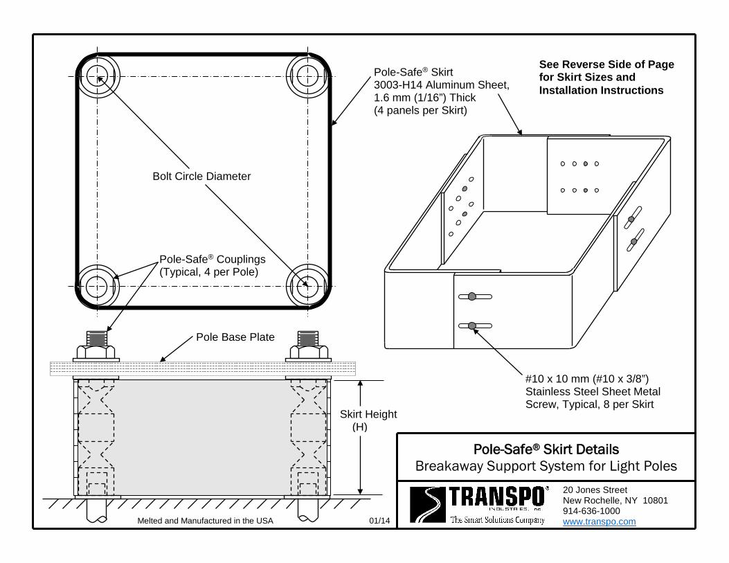
Pole-Safe® Skirt Details Breakaway Support System for Light Poles
20 Jones Street New Rochelle, NY 10801 914-636-1000 www.transpo.com
See Reverse Side of Page for Skirt Sizes and Installation Instructions
Bolt Circle Diameter
Pole-Safe® Couplings (Typical, 4 per Pole)
Pole-Safe® Skirt 3003-H14 Aluminum Sheet, 1.6 mm (1/16”) Thick (4 panels per Skirt)
#10 x 10 mm (#10 x 3/8”) Stainless Steel Sheet Metal Screw, Typical, 8 per Skirt
Pole Base Plate
Skirt Height (H)
01/14 Melted and Manufactured in the USA

Pole-Safe® Breakaway Support System for Light Poles
SKIRT INFORMATION Selection Table:
Pole-Safe® Model No.
Bolt Circle Diameter
Skirt Height
(H) mm (in.)
254 mm to 380 mm 380 mm to 500 mm (10” to 15”) (15” to 20”)
Skirt Part No.
Skirt Part No.
4062 SPMKDN-4 SPMKDN-4L 146 (5-3/4) 4075 SPMKDN-4 SPMKDN-4L 146 (5-3/4) 4100 SPMKDN-5 SPMKDN-5L 168 (6-5/8) 4125 SPMKDN-5 SPMKDN-5L 168 (6-5/8)
5062 SPMKDN-1 SPMKDN-1L 108 (4-1/4) 5075 SPMKDN-1 SPMKDN-1L 108 (4-1/4) 5100 SPMKDN-2 SPMKDN-2L 127 (5) 5125 SPMKDN-3 SPMKDN-3L 133 (5-1/4)
Installation Instructions:
1. Place 4 skirt panels around Pole-Safe Couplings using overlap configuration shown on reverse side of page. All 4 sides of the skirt box should have 2 slots facing outside.
2. Thread 8 sheet metal screws through the outside slots into the closest corresponding holes in the adjacent inside panel.
3. Position panels snug against the Pole-Safe Couplings.
4. Tighten all 8 sheet metal screws.
Transpo Industries, Inc., 20 Jones Street, New Rochelle, NY 10801-6098 Phone: 914-636-1000 Fax: 914-636-1282
www.transpo.com 6/00