polarization
DESCRIPTION
polarizacionTRANSCRIPT
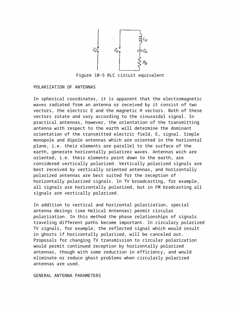
Figure 10-5 RLC circuit equivalent
POLARIZATION OF ANTENNAS
In spherical coordinates, it is apparent that the electromagnetic waves radiated from an antenna or received by it consist of two vectors, the electric E and the magnetic H vectors. Both of these vectors rotate and vary according to the sinusoidal signal. In practical antennas, however, the orientation of the transmitting antenna with respect to the earth will determine the dominant orientation of the transmitted electric field, E, signal. Simple monopole and dipole antennas which are oriented in the horizontal plane, i.e. their elements are parallel to the surface of the earth, generate horizontally polarirez waves. Antennas wich are oriented, i.e. their elements point down to the earth, are considered vertically polarized. Vertically polarized signals are best received by vertically oriented antennas, and horizontally polarized antennas are best suited for the reception of horizontally polarized signals. In TV broadcasting, for example, all signals are horizontally polarized, but in FM bradcasting all signals are vertically polarized.
In addition to vertical and horizontal polarization, special antenna desings (see Helical Antennas) permit circular polarization. In this method the phase relationships of signals traveling different paths become important. In circulary polarized TV signals, for example, the reflected signal which would result in ghosts if horizontally polarized, will be canceled out. Proposals for changing TV transmission to circular polarization would permit continued reception by horizontally polarized antennas, though with some reduction in efficiency, and would eliminate or reduce ghost problems when circularly polarized antennas are used.
GENERAL ANTENNA PARAMETERS
While many of the general parameters are specifically derived for halfwave, center-fed, dipole antennas, they apply equally well to all types of antennas and from the basic concepts for more detailed and practical calculations.
(a) Near and far fields: The electromagnetic field in the immediate vicinity of an antenna is usually called the “near field” and includes induction (magnetic) as well as electrical field and radiation field considerations. Evaluation of these effects is essential when antennas are located close to each other or to other objects and the mutual effects must be determined. Near field effects are of primary importance in the desing of antenna configurations and arrays, as described in section 10.3. the far or radation field is considered to start at least five wave lengths away from the antenna and is used in the reception and transmission calculations of communications systems. Unless the “near field” is specifically mentioned, all antenna formulas aplly to the far field only.
(b) Antenna gain: Although the term antenna gain is loosely applied to both the power gain Gp and the directive gain Gd, it is often important to make the distinction. The directive gain is a function of the radiation intensity which is defined as the power per unit solid angle in that direction and the total power radiates as indicates below.
Gd=❑W r
;W r = power radiated, in watts
Directive gain is also often called directivity D, which is defined as the maximum directive gain.
The power gain is given by the formula below:
G p=4 πW z
;W z= total power input, in watts
The ratio of power gain and directive gain provides an indication of the efficiency of the antenna, since the power loss of the antenna is included in this term. For a half-wave dipole antenna, D=1.64=2.15 db.
(c) Effective area (aperture): Not all of the antenna area is always utilized to radiate properly polarized signals nor is there a 100% efficient and correcct impedance match between the antenna and the transmitter or receiver. The effective area of antenna is given by the following formula:
Ae=❑2
4 πGd ; = wave length
(d) End effect: the plates of a capacitor do not provide the exact capacity indicated by geometry because the ends of the plates are no longer completely opposed by the other plates. For similar reasons, there are ends effects in antennas. The magnitude of these effects depends on the ratio of length to diameter of cylindrical antennas and to other objects (in the near field). The end effect results in apparent lengthening of the antenna dimensios, meaning that they will be longer, beyond the resonance point. In practical applications, a 5% shortening of the mecanical antenna dimensions results in the most accurate electrical length.
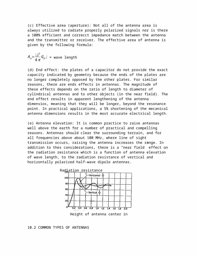
(e) Antenna elevation: It is common practice to raise antennas well above the earth for a number of practical and compelling reasons. Antennas should clear the surrounding terrain, and for all frequencies above about 100 MHz, where line of sight transmission occurs, raising the antenna increases the range. In addition to thes considerations, there is a “near field” effect on the radiation resistance which is a function of antenna elevation of wave length, to the radiation resistance of vertical and horizontally polarized half-wave dipole antennas.
10.2 COMMON TYPES OF ANTENNAS
MONOPOLE ANTENNASAny simple wire, connected to a source of RF, acts as a monopole antenna in that it radiates energy. One type of monopole antenna is the vertical “whip” antenna used for automobile radios. This type of antenna is considerably smaller than a quarter wave length and depends on the proximity of the ground plane for its operation. The impedance and radiation characteristics
Height of antenna center in wavelengths
Radiation resistance (ohms)