point beach - procedure it 300b, rev. 10, s/g 'b' mf line
TRANSCRIPT
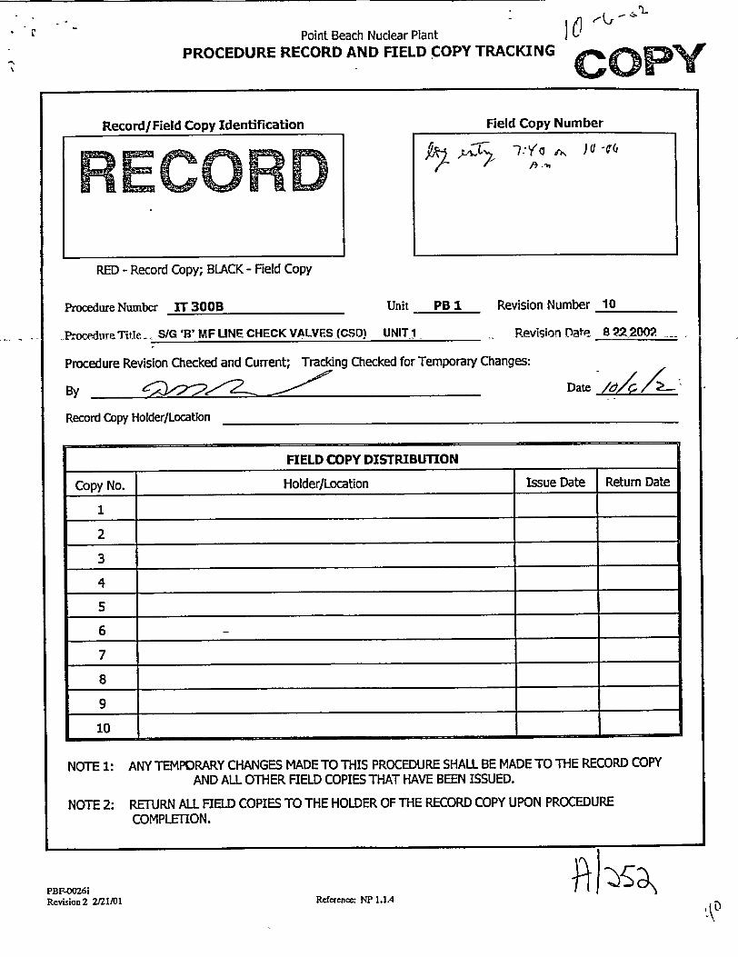
"Point Beach Nuclear Plant
PROCEDURE RECORD AND FIELD COPY TRACKINGc
Record/Field Copy Identification AVECOkRDI RM Field Copy Number
TY'o~)UV
RED - Record Copy; BLACK - Field Copy
Procedure Number IT 300B
oPr.oce-ure7 Title . S/G 'B' MF UNE CHECK VALVES (CSD)
Unit PBUI
UNIT 1
Revision Number 10
Revision Date 8 9_2200"2
Procedure Revision Checked and Current; Tracking Checked for Temporary Changes:
By V 22~Record Copy Holder/Location
FIELD COPY DISTRIBUTION
Copy No. Holder/Location Issue Date Return Date
1
2
3
4
5
6
7
8
9
10
NOTE 1: ANY TEMPORARY CHANGES MADE TO THIS PROCEDURE SHALL BE MADE TO THE RECORD COPY AND ALL OTHER FIELD COPIES THAT HAVE BEEN ISSUED.
NOTE 2: RETURN ALL FIELD COPIES TO THE HOLDER OF THE RECORD COPY UPON PROCEDURE COMPLETION.
PBF-.026i Revision 2 2/21/01 Reference: NP 1.1.4 'A0
Date
IT 300B
STEAM GENERATOR B MAIN FEED LINE CHECK VALVES
(COLD SHUTDOWN) UNIT 1
DOCUMENT TYPE:
CLASSIFICATION:
REVISION:
EFFECTIVE DATE:
REVIEWER:
APPROVAL AUTHORITY:
PROCEDURE OWNER (title):
OWNER GROUP:
Verified Current Copy:
t
List pages used for Partial Performance
Technical
Safety Related
10
August 22, 2002
Qualified Reviewer
Department Manager
Group Head
Operations
Signature Date Time
Controlling Work Document Numbers 9ýYY 7z-5_
- - ý 1 .1
POINT BEACH NUCLEAR PLANT IT 300B E NSERVICE TESTS SAFETY RELATED
Revision 10 STEAM GENERATOR B MAIN FEED LINE CHECK August 22, 2002 VALVES (COLD SHUTDOWN) UNIT I
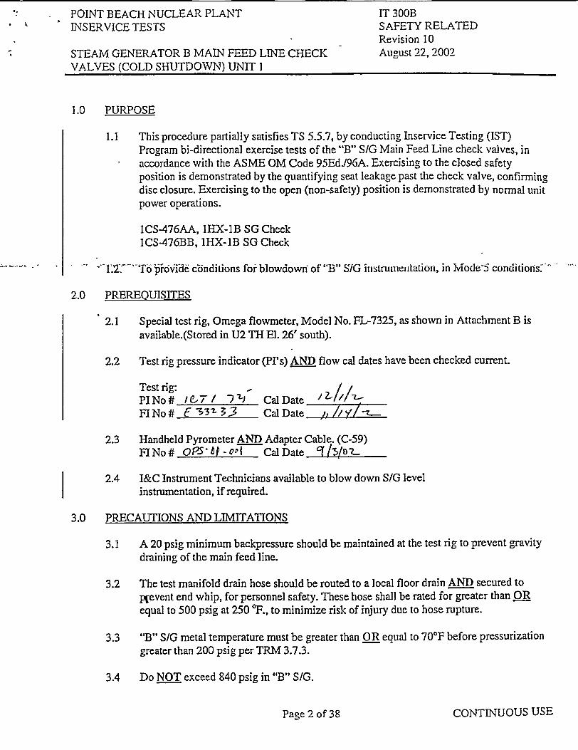
1.0 PURPOSE
1.1 This procedure partially satisfies TS 5.5.7, by conducting Inservice Testing (IST) Program bi-directional exercise tests of the "B" S/G Main Feed Line check valves, in accordance with the ASME OM Code 95EdJ96A. Exercising to the closed safety position is demonstrated by the quantifying seat leakage past the check valve, confirming disc closure. Exercising to the open (non-safety) position is demonstrated by normal unit power operations.
1CS-476AA, IHX-IB SG Check 1CS-476BB, 1HX-1B SG Check
"•"-o.2-To p56id crnditions for blowdown" of "B" SIG instrumentation, in Mode'5 conditioris.
2.0 PREREQUISITES
2.1 Special test rig, Omega flowmeter, Model No. FL-7325, as shown in Attachment B is available.(Stored in U2 TH El. 26' south).
2.2 Test rig pressure indicator (PI's) AND flow cal dates have been checked current.
Test rig: - // PI No .7 / e, 7 Cal Date FINo# 3 -3z CalDate /iI-z_
2.3 Handheld Pyrometer AND Adapter Cable. (C-59) FINo# OPS-AP¢-odI CalDate 41s0 7..
2.4 I&C Instrument Technicians available to blow down S/G level
instrumentation, if required.
3.0 PRECAUTIONS AND LIMITATIONS
3.1 A 20 psig minimum backpressure should be maintained at the test rig to prevent gravity draining of the main feed line.
3.2 The test manifold drain hose should be routed to a local floor drain AND secured to p(event end whip, for personnel safety. These hose shall be rated for greater than OR equal to 500 psig at 250 TF., to minimize risk of injury due to hose rupture.
3.3 "B" S/G metal temperature must be greater than OR equal to 70'F before pressurization greater than 200 psig per TRM 3.7.3.
3.4 Do NOT exceed 840 psig in "B" S/G.
CONTINUOUS USEPage 2 of 38

POINT BEACH NUCLEAR PLANT INSERVICE TESTS
STEAM GENERATOR B MALN FEED LINE CHECK VALVES (COLD SHUTDOWN) UNIT I
IT 360B SAFETY RELATED Revision 10 August 22, 2002
3.5 Do NOT OPEN IMS-2015, IHX-1B SG Hdr Atmospheric Steam Dump Control, when steam lines are filled except to avoid exceeding 840 psig.
3.6 Do NOT use, IMS-2015, 1HX-IB SG Hdr Atmospheric Steam Dump Control, as a vent path while filling "B" S/G.
CONTINUOUS USEPagre 3 of 38

POINT BEACH NUCLEAR PLANT INSERVICE TESTS
STEAM GENERATOR B MAIN FEED LINE CHECK VALVES (COLD SHUTDOWN) UNIT I
IT 300B SAFETY RELATED Revision 10 August 22, 2002
INITIALS
4.0 INITIAL CONDITIONS
4.1 This test is being done to satisfy:
_ _ The normally scheduled callup. Work Order No. 043q'S"77
NOTE: If this test is being performed to satisfy PMT or off-normal frequency requirements, Shift Management may N/A those portions of the procedure that are NOT applicable for the performance of the PMT. The use of N/A is NOT acceptable for Initial Conditions, Precautions and Limitations, or procedure
. ste'ps thit P&.tini o the e4uijmiiuit r'equirihg PMT, h30is If acceptable for restoration of equipment/components unless the component has been declared inoperable.
Post-maintenance operability test for: Equipment IDWO No(s). Special test - no numbers Explain:
4.2 01150, Heating the Condensate Storage Tanks, has been implemented to split CST's AND heat T-24A, South CST to 80-1 10°F.
4.3 At least 1 "B" S/G main steam safety valve must be operable. (Circle operable IHX-1B SG Header Safety valves).
"* IMS-2005
"* 1MS-2006
"* IMS-2007
"* 1MS-2008
4.4 Any safety valve removed must have full pressure blank flange installed.
4.5 "B" S/G hand hole covers installed.
4.6 "B" S/G secondary manways installed.
#1�
2•22zz
MTN
MTN
MTN
CONTINUOUS USEPage 4 of 38

POINT BEACH NUCLEAR PLANT INSERVICE TESTS
STEAM GENERATOR B MAIN FEED LINE CHECK VALVES (COLD SHUTDOWN) UNIT I
IT 300B SAFETY RELATED Revision 10 August 22, 2002
4.7 "B" SIG feed line intact FROM main and bypass feedwater reg. valves inlet isolation TO "B" SIG.
4.8 All "B" SfG tubes that require plugging are plugged on BOTH ends. (N/A if primary manways are installed)
11K
MTN
ISI
4.9 Chemistry notified
* To determine discharge permit requirements to utilize steam generator blowdown system.
o. To determine chemical .qddition requirements AND to have required chemicals available at P-38B Chemical Addition Pot.
4.10 Unit I in MODE 5,6, ORDefueled.
4.11 "B" SIG Wide Range Level, LT-470A OR LT-470B, operable.
4.12 PBF-2051, "B" S/Blowdown Flow Rate Log Sheet, is available if required.
4.13 P-38B, Aux Feedwater Motor-Driven Pump AND flow path to "B" S/G is available with no outstanding clearances OR associated work is in progress.
4.14 "B" SIG Blowdown system has no outstanding clearances, no associated work in progress AND is available to receive drains from steam line B AND "B" SIG blowdown.
4.15 Permission to Perform Test
I&C
WCC
WCc
The conditions required by this test are consistent with required plant conditions incluA g equipment operability. Permission is granted to perfr this ta',
DZK' Z4 /f A -Time ( L• Date
CONTINUOUS USE
INITIALS
I
Page 5 of 38

POINT BEACH NUCLEAR PLANT IT 300B INSERVICE TESTS SAFETY RELATED
Revision 10 STEAM GENERATOR B MAIN FEED LINE CHECK August 22, 2002 VALVES (COLD SHUTDOWN) UNIT I
INITIALS
5.0 PROCEDURE
5.1 PT-478, IHX-IB Steam Pressure Channel in service.
5.1.1 IMS-478, 1HX-1B SG Header PT-478 Root. OPEN Z
5.1.2 1MS-478A, IHX-1B SG Header PT-478 2nd Off Isolation. OPENS
5.1.3 PT-478, 1HX-1B Steam Pressure Channel. OPERABLE..___,,____ _-. I&C
5.2 Ensure one OR both SG Steam Pressure Channels in service PT-479 OR *...... PT.483 (Mark unused channel as N/A). _ .
5.2.1 IMS-479, 1HX-1B SG Header PT-479 Root OPEN
5.2.2 1MS-479A, IHX-1B SG Header PT-479 2nd Off Isolation. OPEN q'
5.2.3 PT-479, 1HX-1B Steam Pressure Channel. OPERABLE F J /2--T9 I&C
OR
5.2.4 IMS-483, 1HX-1B SG Header PT-483 Root. OPEN (_ _
5.2.5 1MS-483A, IHX-IB SG Header PT-483 2nd Off Isolation OPEN_(4
5.2.6 PT-483, 1HX-1B Steam Pressure Channel. OPERABLE )L-/FVZJ!/ I&C
5.3 IF feed line has been drained since shutdown, THEN perform Main Feed Line fill per Attachment A, step 1.0. 4,i •
CONTINUOUS USEPage 6 of 38

POINT BEACH NUCLEAR PLANT INSERVICE TESTS
STEAM GENERATOR B MAIN FEED LINE CHECK VALVES (COLD SHUTDOWN) UNIT I
IT 300B SAFETY RELATED Revision 10 August 22, 2002
INITIALS
5.4 Obtain "B" S/G metal temperatures by performing steps 5.4.1 OR 5.4.2. (N/A the one NOT used)
5.4.1 Using hand held pyrometer AND adapter cable located at C-59, plug adapter cable into thermocouple junction box located on "B" S/G missile shield wall AND record readings:
a. TE-2022A, lHX-1B SG Shell Temperature Thermocouple
Above feedwater inlet _-__ -F
. ....... b. ..,TE-2022U, 1HX-1B SG Shell Tcn.--eratue Tl'e:riocoup1&; Below transition cone 1.. -F
c. TE-2022C, 1HX-IB SG Shell Temperature Thermocouple Above tubesheet -CU. -F
Using hand held pyrometer, obtain metal temperatures at "B" SIG upper manway Oi upper level tap penetration.
5.5 IF "B" SIG temperatures less than 700F, THEN establish "B" S/G level less than OR equal to 360 inches.
5.6 WHEN "B" S/G pressurized greater than 50 psig but less than OR equal to 100 psig, THEN arrange with I&C to blow down "B" SIG level transmitters, if required.
2
CONTINUOUS USE
5.4.2
Pace 7 of 38
POINT BEACH NUCLEAR PLANT INSERVICE TESTS
STEAM GENERATOR B MAIN FEED LINE CHECK VALVES (COLD SHUTDOWN) UNIT I
IT 300B SAFETY RELATED Revision 10 August 22, 2002
CONTINUOUS USE
. i
INITIALS
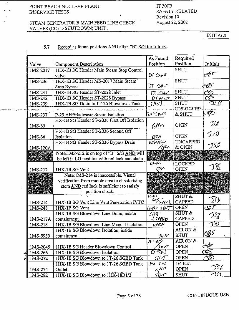
5.7 Record as found positions AND align "B" S/G for filling:.
As Found Required Valve Component Description Position Position Initials
IMS-2017 1HX-1B SG Header Main Steam Stop Control SHUT valve Xr '._ _
IMS-236 1HX-1B SG Header MS-2017 Main Steam' SHUT Stop Bypass T '-9" 1
1MS-241 1HX-1B SG Header ST-2028 Inlet "ji¶ SHUT IMS-242 1HX-1B SG Header ST-2028 Bypass SHUT i i IMS-239 1HX-1B SG Drain to 1T-26 Blowdown Tank SHUT "____ .......- .. ... .. .. ..... .... . .. .. . . ........ . . ,.. .. .... U N LO C,.F- D.ED
lMS-237 P-29 AFP/Radwaste Steam Isolation 15 , j-r & SHUT HX-IB SG Header ST-2036 First Off Isolation 1MS-35 ________ OPEN -/
HX-1B SG Header ST-2036 Second Off IMS-36 Isolation &_e,^ OPEN
HX-1B SG Header ST-2036 Bypass Drain t/,'1•, UNCAPPED IMS-120A I "4W & OPEN
be left in LO position with red lock and chain MI
6 ,ra9 LOCKED
Note: I1MS-214 is inaccessible. Visual
1IMS-212 1 1HX-1B SG Vent ,041 PN•'_X
verification from remote area to check rising stem AND red lock is sufficient to satisfy
position check. t.,•,. . SHUT &
1MS-214 1HX-lB SG Vent Line Vent Penetration IVTC SHUT,1- CAPPED&
1MS-248 IHX-lB SG Vent ( o _f)jT'F OPEN 1HX-IB SG Blowdown Line Drain, inside sq"r SHUT &
1MS-217A containment -f C ty§Ti CAPPED
lMS-218 IHX-1B SG Blowdown Line Manual Isolation o.•Nt OPEN -39
1HX-1B SG Blowdown Isolation, inside AIR ON & IMS-5959 containment 37,a-r- SHUT (~iijw
AIR ON & IMS-2045 lIIX-IB SG Header Blowdown Control .5 tzhr OPEN IMS-266 IHX-1B SG Blowdown Isolation, 0 it, %ýJ OPEN IMS-272 IHX-1B SG Blowdown to IT-26 SGBD Tank /:iF'- OPEN
1HX-1B SG Blowdown to IT-26 SGBD Tank [/,A 1/4 turn IMS-274 Outlet, I , OPEN ._ _
IMS-282 IHX-IB SGBlowdown to IHX-18BI/2 7i A.<-" SHUT ,""3;
1-1-1- - .Nl, -ý-
Page 8 of 38

POINT BEACH NUCLEAR PLANT INSERVICE TESTS
STEAM GENERATOR B MAIN FEED LINE CHECK VALVES (COLD SHUTDOWN) UNIT I
IT 300B SAFETY RELATED Revision 10 August 22, 2002
INITIALS
As Found Required Valve Component Description Position Position Initials 1MS-286 IT-26 SGBD Tank Outlet _________ OPEN IMS-288 1T-26 SGBD Tank Outlet MS-2040 Inlet O/,•t OPEN IMS-2040 IT-26 SGBD Tank Outlet Control p4 a ) SHUT "x IMS-296 P-49 Blowdown Pump Suction ____IV_ OPEN " 1MS-300 P-49 Blowdown Pump Discharge F' OPEN
Note: Align at least one blowdown filter • F-64A OR F-64B (NIA filter not selected)
F-64A blowdown filter •TMS-•302' T 'Fa-64A-Bi6 vtdown-Filter Inlet Line Drain. SHUT . . .. IMS-303 F-64A Blowdown Filter Outlet Line Drain SHUT .____ IMS-301 F-64A Blowdown Filter Inlet 1717-1 OPEN 1MS-304 F-64A Blowdown Filter Outlet Viý OPEN
F-64B blowdown filter 1MS-306 F-64B Blowdown Filter Inlet Line Drain jJýIaT SHUT _ _W
1MS-307 F-64B Blowdown Filter Outlet Line Drain 5/]e/O SHUT "-Mi IMS-305 F-64B Blowdown Filter Inlet 4tA OPEN IMS-308 F-64B Blowdown Filter Outlet ,7,4tA OPEN,_ __
1MS-2099 Blowdown Filter System Outlet Control Ai.mf4 AIR ON -)JJ 1MS-5954 BD Filter System to Condensate Demin Flow Z1 ,ff AIR OFF & ,f
Ctl, aligned to service water return header ,*•-" OPEN IMS-311 BD Filter Sys Outlet to Service Water Return PA OPEN OP'
Hdr I
5.8 Discharge permit to utilize "B" S/G Blowdown flow path for pressure control obtained from Chemistry..
Required NOT Required
5.9 SHUT IMS-2084, IHX-IB SG Sample Isolation Control.
5.10 Set IMS-2015, IHX-lB SG Hdr Atmospheric Steam Dump Control to 840 psig AND place controller in AUTO.
5.11 Ehsure T-24A, South CST, temperature 80-1 10°F.
CONTINUOUS USE
C!ý6 ý.r ýA-?
Page 9 of 38
POINT BEACH NUCLEAR PLANT INSERVICE TESTS
STEAM GENERATOR B MAIN FEED LINE CHECK VALVES (COLD SHUTDOWN) UNIT ]
IT 300B SAFETY RELATED Revision 10 August 22. 2002
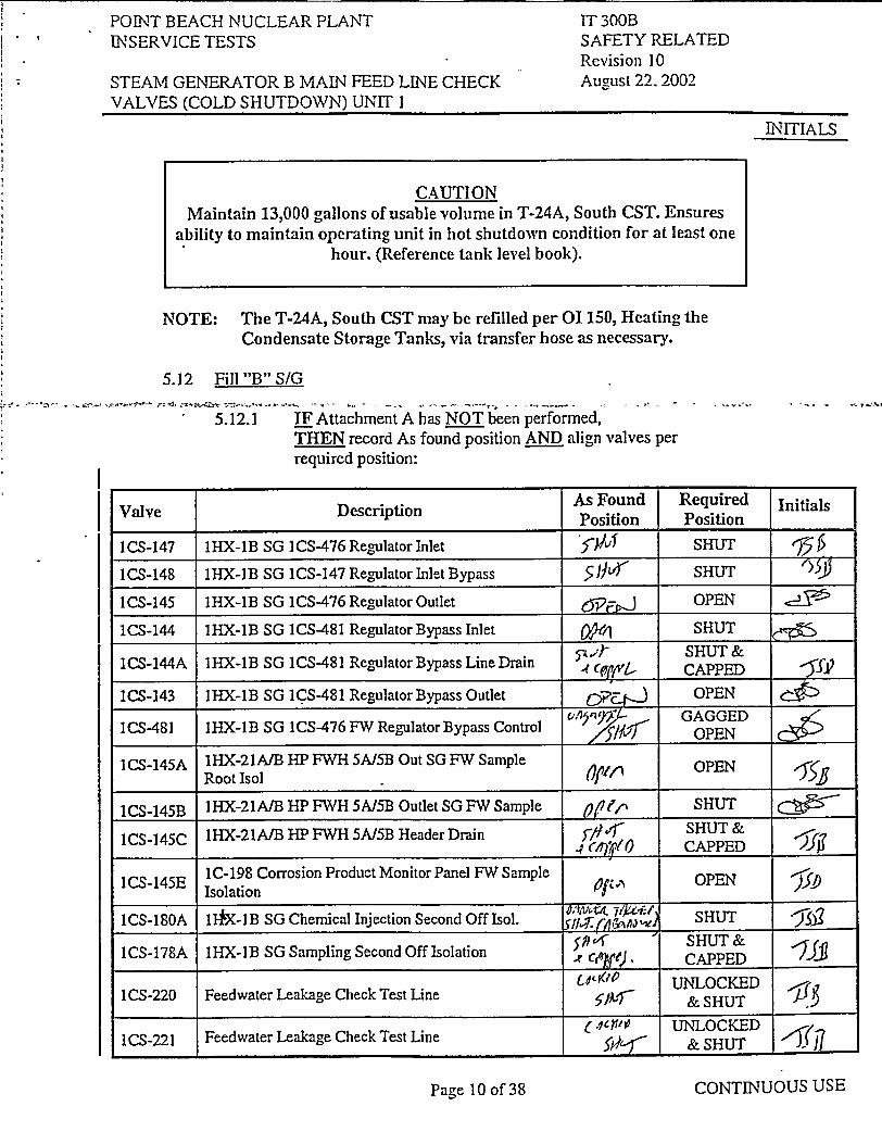
NOTE: The T-24A, South CST may be refilled per 01 150, Heating the Condensate Storage Tanks, via transfer hose as necessary.
5.12 Fill "B" S/G
5.12.1 IF Attachment A has NOT been performed, THEN record As found position AND align valves per required position:
CONTINUOUS USE
INITIALS
CAUTION Maintain 13,000 gallons of usable volume in T-24A, South CST. Ensures
ability to maintain operating unit in hot shutdown condition for at least one hour. (Reference tank level book).
Valve Description As Found Required Initials Valve__escription_ Position Position
ICS-147 1HX-IB SG ICS-476 Regulator Inlet SHUT
1CS-148 1HX-1B SG 1CS-147 Regulator Inlet Bypass ,153 SHUT
ICS-145 1HX-IB SG ICS-476 Regulator Outlet OPEN
ICS-144 IHX-1B SG ICS-481 Regulator Bypass Inlet well SHUT
ICS-144A 1HX-1B SG ICS-481 Regulator Bypass Line Drain SHUT & -? CAPPED 4fL
1CS-143 1HX-1B SG ICS-481 Regulator Bypass Outlet OPE ,1 OPEN o,'• j... GAGGED (
ICS-481 IHX-IB SG ICS-476 FW Regulator Bypass Control G GED _____ x7f•i- OPEN ___
I CS-145A IHX-21A/B HP FWH 5A/5B Out SG FW Sample Root Isol Of/, OPEN
1CS-145B IHX-21A/B HP FWH 5AI5B Outlet SG FW Sample ()e ,^ SHUT
1CS-145C IHX-21A/B HP FWH 5AI5B Header Drain 3-"14. SHUT & ________4 (4)VN CAPPED
1IC-198 Corrosion Product Monitor Panel FW Sample z A OPEN ICS-145E Isolation Of
ICS-180A l-fX-lB SG Chemical Injection Second Off Isol. fil,(, , SHUT
1CS-178A IHX-IB SG Sampling Second Off Isolation 59',, SHUT & ., UNfLO. CAPPED
1CS-220 Feedwater Leakage Check Test Line t1•IP UNLOCKED 1Ch v4& SHUT if
IS21 Feedwater Leakage Check Test Line 6 dw UNLOCKED I1ICS291- & SHUT iJ
INITIALS
Page 10 of 38
POINT BEACH NUCLEAR PLANT INSERVICE TESTS
STEAM GENERATOR B MAIN FEED LINE CHECK VALVES (COLD SHUTDOWN) UNIT 1
IT 300B SAFETY RELATED Revision 10 August 22, 2002
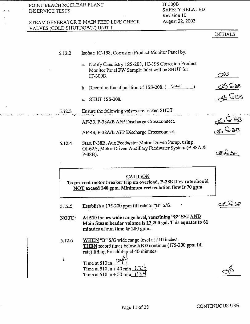
5.12.2 Isolate 1C-198, Corrosion Product Monitor Panel by:
a. Notify Chemistry ISS-208, IC-198 Corrosion Product Monitor Panel FW Sample Inlet will be SHUT for IT-300B.
b. Record as found position of 1SS-208. ( SI- )
c. SHUT 1SS-208.
5.12.3 Ensure the following valves are locked SHUT AF-30, P-38A/B AP Discharge Crossconnect.
AF-43, P-38A/B AFP Discharge Crossconnect.
5.12.4 Start P-38B, Aux Feedwater Motor-Driven Pump, using O1-62A, Motor-Driven Auxiliary Feedwater System (P-38A &
P-38B).
5.12.5 Establish a 175-200 gpm fill rate to "B" SIG.
NOTE: At 510 inches wide range level, remaining '"3" SIG AND Main Steam header volume is 12,200 gal. This equates to 61 minutes of run time @ 200 gpm.
5.12.6 WHEN "B" S/G wide range level at 510 inches, THEN record times below AND continue (175-200 gpm fill rate) filling for additional 40 minutes.
Time at 510 in to ý
Time at 510 in + 40 min (12 Time at 510 in +50 min jIL4
CONTINUOUS USE
INITIALS
CAUTION
To prevent motor breaker trip on overload, P-38B flow rate should NOT exceed 240 gpm. Minimum recirculation flow is 70 gpm
4
Page I11 of 38

POINT BEACH NUCLEAR PLANT LNSERVICE TESTS
STEAM GENERATOR B MAIN FEED LINE CHECK VALVES (COLD SHUTDOWN) UNIT I
IT 300B SAFETY RELATED Revision 10 August 22, 2002
5.12.7 WHEN at Time at 510 in + 40, THEN THROTTLE fill rate to approximately 100 gpm AND establish communication with operator at "B" S/G manual vent within Time at 510 in + 50 min
NOTE: The "B" SIG pressure on PPCS will show an increase when almost solid.
NOTE: Individual stationed at vent will have indication (change in sound) coming from vent just prior to "B" SIG going solid.
5.12.8 Continue filling "B" S/G AND steam line.
a. Just prior to going solid, minimize auxiliary feed flow.
b. WHEN water observed from vent, THEN STOP P-38B, Aux Feedwater Motor-Driven Pump.
5.12.9 SHUT IMS-248, 1HX-1B SG Vent.
5.13 Ensure "B" S/G Metal Temperature Greater Than OR Egual to 70'F.
5.13.1 Obtain hand held'pyrometer I adapter cable from C-59.
5.13.2 Perform either 5.13.3 OR 5.13.4. (Mark steps NOT used as N/A)
5.13.3 Plug in adapter cable at thermocouple junction box located on "B" S/G missile shield wall AND record readings:
a. TE-2022A, 1HX-IB SG Shell Temperature Thermocouple Above feedwater inlet 9i -F
CWý.' 5A
CONTINUOUS USE
INITIALS
CAUTION
Ensure AF-4014, P-38B AFP Mini Recirc Control, opens when feedflow to "B" SIG is less than OR equal to 75 gpm.
I
INITIAL
Pace 12 of 38
POINT BEACH NUCLEAR PLANT INSERVICE TESTS
STEAM GENERATOR B MAiN FEED LINE CHECK VALVES (COLD SHUTDOWN) UNIT I
IT 300B SAFETY RELATED Revision 10 August 22, 2002
IJNITIALS
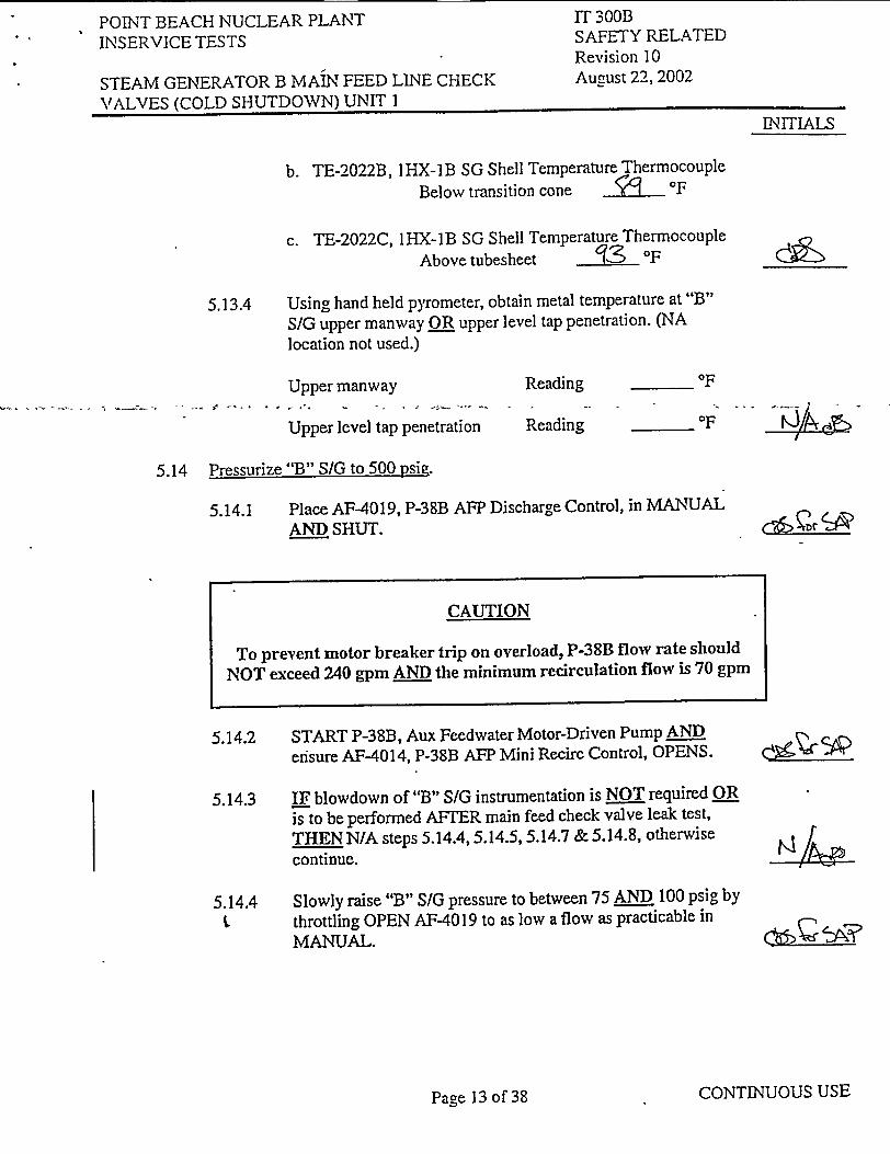
b. TE-2022B, IHX-1B SG Shell Temperature Thermocouple Below transition cone O 0F
c. TE-2022C, lHX-1B SG Shell Temperature Thermocouple Above tubesheet ,--3 OF
5.13.4 Using hand held pyrometer, obtain metal temperature at "B" S/G upper manway OR upper level tap penetration. (NA location not used.)
Upper manway
Upper level tap penetration
Reading
Reading
OF
_OF
5.14 Pressurize "B" S/G to 500 psig.
5.14.1 Place AF-4019, P-38B AFP Discharge Control, in MANUAL AND SHUT.
5.14.2 START P-38B, Aux Feedwater Motor-Driven Pump AND ensure AF-4014, P-38B AFP Mini Recirc Control, OPENS.
5.14.3 IF blowdown of"B" S/G instrumentation is NOT required OR is to be performed AFTER main feed check valve leak test,
THEN N/A steps 5.14.4, 5.14.5, 5.14.7 & 5.14.8, otherwise continue.
5.14.4 Slowly raise "B" S/G pressure to between 75 AN.D 100 psig by
throttling OPEN AF-4019 to as low a flow as practicable in MANUAL.
CONTINUOUS USE
CAUTION
To prevent motor breaker trip on overload, P-38B flow rate should
NOT exceed 240 gpm AND the minimum recirculation flow is 70 gpm
NIIAS-
1ý CýK Ir
-/n,
Pace 13 of 38

POINT BEACH NUCLEAR PLANT INSERVICE TESTS
STEAM GENERATOR B MAIN FEED LINE CHECK VALVES (COLD SHUTDOWN) UNIT I
IT 300B SAFETY RELATED Revision 10 August 22, 2002
5.14.5 Stabilize "B" S/G pressure between 75 AND 100 psig using AFW flow.
a. Throttle AFW flow as required, using AF-4019.
b. IF required to hold "B" S/G pressure, THEN establish "B" S/G blowdown flow as follows. (N/A steps not used).
1. OPEN IMS-5959, IHX-1B SG Blowdown Isolation.
.. . 2. OPEN 1MS-2040, ITo-26 SGBD Tank Outlet Control.
3. Throttle IMS-274, 1HX-IB SG Blowdown to 1T-26 SGBD Tank Throttle.
4. IF required, THEN start P-49 Blowdown Tank Pump.
5.14.6 IF blowdown flow is established to stabilize "B" S/G pressure, THEN record flow rate AND time on PBF-205 1.
5.14.7 Notify I&C to blowdown "B" S/G instrumentation.
5.14.8 Hold until notified by I&C of task completion above.
5.14.9 Slowly raise "B" S/G pressure between 500 AND 520 psig by throttling AF-4019 to as low a flow as practicable in MANUAL.
5.14.10 Stabilize "B" S/G pressure between 500 AND 520 psig using AFW flow
a. Throttle AFW flow as required, using AF-4019
b. IF required to hold "B" S/G pressure, THEN establish "B" S/G blowdown flow as follows. (N/A steps not used).
1. OPEN IMS-5959, 1HX-IB SG Blowdown Isolation
2. OPEN 1MS-2040, IT-26 SGBD Tank Outlet Control.
CONTINUOUS USE
INITIALS
t.
C&1ý5-
dý>
CQ5ýý ýy-ZR
Pace 14 of' 38

POINT BEACH NUCLEAR PLANT INSERVICE TESTS
STEAM GENERATOR B MAIN FEED LINE CHECK VALVES (COLD SHUTDOWN) UNIT I
IT 300B SAFETY RELATED Revision 10 August 22,2002
3. Throttle IMS-274, 1HX-1B SG Blowdown to IT-26 SGBD Tank Throttle.
4. IFrequired, THEN start P-49 Blowdown Tank Pump.
5.15 Check Flow Indicator Test Rig connected to ICS-145C, 1HX-21A/B HP FWH 5A/5B Header Drain,
5.15.1 IF NOT connected, THEN connect test rig per Attachment A, step 2.0.
5.16 Check effluent hose attached to 1CS-144A, IHX-1B SG.1CS-481 Regulator Bypass Line Drain.
5.16.1 IF NOT connected, THEN remove cap AND attach hose to 1CS-144A
a. Route hose to a local floor drain.
b. Secure to prevent end whip.
5.17 Seat Leakage Test of 1CS-476AA, IHX-1B SG Feedwater Check
5.17.1 Ensure OPEN I CS-221, Feedwater Leakage Check Test Line.
5.17.2 OPEN the following valves:
a. 1CS-145A, 1HX-21A/B HP FWH 5AI5B Outlet Sample.
b. 1CS-145C, IHX-21A/B HP FWH 5AI5B Header Drain.
c. Record test manifold pressure. .. '. psig.c!6ý
CONTINUOUS USE
INITIALS
CAUTION
System is pressurized to 500 psig. All drain hoses must be restrained to prevent end whip AND personnel injury.
Zý5
I
Pagye 15 of 38

POINT BEACH NUCLEAR PLANT INSERVICE TESTS
STEAM GENERATOR B MAIN FEED LINE CHECK VALVES (COLD SHUTDOWN) UNIT I
IT 300B SAFETY RELATED Revision 10 August 22, 2002
5.17.3 While observing test manifold pressure perform the following:
a. Throttle OPEN manifold outlet valve until pressure drops rapidly to less than 100 psig, indicating ICS-476AA seated.
b. SHUT OR Throttle manifold outlet valve as required to maintain 20 to 25 psig backpressure on manifold pressure gauge.
c. IF 1 CS-476AA backpressure is less than 20 psig OR pressure drops to less than 20 psig (as a result of trying to seat check valve) AND does NOT recover to 20 psig (due to check valve leakage), THEN momentarily Throttle OPEN I CS-220 to restore backpressure to 20-25 psig BEFORE recording data.
d. IF test manifold flow is less than 25 gpm, THEN continue with step 5.17.3.e while marking step 5.17.4 as N/A. (Otherwise mark Step 5.17.3.e as N/A)
e. WHEN a stable backpressure AND stable "B" S/G test pressure is achieved, THEN record on Attachment C:
S
0
0
Test rig pressure SG B Pressure Measured Leakage Calculated expected valve leakage.
5.17.4 With test manifold flow of approximately 25 gpm AND while observing test manifQld pressure perform the following:
a. Throttle OPEN 1CS-144A, 1HX-1B SG 1CS-481 Regulator Bypass Line Drain, UNTIL manifold pressure drops rapidly to less than 100 psig, indicating ICS-476AA, has seated.
b. SHUT 1CS-144A
c. IF full flow established through 1CS-144A AND manifold pressure remains greater than 100 psig, THEN Throttle OPEN manifold outlet valve until I CS-476AA seats.
CONTINUOUS USE
INITIALSINITIALS
(2ý'&aB
olb"o' I %,,,
Page 16 of 38
POINT BEACH NUCLEAR PLANT INSERVICE TESTS
STEAM GENERATOR B MAIN FEED LINE CHECK VALVES (COLD SHUTDOWN) UNIT I
IT 300B SAFETY RELATED Revision 10 August 22, 2002
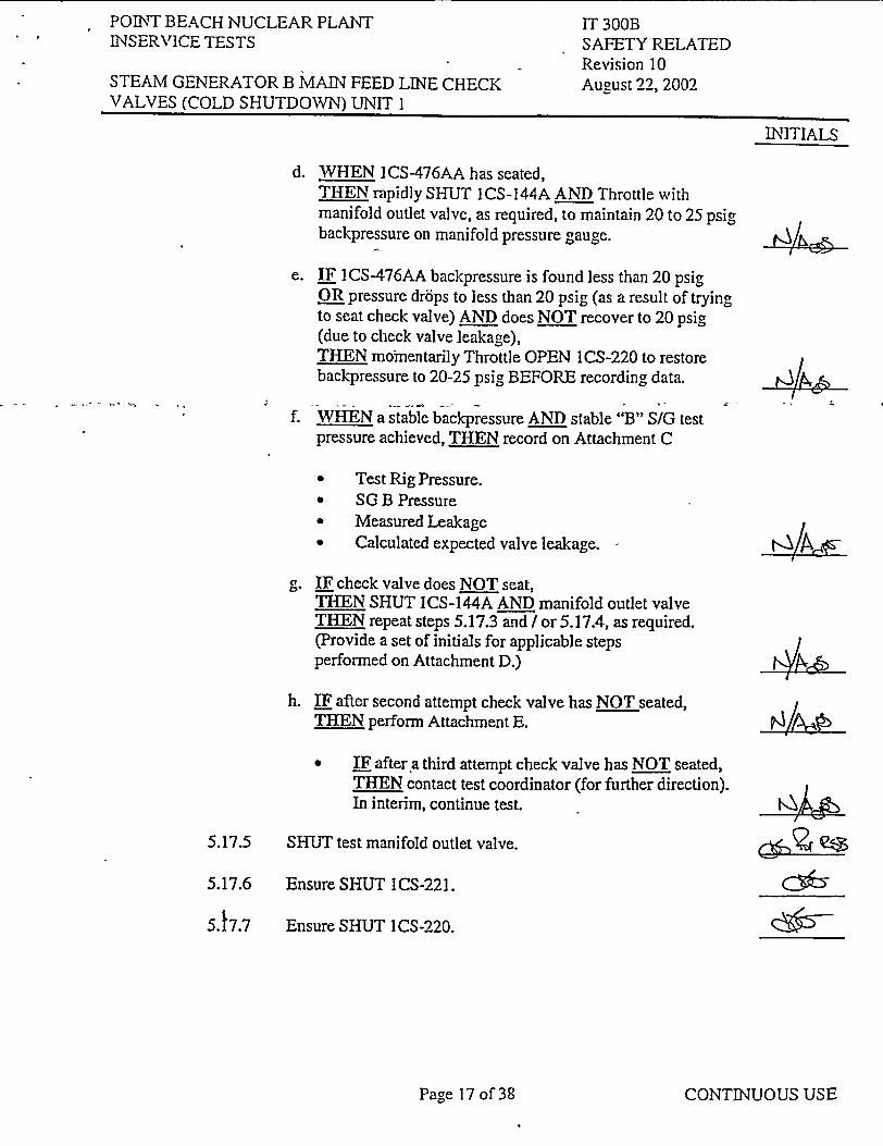
d. WHEN I CS-476AA has seated, THEN rapidly SHUT I CS-144A AND Throttle with manifold outlet valve, as required, to maintain 20 to 25 psig backpressure on manifold pressure gauge.
e. IF I CS-476AA backpressure is found less than 20 psig OR pressure dr6ps to less than 20 psig (as a result of trying to seat check valve) AND does NOT recover to 20 psiig (due to check valve leakage), THEN momientarily Throttle OPEN ICS-220 to restore backpressure to 20-25 psig BEFORE recording data.
f. WHEN a stable backpressure AND stable "B" S/G test pressure achieved, THEN record on Attachment C
S
S
S
S
Test Rig Pressure. SG B Pressure Measured Leakage Calculated expected valve leakage.
IF check valve does NOT seat, THEN SHUT ICS-144A AND manifold outlet valve THEN repeat steps 5.17.3 and I or 5.17.4, as required. (Provide a set of initials for applicable steps performed on Attachment D.)
h. IF after second attempt check valve has NOT seated, THEN perform Attachment E.
IF after a third attempt check valve has NOT seated, THEN contact test coordinator (for further direction). In interim, continue test.
5.17.5 SHUT test manifold outlet valve.
5.17.6 Ensure SHUT 1CS-221.
Ensure SHUT 1CS-220.
CONTINUOUS USE
INITIALS
5.17.7
INITIALS
Page 17 of 38
POINT BEACH NUCLEAR PLANT IN-SERVICE TESTS
STEAM GENERATOR B MAIN FEED LINE CHECK VALVES (COLD SHUTDOWN) UNIT I
IT 300B SAFETY RELATED Revision 10 August 22, 2002
5.17.8 IF seat leakage test of I CS-476BB, 1HX-1B SG Feedwater Check is NOT to be performed, THEN restore Feed Line Drain Valves as follows.
a. SHUT ICS-145C, 1HX-21A/B HP FWH 5A/5B Header Drain.
b. Disconnect test manifold at I CS-145C AND install cap.
c. Ensure SHUT ICS-144A remove hose AND install cap.
d. OPEN I CS-145R.
e. Ungag 1CS-481, 1HX-1B SG ICS-476FW Regulator Bypass Control as follows:
1. While depressing I CS-481 Bypass Reset, start ungagging 1CS-481.
2. Once started, release 1CS-481 reset switch AND fully ungag I CS-481.
3. Ensure I CS-481 is ungagged with a locked handwheel.
f. Restore IC-198, Corrosion Product Monitor Panel FW Sample, alignment as follows:
-44
I�I
1. Notify Chemistry 1SS-208, IC-198 Corrosion Product Monitor Panel FW Sample Inlet will be returned to "As found" position.
2. Restore lSS-208 to "As found" position recorded in step 5.12.2 OR Attachment A as applicable.
CONTINUOUS USE
INITIALS
Page 18 of 38

POINT BEACH NUCLEAR PLANT INSERVICE TESTS
STEAM GENERATOR B MAIN FEED LINE CHECK VALVES (COLD SHUTDOWN) UNIT I
IT 300B SAFETY RELATED Revision 10 August 22, 2002
5.18 Seat leakaae Test of ICS-476BB. 1-IHX-IB SG Feedwater Check
5.18.1 Ensure OPEN I CS-220, Feedwater Leakage Check Test Line.
5.18.9 S... OPEN the following v"aes:-....
a. 1CS-145A, IHX-21A/B HP FWH 5A/5B Outlet Sample.
b. ICS-145C, 1HX-21AIB HP FWH 5A/5B Header Drain.
c. Record test manifold pressure. 5-0 - psig.
5.18.3 While observing test manifold pressure perform the following:
a. Throttle OPEN manifold outlet valve until pressure drops rapidly to less than 100 psig, indicating 1CS-476BB, has seated.
b. SHUT OR Throttle manifold outlet valve as required to maintain 20 to 25 psig backpressure on manifold pressure gage.
CONTINUOUS USE
INITIALS
CAUTION
System is pressurized to 500 psig. All drain hoses must be restrained to prevent end whip AND personnel injury.
Cý5
Q Qjs
cg!ý)Qa az
Pace 19 of 38
POINT BEACH NUCLEAR PLANT INSERVICE TESTS
STEAM GENERATOR B MAIN FEED LINE CHECK VALVES (COLD SHUTDOWN) UNIT I
IT 300B SAFETY RELATED Revision 10 August 22, 2002
c. IF ICS-476BB backpressure is found to be less than 20 psig -OR pressure drops to less than 20 psig (as a result of trying to seat check valve) AND does NOT recover to 20 psig (due to check valve leakage), THEN momentarily Throttle OPEN I CS-221 to restore backpressure to 20-25 psig BEFORE recording data.
d. IF test manifold flow is less than 25 gpm THEN continue with step 5.18.3.e while marking step 5.18.4 as N/A. (Otherwise mark Step 5.18.3.e as N/A)
e. VWHEN a stable backpressvire AINI)_stable "1" SIG test pressure is achieved, THEN Lrecord on Attachment C:
S
S.
S
U
Test Rig Pressure, SG B Pressure Measured Leakage Calculated expected valve leakage.
5.18.4 With test manifold flow of approximately 25 gpm AND while observing test manifold pressure perform the following:
a. Throttle OPEN 1CS-144A, 1HX-1B SG ICS-481 Regulator Bypass Line Drain until manifold pressure drops rapidly to less than 100 psig, indicating ICS-476BB has seated,
b. SHUT ICS-144A.
c. IF full flow is established through ICS-144A AND manifold pressure remains greater than 100 psig, THEN Throttle OPEN manifold outlet valve until 1CS-476BB seats.
d. WHEN I CS-476BB has seated, THEN rapidly SHUT 1CS-144A AND Throttle with manifold outlet valve, as required, to maintain 20 to 25 psig backpressure on manifold pressure gauge.
4A�
CONTINUOUS USE
INITIALS
MNIic
INITIALS
drb Z. iýA3
Pagre 20 of 38
POINT BEACH NUCLEAR PLANT INSERVICE TESTS
STEAM GENERATOR B MAIN FEED LINE CHECK VALVES (COLD SHUTDOWN) UNIT I
IT 300B SAFETY RELATED Revision 10 August 22, 2002
e. IF ICS-476BB backpressure is found to be less than 20 psig OR pressure drops to less than 20 psig (as a result of trying to seat check valve) AND does NOT recover to 20 psig (due to check valve leakage), THEN momentarily Throttle OPEN 1CS-221 to restore backpressure to 20-25 psig BEFORE recording data.
f. WHEN a stable backpressure AND stable "B" S/G test pressure is achieved, THEN record on Attachment C :
0
S
S
0
Test Rig Pressure
Measured Leakage Calculated expected valve leakage.
g- IF check valve does NOT seat, THEN shut 1CS-144A AND manifold valve AND repeat steps 5.18.3 and/or 5.18.4, as required. (Provide a set of initials for applicable steps performed on Attachment D.)
h. IF after second attempt check valve has NOT seated THEN perform Attachment F.
IF after third attempt check valve has NOT seated, THEN contact test coordinator for further direction. (In interim, continue with test).
5.18.5 SHUT test manifold outlet valve.
5.18.6 Ensure SHUT I CS-220.
5.18.7 Ensure SHUT ICS-221.
CONTINUOUS USE
INITIALS
1 -9&
0'6
Page 21 of 38

POINT BEACH NUCLEAR PLANT 1NSERVICE TESTS
STEAM GENERATOR B MAIN FEED LINE CHECK VALVES (COLD SHUTDOWN) UNIT I
IT 300B SAFETY RELATED Revision 10 August 22, 2002
! I
CONTINUOUS USE
INITIALS
5.18.8 IF seat leakage test of I CS-476AA is NOT to be performed, THEN restore Feed Line Drain Valves.
a. Shut ICS-145C, IHX-21A/B HP FWH 5A/5B Header Drain.
b. Disconnect test manifold at ICS-145C AND install cap.
c. Ensure SHUT ICS-144A remove hose AND install cap.
d. OPEN ICS-145B, IHX-21AIB HP FWH 5AI5B Outlet Sample.
e. Ungag ICS-481, 1HX-IB SG 1CS-476 FW Regulator Bypass Control.
1. While depressing 1CS-481 reset, start ungagging ICS-481.
2. Once started, release 1CS-481 reset switch AND fully ungag 1 CS-481.
3. Ensure ICS-481 is ungagged with a locked handwheel.
f. Restore IC-198, Corrosion Product Monitor Panel FW Sample alignment as follows:
"* Notify Chemistry ISS-208, 1C-198 Corrosion Product Manual Panel FW Sample Inlet will be returned to the "As found" position.
"* Restore I SS-208, to "As found" position recorded in step 5.12.2 OR Attachment A as applicable.
5.19 When Testing is Complete t
5.19.1 IF "B" S/G instrumentation blowdown is NOT required OR previously performed, THEN NIA step 5.19.2
/5
IV
I
I
tvb
Page 22 of 38
POLNT BEACH NUCLEAR PLANT INSERVICE TESTS
STEAM GENERATOR B MAIN FEED LINE CHECK VALVES (COLD SHUTDOWN) UNIT 1
IT 300B SAFETY RELATED Revision 10 August 22, 2002
INITIALS
5.19.2 IF required for I&C "B" SIG instrumentation blowdown, THEN perform the following:
a. Slowly lower "B" S/G pressure to between 75 AND 100 psig by throttling AF-4019 in MANUAL.
b. Stabilize "B" SIG pressure between 75 AND 100 psig using AFW flow.
* Throttle AFW flow as required, using AF-4019.
* IF required to hold "B".S'!C pressaire., THEN establish "B" S/G blowdown flow as follows. .(N/A steps not used).
(a) OPEN 1MS-5959, 1HX-1B SG Blowdown Isolation.
(b) OPEN 1MS-2040, 1T-26 SGBD Tank Outlet Control.
(c) Throttle 1MS-274, IHX-lB SG Blowdown to IT-26 SGBD Tank Throttle.
(d) IF required, THEN start P-49 Blowdown Tank Pump.
c. Place 1MS-2015, 1HX-1B SG Hdr Atmospheric Steam Dump Control, to MANUAL.
d. Notify I&C to blowdown "B" S/G instrumentation.
e. Hold until notified by I&C of task completion.
f. Place 1MS-2015, 1HX-1B SG Hdr Atmospheric Steam Dump Control, to AUTO.
WHEN the test is complete, THEN reduce flow AND STOP P-38B, Aux Feedwater Motor-Driven Pump using 01 62A.
4/A
CONTINUOUS USE
5A9.3
INITIALS
Page 23 of 38
POINT BEACH NUCLEAR PLANT INSERVICE TESTS
STEAM GENERATOR B MAIN FEED LINE CHECK VALVES (COLD SHUTDOWN) UNIT I
IT 300B SAFETY RELATED Revision 10 August 22, 2002
INITIALS
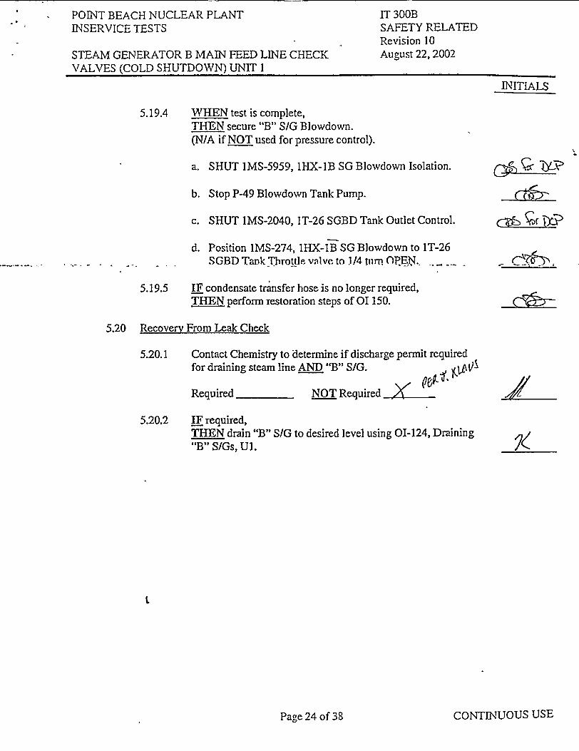
5.19.4 WHEN test is complete, THEN secure "B" S/G Blowdown. (NIA if NOT used for pressure control).
a. SHUT IMS-5959, 1HX-1B SG Blowdown Isolation.
b. Stop P-49 Blowdown Tank Pump.
c. SHUT 1MS-2040, IT-26 SGBD Tank Outlet Control.
d. Position 1MS-274, IHX-iB SG Blowdown to 1T-26 SGBD Tank Throttle valve to 1/4 turn OP .....
5.19.5 IF condensate transfer hose is no longer required, TH-EN perform restoration steps of 01150.
5.20 Recovery From Leak Check
c�SU•�'
5.20.1 Contact Chemistry to determine if discharge permit required for draining steam line AND "B" S/G. -,
Required NOT Required_
5.20.2 IF required, THEN drain "B" S/G to desired level using 01-124, Draining "B" S/Gs, Ul.
CONTINUOUS USEPage 24 of 38
POINT BEACH NUCLEAR PLANT INSERVICE TESTS
STEAM GENERATOR B MAIN FEED LINE CHECK VALVES (COLD SHUTDOWN) UNIT I
IT 300B SAFETY RELATED Revision 10 August 22, 2002
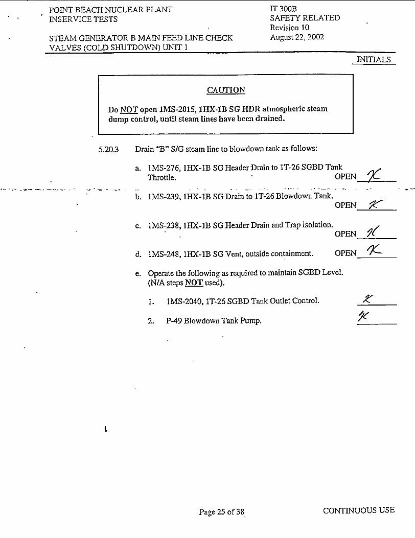
5.20.3 Drain "B" S/G steam line to blowdown tank as follows:
a. IMS-276, IHX-1B SG Header Drain to 1T-26 SGBD Tank Throttle. OPEN
b. IMS-239, lHX-IB SG Drain to IT-26 Blowdown Tank. OPEN
c. 1MS-238, lHX-1B SG Header Drain and Trap isolation. OPEN /
d. 1MS-248, 1HX-1B SG Vent, outside containment. OPEN_ __
e. Operate the following as required to maintain SGBD Level. (N/A steps NOT used).
1. 1MS-2040, 1T-26 SGBD Tank Outlet Control.
2. P-49 Blowdown Tank Pump.
CONTINUOUS USE
INITIALS
CAUTION
Do NOT open 1MS-2015, 1HX-1B SG HDR atmospheric steam dump control, until steam lines have been drained.
ýe
Page 25 of 38
POINT BEACH NUCLEAR PLANT INSERVICE TESTS
STEAM GENERATOR B MAIN FEED LINE CHECK VALVES (COLD SHUTDOWN) UNIT I
IT 300B SAFETY RELATED Revision 10 August 22, 2002
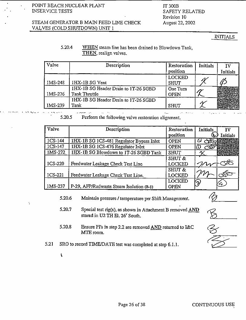
5.20.4 WHEN steam line has been drained to Blowdown Tank, THEN, realign valves.
5.20.5 Perform the following valve restoration alignment.
5.20.6 Maintain pressure I temperature per Shift Management.
5.20.7 Special test rig(s), as shown in Attachment B removed AND stored in U2 TH El. 26' South.
5.20.8 Ensure Pr's in step 2.2 are removed AND returned to I&C MTE room.
5.21 SRO to record TIME/DATE test was completed at step 6.1.1.
CONTINUOUS USE
INITIALS
Valve Description Restoration Initials IV position 1) Initials
1CS-144 IHX-1B SG 1CS-481 Regulator Bypass Inlet OPEN 50 !k 1CS-147 1HX-1B SG ICS-476 Regulator Inlet OPEN (D C-4 IMS-272 IHX-1B SG Blowdown to IT-26 SGBD Tank SHUT N
SHUT & 1 CS-220 Feedwater Leakage Check Test Line LOCKED " i,
SHUT & ICS-221 Feedwater Leakage Check Test Line. LOCKED
LOCKEDN IMS-237 P-29, AFPlRadwaste Steam Isolation (B-1) OPEN_________
(�5-
Page 26 of 38
POrINT BEACH NUCLEAR PLANT INSERVICE TESTS
STEAM GENERATOR B MAIN FEED LINE CHECK
VALVES (COLD SHUTDOWN) UNIT I
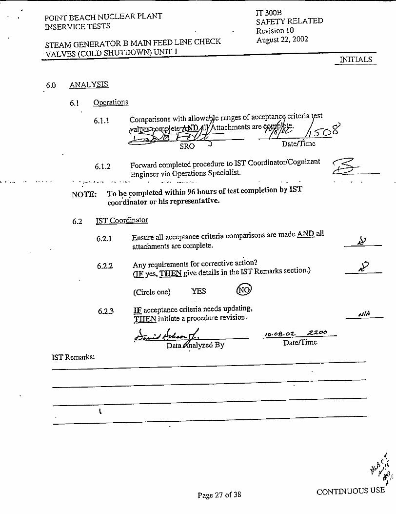
6.0 ANALYSIS
6.1 Operations
IT 300B SAFETY RELATED Revision 10 August 22, 2002
INITIALS
IST Remarks:
Page 27 of 38CONTINUOUS USE
6.1.1 Comparison h allowae ranges of acceptanc criteria est
= W e• _ttachments are eC i• j"--08
SRO Date ime
6.1.2 Forward completed procedure to IST Coordinator/Cognizant Engineer via Operations Specialist.
NOTE: To be completed within 96 hours of test completion by IST
coordinator or his representative.
6.2 IST Coordinator
6.2.1 Ensure all acceptance criteria comparisons are made AND all
attachments are complete.
6.2.2 Any requirements for corrective action? QE1 yes, THEN give details in the IST Remarks section.)
(Circle one) YES
6.2.3 IF acceptance criteria needs updating,
THE N initiate a procedure revision.
A.r/,. m"0,.o13-.07 2=00
Data Analyzed By DatefTime
AV9
POf'T bEACH NUCLEAR PLANT INSERVICE TESTS
STEAM GENERATOR B MAIN FEED LINE CHECK VALVES (COLD SHUTDOWN) UNIT I
IT 300B SAFETY RELATED Revision 10 August 22, 2002
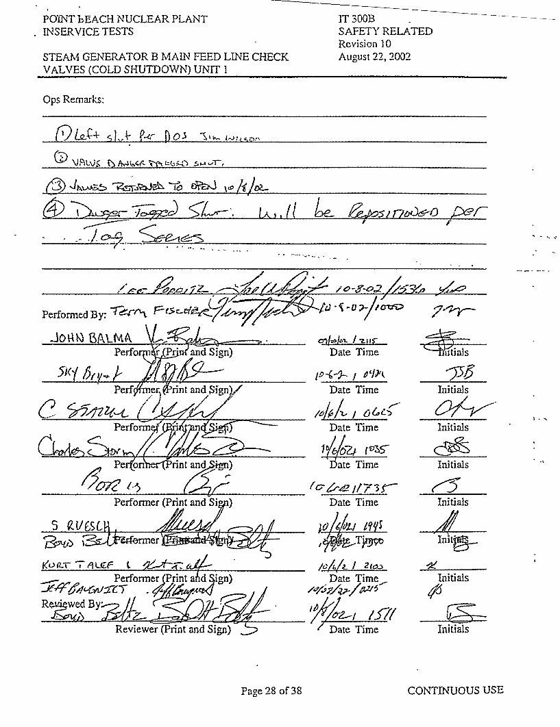
Ops Remarks:
QLJ~4- DL o -os
(3)~~~~ &3 \~$ ~ i~~OA
~ •~&~*. Uk'Del-
1Ž1m F- - �0���7/ 1�v
Pe<ýrfol z and
Perf er, rint and Sign)/
(e o rint and7in)
Performer (Print and Sig )
•, A
Performer (Print ahd ign)
RR e ted Byri Sn
Reviewer (P-rint and Sig.-n) 22ý;
al 016,/o,-. I ris
Date Time
1-" -- -I / ,, Date Time
4OZ4- / 6 Date Time
l/4672ý ( V
bate Time
Date Time
Date Time
Date Time
Initials
Initials
Initials
Initials
Initia_
Initials
Initials
CONTINUOUS USE
Performed By:
Page 28 of 38

POINT BEACH NUCLEAR PLANT INSERVICE TESTS
STEAM GENERATOR B MAIN FEED LINE CHECK VALVES (COLD SHUTDOWN) UNIT I
IT 300B SAFETY RELATED Revision 10 August 22, 2002
7.0 REFERENCES
7.1 WEP-91-102, Attachment, "Point Beach Units I & 2 Safety Evaluation and Report
Consolidation" Minimum Temperature for Pressurization.
7.2 Technical Specifications and FSAR figures.
7.2.1 TRM 3.7.3. Steam Generator Pressure and Temperature (P/T) Limits
7.2.2 TS 3.6.3, Containment Isolation Valves
7.2.3 TS 3.7.6, Condensate Storage Tank
7.2.4 TS 5.5.7, Inservice Testing Program.
7.2.5 FSAR Figures 5.2-3 and 5.2-4
7.3 ASME OM Code 95Ed. /96A, Code for Operation and Maintenance of Nuclear Power Plants.
7A Procedures.
7.4.1 OI-62A, Motor-Driven Auxiliary Feedwater System (P-38A & P-38B).
7.4.2 01-150, Heating the Condensate Storage Tanks.
7.4.3 01-124, Draining Steam Generators, Unit 1.
7.5 Drawings
7.5.1 M-201 Sheet 1, Main and Reheat System.
7.5.2 M-201 Sheet 3, S.G. Blowdown System.
7.5.3 M-202 Sheet 2, Feedwater System.
7.5.4 M-217, Sheet 1, Auxiliary Feedwater System, Unit 1.
7.5.5 M-222, Sheet 1, Secondary sample system
7.6 Miscellaneous procedures and forms
7.6.1 CL- 3A, Main Steam Valve Lineup Unit 1
CONTINUOUS USE
I
I
Page 29 of 38

POINrI-BEACH NUCLEAR PLANT INSERVICE TESTS
STEAM GENERATOR B MAIN FEED LINE CHECK VALVES (COLD SHUTDOWN) UNIT 1
IT 300B SAFETY RELATED Revision 10 August 22, 2002
7.6.2
7.6.3
PBF-2051, Steam Generator Blowdown Flow Rate Log Sheet.
TLB-34, T-24A/T-24B Condensate Storage Tanks
8.0 BASES
B-I, SCR 99-1106, Administrative Red Locks of closed system boundary valves.
CONTINUOUS USEPage 30 of 38
1

POiN\T, BEACH NUCLEAR PLANT INSERVICE TESTS
STEAM GENERATOR B MAIN FEED LINE CHECK VALVES (COLD SHUTDOWN) UNIT I
IT 300B SAFETY RELATED Revision 10 August 22, 2002
A7ITACHMENT A
I
CONTINUOUS USE
I
ATTACHMENT A Main Feed Line Fill And Flow Indicator Installation
1.0 Fill of Main Feed Line B:
1.1 Record As Found Position AND align the following valves:
Valve Component Description As Found Required INITIALS
Position Position
ICS-147 IHX-1B SG I CS-476 Regulator Inlet SHUT jj7A ,
I CS-148 1HX-1B SG 1CS-147 Regulator Inlet Bypass SHUT .
ICS-145 I-X-1B SG 1CS-476 Regulator Outlet OPEN .k
1CS-144 1HX-IB SG ICS-481 Regulator Bypass Inlet SHUT NIA /'
ICS-144A 1HX-IB SG 1CS-481 Regulator Bypass Line SHUT & Drain CAPPED N
]CS-143 1HX-1B SG ICS-481 Regulator Bypass Outlet OPEN Wk
1CS-481 1HX-1B SG 1CS-476 FW Regulator Bypass GAGGED RMi• Control OPEN 1Y
1CS-145A IHX-21A/B HP FWH 5A/5B Out SG FW OPEN Sample Root Isol
1CS-145B 1HX-21A/B HP FWH 5A/5B Outlet SG FW SHUT SampleSHT •/
1CS-145C IHX-21AIB HP FWH 5A/5B Header Drain SHUT & CAPPED L V, //'
lCS-145E IC-198 Corrosion Product Monitor Panel FW OPEN Sample Isolation _ _ _
ICS-180A 1HX-1B SG Chemical Injection Second Off SHUT Isolation •!.
ICS-178A IHX-IB SG Sampling Second Off Isolation SHUT & CAPPED pLhl UNLOCK
I CS-220 Feedwater Leakage Check Test Line ED & OPEN /,7
UNLOCK 1 CS-221 Feedwater Leakage Check Test Line ED &
OPEN ,
Page 31 of 38
POINT BEACH NUCLEAR PLANT INSERVICE TESTS
STEAM GENERATOR B MAIN FEED LINE CHECK VALVES (COLD SHUTDOWN) UNIT I
IT 300B SAFETY RELATED Revision 10 August 22, 2002
ATTACHMENT A MAIN FEED LINE FILL AND FLOW INDICATOR INSTALLATION (Cont.)
INITIALS
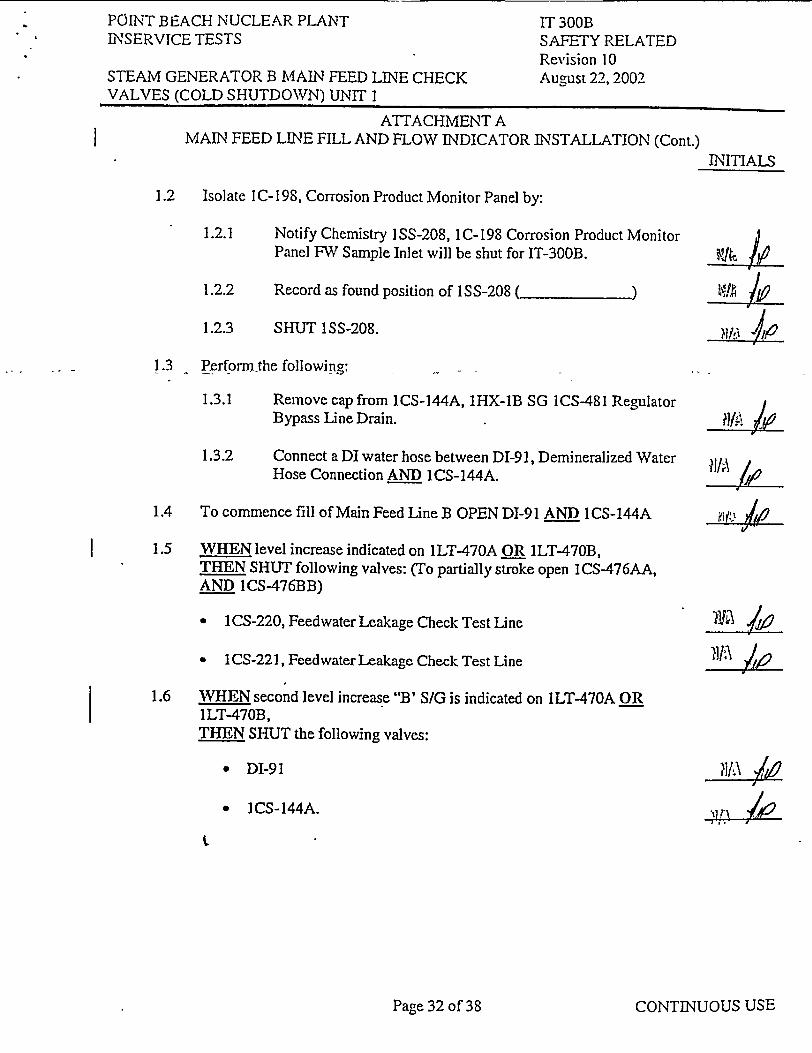
1.2 Isolate IC-198, Corrosion Product Monitor Panel by:
1.2.1
1.2.2
1.2.3
Notify Chemistry ISS-208, 1C-198 Corrosion Product Monitor Panel FW Sample Inlet will be shut for IT-300B.
Record as found position of 1SS-208 ( )
SHUT 1SS-208.
I liL
1.3 Perform-the following:
1.3.1 Remove cap from 1CS-144A, 1HX-IB SG 1CS-481 Regulator Bypass Line Drain.
1.3.2 Connect a DI water hose between DI-91, Demineralized Water Hose Connection AND ICS-144A.
1.4 To commence fill of Main Feed Line B OPEN DI-91 AND 1CS-144A
1.5 WHEN level increase indicated on 1LT-470A OR ILT-470B, THEN SHUT following valves: (To partially stroke open 1CS-476AA, AND 1CS-476BB)
01 CS-220, Feedwater Leakage Check Test Line
1CS-221, Feedwater Leakage Check Test Line
1.6 WHEN second level increase "B' S/G is indicated on ILT-470A OR ILT-470B, THEN SHUT the following valves:
?A\"* DI-91
"* ICS-144A.
CONTINUOUS USE
I
?)#,\ k1
I
Pag.e 32 of 38
POLNT BEACH NUCLEAR PLANT INSERVICE TESTS
STEAM GENERATOR B MAIN FEED LINE CHECK VALVES (COLD SHUTDOWN) UNIT I
IT300B SAFETY RELATED Revision 10 August 22, 2002
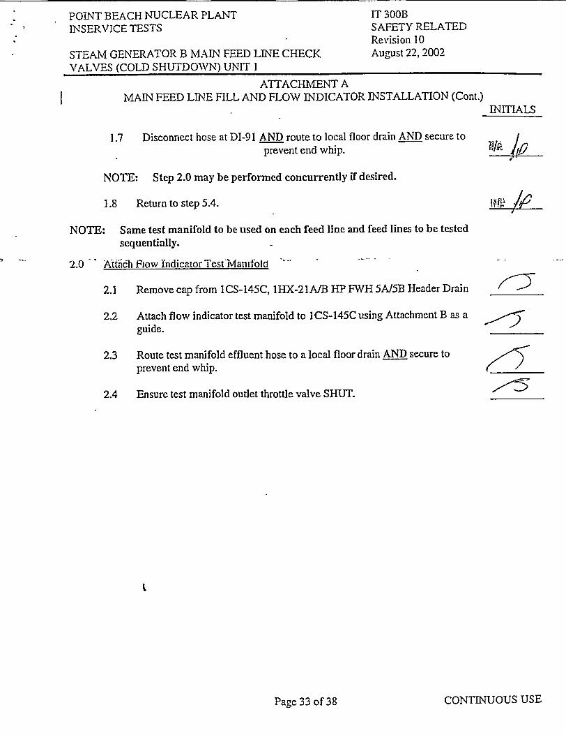
ATTACHMENT A MAIN FEED LINE FILL AND FLOW INDICATOR INSTALLATION (Cont.)
INITIALS
1.7 Disconnect hose at DI-91 AND route to local floor drain AND secure to prevent end whip. 14I• !,
NOTE: Step 2.0 may be performed concurrently if desired.
1.8 Return to step 5.4.
NOTE: Same test manifold to be used on each feed line and feed lines to be tested sequentially.
2.0 A•tfiidh Flow Indicator TestManifold
2.1 Remove cap from 1CS-145C, 1HX-21A/B HP FWH 5A15B Header Drain
2.2 Attach flow indicator test manifold to I CS-145C using Attachment B as a guide.
2.3 Route test manifold effluent hose to a local floor drain AND secure to prevent end whip.
2.4 Ensure test manifold outlet throttle valve SHUT.
j5�
2
:5
CONTINUOUS USE
I
Page 33 of 38

PO'ENT BEACH NUCLEAR PLANT INSERVICE TESTS
STEAM GENERATOR B MAIN FEED LINE CHECK VALVES (COLD SHUTDOWN) UNIT I
IT 300B SAFETY RELATED Revision 10 August 22, 2002
I
ICS-145C
CONTINUOUS USE
FD
Page 34 of 38
ATTACHMENT B FLOW INDICATOR TEST RIG
1.0 3/4 inch ICS Union
2.0 Oriega flow meter, Model No. FL-7325; Max pressure: 3000 psig;
Max temperature: 240'F; Flow range: 2.0-25 gpm (water)
3.0 Pressure gauge, 0-600 psig
4.0 3/4 inch Throttle valve
•5.0 _ Drain hose rated for greater than OR equal to 500 psig at 250 'F.

POiNT BEACH NUCLEAR PLANT INSERVICE TESTS
STEAM GENERATOR B MAIN FEED LINE CHECK VALVES (COLD SHUTDOWN) UNIT I
IT 300B SAFETY RELATED Revision 10 August 22, 2002
ATTACHMENT C TEST DATA SHEET
1.0 Record measured valve leakage at test AP from sections 5.17 & 5.18.
2.0 Calculate valve leakage expected at 1000 psid by dividing normal operating pressure by test pressure differential pressure (AP) and multiplying square root of value times measured leakage value at test AP.
2.1 Record test data AND calculations results in table below:
NOTE:. DP="B" S/G pressure minus Test Rig Pressure.
100sig x Measured leakage value = Leakage at 1000 psid
DP
NOTE: A leak rate of about 3.5 gpm at 500 psid will calculate out to about 5 gpm at 1000 psid
3.0 IF calculated leakage rate of any check valve at 1000 psid exceeds administrative limit of 5 gpm, THEN declare applicable valve inoperable AND notify engineering.
CONTINUOUS USE
INITIALS
5.17/5.18
5.1715.18
5.17V5.1 8
5. 15.8
INITIALS
Page 35 of 38

POiNT BEACH NUCLEAR PLANT INSERVICE TESTS
STEAM GENERATOR B MAIN FEED LINE CHECK VALVES (COLD SHUTDOWN) UNIT I
IT 300B SAFETY RELATED Revision 10 August 22, 2002
ATTACHMENT D MULTIPLE STEP PERFORMANCE
1.0 This attachment shall be completed to document multiple step performance. A separate copy of
this attachment shall be prepared for each step series requiring multiple performance. All copies
of'this attachment shall be attached to this procedure when the procedure is complete.
2.0 Refer to procedure steps when performing this attachment.
3.0 List procedure steps by number, including adequate spaces to record initials, as appropriate. For
components requiring independent verification or concurrent checks, provide for such checks on
the attachment.
4.0 -Complete the attachment by performing th-erbcedure-steps dirid recording the fe-luired data.:"
"Valve Number/Step sequence: Date:
Step Initials Initials Initials Initials Initials Initials Initials
CONTINUOUS USEPage 36 of 38
POINT BEACH NUCLEAR PLANT INSERVICE TESTS
STEAM GENERATOR B MAIN FEED LINE CHECK VALVES (COLD SHUTDOWN) UNIT I
IT 300B SAFETY RELATED Revision 10 August 22, 2002
RINITIALS
ATTACHMENT E I CS-476AA D/P Reestablishment
1.0 SHUT 1CS-143, 1HX-1B SG 1CS-481 Regulator Bypass Outlet.
2.0 OPEN ICS-144A, IHX-1B SG 1CS-481 Regulator Bypass Line Drain, to drain line between ICS-143 AND ICS-144, 1HX-1B SG 1CS-481 Regulator Bypass Inlet.
3.0 SHUT I CS-144A.
- 4.0 - .Rapidly OPEN ICS-143 to seat check valve.
5.0 Repeat steps 5.17.3 and / or 5.17.4, as required. (Provide a set of initials for applicable steps performed on Attachment D.)
CONTINUOUS USE
I
Page 37 of 38

POINT BEACH NUCLEAR PLANT LNSERVICE TESTS
STEAM GENERATOR B MAIN FEED LINE CHECK VALVES (COLD SHUTDOWN) UNIT I
IT'300B SAFETY RELATED Revision 10 August 22, 2002
INITIALS
ATTACHMENT F I CS-476BB D/P Reestablishment
1.0 SHUT 1CS-143, 1HX-1B SG I CS-481 Regulator Bypass Outlet.
2.0 OPEN 1CS-144A, IHX-1B SG ICS-481 Regulator Bypass Line Drain, to drain line between ICS-143 AND ICS-144, 1HX-1B SG ICS-481 Regulator Bypass Inlet.
3.0 SHUT I CS-144A.
4.0 Rapidly OPEN ICS-143 to seat check valve.
5.0 Repeat steps 5.18.3 and / or 5.18.4, as required. .(Provide a set of initials for applicable steps performed on Attachment D.)
Page 38 of 38 CONTINUOUS USE

DIR DATE C 10/8/2002V C 10/8/2002."
LOWER VALUE DB
10/8/2002
VALVEID I CS-00476AA I CS-00476BB
TESTCv-C Cv-C
UPPER5.00 5.00
LAST
Wisconsin Electric Company Point Beach Unit 1
Speed Load Report For IT-300 21:52:16
1.430 1.430
•SSN/A N/A
Yes Yes
% PJ
6" .., 1.0. of. to :L -7 1 C-5,
1
UPPER P