pof specs 2009-m
TRANSCRIPT
7/25/2019 POF Specs 2009-M
http://slidepdf.com/reader/full/pof-specs-2009-m 1/38
Specifications and requirements for intelligent pig inspection of pipelines, Version 2009 - M
Specifications and requirements forintelligent pig inspection of pipelines
Version 2009 – modifications underlined
Major modifications with regard to the previous version (V 3.2, February 2005) are
underlined in this copy. If differences between this copy and the version without the
changes indicated might occur, the version without the changes indicated must be used.

7/25/2019 POF Specs 2009-M
http://slidepdf.com/reader/full/pof-specs-2009-m 2/38
Specifications and requirements for intelligent pig inspection of pipelines, Version 2009- M
Contents Page
1.
Introduction 4
2. Standardisation 4
2.1 Definitions 4
2.2 Abbreviations 7
2.3 Geometrical parameters and interaction of anomalies 8
2.4
Nomenclature of features 8
2.5 Metal loss anomaly classification 9
2.6 Estimated repair factor 10
2.7 Resolution of measurement parameters 10
3. Health and safety 11
3.1
ATEX 11
3.2 NEC 505 12
4. Tool specifications 12
4.1 General tool specifications 12
4.2 MFL tool specifications 13
4.3 UT tool specifications – metal loss
detection 14
4.4 UT tool specifications – crack detection 14
4.5 Geometry tool specifications 15
4.6 Mapping tool specifications 16
5. Personnel qualification 16
6. Reporting requirements 16
6.1 Field report 17
6.2 Tool operational data 17
6.3 Tool calibration 18
6.4 Pipe tally 18

7/25/2019 POF Specs 2009-M
http://slidepdf.com/reader/full/pof-specs-2009-m 3/38
Specifications and requirements for intelligent pig inspection of pipelines, Version 2009- M
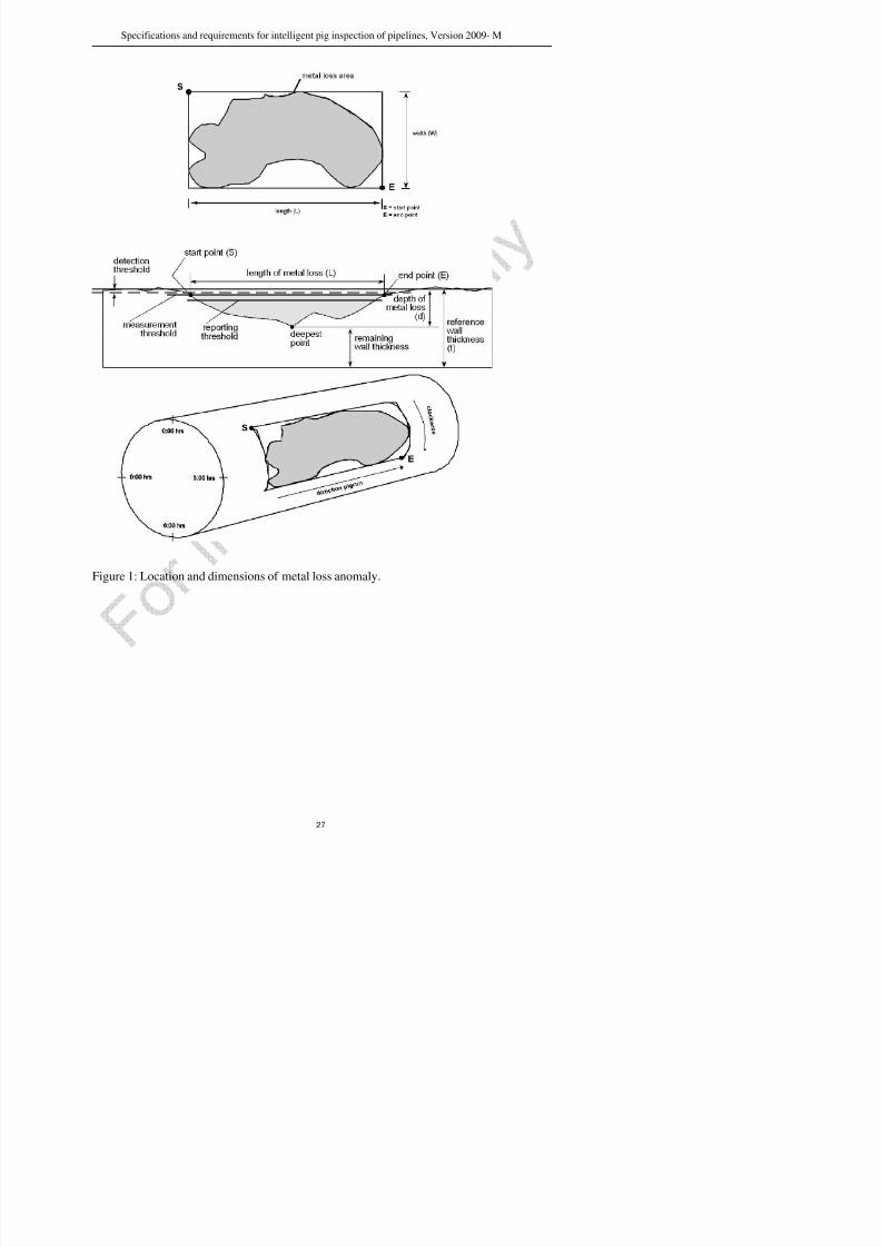
Figure 1: Location and dimensions of metal loss anomaly. 27
Figure 2: Graphical presentation of metal loss anomalies per dimension class. 28
Appendix 1: Operator’s guideline for defining specific details of the POF specifications 29
Appendix 2: ILI companies approached for comments to the draft version of these
specifications 32
Appendix 3a: Report structure, terminology and abbreviations 33
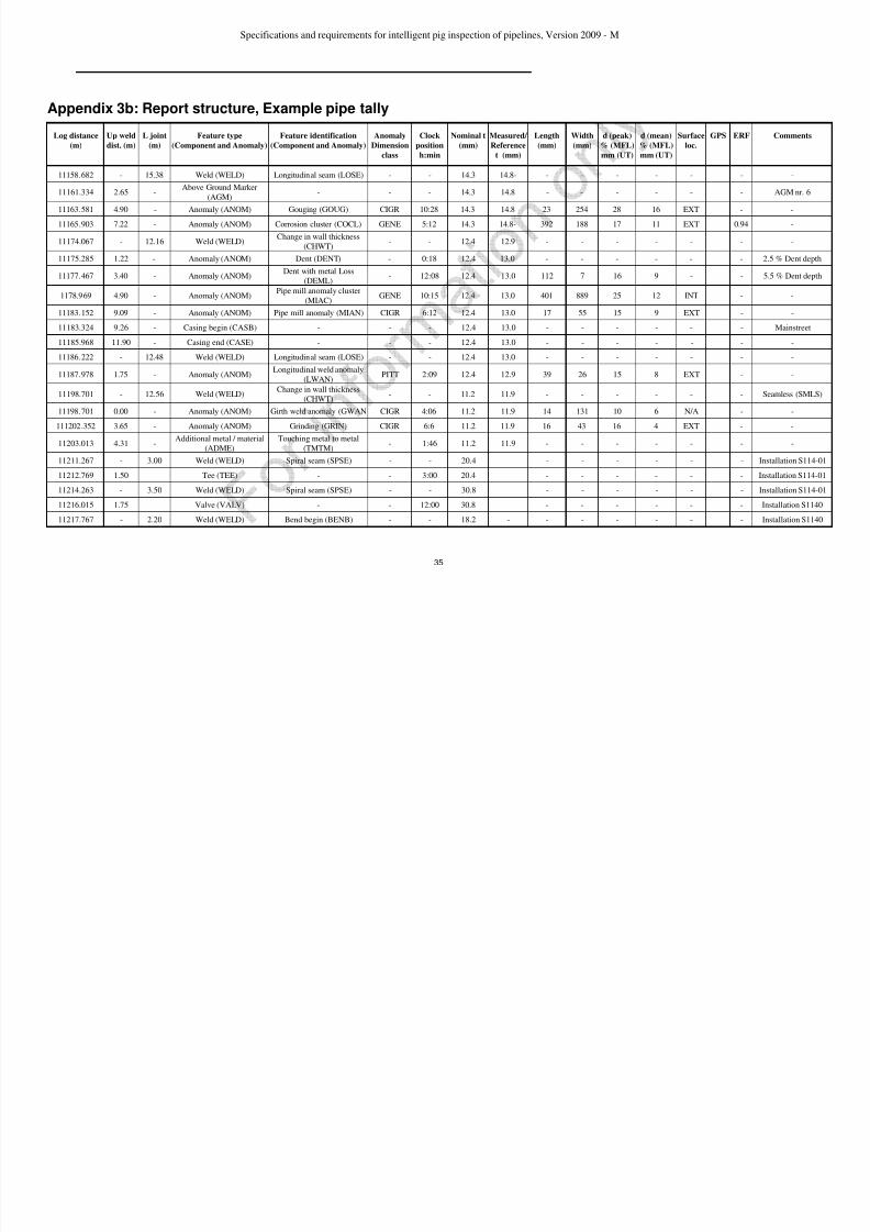
Appendix 3b: Report structure, Example pipe tally 35
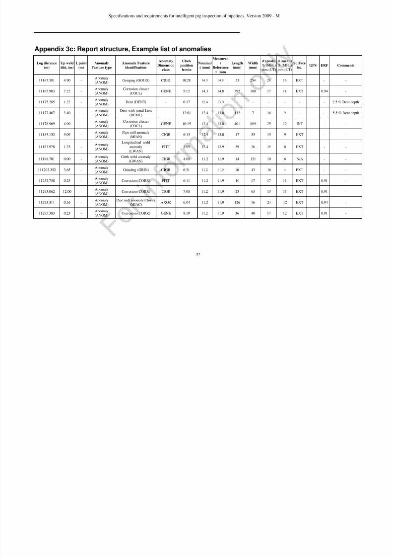
Appendix 3c: Report structure, Example list of anomalies 37
Appendix 3d: Report structure, example list of clusters 38

7/25/2019 POF Specs 2009-M
http://slidepdf.com/reader/full/pof-specs-2009-m 4/38
Specifications and requirements for intelligent pig inspection of pipelines, Version 2009- M
1. Introduction
This document specifies the advised operational and reporting requirements for tools to be
used for geometric measurement, pipeline mapping, metal loss, crack or other anomaly
detection during their passage through steel pipelines. The tools may pass through the
pipeline driven by the flow of a medium or may be towed by a vehicle or cable. The tools
may be automatic and self-contained or may be operated from outside the pipeline via
a data and power link.
This document has been reviewed and approved by the Pipeline Operator Forum (POF).It is stated however, that neither the members of the POF nor the Companies they represent
can be hold responsible for the fitness for purpose, completeness, accuracy and/or
application of this document.
A draft version of this document has been sent for comments to Intelligent Pigging
Contractors as listed in Appendix 2. The POF like to thank the Contractors for their
constructive feedback.
During the update of this specification, the API 1163 “In-Line Inspection Systems
Qualification Standard” have been reviewed and some terminology has been brought in-
line (e.g. confidence changed into certainty).
This document is intended to serve as a generic in-line-inspection specification and thereby
cannot cover all pipeline or pipeline operator specific issues. POF members and other users
of this specification are therefore free to add or change requirements based on their specific
pipeline situation. To support the pipeline operator in specifying/detailing some optional
items in this document, a guideline with a short description of these items is given in
Appendix 1.
2. Standardisation
2.1 Definitions
Above Ground Marker: A device near the outside of a pipeline that detects and
records the passage of an ILI tool or transmits a signal that is
detected and recorded by the tool. Reference magnets can be
applied to serve identical purposes.

7/25/2019 POF Specs 2009-M
http://slidepdf.com/reader/full/pof-specs-2009-m 5/38
Specifications and requirements for intelligent pig inspection of pipelines, Version 2009- M
Certainty: For the purpose of this specification, the probability that the
characteristics of a reported anomaly are within the stated
tolerances.Cluster: Two or more adjacent metal loss anomalies in the wall of a
pipe or in a weld that may interact to weaken the pipeline
more than either would individually.
Confidence level A statistical expression used to describe the mathematical
certainty with which a statement is made.
Corrosion: An electrochemical reaction of the pipe wall with its
environment causing a loss of metal.
Crack: A planar, two-dimensional feature with possible
displacement of the fracture surfaces.
Debris: Extraneous material in a pipeline which may interfere with
the ILI tool.
Dent: Distortion of the pipe wall resulting in a change of the
internal diameter but not necessarily resulting in localisedreduction of wall thickness.
Detection threshold: Minimum detectable feature dimension.
Feature: Indication, detected by non-destructive examination, of a
pipeline.
Geometry tool: Configuration pig designed to record conditions, such as
dents, wrinkles, ovalities, bend radius and angle, and
occasionally indications of significant internal corrosion, by sensing the shape of the internal surface of the pipe.
Grinding: Reduction in wall thickness by removal of material by hand
filing or power disk grinding.
Gouge: Mechanically induced metal-loss, which causes localised
elongated grooves or cavities.
Heat affected zone: The area around a weld where the metallurgy of the metal isaltered by the rise in temperature caused by the welding
process, but this is distinct from the weld itself. The width of
the heat-affected zone is typically limited to a few mm only,
depending on the welding process and parameters. For the
purpose of this specification it is considered to be within 2A
7/25/2019 POF Specs 2009-M
http://slidepdf.com/reader/full/pof-specs-2009-m 6/38
Specifications and requirements for intelligent pig inspection of pipelines, Version 2009- M
Lamination: Imperfection or discontinuity with a layered separation, that
may extend parallel or angular to the pipe wall surface.
Metal loss anomaly/feature: An area of pipe wall with a measurable reduction inthickness.
Mid wall feature: Any feature which does not run out to either the internal or
external surface.
Measured wall thickness: Measured wall thickness that is representative for a whole
pipe joint/component. For ultrasonic tools the value shall be
based on direct wall thickness measurements, for magnetic
tools on the inferred magnetic flux signals.
Measurement threshold: The minimum dimension(s) of a feature to make sizing
possible.
Nominal wall thickness: The wall thickness required by the specification for the
manufacture of the pipe.
Pig: Device that is driven through a pipeline for performing
various internal activities (depending on the pig type) such asseparating fluids, cleaning or inspecting the pipeline.
Pigging: Running of a pig or ILI tool in a pipeline.
Pig trap: An ancillary item of pipeline equipment, with associated
pipework and valves, for introducing a pig into a pipeline or
removing a pig from a pipeline.
Pipeline: A system of pipes and other components used for the
transportation of products between (but excluding) plants. Apipeline extends from pig trap to pig trap (including the pig
traps), or, if no pig trap is fitted, to the first isolation valve
within the plant boundaries or a more inward valve if so
nominated.
Pipe mill anomaly: An anomaly that arises during manufacture of the pipe, as for
instance a lap, sliver, lamination, non-metallic inclusion, roll
mark and seam weld anomaly.
Pipeline component: A feature such as a valve, tee, bend, weld, casing, marker, off
take, wall thickness change, etc. that is a fitted part of a
pipeline
Probability of Detection: The probability of a feature being detected by the intelligent

7/25/2019 POF Specs 2009-M
http://slidepdf.com/reader/full/pof-specs-2009-m 7/38
Specifications and requirements for intelligent pig inspection of pipelines, Version 2009- M
Sizing accuracy: Sizing accuracy is given by the interval with which a fixed
percentage of features will be sized. This fixed percentage is
stated as the certainty level.Spalling: Abrasion of the pipe surface resulting in shallow surface laps
and possibly hardening of the material below.
Weld: The area where joining has been done by welding and where
the material has undergone a melting and solidification
process. This area is distinct from the heat-affected zone, but
surrounded by it.
Weld anomaly: Anomaly in the weld or the heat affected zone.
Weld affected area: Area on both sides of a weld where ILI measurements are
effected by the geometry of the weld (e.g. due to sensor
dynamics).
2.2 Abbreviations
A Geometric parameter related to the wall thicknessAGM Above Ground Marker
D Metal loss anomaly depth
EC Eddy Current
EMAT Electro Magnetic Acoustic Transducer
ERF Estimated repair factor
GPS Global Positioning System
HFEC High Frequency Eddy Current
ILI In Line Inspection
L Anomaly/feature dimension (Length) in the axial direction and length of
crack in any direction
MAOP Maximum Allowable Operating Pressure
MOP Maximum Operating Pressure
MFL Magnetic Flux Leakage
NDE/NDT Non-Destructive Examination, Non-Destructive Testing
POD Probability Of Detection
POI P b bili Of Id ifi i
7/25/2019 POF Specs 2009-M
http://slidepdf.com/reader/full/pof-specs-2009-m 8/38
Specifications and requirements for intelligent pig inspection of pipelines, Version 2009- M
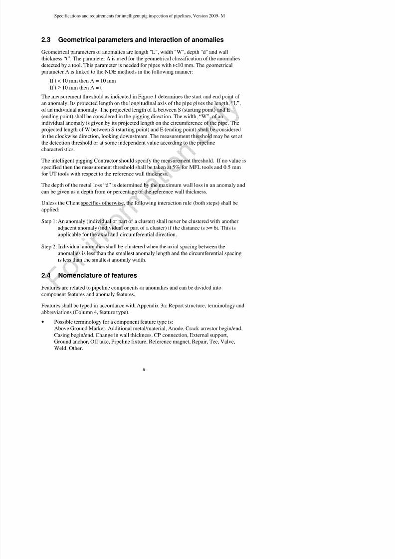
2.3 Geometrical parameters and interaction of anomalies
Geometrical parameters of anomalies are length "L", width "W", depth "d" and wall
thickness “t”. The parameter A is used for the geometrical classification of the anomalies
detected by a tool. This parameter is needed for pipes with t<10 mm. The geometrical
parameter A is linked to the NDE methods in the following manner:
If t < 10 mm then A = 10 mm
If t ≥ 10 mm then A = t
The measurement threshold as indicated in Figure 1 determines the start and end point ofan anomaly. Its projected length on the longitudinal axis of the pipe gives the length, “L”,
of an individual anomaly. The projected length of L between S (starting point) and E
(ending point) shall be considered in the pigging direction. The width, “W”, of an
individual anomaly is given by its projected length on the circumference of the pipe. The
projected length of W between S (starting point) and E (ending point) shall be considered
in the clockwise direction, looking downstream. The measurement threshold may be set at
the detection threshold or at some independent value according to the pipeline
characteristics.
The intelligent pigging Contractor should specify the measurement threshold. If no value is
specified then the measurement threshold shall be taken at 5% for MFL tools and 0.5 mm
for UT tools with respect to the reference wall thickness.
The depth of the metal loss “d” is determined by the maximum wall loss in an anomaly and
can be given as a depth from or percentage of the reference wall thickness.
Unless the Client specifies otherwise, the following interaction rule (both steps) shall be
applied:
Step 1: An anomaly (individual or part of a cluster) shall never be clustered with another
adjacent anomaly (individual or part of a cluster) if the distance is >= 6t. This is
applicable for the axial and circumferential direction.
Step 2: Individual anomalies shall be clustered when the axial spacing between the
anomalies is less than the smallest anomaly length and the circumferential spacing
is less than the smallest anomaly width.
2.4 Nomenclature of features

7/25/2019 POF Specs 2009-M
http://slidepdf.com/reader/full/pof-specs-2009-m 9/38
Specifications and requirements for intelligent pig inspection of pipelines, Version 2009- M
• Possible terminology for an anomaly feature type is:
Anomaly.
The type of features shall be further identified in accordance with Appendix 3a: Reportstructure, terminology and abbreviations (Column 5, feature identification).
• The component features typed as additional metal/material, repair and weld can be
further identified as:
Additional metal/material: Debris magnetic/non-magnetic, touching metal-to-metal,
other.
Repair: Welded sleeve begin/-end, Composite sleeve begin/-end, Weld deposit
begin/-end, Coating begin/-end, Other begin/-end.Weld: Bend begin / end, Change in diameter, Change in wall thickness, Adjacent
tapering, Longitudinal / Spiral / not identifiable seam, Seamless (If more features are
identified for one weld, then this shall be reported in the column “Comments”).
• The possible terminology for anomaly feature identification is:
Arc strike, Artificial defect, Buckle, Corrosion, Corrosion cluster, Crack, Dent, Dent
with metal loss, Gouging, Grinding, Girth weld crack, Girth weld anomaly, HIC,
Lamination, Longitudinal seam weld crack, Longitudinal weld anomaly, Ovality, Pipemill anomaly, Pipe mill anomaly cluster, SCC, Spalling, Spiral weld crack, Spiral
weld anomaly, Wrinkle, Other.
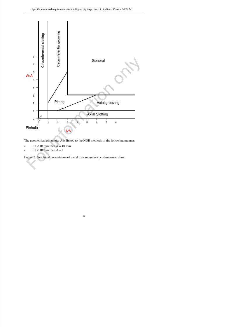
2.5 Metal loss anomaly classification
The measurement capabilities of non-destructive examination techniques depend on the
geometry of the metal loss anomalies. These metal loss anomaly classes have been defined
as shown in Figure 2 to allow a proper specification of the measurement capabilities of the
intelligent pig. Each anomaly class permits a large range of shapes. Within that shape a
reference point is defined at which the POD is specified.
Anomaly dimension class Definition Reference point/size
for the POD in terms
of L x W
General: {[W ≥ 3A] and [L ≥ 3A]} 4A x 4APitting: {([1A ≤ W < 6A] and [1A ≤ L < 6A]
and [0.5 < L/W < 2]) and not
([W ≥ 3A] and [L ≥ 3A])}
2A x 2A
Axial grooving: {[1A ≤ W < 3A] and [L/W ≥ 2]} 4A x 2A
i f i l
7/25/2019 POF Specs 2009-M
http://slidepdf.com/reader/full/pof-specs-2009-m 10/38
Specifications and requirements for intelligent pig inspection of pipelines, Version 2009- M
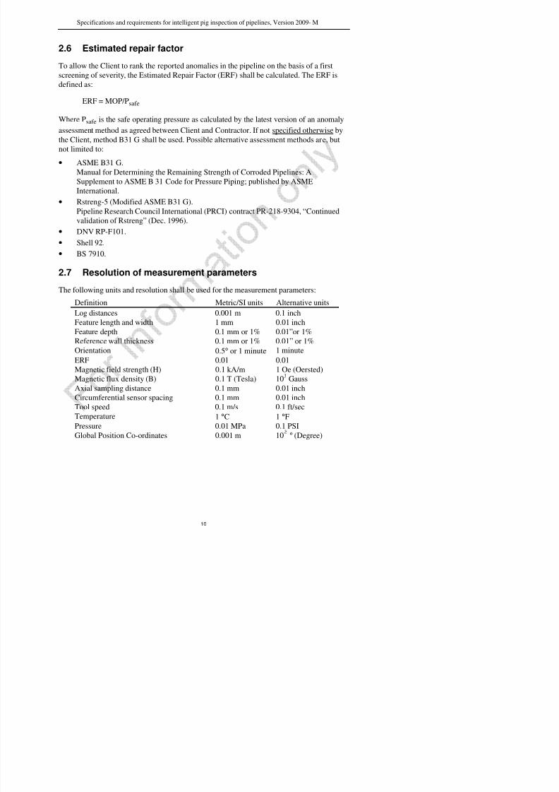
2.6 Estimated repair factor
To allow the Client to rank the reported anomalies in the pipeline on the basis of a first
screening of severity, the Estimated Repair Factor (ERF) shall be calculated. The ERF is
defined as:
ERF = MOP/Psafe
Where Psafe is the safe operating pressure as calculated by the latest version of an anomaly
assessment method as agreed between Client and Contractor. If not specified otherwise by
the Client, method B31 G shall be used. Possible alternative assessment methods are, butnot limited to:
• ASME B31 G.
Manual for Determining the Remaining Strength of Corroded Pipelines: A
Supplement to ASME B 31 Code for Pressure Piping; published by ASME
International.
• Rstreng-5 (Modified ASME B31 G).
Pipeline Research Council International (PRCI) contract PR-218-9304, “Continued
validation of Rstreng” (Dec. 1996).
• DNV RP-F101.
• Shell 92.
• BS 7910.
2.7 Resolution of measurement parametersThe following units and resolution shall be used for the measurement parameters:
Definition Metric/SI units Alternative units
Log distances 0.001 m 0.1 inch
Feature length and width 1 mm 0.01 inch
Feature depth 0.1 mm or 1% 0.01”or 1%
Reference wall thickness 0.1 mm or 1% 0.01” or 1%
Orientation 0.5° or 1 minute 1 minute
ERF 0.01 0.01
Magnetic field strength (H) 0.1 kA/m 1 Oe (Oersted)
Magnetic flux density (B) 0.1 T (Tesla) 103 Gauss
Axial sampling distance 0.1 mm 0.01 inch

7/25/2019 POF Specs 2009-M
http://slidepdf.com/reader/full/pof-specs-2009-m 11/38
Specifications and requirements for intelligent pig inspection of pipelines, Version 2009- M
3. Health and safety
Care for health and safety is essential during any stage of any activity. As intelligent
pigging of pipelines typically involves working with pressurized components and
potentially explosive and/or flammable environments, adequate procedures must be in
place to prevent any harm to personnel, environment or equipment. It is the responsibility
of both pipeline operator and (ILI) tool operator to agree on health and safety requirements
and procedures and to check if latest and most stringent versions of (local) HSE
requirements are met.
ILI operations require a pipeline to be opened and an inspection tool to be loaded/unloaded
whereby explosive environments might occur. Special measures to prevent unsafe
situations during ILI activities should be taken.
Regulations have been developed to prevent accidents due to explosive environments.
Examples of these regulations are the ATEX guideline (ATmosphères EXplosive,
European Union) or the NEC 505 (National Electrical Code 505, United States).
Implementation of ATEX, NEC 505 or an equivalent code might be mandatory on the basis
of local legislation or can be considered for ILI operations in addition to already applicable
standards and procedures. In this specification only ATEX requirements that relate to ILI
tools are considered, however it is not claimed that all requirements are covered.
For use of non-electrical equipment in potentially explosives atmospheres, EN13463 or an
equivalent standard can be applicable.
3.1 ATEX
The Client shall specify if the ATEX certification will be required and if applicable for the
ILI operations, then the following two directives need to be followed.
- ATEX 95* (Equipment Directive 94/9/EC), Design and operation of industrial
equipment and protective systems intended for use in potentially explosive
atmospheres.
Note: This directive implies hat the ILI vendor has to assess all potential explosion
risks of its equipment and has to design the equipment to this directive.
- ATEX 137* (Workplace Directive 99/92/EC), Organizational requirements for
health & safety protection of industrial workers at risk from potentially explosive

7/25/2019 POF Specs 2009-M
http://slidepdf.com/reader/full/pof-specs-2009-m 12/38
Specifications and requirements for intelligent pig inspection of pipelines, Version 2009- M
Zone 2: areas where one has to reckon with a dangerous explosive Atmosphere
caused by gas, vapour or mist occurring only rarely and then only for a
short time
Non-Hazardous Area: Procedure ensures that an explosive atmosphere will NOT
occur
ATEX 95 (equipment directive 94/9/EC)
The Client must assess the zone classification of the work environment. For ILI activities in
the oil and gas industry it is considered that, unless specific measures are taken, zone 1 is
typically applicable. If ATEX certification is required and unless the Client notifies
otherwise, it is considered that operating the intelligent pig requires ATEX certification for
the following conditions:
- Equipment group II (for use in explosive atmospheres)
- Equipment category 2 (high protection level for use in zone 1 & 2)
ATEX 137 (workplace directive 99/92/EC)
ATEX 137 gives organizational and operational requirements for activities in potentially
explosive environments. It is the responsibility of both Client and Contractor to define
operating procedures and work instructions to assure safe work environment. These
procedures are (except those related to zone classification, see above) considered outside
the scope of this document.
In addition to the ATEX requirements, which are only valid for atmospheric conditions, the
Client shall specify, whether the contractor shall ensure save operation of ILI equipment
under explosive conditions for pressures > 1.1 bar during receiving and launching of tools.
* Latest or superseding version shall be used
3.2 NEC 505
The National Electrical Code 505 is an adoption of ATEX and not further discussed in this
specification.
4. Tool specifications
4.1 General tool specifications
The most common tools for metal loss and crack inspection are based on the MFL or

7/25/2019 POF Specs 2009-M
http://slidepdf.com/reader/full/pof-specs-2009-m 13/38
Specifications and requirements for intelligent pig inspection of pipelines, Version 2009- M
The measurement specifications shall include the Tables 2 to 9 where they apply. If not
agreed otherwise between Client and Contractor, these specifications can be verified with
dig-up results, pull/pump test data or a combination thereof at a confidence level of 95%.
General tool specifications, valid for all tool types:
• Wall thickness range for full performance;
• Speed range for full performance;
• Number and type of defect detection and sizing sensors (or the circumferential
sample interval in case of a rotating sensor system);
• Axial sample interval, specify distance or frequency (time) controlled;• Nominal circumferential centre to centre distance of primary measuring sensors;
• Temperature range;
• Maximum pressure;
• Minimum pressure for operation;
• Minimum bend radius;
•
Minimum bend to bend distance;• Minimum distance between T-openings;
• Minimum internal diameter of straight pipe and bend sections;
• Tool length, weight and number of bodies;
• Differential pressure required to launch and run the tool;
• Maximum length of pipeline that can be inspected in one run (may be coupled to
max. operating time and condition of the pipeline;
• Minimum length for launcher;
• Minimum distance between receiver valve and reducer in the receiver;
• Indication of by pass flow in case of tool stuck.
4.2 MFL tool specifications
Based on the direction of magnetization, at least two types of tools are available. The
standard MFL tool that magnetises the pipe wall in the axial direction, has limitedsensitivity to axially aligned defects. MFL tools that magnetises the pipe wall in the
circumferential direction are more sensitive for axially aligned metal loss, but are likely to
have different specifications. If the specifications of more type of tools are requested, then
individual tables shall be supplied.
7/25/2019 POF Specs 2009-M
http://slidepdf.com/reader/full/pof-specs-2009-m 14/38
Specifications and requirements for intelligent pig inspection of pipelines, Version 2009- M
• Required minimal induced magnetic flux density B in Tesla in the pipe wall to meet
the given POD and accuracy.
• Nominal circumferential distance of ID/OD discriminating sensors (if present).• Location accuracy of the features with respect to the upstream girth weld, the
upstream marker and the orientation in the pipe.
The measurement specifications shall include the Tables 1 to 8 where they apply.
It is recognized that the probability of detection of a feature is highly dependent on several
factors such as pipe wall magnetization and signal noise (from sensor mechanical ride,
sensor noise, electronic noise, cleanliness etc.). Tables 2 and 3 shall therefore be linked tothe operating window of the tool (e.g. pipe wall magnetization range, tool velocity and also
to the pipe type (i.e. seamless pipe vs. seam-welded pipe).
If crack detection is possible and included in the inspection scope of work, the Contractor
shall provide the following parameters:
• Minimum depth, length and opening dimension of a crack to be detectable;
• The orientation limits (angle to pipeline axis) of cracks that can be detected;• The certainty level for the detection of this minimum crack;
• The accuracy of sizing of crack length and depth;
• The certainty level for the sizing performance.
4.3 UT tool specifications – metal loss detection
In addition to the general tool specifications, UT-metal loss detection tool specificationshall include:
• Nominal circumferential spacing of measuring sensors;
• Dimensions of UT transducers and diameter of crystal;
• Frequency of UT signal;
• Stand-off distance of UT transducers;
• Diameter* of UT beam (@ -6 dB) at the inner pipe surface and outer pipe surface.
* Diameter of sound beam where pressure is 6 dB below the pressure at the 0 dB
position.
The measurement specification shall include the Tables 1 to 8 where they apply.
7/25/2019 POF Specs 2009-M
http://slidepdf.com/reader/full/pof-specs-2009-m 15/38
Specifications and requirements for intelligent pig inspection of pipelines, Version 2009- M
In addition to the general specifications, UT-crack detection tool specifications shall
include, for all technologies:
• Crack depth and length detection threshold;
• The orientation limits (angle to pipeline axis) of cracks that can be detected;
• The certainty level for the detection of this minimum crack;
• The accuracy of sizing of crack length and depth;
• The certainty level for the sizing performance.
Complemented for conventional UT technology with:
• Nominal circumferential spacing of measuring sensors;
• Dimensions of UT transducers;
• Frequency of UT signal;
• Angle of UT signal in steel;
• Direction of angle of UT signal relative to pipe axis (longitudinal direction is 0º,
circumferential is 90º).
Complemented for phased array technology with:
• Number of phased array transducers;
• Number and dimensions of active elements within each transducer;
• Frequency of UT signal;
• Range of angles of UT signal that is generated in pipe wall;
• Direction of angle of UT signal relative to pipe axis (longitudinal direction is 0º,
circumferential is 90º).
Complemented for the EMAT technology with:
• Number of EMAT transducers (transmitter/receiver);
• Type, mode and frequency of ultrasonic signal generated.
The measurement specification shall include Tables 1 and 5.
4.5 Geometry tool specifications
Geometry tools can be used to detect and size geometrical internal anomalies. High
resolution geometry tools can be required to accurately size deformations or internal metal
losses to assess the integrity of the pipeline. The specifications below might be extended to

7/25/2019 POF Specs 2009-M
http://slidepdf.com/reader/full/pof-specs-2009-m 16/38
Specifications and requirements for intelligent pig inspection of pipelines, Version 2009- M
• Minimum/maximum ovality measurement dimension;
• Number of sensors recorded continuously;
• Presence and resolution of clock position indicator;• Location accuracy of the features with respect to the upstream girth weld, the
upstream marker and the log distance;
• Presence and number of independent girth weld detection sensors.
* Deformation includes dents, wrinkles, buckles.
The measurement specification shall include Tables 1 (where applicable), 6 and 8.
4.6 Mapping tool specifications
Pipeline mapping tools can be applied as a single inspection tool, but currently units are
often attached to an MFL or other inspection tool, whereby the inspection unit has a double
functionality. Specific post survey interpretation may also allow detecting and sizing of free
spans, landslides etc. The specifications of mapping equipment are quite different and
require a specific list.
The geographical location of features shall be expressed in GPS coordinates unless
specified otherwise by the Client.
The measurement specification shall include Table 1 (where applicable) and 9.
5. Personnel qualificationThe personnel operating the ILI systems and the personnel handling, analyzing and
reporting the inspection results shall be qualified and certified according to
ANSI/ASNT-ILI-PQ-2005 (or later version/superseding document).
Unless the Client specifies otherwise, key personnel shall meet the following minimum
qualifications (ref. ANSI/ASNT-ILI-PQ-2005):
• Team leader during ILI field activities: Level II Tool Operator for the applicable
technology.
• Data analysis and reporting: Level II Data Analyst for the applicable technology.
• Review of final Client report: Level III Data Analyst for the applicable technology.
The review should include (but not limited to) e g a quality check of data analysis

7/25/2019 POF Specs 2009-M
http://slidepdf.com/reader/full/pof-specs-2009-m 17/38
Specifications and requirements for intelligent pig inspection of pipelines, Version 2009- M
The final inspection report (hard & electronic copy) of either a single or combined ILI tool
run shall contain the following information and be available within 8 weeks of the ILI run
unless agreed otherwise:
• Field report
• Tool operational data
• Tool calibration
• Pipe tally
• List of anomalies
• List of clusters
• Summary and statistical data
• Fully assessed feature sheets
• Anomaly ranking method for ERF
• Detection of AGMs
More details on the required information are given below.
The list of anomalies and the pipe tally shall be compatible with standard CSV or DBF filescompatible with EXCEL files.
In addition to the hard copy a user friendly software package shall be provided to enable
review and assessment of the data collected by the inspection tool.
6.1 Field report
The field report shall contain a statement of the Contractor on the quality and findings ofall preparatory activities, tool runs and inspection run.
6.2 Tool operational data
The tool specifications shall be given. In addition the following operational data shall be
provided, whereby each type of tool that has been used shall be described separately:
• Data sheet of used tool(s) with e.g. serial number, software version etc.• The data-sampling frequency or distance
• The detection threshold
• The reporting threshold, normally taken at 90% POD if not specified otherwise
• A tool velocity plot over the length of the pipeline
7/25/2019 POF Specs 2009-M
http://slidepdf.com/reader/full/pof-specs-2009-m 18/38
Specifications and requirements for intelligent pig inspection of pipelines, Version 2009- M
Unless specified otherwise, the formulation for acceptable data loss for UT tools shall be:
The maximum acceptable sensor and/or data loss is 3% and the maximum allowable signal
loss due to other reasons (e.g. echo loss) is 5%, whereby continuous loss of data from more
than two adjacent transducers or 25 mm circumference (whichever is smallest) is not
acceptable.
For all technologies an alternative methodology can be to define data loss based on the
required POD of a specific defect like:
The POD of an anomaly with minimum dimensions for a minimum percentage of the
pipeline surface and pipeline length. E.g. an anomaly with L≥20 mm, W≥20 mm, d≥20%
(or d≥1 mm for UT) in the pipeline shall be detected with a POD≥90% for ≥ 97% of thepipeline surface and ≥ 97% of the pipeline length.
The tool operational data statement shall indicate whether the tool has functioned according
to specifications and shall detail all locations of data loss and where the measurement
specifications are not met. When the specifications are not met (e.g. due to speed
excursions, sensor/data loss), the number and total length of the sections shall be reported
with possible changes of accuracies and certainties of the reported results.
6.3 Tool calibration
The Contractor shall provide information regarding the calibration procedure and latest
calibration record of the tool. The procedure should give insight in, but not limited to: used
calibration features, linepipe material, wall thickness and manufacturing process, tool
velocity, date and frequency of calibration. For magnetic tools the calibration information
will include the tool speed and the measured magnetic field strength value with the position
where it was measured. In addition the Contractor shall supply a definition of which sizing
model and revision was used.
It can be considered that, for specific applications, specifications and/or defect geometries,
dedicated tool calibration can be performed (e.g. with spare project pipes), followed by a
modified interpretation/sizing model.
6.4 Pipe tally
The pipe tally shall be a listing of all pipeline component features and anomaly features and
be reported in accordance (including terminology) with the report structure as given in
7/25/2019 POF Specs 2009-M
http://slidepdf.com/reader/full/pof-specs-2009-m 19/38
Specifications and requirements for intelligent pig inspection of pipelines, Version 2009- M
• Nominal t (of each joint or pipeline component, between girth welds);
• Measured t* (see below);
• Reference t;• Length of anomaly/feature;
• Width of anomaly/feature;
• d/t in % for MFL and d in mm or inch for UT;
• Surface location: internal (INT), external (EXT), mid-wall (MID) or not applicable
(N/A), see Column 14, Appendix 3a, Report structure;
• GPS coordinates of features if geographical tool is used;
• ERF;
• Comments.
* If not specified otherwise by the Client, the average of the wall thickness
measurements of undiminished sections is regarded to be representative for the pipe
joint/component.
6.5 List of anomalies
All anomalies with dimensions above the reporting threshold at 90% POD or above a
reporting threshold as specified by the Client shall be reported in the List of anomalies (see
also Appendix 3c, Report structure, Example List of Anomalies).
The list of anomalies shall contain the same fields as the pipe tally. The field “Feature
type” refers to anomalies, while the field “Feature identification” specifies these anomalieswith one of the following possible items (see Appendix 3a: Report structure,
Columns 4 and 5):
Arc strike, Artificial defect, Buckle, Corrosion, Corrosion cluster, Crack, Dent, Dent with
metal loss, Gouging, Grinding, Girth weld crack, Girth weld anomaly, HIC (hydrogen
induced cracking), Lamination, Longitudinal seam weld crack, Longitudinal weld anomaly,
Ovality Pipe mill anomaly, Pipe mill anomaly cluster, SCC (Stress Corrosion Cracking),
Spalling, Spiral weld crack, Spiral weld anomaly, Wrinkle, Other.
The List of Anomalies shall contain the clusters (according to Chapter 2.3) and the not-
clustered (individual) anomalies. Additionally the individual anomalies forming the
reported cluster (see Chapter 2.3) shall be listed in the final inspection report whereby the
relation between the anomalies and clusters are indicated (e.g. numbered).
7/25/2019 POF Specs 2009-M
http://slidepdf.com/reader/full/pof-specs-2009-m 20/38
Specifications and requirements for intelligent pig inspection of pipelines, Version 2009- M
6.7 Summary and statistical report
6.7.1 Summary and statistical report of metal loss tools
The summary report of metal loss tools shall contain a listing of:
• Total number of anomalies;
• Number of internal anomalies;
• Number of external anomalies;
• Number of general anomalies;
• Number of pits;
• Number of axial and circumferential grooves;
• Number of anomalies with depth 0 – <10%t;
• Number of anomalies with depth 10 – <20%t;
• Number of anomalies with depth 20 – <30%t;
• Number of anomalies with depth 30 – <40%t;
• Number of anomalies with depth 40 – <50%t;
• Number of anomalies with depth 50 – <60%t;
• Number of anomalies with depth 60 – <70%t;
• Number of anomalies with depth 70 – <80%t;
• Number of anomalies with depth 80 – <90%t;
• Number of anomalies with depth 90 - 100%t;
• Number of anomalies with ERF 0.6 – <0.8;• Number of anomalies with ERF 0.8 – <0.9;
• Number of anomalies with ERF 0.9 – <1.0;
• Number of anomalies with ERF ≥ 1.0.
If requested by the Client, the following histograms shall be provided over appropriate
section lengths of the pipeline (lengths of appropriate sections to be agreed between
Contractor and Client):• Number of anomalies in sections with depth < 0.4t;
• Number of anomalies in sections with depth 0.4t – <0.6t;
• Number of anomalies in sections with depth 0.6t – <0.8t;
• Number of anomalies in sections with depth ≥0 8t;
7/25/2019 POF Specs 2009-M
http://slidepdf.com/reader/full/pof-specs-2009-m 21/38
Specifications and requirements for intelligent pig inspection of pipelines, Version 2009- M
6.7.2 Summary and statistical report of geometry tools
The summary report of geometry tools shall contain a listing of:
• Total number of dents;
• Total number of ovalities;
• Number of dents with depth 2 – <6% ID;
• Number of dents with depth ≥ 6% ID;
• Number of ovalities* 0.10 > ratio < 0.05;
• Number of ovalities* with ratio ≥ 0.10;
• Orientation plot of all dents over the full pipeline length;
• Orientation plot of all ovalities over the full pipeline length.
* For applied definition of ovality see Table 6. By agreement between Client and
Contractor another definition and/or reporting windows can be specified.
6.8 Fully assessed feature sheets (dig-up sheets)
Unless specified otherwise, fully assessed feature sheets shall be provided for the ten most
serious indications. Selection of the most serious indications can be based on depth or
pressure, to be defined in Technical Scope of Work in the Contract. If not specified
otherwise, the selection of five anomalies will be depth based and the other five pressure
based. By agreement between Contractor and Client the selection can be based on ERF.
Fully assessed feature sheets shall contain the following information to the full sizing
specification:
• Length of pipe joint and (when present) orientation of longitudinal or spiral seam at
start and end of every joint;
• Length and longitudinal or spiral seam orientation of the 3 upstream and 3
downstream neighbouring pipe joints;
• Log distance of metal loss feature;
• Wall thickness of the pipe joints (up to the 3 upstream and 3 downstream joints);
• Log distance of features (with location coordinates known by Client) like magnet
markers, fixtures, steel casings, tees, valves, etc on the first three upstream and
downstream pipe joints;
• Distance of upstream girth weld to nearest, second and third upstream marker;

7/25/2019 POF Specs 2009-M
http://slidepdf.com/reader/full/pof-specs-2009-m 22/38
Specifications and requirements for intelligent pig inspection of pipelines, Version 2009- M
6.9 Anomaly ranking method for ERF
The estimated repair factor for anomalies shall be reported on the basis of the assessment
method indicated in Chapter 2.6.
6.10 Detection of AGMs
AGMs or reference magnets that have been positively identified during the ILI run shall be
indicated in the pipe tally. In addition, in the final inspection report the total number of
installed AGMs and the number of identified AGMs shall be reported.
Table 1: Identification of features
Feature Yes
POI>90%
No
POI<50%
May be
50%<=POI<=90%
Int. / ext. / mid wall discrimination
Additional metal / material:
- debris, magnetic
- debris, non-magnetic
- touching metal to metal
- Other
Anode
Anomaly:
- arc strike
- artificial defect
- buckle
- corrosion
- corrosion cluster
- crack
S ifi ti d i t f i t lli t i i ti f i li V i 2009 M

7/25/2019 POF Specs 2009-M
http://slidepdf.com/reader/full/pof-specs-2009-m 23/38
Specifications and requirements for intelligent pig inspection of pipelines, Version 2009- M
- lamination
- longitudinal weld crack
- longitudinal weld anomaly
- ovality
- pipe mill anomaly
- pipe mill anomaly cluster
- SCC
- spalling
- spiral weld crack
- spiral weld anomaly
- wrinkle
Crack arrestor
Eccentric pipeline casing
Change in wall thickness
CP connection / anode
External support
Ground anchor
Off take
Pipeline fixture
Reference magnet
Repair:
- welded sleeve repair
- composite sleeve repair
Specifications and requirements for intelligent pig inspection of pipelines Version 2009 M

7/25/2019 POF Specs 2009-M
http://slidepdf.com/reader/full/pof-specs-2009-m 24/38
Specifications and requirements for intelligent pig inspection of pipelines, Version 2009- M
- adjacent tapering
- longitudinal weld
- spiral weld
- not identifiable seam
- seamless
Table 2: Detection and sizing accuracy for metal loss anomalies in body of pi pe
General
metal-loss
Pitting Axial
grooving
Circumf.
grooving
Pinhole* Axial
slotting*
Circumf.
Slotting*
Depth at POD=90%
Depth sizing accuracy
at 80% certainty
Width sizing accuracy
at 80% certainty
Length sizing accuracy
at 80% certainty
Table 3: Detection and sizing accuracy for metal loss anomalies in weld or HAZ
General
metal-loss
Pitting Axial
grooving
Circumf.
grooving
Pinhole* Axial
slotting* Circumf.
Slotting*
Depth at POD=90%
Depth sizing accuracy
at 80% certainty
Width sizing accuracy
at 80% certainty
Length sizing accuracy
at 80% certainty
Specifications and requirements for intelligent pig inspection of pipelines Version 2009 M
7/25/2019 POF Specs 2009-M
http://slidepdf.com/reader/full/pof-specs-2009-m 25/38
Specifications and requirements for intelligent pig inspection of pipelines, Version 2009- M
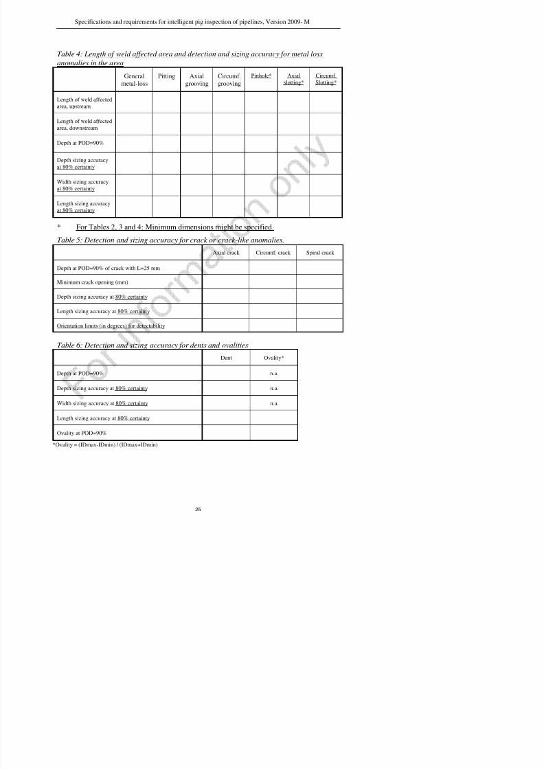
Table 4: Length of weld affected area and detection and sizing accuracy for metal loss
anomalies in the area
General
metal-loss
Pitting Axial
grooving
Circumf.
grooving
Pinhole* Axial
slotting* Circumf.
Slotting*
Length of weld affected
area, upstream
Length of weld affected
area, downstream
Depth at POD=90%
Depth sizing accuracy
at 80% certainty
Width sizing accuracy
at 80% certainty
Length sizing accuracyat 80% certainty
* For Tables 2, 3 and 4: Minimum dimensions might be specified.
Table 5: Detection and sizing accuracy for crack or crack-like anomalies.
Axial crack Circumf. crack Spiral crack
Depth at POD=90% of crack with L=25 mm
Minimum crack opening (mm)
Depth sizing accuracy at 80% certainty
Length sizing accuracy at 80% certainty
Orientation limits (in degrees) for detectability
Table 6: Detection and sizing accuracy for dents and ovalities
Dent Ovality*
Depth at POD=90% n.a.
Specifications and requirements for intelligent pig inspection of pipelines Version 2009- M

7/25/2019 POF Specs 2009-M
http://slidepdf.com/reader/full/pof-specs-2009-m 26/38
Specifications and requirements for intelligent pig inspection of pipelines, Version 2009 M
Table 7: Detection and sizing accuracy in 90º bends.
Minimal bend radius for detection of metal loss anomalies as given in Table 2 D*
Minimal bend radius for sizing accuracy for metal loss anomalies as given in Table 2 D*
Minimal bend radius for detection of crack or crack-like anomalies as given in Table 5 D*
Minimal bend radius for sizing accuracy of crack or crack-like anomalies as given in Table 5 D*
* If the bend radius in the pipeline is smaller than given in the table, then applicable specifications for that bend radius shall
additionally be provided in the form of Tables 2 or 5.
Table 8: Location accuracy of features.
Accuracy of distance to upstream girth weld at 90% certainty
Accuracy of distance from pig trap valve at 90% certainty
Accuracy of circumferential position at 90% certainty
Table 9: Horizontal and vertical accuracy of pipeline location as function of marker
distance and certainty.
Marker distance (m)
(add rows to table if required)
Horizontal accuracy (m)
at 80% certainty
Vertical accuracy (m)
at 80% certainty
0.5 0.5
1.0 1.0
2.0 2.0
Specifications and requirements for intelligent pig inspection of pipelines, Version 2009- M
7/25/2019 POF Specs 2009-M
http://slidepdf.com/reader/full/pof-specs-2009-m 27/38
p q g p g p p p ,
Figure 1: Location and dimensions of metal loss anomaly.
Specifications and requirements for intelligent pig inspection of pipelines, Version 2009- M
7/25/2019 POF Specs 2009-M
http://slidepdf.com/reader/full/pof-specs-2009-m 28/38
p q g p g p p p
0
1
2
3
5
6
7
8
4
0 1 2 3 4 5 6 7 8
Axial Slotting
Axial groovingPitting
Pinhole
General
L/A
W/A
The geometrical parameter A is linked to the NDE methods in the following manner:
• If t < 10 mm then A = 10 mm
• If t ≥ 10 mm then A = t
Figure 2: Graphical presentation of metal loss anomalies per dimension class.
Specifications and requirements for intelligent pig inspection of pipelines, Version 2009- M

7/25/2019 POF Specs 2009-M
http://slidepdf.com/reader/full/pof-specs-2009-m 29/38
Appendix 1: Operator’s guideline for defining specific details ofthe POF specifications
Introduction
The POF document “Specifications and requirements for intelligent pig inspection of
pipelines” gives an outline of advised specifications for In-Line-Inspection (ILI) of
pipelines. The Client (pipeline owner) might adapt certain specification to reflect the
Client’s specific requirements. For certain aspects of the inspection and/or reporting
requirements however, some options are already considered and the document gives theopportunity/requirement to define specific items. This guideline is intended to support the
Client by listing the considered optional items in the specifications that can or should be
defined prior to sending the specifications to the ILI company.
In addition, in this guideline also some notes and advised specifications are given ( printed
in Italic), like the minimum requirements that are regarded essential for a successful ILI
run.
Chapter 2.3 – Geometrical parameters and interaction of anomalies
A default interaction rule is specified, but another rule can be specified if required.
Chapter 2.6 - Estimated Repair Factor
The ASME B31.G methodology is specified as the default assessment method for the ERF
calculation, but another methodology can be specified if required.
Note:
- The ASME B31G is commonly used
- The Rstreng method asks for a detailed anomaly profile, which hardly can be provided by
present ILI tools. The application of the Rstreng method is more focussed on the detailed
measurements based on verification.
Chapter 2.7 – Measurement parameters
The Client shall specify if metric or alternative units shall be used.
Chapter 3.1 – ATEX
The Client shall specify if ATEX certification is required and if so, assess the zone
classification.
Specifications and requirements for intelligent pig inspection of pipelines, Version 2009- M
7/25/2019 POF Specs 2009-M
http://slidepdf.com/reader/full/pof-specs-2009-m 30/38
The typical minimal detectable defect depth of a UT tool is 1 to 1.5 mm with a POD of
90%.
Depth, length and width sizing accuraciesThe accuracy depends on the anomaly dimension class:
Typical for (high resolution) MFL tools: depth 10-15% t, length and width accuracy 10-
20 mm.
Typical for UT tools: depth 0.3 – 0.5 mm, length and width accuracy 10 mm.
For anomaly depth, length and width sizing accuracy, the typical certainty level is 80%.
Accuracy of distance and orientation (clock position) of features:
Typical accuracy of distance to/from marker: 0.25% of distance
Typical accuracy of distance to closest weld: 0.15 m.
Typical accuracy of circumferential position: 10°.
Geometry tool specification, reporting threshold:
The reporting threshold of the geometry tool for dents and ovalities shall be defined.
Typical reporting thresholds: dents: = 2 % pipeline ID and for ovalities = 5% pipeline
ID.
Certainty and accuracy of sizing deformations by geometry tool:
The certainties and accuracies of reported dents and ovalities shall be defined.
Typical certainties and accuracies are:
Ovalities: ID reduction, accuracy 1% of pipeline ID with certainty = 80%.
Length, accuracy 10% of pipeline ID with certainty = 80%.
Dents: Depth, accuracy 1% of pipeline ID with certainty = 80%.
Length, accuracy 10% pipeline ID with certainty = 80%.
Width, accuracy 10% pipeline ID with certainty = 80%.
Chapter 4.1 – General tool specifications
ILI companies are requested to supply measurement specification in tables 2 to 9. It is
stated that, as a default situation, these specifications can be verified via tests and at a
confidence level of 95%. However, it can be agreed to use different defect verification
methods and also different confidence levels (e.g. 99%, 90%, 80%).
Chapter 4.2 – MFL tool specifications
ILI companies are requested to supply technical information for review. Below a reference
value is given that relates to magnetic properties for MFL inspection.
Specifications and requirements for intelligent pig inspection of pipelines, Version 2009- M

7/25/2019 POF Specs 2009-M
http://slidepdf.com/reader/full/pof-specs-2009-m 31/38
As the magnetisation level also is a function of the tool velocity (especially at high
velocity) and location in the pipe wall (relevant for external corrosion in thick walled
pipes), the Client is given the option to request magnetisation data at the outer pipe surface
for the applicable tool velocity.
Chapter 4.6 - Mapping tool specifications
Geographical locations shall be reported in GPS coordinates by default, but another method
can be specified if required.
Chapter 5 – Personnel qualification
Minimum requirements for qualifications of key personnel are given but can be specified
otherwise by the Client.
Chapter 6 – Reporting requirements
The typical contents of the final inspection is given and the maximum time frame for the
availability of the final inspection report is stated to be 8 weeks after the ILI run. This time
frame is regarded a typical and acceptable period, but a different time frame and different
report contents can be agreed between parties.
Chapter 6.2 - Tool operational data
By default, the reporting threshold is specified at 90% POD, but can be specified otherwise.
Note: the reporting threshold for metal loss corrosion defects is typically 10% t and
normally taken at 90% POD. For special detailed information (e.g. corrosion growth
calculation) 5% and for inspection special focussed on FFP or detection of special
threats: 15 or 20%.
A default formulation for acceptable data loss is specified, but another methodology can be
specified if required.
Note: For sensor and/or data loss of magnetic and UT tools two possibilities are given.
Other formulation of maximum data/sensor loss might be more applicable for specific
situations.
Chapter 6.4. – Pipe tally
The standard definition for average pipe wall thickness is stated as representative for the
pipe joint/component, but the client can specify another definition.
Chapter 6.7.1 - Summary and statistical report of metal loss tools
Specifications and requirements for intelligent pig inspection of pipelines, Version 2009- M
7/25/2019 POF Specs 2009-M
http://slidepdf.com/reader/full/pof-specs-2009-m 32/38
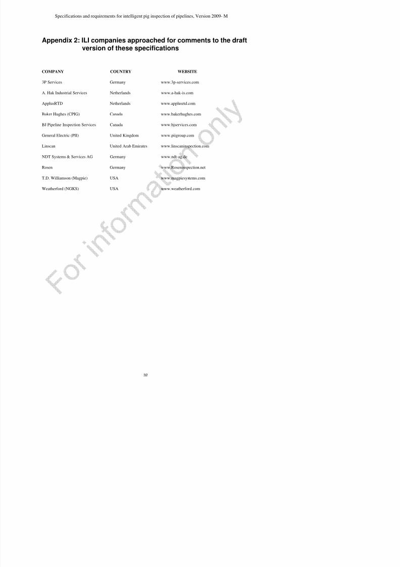
Appendix 2: ILI companies approached for comments to the draftversion of these specifications
COMPANY COUNTRY WEBSITE
3P Services Germany www.3p-services.com
A. Hak Industrial Services Netherlands www.a-hak-is.com
ApplusRTD Netherlands www.applusrtd.com
Baker Hughes (CPIG) Canada www.bakerhughes.com
BJ Pipeline Inspection Services Canada www.bjservices.com
General Electric (PII) United Kingdom www.piigroup.com
Linscan United Arab Emirates www.linscaninspection.com
NDT Systems & Services AG Germany www.ndt-ag.de
Rosen Germany www.Roseninspection.net
T.D. Williamson (Magpie) USA www.magpiesystems.com
Weatherford (NGKS) USA www.weatherford.com
Specifications and requirements for intelligent pig inspection of pipelines, Version 2009- M
7/25/2019 POF Specs 2009-M
http://slidepdf.com/reader/full/pof-specs-2009-m 33/38
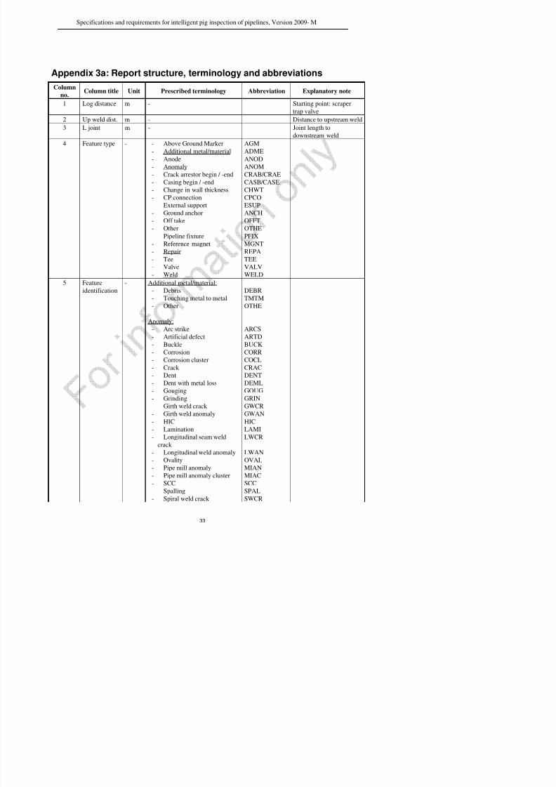
Appendix 3a: Report structure, terminology and abbreviationsColumn
no.Column title Unit Prescribed terminology Abbreviation Explanatory note
1 Log distance m - Starting point: scraper
trap valve
2 Up weld dist. m - Distance to upstream weld
3 L joint m - Joint length to
downstream weld
4 Feature type - - Above Ground Marker- Additional metal/material
- Anode
- Anomaly
- Crack arrestor begin / -end
- Casing begin / -end
- Change in wall thickness
- CP connection
- External support
- Ground anchor- Off take
- Other
- Pipeline fixture
- Reference magnet
- Repair
- Tee
- Valve
- Weld
AGMADME
ANOD
ANOM
CRAB/CRAE
CASB/CASE
CHWT
CPCO
ESUP
ANCHOFFT
OTHE
PFIX
MGNT
REPA
TEE
VALV
WELD
5 Feature
identification
- Additional metal/material:
- Debris
- Touching metal to metal
- Other
Anomaly:
- Arc strike
- Artificial defect
- Buckle- Corrosion
- Corrosion cluster
- Crack
- Dent
- Dent with metal loss
Gouging
DEBR
TMTM
OTHE
ARCS
ARTD
BUCKCORR
COCL
CRAC
DENT
DEML
GOUG
Specifications and requirements for intelligent pig inspection of pipelines, Version 2009- M

7/25/2019 POF Specs 2009-M
http://slidepdf.com/reader/full/pof-specs-2009-m 34/38
- Spiral weld anomaly
- Wrinkle
- Other
Repair:
- Welded sleeve begin / -end
- Composite sleeve begin / -
end
- Weld deposit begin / -end
- Coating begin / -end
- Other begin / -end
Weld:-
- Bend begin / -end
- Change in diameter
- Change in wall thickness
- Adjacent tapering
- Longitudinal seam- Spiral seam
- Not identifiable seam
- Seamless
SWAN
WRIN
OTHE
WSLB/WSLE
CSLB/CSLE
WDPB/WDPE
COTB/COTE
OTHB/OTHE
BENB/BENE
CHDI
CHWT ADTA
LOSESPSE
NISE
SMLS
No abbreviation for all
welds different from
welds below
Applicable for: Pipe –
pipe unequal WT
6 Feature class - Axial Grooving
- Axial Slotting
- Circumferential Grooving
- Circumferential Slotting
- General- Pinhole
- Pitting
AXGR
AXSL
CIGR
CISL
GENEPINH
PITT
See Fig. 2
7 Clock
position
h:min See Fig. 1
8 Nominal t mm Nominal wall thickness of
every joint
9 Reference t mm The actual not diminished
wall thickness
surrounding a feature10 Length mm Anomaly length in axial
direction
11 Width mm Anomaly width in
circumferential direction
12 d (peak) % Peak depth % of ref t or
Specifications and requirements for intelligent pig inspection of pipelines, Version 2009 - M
7/25/2019 POF Specs 2009-M
http://slidepdf.com/reader/full/pof-specs-2009-m 35/38
35
Appendix 3b: Report structure, Example pipe tallyLog distance
(m)
Up weld
dist. (m)
L joint
(m)
Feature type
(Component and Anomaly)
Feature identification
(Component and Anomaly)
Anomaly
Dimension
class
Clock
position
h:min
Nominal t
(mm)
Measured/
Reference
t (mm)
Length
(mm)
Width
(mm)
d (peak)
% (MFL)
mm (UT)
d (mean)
% (MFL)
mm (UT)
Surface
loc.
GPS ERF Comments
11158.682 - 15.38 Weld (WELD) Longitudinal seam (LOSE) - - 14.3 14.8- - - - - - - -
11161.334 2.65 -Above Ground Marker
(AGM)- - - 14.3 14.8 - - - - - - AGM nr. 6
11163.581 4.90 - Anomaly (ANOM) Gouging (GOUG) CIGR 10:28 14.3 14.8 23 254 28 16 EXT - -
11165.903 7.22 - Anomaly (ANOM) Corrosion cluster (COCL) GENE 5:12 14.3 14.8- 392 188 17 11 EXT 0.94 -
11174.067 - 12.16 Weld (WELD)Change in wall thickness
(CHWT)- - 12.4 12.9 - - - - - - -
11175.285 1.22 - Anomaly (ANOM) Dent (DENT) - 0:18 12.4 13.0 - - - - - - 2.5 % Dent depth
11177.467 3.40 - Anomaly (ANOM)Dent with metal Loss
(DEML)- 12:08 12.4 13.0 112 7 16 9 - - 5.5 % Dent depth
1178.969 4.90 - Anomaly (ANOM)Pipe mill anomaly cluster
(MIAC)GENE 10:15 12.4 13.0 401 889 25 12 INT - -
11183.152 9.09 - Anomaly (ANOM) Pipe mill anomaly (MIAN) CIGR 6:12 12.4 13.0 17 55 15 9 EXT - -
11183.324 9.26 - Casing begin (CASB) - - - 12.4 13.0 - - - - - - Mainstreet11185.968 11.90 - Casing end (CASE) - - - 12.4 13.0 - - - - - - -
11186.222 - 12.48 Weld (WELD) Longitudinal seam (LOSE) - - 12.4 13.0 - - - - - - -
11187.978 1.75 - Anomaly (ANOM)Longitudinal weld anomaly
(LWAN)PITT 2:09 12.4 12.9 39 26 15 8 EXT - -
11198.701 - 12.56 Weld (WELD)Change in wall thickness
(CHWT)- - 11.2 11.9 - - - - - - Seamless (SMLS)
11198.701 0.00 - Anomaly (ANOM) Girth weld anomaly (GWAN CIGR 4:06 11.2 11.9 14 131 10 6 N/A - -
111202.352 3.65 - Anomaly (ANOM) Grinding (GRIN) CIGR 6:6 11.2 11.9 16 43 16 4 EXT - -
11203.013 4.31 - Additional metal / material(ADME)
Touching metal to metal(TMTM)
- 1:46 11.2 11.9 - - - - - - -
11211.267 - 3.00 Weld (WELD) Spiral seam (SPSE) - - 20.4 - - - - - - Installation S114-01
11212.769 1.50 Tee (TEE) - - 3:00 20.4 - - - - - - Installation S114-01
11214.263 - 3.50 Weld (WELD) Spiral seam (SPSE) - - 30.8 - - - - - - Installation S114-01
11216.015 1.75 Valve (VALV) - - 12:00 30.8 - - - - - - Installation S1140
11217.767 - 2.20 Weld (WELD) Bend begin (BENB) - - 18.2 - - - - - - - Installation S1140
Specifications and requirements for intelligent pig inspection of pipelines, Version 2009 - M

7/25/2019 POF Specs 2009-M
http://slidepdf.com/reader/full/pof-specs-2009-m 36/38
36
Appendix 3b: Report structure, Example pipe tallyLog distance
(m)
Up weld
dist. (m)
L joint
(m)
Feature type
(Component and Anomaly)
Feature identification
(Component and Anomaly)
Anomaly
Dimension
class
Clock
position
h:min
Nominal t
(mm)
Measured/
Reference
t (mm)
Length
(mm)
Width
(mm)
d (peak)
% (MFL)
mm (UT)
d (mean)
% (MFL)
mm (UT)
Surface
loc.
GPS ERF Comments
11219.965 - 12.54 Weld (WELD) Bend end (BENE) - - 11.2 11.9 - - - - - - Installation S1140
11232.502 - 13.02 Weld (WELD) Not identifiable seam (NISE) - - 11.2 11.9 - - - - - - -
11232.758 0.25 - Anomaly (ANOM) Corrosion (CORR) PITT 6:11 11.2 11.9 10 17 17 11 EXT 0.91 -
11245.521 - 12.30 Weld (WELD) Not identifiable seam (NISE) - - 11.2 11.9 - - - - - - -
11257.822 - 11.20 Weld (WELD) Bend begin (BENB) - - 11.2 12.7 - - - - - - -
11269.026 - 12.04 Weld (WELD) Bend end (BENE) - - 11.2 12.7 - - - - - - -
11281.064 - 12.09 Weld (WELD) Not identifiable seam (NISE) - - 11.2 11.9 - - - - - - -
11292.613 11.55 - Repair (REPA) Welded sleeve begin (WSLB) - - 11.2 11.9 - - - - - - -
11293.062 12.00 - Anomaly (ANOM) Corrosion (CORR) CIGR 7:09 11.2 11.9 23 65 13 11 EXT 0.91 -
11293.154 - 12.54 Weld (WELD) Not identifiable seam (NISE) - - 11.2 11.9 - - - - - - -
11293.311 0.16 - Anomaly (ANOM) Corrosion (CORR) AXGR 6:23 11.2 11.9 126 16 21 12 EXT 0.94 -11293.383 0.23 - Anomaly (ANOM) Corrosion (CORR) GENE 8:12 11.2 11.9 36 40 17 12 EXT 0.91 -
11293.670 0.52 - Repair (REPA) Welded sleeve end (WSLE) - - 11.2 11.9 - - - - - - -
11305.697 - 12.54 Weld (WELD) Not identifiable seam (NISE) - - 11.2 11.9 - - - - - - -
Specifications and requirements for intelligent pig inspection of pipelines, Version 2009 - M
7/25/2019 POF Specs 2009-M
http://slidepdf.com/reader/full/pof-specs-2009-m 37/38
37
Appendix 3c: Report structure, Example list of anomalies
Log distance
(m)
Up weld
dist. (m)
L joint
(m)
Anomaly
Feature type
Anomaly Feature
identification
Anomaly
Dimension
class
Clock
position
h:min
Nominal
t (mm)
Measured
/
Reference
t (mm
Length
(mm)
Width
(mm)
d (peak)
% (MFL)
mm (UT)
d (mean)
% (MFL)
mm (UT)
Surface
loc.GPS ERF Comments
11163.581 4.90 -Anomaly
(ANOM)Gouging (GOUG) CIGR 10:28 14.3 14.8 23 254 28 16 EXT - -
11165.903 7.22 -Anomaly
(ANOM)
Corrosion cluster
(COCL)GENE 5:12 14.3 14.8 392 188 17 11 EXT 0.94 -
11175.285 1.22 - Anomaly(ANOM) Dent (DENT) - 0:17 12.4 13.0 - - - - - - 2.5 % Dent depth
11177.467 3.40 -Anomaly
(ANOM)
Dent with metal Loss
(DEML)- 12:01 12.4 13.0 112 7 16 9 - - 5.5 % Dent depth
11178.969 4.90 -Anomaly
(ANOM)
Corrosion cluster
(COCL)GENE 10:15 12.4 13.0 401 889 25 12 INT - -
11183.152 9.09 -Anomaly
(ANOM)
Pipe mill anomaly
(MIAN)CIGR 6:13 12.4 13.0 17 55 15 9 EXT - -
11187.978 1.75 -Anomaly
(ANOM)
Longitudinal weld
anomaly
(LWAN)
PITT 2:09 12.4 12.9 39 26 15 8 EXT - -
11198.701 0.00 -Anomaly
(ANOM)
Girth weld anomaly
(GWAN)CIGR 4:08 11.2 11.9 14 131 10 6 N/A - -
111202.352 3.65 -Anomaly
(ANOM)Grinding (GRIN) CIGR 6:31 11.2 11.9 16 43 16 4 EXT - -
11232.758 0.25 -Anomaly
(ANOM)Corrosion (CORR) PITT 6:11 11.2 11.9 10 17 17 11 EXT 0.91 -
11293.062 12.00 -Anomaly
(ANOM)Corrosion (CORR) CIGR 7:08 11.2 11.9 23 65 13 11 EXT 0.91 -
11293.311 0.16 -Anomaly
(ANOM)
Pipe mill anomaly Cluster
(MIAC)AXGR 6:04 11.2 11.9 126 16 21 12 EXT 0.94 -
11295.383 0.23 -Anomaly
(ANOM)Corrosion (CORR) GENE 8:19 11.2 11.9 36 40 17 12 EXT 0.91 -
Specifications and requirements for intelligent pig inspection of pipelines, Version 2009 - M

7/25/2019 POF Specs 2009-M
http://slidepdf.com/reader/full/pof-specs-2009-m 38/38
38
Appendix 3d: Report structure, example list of clusters
Log distance (m)Up weld dist.
(m)
Anomaly Feature
identification
Clock
position
h:min
Nominal t
(mm)
Measured
or
Reference
t (mm)
Length
(mm)
Width
(mm)
d (peak)
% (MFL)
mm (UT)
d (mean)
% (MFL)
mm (UT)
Surface location Comments
11165.903 4.900 Corrosion cluster 4 10:28 14.3 345 240 28 16 EXT -
11165.903 4.900 Corrosion 10:57 14.3 39 178 17 11 EXT -
11166.013 5. 013 Corrosion 10:28 14.3 232 180 28 18 EXT
11178.969 3.400 Corrosion cluster 5 1:01 12.4 601 389 26 18 EXT
11178.969 3.400 corrosion 1:50 12.4 306 267 26 10 EXT -
11179.303 3.642 corrosion 2:10 12.4 167 80 16 12 EXT -
11179.562 5.40 corrosion 3:31 12.4 200 229 13 9 EXT -
11179.969 3.908 corrosion 1:01 12.4 35 100 18 11 EXT -
11293.315 0.162 Pipe mill anomaly cluster
4
6:04 11.2 126 160 21 12 EXT -
11293.315 0.162 pipe mill anomaly 7:09 11.2 90 39 16 11 EXT -
11293.369 0.216 pipe mill anomaly 6:04 11.2 52 100 19 12 EXT
11293.375 0.222 pipe mill anomaly 7:04 11.2 66 89 21 18 EXT