pocket zone field manual - faro technologies inc. · pdf file · 2013-06-10using...
TRANSCRIPT

Pocket Zone Field Guide This guide will help you get started using Pocket Zone with your laser device in the field. Not all information relating to Pocket Zone is covered in this guide. You should review your Pocket Zone printed manual for more program information.
Install Pocket Zone Current handheld computers are operating under Microsoft’s Pocket PC operating system. Note: The current Recon’s also run with Pocket PC and the installation selection for the Recon actually installs the general version of Pocket Zone.
More info More information relating to Pocket Zone can be found in the Pocket Zone section of the Discussion Groups at www.cadzone.com.
Backup your Pocket PC
ALERT: DATA LOSS on Pocket PC's What can cause loss of data on your Pocket PC: 1) Dead battery. 2) Removing battery. 3) Hard Re-boot. How do you backup your Pocket PC data and programs: Your Pocket PC is not like your desktop or laptop computer in the sense that drawings saved under My Documents will not be saved if your Pocket PC has power failure...UNLESS you perform a "Backup Now" or "Sprite Backup" before a power failure occurs. The backup tools are found in the Programs directory of your Pocket PC. WITH THE NEWER WINDOWS MOBILE 5 & 6 OPERATING SYSTEMS BACKUPS are automatic so there is NO SPRITEBACK UP function. You can still save the job ion the memory and then do a “SAVE AS” to make a copy on the flash secure memory. But be sure to ALWAYS go back and work in the one stored in the regular RAM MEMORY and not off the storage card or it is be very slow. If you are swapping BATTERIES on your Pocket PC be sure to backup the unit BEFORE pulling out the battery.
1

NOTE: Using the backup feature on your Pocket PC will save the Pocket Zone program and access key to run the fully licensed Pocket Zone.
When should you "BACKUP" your Pocket PC: 1) After installing Pocket Zone and setting up your Pocket PC. 2) After updating, installing a new version of Pocket Zone. 3) After creating a diagram in Pocket Zone. 4) Before changing batteries on your Pocket PC. Safe places to SAVE your work: I) “Built in Storage" is a folder on your Pocket PC that is actually "FLASH" memory and is non-volatile. You can save you work there and it will remain there even in the event of a total power loss to the system. Note: While shooting, the drawing should be saved to Main Memory. Do NOT set up Pocket Zone to save to a memory card while shooting. If you shoot a drawing that's saving to the Storage Card your system will slow down considerably. Storage Cards are too slow to save to while shooting. II) You can insert "Memory Cards" such as Sandisk cards into your Pocket PC and save work to that location. These are the same cards used in digital cameras to save more pictures.
2

Set up and Level your Laser Device Level the tri-brach (screws to the tripod; the total station clips into it) while it's on the tripod. Put one foot on the foot of the leg of the tripod before loosening it to adjust its height. Adjust and grip the leg above the joint to maintain max control. Get the bubble somewhere inside the ring - doesn't have to be perfectly centered. Now you're ready to level the instrument. Turn the face so it is parallel to any two thumbscrews. Turn the screws equal but opposite of one another (simultaneously) until the bubble on the instrument is centered. Finally, turn the instrument 90 degrees so the face is parallel to the remaining thumbscrews. Turn only that one thumbscrew until the bubble is centered. There you have it.
Mark Station Location Using the optical, laser, or string plummet put in a P-K nail (and washer) in the ground to mark the station location. The job of pounding in P-K nails into the street can be made easier and simpler by using a 2lb sledge and vice grips to hold onto the nail. (TIP: Some people use washers with the nails or paint over the nails for easier relocation.)
3

Establishing a Reference (Zero) Point From the station location (P-K nail) run a tape out 30' to 50' in the direction of your zero set (North). At the end of the tape place another P-K nail (and washer). Note: Establishing a fixed reference point serves three purposes.
a) Verify the accuracy of the first shot taken by measuring the shot on the Pocket Zone screen and comparing that value and direction with the actual (tape measured) point.
b) At the end of shooting the scene you can shoot the initial reference point again. This last shot should land very close to the initial reference shot. This will establish the accuracy of your shoot. This is very beneficial if you’ve moved the laser device during the shoot and what to verify accuracy was maintained.
c) If the laser device was bumped, moved, knocked over, or shutdown, you would have to setup and reinitialize the system. You can continue shooting in your current drawing by leveling and centering the laser device over the established station point and zero set off of the existing reference point. This will put you back in your existing diagram and allow you to continue shooting.
4

Zero Set the Laser Device Zero set the laser device along the same line as the tape. Refer to the documentation for your specific laser device for zero set instructions. Note: Nikon drivers prompt the user to "Point Device to Diagram Top". When the user clicks OK the Nikon total station zero sets itself in the direction the device is pointing.
Start Pocket Zone With the Pocket PC connected to the laser device, run Pocket Zone. From the opening screen enter a file name. Set to Feet or Meters. Pick a Description file (Police or Fire). Click OK.
5

Pick your Laser Device Driver From the File menu select "Laser Device" and pick the driver for your device. Note: Your communication settings on your laser device must match the driver settings in Pocket Zone. Most likely, the Pocket Zone settings will coincide with the settings on your device. Refer to the documentation for your specific laser device for comm. setting instructions.
Set Instrument and Reflector Height After selecting your laser driver you will be prompted to set the instrument height and reflector height. If you have set up your laser device to shoot in "reflector-less" mode then un-check “Use Reflector” box.
6

Instrument Height The height (offset from the ground to the lens) of the total station is taken into consideration when the shot is taken. This offset is subtracted from the shot, making the reference point at ground level. Use Reflector If the “Use Reflector” box has been checked and the reflector height set correctly, the height of the reflector will also be subtracted from the shot. Reflector-less If the “Use Reflector” box is un-checked then the shot will take as is. For example, if you shot a six foot height reflector and the “Use Reflector” box was un-checked you would be adding six feet to the overall elevation of the shot.
Note: You do not need to re-select your device driver to switch between reflector and reflector-less mode. If you're using a reflector-less system and switching between reflector and reflector-less mode during the shooting of your scene, be sure to check or un-check the “Use Reflector” box in the "Instrument Settings" dialog.
7

Take your First Shot Take your first shot to the end of the tape (nail) along your zero set line. This will give you a good test shot for distance and direction and will allow you to set up the station at that same location at a later time. Shooting a Total Station You can fire your total station by clicking on the Fire button in Pocket Zone. When the driver has been selected the Fire button will turn from grey to red.
You can also fire the total station from your Pocket PC keypad. On an IPAQ you press the middle of the rocker button to fire the total station. From a pocket pc with built in keypad or Windows buttons you can press the Enter key to fire the total station.
8

IMPORTANT! Shooting an Impulse Laser (LTI, Laser Atlanta, Contour) If you’re shooting with an impulse laser such as an LTI device you’ll have to fire the impulse manually. The Fire button will NOT turn red in Pocket Zone when one this type
f device is selected.
layed on e screen. Point 1 is the instrument location and point 2 is the first target shot.
o The First Shot! When the first shot is fired and accepted by Pocket Zone two points will be dispth
Listen to Pocket Zone When you fire your total station from Pocket Zone you should hear a “laser” sound effect. If you don’t hear anything or it’s too low adjust the volume on your pocket pc.When Pocket Zone accepts the shot data from the laser device you will hear another “success” sound. Once you’re accustomed to these sounds they will help you in the fieldto determine if you got a good shot or not. If you don’t hear the “success” sound or you hear something different you may have an err
or on your laser device or something else idn’t allow Pocket Zone to accept the shot.
d
Measure between Points 1 and 2
d to measure between any two points. All pertinent easurement data will be displayed.
case you re questioned in court as to the accuracy and calibration of your instrument.
Use the “Measure Distance” commanm IMPORTANT TIP: Measure set up to reference shot MANUALLY with a tape or wheel and confirm distance measured with PocketZone. Make a note of this in a
9

Continue Shooting the Scene Add Descriptions Descriptions are used to label the shots taken at the scene. Depending on the description selected, it could also be assigned a color, layer, layer name, symbol, or line type. (SEE SECTION #17 at end for making new and customizing the description list!) Choose a description from the pull-down list of descriptions. Note: It is NOT necessary to pick the Point feature to shoot a point.
Note: The description is NOT reset back to "No Desc" after shooting a point. Don’t forget to change your description to a new description or "No Desc" when required.
10

Shoot Lines, Arcs, or Curves Pocket Zone is a combination data collection program and mini-cad program. Think of the laser device as your mouse. Instead of point and click, you point and shoot. You can shoot multiple points and then connect the points with a continuous line, curve, 3pt arc, or single line (2pt line). You can select the line, arc, or curve before shooting and then take your shots. The shot points will be displayed as well as the geometry. Single Line: Line is complete after the second shot. 3 Point Arc: Arc is complete after the third shot. Continuous Line: Line is complete only when you click on the “OK” button. Curve: Curve is complete only when you click on the “OK” button.
Display (Remove the Clutter) Each shot taken can be represented by a point, point number, elevation, and symbol. During the course of a normal shoot the display would easily become too cluttered to work with. You can hide these different objects by opening the “Display Options” dialog and un-checking the items to hide.
11
Save your Work You can save your work by clicking on the “disk” icon at the bottom of the screen or selecting the Save feature from the File menu. Auto Save If you haven’t taken a shot for 60 seconds the program will automatically save your current work to a bak file. You will not be able to take another shot until the save is complete. After each save a backup file of the previous save is created with a bak extension. This is a backup of your work in case something happens to corrupt the main file. You still should click the disk icon or Save when done. To close out of the job click the File menu and then EXIT. The “x” at the top right only minimizes so the job is still open. Point List and RAW data- we recommend you save both with the PZD file: Once your work is complete you should also save the data in your file into other formats. From the File menu you can select “Save Point List….” to generate an ASCII file of all of your shot points. The point list is saved in the format, Point Number, North, East, Elevation, and Description. This is in a simple txt file format and you can select to have it as space or tab delimited You can also save the RAW data by selecting “Create RAW Data File” feature. This feature saves in the same format as the point list, plus it appends the raw data to each shot as it was gathered from the laser device. Get into the practice of saving both the TXT and RAW file along with the original PZD file. These should be saved along with your completed CZD (CAD Zone Drawing) file and all part of your case file. These files may be requested in a court case. Importing into a Diagram Program The Pocket Zone file is saved with a .pzd (Pocket Zone drawing) extension. This file type can be opened up directly into programs by The CAD Zone. The pzd file contains the mapped information and also the encrypted raw data. A pzd file saved to your desktop or laptop can be uploaded back into your data collector. This allows you to add missed data, used to generate a raw or coordinate point lists or resize the text size if needed. If you need to save the PocketZone file format that can be read by other diagram programs you can also save your file as an AutoCAD .dwg or .dxf file type.
12

From the Pocket PC to your Desktop Computer Regardless of the type of pocket pc you’re using it will have some method of synching (connecting) to your main computer. It may be a cradle that connected to your computer that the pocket pc rests in or a simple serial cable from the pocket pc to your computer. Once connected, Microsoft’s Active Sync program is the software used to connect the two devices. Once connected open up Windows Explorer (File Manager) to copy the Pocket Zone file to your desktop computer. By default, the Pocket Zone .pzd files are saved to the Diagrams folder on your pocket pc. From you pocket pc, copy the .pzd file to your diagrams folder on your desktop computer. Open up Crash Zone, File Open, choose .pzd as your file type, select and open the .pzd file. Once opened in the diagram program it becomes a .czd file (cad zone diagram). The first time it’s saved it will be saved with the .czd extension. This method leaves the .pzd file intact and un-edited to maintain integrity of the collected evidence. Sync PDA to Desktop
a) Plug the USB cable into PDA (or put PDA in cradle). b) You should see the Active Sync icon on the task bar (bottom right of computer screen) turn green and spin. c) A screen called “Set up a Partnership” will appear, or show up on the task bar. d) Choose the NO radio button, it’s NOT necessary to set up a partnership to sync the two devices and it is best not to do it since it may start to download other data. e) Choose Next and the Active Sync dialogue box will appear telling you that you are connected. f) Minimize the Active Sync dialog.
Find your Pocket Zone Diagram
g) Right click on the My Computer icon on your screen or the Start button at the bottom left of your screen and choose Explore. h) Find the Mobile Device folder. i) Click on Mobile Device. (You are now looking at the files on the PDA and NOT the desktop computer). j) Click on the plus sign to the left of Mobile Device (this will expand the folder tree for the PDA). k) Click on plus sign to the left of My Computer. This will expand the folder tree for My Computer on the PDA. l) Click on the plus sign to the left of My Documents. m) Click on the Diagrams folder. This is the location of all pzd files created on the pocket pc.
13

Move the Pocket Zone Diagram to the Desktop Computer
n) Select the diagram(s) you want to copy to the desktop computer. o) Hold your stylus down on the selected diagram(s) and don’t let up until the copy / paste menu pops up. Select Copy from this menu. p) Paste the diagram(s) into the folder which you have designated for storing your Crash Zone drawings on your desktop computer. q) Open up Crash Zone. Click Open from the File pull-down menu. r) Select .pzd as your file type. r) Locate the .pzd file. q) Double click on that file and it will open in Crash Zone. r) Work on diagram. s) Save the drawing. It will automatically be saved with the .czd extension.
Tips Handwriting Recognition Transcriber is the handwriting recognition software on your Pocket PC. You might find using the transcriber method faster than hunting for keys on the on-screen keyboard. Transcriber can be activated by selecting the up-arrow next to the input selection icon (looks like a keyboard) at the bottom of the screen and choosing Transcriber. Once Transcriber is initiated it puts down an icon that looks like a hand holding a pencil. Examples for using Transcriber:
a) Quick Description Selection. Click on the Description pull down list. Anywhere on your screen, handwrite the first letter or letters of the description you want and let up with the stylus. The list will automatically move to descriptions beginning with that letter or letters.
b) Place Text. Start the Text command. Click once in the text entry box to start a flashing cursor. Handwrite your text notes. Click in the text size box and change your text size. Backspace over the existing value and write in another.
c) More Examples. Enter your file name when starting Pocket Zone or saving a file. Add Notes to an object by selecting it with the Object Info command.
14
Set Up in an Existing Scene (.pzd file) Working from the First Total Station Reference Point You may have to set up your laser device and pocket zone to work with a scene you’ve been shooting or recently shot. This could happen for a number of reasons. You left the scene and have returned for more data or something happened to the equipment that requires you to set up again. If you established an instrument location point (PK nail or other marker) and you established your first shot point as a zero reference point you can work in the existing drawing. Set up and level the instrument over the first point. Zero set the instrument on the second point established earlier when the job was first started. Start Pocket Zone and open the current job. Select your “laser device” driver. Set your instrument height settings to reflect the new settings. Because you’re setup on the reference point previously established in the Pocket Zone drawing and you zero set the instrument in the same direction previously used you can start shooting new points in the old drawing. Be sure to shoot a couple of previously shot points to verify the new shots are accurate (they should fall on top of very close to the old shots). 3 Pt Locate and Reposition The 3Pt Locate and Repositioning command is located on the File menu in Pocket Zone. By setting up the total station anywhere in the previously shot scene you can re-establish yourself back in an existing file by shooting three previously shot points while clicking on the same point in the Pocket Zone diagram. See the Pocket Zone manual for more information on this feature. Merge Multiple Pocket Zone files in Crash Zone You can create multiple Pocket Zone drawings from a single scene. You might want to shoot the roadway and save it, start a new file, and shoot the crashed vehicles from the same scene and save them as well. Open up the first file (roadway) in Crash Zone, then, use the Merge feature to bring in the second file (vehicles). Both files need to have at least two points in common to be accurately aligned to each other. See the “Align Common Points” documentation in the on-line help in the diagram program.
Troubleshooting
a) Before running Pocket Zone close out all other programs and reset the pocket pc. This will ensure there is sufficient memory.
b) The pocket pc should be connected and turned ON before turning on the total station.
15

c) If you need to stop shooting for a while and you want to save battery power on your pocket pc you can power down while still in Pocket Zone. Do NOT exit out of Pocket Zone or you’ll have to re-open the drawing and re-establish the total station location in the drawing. Simply POWER DOWN and do not exit the job so it will keep your current set up location. If you need to re-establish the position of the total station within the drawing refer to the notes in Step 14 above.
d) If you’re having communication problems between Pocket Zone and your laser device try clicking the “Reset COM Port” command on the File menu.
e) Shots out of sync: If you have trouble getting a shot and then the next shot is placed in the previous shot's location you should reselect the laser device driver. Reselecting the driver will not screw up your current station location. You can also try clicking the “Reset COM Port” command on the File menu.
f) Units on your total station should match units you're using in Pocket Zone (Feet or Meters). Check both the total station settings and Pocket Zone settings.
g) Data Send Failed: If you get a "Data Send Failed" error message in Pocket Zone when trying to take a shot it means the com port on the Pocket PC is not active. 1) Reset the pocket pc. 2) Run Pocket Zone and re-select the laser device driver. 3) If you try to start a new file while shooting in Pocket Zone you have to re-select the laser device driver. Closing Pocket Zone or selecting "New" will disengage the com port.
h) More Communication Trouble: 1) You may have software that's clogging up the com port such as an external keypad program? If so, you need to open the keyboard software and click the "disable" box. 2) Make sure you've selected the correct driver for your laser device. 3) Make sure the communication settings on the laser device match the driver settings. 4) Make sure you cable is plugged in correctly. Check your connections for bent prongs. 5) Start up and zero set the laser device, connect the Pocket PC and run Pocket Zone.
Pocket Cross Section Mode What is “Cross Section”? Cross Section mode allows you to shoot points out of order, while automatically drawing a line, arc, or curve, between points with like descriptions. Regardless of the sequence in which you shoot the points, lines, arcs, or curves are automatically connected between points with the same description. This following example is a simple roadway created with Cross Section mode. The shots were taken top to bottom, from left to the right. EP1, at the top left of the drawing, was
16

shot first, then CL1 below it, and EP2 below that. Then, moving to the right, EP2 was shot, then CL1, then up to EP1; continuing until the roadway was completed.
The Selected line, arc, or curve is automatically drawn between points with the same description as the shots are taken. If Cross Section was not being used, all of the EP1 shots would need to be taken in sequence to connect a line or curve between them. In Cross Section mode the selected tool (a line, arc, etc.) remains active until you click “OK”, or until you exit Cross Section mode. Upon exiting, Cross Section automatically finishes any continuous lines or curves that are active.
Using Cross Section Mode To record data in Cross Section mode:
1) Click on the “Cross Section Mode” button.
17

2) Pick a description from the Cross Section pull-down list.
Note: You cannot use the standard description pull-down list while in Cross Section mode. The standard list remains grayed out until you close Cross Section. Active Code [x] The Cross Section description list displays an [x] next to any active, unfinished description that has not been completed by clicking OK. For instance, if two shots were recorded using the EP1 description and OK was not pressed, an [x] appears next to the EP1 description on the pull-down menu. The [x] indicates the EP1 sequence is still active, but allows you to record other data shots without affecting EP1 data.
18

3) Select the drawing entity (line, arc, or curve, etc.) you want drawn between the points with the selected description. Don’t select an entity if you just wish to shoot points. You do not need to select the Point command when recording data points with the data collector; only select Point when you are manually placing points in the drawing.
Note: A single line will only connect between two points and then finish. An arc will only connect between three points and then finish. You can change the entity connected to a specific description by selecting a different entity at the beginning of the next shot. You will be prompted whether or not you want the new entity to begin from the last point. For example, this allows you to change from a line to a curve along a stretch of road, creating a smoother transition in the drawing.
4) When finished shooting in Cross Section mode, click the Cross Section mode button. Cross Section closes, and any unfinished lines and curves with the same description will automatically be completed. Consecutively, Cross Section descriptions with an active [x] code are automatically completed.
Customizing Your Cross Section Description List The Cross Section Description List can be customized by editing the “CrossSections.txt” file located in the Pocket Zone directory on your Pocket PC. The Cross Section description file differs from the standard descriptions, in that there is no description added to the text line. For example, in Standard Descriptions “Edge of Pavement would appear like so:
EP1,Edge Pavement, Layer=12, Layer=Scene, color=0, linetype=solid
19

The same description is entered in Cross Section like this:
EP1, Layer=12, Layer=Scene, color=0, linetype=solid You can add Cross Section descriptions at any time using the “Custom” feature on the Cross Section pull-down list. The order of the descriptions in your list mirrors the order the list as it was created in the text file. The following is an example of a CrossSections.txt file:
CL1, Layer=12, Layer=Scene, color=0, linetype=solid CL2, Layer=12, Layer=Scene, color=0, linetype=solid CL3, Layer=12, Layer=Scene, color=0, linetype=solid CL4, Layer=12, Layer=Scene, color=0, linetype=solid CL5, Layer=12, Layer=Scene, color=0, linetype=solid CL6, Layer=12, Layer=Scene, color=0, linetype=solid DL, Layer=12, Layer=Scene, color=0, linetype=cz2_skid_4 EP1, Layer=12, Layer=Scene, color=0, linetype=solid EP2, Layer=12, Layer=Scene, color=0, linetype=solid FL1, Layer=12, Layer=Scene, color=0, linetype=solid FL2, Layer=12, Layer=Scene, color=0, linetype=solid JB, Layer=12, Layer=Scene, color=0, linetype=solid MED1, Layer=12, Layer=Scene, color=0, linetype=solid MED2, Layer=12, Layer=Scene, color=0, linetype=solid RRT1, Layer=12, Layer=Scene, color=0, linetype=cz1_rxr RRT2, Layer=12, Layer=Scene, color=0, linetype=cz1_rxr YL1, Layer=12, Layer=Scene, color=0, linetype=solid
Pocket Description List Customization
PocketZone comes with some default description libraries that you pick from when mapping a crash or crime scene. You access these under the “Description List” on the PocketZone opening screen. You can customize or add description libraries to incorporate your own familiar codes. Setting up a good description library will save you hours and perhaps days of drawing time! It looks complex at first but it is easy to do. PocketZone comes with default libraries of descriptions for Police and Fire. You can modify and RENAME so you have your very own. Some of the ones included as defaults are: 1.) _Police.Txt : a generic default library for crash or crime 2.) Accident_Recon.txt : geared for crash investigation
20
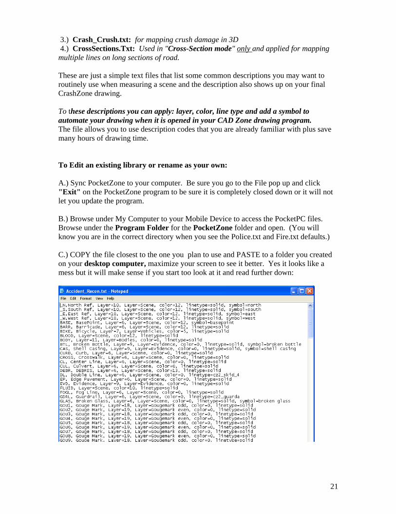
3.) Crash_Crush.txt: for mapping crush damage in 3D 4.) CrossSections.Txt: Used in "Cross-Section mode" only and applied for mapping multiple lines on long sections of road. These are just a simple text files that list some common descriptions you may want to routinely use when measuring a scene and the description also shows up on your final CrashZone drawing. To these descriptions you can apply: layer, color, line type and add a symbol to automate your drawing when it is opened in your CAD Zone drawing program. The file allows you to use description codes that you are already familiar with plus save many hours of drawing time. To Edit an existing library or rename as your own: A.) Sync PocketZone to your computer. Be sure you go to the File pop up and click "Exit" on the PocketZone program to be sure it is completely closed down or it will not let you update the program. B.) Browse under My Computer to your Mobile Device to access the PocketPC files. Browse under the Program Folder for the PocketZone folder and open. (You will know you are in the correct directory when you see the Police.txt and Fire.txt defaults.) C.) COPY the file closest to the one you plan to use and PASTE to a folder you created on your desktop computer, maximize your screen to see it better. Yes it looks like a mess but it will make sense if you start too look at it and read further down:
21

22
To apply layers, colors and other attributes - this editing and set up must be done on your desktop and then the file copied to the PocketZone program on the PocketPC device. D.) See the seven optional fields described below to understand your choices and make the setting you like. Once completed be sure to save and make a back-up. The txt file allows you to preset many features so when you download to CrashZone (drawing program) much of your drawing is done for you. An hour or two of planning can save hundreds of hours over a year: It is just a simple comma delimited file that allows you to define the: 1.) description that appears on drawing (Do Not use spaces in the description names) 2.) expanded description - for your reference only 3.) select layer number 4.) assign a text name to that layer number 5.) assign a color (references color selection in CrashZone) * 6.) assign a line type (references line types in CrashZone) * 7.) assign a symbol (references symbol pallet in CrashZone) * *TIP: to find You can use lines and symbols in the CrashZone drawing program and if you select that line or symbol and type “oi” it will come up with Object Info and tell you the name of the line type or symbol so you know what to use when customizing. E.) Now copy your revised the .txt file to your Pocket PC device in the PocketZone program folder. (You will know you are in the correct directory when you see the Police.txt and Fire.txt defaults.) You can overwrite one of the defaults by using the same name or better yet, choose your name or agency name for easier reference. Be sure you have used the File menu and select Exit if you had PocketZone open previously or you cannot make any changes or updates. F.) Now when you open a new job in PocketZone, on the screen you put in your File Name just under "Units" there is a pull-down that lets you pick from Police or Fire defaults. If you added your own file name, it will appear as one of the options. IMPORTANT RULES: Pocket Zone doesn't like spaces in the description name. For example for Tire Mark 1 use "TM1" and not "TM 1". Do not put non-numeric and stay with alpha characters and numbers only. Do not start layer names with numbers and if you want to use numbers, do so only after alpha characters. DO A BACK UP of this custom description list file on your computer too as a precaution if you PocketPC dies for any reason.
Copyright, 2007 - The Cad Zone, Inc. - Beaverton, OR - All Rights Reserved