pneumatic nozzle flapper control of an array of … nozzle flapper control of an array of...
TRANSCRIPT
Pneumatic Nozzle Flapper Control of an
Array of Cantilevers Using a
Single Thermal MicroActuator
Murad Abu-Khalaf
Instructors: Professor Edward S. Kolesar, Texas Christian University
Professor Frank L. Lewis, The University of Texas at Arlington
ABSTRACT
In this work, a Pneumatic Nozzle Flapper is built and simulated. This device is used to stimulate a mechanical force that is applied at the same time to an array of cantilevers that needs to be pushed mechanically. A thermal microactuator functions as a flapper for the pneumatic system allowing same amount of force to be applied at the same time to all cantilevers. Simulation shows that the idea is feasible and can work at the micro scale. Finite Element Analysis is provided for the pneumatic structure and the electrothermal microactuator.
INTRODUCTION
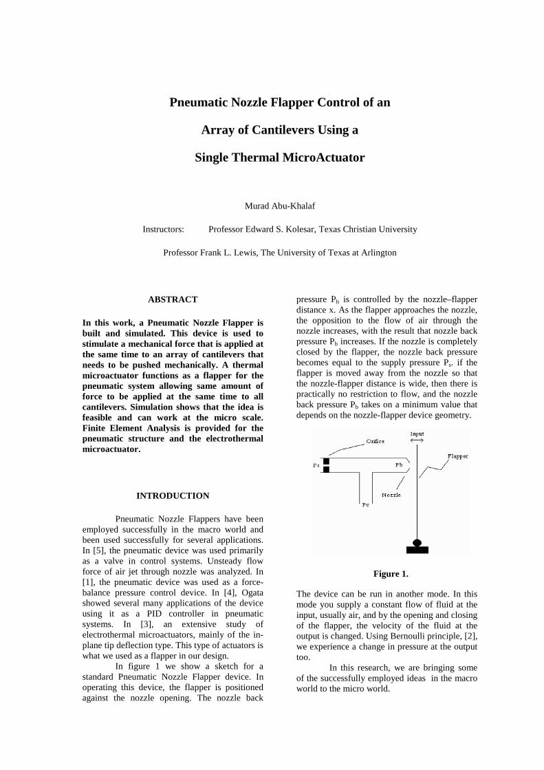
Pneumatic Nozzle Flappers have been employed successfully in the macro world and been used successfully for several applications. In [5], the pneumatic device was used primarily as a valve in control systems. Unsteady flow force of air jet through nozzle was analyzed. In [1], the pneumatic device was used as a force-balance pressure control device. In [4], Ogata showed several many applications of the device using it as a PID controller in pneumatic systems. In [3], an extensive study of electrothermal microactuators, mainly of the in-plane tip deflection type. This type of actuators is what we used as a flapper in our design. In figure 1 we show a sketch for a standard Pneumatic Nozzle Flapper device. In operating this device, the flapper is positioned against the nozzle opening. The nozzle back
pressure Pb is controlled by the nozzle–flapper distance x. As the flapper approaches the nozzle, the opposition to the flow of air through the nozzle increases, with the result that nozzle back pressure Pb increases. If the nozzle is completely closed by the flapper, the nozzle back pressure becomes equal to the supply pressure Ps. if the flapper is moved away from the nozzle so that the nozzle-flapper distance is wide, then there is practically no restriction to flow, and the nozzle back pressure Pb takes on a minimum value that depends on the nozzle-flapper device geometry. The device can be run in another mode. In this mode you supply a constant flow of fluid at the input, usually air, and by the opening and closing of the flapper, the velocity of the fluid at the output is changed. Using Bernoulli principle, [2], we experience a change in pressure at the output too. In this research, we are bringing some of the successfully employed ideas in the macro world to the micro world.
Figure 1.
Microelectromechanical systems fabrication technology (MEMS) allows building such devices in the micro world. The device we are to show in the next section was designed with features that are applicable to surface-micromachining fabrication processes. MUMPS process would suffice for this design. Several software packages were used to simulate the MUMPS process and to make the design process easier and more interactive. The main packages used were MEMSPRO, IntelliSuite.
DEVICE THEORY AND DESIGN
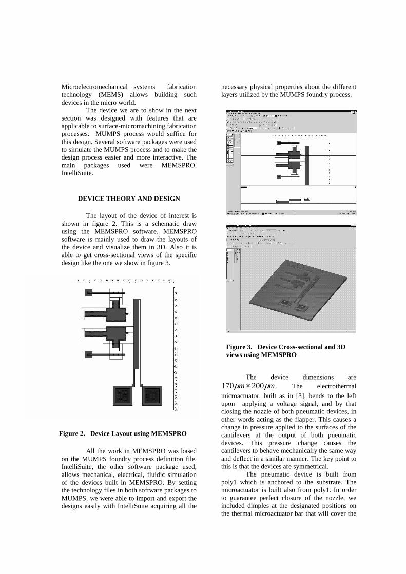
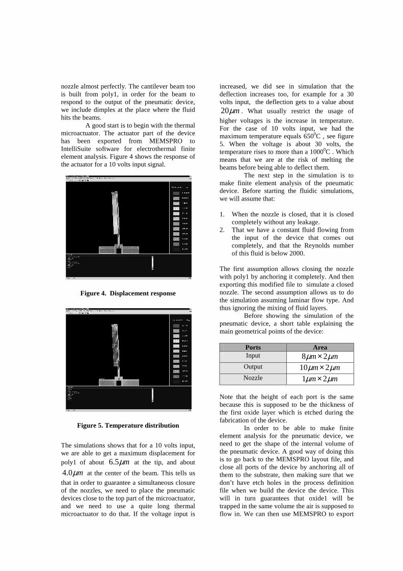
The layout of the device of interest is shown in figure 2. This is a schematic draw using the MEMSPRO software. MEMSPRO software is mainly used to draw the layouts of the device and visualize them in 3D. Also it is able to get cross-sectional views of the specific design like the one we show in figure 3.
All the work in MEMSPRO was based
on the MUMPS foundry process definition file. IntelliSuite, the other software package used, allows mechanical, electrical, fluidic simulation of the devices built in MEMSPRO. By setting the technology files in both software packages to MUMPS, we were able to import and export the designs easily with IntelliSuite acquiring all the
necessary physical properties about the different layers utilized by the MUMPS foundry process. The device dimensions are
mm µµ 200170 × . The electrothermal
microactuator, built as in [3], bends to the left upon applying a voltage signal, and by that closing the nozzle of both pneumatic devices, in other words acting as the flapper. This causes a change in pressure applied to the surfaces of the cantilevers at the output of both pneumatic devices. This pressure change causes the cantilevers to behave mechanically the same way and deflect in a similar manner. The key point to this is that the devices are symmetrical.
The pneumatic device is built from poly1 which is anchored to the substrate. The microactuator is built also from poly1. In order to guarantee perfect closure of the nozzle, we included dimples at the designated positions on the thermal microactuator bar that will cover the
Figure 2. Device Layout using MEMSPRO
Figure 3. Device Cross-sectional and 3D views using MEMSPRO
nozzle almost perfectly. The cantilever beam too is built from poly1, in order for the beam to respond to the output of the pneumatic device, we include dimples at the place where the fluid hits the beams. A good start is to begin with the thermal microactuator. The actuator part of the device has been exported from MEMSPRO to IntelliSuite software for electrothermal finite element analysis. Figure 4 shows the response of the actuator for a 10 volts input signal. The simulations shows that for a 10 volts input, we are able to get a maximum displacement for poly1 of about mµ5.6 at the tip, and about
mµ0.4 at the center of the beam. This tells us
that in order to guarantee a simultaneous closure of the nozzles, we need to place the pneumatic devices close to the top part of the microactuator, and we need to use a quite long thermal microactuator to do that. If the voltage input is
increased, we did see in simulation that the deflection increases too, for example for a 30 volts input, the deflection gets to a value about
mµ20 . What usually restrict the usage of
higher voltages is the increase in temperature. For the case of 10 volts input, we had the maximum temperature equals 6500C , see figure 5. When the voltage is about 30 volts, the temperature rises to more than a 10000C . Which means that we are at the risk of melting the beams before being able to deflect them. The next step in the simulation is to make finite element analysis of the pneumatic device. Before starting the fluidic simulations, we will assume that: 1. When the nozzle is closed, that it is closed
completely without any leakage. 2. That we have a constant fluid flowing from
the input of the device that comes out completely, and that the Reynolds number of this fluid is below 2000.
The first assumption allows closing the nozzle with poly1 by anchoring it completely. And then exporting this modified file to simulate a closed nozzle. The second assumption allows us to do the simulation assuming laminar flow type. And thus ignoring the mixing of fluid layers.
Before showing the simulation of the pneumatic device, a short table explaining the main geometrical points of the device:
Ports Area Input mm µµ 28 ×
Output mm µµ 210 ×
Nozzle mm µµ 21 ×
Note that the height of each port is the same because this is supposed to be the thickness of the first oxide layer which is etched during the fabrication of the device. In order to be able to make finite element analysis for the pneumatic device, we need to get the shape of the internal volume of the pneumatic device. A good way of doing this is to go back to the MEMSPRO layout file, and close all ports of the device by anchoring all of them to the substrate, then making sure that we don’ t have etch holes in the process definition file when we build the device the device. This will in turn guarantees that oxide1 will be trapped in the same volume the air is supposed to flow in. We can then use MEMSPRO to export
Figure 4. Displacement response
Figure 5. Temperature distribution
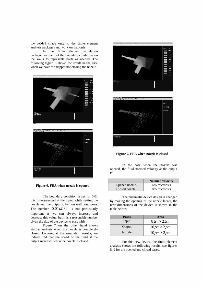
the oxide1 shape only to the finite element analysis packages and work on that only. In the finite element simulation package, we then set the boundary conditions on the walls to represents ports as needed. The following figure 6 shows the result in the case when we have the flapper not closing the nozzle. The boundary condition is set for 0.01 microliters/second at the input, while setting the nozzle and the output to be non wall conditions. The number sL /01.0 µ is not particularly
important as we can always increase and decrease this value, but it is a reasonable number given the size of the device to start with. Figure 7 on the other hand shows similar analysis when the nozzle is completely closed. Looking at the simulation results, we indeed find that the speed of the fluid at the output increases when the nozzle is closed.
In the case when the nozzle was opened, the fluid normed velocity at the output is:
Normed velocity Opened nozzle 6e5 microns/s Closed nozzle 8e5 microns/s
The pneumatic device design is changed by making the opening of the nozzle larger, the new dimensions of the device is shown in the table below:
Ports Area Input mm µµ 28 ×
Output mm µµ 210 ×
Nozzle mm µµ 210 ×
For this new device, the finite element analysis shows the following results, see figures 8, 9 for the opened and closed cases.
Figure 6. FEA when nozzle is opened
Figure 7. FEA when nozzle is closed

For this new design we get the following change in output velocity
Normed velocity Opened nozzle 4e5 microns/s Closed nozzle 8e5 microns/s
DISCUSSION To find out how much the pressure difference experienced by the cantilever beams, we use the Bernoulli equation which relates the change in velocity to the change in pressure:
( )21
222
1VVP −=∆ ρ
Since the air density is around 1.23 kg/m3, we have for the first case
N012-6.8880e*
0.1722Pa
=∆==∆
PAF
P
For the second case, we have
N011-1.1808e*
0.2952Pa
=∆==∆
PAF
P
Note that the cross sectional area takes into account the area of the dimple at the beam’s center. Obviously these are very small forces exerted on the cantilever beams, to increase these forces we need to go back and repeat the simulations for the case when the incoming flowing flow is larger than sL /01.0 µ .
To calculate the deflection of the beams we can use the following formula:
axxaEI
Fxy
axaxEI
aFy
≤−=
>−=
),3(6
),3(6
)(
2
2
Figure 8. FEA when nozzle is opened
Figure 9. FEA when nozzle is closed Figure 10.
This equation gives a deflection value of 2.1e-13m when the applied force is 1.18e-11 N. Since this is a small value of deflection that will usually go unnoticed, it is important to increase the flow at the input until getting a satisfactory pushing force.
CONCLUSIONS
The simulations shown is done on every part of the whole system independently. A sort of integrated simulation was not done in which we see all parts working together and influencing the performance of every other part in the whole system. This sort of problem limited the ability to find optimum values for the geometries of the different parts of the device when certain input out relation is desired. But in any case, with reasonable assumptions we were able to separate the different FEA analysis from each other to make things simpler.
The key value in this device is the input flow, because it is obvious that when we increase this value we will be able to get stronger forces applied to the cantilever beams.
SUMMARY
The main point and main conclusion of this paper is that we can have a pneumatic switch on the micro scale to turn the power of a fluid on and off, and to use this change in power to move and push things mechanically at the same time. The design obviously will be much more superior if the simulation was done without any assumption, and if it was possible to run the whole system as one part. Take for example what will happen to the thermal microactuator while closing the nozzle. What about the resistance it faces, is the force of the actuator enough to overcome such resistance. Another problem is how the heat of the actuator will affect the fluid flow inside the pneumatic device. These are all important points that where not considered in this research.
REFERENCES
[1] Araki K., Chen N., Ishino Y., "Characteristics of a Force-Balance Nozzle-Flapper Type Pneumatic Pressure Control
Proportional Valve ", Journal Japanese Hydraulic, Pneumatic Society, Vol 26, Issue 2, p. 184-90 March 1995.
[2] Esposito A., “Fluid Mechanics with Applications” , Prentice Hall 1998.
[3] E. Koelsar, S. KO, J. Howard, P. Allen, J. Wilken, N. Boydston, M. Ruff, R. Wilks, “ In- Plane tip deflection and force achieved with asymmetrical polysilicon electrothermal microactuators” , Thin Solid Films, p. 719-726, 2000.
[4] Ogata, K. “Modern Control Engineering” , Prentice Hall 1992
[5] Yamamoto T., Nakada T., Kagawa T., Tanaka K., "Study on Characteristics of Pneumatic Nozzle Flapper Valve Considering Unsteady Flow Force of Jet Through Nozzle", Proc. of ASME/JSME FEDSM’99, F-215, July, 1999