pneumatic direct-acting pressure reducing valve for steam ...the pn-dr pneumatic direct-acting...
TRANSCRIPT

172-65519MA-03 (PN-DR) 24 January 2018
Pneumatic Direct-acting Pressure Reducing Valve for Steam and Air
PN-DR
Copyright © 2018 by TLV CO., LTD.
All rights reserved

172-65519MA-03 (PN-DR) 24 Jan 2018
1
Contents
Contents ............................................................................ 1
Introduction ....................................................................... 1
Safety Considerations ....................................................... 2
Specifications .................................................................... 4
Acceptable Operating Range ............................................ 4
Correct Usage of the PN-DR Direct-acting Pressure
Reducing Valve ................................................................. 6
Configuration ..................................................................... 5
Installation ......................................................................... 8
Adjustment ...................................................................... 11
Maintenance .................................................................... 12
Disassembly .................................................................... 13
Reassembly .................................................................... 16
Troubleshooting .............................................................. 17
Product Warranty ............................................................ 20
Introduction
Thank you for purchasing the PN-DR pneumatic direct-acting pressure
reducing valve for steam and air.
This product has been thoroughly inspected before being shipped from the factory. When the product is delivered, before doing anything else, check the specifications and external appearance to make sure nothing is out of the ordinary. Also be sure to read this manual carefully before use and follow the instructions to be sure of using the product properly.
The PN-DR pneumatic direct-acting pressure reducing valve provides a
more stable secondary pressure than conventional direct-acting reducing valves. The PN-DR is designed for a long service life, and is made of
stainless steel for superior durability.
For products with special order specifications or options, if detailed instructions for the special order specifications or options are not contained in
this manual, please contact for full details.
This instruction manual is intended for use with the model(s) listed on the front cover. It is necessary not only for installation but for subsequent maintenance, disassembly/reassembly and troubleshooting. Please keep it in a safe place for future reference.

172-65519MA-03 (PN-DR) 24 Jan 2018
2
Safety Considerations Read this section carefully before use and be sure to follow the instructions.
Installation, inspection, maintenance, repairs, disassembly, adjustment and valve opening/closing should be carried out only by trained maintenance personnel.
The precautions listed in this manual are designed to ensure safety and prevent equipment damage and personal injury. For situations that may occur as a result of erroneous handling, three different types of cautionary items are used to indicate the degree of urgency and the scale of potential damage and danger: DANGER, WARNING and CAUTION.
The three types of cautionary items above are very important for safety: be sure to observe all of them as they relate to installation, use, maintenance,
and repair. Furthermore, TLV accepts no responsibility for any accidents or damage occurring as a result of failure to observe these precautions.
Symbols
Indicates a DANGER, WARNING or CAUTION item.
DANGER
Indicates an urgent situation which poses a threat of death or serious injury
WARNING
Indicates that there is a potential threat of death or serious injury
CAUTION
Indicates that there is a possibility of injury or equipment / product damage
CAUTION
Install properly and DO NOT use this product outside the
recommended operating pressure, temperature and other
specification ranges.
Improper use may result in such hazards as damage to the product
or malfunctions that may lead to serious accidents. Local
regulations may restrict the use of this product to below the
conditions quoted.
Take measures to prevent people from coming into direct
contact with product outlets.
Failure to do so may result in burns or other injury from the
discharge of fluids.
When disassembling or removing the product, wait until the
internal pressure equals atmospheric pressure and the
surface of the product has cooled to room temperature.
Disassembling or removing the product when it is hot or under
pressure may lead to discharge of fluids, causing burns, other
injuries or damage.
Be sure to use only the recommended components when
repairing the product, and NEVER attempt to modify the
product in any way.
Failure to observe these precautions may result in damage to the
product and burns or other injury due to malfunction or the
discharge of fluids.
Safety considerations continued on next page.

172-65519MA-03 (PN-DR) 24 Jan 2018
3
CAUTION
Do not use excessive force when connecting threaded pipes
to the product.
Over-tightening may cause breakage leading to fluid discharge,
which may cause burns or other injury.
Use only under conditions in which no freeze-up will occur.
Freezing may damage the product, leading to fluid discharge,
which may cause burns or other injury.
Use only under conditions in which no water hammer will
occur.
The impact of water hammer may damage the product, leading to
fluid discharge, which may cause burns or other injury.

172-65519MA-03 (PN-DR) 24 Jan 2018
4
Specifications
Install properly and DO NOT use this product outside the recommended
operating pressure, temperature and other specification ranges.
Improper use may result in such hazards as damage to the product or
malfunctions which may lead to serious accidents. Local regulations
may restrict the use of this product to below the conditions quoted.
CAUTION
Use only under conditions in which no freeze-up will occur. Freezing
may damage the product, leading to fluid discharge, which may cause
burns or other injury. CAUTION
Refer to the product nameplate for detailed specifications.
Model
Nominal Diameter
Maximum Operating Temperature
Valve No.*
Secondary Pressure Adjustable Range
Primary PressureRange
Production Lot No.
* Valve No. is displayed for products with options. This item is omitted from the nameplate when there are no options.
Acceptable Operating Range Model PN-DR-2 PN-DR-6
Primary Pressure Range 0.2 - 1.6 MPaG (30 – 230 psig)
Adjustable Pressure Range
0.014 – 0.2 MPaG (2 – 30 psig)
(but limited to 1/30 of
primary pressure)
0.18 - 0.6 MPaG (27 – 85 psig)
Secondary pressure must not exceed 90% of primary pressure
Maximum Operating Temperature 220 °C (428 °F)
Motive Air Pressure 0 - 1.0 MPaG (0 – 150 psig) (Oil free air, filtered to 5 µm)
(1 MPa = 10.197 kg/cm2)

172-65519MA-03 (PN-DR) 24 Jan 2018
5
Configuration
No. Name A*
1 B*
1 C*
1 D*
1 E*
1
1 Body
2 Cover
3 Screen
4 Coil Spring
5 Main Valve
6 Valve Seat Gasket
7 Valve Seat
8 Spacer*3
9 Snap Ring
10 Valve Stem
11 Bellows
12 Cover Gasket*2
13 Coil Spring
14 Spring Guide
15 Steel Ball
16 Cover Bolt
17 Holder Nut
18 Adjustment Handle
19 Nameplate
20 Retaining Ring
21 Retainer
22 Seal Ring
23 Packing
24 Slide Bearing*2 *
3
25 Snap Ring*2 *
3
*1Replacement parts are available
only in the following kits:
A: Maintenance Kit
B: Repair Kit for Spacer
C: Repair Kit for Main Valve,
D: Repair Kit for Bellows
E: Repair Kit for Adjustment Handle
*2Number of parts: 2 pieces
*3Shipped as a unit

172-65519MA-03 (PN-DR) 24 Jan 2018
6
Correct Usage of the PN-DR Direct-acting Pressure
Reducing Valve
Install properly and DO NOT use this product outside the recommended
operating pressure, temperature and other specification ranges.
Improper use may result in such hazards as damage to the product or
malfunctions which may lead to serious accidents. Local regulations
may restrict the use of this product to below the conditions quoted.
CAUTION
1. The PN-DR should be operated only within its specifications.
2. Installing an ON/OFF Valve (Solenoid Valve or Motorized Valve)
MotorizedValve
Inlet Side
PN-DR
Outlet Side
SolenoidValve
PN-DR
If an on-off valve is required to stop supply of steam or air to the equipment,
install it at the inlet side of the PN-DR.
If a solenoid valve is installed at the outlet of the PN-DR, it will cause heavy
chattering and may lead to damage of the PN-DR. (When the on-off valve opens,
the secondary pressure of the reducing valve changes from zero to the set
pressure. Passing through an area of the reducing ratio of less than 30:1 where
adjustment is impossible, chattering occurs momentarily.) To save energy, install
the on-off valve as near to the boiler, or compressor, as possible.
NOTE: To prevent water hammer, it is recommended that a slow-acting motorized on-off valve be used. If a fast-acting solenoid valve is used, the potential water hammer effect can damage the equipment and the pressure reducing valve.
3. Installing a Control and/or Safety Valve
SafetyValve
Steam- or Air-usingEquipment
ControlValvePN-DR
SafetyValve
ControlValve
Steam- or Air-usingEquipment
PN-DR
A control valve (i.e. for temperature control) installed between the PN-DR and the
equipment (downstream of the PN-DR) may raise the pressure between the
PN-DR and the control valve when the control valve is closed, depending on their
proximity. Therefore, this valve should be installed close to the steam- or air-using
equipment, as illustrated. Also, a safety valve should be installed downstream of
the control valve.
NOTE: When installing a safety valve to protect the steam- or air-using equipment, be sure to install it on the steam- or air-using equipment, or directly before the inlet of the equipment. If the safety valve is installed between the PN-DR
and a control valve, an eventual pressure rise could activate the safety valve.

172-65519MA-03 (PN-DR) 24 Jan 2018
7
4. Recommended Straight Pipe Runs
In order to ensure a stable flow of air or steam, the piping upstream and
downstream of the PN-DR must be straight runs. If the PN-DR is installed either
directly before or after an elbow or control valve, unevenness in flow may result in
chattering and unstable pressure.
To ensure a stable flow, it is recommended that the PN-DR be installed on
straight runs of piping, as illustrated below.
Inlet (primary side) of the PN-DR NOTE: d = pipe diameter
Maintain a straight piping run
of 10 d or more when a
manual valve, a strainer or an
elbow, etc. is installed.
(Example: if nominal size is 25
mm (1 in), have 250 mm (10 in)
or more)
PN-DR
10 d or more
Valve, strainer,
elbow, etc.
PN-DR
Less than10 d
Valve, strainer,
elbow, etc.
Maintain a straight piping run
of 30 d or more when an
automated valve (on-off valve)
is installed.
(Example: if nominal size is 25
mm (1 in), have 750 mm (30 in)
or more)
AutomatedValve
PN-DR
30 d or more
AutomatedValve
PN-DR
Less than30 d
Outlet (secondary side) of the PN-DR
Maintain a straight piping run
of 15 d or more when a manual valve, a strainer or an elbow, etc. is installed. (Example: if nominal size is 25 mm (1 in), have 375 mm (15 in) or more)
PN-DR
Valve, strainer,
elbow, etc.
15 d or more
PN-DRValve,
strainer, elbow, etc.
Less than15 d
Maintain a straight piping run
of 30 d or more when a safety valve is installed. (Example: if nominal size is 25 mm (1 in), have 750 mm (30 in) or more)
PN-DR
Safety Valve
30 d or more
Less than30 d
PN-DR
Safety Valve
–
Maintain a straight piping run of
30 d or more when another
pressure reducing valve is
installed. (Two-stage pressure
reduction)
(Example: if nominal size is 25
mm (1 in) , have 750 mm (30
in) or more)
PressureReducing
Valve PN-DR
30 d or more
PressureReducing
Valve PN-DR
Less than30 d
172-65519MA-03 (PN-DR) 24 Jan 2018
8
Installation
Install properly and DO NOT use this product outside the recommended
operating pressure, temperature and other specification ranges.
Improper use may result in such hazards as damage to the product or
malfunctions which may lead to serious accidents. Local regulations
may restrict the use of this product to below the conditions quoted.
CAUTION
Take measures to prevent people from coming into direct contact with
product outlets. Failure to do so may result in burns or other injury from
the discharge of fluids. CAUTION
Installation, inspection, maintenance, repairs, disassembly, adjustment and valve
opening/closing should be carried out only by trained maintenance personnel.
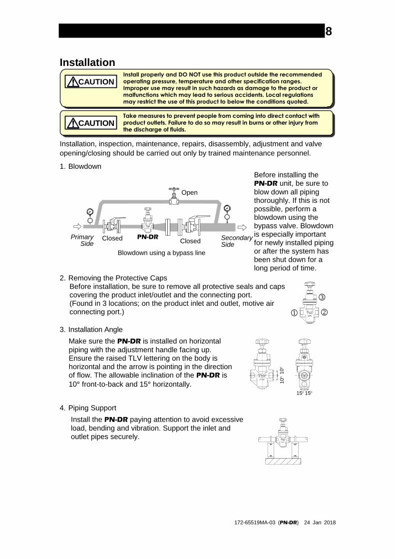
1. Blowdown
Open
Closed ClosedPN-DRPrimary
SideSecondarySide
Blowdown using a bypass line
Before installing the PN-DR unit, be sure to
blow down all piping thoroughly. If this is not possible, perform a blowdown using the bypass valve. Blowdown is especially important for newly installed piping or after the system has been shut down for a long period of time.
2. Removing the Protective Caps Before installation, be sure to remove all protective seals and caps covering the product inlet/outlet and the connecting port. (Found in 3 locations; on the product inlet and outlet, motive air connecting port.)
3. Installation Angle
4. Piping Support
Install the PN-DR paying attention to avoid excessive
load, bending and vibration. Support the inlet and outlet pipes securely.
Make sure the PN-DR is installed on horizontal
piping with the adjustment handle facing up. Ensure the raised TLV lettering on the body is horizontal and the arrow is pointing in the direction of flow. The allowable inclination of the PN-DR is
10° front-to-back and 15° horizontally.
10
10
1515

172-65519MA-03 (PN-DR) 24 Jan 2018
9
5. Maintenance Space Leave sufficient space for maintenance, inspection and repair.
Unit: mm (in)
200
(8)
200
(8)
200 (8) 200 (8)
6. Piping Size/Diffuser
If it is expected that the secondary flow velocity will be more than 30m/s (100 ft/s), install a diffuser in order to keep the flow velocity below 30m/s(100 ft/s). If the distance between the PN-DR and the steam-
and air-using equipment is great, a possible drop in pressure should be taken into consideration when selecting the piping size. If installing a strainer,
horizontal installation is
recommended in order to
prevent pooling of
condensate.
Straight piping: 10 d or longer upstream, 15 d or longer downstream
Diffuser
PN-DRPrimarySide
SecondarySide
PN-DRPrimarySide
SecondarySide
7. Two-stage Pressure Reduction
PressureGauge
Bypass Valve
InletValve
OutletValve
Safety Valve(Relief Valve)
PrimarySide
PressureReducing
Valve
Bypass Valve
SecondarySide
InletValve
OutletValve
PN-DR
PressureGauge
PressureGauge
InletValve
OutletValve
Safety Valve(Relief Valve)
PrimarySide
PN-DR
Bypass Valve
SecondarySide
PressureGauge
Employ 2-stage pressure reduction if the required reduction is not possible due to PN-DR operating range
limitations (when it is not possible to reduce to the desired pressure using a single PN-DR).

172-65519MA-03 (PN-DR) 24 Jan 2018
10
8. Accessories
BallValve
PN-DR BallValve
Globe Valve
PrimarySide
SecondarySide
PN-DRPrimarySide
SecondarySide
Always install a bypass line. At the inlet and outlet, install a pressure gauge and a shut-off valve. Ball valves, which will not retain condensate, are recommended for inlet/outlet shut-off valves. The nominal pipe size for the bypass line should be
1/2 or
greater of the primary pipe size.
9. Motive Air
Motive AirConnection Port
Air Regulator for Motive Air
Supply oil free air filtered to 5 µm for the motive air and adjust the air pressure to match desired value by using an air regulator or similar device.

172-65519MA-03 (PN-DR) 24 Jan 2018
11
Adjustment The PN-DR can set secondary pressure(s) either by operation of the adjustment
handle or adjustment of the motive air pressure, or a combination of both.
To avoid problems such as water hammer and to protect steam- and air-using
equipment, the PN-DR should be correctly adjusted.
1. It is necessary to blow down all pipelines thoroughly. The blowdown is especially
important if the line is new or has been shut down for a long period of time. Take
particular care to ensure that matter such as condensate and dirt does not remain
inside the steam- and air-using equipment. (Stay clear of any pressurized blow-out
from the safety valve.)
2. Make sure that the shut-off and bypass valves
located upstream and downstream of the PN-DR are completely closed.
Counter-clockwise
Fully raise the
adjustment handle
3. Turn the adjustment handle counter-clockwise
to free the coil spring.
4. Slowly, fully open the shut-off valve at the inlet of the PN-DR.
5. Slightly open the shut-off valve at the outlet of the PN-DR.
6. Slowly turn the adjustment handle clockwise until the desired secondary (steam or
air) pressure is obtained with the pressure of the coil spring. Wait several minutes.
Be careful not to make rapid adjustments as the safety valve may be activated or
equipment may be damaged by water hammer.
Clockwise
Increase Pressure
Counter-clockwise
Decrease Pressure 7. Slowly, fully open the shut-off valve at the outlet of the PN-DR.
8. When shutting down the system, always close the outlet shut-off valve first and
then the inlet valve.

172-65519MA-03 (PN-DR) 24 Jan 2018
12
Maintenance
Take measures to prevent people from coming into direct contact with
product outlets. Failure to do so may result in burns or other injury from
the discharge of fluids. CAUTION
Be sure to use only the recommended components when repairing the
product, and NEVER attempt to modify the product in any way. Failure to
observe these precautions may result in damage to the product or burns
or other injury due to malfunction or the discharge of fluids.
CAUTION
Operational Check
To ensure a long service life for the PN-DR, the following inspection and
maintenance should be performed regularly.
Part Inspection and Maintenance Frequency
Screen Disassemble and clean annually. If there is substantial blockage, install a strainer (approximately 60 mesh) ahead of the PN-DR.
Main Valve, Valve Seat If there is chattering or dirt, premature wear may result.
Valve Stem, Spacer (Slide Bearing)
If hunting or chattering takes place, premature wear may result.
Bellows If hunting or chattering takes place, cracks or fatigue may develop in a short period of time.
Seal Ring Replace annually. Premature wear may occur.
Packing Replace annually. Premature wear may occur.

172-65519MA-03 (PN-DR) 24 Jan 2018
13
Disassembly
When disassembling or removing the product, wait until the internal
pressure equals atmospheric pressure and the surface of the product
has cooled to room temperature. Disassembling or removing the
product when it is hot or under pressure may lead to discharge of fluids,
causing burns, other injuries or damage.
CAUTION
It is a recommended practice to dismantle and inspect the PN-DR once a year for
preventive maintenance purposes. It is especially important to perform an inspection immediately after the initial run of a new line or before or after equipment such as a heater is taken out of service for a long period of time. (Installation, inspection, maintenance, repairs, disassembly, adjustment and valve opening/closing should be carried out only by trained maintenance personnel.)
Remove all steam/pressurized air from the piping (both upstream and downstream). Remove all motive air pressure. Wait for the body to cool before attempting to remove the PN-DR from the line. Then
remove the PN-DR from the piping, and secure it in a vise to perform the inspection.
Disassembling the Adjusting Section
Loosen the adjustment handle completely and remove the cover bolts. After
removing the cover, you will see the steel ball, the spring retainer and the coil spring.
Check for seizure or any damaged screw threads.
Remove the retaining ring. The seal ring and the packing can be removed by
loosening the adjustment handle and the holder nut.
Check and make sure that the seal ring has not deteriorated and the packing has
no abnormalities.
Retaining Ring
Steel Ball
Spring Guide
Coil Spring
Cover Bolt
Cover
Retainer
Cover Gasket
Packing
Seal Ring
Holder Nut
Adjustable Handle

172-65519MA-03 (PN-DR) 24 Jan 2018
14
Disassembling the Bellows Section Remove the bellows from the body, then the valve stem. Pinch the straight sections of the snap ring that is holding the spacer together using a tool such as needle-nose pliers and remove the snap ring. Remove the spacer.
Valve Stem
Snap Ring*1
Slide Bearing*1
Spacer
Slide Bearing*1
Snap Ring*1
Body
Bellows
Cover Gasket
Snap Ring*2
*1Cannot be removed individually as it is incorporated with the spacer
*2Insert the snap ring so that both ends are facing down.
Disassembling the Valve Section Loosen the valve seat with a wrench and remove it from the body. The coil spring is exerting an upward pressure on the bottom of the valve seat, so be careful that the valve seat is not thrown out. After removing the valve seat, remove the main valve, the coil spring and the screen.
Body
Screen
Coil Spring
Valve Seat
Valve Seat Gasket
Main Valve
Cleaning After inspection and removal of any abnormalities, clean and reassemble the parts. The following parts will require cleaning before reassembly:
Threads of the adjustment handle, threads of the cover, bellows, holder nut, valve stem, main valve, valve seat, spacer (including slide bearing), screen
It is permissible to clean using water. However, cleaning with a mild detergent is recommended for more effective cleaning.
172-65519MA-03 (PN-DR) 24 Jan 2018
15
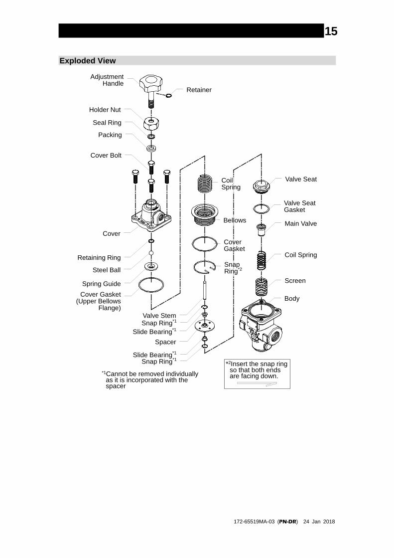
Exploded View
Valve Seat
Valve SeatGasket
Main Valve
Coil Spring
Screen
Body
AdjustmentHandle
Packing
Cover Bolt
Cover
Retaining Ring
Steel Ball
Spring Guide
Spacer
Slide Bearing*1
Slide Bearing*1
Snap Ring*1
Snap Ring*1
Bellows
CoverGasket
SnapRing*2
Valve Stem
CoilSpring
Holder Nut
Seal Ring
Retainer
Cover Gasket(Upper Bellows
Flange)
*1Cannot be removed individually as it is incorporated with the spacer
*2Insert the snap ring so that both ends are facing down.
172-65519MA-03 (PN-DR) 24 Jan 2018
16
Reassembly
Reassemble the unit using the same procedure as used for disassembling it; but in
reverse order. In addition, observe the following precautions:
1. The PTFE gasket may be re-used if free from fault, crushing or deformation.
2. Apply anti-seize to the steel ball and threaded portions of screws, bolts and the
adjustment handle. Apply a small amount of anti-seize agent to the threads of
the valve seat carefully to ensure it does not come into contact with other parts.
3. Fasten the bolts one at a time in a diagonal pattern alternately to provide
uniform seating.
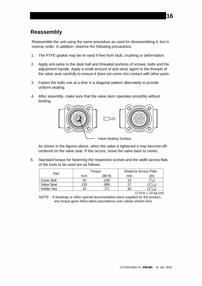
4. After assembly, make sure that the valve stem operates smoothly without
binding.
As shown in the figures above, when the valve is tightened it may become off-
centered on the valve seat. If this occurs, move the valve back to center.
5. Standard torque for fastening the respective screws and the width across flats
of the tools to be used are as follows:
Part Torque Distance Across Flats
Nm (lbf·ft) mm (in)
Cover Bolt 25 (19) 13 (1/2)
Valve Seat 120 (88) 27 (11/16)
Holder Nut 10 (7) 30 (13/16)
(1 Nm 10 kgcm)
NOTE: - If drawings or other special documentation were supplied for the product,
any torque given there takes precedence over values shown here.
Valve Seating Surface

172-65519MA-03 (PN-DR) 24 Jan 2018
17
Troubleshooting
When disassembling or removing the product, wait until the internal
pressure equals atmospheric pressure and the surface of the product
has cooled to room temperature. Disassembling or removing the
product when it is hot or under pressure may lead to discharge of fluids,
causing burns, other injuries or damage.
CAUTION
This product is shipped after stringent checks and inspection, and should perform its
intended function for a long period of time without failure. However, should there be
any problem encountered in the operation of the PN-DR, consult the troubleshooting
guide below. Problems are classified as follows:
1. The secondary pressure does not increase
2. The secondary pressure cannot be adjusted or increases abnormally
3. Hunting (fluctuation of the secondary pressure) occurs
4. Chattering (a heavy mechanical noise) occurs
5. Abnormal noises
Major causes for the above problems are usage under non-specified conditions (out
of specification), insufficient pressure or flow rate, and clogs by dirt and scale.
To ensure performance for a long period of time, it is recommended that the
“Acceptable Operating Range”, “Correct Usage of the PN-DR Direct-acting Pressure
Reducing Valve” and “Adjustment” sections be reviewed.
Problem Symptom Cause Remedy
The secondary pressure does not rise
Pressure does not increase
No steam/air is being supplied
Check the primary/secondary piping and valves of the unit The valve at the primary
side is closed
No motive air is being supplied
Check motive air supply
The entrance to the screen or strainer is clogged
Clean or blow down
Flow rate exceeds specifications
Check the flow rate; check the model selection, replace with a more suitable unit if necessary
It exceeds the adjustable pressure range
Check the model selection, replace with a more suitable unit if necessary
The secondary pressure cannot be adjusted or increases abnormally
Adjustment is difficult and set pressure varies
The flow rate is too low Check the flow rate; check the model selection, replace with a unit that has a smaller nominal diameter or more a suitable unit if necessary
Pressure fluctuation at the primary side is large
Check the primary pressure; check the model selection, replace with a more suitable unit if necessary
Buildup on the valve stem prevents smooth movement through the spacer
Clean and inspect the valve stem and spacer
Troubleshooting continued on next page

172-65519MA-03 (PN-DR) 24 Jan 2018
18
Problem Symptom Cause Remedy
The
secondary
pressure
cannot be
adjusted or
increases
abnormally
Adjustment is difficult and set pressure varies
Flow rate fluctuation is too large
Check the flow rate, re-set the pressure; check the model selection, replace with a more suitable unit if necessary
The motive air pressure fluctuates
Check motive air pressure
Adjustment is
difficult and set
pressure varies
The adjustment handle has
seized
Replace with a new
adjustment handle
The holes in the spacer are
clogged
Clean
The slide bearing is
distorted or damaged
Replace with a new spacer
(when replacing the slide
bearing or snap ring, these
parts need to be replaced
as a set with the spacer)
The bellows is distorted or
damaged
Replace with a new bellows
The selected model is
inappropriate for the service
conditions (specifications)
Check the model selection,
replace with a more suitable
unit if necessary
Upon closing the
valves at the
secondary side,
the secondary
pressure abruptly
rises as high as
the primary
pressure
The bypass valve is leaking Check, clean, and replace
with a new valve if
necessary
There is a build-up of dirt on
or damage to the main
valve or the valve seat
Clean and align
Hunting or
chattering
occurs
Occurs at low
steam/air
demand
The flow rate is too low Check the flow rate; check
the model selection, replace
with a unit that has a
smaller nominal diameter or
a more suitable unit if
necessary
Hunting never
stops
There is too high a
reduction ratio
Use two-stage reduction
The selected model is
inappropriate for the service
conditions (specifications)
Check the model selection,
replace with a more suitable
unit if necessary
Chattering never
stops
Condensate is entrained Install a steam trap; check
the piping
The selected model is
inappropriate for the service
conditions (specifications)
Check the model selection,
replace with a more suitable
unit if necessary
Troubleshooting continued on next page

172-65519MA-03 (PN-DR) 24 Jan 2018
19
Problem Symptom Cause Remedy
Abnormal
noises
Makes a high-
pitched noise
The required pressure
reduction exceeds
specifications
Use two-stage reduction
Flow rate exceeds
specifications
Check the flow rate; check
the model selection, replace
with a unit that has larger
nominal diameter or a more
suitable unit if necessary
A valve installed close to the
reducing valve opens/closes
too quickly
Install the valve at as great
a distance away as possible
NOTE: When replacing parts with new, use the parts list for reference and replace with parts
from the Maintenance Kit, Repair Kit, etc. (Please note that replacement parts are only
available in pre-packaged kits.)

172-65519MA-03 (PN-DR) 24 Jan 2018
20
Product Warranty 1. Warranty Period
One year following product delivery. 2. Warranty Coverage
TLV CO., LTD. warrants this product to the original purchaser to be free from defective materials and workmanship. Under this warranty, the product will be repaired or replaced at our option, without charge for parts or labor.
3. This product warranty will not apply to cosmetic defects, nor to any
product whose exterior has been damaged or defaced; nor does it apply in the following cases:
1) Malfunctions due to improper installation, use, handling, etc., by other
than TLV CO., LTD. authorized service representatives.
2) Malfunctions due to dirt, scale, rust, etc. 3) Malfunctions due to improper disassembly and reassembly, or
inadequate inspection and maintenance by other than TLV CO., LTD. authorized service representatives.
4) Malfunctions due to disasters or forces of nature.
5) Accidents or malfunctions due to any other cause beyond the control of TLV CO., LTD.
4. Under no circumstances will TLV CO., LTD. be liable for consequential economic loss damage or consequential damage to property.
* * * * * * *
For Service or Technical Assistance:
Contact your representative or your regional office.
Manufacturer
881 Nagasuna, Noguchi Kakogawa, Hyogo 675-8511, JAPAN Tel: 81-(0)79 - 427 - 1800