pneumatic connectors handbook - cairo...
TRANSCRIPT

PneumaticConnectorshandbook
Catalogue 0093-UKJanuary 2002

Selection guide
* Chemical nickel plated only. ** Prestoweld 2 tubing only
(1) Available with threaded ends only. Depends on fitting type used to connect to the tube.
For your safety!Under certain circumstances, tube fittings can be subjected to extreme loadings such as vibration and uncontrolled pressure peaks.Only by using genuine Parker components and following the Parker assembly instructions can you be assured of the reliability and safety of theproducts and their conformity to the applicable standards.Failure to follow this rule can adversely affect the functional safety and reliability of products, cause personal injury, property damage, and resultin loss of your guarantee rights.In any case, guarantee is limited only to the Parker products.
(2) Welding sparks.
Application
Pne
umat
ic a
utom
atio
n
Agg
ress
ive
envi
ronm
ents
Pri
mar
y va
cuum
- 0
bar
0 - 1
0 ba
r10
- 16
bar
16 -
18 b
ar18
- 25
bar
25 -
40 b
ar40
- 60
bar
60 -
100
bar
Poly
uret
hane
tube
PE
BA
tube
Poly
ethy
lene
tube
Poly
amid
e 11
/12
tube
Cop
per
tube
Ste
el
Sta
inle
ss S
teel
Syn
thet
ic r
ubbe
rPo
lyur
etha
ne
Indu
stri
al fl
uids
Pneu
mat
ic c
oppe
r tub
e in
stal
latio
ns
Pne
umat
ic p
ower
Tube Ermeto HoseWorking pressure
Prestolok2
PrestolokMicro
Prestolok
Metrulok
PL
Ermeto
Brassadaptors
Pneumaticadaptors
Ballvalves
Quickcouplings
Hose andfittings
Brass adapt.for automotive
industry
Ther. Sing.tub. and
Pn.-TU.Bu.
Prestoweld2
Pneu. int.funct. ftgs.
*
**(2)
(1) (1) (1) (1)
(1) (1) (1) (1)
(1) (1) (1) (1)
(1) (1) (1) (1)
(1) (1) (1) (1)
(1)
(1)
(1) (1)
*
Fo
r m
ore
de
taile
d in
form
atio
n,
ple
ase
co
nsu
lt th
e s
ect
ion
co
rre
spo
nd
ing
to
th
e s
ele
cte
d p
rod
uct
fro
m t
his
ca
talo
gu
e.
FluidConnectors

J
D
F
H
FluidConnectors
General index (an index by part number is also available at the end of this catalogue)
Parker’s missionTo be an outstanding manufacturer who, through continuous productivity andquality improvements, makes effective, profitable use of its ressources to producecustomer-satisfying products and services.
Designmanual
Technical data, pneumatic system calculations,installation guide.
Prestolok 2
Prestolok Micro
Prestolok
Prestoweld 2
Pneumatic integratedfunction fittings
Metrulok
PL
Ermeto
Brass adaptors
Pneumatic adaptors
Ball valves
Quickcouplings
Push-Lokhose and fittings
Thermoplasticsingle tubes andPneumo-Tube bundles
Accessories
Push-in fitting with thermoplastic bodyand protective cap for pneumatic applications.
Mini push-in fitting with thermoplastic bodyfor miniature pneumatic applications.
Brass push-in fitting for fluid and arduouspneumatic applications.
A complete range from flow control to endof stroke pressure sensors.
Ready for use brass bite type fitting for usewith copper or plastic tubing.
A two piece fitting specifically designedfor plastic tubing.
Bite type fitting for use with metal or plastic tubing.
A wide range of configurations and thread terminations.
Brass ball valves for many fluid handling applications.
Low-pressure ; self-grip hose without clamps.
Brass and steel quick couplings, as well as blow gunsfor all pneumatic applications.
Polyamide, Polyethylene, Polyurethane tubing for allpneumatic applications.
Accessories for pneumatic installations.
Spark resistant push-in fittings.
A wide range of adaptors for pneumatic applications.
A
B
C
E
I
G
L
M
N
O
P
Q
KBrass adaptorsfor automotiveindustry
A wide range of adaptors for air and water coolingcircuits for welding applications.


Pneumaticconnectorsdesign manual

Pneumatic connectors design manual
Catalogue 0093-UKFluidConnectors

Pneumatic connectors design manual
A 1 Catalogue 0093-UKFluidConnectors
AIndex Pages
The Parker pneumatic connection system A 2 - A 3
Thread configurations BSPP and BSPT pipe threads A 4ISO metric pipe threads A 5UNF threads A 6NPT threads A 7
The sealing of threaded connections Parallel threads A 8Taper threads A 9
Threaded connections and corrosion Atmospheric corrosion A 10Compatibility of different base metals A 11
Hose and tubing used in pneumatics Polyamide tubing / PEBA tubing A 12Polyurethane tubing A 13Hoses A 13 to A 15Copper and steel tube A 15
Pneumatic system calculations Power losses A 16Calculation of flow rate A 17Orifice diameter for different cylinders A 18Cylinder response time A 19Air admission time A 19Maximum recommended flow A 20Pressure drop through shaped A 20componentsAir consumption A 20 - A 21Leakage A 21
Installation guidelines A 22 to A 25
Pneumatic control Cylinders, integrated fittings (flow A 26 - A 27control valves, check valves,exhaust valves, silencers)
Connectors for pneumatic systems Brass push-in fittings A 28Brass and steel connectors A 29
Terms used in pneumatics A 30 - A 31
Pneumatic symbols A 32 to A 34
Pneumatic Quick Coupling profiles A 35

The Parker pneum The Parker pneumatic connectionsystemFor more than 60 years, Parker hasdeveloped and manufactured themost complete range of componentsto serve hydraulic and pneumaticmarkets.
The specific range of pneumaticconnectors is designed and manu-factured in accordance with interna-tional standards to meet marketrequirements.
The objective of this manual is to aidthe design engineer in the selectionof pneumatic connectors for specificor general applications, dependantupon the individual constraints of thesystem.
The information enclosed should beconsidered as a basic guideline only.For further detailed information withregard to pneumatic systems, pleasecontact your Parker sales engineer.
Blow Guns :with or withoutsafety valving
PneumaticQuickcouplings :flow from 550l/min
Push-Lok Hose and fittings :low pressure, self grip hoseAssembly without clampsor special tools
Metrulok : one piece ready to usebite type fitting for use with eithercopper or plastic tubing
copper tube
plastic tube
copper tube
EO Ermeto Original:Bite type tube fitting systemwith metal or soft sealingfor use with either metal,copper or polyamide tubing
plastic tube

atic fitting system
Ball Valves :a wide range for manypneumatic applications
Thermoplasticsingle tubesand Pneumo
Tube bundles
Prestolok :Push-in fitting for polyamide,polyurethane and copper tubing
Prestoweld 2 :Spark resistant push-in fittings
Prestolok 2 :Push-in fitting with protective cap forpolyamide and polyurethane tubing.
Prestolok Micro :Miniature push in fitting for polyamideand polyurethane tubing.
PL : two piece fitting for all types ofplastic tubing.

Pneumatic connectors design manual
A 4 Catalogue 0093-UKFluidConnectors
A
BSPP BSPT Threads d1 l2 d4 a1 l1 b1 b2per nominal min. max. max. min. min.inch
Rs 1/8 R 1/8 28 9.73 3.97 15 1 8 8 5.5
Rs 1/4 R 1/4 19 13.16 6.05 19 1.5 12 12 8.5
Rs 3/8 R 3/8 19 16.66 6.35 23 2 12 12 8.5
Rs 1/2 R 1/2 14 20.95 8.16 27 2.5 14 14 10.5
Rs 3/4 R 3/4 14 26.44 9.2 33 2.5 16 16 13.0
Rs 1 R 1 11 33.25 10.39 40 2.5 18 18 -
Rs 1.1/4 R 1.1/4 11 41.91 12.7 50 2.5 20 20 -
Rs 1.1/2 R 1.1/2 11 47.80 12.7 56 2.5 22 22 -
Thread configurations
BSP threadsBSPP and BSPT pipe threadsBSPP and BSPT threads have athread angle of 55° and are themost widely used fastening threadsin pneumatic applications.The spot face surface must besquare to the pitch diameter andfree from longitudinal and spiral toolmarks.BSPP - British Standard PipeParallel threads for tubes andfittings where pressure-tight jointsare not made on the thread, i.e., aperipheral seal is used.BSPT - British Standard Pipe Taperthreads for tubes and fittings wherepressure-tight joints are made onthe threads.It is accepted practice to fit a BSPTBS 21 male thread into a BSPPfemale DIN 3852 port tapping forpneumatic applications. In certainexceptional cases the port may alsobe tapered.
Thread standardsBSPP thread to :ISO 228-1BS2779DIN 3852-2 - Form A,B,ENF E 03-005
BSPT thread to :ISO 7BS 21DIN 3852-2 - Form CNF E 03-004
Screwed studs and tapped holes toDIN 3852, form X, Z
NoteThe letters “Rs” are the accepted designation for a BSPP thread and the letter “R”represents a BSPT thread.
BSPT6.25° cone angle.Pressure-tightjoints on the thread
BSPP
min. forBSPT
BSPPPeripheral sealing(copper,aluminium,bonded, etc.)

Pneumatic connectors design manual
A 5 Catalogue 0093-UKFluidConnectors
A
d1 l1 f g d3 d5 α° b2 a2 Seal
M3x0.5** 3.25 - - 6.5 6.5 - 4.0 1.0 -
M5x0.8** 8.0 1.5 3.80 14 6.35 12 8.0 1.0 3.6x1.5
M8x1 10.0 1.5 6.55 17 9.10 12 10.0 1.0 6.2x1.5
M10x1 10.0 1.5 8.55 20 11.1 12 10.0 1.0 8.2x1.5
M12x1.5 11.5 2.3 9.85 22 13.8 15 11.5 1.5 9.4x2.1
M14x1.5 11.5 2.3 11.85 25 15.8 15 11.5 1.5 11.4x2.1
M16x1.5 13.0 2.3 13.85 27 17.8 15 13.0 1.5 13.4x2.1
M18x1.5 14.5 2.3 15.85 29 19.8 15 14.5 2.0 15.4x2.1
M20x1.5** 14.0 2.3 17.85 32 21.8 15 14.0 2.0 17.4x2.1
M22x1.5 15.5 2.3 19.85 34 23.8 15 15.5 2.0 19.4x2.1
Thread configurations
ISO metric pipe threadsISO metric pipe threadsISO metric pipe threads have athread angle of 60°.They have mostly been used in mi-niature pneumatic applicationsbecause of the availability of smallthread diameters, especially M5and M3*.They are also used extensively inthe automotive industry.There are two forms of sealing onmetric threads.
1. O-Ring sealing into a profiledport in accordance with ISO 6149
2. Peripheral sealing eg copper orbonded washer in accordance withISO 261 and 262
Thread standardsO-Ring sealing :ISO 6149DIN 3852 - Form F
Peripheral sealing :ISO R261 and R262DIN 3852-1 - Form GNF E03-013
Seals :DIN 7603NF E21 - 351
Ports :DIN 3852 - Part 3
* M3, M5 and M20 threads are not includedin the ISO specification
** Not ISO 6149
ISO 6149O-Ring sealing
ISO 261Peripheral sealing(copper, aluminium,bonded, etc.)

Pneumatic connectors design manual
A 6 Catalogue 0093-UKFluidConnectors
A
UNF threadsUNF threadsThe Unified thread has a threadangle of 60°, and is normally used inhydraulic applications. It also referredto as the "ISO inch size thread".UNF - Unified Fine threads for con-nections where pressure-tight jointsare not made on the threads, i.e., aperipheral seal is used.Reference example : 3/8-24-UNF2B3/8 = diameter24 = number of threads per inchA = external threadsB = internal threads1 = low precision2 = general purpose3 = high precisionThread standardsSAEJ514 (male threads)SAEJ1926 (female port)
Thread configurations
Thread size SAE d1 d3 d5 b1 a1 f g l1 α° O-ringand module min. min. ID Sectionthreads per inch
5/16-24 UNF -2mm 7.94 17 9.1 10 1.6 1.6 6.35 7.54
126.07 1.63
inch .310 .672 .358 .390 .062 .063 .250 .297 .239 .064
3/8-24 UNF -3mm 9.53 19 10.7 10 1.6 1.6 7.95 7.54
127.65 1.63
inch .380 .750 .421 .390 .062 .063 .313 .297 .301 .064
7/16-20 UNF -4mm 11.11 21 12.4 11 1.6 1.9 9.25 9.14
128.92 1.83
inch .440 .828 .487 .450 .062 .075 .364 .360 .351 .072
1/2-20 UNF -5mm 12.7 23 14 11 1.6 1.9 10.85 9.14
1210.52 1.83
inch .500 .906 .550 .450 .062 .075 .427 .360 .414 .072
9/16-18 UNF -6mm 14.28 23 15.6 13 1.6 2.1 12.24 9.93
1211.89 1.98
inch .560 .969 .616 .500 .062 .083 .482 .391 .468 .078
3/4-16 UNF -8mm 11.05 30 20.6 14 2.4 2.4 16.76 11.13
1516.36 2.21
inch .750 1.188 .811 .560 .940 .094 .660 .438 .644 .087
7/8-14 UNF -10mm 22.22 34 23.9 17 2.4 2.7 19.63 12.7
1519.18 2.46
inch .870 1.344 .942 .660 .940 .107 .773 .500 .755 .097
1.1/16-12 UN -12mm 26.99 41 29.2 19 2.4 3.2 27.18 15.09
1523.47 2.95
inch 1.060 1.625 1.148 .750 .940 .125 .945 .594 .924 .116
1.3/16-12 UN -14mm 30.15 45 32.3 19 2.4 3.2 27.18 15.09
1526.59 2.95
inch 1.190 1.765 1.273 .750 .940 .125 1.070 .594 1.047 .116
1.5/16-12 UN -16mm 33.34 49 35.5 19 3.2 3.2 30.35 15.09
1529.74 2.95
inch 1.310 1.910 1.398 .750 .125 .125 1.195 .594 1.171 .116
60°
(8/16 = 1/2 = 12,7 = DN12)

Pneumatic connectors design manual
A 7 Catalogue 0093-UKFluidConnectors
AThread configurations
NPT threadsNPT threadsThe National Pipe Taper thread hasa thread angle of 60°, and is mainlyused in the petrochemical andprocess industries.NPT - National Pipe Taper threadsfor connections where pressure-tight joints are made on the threadsutilising a thread sealant.NPTF - National Pipe Taper Fuelthreads for connections wherepressure-tight joints are made onthe threads, without a threadsealant.
Thread standardsSAE J 476 - B2NF E 03-061
Spanner tightening
Finger tightening
6.25% cone angle
Thread Threads d l1 l3 l4 b3
size per inch Threads mm
1/8 27 10.48 4.10 3 2.82 9.97 6.92
1/4 18 14.00 5.79 3 4.23 15.10 10.02
3/8 18 17.42 6.10 3 4.23 15.26 10.33
1/2 14 21.71 8.13 3 5.44 19.85 13.57
3/4 14 27.12 8.61 3 5.44 20.15 14.50
1 11 1/2 33.88 10.16 3 6.63 25.01 16.79
1.1/4 11 1/2 42.59 10.67 3 6.63 25.62 17.30
1.1/2 11 1/2 48.66 10.67 3 6.63 26.04 17.30

Pneumatic connectors design manual
A 8 Catalogue 0093-UKFluidConnectors
AThe sealing of threaded connections
Flat sealsWashers and rings are manu-factured in many different materialsincluding copper, aluminium, fibre,plastics, etc.
The tightening torque at assemblymust be carefully selected so as toavoid compressing the seal to thepoint of extrusion. As a general rule,the fitting should be tightened with aspanner 1/4 turn from the fingertightposition.
Bonded sealsElastomer sealing rings bonded intometal washers.Bonded seals are reusable, andcater for a variation in the dimen-sional tolerances of the machinedsurfaces.
O-ringsDependant upon the configuration of the female port or male thread, O-ringseals are fitted with or without back-up washers.
Captive sealA fully retained O-ring seal isassembled in the fitting. Thisensures correct alignment. Onmetric threads it is possible to usethis sealing method on both ISO261/262 and ISO 6149 ports.
Peripheral sealing of parallel threadsPressure-tight joints for screwed connections with parallel threads are achieved by placing a seal between the twomachined faces

Pneumatic connectors design manual
A 9 Catalogue 0093-UKFluidConnectors
AThe sealing of threaded connections
PTFE tapeOne or two layers of PTFE tape arewound around the external taperthread, prior to assembly. It isrecommended to leave the first twothreads uncovered to avoid tapefragments entering the circuit duringassembly, causing the possiblemalfunction of valves, filters, etc.
Sealing compounds and liquidsealants.Apart from polymer joint compoundsand air-drying liquid sealants, themost common thread seal is ananaerobic synthetic resin which cu-res in the absence of air.Following assembly and tightening,the curing process is induced by acatalytic reaction between the resinand the metal. Resins that containPTFE ease disassembly. For applica-tions in food related industries, thethread sealant must be to a specifiedfood-grade. Connections are normallyready for operation after one hour'scuring time. Complete curing may takeup to 24 hours. Disassembly ofthe connection destroys the sealingsurface.
Parker pre-coated taper threadsParker taper threads are pre-coatedwith a solution of PTFE powdercarried in an acrylic base. Noadditional sealant is necessary foran effective seal during assembly.The male pipe thread can be reusedup to five times without the use ofadditional sealing material.
Interference sealing of taper threadsPressure-tight sealing of screwed connections with taper threads is achieved by the application of a sealant to thesurface of the external male thread.

Pneumatic connectors design manual
A 10 Catalogue 0093-UKFluidConnectors
AThreaded connections and corrosion
Corrosion within pneumatic circuits and its consequences - piston seizing, leakage, jamming of control valves, reducedefficiency etc., is due to the combined action of atmospheric and electrolytic corrosion, the latter being largelypredominant in pneumatic systems. In the electrolytic process, the water contained in the ambient relative humidity of theair plays the role of the electrolyte. The galvanic action is the result of the potential difference :Fig. 1 - potential difference between metals ; Fig. 2 - electrolyte concentration differential ; Fig. 3 and Fig. 4 - air andoxygen content differentials.In threaded connections the three forms of electrolytic corrosion can occur in a number of combinations. In order to avoidcorrosion two general principles should be applied.
Fig. 1 - Potential difference between metals Fig. 2 - Electrolyte concentration differential Fig. 3 - Air and oxygen content differentials
Fig. 4 - Principle of corrosion with differentoxygen concentrations.
conductor
cathodeanode
electrolyte
direction of current
porous membrane
cathodearea
rust
saline solutionwith highoxygen
concentration
dire
ctio
n of
cur
rent
direction of current
voltmeter
weakelectrolyte
solution(saline
solution)
strongelectrolytesolution(salinesolution)
metal Manode
metal Mcathode
anodearea
saline solutionwith low oxygen
concentrationsteel bar orother metal
air, oxygen
saline drop
cathode area, welloxygenated
anode area,less oxygenated
untreated steel
cathode
rust
conductor
oxygen

Pneumatic connectors design manual
A 11 Catalogue 0093-UKFluidConnectors
AThreaded connections and corrosion
Second rule : dry compressed airWater acts as an electrolyte, and aclose relationship exists betweenthe relative humidity of air andelectrolytic corrosion.The mass of water vapour containedin the air is measured in grams "g" ofwater vapour, per unit volume (1 m3)of air. The saturation temperature ordew point, is the temperature at whichthe relative humidity of the air is100%. The corresponding mass ofwater vapour has an upper limit whichis dependant upon, and increaseswith, temperature (see table).Cooling below the saturationtemperature causes condensationthrough the formation of waterdroplets.In practice, electrolytic corrosionbecomes significant when the rela-tive humidity of the ambient air is inexcess of 50%.
Example :
At an ambient temperature of 20°C, with an average 60% relative humidityof the air, a compressor delivering 1 000 Nm3/h of air, at a pressure of7 bar, draws in 10.3 kg of water per hour.17.14 x 0.6 = 10.3 g/m3
1 000 Nm3 x 10.3 g = 10.3 kg/hThis example indicates the importance of arranging for adequate coolingand drying of compressed air.
First rule : compatibility of diffe-rent base metalsThe susceptibility of different basemetals to corrosion whilst in contact,depends upon the difference betweenthe contact potentials, or the electrolyticdecomposition voltages of the metalinvolved. The greater the potential dif-ference, the greater the tendency forcorrosion. The metal with the highernegative potential forms the anode andis corroded.Examples :- brass on copper = very slight corro-sion- brass on zinc = heavy corrosion- steel on zinc = medium corrosion- steel on copper = heavy corrosionNon-passivated stainless steel has adecomposition voltage of about 0.70volts and is attacked vigorously bycopper or brass.Passivated stainless steel has areduced decomposition voltage of -0.24 volts. Passivation is obtained bythe direct oxidation of the chromiumcompounds contained in the steel.Surface damage from scratches, sol-der or other contaminants will exposethe base metal, and reactivate thehigher decomposition voltage.
MetalElectropotential
volts
Magnesium alloy G-A3Z1 - 1.770Magnesium alloy G-A9 - 1.625Zinc (as galvanized coating) - 0.975Aluminium alloy A-Z4G (T35) - 0.905Aluminium alloy A-Z8GU (AZ2 plated) - 0.900Aluminium - 0.785Aluminium alloy A-Z5GU (not plated) - 0.775Aluminium alloy A-G3 (with chrome) - 0.760Aluminium alloy A-G5 (with chrome) - 0.755Aluminium alloy A-U4SG - 0.730Steel XC 18 S - 0.700Cadmium (AS plating) - 0.690Aluminium alloy A-U4G - 0.585Lead - 0.535Chrome (as plating) - 0.460Tin - 0.425Tin solder - 0.400Brass U-Z15 NS - 0.360Titanium alloy 65 A - 0.340 to - 0.285Brass U-Z33 - 0.250Chemical nickel - 0.292Stainless steel 18/8 (passivated) - 0.240Copper (99,9%) - 0.230Nickel - 0.175Rhodium - 0.114Platinum 0Silver + 0.150Gold + 0.400
anod
esca
thod
es
corr
osio
nco
rros
ion
free
Mass of water vapour at 100% relative humidity
Temperature in °CDew point
Water vapour max.(saturation) g/m3
-30 -20 -10 0 10 20 30 40 50 60 80
0.33 0.88 2.15 4.86 9.35 17.14 30.07 50 82.25 129 290

Pneumatic connectors design manual
A 12 Catalogue 0093-UKFluidConnectors
AHose and tubing used in pneumatics
Parker calibrated polyamide tubing is extruded inpolyamide (PA11) for use with pneumatic fittings.
This tubing is manufactured within the limits ofCETOP RP54P / DIN 73378 recommendations, andis ideal for pneumatic applications.
For continual use at high temperature we recommendtube which is protected against heat and light.
Advantages
- Good vibration/damping properties,- Tubing available in several colours for easy
identification,- High abrasion resistance,- Low pressure drop,- No thermal expansion.
Technical characteristicsWorking pressure
The working pressure of polyamide tubing is dependant on the operating temperature.The working pressures shown are based on a design factor of 3:1
For chemical compatibility of polyamide tubing, please consult your Parker sales engineer.
PEBA tubing (Polyether Block Amides)
Polyamide tubing
Fluid Test condition Result
Boiling water 7 days/100°C AOil 7 days/120°C AGasoline premium 7 days/23°C BAcetone 7 days/23°C ATrichlorethylene 7 days/23°C B
A = excellent - B = medium
Burst pressure (bar)
3 x 0.604 x 0.654 x 15 x 16 x 18 x 1
10 x 110 x 1.2512 x 114 x 1.516 x 1.5
-40 -20 0 20 30 40 50 60 70 80 90 100
81 81 81 81 67 58 52 46 42 38 36 2964 64 64 64 53 46 41 37 33 30 28 23
116 116 116 116 96 83 74 66 60 54 51 4287 87 87 87 72 63 56 50 45 41 38 3171 71 71 71 59 51 45 40 37 33 31 2552 52 52 52 43 37 33 29 27 24 23 1940 40 40 40 33 29 26 23 21 19 18 1553 53 53 53 44 38 34 30 27 25 23 1933 33 33 33 27 24 21 19 17 16 15 1245 45 45 45 37 32 29 26 23 21 20 1639 39 39 39 32 28 25 22 20 18 17 14
Tubesize
Temp.°C.
Working pressure (bar)
3 x 0.604 x 0.654 x 15 x 16 x 18 x 1
10 x 110 x 1.2510 x 1.512 x 114 x 1.516 x 1.5
-40 -20 0 20 30 40 50 60 70 80 90 100
27 27 27 27 22 19 17 15 14 13 12 1021 21 21 21 18 15 14 12 11 10 9 839 39 39 39 32 28 25 22 20 18 17 1429 29 29 29 24 21 19 17 15 14 13 1024 24 24 24 20 17 15 13 12 11 10 817 17 17 17 14 12 11 10 9 8 8 613 13 13 13 11 10 9 8 7 6 6 518 18 18 18 15 13 11 10 9 8 8 622 22 22 22 18 16 14 13 11 10 10 822 22 22 22 18 16 14 13 11 10 10 811 11 11 11 9 8 7 6 6 5 5 415 15 15 15 12 11 10 9 8 7 7 5
Tubesize
Temp.°C.
PEBA tubing is manufactured from acompound of soft polyethers andhard polyamides.
The tubing is produced in variousgrades and can be protectedagainst heat and light withappropriate additives.
Advantages of PEBA tubingPEBA tubing has additionaladvantages over polyamide :- Greater flexibility than PA 12- Suitable for an operational tem-
perature range of - 40 to + 80°C.- Excellent resistance to creep
under load.
Chemical resistance

Pneumatic connectors design manual
A 13 Catalogue 0093-UKFluidConnectors
AHose and tubing used in pneumatics
Parker calibrated polyurethane tubing is obtained byextrusion. Its material hardness is 95 Shore A (slightlyhigher than 40 Shore D). This tubing is manufacturedwithin the limits of NF E49 101 1994.
Its very high flexibility allows a small minimum bendradius for compact installations.
A dimensional inspection system based on advancedlaser technology maintains a tight tolerance on theoutside tube diameter.
Advantages
- Extreme flexibility with bend radii up to three timesbetter than polyamide tubing allows for compactinstallations,
- Tube available in several colours for line identification,- Good vibration resistance,- Light weight,- Reduced fitting time.
Technical characteristicsWorking pressure
The working pressure of polyurethane tubing is dependant on the operating temperature.The working pressure shown are based on a design factor of 3:1.
For chemical compatibility of polyurethane tubing, please consult your Parker sales engineer.
Polyurethane tubing
Hoses
For chemical compatibility of hoses, please your Parker sales engineer.
Burst pressure (bar)
3 x 0.454 x 0.755 x 16 x 18 x 1.25
10 x 1.512 x 2
-40 -20 0 20 30 40 50 60 70 80Tube size
30 30 30 30 24 22 19 17 15 1433 33 33 33 27 24 21 19 17 1537 37 37 37 30 26 23 21 19 1730 30 30 30 24 21 19 17 15 1428 28 28 28 23 20 18 16 14 1326 26 26 26 22 19 17 15 14 1230 30 30 30 25 22 19 17 16 14
Temp.°C.
Working pressure (bar)
10 10 10 10 8 7 6 6 5 511 11 11 11 9 8 7 6 6 512 12 12 12 10 9 8 7 6 610 10 10 10 8 7 6 6 5 59 9 9 9 8 7 6 5 5 49 9 9 9 7 6 6 5 5 4
10 10 10 10 8 7 6 6 5 5
3 x 0.454 x 0.755 x 16 x 18 x 1.25
10 x 1.5
12 x 2
-40 -20 0 20 30 40 50 60 70 80Tube size
Temp. °C.
Pneumatic hoses are typically made upof a liner, a braid reinforcement and aprotective cover. The number of braidsdepends upon the pressure rating ofthe hose. The protective cover isperforated to prevent blister formationdue to air diffusion.Hose lines are used for the connectionof mobile, as well as stationarypneumatic machinery and equipment,eg, hand tools, mobile pneumaticcylinders, compressors, etc.
Conductive and non-conductivebraid reinforcementFor applications in hazardous or inflam-mable conditions eg, air powered handtools that produce static electricity, orhand tools that may come into accidentalcontact with live electrical components,connections must be made using a hosewith a conductive braid reinforcement.With mobile pneumatic equipment anadditional connection to ground may berequired if the conductivity of the metalbraid is not sufficient. Conversely, certaintypes of equipment should be connectedusing hoses with non-conductive braidreinforcement, eg Parker Push-Lok hose,to prevent the propagation of stray electriccurrents, for example electric welding orelectrostatic spray paint equipment.
Parker Push-Lok hose and fittings
The Parker Push-Lok hose system isused for pneumatic applications up to25 bar working pressure. The hose isassembled to fittings without the use ofclamps.For a twist free installation when thepressure hose is assembled, at leastone end should have a swivel typeconnection.For transition from copper or plastictubing to Parker Push-Lok hose lines,the Metrulok FF swivel female endconnection can be used.

Pneumatic connectors design manual
A 14 Catalogue 0093-UKFluidConnectors
AHose and tubing used in pneumatics
Always install hose lines withsufficient dip to compensate formovements during operation. Alength variation of + 2 to - 4% isacceptable.
Make sure that the hose is nottwisted.The marking on the hose and theuse of swivel end fittings facilitate atwist- free installation.
Avoid acute bending of the hose ad-jacent to the rear of the hoseconnection. A minimum length ofthree times the outside diameter ofthe hose is recommended betweenthe rear of the hose connection andthe beginning of the bend radius.
Installation guidelines
For right angle configurations of thehose line, use elbow fittings toprevent stress on the connectiondue to the bend of the hose. Avoidsharp edged configurations andprotect hoses exposed to heavychafing with metal spiral sleeves.
If the risk of hose pull off duringoperation cannot be excluded, thehose line must be secured so as toprevent dangerous "whipping" of thehose following disconnection.
End connection standards
JIC 37° swivel femaleThese hose nipples are typicallyused in hydraulic systems of USorigin.Pipe thread UNF. Internal cone 74°.Suitable adaptors are Triple-Lok 37°flared fittings. Pipe threads : UNF -NPTF - metric - BSPT - BSPP.
SAE 45° swivel femaleThese hose nipples are used in theautomotive industry, and in refrige-ration engineering for low and me-dium pressure applications. Bodyand swivel nuts can be used as JIC37° and SAE 45° adaptors, exceptfor size -6 and -12 (different nipple).
DIN end connections24° cone, light and heavy series toDIN standards. Threaded fittings canbe used as adaptors.
incorrect
correct
incorrect
correct
incorrect correct
incorrectcorrect

Pneumatic connectors design manual
A 15 Catalogue 0093-UKFluidConnectors
AHose and tubing used in pneumatics
End connection standards
BSP swivel end connectionsBSP swivel end connections areused with BSP adaptors - internalcone 60°.
Metrulok swivel end connectionsMetrulok swivel end connections aredesigned to suit all Metrulok fittings.Consult Metrulok section.
BSPT male end connectionsBSPT male end connections areused for direct connection tothreaded ports.
Standard imperial and metric steel and copper tubes
Imperial sized coppertubing conformingto BS2871 Part 2
OD x wall thicknessIn
Metric sized coppertubing conforming
to DIN 1786 - NF A51 120BS2781 Part 2ID x OD mm
Metric sized steeltubing conforming
to NF A48 001- DIN 2391CBS7416
ID x OD mm
1/8 x 0.028
3/16 x 0.028
1/4 x 0.036 4 x 6 4 x 6
5/16 x 0.036 6 x 8 6 x 8
3/8 x 0.036 8 x 10 8 x 10
1/2 x 0.064 10 x 12 10 x 12
5/8 x 0.064 12 x 14 12 x 14
14 x 16 14 x 16
3/4 x 0.064 15.6 x 18 16 x 18
17.6 x 20 17 x 20
18.8 x 22 19 x 22
1 x 0.080 21.8 x 25 22 x 25
1.1/4x 0.080 28 x 32 27 x 30
Pneumatic connectors design manual
A 16 Catalogue 0093-UKFluidConnectors
APneumatic system calculations
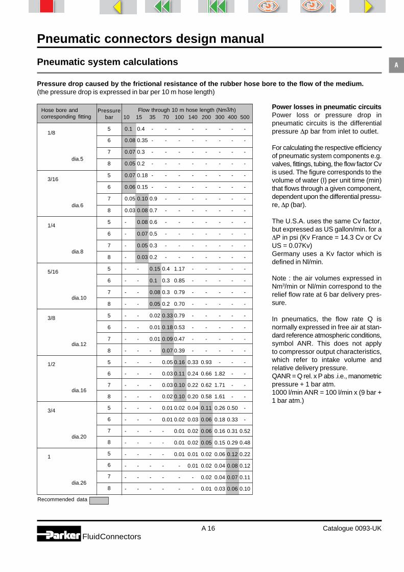
Pressure drop caused by the frictional resistance of the rubber hose bore to the flow of the medium.(the pressure drop is expressed in bar per 10 m hose length)
Power losses in pneumatic circuitsPower loss or pressure drop inpneumatic circuits is the differentialpressure ∆p bar from inlet to outlet.
For calculating the respective efficiencyof pneumatic system components e.g.valves, fittings, tubing, the flow factor Cvis used. The figure corresponds to thevolume of water (I) per unit time (min)that flows through a given component,dependent upon the differential pressu-re, ∆p (bar).
The U.S.A. uses the same Cv factor,but expressed as US gallon/min. for a∆P in psi (Kv France = 14.3 Cv or CvUS = 0.07Kv)Germany uses a Kv factor which isdefined in Nl/min.
Note : the air volumes expressed inNm3/min or Nl/min correspond to therelief flow rate at 6 bar delivery pres-sure.
In pneumatics, the flow rate Q isnormally expressed in free air at stan-dard reference atmospheric conditions,symbol ANR. This does not applyto compressor output characteristics,which refer to intake volume andrelative delivery pressure.QANR = Q rel. x P abs .i.e., manometricpressure + 1 bar atm.1000 l/min ANR = 100 l/min x (9 bar +1 bar atm.)
Hose bore andcorresponding fitting
Recommended data
1/8
dia.5
3/16
dia.6
1/4
dia.8
5/16
dia.10
3/8
dia.12
1/2
dia.16
3/4
dia.20
1
dia.26
Pressurebar
5
6
7
8
5
6
7
8
5
6
7
8
5
6
7
8
5
6
7
8
5
6
7
8
5
6
7
8
5
6
7
8
Flow through 10 m hose length (Nm3/h)10 15 35 70 100 140 200 300 400 500
0.1 0.4 - - - - - - - -
0.08 0.35 - - - - - - - -
0.07 0.3 - - - - - - - -
0.05 0.2 - - - - - - - -
0.07 0.18 - - - - - - - -
0.06 0.15 - - - - - - - -
0.05 0.10 0.9 - - - - - - -
0.03 0.08 0.7 - - - - - - -
- 0.08 0.6 - - - - - - -
- 0.07 0.5 - - - - - - -
- 0.05 0.3 - - - - - - -
- 0.03 0.2 - - - - - - -
- - 0.15 0.4 1.17 - - - - -
- - 0.1 0.3 0.85 - - - - -
- - 0.08 0.3 0.79 - - - - -
- - 0.05 0.2 0.70 - - - - -
- - 0.02 0.33 0.79 - - - - -
- - 0.01 0.18 0.53 - - - - -
- - 0.01 0.09 0.47 - - - - -
- - - 0.07 0.39 - - - - -
- - - 0.05 0.16 0.33 0.93 - - -
- - - 0.03 0.11 0.24 0.66 1.82 - -
- - - 0.03 0.10 0.22 0.62 1.71 - -
- - - 0.02 0.10 0.20 0.58 1.61 - -
- - - 0.01 0.02 0.04 0.11 0.26 0.50 -
- - - 0.01 0.02 0.03 0.06 0.18 0.33 -
- - - - 0.01 0.02 0.06 0.16 0.31 0.52
- - - - 0.01 0.02 0.05 0.15 0.29 0.48
- - - - 0.01 0.01 0.02 0.06 0.12 0.22
- - - - - 0.01 0.02 0.04 0.08 0.12
- - - - - - 0.02 0.04 0.07 0.11
- - - - - - 0.01 0.03 0.06 0.10

Pneumatic connectors design manual
A 17 Catalogue 0093-UKFluidConnectors
APneumatic system calculations
Calculation of flow rate as afunction of Cv / KvFor upstream gauge pressure of6 bar.
CvUK/USA
KvFrance
1 138
1.5 162
2 180
2.5 189
3 195
0.125 6 138
1 276
1.5 324
2 360
2.5 378
3 390
0.250 6 308
1 483
1.5 567
2 630
2.5 661
3 682
0.438 6 482
1 828
1.5 972
2 1080
2.5 1134
3 1170
0.751 6 826
1 2070
1.5 2430
2 2700
2.5 2835
3 2925
1.878 6 2065
1 6210
1.5 7290
2 8100
2.5 8500
3 8775
5.636 6 6200
0.14 2
0.28 4
0.49 7
0.84 12
2.1 30
6.3 90
KvGermany
Ql/min(ANR)∆p
Flow rate is inversely proportional topressure.In a pneumatic cylinder, for example,the pressure increases from thebeginning to the end of the stroke,whereas the flow rate decreases fromits maximum value at the beginning ofthe stroke to zero at the end of thestroke.Considering a pneumatic componentwith a specified flow factor Cv/Kv, theflow rate Q, corresponding to anydifferential pressure ∆p from inlet tooutlet is calculated using the followingequation :Q ANR = 403.3 Cv √∆p x P abs.downstreamQ = flow rate l/min free airCv or Kv = flow factor∆p = differential pressure in barP = abs. pressure downstream = abs.pressure upstream - ∆p.abs. pressure upstream =manometricpressure + 1 bar atm.
Note : this equation is applicable solong as ∆p is less than half theupstream pressure.
The figures tabulated on the left arefor air at 20°C ambient temperature,65% rel. humidity and 1013 mbaratmospheric pressure.

Pneumatic connectors design manual
A 18 Catalogue 0093-UKFluidConnectors
APneumatic system calculations
Orifice diameter for different cylinder types and speeds, for an upstream gauge pressure of 6 bar
Cylinders must never be subjected to 100% load in order to determine their efficiency (20% approx.)
Notes :1 - The total displacement time is obtained by taking the travel time and adding the damping time, the response time (table B, page 19) and thetime required for air intake into tubing beyond 1 m (table C, page 19).2 - The speed and response time of a cylinder are not constant, but totally variable dependant on a number of factors such as : the inertia of themasses to be displaced, seating and sticking effect at the start of travel, the type of cylinder construction (seals, load distribution, etc.), the condition ofthe cylinder (wear, corrosion, etc.), whether the cylinder is mounted horizontally or vertically. The maximum performance values shown are approximateonly, and are intended for the purpose of comparison. Depending on the operating conditions, these values could be reduced by half.
Valve Maximum cylinder speed attainable without braking, for tube length of 1 m (speed in mm/s)
Fitting Bore Cvthread diameter
mm
Cylinder load M5 Cylinderfitting
1/4 Cylinderfitting
1/8 Cylinderfitting
3/8 Cylinderfitting
3/4 Cylinderfitting
1/2 Cylinderfitting
M5 3 0.14
1/8 5 0.49
1/4 6 0.84
3/8
1/2 12 2.1
3/4
1 20 6.3
346 80%
405 70%
441 60%
463 50%
1211 80%
1417 70%
1543 60%
1620 50%
2076 80%
2430 70%
2646 60%
2778 50%
5190 80%
6075 70%
6615 60%
6945 50%
15570 80%
18225 70%
19845 60%
20835 50%
Critical speedarea
8 10 12 16 20 25 32 40 50 63 80 100 125 160 200
6920 4380 3062 1721 1102 705 430 275 176
8100 5127 3584 2015 1290 825 504 322 206
8820 5582 3903 2194 1404 898 549 351 225
9260 5861 4097 2303 1475 943 576 369 236
3857 2466 1506 964 617 389 241
4513 2886 1762 1128 722 455 282
4914 3143 1919 1229 786 495 307
5159 3299 2015 1290 825 520 322
1653 1058 666 413 264 169
1935 1238 780 484 310 198
2107 1348 849 527 337 216
2212 1415 892 553 354 226
1666 1033 661 423 258 165
1950 1209 774 495 302 193
2123 1317 843 539 329 211
2229 1382 885 566 346 221
775 496
907 580
988 632
1037 664

Pneumatic connectors design manual
A 19 Catalogue 0093-UKFluidConnectors
APneumatic system calculations
Cyl.dia
Fittingthread
Strokemm
Responsetime (s)
50 0.04
100 0.08
150 0.12
200 0.16
100 0.07
150 0.17
200 0.23
300 0.34
150 0.17
200 0.23
300 0.35
400 0.46
200 0.13
300 0.19
400 0.25
500 0.31
300 0.29
400 0.39
500 0.43
600 0.59
400 0.64
500 0.80
600 0.96
700 1.13
800 1.29
Cylinder response time (table B)for 80% load, gauge pressure 6 bar,tube length 1 m
The average response times showninclude an allowance for the time ta-ken to empty the tubes and restorepressure. The values given are ap-proximate only and subject to varia-tion dependent upon the conditionof the tubing and the cylinder.
Air intake time for different tube lengths and diameters (table C),gauge pressure of 6 bar
3 0.022 0.060 0.085 0.110 0.170 0.238
4 0.018 0.045 0.063 0.084 0.130 0.185
6 0.010 0.030 0.045 0.060 0.095 0.133
9 0.018 0.035 0.048 0.060 0.090 0.120
The temptation to reduce thepressure drop by choosing a largediameter tube should be resisted.Excessive over dimensioning will givean insignificant improvement inpressure drop at the expense ofwaste air and an increase inresponse time owing to the need tofill a greater volume.
160 1/2
125 1/2
100 1/2
80 3/8
50 1/4
32 1/8
Hose length in metres2 4 5 6 8 10
HoseID
mm
Time in seconds
Pneumatic connectors design manual
A 20 Catalogue 0093-UKFluidConnectors
APneumatic system calculations
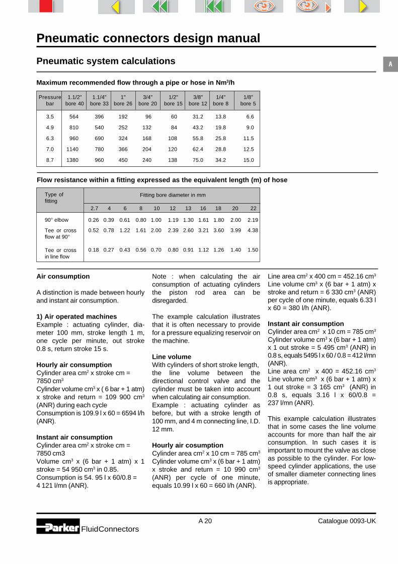
Maximum recommended flow through a pipe or hose in Nm3/h
Flow resistance within a fitting expressed as the equivalent length (m) of hose
Fitting bore diameter in mm
2.7 4 6 8 10 12 13 16 18 20 22
0.26 0.39 0.61 0.80 1.00 1.19 1.30 1.61 1.80 2.00 2.19
0.52 0.78 1.22 1.61 2.00 2.39 2.60 3.21 3.60 3.99 4.38
0.18 0.27 0.43 0.56 0.70 0.80 0.91 1.12 1.26 1.40 1.50
Type offitting
90° elbow
Tee or crossflow at 90°
Tee or crossin line flow
Pressure 1.1/2" 1.1/4" 1" 3/4" 1/2" 3/8" 1/4" 1/8"bar bore 40 bore 33 bore 26 bore 20 bore 15 bore 12 bore 8 bore 5
3.5 564 396 192 96 60 31.2 13.8 6.6
4.9 810 540 252 132 84 43.2 19.8 9.0
6.3 960 690 324 168 108 55.8 25.8 11.5
7.0 1140 780 366 204 120 62.4 28.8 12.5
8.7 1380 960 450 240 138 75.0 34.2 15.0
Air consumption
A distinction is made between hourlyand instant air consumption.
1) Air operated machinesExample : actuating cylinder, dia-meter 100 mm, stroke length 1 m,one cycle per minute, out stroke0.8 s, return stroke 15 s.
Hourly air consumptionCylinder area cm2 x stroke cm =7850 cm3
Cylinder volume cm3 x ( 6 bar + 1 atm)x stroke and return = 109 900 cm3
(ANR) during each cycleConsumption is 109.9 l x 60 = 6594 l/h(ANR).
Instant air consumptionCylinder area cm2 x stroke cm =7850 cm3Volume cm3 x (6 bar + 1 atm) x 1stroke = 54 950 cm3 in 0.85.Consumption is 54. 95 l x 60/0.8 =4 121 l/mn (ANR).
Note : when calculating the airconsumption of actuating cylindersthe piston rod area can bedisregarded.
The example calculation illustratesthat it is often necessary to providefor a pressure equalizing reservoir onthe machine.
Line volumeWith cylinders of short stroke length,the line volume between thedirectional control valve and thecylinder must be taken into accountwhen calculating air consumption.Example : actuating cylinder asbefore, but with a stroke length of100 mm, and 4 m connecting line, I.D.12 mm.
Hourly air cosumptionCylinder area cm2 x 10 cm = 785 cm3
Cylinder volume cm3 x (6 bar + 1 atm)x stroke and return = 10 990 cm3
(ANR) per cycle of one minute,equals 10.99 l x 60 = 660 l/h (ANR).
Line area cm2 x 400 cm = 452.16 cm3
Line volume cm3 x (6 bar + 1 atm) xstroke and return = 6 330 cm3 (ANR)per cycle of one minute, equals 6.33 lx 60 = 380 l/h (ANR).
Instant air consumptionCylinder area cm2 x 10 cm = 785 cm3
Cylinder volume cm3 x (6 bar + 1 atm)x 1 out stroke = 5 495 cm3 (ANR) in0.8 s, equals 5495 l x 60 / 0.8 = 412 l/mn(ANR).Line area cm2 x 400 = 452.16 cm3
Line volume cm3 x (6 bar + 1 atm) x1 out stroke = 3 165 cm3 (ANR) in0.8 s, equals 3.16 l x 60/0.8 =237 l/mn (ANR).
This example calculation illustratesthat in some cases the line volumeaccounts for more than half the airconsumption. In such cases it isimportant to mount the valve as closeas possible to the cylinder. For low-speed cylinder applications, the useof smaller diameter connecting linesis appropriate.

Pneumatic connectors design manual
A 21 Catalogue 0093-UKFluidConnectors
APneumatic system calculations
Air consumption for different pneumatic tools
2) Pneumatic power unitsAir compressors are designed withconsideration for the overall operationalrequirements, together with the airdemand of the machines and handtools.When calculating the air demand ofpneumatic hand tools, their actualworking time should be taken intoaccount. For the associated connec-ting hose the instant air consumptionis also determined.
LeakageLeakage is measured as pressuredrop in compressed air systems, andpressure increase in vacuum systems.The respective leak rates are calculatedas follows.
Units of measurement of leakage- 1 atm = 1013.10 mbar = 760 Torr- 1 atm cm3/s = 0.1 Pascal m3/s = 11 mbar l/s = 0.76 Torr l/s = 760 Lusec(litre, micron, second)
Calculating leakage in compres-sed air systemsTank volume : 1 m3
Initial pressure : 8 bar.Pressure after 12 min 30 s. = 5 barPressure drop : 8 - 5 = 3 barLeak rate = 1 m3 x 3 bar x 60/12.5equals 14.4 Nm3/h (ANR).
Calculating leakage in vacuumsystemsTank volume : 1 m3
Initial vacuum : 0.012 atm.Pressure increase : 0.008 - 0.012 =0.068 atm
Leak rate = 1 000 cm3 x 0.068 atm x60/8.5 equals 480 atm. cm3 /s.Vacuum after 8 min 30 s. : 0.08 atmPressure increase : 0.08 - 0.012 =0.068 atmLeak rate = 1 000 cm3 x 0.068 atm x60/8.5 equals 480 atm.cm3 /s
Leak detectionSoap bubble method:A hole of 2µm at a pressure of 2 barproduces a bubble of 1 mm3 perminute.Spray method :Spray type leak testers offer conve-nience and ease of application.
Tool Consumption Duty cyclem3 / h (ANR) sec
Shears 24 0.1 to 0.8
Hammer-action wrenches for :6mm bolts 17 0.1 to 0.612 mm bolts 24 0.1 to 0.616 mm bolts 27 0.1 to 0.620 mm bolts 45 0.1 to 0.633 mm bolts 66 0.1 to 0.340 mm bolts 72 0.1 to 0.3
Nibblers 24 0.5 to 0.6
Grindersdia. 100 mm 40 0.4 to 0.5dia. 150 mm 60 0.4 to 0.5
Grinders/cuttersdia. 180 mm 80 0.4 to 0.5dia. 235 mm 168 0.4 to 0.5
Drills and nut tappers6 to 8 mm 32 0.4 to 0.68 to 10 mm 35 0.4 to 0.610 to 13 mm 40 0.4 to 0.618 mm 45 0.3 to 0.722 mm 66 0.3 to 0.732 mm 114 0.3 to 0.7
Spray guns 6 to 25 0.6 to 0.9
Sanderssander dia. 127 36 0.4 to 0.5sander dia. 180 60 0.4 to 0.5
Orbital sanderswith disk 21 0.8 to 0.9with pad 21 0.8 to 0.9
Bellows (2 mm nozzle) 10 0.1 to 0.2
Screw-driving machines6 mm 23 0.1 to 0.68 mm 32 0.1 to 0.610 mm 35 0.1 to 0.6

Pneumatic connectors design manual
A 22 Catalogue 0093-UKFluidConnectors
AInstallation guidelines
Service linesSteel tubing, copper tubing or metalbraid reinforced hoses are used forthe connection of air operatedmachines to the supply network.Connecting lines of unsecuredplastic tubing is not recommended(accident hazard in the case ofpressure line pull off).Service lines - even copper - mustnot be used for earthing purposes.
Suspended pressure linesFor suspended pressure lines, theParker Push-Lok hose system offerseasy assembly and alignment,together with a vibration absorbingconnection.If the risk of hose pull-off duringoperation cannot be excluded, thehose must be secured so as toprevent dangerous whipping.
Pneumatic tubes, even if copper,should not be used for earthingpurposes.
Avoid problems of alignment and vibration by not linking machines to a jointair supply.

Pneumatic connectors design manual
A 23 Catalogue 0093-UKFluidConnectors
AInstallation guidelines
Wall-mounted pressure linesFor wall-mounted connecting lines,copper or steel tubing is preferred toflexible hoses which tend to chafeagainst the wall.The line is fixed to the wall with tubeclamps approx 1 m apart.
High temperature or high vibra-tion environmentIn a high temperature or high vibra-tion environment, the use of hose isrecommended.
Parker tube fittings simplify theinstallation of connections betweenair operated machinery and supplynetworks, and facilitate, in parti-cular, transition from copper toplastic tubing or pressure hoses.
Shut-off and unloading valveA shut-off and unloading valve is "inline" mounted at the inlet of eachair operated machine. A silencerand pressure relief device shouldbe mounted on the outlet of theunloading valve.
Open Closed
ClosedOpen
Pneumatic connectors design manual
A 24 Catalogue 0093-UKFluidConnectors
AInstallation guidelines
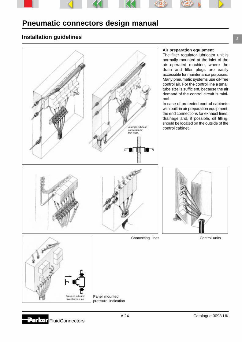
Air preparation equipmentThe filter regulator lubricator unit isnormally mounted at the inlet of theair operated machine, where thedrain and filler plugs are easilyaccessible for maintenance purposes.Many pneumatic systems use oil-freecontrol air. For the control line a smalltube size is sufficient, because the airdemand of the control circuit is mini-mal.In case of protected control cabinetswith built-in air preparation equipment,the end connections for exhaust lines,drainage and, if possible, oil filling,should be located on the outside of thecontrol cabinet.
Panel mountedpressure indication
Connecting lines Control units
Pressure indicatormounted on a tee
A simple bulkheadconnection forthin walls.
Pneumatic connectors design manual
A 25 Catalogue 0093-UKFluidConnectors
AInstallation guidelines
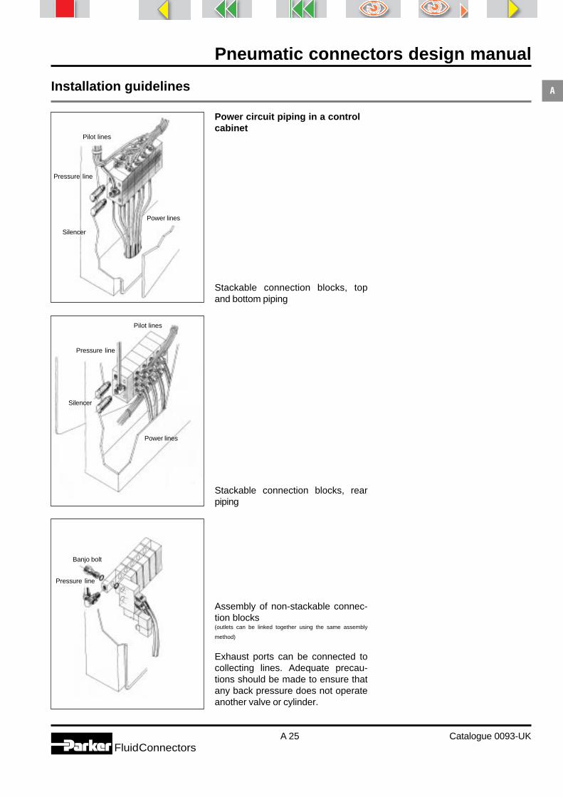
Power circuit piping in a controlcabinet
Stackable connection blocks, topand bottom piping
Stackable connection blocks, rearpiping
Assembly of non-stackable connec-tion blocks(outlets can be linked together using the same assembly
method)
Exhaust ports can be connected tocollecting lines. Adequate precau-tions should be made to ensure thatany back pressure does not operateanother valve or cylinder.
Pilot lines
Silencer
Pressure line
Power lines
Silencer
Pressure line
Pilot lines
Power lines
Banjo bolt
Pressure line

Pneumatic connectors design manual
A 26 Catalogue 0093-UKFluidConnectors
APneumatic control
Mounting on cylinder Installation in line or where it is difficult toobtain access to the cylinder for adjustment
For control of inlet air on mini cylinders
Pneumatic integrated fittingsFlow control valvesPneumatic integrated regulators aredesigned for direct mounting ontocylinder ports, securing accuratecontrol of the exhaust air flow fromthe cylinder, and precise adjustmentof piston-rod speed. Their usepermits easier piping and a morecompact installation.
Pneumatic cylindersService lines for pneumatic cylindersare made using fibre-braid reinforcedhose (accident protection in case ofpull-off during operation) or flexiblepolyamide or polyurethane tubing.Areas exposed to heavy chafingshould be sleeved.
For interconnections between pneu-matic cylinders and air-oil reservoirs,polyamide or polyurethane tubing ofappropriate pressure rating should beused. Where air-oil intensifiers areused, pipework should be copper ( novolume expansion during operationalpressure surges).

Pneumatic connectors design manual
A 27 Catalogue 0093-UKFluidConnectors
APneumatic control
Prestobloc check valvesPneumatically controlled Prestobloccheck valves are designed for directmounting onto cylinder ports, and as-sure the quick stopping of the piston-rod by blocking the cylinder supplyand exhaust.The two direction valve is normallyopen. It closes when the control pres-sure is cut off, as well as in the eventof an air failure.
Prestobloc fittings are used, inparticular, as safety stops to preventdescent under load in the event of apower failure, and as safety locksassociated with emergency switches.
Prestoload exhaust valvesPneumatically controlled Prestoloadexhaust valves are designed for di-rect mounting onto cylinder portsand provide a quick discharge of the
cylinder chambers upon receipt of apilot signal. The valve closes whenthe control pressure is cut off.
Prestosil silencers and flow controlvalves
Integrated Prestosil components aredesigned for direct mounting onto theexhaust port of single acting cylindersand directional control valves.
They provide efficient silencing ofexhaust noise and permit preciseadjustment of piston-rod speed.

Pneumatic connectors design manual
A 28 Catalogue 0093-UKFluidConnectors
AConnectors for pneumatic systems
The large variety of pneumatic applications has led to the development of fittings to meet these requirements.
There are 3 major fitting styles:
- Push-in fittings for application with flexible tubing and pressures up to 25 bar.- Compression fittings for applications with copper and flexible tubing. For pressures up to 180 bar.- Push-on fittings suitable for use with flexible tubing and pressures up to 40 bar.
Parker offers a complete fitting package for pneumatic applications.
Prestoweld 2 push-in fittingsPrestoweld 2 brass push-in fittings areused with Prestoweld 2 sparkresistant tubing for weldingapplications. Suitable for use fromprimary vacuum to 25 bar andtemperatures up to 100° C.
Prestolok micro push-in fittings
Prestolok micro push in fittings aredesigned for use where space is at apremium.
They are designed for use withplastic tubing from primary vacuumto 16 bar, and temperatures up to80°C.
Prestolok push-in fittings
Prestolok push-in brass fittings aresuitable for plastic tubing fromprimary vacuum to 25 bar, andtemperatures up to 100°C
Prestolok 2 push-in fittingsPrestolok 2 push-in fittings aremanufactured from glass reinforcednylon bodies and nickel plated brassstud terminations. They are designedfor use with plastic tubing fromprimary vacuum to 18 bar, andtemperatures up to 80° C.
Application examples:- Textile machinery- Packaging equipment- Cutting oils- Robots
Application examples:- Transfer lines- Compressors- Climate control
Application examples:- Welding guns- Welding fixtures- Spot welding machines
Application examples:- Miniature cylinders- Miniature pneumatics

Pneumatic connectors design manual
A 29 Catalogue 0093-UKFluidConnectors
AConnectors for pneumatic systems
Metrulok brass fittingsThese bite type fittings are suitable forcopper tubing up to 180 bar and polya-mide tubing up to 42 bar pressure, andtemperatures up to 190°C.
Application examples : Compres-sors, Pneumatic hand tools, Lubri-cation systems, Automotive auxiliarysystems.
PL nickel plated brass fittingsPL two-piece fully reusable nickelplated brass fittings for use withplastic tubing.They can be assembled by handwith polyurethane tubing.Suitable for pressures up to 40 barand temperatures up to 100°C.
Application examples :Laboratory equipment, Pneumatichand tools, Pressure washers,Packaging machinery.
Brass adaptorsA comprehensive range of adaptorsfor pneumatic and low pressure fluidapplications. Available with BSPP,metric and NPT threads they maybe used from primary vacuum to60 bar.
Ball ValvesSuitable for many fluid applications.Parker’s range of BSPP threadedball valves include short and longthread options, mini barstock valvesand padlockable valves in sizes upto 2” BSPP.
Ermeto original - Bite Type HighPressure Tube Fitting Systems- EO-2 Dry Technology : Steel with
NBR sealing for steel tubing orStainless steel 1.4571 with FPMsealing for stainless steel tubing.
- DPR Progressive Ring : Steel orStainless Steel 1.4571 for Steel orStainless Steel tubing.
- D Cutting Ring : Brass for copper orpolyamide tubing.
Application examples : Compressors,Machine tools, Handling Equipment,Injection Moulding.
Pneumatic Quick couplersBrass and steel pneumatic quickcouplings meeting ISO 6150-B,ISO 6150-C or “Europrofile”. Availablewith different end configurations and flowperformance up to 3500 l/min, theycan be used for : grinding machines,pneumatic wrenches, tools currentlyutilised in industry and garages, and alsofor many other applications.
Blow gunsImpact resistant plastic blow gunsavailable with a variety of nozzleconfigurations with or without safetyvalving. They can be used at all themanufacturing stages to : blow offparts, clean work-stations, removedust, dry.
1
2
1
1
2
21
2

Pneumatic connectors design manual
A 30 Catalogue 0093-UKFluidConnectors
ATerms used in pneumatics
Absolute pressure Pressure measured fromabsolute zero.
Absolute temperature Temperature measuredabove absolute zero.
Actuator A pneumatic devicewhich is used to applypower, e.g. a lever,solenoid or cylinder.
Adiabatic expansion The expansion orcompression of a gaswithout change in heatcontent.
Aftercooling Removal of heat from airafter compression iscomplete.
Air receiver A pressure vessel in whichcompressed air is stored.
Ambient temperature Temperature of theenvironment.
Atmospheric pressure The absolute pressure ofthe atmosphere asmeasured for a givenaltitude.
Capacity (compressor) Actual volume rate offlow, compressed anddelivered at the dischargepoint, at stated inletconditions.
Closed loop system A pneumatic circuit,whereby, air from theactuators is returned as aclosed pressurised circuitto the compressor inlet.
Compression ratio Ratio of final pressure tooriginal pressure.
Compressor A machine which causesa gas to flow against apressure thus convertingmechanical force andmotion into pneumaticfluid power.
Compressor regulator A device fitted to acompressor which controlsthe output of the machine.
Condensate Liquid formed by thecondensation of watervapour in the air, due toa fall in temperature.
Discharge temperature Temperature at thestandard discharge pointof a compressor.
Displacement The volume displacedby the compressionelement in a given time.
Dryer Equipment used to reducethe water vapour content ofcompressed air.
Fusible plug Fitted to the hot dischargezone of a compressor forprotection againstexcessively hightemperatures.
Gauge pressure Pressure measuredabove or belowatmospheric pressure.
Inlet temperature Temperature at thestandard inlet point ofthe compressor.
Intercooling The cooling of compressedair between compressionstages.
Isothermal expansion Expansion or compressionwithout change oftemperature.
Multi-stage Two or more stages ofcompression compression, with
intercooling betweenthem, before the finalpressure is reached.
Lubricator Equipment used torelease a controlledamount of lubricant intothe compressed airstream.

Pneumatic connectors design manual
A 31 Catalogue 0093-UKFluidConnectors
A
Overall stage ratio The pressure ratio for anyparticular pressure stage ina multi-stage compressor.
Pressure ratio (total) The ratio between theabsolute dischargepressure and theabsolute inlet pressure.
Pressure regulator A valve or similar devicefor reducing line pressureto a lower constant value.
Pressure relief valve A valve used to limit themaximum system pressure,exhausting the compressedair to atmosphere when therequired back pressure isexceeded.
Pulsation dampener A chamber fitted at theinlet or discharge of areciprocating compressorto remove pulsations andto prevent resonance.
Ring main A compressed air orvacuum main whichbegins and ends at thecompressor, or vacuumpump providing everyoutlet which two possiblesources of supply.
Separator A device for removingliquids from compressedair.
Single-stage Initial to final pressure incompression a single step.
Specific energy Input energy requirementrequirement or power per unit of compressedconsumption air produced ; or shaft
input power per unit ofcompressor capacity.
Standard reference The agreed atmosphereatmosphere to which specification,
valves and test results aredetermined in otheratmospheres, are corrected.
Volumetric efficiency Ratio of capacity todisplacement of acompressor or vacuumpump.
Terms used in pneumatics

Pneumatic connectors design manual
A 32 Catalogue 0093-UKFluidConnectors
APneumatic symbols
For the design of pneumatic systems a range of standard symbols is used to represent the separate componentsused in the system.
These symbols are defined in ISO 1219, BS 2917 and NFEO4 - 057
Valve symbols
1
2
1
2
13
2
13
2
13
4 2
3 1
4 2
1
2
3
4
5
1
2
3
4
5
1
2
3
4
5
1
2
3
4
5
Valve type Normal position Description of valve Symbol
2/2 Closed Two port (2 way)Two position(No exhaust port)
2/2 Open Two port (2-way)Two position(No exhaust port)
3/2 Closed Three port (3-way)Two position
3/2 Open Three port (3-way)Two position
4/2 1 line, for air inlet Four port (4-way)1 line, for exhaust Two position
4/3 Neutral mid-position Four port (4-way)(all ports closed) Three position
5/2 1 line, for air inlet Five port (4-way)1 line, for exhaust Two position2 separate exhaustswhich can berestricted separately.
5/3 (X) Neutral mid-position Five port (4-way)(all ports closed) Three position
5/3 (Y) Negative mid- Five port (4-way)position inlet, Three positionclosed cylinder ports,open exhaust ports.
5/3 (Z) Positive mid- Five port (4-way)position cylinder, Three positionports open to air inlet.

Pneumatic connectors design manual
A 33 Catalogue 0093-UKFluidConnectors
APneumatic symbols
Methods of valve actuation
Flow Control Valves
Non-Return Valves, Shuttle Valves, Quick Exhaust Valves
Description of actuation Symbol
Muscular actuation : General symbol (without indication of control type)
- by push button
- by lever
- by pedal
Mechanical actuation :
- by plunger or tracer
- by spring
- by roller
- by roller, operating in one direction only.
Description
Throttle valve Simplified symbol (Does not indicate thecontrol method or the state of the valve)
Flow control valve Valve allows free flow in one directionbut restricted flow in the other.
Symbol
Non-return valve :
- free Opens if the inlet pressure is higherthan the outlet pressure.
- spring loaded Opens if the inlet pressure is greater than theoutlet pressure plus the spring pressure.
Shuttle valve The inlet port connected to the higherpressure is automatically connectedto the outlet port while the other inletport is closed.
Quick exhaust valve When the inlet port is unloaded theoutlet port is freely exhausted.
Description of valves Symbol

Pneumatic connectors design manual
A 34 Catalogue 0093-UKFluidConnectors
APneumatic symbols
Pneumatic cylinders
Description Symbol
Pressure source Simplified general symbol
Electric motor
Flow lines and connections
Flow line :- working line, return line and feed line
- pilot control line
- drain or bleed line
- flexible pipe Flexible hose, usually connectingmoving parts
- electric line
Single-acting cylinder Cylinder in which the air pressureoperates in one direction only.
- push type
- pull type
Double acting Cylinder in which the air pressurecylinder operates alternately in both directions
(forward and backward strokes)
- with single piston rod
- with double-ended piston rod (though rod)
Cylinder with cushion :
- with double fixed cushion
- with double adjustable cushion
Description Symbol
M
Sources of Energy

Pneumatic connectors design manual
A 35 Catalogue 0093-UKFluidConnectors
APopular Coupling Designs
Parker’s Quick Coupling Division manufactures quick couplings to interchange with popular designs that have becomeaccepted standards in the industry today.The actual size chart below can be used to help select Parker Quick Couplings that will interchange with specific nippledesigns sizes and performance data.
3/8“ Body Size
550
900
2350
9001000 970
800
3500
1700
3500
1800
1/4“ Body Size
10 mm Body Size
1/4“ Body Size
7.2 mm Body Size
1/2“ Body Size
FLO
W R
ATE
(L/M
IN)
35
20
16
15
● ●
●
●
●
●
Max
. ope
ratin
gpr
essu
re(b
ar)
ISO 6150-BSTANDARD
SERIESPB Series
1/4”-3/8”-1/2”
PBF Series
1/4”
EZ Series
1/4”-3/8”-1/2”
PE Series
7.2 mm
PEF Series
7.2 mm - 10 mm
PCF Series
1/4”
ISO 6150-CEUROPROFILE
MA
LE T
IP A
CTU
AL
SIZE

Prestolok 2Push-in fitting
Catalogue 3528-2-UK

Prestolok 2 push-in fitting
B 2 Catalogue 3528-2-UKFluidConnectors
B
IndexStraightconnectors
90° elbows
adjustable extendedmale - BSPTC63LPK - p. B 8
adjustable male -BSPTC63PK - p. B 8
adjustable maleBSPPC64PK- p. B 9
Tees
Y connectors
unionEPK - p. B 10
unionHPK - p. B 7
unequal unionHPK - p. B 7
male - metricF8PB - p. B 7
compact adjustablemale - BSPTC63SPK - p. B 8
compact plug-inT2ESPK - p. B 10
adjustable bulkheadunionWE6PK - p. B 10
male - BSPTF3PB - p. B 6
male - BSPPF4PB - p. B 6
female - BSPPG4PB - p. B 7
adjustable malerun - BSPTR63PK - p. B 11
adjustable malerun -BSPPR64PK - p. B 11
unionJPK - p. B 10
unequal unionJPK - p. B 11
double unionYJ5PK - p. B 14
adjustable maleBSPTYJ63PK - p. B 15
adjustable malebranch - BSPTS63PK - p. B 13
plug-in branchT2JPK - p. B 12
plug-in runT2JJPK - p. B 12
adjustable malebranch - metricS68PK - p. B 13
adjustable malebranch - BSPPS64PK - p. B 13
compact adjustablemale - BSPPC64SPK - p. B 9
compact adjustablemale - metricC68SPK - p. B 9
adjustable male -metricC68PK - p. B 9
adjustable malerun - metricR68PK - p. B 12
plug-in doubleYJ52PK - p. B 15
double union adjustablemale - BSPPYJ564PK - p. B 15
plug-inYJ2PK - p. B 14
unequal unionYJPK - p. B 14
unionYJPK - p. B 14
adjustable malebulkheadWYJ6PK - p. B 14
adjustable maleBSPPYJ64PK - p. B 16
double union adjustablemale - BSPTYJ563PK - p. B 15
Prestolok 2 push-in fitting
B 3 Catalogue 3528-2-UKFluidConnectors
B
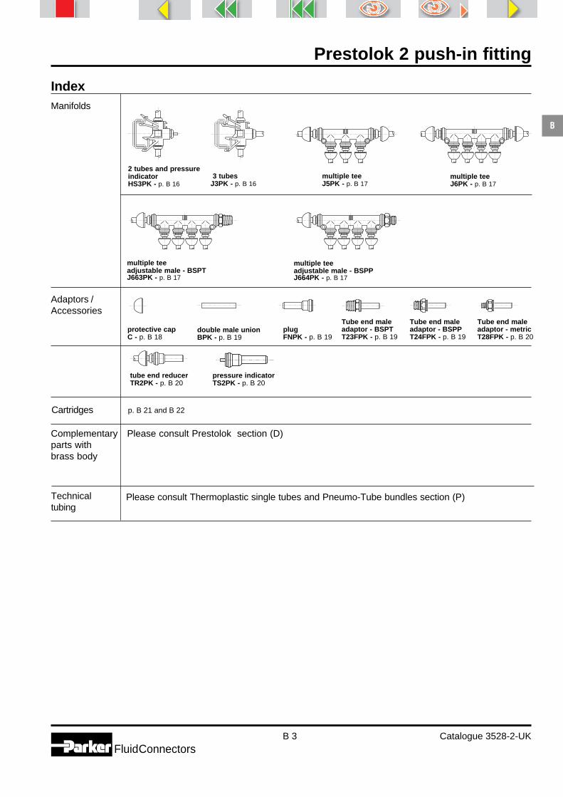
IndexManifolds
multiple teeJ5PK - p. B 17
2 tubes and pressureindicatorHS3PK - p. B 16
3 tubesJ3PK - p. B 16
multiple teeJ6PK - p. B 17
Adaptors /Accessories
Cartridges p. B 21 and B 22
Complementary Please consult Prestolok section (D)parts withbrass body
Technical Please consult Thermoplastic single tubes and Pneumo-Tube bundles section (P)tubing
multiple teeadjustable male - BSPTJ663PK - p. B 17
multiple teeadjustable male - BSPPJ664PK - p. B 17
pressure indicatorTS2PK - p. B 20
tube end reducerTR2PK - p. B 20
plugFNPK - p. B 19
protective capC - p. B 18
double male unionBPK - p. B 19
Tube end maleadaptor - BSPTT23FPK - p. B 19
Tube end maleadaptor - BSPPT24FPK - p. B 19
Tube end maleadaptor - metricT28FPK - p. B 20

Prestolok 2 push-in fitting
B 4 Catalogue 3528-2-UKFluidConnectors
B
From 0.01to
18 bar
From - 25° Cto
+ 80° C
For a number of years Parker Hannifin has designedand manufactured push-in fittings recognised worldwidefor their quality and reliability.The new generation Prestolok 2 has been developed toprovide even better technical features for the end user.
With this additional new product, Parker provides thesolutions in many fields and applications.
Prestolok 2 uses “elastic teeth” grab ring technology,invented and perfected by Parker, who guarantee itsexcellent tube retention qualities.
Prestolok 2 can be used with most types of plastictubing available on the market (see Thermoplastic singletube and Pneumo-Tube bundles section - P*), offeringsignificant advantages to the user.* For other materials, please consult us.
Principle
Technical features
ApplicationsPerfectly adapted for use withpneumatic systems in a largevariety of industries, Prestolok 2 isalso designed to handle many otherfluids (please consult us) thuscovering a wide range ofapplications.
1
2
Working Workingpressure temperature
Prestolok 2 : push-in fitting for pneumatic applications
53467
8
Food industrie
Machine tools
Textile
Packaging
Robotics
Material1 2 3 4 5 6 7 8
Body Threaded Sleeve Grab ring Push Back-up O-ring Protectivestraight connectors button washer cap
Polyamide HR Nickel Nickel Stainless Polyacetal Brass Nitrile Polyacetalplated plated steelbrass brass

Prestolok 2 push-in fitting
B 5 Catalogue 3528-2-UKFluidConnectors
B
Advantages
Ready-to-use compact fittingWide product range covering all applicationsFull flow capability
Protective capThe design of the Prestolok 2thermoplastic range permits the useof a protective cap for followingfunctions :• protection : prevents the ingress of
dirt into the connection system,• safety: eliminates the risk of
accidental disconnnection, as thepush-button is made inaccessible,
• identification :- colour coding allows identification
of fluid lines,- tube sizes are marked on the
protective cap.
High resistance polyamide bodyThe use of UV-resistant reinforcedpolyamide provides :- weight saving,- excellent mechanical performance,- compact design.The three grooves facilitate handlingand positioning of elbows and tees.A long service life is ensured by thecorrosion free body material.
Ready-to-use fittingThe Prestolok 2 range is manu-factured with brass nickel platedmale threads ready for use :- parallel threads are supplied with
a pre-assembled, fully retainedO-ring seal,
- taper threads are treated with aspecial PTFE for self sealing onassembly, reusable up to fivetimes without additional sealingmaterial.
Positive hold by a flexible grabring- the special shape of the radial
teeth grab ring prevents long-ditudinal scratch marks on thetube.
- the elasticity of the grab ringabsorbs vibration and pulsatingpressure.
- a twist-free assembly, the tube canrotate freely even under pressure.
Plastic push button- simple manual pressure on the
user friendly push button allowsinstant disconnection of the tube.
- tube sizes are marked on the pushbutton for easy identification.
How to use
Positive O-ring sealing- the smooth unmarked tube is in
direct contact with the nitrileO-ring, giving a positive seal.
- a unique back-up washer retainsthe O-ring in the optimum sealingposition, protects it from the grabring, and prevents extrusion underpressure.
Assembly- Cut the tube square.- Insert the tube into the fitting until it bottoms.
Disassembly- Simply press on the push button and withdraw the
tube

Prestolok 2 push-in fitting
B 6 Catalogue 3528-2-UKFluidConnectors
B
F3PB - Male connector - BSPT
1 A Part number C4 L P H. WeightInt. g.
F4PB - Male connector - BSPP
1 B Part number C4 J L H. WeightInt. g.
4 1/8 F4PB4-1/8 13 6 21.7 3 164 1/4 F4PB4-1/4 16 9 23.3 3 276 1/8 F4PB6-1/8 13 6 25.3 4 176 1/4 F4PB6-1/4 16 9 26.0 4 418 1/8 F4PB8-1/8* 14 6 27.4 4 24
8 1/4 F4PB8-1/4 16 9 27.4 6 298 3/8 F4PB8-3/8 20 9 28.0 6 59
10 1/4 F4PB10-1/4 17 9 35.4 6 5010 3/8 F4PB10-3/8 20 9 31.4 8 3910 1/2 F4PB10-1/2 24 12 30.3 8 60
12 1/4 F4PB12-1/4 20 9 36.0 6 4912 3/8 F4PB12-3/8* 20 9 35.7 8 4912 1/2 F4PB12-1/2 24 12 34.1 10 7214 3/8 F4PB14-3/8 22 9 38.3 8 66
14 1/2 F4PB14-1/2 24 12 37.4 10 81
* no protective cap facility
L
C4
PTFE
1 A
P
C 4J
1 B
L
Threads are treated with PTFEsealing material
4 1/8 F3PB4-1/8 12 20.5 7.5 3 144 1/4 F3PB4-1/4 14 23.0 11.0 3 215 1/8 F3PB5-1/8 11 22.5 17.5 4 135 1/4 F3PB5-1/4 14 24.0 11.0 4 176 1/8 F3PB6-1/8 14 24.0 7.5 4 19
6 1/4 F3PB6-1/4 14 24.0 11.0 4 228 1/8 F3PB8-1/8 17 28.0 7.5 4 318 1/4 F3PB8-1/4 17 28.5 11.0 4 318 3/8 F3PB8-3/8 17 26.5 11.5 6 28
10 1/4 F3PB10-1/4 19 35.5 11.0 6 45
10 3/8 F3PB10-3/8 19 33.0 11.5 8 4810 1/2 F3PB10-1/2 22 31.0 15.0 8 4712 1/4 F3PB12-1/4 22 36.5 11.0 6 6812 3/8 F3PB12-3/8 22 36.0 11.5 10 4812 1/2 F3PB12-1/2 22 36.0 15.0 10 56
14 3/8 F3PB14-3/8 24 39.0 11.5 10 9114 1/2 F3PB14-1/2 24 37.0 15.0 11 83
All straight male connectors have an internalhexagon for use with an Allen key to allow thefitting to be mounted in any position. This alsopermits close porting not possible when aspanner is used.

Prestolok 2 push-in fitting
B 7 Catalogue 3528-2-UKFluidConnectors
B
1 B Part number C4 J L Weightg.
4 1/8 G4PB4-1/8 14 9.5 26.0 226 1/8 G4PB6-1/8 14 9.5 27.5 216 1/4 G4PB6-1/4 17 14.0 33.0 228 1/8 G4PB8-1/8 17 9.5 29.0 448 1/4 G4PB8-1/4 17 14.0 33.0 29
1 Part number L O Weight g.
4 HPK4 33.5 13 56 HPK6 37.0 15 68 HPK8 39.0 17 10
10 HPK10 48.0 21 1512 HPK12 49.0 23 21
14 HPK14 54.0 25 30
HPK - Equal union
1 2 Part number L O Weightg.
6 4 HPK6-4 36.0 15 88 4 HPK8-4 38.0 17 148 6 HPK8-6 39.0 17 12
10 6 HPK10-6 47.0 21 2110 8 HPK10-8 47.0 21 19
12 10 HPK12-10 49.5 23 26
HPK - Unequal union
F8PB - Male connector - metric straight thread
1 B Part number C4 J L H. WeightInt. g.
4 M5x0.8 F8PB4M5 12 5 25.5 2.5 164 M10x1 F8PB4M10 14 8 24.0 3.0 176 M5x0.8 F8PB6M5 14 5 26.0 2.5 176 M10x1 F8PB6M10 14 8 28.0 4.0 176 M12x1.5 F8PB6M12 17 10 30.0 4.0 23
8 M12x1.5 F8PB8M12 17 10 30.0 6.0 258 M16x1.5 F8PB8M16 22 10 28.0 6.0 348 M22x1.5 F8PB8M22 27 12 30.0 6.0 55
1
L
JC 4
B
L
C 4
1 B
J
O
L
1
O2
L
1
G4PB - Female connector - BSPP

Prestolok 2 push-in fitting
B 8 Catalogue 3528-2-UKFluidConnectors
B
Dimensions shown may be changed at any time without prior notice.
C63LPK - Adjustable extended male elbow - BSPT
C63PK - Adjustable male elbow - BSPT
C63SPK - Compact adjustable male elbow - BSPT
1 A Part number C4 H M O P Weightg.
4 1/8 C63SPK4-1/8 10 14.5 20.5 13 6.5 94 1/4 C63SPK4-1/4 14 14.5 20.5 13 10.0 186 1/8 C63SPK6-1/8 11 16.5 23.0 15 6.5 146 1/4 C63SPK6-1/4 14 16.0 23.0 15 10.0 218 1/8 C63SPK8-1/8 14 19.5 25.0 17 6.5 15
8 1/4 C63SPK8-1/4 14 18.5 25.0 17 10.0 258 3/8 C63SPK8-3/8 17 18.5 25.0 17 10.0 28
10 1/4 C63SPK10-1/4 17 23.0 31.0 21 10.0 3010 3/8 C63SPK10-3/8 17 22.5 31.0 21 10.0 3610 1/2 C63SPK10-1/2 22 24.0 31.0 21 12.5 45
1 3 A Part number C4 M N O P Width Weightdia. Q g.
4 3.2 1/8 C63PK4-1/8 10 18.0 25.5 13 7.5 15.0 124 3.2 1/4 C63PK4-1/4 14 18.0 29.0 13 11.0 15.0 206 4.2 1/8 C63PK6-1/8 11 20.5 27.0 15 7.5 17.0 136 4.2 1/4 C63PK6-1/4 14 20.5 30.5 15 11.0 17.0 238 4.2 1/8 C63PK8-1/8 14 22.5 29.5 17 7.5 19.0 20
8 4.2 1/4 C63PK8-1/4 14 22.5 32.5 17 11.0 19.0 278 4.2 3/8 C63PK8-3/8 17 22.5 34.0 17 11.5 19.0 38
10 4.2 1/4 C63PK10-1/4 17 28.5 40.0 21 11.0 23.5 3710 4.2 3/8 C63PK10-3/8 17 28.5 39.0 21 11.5 23.5 4310 4.2 1/2 C63PK10-1/2 22 28.5 42.0 21 15.0 23.5 63
12 4.2 1/4 C63PK12-1/4 19 30.0 41.5 23 11.0 25.5 5512 4.2 3/8 C63PK12-3/8 19 30.0 41.0 23 11.5 25.5 5912 4.2 1/2 C63PK12-1/2 22 30.0 44.5 23 15.0 25.5 6814 4.2 3/8 C63PK14-3/8 22 33.5 45.5 25 11.5 27.5 6814 4.2 1/2 C63PK14-1/2 22 33.5 48.0 25 15.0 27.5 78
1 3 A Part number C4 M N O P Width Weightdia. Q g.
4 3.2 1/8 C63LPK4-1/8 10 18.0 41.0 13 7.5 15 224 3.2 1/4 C63LPK4-1/4 14 18.0 45.0 13 11.0 15 466 4.2 1/8 C63LPK6-1/8 11 20.5 45.0 15 7.5 17 286 4.2 1/4 C63LPK6-1/4 14 20.5 49.0 15 11.0 17 488 4.2 1/8 C63LPK8-1/8 14 22.5 49.5 17 7.5 19 46
8 4.2 1/4 C63LPK8-1/4 14 22.5 52.0 17 11.0 19 51
Our fittings are supplied without cap. See page-B 18
For product availability please consult our price list 0093-UK.
1
M
O
N
P
C4
PTFE
A
ø 3xQ
1
M
O
N
PC4
PTFE
A
ø 3xQ
O
M
1 H
PC4
PTFE
A
Threads are treated with PTFE sealing material
Threads are treated with PTFE sealing material
Threads are treated with PTFE sealing material

Prestolok 2 push-in fitting
B 9 Catalogue 3528-2-UKFluidConnectors
B
Dimensions shown may be changed at any time without prior notice.
Our fittings are supplied without cap. See page-B 18
C64PK - Adjustable male elbow - BSPP
1 B Part number C4 H J M O Weightg.
4 1/8 C64SPK4-1/8 14 16.7 6 20.5 13 164 1/4 C64SPK4-1/4 19 17.4 9 20.5 13 286 1/8 C64SPK6-1/8 14 17.9 6 23.0 15 156 1/4 C64SPK6-1/4 19 19.4 9 23.0 15 298 1/8 C64SPK8-1/8 14 18.9 6 25.0 17 18
8 1/4 C64SPK8-1/4 19 20.4 9 25.0 17 328 3/8 C64SPK8-3/8 22 21.9 9 25.0 17 42
C64SPK - Compact adjustable male elbow - BSPP
1 3 B Part number C4 J M N O Width Weightdia. Q g.
4 3.2 M3x0.5 C68PK4M3 10 3.5 18.0 22.0 13 15.0 94 3.2 M5x0.8 C68PK4M5 10 5.0 18.0 23.5 13 15.0 106 4.2 M5x0.8 C68PK6M5 11 5.0 20.5 25.0 15 17.0 128 4.2 M12x1.5 C68PK8M12 17 10.0 22.5 35.0 17 19.0 348 4.2 M16x1.5 C68PK8M16 22 10.0 22.5 35.0 17 19.0 43
8 4.2 M22x1.5 C68PK8M22 27 12.0 22.5 39.0 17 19.0 9110 4.2 M12x1.5 C68PK10M12 17 10.0 28.5 40.0 19 23.5 55
C68PK - Adjustable male elbow - metric straight thread
1 B Part number C4 H J M O Weightg.
4 M5x0.8 C68SPK4M5 10 15.5 5 20.5 13 6
C68SPK - Compact adjustable male elbow - metric straight
For product availability please consult our price list 0093-UK.
1
M
O
J
N
C4
B
ø 3xQ
O
M
1 H
JC 4
B
1
M
O
N
JC4
B
ø 3xQ
O
M
1H
JC 4
B
1 3 B Part number C4 J M N O Width Weightdia. Q g.
4 3.2 1/8 C64PK4-1/8 14 6 18.0 25.5 13 15.0 164 3.2 1/4 C64PK4-1/4 19 9 18.0 30.5 13 15.0 316 4.2 1/8 C64PK6-1/8 14 6 20.5 27.0 15 17.0 186 4.2 1/4 C64PK6-1/4 19 9 20.5 32.0 15 17.0 298 4.2 1/8 C64PK8-1/8 14 6 22.5 29.0 17 19.0 22
8 4.2 1/4 C64PK8-1/4 19 9 22.5 34.0 17 19.0 358 4.2 3/8 C64PK8-3/8 22 9 22.5 35.0 17 19.0 49
10 4.2 1/4 C64PK10-1/4 19 9 28.5 39.0 21 23.5 4510 4.2 3/8 C64PK10-3/8 22 9 28.5 40.0 21 23.5 6012 4.2 1/4 C64PK12-1/4 19 9 30.0 40.5 23 25.5 56
12 4.2 3/8 C64PK12-3/8 22 9 30.0 41.5 23 25.5 6014 4.2 3/8 C64PK14-3/8 22 9 33.5 45.0 25 27.5 7414 4.2 1/2 C64PK14-1/2 27 12 33.5 49.5 25 27.5 103

Prestolok 2 push-in fitting
B 10 Catalogue 3528-2-UKFluidConnectors
B
EPK - Equal union elbow
1 3 Part number M O Width Weightdia. Q g.
4 3.2 EPK4 18.0 13 15.0 66 4.2 EPK6 20.5 15 17.0 78 4.2 EPK8 22.5 17 19.0 10
10 4.2 EPK10 28.5 21 23.5 1712 4.2 EPK12 30.0 23 25.5 23
14 4.2 EPK14 33.5 25 27.5 31
1 2 Part number H H1 H2 M O Weightg.
4 4 T2ESPK4 31 8.5 19 20.5 13 46 6 T2ESPK6 36 11.5 22 23.0 15 54 6 T2ESPK4-6 33 9.5 19 23.0 15 58 8 T2ESPK8 38 11.0 22 25.0 17 8
T2ESPK - Compact plug-in elbow
WE6PK - 90° adjustable bulkhead union elbow
1 3 B Part number C C4 L L1 M O Width W Weightdia. Q Max. g.
4 3.2 M11x0.75 WE6PK4 14 16 37 18.0 18.0 11.5 15.0 6 226 4.2 M13x1 WE6PK6 17 17 39 19.5 20.5 13.5 17.0 6 388 4.2 M15x1.25 WE6PK8 19 19 43 21.5 22.5 15.5 19.0 6 52
10 4.2 M18x1 WE6PK10 22 22 54 29.0 28.5 18.5 23.5 8 10712 4.2 M23x1.5 WE6PK12 27 27 59 30.0 30.0 23.5 25.5 10 139
JPK - Equal union tee
1 3 Part number L M O Width Weightdia. Q g.
4 3.2 JPK4 36 18.0 13 15.0 86 4.2 JPK6 41 20.5 15 17.0 98 4.2 JPK8 45 22.5 17 19.0 14
10 4.2 JPK10 57 28.5 21 23.5 2412 4.2 JPK12 60 30.0 23 25.5 33
14 4.2 JPK14 67 33.5 25 27.5 45
O
M
H2
H
1
2H1
O
M
M
1
ø 3xQ
1
M
L1
B
O
L
C4
CW
ø 3xQ
M
M
O 1
M
L
ø 3xQ

Prestolok 2 push-in fitting
B 11 Catalogue 3528-2-UKFluidConnectors
B
Dimensions shown may be changed at any time without prior notice.
R63PK - Adjustable male run tee - BSPT
1 3 B Part number C4 J M N O Width Weightdia. Q g.
4 3.2 1/8 R64PK4-1/8 14 6 18.0 25.5 13 15.0 184 3.2 1/4 R64PK4-1/4 19 9 18.0 30.5 13 15.0 346 4.2 1/8 R64PK6-1/8 14 6 20.5 27.0 15 17.0 216 4.2 1/4 R64PK6-1/4 19 9 20.5 32.0 15 17.0 328 4.2 1/8 R64PK8-1/8 14 6 22.5 29.0 17 19.0 26
8 4.2 1/4 R64PK8-1/4 19 9 22.5 34.0 17 19.0 388 4.2 3/8 R64PK8-3/8 22 9 22.5 35.0 17 19.0 53
10 4.2 1/4 R64PK10-1/4 19 9 28.5 39.0 21 23.5 5210 4.2 3/8 R64PK10-3/8 22 9 28.5 40.0 21 23.5 6812 4.2 1/4 R64PK12-1/4 19 9 30.0 40.5 23 25.5 66
12 4.2 3/8 R64PK12-3/8 22 9 30.0 41.5 23 25.5 7014 4.2 3/8 R64PK14-3/8 22 9 33.5 45.0 25 27.5 8814 4.2 1/2 R64PK14-1/2 27 12 33.5 49.5 25 27.5 117
R64PK - Adjustable male run tee - BSPP
1 2 3 Part number L M O Width Weightdia. Q g.
6 4 4.2 JPK6-6-4 41 21.5 15 17.0 128 6 4.2 JPK8-8-6 45 22.5 17 19.0 18
10 8 4.2 JPK10-10-8 57 28.5 21 23.5 2912 10 4.2 JPK12-12-10 60 30.0 23 25.5 384 6 4.2 JPK4-4-6 43 20.5 15 17.0 17
6 8 4.2 JPK6-6-8 45 22.5 17 19.0 188 10 4.2 JPK8-8-10 57 28.5 21 23.5 34
10 12 4.2 JPK10-10-12 61 30.5 23 25.5 43
JPK - Unequal union tee
1 3 A Part number C4 M N O P Width Weightdia. Q g.
4 3.2 1/8 R63PK4-1/8 10 18.0 25.5 13 7.5 15.0 154 3.2 1/4 R63PK4-1/4 14 18.0 29.0 13 11.0 15.0 236 4.2 1/8 R63PK6-1/8 11 20.5 27.0 15 7.5 17.0 166 4.2 1/4 R63PK6-1/4 14 20.5 30.5 15 11.0 17.0 268 4.2 1/8 R63PK8-1/8 14 22.5 29.5 17 7.5 19.0 24
8 4.2 1/4 R63PK8-1/4 14 22.5 32.5 17 11.0 19.0 318 4.2 3/8 R63PK8-3/8 17 22.5 34.0 17 11.5 19.0 42
10 4.2 1/4 R63PK10-1/4 17 28.5 40.0 21 11.0 23.5 4410 4.2 3/8 R63PK10-3/8 17 28.5 39.0 21 11.5 23.5 5112 4.2 1/4 R63PK12-1/4 19 30.0 41.5 23 11.0 25.5 65
12 4.2 3/8 R63PK12-3/8 19 30.0 41.0 23 11.5 25.5 6912 4.2 1/2 R63PK12-1/2 22 30.0 44.5 23 15.0 25.5 7814 4.2 3/8 R63PK14-3/8 22 33.5 45.5 25 11.5 27.5 8214 4.2 1/2 R63PK14-1/2 22 33.5 48.0 25 15.0 27.5 92
Our fittings are supplied without cap. See page-B 18
For product availability please consult our price list 0093-UK.
M
M
O
1
N
C4
PTFEP
A
ø 3xQ
M
M
O
1
N
J
C4
B
ø 3xQ
M
O 11
L
2
ø 3xQ
Threads are treated with PTFE sealing material

Prestolok 2 push-in fitting
B 12 Catalogue 3528-2-UKFluidConnectors
B
Dimensions shown may be changed at any time without prior notice.
Our fittings are supplied without cap. See page-B 18
1 3 B Part number C4 J M N O Width Weightdia. Q g.
4 3.2 M3x0.5 R68PK4M3 10 3.5 18.0 22.0 13 15 114 3.2 M5x0.8 R68PK4M5 10 5.0 18.0 23.5 13 15 126 4.2 M5x0.8 R68PK6M5 11 5.0 20.5 25.0 15 17 158 4.2 M12x1.5 R68PK8M12 17 10.0 22.5 35.0 17 19 388 4.2 M16x1.5 R68PK8M16 22 10.0 22.5 35.0 17 19 49
8 4.2 M22x1.5 R68PK8M22 27 12.0 22.5 39.0 17 19 91
R68PK - Adjustable male run tee - metric straight thread
1 2 3 Part number H M N O Width Weightdia. Q g.
4 4 3.2 T2JJPK4 19.5 18.0 33.5 13 15 76 6 4.2 T2JJPK6 21.0 20.5 36.5 15 17 98 8 4.2 T2JJPK8 22.0 22.5 39.5 17 19 13
T2JJPK - Plug-in run tee
1 2 3 Part number H M N O Width Weightdia. Q g.
4 4 3.2 T2JPK4 19.5 18.0 33.5 13 15 76 6 4.2 T2JPK6 21.0 20.5 36.5 15 17 98 8 4.2 T2JPK8 22.0 22.5 39.5 17 19 13
T2JPK - Plug-in branch tee
For product availability please consult our price list 0093-UK.
M
M
O
N
J
1
C4
B
ø 3xQ
M
M
O
N
H
1
2
ø 3xQ
M
O 1
M
H
N
2
ø 3xQ

Prestolok 2 push-in fitting
B 13 Catalogue 3528-2-UKFluidConnectors
B
Dimensions shown may be changed at any time without prior notice.
Our fittings are supplied without cap. See page-B 18
1 3 A Part number C4 M N O P Width Weightdia. Q g.
4 3.2 1/8 S63PK4-1/8 10 18.0 25.5 13 7.5 15.0 154 3.2 1/4 S63PK4-1/4 14 18.0 29.0 13 11.0 15.0 236 4.2 1/8 S63PK6-1/8 11 20.5 27.0 15 7.5 17.0 166 4.2 1/4 S63PK6-1/4 14 20.5 30.5 15 11.0 17.0 268 4.2 1/8 S63PK8-1/8 14 22.5 29.5 17 7.5 19.0 24
8 4.2 1/4 S63PK8-1/4 14 22.5 32.5 17 11.0 19.0 318 4.2 3/8 S63PK8-3/8 17 22.5 34.0 17 11.5 19.0 42
10 4.2 1/4 S63PK10-1/4 17 28.5 40.0 21 11.0 23.5 4410 4.2 3/8 S63PK10-3/8 17 28.5 39.0 21 11.5 23.5 5112 4.2 1/4 S63PK12-1/4 19 30.0 41.5 23 11.0 25.5 65
12 4.2 3/8 S63PK12-3/8 19 30.0 41.0 23 11.5 25.5 6912 4.2 1/2 S63PK12-1/2 22 30.0 44.5 23 15.0 25.5 7814 4.2 3/8 S63PK14-3/8 22 33.5 45.5 25 11.5 27.5 8214 4.2 1/2 S63PK14-1/2 22 33.5 48.0 25 15.0 27.5 92
S63PK - Adjustable male branch tee - BSPT
1 3 B Part number C4 J M N O Width Weightdia. Q g.
4 3.2 1/8 S64PK4-1/8 14 6 18.0 25.5 13 15.0 184 3.2 1/4 S64PK4-1/4 19 9 18.0 30.5 13 15.0 346 4.2 1/8 S64PK6-1/8 14 6 20.5 27.0 15 17.0 216 4.2 1/4 S64PK6-1/4 19 9 20.5 32.0 15 17.0 328 4.2 1/8 S64PK8-1/8 14 6 22.5 29.0 17 19.0 26
8 4.2 1/4 S64PK8-1/4 19 9 22.5 34.0 17 19.0 388 4.2 3/8 S64PK8-3/8 22 9 22.5 35.0 17 19.0 53
10 4.2 1/4 S64PK10-1/4 19 9 28.5 39.0 21 23.5 5210 4.2 3/8 S64PK10-3/8 22 9 28.5 40.0 21 23.5 6812 4.2 1/4 S64PK12-1/4 19 9 30.0 40.5 23 25.5 66
12 4.2 3/8 S64PK12-3/8 22 9 30.0 41.5 23 25.5 7014 4.2 3/8 S64PK14-3/8 22 9 33.5 45.0 25 27.5 8814 4.2 1/2 S64PK14-1/2 27 12 33.5 49.5 25 27.5 117
S64PK - Adjustable male branch tee - BSPP
1 3 B Part number C4 J M N O Width Weightdia. Q g.
4 3.2 M3x0.5 S68PK4M3 10 3.5 18.0 22.0 13 15 114 3.2 M5x0.8 S68PK4M5 10 5.0 18.0 23.5 13 15 126 4.2 M5x0.8 S68PK6M5 11 5.0 20.5 25.0 15 17 158 4.2 M12x1.5 S68PK8M12 17 10.0 22.5 35.0 17 19 388 4.2 M16x1.5 S68PK8M16 22 10.0 22.5 35.0 17 19 49
8 4.2 M22x1.5 S68PK8M22 27 12.0 22.5 39.0 17 19 91
S68PK - Adjustable male branch tee - metric straight thread
For product availability please consult our price list 0093-UK.
M
O 1
M
N
C4 PPTFE
A
ø 3xQ
M
O1
M
N
J C4
B
ø 3xQ
M
O1
M
N
J C4
B
ø 3xQ
Threads are treated with PTFE sealing material

Prestolok 2 push-in fitting
B 14 Catalogue 3528-2-UKFluidConnectors
B
Dimensions shown may be changed at any time without prior notice.
YJPK - Union Y connector
YJPK - Unequal union Y connector
1 2 3 Part number L L1 L2 Width U Weightdia. Q g.
4 6 4.2 YJPK4-4-6 40 30 13.5 17 14.4 196 8 4.2 YJPK6-6-8 40 30 13.5 19 17.0 328 10 4.2 YJPK8-8-10 40 31 13.6 19 18.4 43
1 3 Part number L L1 L2 L3 Width U Weightdia. Q g.
4 3.2 YJ2PK4 46.5 22 11.0 27 15 14.4 116 4.2 YJ2PK6 56.0 30 13.5 35 17 17.0 208 4.2 YJ2PK8 57.0 30 13.5 35 19 18.4 24
10 4.2 YJ2PK10 73.0 39 18.0 46 24 19.3 40
YJ2PK - Plug-in Y connector
YJ5PK - Union double Y connector
1 2 3 Part number L L1 L2 Width U Weightdia. Q g.
4 4 3.2 YJ5PK4 35 22.5 9.5 24.5 14.4 206 4 4.2 YJ5PK6-4 38 22.5 9.5 24.5 17.0 22
WYJ6PK - Adjustable male bulkhead Y connector
1 B 3 Part number C C4 L L1 L2 M Width U W Weightdia. Q Maxi g.
4 M11x0.75 3.2 WYJ6PK4 14 16 46 22 11.0 27 15 14.4 6 386 M13x1 4.2 WYJ6PK6 17 17 54 30 13.5 35 17 17.0 6 218 M15x1.25 4.2 WYJ6PK8 19 19 64 30 13.5 35 19 18.4 6 50
1 3 Part number L L1 L2 Width U Weightdia. Q g.
4 3.2 YJPK4 31 22 11.0 17 17.0 156 4.2 YJPK6 40 30 13.5 19 19.0 208 4.2 YJPK8 40 39 18.0 24 23.6 40
10 4.2 YJPK10 52 39 18.0 24 19.3 35
For product availability please consult our price list 0093-UK.
L1
1
L
1 L2
1
Ø3xQ
U
L1
1
L
L2
1
Ø3xQ
2U
L1
1
L
L3
1 L2
1
Ø3xQ
U
1U
L
Ø3xQ
2
L2 L1
2

Prestolok 2 push-in fitting
B 15 Catalogue 3528-2-UKFluidConnectors
B1 2 3
dia. Q g.
Dimensions shown may be changed at any time without prior notice.
YJ52PK - Plug-in double Y connector
YJ563PK - Union double Y connector adjustable male - BSPT
YJ564PK - Union double Y connector adjustable male - BSPP
YJ63PK - Adjustable male Y connector - BSPT
1 2 3 Part number L L1 L2 M Width U Weightdia. Q g.
6 4 3.2 YJ52PK6-4 52 22.5 9.5 31 24.5 14.4 23
1 3 A Part number C4 L L1 L2 P Width U Weightdia. Q g.
4 3.2 1/8 YJ563PK4-1/8 10 42.5 22.5 9.5 7.5 24.5 14.4 244 3.2 1/4 YJ563PK4-1/4 14 46.0 22.5 9.5 11.0 24.5 14.4 33
1 B 3 Part number C4 J L L1 L2 Width U Weightdia. Q g.
4 1/8 3.2 YJ564PK4-1/8 14 6 42.5 22.5 9.5 24.5 14.4 274 1/4 3.2 YJ564PK4-1/4 19 9 47.5 22.5 9.5 24.5 14.4 43
1 A 3 Part number C4 L L1 L2 P Width U Weightdia. Q g.
4 1/8 3.2 YJ63PK4-1/8 10 38.5 22 11.0 7.5 15 14.4 184 1/4 3.2 YJ63PK4-1/4 14 42.0 22 11.0 11.0 15 14.4 266 1/8 4.2 YJ63PK6-1/8 11 51.5 30 13.5 7.5 17 17.0 226 1/4 4.2 YJ63PK6-1/4 14 50.0 30 13.5 11.0 17 17.0 318 1/8 4.2 YJ63PK8-1/8 14 47.0 30 13.5 7.5 19 18.4 34
8 1/4 4.2 YJ63PK8-1/4 14 50.0 30 13.5 11.0 19 18.4 4110 1/4 4.2 YJ63PK10-1/4 17 62.6 39 18.0 11.0 24 19.3 6010 3/8 4.2 YJ63PK10-3/8 19 61.3 39 18.0 11.5 24 19.3 77
For product availability please consult our price list 0093-UK.
1U
L
M
L2 L1
Ø3xQ
2
2
U
L
L2 L1
1
1
P
A
PTFEØ3xQC4
U
L
Ø3xQ
L2 L1
1
1
C4
J
B
L1
1
L
L2
1
P
U
PTFEØ3xQC4
A
Threads are treated with PTFE sealing material
Threads are treated with PTFE sealing material

Prestolok 2 push-in fitting
B 16 Catalogue 3528-2-UKFluidConnectors
B
YJ64PK - Adjustable male Y connector - BSPP
1 B 3 Part number C4 J L L1 L2 Width U Weightdia Q g.
4 1/8 3.2 YJ64PK4-1/8 14 6 38.5 22 11.0 15 14.4 224 1/4 3.2 YJ64PK4-1/4 19 9 43.5 22 11.0 15 14.4 376 1/8 4.2 YJ64PK6-1/8 14 6 46.5 30 13.5 17 17.0 266 1/4 4.2 YJ64PK6-1/4 19 9 51.5 30 13.5 17 17.0 378 1/8 4.2 YJ64PK8-1/8 14 6 46.5 30 13.5 19 18.4 36
8 1/4 4.2 YJ64PK8-1/4 19 9 51.5 30 13.5 19 18.4 4810 1/4 4.2 YJ64PK10-1/4 19 9 62.5 39 19.3 24 19.3 5810 3/8 4.2 YJ64PK10-3/8 22 9 63.5 39 19.3 24 19.3 75
1 Part number L1 M X Weightg.
4 HS3PK4 14 16 12 126 HS3PK6 15 18 14 158 HS3PK8 15 29 14 31
HS3PK - Manifold for 2 tubes and pressure indicator
1 Part number L1 M X Weightg.
4 J3PK4 14 16 12 106 J3PK6 15 18 14 128 J3PK8 15 29 16 35
J3PK - Manifold for 3 tubes
Manifolds
Prestolok manifolds permit close porting and compactmodular assemblies on mounting rails, irrespective of :
- the DIN profiles used : 46277 T1 (32x15x1.5), 46277 T3(35x15x1.5), 46277 T3 (35x7.5x1).
- the desired manifold configuration (3 tube connections,or 2 tube connections + pressure indicator).
- the tube O.D. (4, 6 or 8 mm).
L1
1
L
L2
1C4
J
B
Ø3xQ
U
M
11
11
X L1
M
1
1
1
11
X L1

Prestolok 2 push-in fitting
B 17 Catalogue 3528-2-UKFluidConnectors
B
J5PK - Multiple tee
1 2 3 Part number H L L1 N Width Weightdia. Q g.
6 4 4.4 J5PK6-4 27 78 52 18 15 168 4 4.4 J5PK8-4 28 80 52 18 17 218 6 4.4 J5PK8-6 30 80 52 18 17 19
10 6 4.4 J5PK10-6 33 90 52 18 21 24
J6PK - Multiple tee
1 2 3 Part number H L L1 N Width Weightdia. Q g.
6 4 4.4 J6PK6-4 27 96 70 18 15 208 4 4.4 J6PK8-4 28 98 70 18 17 258 6 4.4 J6PK8-6 30 98 70 18 17 24
10 6 4.4 J6PK10-6 33 108 70 18 21 28
J663PK - Adjustable male multiple tee - BSPT
1 2 3 A Part number C4 H L L1 N P Width Weightdia. Q g.
6 4 4.4 1/8 J663PK6-4-1/8 10 27 103.0 70 18 7.5 15 316 4 4.4 1/4 J663PK6-4-1/4 14 27 106.5 70 18 11.0 15 408 4 4.4 1/8 J663PK8-4-1/8 10 28 103.0 70 18 7.5 17 398 4 4.4 1/4 J663PK8-4-1/4 14 28 106.5 70 18 11.0 17 458 4 4.4 3/8 J663PK8-4-3/8 17 28 108.0 70 18 11.5 17 57
8 6 4.4 1/8 J663PK8-6-1/8 10 30 103.0 70 18 7.5 17 408 6 4.4 1/4 J663PK8-6-1/4 14 30 106.5 70 18 11.0 17 468 6 4.4 3/8 J663PK8-6-3/8 17 30 108.0 70 18 11.5 17 58
10 6 4.4 1/4 J663PK10-6-1/4 14 33 116.4 70 18 11.0 21 6010 6 4.4 3/8 J663PK10-6-3/8 17 33 117.9 70 18 11.5 21 67
J664PK - Adjustable male multiple tee - BSPP
1 2 3 B Part number C4 H J L L1 N Width Weightdia. Q g.
6 4 4.4 1/8 J664PK6-4-1/8 14 27 7.5 103.0 70 18 15 356 4 4.4 1/4 J664PK6-4-1/4 19 27 11.0 108.0 70 18 15 468 4 4.4 1/8 J664PK8-4-1/8 14 28 7.5 103.0 70 18 17 418 4 4.4 1/4 J664PK8-4-1/4 19 28 11.0 108.0 70 18 17 538 4 4.4 3/8 J664PK8-4-3/8 22 28 11.5 109.0 70 18 17 68
8 6 4.4 1/8 J664PK8-6-1/8 14 30 7.5 103.0 70 18 17 428 6 4.4 1/4 J664PK8-6-1/4 19 30 11.0 108.0 70 18 17 548 6 4.4 3/8 J664PK8-6-3/8 14 30 11.5 109.0 70 18 17 67
10 6 4.4 1/4 J664PK10-6-1/4 19 33 11.0 117.9 70 18 21 6910 6 4.4 3/8 J664PK10-6-3/8 22 33 11.5 118.9 70 18 21 84
N N N
L1
2
1
2 2 2
P
L
H
Ø3xQ
A
PTFE
C4
N
L1
22 2
11
N
L
H
ø 3xQ
N N N
L1
2
11
2 2 2
L
H
ø 3xQ
N N N
L1
2
1
2 2 2
J
L
HC4
B
ø 3xQ
Threads are treated with PTFE sealing material
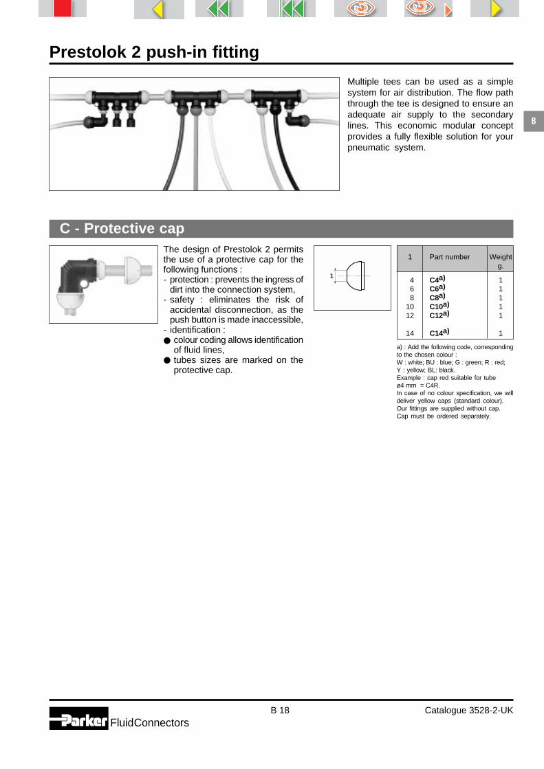
Prestolok 2 push-in fitting
B 18 Catalogue 3528-2-UKFluidConnectors
B
a) : Add the following code, correspondingto the chosen colour :W : white; BU : blue; G : green; R : red;Y : yellow; BL: black.Example : cap red suitable for tubeø4 mm = C4R.In case of no colour specification, we willdeliver yellow caps (standard colour).Our fittings are supplied without cap.Cap must be ordered separately.
C - Protective cap
1 Part number Weightg.
4 C4a) 16 C6a) 18 C8a) 1
10 C10a) 112 C12a) 1
14 C14a) 1
Multiple tees can be used as a simplesystem for air distribution. The flow paththrough the tee is designed to ensure anadequate air supply to the secondarylines. This economic modular conceptprovides a fully flexible solution for yourpneumatic system.
The design of Prestolok 2 permitsthe use of a protective cap for thefollowing functions :- protection : prevents the ingress of
dirt into the connection system,- safety : eliminates the risk of
accidental disconnection, as thepush button is made inaccessible,
- identification :● colour coding allows identification
of fluid lines,● tubes sizes are marked on the
protective cap.
1
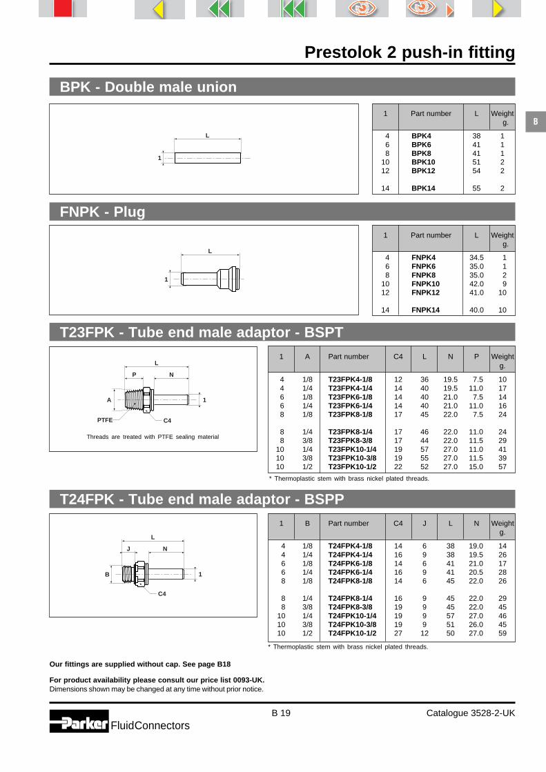
Prestolok 2 push-in fitting
B 19 Catalogue 3528-2-UKFluidConnectors
B
T23FPK - Tube end male adaptor - BSPT
Dimensions shown may be changed at any time without prior notice.
FNPK - Plug
BPK - Double male union
1 Part number L Weightg.
4 BPK4 38 16 BPK6 41 18 BPK8 41 1
10 BPK10 51 212 BPK12 54 2
14 BPK14 55 2
1 A Part number C4 L N P Weightg.
4 1/8 T23FPK4-1/8 12 36 19.5 7.5 104 1/4 T23FPK4-1/4 14 40 19.5 11.0 176 1/8 T23FPK6-1/8 14 40 21.0 7.5 146 1/4 T23FPK6-1/4 14 40 21.0 11.0 168 1/8 T23FPK8-1/8 17 45 22.0 7.5 24
8 1/4 T23FPK8-1/4 17 46 22.0 11.0 248 3/8 T23FPK8-3/8 17 44 22.0 11.5 29
10 1/4 T23FPK10-1/4 19 57 27.0 11.0 4110 3/8 T23FPK10-3/8 19 55 27.0 11.5 3910 1/2 T23FPK10-1/2 22 52 27.0 15.0 57
1 B Part number C4 J L N Weightg.
4 1/8 T24FPK4-1/8 14 6 38 19.0 144 1/4 T24FPK4-1/4 16 9 38 19.5 266 1/8 T24FPK6-1/8 14 6 41 21.0 176 1/4 T24FPK6-1/4 16 9 41 20.5 288 1/8 T24FPK8-1/8 14 6 45 22.0 26
8 1/4 T24FPK8-1/4 16 9 45 22.0 298 3/8 T24FPK8-3/8 19 9 45 22.0 45
10 1/4 T24FPK10-1/4 19 9 57 27.0 4610 3/8 T24FPK10-3/8 19 9 51 26.0 4510 1/2 T24FPK10-1/2 27 12 50 27.0 59
* Thermoplastic stem with brass nickel plated threads.
* Thermoplastic stem with brass nickel plated threads.
Our fittings are supplied without cap. See page B18
For product availability please consult our price list 0093-UK.
1
L
1
L
P N
C4PTFE
A
1
L
J N
C4
B
Threads are treated with PTFE sealing material
T24FPK - Tube end male adaptor - BSPP
1
L
1 Part number L Weightg.
4 FNPK4 34.5 16 FNPK6 35.0 18 FNPK8 35.0 2
10 FNPK10 42.0 912 FNPK12 41.0 10
14 FNPK14 40.0 10

Prestolok 2 push-in fitting
B 20 Catalogue 3528-2-UKFluidConnectors
B
Dimensions shown may be changed at any time without prior notice.
T28FPK - Tube end male adaptor-metric straight thread
1 B Part number C4 J L N Weightg.
4 M5X0.8 T28FPK4M5 12 5 43 19.5 126 M5X0.8 T28FPK6M5 14 5 43 21.0 17
1
L
J N
C4
B* Thermoplastic stem with brass nickel plated threads.
1 2 Part number L Weight g.
4 6 TR2PK6-4 38 44 8 TR2PK8-4 36 66 8 TR2PK8-6 39 44 10 TR2PK10-4 41 166 10 TR2PK10-6 43 3
8 10 TR2PK10-8 47 46 12 TR2PK12-6 36 38 12 TR2PK12-8 38 7
10 12 TR2PK12-10 48 48 14 TR2PK14-8 39 8
10 14 TR2PK14-10 42 512 14 TR2PK14-12 51 14
TR2PK - Tube end reducer
2
L
1
TS2PK - Pressure indicator
1
L 1 Part number L Weightg.
4 TS2PK4 36 56 TS2PK6 37 68 TS2PK8 36 8
For product availability please consult our price list 0093-UK.

Prestolok 2 push-in fitting
B 21 Catalogue 3528-2-UKFluidConnectors
B
Cartridges
Prestolok cartridge fittingsPrestolok compact drive-in cartridgefittings for plastic tubes, are designedfor use in pneumatic components forlow-pressure applications.They eliminate the need for threadedports in system components, andallow the construction of space-saving assemblies.Simple stepped holes are sufficient toreceive these cartridges, which areavailable in tube outer diameters from4 mm to 12 mm.Prestolok compact drive-in cartridgescan be fitted into pneumatic compo-nents made of non-ferrous metals(brass, aluminium, zinc-aluminiumalloy), and most industrial plastics.They are particularly suitable forthe mass production of pneumaticcomponents. For more informationon potential applications, pleaseconsult your Parker sales engineer.
Stepped hole for cartridge reception
Depending upon the componentmaterial used, the stepped holesfor the reception of the drive-incartridges are obtained by drillingor injection moulding. Dimensionsand tolerances are defined by theconfiguration of the cartridge.For this purpose, we supply step-ped drilling tools corresponding toeach cartridge type.Technical information available onrequest.

Prestolok 2 push-in fitting
B 22 Catalogue 3528-2-UKFluidConnectors
B
Dimensions shown may be changed at any time without prior notice.
Cartridges
1 - Position the mandrel above the port.2 - Insert cartridge with drive-in tool.3 - Remove mandrel from fitted cartridge.4 - Insert push sleeve into cartridge.5 - Final cartridge and tube assembly.
PackagingPrestolok drive-in cartridges are supplied in packs of 200 or 250 units (depending on the part number) stored instacked thermoplastic packing trays. This prevents damage during shipment and simplifies stock control and producthandling.
Cartridge assemblyPrestolok compact drive-in cartridges are installed using a simple tool (one tool for each cartridge size).
2 3 4
5
1

Prestolok micro
Catalogue 3528-3-UK

Prestolok micro
C 2 Catalogue 3528-3-UKFluidConnectors
C
Index
Straightconnectors
90° elbows
Tees
adjustable male run adjustable male adjustable male adjustable malemetric branch - BSPT branch - BSPP branch - metricR68PMK - p. C 12 S63PMK - p. C 12 S64PMK - p. C 13 S68PMK - p. C 13
equal union adjustable male run adjustable male runequal union with mounting holes BSPT BSPPJPMK - p. C 11 JPMFK - p. C 11 R63PMK - p. C 12 R64PMK - p. C 12
adjustable equal unionmale metric equal union with mounting hole compact plug-inC68PMK - p. C 10 EPMK - p. C 10 EPMFK - p. C 11 T2ESPMK - p. C 11
adjustable extended adjustable adjustable extended adjustable adjustable extendedmale - BSPT male - BSPT male - BSPP male - BSPP male - metricC63LPMK - p. C 9 C63PMK - p. C 9 C64LPMK - p. C 9 C64PMK - p. C 10 C68LPMK - p. C 10
female - BSPP female - metric equal union unequal union equal bulkheadG4PMB - p. C 8 G8PMB - p. C 8 HPMK - p. C 8 HPMK - p. C 8 WPMB - p. C 9
male - BSPT male - metricinternal hexagon internal hexagon male - BSPT male - BSPP male - metricF23PMB - p. C 7 F28PMB - p. C 7 F3PMB - p. C 7 F4PMB - p. C 7 F8PMB - p. C 8

Prestolok micro
C 3 Catalogue 3528-3-UKFluidConnectors
C
Index
Y connectors
Banjos
Adaptors /Accessories
plug tube end expander tube end reducerFNPMK - p. C 15 TE2PMK - p. C 15 TR2PMK - p. C 16
single assembledCOR8PMB - p. C 15
tube end male adaptor tube end male adaptor tube end male adaptorBSPT BSPP metricT23FPMB - p. C 16 T24FPMB - p. C 16 T28FPMB - p. C 16
Technical tubing Please consult Thermoplastic single tubes and Pneumo-Tube bundles section (P).
adjustable male adjustable maleunequal - plug-in BSPT metricYJ2PMK - p. C 14 YJ63PMK - p. C 14 YJ68PMK - p. C 15
equal unionequal union unequal union with mounting holes equal - plug-inYJPMK - p. C 13 YJPMK - p. C 13 YJPMFK - p. C 14 YJ2PMK - p. C 14

Prestolok micro
C 4 Catalogue 3528-3-UKFluidConnectors
C
2
1
6 4 3
5
Technical features
Applications
Prestolok micro is designed to reducespace, save weight and time duringassembly and bring a cost effectivesolution for all applications. Prestolokmicro can be a real economy.
Prestolok micro's unique charac-teristics make it the perfect connectorfor miniature pneumatic systems in awide range of applications.
Developed for use with pneumaticsystems in a wide variety of indus-tries, Prestolok micro is designed toconvey many other fluids (pleaseconsult us) thus covering a broadrange of applications.
Principle
To provide the fitting solution for miniature pneumaticapplications Parker has introduced a new range of instantfittings, Prestolok micro.This complementary product range has been specificallydeveloped to provide the perfect connection for smalldiameter tubing used in many industries and applications.This new fitting benefits from the constant improvements thatParker has brought to the instant fitting market.Prestolok micro uses "elastic teeth" stainless steel grab ringtechnology.This system invented by Parker and developed throughprevious generations of Prestolok fittings provides perfecttube retention without damaging the tube, thus guaranteeing aleak free connection.Prestolok micro is designed for use with Parker calibratedpolyamide and polyurethane tubing (see Thermoplasticsingle tube and Pneumo-Tube bundles section - P*).
* For other materials, please consult us.
Prestolok micro : push-in fitting for miniature pneumatic applications
Packaging
Machine tools
Precision machinery
Food industry
Textile Robotics
Automotive
Ink marking
Working Workingpressure temperature
From 0.01to
16 bar
From - 25° Cto
+ 80° C
Material
1 2 3 4 5 6
Body Threaded parts Sleeve Grab ring Push O-Ringbutton
Polyamide Nickel plated Brass (Npb for Stainless Polyacetal NitrileHR brass straight connect.) steel

Prestolok micro
C 5 Catalogue 3528-3-UKFluidConnectors
C
Advantages
Perfect miniaturisation.The Prestolok micro concept offers :
● an ergonomic shape with smalldimensions but allowing forexcellent handling and manipulationof the fitting,
● compact dimensions allow efficientutilisation in applications wherespace is a decisive factor,
● reduced size and weight which,are very important when used withunsupported pipe runs,
● excellent flow characteristics giveminimal pressure drop.
A multi-functional push-button.● the new push button design
encapsulates the fitting body toprevent contamination,
● the profile of the push buttonenables simple and efficientdisconnection of the tube,
● the marking of the tube diameter andthe optional choice of colour on thepush button enable simple identifica-tion of circuits,
● it ensures a uniform distributionof the pushing force for easydisconnection.
● the one piece design makes thepush button unlosable.
Ready-to-use fitting● the Prestolok micro range of fittings
is manufactured ready to use,saving time and reducing assemblycosts :
● taper threads are treated witha special PTFE. This factory appliedtreatment enables the fitting to beconnected and disconnected up tofive times without additionaltreatment,
● fittings with parallel threads aresupplied with a pre-assembled fullyretained O-ring ensuring a perfectseal.
■ Wide product range suitable for many applications. ■ Nickel plated brass adaptors.■ Full flow capacity.
Positive retention with a flexiblegrab ring.● this system, invented, developed
and perfected by Parker, guaranteesexcellent tube retention,
● the special radial shape of theteeth of the grab ring do not damagethe tube or affect the sealing,
● the elasticity of the grab ring absorbsall vibration and impulsing,
● the design of the grab ring allowsthe tube to rotate freely even underpressure.
High resistance polyamide body.The use of high resistance polyamideoffers :● excellent mechanical characte-
ristics (robustness),● high corrosion resistance,● UV resistant polymers guarantee a
long service life.
Mounting holes on shaped fittings.On request, union connectors can besupplied equipped with mountingholes. This option permits :● mounting in banks for compact
installations and simplified pipe-work,
● facility for mounting on frames orpanels,
● greater flexibility and additionalspace saving.

Prestolok micro
C 6 Catalogue 3528-3-UKFluidConnectors
C
Instructions for use
Cut the tube square For threaded fittings, tighten to therecommended assembly torque.
Assembly :Prestolok micro must only be used with calibrated polyamide (in accordance with DIN 73378, BS 5409 Part 2,NF E49-100, CETOP RP45B) and polyurethane (in accordance with NF E49-101) tubing conforming to standardsshown in Thermoplastic single tubes and Pneumo-Tube bundles section (P). For other tubing materials pleaseconsult us.
Insert the tube into the fitting until itbottoms.
Disassembly :Simply press on the push button and withdraw the tube.
F23PMB and F28PMB straight maleconnectors have an internal hexagonfor use with an Allen key to allow thefitting to be mounted in any position.This also permits close porting notpossible when a spanner is used.
Assembly torque
Thread M3 M5 G1/8’’ G1/4’’
max.Torque 0.1 0.2 1.0 2.0m. da N

Prestolok micro
C 7 Catalogue 3528-3-UKFluidConnectors
C
Dimensions shown may be changed at any time without prior notice.
F23PMB - Male connector - BSPTWeight
g.
F28PMB - Male connector - metric straight thread
F3PMB - Male connector - BSPT
Weightg.
1 B Part number C E J N
4 1/8 F4PMB4-1/8 13 7.9 5.0 7.9 84 1/4 F4PMB4-1/4 16 7.9 5.5 7.9 126 1/8 F4PMB6-1/8 13 10.5 5.0 12.3 106 1/4 F4PMB6-1/4 16 10.5 5.5 8.8 14
Weightg.
1 A Part number C P R
4 1/8 F3PMB4-1/8 10 6.5 11.4 74 1/4 F3PMB4-1/4 14 10.0 13.4 116 1/8 F3PMB6-1/8 11 6.5 14.8 106 1/4 F3PMB6-1/4 14 10.0 13.8 16
Weightg.
This fitting has been designed for use where space is at a premium.It is assembled using the internal hexagon and an Allen key.
This fitting has been designed for use where space is at a premium.It is assembled using the internal hexagon and an Allen key.
F4PMB - Male connector - BSPP
For product availability please consult our price list 0093-UK.
1
R internalhex
P
AE
PTFE
1
N J
BE
E
R
P
A
C
PTFE
1
N J
BE
C
1 A Part number E P R Int. H
3 1/8 F23PMB3-1/8 6.5 6.5 10.2 2.0 44 1/8 F23PMB4-1/8 7.9 6.5 11.4 2.5 56 1/8 F23PMB6-1/8 10.5 6.5 14.1 3.0 7
Threads are treated with PTFE sealing material.
Threads are treated with PTFE sealing material.
1 B Part number E J N Int. H
3 M3x0.5 F28PMB3M3 7.0 3.25 13.65 1.5 53 M5x0.8 F28PMB3M5 6.5 3.50 9.80 2.0 54 M3x0.5 F28PMB4M3 7.9 3.25 14.15 1.5 64 M5x0.8 F28PMB4M5 7.9 3.50 11.70 2.0 66 M5x0.8 F28PMB6M5 10.5 3.50 14.80 2.0 7

Prestolok micro
C 8 Catalogue 3528-3-UKFluidConnectors
C
Dimensions shown may be changed at any time without prior notice.
F8PMB - Male - metric straight threadWeight
g.
G4PMB - Female - BSPPWeight
g.
G8PMB - Female - metric
1 B Part number C E J L
3 M3x0.5 G8PMB3M3 7 6.5 4.25 14.05 53 M5x0.8 G8PMB3M5 7 6.5 6.60 17.90 54 M3x0.5 G8PMB4M3 8 7.9 4.25 14.55 54 M5x0.8 G8PMB4M5 8 7.9 6.60 18.40 5
Weightg.
HPMK - Equal unionWeight
g.
HPMK - Unequal unionWeight
g.
For product availability please consult our price list 0093-UK.
1
N J
BE
C
1 BE
LJ
C
1 BE
LJ
C
1E
L
2
1E
L
2
1 B Part number C E J N
3 M3x0.5 F8PMB3M3 7 6.5 3.25 11.45 53 M5x0.8 F8PMB3M5 7 6.5 3.50 11.20 54 M3x0.5 F8PMB4M3 8 7.9 3.25 11.95 54 M5x0.8 F8PMB4M5 8 7.9 3.50 11.80 76 M5x0.8 F8PMB6M5 11 10.5 3.50 14.80 7
1 B Part number C E J L
4 1/8 G4PMB4-1/8 13 7.9 8 19.9 94 1/4 G4PMB4-1/4 16 7.9 10 21.9 156 1/8 G4PMB6-1/8 13 10.5 8 22.8 106 1/4 G4PMB6-1/4 16 10.5 10 24.8 15
1 2 Part number E L
3 3 HPMK3 7.3 19.8 24 4 HPMK4 8.5 21.8 36 6 HPMK6 11.5 27.8 3
1 2 Part number E L
4 3 HPMK4-3 8.5 21.2 26 4 HPMK6-4 11.5 27.8 3

Prestolok micro
C 9 Catalogue 3528-3-UKFluidConnectors
C
Dimensions shown may be changed at any time without prior notice.
WPMB - Bulkhead equal union
C63LPMK - Adjustable extended male elbow - BSPT
C63PMK - Adjustable male elbow - BSPT
C64LPMK - Adjustable extended male elbow - BSPPWeight
g.
Weightg.
Wmaxi.
Weightg.
Weightg.
For product availability please consult our price list 0093-UK.
1
R
E
M
C
P
A PTFE
1
R
E
M
C
P
A PTFE
1
N
E
M
C
J
B
1 1
L
W
BC C
Threads are treated with PTFE sealing material.
Threads are treated with PTFE sealing material.
1 B Part number C E J M N
4 1/8 C64LPMK4-1/8 13 8.5 5.0 12.65 17.2 104 1/4 C64LPMK4-1/4 16 8.5 5.5 12.65 17.2 136 1/8 C64LPMK6-1/8 13 11.5 5.0 16.70 23.7 126 1/4 C64LPMK6-1/4 16 11.5 5.5 16.70 21.7 12
1 B Part number C L
3 M8x1 WPMB3 12 20.15 5 104 M10x1 WPMB4 14 21.15 5 116 M12x1 WPMB6 16 26.00 8 13
1 A Part number C E M P R
3 1/8 C63PMK3-1/8 10 7.3 11.25 6.5 11.6 64 1/8 C63PMK4-1/8 10 8.5 12.65 6.5 12.2 64 1/4 C63PMK4-1/4 14 8.5 12.65 10.0 14.2 66 1/8 C63PMK6-1/8 11 11.5 16.70 6.5 13.7 76 1/4 C63PMK6-1/4 14 11.5 16.70 10.0 15.7 7
1 A Part number C E M P R
3 1/8 C63LPMK3-1/8 10 7.3 11.25 6.5 19.4 124 1/8 C63LPMK4-1/8 10 8.5 12.65 6.5 21.2 144 1/4 C63LPMK4-1/4 14 8.5 12.65 10.0 23.2 276 1/8 C63LPMK6-1/8 11 11.5 16.70 6.5 25.7 196 1/4 C63LPMK6-1/4 14 11.5 16.70 10.0 27.7 35

Prestolok micro
C 10 Catalogue 3528-3-UKFluidConnectors
C
Dimensions shown may be changed at any time without prior notice.
C64PMK - Adjustable male elbow - BSPP
C68LPMK - Adjustable extended male elbow - metric straight
C68PMK - Adjustable male elbow - metric straight thread
EPMK - Equal elbow
Weightg.
Weightg.
Weightg.
Weightg.
For product availability please consult our price list 0093-UK.
1
N
E
M
C
J
B
1
N
E
M
CJ
B
1N
E
M
C J
B
1
M
M
E
1 B Part number C E J M N
4 1/8 C64PMK4-1/8 13 8.5 5.0 12.65 5 64 1/4 C64PMK4-1/4 16 8.5 5.5 12.65 5 66 1/8 C64PMK6-1/8 13 11.5 5.0 16.70 9 76 1/4 C64PMK6-1/4 16 11.5 5.5 16.70 9 7
1 B Part number C E J M N
3 M3x0.5 C68LPMK3M3 6 7.3 3.25 11.25 17.0 73 M5x0.8 C68LPMK3M5 8 7.3 3.50 11.25 17.0 84 M3x0.5 C68LPMK4M3 8 8.5 3.25 12.65 18.8 84 M5x0.8 C68LPMK4M5 8 8.5 3.50 12.65 18.8 86 M5x0.8 C68LPMK6M5 10 11.5 3.50 16.70 23.7 9
1 B Part number C E J M N
3 M3x0.5 C68PMK3M3 7 7.3 3.25 11.25 9.2 63 M5x0.8 C68PMK3M5 7 7.3 3.50 11.25 9.2 64 M3x0.5 C68PMK4M3 8 8.5 3.25 12.65 9.8 64 M5x0.8 C68PMK4M5 8 8.5 3.50 12.65 9.8 66 M5x0.8 C68PMK6M5 11 11.5 3.50 16.70 11.7 7
1 Part number E M
3 EPMK3 7.3 11.25 24 EPMK4 8.5 12.65 36 EPMK6 11.5 16.70 3

Prestolok micro
C 11 Catalogue 3528-3-UKFluidConnectors
C
Dimensions shown may be changed at any time without prior notice.
EPMFK - Equal elbow with mounting hole
T2ESPMK - Compact plug-in elbow
JPMK - Equal tee
JPMFK - Equal tee with mounting holes
Weightg.
Weightg.
Weightg.
Weightg.
Not available from stock, please consult us.
Not available from stock, please consult us.
For product availability please consult our price list 0093-UK.
1
H
E
M
2
1S
M
SM
SM
L
Ø3xQ
E
1S
M
SM
Ø3xQ
E
1
M
M M
L
E
1 Part number E M Ø 3 Q S
3 EPMFK3 7.3 11.25 3.2 7.3 5.0 24 EPMFK4 8.5 12.65 3.2 8.5 5.5 36 EPMFK6 11.5 16.70 3.2 11.5 7.0 4
1 2 Part number E H M
3 3 T2ESPMK3 7.3 16 11.25 23 4 T2ESPMK3-4 7.3 16 11.25 24 4 T2ESPMK4 8.5 16 12.65 24 6 T2ESPMK4-6 8.5 17 12.65 26 6 T2ESPMK6 11.5 17 16.70 3
1 Part number E L M Ø 3 Q S
3 JPMFK3 7.3 22.5 11.25 3.2 7.3 5.0 34 JPMFK4 8.5 25.3 12.65 3.2 8.5 5.5 46 JPMFK6 11.5 33.4 16.70 3.2 11.5 7.0 5
1 Part number E L M
3 JPMK3 7.3 22.5 11.25 34 JPMK4 8.5 25.3 12.65 36 JPMK6 11.5 33.4 16.70 4

Prestolok micro
C 12 Catalogue 3528-3-UKFluidConnectors
C
Dimensions shown may be changed at any time without prior notice.
R63PMK - Adjustable male run tee - BSPT
R64PMK - Adjustable male run tee - BSPP
R68PMK - Adjustable male run tee - metric straight thread
S63PMK - Adjustable male branch tee - BSPT
Weightg.
Weightg.
Weightg.
Weightg.
For product availability please consult our price list 0093-UK.
1 B
M
M N J
E
C
1 B
M
M N J
E
C
1
R
E
M M
CP
A PTFE
1
M
M R
E
P
A
C
PTFE
Threads are treated with PTFE sealing material.
Threads are treated with PTFE sealing material.
1 A Part number C E M P R
3 1/8 R63PMK3-1/8 10 7.3 11.25 6.5 11.6 74 1/8 R63PMK4-1/8 10 8.5 12.65 6.5 12.2 74 1/4 R63PMK4-1/4 14 8.5 12.65 10.0 14.2 76 1/8 R63PMK6-1/8 11 11.5 16.70 6.5 13.7 86 1/4 R63PMK6-1/4 14 11.5 16.70 10.0 15.7 8
1 B Part number C E J M N
4 1/8 R64PMK4-1/8 13 8.5 5.0 12.65 8.2 74 1/4 R64PMK4-1/4 16 8.5 5.5 12.65 8.2 76 1/8 R64PMK6-1/8 13 11.5 5.0 16.70 11.7 86 1/4 R64PMK6-1/4 16 11.5 5.5 16.70 9.7 9
1 B Part number C E J M N
3 M3x0.5 R68PMK3M3 7 7.3 3.25 11.25 9.2 63 M5x0.8 R68PMK3M5 7 7.3 3.50 11.25 9.2 64 M3x0.5 R68PMK4M3 8 8.5 3.25 12.65 9.8 74 M5x0.8 R68PMK4M5 8 8.5 3.50 12.65 9.8 76 M5x0.8 R68PMK6M5 11 11.5 3.50 16.70 11.7 8
1 A Part number C E M P R
3 1/8 S63PMK3-1/8 10 7.3 11.25 6.5 11.6 74 1/8 S63PMK4-1/8 10 8.5 12.65 6.5 12.2 74 1/4 S63PMK4-1/4 14 8.5 12.65 10.0 14.2 76 1/8 S63PMK6-1/8 11 11.5 16.70 6.5 13.7 86 1/4 S63PMK6-1/4 14 11.5 16.70 10.0 15.7 8

Prestolok micro
C 13 Catalogue 3528-3-UKFluidConnectors
C
Dimensions shown may be changed at any time without prior notice.
S64PMK - Adjustable male branch tee - BSPP
S68PMK - Adjustable male branch tee - metric straight thread
YJPMK - Equal Y union
YJPMK - Unequal Y union
Weightg.
Weightg.
Weightg.
Weightg.
For product availability please consult our price list 0093-UK.
1
N
J
E���
M M
B
C
1
N
J
E
M M
B
C
1
1
L2L1
L
2
1
1
L2L1
L
2
1 2 Part number L L1 L2
3 3 YJPMK3 22.0 13.9 6.7 34 4 YJPMK4 24.8 16.4 8.1 46 6 YJPMK6 31.8 22.2 10.8 5
1 2 Part number L L1 L2
3 4 YJPMK4-3 24.2 16.4 8.1 33 6 YJPMK6-3 31.2 22.2 10.8 44 6 YJPMK6-4 31.8 22.2 10.8 4
1 B Part number C E J M N
3 M3x0.5 S68PMK3M3 7 7.3 3.25 11.25 9.2 63 M5x0.8 S68PMK3M5 7 7.3 3.50 11.25 9.2 64 M3x0.5 S68PMK4M3 8 8.5 3.25 12.65 9.8 74 M5x0.8 S68PMK4M5 8 8.5 3.50 12.65 9.8 76 M5x0.8 S68PMK6M5 11 11.5 3.50 16.70 11.7 8
1 B Part number C E J M N
4 1/8 S64PMK4-1/8 13 8.5 5.0 12.65 8.2 74 1/4 S64PMK4-1/4 16 8.5 5.5 12.65 8.2 76 1/8 S64PMK6-1/8 13 11.5 5.0 16.70 11.7 86 1/4 S64PMK6-1/4 16 11.5 5.5 16.70 9.7 9

Prestolok micro
C 14 Catalogue 3528-3-UKFluidConnectors
C
Dimensions shown may be changed at any time without prior notice.
YJPMFK - Y union with mounting holes
YJ2PMK - Equal plug-in Y union
YJ63PMK - Adjustable male Y connector - BSPT
YJ2PMK - Unequal plug-in Y union
Weightg.1 Part number L L1 L2 Ø 3 Q S T
3 YJPMFK3 22.0 13.9 6.7 3.2 7.3 5.0 8.7 34 YJPMFK4 24.8 16.4 8.1 3.2 8.5 5.5 9.7 46 YJPMFK6 31.8 22.2 10.8 3.2 11.5 7.0 12.9 5
Not available from stock, please consult us.
Weightg.
Weightg.
Weightg.
For product availability please consult our price list 0093-UK.
1
1
L2L1
LT
1S
S
Ø3xQ
1
1
L2 2L1
H
L
1
1
L2L1
R
P
A
C
PTFE
1
1
L2 2L1
H
L
Threads are treated with PTFE sealing material.
1 A Part number C L1 L2 P R
3 1/8 YJ63PMK3-1/8 10 14.0 6.7 6.5 27.2 74 1/8 YJ63PMK4-1/8 10 16.6 8.1 6.5 29.4 76 1/8 YJ63PMK6-1/8 11 22.3 10.8 6.5 36.4 9
1 2 Part number H L L1 L2
4 3 YJ2PMK4-3 16 37.9 16.4 8.1 36 4 YJ2PMK6-4 16 44.9 22.2 10.8 4
1 2 Part number H L L1 L2
3 3 YJ2PMK3 16 35.7 13.9 6.7 34 4 YJ2PMK4 16 37.9 16.4 8.1 36 6 YJ2PMK6 17 45.9 22.2 10.8 3

Prestolok micro
C 15 Catalogue 3528-3-UKFluidConnectors
C
Dimensions shown may be changed at any time without prior notice.
FNPMK - Plug
YJ68PMK - Adjustable male Y connector - metric straight thread
COR8PMB - Banjo - metric straight threadWeight
g.
TE2PMK - Tube end expanderWeight
g.
Weightg.
Weightg.
For product availability please consult our price list 0093-UK.
1T
N
KE
MC4
J
B
1
1
L2L1
N J
B
C
1
L
12
L
1 B Part number C J L1 L2 N
3 M3x0.5 YJ68PMK3M3 8 3.25 14.0 6.7 24.2 74 M5x0.8 YJ68PMK4M5 9 3.50 16.6 8.1 26.2 76 M5x0.8 YJ68PMK6M5 12 3.50 22.3 10.8 34.1 8
1 B Part number C4 E J K M N T
3 M3x0.5 COR8PMB3M3 6 6.5 3.25 0.5 12.5 10 4 53 M5x0.8 COR8PMB3M5 8 6.5 4.50 0.5 13.5 10 4 5
1 Part number L
3 FNPMK3 22 1
1 2 Part number L
6 4 TE2PMK4-6 31.7 2

Prestolok micro
C 16 Catalogue 3528-3-UKFluidConnectors
C
Dimensions shown may be changed at any time without prior notice.
TR2PMK - Tube end reducer
T24FPMB - Tube end male adaptor - BSPP
T28FPMB - Tube end male adaptor - metric
1 B Part number C H J O
3 M3x0.5 T28FPMB3M3 6 16 3.25 19 64 M5x0.8 T28FPMB4M5 7 16 3.50 19 7
Weightg.
T23FPMB - Tube end male adaptor - BSPTWeight
g.
Weightg.
Weightg.
For product availability please consult our price list 0093-UK.
1
RH
P
A
C
PTFE
1 B
O
H
JC
1 2 Part number L
3 4 TR2PMK4-3 26.4 2
1 A Part number C H P R
4 1/8 T23FPMB4-1/8 10 16 6.5 22.5 94 1/4 T23FPMB4-1/4 14 16 10.0 25.0 136 1/8 T23FPMB6-1/8 10 17 6.5 23.5 96 1/4 T23FPMB6-1/4 14 17 10.0 26.0 15
1 B Part number C H J O
4 1/8 T24FPMB4-1/8 13 16 5.0 19.5 94 1/4 T24FPMB4-1/4 16 16 5.5 19.5 136 1/8 T24FPMB6-1/8 13 17 5.0 20.5 96 1/4 T24FPMB6-1/4 16 17 5.5 20.5 131 B
O
H
JC
Threads are treated with PTFE sealing material.
2
L
1

Catalogue 3528-1-UK
PrestolokPush-in fitting for fluids

Prestolok push-in fitting
D 2 Catalogue 3528-1-UKFluidConnectors
D
Index
male - BSPTF23PB - p. D 6
male - BSPTF3PB - p. D 6
Straightconnectors
Bulkheadunions
90° elbows
adjustable extendedmale - BSPTC63LPB - p. D 9
Tees
adjustable male branch -metricS68PB - p. D 13
compact - BSPTC3PB - p. D 9
male - metricF28PB - p. D 6
adjustable male run- metricR68PB - p. D 13
equal unionJPB - p. D 12
adjustable malerun - BSPTR63PB - p. D 12
adjustable malerun - BSPPR64PB - p. D 12
adjustable malebranch - BSPTS63PB - p. D 13
equal unionEPB - p. D 11
adjustable bulkheadunion WE6PB - p. D 11
compact adjustablemale - BSPPC64SPB - p. D 10
adjustable male- metricC68PB - p. D 11
compact adjustablemale - metricC68SPB - p. D 11
adjustable maleNPTFC6PB - p. D 9
male - NPTFFPB - p. D 6
adjustable maleBSPTC63PB - p. D 10
adjustable maleBSPPC64PB - p. D 10
equal unionHPB - p. D 8
female - BSPPWG4PB - p. D 8
L
W
J B 2
C 1C 2
1B 1
equalWPB - p. D 9
male - BSPPF4PB - p. D 7
male - metricF8PB - p. D 7
female - BSPPG4PB - p. D 8
adjustable malebranch - BSPPS64PB - p. D 13
mixedWBMPB - p. D 8

Prestolok push-in fitting
D 3 Catalogue 3528-1-UKFluidConnectors
D
IndexBanjos
single - body onlyCORPB - p. D 14
double - body onlyCORPBD - p. D 14
single - assembledCOR8PB/COR4PB - p. D 14
double - assembledCOR8PBD/COR4PBD - p. D 15
single boltwith sealsSC8U/SC4U - p. D 15
stacking boltwith sealsSC8UD/SC4UD - p. D 15
Adaptors/Accessories
plugFNPB - p. D 16
tube end expanderTEPB - p. D 16
tube end reducerTRPB - p. D 16
tube end male adaptorBSPTT23HFPB - p. D 16
Technical tubing Please consult Thermoplastic single tubes and Pneumo-Tube bundles section (P)
Complementary Please consult Prestolok 2 section (B)parts withthermoplasticbody

Prestolok push-in fitting
D 4 Catalogue 3528-1-UKFluidConnectors
D
For more than 20 years, Parker Han-nifin has designed and manufacturedpush-in fittings recognised worldwidefor their quality and reliability.During this period Prestolok hasbenefited from continuous impro-vement and is now one of the mostadvanced push-in fittings on themarket.Prestolok uses "elastic teeth" grabring technology invented and per-fected by Parker, who guarantee itsexcellent tube retention qualities.Prestolok can be used not only withmost types of plastic tubing availableon the market (see Thermoplasticsingle tube and Pneumo-Tubebundles section P), but also withsome metal tubing*, making it suitablefor a wide range of applications.
* See advantages section
Principle
Technical features
Applications
Nickel platedbrass
From - 25° Cto
+ 100° CNitrile
Back-upwasher
Pushbutton
Stainlesssteel
Brass
Body
Nickel platedbrass
Threaded parts Sleeve
Polyacetal Brass
From 0.01to
25 bar
Grab ring
Prestolok has been designed tohandle many industrial fluidscompatible with its technicalfeatures.
Thanks to its mechanical properties,Prestolok is a push-in fittingparticularly suited to the mostsevere environments, such asweld ing, h igh temperatures,v ibrat ion.
7 6 3 5
1
2
Workingpressure
Workingtemperature
Material
Climate control Automotive
Food industry
Machine tools
Welding
Prestolok : push-in fitting for fluid and arduous pneumatic applications
Packaging
4
1 2 3 4 5 6 7
O-ring

Prestolok push-in fitting
D 5 Catalogue 3528-1-UKFluidConnectors
D
Advantages
Compact ready-to-use fittingWide product range covering all applicationsFull flow capability
Brass nickel plated bodyBrass is a raw material providing :- robustness,- excellent shock resistance,- good temperature capability,- excellent spark resistance.Nickel plating gives improved corro-sion resistance and a bright appea-rance which does not deteriorate.
Use with plastic or metal tubingPrestolok is a high performance push-in fitting.Designed for use with most types ofplastic tubing (polyamide, polyurethane,polyethylene, Pebax, Teflon®...), thishigh performance fitting can also beused with copper tubing* conformingto DIN 1786, NFA51-120, BS 2871Part 2 (tolerance +0.05 mm). Forsteel, stainless steel tubing or otherraw materials, please contact yourParker sales engineer.* Tube must be cut square and correctly deburred.
Positive hold by a flexible stainlesssteel grab ring- the special shape of the radial teeth
of the grab ring prevents longditudinalscratch marks on the tube.
- the elasticity of the grab ring absorbsvibration and pulsating pressure.
- a twist-free assembly, the tube canrotate freely even under pressure.
Ready-to-use fittingThe Prestolok range is manufacturedwith brass nickel plated male threadsready for use :- parallel threads are supplied with a
preassembled, fully retained O-Ringseal,
- taper threads are treated witha special PTFE for self sealing onassembly,reusable up to five timeswithout additional sealing material.
Plastic push button- simple manual pressure on the
user-friendly push button allowsinstant disconnection of the tube.
- tube sizes are marked on the pushbutton for easy identification.
How to use
Straight male connectors withinternal hexagon- the internal hexagon allows vertical
mounting with the use of an Allenkey. Because the internal hexagondoes not go completely through thefitting, the fittingcannot slip downthe Allen key during assembly.
- the lack of external hexagon gives asignificant reduction in the overalldimensions enabling close mountingof these fittings to give very compactinstallations.
Assembly- Cut the tube square (and correctly deburred for copper)- Insert the tube into the fitting until it bottoms.
Disassembly- Simply press on the push button and withdraw the
tube.

Prestolok push-in fitting
D 6 Catalogue 3528-1-UKFluidConnectors
D
For product availability please consult our price list 0093-UK.Dimensions shown may be changed at any time without prior notice.
F23PB - Male connector - BSPT
FPB - Male connector - NPTF
1 A Part number L O P H. WeightInt. g.
4 1/8 F23PB4-1/8 21 10 6.5 3 76 1/8 F23PB6-1/8 24 12 6.5 4 106 1/4 F23PB6-1/4 28 14 9.7 4 228 1/8 F23PB8-1/8 28 14 6.5 6 198 1/4 F23PB8-1/4 28 14 9.7 6 25
L
0 A
P
1
PTFE
This fitting has been designed for use where space is at a premium. It is assembled using the internalhexagon and an Allen key.
Threads are treated with PTFE sealing material
1 A Part number C4 L P H. WeightInt. g.
6 1/8-27 FPB6-1/8 14 26.0 10.1 4 156 1/4-18 FPB6-1/4 14 28.5 14.6 4 20
10 1/4-18 FPB10-1/4 19 40.0 14.6 8 4510 3/8-18 FPB10-3/8 19 34.0 14.6 8 4012 3/8-18 FPB12-3/8 22 36.5 14.6 10 45
L
B0
J
1
F28PB - Male connector - metric straight thread
This fitting has been designed for use where space is at a premium. It is assembled using the internalhexagon and an Allen key.
1 B Part number J L O H. WeightInt. g.
4 M3x0.5 F28PB4M3 3.25 24 9.5 2.5 74 M5x0.8 F28PB4M5 5.00 26 9.5 2.5 76 M5x0.8 F28PB6M5 5.00 26 11.5 2.5 9
L
C4
1 A
P
PTFE
F3PB - Male connector - BSPT
Threads are treated with PTFE sealing material
1 A Part number C4 L P H. WeightInt. g.
4 1/8 F3PB4-1/8 12 20.5 17.5 3 144 1/4 F3PB4-1/4 14 23.0 11.0 3 215 1/8 F3PB5-1/8 11 22.5 17.5 4 135 1/4 F3PB5-1/4 14 24.0 11.0 4 176 1/8 F3PB6-1/8 14 24.0 17.5 4 19
6 1/4 F3PB6-1/4 14 24.0 11.0 4 228 1/8 F3PB8-1/8 17 28.0 17.5 4 318 1/4 F3PB8-1/4 17 28.5 11.0 4 318 3/8 F3PB8-3/8 17 26.5 11.5 6 28
10 1/4 F3PB10-1/4 19 35.5 11.0 6 45
10 3/8 F3PB10-3/8 19 33.0 11.5 8 4810 1/2 F3PB10-1/2 22 31.0 15.0 8 4712 1/4 F3PB12-1/4 22 36.5 11.0 6 6812 3/8 F3PB12-3/8 22 36.0 11.5 10 4812 1/2 F3PB12-1/2 22 36.0 15.0 10 56
14 3/8 F3PB14-3/8 24 39.0 11.5 10 9114 1/2 F3PB14-1/2 24 37.0 15.0 11 83
Threads are treated with PTFE sealing material
L
1
P
C4
A
PTFE

Prestolok push-in fitting
D 7 Catalogue 3528-1-UKFluidConnectors
D
F4PB - Male connector - BSPP
All straight male connectors have an internal hexagon(Int.H.) for use with an Allen key to allow the fitting to bemounted in any position. This also permits close porting notpossible when a spanner is used.
1 B Part number C4 J L H WeightInt. g.
4 1/8 F4PB4-1/8 13 6 21.7 3 164 1/4 F4PB4-1/4 16 9 23.3 3 276 1/8 F4PB6-1/8* 13 6 25.3 4 176 1/4 F4PB6-1/4 16 9 26.0 4 418 1/8 F4PB8-1/8* 14 6 27.4 4 24
8 1/4 F4PB8-1/4 16 9 27.4 6 298 3/8 F4PB8-3/8 20 9 28.0 6 59
10 1/4 F4PB10-1/4 17 9 35.4 6 5010 3/8 F4PB10-3/8 20 9 31.4 8 3910 1/2 F4PB10-1/2 24 12 30.3 8 60
12 1/4 F4PB12-1/4 20 9 36.0 6 4912 3/8 F4PB12-3/8* 20 9 35.7 8 4912 1/2 F4PB12-1/2 24 12 34.1 10 7214 3/8 F4PB14-3/8 22 9 38.3 8 6614 1/2 F4PB14-1/2 24 12 37.4 10 81
* No protective cap facility.
F8PB - Male connector - metric straight thread
1
L
JC 4
B
1 B Part number C4 J L H. WeightInt. g.
4 M5x0.8 F8PB4M5 12 5 25.5 2.5 164 M10x1 F8PB4M10 14 8 24.0 3.0 176 M5x0.8 F8PB6M5 14 5 26.0 2.5 176 M10x1 F8PB6M10 14 8 28.0 4.0 176 M12x1.5 F8PB6M12 17 10 30.0 4.0 23
8 M12x1.5 F8PB8M12 17 10 30.0 6.0 258 M16x1.5 F8PB8M16 22 10 28.0 6.0 348 M22x1.5 F8PB8M22 27 12 30.0 6.0 55
C 4J
1 B
L

Prestolok push-in fitting
D 8 Catalogue 3528-1-UKFluidConnectors
D
For product availability please consult our price list 0093-UK.Dimensions shown may be changed at any time without prior notice.
WBMPB - Mixed bulkhead equal union
WG4PB - Bulkhead union - female BSPP
HPB - Equal union
L
1O
* Unions can be used as bulkhead unions. Simply mount two circlipsin the machined grooves provided. Three grooves are provided toallow for a range of wall thickness : 1.5, 2 and 5 mm. (For circlipspart number, see chart above).
1 Part number Circlips* L O Weightg.
4 HPB4 CIR4 33.0 10 115 HPB5 CIR5 34.5 11 156 HPB6 CIR6 36.0 12 138 HPB8 CIR8 38.0 14 16
10 HPB10 CIR10 48.0 17 27
12 HPB12 CIR12 48.0 21 5814 HPB14 CIR14 54.0 22 71
G4PB - Female connector - BSPP
L
C 4
1 B
J
1 B Part number C4 J L Weightg.
4 1/8 G4PB4-1/8 14 19.5 26.0 226 1/8 G4PB6-1/8 14 19.5 27.5 216 1/4 G4PB6-1/4 17 14.0 33.0 228 1/8 G4PB8-1/8 17 19.5 29.0 448 1/4 G4PB8-1/4 17 14.0 33.0 29
This bulkhead fitting combines a Prestolok and Metrulok connection, to connect a copper tube with a plastic tube.
1 2 B Part number C1 C2 C4 L L1 W WeightMax. g.
4 4 M8x1 WBMPB4 10 10 12 34 15 5 226 6 M10x1 WBMPB6 12 10 12 37 16 5 228 8 M12x1 WBMPB8 14 14 16 39 17 5 29
10 10 M14x1 WBMPB10 17 17 19 45 20 5 5012 12 M16x1 WBMPB12 22 19 22 49 21 5 85
14 14 M18x1 WBMPB14 24 22 22 52 23 7 112
1 B1 Part number B2 C1 C2 J L W Weightg.
4 1/8 WG4PB4-1/8 M11x0.75 14 14 8 25.0 6 216 1/8 WG4PB6-1/8 M13x1 17 17 8 25.0 6 326 1/4 WG4PB6-1/4 M13x1 17 19 12 29.5 6 428 1/8 WG4PB8-1/8 M15x1.25 19 17 8 25.0 6 328 1/4 WG4PB8-1/4 M15x1.25 19 19 12 30.0 6 42
10 3/8 WG4PB10-3/8 M18x1 22 22 12 34.0 8 6012 3/8 WG4PB12-3/8 M23x1.5 27 24 12 35.0 10 8612 1/2 WG4PB12-1/2 M23x1.5 27 27 14 40.0 10 104
2
L
WL1
C 1 C 4 C 2
1
B
L
W
J B 2
C 1C 2
1B 1
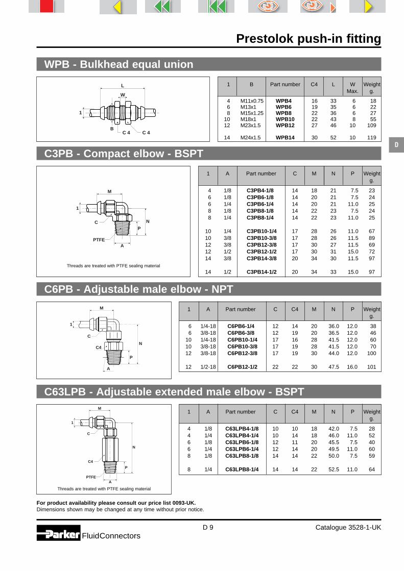
Prestolok push-in fitting
D 9 Catalogue 3528-1-UKFluidConnectors
D
For product availability please consult our price list 0093-UK.Dimensions shown may be changed at any time without prior notice.
1
L
W
C 4C 4B
WPB - Bulkhead equal union
1
M
N
PC
APTFE
C3PB - Compact elbow - BSPT
1
M
N
P
A
C
C4
PTFE
C63LPB - Adjustable extended male elbow - BSPT
Threads are treated with PTFE sealing material
Threads are treated with PTFE sealing material
1 A Part number C M N P Weightg.
4 1/8 C3PB4-1/8 14 18 21 17.5 236 1/8 C3PB6-1/8 14 20 21 17.5 246 1/4 C3PB6-1/4 14 20 21 11.0 258 1/8 C3PB8-1/8 14 22 23 17.5 248 1/4 C3PB8-1/4 14 22 23 11.0 25
10 1/4 C3PB10-1/4 17 28 26 11.0 6710 3/8 C3PB10-3/8 17 28 26 11.5 8912 3/8 C3PB12-3/8 17 30 27 11.5 6912 1/2 C3PB12-1/2 17 30 31 15.0 7214 3/8 C3PB14-3/8 20 34 30 11.5 97
14 1/2 C3PB14-1/2 20 34 33 15.0 97
1 A Part number C C4 M N P Weightg.
4 1/8 C63LPB4-1/8 10 10 18 42.0 17.5 284 1/4 C63LPB4-1/4 10 14 18 46.0 11.0 526 1/8 C63LPB6-1/8 12 11 20 45.5 17.5 406 1/4 C63LPB6-1/4 12 14 20 49.5 11.0 608 1/8 C63LPB8-1/8 14 14 22 50.0 17.5 59
8 1/4 C63LPB8-1/4 14 14 22 52.5 11.0 64
M
N
P
A
C
1
C4
C6PB - Adjustable male elbow - NPT
1 A Part number C C4 M N P Weightg.
6 1/4-18 C6PB6-1/4 12 14 20 36.0 12.0 386 3/8-18 C6PB6-3/8 12 19 20 36.5 12.0 46
10 1/4-18 C6PB10-1/4 17 16 28 41.5 12.0 6010 3/8-18 C6PB10-3/8 17 19 28 41.5 12.0 7012 3/8-18 C6PB12-3/8 17 19 30 44.0 12.0 100
12 1/2-18 C6PB12-1/2 22 22 30 47.5 16.0 101
1 B Part number C4 L W WeightMax. g.
4 M11x0.75 WPB4 16 33 6 186 M13x1 WPB6 19 35 6 228 M15x1.25 WPB8 22 36 6 27
10 M18x1 WPB10 22 43 8 5512 M23x1.5 WPB12 27 46 10 109
14 M24x1.5 WPB14 30 52 10 119

Prestolok push-in fitting
D 10 Catalogue 3528-1-UKFluidConnectors
D
For product availability please consult our price list 0093-UK.Dimensions shown may be changed at any time without prior notice.
C64PB - Adjustable male elbow - BSPP
1 B Part number C C4 J M N Weightg.
4 1/8 C64PB4-1/8 14 14 6 18 26.5 224 1/4 C64PB4-1/4 19 19 9 18 31.5 376 1/8 C64PB6-1/8 14 14 6 20 30.0 306 1/4 C64PB6-1/4 19 19 9 20 33.0 418 1/8 C64PB8-1/8 14 14 6 22 30.0 35
8 1/4 C64PB8-1/4 19 19 9 22 35.0 478 3/8 C64PB8-3/8 13 22 9 22 36.0 62
10 1/4 C64PB10-1/4 19 19 9 28 39.0 6610 3/8 C64PB10-3/8 22 22 9 28 40.0 8212 1/4 C64PB12-1/4 19 19 9 30 41.0 106
12 3/8 C64PB12-3/8 22 22 9 30 42.0 11014 3/8 C64PB14-3/8 22 22 9 34 46.0 15814 1/2 C64PB14-1/2 27 27 12 34 50.5 188
1
M
N
J
B
C
C 4
C64SPB - Compact adjustable male elbow - BSPP
1 B Part number C C4 J M N Weightg.
4 1/8 C64SPB4-1/8 13 13 6 17 18.0 196 1/8 C64SPB6-1/8 13 13 6 22 18.0 226 1/4 C64SPB6-1/4 16 13 9 22 21.5 288 1/8 C64SPB8-1/8 13 15 6 25 18.0 258 1/4 C64SPB8-1/4 16 15 9 25 21.0 32
8 3/8 C64SPB8-3/8 19 15 9 25 21.0 3610 1/4 C64SPB10-1/4 16 18 9 30 23.0 4010 3/8 C64SPB10-3/8 19 18 9 30 23.0 4912 1/4 C64SPB12-1/4 16 20 9 32 24.0 5112 3/8 C64SPB12-3/8 19 20 9 32 24.0 55
12 1/2 C64SPB12-1/2 24 20 12 32 29.0 80
M
1
C
C4 B
JN
1
M
N
P
C
C4
PTFEA
C63PB - Adjustable male elbow - BSPT
1 A Part number C C4 M N P Weightg.
4 1/8 C63PB4-1/8 10 10 18 26.5 17.5 194 1/4 C63PB4-1/4 10 14 18 30.0 11.0 276 1/8 C63PB6-1/8 12 11 20 28.0 17.5 256 1/4 C63PB6-1/4 12 14 20 31.0 11.0 358 1/8 C63PB8-1/8 14 14 22 30.0 17.5 33
8 1/4 C63PB8-1/4 14 14 22 33.0 11.0 408 3/8 C63PB8-3/8 14 17 22 34.5 11.5 51
10 1/4 C63PB10-1/4 17 17 28 40.0 11.0 5910 3/8 C63PB10-3/8 17 17 28 39.0 11.5 6512 1/4 C63PB12-1/4 22 19 30 42.0 11.0 105
12 3/8 C63PB12-3/8 22 19 30 41.0 11.5 10912 1/2 C63PB12-1/2 22 22 30 44.5 15.0 11814 3/8 C63PB14-3/8 25 22 34 46.0 11.5 15214 1/2 C63PB14-1/2 25 22 34 48.5 15.0 162
Threads are treated with PTFE sealing material

Prestolok push-in fitting
D 11 Catalogue 3528-1-UKFluidConnectors
D
For product availability please consult our price list 0093-UK.Dimensions shown may be changed at any time without prior notice.
C68SPB - Compact adjustable male elbow - metric straight thread
1 B Part number C C4 J M N Weightg.
4 M5x0.8 C68SPB4M5 10 12.5 5 17 18 166 M5x0.8 C68SPB6M5 10 12.5 5 17 18 17
1 B Part number C C4 L L1 M O W WeightMax. g.
4 M11x0.75 WE6PB4 14 16 37 18.0 18.0 11.5 6 286 M13x1 WE6PB6 17 17 39 19.5 20.5 13.5 6 508 M15x1.25 WE6PB8 19 19 43 21.5 22.5 15.5 6 65
10 M18x1 WE6PB10 22 22 54 29.0 28.5 18.5 8 12812 M23x1.5 WE6PB12 27 27 59 30.0 30.0 23.5 10 189
WE6PB - 90° adjustable bulkhead union elbow
EPB - Equal union elbow
1 Part number C M Weightg.
4 EPB4 10 18.0 125 EPB5 12 20.5 236 EPB6 12 20.0 198 EPB8 14 22.0 22
10 EPB10 17 28.0 38
12 EPB12 22 30.0 7314 EPB14 25 35.0 116
C68PB - Adjustable male elbow - metric straight thread
1 B Part number C C4 J M N Weightg.
4 M3x0.5 C68PB4M3 10 10 3.25 18 23.0 154 M5x0.8 C68PB4M5 10 10 5.00 18 24.5 166 M5x0.8 C68PB6M5 12 11 5.00 20 25.5 24
1
M
N
J
B
C
C 4
M
C
1
C4 BJ
N
1
M
L
L1
W
C 4
C
O
B
1
M
MC

Prestolok push-in fitting
D 12 Catalogue 3528-1-UKFluidConnectors
D
For product availability please consult our price list 0093-UK.Dimensions shown may be changed at any time without prior notice.
1 Part number C L M Weightg.
4 JPB4 10 36 18.0 165 JPB5 12 41 20.5 286 JPB6 12 40 20.0 228 JPB8 14 44 22.0 29
10 JPB10 17 56 28.0 57
12 JPB12 22 60 30.0 10014 JPB14 25 68 34.0 160
JPB - Equal union tee
R63PB - Adjustable male run tee - BSPT
1 A Part number C C4 L M N P Weightg.
4 1/8 R63PB4-1/8 10 10 44.5 18 26.5 17.5 234 1/4 R63PB4-1/4 10 14 48.0 18 30.0 11.0 316 1/8 R63PB6-1/8 12 11 48.0 20 28.0 17.5 286 1/4 R63PB6-1/4 12 14 51.0 20 31.0 11.0 388 1/8 R63PB8-1/8 14 14 52.0 22 30.0 17.5 40
8 1/4 R63PB8-1/4 14 14 55.0 22 33.0 11.0 468 3/8 R63PB8-3/8 14 17 56.5 22 34.5 11.5 58
10 1/4 R63PB10-1/4 17 17 68.0 28 40.0 11.0 7710 3/8 R63PB10-3/8 17 17 67.0 28 39.0 11.5 8412 1/4 R63PB12-1/4 22 19 72.0 30 42.0 11.0 132
12 3/8 R63PB12-3/8 22 19 71.0 30 41.0 11.5 13512 1/2 R63PB12-1/2 22 22 74.5 30 44.5 15.0 14414 3/8 R63PB14-3/8 25 22 80.0 34 46.0 11.5 19714 1/2 R63PB14-1/2 25 22 82.5 34 48.5 15.0 207
R64PB - Adjustable male run tee - BSPP
1 B Part number C C4 J L M N Weightg.
4 1/8 R64PB4-1/8 10 14 6 44.5 18 26.5 264 1/4 R64PB4-1/4 10 19 9 49.5 18 31.5 416 1/8 R64PB6-1/8 12 14 6 50.0 20 30.0 336 1/4 R64PB6-1/4 12 19 9 53.0 20 33.0 448 1/8 R64PB8-1/8 14 14 6 52.0 22 30.0 42
8 1/4 R64PB8-1/4 14 19 9 57.0 22 35.0 548 3/8 R64PB8-3/8 14 22 9 58.0 22 36.0 69
10 1/4 R64PB10-1/4 17 19 9 67.0 28 39.0 8510 3/8 R64PB10-3/8 17 22 9 68.0 28 40.0 10112 1/4 R64PB12-1/4 22 19 9 71.0 30 41.0 133
12 3/8 R64PB12-3/8 22 22 9 72.0 30 42.0 13614 3/8 R64PB14-3/8 25 22 9 80.0 34 46.0 20314 1/2 R64PB14-1/2 25 27 12 84.5 34 50.5 232
1
M
L
MC
1
NL
M
CC4
P
A
PTFE
1
B
N
L
M
J
CC 4
Threads are treated with PTFE sealing material

Prestolok push-in fitting
D 13 Catalogue 3528-1-UKFluidConnectors
D
R68PB - Adjustable male run tee - metric straight thread
1 B Part number C C4 J L M N Weightg.
4 M3x0.5 R68PB4M3 10 10 3.25 41.0 18 23.0 194 M5x0.8 R68PB4M5 10 10 5.00 42.5 18 24.5 206 M5x0.8 R68PB6M5 12 11 5.00 45.5 20 25.5 27
S63PB - Adjustable male branch tee - BSPT
1 A Part number C C4 L M N P Weightg.
4 1/8 S63PB4-1/8 10 10 36 18 26.5 17.5 234 1/4 S63PB4-1/4 10 14 36 18 30.0 11.0 316 1/8 S63PB6-1/8 12 11 40 20 28.0 17.5 286 1/4 S63PB6-1/4 12 14 40 20 31.0 11.0 388 1/8 S63PB8-1/8 14 14 44 22 30.0 17.5 40
8 1/4 S63PB8-1/4 14 14 44 22 33.0 11.0 468 3/8 S63PB8-3/8 14 17 44 22 34.5 11.5 58
10 1/4 S63PB10-1/4 17 17 56 28 40.0 11.0 7710 3/8 S63PB10-3/8 17 17 56 28 39.0 11.5 8412 1/4 S63PB12-1/4 22 19 60 30 42.0 11.0 132
12 3/8 S63PB12-3/8 22 19 60 30 41.0 11.5 13512 1/2 S63PB12-1/2 22 22 60 30 44.5 15.0 14414 3/8 S63PB14-3/8 25 22 68 34 46.0 11.5 19714 1/2 S63PB14-1/2 25 22 68 34 48.5 15.0 207
S64PB - Adjustable male branch tee - BSPP
1 B Part number C C4 J L M N Weightg.
4 1/8 S64PB4-1/8 10 14 6 36 18 26.5 264 1/4 S64PB4-1/4 10 19 9 36 18 31.5 416 1/8 S64PB6-1/8 12 14 6 40 20 30.0 336 1/4 S64PB6-1/4 12 19 9 40 20 33.0 448 1/8 S64PB8-1/8 14 14 6 44 22 30.0 42
8 1/4 S64PB8-1/4 14 19 9 44 22 35.0 548 3/8 S64PB8-3/8 14 22 9 44 22 36.0 69
10 1/4 S64PB10-1/4 17 19 9 56 28 39.0 8510 3/8 S64PB10-3/8 17 22 9 56 28 40.0 10112 1/4 S64PB12-1/4 22 19 9 60 30 41.0 133
12 3/8 S64PB12-3/8 22 22 9 60 30 42.0 13614 3/8 S64PB14-3/8 25 22 9 68 34 46.0 20314 1/2 S64PB14-1/2 25 27 12 68 34 50.5 232
S68PB - Adjustable male branch tee - metric straight thread
1 B Part number C C4 J L M N Weightg.
4 M3x0.5 S68PB4M3 10 10 3.25 36 18 23.0 194 M5x0.8 S68PB4M5 10 10 5.00 36 18 24.5 206 M5x0.8 S68PB6M5 12 11 5.00 40 20 25.5 27
Threads are treated with PTFE sealing material
1
N
J
L
MC
C 4
B
1
M
L
NC
C4 P
APTFE
1
B
M
L
N
J C 4
C
1
M
L
N
J C 4
C
B

Prestolok push-in fitting
D 14 Catalogue 3528-1-UKFluidConnectors
D
For product availability please consult our price list 0093-UK.Dimensions shown may be changed at any time without prior notice.
CORPB - Single banjo body only
1 Part number Part No. Part No. M X Y Weightsingle bolt stacking bolt g.
4 CORPB4-5 SC8UM5-4 SC8UDM5-4 19.0 10 10 84 CORPB4-10 SC4U1/8-4 SC4UD1/8-4 22.5 14 14 166 CORPB6-10 SC4U1/8-4 SC4UD1/8-4 23.0 14 14 176 CORPB6-13 SC4U1/4-6 SC4UD1/4-6 24.5 14 17 218 CORPB8-10 SC4U1/8-4 SC4UD1/8-4 24.0 14 14 44
8 CORPB8-13 SC4U1/4-6 SC4UD1/4-6 25.5 14 17 5910 CORPB10-17 SC4U3/8-10 SC4UD3/8-10 32.0 17 22 127
CORPBD - Double banjo body only
1 Part number Part No. Part No. L M X Y Weightsingle bolt stacking bolt g.
4 CORPB4D5 SC8UM5-4 SC8UDM5-4 38 19.0 10 10 134 CORPB4D10 SC4U1/8-4 SC4UD1/8-4 45 22.5 14 14 226 CORPB6D10 SC4U1/8-4 SC4UD1/8-4 46 23.0 14 14 236 CORPB6D13 SC4U1/4-6 SC4UD1/4-6 49 24.5 14 17 478 CORPB8D10 SC4U1/8-4 SC4UD1/8-4 48 24.0 14 14 61
1 B Part number C D J K L M N O Y Weightg.
4 M5x0.8 COR8PB4M5 8 8.2 4.5 1.0 24.0 19.0 13.5 6.0 10 184 1/8 COR4PB4-1/8 14 14.4 6.0 1.5 29.5 22.5 19.5 8.5 14 316 1/8 COR4PB6-1/8 14 14.4 6.0 1.5 30.0 23.0 19.5 8.5 14 326 1/4 COR4PB6-1/4 17 18.4 9.0 2.0 33.0 24.5 21.0 9.0 17 488 1/8 COR4PB8-1/8 14 14.4 6.0 1.5 31.0 34.0 19.5 8.5 14 58
8 1/4 COR4PB8-1/4 17 18.4 9.0 2.0 34.0 25.5 21.0 9.0 17 8610 3/8 COR4PB10-3/8 22 21.6 9.0 2.5 43.0 32.0 25.5 11.0 22 122
COR8PB/COR4PB - Single banjo - assembled
These parts are delivered complete with sealing washer.
Banjo or double banjo fittings with banjo or stacking banjo boltspermit space-saving connections and can be used where themounting of elbows is not possible.
B
D
K ON
J
C
1
L
M
Y
1
M
X
Y
1 1
M
L
X
Y

Prestolok push-in fitting
D 15 Catalogue 3528-1-UKFluidConnectors
D
For product availability please consult our price list 0093-UK.Dimensions shown may be changed at any time without prior notice.
1 B Part number C D J K L M N O Y Weightg.
4 M5x0.8 COR8PB4DM5 8 8.2 4.5 1.0 38.0 19.0 13.5 6.0 10 234 1/8 COR4PB4D1/8 14 14.4 6.0 1.5 45.0 22.5 19.5 8.5 14 376 M10x1 COR8PB6M10 14 14.5 8.0 1.5 30.8 23.1 19.7 8.5 14 356 M12x1.5 COR8PB6M12 17 17.5 10.0 2.0 33.9 24.6 21.0 9.0 14 406 1/8 COR4PB6D1/8 14 14.4 6.0 1.5 46.0 23.0 19.5 8.5 14 38
6 1/8 COR4PB6D1/4 17 18.4 9.0 2.0 49.0 24.5 21.0 9.0 17 758 1/8 COR4PB8D1/8 14 14.4 6.0 1.5 48.0 24.0 19.5 8.5 14 76
COR8PBD/COR4PBD - Double banjo - assembled
B Part number C D J K L Weightg.
M5x0.8 SC8UM5-4 8 8.2 4.5 1.0 18.5 101/8 SC4U1/8-4 14 14.4 6.0 1.5 25.5 151/4 SC4U1/4-6 17 18.4 9.0 2.0 30.0 273/8 SC4U3/8-10 22 21.6 9.0 2.5 34.5 124
SC8UD/SC4UD - Stacking banjo bolt with seals
SC8U/SC4U - Single banjo bolt with seals
B Part number C D J K L Weightg.
M5x0.8 SC8UDM5-4 8 8.2 4.5 1.0 29.5 161/8 SC4UD1/8-4 14 14.4 6.0 1.5 41.0 19
1/4 SC4UD1/4-6 17 18.4 9.0 2.0 46.0 28
These parts are delivered complete with sealing washer.
B
D
K
L
J
C
B
D
K ON
J
C
1
L
M
Y
B
D
K
L
J
C

Prestolok push-in fitting
D 16 Catalogue 3528-1-UKFluidConnectors
D
For product availability please consult our price list 0093-UK.Dimensions shown may be changed at any time without prior notice.
TEPB - Tube end expander
FNPB - Plug
1 2 Part number L L1 Weightg.
4 6 TEPB4-6 39 19 7
1 2 Part number L L1 Weightg.
6 4 TRPB6-4 40.0 22 88 4 TRPB8-4 39.5 22 108 6 TRPB8-6 41.5 22 10
10 4 TRPB10-4 37.0 27 2710 6 TRPB10-6 43.0 27 15
10 8 TRPB10-8 47.5 27 1612 6 TRPB12-6 38.0 27 2312 8 TRPB12-8 44.0 27 1712 10 TRPB12-10 52.0 27 2014 8 TRPB14-8 41.0 30 31
14 10 TRPB14-10 51.0 30 2314 12 TRPB14-12 55.0 30 36
TRPB - Tube end reducer
T23HFPB - Tube end male adaptor - BSPT
1 A Part number C L N P Weightg.
5 1/8 T23HFPB5-1/8 10 31.5 20 17.5 125 1/4 T23HFPB5-1/4 14 36.0 20 11.0 26
1 Part number L Weightg.
4 FNPB4 27 26 FNPB6 27 58 FNPB8 30 12
10 FNBP10 30 2312 FNBP12 35 3514 FNBP14 36 46
Threads are treated with PTFE sealing material
2
L
L 1
1
1
L
N P
A
CPTFE
2
L
L 1
1
L
1

Prestoweld 2Spark resistant push-in fittings
Catalogue 3528-5-UK

E
Prestoweld 2 push-in fitting
E 2 Catalogue 3528-5-UKFluidConnectors
Index
Straightconnectors& bulkhead unions
Male connector Male connectorBSPP metric Equal union Equal bulkhead unionF4PWB - p. E 4 F8PWB - p. E4 HPWB - p. E4 WPWB - p. E 5
90° elbows& tees
Equal union tee Male elbow - BSPP Equal elbow unionJPWB - p. E 5 C64PWB - p. E 5 EPWB - p. E 6
Adaptors/accessories
Plug Tube end expanderFNPB - p. E 6 TRPWB - p. E 6
Technical tubing Please consult Thermoplastic single tubes and Pneumo-Tube bundles section (P).

E
Prestoweld 2 push-in fitting
E 3 Catalogue 3528-5-UKFluidConnectors
Principle
Prestoweld 2 push-in welding fittings have been specificallydesigned to meet the stringent requirements of the roboticwelding industry for pneumatic controls.
Developed from the Prestolok push-in fitting, Prestoweld 2uses “elastic teeth” grab ring technology which guaranteesexcellent tube retention particularly critical in theseapplications.
Prestoweld 2 is designed for use with weld spark resistantpolyurethane halogene free Parker Prestoweld 2 tubing. It featuresa special polyamide Starflam U2Z22/8 push-button design whichresist to sparks and weld spatter and prevents tube damaging.
Prestoweld 2 fittings are perfectly designed for use withpneumatic systems in the robotics industry.
Technical features
Brass nickel plated bodyBrass is a raw material providing:- robustness,- excellent shock resistance,- good temperature capability,- excellent spark resistance.Nickel plating gives improved corro-sion resistance and a brightappearance which does notdeteriorate.
Protective push-button- the unique design of the Prestoweld 2
polyamide Starflam U2Z22/8 push-button and its thermic propertiesprevent damages from sparks and weldspatter.
- simple manual pressure on thepush button allows instant discon-nection of the tube.
- the tube size are marked on the pushbutton for easy identification.
Ready-to-use fittingThe Prestoweld 2 range containsready to use fittings equiped by BSPPadaptors with unloosable o-ring.- this fitting do not need tubing
preparation.- the Prestoweld 2 tubing allow a low
bend radius for a best space saving.
Body Threaded Sleeve Grab Push Back-up O-ringparts ring button washer
Nickel Nickel Brass Stainless Polyamide Brass Nitrile From 0.01 From -25°Cplated plated steel STARFLAM to tobrass brass U2Z22/8 25 bar +100°C
Material
1 2 3 4 5 6 7 Working Workingpressure temperature
Advantages
Full flow capabilities Compact installationSpark resistant Wide range

E
Prestoweld 2 push-in fitting
E 4 Catalogue 3528-5-UKFluidConnectors
F4PWB - Male connector - BSPP
1 B Part number C4 J L H WeightInt. g.
4 M5x0.8 F8PWB4M5 10 5 25.3 2.5 16
1 Part number L 0 Weightg.
4 HPWB4 32.5 10 116 HPWB6 35.6 12 138 HPWB8 38.0 14 18
10 HPWB10 48.8 17 2712 HPWB12 48.8 21 5814 HPWB14 54.6 22 71
C 4J
1 B
L
1
L
JC 4
B
L
1O
1 B Part number C4 J L H WeightInt. g.
4 1/8 F4PWB4-1/8 13 6 21.7 3 164 1/4 F4PWB4-1/4 16 9 23.3 3 276 1/8 F4PWB6-1/8 13 6 25.3 4 176 1/4 F4PWB6-1/4 16 9 26.0 4 248 1/8 F4PWB8-1/8 14 6 27.4 4 24
8 1/4 F4PWB8-1/4 16 9 27.4 6 298 3/8 F4PWB8-3/8 20 9 28.0 6 59
10 1/4 F4PWB10-1/4 17 9 35.4 6 5010 3/8 F4PWB10-3/8 20 9 31.4 8 3910 1/2 F4PWB10-1/2 24 12 30.3 8 60
12 1/4 F4PWB12-1/4 20 9 36.0 6 4912 3/8 F4PWB12-3/8 20 9 35.7 8 4912 1/2 F4PWB12-1/2 24 12 34.1 10 7214 3/8 F4PWB14-3/8 22 9 38.3 8 6614 1/2 F4PWB14-1/2 24 12 37.4 10 81
F8PWB - Male connector - Metric
HPWB - Equal union
For product availability please consult our price list 0093-UKDimensions shown may be changed at any time without prior notice.

E
Prestoweld 2 push-in fitting
E 5 Catalogue 3528-5-UKFluidConnectors
1 Part number C L M Weightg.
6 JPWB6 12 41.0 20.5 228 JPWB8 14 45.4 22.7 29
10 JPWB10 17 57.2 28.6 5712 JPWB12 22 60.4 30.2 100
For product availability please consult our price list 0093-UKDimensions shown may be changed at any time without prior notice.
1 B Part number C4 J 0 W Weightmax g.
6 M13x1 WPWB6 17 35.6 13 6 228 M15x1.25 WPWB8 19 38.0 15 6 27
10 M18x1 WPWB10 22 47.8 18 8 5512 M23x1.5 WPWB12 27 48.9 23 10 109
1
ML
MC
1
M
N
J
B
C
C 4
WPWB - Equal bulkhead union
C64PWB - Adjustable male elbow BSPP
JPWB - Equal union tee
1 B Part number C C4 J M N Weightg.
6 1/8 C64PWB6-1/8 12 14 6 20.5 27.4 326 1/4 C64PWB6-1/4 12 19 9 20.5 32.4 418 1/8 C64PWB8-1/8 14 14 6 22.7 29.6 358 1/4 C64PWB8-1/4 14 19 9 22.7 34.6 478 3/8 C64PWB8-3/8 14 22 9 22.7 35.6 62
10 1/4 C64PWB10-1/4 17 19 9 28.6 39.2 6610 3/8 C64PWB10-3/8 17 22 9 28.6 40.2 8212 1/4 C64PWB12-1/4 22 19 9 30.2 40.8 10612 3/8 C64PWB12-3/8 22 22 9 30.2 41.8 110
1
LW
C 4C 4B
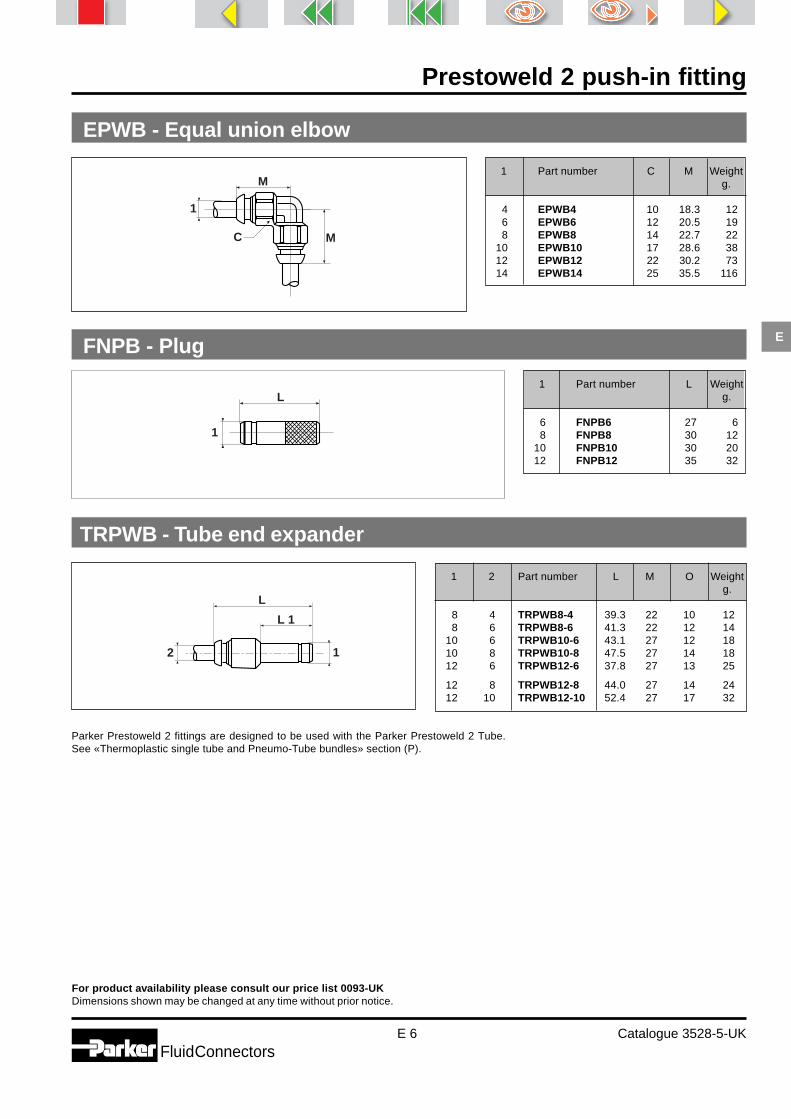
E
Prestoweld 2 push-in fitting
E 6 Catalogue 3528-5-UKFluidConnectors
For product availability please consult our price list 0093-UKDimensions shown may be changed at any time without prior notice.
1 Part number L Weightg.
6 FNPB6 27 68 FNPB8 30 12
10 FNPB10 30 2012 FNPB12 35 32
Parker Prestoweld 2 fittings are designed to be used with the Parker Prestoweld 2 Tube.See «Thermoplastic single tube and Pneumo-Tube bundles» section (P).
2
L
L 1
1
1 2 Part number L M O Weightg.
8 4 TRPWB8-4 39.3 22 10 128 6 TRPWB8-6 41.3 22 12 14
10 6 TRPWB10-6 43.1 27 12 1810 8 TRPWB10-8 47.5 27 14 1812 6 TRPWB12-6 37.8 27 13 25
12 8 TRPWB12-8 44.0 27 14 2412 10 TRPWB12-10 52.4 27 17 32
L
1
FNPB - Plug
TRPWB - Tube end expander
1 Part number C M Weightg.
4 EPWB4 10 18.3 126 EPWB6 12 20.5 198 EPWB8 14 22.7 22
10 EPWB10 17 28.6 3812 EPWB12 22 30.2 7314 EPWB14 25 35.5 116
1
M
MC
EPWB - Equal union elbow

Pneumatic integratedfunction fittings
Catalogue 0019-5-UK

Pneumatic integrated function fittings
F 2 Catalogue 0019-5-UKFluidConnectors
F
IndexPrestoflowBanjo flow regulator -compact
with push-in connectionmetric boltPTF8PB / PTFA8PB - p. F 9
PrestoflowBanjo flow regulator -with locknut
with push-in connectionmetric boltPTFL8PB - p. F 13
PrestoflowBanjo flow regulator -swivel outlet
with push-in connectionmetric boltPTF8E6PB - p. F 11
PrestoflowFlow regulator -In-line
with push-in connectionBSPP boltPTF4PB / PTFA4PB - p. F 9
with threaded connectionBSPP boltPTF4 - p. F 9
with push-in connectionBSPP boltPTFL4PB - p. F 13
with threaded connection/metric boltPTFL8 / PTFAL8 - p. F 13
with threadedconnection - BSPP boltPTFL4 - p. F 13
with push-in connectionPTFIPK - p. F 15
with push-in connectionultrafine adjustmentPTFMIPK - p. F 15
with push-in connectionPTFIWPK - p. F 15
with push-in connectionBSPP boltPTF4E6PB - p. F 11
with compressionconnectionBSPP boltPTFL4COB - p. F 13
with spark resistant push-inconnection - BSPP boltPTF4PBW - p. F 10
with push-in connectionmetric boltPTFAL8PB - p. F 12
Prestoflowcompact and micro
with push-in connectionBSPP / metric boltPTFC4/8PK - p. F 16
with push-in connectionBSPP / metric boltPTFAC4/8PK - p. F 16
with push-in connectionBSPP boltPTFLC4PK - p. F 16
with push-in connectionBSPP boltPTFLAC4PK - p. F 17
with push-in connectionmetric boltPTFLM8PK - p. F 17
with push-in connectionmetric boltPTFALM8PK - p. F 17
NEW NEW NEW NEW
NEW NEW

Pneumatic integrated function fittings
F 3 Catalogue 0019-5-UKFluidConnectors
F
Index
Prestotwin
with push-in connectionBSPP bolt / barrel adjustmentPWR-HB - p. F 23
with push-in connectionBSPP bolt / barrel adjustmentPWR-HE - p. F 23
PrestosensorPressuresensors
with push-in connectionBSPP and metric boltPTP4/8PB - p. F 24
with threaded connectionBSPP and metric boltPTP4/8 - p. F 25
plug-in sensorelectrical outputPWS-M - p. F 25
plug-in sensorelectronical outputPWS-E - p. F 25
banjo socketwith sensor locking clipPWS-B - p. F 25
PrestostartPneumaticslow startfittings
with push-in connectionBSPP boltPCV4PK - p. F 27
with threaded connectionBSPP boltPCV4 - p. F 27
with push-in connectionBSPP boltPIV4PK- p. F 27
with threaded connectionBSPP boltPIV4 - p. F 27
PrestoreducePressurereducers
with push-in connectionBSPP boltPRB4PB - p. F 29
with threaded connectionBSPP boltPRB4 - p. F 29
with push-in connectionBSPP boltPRIPB - p. F 29
with threaded connectionBSPP boltPRI4 - p. F 29
in-line version
PrestosilFlow regulator+ silencer
andAccessories
with threadedconnection - BSPPPRS - p. F 30
in-line Prestoflowassembly clipClip - p. F 31
manual ratchet controlfor pressure reducersRatchet - p. F 31
sealing plug forpressure reducersSplug - p. F 31
pressure gaugefor push-in fittingP Gauge - p. F 31
flow regulator + blocker flow regulator + unloader
pneumatic output electrical output electronic output
power valve version
banjo version
0 10
2
4 6
8
bar
non-returnequal unionPWA-L - p. F 31
with push-in connectionBSPP boltPWB-A - p. F 19
with threaded connectionBSPP boltPWB-A - p. F 19
with push-in connectionBSPP boltPWE-A - p. F 21
with threaded connectionBSPP boltPWE-A - p. F 21
Blockers UnloadersPrestoblocandPrestoload
NEW
system isolating version

Pneumatic integrated function fittings
F 4 Catalogue 0019-5-UKFluidConnectors
F
Product family Symbol Function Part number
PTFPB
Prestoflow - Flow regulatorexhaustflow control
inlet flowcontrol
in-lineflow control
Prestoflow flow control regulators aredesigned to adjust the speed of thecylinder piston rod by controlling the flowof air. They are unidirectional and arenormally installed on the exhaust port ofthe cylinder. For specific applications,they could be mounted in-line or on theinlet port.Compact and micro series are speciallydesigned where space saving is apriority.
PTF ........ p. F 9
PTFE6 .... p. F 11
PTFL ...... p. F 12
PTFI ....... p. F 15
PTFC ...... p. F 16
PTFLC.... p. F 16
PTFLM ... p. F 17
Prestobloc - Blocker
Prestobloc is a pneumatically controlledcheck valve for mounting onto thecylinder port. It is designed to block themovement of the piston rod at selectedpositions.As a safety device it prevents theexhausting of air from the cylinder in theevent of a power failure.
PWB-A ...... p. F 19
Prestoload - Unloader
PWE-A
PWB-A
Prestoload is a pneumatically controlledexhaust valve for direct mounting ontothe cylinder ports.It allows the rapid exhaust of air from thecylinder returning the piston rod to theinitial position.
PWE-A ...... p. F 21
PrestotwinFlow regulator + blockerFlow regulator + unloader
Prestotwin fittings combine flow controlwith blocking function or unloadingfunction. This concept allows a morecompact installation and saves assemblytime.
PWR-HB..... p. F 23
PWR-HE ..... p. F 23
block + control
unload + control
PWR-HE
PWR-HB
PTFL PTFIPK
PTFE6PB
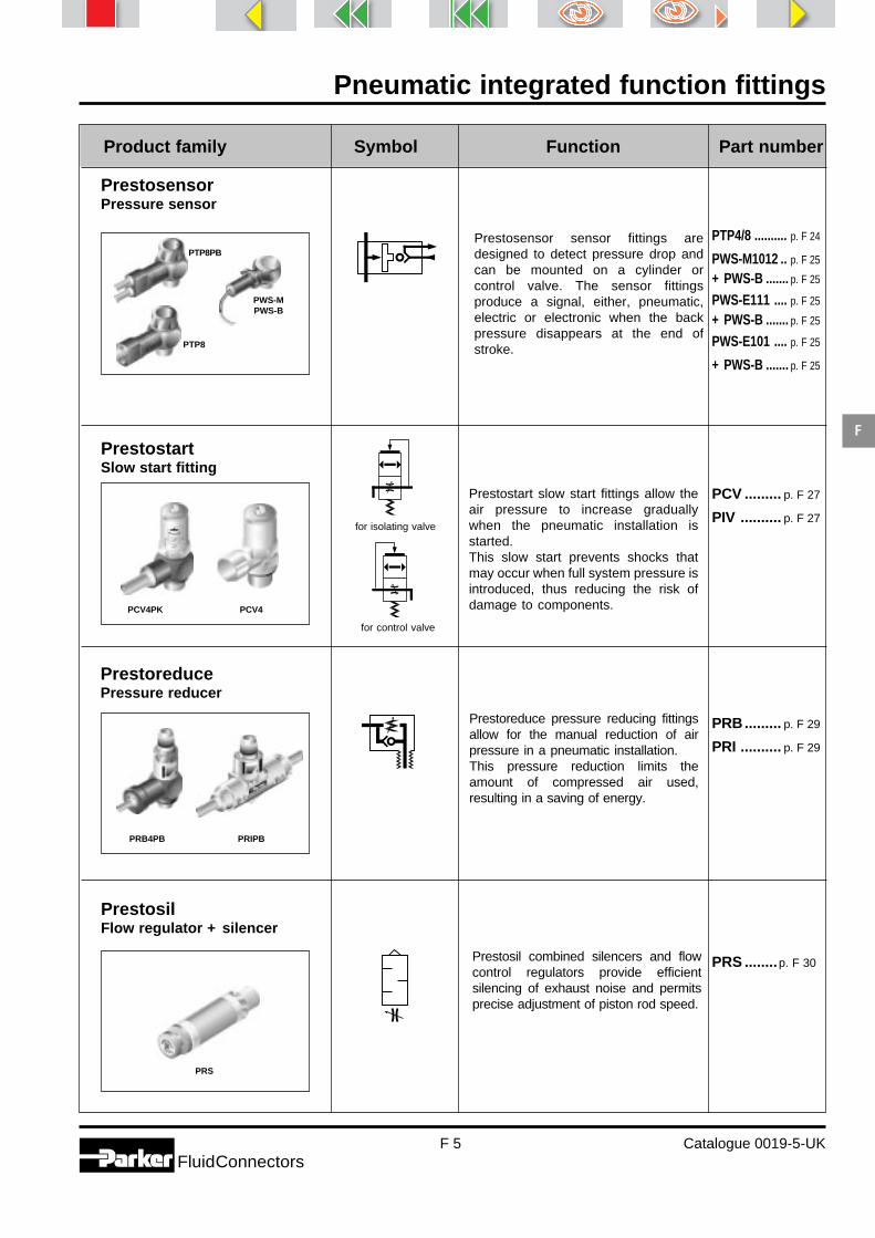
Pneumatic integrated function fittings
F 5 Catalogue 0019-5-UKFluidConnectors
F
Product family Symbol Function Part number
PrestosensorPressure sensor
Prestosensor sensor fittings aredesigned to detect pressure drop andcan be mounted on a cylinder orcontrol valve. The sensor fittingsproduce a signal, either, pneumatic,electric or electronic when the backpressure disappears at the end ofstroke.
PTP4/8 .......... p. F 24
PWS-M1012 .. p. F 25
+ PWS-B ....... p. F 25
PWS-E111 .... p. F 25
+ PWS-B ....... p. F 25
PWS-E101 .... p. F 25
+ PWS-B ....... p. F 25
PrestostartSlow start fitting
Prestostart slow start fittings allow theair pressure to increase graduallywhen the pneumatic installation isstarted.This slow start prevents shocks thatmay occur when full system pressure isintroduced, thus reducing the risk ofdamage to components.
PCV ......... p. F 27
PIV .......... p. F 27
PrestoreducePressure reducer
Prestoreduce pressure reducing fittingsallow for the manual reduction of airpressure in a pneumatic installation.This pressure reduction limits theamount of compressed air used,resulting in a saving of energy.
PRB......... p. F 29
PRI .......... p. F 29
PrestosilFlow regulator + silencer
Prestosil combined silencers and flowcontrol regulators provide efficientsilencing of exhaust noise and permitsprecise adjustment of piston rod speed.
PRS ........p. F 30
PCV4PK PCV4
PRB4PB PRIPB
PRS
for isolating valve
for control valve
PTP8PB
PWS-MPWS-B
PTP8

Pneumatic integrated function fittings
F 6 Catalogue 0019-5-UKFluidConnectors
F
Prestoflow - Flow regulators
Parker offer a wide range of flowregulators to meet a large variety ofapplications.Prestoflow can be fitted directly to acylinder port or mounted in the line.Prestoflow regulators with push-interminations are suitable for use witha wide range of plastic tubing.Prestoflow regulators with threadedterminations can be adapted for usewith copper and steel tubing orhoses.
General principleThe piston rod moves as a result ofthe pressure differential either side ofthe piston. The speed of the rod isnormally determined by the exhaustair flow from the cylinder. The controlof this air flow is via an adjustableneedle valve installed on the exhaustport.On single acting cylinders and someminiature (M5) double acting cylinders,the air flow can be controlled from theinlet port.To permit regular and smooth movementof the piston rod, flow control should bemade as near to the cylinder aspossible.
Flow regulation on the exhaust port Flow regulation on the inlet port
Flow control on a double acting cylinder
OperationThe mounting of two flow controldevices on a cylinder permits speedcontrol of the cylinder rod in both di-rections.The sketch opposite shows a cylinderwith inlet air at port A. Air passesfreely through the flow control valve A,with the check valve in the openposition. The exhaust is controlled bythe flow control fitting B, where thecheck valve in the closed positionforces the air to go through theadjustable needle valve. The functionof A and B are reversed when inlet airis applied to port B.
A B
▼
PTFPB
PTFIPK
PTFL
PTFE6PB
Inletchamber
Outletchamber
Inlet Exhaust
Inletchamber
Outletchamber
Inlet Exhaust

Pneumatic integrated function fittings
F 7 Catalogue 0019-5-UKFluidConnectors
F
Flow characteristicsPrestoflow pneumatic integratedfittings are designed to permit maxi-mum flow in both directions. This fullflow in both directions, together withthe very precise setting of the screw,permits a wide range of adjustmentbetween the minimum and maxi-mum speeds. The sketch oppositeshows the flow progressionaccording to the adjustment of thescrew.
To ensure a leak free connection forport mounted regulators the regulatorbolt should be tightened in accordancewith the table opposite.
Assembly torque
Thread Min.Nm
Max.Nm
Flow regulators - assembly torques
M5 0.2 0.51/8 6 91/4 10 153/8 14 221/2 30 42
Feature
Selection guide
Adjustment turns
Flow
Inlet
Out
let
20% 40% 60% 80% 100%
PTF series PTFL series PTFE6 series PTFI series
Mounting Direct Yes Yes Yes -Inline - - - Yes
Control Outlet Yes Yes Yes YesInlet Yes Yes - -
Tube connection Push-in 4 mm - 12 mm 4 mm - 12 mm 4 mm - 8 mm 4 mm - 12 mmcompression - 6 mm - 18 mm - -Threaded-Female 1/8 - 1/2 BSPP 1/8 - 1/2 BSPP - -
Bolt terminations M5 M5 M5 -1/8 - 1/2 BSPP 1/8 - 1/2 BSPP 1/8 - 3/8 BSPP -
Working pressure Bar 1 - 10 1 - 10 1 - 10 1 - 10Working temperature °C -25°C - +100°C -25°C - +100°C -25°C - +70°C -15°C - +70°CBody material Brass Brass Brass High resistance polyamide
Adjustment screw material Brass Brass Brass Brass-Duralumin (Ultrafine adjust)
Locknut No Yes No YesPanel mounting - - - YesBank mounting - - - YesSwivel Outlet - - Yes -

Pneumatic integrated function fittings
F 8 Catalogue 0019-5-UKFluidConnectors
F
Prestoflow - Flow regulator - Compact series
PrinciplePrestoflow compact flow regulators are designed for mounting directly onto cylinder ports to provide precisecontrol of piston rod speed. Thanks to their compactness they are particularly suitable for applications where spaceis at a premium. These unidirectional flow regulators are available for exhaust or inlet flow control.
Bodymaterial
Boltmaterial
Boltthread
Sealingdevice Terminations
Workingtemperature
Workingpressure
Brassblackepoxycoated
Brass
M51/8 BSPP1/4 BSPP3/8 BSPP1/2 BSPP
M5Nylon
washer
1/8 - 1/2 BSPP+ M5
Female threadDIN 3852 long
From - 25°Cto
+ 100°C
From 1to
10 bar
Flow adjustmentFlow control is adjusted withan Allen key.
The large number of turns fromfully closed to fully open allowsfor precise flow control.
Technical features
- A check valve blocks the fullflow ports in the exhaust orinlet direction.
- The flow is controlled by aneedle valve fitted in theregulator bolt.
1/8 - 1/2 BSPPNitrile
E. D. seal
4 mm - 12 mmpush-in
connection
Exhaust flowcontrol
Inlet flowcontrol
Adjustment screw
Check valve
Cylinder
To powervalve

Pneumatic integrated function fittings
F 9 Catalogue 0019-5-UKFluidConnectors
F
For product availability please consult our price list 0093-UK.Dimensions shown may be changed at any time without prior notice.
PTF4/8PB - Flow regulator with push-in connection
PTFA4/8PB - Flow regulator with push-in connection
PTF4 - Flow regulator with threaded connection
* These fittings are supplied with Nylon seal.
* These fittings are supplied with Nylon seal.
Parker Prestoflow with push-in connections are designed to be used with Parker calibrated polyamide or polyurethanetubing. See Thermoplastic singles tubes & Pneumo-Tube bundles section (P).
Exhaust flow control
Inlet flow control
Exhaust flow control
1 B Part number C5 D G1 H1 J M M1 N N1 O Y Weightg.
4 M5x0.8 PTF8PB4M5* 8 1.65 10.0 1.5 4 19.5 24.5 6.3 22.0 10 10 144 1/8 PTF4PB4-1/8 14 3.00 14.4 2.0 6 22.0 30.1 10.7 34.5 10 14 356 M5x0.8 PTF8PB6M5* 8 1.65 10.0 1.5 4 20.5 26.5 7.3 24.5 12 12 196 1/8 PTF4PB6-1/8 14 3.20 14.4 2.0 6 23.5 31.6 10.7 34.5 12 14 376 1/4 PTF4PB6-1/4 17 5.20 18.4 4.0 7 25.0 34.9 13.8 41.0 12 17 65
6 3/8 PTF4PB6-3/8 22 5.50 21.6 4.0 7 28.0 40.7 17.3 51.0 12 22 1428 1/8 PTF4PB8-1/8 14 3.20 14.4 2.0 6 25.0 33.1 10.7 34.5 14 14 438 1/4 PTF4PB8-1/4 17 5.20 18.4 4.0 7 28.5 38.3 13.8 41.0 14 17 708 3/8 PTF4PB8-3/8 22 6.00 21.6 4.0 7 29.5 42.2 17.3 51.0 14 22 146
10 1/4 PTF4PB10-1/4 17 5.20 18.4 4.0 7 31.5 41.3 13.8 41.0 17 17 67
10 3/8 PTF4PB10-3/8 22 6.00 21.6 4.0 7 34.0 46.7 17.3 51.0 17 22 13110 1/2 PTF4PB10-1/2 27 8.00 26.5 4.0 9 36.5 52.1 20.1 61.0 17 27 23112 3/8 PTF4PB12-3/8 22 6.00 21.6 4.0 7 34.0 46.7 17.3 51.0 20 22 20012 1/2 PTF4PB12-1/2 27 8.50 26.5 4.0 9 36.5 52.1 20.1 61.0 20 27 232
1 B Part number C5 D G1 H1 J M M1 N N1 O Y Weightg.
4 M5x0.8 PTFA8PB4M5* 8 1.65 10.0 1.5 4 19.5 24.5 6.3 22.0 10 10 144 1/8 PTFA4PB4-1/8 14 3.00 14.4 2.0 6 22.0 30.1 10.7 34.5 10 14 356 M5x0.8 PTFA8PB6M5* 8 1.65 10.0 1.5 4 20.5 26.5 7.3 24.5 12 12 196 1/8 PTFA4PB6-1/8 14 3.20 14.4 2.0 6 23.5 31.6 10.7 34.5 12 14 376 1/4 PTFA4PB6-1/4 17 5.20 18.4 4.0 7 25.0 34.9 13.8 41.0 12 17 65
8 1/8 PTFA4PB8-1/8 14 3.20 14.4 2.0 6 25.0 33.1 10.7 34.5 14 14 438 1/4 PTFA4PB8-1/4 17 5.20 18.4 4.0 7 28.5 38.3 13.8 41.0 14 17 70
B B1 Part number C5 D G1 H1 J LU M M1 N N1 O Y Weightg.
1/8 1/8 PTF4-1/8 14 3.2 14.4 2 6 8.5 17.5 25.6 10.7 34.5 13.9 14 381/4 1/4 PTF4-1/4 17 5.2 18.4 4 7 12.5 24.5 34.3 10.7 34.5 16.9 17 853/8 3/8 PTF4-3/8 22 6.0 21.6 4 7 12.5 27.5 40.2 13.8 41.0 21.6 22 2601/2 1/2 PTF4-1/2 27 8.5 26.5 4 9 14.5 33.5 49.1 17.3 51.0 26.5 27 323
N1
N
J
B
D
G1
M
M1
C5
H1
Y
1O
N1
N
J
B1
D
G1
LU
M
M1
C5
H1
Y
BO
N1
N
J
B
D
G1
M
M1
C5
H1
Y
1O

Pneumatic integrated function fittings
F 10 Catalogue 0019-5-UKFluidConnectors
F
PTF4PWB - Flow regulator with spark resistant push-in connection
For product availability please consult our price list 0093-UK.Dimensions shown may be changed at any time without prior notice.
NEW
1 B Part number C5 D G1 H1 J M M1 N N1 O Y Weightg.
6 1/8 PTF4PWB6-1/8 14 3.2 14.4 2.0 6 23.5 31.6 10.7 34.5 12 14 396 1/4 PTF4PWB6-1/4 17 5.2 18.4 4.0 7 25.0 34.9 13.8 41.0 12 17 678 1/8 PTF4PWB8-1/8 14 3.2 14.4 2.0 6 25.0 33.1 10.7 34.5 14 14 458 1/4 PTF4PWB8-1/4 17 5.2 18.4 4.0 7 28.5 38.3 13.8 41.0 14 17 708 3/8 PTF4PWB8-3/8 22 6.0 21.6 4.0 7 29.5 42.2 17.3 51.0 14 22 148
10 1/4 PTF4PWB10-1/4 17 5.2 18.4 4.0 7 31.5 41.3 13.8 41.0 17 17 7010 3/8 PTF4PWB10-3/8 22 6.0 21.6 4.0 7 34.0 46.7 17.3 51.0 17 22 13312 3/8 PTF4PWB12-3/8 22 6.0 21.6 4.0 7 34.0 46.7 17.3 51.0 20 22 20212 1/2 PTF4PWB12-1/2 27 8.5 26.5 4.0 9 36.5 52.1 20.1 61.0 20 27 234
N1
N
J
B
D
G1
M
M1
C5
H1
Y
1O

Pneumatic integrated function fittings
F 11 Catalogue 0019-5-UKFluidConnectors
F
Prestoflow - Flow regulator - Swivel outlet
Technical features
- A check valve blocks the full flowports in the exhaust direction.
- The flow is controlled by a needlevalve fitted in the regulator bolt.
- The swivel outlet can be posi-tioned in the most suitabledirection.
PrinciplePrestoflow unidirection swivel flow regulators are designed for mounting directly onto the cylinder exhaust port andprovide precise control of the piston rod speed. The swivel outlet is designed to allow vertical or oblique tube exitwhere access is restricted.
Flow adjustmentFlow control is adjusted with an Allen key.The large number of turns from fully closed to fully open allows for precise flow control.
Swivelelbow
material
Boltthreads
Sealing deviceTerminations
Workingtemperature
Workingpressure
Brassblackepoxycoated
Highresistancepolyamide
M51/8 BSPP1/4 BSPP3/8 BSPP
Nylonwasher
1/8 - 3/8 BSPPNitrile
E. D. seal
4 - 8 mmpush-in
From - 25°Cto
+ 70°C
From 1to
10 bar
Brass
Boltmaterial
Brass
Adjustmentscrew
PTF4/8E6PB - Flow regulator with push-in connection
* These fittings are supplied with Nylon seal.
Parker Prestoflow with push-in connections are designed to be used with Parker calibrated polyamide orpolyurethane tubing. See Thermoplastic singles tubes & Pneumo-Tube bundles section (P).
1 B Part number C5 D G1 H1 J M M2 N N1 P Y Weightg.
4 M5x0.8 PTF8E6PB4M5* 8 1.65 10.0 1.5 4 11.7 18.4 6.2 22.5 20.5 10 164 1/8 PTF4E6PB4-1/8 14 3.00 14.4 2.0 6 14.3 30.0 10.7 34.5 20.5 14 376 M5x0.8 PTF8E6PB6M5* 8 1.65 10.0 1.5 4 12.7 20.4 7.2 24.5 23.0 12 206 1/8 PTF4E6PB6-1/8 14 3.20 14.4 2.0 6 15.3 31.0 10.7 34.5 23.0 14 386 1/4 PTF4E6PB6-1/4 17 5.20 18.4 4.0 7 17.3 35.0 13.8 41.0 23.0 17 70
6 3/8 PTF4E6PB6-3/8 22 5.50 21.6 4.0 7 19.8 40.0 17.3 51.0 23.0 22 1328 1/8 PTF4E6PB8-1/8 14 3.20 14.4 2.0 6 16.8 33.5 10.7 34.5 25.0 14 408 1/4 PTF4E6PB8-1/4 17 5.20 18.4 4.0 7 18.3 37.0 13.8 41.0 25.0 17 738 3/8 PTF4E6PB8-3/8 22 6.00 21.6 4.0 7 20.8 42.0 17.3 51.0 25.0 22 136
Boltmaterial
N1
N
J
P
B
D
G1
1
M
M2
C5
H1
Y
180°
Fine threadadjustment screw
Check valve
Cylinder
To power valve

Pneumatic integrated function fittings
F 12 Catalogue 0019-5-UKFluidConnectors
F
Prestoflow - Flow regulator - Locknut series
PrinciplePrestoflow locknut series flow regulators are designed for mounting directly onto the cylinder ports to provideprecise control of piston rod speed. When the desired flow has been set the adjusting bolt can be locked inposition. These unidirectional flow regulators are available for exhaust or inlet flow control.
Flow adjustmentFlow control is adjusted with an Allen key.
When the desired flow is set the adjusting screw can be locked using the locking nut.The large number of turns from fully closed to fully open allows for precise flow control.
Technical features
- A check valve blocks the fullflow ports in the exhaust orinlet direction.
- The flow is controlled by aneedle valve fitted in theregulator bolt.
- The adjustment screw can belocked in position to preventtampering.
Exhaust flowcontrol
Inlet flowcontrol
Parker Prestoflow with push-in connections are designed to be used with Parkercalibrated polyamide or polyurethane tubing. See Thermoplastic singles tubes &Pneumo-Tube bundles section (P).
PTFAL8PB - Flow regulator with push-in connection
Inlet flow control
Bodymaterial
Boltmaterial
Boltthread
Sealingdevice Terminations
Workingtemperature
Workingpressure
Brassblackepoxycoated
BrassM5
1/8 BSPP1/4 BSPP3/8 BSPP1/2 BSPP
M5 threadNylon
washer
1/8 - 1/2 BSPPNitrile
E. D. seal
4 mm - 12 mmpush-in
connection6mm - 12 mmcompressionconnection
From - 25°Cto
+ 100°C
From 1to
10 bar
1/8 - 1/2 BSPP+ M5
Female threadsDIN 3852 long
Locknut
Brass
1 B Part number C5 D G1 H1 H2 J M M1 N N1 O Y Weightg.
4 M5x0.8 PTFAL8PB4M5 8 1.65 10 1.5 8 4 19.5 24.5 6.3 28.5 10 10 15
360°
Adjustment screw
Check valve
Cylinder
To powervalve
1O
B
D
G1
Y
N1
NJ
C5
M
M1
H2
H1

Pneumatic integrated function fittings
F 13 Catalogue 0019-5-UKFluidConnectors
F
PTFL4COB - Flow regulator with compression connection
PTFL4/8PB - Flow regulator with push-in connection
N1
N
J
B1
D
G1
M
LU
M1
C5
H1
H2
Y
BO
Exhaust flow control* These fittings are supplied with Nylon seal.
N1
N
J
B1
D
G1
M
LU
M1
C5
H1
H2
Y
BO
* These fittings are supplied with Nylon seal.Exhaust flow control
B1
D
G1
Y
N1
NJ
C5
M
LU
M1
H2
H1
BO
PTFL4/8 - Flow regulator with threaded connection
PTFAL8 - Flow regulator with threaded connection
B B1 Part number C5 D G1 H1 H2 J LU M M1 N N1 O Y Weightg.
M5x0.8 M5x0.8 PTFL8M5* 8 1.65 10.0 1.5 8 4 5.0 11.0 16.0 6.3 28.5 8.0 10 141/8 1/8 PTFL4-1/8 14 3.20 14.4 2.0 7 6 8.5 17.5 25.6 10.7 43.7 13.9 14 151/4 1/4 PTFL4-1/4 17 5.20 18.4 4.0 11 7 12.5 24.5 34.3 10.7 51.8 16.9 17 943/8 3/8 PTFL4-3/8 22 6.00 21.6 4.0 11 7 12.5 27.5 40.2 13.8 63.7 21.6 22 2661/2 1/2 PTFL4-1/2 27 8.50 26.5 4.0 14 9 14.5 33.5 49.1 17.3 76.1 26.5 27 316
1 B Part number C5 D G1 H1 H2 J M M1 N N1 O Y Weightg.
4 M5x0.8 PTFL8PB4M5* 8 1.65 10.0 1.5 8 4 19.5 24.5 6.3 28.5 10 10 154 1/8 PTFL4PB4-1/8 14 3.00 14.4 2.0 7 6 22.0 30.1 10.7 43.7 10 14 426 M5x0.8 PTFL8PB6M5* 8 1.65 10.0 1.5 8 4 20.5 26.5 7.3 31.0 12 12 196 1/8 PTFL4PB6-1/8 14 3.20 14.4 2.0 7 6 23.5 31.6 10.7 43.7 12 14 446 1/4 PTFL4PB6-1/4 17 5.20 18.4 4.0 11 7 25.0 34.9 13.8 51.8 12 17 74
6 3/8 PTFL4PB6-3/8 22 5.50 21.6 4.0 11 7 28.0 40.7 17.3 63.7 12 22 1478 1/8 PTFL4PB8-1/8 14 3.20 14.4 2.0 7 6 25.0 33.1 10.7 43.7 14 14 648 1/4 PTFL4PB8-1/4 17 5.20 18.4 4.0 11 7 28.5 38.3 13.8 51.8 14 17 798 3/8 PTFL4PB8-3/8 22 6.00 21.6 4.0 11 7 29.5 42.2 17.3 63.7 14 22 152
10 1/4 PTFL4PB10-1/4 17 5.20 18.4 4.0 11 7 31.5 41.3 13.8 51.8 17 17 76
10 3/8 PTFL4PB10-3/8 22 6.00 21.6 4.0 11 7 34.0 46.7 17.3 63.7 17 22 13810 1/2 PTFL4PB10-1/2 27 8.00 26.5 4.0 14 9 36.5 52.1 20.1 76.1 17 27 22412 3/8 PTFL4PB12-3/8 22 6.00 21.6 4.0 11 7 34.0 46.7 17.3 63.7 20 22 14312 1/2 PTFL4PB12-1/2 27 8.50 26.5 4.0 14 9 36.5 52.1 20.1 76.1 20 27 225
B B1 Part number C5 D G1 H1 H2 J LU M M1 N N1 O Y Weightg.
M5x0.8 M5x0.8 PTFAL8M5 8 1.65 10 1.5 8 4 5 11 16 6.3 28.5 8 10 14
Inlet flow control
1 A B Part number C5 D G1 H2 J M M1 N N1 Y Weightg.
6 M10x1 1/8 PTFL4COB6-1/8 14 3.2 14.0 7 6 14.5 22.1 10.8 37.3 14 388 M12x1 1/8 PTFL4COB8-1/8 14 3.2 14.0 7 6 15.7 23.4 10.8 37.3 14 40
10 M16x1.5 1/4 PTFL4COB10-1/4 17 5.2 18.3 11 7 19.3 28.6 13.8 37.7 17 7214 M20x1.5 3/8 PTFL4COB14-3/8 22 6.0 22.0 11 7 23.0 35.1 17.4 54.2 22 11718 M24x1.5 1/2 PTFL4COB18-1/2 27 8.0 27.0 14 9 26.9 41.8 20.2 65.2 27 184
* These fittings can be assembled with Push-Lok fittings 3FB82 series (see page O27).
M
M1H2
C5
N1N
JY
1 A
D
B
G1

Pneumatic integrated function fittings
F 14 Catalogue 0019-5-UKFluidConnectors
F
Flow adjustmentFlow control is adjusted with ascrewdriver or manually with theknurled nut.
When the desired flow is set theadjusting screw can be lockedusing the locking nut.
The large number of turns fromfully closed to fully open allowsfor precise flow control.
Technical features
Prestoflow - Flow regulator - In-line series
PrinciplePrestoflow unidirection in-line flow regulators are designed to be used directly in the compressed air line whencylinder access is difficult or where another function fitting is already connected to the cylinder port. The fine threadknurled adjuster provides precise control of piston rod speed. When the desired flow has been set the adjustingbolt can be locked in position.
- A check valve blocks the full flowports in the exhaust direction.
- The flow is controlled by a needlevalve fitted in the regulator body.
- These regulators can be :- mounted using the 4 fixing
holes- assembled into banks using
the joining clips included.
Bodymaterial
Cartridgematerial Terminations
Workingtemperature
Workingpressure
Highresistancepolyamide
4 mm - 12 mmpush-in
From - 15°Cto
+ 70°C
From 1to
10 barBrass
Adjustment and locking nutStandard
adjustmentUltrafine
adjustment
Brass Duralumin
Adjustment screw
Check valve
Locknut
To powervalve
Slots
Clip
Exhaustfrom cylinder

Pneumatic integrated function fittings
F 15 Catalogue 0019-5-UKFluidConnectors
F
For product availability please consult our price list 0093-UK.Dimensions shown may be changed at any time without prior notice.
PTFIPK - Flow regulator with push-in connection
PTFMIPK - Flow regulator with push-in connection - Ultrafine adjustment
PTFIWPK - Flow regulator with push-in connection - Panel
* Ultrafine adjustment
Parker Prestoflow with push-in connections are designed to be used with Parker calibrated polyamide orpolyurethane tubing. See Thermoplastic singles tubes & Pneumo-Tube bundles section (P).
1 1
H
N2
L1
L
H2
1 1
H
N2
L1
L
1 1
H
H3
Ø T
L
H2
C
N1
K
Ø T
�
N1
K
Ø T
�
H1W
1 Part number C H H1 H2 H3 L T W WeightMin. Max. dia. Max. g.
4 PTFIWPK4* 14 21.5 25.5 6.5 - 11.0 39.0 10.5 6 126 PTFIWPK6* 19 27.5 32.5 7.5 - 13.5 54.0 16.5 7 308 PTFIWPK8 24 28.5 34.5 9.0 11 13.5 60.5 18.5 7 4710 PTFIWPK10 30 29.5 38.5 11.5 14 13.5 76.0 24.5 7 10312 PTFIWPK12 32 32.0 42.0 12.5 14 15.5 86.0 27.5 8 138
1 Part number H K L L1 N1 N2 T WeightMin. Max. dia. g.
4 PTFMIPK4 34 37.0 12 39 15 8 11 2.2 136 PTFMIPK6 42 45.5 17 54 23 11 17 3.2 29
1 Part number H H2 K L L1 N1 N2 T WeightMin. Max. dia. g.
4 PTFIPK4 29.5 33.5 5 12.0 39.0 15 8.0 11.0 2.2 126 PTFIPK6 39.5 44.5 8 17.0 55.0 23 11.0 17.0 3.2 308 PTFIPK8 44.0 50.0 11 18.5 61.5 26 12.5 20.0 3.2 4710 PTFIPK10 52.0 61.0 14 24.0 77.0 33 16.0 26.0 4.2 10312 PTFIPK12 57.5 67.5 14 28.0 87.0 35 20.0 27.5 4.2 138

Pneumatic integrated function fittings
F 16 Catalogue 0019-5-UKFluidConnectors
F
PTFC4/8PK - compact exhaust flow control - BSPP/metric
PTFAC4/8PK - compact inlet flow control - BSPP/metric
O 1
BG1
J
N
N1
C5
M
M1
1 B Part Number C5 G1 J M M1 N N1 O Weightg.
4 M5 PTFC8PK4-M5 8 9.5 4.0 18.5 23.5 7.5 17.0 11.0 7
4 1/8 PTFC4PK4-1/8 13 14.0 5.0 19.0 25.5 7.5 24.0 8.5 17
6 M5 PTFC8PK6-M5 8 9.5 4.0 18.5 23.5 7.5 17.0 11.0 17
6 1/8 PTFC4PK6-1/8 13 14.0 5.0 20.0 27.0 7.5 24.0 10.5 19
6 1/4 PTFC4PK6-1/4 17 18.5 8.0 22.0 31.0 9.5 26.0 10.5 34
8 1/8 PTFC4PK8-1/8 13 14.0 5.0 25.0 32.0 9.0 24.0 13.5 20
8 1/4 PTFC4PK8-1/4 17 18.5 8.0 27.0 36.0 9.5 26.0 13.5 35
8 3/8 PTFC4PK8-3/8 20 22.5 7.0 28.5 40.0 11.0 37.0 13.5 42
10 1/4 PTFC4PK10-1/4 17 18.5 8.0 29.0 38.0 10.5 26.0 16.0 38
10 3/8 PTFC4PK10-3/8 20 22.5 7.0 30.5 42.0 11.0 37.0 16.0 43
1 B Part Number C5 G1 J M M1 N N1 O Weightg.
4 M5 PTFAC8PK4-M5 8 9.5 4.0 18.5 23.5 7.5 17.0 11.0 7
4 1/8 PTFAC4PK4-1/8 13 14.0 5.0 19.0 25.5 7.5 24.0 8.5 17
6 M5 PTFAC8PK6-M5 8 10.0 4.0 18.5 23.5 7.5 17.0 11.0 17
6 1/8 PTFAC4PK6-1/8 13 14.0 5.0 20.0 27.0 7.5 24.0 10.5 19
6 1/4 PTFAC4PK6-1/4 17 18.5 8.0 22.0 31.0 9.5 26.0 10.5 34
8 1/8 PTFAC4PK8-1/8 13 14.0 5.0 25.0 32.0 9.0 24.0 13.5 20
8 1/4 PTFAC4PK8-1/4 17 18.5 8.0 27.0 36.0 9.5 26.0 13.5 35
8 3/8 PTFAC4PK8-3/8 20 22.5 7.0 28.5 40.0 11.0 37.0 13.5 42
10 1/4 PTLAC4PK10-1/4 17 18.5 8.0 29.0 38.0 10.5 26.0 16.0 38
10 3/8 PTFAC4PK10-3/8 20 22.5 7.0 30.5 42.0 11.0 37.0 16.0 43
O 1N1
N
J
B
G1
M
M1
C5
N1
N
J
BGG1
C
1 O
C5
MM1
PTFLC4PK - compact exhaust flow control - BSPP1 B Part Number C C5 G G1 J M M1 N N1 O Weight
maxi mini g.
4 1/8 PTFLC4PK4-1/8 16 10 14.0 17.5 5.0 21.5 30.0 16.0 44.0 37.5 11.0 21
6 1/8 PTFLC4PK6-1/8 16 10 14.0 17.5 5.0 21.5 30.5 16.0 44.0 37.5 11.0 21
6 1/4 PTFLC4PK6-1/4 16 10 - 17.5 6.0 21.5 30.5 14.5 42.5 36.5 11.0 21
8 1/8 PTFLC4PK8-1/8 19 14 14.0 21.0 5.0 27.0 37.5 18.0 48.0 41.5 13.5 35
8 1/4 PTFLC4PK8-1/4 19 14 17.0 21.0 5.5 27.0 37.5 18.5 48.0 41.5 13.5 37
8 3/8 PTFLC4PK8-3/8 19 14 - 22.0 5.5 27.0 37.5 16.5 45.0 40.0 13.5 37
10 1/4 PTFLC4PK10-1/4 23 17 17.0 25.0 5.5 31.0 43.5 20.0 54.0 45.5 16.0 57
10 3/8 PTFLC4PK10-3/8 23 17 22.0 25.0 5.5 31.0 43.5 20.0 54.0 45.5 16.0 59
12 1/2 PTFLC4PK12-1/2 24 17 - 26.0 7.0 35.0 49.0 20.0 54.0 45.5 19.0 65
NEW
NEW
NEW

Pneumatic integrated function fittings
F 17 Catalogue 0019-5-UKFluidConnectors
F
PTFLAC4PK - compact inlet flow control - BSPP
PTFLM8PK - micro exhaust flow control - metric
PTFALM8PK - micro inlet flow control - metric
J
BGG1
C
1 O
C5
MM1
N1
N
N1
NJ
B
G
G1
M1M
C5
1 O
N1
NJ
B
GG1
M1M
C5
1 O
1 B Part Number C C5 G G1 J M M1 N N1 O Weight
maxi mini g.
4 1/8 PTFLAC4PK4-1/8 16 10 14.0 17.5 5.0 21.5 30.0 16.0 44.0 37.5 11.0 21
6 1/8 PTFLAC4PK6-1/8 16 10 14.0 17.5 5.0 21.5 30.5 16.0 44.0 37.5 11.0 21
6 1/4 PTFLAC4PK6-1/4 16 10 - 17.5 6.0 21.5 30.5 14.5 42.5 36.5 11.0 21
8 1/8 PTFLAC4PK8-1/8 19 14 14.0 21.0 5.0 27.0 37.5 18.0 48.0 41.5 13.5 35
8 1/4 PTFLAC4PK8-1/4 19 14 17.0 21.0 5.5 27.0 37.5 18.5 48.0 41.5 13.5 37
8 3/8 PTFLAC4PK8-3/8 19 14 - 22.0 5.5 27.0 37.5 16.5 45.0 40.0 13.5 37
10 1/4 PTFLAC4PK10-1/4 23 17 17.0 25.0 5.5 31.0 43.5 20.0 54.0 45.5 16.0 57
10 3/8 PTFLAC4PK10-3/8 23 17 22.0 25.0 5.5 31.0 43.5 20.0 54.0 45.5 16.0 59
12 1/2 PTFLAC4PK12-1/2 24 17 - 26.0 7.0 35.0 49.0 20.0 54.0 45.5 19.0 65
1 B Part Number C5 G G1 J M M1 N N1 O Weight
maxi mini g.
4 M5 PTFLM8PK4 M5 6 8.0 9.0 3.0 16.5 21.0 7.0 27.0 24.0 8.5 8
6 M5 PTFLM8PK6 M5 6 8.0 9.0 3.0 18.0 22.5 7.0 27.0 24.0 11.0 10
1 B Part Number C5 G G1 J M M1 N N1 O Weight
maxi mini g.
4 M5 PTFALM8PK4-M5 6 8.0 9.0 3.0 16.5 21.0 7.0 27.0 24.0 8.5 8
6 M5 PTFALM8PK6-M5 6 8.0 9.0 3.0 18.0 22.5 7.0 27.0 24.0 11.0 10
NEW
NEW
NEW

Pneumatic integrated function fittings
F 18 Catalogue 0019-5-UKFluidConnectors
F
Prestobloc - Pilot-operated blocking fittings
PrinciplePrestobloc pilot-operated blocking fittings are designed for mounting directly to the cylinder ports. Available withpush-in or threaded terminations, these function fittings permit safe and immediate stopping of the piston rod byblocking the cylinder supply and exhaust.
- Pilot operated diaphragm main-tains full flow when pilot signalis present.
- Spring closes the poppet valvelocking air in the cylinder whenthe pilot signal is removed.
- Prestobloc fittings used inconjuction with Prestoflow flowregulators are mounted on inletand outlet ports.
- Pilot signal should be inde-pendent from the control valve.
Zincalloy
epoxycoated
Brass
1/8 BSPP1/4 BSPP3/8 BSPP1/2 BSPP
Nylonwasher
1/4 to 1/2 BSPPfemalethread
4 mmpush-in
From - 15°Cto
+ 60°C
From 0to
10 bar
6mm to 12 mmpush-in
Technical featuresBody
materialBolt
materialBolt
threadSealingdevice Terminations
Pilottermination
Workingtemperature
Workingpressure
Operating characteristics
1/8"1/4"3/8"1/2"
3.103.102.453.05
3.503.502.753.40
4.004.003.053.70
Boltsize
Pilot operating pressure (100% flow)
2 bar 4 bar 6 bar 8 bar
Pilot release pressure
2 bar 4 bar 6 bar 8 bar
Max. inputflow at 6 bar
4.504.503.404.05
0.800.801.401.75
1.01.01.72.1
1.21.22.02.4
1.401.402.352.80
500 l/mn ANR650 l/mn ANR
1300 l/mn ANR2300 l/mn ANR
P
exhaust
supply
Pilot signal
P
exhaust
supply
Removalinitiates blocking
Diaphragm
Poppet valve
Control signal
To power valve
Prestobloc fitting
Spring
Cylinder
Blocking principle
Moving Blocked

Pneumatic integrated function fittings
F 19 Catalogue 0019-5-UKFluidConnectors
F
For product availability please consult our price list 0093-UK.Dimensions shown may be changed at any time without prior notice.
Applications
PWB-A - Blocker with push-in connection
PWB-A - Blocker with threaded connection
Parker Prestoflow with push-in connections are designed to be used with Parker calibrated polyamide orpolyurethane tubing. See Thermoplastic singles tubes & Pneumo-Tube bundles section (P).
Safety stopPrevents descent under load in theevent of power failure
Stroke controlStops the piston in various positionsfor conveying and handling applica-tions.
Safety locksSafety guards for assembly andpunch presses.Combination with an emergencyswitch : restarting the cylinder afterresetting the emergency switch.
1 B 2 Part number C5 J M N N1 O Y Weightg.
6 1/8 4 PWB-A1468 21 7.0 39 24 61.5 20 21 1456 1/4 4 PWB-A1469 21 8.5 39 26 63.0 22 21 1508 1/4 4 PWB-A1489 21 8.5 39 26 63.0 22 21 1508 3/8 4 PWB-A1483 27 11.0 50 25 64.0 27 24 18010 3/8 4 PWB-A1493 27 11.0 50 25 64.0 27 24 18012 1/2 4 PWB-A1412 30 12.0 66 36 78.0 31 33 495
P
1
2
B B1 2 Part number C5 J M N N1 O Y Weightg.
1/8 1/4 4 PWB-A1898 21 7.0 44 24 65.6 20 20 1751/4 1/4 4 PWB-A1899 21 8.5 44 26 63.0 20 20 175
Push-in, Ø 4 mm
B B1 2 Part number C5 J M N N1 O Y Weightg.
3/8 3/8 4 PWB-A1833 24 11.0 56 25 64.0 26 26 1901/2 1/2 4 PWB-A1822 30 12.0 63 36 78.0 31 31 475
*Available with Ø 4 mm push-in connection : add 4 to the end of the order code - example PWB-A18334
N1
B
M
N
O
Y
C52
1
J
N1
B
M
N
O
Y
C52
B1
J

Pneumatic integrated function fittings
F 20 Catalogue 0019-5-UKFluidConnectors
F
Prestoload - Pilot operated unloading fittings
PrinciplePrestoload pilot operated unloading fittings are designed for mounting directly to the cylinder ports. Available withpush-in or threaded terminations these function fittings allow the rapid exhaust of the cylinder chamber when thepilot signal is removed.
- Under normal conditions the pilotpressure keeps the valve closed.
- When the pilot pressure isremoved the pressure in thecylinder lifts the valve allow arapid exhaust of air through thevent.
Operation
- Mounted directly onto the cy-linder port the Prestoload fittingenhances the cut off action of themain control valve of the pneu-matic system.
- Prestoload can be used inconjunction with flow regulatorsfor piston speed adjustment. Inthis case the air exhaust speedis dependent upon the crosssection of the restrictor.
Principle of exhaust air from a pneumatic cylinder
Technical features
Operating characteristicsBoltsize
Pilot release pressure
3 bar 6 bar 8 bar
Max outputflow at 6 bar
2.052.052.002.20
2.752.753.003.50
1450 l/mn ANR2800 l/mn ANR3950 l/mn ANR4750 l/mn ANR
Pilot operating pressure
3 bar 6 bar 8 bar
3.354.304.103.35
1.752.352.001.40
0.950.950.900.90
1/8"1/4"3/8"1/2"
4.55.94.85.0
Bodymaterial
Boltmaterial
Boltthread
Sealingdevice Terminations
Workingtemperature
Workingpressure
Zincalloy
epoxycoated
Brass
1/8 BSPP1/4 BSPP3/8 BSPP1/2 BSPP
Nylonwasher
6 mm - 12 mmpush-in
1/4 - 1/2 BSPPfemalethread
From - 15°Cto
+ 60°C
From 1to
10 bar
PilotTermination
4 mmpush-in
Pilot signal
Cylinderexhaust valve
Speed controldevice
Main controlvalve
Exhaust vent
Control signal
To powervalve
Valve
Cylinder

Pneumatic integrated function fittings
F 21 Catalogue 0019-5-UKFluidConnectors
F
Availability of the items : please consult our price list 0093-UK.Dimensions shown may be changed at any time without prior notice.
PWE-A - Unloader with push-in connection
PWE-A - Unloader with threaded connection
Parker Prestoflow with push-in connections are designed to be used with Parker calibrated polyamide orpolyurethane tubing. See Thermoplastic singles tubes & Pneumo-Tube bundles section (P).
N1
B
M
N
1
O
Y
C52
N1
B
M
N
O
Y
C52
B1
1 B 2 Part number C5 M N N1 O Y Weightg.
6 1/8 4 PWE-A1468 24 43 20 61 22 24 1258 1/4 4 PWE-A1489 24 43 21 62 22 24 150
10 3/8 4 PWE-A1493 27 55 26 72 27 27 18012 1/2 4 PWE-A1412 27 63 36 84 31 33 495
B B1 2 Part number C5 M N N1 O Y Weightg.
1/8 1/4 4 PWE-A1898 24 43 20 61 22 24 1301/4 1/4 4 PWE-A1899 24 43 21 62 22 24 1603/8 3/8 4 PWE-A1833 27 55 26 72 27 27 1901/2 1/2 4 PWE-A1822 27 63 36 84 31 33 475

Pneumatic integrated function fittings
F 22 Catalogue 0019-5-UKFluidConnectors
F
PSPF4PKFlow regulator + unloader
- The pilot signal operating on thepoppet valve keeps it closed.When the pilot signal is removedthe cylinder air exhausts throughthe vent.
- Flow control is obtained by theadjustment of the rotating barreldirecting air through the orificesof the flow control adjuster.
- The flow control locknut ensuresthe optimum setting is main-tained. Combined flow control and unloader
Technical features
Combined flow control and blocker
Prestotwin - Combined flow - blocking - unloading valves
PrinciplePrestotwin are multi-function fittings combining flow control and blocking or flow control and unloading. This avoidsthe requirement for two function fittings offering a compact solution with significant space saving.They meet the requirements for a safety fitting and incorporate the facility to accurately control the piston rodspeed.
PBVF4PKFlow regulator + blocker
- The pilot signal acting on thediaphragm keeps the poppetvalve open. When the pilot si-gnal is removed the springcloses the poppet valve.
- Flow control is obtained by theadjustment of the rotating barreldirecting air through the orificesof the flow control adjuster.
- The flow control locknut ensuresthe optimum setting is main-tained.
Operation
Speed controland blocker
Speed controland unloader
Bodymaterial
Boltmaterial
Boltthread
Sealingdevice
Termination Pilottermination
Flowcontrol
adjustment
Flowcontrollocking
Workingtemperature
PBVF4PK PSPF4PK
Zincalloy
epoxycoated
Brass 1/8BSPP1/4BSPP3/8BSPP
Nylonwasher
4mm - 8mmpush-in
4mmpush-in
rotatingbarrel
knurledlocknut
From -15 °Cto
+ 60°C
From 1to
10 bar
From 0to
10 bar
Workingpressure
Diaphragm
Pilot Control
To powervalve
Flow control adjuster
Cylinder
Poppet valve
Spring
Pilot Control
Poppet valve
To powervalve
Flow control adjuster
Cylinder
Flow controllocknut
Flow controllocknut

Pneumatic integrated function fittings
F 23 Catalogue 0019-5-UKFluidConnectors
F
For product availability please consult our price list 0093-UK.Dimensions shown may be changed at any time without prior notice.
PWR-HB - Flow regulator + Blocker with push-in connection
Operating characteristics
PWR-HE - Flow regulator + Unloader with push-in connection
Operating characteristics
Parker Prestoflow with push-in connections are designed to be used with Parker calibrated polyamide orpolyurethane tubing. See Thermoplastic singles tubes & Pneumo-Tube bundles section (P).
N1
B
J
M
1
N
Y
C5
O
2
1 B 2 Part number C5 J M N N1 O Y Weightg.
4 1/8 4 PWR-HB1448 21 7.0 47 24.0 61.5 22.5 21 1356 1/8 4 PWR-HB1468 21 7.0 47 24.0 61.5 22.5 21 1356 1/4 4 PWR-HB1469 21 8.5 47 26.0 63.0 22.5 21 1308 1/4 4 PWR-HB1489 21 8.5 47 26.0 63.0 22.5 21 1308 3/8 4 PWR-HB1483 27 11.0 60 29.0 73.0 29.0 28 180
10 3/8 4 PWR-HB1493 27 11.0 60 29.0 73.0 29.0 28 180
1 B 2 Part number C5 J M N N1 O Y Weightg.
4 1/8 4 PWR-HE1448 24 8 47 21.5 67 22.5 21 1006 1/8 4 PWR-HE1468 24 8 47 21.5 67 22.5 21 1006 1/4 4 PWR-HE1469 24 10 47 23.5 69 22.5 21 1008 1/4 4 PWR-HE1489 24 10 47 23.5 69 22.5 21 1008 3/8 4 PWR-HE1483 27 11 60 29.0 73 29.0 28 180
10 3/8 4 PWR-HE1493 27 11 60 29.0 73 29.0 28 180
2 bar 4 bar 6 bar 8 bar 2 bar 4 bar 6 bar 8 bar
3 bar 6 bar 8 bar 3 bar 6 bar 8 bar
PWR-HB 1448 3.10 3.50 4.00 4.50 0.80 1.0 1.20 1.4PWR-HB 1468 3.10 3.50 4.00 4.50 0.80 1.0 1.20 1.4PWR-HB 1469 3.10 3.50 4.00 4.50 0.80 1.0 1.20 1.4PWR-HB 1489 3.10 3.50 4.00 4.50 0.80 1.0 1.20 1.4PWR-HB 1483 2.45 2.75 3.05 3.4 1.4 1.7 2.00 2.35PWR-HB 1493 2.45 2.75 3.05 3.4 1.4 1.7 2.00 2.35
PWR-HE 1448 1.75 3.35 4.5 0.95 2.05 2.75PWR-HE 1468 1.75 3.35 4.5 0.95 2.05 2.75PWR-HE 1469 2.35 4.30 5.9 0.95 2.05 2.75PWR-HE 1489 2.35 4.30 5.9 0.95 2.05 2.75PWR-HE 1483 2.00 4.10 4.8 0.90 2.00 3.00PWR-HE 1493 2.00 4.10 4.8 0.90 2.00 3.00
Part number Pilot operating pressure Pilot release pressure
Part number Pilot operating pressure Pilot release pressure

Pneumatic integrated function fittings
F 24 Catalogue 0019-5-UKFluidConnectors
F
For product availability please consult our price list 0093-UK.Dimensions shown may be changed at any time without prior notice.
Prestosensor - Pressure sensor fittings
PrinciplePrestosensor fittings are designed for direct mounting onto the cylinder. These sensors detect end of stroke travel bythe variation in internal operating pressure. The sensing can be pneumatic, electric or electronic to suit the application.These fittings remove the need for mechanical position switches.
- Mounting to cylinder port- Pressure sensors should be
mounted in conjunction withflow regulators
- Pressure sensing on diaphragmvalve.
Operation
Mounting of pressure sensors Signals from pressure sensors
Zincalloyand
thermoplastic
ThermoplasticFrom - 15°C
to+ 60°C
From 3to
8 bar
Technical featuresBody material Bolt
materialBolt
threadsSealingdevice
Terminations Workingtemperature
WorkingpressurePneumatic
outputversion
Electric andelectronicversion
Pneumaticoutputversion
Electricoutputversion
Electronicoutputversion
Nylonwasher
M51/8 BSPP1/4 BSPP3/8 BSPP1/2 BSPP
M5:bichromate
steel1/8 to 1/2
BSPP: brass
4 mmPush-in orM5 female
thread
3 corecable
0.5 mm2
2 metreslong
3 corecable
0.1 mm2
2 metreslong
PTP4/8PB - Pressure sensor - Pneumatic output with push-in connection
To power valve
Pneumaticbackpressuresensor
PoPi
S
P
backpressuresensorswitchingthreshold
start ofcylinder travel
end ofcylinder travel
pressurevalve
reversal
Supplypressure
Time
exhaustcounter-pressure Pi
pressure valvereversal Po
P
P
Pi Po
Flow controlregulator
Pneumaticback pressuresensor
Po Cylinder APi
Ai Ao
Po
PoPi
Pi
Ai Ao
Ai Ao
Ai Ao
H
JY
M
B
G1
Y/2
fl410.5
fl4
B
C5B Part number C5 G1 H J M Y Weight
g.
M5x0.8 PTP8PB4M5 8 3.5 16 8.0 143.5 11.0 251/8 PTP4PB4-1/8 14 6.0 23 14.0 145.0 16.0 821/4 PTP4PB4-1/4 17 7.0 28 17.5 147.0 19.5 1133/8 PTP4PB4-3/8 22 8.0 29 21.0 149.5 23.5 1281/2 PTP4PB4-1/2 27 10.0 30 25.5 153.5 31.5 159
End of stroke-Ai emits no signal-Ao emits a signal
Mid stroke-Ai emits no signal-Ao emits no signal
Rest position-Ai emits a signal-Ao emits no signal

Pneumatic integrated function fittings
F 25 Catalogue 0019-5-UKFluidConnectors
F
PTP4/8 - Pressure sensor - Pneumatic output with M5 threaded connection
All black pressure sensors are a combination of two distinct parts :a banjo socket + a plug-in sensor.
Banjo socketPlug-in sensor
Allen screw
Locking clipBlack(BK)
Blue(BU)
Brown(BN)
Black(BK)
Blue(BU)
Brown(BN)
PWS-B - Banjo socket (with sensor locking clip)
N1N
J
B
B
Y C5
+1 BN
-3 BU
2BK
C1
+1 BN
-3 BU
4BK
C1
blackbluebrown
Level of IP-67protection
PWS-M - Plug-in sensor - Electrical output
connection :BU
BK
BN
Black (BK)
Blue (BU)
Brown (BN)
Level of IP-40protection
H
JY
L
B
G1
Y/2
M5x0.810.5
M5x0.8
B
C5 B Part number C5 G1 H J L Y Weightg.
M5x0.8 PTP8M5 8 3.5 16 8.0 39.0 111.0 281/8 PTP4-1/8 14 6.0 23 14.0 40.5 16.0 871/4 PTP4-1/4 17 7.0 28 17.5 42.5 119.5 1173/8 PTP4-3/8 22 8.0 29 21.0 45.0 123.5 1721/2 PTP4-1/2 27 10.0 30 25.5 48.5 131.0 153
PWS-E - Plug in sensor - Electronic output
B Part number C5 J N N1 Y Weight Tool requiredg.
M5x0.8 PWS-B155 8 5 18 28 11 0.04 Flat spanner 8 mm1/8 PWS-B188 6 8 18 28 16 0.04 Allen key 5 mm1/4 PWS-B199 8 10 18 28 21 0.05 Allen key 8 mm3/8 PWS-B133 10 11 22 32 28 0.07 Allen key 10 mm1/2 PWS-B122 12 12 26 38 33 0.11 Allen key 12 mm
New part number Old part number
PWS-M1012 + PWS-B155 PTZ8M5PWS-M1012 + PWS-B188 PTZ4-1/8PWS-M1012 + PWS-B199 PTZ4-1/4PWS-M1012 + PWS-B133 PTZ4-3/8PWS-M1012 + PWS-B122 PTZ4-1/2PWS-E101 + PWS-B155 PTE8M5PWS-E101 + PWS-B188 PTE4-1/8PWS-E101 + PWS-B199 PTE4-1/4PWS-E101 + PWS-B133 PTE4-3/8PWS-E101 + PWS-B122 PTE4-1/2PWS-E111 + PWS-B155 PTE8M5CPWS-E111 + PWS-B188 PTE4-1/8CPWS-E111 + PWS-B199 PTE4-1/4CPWS-E111 + PWS-B133 PTE4-3/8CPWS-E111 + PWS-B122 PTE4-1/2C
N/C contact N/O contact
Part number Weight Output Output Outputg. function connection characteristics
PWS-E101 0.07 Type NC Electronic 3 wires PNPPWS-E111 0.07 Type NO 0.1 mm2 10/30 V-CC
long. 2 m 75 mA
Part number Weight Output Output Outputg. function connection characteristics
PWS-M1012 0.08 Electrical 3 wires Contact OF~ Ve = 3 A 0.5 mm2 12 to 230 V ~ /10 VA
long. 2 m 12 to 48 VCC/-5W
connection :Black (BK)
Blue (BU)
Brown (BN)
Technical specification of model PWS-E : Pilot release pressure = 0.5 bar
Technical specification of model PWS-M : breaking pressure = 0.5 bar

Pneumatic integrated function fittings
F 26 Catalogue 0019-5-UKFluidConnectors
F
Prestostart - Pneumatic slow start fittings
PrincipleDesigned for mounting on either the FRL or power valve, Parker Prestostart slow start function fittings permit thegradual increase in pressure to a section of the pneumatic system. This prevents shocks to the system that mayoccur when full system pressure is introduced thus reducing wear and potential damage to components.
PIV Series- Mounted on outlet port of FRL to
control downstream installation.- Initial flow through the bolt is
controlled by a restrictor andadjustable needle valve.
- When 2/3 rd system pressureis achieved the spring is com-pressed allowing immediate in-crease to full system pressure.
- When the system is pressurisedafter an emergency stop allcylinders will return to the restposition.
PCV Series- Mounted on the supply port of
the power valve or on thecommon supply of associatedpower valves.
- Initial flow into the power valveis controlled by the needlevalve assembly.
- When 2/3 rd system pressureis achieved the spring is com-pressed allowing immediate in-crease to full system pressure.
- When the system is pressurisedafter an emergency stop allcylinders will return to the restposition.
Pressurisation speedAdjustment of the needle valveto regulate the air flow controlsthe time taken to pressurise thesystem.
Adjustment- Use a spanner to prevent the
bolt assembly turning.- Use an Allen key to adjust the
needle valve. Maximum torque1N/m.
System isolatingvalve
Power valve
Spanner
Allen Key adjustment
Gold identification washer
Slow start regulator
Spring
Adjustable needle
Valve
Tocylinder
FRL
Adjustment by Allen Key
Black identification washer
Pressure speed regulator
Spring
Adjustable needle
Valve
Power valve
FromFRL
FromFRL
Adjustable�time
P
Supply�pressure
Full Flow
With slow-starter
With
out s
low
-sta
rter
Time
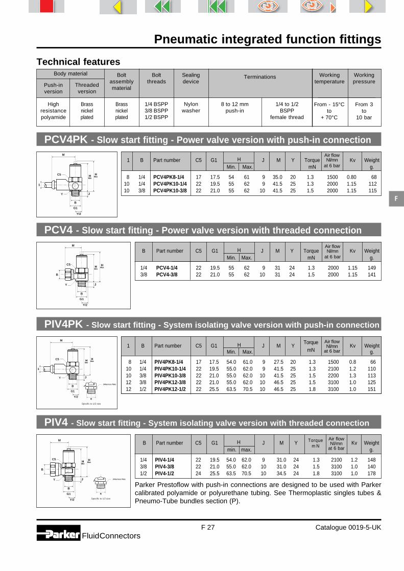
Pneumatic integrated function fittings
F 27 Catalogue 0019-5-UKFluidConnectors
F
Highresistancepolyamide
Brassnickelplated
From - 15°Cto
+ 70°C
From 3to
10 bar
Technical featuresBody material Bolt
assemblymaterial
Boltthreads
Sealingdevice
Terminations Workingtemperature
Workingpressure
Push-inversion
Threadedversion
Nylonwasher
1/4 BSPP3/8 BSPP1/2 BSPP
8 to 12 mmpush-in
Brassnickelplated
1/4 to 1/2BSPP
female thread
PCV4PK - Slow start fitting - Power valve version with push-in connection
PCV4 - Slow start fitting - Power valve version with threaded connection
PIV4PK - Slow start fitting - System isolating valve version with push-in connection
TorquemN
Air flowNl/mn
at 6 bar
PIV4 - Slow start fitting - System isolating valve version with threaded connection
Torquem N
Air flowNl/mn
at 6 bar
Parker Prestoflow with push-in connections are designed to be used with Parkercalibrated polyamide or polyurethane tubing. See Thermoplastic singles tubes &Pneumo-Tube bundles section (P).
Air flowNl/mn
at 6 bar
1
B
G1
Y/2
C5
Y J
H�Min
H�Max
M
B
B
G1
Y/2
C5
J
H�Min
H�Max
M
Y
1
B
G1
Y/2
C5
Y J
H�Min
H�Max
M
B
B
G1
Y/2
C5
J
H�Min
H�Max
M
Y
B��
Specific to 1/2 size
24/across flats
1 B Part number C5 G1 H J M Y Torque Kv WeightMin. Max. mN g.
8 1/4 PCV4PK8-1/4 17 17.5 54 61 9 35.0 20 1.3 1500 0.80 6810 1/4 PCV4PK10-1/4 22 19.5 55 62 9 41.5 25 1.3 2000 1.15 11210 3/8 PCV4PK10-3/8 22 21.0 55 62 10 41.5 25 1.5 2000 1.15 115
B��
Specific to 1/2 size
24/across flats
B Part number C5 G1 H J M Y Torque Kv WeightMin. Max. mN g.
1/4 PCV4-1/4 22 19.5 55 62 9 31 24 1.3 2000 1.15 1493/8 PCV4-3/8 22 21.0 55 62 10 31 24 1.5 2000 1.15 141
1 B Part number C5 G1 H J M Y Kv WeightMin. Max. g.
8 1/4 PIV4PK8-1/4 17 17.5 54.0 61.0 9 27.5 20 1.3 1500 0.8 6610 1/4 PIV4PK10-1/4 22 19.5 55.0 62.0 9 41.5 25 1.3 2100 1.2 11010 3/8 PIV4PK10-3/8 22 21.0 55.0 62.0 10 41.5 25 1.5 2200 1.3 11312 3/8 PIV4PK12-3/8 22 21.0 55.0 62.0 10 46.5 25 1.5 3100 1.0 12512 1/2 PIV4PK12-1/2 22 25.5 63.5 70.5 10 46.5 25 1.8 3100 1.0 151
B Part number C5 G1 H J M Y Kv Weight min. max. g.
1/4 PIV4-1/4 22 19.5 54.0 62.0 9 31.0 24 1.3 2100 1.2 1483/8 PIV4-3/8 22 21.0 55.0 62.0 10 31.0 24 1.5 3100 1.0 1401/2 PIV4-1/2 24 25.5 63.5 70.5 10 34.5 24 1.8 3100 1.0 178
Air flowNl/mn
at 6 bar

Pneumatic integrated function fittings
F 28 Catalogue 0019-5-UKFluidConnectors
F
Pressure saving Pressure saving indication
Prestoreduce - Pressure reduction fittings
PrincipleThis function fitting is manually preset to provide the cylinder with optimum air pressure. This reduces the airconsumption of the cylinder generating energy savings. This fitting is particularly suitable for cylinders used in cutting,pressing or gripping operations.
- System pressure (Pi) isreduced by a spring-loadedvalve which can be calibratedby the set screw.
- The greater the reduction bet-ween inlet and outlet pressurethe larger the energy savings.
- The coloured indicator showsthe energy savings achieved.
- The purge vent allows rapidexhaust of air in emergencies.
- Adjustment can be made withan Allen key or manual ratchetcontrol (see page F 29).
- An anti tamper plug can befitted after the pressure hasbeen set (see page F 29).
PrPrPr
Time
Pr reduced
Pressure
Pressure saving
saving
applied pressure Pr
back pressure
Pi system
start ofcylinder stroke
end ofcylinder stroke
reversal ofcontrol valve
Alignment between the level of saving shown
by the indicator and that shown by the marking
yellow : maximum saving
orange : high saving
red : moderate saving
Energysetting Pi - Pr
0
2
4
6 bar
1 - Out stroke 2 - End of stroke 3 - Return stroke
Energy saving indicator
Adjustable spring
Check valve
Rapidexhaust vent
Poppetvalve
PiPower valve
To thecylinderPr

Pneumatic integrated function fittings
F 29 Catalogue 0019-5-UKFluidConnectors
F
Technical featuresBody material Bolt
assemblymaterial
Boltthreads
Sealingdevice
Terminations Workingtemperature
Workingpressure
Banjoversion
PRB4PB - Pressure reducer - Banjo version with push-in connection
PRIPB - Pressure reducer - In-line version with push-in connection
PRI4 - Pressure reducer - In-line version with threaded connection
PRB4 - Pressure reducer - Banjo version with threaded connection
Nickelplatedbrass
Brass
1/8 BSPP1/4 BSPP3/8 BSPP1/2 BSPP
NylonWasher
6 to 10 mmPush-in
1/8 to 1/2BSPP female
thread
- 15°Cto
+ 70°C
1 barto
8 bar
Parker Prestoflow with push-in connections are designed to be used with Parkercalibrated polyamide or polyurethane tubing. See Thermoplastic singles tubes &Pneumo-Tube bundles section (P).
H
J
H1
Y
M
B
G1
G3G2
Y/2
C5
1
�
B
H
J
H1
Y
M
B
G1
G3G2
Y/2
C5
C1
M
L
TG3
G2��
WH
H1
H2
1
L1
L
TG3
G2��
WHH2
C1
C2
B
1 B Part number C5 G1 G2 G3 H H1 J M Y WeightMin. Max. g.
6 1/8 PRB4PB6-1/8 19 19.5 22 20 49 57 12 6 43 21 1356 1/4 PRB4PB6-1/4 19 19.5 22 20 49 57 12 6 43 21 1368 1/4 PRB4PB8-1/4 19 19.5 22 20 49 57 12 6 40 21 133
10 1/4 PRB4PB10-1/4 27 26.0 28 26 55 64 15 6 50 28 24110 3/8 PRB4PB10-3/8 27 26.0 28 26 55 64 15 8 50 28 250
B Part number C1 C5 G1 G2 G3 H H1 J M Y WeightMin. Max. g.
1/8 PRB4-1/8 19 19 19.5 22 20 49 57 12 6 45 21 1571/4 PRB4-1/4 19 19 19.5 22 20 49 57 12 6 45 21 1503/8 PRB4-3/8 24 27 26.0 28 26 55 64 15 6 56 28 2831/2 PRB4-1/2 30 30 30.0 32 31 75 86 23 8 63 33 525
1 Part number G2 G3 H H1 H2 L M T W WeightMin. Max. Min. Max. g.
6 PRIPB6 11 21 49 57 14 22 75 32.5 18.5 4 2088 PRIPB8 13 21 49 57 14 22 72 32.5 18.5 4 196
10 PRIPB10 17 28 61 70 19 27 90 41.5 22.5 5 405
B Part number C1 C2 G 2 G3 H H1 H2 L L1 T W WeightMin. Max. Min. Max. g.
1/8 PRI4-1/8 17 19 11 21 49 57 14 22 74 35 18.5 4 2101/4 PRI4-1/4 17 19 13 21 49 57 14 22 83 44 18.5 4 2113/8 PRI4-3/8 22 27 17 28 61 70 19 27 90 44 22.5 5 3921/2 PRI4-1/2 27 30 19 31 75 86 23 32 119 61 27.5 7 655
Metal
In lineversion

Pneumatic integrated function fittings
F 30 Catalogue 0019-5-UKFluidConnectors
F
Prestosil - Silencer and flow control valve
PrinciplePrestosil silencers are designed for mounting into the exhaust valve of single acting cylinders or on the directionalcontrol valve.
Noise reductionThe escaping air is pre-expanded in thechamber of the silencer. It then flows through asintered bronze cartridge whose design providesa complete expansion of the exhaust air.
Flow controlThe adjusting screw of the uni- direction flowcontrol valve allows fine adjustment of therestriction and thus precise control of thepiston-rod speed. The setting is secured by alock nut.
Operation
Bodymaterial
Sintermaterial
Needlevalve
material
Locknutmaterial
Silencerthread
Workingtemperature
Workingpressure
Aluminium Bronze Aluminium Aluminium1/8 BSPP1/4 BSPP3/8 BSPP1/2 BSPP
From -25°Cto
+ 100°C
From 0.1to
10 bar
Technical features
Partnumber
Working pressure
1 bar 2 bar 3 bar 4 bar 5 bar 6 bar 7 bar
PRS4-1/8PRS4-1/4PRS4-3/8PRS4-1/2
6111919
15222727
20.527.033.033.0
21293535
22323737
24323939
24324040
Noise reduction characteristicsAt an average working pressure of 5 bar the noise reduction achieved with the appropriate Prestosil model rangesfrom 22 to 37 dB.
PRS - Silencer and flow control valve
BO
L
C
B Part number C L O WeightMin. Max. g.
1/8 PRS4-1/8 11 43 48 14 451/4 PRS4-1/4 14 60 68 17 553/8 PRS4-3/8 19 80 88 26 981/2 PRS4-1/2 22 83 91 26 104
Int
egratedf i t t i n g
Sinteredbronze cartridge
Lock nut
Precision adjusting screw
Male pipe thread
Pre-expansion chamberwith exhaust slots

Pneumatic integrated function fittings
F 31 Catalogue 0019-5-UKFluidConnectors
F
For product availability please consult our price list 0093-UK.Dimensions shown may be changed at any time without prior notice.
Non-return union
Clip - Flow control clips
Ratchet 6 - manual ratchet
Suitable for use with pressure reducing fittings - PRB/PRI
Splug - Adjuster plug
PGAUGE - Plug-in pressure gauge
Suitable for in-line flow regulators PTF series
The plug in pressure gauge enables the energy savings made with Prestoreduce fittings to be measured.
H
L
F
0 10
2
4 6
8
D��
0 - 10 bar
G1
G2bar
Push
Turn
Setting secured
Tube Part number WeightOD g.
4 Clip4 36-8 Clip6-8 4
10-12 Clip10-12 9
Tube Part number L H WeightOD g.
6 RATCHET 6 22 15 39
D Part number Weightg.
8-16 SPLUG 1
D Part number G1 G2 Weightg.
6 PGAUGE 11 50 74
Accessories - Flow control
PWA-L - Non-return equal union
D
1 Part number O L Air flow Kv Weightat 6 bar NI/min g.
4 PWA-L1444 11.0 43.0 330 0.12 86 PWA-L1466 13.0 49.5 665 0.14 138 PWA-L1488 15.5 55.0 1630 0.80 18
L
1 O
NEW

MetrulokBrass fittingfor copper and plastic tubing
Catalogue 4324-UK

Metrulok fitting
G 2 Catalogue 4324-UKFluidConnectors
G
Index
male - NPTFBM - p. G 6
male - BSPPF4BM - p. G 6
Straightconnectors
male - metricF8BM - p. G 7
male - BSPTF3BM - p. G 6
unionHBM - p. G 7
female - NPTGBM - p. G 7
female - BSPPG4BM - p. G 8
90° elbows
Bulkheadconnectors
unionWBM - p. G 8
mixed unionWBMPB - p. G 8
male - NPTCBM - p. G 9
male - BSPTC3BM - p. G 9
adjustable male - metricC8BM - p. G 9
unionEBM - p. G 10
Tees
unionJBM - p. G 10
male run - NPTRBM - p. G 10
male run - BSPTR3BM - p. G 11
male branch - NPTSBM - p. G 11
male branch - BSPTS3BM - p. G 11
Cross
Banjo
unionKBM - p. G 12
single - assembledBSPPCOR4BM - p. G 12
Tube endadaptors
male - NPTT2HF - p. G 12
male - BSPTT23HF - p. G 13
male - metricT28HF - p. G 13
female - NPTT2HG - p. G 13
female - BSPPT24HG - p. G 14
Connectoraccessories
nutBM - p. G 14
nut + ferruleBTM - p. G 14
fitting body capFNM - p. G 14
tube plugPNM - p. G15
ferruleTM - p. G 15
tube end reducerTRBM - p. G 15
tube insertT23U - p. G 15

Metrulok fitting
G 3 Catalogue 4324-UKFluidConnectors
G
Principle
Metrulok is a one-piece, ready-to-use, bite type fittingwith back compression.
The ferrule is held captive in the nut.
The fitting is designed to permit tube entry and fittingmake-up without removal of the nut and ferrule,avoiding assembly of the fitting components prior touse.
Technical features
ApplicationsWith its ability to be used with manytypes of tubing and its variety ofthread forms, Metrulok is suitable fora wide range of fluid applications.
It is particularly suitable for arduousenvironments, with its wide tempe-rature range and excellent vibrationcharacteristics.
From - 60°C
to
+ 190°C
Body Nut Ferrule
Brass Brass Brass
Tube O.D.mm
bar 180 180 130 110 90 75 60
4 6 8 10 12 1416to
22
* The pressures given are with copper tubing. For polyamide or polyurethane tubing see Thermoplastic single tubes and Pneumo-Tube bundlessection (P).
1 2 3Working pressure* depending on tube O.D.
(with 1 mm wall thickness)Working
temperatureMaterial
Compressors Machine tools
Automotive
Washingequipment
Welding
Heating systems
321

Metrulok fitting
G 4 Catalogue 4324-UKFluidConnectors
G
Advantages
Fitting ready to use- Compact fully assembled fitting,
saving time at installation.- Captive snap-in ferrule.- Simplified handling and stock control.- No pre-setting of the ferrule.
Safety- Visible ferrule (extending through
rear of nut) allows quality controlchecks for correct assembly.
Excellent vibration resistance- Vibration is contained by the back
compression of the ferrule exten-ding outside the nut.
- The tube is held at the bottom ofthe fitting.The tube is thus held between twopoints so that vibration running alongthe tube does not affect the sealingand bite area.
Wide variety of tubingMetrulok can be used with coppertube conforming to DIN 1786, NFAS1-120, BS 2871 Part 2.Metrulok is suitable for use withmost types of plastic tubing (polya-mide, polyurethane, polyethylene,Pebax, Teflon®...)Parker Push-Lok hoses can alsobe connected with Metrulok bodiesusing the Push-Lok FF series con-nectors (see Push-Lok Hose andFittings section).
Forgings- Metrulok shaped fittings are pro-
duced from hot forgings to meetexacting requirements.
- The hot forging process increasesthe density of the material, refinesthe grain structure and improvesmaterial strength.
Positive sealing and bite- The wedging action of the nut
when tightened causes the ferruleto bite into the outside diameter ofthe tube wall for a leakproofconnection.
- With flexible tubing (polyurethane,PEBA or polyethylene), it is recom-mended is used a tube insert toensure positive holding of the tube.

Metrulok fitting
G 5 Catalogue 4324-UKFluidConnectors
G
Cut the tube square De-burr (copper tube)
Spanner tighten the nut (one turn,or one and half turns according tothe size)
Disassembly - remakeThe Metrulok fitting can beassembled and disassembled atleast 15 times.At each remake, hand tighten thenut, then spanner tighten 1/6 of aturn.
Assembly instructions
Fitting dimensions
1Tube O.D.
mm
2Metric
straight thread
3Inside
diameter
mm
4Hex
of nut
mm
5Tube entry
body
mm
6Tube entry
compl. fitting
mm
Spannertightening
in
turns
4 M8x1 2 10 4 12 1.1/26 M10x1 4 12 5 13 1.1/28 M12x1 6 14 6 14 1.1/2
10 M14x1 8 17 6 14 1.1/212 M16x1 10 19 7 15 1.1/2
14 M18x1 12 22 8 16 1.1/216 M22x1.5 14 27 8 16 118 M24x1.5 16 30 9 21 120 M26x1.5 18 32 9 21 122 M28x1.5 20 36 10 22 1
Insert the tube through the nutand ferrule until it bottoms
Finger tighten the nut
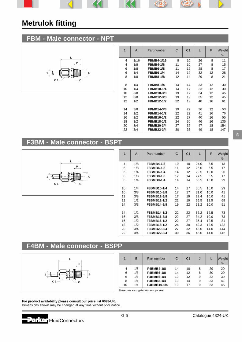
Metrulok fitting
G 6 Catalogue 4324-UKFluidConnectors
G
For product availability please consult our price list 0093-UK.Dimensions shown may be changed at any time without prior notice.
FBM - Male connector - NPT
F3BM - Male connector - BSPT
These parts are supplied with a copper seal.
C 1 C
A
L
P
1
C 1 C
A
L
P
1
C 1 C
B
L
J
1
1 A Part number C C1 L P Weightg.
4 1/16 FBMB4-1/16 8 10 26 8 114 1/8 FBMB4-1/8 11 10 27 8 156 1/8 FBMB6-1/8 11 12 28 8 176 1/4 FBMB6-1/4 14 12 32 12 288 1/8 FBMB8-1/8 12 14 29 8 21
8 1/4 FBMB8-1/4 14 14 33 12 3010 1/4 FBMB10-1/4 14 17 33 12 3010 3/8 FBMB10-3/8 19 17 34 12 4512 3/8 FBMB12-3/8 19 19 35 12 4512 1/2 FBMB12-1/2 22 19 40 16 61
14 3/8 FBMB14-3/8 19 22 36 12 5314 1/2 FBMB14-1/2 22 22 41 16 7616 1/2 FBMB16-1/2 22 27 40 16 5518 1/2 FBMB18-1/2 24 30 46 16 13520 3/4 FBMB20-3/4 27 32 47 18 15422 3/4 FBMB22-3/4 30 36 49 18 147
1 A Part number C C1 L P Weightg.
4 1/8 F3BMB4-1/8 10 10 24.0 6.5 136 1/8 F3BMB6-1/8 11 12 26.0 6.5 176 1/4 F3BMB6-1/4 14 12 29.5 10.0 268 1/8 F3BMB8-1/8 12 14 27.5 6.5 178 1/4 F3BMB8-1/4 14 14 30.5 10.0 29
10 1/4 F3BMB10-1/4 14 17 30.5 10.0 2910 3/8 F3BMB10-3/8 17 17 31.0 10.0 4112 3/8 F3BMB12-3/8 17 19 32.4 10.0 4112 1/2 F3BMB12-1/2 22 19 35.5 12.5 6814 3/8 F3BMB14-3/8 19 22 33.2 10.0 51
14 1/2 F3BMB14-1/2 22 22 36.2 12.5 7316 3/8 F3BMB16-3/8 22 27 34.2 10.0 7316 1/2 F3BMB16-1/2 22 27 36.4 12.5 8118 1/2 F3BMB18-1/2 24 30 42.3 12.5 13220 3/4 F3BMB20-3/4 27 32 43.0 14.0 14422 3/4 F3BMB22-3/4 30 36 45.0 14.0 142
1 B Part number C C1 J L Weightg.
4 1/8 F4BMB4-1/8 14 10 8 29 206 1/8 F4BMB6-1/8 14 12 8 30 296 1/4 F4BMB6-1/4 19 12 9 32 398 1/4 F4BMB8-1/4 19 14 9 33 41
10 1/4 F4BMB10-1/4 19 17 9 33 45
F4BM - Male connector - BSPP

Metrulok fitting
G 7 Catalogue 4324-UKFluidConnectors
G
For product availability please consult our price list 0093-UK.Dimensions shown may be changed at any time without prior notice.
F8BM - Male connector - metric straight thread
These parts are supplied with a copper seal.
HBM - Equal union
GBM - Female connector - NPT
C 1 C
B
L
J
1
C 1 C 1C
1
L
1
C 1
A
L
P
C
1
1 B Part number C C1 J L Weightg.
4 M5x0.8 F8BMB4M5 8 10 5 24 1012 M16x1.5 F8BMB12M16 22 19 11 37 6012 M22x1.5 F8BMB12M22 27 19 12 40 9814 M16x1.5 F8BMB14M16 22 22 11 38 6814 M22x1.5 F8BMB14M22 27 22 12 41 102
16 M16x1.5 F8BMB16M16 22 27 11 37 8416 M22x1.5 F8BMB16M22 27 27 12 40 112
1 Part number C C1 L Weightg.
4 HBMB4 8 10 31 156 HBMB6 10 12 34 228 HBMB8 12 14 37 31
10 HBMB10 14 17 37 4012 HBMB12 17 19 39 50
14 HBMB14 19 22 41 7416 HBMB16 22 27 41 10918 HBMB18 24 30 51 20220 HBMB20 27 32 51 20222 HBMB22 30 36 54 182
1 A Part number C C1 L P Weightg.
6 1/8 GBMB6-1/8 14 12 29 10 236 1/4 GBMB6-1/4 19 12 32 13 388 1/8 GBMB8-1/8 14 14 30 10 278 1/4 GBMB8-1/4 19 14 33 13 44
10 1/4 GBMB10-1/4 19 17 33 13 44
10 3/8 GBMB10-3/8 22 17 35 15 5812 3/8 GBMB12-3/8 22 19 36 15 6012 1/2 GBMB12-1/2 27 19 38 16 8414 3/8 GBMB14-3/8 22 22 37 15 7114 1/2 GBMB14-1/2 27 22 39 16 9716 1/2 GBMB16-1/2 27 27 39 16 110

Metrulok fitting
G 8 Catalogue 4324-UKFluidConnectors
G
For product availability please consult our price list 0093-UK.Dimensions shown may be changed at any time without prior notice.
G4BM - Female connector - BSPP
WBM - Bulkhead union
WBMPB - Mixed bulkhead equal union
This bulkhead fitting combines a Prestolok and Metrulok connection to connect a copper tube with a plastic tube.For this conversion fitting please consult Prestolok section(D), for recommended working pressure and temperature.
C 1
B
L
J
C
1
2
L
WL1
C 1 C 4O C 2
1
B
C 1 C 1C C 4
L
L2L1
W
B
11
1 B Part number C C1 J L Weightg.
4 1/8 G4BMB4-1/8 14 10 8 26 196 1/8 G4BMB6-1/8 14 12 8 27 226 1/4 G4BMB6-1/4 19 12 10 29 358 1/8 G4BMB8-1/8 14 14 8 28 258 1/4 G4BMB8-1/4 19 14 10 30 39
10 1/4 G4BMB10-1/4 19 17 10 30 4110 3/8 G4BMB10-3/8 22 17 12 32 5212 3/8 G4BMB12-3/8 22 19 12 33 5412 1/2 G4BMB12-1/2 27 19 14 36 8214 3/8 G4BMB14-3/8 22 22 12 34 63
14 1/2 G4BMB14-1/2 27 22 14 37 9216 1/2 G4BMB16-1/2 27 27 14 37 10518 1/2 G4BMB18-1/2 27 30 14 41 148
1 Part number B C C1 C4 L L1 L2 W WeightMax. g.
4 WBMB4 M8x1 12 10 10 47 19 28 10 306 WBMB6 M10x1 14 12 12 49 20 29 10 368 WBMB8 M12x1 16 14 14 52 21 31 10 48
10 WBMB10 M14x1 19 17 17 53 22 31 10 6512 WBMB12 M16x1 22 19 19 56 24 32 10 85
14 WBMB14 M18x1 24 22 22 60 26 34 10 11216 WBMB16 M22x1.5 27 27 24 58 25 33 10 22518 WBMB18 M24x1.5 30 30 27 70 31 39 10 27520 WBMB20 M26x1.5 32 32 32 70 31 39 10 28022 WBMB22 M28x1.5 36 36 36 74 33 41 10 262
1 2 B Part number C1 C2 C4 L L1 O W WeightMax. g.
4 4 M8x1 WBMPB4 10 10 12 34 15 8.5 5 226 6 M10x1 WBMPB6 12 10 12 37 16 10.5 5 228 8 M12x1 WBMPB8 14 14 16 39 17 12.5 5 29
10 10 M14x1 WBMPB10 17 17 19 45 20 14.5 5 5012 12 M16x1 WBMPB12 22 19 22 49 21 16.5 5 8514 14 M18x1 WBMPB14 24 22 22 52 23 18.5 7 112

Metrulok fitting
G 9 Catalogue 4324-UKFluidConnectors
G
For product availability please consult our price list 0093-UK.Dimensions shown may be changed at any time without prior notice.
CBM - 90° male elbow - NPT
C3BM - 90° male elbow - BSPT
C8BM - 90° adjustable male elbow - metric straight thread
These fittings are equiped with Nitrile O-Ring. The temperature range for this fitting range is from -25° C to+ 100° C.
1
C 1
Y
M
A
NP
1
C 1
Y
M
A
NP
1
C 1
Y
M
N
JC 4
B
1 A Part number C1 M N P Y Weightg.
4 1/8 CBMB4-1/8 10 22 17 8 7 176 1/8 CBMB6-1/8 12 24 18 8 8 226 1/4 CBMB6-1/4 12 24 22 12 8 308 1/8 CBMB8-1/8 14 26 19 8 10 288 1/4 CBMB8-1/4 14 26 23 12 10 36
10 1/4 CBMB10-1/4 17 27 24 12 12 4910 3/8 CBMB10-3/8 17 28 25 12 12 5512 3/8 CBMB12-3/8 19 32 27 12 14 5112 1/2 CBMB12-1/2 19 32 31 16 14 7014 3/8 CBMB14-3/8 22 32 26 12 16 87
14 1/2 CBMB14-1/2 22 33 31 16 16 9416 1/2 CBMB16-1/2 27 35 34 16 16 11118 1/2 CBMB18-1/2 30 41 35 16 20 16320 3/4 CBMB20-3/4 32 45 40 18 24 21522 3/4 CBMB22-3/4 36 46 40 18 24 191
1 A Part number C1 M N P Y Weightg.
4 1/8 C3BMB4-1/8 10 22 17.0 8.0 7 166 1/8 C3BMB6-1/8 12 24 17.0 6.5 8 216 1/4 C3BMB6-1/4 12 24 20.5 10.0 8 308 1/8 C3BMB8-1/8 14 26 18.0 6.5 10 288 1/4 C3BMB8-1/4 14 26 21.5 10.0 10 35
10 1/4 C3BMB10-1/4 17 27 22.5 10.0 12 4910 3/8 C3BMB10-3/8 17 28 22.1 10.0 12 5212 3/8 C3BMB12-3/8 19 32 25.1 10.0 14 5112 1/2 C3BMB12-1/2 19 32 27.8 12.5 14 6414 3/8 C3BMB14-3/8 22 32 24.1 10.0 16 67
14 1/2 C3BMB14-1/2 22 32 27.3 12.5 16 9216 1/2 C3BMB16-1/2 27 35 30.8 12.5 18 10818 1/2 C3BMB18-1/2 30 41 31.8 12.5 20 16420 3/4 C3BMB20-3/4 32 45 36.5 14.0 24 20522 3/4 C3BMB22-3/4 36 46 36.5 14.0 24 186
1 B Part number C1 C4 J M N Y Weightg.
12 M16x1.5 C8BMB12M16 19 22 9 32 35 14 7312 M22x1.5 C8BMB12M22 19 30 10 35 39 20 15314 M16x1.5 C8BMB14M16 22 22 9 32 33 16 10314 M22x1.5 C8BMB14M22 22 30 10 35 39 20 16016 M16x1.5 C8BMB16M16 24 22 9 35 36 18 12816 M22x1.5 C8BMB16M22 27 30 10 36 39 20 169

Metrulok fitting
G 10 Catalogue 4324-UKFluidConnectors
G
For product availability please consult our price list 0093-UK.Dimensions shown may be changed at any time without prior notice.
EBM - 90° union elbow
JBM - Union tee
RBM - Male run tee - NPT
1
C 1
Y
M
1
1
C 1Y
L
M
1
1
1
C 1
Y
L
M NP
1
A
1 Part number C1 M Y Weightg.
4 EBMB4 10 22 7 206 EBMB6 12 24 8 288 EBMB8 14 26 10 39
10 EBMB10 17 27 12 6012 EBMB12 19 32 14 60
14 EBMB14 22 32 16 8716 EBMB16 27 35 18 19518 EBMB18 30 41 20 23020 EBMB20 32 45 24 27022 EBMB22 36 46 24 222
1 Part number C1 L M Y Weightg.
4 JBMB4 10 47 23.5 7 336 JBMB6 12 48 24.0 8 408 JBMB8 14 52 26.0 10 54
10 JBMB10 17 54 27.0 12 6912 JBMB12 19 63 31.5 14 93
14 JBMB14 22 63 31.5 16 12816 JBMB16 27 69 34.5 18 18018 JBMB18 30 82 41.0 20 33620 JBMB20 32 89 44.5 24 37922 JBMB22 36 91 45.5 24 309
1 A Part number C1 L M N P Y Weightg.
6 1/8 RBMB6-1/8 12 42 24 18 8 8 336 1/4 RBMB6-1/4 12 48 25 23 12 10 318 1/8 RBMB8-1/8 14 45 26 19 8 10 238 1/4 RBMB8-1/4 14 49 26 23 12 10 32
10 1/4 RBMB10-1/4 17 51 27 24 12 12 97
10 3/8 RBMB10-3/8 17 52 28 24 12 12 3912 3/8 RBMB12-3/8 19 59 32 27 12 14 5112 1/2 RBMB12-1/2 19 63 32 31 16 14 7114 3/8 RBMB14-3/8 22 60 33 28 12 16 6014 1/2 RBMB14-1/2 22 64 33 31 16 16 7616 1/2 RBMB16-1/2 27 69 35 34 16 18 83

Metrulok fitting
G 11 Catalogue 4324-UKFluidConnectors
G
For product availability please consult our price list 0093-UK.Dimensions shown may be changed at any time without prior notice.
R3BM - Male run tee - BSPT
SBM - Male branch tee - NPT
S3BM - Male branch tee - BSPT
1
C 1Y
L
M
1
A
NP
1
C 1Y
L
M
1
A
NP
1
C 1
Y
L
M NP
1
A
1 A Part number C1 L M N P Y Weightg.
6 1/8 S3BMB6-1/8 12 48 24.0 17.0 6.5 8 336 1/4 S3BMB6-1/4 12 49 24.5 20.5 10.0 10 448 1/8 S3BMB8-1/8 14 52 26.0 18.0 6.5 10 558 1/4 S3BMB8-1/4 14 52 26.0 21.5 10.0 10 50
10 1/4 S3BMB10-1/4 17 54 27.0 22.5 10.0 12 59
10 3/8 S3BMB10-3/8 17 56 28.0 22.1 10.0 12 6512 3/8 S3BMB12-3/8 19 63 31.5 25.1 10.0 14 8112 1/2 S3BMB12-1/2 19 63 31.5 27.8 12.5 14 9114 3/8 S3BMB14-3/8 22 63 31.5 24.1 10.0 16 10914 1/2 S3BMB14-1/2 22 65 32.5 27.3 12.5 16 12316 1/2 S3BMB16-1/2 27 69 34.5 30.8 12.5 18 155
1 A Part number C1 L M N P Y Weightg.
6 1/8 SBMB6-1/8 12 48 24.0 18 8 8 336 1/4 SBMB6-1/4 12 50 25.0 23 12 10 318 1/8 SBMB8-1/8 14 52 26.0 19 8 10 238 1/4 SBMB8-1/4 14 52 26.0 23 12 10 32
10 1/4 SBMB10-1/4 17 56 28.0 24 12 12 97
10 3/8 SBMB10-3/8 17 56 28.0 24 12 12 3912 3/8 SBMB12-3/8 19 63 31.5 25 12 14 5112 1/2 SBMB12-1/2 19 63 31.5 31 16 14 7114 3/8 SBMB14-3/8 22 63 31.5 28 12 16 6014 1/2 SBMB14-1/2 22 65 32.5 31 16 16 7616 1/2 SBMB16-1/2 27 69 34.5 34 16 18 83
1 A Part number C1 L M N P Y Weightg.
6 1/8 R3BMB6-1/8 12 42 24 17.0 6.5 8 336 1/4 R3BMB6-1/4 12 48 25 20.5 10.0 10 458 1/8 R3BMB8-1/8 14 45 26 18.0 6.5 10 438 1/4 R3BMB8-1/4 14 49 26 21.5 10.0 10 52
10 1/4 R3BMB10-1/4 17 51 27 22.5 10.0 12 60
10 3/8 R3BMB10-3/8 17 52 28 22.1 10.0 12 6512 3/8 R3BMB12-3/8 19 59 32 25.1 10.0 14 8112 1/2 R3BMB12-1/2 19 63 32 27.8 12.5 14 10114 3/8 R3BMB14-3/8 22 59 32 24.1 10.0 16 11014 1/2 R3BMB14-1/2 22 63 33 27.3 12.5 16 12616 1/2 R3BMB16-1/2 27 69 35 30.8 12.5 18 151

Metrulok fitting
G 12 Catalogue 4324-UKFluidConnectors
G
For product availability please consult our price list 0093-UK.Dimensions shown may be changed at any time without prior notice.
COR4BM - Single banjo BSPP
These parts are supplied with peripheral seals.
T2HF - Tube end male adaptor - NPT
KBM - Union cross
B
C 1
M
N 1
JN
C 5
1
1
C 1Y
L
M
1
1
C
A
L
P
1
1 Part number C1 L M Y Weightg.
6 KBMB6 12 48 24.0 8 508 KBMB8 14 52 26.0 10 69
10 KBMB10 17 54 27.0 12 9312 KBMB12 19 63 31.5 14 12214 KBMB14 22 65 32.5 16 18416 KBMB16 27 69 34.5 18 236
1 B Part number C1 C5 J M N N1 Weightg.
4 1/8 COR4BMB4-1/8 10 14 6 23 15 27 456 1/4 COR4BMB6-1/4 12 19 9 26 18 29 678 1/4 COR4BMB8-1/4 14 19 9 27 20 35 83
14 1/2 COR4BMB14-1/2 22 27 12 34 27 48 22016 1/2 COR4BMB16-1/2 27 27 12 33 27 48 316
18 1/2 COR4BMB18-1/2 30 27 12 38 29 54 30320 3/4 COR4BMB20-3/4 32 32 14 41 33 60 44922 3/4 COR4BMB22-3/4 36 32 14 43 38 70 519
1 A Part number C L P Weightg.
6 1/8 T2HFB6-1/8 11 31 8 106 1/4 T2HFB6-1/4 14 36 12 218 1/8 T2HFB8-1/8 11 32 8 98 1/4 T2HFB8-1/4 14 36 12 19
10 1/4 T2HFB10-1/4 14 37 12 21
10 3/8 T2HFB10-3/8 19 38 12 3512 3/8 T2HFB12-3/8 19 38 12 2912 1/2 T2HFB12-1/2 22 43 16 5514 3/8 T2HFB14-3/8 19 39 12 3114 1/2 T2HFB14-1/2 22 44 16 50
16 1/2 T2HFB16-1/2 22 46 16 4418 1/2 T2HFB18-1/2 22 50 16 5520 3/4 T2HFB20-3/4 27 51 18 8022 3/4 T2HFB22-3/4 27 54 18 85

Metrulok fitting
G 13 Catalogue 4324-UKFluidConnectors
G
For product availability please consult our price list 0093-UK.Dimensions shown may be changed at any time without prior notice.
T28HF - Tube end male adaptor - metric straight thread
T2HG - Tube end female adaptor - NPT
T23HF - Tube end male adaptor - BSPT
C
B
L
J
1
C
A
L
P
1
A
L
P
C
1
1 A Part number C L P Weightg.
6 1/8 T23HFB6-1/8 10 28.5 6.5 96 1/4 T23HFB6-1/4 14 32.5 10.0 208 1/8 T23HFB8-1/8 10 29.0 6.5 98 1/4 T23HFB8-1/4 14 33.0 10.0 17
10 1/4 T23HFB10-1/4 14 34.0 10.0 20
10 3/8 T23HFB10-3/8 17 34.1 10.0 3012 3/8 T23HFB12-3/8 17 34.6 10.0 2312 1/2 T23HFB12-1/2 22 35.1 12.5 4914 3/8 T23HFB14-3/8 17 35.6 10.0 2714 1/2 T23HFB14-1/2 22 40.1 12.5 45
16 1/2 T23HFB16-1/2 22 41.6 12.5 3918 1/2 T23HFB18-1/2 22 45.6 12.5 5220 3/4 T23HFB20-3/4 27 46.5 14.0 7822 3/4 T23HFB22-3/4 27 49.0 14.0 83
1 B Part number C J L Weightg.
12 M14x1.5 T28HFB12M14 19 10 39 3112 M16x1.5 T28HFB12M16 22 11 40 4112 M18x1.5 T28HFB12M18 24 11 40 8912 M22x1.5 T28HFB12M22 27 12 43 11314 M16x1.5 T28HFB14M16 22 11 41 42
14 M22x1.5 T28HFB14M22 27 12 44 11516 M16x1.5 T28HFB16M16 22 11 43 7516 M18x1.5 T28HFB16M18 24 11 43 9816 M22x1.5 T28HFB16M22 27 12 46 72
1 A Part number C L P Weightg.
6 1/8 T2HGB6-1/8 14 32 10 166 1/4 T2HGB6-1/4 19 35 13 338 1/8 T2HGB8-1/8 14 33 10 168 1/4 T2HGB8-1/4 19 36 13 34
10 1/4 T2HGB10-1/4 19 37 13 36
10 1/2 T2HGB10-1/2 27 41 16 6010 3/8 T2HGB10-3/8 22 39 15 4712 3/8 T2HGB12-3/8 22 39 15 4512 1/2 T2HGB12-1/2 27 41 16 7114 3/8 T2HGB14-3/8 22 40 15 44
14 1/2 T2HGB14-1/2 27 42 16 7116 1/2 T2HGB16-1/2 27 44 16 7318 1/2 T2HGB18-1/2 27 48 16 7220 3/4 T2HGB20-3/4 32 49 18 10722 3/4 T2HGB22-3/4 32 51 18 98

Metrulok fitting
G 14 Catalogue 4324-UKFluidConnectors
G
For product availability please consult our price list 0093-UK.Dimensions shown may be changed at any time without prior notice.
BM - Nut
BTM - Nut + ferrule
FNM - Fitting body cap
T24HG - Tube end female adaptor - BSPP
C 1
L
C 1
L
C 1
L
B
L
J
C
1
Tube Part number C1 L Weight g.
4 BTMB4 10 12 56 BTMB6 12 13 78 BTMB8 14 14 10
10 BTMB10 17 14 1312 BTMB12 19 15 15
14 BTMB14 22 16 2516 BTMB16 27 16 3418 BTMB18 30 21 7720 BTMB20 32 21 7322 BTMB22 36 22 55
Tube Part number C1 L Weight g.
4 BMB4 10 11 46 BMB6 12 12 68 BMB8 14 13 8
10 BMB10 17 13 1112 BMB12 19 14 13
14 BMB14 22 15 2216 BMB16 27 15 3118 BMB18 30 19 7020 BMB20 32 19 6522 BMB22 36 20 46
Tube Part number C1 L Weight g.
4 FNMB4 10 12 66 FNMB6 12 13 98 FNMB8 14 14 13
10 FNMB10 17 14 1712 FNMB12 19 15 2114 FNMB14 22 16 3416 FNMB16 27 16 8218 FNMB18 30 21 9620 FNMB20 32 21 9422 FNMB22 36 22 85
1 B Codice C J L Pesog.
6 1/8 T24HGB6-1/8 14 8 30 166 1/4 T24HGB6-1/4 19 10 32 288 1/8 T24HGB8-1/8 14 8 31 158 1/4 T24HGB8-1/4 19 10 33 28
10 1/4 T24HGB10-1/4 19 10 34 32
10 3/8 T24HGB10-3/8 22 12 36 4012 3/8 T24HGB12-3/8 22 12 36 3812 1/2 T24HGB12-1/2 27 14 40 6814 3/8 T24HGB14-3/8 22 12 37 3914 1/2 T24HGB14-1/2 27 14 41 80
16 1/2 T24HGB16-1/2 27 14 42 6718 1/2 T24HGB18-1/2 27 14 46 7920 3/4 T24HGB20-3/4 32 16 47 9522 3/4 T24HGB22-3/4 32 16 49 106

Metrulok fitting
G 15 Catalogue 4324-UKFluidConnectors
G
TM - Ferrule
TRBM - Tube end reducer
With plastic tubing, except polyamide 11 or 12, we recommend the use of a tubeinsert for positive holding of the tube. Tube inserts are available for alternative
PNM - Tube plug
Composed of : a reduction cone, a special nut and a standard ferrule.
T23U - Tube insert
L
C 1
L
1 2
C
L
J
L
R
A CB
Tube Part number C J L Weightg.
4 PNMB4 8 7 11 46 PNMB6 10 8 13 68 PNMB8 12 9 15 9
10 PNMB10 14 9 15 1112 PNMB12 17 10 16 16
14 PNMB14 19 11 17 2016 PNMB16 22 11 18 3218 PNMB18 24 12 20 4420 PNMB20 27 12 20 5022 PNMB22 30 13 22 69
Tube Part number L Weightg.
4 TMB4A 10 16 TMB6A 10 18 TMB8A 10 2
10 TMB10A 10 212 TMB12A 10 2
14 TMB14A 10 316 TMB16A 10 318 TMB18A 14 720 TMB20A 14 822 TMB22A 14 9
1 2 Part number C1 L Weightg.
6 4 TRBMB6-4 12 14 98 4 TRBMB8-4 14 15 138 6 TRBMB8-6 14 15 11
10 6 TRBMB10-6 17 16 2010 8 TRBMB10-8 17 16 19
12 8 TRBMB12-8 19 16 2512 10 TRBMB12-10 19 16 2214 10 TRBMB14-10 22 18 3514 12 TRBMB14-12 22 18 3216 12 TRBMB16-12 27 19 36
16 14 TRBMB16-14 27 19 3318 14 TRBMB18-14 30 21 4820 16 TRBMB20-16 32 21 5722 18 TRBMB22-18 36 21 84
Tube Part number A B C L R Weight±0.50 Maxi g.
4/6 T23UB4 3.2 4.0 5.0 10 0.6 16/8 T23UB6 4.8 6.0 7.9 15 0.6 1
8/10 T23UB8 7.0 8.0 10.0 15 1.0 210/12 T23UB10 9.0 10.0 12.0 15 1.0 212/14 T23UB12 11.0 12.0 14.8 15 1.0 4

PLNickel plated brass fittingfor plastic tubing
Catalogue 0017-UK

PL fitting
H 2 Catalogue 0017-UKFluidConnectors
H

PL fitting
H 3 Catalogue 0017-UKFluidConnectors
H
unionJBPL - p. H 9
Index
male - NPTFBPL - p. H 6
male - BSPPF4BPL - p. H 7
Straightconnectors
male - metricF8BPL - p. H 7
male - BSPTF3BPL - p. H 6
unionHBPL - p. H 7
Bulkheadconnectors
unionWBPL - p. H 7
90° elbows
male - NPTCBPL - p. H 8
male - BSPTC3BPL - p. H 8
male - BSPPC4BPL - p. H 8
male - metricC8BPL - p. H 9
Tees
male run - NPTRBPL - p. H 9
male run - BSPTR3BPL - p. H 9
male branch - NPTSBPL - p. H 10
male branch - BSPTS3BPL - p. H 10
Banjo
single / assembledBSPPCOR4BPL - p. H 11
Nut
nutBPLM - p. H 11

PL fitting
H 4 Catalogue 0017-UKFluidConnectors
H
Principle
PL is a two piece nickel platedbrass fitting specifically designedfor flexible tubing such as polyamide,polyurethane, PEBA, polyethylene,PTFE, PVC, etc.
The seal is obtained by the beadformed at the tube end when the nutis tightened to the fitting body.
The connection is leakproof to theburst pressure of the tube.
PL fittings can be assembled anddisassembled repeatedly.
Technical features
Workingpressure*
Workingtemperature
Nickel platedbrass
From 0.01to
40 bar
From - 40°Cto
+ 100° C
ApplicationsThe PL fitting's unique sealing methodmake it ideally suited for use with awide variety of media.
It is particularly suitable for use in fluidhandling applications wheremedia or temperature considerationslimit the method of sealing.
NutBody
* The pressures given are with polyamide tubing. For other tubing please consult us.
Nickel platedbrass
1 2
1Material
2
Laboratoryequipment
Machine toolsPackaging
Chemical industry
Welding Food industry

PL fitting
H 5 Catalogue 0017-UKFluidConnectors
H
Advantages
Maximum tensile pull out force ofpolyamide 11 tube from a PL fitting
Tube Tensile forceI.D./O.D. daN
mm
2.7/4 114/6 416/8 527.5/10 888/10 6710/12 7911/14 149
Tube nut design- Compact for fast and safe assembly- Knurled nut facilitates finger
tightening.- A positive stop prevents over-
tightening.
Rapid assemblyPL fittings can be assembled fingertight when used with soft tubing e.g.polyurethane, polyethylene, etc.This facilitates rapid assembly anddisassembly.
Excellent pull out resistanceThe clamping of the tube between thespigot of the PL fitting body and thetube nut creates an effective seal witha high pull out performance. This isparticularly useful in severe operatingconditions.The chart above indicates the avera-ge pull out values for polyamidetubing when used with a PL fitting.
Assembly instructions
Cut the tube square Push the tube over the spigot of thefitting until it comes into contact withthe stop
Insert the tube through the nut
Finger tighten the nut to the endstop when using soft tubing.
Tighten the nut with a spanner tothe end stop when using semi-rigidtubing.

PL fitting
H 6 Catalogue 0017-UKFluidConnectors
H
For product availability please consult our price list 0093-UK.Dimensions shown may be changed at any time without prior notice.
FBPL - Male connector - NPT
1 A Part number C C1 L P Weightg.
2.7/4 1/8 FBPL2.7/4-1/8 11 8 22 8 114/6 1/8 FBPL4/6-1/8 11 11 25 8 164/6 1/4 FBPL4/6-1/4 14 11 29 12 266/8 1/8 FBPL6/8-1/8 12 13 25 8 166/8 1/4 FBPL6/8-1/4 14 13 29 12 23
8/10 1/4 FBPL8/10-1/4 14 16 30 12 318/10 3/8 FBPL8/10-3/8 19 16 31 12 40
10/12 3/8 FBPL10/12-3/8 19 17 33 12 40
Fitting dimensions
1Tube
I.D./O.D.mm
2Metric
pipe thread
3Inside
diametermm
4Hex
of nutmm
5Tubeentrymm
2.7/4 M6x0.75 1.5 8 4.54/6 M9x0.75 3.0 11 6.56/8 M11x0.75 5.0 13 6.57.5/10 M13x1 6.5 17 7.08/10 M13x1 6.5 17 7.0
10/12 M15x1.25 9.0 17 7.511/14 M18x1.50 9.5 22 8.5
F3BPL - Male connector - BSPT
1 A Part number C C1 L P Weightg.
2.7/4 1/8 F3BPL2.7/4-1/8 10 8 20.5 6.5 94/6 1/8 F3BPL4/6-1/8 10 11 23.5 6.5 164/6 1/4 F3BPL4/6-1/4 14 11 26.5 10.0 256/8 1/8 F3BPL6/8-1/8 12 13 23.5 6.5 156/8 1/4 F3BPL6/8-1/4 14 13 26.5 10.0 23
6/8 3/8 F3BPL6/8-3/8 17 13 27.6 10.0 267.5/10 1/4 F3BPL7.5/10-1/4 14 16 27.5 10.0 317.5/10 3/8 F3BPL7.5/10-3/8 17 16 28.6 10.0 37
8/10 1/4 F3BPL8/10-1/4 14 16 27.5 10.0 318/10 3/8 F3BPL8/10-3/8 17 16 28.6 10.0 43
10/12 3/8 F3BPL10/12-3/8 17 17 30.1 10.0 3611/14 3/8 F3BPL11/14-3/8 19 22 32.5 10.0 58
CC 1
L
P
A1
CC 1
L
P
A1
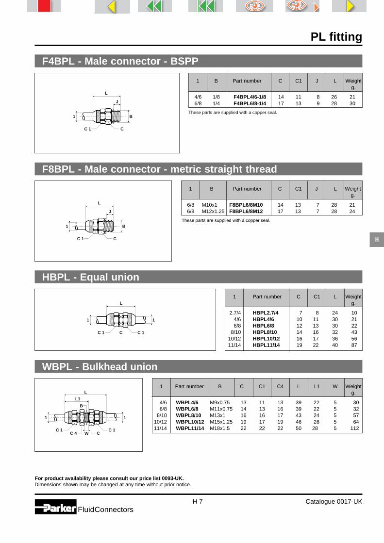
PL fitting
H 7 Catalogue 0017-UKFluidConnectors
H
1 B Part number C C1 J L Weightg.
6/8 M10x1 F8BPL6/8M10 14 13 7 28 216/8 M12x1.25 F8BPL6/8M12 17 13 7 28 24
For product availability please consult our price list 0093-UK.Dimensions shown may be changed at any time without prior notice.
F4BPL - Male connector - BSPP
1 B Part number C C1 J L Weightg.
4/6 1/8 F4BPL4/6-1/8 14 11 8 26 216/8 1/4 F4BPL6/8-1/4 17 13 9 28 30
These parts are supplied with a copper seal.
F8BPL - Male connector - metric straight thread
These parts are supplied with a copper seal.
1 Part number C C1 L Weightg.
2.7/4 HBPL2.7/4 7 8 24 104/6 HBPL4/6 10 11 30 216/8 HBPL6/8 12 13 30 22
8/10 HBPL8/10 14 16 32 4310/12 HBPL10/12 16 17 36 5611/14 HBPL11/14 19 22 40 87
HBPL - Equal union
1 Part number B C C1 C4 L L1 W Weightg.
4/6 WBPL4/6 M9x0.75 13 11 13 39 122 5 306/8 WBPL6/8 M11x0.75 14 13 16 39 122 5 32
8/10 WBPL8/10 M13x1 16 16 17 43 124 5 5710/12 WBPL10/12 M15x1.25 19 17 19 46 126 5 6411/14 WBPL11/14 M18x1.5 22 22 22 50 28 5 112
WBPL - Bulkhead union
CC 1
L
J
B1
CC 1
L
J
B1
L
C 1 CC 1
1 1
C 1 C
B
C 1 C 4
L
L1
W
1 1
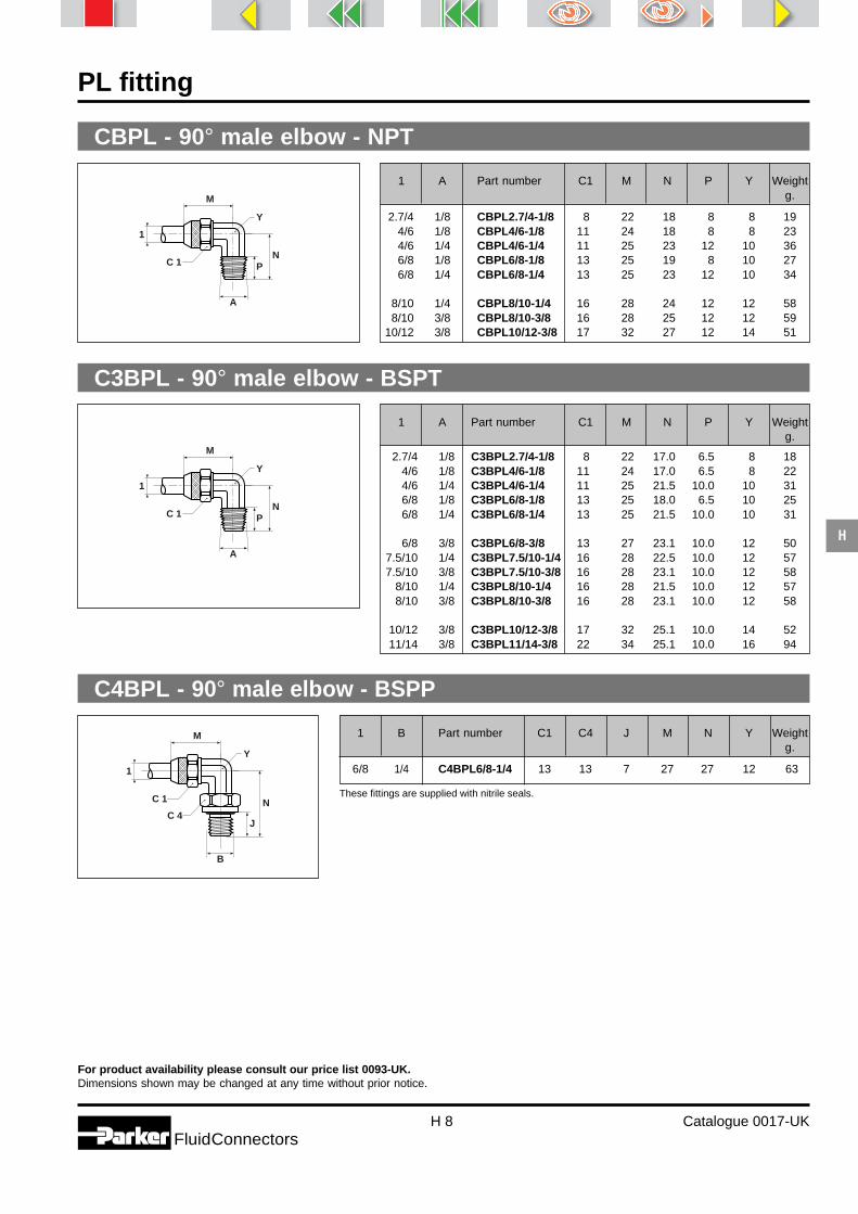
PL fitting
H 8 Catalogue 0017-UKFluidConnectors
H
For product availability please consult our price list 0093-UK.Dimensions shown may be changed at any time without prior notice.
CBPL - 90° male elbow - NPT
1 A Part number C1 M N P Y Weightg.
2.7/4 1/8 CBPL2.7/4-1/8 8 22 18 8 8 194/6 1/8 CBPL4/6-1/8 11 24 18 8 8 234/6 1/4 CBPL4/6-1/4 11 25 23 12 10 366/8 1/8 CBPL6/8-1/8 13 25 19 8 10 276/8 1/4 CBPL6/8-1/4 13 25 23 12 10 34
8/10 1/4 CBPL8/10-1/4 16 28 24 12 12 588/10 3/8 CBPL8/10-3/8 16 28 25 12 12 59
10/12 3/8 CBPL10/12-3/8 17 32 27 12 14 51
C3BPL - 90° male elbow - BSPT
1 A Part number C1 M N P Y Weightg.
2.7/4 1/8 C3BPL2.7/4-1/8 8 22 17.0 6.5 8 184/6 1/8 C3BPL4/6-1/8 11 24 17.0 6.5 8 224/6 1/4 C3BPL4/6-1/4 11 25 21.5 10.0 10 316/8 1/8 C3BPL6/8-1/8 13 25 18.0 6.5 10 256/8 1/4 C3BPL6/8-1/4 13 25 21.5 10.0 10 31
6/8 3/8 C3BPL6/8-3/8 13 27 23.1 10.0 12 507.5/10 1/4 C3BPL7.5/10-1/4 16 28 22.5 10.0 12 577.5/10 3/8 C3BPL7.5/10-3/8 16 28 23.1 10.0 12 58
8/10 1/4 C3BPL8/10-1/4 16 28 21.5 10.0 12 578/10 3/8 C3BPL8/10-3/8 16 28 23.1 10.0 12 58
10/12 3/8 C3BPL10/12-3/8 17 32 25.1 10.0 14 5211/14 3/8 C3BPL11/14-3/8 22 34 25.1 10.0 16 94
1 B Part number C1 C4 J M N Y Weightg.
6/8 1/4 C4BPL6/8-1/4 13 13 7 27 127 12 63
C4BPL - 90° male elbow - BSPP
These fittings are supplied with nitrile seals.
NPC 1
Y
M
A
1
NPC 1
Y
M
A
1
N
J
C 1
Y
C 4
M
B
1

PL fitting
H 9 Catalogue 0017-UKFluidConnectors
H
For product availability please consult our price list 0093-UK.Dimensions shown may be changed at any time without prior notice.
1 B Part number C1 C4 J M N Y Weightg.
6/8 M10x1 C8BPL6/8M10 13 13 7 22 122 10 316/8 M12x1 C8BPL6/8M12 13 13 7 25 126 12 59
C8BPL - 90° male elbow - metric straight thread
These fittings are supplied with nitrile seals.
1 Part number C1 L M Y Weightg.
2.7/4 JBPL2.7/4 8 44 22 8 244/6 JBPL4/6 11 48 24 8 426/8 JBPL6/8 13 50 25 10 45
7.5/10 JBPL7.5/10 16 56 28 12 868/10 JBPL8/10 16 56 28 12 85
10/12 JBPL10/12 17 64 32 14 10011/14 JBPL11/14 22 68 34 16 168
JBPL - Union tee
1 A Part number C1 L M N P Y Weightg.
4/6 1/8 RBPL4/6-1/8 11 42 24 18 8 8 374/6 1/4 RBPL4/6-1/4 11 48 25 23 12 10 506/8 1/4 RBLP6/8-1/4 13 48 25 23 12 10 46
RBPL - Male run tee - NPT
1 A Part number C1 L M N P Y Weightg.
4/6 1/8 R3BPL4/6-1/8 11 42 24 17.0 6.5 8 354/6 1/4 R3BPL4/6-1/4 11 48 25 21.5 10.0 10 486/8 1/8 R3BPL6/8-1/8 13 44 25 18.0 6.5 10 376/8 1/4 R3BLP6/8-1/4 13 48 25 21.5 10.0 10 45
R3BPL - Male run tee - BSPT
N
J
C 1
Y
C 4
M
B
1
1
1
C 1
Y
L
M
1
A
1
C 1
Y
L
M N
P
1
A
1
C 1
Y
L
M N
P
1

PL fitting
H 10 Catalogue 0017-UKFluidConnectors
H
For product availability please consult our price list 0093-UK.Dimensions shown may be changed at any time without prior notice.
1 A Part number C1 L M N P Y Weightg.
4/6 1/8 S3BPL4/6-1/8 11 48 24 17.0 6.5 8 354/6 1/4 S3BPL4/6-1/4 11 50 25 21.5 10.0 10 476/8 1/8 S3BPL6/8-1/8 13 50 25 18.0 6.5 10 386/8 1/4 S3BLP6/8-1/4 13 50 25 21.5 10.0 10 45
S3BPL - Male branch tee - BSPT
1 A Part number C1 L M N P Y Weightg.
4/6 1/8 SBPL4/6-1/8 11 48 24 18 18 8 354/6 1/4 SBPL4/6-1/4 11 50 25 23 112 10 506/8 1/4 SBPL6/8-1/4 13 50 25 23 112 10 49
SBPL - Male branch tee - NPT
1
C 1
Y
L
M
NP
A
1
1
C 1
Y
L
M
NP
A
1
1 B Part number C1 C5 J M N N1 Weightg.
4/6 1/8 COR4BPL4/6-1/8 11 14 7 24 16 27 684/6 1/4 COR4BPL4/6-1/4 11 19 8 26 17 29 966/8 1/8 COR4BPL6/8-1/8 13 14 7 25 16 27 686/8 1/4 COR4BLP6/8-1/4 13 19 8 27 17 30 96
COR4BPL - Single banjo - BSPP
1 Part number C1 L Weight g.
2.7/4 BPL4M 8 10 34/6 BPL6M 11 13 66/8 BPL8M 13 13 87.5/10 BPL10M 16 14 148/10 BPL10M 16 14 14
10/12 BPL12M 17 16 1211/14 BPL14M 22 18 25
BPLM - Nut
These parts are supplied with peripheral seals. The banjo bolt is made of steel.
B
C 1
M
N 1
JN
C 5
1
C 1
L
1

Ermeto OriginalBite TypeTube Fitting Systems
Catalogue 4100-1-UK

Ermeto Original
I 2 Catalogue 4100-1-UK
FluidConnectors
I

Ermeto Original
FluidConnectorsI 3 Catalogue 4100-1-UK
I
EO-2Functional Nut
NutProgressive RingCutting Ring
BulkheadFitting Nut
Blanking Plugfor fitting cones
Blanking Plugfor ports
Support Sleevefor plastictubes
SensoControl
W E E - R T E E - R LEE-R VEE-Rp. I 20 p. I 21 p. I 22 p. I 23
W E E - M T E E - M L E E - M VEE-Mp. I 24 p. I 25 p. I 26 p. I 27
W E E - U N FT E E - U N F L E E - U N F VEE-UNFp. I 28 p. I 29 p. I 30 p. I 31
F Mp. I 32-33
M.DPR.Dp. I 34-35
G Mp. I 36
V K Ap. I 37
VSTI-R/M-EDp. I 38
Ep. I 39
SCM-150p. I 40 to 43
IndexUnion
UnionElbow
UnionTee
Male StudConnectorBSPP thread
Male StudConnectorMetric thread
Male StudConnectorUNF/UN thread
BulkheadUnion
Swivel NutElbow Fitting
Swivel NutBranch TeeFitting
Swivel NutRun TeeFitting
Gp. I 7
Wp. I 8
Tp. I 9
GE-R-EDp. I 10-11
GE-M-EDp. I 12-13
G E - U N F / U Np. I 14-15
S Vp. I 16
E Wp. I 17
E Tp. I 18
E Lp. I 19
LocknutAdjustablesBSPP thread
LocknutAdjustablesmetric thread
LocknutAdjustablesUNF/UNthread

Ermeto Original
I 4 Catalogue 4100-1-UK
FluidConnectors
I
EO Tube Fitting Systems
EO-2 - Dry Technology
Before assembly After assembly
DPR - Progressive Ring
Before assembly After assembly
D - Cutting Ring
Before assembly After assembly
Steelwith NBR sealingorStainless steel 1.4571with FPM sealing
SteelorStainless steel 1.4571
Brass

Ermeto Original
FluidConnectorsI 5 Catalogue 4100-1-UK
I
Nominal Pressure PNThe Nominal Pressure PN is a figurerelating to the pressure rating of a fluidcomponent for continuous dynamicapplications. It is rounded to corre-spond to internationally standardisedratings. Logical series of fittings aregrouped together, with the nominalpressure of the group being that of the“lowest common denominator” withinthe group.
Internationally, these nominal pres-sures are recognised and serve tomatch common sizes of componentstogether.
Parts with a stated PN value are ableto withstand normal, non-continuouspressure peaks from PN to the Pmax
value. To prove the long term dynamicload resistance, components aretested under impulse conditions ofPN × 1.33, at 1 Hz for 1 million cycles.
Pmax
Pmax is the maximum working pressureof a component including the pressurepeaks, for limited duration applica-tions. If a component is used over thefull dynamic range from zero pressureto Pmax, it will withstand at least200,000 cycles leakfree. Static bursttest pressures are at least 2.5 timesthe Pmax value. Components are testedunder impulse conditions of Pmax, at 1Hz for 200,000 cycles.
Pressure Ratings
P
PN
t
Burst Pressure = min. PN×4
for limited duration applications
for normal applications
P max
GRAPHICAL ILLUSTRATION OF PN AND Pmax
TIME
Note:The older catalogue designation of PBwill be renamed Pmax. Parts that are in-volved will have Pmax values equal tothe old PB values (shown in only onecolumn). The rating is involved are stillthe maximum level of continuous dy-namic load.
Temperature range forsealing materialsNBR (e. g. Perbunan) –35 to +100°CFPM (e. g. PTFE) –25 to +200°C
Perbunan = registered trademark ofBayer.
The temperature limits specified forsealing materials are approximate val-ues, since the temperature limits canbe greatly influenced by the medium.
When combining the different fittingand sealing materials, the lowest tem-perature limit in each case is applica-ble.

Ermeto Original
I 6 Catalogue 4100-1-UK
FluidConnectors
I
Pressure reductions
Pressure ratings PN and Pmax have to be reduced according to temperature
Fitting Material Temperatur Range Pressure Reduction
Steel –40 to +120°C –
Brass –60 to +175°C 35 %
Stainless Steel 1.4571 –60 to +20°C –
Stainless Steel 1.4571 +50°C 4 %
Stainless Steel 1.4571 +100°C 11 %
Stainless Steel 1.4571 +200°C 20 %
Stainless Steel 1.4571 +300°C 29 %
Stainless Steel 1.4571 +400°C 33 %
Intermediate values are to be interpolated.
If the tube material used deviates fromthe fitting material, the tube is to bechecked seaparately with regard tothe permissible temperature rangeand the pressure reductions required.Male stud fittings may require addi-tional pressure reductions, due to themating port material and the sealingsystem must also be taken into ac-count.
If different stipulations for special ap-plications are made by standards, reg-ulations or approvals with regard topermissible pressure reductions to beapplied if necessary, then these stipu-lations made are binding.
These pressure and safety specifica-tions are based on all assemblies be-ing in accordance with Parker-Ermetoinstructions.
It is further assumed that the tuberouting will be laid and clamped insuch a fashion that no additionalstress, load or tension may act on thefittings. Tube fixtures are to be laidwith sufficient stability according to theoperating conditions and connectedwith supports. EO tube clamps arerecommended for simple, problem-free assembly.
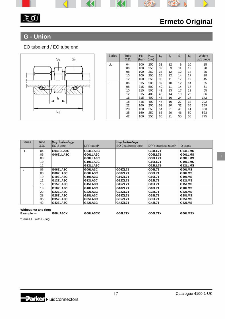
Ermeto Original
I 7 Catalogue 4100-1-UK
I
FluidConnectors
Series Tube Dry Technology Dry TechnologyO.D. EO-2 steel DPR steel* EO-2 stainless steel DPR stainless steel* D brass
LL 04 G04ZLLA3C G04LLA3C G04LL71 G04LLMS06 G06ZLLA3C G06LLA3C G06LL71 G06LLMS08 G08LLA3C G08LL71 G08LLMS10 G10LLA3C G10LL71 G10LLMS12 G12LLA3C G12LL71 G12LLMS
L 06 G06ZLA3C G06LA3C G06ZL71 G06L71 G06LMS08 G08ZLA3C G08LA3C G08ZL71 G08L71 G08LMS10 G10ZLA3C G10LA3C G10ZL71 G10L71 G10LMS12 G12ZLA3C G12LA3C G12ZL71 G12L71 G12LMS15 G15ZLA3C G15LA3C G15ZL71 G15L71 G15LMS18 G18ZLA3C G18LA3C G18ZL71 G18L71 G18LMS22 G22ZLA3C G22LA3C G22ZL71 G22L71 G22LMS28 G28ZLA3C G28LA3C G28ZL71 G28L71 G28LMS35 G35ZLA3C G35LA3C G35ZL71 G35L71 G35LMS42 G42ZLA3C G42LA3C G42ZL71 G42L71 G42LMS
Without nut and ring:Example → G06LA3CX G06LA3CX G06L71X G06L71X G06LMSX
*Series LL with D-ring.
G - Union
EO tube end / EO tube end
Series Tube PN Pmax L1 l1 S1 S2 WeightO.D. (bar) (bar) g./1 piece
LL 04 100 250 31 12 9 10 1506 100 250 32 9 11 12 2008 100 250 35 12 12 14 2510 100 250 35 12 14 17 3812 100 250 35 11 17 19 45
L 06 315 500 39 10 12 14 3508 315 500 40 11 14 17 5110 315 500 42 13 17 19 6512 315 400 43 14 19 22 8615 315 400 46 16 24 27 14218 315 400 48 16 27 32 20222 160 250 52 20 32 36 26928 160 250 54 21 41 41 33335 160 250 63 20 46 50 52342 160 250 66 21 55 60 775
S2S1
L1
l1

Ermeto Original
I 8 Catalogue 4100-1-UK
FluidConnectors
I
W - Union Elbow
EO tube end / EO tube end
Series Tube Dry Technology Dry TechnologyO.D. EO-2 steel DPR steel* EO-2 stainless steel DPR stainless steel* D brass
LL 04 W04ZLLA3C W04LLA3C W04LL71 W04LLMS06 W06ZLLA3C W06LLA3C W06LL71 W06LLMS08 W08LLA3C W08LL71 W08LLMS10 W10LLA3C W10LL71 W10LLMS12 W12LLA3C W12LL71 W12LLMS
L 06 W06ZLA3C W06LA3C W06ZL71 W06L71 W06LMS08 W08ZLA3C W08LA3C W08ZL71 W08L71 W08LMS10 W10ZLA3C W10LA3C W10ZL71 W10L71 W10LMS12 W12ZLA3C W12LA3C W12ZL71 W12L71 W12LMS15 W15ZLA3C W15LA3C W15ZL71 W15L71 W15LMS18 W18ZLA3C W18LA3C W18ZL71 W18L71 W18LMS22 W22ZLA3C W22LA3C W22ZL71 W22L71 W22LMS28 W28ZLA3C W28LA3C W28ZL71 W28L71 W28LMS35 W35ZLA3C W35LA3C W35ZL71 W35L71 W35LMS42 W42ZLA3C W42LA3C W42ZL71 W42L71 W42LMS
Without nut and ring:Example → W06LA3CX W06LA3CX W06L71X W06L71X W06LMSX
*Series LL with D-ring.
Series Tube PN Pmax L2 l2 S2 S3 S3** WeightO.D. (bar) (bar) g./1 piece
LL 04 100 250 21 11.0 10 9 9 2306 100 250 21 9.5 12 11 9 2808 100 250 23 11.5 14 12 12 3810 100 250 24 12.5 17 14 12 5612 100 250 25 13.0 19 17 14 72
L 06 315 500 27 12.0 14 12 12 5208 315 500 29 14.0 17 14 12 7710 315 500 30 15.0 19 17 14 10012 315 400 32 17.0 22 19 17 13615 315 400 36 21.0 27 19 19 16718 315 400 40 23.5 32 24 24 24922 160 250 44 27.5 36 27 27 33028 160 250 47 30.5 41 36 36 45435 160 250 56 34.5 50 41 41 71042 160 250 63 40.0 60 50 50 1088
**only stainless steelS2
S3
l2
L2
S2
S3
l2
L2
Profile body (steel and brass):Series LL 4–12 mm Tube O.D.Series L 6–12 mm Tube O.D.

Ermeto Original
I 9 Catalogue 4100-1-UK
I
FluidConnectors
T - Union Tee
All 3 ends EO tube end
Series Tube Dry Technology Dry TechnologyO.D. EO-2 steel DPR steel* EO-2 stainless steel DPR stainless steel* D brass
LL 04 T04ZLLA3C T04LLA3C T04LL71 T04LLMS06 T06ZLLA3C T06LLA3C T06LL71 T06LLMS08 T08LLA3C T08LL71 T08LLMS10 T10LLA3C T10LL71 T10LLMS12 T12LLA3C T12LL71 T12LLMS
L 06 T06ZLA3C T06LA3C T06ZL71 T06L71 T06LMS08 T08ZLA3C T08LA3C T08ZL71 T08L71 T08LMS10 T10ZLA3C T10LA3C T10ZL71 T10L71 T10LMS12 T12ZLA3C T12LA3C T12ZL71 T12L71 T12LMS15 T15ZLA3C T15LA3C T15ZL71 T15L71 T15LMS18 T18ZLA3C T18LA3C T18ZL71 T18L71 T18LMS22 T22ZLA3C T22LA3C T22ZL71 T22L71 T22LMS28 T28ZLA3C T28LA3C T28ZL71 T28L71 T28LMS35 T35ZLA3C T35LA3C T35ZL71 T35L71 T35LMS42 T42ZLA3C T42LA3C T42ZL71 T42L71 T42LMS
Without nut and ring:Example → T06LA3CX T06LA3CX T06L71X T06L71X T06LMSX
*Series LL with D-ring.
Series Tube PN Pmax L2 I2 S2 S3 S3** WeightO.D. (bar) (bar) g./1 piece
LL 04 100 250 21 11.0 10 9 9 2906 100 250 21 9.5 12 11 9 3708 100 250 23 11.5 14 12 12 5010 100 250 24 12.5 17 14 12 7112 100 250 27 15.0 19 14 14 69
L 06 315 500 27 12.0 14 12 12 7208 315 500 29 14.0 17 14 12 10410 315 500 30 15.0 19 14 14 10512 315 400 32 17.0 22 17 17 14015 315 400 36 21.0 27 19 19 23718 315 400 40 23.5 32 24 24 35622 160 250 44 27.5 36 27 27 46228 160 250 47 30.5 41 36 36 61035 160 250 56 34.5 50 41 41 95342 160 250 63 40.0 60 50 50 1410
**only stainless steel
S2 S3
L2
I2
S2 S3
L2
I2
Profile body (steel and brass):Series LL 4–10 mm Tube O.D.Series L 6+8 mm Tube O.D.

Ermeto Original
I 10 Catalogue 4100-1-UK
FluidConnectors
I
Series Tube G PN Pmax L1 l1 i S2 S1 d7 WeightO.D. (bar) (bar) g./1 piece
LL 04 G1/8A 100 250 19 9.5 8 10 14 14 1606 G1/8A 100 250 20 8.0 8 12 14 14 17
L 06 G1/8A 315 500 23 8.5 8 14 14 14 2506 G1/4A 315 500 25 10.0 12 14 19 19 4006 G3/8A 315 500 26 11.5 12 14 22 22 5006 G1/2A 315 500 27 12.0 14 14 27 27 7208 G1/4A 315 500 25 10.0 12 17 19 19 4408 G1/8A 315 500 24 9.5 8 17 14 14 3308 G3/8A 315 500 26 11.5 12 17 22 22 6208 G1/2A 315 500 27 12.0 14 17 27 27 9110 G1/4A 315 500 26 11.0 12 19 19 19 4810 G1/8A 315 500 25 10.5 8 19 17 14 4210 G3/8A 315 500 27 12.5 12 19 22 22 6410 G1/2A 315 500 28 13.0 14 19 27 27 9012 G3/8A 315 400 27 12.5 12 22 22 22 7012 G1/8A 315 400 26 11.5 8 22 19 14 7012 G1/4A 315 400 27 12.0 12 22 19 19 5712 G1/2A 315 400 28 13.0 14 22 27 27 9612 G3/4A 315 400 29 14.0 16 22 32 32 14715 G1/2A 315 400 29 14.0 14 27 27 27 11815 G3/8A 315 400 29 13.5 12 27 24 22 10015 G3/4A 315 400 30 15.0 16 27 32 32 16318 G1/2A 315 400 31 14.5 14 32 27 27 13818 G3/8A 315 400 30 14.0 12 32 27 22 13918 G3/4A 315 400 31 14.5 16 32 32 32 17822 G3/4A 160 250 33 16.5 16 36 32 32 19122 G1/2A 160 250 33 16.5 14 36 32 27 18022 G1A 160 250 34 17.5 18 36 41 40 27828 G1A 160 250 34 17.5 18 41 41 40 26828 G3/4A 160 250 34 17.5 16 41 41 32 26828 G11/4A 160 250 35 18.5 20 41 50 50 41435 G11/4A 160 250 39 17.5 20 50 50 50 42835 G1A 160 250 39 17.5 18 50 46 40 40735 G11/2A 160 250 41 19.5 22 50 55 55 57942 G11/2A 160 250 42 19.0 22 60 55 55 58342 G1A 160 250 42 19.0 18 60 55 40 55942 G11/4A 160 250 42 19.0 20 60 55 50 587
GE-R-ED - Male Stud Connector
EO tube end / Male BSPP threadDIN 3852, Form E: Eolastic Seal ED
S2S1
L1
d 7
il1
G

Ermeto Original
I 11 Catalogue 4100-1-UK
I
FluidConnectors
S2S1
L1
d 7
il1
GGE-R-ED - Male Stud Connector
EO tube end / Male BSPP threadDIN 3852, Form E: Eolastic Seal ED
Series Tube G Dry Technology Dry TechnologyO.D. EO-2 steel DPR steel* EO-2 stainless steel DPR stainless steel* D brass
LL 04 R1/8A GE04ZLLREDA3C GE04LLREDA3C GE04LLRED7106 R1/8A GE06ZLLREDA3C GE06LLREDA3C GE06LLRED71
L 06 G1/8A GE06ZLREDA3C GE06LREDA3C GE06ZLRED71 GE06LRED71 GE06LREDMS06 G1/4A GE06ZLR1/4EDA3C GE06LR1/4EDA3C GE06ZLR1/4ED71 GE06LR1/4ED7106 G3/8A GE06ZLR3/8EDA3C GE06LR3/8EDA3C GE06ZLR3/8ED71 GE06LR3/8ED7106 G1/2A GE06ZLR1/2EDA3C GE06LR1/2EDA3C GE06ZLR1/2ED71 GE06LR1/2ED7108 G1/4A GE08ZLREDA3C GE08LREDA3C GE08ZLRED71 GE08LRED71 GE08LREDMS08 G1/8A GE08ZLR1/8EDA3C GE08LR1/8EDA3C GE08ZLR1/8ED71 GE08LR1/8ED7108 G3/8A GE08ZLR3/8EDA3C GE08LR3/8EDA3C GE08ZLR3/8ED71 GE08LR3/8ED7108 G1/2A GE08ZLR1/2EDA3C GE08LR1/2EDA3C GE08ZLR1/2ED71 GE08LR1/2ED7110 G1/4A GE10ZLREDA3C GE10LREDA3C GE10ZLRED71 GE10LRED71 GE10LREDMS10 G1/8A GE10ZLR1/8EDA3C GE10LR1/8EDA3C GE10ZLR1/8ED71 GE10LR1/8ED7110 G3/8A GE10ZLR3/8EDA3C GE10LR3/8EDA3C GE10ZLR3/8ED71 GE10LR3/8ED7110 G1/2A GE10ZLR1/2EDA3C GE10LR1/2EDA3C GE10ZLR1/2ED71 GE10LR1/2ED7112 G3/8A GE12ZLREDA3C GE12LREDA3C GE12ZLRED71 GE12LRED71 GE12LREDMS12 G1/8A GE12ZLR1/8ED71 GE12LR1/8ED7112 G1/4A GE12ZLR1/4EDA3C GE12LR1/4EDA3C GE12ZLR1/4ED71 GE12LR1/4ED7112 G1/2A GE12ZLR1/2EDA3C GE12LR1/2EDA3C GE12ZLR1/2ED71 GE12LR1/2ED7112 G3/4A GE12ZLR3/4EDA3C GE12LR3/4EDA3C15 G1/2A GE15ZLREDA3C GE15LREDA3C GE15ZLRED71 GE15LRED71 GE15LREDMS15 G3/8A GE15ZLR3/8EDA3C GE15LR3/8EDA3C GE15ZLR3/8ED71 GE15LR3/8ED7115 G3/4A GE15ZLR3/4EDA3C GE15LR3/4EDA3C GE15ZLR3/4ED71 GE15LR3/4ED7118 G1/2A GE18ZLREDA3C GE18LREDA3C GE18ZLRED71 GE18LRED71 GE18LREDMS18 G3/8A GE18ZLR3/8EDA3C GE18LR3/8EDA3C GE18ZLR3/8ED71 GE18LR3/8ED7118 G3/4A GE18ZLR3/4EDA3C GE18LR3/4EDA3C GE18ZLR3/4ED71 GE18LR3/4ED7122 G3/4A GE22ZLREDA3C GE22LREDA3C GE22ZLRED71 GE22LRED71 GE22LREDMS22 G1/2A GE22ZLR1/2EDA3C GE22LR1/2EDA3C GE22ZLR1/2ED71 GE22LR1/2ED7122 G1A GE22ZLR1EDA3C GE22LR1EDA3C GE22ZLR1ED71 GE22LR1ED7128 G1A GE28ZLREDA3C GE28LREDA3C GE28ZLRED71 GE28LRED71 GE28LREDMS28 G3/4A GE28ZLR3/4EDA3C GE28LR3/4EDA3C GE28ZLR3/4ED71 GE28LR3/4ED7128 G11/4A GE28ZLR11/4EDA3C GE28LR11/4EDA3C GE28ZLR11/4ED71 GE28LR11/4ED7135 G11/4A GE35ZLREDA3C GE35LREDA3C GE35ZLRED71 GE35LRED71 GE35LREDMS35 G1A GE35ZLR1EDA3C GE35LR1EDA3C GE35ZLR1ED71 GE35LR1ED7135 G11/2A GE35ZLR11/2ED71 GE35LR11/2ED7142 G11/2A GE42ZLREDA3C GE42LREDA3C GE42ZLRED71 GE42LRED71 GE42LREDMS42 G1A GE42ZLR1ED71 GE42LR1ED7142 G11/4A GE42ZLR11/4ED71 GE42LR11/4ED71
Without nut and ring:Example → GE06LREDOMDA3C GE06LREDOMD71 GE06LREDOMDMS
GE06LREDOMDA3C GE06LREDOMD71*Series LL with D-ring.

Ermeto Original
I 12 Catalogue 4100-1-UK
FluidConnectors
I
S2S1
L1
d 7
il1
G
GE-M-ED - Male Stud Connector
EO tube end / Male metric parallel thread with Eolastic seal ED
Series Tube G PN Pmax L1 l1 i S2 S1 d7 WeightO.D. (bar) (bar) g./1 piece
L 06 M10×1 315 500 23 8.5 8 14 14 14 2508 M12×1.5 315 500 25 10.0 12 17 17 17 3910 M14×1.5 315 500 26 11.0 12 19 19 19 5010 M12×1.5 315 500 26 11.0 12 19 17 17 4610 M16×1.5 315 500 24 12.5 12 19 22 22 6110 M18×1.5 315 500 27 12.5 12 19 24 24 7110 M22×1.5 315 500 29 14.0 14 19 27 27 10112 M16×1.5 315 400 27 12.5 12 22 22 22 6812 M14×1.5 315 400 26 11.0 12 22 19 19 5712 M18×1.5 315 400 27 12.5 12 22 24 24 7512 M22×1.5 315 400 29 14.0 14 22 27 27 10315 M18×1.5 315 400 29 13.5 12 27 24 24 9715 M16×1.5 315 400 28 13.0 12 27 24 22 9515 M22×1.5 315 400 30 15.0 14 27 27 27 12318 M22×1.5 315 400 31 14.5 14 32 27 27 14218 M18×1.5 315 400 30 14.0 12 32 27 24 13622 M26×1.5 160 250 33 16.5 16 36 32 32 19222 M22×1.5 160 250 33 16.5 14 36 32 32 18628 M33×2 160 250 34 17.5 18 41 41 40 26735 M42×2 160 250 39 17.5 20 50 50 50 43742 M48×2 160 250 42 19.0 22 60 55 55 595

Ermeto Original
I 13 Catalogue 4100-1-UK
I
FluidConnectors
GE-M-ED - Male Stud Connector
EO tube end / Male metric parallel thread with Eolastic seal ED
S2S1
L1
d 7
il1
G
Series Tube G Dry Technology Dry TechnologyO.D. EO-2 steel DPR steel EO-2 stainless steel DPR stainless steel
L 06 M10x1 GE06ZLMEDA3C GE06LMEDA3C GE06ZLMED71 GE06LMED7108 M12x1.5 GE08ZLMEDA3C GE08LMEDA3C GE08ZLMED71 GE08LMED7110 M14x1.5 GE10ZLMEDA3C GE10LMEDA3C GE10ZLMED71 GE10LMED7110 M12x1.5 GE10ZLM12x1.5ED71 GE10LM12X1.5ED7110 M16x1.5 GE10ZLM16X1.5EDA3C GE10LM16X1.5EDA3C GE10ZLM16x1.5ED71 GE10LM16X1.5ED7110 M18x1.5 GE10ZLM18X1.5EDA3C GE10LM18X1.5EDA3C10 M22x1.5 GE10ZLM22X1.5EDA3C GE10LM22X1.5EDA3C12 M16x1.5 GE12ZLMEDA3C GE12LMEDA3C GE12ZLMED71 GE12LMED7112 M14x1.5 GE12ZLM14X1.5EDA3C GE12LM14X1.5EDA3C12 M18x1.5 GE12ZLM18X1.5EDA3C GE12LM18X1.5EDA3C12 M22x1.5 GE12ZLM22X1.5EDA3C GE12LM22X1.5EDA3C15 M18x1.5 GE15ZLMEDA3C GE15LMEDA3C GE12ZLMED71 GE15LMED7115 M16x1.5 GE15ZLM16X1.5EDA3C GE15LM16X1.5EDA3C15 M22x1.5 GE15ZLM22X1.5EDA3C GE15LM22X1.5EDA3C18 M22x1.5 GE18ZLMEDA3C GE18LMEDA3C GE18ZLMED71 GE18LMED7118 M18x1.5 GE18ZLM18X1.5EDA3C GE18LM18X1.5EDA3C22 M26x1.5 GE22ZLMEDA3C GE22LMEDA3C GE22ZLMED71 GE22LMED7122 M22x1.5 GE22ZLM22X1.5EDA3C GE22LM22X1.5EDA3C28 M33x2 GE28ZLMEDA3C GE28LMEDA3C GE28ZLMED71 GE28LMED7135 M42x2 GE35ZLMEDA3C GE35LMEDA3C GE35ZLMED71 GE35LMED7142 M48x2 GE42ZLMEDA3C GE42LMEDA3C GE42ZLMED71 GE42LMED71
Without nut and ring:Example → GE06LMEDOMDA3C GE06LMEDOMDA3C GE06LMEDOMD71 GE06LMEDOMD71*Series LL with D-ring.
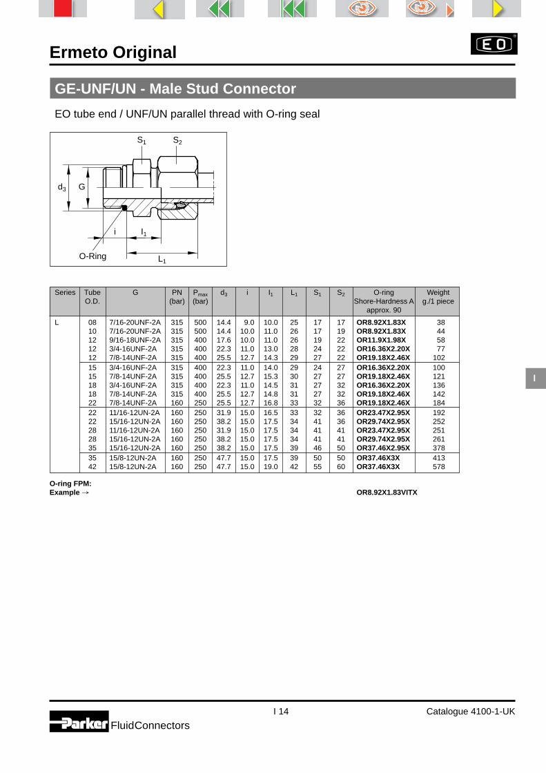
Ermeto Original
I 14 Catalogue 4100-1-UK
FluidConnectors
I
GE-UNF/UN - Male Stud Connector
EO tube end / UNF/UN parallel thread with O-ring seal
Series Tube G PN Pmax d3 i I1 L1 S1 S2 O-ring WeightO.D. (bar) (bar) Shore-Hardness A g./1 piece
approx. 90
L 08 7/16-20UNF-2A 315 500 14.4 9.0 10.0 25 17 17 OR8.92X1.83X 3810 7/16-20UNF-2A 315 500 14.4 10.0 11.0 26 17 19 OR8.92X1.83X 4412 9/16-18UNF-2A 315 400 17.6 10.0 11.0 26 19 22 OR11.9X1.98X 5812 3/4-16UNF-2A 315 400 22.3 11.0 13.0 28 24 22 OR16.36X2.20X 7712 7/8-14UNF-2A 315 400 25.5 12.7 14.3 29 27 22 OR19.18X2.46X 10215 3/4-16UNF-2A 315 400 22.3 11.0 14.0 29 24 27 OR16.36X2.20X 10015 7/8-14UNF-2A 315 400 25.5 12.7 15.3 30 27 27 OR19.18X2.46X 12118 3/4-16UNF-2A 315 400 22.3 11.0 14.5 31 27 32 OR16.36X2.20X 13618 7/8-14UNF-2A 315 400 25.5 12.7 14.8 31 27 32 OR19.18X2.46X 14222 7/8-14UNF-2A 160 250 25.5 12.7 16.8 33 32 36 OR19.18X2.46X 18422 11/16-12UN-2A 160 250 31.9 15.0 16.5 33 32 36 OR23.47X2.95X 19222 15/16-12UN-2A 160 250 38.2 15.0 17.5 34 41 36 OR29.74X2.95X 25228 11/16-12UN-2A 160 250 31.9 15.0 17.5 34 41 41 OR23.47X2.95X 25128 15/16-12UN-2A 160 250 38.2 15.0 17.5 34 41 41 OR29.74X2.95X 26135 15/16-12UN-2A 160 250 38.2 15.0 17.5 39 46 50 OR37.46X2.95X 37835 15/8-12UN-2A 160 250 47.7 15.0 17.5 39 50 50 OR37.46X3X 41342 15/8-12UN-2A 160 250 47.7 15.0 19.0 42 55 60 OR37.46X3X 578
O-ring FPM:Example → OR8.92X1.83VITX
S2S1
L1
d3 G
I1i
O-Ring

Ermeto Original
I 15 Catalogue 4100-1-UK
I
FluidConnectors
GE-UNF/UN - Male Stud Connector
EO tube end / UNF/UN parallel thread with O-ring seal
Series Tube G Dry Technology Dry TechnologyO.D. EO-2 steel DPR steel EO-2 stainless steel DPR stainless steel
L 08 7/16-20UNF-2A GE08ZL7/16UNFA3C GE08L7/16UNFA3C GE08ZL7/16UNF71 GE08L7/16UNF7110 7/16-20UNF-2A GE10ZL7/16UNFA3C GE10L7/16UNFA3C GE10ZL7/16UNF71 GE10L7/16UNF7112 9/16-18UNF-2A GE12ZL9/16UNFA3C GE12L9/16UNFA3C GE12ZL9/16UNF71 GE12L9/16UNF7112 3/4-16UNF-2A GE12ZL3/4UNFA3C GE12L3/4UNFA3C GE12ZL3/4UNF71 GE12L3/4UNF7112 7/8-14UNF-2A GE12ZL7/8UNFA3C GE12L7/8UNFA3C GE12ZL7/8UNF71 GE12L7/8UNF7115 3/4-16UNF-2A GE15ZL3/4UNFA3C GE15L3/4UNFA3C GE15ZL3/4UNF71 GE15L3/4UNF7115 7/8-14UNF-2A GE15ZL7/8UNFA3C GE15L7/8UNFA3C GE15ZL7/8UNF71 GE15L7/8UNF7118 3/4-16UNF-2A GE18ZL3/4UNFA3C GE18L3/4UNFA3C GE18ZL3/4UNF71 GE18L3/4UNF7118 7/8-14UNF-2A GE18ZL7/8UNFA3C GE18L7/8UNFA3C GE18ZL7/8UNF71 GE18L7/8UNF7122 7/8-14UNF-2A GE22ZL7/8UNFA3C GE22L7/8UNFA3C GE22ZL7/8UNF71 GE22L7/8UNF7122 11/16-12UN-2A GE22ZL11/16UNA3C GE22L11/16UNA3C GE22ZL11/16UNF71 GE22L11/16UNF7122 15/16-12UN-2A GE22ZL15/16UNA3C GE22L15/16UNA3C GE22ZL15/16UNF71 GE22L15/16UNF7128 11/16-12UN-2A GE28ZL11/16UNA3C GE28L11/16UNA3C GE28ZL11/16UNF71 GE28L11/16UNF7128 15/16-12UN-2A GE28ZL15/16UNA3C GE28L15/16UNA3C GE28ZL15/16UNF71 GE28L15/16UNF7135 15/16-12UN-2A GE35ZL15/16UNA3C GE35L15/16UNA3C GE35ZL15/16UNF71 GE35L15/16UNF7135 15/8-12UN-2A GE35ZL15/8UNA3C GE35L15/8UNA3C GE35ZL15/8UNF71 GE35L15/8UNF7142 15/8-12UN-2A GE42ZL15/8UNA3C GE42L15/8UNA3C GE42ZL15/8UNF71 GE42L15/8UNF71
Without nut and ring:Example → GE08L7/16UNFOMDA3C GE08L7/16UNFOMD71
GE08L7/16UNFOMDA3C GE08L7/16UNFOMD71
S2S1
L1
d3 G
I1i
O-Ring

Ermeto Original
I 16 Catalogue 4100-1-UK
FluidConnectors
I
Series Tube Dry Technology Dry TechnologyO.D. EO-2 steel DPR steel EO-2 stainless steel DPR stainless steel D brass
L 06 SV06ZLA3C SV06LA3C SV06ZL71 SV06L71 SV06LMS08 SV08ZLA3C SV08LA3C SV08ZL71 SV08L71 SV08LMS10 SV10ZLA3C SV10LA3C SV10ZL71 SV10L71 SV10LMS12 SV12ZLA3C SV12LA3C SV12ZL71 SV12L71 SV12LMS15 SV15ZLA3C SV15LA3C SV15ZL71 SV15L71 SV15LMS18 SV18ZLA3C SV18LA3C SV18ZL71 SV18L71 SV18LMS22 SV22ZLA3C SV22LA3C SV22ZL71 SV22L71 SV22LMS28 SV28ZLA3C SV28LA3C SV28ZL71 SV28L71 SV28LMS35 SV35ZLA3C SV35LA3C SV35ZL71 SV35L7142 SV42ZLA3C SV42LA3C SV42ZL71 SV42L71
Without nut and ring:Example → SV06LOMDA3C SV06LOMDA3C SV06LOMD71 SV06LOMD71 SV06LOMDMS
SV - Bulkhead Union
EO tube end / EO tube end
D = 16 mm max.
Series Tube M PN Pmax S1 S2 S4 L1 l1 L3 l3 WeightO.D. (bar) (bar) g./1 piece
L 06 M 12 × 1.5 315 500 17 14 17 22 7.0 42 27.0 6108 M 14 × 1.5 315 500 19 17 19 23 8.0 42 27.0 8410 M 16 × 1.5 315 500 22 19 22 25 10.0 43 28.0 10912 M 18 × 1.5 315 400 24 22 24 25 10.0 44 29.0 13615 M 22 × 1.5 315 400 27 27 30 27 12.0 46 31.0 22218 M 26 × 1.5 315 400 32 32 36 30 13.5 49 32.5 33422 M 30 × 2 160 250 36 36 41 33 16.5 51 34.5 43028 M 36 × 2 160 250 41 41 46 35 18.5 52 35.5 56635 M 45 × 2 160 250 50 50 55 40 18.5 58 36.5 85842 M 52 × 2 160 250 60 60 65 42 19.0 59 36.0 1236
S1 S4 S2
L3L1
l3l1
D
M
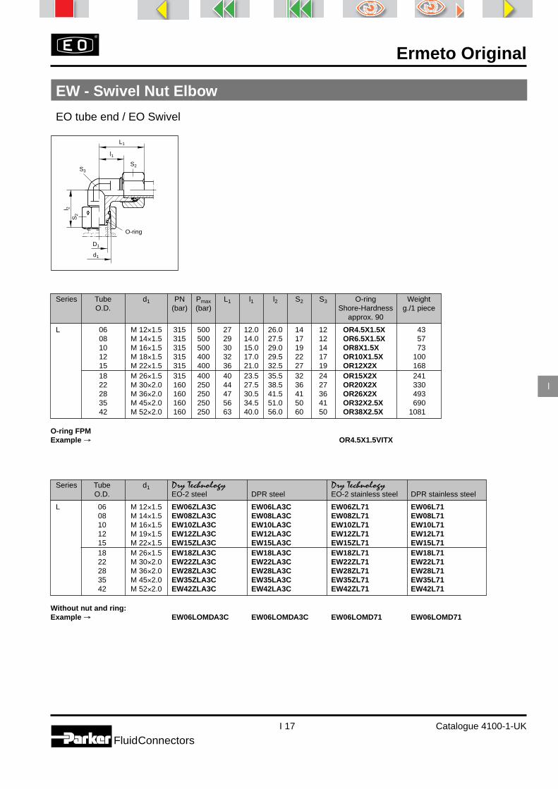
Ermeto Original
I 17 Catalogue 4100-1-UK
I
FluidConnectors
EW - Swivel Nut Elbow
EO tube end / EO Swivel
d1
D1
O-ring
S2
S2
l 2
S3
l1
L1
Series Tube d1 PN Pmax L1 l1 l2 S2 S3 O-ring WeightO.D. (bar) (bar) Shore-Hardness g./1 piece
approx. 90
L 06 M 12×1.5 315 500 27 12.0 26.0 14 12 OR4.5X1.5X 4308 M 14×1.5 315 500 29 14.0 27.5 17 12 OR6.5X1.5X 5710 M 16×1.5 315 500 30 15.0 29.0 19 14 OR8X1.5X 7312 M 18×1.5 315 400 32 17.0 29.5 22 17 OR10X1.5X 10015 M 22×1.5 315 400 36 21.0 32.5 27 19 OR12X2X 16818 M 26×1.5 315 400 40 23.5 35.5 32 24 OR15X2X 24122 M 30×2.0 160 250 44 27.5 38.5 36 27 OR20X2X 33028 M 36×2.0 160 250 47 30.5 41.5 41 36 OR26X2X 49335 M 45×2.0 160 250 56 34.5 51.0 50 41 OR32X2.5X 69042 M 52×2.0 160 250 63 40.0 56.0 60 50 OR38X2.5X 1081
O-ring FPMExample → OR4.5X1.5VITX
Series Tube d1 Dry Technology Dry TechnologyO.D. EO-2 steel DPR steel EO-2 stainless steel DPR stainless steel
L 06 M 12×1.5 EW06ZLA3C EW06LA3C EW06ZL71 EW06L7108 M 14×1.5 EW08ZLA3C EW08LA3C EW08ZL71 EW08L7110 M 16×1.5 EW10ZLA3C EW10LA3C EW10ZL71 EW10L7112 M 19×1.5 EW12ZLA3C EW12LA3C EW12ZL71 EW12L7115 M 22×1.5 EW15ZLA3C EW15LA3C EW15ZL71 EW15L7118 M 26×1.5 EW18ZLA3C EW18LA3C EW18ZL71 EW18L7122 M 30×2.0 EW22ZLA3C EW22LA3C EW22ZL71 EW22L7128 M 36×2.0 EW28ZLA3C EW28LA3C EW28ZL71 EW28L7135 M 45×2.0 EW35ZLA3C EW35LA3C EW35ZL71 EW35L7142 M 52×2.0 EW42ZLA3C EW42LA3C EW42ZL71 EW42L71
Without nut and ring:Example → EW06LOMDA3C EW06LOMDA3C EW06LOMD71 EW06LOMD71

Ermeto Original
I 18 Catalogue 4100-1-UK
FluidConnectors
I
ET - Swivel Nut Branch Tee
EO tube ends / EO Swivel
Series Tube d1 PN Pmax L1 l1 l2 S2 S3 O-ring WeightO.D. (bar) (bar) Shore-Hardness g./1 piece
approx. 90
L 06 M 12×1.5 315 500 27 12.0 26.0 14 12 OR4.5X1.5X 5908 M 14×1.5 315 500 29 14.0 27.5 17 12 OR6.5X1.5X 8210 M 16×1.5 315 500 30 15.0 29.0 19 14 OR8X1.5X 10512 M 18×1.5 315 400 32 17.0 29.5 22 17 OR10X1.5X 13915 M 22×1.5 315 400 36 21.0 32.5 27 19 OR12X2X 23718 M 26×1.5 315 400 40 23.5 35.5 32 24 OR15X2X 34222 M 30×2.0 160 250 44 27.5 38.5 36 27 OR20X2X 45328 M 36×2.0 160 250 47 30.5 41.5 41 36 OR26X2X 65935 M 45×2.0 160 250 56 34.5 51.0 50 41 OR32X2.5X 96542 M 52×2.0 160 250 63 40.0 56.0 60 50 OR38X2.5X 1464
O-ring FPMExample → OR4.5X1.5VITX
Series Tube d1 Dry Technology Dry TechnologyO.D. EO-2 steel DPR steel EO-2 stainless steel DPR stainless steel
L 06 M 12×1.5 ET06ZLA3C ET06LA3C ET06ZL71 ET06L7108 M 14×1.5 ET08ZLA3C ET08LA3C ET08ZL71 ET08L7110 M 16×1.5 ET10ZLA3C ET10LA3C ET10ZL71 ET10L7112 M 18×1.5 ET12ZLA3C ET12LA3C ET12ZL71 ET12L7115 M 22×1.5 ET15ZLA3C ET15LA3C ET15ZL71 ET15L7118 M 26×1.5 ET18ZLA3C ET18LA3C ET18ZL71 ET18L7122 M 30×2.0 ET22ZLA3C ET22LA3C ET22ZL71 ET22L7128 M 36×2.0 ET28ZLA3C ET28LA3C ET28ZL71 ET28L7135 M 45×2.0 ET35ZLA3C ET35LA3C ET35ZL71 ET35L7142 M 52×2.0 ET42ZLA3C ET42LA3C ET42ZL71 ET42L71
Without nut and ring:Example → ET06LOMDA3C ET06LOMDA3C ET06LOMD71 ET06LOMD71
d1
D1
O-ring*
S2
l 2
S3S2
l1
L1

Ermeto Original
I 19 Catalogue 4100-1-UK
I
FluidConnectors
EL - Swivel Nut Run Tee
EO tube ends / EO Swivel
Series Tube d1 PN Pmax L1 l1 L2 l2 S2 S3 O-ring WeightO.D. (bar) (bar) Shore-Hardness g./1 piece
approx. 90
L 06 M 12 × 1.5 315 500 27 12.0 53 26.0 14 12 OR4.5X1.5X 5908 M 14 × 1.5 315 500 29 14.0 56 27.5 17 12 OR6.5X1.5X 8710 M 16 × 1.5 315 500 30 15.0 59 29.0 19 14 OR8X1.5X 10412 M 18 × 1.5 315 400 32 17.0 61 29.5 22 17 OR10X1.5X 14015 M 22 × 1.5 315 400 36 21.0 69 32.5 27 19 OR12X2X 23718 M 26 × 1.5 315 400 40 23.5 75 35.5 32 24 OR15X2X 34122 M 30 × 2 160 250 44 27.5 82 38.5 36 27 OR20X2X 45028 M 36 × 2 160 250 47 30.5 89 41.5 41 36 OR26X2X 60735 M 45 × 2 160 250 56 34.5 107 51.0 50 41 OR32X2.5X 97942 M 52 × 2 160 250 63 40.0 119 56.0 60 50 OR38X2.5X 1465
O-ring FPMExample → OR4.5X1.5VITX
Series Tube d1 Dry Technology Dry TechnologyO.D. EO-2 steel DPR steel EO-2 stainless steel DPR stainless steel
L 06 M 12 × 1.5 EL06ZLA3C EL06LA3C EL06ZL71 EL06L7108 M 14 × 1.5 EL08ZLA3C EL08LA3C EL08ZL71 EL08L7110 M 16 × 1.5 EL10ZLA3C EL10LA3C EL10ZL71 EL10L7112 M 18 × 1.5 EL12ZLA3C EL12LA3C EL12ZL71 EL12L7115 M 22 × 1.5 EL15ZLA3C EL15LA3C EL15ZL71 EL15L7118 M 26 × 1.5 EL18ZLA3C EL18LA3C EL18ZL71 EL18L7122 M 30 × 2 EL22ZLA3C EL22LA3C EL22ZL71 EL22L7128 M 36 × 2 EL28ZLA3C EL28LA3C EL28ZL71 EL28L7135 M 45 × 2 EL35ZLA3C EL35LA3C EL35ZL71 EL35L7142 M 52 × 2 EL42ZLA3C EL42LA3C EL42ZL71 EL42L71
Without nut and ring:Example → EL06LOMDA3C EL06LOMDA3C EL06LOMD71 ET06LOMD71
d1
D1S2
O-ring*
l1
L1
S2
L 2
S3
l 2

Ermeto Original
I 20 Catalogue 4100-1-UK
FluidConnectors
I
WEE-R - Adjustable Locknut Elbow
EO tube end / Male BSPP thread with O-ring sealfor ports with smallor wide spot face
Series Tube G Dry TechnologyO.D. EO-2 steel DPR steel
LL 04 G 1/8A WEE04ZLLRA3C WEE04LLRA3C06 G 1/8A WEE06ZLLRA3C WEE06LLRA3C
L 06 G 1/8A WEE06ZLRA3C WEE06LRA3C08 G 1/4A WEE08ZLRA3C WEE08LRA3C10 G 1/4A WEE10ZLRA3C WEE10LRA3C12 G 3/8A WEE12ZLRA3C WEE12LRA3C15 G 1/2A WEE15ZLRA3C WEE15LRA3C18 G 1/2A WEE18ZLRA3C WEE18LRA3C22 G 3/4A WEE22ZLRA3C WEE22LRA3C28 G 1A WEE28ZLRA3C WEE28LRA3C35 G 1 1/4A WEE35ZLRA3C WEE35LRA3C42 G 1 1/2A WEE42ZLRA3C WEE42LRA3C
Without nut and ring:Example → WEE06LROMDA3C WEE06LROMDA3C
*Series LL with D-ring.
Series Tube G PN Pmax L2 I2 I3 i D1 S2 S3 S4 Assembly O-ring Retaining WeightO.D. (bar) (bar) torque Shore-Hardness ring g./1 piece
(Nm) ±10% approx. 90 small
LL 04 G 1/8A 250 315 21 11.3 20 7.1 15 10 11 14 OR8X1.88X RRS1/3 3006 G 1/8A 250 315 21 11.3 20 7.1 15 12 11 14 OR8X1.88X RRS1/8 32
L 06 G 1/8A 315 420 29 14.0 19 7.0 15 14 14 14 25 OR8X1.88X RRS1/8 6608 G 1/4A 315 420 31 16.0 23 9.0 20 17 14 19 50 OR10.77X2.62X RRS1/4 6610 G 1/4A 315 420 32 17.0 25 9.0 20 19 19 19 50 OR10.77X2.62X RRS1/4 11912 G 3/8A 250 400 34 19.0 28 9.0 23 22 19 22 80 OR13.94X2.62X RRS3/8 13815 G 1/2A 250 400 36 21.0 30 13.0 28 27 22 27 105 OR17X3X RRS1/2 28318 G 1/2A 250 400 40 24.0 36 13.0 28 32 27 27 105 OR17X3X RRS1/2 34422 G 3/4A 160 250 44 28.0 36 13.0 33 36 30 36 220 OR23.47X2.95X RRS3/4 44928 G 1A 160 250 47 31.0 44 15.0 41 41 36 41 370 OR29.2X3X RRS1 65735 G 1 1/4A 160 250 59 38.0 50 15.0 51 50 50 50 500 OR37.69X3.53X RRS11/4 111342 G 1 1/2A 160 250 61 38.0 52 15.0 56 60 50 55 600 OR44.04X3.53X RRS11/2 1197
D1
l2
L2
G
l 3i
S4
S3
S2
Retaining ring small
O-ring

Ermeto Original
I 21 Catalogue 4100-1-UK
I
FluidConnectors
TEE-R - Adjustable Locknut Branch Tee
EO tube ends / Male BSPP thread with O-ring sealfor ports with smallor wide spot face
Series Tube G Dry TechnologyO.D. EO-2 steel DPR steel
L 06 G 1/8A TEE06ZLRA3C TEE06LRA3C08 G 1/4A TEE08ZLRA3C TEE08LRA3C10 G 1/4A TEE10ZLRA3C TEE10LRA3C12 G 3/8A TEE12ZLRA3C TEE12LRA3C15 G 1/2A TEE15ZLRA3C TEE15LRA3C18 G 1/2A TEE18ZLRA3C TEE18LRA3C22 G 3/4A TEE22ZLRA3C TEE22LRA3C28 G 1A TEE28ZLRA3C TEE28LRA3C35 G 1 1/4A TEE35ZLRA3C TEE35LRA3C42 G 1 1/2A TEE42ZLRA3C TEE42LRA3C
Without nut and ring:Example → TEE06LROMDA3C TEE06LROMDA3C
*Series LL with D-ring.
Series Tube G PN Pmax L2 I2 I3 i D1 S2 S3 S4 Assembly O-ring Retaining WeightO.D. (bar) (bar) torque Shore-Hardness ring g./1 piece
(Nm) ±10% approx. 90 small
L 06 G 1/8A 315 420 29 14 19 7 15 14 14 14 25 OR8X1.88X RRS1/8 9308 G 1/4A 315 420 31 16 23 9 20 17 14 19 50 OR10.77X2.62X RRS1/4 10310 G 1/4A 315 420 32 17 25 9 20 19 19 19 50 OR10.77X2.62X RRS1/4 17112 G 3/8A 250 400 34 19 28 9 23 22 19 22 80 OR13.94X2.62X RRS3/8 20615 G 1/2A 250 400 36 21 30 13 28 27 22 27 105 OR17X3X RRS1/2 31318 G 1/2A 250 400 40 24 36 13 28 32 27 27 105 OR17X3X RRS1/2 42822 G 3/4A 160 250 44 28 36 13 33 36 30 36 220 OR23.47X2.95X RRS3/4 71928 G 1A 160 250 47 31 44 15 41 41 36 41 370 OR29.2X3X RRS1 81235 G 1 1/4A 160 250 59 38 50 15 51 50 50 50 500 OR37.69X3.53X RRS11/4 126042 G 1 1/2A 160 250 61 38 52 15 56 60 50 50 600 OR44.04X3.53X RRS11/2 1428
D1
l2
L2
G
l 3i
S4
S3S2
Retaining ring small
O-ring

Ermeto Original
I 22 Catalogue 4100-1-UK
FluidConnectors
I
LEE-R - Adjustable Locknut Run Tee
EO tube ends / Male BSPP thread with O-ring sealfor ports with smallor wide spot face
Series Tube G Dry TechnologyO.D. EO-2 steel DPR steel
L 06 G 1/8A LEE06ZLRA3C LEE06LRA3C08 G 1/4A LEE08ZLRA3C LEE08LRA3C10 G 1/4A LEE10ZLRA3C LEE10LRA3C12 G 3/8A LEE12ZLRA3C LEE12LRA3C15 G 1/2A LEE15ZLRA3C LEE15LRA3C18 G 1/2A LEE18ZLRA3C LEE18LRA3C22 G 3/4A LEE22ZLRA3C LEE22LRA3C28 G 1A LEE28ZLRA3C LEE28LRA3C35 G 1 1/4A LEE35ZLRA3C LEE35LRA3C42 G 1 1/2A LEE42ZLRA3C LEE42LRA3C
Without nut and ring:Example → LEE06LROMDA3C LEE06LROMDA3C
*Series LL with D-ring.
Series Tube G PN Pmax L2 I2 I3 i D1 S2 S3 S4 Assembly O-ring Retaining WeightO.D. (bar) (bar) torque Shore-Hardness ring g./1 piece
(Nm) ±10% approx. 90 small
L 06 G 1/8A 315 420 29 14 19 7 15 14 14 14 25 OR8X1.88X RRS1/8 9308 G 1/4A 315 420 31 16 23 9 20 17 14 19 50 OR10.77X2.62X RRS1/4 10310 G 1/4A 315 420 32 17 25 9 20 19 19 19 50 OR10.77X2.62X RRS1/4 17112 G 3/8A 250 400 34 19 28 9 23 22 19 22 80 OR13.94X2.62X RRS3/8 20615 G 1/2A 250 400 36 21 30 13 28 27 22 27 105 OR17X3X RRS1/2 31318 G 1/2A 250 400 40 24 36 13 28 32 27 27 105 OR17X3X RRS1/2 42822 G 3/4A 160 250 44 28 36 13 33 36 30 36 220 OR23.47X2.95X RRS3/4 71928 G 1A 160 250 47 31 44 15 41 41 36 41 370 OR29.2X3X RRS1 81235 G 1 1/4A 160 250 59 38 50 15 51 50 50 50 500 OR37.69X3.53X RRS11/4 126042 G 1 1/2A 160 250 61 38 52 15 56 60 50 55 600 OR44.04X3.53X RRS11/2 1428
D1
l2L2
G
L2
l 3i
S4
S3
S2
Retaining ring small
O-ring

Ermeto Original
I 23 Catalogue 4100-1-UK
I
FluidConnectors
VEE-R - Adjustable Locknut 45° Elbow
EO tube end / Male BSPP thread with O-ring sealfor ports with smallor wide spot face
Series Tube G Dry TechnologyO.D. EO-2 steel DPR steel
L 06 G 1/8A VEE06ZLRA3C VEE06LRA3C08 G 1/4A VEE08ZLRA3C VEE08LRA3C10 G 1/4A VEE10ZLRA3C VEE10LRA3C12 G 3/8A VEE12ZLRA3C VEE12LRA3C15 G 1/2A VEE15ZLRA3C VEE15LRA3C18 G 1/2A VEE18ZLRA3C VEE18LRA3C22 G 3/4A VEE22ZLRA3C VEE22LRA3C28 G 1A VEE28ZLRA3C VEE28LRA3C35 G 1 1/4A VEE35ZLRA3C VEE35LRA3C42 G 1 1/2A VEE42ZLRA3C VEE42LRA3C
Without nut and ring:Example → VEE06LROMDA3C VEE06LROMDA3C
*Series LL with D-ring.
Series Tube G PN Pmax L2 I2 I3 i D1 S2 S3 S4 Assembly O-ring Retaining WeightO.D. (bar) (bar) torque Shore-Hardness ring g./1 piece
(Nm) ±10% approx. 90 small
L 06 G 1/8A 315 420 24 9 21 7 15 14 14 14 25 OR8X1.88X RRS1/8 5008 G 1/4A 315 420 27 12 20 9 20 17 14 19 50 OR10.77X2.62X RRS1/4 5510 G 1/4A 315 420 27 12 25 9 20 19 19 19 50 OR10.77X2.62X RRS1/4 10512 G 3/8A 250 400 28 14 28 9 23 22 19 22 80 OR13.94X2.62X RRS3/8 14715 G 1/2A 250 400 32 17 26 13 28 27 22 27 105 OR17X3X RRS1/2 20218 G 1/2A 250 400 33 17 32 13 28 32 27 27 105 OR17X3X RRS1/2 26122 G 3/4A 160 250 35 19 37 13 33 36 30 36 220 OR23.47X2.95X RRS3/4 38828 G 1A 160 250 40 23 37 15 41 41 36 41 370 OR29.2X3X RRS1 50035 G 1 1/4A 160 250 48 27 39 15 51 50 50 50 500 OR37.69X3.53X RRS11/4 71142 G 1 1/2A 160 250 49 26 39 15 56 60 50 55 600 OR44.04X3.53X RRS11/2 795
D1
l 2
L 2
G
l 3i
S4
S3
S 2
45°
Retaining ring small
O-ring

Ermeto Original
I 24 Catalogue 4100-1-UKFluidConnectors
I
WEE-M - Adjustable Locknut Elbow
EO tube end / Male metric parallel thread with O-ring sealfor ports with small or wide spot face
Series Tube G Dry TechnologyO.D. EO-2 steel DPR steel
L 06 M10×1 WEE06ZLMA3C WEE06LMA3C08 M12×1.5 WEE08ZLMA3C WEE08LMA3C10 M14×1.5 WEE10ZLMA3C WEE10LMA3C12 M16×1.5 WEE12ZLMA3C WEE12LMA3C15 M18×1.5 WEE15ZLMA3C WEE15LMA3C18 M22×1.5 WEE18ZLMA3C WEE18LMA3C22 M27×2 WEE22ZLM27X2A3C WEE22LM27X2A3C28 M33×2 WEE28ZLMA3C WEE28LMA3C35 M42×2 WEE35ZLMA3C WEE35LMA3C42 M48×2 WEE42ZLMA3C WEE42LMA3C
Without nut and ring:Example → WEE06LMOMDA3C WEE06LMOMDA3C
*Series LL with D-ring.
D1
l2
L2
G
l 3i
S4
S3
S2
Retaining ring small
O-ring
Series Tube G PN Pmax L2 I2 I3 i D1 S2 S3 S4 Assembly O-ring Retaining WeightO.D. (bar) (bar) torque Shore-Hardness ring g./1
(Nm) ±10% approx. 90 small piece
L 06 M10×1 315 420 29 14 20 7 15 14 14 14 18 OR8X1.88X RRSM10 6608 M12×1.5 315 420 31 16 22 10 18 17 14 17 35 OR9.3X2.2X RRSM12 6610 M14×1.5 315 420 32 17 24 10 20 19 19 19 55 OR11.3X2.2X RRSM14 8712 M16×1.5 315 420 34 19 25 10 23 22 19 22 80 OR13.3X2.3X RRSM16 9515 M18×1.5 315 420 36 21 31 11 25 27 22 24 105 OR15.54X2.62X RRSM18 22418 M22×1.5 250 400 40 24 33 12 28 32 27 27 125 OR19.2X3X RRSM22 28422 M27×2 160 250 44 28 36 14 33 36 30 32 220 OR23.47X2.95X RRSM27 53428 M33×2 160 250 47 31 39 14 41 41 36 41 370 OR29.2X3X RRSM33 60935 M42×2 160 250 59 38 49 14 51 50 50 50 500 OR37.69X3.53X RRSM42 84442 M48×2 160 250 61 38 50 16 56 60 50 55 600 OR43.69X3X RRSM48 928

Ermeto Original
I 25 Catalogue 4100-1-UKFluidConnectors
I
TEE-M - Adjustable Locknut Branch Tee
EO tube ends / Male metric parallel thread with O-ring sealfor ports with small or wide spot face
Series Tube G Dry TechnologyO.D. EO-2 steel DPR steel
L 06 M10×1 TEE06ZLMA3C TEE06LMA3C08 M12×1.5 TEE08ZLMA3C TEE08LMA3C10 M14×1.5 TEE10ZLMA3C TEE10LMA3C12 M16×1.5 TEE12ZLMA3C TEE12LMA3C15 M18×1.5 TEE15ZLMA3C TEE15LMA3C18 M22×1.5 TEE18ZLMA3C TEE18LMA3C22 M27×2 TEE22ZLM27X2A3C TEE22LM27X2A3C28 M33×2 TEE28ZLMA3C TEE28LMA3C35 M42×2 TEE35ZLMA3C TEE35LMA3C42 M48×2 TEE42ZLMA3C TEE42LMA3C
Without nut and ring:Example → TEE06LMOMDA3C TEE06LMOMDA3C
*Series LL with D-ring.
Series Tube G PN Pmax L2 I2 I3 i D1 S2 S3 S4 Assembly O-ring Retaining WeightO.D. (bar) (bar) torque Shore-Hardness ring g./1 piece
(Nm) ±10% approx. 90 small
L 06 M10×1 315 420 29 14 20 7 15 14 14 14 18 OR8X1.88X RRSM10 9308 M12×1.5 315 420 31 16 22 10 18 17 14 17 35 OR9.3X2.2X RRSM12 10310 M14×1.5 315 420 32 17 25 9 20 19 19 19 55 OR11.3X2.2X RRSM14 17512 M16×1.5 315 420 34 19 26 9 23 22 19 22 80 OR13.3X2.2X RRSM16 19115 M18×1.5 315 420 36 21 30 11 25 27 22 24 105 OR15.54X2.62X RRSM18 33118 M22×1.5 250 400 40 24 33 11 28 32 27 27 125 OR19.2X3X RRSM22 42322 M27×2 160 250 44 28 35 14 33 36 30 32 220 OR23.47X2.95X RRSM27 73728 M33×2 160 250 47 31 38 14 41 41 36 41 370 OR29.2X3X RRSM33 77735 M42×2 160 250 59 38 48 14 51 50 50 50 500 OR37.69X3.53X RRSM42 126042 M48×2 160 250 61 38 49 16 56 60 50 55 600 OR43.69X3X RRSM48 1428
D1
l2
L2
G
l 3i
S4
S3 S2
Retaining ring small
O-ring

Ermeto Original
I 26 Catalogue 4100-1-UKFluidConnectors
I
Series Tube G PN Pmax L2 I2 I3 i D1 S2 S3 S4 Assembly O-ring Retaining WeightO.D. (bar) (bar) torque Shore-Hardness ring g./1 piece
(Nm) ±10% approx. 90 small
L 06 M10×1 315 420 29 14 8 7 15 14 14 14 18 OR8X1.88X RRSM10 9308 M12×1.5 315 420 31 16 8 10 18 17 14 17 35 OR9.3X2.2X RRSM12 10310 M14×1.5 315 420 32 17 11 9 20 19 19 19 55 OR11.3X2.2X RRSM14 17512 M16×1.5 315 420 34 19 14 9 23 22 19 22 80 OR13.3X2.2X RRSM16 19115 M18×1.5 315 420 36 21 14 11 25 27 22 24 105 OR15.54X2.62X RRSM18 33118 M22×1.5 250 400 40 24 17 11 28 32 27 27 125 OR19.2X3X RRSM22 42322 M27×2 160 250 44 28 19 14 33 36 30 32 220 OR23.47X2.95X RRSM27 73728 M33×2 160 250 47 31 27 14 41 41 36 41 370 OR29.2X3X RRSM33 77735 M42×2 160 250 59 38 37 14 51 50 50 50 500 OR37.69X3.53X RRSM42 126042 M48×2 160 250 61 38 40 16 56 60 50 55 600 OR43.69X3X RRSM48 1428
LEE-M - Adjustable Locknut Run Tee
EO tube ends / Male metric parallel thread with O-ring sealfor ports with small or wide spot face
Series Tube G Dry TechnologyO.D. EO-2 steel DPR steel
L 06 M10×1 LEE06ZLMA3C LEE06LMA3C08 M12×1.5 LEE08ZLMA3C LEE08LMA3C10 M14×1.5 LEE10ZLMA3C LEE10LMA3C12 M16×1.5 LEE12ZLMA3C LEE12LMA3C15 M18×1.5 LEE15ZLMA3C LEE15LMA3C18 M22×1.5 LEE18ZLMA3C LEE18LMA3C22 M27×2 LEE22ZLM27X2A3C LEE22LM27X2A3C28 M33×2 LEE28ZLMA3C LEE28LMA3C35 M42×2 LEE35ZLMA3C LEE35LMA3C42 M48×2 LEE42ZLMA3C LEE42LMA3C
Without nut and ring:Example → LEE06LMOMDA3C LEE06LMOMDA3C
*Series LL with D-ring.
D1
l2L2
G
L 2l 3
i
S4
S3
S2
Retaining ring small
O-ring

Ermeto Original
I 27 Catalogue 4100-1-UKFluidConnectors
I
Series Tube G Dry TechnologyO.D. EO-2 steel DPR steel
L 06 M10×1 VEE06ZLMA3C VEE06LMA3C08 M12×1.5 VEE08ZLMA3C VEE08LMA3C10 M14×1.5 VEE10ZLMA3C VEE10LMA3C12 M16×1.5 VEE12ZLMA3C VEE12LMA3C15 M18×1.5 VEE15ZLMA3C VEE15LMA3C18 M22×1.5 VEE18ZLMA3C VEE18LMA3C22 M27×2 VEE22ZLM27X2A3C VEE22LM27X2A3C28 M33×2 VEE28ZLMA3C VEE28LMA3C35 M42×2 VEE35ZLMA3C VEE35LMA3C42 M48×2 VEE42ZLMA3C VEE42LMA3C
Without nut and ring:Example → VEE06LMOMDA3C VEE06LMOMDA3C
*Series LL with D-ring.
VEE-M - Adjustable Locknut 45° Elbow
EO tube end / Male metric parallel thread with O-ring sealfor ports with small or wide spot face
Series Tube G PN Pmax L2 I2 I3 i D1 S2 S3 S4 Assembly O-ring Retaining WeightO.D. (bar) (bar) torque Shore-Hardness ring g./1 piece
(Nm) ±10% approx. 90 small
L 06 M10×1 315 420 24 9 21 7 15 14 14 14 18 OR8X1.88X RRSM10 5708 M12×1.5 315 420 27 12 19 10 18 17 14 17 35 OR9.3X2.2X RRSM12 6210 M14×1.5 315 420 27 12 24 9 20 19 19 19 55 OR11.3X2.2X RRSM14 10412 M16×1.5 315 420 28 14 25 9 23 22 19 22 80 OR13.3X2.2X RRSM16 14015 M18×1.5 315 420 32 17 24 11 25 27 22 24 105 OR15.54X2.62X RRSM18 19818 M22×1.5 250 400 33 17 31 11 28 32 27 27 125 OR19.2X3X RRSM22 26022 M27×2 160 250 35 19 31 14 33 36 30 32 220 OR23.47X2.95X RRSM27 38228 M33×2 160 250 40 23 35 14 41 41 36 41 370 OR29.2X3X RRSM33 40635 M42×2 160 250 48 27 37 14 51 50 50 50 500 OR37.69X3.53X RRSM42 72942 M48×2 160 250 49 26 37 16 56 60 50 55 600 OR43.69X3X RRSM48 813
D1
l 2
L 2
G
l 3i
S4
S3
S 2
45°
Retaining ring small
O-ring

Ermeto Original
I 28 Catalogue 4100-1-UKFluidConnectors
I
WEE-UNF - Adjustable Locknut Elbow
EO tube end / Male UNF/UN parallel thread with O-ring seal
Series Tube G PN Pmax L2 I2 I3 i D1 S2 S3 S4 Assembly O-ring WeightO.D. (bar) (bar) torque Shore-Hardness g./1 piece
(NM) ±10 % approx. 90
L 06 7/16-20 UNF-2A 315 420 29 14 19 10 16.5 14 14 14 19±2 OR8.92X1.83X 6508 7/16-20 UNF-2A 315 420 31 16 19 10 18.3 17 14 14 19±2 OR8.92X1.83X 7010 9/16-18 UNF-2A 315 420 32 17 24 10 20.2 19 19 17 40±3 OR11.89X1.98X 9012 9/16-18 UNF-2A 315 420 34 19 25 11 25.7 22 19 17 40±3 OR11.89X1.98X 11012 3/4-16 UNF-2A 315 420 34 19 25 13 25.7 22 19 22 60±3 OR16.36X2.21X 19415 3/4-16 UNF-2A 315 420 36 21 28 13 29.3 27 22 22 60±3 OR16.36X2.21X 18515 7/8-14 UNF-2A 315 420 36 21 28 15 29.3 27 22 27 80±4 OR19.18X2.46X 18818 7/8-14 UNF-2A 315 420 40 24 32 15 29.3 32 27 27 80±4 OR19.18X2.46X 28418 1 1/16-12 UN-2A 315 420 40 24 32 17 29.3 32 30 32 110±7 OR23.47X2.95X 31822 1 1/16-12 UN-2A 160 250 44 28 35 17 36.7 36 30 32 110±7 OR23.47X2.95X 53528 1 5/16-12 UN-2A 160 250 47 31 42 17 44.0 41 36 41 160±8 OR29.74X2.95X 45235 1 5/8-12 UN-2A 160 250 59 38 46 17 55.0 50 50 50 300±16 OR37.47X3X 84442 1 7/8-12 UN-2A 160 250 61 38 47 17 55.0 60 50 55 340±16 OR43.69X3X 928
D1
l2
L2
G
l 3i
S4
S3
S2
O-ring
Series Tube G Dry TechnologyO.D. EO-2 steel DPR steel
L 06 7/16-20 UNF-2A WEE06ZL7/16UNFA3C WEE06L7/16UNFA3C08 7/16-20 UNF-2A WEE08ZL7/16UNFA3C WEE08L7/16UNFA3C10 9/16-18 UNF-2A WEE10ZL9/16UNFA3C WEE10L9/16UNFA3C12 9/16-18 UNF-2A WEE12ZL9/16UNFA3C WEE12L9/16UNFA3C12 3/4-16 UNF-2A WEE12ZL3/4UNFA3C WEE12L3/4UNFA3C15 3/4-16 UNF-2A WEE15ZL3/4UNFA3C WEE15L3/4UNFA3C15 7/8-14 UNF-2A WEE15ZL7/8UNFA3C WEE15L7/8UNFA3C18 7/8-14 UNF-2A WEE18ZL7/8UNFA3C WEE18L7/8UNFA3C18 1 1/16-12 UN-2A WEE18ZL11/16UNA3C WEE18L11/16UNA3C22 1 1/16-12 UN-2A WEE22ZL11/16UNA3C WEE22L11/16UNA3C28 1 5/16-12 UN-2A WEE28ZL15/16UNA3C WEE28L15/16UNA3C35 1 5/8-12 UN-2A WEE35ZL15/8UNA3C WEE35L15/8UNA3C42 1 7/8-12 UN-2A WEE42ZL17/8UNA3C WEE42L17/8UNA3C
Without nut and ring:Example → WEE06L7/16UNFOMDA3C WEE06L7/16UNFOMDA3C
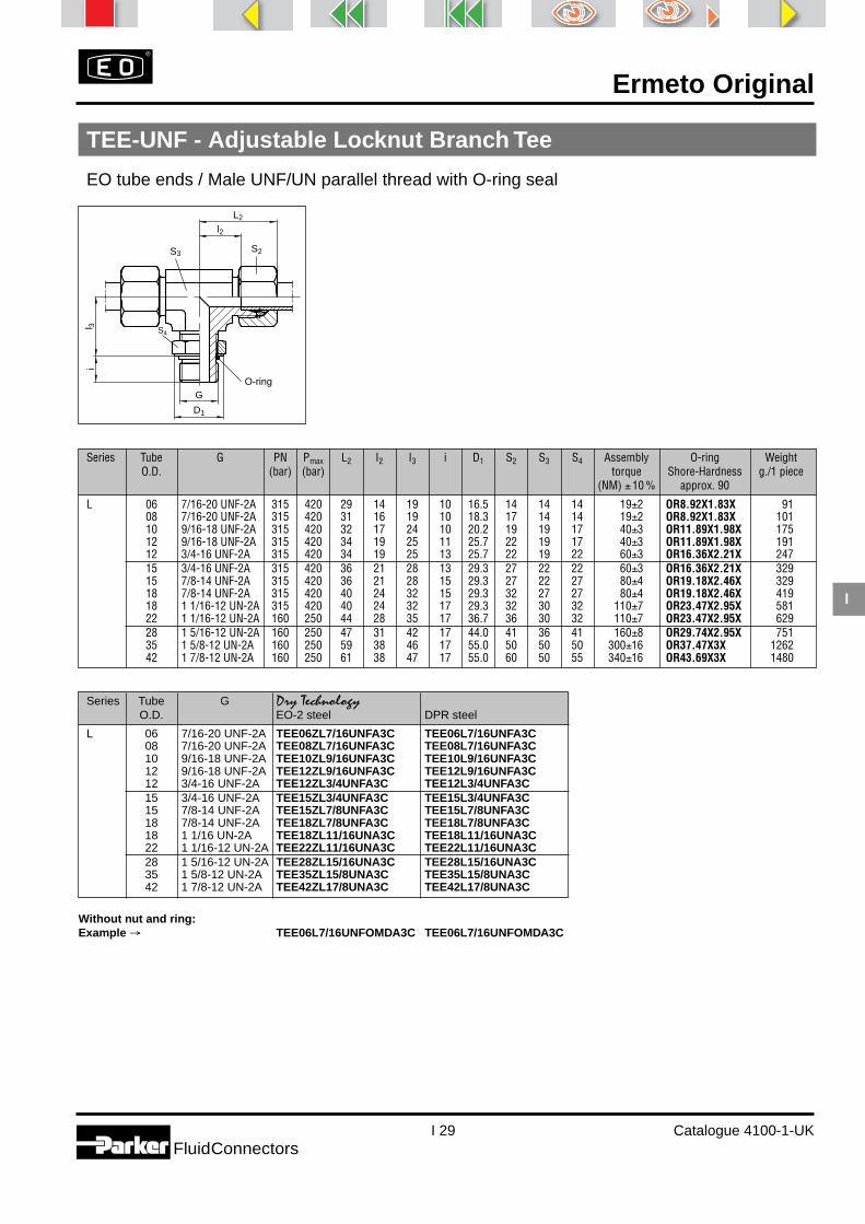
Ermeto Original
I 29 Catalogue 4100-1-UKFluidConnectors
I
Series Tube G Dry TechnologyO.D. EO-2 steel DPR steel
L 06 7/16-20 UNF-2A TEE06ZL7/16UNFA3C TEE06L7/16UNFA3C08 7/16-20 UNF-2A TEE08ZL7/16UNFA3C TEE08L7/16UNFA3C10 9/16-18 UNF-2A TEE10ZL9/16UNFA3C TEE10L9/16UNFA3C12 9/16-18 UNF-2A TEE12ZL9/16UNFA3C TEE12L9/16UNFA3C12 3/4-16 UNF-2A TEE12ZL3/4UNFA3C TEE12L3/4UNFA3C15 3/4-16 UNF-2A TEE15ZL3/4UNFA3C TEE15L3/4UNFA3C15 7/8-14 UNF-2A TEE15ZL7/8UNFA3C TEE15L7/8UNFA3C18 7/8-14 UNF-2A TEE18ZL7/8UNFA3C TEE18L7/8UNFA3C18 1 1/16 UN-2A TEE18ZL11/16UNA3C TEE18L11/16UNA3C22 1 1/16-12 UN-2A TEE22ZL11/16UNA3C TEE22L11/16UNA3C28 1 5/16-12 UN-2A TEE28ZL15/16UNA3C TEE28L15/16UNA3C35 1 5/8-12 UN-2A TEE35ZL15/8UNA3C TEE35L15/8UNA3C42 1 7/8-12 UN-2A TEE42ZL17/8UNA3C TEE42L17/8UNA3C
Without nut and ring:Example → TEE06L7/16UNFOMDA3C TEE06L7/16UNFOMDA3C
TEE-UNF - Adjustable Locknut Branch Tee
EO tube ends / Male UNF/UN parallel thread with O-ring seal
Series Tube G PN Pmax L2 I2 I3 i D1 S2 S3 S4 Assembly O-ring WeightO.D. (bar) (bar) torque Shore-Hardness g./1 piece
(NM) ±10 % approx. 90
L 06 7/16-20 UNF-2A 315 420 29 14 19 10 16.5 14 14 14 19±2 OR8.92X1.83X 9108 7/16-20 UNF-2A 315 420 31 16 19 10 18.3 17 14 14 19±2 OR8.92X1.83X 10110 9/16-18 UNF-2A 315 420 32 17 24 10 20.2 19 19 17 40±3 OR11.89X1.98X 17512 9/16-18 UNF-2A 315 420 34 19 25 11 25.7 22 19 17 40±3 OR11.89X1.98X 19112 3/4-16 UNF-2A 315 420 34 19 25 13 25.7 22 19 22 60±3 OR16.36X2.21X 24715 3/4-16 UNF-2A 315 420 36 21 28 13 29.3 27 22 22 60±3 OR16.36X2.21X 32915 7/8-14 UNF-2A 315 420 36 21 28 15 29.3 27 22 27 80±4 OR19.18X2.46X 32918 7/8-14 UNF-2A 315 420 40 24 32 15 29.3 32 27 27 80±4 OR19.18X2.46X 41918 1 1/16-12 UN-2A 315 420 40 24 32 17 29.3 32 30 32 110±7 OR23.47X2.95X 58122 1 1/16-12 UN-2A 160 250 44 28 35 17 36.7 36 30 32 110±7 OR23.47X2.95X 62928 1 5/16-12 UN-2A 160 250 47 31 42 17 44.0 41 36 41 160±8 OR29.74X2.95X 75135 1 5/8-12 UN-2A 160 250 59 38 46 17 55.0 50 50 50 300±16 OR37.47X3X 126242 1 7/8-12 UN-2A 160 250 61 38 47 17 55.0 60 50 55 340±16 OR43.69X3X 1480
D1
l2
L2
G
l 3i
S4
S3 S2
O-ring

Ermeto Original
I 30 Catalogue 4100-1-UKFluidConnectors
I
Series Tube G PN Pmax L2 I2 I3 i D1 S2 S3 S4 Assembly O-ring WeightO.D. (bar) (bar) torque Shore-Hardness g./1 piece
(NM) ±10 % approx. 90
L 06 7/16-20 UNF-2A 315 420 29 14 19 10 16.5 14 14 14 19±2 OR8.92X1.83X 9108 7/16-20 UNF-2A 315 420 31 16 19 10 18.3 17 14 14 19±2 OR8.92X1.83X 10110 9/16-18 UNF-2A 315 420 32 17 24 10 20.2 19 19 17 40±3 OR11.89X1.98X 17512 9/16-18 UNF-2A 315 420 34 19 25 11 25.7 22 19 17 40±3 OR11.89X1.98X 19112 3/4-16 UNF-2A 315 420 34 19 25 13 25.7 22 19 22 60±3 OR16.36X2.21X 24715 3/4-16 UNF-2A 315 420 36 21 28 13 29.3 27 22 22 60±3 OR16.36X2.21X 32915 7/8-14 UNF-2A 315 420 36 21 28 15 29.3 27 22 27 80±4 OR19.18X2.46X 32918 7/8-14 UNF-2A 315 420 40 24 32 15 29.3 32 27 27 80±4 OR19.18X2.46X 41918 1 1/16-12 UN-2A 315 420 40 24 32 17 29.3 32 30 32 110±7 OR23.47X2.95X 58122 1 1/16-12 UN-2A 160 250 44 28 35 17 36.7 36 30 32 110±7 OR23.47X2.95X 62928 1 5/16-12 UN-2A 160 250 47 31 42 17 44.0 41 36 41 160±8 OR29.74X2.95X 75135 1 5/8-12 UN-2A 160 250 59 38 46 17 55.0 50 50 50 300±16 OR37.47X3X 126242 1 7/8-12 UN-2A 160 250 61 38 47 17 55.0 60 50 55 340±16 OR43.69X3X 1430
LEE-UNF - Adjustable Locknut Run Tee
EO tube ends / Male UNF/UN parallel thread with O-ring seal
Series Tube G Dry TechnologyO.D. EO-2 steel DPR steel
L 06 7/16-20 UNF-2A LEE06ZL7/16UNFA3C LEE06L7/16UNFA3C08 7/16-20 UNF-2A LEE08ZL7/16UNFA3C LEE08L7/16UNFA3C10 9/16-18 UNF-2A LEE10ZL9/16UNFA3C LEE10L9/16UNFA3C12 9/16-18 UNF-2A LEE12ZL9/16UNFA3C LEE12L9/16UNFA3C12 3/4-16 UNF-2A LEE12ZL3/4UNFA3C LEE12L3/4UNFA3C15 3/4-16 UNF-2A LEE15ZL3/4UNFA3C LEE15L3/4UNFA3C15 7/8-14 UNF-2A LEE15ZL7/8UNFA3C LEE15L7/8UNFA3C18 7/8-14 UNF-2A LEE18ZL7/8UNFA3C LEE18L7/8UNFA3C18 1 1/16-12 UN-2A LEE18ZL11/16UNA3C LEE18L11/16UNA3C22 1 1/16-12 UN-2A LEE22ZL11/16UNA3C LEE22L11/16UNA3C28 1 5/16-12 UN-2A LEE28ZL15/16UNA3C LEE28L15/16UNA3C35 1 5/8-12 UN-2A LEE35ZL15/8UNA3C LEE35L15/8UNA3C42 1 7/8-12 UN-2A LEE42ZL17/8UNA3C LEE42L17/8UNA3C
Without nut and ring:Example → LEE06L7/16UNFOMDA3C LEE06L7/16UNFOMDA3C
D1
l2L2
G
L 2l 3
i
S4
S3
S2
O-ring

Ermeto Original
I 31 Catalogue 4100-1-UKFluidConnectors
I
Series Tube G PN Pmax L2 I2 I3 i D1 S2 S3 S4 Assembly O-ring WeightO.D. (bar) (bar) torque Shore-Hardness g./1 piece
(NM) ±10 % approx. 90
L 06 7/16-20 UNF-2A 315 420 24 9 19 10 16.5 14 14 14 19±2 OR8.92X1.83X 5708 7/16-20 UNF-2A 315 420 27 12 19 10 18.3 17 14 14 19±2 OR8.92X1.83X 6210 9/16-18 UNF-2A 315 420 27 12 24 10 20.2 19 19 17 40±3 OR11.89X1.98X 10512 9/16-18 UNF-2A 315 420 28 14 24 11 25.7 22 19 17 40±3 OR11.89X1.98X 10112 3/4-16 UNF-2A 315 420 28 14 24 13 25.7 22 19 22 60±3 OR16.36X2.21X 14715 3/4-16 UNF-2A 315 420 32 17 24 13 29.3 27 22 22 60±3 OR16.36X2.21X 20315 7/8-14 UNF-2A 315 420 32 17 24 15 29.3 27 22 27 80±4 OR19.18X2.46X 18018 7/8-14 UNF-2A 315 420 33 17 30 15 29.3 32 27 27 80±4 OR19.18X2.46X 26418 1 1/16-12 UN-2A 315 420 33 17 30 17 29.3 32 30 32 110±7 OR23.47X2.95X 36422 1 1/16-12 UN-2A 160 250 35 19 33 17 36.7 36 30 32 110±7 OR23.47X2.95X 38828 1 5/16-12 UN-2A 160 250 39 23 35 17 44.0 41 36 41 160±8 OR29.74X2.95X 50035 1 5/8-12 UN-2A 160 250 48 27 37 17 55.0 50 50 50 300±16 OR37.47X3X 73142 1 7/8-12 UN-2A 160 250 49 26 37 17 55.0 60 50 55 340±16 OR43.69X3X 815
VEE-UNF - Adjustable Locknut 45° Elbow
EO tube end / Male UNF/UN parallel thread with O-ring seal
Series Tube G Dry TechnologyO.D. EO-2 steel DPR steel
L 06 7/16-20 UNF-2A VEE06ZL7/16UNFA3C VEE06L7/16UNFA3C08 7/16-20 UNF-2A VEE08ZL7/16UNFA3C VEE08L7/16UNFA3C10 9/16-18 UNF-2A VEE10ZL9/16UNFA3C VEE10L7/16UNFA3C12 9/16-18 UNF-2A VEE12ZL9/16UNFA3C VEE12L9/16UNFA3C12 3/4-16 UNF-2A VEE12ZL3/4UNFA3C VEE12L3/4UNFA3C15 3/4-16 UNF-2A VEE15ZL3/4UNFA3C VEE15L3/4UNFA3C15 7/8-14 UNF-2A VEE15ZL7/8UNFA3C VEE15L7/8UNFA3C18 7/8-14 UNF-2A VEE18ZL7/8UNFA3C VEE18L7/8UNFA3C18 1 1/16-12 UN-2A VEE18ZL11/16UNA3C VEE18L11/16UNA3C22 1 1/16-12 UN-2A VEE22ZL11/16UNA3C VEE22L11/16UNA3C28 1 5/16-12 UN-2A VEE28ZL15/16UNA3C VEE28L15/16UNA3C35 1 5/8-12 UN-2A VEE35ZL15/8UNA3C VEE35L15/8UNA3C42 1 7/8-12 UN-2A VEE42ZL17/8UNA3C VEE42L17/8UNA3C
Without nut and ring:Example → VEE06L7/16UNFOMDA3C VEE06L7/16UNFOMDA3C
D1
l 2
L 2
G
l 3i
S4
S3
S 2
45°
O-ring

Ermeto Original
I 32 Catalogue 4100-1-UKFluidConnectors
I
FM - EO-2 Functional Nut
24°
i1d 5d 3d 4MM
t1h1
d 3
S2
Series Tube DN M d3 d4 d5 t1 i1 S2 h1 WeightO.D. Size metric thread g./1 piece
LL 04 04 M 8×1 4 5.0 3.0 4.0 8 10 11.0 506 06 M 10×1 6 7.5 4.5 5.5 8 12 11.5 6
L 06 04 M 12×1.5 6 8.1 4.0 7.0 10 14 15.0 1208 06 M 14×1.5 8 10.1 6.0 7.0 10 17 15.0 1710 08 M 16×1.5 10 12.3 8.0 7.0 11 19 16.0 2212 10 M 18×1.5 12 14.3 10.0 7.0 11 22 16.0 3015 12 M 22×1.5 15 17.3 12.0 7.0 12 27 17.5 4818 16 M 26×1.5 18 20.3 15.0 7.5 12 32 18.5 7022 20 M 30×2 22 24.3 19.0 7.5 14 36 20.5 9428 25 M 36×2 28 30.3 24.0 7.5 14 41 21.0 10635 32 M 45×2 35 38.0 30.0 10.5 16 50 24.0 16042 40 M 52×2 42 45.0 36.0 11.0 16 60 24.0 244

Ermeto Original
I 33 Catalogue 4100-1-UKFluidConnectors
I
FM - EO-2 Functional Nut
24°
i1d 5d 3d 4MM
t1h1
d 3
S2
Series Tube Dry TechnologyO.D. Dry Technology Dry Technology Steel NBR with
Steel/NBR Stainless steel/FPM stainless steel cutting ring
LL 04 FM04LLA3C FM04LLSSA06 FM06LLA3C FM06LLSSA
L 06 FM06LA3C FM06L71 FM06LSSA08 FM08LA3C FM08L71 FM08LSSA10 FM10LA3C FM10L71 FM10LSSA12 FM12LA3C FM12L71 FM12LSSA15 FM15LA3C FM15L71 FM15LSSA18 FM18LA3C FM18L71 FM18LSSA22 FM22LA3C FM22L71 FM22LSSA28 FM28LA3C FM28L71 FM28LSSA35 FM35LA3C FM35L71 FM35LSSA42 FM42LA3C FM42L71 FM42LSSA

Ermeto Original
I 34 Catalogue 4100-1-UKFluidConnectors
I
Series Tube DN M d3 d4 d5 t1 i1 S2 h1 L L1 WeightO.D. Size metric g./1 piece
thread M DPR (D)
LL 04 03 M 8×1 4 5.0 3 4.0 8 10 11.0 - 6.0 4 0.306 04 M 10×1 6 7.5 4 5.5 8 12 11.5 - 7.0 6 0.808 06 M 12×1 8 9.5 6 5.5 9 14 12.0 - 7.0 7 1.010 08 M 14×1 10 11.5 8 5.5 9 17 12.5 - 7.0 11 1.312 10 M 16×1 12 13.5 10 6.0 9 19 13.0 - 7.5 13 1.6
L 06 04 M 12×1.5 6 8.1 4 7.0 10 14 15.0 9.5 9.5 10 1.708 06 M 14×1.5 8 10.1 6 7.0 10 17 15.0 9.5 9.0 15 2.210 08 M 16×1.5 10 12.3 8 7.0 11 19 16.0 10.5 10.0 18 3.112 10 M 18×1.5 12 14.3 10 7.0 11 22 16.0 10.0 10.0 25 3.515 12 M 22×1.5 15 17.3 12 7.0 12 27 17.5 10.0 10.0 42 4.318 16 M 26×1.5 18 20.3 15 7.5 12 32 18.5 10.0 10.0 62 5.522 20 M 30×2 22 24.3 19 7.5 14 36 20.5 10.5 10.5 82 7.328 25 M 36×2 28 30.3 24 7.5 14 41 21.0 10.5 10.5 89 9.435 32 M 45×2 35 38.0 30 10.5 16 50 24.0 13.5 13.0 137 20.042 40 M 52×2 42 45.0 36 11.0 16 60 24.0 13.5 13.5 216 23.0
M Nut - DPR Progressive ring - D Cutting ring
i1
d 5d 3d 4
M
24°M
t1
h1
S2
L
d 3
d 3
d 3Progressive ring: DPR
Cutting ring: D
Nut: M
L1

Ermeto Original
I 35 Catalogue 4100-1-UKFluidConnectors
I
DPR (D)Steel Stainless steel brass
D04LLX D04LL71X D04LLMSXD06LLX D06LL71X D06LLMSXD08LLX D08LL71X D08LLMSXD10LLX D10LL71X D10LLMSXD12LLX D12LL71X D12LLMSXDPR06LX DPR06L71X D06LMSXDPR08LX DPR08L71X D08LMSXDPR10LX DPR10L71X D10LMSXDPR12LX DPR12L71X D12LMSXDPR15LX DPR15L71X D15LMSXDPR18LX DPR18L71X D18LMSXDPR22LX DPR22L71X D22LMSXDPR28LX DPR28L71X D28LMSXDPR35LX DPR35L71X D35LMSXDPR42LX DPR42L71X D42LMSX
Series Tube MO.D. Steel Stainless steel brass
LL 04 M04LLA3CX M04LL71X M04LLMSX06 M06LLA3CX M06LL71X M06LLMSX08 M08LLA3CX M08LL71X M08LLMSX10 M10LLA3CX M10LL71X M10LLMSX12 M12LLA3CX M12LL71X M12LLMSX
L 06 M06LA3CX M06LEODURX M06LMSX08 M08LA3CX M08LEODURX M08LMSX10 M10LA3CX M10LEODURX M10LMSX12 M12LA3CX M12LEODURX M12LMSX15 M15LA3CX M15LEODURX M15LMSX18 M18LA3CX M18LEODURX M18LMSX22 M22LA3CX M22LEODURX M22LMSX28 M28LA3CX M28LEODURX M28LMSX35 M35LA3CX M35LEODURX M35LMSX42 M42LA3CX M42LEODURX M42LMSX
M Nut - DPR Progressive ring - D Cutting ring
i1
d 5d 3d 4
M
24°M
t1
h1
S2
L
d 3
d 3
d 3Progressive ring: DPR
Cutting ring: D
Nut: M
L1

Ermeto Original
I 36 Catalogue 4100-1-UKFluidConnectors
I
GM - Bulkhead locknut
Series Tube SW M h WeightO.D. metric thread g./1 piece
L 06 17 M 12×1.5 6 708 19 M 14×1.5 6 810 22 M 16×1.5 6 1112 24 M 18×1.5 6 1215 30 M 22×1.5 7 2318 36 M 26×1.5 8 3722 41 M 30×2 8 4628 46 M 36×2 9 5835 55 M 45×2 9 7142 65 M 52×2 10 123
h
SW
M
Series TubeO.D. Steel Stainless steel Brass
L 06 GM06LA3CX GM06L71X GM06LMSX08 GM08LA3CX GM08L71X GM08LMSX10 GM10LA3CX GM10L71X GM10LMSX12 GM12LA3CX GM12L71X GM12LMSX15 GM15LA3CX GM15L71X GM15LMSX18 GM18LA3CX GM18L71X GM18LMSX22 GM22LA3CX GM22L71X GM22LMSX28 GM28LA3CX GM28L71X GM28LMSX35 GM35LA3CX GM35L71X GM35LMSX42 GM42LA3CX GM42L71X GM42LMSX

Ermeto Original
I 37 Catalogue 4100-1-UKFluidConnectors
I
Series Tube PN Pmax L O-ring WeightO.D. (bar) (bar) Shore-Hardness g./1 piece
approx. 90
L 06 315 500 18.5 OR4.5X1.5X 608 315 500 18.5 OR6.5X1.5X 910 315 500 20.0 OR8X1.5X 1512 315 400 20.5 OR10X1.5X 2115 315 400 20.5 OR12X2X 3218 315 400 22.5 OR15X2X 4922 160 250 25.0 OR20X2X 8028 160 250 25.5 OR26X2X 13135 160 250 30.0 OR32X2.5X 24042 160 250 30.0 OR38X2.5X 343
O-ring FPM:Example → OR4.5X1.5VITX
VKA - Blanking plug for cones
Series Tube Dry Technology Dry TechnologyO.D. Steel/NBR Stainless steel/FPM Brass/NBR
L 06 VKA06A3C VKA0671 VKA06MS08 VKA08A3C VKA0871 VKA08MS10 VKA10A3C VKA1071 VKA10MS12 VKA12A3C VKA1271 VKA12MS15 VKA15A3C VKA1571 VKA15MS18 VKA18A3C VKA1871 VKA18MS22 VKA22A3C VKA2271 VKA22MS28 VKA28A3C VKA2871 VKA28MS35 VKA35A3C VKA3571 VKA35MS42 VKA42A3C VKA4271 VKA42MS
Tube
O.D
.
LO-Ring

Ermeto Original
I 38 Catalogue 4100-1-UKFluidConnectors
I
Male metric Male stud PN Pmax D L i S6 Weight Dry Technology Steel Dry Technology Stainless steelparallel BSP (bar) (bar) g./1 piece Metric parallel BSPP Metric parallel BSPP
thread G thread G
M 10 × 1 G 1/8 A 400 500 14.0 12.0 8.0 5 8 VSTI10X1EDA3C VSTI1/8EDA3C VSTI10X1ED71 VSTI1/8ED71M 12 × 1.5 400 500 17.0 17.0 12.0 6 14 VSTI12X1.5EDA3C VSTI12X1.5ED71M 14 × 1.5 G 1/4 A 400 500 19.0 17.0 12.0 6 20 VSTI14X1.5EDA3C VSTI1/4EDA3C VSTI14X1.5ED71 VSTI1/4ED71M 16 × 1.5 G 3/8 A 400 500 22.0 17.0 12.0 8 25 VSTI16X1.5EDA3C VSTI3/8EDA3C VSTI16X1.5ED71 VSTI3/8ED71M 18 × 1.5 400 500 23.9 17.0 12.0 8 32 VSTI18X1.5EDA3C VSTI18X1.5ED71M 20 × 1.5 400 500 25.9 19.0 14.0 10 42 VSTI20X1.5EDA3C VSTI20X1.5ED71M 22 × 1.5 G 1/2 A 400 500 27.0 19.0 14.0 10 51 VSTI22X1.5EDA3C VSTI1/2EDA3C VSTI22X1.5ED71 VSTI1/2ED71M 26 × 1.5 400 500 31.9 21.0 16.0 12 78 VSTI26X1.5EDA3C VSTI26X1.5ED71M 27 × 2 G 3/4 A 400 500 32.0 21.0 16.0 12 79 VSTI27X2EDA3C VSTI3/4EDA3C VSTI27X2ED71 VSTI3/4ED71M 33 × 2 G 1 A 400 500 39.9 22.5 16.0 17 130 VSTI33X2EDA3C VSTI1EDA3C VSTI33X2ED71 VSTI1ED71M 42 × 2 G 11/4 A 315 400 49.9 22.5 16.0 22 198 VSTI42X2EDA3C VSTI11/4EDA3C VSTI42X2ED71 VSTI11/4ED71M 48 × 2 G 11/2 A 315 400 55.0 22.5 16.0 24 263 VSTI48X2EDA3C VSTI11/2EDA3C VSTI48X2ED71 VSTI11/2ED71
VSTI R/M-ED - Blanking plug for ports
BSPP or Metric parallel thread with Eolastic sealing ED
Eolastic - sealing
L
i
D G
S6

Ermeto Original
I 39 Catalogue 4100-1-UKFluidConnectors
I
Tube ID D d d1 L WeightO.D. g./1 piece Brass
04 2.0 3.5 2.0 1.3 8 1 E04/02X04 2.5 4.0 2.5 1.7 8 1 E04/2.5X05 3.0 5.0 3.0 2.2 14 1 E0506/03X06 3.0 5.0 3.0 2.2 14 1 E0506/03X05 4.0 5.0 4.0 3.2 14 1 E0506/04X06 4.0 5.0 4.0 3.2 14 1 E0506/04X08 4.0 6.6 4.0 3.2 14 1 E08/04X06 5.0 6.0 5.0 4.0 14 1 E06/05X08 5.0 8.0 5.0 4.0 14 1 E08/05X10 6.0 8.0 6.0 5.0 15 1 E0810/06X08 6.0 8.0 6.0 5.0 15 1 E0810/06X10 8.0 10.0 8.0 6.7 15 1 E10/08X12 8.0 12.0 8.0 6.7 15 2 E12/08X12 9.0 12.0 9.0 7.7 15 2 E12/09X12 10.0 12.0 10.0 8.7 15 2 E1215/10X15 12.0 14.8 12.0 10.7 15 3 E15/12X15 12.5 14.8 12.5 11.2 15 3 E1516/12.5X16 12.5 14.8 12.5 11.2 15 3 E1516/12.5X18 14.0 17.8 14.0 12.7 15 4 E18/14X18 16.0 17.8 16.0 14.7 20 4 E1820/16X20 16.0 17.8 16.0 14.7 20 4 E1820/16X22 18.0 21.8 18.0 16.7 16 5 E22/18X
E - Tube insert
for plastic tubing
D d
d 1
L

Ermeto Original
I 40 Catalogue 4100-1-UK
FluidConnectors
SensoControl®
The Serviceman for fluid systems
Hand-held measuring device to measure pressure, temperature, flow and rotational speed
■ Easy operation
■ Rugged design
■ Compact dimensions
■ Large display
■ Units of measurement displayed
■ Differential value measurement
■ MIN/MAX Memory
■ Hold function
■ 2 inputs with sensor recognition
■ Low power consumption
■ Data output for printer and PC
■ External power supply
The SERVICEMAN SCM-150 fromParker is a modern measuring systemand real alternative to conventionalmechanical pressure measurement influid systems.
The device can be used wherever fluidcontrol and components are in use.The SCM-150 is very tough and insen-sitive to dirt so that it can be used inextreme conditions. It can be carriedby hand or used as a desktop unit withan integrated stand. Operation is veryeasy.
Everything is controlled by 8 buttons.2 sensors inputs are provided, thusenables differential measurements.
A dynamic maximum and minimumvalue memory and a display “hold”function have also been implemented.
The Serviceman identifies the type ofconnected sensors and its properunits (bar; l/min; PPM; °C).
Therefore wrong measurements andtime consuming adjustments are thusavoided.
A printer can also be used to docu-ment the most important fluid param-eters.
Following a pre-set transmission inter-val of between 1 and 100 sec., the de-vice automatically documents themaximum, minimum and current val-ues for the system.
The memory is deleted after print-ing. This permits a precise determina-tion of the extreme values per ma-chine cycle. The device can be con-
nected to any PC with an auxiliary PCadapter.
Thus, the drafting of status reports toverify data (ISO 9000) poses no prob-lems.
The Serviceman SCM-150 will be ofinterest to all maintenance engineersworking with mobile hydraulic sys-tems, in the construction, machineryand equipment sector, environmentalengineering, ship-building and off-shore.
The Serviceman has been developedto give an excellent range of functionsand benefits, at a modest price.
I

Ermeto Original
I 41 Catalogue 4100-1-UK
FluidConnectors
� 4-digit LCD to display units, input status and battery status
� RESET to delete MIN/MAX Readings
� On/Off switch
� Maximum value display RESET must be pressed before startof measurement
� Channel selection input 1/2
� Differential value Input 1 minus Input 2
� Minimum value display RESET must be pressed before thestart of measurements
� Printout of actual/max/min values in numerical form
Hold function for display values
2 sensor inputs
� Socket for external power supply (SCM-150-1-02)
� Data output (SCM-150-1-02)
Data transmission to printer SCPR-100 or PC with SCDA-150adaptor.
Technical Data
● Inputs2 inputs with sensor-recognition(p, T, Q, n)
Resolution12 Bit = 4.096 steps
Scanning rate= < 2 ms
● Display– LCD text display (4-digit)– Character height: 13 mm– Accuracy: < 0.3% ± 2 digits– Display of units:
bar, PSI, L/min., USGPM, °C, °F,U/min., RPM, %
EMC compatibility pursuant to:
– Interference emission DIN/EN 50081 Part 1 (VDE 0839 Part 81-1)– Interference emission DIN/EN 50081 Part 1 (VDE 0839 Part 81-1)
Functional description SCM-150
● Functions– Diffential value measurement
MIN/MAX memory– Hold function– Autoprint function (SCM-150-1-02)– Battery level display LO BAT– Auto power off after 15 min.
● Data-Output SCM-150-1-02– Infrared interface (RS232C)
to thermoprinter SCPR-100 or PC(only in combination withSCDA-150)
● Ambient conditions– Temperature range: 0–50°C– Storage temperature: –20…+60°C– Rel. humidity: <85 %– Protection level: IP54 (EN 60529)
● Power supplySCM-150-1-01– 9V battery (IEC 6F 22)– Approx. 5 h operation with one
sensorSCM-150-1-02– NC storage battery, 9V– Approx. 5 h operation with one
sensor– Battery charge circuit– External power supply with SCSN-350
● GeneralHousing material– Plastic housing of ABS– Protective covering of rubber and
carrying straps
DimensionsL/W/H 145×70×40 mm
WeightApprox. 340 g.
� �
�
�
�
�
�
�
�
�
I

Ermeto Original
I 42 Catalogue 4100-1-UK
FluidConnectors
Fluid System
T
DisplaySCP-1000-72-08
DisplaySCP-100-72-08
DisplaySCP-015-72-08
Diagnostic-Adapter (M16x2)
SCP-XXX-72-08
SCA-1/2-EMA-3
SCT-150-74-08
SCA-GMA3/20S/T
SCK-102-02-08
Q
Flow turbineSCFT-XXX-01-02
SCK-102-02-08
Serviceman
For further details,please look at bulletin 4051.
Q
PC-Software
PC-Adapter PC-ConnectingCable
SCK-700-00-29
SCK-700-00-29
SC PR100
SC SN350
SC SN100
I

Ermeto Original
I 43 Catalogue 4100-1-UK
FluidConnectors
Description Part no …
Handmeter SCM-150 to measure p, T, Q, n SCM-150-1-01also with data output an external SCM-150-1-02power supply
Pressure sensor SCP with fixed cable connection for direct connectionto the SCM-150 SCP- . . . . -72-08
Measuring range -1… 15 bar 0150 … 100 bar 1000 … 1000 bar 1000
Flow sensor SCQ further information on data sheet 4069
Flow turbine SCFT complete with measuring points for pressure andtemperature, signal converter with voltage output SCFT- . . . -01-02For details please see data sheet 4068
Measuring range 1.0 … 15 l/min 0157.5 … 60 l/min 06015 … 300 l/min 30025 … 600 l/min 600
Temperature measurement measuring range –25 … +125°C SCT-150-74-08
Rotational speed recording measuring range 0 … 10000 rpm SCRPM-210
Connecting cable, 2 m connection sensor/handmeter SCK-102-02-08
Accessories for SCM-150
Measuring case for handmeter, pressure sensors, adapters SC-500charger and batteryalso for printer and flow sensors SCC-550
Printer SCPR thermoprinter for connection to SCM-150-1-02 SCPR-100-1-01Printer cable, 1 m optical transmission SCK-700-00-29PC adapter to transfer data to a PC SCDA-150
Charger to charge NiCD storage battery SC-811 SC-800NiCD storage battery 9V/110mAh (IEC 6F 22) SC-811Mains adapter SCSN power supply for SCM-150-1-02 SCSN-350
power supply for SCM, SCPR, SCDA-150 SCSN-345
Car cable, 5 m connection between car socket – SCM-150-1-02 SCK-519-05-21/A
Calibration certificate for SCM-150 according to DIN ISO 9001/EN 29009
Order code
I

Brass adaptorsBrass adaptorsfor heavy dutyapplications
Catalogue 4360-UK

Brass adaptors
J 2 Catalogue 4360-UKFluidConnectors
J

Brass adaptors
J 3 Catalogue 4360-UKFluidConnectors
J
IndexPipe nipples
equalBSPTFF33 - p. J 5
Bulkheadunions
Pipeconnectors
equalBSPPGG44 - p. J 8
90° elbows
equal femaleBSPPDD44 - p. J 9
Tees
Cross
equal femaleBSPPMMO444 - p. J 10
equal femaleBSPPKMMOO4 - p. J 10
Plugs
Reducers
male branch teeBSPP-BSPP-BSPTMMS443 - p. J 10
male run teeBSPP-BSPT-BSPPMRO434 - p. J 10
male-femaleBSPT-BSPPCD43 - p. J 9
Conversionadaptors
pipe threadreducer male-femaleNPTFPTR - p. J 7
pipe threadreducer male-femaleNPTF209P - p. J 7
female -BSPPWGG44 - p. J 9
female -NPTF207ACBH - p. J 9
hex headBSPTHP3 - p. J 11
hollow hexNPTFHHP - p. J 12
hollow hexNPTF219P - p. J 12
equalNPTFFF - p. J 5
equalNPTF216P - p. J 5
equalBSPPFF44 - p. J 5
unequalBSPTFF33 - p. J 5
reducing connectorfemale-maleNPTFFG - p. J 6
reducing connectorfemale-maleNPTF222P - p. J 6
pipe threadreducer male-femaleBSPT-BSPPPTR34 - p. J 6
equalNPTFGG - p. J 8
equalNPTF207P - p. J 8
unequalBSPPGG44 - p. J 8
hex headNPTFHP - p. J 11
hex headNPTF218P - p. J 11
hollow hexBSPTHHP3 - p. J 11
male NPT - femaleBSPPFHG4 - p. J 12
reducing connectorfemale-maleBSPP-BSPTFG43 - p. J 6

Brass adaptors
J 4 Catalogue 4360-UKFluidConnectors
J
Advantages
To simplify the installation of pneumatic systems, Parker supplies acomprehensive range of adaptors for BSPP, BSPT and NPT pipethreads. The range includes pipe nipples, pipe connectors, reducers,bulkhead female unions, elbows, tees, crosses and hex head plugs.
Technical features
Brass From - 60°Cto + 190°C
60 barexcept where indicated
Brass forgings
The hot forging process increases thedensity of the material, refines thegrain structure and improves materialstrength.
Parker brass adaptors are produced from hot forgings to meet exactingtolerances.
Packaging
Parker brass adaptors are packagedin biodegradable plastic bagspreventing thread damage andensuring a quality adaptor.
Working temperatureMaterial Working pressure

Brass adaptors
J 5 Catalogue 4360-UKFluidConnectors
J
* Inch dimensions
* Inch dimensions
Workingpressure
(bar)
These parts are supplied with two copper seals.
A Part number C L P Weightg.
1/8 1/8FF33B 10 19 8 71/4 1/4FF33B 14 27 11 163/8 3/8FF33B 17 28 12 251/2 1/2FF33B 22 36 15 503/4 3/4FF33B 27 40 16 90
1 1FF33B 36 46 19 151
FF33 - Pipe nipple - BSPT
C
AA
L
P P
A Part number C* L P Weightin mm g.
1/8 1/8FFB 7/16 11.2 27 10 10 2601/4 1/4FFB 5/8 15.9 37 14 31 2603/8 3/8FFB 3/4 19.5 37 14 38 2601/2 1/2FFB 7/8 22.3 48 19 70 260
FF - Pipe nipple - NPTF - Heavy series
C
AA
L
P P
A Part number C* L P Weightin mm g.
1/8 216P-2 7/16 11.2 25 10 81/4 216P-4 9/16 14.3 35 14 253/8 216P-6 11/16 17.5 36 14 291/2 216P-8 7/8 22.3 46 19 64
216P - Pipe nipple - NPTF
C
AA
L
P P
FF33 - Unequal pipe nipple - BSPT
A1 A2 Part number C L P1 P2 Weightg.
1/8 1/4 1/8x1/4FF33B 14 23 8 11 161/8 3/8 1/8x3/8FF33B 17 24 8 12 241/8 1/2 1/8x1/2FF33B 22 28 8 15 401/4 3/8 1/4x3/8FF33B 17 28 11 12 281/4 1/2 1/4x1/2FF33B 22 31 11 15 41
3/8 1/2 3/8x1/2FF33B 22 32 12 15 563/8 3/4 3/8x3/4FF33B 27 35 12 16 921/2 3/4 1/2x3/4FF33B 27 38 15 16 363/4 1 3/4x1FF33B 36 43 16 19 205
C
A2A1
L
P1 P2
B Part number C J L T Weightg.
1/8 1/8FF44B 14 6 19 8 181/4 1/4FF44B 17 7 22 9 223/8 3/8FF44B 22 8 24 9 401/2 1/2FF44B 27 10 31 11 77
FF44 - Pipe nipple - BSPP
C
B
L
TJ J
B

Brass adaptors
J 6 Catalogue 4360-UKFluidConnectors
J
For product availability please consult our price list 0093-UK.Dimensions shown may be changed at any time without prior notice.
* Inch dimensions
* Inch dimensions
Workingpressure
(bar)
FG - Reducing connector female-male - NPTF - Heavy series
C
A2
L
P2
P1
A1
FG43 - Reducing connector female-male - BSPP-BSPT
A B Part number C J L P Weightg.
1/8 1/4 1/4x1/8FG43B 17 11 21.5 6.5 201/8 3/8 3/8x1/8FG43B 22 12 25.0 7.5 351/4 3/8 3/8x1/4FG43B 22 12 28.0 11.0 401/8 1/2 1/2x1/8FG43B 27 15 28.0 6.5 631/4 1/2 1/2x1/4FG43B 27 15 30.0 10.0 71
3/8 1/2 1/2x3/8FG43B 27 15 28.6 10.0 661/2 3/4 3/4x1/2FG43B 32 16 39.0 15.0 1123/4 1 1x3/4FG43B 41 18 38.0 16.0 166
C
AB
L
P
J
222P - Reducing connector female-male - NPTF
A1 A2 Part number C* L P1 P2 Weightin mm g.
1/4 1/8 222P-4-2 3/4 19.5 27 14 10 323/8 1/4 222P-6-4 7/8 22.3 32 15 14 461/2 3/8 222P-8-6 1.1/16 27.0 37 19 14 83
C
A2
L
P2
P1
A1
PTR34 - Pipe thread reducer male-female - BSPT-BSPP
C
BA
L
P
J
A B Part number C J L P Weightg.
1/4 1/8 1/4x1/8PTR34B 14 8 16.0 11.0 103/8 1/8 3/8x1/8PTR34B 17 8 16.5 11.5 213/8 1/4 3/8x1/4PTR34B 17 11 14.6 10.0 141/2 1/8 1/2x1/8PTR34B 22 8 21.5 15.0 371/2 1/4 1/2x1/4PTR34B 22 11 18.3 12.5 42
1/2 3/8 1/2x3/8PTR34B 22 12 21.5 15.0 283/4 3/8 3/4x3/8PTR34B 27 12 23.0 16.0 683/4 1/2 3/4x1/2PTR34B 27 15 19.5 14.0 481 1/2 1x1/2PTR34B 36 15 23.6 17.0 1361 3/4 1x3/4PTR34B 36 16 27.0 19.0 90
A1 A2 Part number C* L P1 P2 Weightin mm g.
1/4 1/8 1/4x1/8FGB 3/4 19,5 31 14 10 32 263/8 1/4 3/8x1/4FGB 7/8 22,3 37 15 14 52 261/2 3/8 1/2x3/8FGB 1,1/8 28,6 43 19 14 94 22

Brass adaptors
J 7 Catalogue 4360-UKFluidConnectors
J
For product availability please consult our price list 0093-UK.Dimensions shown may be changed at any time without prior notice.
Workingpressure
(bar)
* Inch dimensions
* Inch dimensions
PTR - Pipe thread reducer male-female - NPTF - Heavy series
A1 A2 Part number C* L P1 P2 Weightin mm g.
1/4 1/8 1/4x1/8PTRB 5/8 15.9 22 11 8 21 2603/8 1/8 3/8x1/8PTRB 3/4 19.5 22 11 8 32 2603/8 1/4 3/8x1/4PTRB 3/4 19.5 22 12 8 28 2601/2 1/4 1/2x1/4PTRB 7/8 22.3 28 16 13 54 2201/2 3/8 1/2x3/8PTRB 7/8 22.3 28 15 13 43 220
3/4 3/8 3/4x3/8PTRB 1.1/8 28.6 30 16 14 81 1803/4 1/2 3/4x1/2PTRB 1.1/8 28.6 30 19 17 78 180
C
A1 A2
L
P1
P2
209P - Pipe thread reducer male-female - NPTF
A1 A2 Part number C* L P1 P2 Weightin mm g.
1/4 1/8 209P-4-2 9/16 14.3 19 11 8 123/8 1/8 209P-6-2 11/16 17.5 18 11 8 253/8 1/4 209P-6-4 11/16 17.5 19 12 8 171/2 1/4 209P-8-4 7/8 22.3 26 16 13 491/2 3/8 209P-8-6 7/8 22.3 26 15 13 33
3/4 3/8 209P-12-6 1.1/8 28.6 26 16 14 743/4 1/2 209P-12-8 1.1/8 28.6 26 19 17 57
C
A1 A2
L
P1
P2

Brass adaptors
J 8 Catalogue 4360-UKFluidConnectors
J
For product availability please consult our price list 0093-UK.Dimensions shown may be changed at any time without prior notice.
* Inch dimensions
* Inch dimensions
Workingpressure
(bar)
L
C
A A
P P
A Part number C* L P Weightin mm g.
1/8 1/8GGB 5/8 15.9 19 9 21 2601/4 1/4GGB 3/4 19.5 29 14 46 2603/8 3/8GGB 7/8 22.3 29 14 60 2601/2 1/2GGB 1.1/8 28.6 38 18 99 220
GG - Pipe connector - NPTF - Heavy series
C
A
L
P P
A
B Part number C J L Weightg.
1/8 1/8GG44B 14 8 16 131/4 1/4GG44B 17 10 20 213/8 3/8GG44B 22 12 24 281/2 1/2GG44B 27 14 28 653/4 3/4GG44B 32 16 32 99
1 1GG44B 41 18 36 194
GG44 - Pipe connector - BSPP
C
BB
L
J J
A Part number C* L P Weightin mm g.
1/8 207P-2 9/16 14.3 19 9 171/4 207P-4 3/4 19.5 28 14 403/8 207P-6 7/8 22.3 28 14 541/2 207P-8 1.1/16 27.0 38 18 88
207P - Pipe connector - NPTF
GG44 - Unequal pipe connector - BSPP
B1 B2 Part number C J1 J2 L Weightg.
1/8 1/4 1/8x1/4GG44B 17 8 10 18 231/8 3/8 1/8x3/8GG44B 22 8 12 20 451/8 1/2 1/8x1/2GG44B 27 8 14 22 751/4 3/8 1/4x3/8GG44B 22 10 12 22 461/4 1/2 1/4x1/2GG44B 27 10 14 24 793/8 1/2 3/8x1/2GG44B 17 12 14 26 68
C
B2B1
L
J1 J2

Brass adaptors
J 9 Catalogue 4360-UKFluidConnectors
J
For product availability please consult our price list 0093-UK.Dimensions shown may be changed at any time without prior notice.
* Inch dimensions
A Part number B1 C C4 L P T T1 W Weightg.
1/8 207ACBH-2 5/8-18 7/8* 15/16* 38 10.0 7 8 20 721/4 207ACBH-4 3/4-16 1* 1.1/8* 38 14.0 7 10 18 1003/8 207ACBH-6 1-14 1.1/8* 1.1/4* 34 15.0 7 10 13 1281/2 207ACBH-8 1.1/8-14 1.1/4* 1.3/8* 38 19.0 7 12 16 1593/4 207ACBH-M34 M34x1.5 41 41 39 17.5 10 8 19 214
1 207ACBH-M45 M45x2 55 58 46 20.5 13 11 19 553C4C
B1
WT
P P
T1
L
A A
207ACBH - Bulkhead female union - NPTF
B Part number B1 C C4 L T T1 W Weightg.
1/8 1/8WGG44B M16x1.5 19 22 22 5 5 12 341/4 1/4WGG44B M20x1.5 24 24 22 5 5 12 463/8 3/8WGG44B M23x1.5 27 27 24 6 6 12 581/2 1/2WGG44B M27x1.5 32 32 28 7 7 14 873/4 3/4WGG44B M34x1.5 41 41 31 8 10 13 1721 1WGG44B M45x2 55 55 36 11 13 12 453
C4C
B1
WT T1
B
L
WGG44 - Bulkhead female union - BSPP
B Part number C J M Weightg.
1/8 1/8DD44B 14 8 15 161/4 1/4DD44B 17 10 18 113/8 3/8DD44B 22 12 22 641/2 1/2DD44B 27 14 29 128
DD44 - 90° female pipe elbow - BSPP
C
JM
B
A B Part number C J M N P Y Weightg.
1/8 1/8 1/8CD43B 14 8 14 19.5 8 10 191/4 1/4 1/4CD43B 17 10 18 25.0 11 10 93/8 3/8 3/8CD43B 22 12 19 29.0 12 16 651/2 1/2 1/2CD43B 27 14 24 37.0 15 19 93
CD43 - 90° elbow male-female - BSPT-BSPP
Y
C
B
N
P
M
J
A

Brass adaptors
J 10 Catalogue 4360-UKFluidConnectors
J
For product availability please consult our price list 0093-UK.Dimensions shown may be changed at any time without prior notice.
A B Part number C J L M N P Weightg.
1/8 1/8 1/8MMS443B 14 8 29 14.5 17 8 291/4 1/4 1/4MMS443B 17 10 36 18.0 22 11 503/8 3/8 3/8MMS443B 24 12 48 24.0 25 12 1501/2 1/2 1/2MMS443B 30 14 62 31.0 32 15 249
C
M
L
J
B
PN
A
MMS443 - Branch tee female-female-male - BSPP-BSPP-BSPT
A B Part number C J L M N P Weightg.
1/8 1/8 1/8MRO434B 14 8 32 15 17 8 291/4 1/4 1/4MRO434B 17 10 40 18 22 11 513/8 3/8 3/8MRO434B 24 12 49 24 25 12 1271/2 1/2 1/2MRO434B 30 14 63 31 32 15 254
C
NM
L
P
B
A
J
MRO434 - Run tee female-male-female - BSPP-BSPT-BSPP
B Part number C J L M Weightg.
1/8 1/8KMMOO4B 14 8 29 14.5 291/4 1/4KMMOO4B 17 10 36 18.0 673/8 3/8KMMOO4B 22 12 44 22.0 1531/2 1/2KMMOO4B 27 14 58 29.0 97
KMMOO4 - Female pipe cross - BSPP
C
M
L
J
B
B Part number C J L M Weightg.
1/8 1/8MMO444B 14 8 29 14.5 251/4 1/4MMO444B 17 10 36 18.0 593/8 3/8MMO444B 22 12 44 22.0 1151/2 1/2MMO444B 27 14 58 29.0 2283/4 3/4MMO444B 32 16 62 31.0 339
1 1MMO444B 40 18 85 42.5 719
MMO444 - Female pipe tee - BSPP
C
M
L
J
B

Brass adaptors
J 11 Catalogue 4360-UKFluidConnectors
J
For product availability please consult our price list 0093-UK.Dimensions shown may be changed at any time without prior notice.
* Inch dimensions
* Inch dimensions
Workingpressure
(bar)
A Part number C L P Weightg.
1/8 1/8HP3B 10 12 8 71/4 1/4HP3B 14 16 11 183/8 3/8HP3B 17 17 12 291/2 1/2HP3B 22 21 15 593/4 3/4HP3B 27 24 16 1101 1HP3B 36 27 19 195
HP3 - Hex head plug - BSPT
C
A
L
P
A Part number C* L P Weightin mm g.
1/8 1/8HPB 7/16 11.2 14 10 8 2601/4 1/4HPB 9/16 14.3 19 13 20 2603/8 3/8HPB 11/16 17.5 20 14 33 2601/2 1/2HPB 7/8 22.3 25 18 58 260
HP - Hex head plug - NPTF - Heavy series
C
A
L
P
A Part number C* L P Weightin mm g.
1/8 218P-2 7/16 11.2 14 10 81/4 218P-4 9/16 14.3 19 13 203/8 218P-6 11/16 17.5 20 14 331/2 218P-8 7/8 22.3 25 18 58
218P - Hex head plug - NPTF
C
A
L
P
A Part number C5 L Weight g.
1/8 1/8HHP3B 5 8 21/4 1/4HHP3B 6 10 53/8 3/8HHP3B 8 11 101/2 1/2HHP3B 10 13 26
HHP3 - Hollow hex head plug - BSPT
C5
L
A

Brass adaptors
J 12 Catalogue 4360-UKFluidConnectors
J
For product availability please consult our price list 0093-UK.Dimensions shown may be changed at any time without prior notice.
* Inch dimensions
* Inch dimensions
Workingpressure
(bar)
FHG4 - Conversion adaptor - Male NPT to female BSPP
A B Part number C J L P Weightg.
1/8 1/8 1/8FHG4B 14 10 22 10 161/4 1/4 1/4FHG4B 19 15 32 14 383/8 3/8 3/8FHG4B 22 15 32 14 451/2 1/2 1/2FHG4B 27 20 42 19 88
C
AB
L
P
J
A Part number C5* L Weightin mm g.
1/8 1/8HHPB 3/16 4.8 8 3 2601/4 1/4HHPB 1/4 6.4 12 10 260
HHP - Hollow hex head plug - NPTF - Heavy series
C5
L
A
A Part number C5* L Weightin mm g.
1/8 219P-2 3/16 4.8 8 31/4 219P-4 1/4 6.4 12 10
219P - Hollow hex head plug - NPTF
C5
L
A

Brass adaptorsfor automotiveindustry
Catalogue 4360-1-UK

Brass adaptors for automotive industry
K 2 Catalogue 4360-1-UKFluidConnectors
K
Straightconnectors
90° elbowconnectors
Tee & Yconnectors
Conversionadaptors
male - BSPPF4UCOB - p. K 5
large radius large radiusmale-female - BSPP male - BSPP male - BSPPCL4UD4B - p. K 5 CL4UCOB - p. K 5 C4UCOB - p. K 6
male teeBSPP male - BSPP male - BSPPS4UCOB - p. K 6 YGX/X-82 - p. K 6 YGX/XCO - p. K 7
equal pipe nipplemale-female - BSPP male - BSPPF4UG4B - p. K 7 F4UF4UB - p. K 7
Index

Brass adaptors for automotive industry
K 3 Catalogue 4360-1-UKFluidConnectors
K
Adaptors
Adaptors(Ford standardUWR 003-04180)
male swivel nut male swivel nutmale swivel nut 90° elbow 45° elbowM14-4F63 - p. K 10 M14-4C63 p. K 10 M14-4V63 - p. K 10
male nipple male nipplemale nipple 90° elbow 45° elbowM14-4F3 - p. K 9 M14-4C3 p. K 9 M14-4V3 - p. K 9
straight - metric 45° elbow - metric 90° elbow - metricBSP taper BSP taper BSP taperE- p. K 8 EV - p. K 8 EW - p. K 8
Index

Brass adaptors for automotive industry
K 4 Catalogue 4360-1-UKFluidConnectors
K
Advantages
To improve its brass adaptors range, Parker developed a new rangeof adaptors particularly designed for the automotive industry.
These adaptors are existing in various configuration and are equipped withBSPP pipe threads. They are used to convey water or welding headscooling system and also on compressed air circuits used to pilotautomated clamping system.
Technical features
Brass From - 60°Cto + 190°C
60 barexcept where indicated
Brass forgings
The hot forging process increasesthe density of the material, refinesthe grain structure and improvesmaterial strength.
Parker brass adaptors are produced from hot forgings to meet exactingtolerances.
Packaging
Parker brass adaptors are packagedin biodegradable plastic bagspreventing thread damage andensuring a quality adaptor.
Working temperatureMaterial Working pressure

Brass adaptors for automotive industry
K 5 Catalogue 4360-1-UKFluidConnectors
K
For product availability please consult our price list 0093-UKDimensions shown may be changed at any time without prior notice.
CL4UCOB - Male 90° elbow - Large radius - BSPP
B B1 Part number C C4 D E M N J Weightg.
1/4 M16x1.5 CL4UCOB10-1/4 14 19 8 10 27 34 9 603/8 M16x1.5 CL4UCOB10-3/8 14 22 11 10 27 35 9 873/8 M20x1.5 CL4UCOB14-3/8 14 22 11 14 37 44 9 95
B
D
B1D1
J
N C4
C
M
CL4UD4B - Male-female 90° elbow - Large radius - BSPP
B B1 Part number C C4 D E M N J Weightg.
3/8 3/8 CL4UD4B3/8 17 22 11 22 42 44 9 1611/2 3/8 CL4UD4B1/2-3/8 17 27 14 22 42 48 12 131
BD
E B1
M
C4
C
N
J
F4UCOB - Male connector - BSPP
B B1 Part number C D J L Weightg.
1/8 M10x1 F4UCOB6-1/8 14 4.5 6 19.5 291/4 M10x1 F4UCOB6-1/4 19 6.5 9 24.0 301/8 M12x1 F4UCOB8-1/8 14 10.0 6 20.0 301/4 M12x1 F4UCOB8-1/4 19 4.5 9 22.1 311/8 M16x1.5 F4UCOB10-1/8 17 6.5 6 24.0 33
1/4 M16x1.5 F4UCOB10-1/4 19 10.0 9 27.5 353/8 M16x1.5 F4UCOB10-3/8 22 4.5 9 28.5 403/8 M20x1.5 F4UCOB14-3/8 22 6.5 9 28.5 453/8 M22x1.5 F4UCOB16-3/8 22 10.0 9 29.0 651/2 M22x1.5 F4UCOB16-1/2 27 4.5 12 33.5 701/2 M24x1.5 F4UCOB18-1/2 27 6.5 12 34.5 97
B1B
C
J
L
D
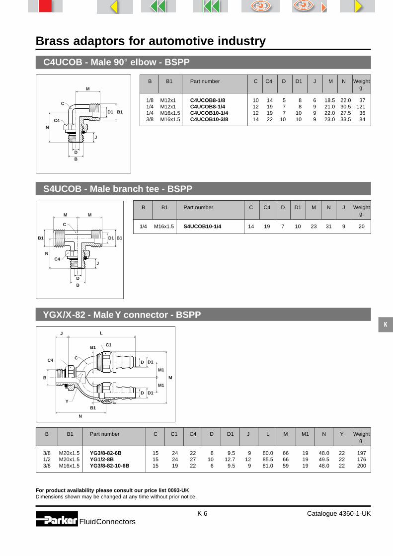
Brass adaptors for automotive industry
K 6 Catalogue 4360-1-UKFluidConnectors
K
For product availability please consult our price list 0093-UKDimensions shown may be changed at any time without prior notice.
C4UCOB - Male 90° elbow - BSPP
B B1 Part number C C4 D D1 J M N Weightg.
1/8 M12x1 C4UCOB8-1/8 10 14 5 8 6 18.5 22.0 371/4 M12x1 C4UCOB8-1/4 12 19 7 8 9 21.0 30.5 1211/4 M16x1.5 C4UCOB10-1/4 12 19 7 10 9 22.0 27.5 363/8 M16x1.5 C4UCOB10-3/8 14 22 10 10 9 23.0 33.5 84
B
M
D
B1D1
C
C4
J
N
YGX/X-82 - Male Y connector - BSPP
B B1 Part number C C1 C4 D D1 J L M M1 N Y Weightg.
3/8 M20x1.5 YG3/8-82-6B 15 24 22 8 9.5 9 80.0 66 19 48.0 22 1971/2 M20x1.5 YG1/2-8B 15 24 27 10 12.7 12 85.5 66 19 49.5 22 1763/8 M16x1.5 YG3/8-82-10-6B 15 19 22 6 9.5 9 81.0 59 19 48.0 22 200
B
B1
B1
N
J L
D1D
D1
M1
M1
M
D
�
C1
C C4
Y
S4UCOB - Male branch tee - BSPP
B B1 Part number C C4 D D1 M N J Weightg.
1/4 M16x1.5 S4UCOB10-1/4 14 19 7 10 23 31 9 20
B
MM
D
B1B1 D1
C
C4J
N

Brass adaptors for automotive industry
K 7 Catalogue 4360-1-UKFluidConnectors
K
For product availability please consult our price list 0093-UKDimensions shown may be changed at any time without prior notice.
YGX/XCO - Male Y connector - BSPP
B D
J
L
C
C4
B1D1
B1
M
M
D1
B B1 Part number C C4 D D1 J L M Weightg.
3/8 M16x1.5 YG3/8CO10COMP 22 22 11 10 9 57.0 19 683/8 M20x1.5 YG3/8CO14COMP 22 22 11 14 9 57.0 19 551/2 M20x1.5 YG1/2CO14COMP 22 27 14 14 12 61.5 19 62
B B1 Part number C C4 D J J1 L Weightg.
1/8 1/8 1/8F4UF4UB 14 14 4.5 6 6 12.5 301/4 1/4 1/4F4UF4UB 19 19 6.5 9 9 15.5 453/8 3/8 3/8F4UFU4B 22 22 10.0 9 9 17.5 621/2 1/2 1/2F4UF4UB 27 27 12.5 12 12 20.5 853/4 3/4 3/4F4UF4UB 32 32 18.0 12 12 22.5 95
F4UF4UB - Male equal pipe nipple - BSPP
B1B
C C4
L
J J1
D
F4UG4B - Male-female enlarging adaptor - BSPP
B B1 Part number C D J L Weightg.
1/8 1/8 1/8F4UG4B-20 4.5 14 6 20 311/4 1/4 1/4F4UG4B-20 6.5 19 9 20 521/4 1/4 1/4F4UG4B-30 6.5 19 9 30 761/4 1/4 1/4F4UG4B-50 6.5 19 9 50 1233/8 3/8 3/8F4UG4B-20 10.0 22 9 20 55
3/8 3/8 3/8F4UG4B-30 10.0 22 9 30 803/8 3/8 3/8F4UG4B-50 10.0 22 9 50 142
B D B1
C
J
L

Brass adaptors for automotive industry
K 8 Catalogue 4360-1-UKFluidConnectors
K
For product availability please consult our price list 0093-UKDimensions shown may be changed at any time without prior notice.
G2 G1
AW
E- Straight adaptor - metric 60° cone - BSPT
Thread
DN Part number G1 G2 A W Weightmetric BSPT mm mm g.
6 EG6-1/8B M12x1 1/8 23 14 206 EG6-1/4B M12x1 1/4 28 14 276 EG12x15-1/8B M12x1.5 1/8 23 14 206 EG12x15-1/4B M12x1.5 1/4 28 14 278 EG8-1/4B M14x1.5 1/4 28 17 36
8 EG8-3/8B M14x1.5 3/8 28 19 9410 EG10-1/4B M16x1.5 1/4 28 19 3010 EG10-1/2B M16x1.5 1/2 32 24 7310 EG10-3/8B M16x1.5 3/8 28 19 3512 EG15-1/2B M22x1.5 1/2 34 24 40
12 EG15-3/8B M22x1.5 3/8 34 24 7916 EG18-3/4B M26x1.5 3/4 38 27 247
EV - 45° elbow adaptor - metric 60° cone - BSPT
Thread
DN Part number G1 G2 B Weightmetric BSPT mm g.
6 EV6-1/8B M12x1 1/8 20 436 EV6-1/4B M12x1 1/4 20 438 EV8-1/4B M14x1.5 1/4 27 638 EV8-3/8B M14x1.5 3/8 27 97
10 EV10-1/4B M16x1.5 1/4 27 129
10 EV10-3/8B M16x1.5 3/8 27 19712 EV15-1/2B M22x1.5 1/2 30 11
G2
G1B
B
EW - 90° elbow adaptor - metric 60° cone - BSPT
Thread
DN Part number G1 G2 B Weightmetric BSPT mm g.
6 EW6-1/8B M12x1 1/8 20 296 EW6-1/4B M12x1 1/4 20 556 EW12x15-1/4B M12x1.5 1/4 20 888 EW8-1/4B M14x1.5 1/4 27 648 EW8-3/8B M14x1.5 3/8 27 151
10 EW10-1/4B M16x1.5 1/4 27 4510 EW10-3/8B M16x1.5 3/8 27 10012 EW15-1/2B M22x1.5 1/2 30 130
G2
G1
B
B

Brass adaptors for automotive industry
K 9 Catalogue 4360-1-UKFluidConnectors
K
For product availability please consult our price list 0093-UKDimensions shown may be changed at any time without prior notice.
Designed to be used in conjunction with Parker Push-Lok hose fittings H898 202 and H897 995for both welding robots and portable guns on water cooling and compressed air circuits. See thePush-Lok Hose and Fitting section (P).
M14-4V3 - Male nipple 45° elbow (Ford standard UW003-04180)
A B Part number C M N P Weightg.
1/4 M14x1.5 M14-4V3MX8BH17 14 18 17 12 45
M
BC
PN
A
37°
M14-4C3 - Male nipple 90° elbow (Ford standard UW003-04180)
A B Part number C M N P Weightg.
1/4 M14x1.5 M14-4C3MX8BH22 14 25 22 12 76
B
M C
NP
A
37° Designed to be used in conjunction with Parker Push-Lok hose fittings H898 202 and H897 995for both welding robots and portable guns on water cooling and compressed air circuits. See thePush-Lok Hose and Fitting section (P).
M14-4F3 - Male nipple straight fitting (Ford standard UW003-04180)
C
B37°
L
P
A
A B Part number C L P Weightg.
1/4 M14x1.5 M14-4F3MX8BL31 17 31 12 31
Designed to be used in conjunction with Parker Push-Lok hose fittings H898 202 andH897 995 for both welding robots and portable guns on water cooling and compressedair circuits. See the Push-Lok Hose and Fitting section (P).

Brass adaptors for automotive industry
K 10 Catalogue 4360-1-UKFluidConnectors
K
For product availability please consult our price list 0093-UKDimensions shown may be changed at any time without prior notice.
M14-4F63 - Male swivel nut straight fitting (Ford standard UW003-04180)
B
L
PO
C1 C
A
A B Part number C C1 L O P Weightg.
1/4 M14x1.5 M14-4F63MX8BL32 17 17 32 11 12 58
Designed to be used in conjunction with Parker Push-Lok hose fittings H898 202 and H897 995 for bothwelding robots and portable guns on water cooling and compressed air circuits. See the Push-Lok Hoseand Fitting section (P).
M14-4V63 - Male swivel nut 45° elbow (Ford standard UW003-04180)
A B Part number C C1 M N O P Weightg.
1/4 M14X1.5 M14-4V63MX8BH17 14 17 20 7 11 12 57C1
B
M
O
C
NP
A
M14-4C63 - Male swivel nut 90° elbow (Ford standard UW003-04180)
A B Part number C C1 M N O P Weightg.
1/4 M14x1.5 M14-4C63MX8BH22 14 17 24 22 11 12 62
B
ON
P
M
A
CC1
Designed to be used in conjunction with Parker Push-Lok hose fittings H898 202 and H897 995 for both weldingrobots and portable guns on water cooling and compressed air circuits. See the Push-Lok Hose and Fitting section (P).

Pneumatic adaptorsNickel plated brassadaptors forpneumatic applications
Catalogue 4360-2-UK

Pneumatic adaptors
L 2 Catalogue 4360-2-UKFluidConnectors
L
Pipeconnectorsand bulkheadunions
equal equal unequal unequal femalemetric BSPP metric BSPP BSPPGG88 - p. L 9 GG44 - p. L 10 GG84 - p. L 10 GG44 - p. L 10 WG44 - p. L 10
Reducers
female-male female-male female-male female-male extend. male-femaleBSPP-BSPT BSPP / metric BSPP BSPP BSPT-BSPPFG43 - p. L 7 FG48 - p. L 8 FG44 - p. L 8 FF41G4 - p. L 8 PTR34 - p. L 8
male-female male-female male-femaleBSPP / metric BSPP BSPPPTR48 - p. L 9 PTR44 - p. L 9 PTR44H - p. L 9
90° elbows
male female female-male femaleBSPT BSPP BSPP-BSPT BSPPCR33 - p. L 11 DD44 - p. L 11 CD43 - p. L 11 DD44BKTL - p. L 11
Index
Pipe nipples
equal unequal equal unequal equalBSPT BSPT BSPP BSPP metricFF33 - p. L 6 FF33 - p. L 6 FF44 - p. L 6 FF44 - p. L 6 FF88 - p. L 7
unequal male-malemetric / BSPP BSPTFF84 - p. L 7 FF633 - p. L 7

Pneumatic adaptors
L 3 Catalogue 4360-2-UKFluidConnectors
L
Y connectors
female female-female-maleBSPP BSPP-BSPP-BSPTYMMM444 -p. L 14 YMMS443 - p. L 14
Plugs andCaps
male male male male femaleBSPP metric BSPP BSPT BSPPP4UN - p. L 14 P80N - p. L 15 P40N - p. L 15 HHP3 - p. L 15 FN4 - p.L 15
Hosebarb fittings
female male maleBSPP BSPT BSPPFGH - p. L 16 F3H - p. L 16 F41H - p. L 17
Aluminiummanifoldsand washers
manifold manifold 1 manifold 2BSPP BSPP BSPP aluminium washer nylon washerMANIF - p. L 17 MANI1 - p. L 17 MANI2 - p. L 18 RRD - p. L 18 RRP - p. L 18
Index
Tees andCross
equal female equal male female-male-male female-female-male female-male-femaleBSPP BSPT BSPP-BSPT-BSPT BSPP-BSPP-BSPT BSPP-BSPT-BSPPMMO444 - p. L 12 RRS333 - p. L 12 MRS433 - p. L 12 MMS443 - p. L 12 MRO434 - p. L 13
male-male-female equal female fem-fem-male-fem. equal maleBSPT-BSPT-BSPP BSPP BSPP-BSPP-BSPT-BSPP BSPTRRO334 - p. L 13 KMMOO4 - p. L 13 KMRO4434- p. L 13 KRRS3- p. L 14

Pneumatic adaptors
L 4 Catalogue 4360-2-UKFluidConnectors
L
Parker pneumatic adaptors are produced from hot forgings to meet exactingtolerences.
The hot forging process increasesthe density of the material, refinesthe grain structure and improvesmaterial strength.
Principle
To simplify the installation of pneumatic systems, Parkersupplies a comprehensive range of adaptors with BSPT,BSPP and metric threads.The range includes pipe nipples, reducers, bulkheadunions, elbows, tees, crosses and plugs.The technical features of the pneumatic adaptors allowtheir use in several applications as well as with other com-patible products within the Parker range.
Technical features
* These adaptors have been designed for low pressure applications with the principal target to reduce space andweight. They are compatible with most of current threads used on this type of application. If a specific standard isrequired, please consult us.
Advantages
Brass forgings
Woking Workingpressure temperature
Material Threads*
Nickel plated BSPP from 0.01 from - 60°Cbrass BSPT
Metric to 15 bar to + 190°C

Pneumatic adaptors
L 5 Catalogue 4360-2-UKFluidConnectors
L
Brass nickel plated bodyBrass is a raw material providing :- robustness,- excellent shock resistance,- good temperature capability,- nickel plating gives improved
corrosion resistance and a brightappearance which does notdeteriorate.
Excellent featuresPneumatic adaptors have beendesigned to guarantee :- an efficient and economic solu-
tion for all applications,- compact dimensions where space
is at a premium,- a significant weight saving.
PackagingParker pneumatic adaptors arepackaged in biodegradable plasticbags preventing thread damage andensuring a quality adaptor.
Advantages

Pneumatic adaptors
L 6 Catalogue 4360-2-UKFluidConnectors
L
For product availability please consult our price list 0093-UK.Dimensions shown may be changed at any time without prior notice.
PP
A
C
L
A
FF33 - Equal pipe nipple - BSPT
FF33 - Unequal pipe nipple - BSPT
P1P2
A2
C
L
A1
FF44 - Equal pipe nipple - BSPP
B
C
L
JJ
B
FF44 - Unequal pipe nipple - BSPP
L
J1J2C
B1B2
These parts require two RRD or RRP washers to order separately.
B1 B2 Part number C J1 J2 L Weightg.
1/8 1/4 1/8x1/4FF44BL 17 6 8 19.0 15
1/8 3/8 1/8x3/8FF44BL 19 6 9 20.0 201/4 3/8 1/4x3/8FF44BL 19 8 9 22.0 211/4 1/2 1/4x1/2FF44BL 24 8 10 23.5 313/8 1/2 3/8x1/2FF44BL 24 9 10 24.5 341/2 3/4 1/2x3/4FF44BL 30 10 12 27.5 75
These parts require two RRD or RRP washers to order separately.
B Part number C J L Weightg.
1/8 1/8FF44BL 14 6 16.5 9
1/4 1/4FF44BL 17 8 21.0 173/8 3/8FF44BL 19 9 23.5 231/2 1/2FF44BL 24 10 25.5 34
A1 A2 Part number C L P1 P2 Weightg.
1/8 1/4 1/8x1/4FF33BL 14 23.5 7.5 11.0 141/8 3/8 1/8x3/8FF33BL 17 24.0 7.5 11.5 191/8 1/2 1/8x1/2FF33BL 22 27.0 7.5 14.0 321/4 3/8 1/4x3/8FF33BL 17 27.5 11.0 11.5 231/4 1/2 1/4x1/2FF33BL 22 30.5 11.0 14.0 35
3/8 1/2 3/8x1/2FF33BL 22 31.0 11.5 14.0 371/2 3/4 1/2x3/4FF33BL 27 37.5 14.0 16.5 673/4 1 3/4x1FF33BL 34 43.0 16.5 19.0 125
A Part number C L P Weightg.
1/8 1/8FF33BL 12 19.5 7.5 9
1/4 1/4FF33BL 14 27.0 11.0 173/8 3/8FF33BL 17 28.0 11.5 271/2 1/2FF33BL 22 33.5 14.0 413/4 3/4FF33BL 27 40.0 16.5 801 1FF33BL 34 45.5 19.0 145

Pneumatic adaptors
L 7 Catalogue 4360-2-UKFluidConnectors
L
A Part number C C1 L P Weightg.
1/8 1/8FF633BL 15 5 27.0 9.0 181/4 1/4FF633BL 19 6 33.5 11.5 363/8 3/8FF633BL 22 8 36.5 13.0 551/2 1/2FF633BL 27 12 45.0 15.5 903/4 3/4FF633BL 36 14 52.5 18.0 2611 1FF633BL 46 19 63.5 22.0 600
For product availability please consult our price list 0093-UK.Dimensions shown may be changed at any time without prior notice.
This part requires two RRD or RRP washers to order separately.
FF88 - Equal pipe nipple - Metric
B
C
L
JJ
B
FF84 - Unequal pipe nipple - Metric / BSPP
L
J1J2C
B1B2
This part requires two RRD or RRP washers to order separately.
FF633 - Swivel pipe nipple male-male - BSPT
PP
A
C
L
A
C1Fittings not nickel plated.
FG43 - Reducing connector female-male - BSPP-BSPT
P
L
C
AB
B1 B2 Part number C J1 J2 L Weightg.
M5 1/8 M5x1/8FF84BL 14 4 6 14.5 8
B Part number C J L Weightg.
M5 M5FF88BL 8 4 11.5 2
A B Part number C L P Weightg.
1/8 1/8 1/8FG43BL 14 20.0 7.5 111/8 3/8 3/8x1/8FG43BL 22 23.0 7.5 291/8 1/4 1/4x1/8FG43BL 17 22.0 7.5 181/4 1/4 1/4FG43BL 17 26.0 11.0 223/8 1/4 3/8x1/4FG43BL 22 27.0 11.0 34
1/2 1/4 1/2x1/4FG43BL 26 30.0 11.0 453/8 3/8 3/8FG43BL 22 27.5 11.0 371/2 3/8 1/2x3/8FG43BL 26 30.5 11.5 301/2 1/2 1/2FG43BL 26 33.0 14.0 503/4 1/2 3/4x1/2FG43BL 32 35.0 14.0 80

Pneumatic adaptors
L 8 Catalogue 4360-2-UKFluidConnectors
L
J
L
C
B2B1
These parts require one RRD or RRP washer to order separately.
J
L
C
B2B1
This part requires one RRD or RRP washer to order separately.
FG48 - Reducing connector female-male - BSPP / Metric
C P
L
AB
��
PTR34 - Pipe thread reducer male-female - BSPT-BSPP
J
B1B2
L
C
FF41G4 - Extended connector female-male - BSPP
These parts require one RRD or RRP washer to order separately.
B1 B2 Part number C J L Weightg.
1/8 M5 1/8xM5FG48BL 14 4 14.5 8
B1 B2 Part number C J L Weightg.
1/8 1/8 1/8FG44BL 14 6 17.0 11
3/8 1/8 3/8x1/8FG44BL 22 6 21.5 291/4 1/8 1/4x1/8FG44BL 17 6 20.5 181/4 1/4 1/4FG44BL 17 8 22.5 19
3/8 1/4 3/8x1/4FG44BL 22 8 23.5 313/8 3/8 3/8FG44BL 22 9 24.5 331/2 1/4 1/2x1/4FG44BL 26 8 26.5 421/2 3/8 1/2x3/8FG44BL 26 9 27.5 451/2 1/2 1/2FG44BL 26 10 28.5 46
B1 B2 Part number C J L Weightg.
1/8 1/8 1/8FF41G4BL22L 14 6 22 15
1/8 1/8 1/8FF41G4BL42L 14 6 42 271/4 1/4 1/4FF41G4BL35L 17 8 35 301/4 1/4 1/4FF41G4BL51L 17 8 51 44
FG44 - Reducing connector female-male - BSPP
A B Part number C L P Weightg.
1/4 1/8 1/4x1/8PTR34BL 14 16.0 11.0 11
3/8 1/8 3/8x1/8PTR34BL 17 16.5 11.5 121/2 1/8 1/2x1/8PTR34BL 22 19.5 14.0 463/8 1/4 3/8x1/4PTR34BL 17 16.5 11.5 141/2 1/4 1/2x1/4PTR34BL 22 19.5 14.0 37
1/2 3/8 1/2x3/8PTR34BL 22 19.5 14.0 253/4 3/8 3/4x3/8PTR34BL 27 23.5 16.5 473/4 1/2 3/4x1/2PTR34BL 27 23.5 16.5 481 1/2 1x1/2PTR34BL 34 26.5 19.0 1301 3/4 1x3/4PTR34BL 34 26.5 19.0 771.1/4 1/2 1.1/4x1/2PTR34BL 45 31.0 22.0 220

Pneumatic adaptors
L 9 Catalogue 4360-2-UKFluidConnectors
L
B1 B2 Part number C J L Weightg.
1/8 M5 1/8xM5PTR48BL 14 6 10.5 8
For product availability please consult our price list 0093-UK.Dimensions shown may be changed at any time without prior notice.
B1B2
CJ
L
PTR48 - Pipe thread reducer male-female - BSPP / Metric
This part requires one RRD or RRP washer to order separately.
B1B2
CJ
L
PTR44 - Pipe thread reducer male-female - BSPP
These parts require one RRD or RRP washer to order separately.
PTR44H - Pipe thread reducer male-female - BSPP
B1 B2
L
Fittings not nickel plated.
GG88 - Equal pipe connector - Metric
L
C
B
B1 B2 Part number C J L Weightg.
1/4 1/8 1/4x1/8PTR44BL 17 8 13.0 103/8 1/8 3/8x1/8PTR44BL 19 9 14.0 191/2 1/8 1/2x1/8PTR44BL 24 10 15.5 393/8 1/4 3/8x1/4PTR44BL 19 9 14.0 131/2 1/4 1/2x1/4PTR44BL 24 10 15.5 32
1/2 3/8 1/2x3/8PTR44BL 24 10 15.5 333/4 3/8 3/4x3/8PTR44BL 30 12 17.5 543/4 1/2 3/4x1/2PTR44BL 30 12 17.5 38
B1 B2 Part number L Weightg.
1/8 1/4 1/4x1/8PTR44HBL 8 31/4 3/8 3/8x1/4PTR44HBL 9 53/8 1/2 1/2x3/8PTR44HBL 10 71/2 3/4 3/4x1/2PTR44HBL 14 193/4 1 1x3/4PTR44HBL 20 41
B Part number C L Weightg.
M5 M5GG88BL 8 11 3

Pneumatic adaptors
L 10 Catalogue 4360-2-UKFluidConnectors
L
For product availability please consult our price list 0093-UK.Dimensions shown may be changed at any time without prior notice.
GG84 - Unequal pipe connector - Metric
L
B1B2
C
GG44 - Equal pipe connector - BSPP
L
C
B
WGG44 - Bulkhead female union - Metric or BSPP
CC1
B1 B
W
J T
GG44 - Unequal pipe connector - BSPP
L
B1B2
C
B1 B2 Part number C L Weightg.
M5 1/8 M5x1/8GG84BL 14 13 10
B Part number C L Weightg.
1/8 1/8GG44BL 14 15 151/4 1/4GG44BL 17 22 183/8 3/8GG44BL 22 24 341/2 1/2GG44BL 26 30 543/4 3/4GG44BL 32 32 78
B1 B2 Part number C L Weightg.
1/8 1/4 1/8x1/4GG44BL 17 19.0 161/8 3/8 1/8x3/8GG44BL 22 20.0 231/8 1/2 1/8x1/2GG44BL 24 20.0 151/4 3/8 1/4x3/8GG44BL 22 23.0 291/4 1/2 1/4x1/2GG44BL 24 25.0 30
3/8 1/2 3/8x1/2GG4BL 24 27.5 311/2 1 1/2x1GG44BL 40 39.0 1453/4 1/2 3/4x1/2GG44BL 30 30.0 333/4 1 3/4x1GG44BL 40 41.0 146
B Part number B1 C C1 J T W WeightMax. g.
M5 M5WGG44BL M10x1.5 14 14 10.5 3.5 7 121/8 1/8WGG44BL M16x1.5 19 22 14.0 4.0 10 301/4 1/4WGG44BL M20x1.5 24 27 21.0 4.0 16 553/8 3/8WGG44BL M26x1.5 30 32 21.0 5.0 15 931/2 1/2WGG44BL M28x1.5 32 36 27.0 6.0 21 112
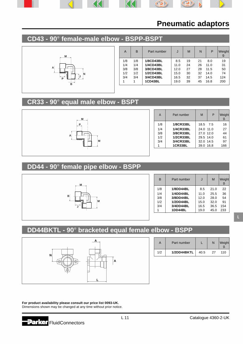
Pneumatic adaptors
L 11 Catalogue 4360-2-UKFluidConnectors
L
For product availability please consult our price list 0093-UK.Dimensions shown may be changed at any time without prior notice.
CD43 - 90° female-male elbow - BSPP-BSPT
A
B
N
P
M
J
CR33 - 90° equal male elbow - BSPT
A
M
P
M
DD44 - 90° female pipe elbow - BSPP
B
M
J
M
DD44BKTL - 90° bracketed equal female elbow - BSPP
���������������������������������������������������������������������������������������������������������������������
A
A
L
N
A Part number M P Weightg.
1/8 1/8CR33BL 18.5 7.5 16
1/4 1/4CR33BL 24.0 11.0 273/8 3/8CR33BL 27.0 12.0 441/2 1/2CR33BL 29.5 14.0 613/4 3/4CR33BL 32.0 14.5 971 1CR33BL 39.0 16.8 166
B Part number J M Weightg.
1/8 1/8DD44BL 8.5 21.0 22
1/4 1/4DD44BL 11.0 25.5 363/8 3/8DD44BL 12.0 28.0 541/2 1/2DD44BL 15.0 32.0 913/4 3/4DD44BL 16.5 36.5 1541 1DD44BL 19.0 45.0 233
A Part number L N Weightg.
1/2 1/2DD44BKTL 40.5 27 110
A B Part number J M N P Weightg.
1/8 1/8 1/8CD43BL 8.5 19 21 8.0 191/4 1/4 1/4CD43BL 11.0 24 26 11.0 313/8 3/8 3/8CD43BL 12.0 27 28 11.5 501/2 1/2 1/2CD43BL 15.0 30 32 14.0 743/4 3/4 3/4CD43BL 16.5 32 37 14.5 1241 1 1CD43BL 19.0 39 45 16.8 200

Pneumatic adaptors
L 12 Catalogue 4360-2-UKFluidConnectors
L
For product availability please consult our price list 0093-UK.Dimensions shown may be changed at any time without prior notice.
MMO444 - Female pipe tee - BSPP
B
JN
L
A
NP
L
MRS433 - Run tee female-male-male - BSPT-BSPP-BSPT
A
J
B
NP
L
MMS443 - Branch tee female-female-male - BSPP-BSPP-BSPT
A
J
B
NP
L
B Part number J L N Weightg.
1/8 1/8MMO444BL 8.5 39 19.5 301/4 1/4MMO444BL 11.0 49 24.5 503/8 3/8MMO444BL 12.0 54 27.0 721/2 1/2MMO444BL 15.0 64 32.0 1323/4 3/4MMO444BL 16.5 73 36.5 2201 1MMO444BL 19.0 90 45.0 325
A Part number L N P Weightg.
1/8 1/8RRS333BL 35.0 17.5 8.0 201/4 1/4RRS333BL 46.0 23.0 11.0 363/8 3/8RRS333BL 51.5 25.5 11.5 551/2 1/2RRS333BL 59.0 29.5 14.0 853/4 3/4RRS333BL 64.0 32.0 14.5 1271 1RRS333BL 78.0 39.0 16.8 208
RRS333 - Male pipe tee - BSPT
A B Part number J L N P Weightg.
1/8 1/8 1/8MRS433BL 8.5 37.0 17.5 8.0 231/4 1/4 1/4MRS433BL 11.0 47.5 23.0 11.0 403/8 3/8 3/8MRS433BL 12.0 52.5 25.5 11.5 611/2 1/2 1/2MRS433BL 15.0 61.5 29.5 14.0 983/4 3/4 3/4MRS433BL 16.5 68.5 29.5 14.5 1571 1 1MRS433BL 19.0 84.0 29.5 16.8 244
A B Part number J L N P Weightg.
1/8 1/8 1/8MMS443BL 8.5 39 18 8.0 261/4 1/4 1/4MMS443BL 11.0 49 23 11.0 443/8 3/8 3/8MMS443BL 12.0 54 26 11.5 651/2 1/2 1/2MMS443BL 15.0 64 29 14.0 1183/4 3/4 3/4MMS443BL 16.5 73 32 14.5 1901 1 1MMS443BL 19.0 90 39 16.8 280

Pneumatic adaptors
L 13 Catalogue 4360-2-UKFluidConnectors
L
For product availability please consult our price list 0093-UK.Dimensions shown may be changed at any time without prior notice.
MRO434 - Run tee female-male-female - BSPP-BSPT-BSPP
B
P
A
JN
L
RRO334 - Branch tee male-male-female - BSPT-BSPT-BSPP
N
B
A
P
J
L
KMMOO4 - Female pipe cross - BSPP
J
B L
L
KMRO4434 - Cross fem.-fem.-male-fem. - BSPP-BSPP-BSPT-BSPP
J
B L
L
P
A
A B Part number J L N P Weightg.
1/8 1/8 1/8MRO434BL 8.5 37 20 8.0 251/4 1/4 1/4MRO434BL 11.0 48 25 11.0 453/8 3/8 3/8MRO434BL 12.0 53 27 11.5 651/2 1/2 1/2MRO434BL 15.0 62 32 14.0 1163/4 3/4 3/4MRO434BL 16.5 69 37 14.5 1911 1 1MRO434BL 19.0 84 45 16.8 285
A B Part number J L N P Weightg.
1/8 1/8 1/8RRO334BL 8.5 35 19.5 8.0 231/4 1/4 1/4RRO334BL 11.0 46 24.5 11.0 403/8 3/8 3/8RRO334BL 12.0 51 27.0 11.5 591/2 1/2 1/2RRO334BL 15.0 59 32.0 14.0 983/4 3/4 3/4RRO334BL 16.5 64 36.5 14.5 1591 1 1RRO334BL 19.0 78 45.0 16.8 245
B Part number J L Weightg.
1/8 1/8KMMOO4BL 8.5 39 361/4 1/4KMMOO4BL 11.0 50 603/8 3/8KMMOO4BL 12.0 56 961/2 1/2KMMOO4BL 15.0 64 160
A B Part number J L P Weightg.
1/8 1/8 1/8KMRO4434BL 8.5 39 8.5 331/4 1/4 1/4KMRO4434BL 11.0 50 11.0 573/8 3/8 3/8KMRO4434BL 12.0 56 11.5 891/2 1/2 1/2KMRO4434BL 15.0 64 14.0 144

Pneumatic adaptors
L 14 Catalogue 4360-2-UKFluidConnectors
L
For product availability please consult our price list 0093-UK.Dimensions shown may be changed at any time without prior notice.
KRRS3 - Male pipe cross - BSPT
L
L
P
A
YMMM444 - Y connector female - BSPP
BJ J
B 90°
C
YMMS443 - Y connector female-female-male - BSPP-BSPP-BSPT
A
P
J B
90°
C
P4UN - Hollow hex head plug - O-Ring sealing
�L2C
L1
J
B
A Part number P L Weightg.
1/8 1/8KRRS3BL 8.5 35 241/4 1/4KRSS3BL 11.0 47 46
3/8 3/8KRSS3BL 11.5 52 701/2 1/2KRSS3BL 14.0 58 100
B Part number C J Weightg.
1/8 1/8YMMM444BL 14 8.0 321/4 1/4YMMM444BL 17 11.0 423/8 3/8YMMM444BL 22 11.5 921/2 1/2YMMM444BL 26 14.0 150
A B Part number C J P Weightg.
1/8 1/8 1/8YMMS443BL 14 8.0 9.0 311/4 1/4 1/4YMMS443BL 17 11.0 11.0 413/8 3/8 3/8YMMS443BL 22 11.5 12.5 871/2 1/2 1/2YMMS443BL 26 14.0 16.5 138
B Part number C J L1 L2 Weightg.
1/8 1/8P4UNBL 5 6 8.5 14 61/4 1/4P4UNBL 6 8 11.0 17 103/8 3/8P4UNBL 8 9 12.5 20 181/2 1/2P4UNBL 10 10 13.5 25 30

Pneumatic adaptors
L 15 Catalogue 4360-2-UKFluidConnectors
L
For product availability please consult our price list 0093-UK.Dimensions shown may be changed at any time without prior notice.
P80N - Hex head plug - Metric
C
L
J
B
This part requires one RRD or RRP washer to order separately.
P40N - Hex head plug - BSPP
C
L
J
B
These parts require one RRD or RRP washer to order separately.
HHP3 - Hollow hex head plug - BSPT
A
P
C5
L
FN4 - Hex head cap - BSPP
B
L
J
C
B Part number C J L Weightg.
M5 M5P80NBL 8 4.5 8 2
B Part number C J L Weightg.
1/8 1/8P4ONBL 14 6.5 10.0 61/4 1/4P4ONBL 17 9.0 13.0 123/8 3/8P4ONBL 19 9.5 13.5 151/2 1/2P4ONBL 24 10.0 14.5 273/4 3/4P4ONBL 30 11.0 16.0 481 1P4ONBL 40 12.0 17.0 88
A Part number C5 L P Weightg.
1/8 1/8HHP3BL 5 8 5.0 21/4 1/4HHP3BL 6 10 7.0 73/8 3/8HHP3BL 8 11 7.5 131/2 1/2HHP3BL 10 13 8.0 25
B Part number C J L Weightg.
1/8 1/8FN4BL 12 7.5 11 51/4 1/4FN4BL 14 11.0 19 153/8 3/8FN4BL 17 11.5 20 251/2 1/2FN4BL 19 14.0 22 40

Pneumatic adaptors
L 16 Catalogue 4360-2-UKFluidConnectors
L
For product availability please consult our price list 0093-UK.Dimensions shown may be changed at any time without prior notice.
FGH - Female hose adaptor - BSPP
1B
C
J
L
L1
F3H - Male hose adaptor - BSPT
P
L
C
1A
L1
1 B Part number C J L L1 Weightg.
6 1/8 FGHBL6-1/8BL 14 8.5 30.0 19.5 117 1/8 FGHBL7-1/8BL 14 8.5 30.0 19.5 127 1/4 FGHBL7-1/4BL 17 11.0 32.5 19.5 198 1/4 FGHBL8-1/4BL 17 11.0 32.5 19.5 199 1/4 FGHBL9-1/4BL 17 11.0 32.5 19.5 20
9 3/8 FGHBL9-3/8BL 20 11.5 33.5 19.5 2510 3/8 FGHBL10-3/8BL 20 11.5 33.5 19.5 2512 3/8 FGHBL12-3/8BL 20 11.5 33.5 19.5 2712 1/2 FGHBL12-1/2BL 24 14.5 37.5 19.5 40
1 A Part number C L L1 P Weightg.
6 1/8 F3HBL6-1/8BL 12 32.0 19.5 7.5 96 1/4 F3HBL6-1/4BL 14 35.5 19.5 11.0 147 1/8 F3HBL7-1/8BL 12 32.0 19.5 7.5 97 1/4 F3HBL7-1/4BL 14 35.5 19.5 11.0 148 1/8 F3HBL8-1/8BL 12 32.0 19.5 7.5 10
8 1/4 F3HBL8-1/4BL 14 35.5 19.5 11.0 159 1/8 F3HBL9-1/8BL 12 32.0 19.5 7.5 129 1/4 F3HBL9-1/4BL 14 35.5 19.5 11.0 159 3/8 F3HBL9-3/8BL 17 36.0 19.5 11.5 219 1/2 F3HBL9-1/2BL 22 39.0 19.5 14.0 32
10 1/8 F3HBL10-1/8BL 12 32.0 19.5 7.5 1010 1/4 F3HBL10-1/4BL 14 35.5 19.5 11.0 1510 3/8 F3HBL10-3/8BL 17 36.0 19.5 11.5 2210 1/2 F3HBL10-1/2BL 22 39.0 19.5 14.0 3312 1/4 F3HBL12-1/4BL 14 35.5 19.5 11.0 19
12 3/8 F3HBL12-3/8BL 17 36.0 19.5 11.5 2112 1/2 F3HBL12-1/2BL 22 39.0 19.5 14.0 3314 3/8 F3HBL14-3/8BL 17 36.0 19.5 11.5 2314 1/2 F3HBL14-1/2BL 22 39.0 19.5 14.0 3616 3/8 F3HBL16-3/8BL 17 36.0 19.5 11.5 26
16 1/2 F3HBL16-1/2BL 22 39.0 19.5 14.0 3816 3/4 F3HBL16-3/4BL 27 43.5 19.5 16.5 6217 3/8 F3HBL17-3/8BL 18 36.0 19.5 11.5 3017 1/2 F3HBL17-1/2BL 22 39.0 19.5 14.0 4318 3/8 F3HBL18-3/8BL 19 36.0 19.5 11.5 31
18 1/2 F3HBL18-1/2BL 22 39.0 19.5 14.0 4318 3/4 F3HBL18-3/4BL 27 43.5 19.5 16.5 6220 3/8 F3HBL20-3/8BL 21 36.0 19.5 11.5 3820 1/2 F3HBL20-1/2BL 22 39.0 19.5 14.0 46

Pneumatic adaptors
L 17 Catalogue 4360-2-UKFluidConnectors
L
For product availability please consult our price list 0093-UK.Dimensions shown may be changed at any time without prior notice.
MANIF - Aluminium manifold - BSPP
L
L Z
B
T
T
Q
MANI1 - Aluminium manifold - BSPP
L
n°
L2
L2B2
B1
L1
L1
L1
Z Y
F41H - Male hose adaptor - Metric or BSPP
L
CJ
1B
L1��
1 B Part number C J L L1 Weightg.
4.5 M5 F41HBL4.5-M5BL 8 4 23.0 15 37 1/8 F41HBL7-1/8BL 14 6 30.0 20 117 1/4 F41HBL7-1/4BL 17 8 33.0 20 198 1/8 F41HBL8-1/8BL 14 6 30.0 20 129 1/8 F41HBL9-1/8BL 14 6 30.0 20 12
9 1/4 F41HBL9-1/4BL 17 8 33.0 20 199 3/8 F41HBL9-3/8BL 19 9 34.0 20 24
12 1/4 F41HBL12-1/4BL 17 8 33.0 20 2112 3/8 F41HBL12-3/8BL 19 9 34.0 20 2512 1/2 F41HBL12-1/2BL 24 10 37.5 22 42
17 3/8 F41HBL17-3/8BL 19 9 38.0 24 3117 1/2 F41HBL17-1/2BL 24 10 39.5 24 46
B Part number L Q T Z Weightg.
1/8 MANIF1/8KMO4DL 25 4.5 4.3 16 161/4 MANIF1/4KMO4DL 40 5.5 6.5 20 633/8 MANIF3/8KMO4DL 50 5.5 7.5 25 1261/2 MANIF1/2KMO4DL 50 5.5 7.5 30 136
B1 B2 N° Part number L L1 L2 Y Z Weightg.
1/8 M5 7 MANI1x1/8xM5x7 95 10.5 16 20 15 681/4 1/8 2 MANI1x1/4x1/8x2 60 30.0 15 30 20 781/4 1/8 3 MANI1x1/4x1/8x3 90 30.0 15 30 20 1631/4 1/8 4 MANI1x1/4x1/8x4 120 30.0 15 30 20 2141/4 1/8 5 MANI1x1/4x1/8x5 150 30.0 15 30 20 265
1/4 1/8 6 MANI1x1/4x1/8x6 180 30.0 15 30 20 3163/8 1/4 2 MANI1x3/8x1/4x2 72 36.0 18 30 20 803/8 1/4 3 MANI1x3/8x1/4x3 108 36.0 18 30 20 1933/8 1/4 4 MANI1x3/8x1/4x4 144 36.0 18 30 20 2553/8 1/4 5 MANI1x3/8x1/4x5 180 36.0 18 30 20 1803/8 1/4 6 MANI1x3/8x1/4x6 216 36.0 18 30 20 377

Pneumatic adaptors
L 18 Catalogue 4360-2-UKFluidConnectors
L
For product availability please consult our price list 0093-UK.Dimensions shown may be changed at any time without prior notice.
MANI2 - Aluminium manifold - BSPP
L
n°
L2
L2B2
B1
L1
L1
L1
Z Y
L1
L
L2
RRD - Aluminium washer
RRP - Nylon washer
L1
L
L2
B1 B2 N° Part number L L1 L2 Y Z Weightg.
1/4 1/8 2 MANI2x1/4x1/8x2 60 30 15 30 20 761/4 1/8 3 MANI2x1/4x1/8x3 90 30 15 30 20 1171/4 1/8 4 MANI2x1/4x1/8x4 120 30 15 30 20 1561/4 1/8 5 MANI2x1/4x1/8x5 150 36 18 30 20 2043/8 1/4 2 MANI2x3/8x1/4x2 72 36 18 40 20 177
3/8 1/4 3 MANI2x3/8x1/4x3 108 36 18 40 20 2603/8 1/4 4 MANI2x3/8x1/4x4 144 36 18 40 20 3423/8 1/4 5 MANI2x3/8x1/4x5 180 36 18 40 20 424
Size Part number L L1 L2 Weightg.
M5 M5RRP 8 5.1 1.3 0.11/8 1/8RRP 14 9.8 1.8 0.11/4 1/4RRP 18 13.2 1.8 0.13/8 3/8RRP 21 16.7 1.8 0.21/2 1/2RRP 26 21.1 1.8 0.3
3/4 3/4RRP 33 28.0 2.5 0.71 1RRP 41 34.0 2.5 1.0
Size Part number L L1 L2 Weightg.
M5 M5RRD 8 5.2 1.0 0.11/8 1/8RRD 14 10.0 1.5 0.11/4 1/4RRD 18 13.5 1.5 0.13/8 3/8RRD 21 16.5 1.5 0.11/2 1/2RRD 26 21.1 1.5 0.2

Ball valves
Catalogue 3529-UK

Ball valves
M 2 Catalogue 3529-UKFluidConnectors
M
Acetone E E E U U E U E E EAcetylene G E E G P E E E EAir E E E E E E E E E EAlcohol, ethyl G G G E G E E E E GAlcohol, methyl E G E G E E P E E GAnimal oil G G G E G G E GAsphalt emulsion E G E U P U E E E GAsphalt liquid E G E P P U E E E GBeer G U E G G G E E E UBenzene G G G U U U G E EButane E G E G G U E E E PCalcium chloride G P G E E G E E E UCarbonated water G G E E E E E E E ECaustic soda G E P G G ECoffee E E E E E E GCutting oils E G E E G E E EDiesel oil fuels E E E E P U E E GEthanol E U U U E E U GEthyl alcohol G G G E E E EFerrous sulphate G U G E E E E E E UGas, natural G G E E E U E E EGasoline, unleaded E E E P U E E E EGlucose E G E E E E E E EGlycerine G P E P U E G E P EKerosene E G E E P U E E E GMethane E G E E G E E EMethanol G E G G U G E GMethyl alcohol G G G E G P E EMilk & milk products G U E E E E E E E GMineral oils G G E E G U E E E GNaphtha G G G G P U E E E GNatural gas, sour G G E E E U E ENitric acid 100% U U E U U U G E U UNitric acid 30% U U E P P G E E U UNitrogen E E E E E G E E E GPaints & solvents E E E U U U G E GPaper pulp G E G G G G EParaffin E G E E P U E E EPetrolatum (Petroleum Jelly) G P G E G E E EPropane gas E G G E G U E E ESea water P U G E E E E E ESodium chloride G P G E E G E E E ESteam (100°C) E E E U U G P E USulphur U P G U P G G E ETrichlorethylene G G G U U U G E E UWater, distilled E U E P G G E E E EWater, fresh E P E P G G E E E E
Media Guide
The table below lists general recommendations for the selection of valve materials. For specific cases, and forthose not included in the Media Guide, it is advisable to check with your Parker representative.There are many specific environmental factors which may affect corrosion rate, such as temperature, solution,concentration and presence of impurities. Therefore, we recommend that the information be used only as aguide to material selection. If any questions exist regarding the expected performance of a material in a givenapplication, actual tests should be performed to determine the suitability of the materials in question.
BrassCarbon
steel
Stainlesssteel(316)
Buna N(Nitrile)
Neoprene EPRFluoro-carbon
PTFE Acetal Nylon(Polyamide)
E = Excellent G = Good P = Poor U = Unsatisfactory
Fluid

Ball valves
FluidConnectors
M
M 3 Catalogue 3529-UK
IndexBVGC series -BSPP shortthreads - Generalpurpose
female / female valvewith compact handleBSPPBVGTC - p. M 5
female / female valvewith lever handleBSPPBVGC - p. M 5
BVGL series -BSPP longthreads - Generalpurpose
female / female valvewith compact handleBSPPBVGTL - p. M 7
female / female valvewith lever handleBSPPBVGL - p. M 7
MBVG series -BSPP shortthreads - Compact
female / female valveBSPPMBVG - p. M 9
BVG4PLOCKseries -BSPP-longthreads -lockable ventedvalve
female / female valveBSPPBVG4PLOCK - p. M 11
200PSI

Ball valves
M 4 Catalogue 3529-UKFluidConnectors
M
BVGC series
Technical features
For operator safety the BVGC series valves are fitted with anti-extrusion stems to prevent blow out and all valvesare 100% pressure tested to ensure zero leakage.
* For other thread configurations please consult your Parker sales engineer.
Operating pressures and temperatures
N.B.
This chart gives general information. Only testing under operating conditions will finally determine which valve should be selected.
1/4" - 3/8"1/2"3/4"1"11/4"11/2"2"
0-200
10
20
30
50 100 170150
PrincipleParker BVGC series economy ballvalves are designed for use in awide variety of fluid applications.Available with BSPP female/female*short threads to ISO-228, they arefull flow valves giving minimumpressure drop.The BVGC series has a doublePTFE seal on the ball enabling thevalve to be used with flow in eitherdirection.All seals are treated with a siliconefree lubricant enabling the valvesto be used in water-based paintspray applications.-BVGC seriesvalves have an adjustable PTFEpacking gland for easymaintenance and longer service
Body Leverhandle
Compacthandle
Antiextrusion
stem
Stempackinggland
Ball Antifriction
ring
Forcingnut
Threads Pressure
Carbon steelwith yellow
PVC coating
Aluminiumwith yellow
epoxycoating
PTFE Brasschromeplated
PTFE Nickelplatedbrass
1/4" - 2"BSPP toISO228/DIN259
Seechartbelow
Nickelplated brass
toDIN17660 andUNI5705 spec.
Nickelplatedbrass
Pre
ssu
re (
bar
)
Temperature (°C)

Ball valves
FluidConnectors
M
M 5 Catalogue 3529-UK
For product availability please consult our price list 0093-UK.Dimensions shown may be changed at any time without prior notice.
Advantages
Adjustable packingThe PTFE packing gland andadjustable washer are designed togive longer service life and loweroperating torques.See instruction 3529-F/GB/D con-tained in each box.
Anti extrusion stemThe BVGC series ball valves arefitted with an anti-extrusion stem toprevent blow out in the case ofpressure peaks.
Compact handleFor applications where space is at apremium, the BVGC series valve isavailable with a compact handle forsizes up to 1".
BVGC - BSPP female / female valve with lever handle
This series is also available with red handle.-To order, add R to the part number,eg. BVG4-1/4CR.
CO
L1
H
L
B
I
CO
L1
H
L
B
I
DN B Part number C H L L1 O I Weightmm g.
8 1/4 BVG4-1/4C 20 39.5 39 82 25.0 9 13010 3/8 BVG4-3/8C 20 39.5 39 82 25.0 9 12015 1/2 BVG4-1/2C 25 44.0 50 100 32.5 11 20020 3/4 BVG4-3/4C 31 50.0 54 120 39.0 12 31225 1 BVG4-1C 38 54.0 67 120 47.5 14 440
32 1.1/4 BVG4-1.1/4C 48 76.5 77 158 59.0 15 73040 1.1/2 BVG4-1.1/2C 54 82.5 90 158 71.5 17 97250 2 BVG4-2C 66 89.5 106 158 86.0 19 1500
DN B Part number C H L L1 O I Weightmm g.
8 1/4 BVGT4-1/4C 20 40 39 50 25.0 9 13010 3/8 BVGT4-3/8C 20 40 39 50 25.0 9 12015 1/2 BVGT4-1/2C 25 44 50 50 32.5 11 18020 3/4 BVGT4-3/4C 31 49 54 60 39.0 12 26525 1 BVGT4-1C 38 53 67 60 47.5 14 390
BVGTC - BSPP female / female valve with compact handle

Ball valves
M 6 Catalogue 3529-UKFluidConnectors
M
BVGL series
Technical features
BVGL series valves are fitted with an anti-extrusion stem with two Fluorocarbon seals for maximum safety andperformance. After assembly all valves are 100% pressure tested to ensure zero leakage.
* For other thread configurations please consult us.
Operating pressures and temperatures
N.B.
This chart gives general information. Only testing under operating conditions will finally determine which valve should be selected.
Body Leverhandle
Compacthandle
Antiextrusion
stem
Stemseal
Ball Antifriction
ring
Forcingnut
Valvedimensions
Pressure
Brass nickelplated to
DIN17660 andUNI5705 spec.
Carbon steelwith yellow
PVC coating
Aluminiumwith yellow
epoxycoating
Brassnickelplated
TwoFluorocarbon
O-rings
Brasschromeplated
PTFE Brassnickelplated
Inaccordance
withDIN3357
Seechartbelow
PrincipleParker BVGL series valves aredesigned for use in fluid and gasapplications and are DVGWapproved.-The valve dimensions arein accordance with DIN3357 forinterchangeability and are availablewith BSPP female/female* longthreads to DIN 2999/ ISO 228.These full flow ball valves have achrome plated ball with a doublePTFE seal system enabling thevalve to be used with flow in eitherdirection.All seals are treated with a siliconefree lubricant enabling the valves tobe used in water based paint sprayapplications.
1/4" - 3/8"1/2"3/4"1"11/4"11/2"2"
0-200
10
20
30
50 100 170150
Pre
ssu
re (
bar
)
Temperature (°C)

Ball valves
FluidConnectors
M
M 7 Catalogue 3529-UK
Advantages
DIN 2999 / ISO 228 female threadsBVGL series valves are manufac-tured with long female threads inaccordance to DIN 2999 / ISO 228.This enables the valves to be usedwith Prestolok, Metrulok and brassadaptors but also Parker's range ofs tee l hydrau l i c f i t t i ngs andEO-fittings form “A” or “C” to DIN3852.
Anti extrusion stemThe BVGL series ball valves arefitted with an anti extrusion stem toprevent blow out in the case ofpressure peaks. The stem is sealedwith two Fluorocarbon O-rings formaximum safety and performance.
Full flowAll BVGL series valves are full-flow.This limits the turbulence created bythe passage of fluid across thevalve, minimizing pressure drop.
BVGL- BSPP female / female valve with lever handle
This series is also available with red handle.-To order, add R to the part number,eg. BVG4-1/4LR.
BVGTL - BSPP female / female valve with compact handle
CO
L1
H
L
B
I
CO
L1
H
L
B
I
DN B Part number C H L L1 O I Weightmm g.
8 1/4 BVG4-1/4L 20 38 50 82 25.0 12.0 15010 3/8 BVG4-3/8L 20 38 60 82 25.0 12.0 15015 1/2 BVG4-1/2L 25 43 75 100 32.5 15.5 25520 3/4 BVG4-3/4L 32 50 80 120 39.0 17.0 39025 1 BVG4-1L 41 54 90 120 47.5 21.0 590
32 1.1/4 BVG4-1.1/4L 50 73 110 158 59.0 23.0 98040 1.1/2 BVG4-1.1/2L 55 79 120 158 71.5 23.0 120550 2 BVG4-2L 70 86 140 158 86.0 26.5 1960
DN B Part number C H L L1 O I Weightmm g.
8 1/4 BVGT4-1/4L 20 39 50 50 25.0 12.0 15010 3/8 BVGT4-3/8L 20 39 60 50 25.0 12.0 15015 1/2 BVGT4-1/2L 25 43 75 50 32.5 15.5 23020 3/4 BVGT4-3/4L 32 47 80 60 39.0 17.0 35025 1 BVGT4-1L 41 51 90 60 47.5 21.0 550

Ball valves
M 8 Catalogue 3529-UKFluidConnectors
M
MBVG series
PrincipleThe MBVG series ball valves withtheir compact design offer the solu-tion to applications where spaceis an important factor. The body isof a particularly robust design. Theintegrity of the sealing on the ball isobtained by the use of PTFE seats.The valves are available with BSPPfemale threads ISO-228/1 (DIN 299)in : 1/4" 3/8" and 1/2" .
Technical features
Operating pressures and temperatures
N.B.This chart gives general information. Only testing under operating conditions will finally determine which valve should be selected.
-20 50
1/2"
1/8" - 1/4" - 3/8"
9000
5
10
15
Handle Anti-extrusionBody retention Handle Stem Stem seal Ball guide Nut Seat seals Pressure
screw pin
Brass Brass Polyamide Brass Fluorocarbon Brass Stainless Brass PTFE See chartchromium chromium chromium steel below
plated plated plated
Pre
ssu
re (
bar
)
Temperature (°C)

Ball valves
FluidConnectors
M
M 9 Catalogue 3529-UK
Advantages
Design of the bodyThe valve is manufactured from asolid section which incorporates thestem housing in the body. This desi-gn allows excellent guidance of thestem, which increases its lifespan.
Stem tightnessA Fluorocarbon O-ring assembledunder compression automaticallycompen-sates for minute frictionwear. Thus a high standard of seal is
Tightness of the sealsThe perfect tightness of the seals onthe casing is obtained by the presetforce of the nut, adjusted duringassembly.
MBVG - BSPP female / female valve
Availability of the items : please consult our price list 0093-UK.Dimensions shown may be changed at any time without prior notice.
C
L1
H
L
B
I
DN B Part number C H L L1 I Weightmm g.
8 1/4 MBVG4-1/4 21 31.5 41.5 39 11 1158 3/8 MBVG4-3/8 21 31.5 41.5 39 11 102
10 1/2 MBVG4-1/2 25 33.5 48.0 39 13 150

Ball valves
M 10 Catalogue 3529-UKFluidConnectors
M
BVGPLOCK series
Technical featuresBody Lever
handleAnti
extrusionstem
Stempackinggland
Ball Antifriction
ring
Forcingnut
Valvedimensions
Pressure
Brass nickelplated to
DIN17660 andUNI5705 spec.
Carbon steelwith yellow
PVC coating
Brassnickelplated
PTFE Brasschromeplated
PTFE Brassnickelplated
Inaccordance
withDIN3357
Seechartbelow
Operating pressures and temperatures
N.B.
This chart gives general information. Only testing under operating conditions will finally determine which valve should be selected.
mechanism enabling the valve to be padlocked in the open position, thus preventing tampering or accidentalclosure of the valve during operation.All seals are treated with a silicone free lubricant enabling them to be used in water based paint sprayapplications.
PrincipleParker BVGPLOCK series of ballvalves has been developed to meetthe requirements of EuropeanDirective DI 89/392/CEE relating tothe isolation of power supply and tomeet the health and safetyrequirements for machines andmaterials in paragraphs L233-5 ofthe Code du Travail.
The BVGPLOCK series of ballvalves incorporate two specificsafety features :
- An M5 threaded venting portenabling downstream pressure tobe vented when the valve isclosed.
-20 50
1/2"
1/8" - 1/4" - 3/8"
9000
5
10
15
Pre
ssu
re (
bar
)
Temperature (°C)

Ball valves
FluidConnectors
M
M 11 Catalogue 3529-UK
BVG4PLOCK - BSPP-female / female lockable vented valve with lever handle
200PSI
H
DN B
I
GL
L1
M5I
C
Threaded exhaustBVGPLOCK series ball valves aremanufactured with an M5 threadedexhaust port, this safety featureenables the downstream airpressure to be vented when thevalve is closed.
Lockable handleThe BVGPLOCK series ball valvesare fitted with a handle that can belocked in the closed position with apadlock. This safety feature ensuresthe valve cannot be accidentallyopened, and only authorisedpersonel can operate the valve.
DIN 2999 / ISO 228 female threadsBVGPLOCK series valves aremanufactured with female threadsin accordance to DIN 2999/ISO228. This enables the valves tobe used with Prestolok, Metrulokand brass adaptors but also Parker'srange of steel hydraulic fittings andEO-fittings form “A” or “C” to DIN3852.
Adjustable packingThe PTFE packing gland andadjustable washer are designed togive longer service life and loweroperating torques.
Anti extrusion stemThe BVGPLOCK series ball valvesare fitted with an anti-extrusion stemto prevent blow out in the case ofpressure peaks.
Full flowAll BVGPLOCK series valves are full-flow. This limits the turbulence createdby the passage of fluid across thevalve, minimizing pressure drop.
DN B Part number C G H I L L1 Weightg.
8 1/4 BVG4P-1/4LOCK 20 22.5 47.5 12.0 45 96 15410 3/8 BVG4P-3/8LOCK 20 22.5 47.5 12.0 45 96 17116 1/2 BVG4P-1/2LOCK 25 29.5 52.0 15.5 59 96 23820 3/4 BVG4P-3/4LOCK 31 32.0 59.5 17.0 64 117 37025 1 BVG4P-1LOCK 40 40.5 63.5 21.0 81 117 580

Quick CouplingProducts
Catalogue 3806-UK

N 2 Catalogue 3806-UKFluidConnectors
N
Pneumatic couplings
Index
female body -male thread BSPTPB52 F3C - p. N 5PB53 F3C - p. N 5PB54 F3C - p. N 5
PB series
female body -female thread BSPPPB52 G4Z - p. N 5PB53 G4Z - p. N 5PB54 G4Z - p. N 5
male tip -male thread BSPTPB12 F3C - p. N 6PB13 F3C - p. N 6PB14 F3C - p. N 6
male tip -female thread BSPPPB12 G4Z - p. N 6PB13 G4Z - p. N 6PB14 G4Z - p. N 6
female body -male thread BSPTPBF52 F3C - p. N 8
female body -female thread BSPPPBF52 G4Z - p. N 8
PBF series
female body -male thread BSPPPE52 F3C - p. N 13
female body -female thread BSPPPE52 G4Z - p. N 13
PE series
male tip -male thread BSPPPE12 F3C - p. N 14
male tip -female thread BSPPPE12 G4Z - p. N 14
female body -hose barbPB52 EB - p. N 5
male tip -hose barbPB12 EB - p. N 6PB13 EB - p. N 6PB14 EB - p. N 6
female body -hose barbPBF52 EB - p. N 8
female body -hose barbPE52 EB - p. N 13
male tip -Push-LokPE12 PL - p. N 14
male tip -hose barbPE12 EB - p. N 14
male tip -Push-LokPB12 PL - p. N 6PB13 PL - p. N 6PB14 PL - p. N 6
PBF series female bodies are recommended for use with PB series male tips (page N5)
PBS series
female bodymale thread BSPPPBS - 251 - MB - p. N 10PBS - 371 - MB - p. N 10PBS - 501 - MB - p. N 10
female bodyfemale thread BSPPPBS - 251 - FB - p. N 10PBS - 371 - FB - p. N 10PBS - 501 - FB - p. N 10
female bodyhose barbPBS - 251 - HB - p. N 10PBS - 371 - HB - p. N 10PBS - 501 - HB - p. N 10
male tipmale thread BSPTPBS - 502 - MBT - p. N 13
male tipfemale thread BSPPPBS - 502 - FB - p. N 13
male tiphose barbPBS - 502 - HB - p. N 13
For sizes 1/4” & 3/8”, male tips to be used with PBS female bodies are those of the PB Series (page N5).For size 1/2”, please use the male tips PBS-502 with a specific treament especially designed to withstand high flows.

N 3 Catalogue 3806-UKFluidConnectors
N
Pneumatic couplings
Index
female body -male thread BSPTPCF52 F3C - p. N 21
female body -female thread BSPPPCF52 G4Z - p. N 21
male tip -male thread BSPTPCF12 F3C - p. N 22
male tip -female thread BSPPPCF12 G4Z - p. N 22
female body -hose barbPCF52 EB - p. N 21
male tip -hose barbPCF12 EB - p. N 22
PCF series
NPTF ThreadBG 44 - p. N 24
BG series
BSPP ThreadBG 34 - p. N 24
PEF series
female body -male thread BSPTPEF52 F3C - p. N 16PEF53 F3C - p. N 16
female body -female thread BSPPPEF52 G4Z - p. N 16PEF53 G4Z - p. N 16
female body -hose barbPEF52 EB - p. N 16PEF53 EB - p. N 16
male tip -male thread BSPTPEF12 F3C - p. N 17PEF13 F3C - p. N 17
male tip -female thread BSPPPEF12 G4Z - p. N 17PEF13 G4Z - p. N 17
male tip -hose barbPEF12 EB - p. N 17PEF13 EB - p. N 17
male tip -Push-LokPEF12 PL - p. N 17PEF13 PL - p. N 17
PES series
female bodymale thread BSPPPES - 251 - MB - p. N 19
female bodyfemale thread BSPPPES - 251 - FB - p. N 19
female bodyhose barbPES - 251 - HB - p. N 19
Male tips to be used with PES female bodies are those of the PEF Series (page N14).

N 4 Catalogue 3806-UKFluidConnectors
N
PB-Series
Applications
Meeting an international standard, the 1/4" size PB series pneumatic couplers are extensively used in theconnection of pneumatic tools currently utilised in industry and garages.Larger sizes (3/8" and 1/2") are used in pneumatic applications when larger flow rates are required, e.g. : grindingmachines, pneumatic wrenches, pneumatic equipment, etc.
Pressure drop
Technical features
Material
Female body
Body Sleeve Poppet SealsMale tip
Bodysize
Flow ratesl/min.
Temperaturerange
Max.operatingpressure
Brass
Brass(except on3/8" steel
yellowchromateplated)
Brass BrassAISI 301Stainless
steel
AISI 420Stainless
steelhardened54HRC
NBR(Nitrile)
1/4"3/8"1/2"
550900
2 35016 bar
From -20°Cto
+ 100°C
Spring andsnap ring
Endadaptor Pins
Hardenedsteelnickelplated
Air flow (l/min)1/2"
0,7
0,5
0,3
0,2
0,1
00 500 1000 1500 2000 3000
0,4
0,6
2500
Pre
ssur
e dr
op (
bar)
Air flow (l/min)1/4"
0,7
0,5
0,3
0,2
0,1
00 100 200 300 400 600
0,4
0,6
500
Pre
ssur
e dr
op (
bar)
Air flow (l/min)3/8"
0,7
0,5
0,3
0,2
0,1
00 200 400 600 800 1000
0,4
0,6
Pre
ssur
e dr
op (
bar)
Principle
The PB series of pneumatic quickcouplers has been designed to meetthe specifications and the profiledefined in ISO standard 6150-B.- Size : 1/4", 3/8", 1/2"- Valving on female half only : poppet.- Meets the requirements of
ISO 6150-B, US MIL-C4109 andAFNOR E49-053.
- End configuration : BSP male andfemale, barb connector, ParkerPush-Lok.
- One-hand operated (Push-to-connect).
Test with air, inlet pressure 6 bar

N 5 Catalogue 3806-UKFluidConnectors
N
PB-Series
PB52/53/54 F3C - Female body - male thread BSPT
PB52/53/54 G4Z - Female body - female thread BSPP
PB52 EB - Female body - hose barb
Pressure drop
Tests with water
20 40 60 80
5
4
3
2
1
00 100 120
Water flow (l/min)1/4"
10 15 20
5
4
3
2
1
00 5
Pre
ssur
e dr
op (
bar)
Water flow (l/min)3/8"
10 20 30 40 50
5
4
3
2
1
00
Pre
ssur
e dr
op (
bar)
Water flow (l/min)1/2"
Pre
ssur
e dr
op (
bar)
Body A Part number d1 LF L4size
1/4 1/4 PB52 F3C2 25 22 43 91/4 3/8 PB52 F3C3 25 22 43 9
3/8 1/4 PB53 F3C2 30 22 49 93/8 3/8 PB53 F3C3 30 22 49 93/8 1/2 PB53 F3C4 30 22 52 12
1/2 3/8 PB54 F3C3 35 30 74 121/2 1/2 PB54 F3C4 35 30 79 171/2 3/4 PB54 F3C6 35 30 81 19
Body A Part number d1 LF L4size
1/4 1/4 PB52 G4Z2 25 22 43 11.01/4 3/8 PB52 G4Z3 25 22 43 9.0
3/8 1/4 PB53 G4Z2 30 22 49 9.03/8 3/8 PB53 G4Z3 30 22 49 9.03/8 1/2 PB53 G4Z4 30 24 52 12.0
1/2 3/8 PB54 G4Z3 35 30 76 14.01/2 1/2 PB54 G4Z4 35 30 83 23.01/2 3/4 PB54 G4Z6 35 32 84 24.0
Body A Part number d1 LF L4size mm
1/4 6 PB52 EB6 25 25 60 251/4 8 PB52 EB8 25 25 60 251/4 10 PB52 EB10 25 25 60 25
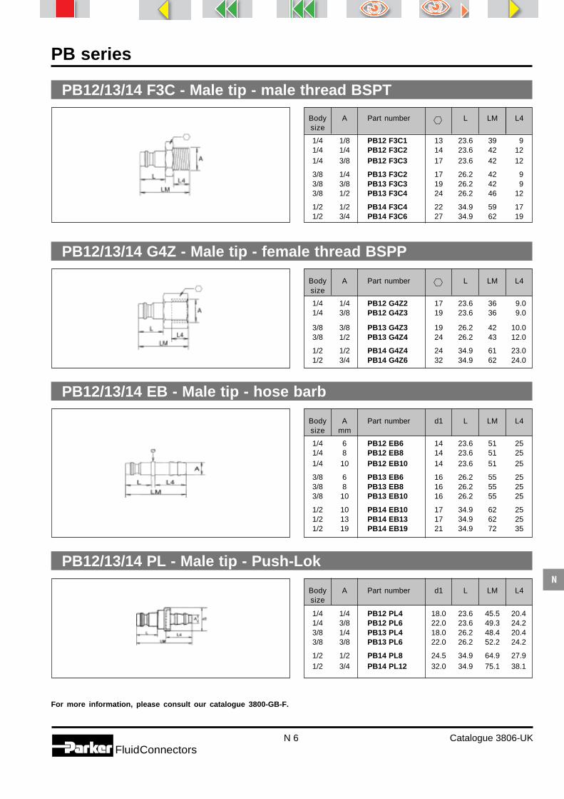
N 6 Catalogue 3806-UKFluidConnectors
N
PB series
PB12/13/14 F3C - Male tip - male thread BSPT
PB12/13/14 EB - Male tip - hose barb
PB12/13/14 PL - Male tip - Push-Lok
PB12/13/14 G4Z - Male tip - female thread BSPP
For more information, please consult our catalogue 3800-GB-F.
Body A Part number L LM L4size
1/4 1/8 PB12 F3C1 13 23.6 39 91/4 1/4 PB12 F3C2 14 23.6 42 121/4 3/8 PB12 F3C3 17 23.6 42 12
3/8 1/4 PB13 F3C2 17 26.2 42 93/8 3/8 PB13 F3C3 19 26.2 42 93/8 1/2 PB13 F3C4 24 26.2 46 12
1/2 1/2 PB14 F3C4 22 34.9 59 171/2 3/4 PB14 F3C6 27 34.9 62 19
Body A Part number L LM L4size
1/4 1/4 PB12 G4Z2 17 23.6 36 9.01/4 3/8 PB12 G4Z3 19 23.6 36 9.0
3/8 3/8 PB13 G4Z3 19 26.2 42 10.03/8 1/2 PB13 G4Z4 24 26.2 43 12.0
1/2 1/2 PB14 G4Z4 24 34.9 61 23.01/2 3/4 PB14 G4Z6 32 34.9 62 24.0
Body A Part number d1 L LM L4size mm
1/4 6 PB12 EB6 14 23.6 51 251/4 8 PB12 EB8 14 23.6 51 251/4 10 PB12 EB10 14 23.6 51 25
3/8 6 PB13 EB6 16 26.2 55 253/8 8 PB13 EB8 16 26.2 55 253/8 10 PB13 EB10 16 26.2 55 25
1/2 10 PB14 EB10 17 34.9 62 251/2 13 PB14 EB13 17 34.9 62 251/2 19 PB14 EB19 21 34.9 72 35
Body A Part number d1 L LM L4size
1/4 1/4 PB12 PL4 18.0 23.6 45.5 20.41/4 3/8 PB12 PL6 22.0 23.6 49.3 24.23/8 1/4 PB13 PL4 18.0 26.2 48.4 20.43/8 3/8 PB13 PL6 22.0 26.2 52.2 24.2
1/2 1/2 PB14 PL8 24.5 34.9 64.9 27.91/2 3/4 PB14 PL12 32.0 34.9 75.1 38.1

N 7 Catalogue 3806-UKFluidConnectors
N
PBF series
For more information, please consult our catalogue 3800-GB-F.
Principle
PBF series pneumatic quick couplersare only available in the 1/4" size andconform to specifications and profile ofISO standard 6150-B, while havingimproved flow capability.- Valving on female half only :
poppet.- Meets the requirements of
ISO 6150-B, US MIL-C4109 andAFNOR E49-053.
- End configuration : BSP male andfemale, barb connector.
- One-hand operated (Push-to-con-nect).
Applications
The PBF series comes from the same family as the PB series, but has even better flow characteristics, enablingthese couplers to be used with any type of pneumatic tool.This series can be used in place of larger size couplers, because the pressure drop has been greatly improved.
Technical features
Material
Female body
End adaptor Body Sleeve Poppet SealsMale tip
Bodysize
Flow ratesl/min.
Brassnickelplated
BrassAISI 301Stainless
steel
AISI 420Stainless
steel
NBR(Nitrile) 1/4" 900
From -20°Cto
+ 100°C
Spring andsnap ring
Balls
Brassnickelplated
Steelhardenedand nickel
plated
Hardenedsteel nickel
plated
Max.operatingpressure
16 bar
Temperaturerange

N 8 Catalogue 3806-UKFluidConnectors
N
PBF series
PBF52F3C - Female body - male thread BSPT
PBF52G4Z - Female body - female thread BSPP
PBF52 EB - Female body - hose barb
Pressure drop
Tests with air, inlet pressure 6 bar. Tests with water
Bodysize
Bodysize
Bodysize
Important : PBF series female bodies are recommended for use with PB series male tips (N 6).
For more information, please consult our catalogue 3800-GB-F.
Air flow (l/min)1/4"
200 400 600 8000
0.8
0.7
0.6
0.5
0.4
0.3
0.2
0.1
01000 1200
Pre
ssur
e dr
op (
bar)
Water flow (l/min)1/4"
10 15 20 25
4
3
2
1
00 5
Pre
ssur
e dr
op (
bar)
A Part number d1 LF L4
1/4 1/4 PBF52 F3C2 23 19 59 121/4 3/8 PBF52 F3C3 23 19 59 12
A Part number d1 LF L4
1/4 1/4 PBF52 G4Z2 23 19 55 101/4 3/8 PBF52 G4Z3 23 19 54 9
A Part number d1 LF L4mm
1/4 6 PBF52 EB6 23 19 73 251/4 8 PBF52 EB8 23 19 73 251/4 10 PBF52 EB10 23 19 73 25
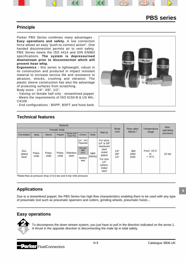
N 9 Catalogue 3806-UKFluidConnectors
N
PBS series
To decompress the down stream system, you just have to pull in the direction indicated on the arrow 1.A thrust in the opposite direction is disconnecting the male tip in total safety.
1/4"3/8”1/2”
Principle
Parker PBS Series combines many advantages :Easy operations and safety. A low connectionforce allows an easy “push-to-connect action”. Onehanded disconnection permits air to vent safety.PBS Series meets the ISO 4414 and DIN EN983specifications. The system is depressuriseddownstream prior to disconnection which willprevent hose whip.Ergonomics : this series is lightweight, robust inits construction and produced in impact resistantmaterial to increase service life and resistance toabrasion, shocks, crushing and vibration. Theplastic sleeve construction has also the advantageof protecting surfaces from scratching.Body sizes : 1/4”, 3/8”, 1/2”.- Valving on female half only : streamlined poppet- Meets the requirements of ISO 6150-B & US MIL-C4109- End configurations : BSPP, BSPT and hose barb.
Applications
Due to a streamlined poppet, the PBS Series has high flow characteristics enabling them to be used with any typeof pneumatic tool such as pneumatic spanners and cutters, grinding wheels, pneumatic hoists…
Technical features
Material
Female body
End adaptor Body Sleeve Poppet SealsMale tip
Bodysize
Flow ratesNl/min.*
Zinc platedsteel
Polya-cetal
Stainlesssteel
NBR(Nitrile)
88018004160
From -15°Cto
+ 70°C
Spring andsnap ring
Polya-mide
Polya-mide
For sizes1/4” & 3/8”Hardened
steelnickelplated
For size1/2”
carbon-tridedsteel
Max.operatingpressure
16 bar
Temperaturerange
Easy operations
*Rated flow at pressure drop of 0,6 bar and 6 bar inlet pressure.
Clamps
(1/4” - 3/8”)Polyacetal
Pins andballs(1/2”)
Stainlesssteel

N 10 Catalogue 3806-UKFluidConnectors
N
PBS series
Pressure drop
Tests with air
PBS - 251/371/501 - FB - Female body - female thread BSPP
PBS - 251/371/501 - MB - Female body - male thread BSPP
A d1
L4LF
A d1
L4LF
PBS - 251/371/501 - HB - Female body - hose barb
A d1
L4
LF
Pre
ssu
re d
rop
(b
ar)
1
0,9
0,8
0,7
0,6
0,5
0,4
0,3
0,2
0,1
00 400 600 800 1000 14001200
PBS 1/4"
Air flow (NI/min)
Pre
ssu
re d
rop
(b
ar)
1
0,9
0,8
0,7
0,6
0,5
0,4
0,3
0,2
0,1
00 400 800 1200 1600 24002000
PBS 3/8"
Air flow (NI/min)
PBS 1/2"
Air flow (NI/min)
Pre
ssu
re d
rop
(b
ar)
1
0,9
0,8
0,7
0,6
0,5
0,4
0,3
0,2
0,1
00 1000 2000 3000 4000 5000
Size A Part number d1 LF L4
1/4 1/4 PBS - 251 - 4MB 30 17 74,5 111/4 3/8 PBS - 251 - 6MB 30 23 77 123/8 3/8 PBS - 371 - 6MB 35 21 86 123/8 1/2 PBS - 371 - 8MB 35 23 89 141/2 1/2 PBS - 501 - 8MB 41 30 89 141/2 3/4 PBS - 501 - 12MB 41 30 91 16
Size A Part number d1 LF L4
1/4 1/4 PBS - 251 - 4FB 30 17 64 91/4 3/8 PBS - 251 - 6FB 30 23 71 163/8 3/8 PBS - 371 - 6FB 35 21 74 93/8 1/2 PBS - 371 - 8FB 35 25 84 191/2 1/2 PBS - 501 - 8FB 41 30 86 241/2 3/4 PBS - 501 - 12FB 41 30 95 33
Size A Part number d1 LF L4mm
1/4 6 PBS - 251 - 4HB 30 82 231/4 8 PBS - 251 - 5HB 30 82 231/4 10 PBS - 251 - 6HB 30 82 233/8 8 PBS - 371 - 5HB 35 92 233/8 10 PBS - 371 - 6HB 35 92 231/2 13 PBS - 501 - 8HB 41 109 331/2 16 PBS - 501 -10HB 41 109 33

N 11 Catalogue 3806-UKFluidConnectors
N
PBS series
Important : For size 1/4 & 3/8”, male tips to be used with PBS female bodies are those of the PB Series (page N6).For size 1/2”, please use the male tips PBS-502 with a specific treatment especially designed towithstand high flows.
PBS - 502 - FB - Male tip - female thread BSPP
PBS - 502 - MBT - Male tip - male thread BSPT
PBS - 502 - HB - Male tip - hose barb
AL4
LM
A
L4LM
A
L4
LM
Size A Part number LM L4
1/2 3/8 PBS - 502 - 6MBT 17 82 111/2 1/2 PBS - 502 - 8MBT 22 84 15
Size A Part number LM L4
1/2 3/8 PBS - 502 - 6FB 25 60 251/2 1/2 PBS - 502 - 8FB 25 60 25
Size A Part number LM L4mm
1/2 13 PBS - 502 - 8HB 70 331/2 16 PBS - 502 -10HB 69 33

N 12 Catalogue 3806-UKFluidConnectors
N
PE series
Principle
Showing the same overall dimensions ascorresponding size PB couplers, the PEseries offers the double advantage of aprofile design widespread in Europe andimproved flow performance due to alarger flow path (7.2 mm).
- Valving on female half only :poppet.
- End configuration : BSP male andfemale, barb connector, ParkerPush-Lok.
- One-hand operated (Push-to-con-nect).
Applications
Because of their flow characteristics, the PE series of couplers satisfies most pneumatic applications and caneven replace couplers of a different design, but of larger size. They are ideally used with all kinds of pneumatic handtools.
Technical features
Material
Female body
End adaptor Body Sleeve Valve SealsMale tip
Bodysize
Flow ratesl/min*
Temperaturerange
Brass BrassAISI 301Stainless
steel
AISI 420Stainless
steelhardened54HRC
NBR(Nitrile)
7.2 mm 1000 35 barFrom -20°C
to+ 100°C
Spring andsnap ring Pins
Brass Brass Brass
* Rated flow at pressure drop of 0.5 bar and 6 bar inlet pressure.
For more information, please consult our catalogue 3800-GB-F.
Max.operatingpressure

N 13 Catalogue 3806-UKFluidConnectors
N
10 15 20 25 300 5
4
3
2
1
0
PE series
PE52 F3C - Female body - male thread BSPP
PE52 G4Z - Female body - female thread BSPP
PE52 EB - Female body - hose barb
Pressure drop
Bodysizemm
Bodysizemm
Bodysizemm
For more information, please consult our catalogue 3800-GB-F.
Tests with air, inlet pressure 6 bar. Tests with water
Air flow (l/min)1/4"
200 400 600 800 0
0.8
0.7
0.6
0.5
0.4
0.3
0.2
0.1
01000 1200
Water flow (l/min)1/4"
Pre
ssur
e dr
op (
bar)
Pre
ssur
e dr
op (
bar)
A Part number d1 LF L4
7.2 1/4 PE52 F3C2 25 22 39 97.2 3/8 PE52 F3C3 25 22 41 97.2 1/2 PE52 F3C4 25 22 44 12
A Part number d1 LF L4
7.2 1/4 PE52 G4Z2 25 22 41 97.2 3/8 PE52 G4Z3 25 22 41 97.2 1/2 PE52 G4Z4 25 24 44 10
A Part number d1 LF L4mm
7.2 6 PE52 EB6 25 21 58 257.2 8 PE52 EB8 25 21 58 257.2 10 PE52 EB10 25 21 58 25

N 14 Catalogue 3806-UKFluidConnectors
N
PE series
PE12 F3C - Male tip - male thread BSPP
PE12 G4Z - Male tip - female thread BSPP
PE12 EB - Male tip - hose barb
PE12 PL - Male tip - Push-Lok
Bodysizemm
Bodysizemm
Bodysizemm
Bodysizemm
For more information, please consult our catalogue 3800-GB-F.
A Part number L LM L4
7.2 1/8 PE12 F3C1 14 20 31 97.2 1/4 PE12 F3C2 17 20 33 97.2 3/8 PE12 F3C3 19 20 33 9
A Part number L LM L4
7.2 1/4 PE12 G4Z2 17 20 33 107.2 3/8 PE12 G4Z3 19 20 33 107.2 1/2 PE12 G4Z4 24 20 35 12
A Part number Ø L LM L4mm
7.2 6 PE12 EB6 12 20 48 257.2 8 PE12 EB8 12 20 48 257.2 10 PE12 EB10 12 20 48 257.2 13 PE12 EB13 15 20 48 25
A Part number d1 L LM L4
7.2 1/4 PE12 PL4 18.0 20 42 20.47.2 3/8 PE12 PL6 22.0 20 46 24.27.2 1/2 PE12 PL8 24.5 20 50 27.9

N 15 Catalogue 3806-UKFluidConnectors
N
PEF series
Showing exceptional flow characteristics, PEF series couplers are used in all pneumatic applications, wherepressure drop has to be reduced to an absolute minimum, and energy saving is essential.
Applications
Principle
The PEF series are available in 7.2and 10 mm nominal sizes with thesame profile as PE series. However,flow characteristics are even better.
- Valving on female half only : poppet.
- End configuration : BSP male andfemale, barb connector, Parker Push-Lok.
- One-hand operated (Push-to-con-nect).
Technical featuresMaterial
Female body
End adaptor Body Sleeve Poppet SealsMale tip
Bodysize
Flow ratesl/min
Temperaturerange
Max.operatingpressure
Brassnickelplated
Brass NBR(Nitrile)
7.2 mm10 mm
18003500
16 barFrom -20°C
to+ 100°C
Spring andsnap ring
Steel hardenedand
nickel plated
Hardenedsteel nickel
plated
Brassnickelplated
Balls
Pressure drop
AISI 420Stainless
steel
AISI 301Stainless
steel
Tests with air, inlet pressure 6 bar. Tests with water
300 600 9000
0.7
0.6
0.5
0.4
0.3
0.2
0.1
01200 1500 1800 2100
5000
0.5
0.4
0.3
0.2
0.1
01000 1500 2000 2500 3000 3500
Water flow (l/min)7.2 mm
10 15 20 25 300 5
4
3
2
1
0
Water flow (l/min)10 mm
10 20 30 40 50 60 700
4
3
2
1
0
Pre
ssur
e dr
op (
bar)
Air flow (l/min)7.2 mm
Pre
ssur
e dr
op (
bar)
Air flow (l/min)10 mm
Pre
ssur
e dr
op (
bar)
Pre
ssur
e dr
op (
bar)

N 16 Catalogue 3806-UKFluidConnectors
N
PEF series
PEF52/53 F3C - Female body - male thread BSPT
PEF52/53 G4Z - Female body - female thread BSPP
PEF52/53 EB - Female body - hose barb
Bodysizemm
Bodysizemm
Bodysizemm
For more information, please consult our catalogue 3800-GB-F.
A Part number d1 LF L4
7.2 1/4 PEF52 F3C2 23 19 60 127.2 3/8 PEF52 F3C3 23 19 60 127.2 1/2 PEF52 F3C4 23 22 61 17
10.0 3/8 PEF53 F3C3 27 24 63 1210.0 1/2 PEF53 F3C4 27 24 65 17
A Part number d1 LF L4
7.2 1/4 PEF52 G4Z2 23 19 56 107.2 3/8 PEF52 G4Z3 23 19 55 97.2 1/2 PEF52 G4Z4 23 24 58 12
10.0 3/8 PEF53 G4Z3 27 24 56 1110.0 1/2 PEF53 G4Z4 27 24 56 12
A Part number d1 LF L4mm
7.2 6 PEF52 EB6 23 19 74 257.2 8 PEF52 EB8 23 19 74 257.2 10 PEF52 EB10 23 19 74 25
10.0 6 PEF53 EB6 27 24 76 2510.0 8 PEF53 EB8 27 24 76 2510.0 10 PEF53 EB10 27 24 76 2510.0 13 PEF53 EB13 27 24 76 25

N 17 Catalogue 3806-UKFluidConnectors
N
PEF series
PEF12/13 F3C - Male tip - male thread BSPT
PEF12/13 G4Z - Male tip - female thread BSPP
PEF12/13 EB - Male tip - hose barb
PEF12/13 PL - Male tip - Push-Lok
Bodysizemm
Bodysizemm
Bodysizemm
Bodysizemm
For more information, please consult our catalogue 3800-GB-F.
A Part number Ø L LM L4mm
7.2 6 PEF12 EB6 12 20.0 48 257.2 8 PEF12 EB8 12 20.0 48 25
7.2 10 PEF12 EB10 12 20.0 48 25
10.0 6 PEF13 EB6 15 21.5 48 2510.0 8 PEF13 EB8 15 21.5 48 2510.0 10 PEF13 EB10 15 21.5 48 2510.0 13 PEF13 EB13 15 21.5 48 25
A Part number d1 L LM L4
10 1/4 PEF13 PL4 18 21.5 44.0 20.410 3/8 PEF13 PL6 22 21.5 47.8 24.2
A Part number L LM L4
7.2 1/4 PEF12 G4Z2 17 20.0 33 97.2 3/8 PEF12 G4Z3 19 20.0 33 97.2 1/2 PEF12 G4Z4 24 20.0 36 12
10.0 3/8 PEF13 G4Z3 19 21.5 33 910.0 1/2 PEF13 G4Z4 24 21.5 37 12
A Part number L LM L4
7.2 1/8 PEF12 F3C1 13 20.0 33 97.2 1/4 PEF12 F3C2 14 20.0 37 127.2 3/8 PEF12 F3C3 17 20.0 37 127.2 1/2 PEF12 F3C4 22 20.0 43 17
10.0 1/4 PEF13 F3C2 17 21.5 40 1210.0 3/8 PEF13 F3C3 17 21.5 40 1210.0 1/2 PEF13 F3C4 22 21.5 45 17

N 18 Catalogue 3806-UKFluidConnectors
N
PES series
Principle
Parker PES Series combines many advantages :Easy operations and safety. A low connectionforce allows an easy “push-to-connect action”. Onehanded disconnection permits air to vent safety.PES Series meets the ISO 4414 and DIN EN983specifications. The system is depressuriseddownstream prior to disconnection which willprevent hose whip.Ergonomics : this series is lightweight, robust inits construction and produced in impact resistantmaterial to increase service life and resistance toabrasion, shocks, crushing and vibration. Theplastic sleeve construction has also the advantageof protecting surfaces from scratching.Body size : 7.2 mm.- Valving on female half only : streamlined poppet- Meets the requirements of “Europrofile”- End configurations : BSPP, BSPT and hose barb.
Applications
Due to a streamlined poppet, the PES Series has high flow characyeristics enabling them to be used with any typeof pneumatic tool such as pneumatic spanners and cutters, grinding wheels, pneumatic hoists…
Technical features
Material
Female body
End adaptor Body Sleeve Poppet SealsMale tip
Bodysize
Flow ratesNl/min.*
Zinc platedsteel
Polya-cetal
Stainlesssteel
NBR(Nitrile)
1470From -15°C
to+ 70°C
Spring andsnap ring
Polya-mide
Polya-mide
carbon-tridedsteel
Max.operatingpressure
16 bar
Temperaturerange
Easy operations
*Rated flow at pressure drop of 0,6 bar and 6 bar inlet pressure.
7.2 mm
To decompress the down stream system, you just have to pull in the direction indicated on the arrow 1.A trust in the opposite direction is disconnecting the male tip in total safety.
Pins andballs
Stainlesssteel

N 19 Catalogue 3806-UKFluidConnectors
N
PES series
Pressure drop
Tests with air
PES - 251 - FB - Female body - female thread BSPP
PES 7.2 mm
Air flow (NI/min)
Pre
ssu
re d
rop
(b
ar)
1
0,9
0,8
0,7
0,6
0,5
0,4
0,3
0,2
0,1
00 400 800 1200 1600 2000
PES - 251 - MB - Female body - male thread BSPP
A Part number d1 LF L4
7.2 1/4 PES - 251 - 4MB 32 21 71 227.2 3/8 PES - 251 - 6MB 32 21 72 23A d
1
L4LF
Sizemm
Sizemm
A d1
L4LF
A Part number d1 LF L4
7.2 1/4 PES - 251 - 4FB 32 21 60 117.2 3/8 PES - 251 - 6FB 32 21 60 11
PES - 251 - HB - Female body - hose barbSizemm A Part number d1 LF L4
7.2 6 PES - 251 - 4HB 32 78 297.2 8 PES - 251 - 5HB 32 78 297.2 10 PES - 251 - 6HB 32 78 29
A d1
L4
LF
Important : Male tips to be used with PES female bodies are those of the PEF Series (page N15).

N 20 Catalogue 3806-UKFluidConnectors
N
Principle
The PCF series, available in the 1/4"body size, has been designed tomeet the profile defined in ISOstandard 6150-C. It has very goodflow capability.- Valving on female half only :
poppetMeets the requirements of ISO 6150-C
- End configuration : BSP male andfemale, barb connector
- One-hand operated (Push-to-connect)
Material
Female body
Body Sleeve Poppet Seals
Temperaturerange
Max.operatingpressure
Brassnickelplated
Brassnickelplated
Steelhardened
andnickelplated
AISI 301Stainless
steel
AISI 420Stainless
steel
NBR(Nitrile)
1/4" 970 15 barFrom -20 °C
to+ 100 °C
Spring andsnap ring
BallsEnd adaptorMale tip
Bodysize
Flow ratesl/min
For more information, please consult our catalogue 3800-GB-F.
Applications
The 1/4" size PCF series pneumatic couplers are extensively used in the connection of pneumatic tools currentlyutilised in industry.
Hardenedsteel,nickelplated
Brass
Technical features
PCF series

N 21 Catalogue 3806-UKFluidConnectors
N
PCF series
Pressure drop
PCF52F3C - Female body - male thread BSPT
PCF52G4Z - Female body - female thread BSPP
PCF52EB - Female body - hose barb
Bodysize
Bodysize
Bodysize
Tests with air, inlet pressure 6 bar. Tests with water
For more information, please consult our catalogue 3800-GB-F.
Air flow (l/min)
0,7
0,6
0,5
0,4
0,3
0,2
0,1
0
00 200 400 600 800 1000 1200
Pre
ssur
e dr
op (
bar)
Water flow (l/min)
0
0,5
1
1,5
2
2,5
3
3,5
4
0 5 10 15 20 25 30 35
Pre
ssur
e dr
op (
bar)
A Part number d1 LF L4
1/4 1/4 PCF52F3C2 23 19 63 121/4 3/8 PCF52F3C3 23 19 63 121/4 1/2 PCF52F3C4 23 22 68 17
A Part number d1 LF L4
1/4 1/4 PCF52G4Z2 23 19 58 91/4 3/8 PCF52G4Z3 23 19 57 91/4 1/2 PCF52G4Z4 23 24 60 12
A Part number d1 LF L4mm
1/4 6 PCF52EB6 23 19 76 251/4 8 PCF52EB8 23 19 76 251/4 10 PCF52EB10 23 19 76 25

N 22 Catalogue 3806-UKFluidConnectors
N
PCF series
PCF12F3C - Male tip - male thread BSPT
PCF12G4Z - Male tip - female thread BSPP
PCF12EB - Male tip - hose barb
Bodysize
Bodysize
For more information, please consult our catalogue 3800-GB-F.
A Part number L LM L4
1/4 1/4 PCF12F3C2 17 27.5 41 91/4 3/8 PCF12F3C3 19 27.5 41 9
A Part number L LM L4
1/4 1/4 PCF12G4Z2 17 27.5 40 91/4 3/8 PCF12G4Z3 19 27.5 41 9
Bodysize
A Part number Ø L LM L4mm
1/4 6 PCF12EB6 12 27.5 59 251/4 8 PCF12EB8 12 27.5 59 251/4 10 PCF12EB10 12 27.5 59 25

N 23 Catalogue 3806-UKFluidConnectors
N
BG series
Principle
The blow guns of the BG Series areavailable with a variety of nozzleconfigurations. They combine manyadvantages : light weight, reducednoise level, easy control, ergonomicdesign and variable flow, thusproviding superior performance.- Standard : nozzles available that
meet OSHA requirements- Inlet port : 1/4” NPTF and 1/4”
BSPP
Technical features
Applications
BG Series blow guns can be used at all the manufacturing stages to :- blow off parts- clean work-stations- remove dust- dry
Material :Impact resistant plastic.
Pistol grip trigger :Allows greater control over the amount of air delivered.
Dual hooks for hanging.Ergonomic lever :For an easy, instantaneous handling, without effort.
Nozzles :- extended nozzles allow air to be focused where it isneeded- short nozzles also available.
Standards :Most models meet OSHA directives on the use ofcompressed air for cleaning purposes. OSHA directive
#100-1 states that “when dead ending occurs a staticpressure at the main orifice shall not exceed 2 bar”. Forthose blow guns that do not meet this requirement,OSHA requires that “compressed air shall not be usedfor cleaning purposes except where reduced to lessthan 2 bar, and then only with effective chip guardingand personal protective equipment” (section 29 CFR1910.242 paragraph b). Please refer to the blow gundescriptions on the next page for compatibility withOSHA directive #100-1.
Temperature range Rated pressure (bar)
–20 °C +50 °C 12

N 24 Catalogue 3806-UKFluidConnectors
N
BG series
Thread Description Meets OSHA requirements Colour Part Numberyes no black grey
Blow Guns
Thread Description Meets OSHA requirements Colour Part Numberyes no black grey
1/4 NPTF Extended nozzle • • BG442-SBL1/4 NPTF Extended nozzle • • BG442-SGY1/4 NPTF Extended nozzle • • BG441-NBL1/4 NPTF Short nozzle • • BG444-SBL1/4 NPTF 1/8” female NPT • • BG443-NBL
thread
1/4 BSPP Extended nozzle • • BG342-SBL1/4 BSPP Extended nozzle • • BG341-NBL1/4 BSPP Short nozzle • • BG344-SBL

Catalogue 4482-UK
Push-Lok®
Hoses & Fittings

O 2 Catalogue 4482-UKFluidConnectors
O
Index
801 - Push-Lok® Hose for low pressure applications 6804 - Push-Lok® Hose for Phosphate ester Fluids 6821 - Push-Lok® Hose with textile braided outer cover 7821FR - Push-Lok® Hose with Fire-resistant cover 7831 - Push-Lok® Hose for all standard industrial applications 8836 - Push-Lok® Hose for high Oil Temperatures 8837BM- Push-Lok® for standard applications in the automotive industry 9
Hoses
Fittings Page Fittings Page
30182 - NPTF Male Pipe 2130282 - Female NPTF Pipe 2230382 - JIC 37° Male 2230682 - JIC 37° Swivel Female 2330882 - SAE 45° Swivel female 2431382 - NPTF Swivel Male Pipe 2231D82 - Metric Standpipe Light Series 1533482 - Inch Standpipe (Brass) 2033782 - JIC 37° Swivel Female 45° Elbow 2333982 - JIC 37° Swivel Female 90° Elbow 2434182 - JIC 37° Swivel Female 90° Elbow 2434982 - Banjo Union DIN 7642 2835C82 - 60°-90° Cone Swivel Female 1536C82 - 60°-90° Cone Swivel Female 1637782 - SAE 45° swivel female 45° elbow 2537982 - SAE 45° swivel female 90° elbow 2537C82 - 60°-90° Cone Swivel Female 1638282 - Push-Lok® Union 2939182 - BSP Taper Male 2039282 - BSP Swivel Female 1839B82 - DIN 20 078 A Light Series Metric
Swivel Female 45° Elbow 1239C82 - DIN 20 078 A Light Series
Metric Swivel Female 90° Elbow 123AF82 - Male BSP Parallel Pipe - Rigid
Straight (with O-Ring Seal) 313B182 - BSP Swivel Female 45° Elbow 193B282 - BSP Swivel Female 90° Elbow 193C082 - DIN 20 078 C Very Light Series Metric
Swivel Female 143C382 - DIN 20 078 A Light Series Metric
Swivel Female 103C482 - DIN 20 078 A Light Series Metric
Swivel Female 45° Elbow 113C582 - DIN 20 078 A Light Series Metric
Swivel Female 90° Elbow 113CA82 - DIN 20 078 N Light Series Metric
Swivel Female 13
3CE82 - DIN 20 078 N Light Series MetricSwivel Female 45° Elbow 13
3CF82 - DIN 20 078 N Light Series MetricSwivel Female 45° Elbow 14
3D082 - DIN 20 078 D Light Series Male Stud 143D982 - BSP Male Stud (Form A) 193DE82 - Double Banjo Union 283DP82 - Metric Swivel Female Tee / Male Stud 173DR82 - Metric Swivel Female Tee 183DS82 - Metric Swivel Female Tee / Standpipe 183EG82 - Straight Adaptor 163EV82 - 45° Elbow Adaptor 173EW82- 90° Elbow Adaptor 173FB82 - French Metric 273FF82 - Metru-Lok Swivel Female 273J182 - ORFS Swivel Female 90° Elbow 263J782 - ORFS Swivel Female 45° Elbow 263J982 - ORFS Swivel Female 90° Elbow 263JC82 - ORFS Swivel Female (Short) 253JM82 - ORFS Male 263VW82- Push-in Connector (VW Standard 39-V-16619) 29AM/AR - Banjo Bolt (DIN 7643) 29H897995 - Female (Ford Standard UWR 003-03180) 30H898202 - Male (Ford Standard UWR 003-03180) 30M14-4C3MX8BH22 - Male nipple 90° elbow
(Ford Standard UWR 003-04180) 31M14-4C63MX8BH22 - Male swivel nut 90° elbow
(Ford Standard UWR 003-04180) 32M14-4F3MX8BL31 - Male nipple straight fitting
(Ford Standard UWR 003-04180) 31M14-4F63MX8BL32 - Male swivel nut straight fitting
(Ford Standard UWR 003-04180) 32M14-4V3MX8BH17 - Male nipple 45° elbow
(Ford Standard UWR 003-04180) 31M14-4V63MX8BH17 - Male swivel nut 45° elbow
(Ford Standard UWR 003-04180) 32VW121 - BSP Swivel Female (VW Standard 39-V-16631) 30VW39D - VW-Push In Connector (VW Standard 39D-1401) 30
Push-Lok® Hoses and fittings

O 3 Catalogue 4482-UKFluidConnectors
O
Index
Push-Lok® Hoses and fittings
For your safety !Flexible hoses are used to transmit fluids, sometimes at considerable pressures. The power-grip connection between the fittingand the hose is a critical zone in all flexible hose connections. Only use Parker components (hoses and nipples) designed to beassembled by means of the appropriate Parker tooling, which will ensure full compliance with standards. Following installationrecommendations and suitable maintenance also give a guarantee for long life of the flexible hose. Non-compliance with theseelementary rules can lead to the rupture of a flexible hose and cause considerable damage and sometimes bodily injury.
Assembly instructions 5Push-Lok® cut off and assembly tools 5
Assembly Accessories Page
Chemical resistance 33 - 36

O 4 Catalogue 4482-UKFluidConnectors
O
Push-Lok®: an effective cost saving hose
Colour coding, a valuable Push-Lok® hose advantage
801 - hose is manufactured in grey, black,red and green.
804 - hose is manufactured in black.821 - hose is manufactured in black.821FR - hose is manufactured in black,
blue, green and white.831 - hose is manufactured in black,
blue, green and red.836 - hose is manufactured in blue.837BM - hose is manufactured in black,
blue, green, red and grey.
• Easy and fast identification of hose lines, wheremany hoses carry different fluids (e.g. oil, water, air,solutions, etc.)
• Immediate control and/or replacement of hoseassemblies due to specific colours for diameters andlengths.
• Easy preventive maintenance
• Reduced maintenance time, when colours identifyspecific maintenance periods
Please put the colour code at the end of your part number to get the correct hose.
GRA(GREY)
Push-Lok® Hoses and fittings
Fibre braid reinforcement layeris impregnated with syntheticrubber for added durability
High-quality elastomer cover -excellent flexibility and resistanceto abrasion
Extruded synthetic rubber.Inner liner is resistant topetroleum-based oil, airand water
RED(RED)
BLK(BLACK)
WHT(WHITE)
BLU(BLUE)
GRN(GREEN)
ORA(ORANGE)
BRN(BROWN)

O 5 Catalogue 4482-UKFluidConnectors
O
Assembly toolTool designed for assembly of Push-Lok® fittings and hose in allsizes. Toggle actions greatly reduce effort necessary to hold hoseand press in fitting. Only a few pounds of force are needed oneither handle to quickly assemble any size.Overall length: 320 mmWeight: 2,2 kg
Part No. 611050G
Push-Lok® disassembly instructions
1. Cut the hose right angled witha sharp knife. If necessary it ispossible to use a lubricant (water/soap solution with 5% soap fluidand 95% water) for easyassembly (exception 837BM).
1. Cut lengthwise along a line atapproximately a 20° angle fromcentre line of hose. The cutshould be approximately 1" long.Be careful not to nick barbs whencutting the hose.
2. Insert fitting into hoseuntil first barb is in hose.Place end of fitting againsta flat object (bench, door,wall) and grip hoseapproximately 1" from endand push with a steadyforce until end of hose iscovered by the yellowplastic collar. Alternativelyplease use the ParkerAssembly Tool No.611050G.
Attention! During assembly please note that Push-Lok® fittings will provide an effective grip only when the Push-Lok® hose ispushed fully on the insert, where the cropped end of the hose should be fully concealed by the plastic collar. For easy assemblyof hose 837BM please use only Push-Lok® Assembly Oil No. H896137. Push-Lok® Assembly Oil is free from wetting disturbingsubstances. Don´t use oil, lubricant or soap fluids for this hose!
2. Grip hose and give asharp downward tug todisengage from fitting.
Attention! Before re-use of the nipple please check nipple for damage. Damaged nipples can cause leakage.
Push-Lok® assembly instructions
Push-Lok® assembly oil H896137Water-oil emulsion for easier assembly of Parker Push-Lok® fittings. This product is very useful in combination with 837BM hose(labs-free). Our Push-Lok® assembly oil is also free from wetting disturbing substances, like e.g. silicone.
1-litre bottle Part No. H896137
Push-Lok® Hoses and fittings

O 6 Catalogue 4482-UKFluidConnectors
O
801 - Push-Lok® Hose for low pressure applications
*1 = the vacuum values listed in the table are vacuum pressure values in kPa. For an absolute value subtract the table value from 101kPaNote: when ordering, specify Push-Lok® hose part number, followed by size, followed by colour. Example: 801-4-XXX-RLXXX = BLK = black BLU = blue RED = red GRN = green GRA = greyExample: 801-4-GRN-RL (green) RL = only available on reels 801-16-RL is only available in grey.
Hose construction : EPDM synthetic rubber tube; a single fibre braid reinforcementand a black, EPDM synthetic rubber cover.
Fluid compatibility : Water, water glycol emulsions, air, phosphate ester basedhydraulic fluids. Do not allow tube to contact any petroleum based fluids. Use liquidsoap as lubricant. Further details are listed in the chemical chart.
Temperature range:Phosphate ester Hydraulic fluids ................................................... -40 °C to +80 °CExceptions: Air .................................................................................. max.+70 °C
Water ............................................................................ max. +93 °C
Applications : Low pressure service hose ideally suited for general pneumaticapplications (including dry air), water, water-glycol and phosphate ester based hydraulicfluids.
Restrictions : Not recommended for compressed air brakes, transportation offlammable gases, hydraulic or other applications where extreme pulsations areencountered. Also not recommended for thyristor cooling applications.
Fittings: 82 series
Push-Lok® Hoses and fittings
Hose construction : Synthetic rubber tube; one fibre braid reinforcement; oil andweather resitant synthetic rubber cover.
Fluid compatibility : Mineral based hydraulic and lubricating oils, coolant, antifreeze,air, water and water-oil emulsions. Further details are listed in the chemical chart.
Temperature range : ..................................................................... -40 °C/+100 °CExceptions : .................................................................................. Air max. +70 °CWater max. .................................................................................................+85 °C
Applications : Low pressure shopfloor air systems, pneumatic systems and generalindustrial and maintenance applications.
Restrictions : Not recommended for compressed air brakes, transportation offlammable fluids, hydraulic or other applications where extreme pulsations areencountered. Also not recommended for thyristor cooling applications. Notrecommended for fuel lines.
Fittings: 82 series
VacuumKilo
Pascal*1
PartNumber
DNHose-I.D.
Inch Size mm
HoseO.D.mm MPa
Max. dynamicworking pressure
psi
Min. burstpressure
psiWeightkg/m
Min. bendradius
mm
Pressure rating
801-4-XXX-RL 6 1/4 -4 6.3 12.7 1.7 250 6.8 1000 95 65 0.13801-6-XXX-RL 10 3/8 -6 9.5 15.9 1.7 250 6.8 1000 95 75 0.16801-8-XXX-RL 12 1/2 -8 12.7 19.8 1.7 250 6.8 1000 95 130 0.27801-10-XXX-RL 16 5/8 -10 15.9 23.0 1.7 250 6.8 1000 51 150 0.28801-12-XXX-RL 20 3/4 -12 19.1 26.2 1.7 250 6.8 1000 51 180 0.36
801-16-RL 25 1 -16 25.4 32.5 1.2 175 4.8 700 51 250 0.55
MPa
804 - Push-Lok® Hose for Phosphate ester Fluids
PartNumber
DNHose-I.D.
Inch Size mm
HoseO.D.mm MPa
Max. dynamicworking pressure
psi
Min. burstpressure
psiWeightkg/m
Min. bendradius
mm
Pressure rating
804-4-RL 6 1/4 -4 6.3 12.7 0.9 125 3.4 500 65 0.13804-6-RL 10 3/8 -6 9.5 15.9 0.9 125 3.4 500 75 0.16804-8-RL 12 1/2 -8 12.7 19.8 0.9 125 3.4 500 130 0.27804-12-RL 20 3/4 -12 19.1 26.2 0.9 125 3.4 500 180 0.36
MPa
RL = only available on reels
Only items priced in current price list are carried in stock.

O 7 Catalogue 4482-UKFluidConnectors
O
Push-Lok® Hoses and fittings
821 - Push-Lok® Hose with textile braided outer coverHose construction : Synthetic rubber tube; one textile braid reinforcement; abrasion,oil and weather resistant black textile braided cover
Fluid compatibility : Mineral based hydraulic and lubricating oils, coolant, antifreeze,water, water-oil emulsions. Further details are listed in the chemical chart.Temperature range : .................................................................... -40 °C/+100 °CExceptions : Air ................................................................................ max. +70 °C
Water ........................................................................... max. +85 °C
Applications : Shopfloor air systems and general industrial, maintenance andautomotive applications for air, water, lubricating oils and antifreeze.
Restrictions : Not recommended for compressed air brakes, transportation offlammable fluids, hydraulic or other applications where extreme pulsations areencountered. Also not recommended for thyristor cooling applications. Notrecommended for fuel lines.
Fittings : 82 series
VacuumKilo
Pascal*1
Partnumber
DNHose-I.D.
Inch Size mm
HoseO.D.mm MPa
Max. dynamicworking pressure
psi
Min. burstpressure
psiWeightkg/m
Min. bendradius
mm
Pressure rating
821-4 6 1/4 -4 6.3 12.7 2.4 350 10.0 1400 95 65 0.07821-6 10 3/8 -6 9.5 15.9 2.0 300 8.0 1200 95 75 0.13821-8 12 1/2 -8 12.7 19.8 2.0 300 8.0 1200 95 130 0.18821-10 16 5/8 -10 15.9 23.0 1.7 250 7.0 1000 95 150 0.28821-12 20 3/4 -12 19.1 26.2 1.7 250 7.0 1000 95 180 0.31
MPa
*1 = the vacuum values listed in the table are vacuum pressure values in kPa. For an absolute value subtract the table value from 101kPaReels (RL) available upon request.
821FR - Push-Lok® Hose with Fire-resistant coverHose construction : Synthetic rubber tube; one fibre braid reinforcement; weld spark,oil- and mildew resistant black, blue, green, white or brown fibre braided cover.
Fluid compatibility : Mineral based hydraulic and lubricating oils, coolant, antifreeze,water, water-oil emulsions. Further details are listed in the chemical chart.
Temperature range : ..................................................................... -40 °C/+100 °CAir ...................................................................................................... max. +70 °CWater ................................................................................................. max. +85 °C
Applications : Compressed air systems, general industrial, maintenance andautomotive applications. Suitable in welding areas where sparks are prevalent.
Restrictions : Not recommended for compressed air brakes, transportation offlammable fluids, hydraulic or other applications where extreme pulsations areencountered. Also not recommended for thyristor cooling applications. Notrecommended for fuel lines.Fittings : 82 series
VacuumKilo
Pascal*1DNHose-I.D.
Inch Size mm
HoseO.D.mm MPa
Max. dynamicworking pressure
psi
Min. burstpressure
psiWeightkg/m
Min. bendradius
mm
Pressure rating
821FR-4-XXX-RL 6 1/4 -4 6.3 12.7 2.4 350 9.7 1400 95 65 0.12821FR-6-XXX-RL 10 3/8 -6 9.5 15.9 2.0 300 8.3 1200 95 75 0.16821FR-8-XXX-RL 12 1/2 -8 12.7 19.8 2.0 300 8.3 1200 95 130 0.18821FR-12-XXX-RL 20 3/4 -12 19.0 26.2 1.7 250 6.8 1000 95 180 0.33
MPa
*1 = the vacuum values listed in the table are vacuum pressure values in kPa. For an absolute value subtract the table value from 101kPaNote: when ordering, specify Push-Lok® hose part number, followed by size, followed by colour. Example: 821FR-4-XXX-RLXXX = BLK = black BLU = blue GRN = green WHT =white BRN = brownExample: 821FR-4-GRN-RL (green) RL = only available on reels
Only items priced in current price list are carried in stock.
Partnumber

O 8 Catalogue 4482-UKFluidConnectors
O
Push-Lok® Hoses and fittings
831 - Push-Lok® Hose for all standard industrial applications
*1 = the vacuum values listed in the table are vacuum pressure values in kPa. For an absolute value subtract the table value from 101kPaNote: when ordering, specify Push-Lok® hose part number, followed by size, followed by colour. Example: 831-4-XXX-RLXXX = BLK = black BLU = blue RED = red GRN = greenExample: 831-4-GRN-RL (green) RL = only available on reels
Hose construction : Synthetic rubber tube; one fibre braid reinforcement; black,green, blue or red oil and weather resistant synthetic rubber cover.
Fluid compatibility : Mineral based hydraulic and lubricating oils, coolant, antifreeze,water, water-oil emulsions. Further details are listed in the chemical chart.
Temperature range : ..................................................................... -40 °C/+100 °CAir ...................................................................................................... max. +70 °CWater ................................................................................................. max. +85 °C
Applications : Low pressure shopfloor air systems, pneumatic systems and generalindustrial, maintenance and automotive applications.
Restrictions : Not recommended for compressed air brakes, transportation offlammable fluids, hydraulic or other applications where extreme pulsations areencountered. Also not recommended for thyristor cooling applications. Notrecommended for fuel lines.
Fittings : 82 series
VacuumKilo
Pascal*1DNHose-I.D.
Inch Size mm
HoseO.D.mm MPa
Max. dynamicworking pressure
psi
Min. burstpressure
psiWeight
Min. bendradius
Pressure rating
831-4-XXX-RL 6 1/4 -4 6.3 12.7 2.4 350 9.7 1400 95 65 0.13831-6-XXX-RL 10 3/8 -6 9.5 15.9 2.0 300 8.3 1200 95 75 0.16831-8-XXX-RL 12 1/2 -8 12.7 19.8 2.0 300 8.3 1200 95 130 0.27831-10-XXX-RL 16 5/8 -10 15.9 23.0 2.0 300 8.3 1200 51 150 0.28831-12-XXX-RL 20 3/4 -12 19.1 26.2 2.0 300 8.3 1200 51 180 0.36
MPa
Partnumber
836 - Push-Lok® Hose for high Oil Temperatures
VacuumKilo
Pascal*1DNHose-I.D.
Inch Size mm
HoseO.D.mm MPa
Max. dynamicworking pressure
psi
Min. burstpressure
psiWeightkg/m
Min. bendradius
mm
Pressure rating
836-4-RL 6 1/4 -4 6.3 12.7 1.7 250 6.8 1000 95 65 0.13836-6-RL 10 3/8 -6 9.5 15.7 1.7 250 6.8 1000 95 75 0.16836-8-RL 12 1/2 -8 12.7 19.8 1.7 250 6.8 1000 95 130 0.27836-10-RL 16 5/8 -10 15.9 23.1 1.7 250 6.8 1000 51 150 0.28
MPa
Partnumber
Hose construction : PKR® elastomer tube; one fibre braid reinforcement; bluePKR® elastomer cover, with an embossed layline for permanent identification.Fluid compatibility : Mineral based hydraulic and lubricating oils, coolant,antifreeze, water, water-oil emulsions. Further details are listed in the chemicalchart.Temperature range : .............................................................. -40 °C/+150 °CAir ................................................................................................. max. +70 °CWater: ........................................................................................... max. +85 °CApplications : Industrial machinery and engine compartments with highoperating temperature level, shopfloor air systems, and widespread industrialand maintenance applications.Restrictions : Not recommended for compressed air brakes, transportation offlammable fluids, hydraulic or other applications where extreme pulsations areencountered. Also not recommended for thyristor cooling applications. Notrecommended for fuel lines.Fittings : 82 series
*1 = the vacuum values listed in the table are vacuum pressure values in kPa. For an absolute value subtract the table value from 101kPaRL = only available on reels
Only items priced in current price list are carried in stock.

O 9 Catalogue 4482-UKFluidConnectors
O
Only items priced in current price list are carried in stock.
Push-Lok® Hoses and fittings
837BM - Labs-free with abrasion resistant cover (for standard applications in the automotive industry)
*1 = the vacuum values listed in the table are vacuum pressure values in kPa. For an absolute value subtract the table value from 101kPaNote: when ordering, specify Push-Lok® hose part number, followed by size, followed by colour. Example: 837BM-4-XXX-RLXXX = BLK = black BLU = blue RED = red GRN = green GRA = greyExample: 837BM-4-GRN-RL (green)RL = only available on reels
Hose construction : Synthetic rubber tube; one fibre braid reinforcement; highlyabrasion and weather resistant black, grey, green, blue or red synthetic rubbercover. This hose is free of any wetting disturbing substances eg: siliconeFluid compatibility : Mineral based hydraulic and lubricating oils, coolant,antifreeze, water*, water*-oil emulsions. Further details are listed in the chemicalchart.Temperature range : ................................................................. -40 °C/+100 °CAir: ................................................................................................. max. +70 °CWater*: ........................................................................................... max. +85 °CApplications : The hose meets the automotive industry's requirement to be freefrom wetting disturbing substances. Suitable for robot lines, paint spraying airsupply lines, pneumatic systems and general industrial applications.Restrictions : Not recommended for compressed air brakes, transportation offlammable gases, hydraulic or other applications where extreme pulsations areencountered. Also not recommended for thyristor cooling applications.Fittings : 82 seriesNote : for assembly see notes on page 5.
VacuumKilo
Pascal*1DNHose-I.D.
Inch Size mm
HoseO.D.mm MPa
Max. dynamicworking pressure
psi
Min. burstpressure
psiWeightkg/m
Min. bendradius
mm
Pressure rating
837BM-4-XXX-RL 6 1/4 -4 6.3 12.7 2.4 350 9.7 1400 95 65 0.13837BM-6-XXX-RL 10 3/8 -6 9.5 15.9 2.0 300 8.3 1200 95 75 0.16837BM-8-XXX-RL 12 1/2 -8 12.7 19.8 2.0 300 8.3 1200 95 130 0.27837BM-10-XXX-RL 16 5/8 -10 15.9 23.0 2.0 300 8.3 1200 51 150 0.28837BM-12-XXX-RL 20 3/4 -12 19.1 26.2 2.0 300 8.3 1200 51 180 0.36
MPa
Partnumber

O 10 Catalogue 4482-UKFluidConnectors
Push-Lok® Hoses and fittings
O
For hose types: 801 / 804 / 821 / 821FR / 831 / 836 / 837BMOnly items priced in current price list are carried in stock.Dimensions shown may be changed at any time without prior notice.
B
W
A
B and BK parts have brass nipples and steel nuts.
3C382-6-4 6 1/4 -4 6.3 M12x1.5 6 33 15 143C382-6-4B 6 1/4 -4 6.3 M12x1.5 6 33 14 143C382-6-4BK 6 1/4 -4 6.3 M12x1.5 6 33 14 143C382-6-4C 6 1/4 -4 6.3 M12x1.5 6 35 16 143C382-8-4 6 1/4 -4 6.3 M14x1.5 8 33 14 17
3C382-8-4B 6 1/4 -4 6.3 M14x1.5 8 36 16 193C382-8-4BK 6 1/4 -4 6.3 M14x1.5 8 36 16 193C382-8-4C 6 1/4 -4 6.3 M14x1.5 8 33 14 173C382-10-4 6 1/4 -4 6.3 M16x1.5 10 34 15 193C382-10-4BK 6 1/4 -4 6.3 M16x1.5 10 34 15 19
3C382-10-4C 6 1/4 -4 6.3 M16x1.5 10 36 17 193C382-10-6 10 3/8 -6 9.5 M16x1.5 10 38 15 193C382-10-6B 10 3/8 -6 9.5 M16x1.5 10 38 15 193C382-10-6BK 10 3/8 -6 9.5 M16x1.5 10 38 15 193C382-10-6C 10 3/8 -6 9.5 M16x1.5 10 40 17 19
3C382-12-6 10 3/8 -6 9.5 M18x1.5 12 38 16 223C382-12-6BK 10 3/8 -6 9.5 M18x1.5 12 38 16 223C382-12-6C 10 3/8 -6 9.5 M18x1.5 12 38 15 223C382-15-8 12 1/2 -8 12.7 M22x1.5 15 42 15 273C382-15-8B 12 1/2 -8 12.7 M22x1.5 15 42 15 27
3C382-15-8BK 12 1/2 -8 12.7 M22x1.5 15 42 15 273C382-15-10 16 5/8 -10 15.9 M22x1.5 15 56 20 273C382-18-10 16 5/8 -10 15.9 M26x1.5 18 53 17 323C382-18-10C 16 5/8 -10 15.9 M26x1.5 18 54 17 323C382-22-12 20 3/4 -12 19.0 M30x2 22 53 17 36
3C382-22-12B 20 3/4 -12 19.0 M30x2 22 53 17 363C382-22-12BK 20 3/4 -12 19.1 M30x2 22 53 17 363C382-28-16 25 1 -16 25.4 M36x2 28 58 22 413C382-28-16BK 25 1 -16 25.4 M36x2 28 58 22 413C382-28-16-K 25 1 -16 25.4 M36x2 28 58 20 41
3C382-28-16C-K 25 1 -16 25.4 M36x2 28 58 20 41
Hose-I.D.
C3 - DIN 20 078 A Light Series Metric
TubePart Thread O.D. A B W
Number DN Inch Size mm metric mm mm mm mm
Material: without suffix = zinc plated - yellow chromated mild steelB = BrassBK = Brass without plastic ringC = Stainless SteelK = Without plastic ring

O 11 Catalogue 4482-UKFluidConnectors
O
Push-Lok® Hoses and fittings
C4 - DIN 20 078 A Light Series Metric Swivel Female 45° Elbow
E
B
W
A
Hose-I.D.
3C582-6-4 6 1/4 -4 6.3 M12x1.5 6 42 23 29 143C582-6-4C 6 1/4 -4 6.3 M12x1.5 6 42 23 29 143C582-8-4 6 1/4 -4 6.3 M14x1.5 8 42 23 29 173C582-10-4 6 1/4 -4 6.3 M16x1.5 10 42 23 29 193C582-10-4C 6 1/4 -4 6.3 M16x1.5 10 43 23 31 19
3C582-10-6 10 3/8 -6 9.5 M16x1.5 10 49 27 33 193C582-12-6 10 3/8 -6 9.5 M18x1.5 12 49 27 34 223C582-15-8 12 1/2 -8 12.7 M22x1.5 15 58 32 39 273C582-18-8C 12 1/2 -8 12.7 M22x1.5 18 58 32 39 273C582-18-10 16 5/8 -10 15.9 M26x1.5 18 74 37 43 32
3C582-18-10C 16 5/8 -10 15.9 M26x1.5 18 74 37 43 323C582-22-12 20 3/4 -12 19.1 M30x2 22 83 47 50 363C582-28-16-K 25 1 -16 25.4 M36x2 28 99 61 70 41
B and BK parts have brass nipples and steel nuts.
For hose types: 801 / 804 / 821 / 821FR / 831 / 836 / 837BMOnly items priced in current price list are carried in stock.Dimensions shown may be changed at any time without prior notice.
B
W
E
A
Hose-I.D.
3C482-6-4 6 1/4 -4 6.3 M12x1.5 6 51 32 16 143C482-6-4B 6 1/4 -4 6.3 M12x1.5 6 51 32 16 143C482-8-4 6 1/4 -4 6.3 M14x1.5 8 51 32 16 173C482-8-4B 6 1/4 -4 6.3 M14x1.5 8 51 32 16 173C482-8-4C 6 1/4 -4 6.3 M14x1.5 8 49 30 14 17
3C482-10-6 10 3/8 -6 9.5 M16x1.5 10 58 35 18 193C482-10-6B 10 3/8 -6 9.5 M16x1.5 10 58 35 18 193C482-10-6C 10 3/8 -6 9.5 M16x1.5 10 59 36 19 193C482-12-6 10 3/8 -6 9.5 M18x1.5 12 59 36 18 223C482-12-6B 10 3/8 -6 9.5 M18x1.5 12 59 36 18 22
3C482-15-8 12 1/2 -8 12.7 M22x1.5 15 68 41 19 273C482-15-8B 12 1/2 -8 12.7 M22x1.5 15 68 41 19 273C482-15-10 16 5/8 -10 15.9 M22x1.5 15 82 45 21 273C482-18-10 16 5/8 -10 15.9 M26x1.5 18 81 45 21 323C482-18-12 20 3/4 -12 19.1 M26x1.5 18 99 62 31 32
3C482-22-12 20 3/4 -12 19.1 M30x2 22 89 52 23 363C482-22-12B 20 3/4 -12 19.1 M30x2 22 89 52 23 363C482-28-16-K 25 1 -16 25.4 M36x2 28 105 67 30 41
B and BK parts have brass nipples and steel nuts.
C5 - DIN 20 078 A Light Series Metric Swivel Female 90° Elbow
TubePart Thread O.D. A B E W
Number DN Inch Size mm metric mm mm mm mm mm
TubePart Thread O.D. A B E W
Number DN Inch Size mm metric mm mm mm mm mm
Material: without suffix = zinc plated - yellow chromated mild steelB = BrassC = Stainless SteelK = Without plastic ring

O 12 Catalogue 4482-UKFluidConnectors
Push-Lok® Hoses and fittings
O
For hose types: 801 / 804 / 821 / 821FR / 831 / 836 / 837BMOnly items priced in current price list are carried in stock.Dimensions shown may be changed at any time without prior notice.
B
E
W
A
Body in brass, swivel nut zinc plated, yellow chromated.Standard nipples are stocked without plastic collar. If you need a collar, delete K from the part number.
39C82-6-4BK 6 1/4 -4 6.3 M12x1.5 6 30 10 22 1439C82-8-4BK 6 1/4 -4 6.3 M14x1.5 8 30 10 22 1939C82-10-6BK 10 3/8 -6 9.5 M16x1.5 10 34 10 25 1939C82-12-6BK 10 3/8 -6 9.5 M18x1.5 12 34 10 25 2239C82-15-8BK 12 1/2 -8 12.7 M22x1.5 15 43 15 32 27
Hose-I.D.
B
W
E
A
39B82-6-4BK 6 1/4 -4 6.3 M12x1.5 6 44 23 16 1439B82-8-4BK 6 1/4 -4 6.3 M14x1.5 8 43 23 15 1939B82-10-6BK 10 3/8 -6 9.5 M16x1.5 10 48 25 16 1939B82-12-6BK 10 3/8 -6 9.5 M18x1.5 12 50 26 17 2239B82-15-8BK 12 1/2 -8 12.7 M22x1.5 15 54 26 18 27
Standard nipples are stocked without plastic collar. If you need a collar, delete K from the part number.B and BK parts have brass nipples and steel nuts.
Hose-I.D.
9C - DIN 20 078 A Light Series Metric Swivel Female 90° Elbow
9B - DIN 20 078 A Light Series Metric Swivel Female 45° Elbow
TubePart Thread O.D. A B E W
Number DN Inch Size mm metric mm mm mm mm mm
TubePart Thread O.D. A B E W
Number DN Inch Size mm metric mm mm mm mm mm
Material: without suffix = zinc plated - yellow chromated mild steelBK = Brass without plastic ring

O 13 Catalogue 4482-UKFluidConnectors
O
Push-Lok® Hoses and fittings
For hose types: 801 / 804 / 821 / 821FR / 831 / 836 / 837BMOnly items priced in current price list are carried in stock.Dimensions shown may be changed at any time without prior notice.
B
W
E
A
B and BK parts have brass nipples and steel nuts.Fittings with standard O-Ring seals can be used for temperatures from -30 °C up to +105 °C.Find O-Rings in catalogue 4400-UK section I. Special O-Rings are available on request.
3CE82-6-4 6 1/4 -4 6.3 M12x1.5 6 56 37 21 143CE82-8-4 6 1/4 -4 6.3 M14x1.5 8 53 34 18 173CE82-10-6 10 3/8 -6 9.5 M16x1.5 10 59 37 19 193CE82-12-6 10 3/8 -6 9.5 M18x1.5 12 60 37 19 223CE82-15-8 12 1/2 -8 12.7 M22x1.5 15 69 43 21 27
3CE82-18-10 16 5/8 -10 15.9 M26x1.5 18 80 43 23 323CE82-18-12 20 3/4 -12 19.1 M26x1.5 18 93 56 27 323CE82-22-12 20 3/4 -12 19.1 M30x2 22 92 55 26 36
Hose-I.D.
B
W
A
Hose-I.D.
3CA82-6-4 6 1/4 -4 6.3 M12x1.5 6 40 21 143CA82-6-4B 6 1/4 -4 6.3 M12x1.5 6 40 21 143CA82-8-4 6 1/4 -4 6.3 M14x1.5 8 36 17 173CA82-8-4B 6 1/4 -4 6.3 M14x1.5 8 36 17 173CA82-10-4 6 1/4 -4 6.3 M16x1.5 10 36 17 19
3CA82-10-4B 6 1/4 -4 6.3 M16x1.5 10 36 17 193CA82-10-6 10 3/8 -6 9.5 M16x1.5 10 40 17 193CA82-10-6B 10 3/8 -6 9.5 M16x1.5 10 40 17 193CA82-12-6 10 3/8 -6 9.5 M18x1.5 12 40 17 223CA82-12-6B 10 3/8 -6 9.5 M18x1.5 12 40 17 22
3CA82-15-8 12 1/2 -8 12.7 M22x1.5 15 44 18 273CA82-15-8B 12 1/2 -8 12.7 M22x1.5 15 44 18 273CA82-18-10 16 5/8 -10 15.9 M26x1.5 18 56 19 323CA82-15-12 20 3/4 -12 19.1 M22x1.5 15 60 24 273CA82-22-12 20 3/4 -12 19.1 M30x2 22 58 21 36
3CA82-22-12B 20 3/4 -12 19.1 M30x2 22 58 21 36
B and BK parts have brass nipples and steel nuts.Fittings with standard O-Ring seals can be used for temperatures from -30 °C up to +105 °C.Find O-Rings in catalogue 4400-UK section I. Special O-Rings are available on request.
CA - DIN 20 078 N Light Series Metric Swivel Female
CE - DIN 20 078 N Light Series Metric Swivel Female 45° Elbow
TubePart Thread O.D. A B E W
Number DN Inch Size mm metric mm mm mm mm mm
TubePart Thread O.D. A B W
Number DN Inch Size mm metric mm mm mm mm
Material: without suffix = zinc plated - yellow chromated mild steelB = Brass

O 14 Catalogue 4482-UKFluidConnectors
Push-Lok® Hoses and fittings
O
For hose types: 801 / 804 / 821 / 821FR / 831 / 836 / 837BMOnly items priced in current price list are carried in stock.Dimensions shown may be changed at any time without prior notice.
B
W
E
A
Hose-I.D.
3CF82-6-4 6 1/4 -4 6.3 M12x1.5 6 42 23 36 143CF82-8-4 6 1/4 -4 6.3 M14x1.5 8 42 23 32 173CF82-10-4 6 1/4 -4 6.3 M16x1.5 10 42 23 31 193CF82-10-6 10 3/8 -6 9.5 M16x1.5 10 49 27 35 193CF82-10-6B 10 3/8 -6 9.5 M16x1.5 10 49 27 35 19
3CF82-12-6 10 3/8 -6 9.5 M18x1.5 12 49 27 36 223CF82-15-8 12 1/2 -8 12.7 M22x1.5 15 58 32 41 273CF82-18-10 16 5/8 -10 15.9 M26x1.5 18 71 34 45 323CF82-22-12 20 3/4 -12 19.1 M30x2 22 83 47 55 36
B and BK parts have brass nipples and steel nuts.Fittings with standard O-Ring seals can be used for temperatures from -30 °C up to +105 °C.Find O-Rings in catalogue 4400-UK section I. Special O-Rings are available on request.
B
W
A
Hose-I.D.
3C082-20-12 20 3/4 -12 19.1 M30x1.5 20 53 17 363C082-20-12B 20 3/4 -12 19.1 M30x1.5 20 53 17 36
B and BK parts have brass nipples and steel nuts.
CF - DIN 20 078 N Light Series Metric Swivel Female 90° Elbow
C0 - DIN 20 078 C Very Light Series Metric Swivel Female
TubePart Thread O.D. A B W
Number DN Inch Size mm metric mm mm mm mm
TubePart Thread O.D. A B E W
Number DN Inch Size mm metric mm mm mm mm mm
D0 - DIN 20 078 D Light Series Male Stud
B
A
H
Hose-I.D.
3D082-6-4 6 1/4 -4 6.3 M12x1.5 6 35 16 123D082-8-4 6 1/4 -4 6.3 M14x1.5 8 36 17 143D082-10-6 10 3/8 -6 9.5 M16x1.5 10 41 18 173D082-10-6B 10 3/8 -6 9.5 M16x1.5 10 41 18 173D082-10-6BK 10 3/8 -6 9.5 M16x1.5 10 41 18 17
3D082-12-6 10 3/8 -6 9.5 M18x1.5 12 41 18 193D082-12-6C 10 3/8 -6 9.5 M18x1.5 12 41 18 193D082-15-8 12 1/2 -8 12.7 M22x1.5 15 49 23 223D082-15-8B 12 1/2 -8 12.7 M22x1.5 15 49 23 223D082-15-8BK 12 1/2 -8 12.7 M22x1.5 15 49 22 22
3D082-18-10 16 5/8 -10 15.9 M26x1.5 18 58 21 273D082-22-12 20 3/4 -12 19.1 M30x2 22 63 27 303D082-22-12B 20 3/4 -12 19.1 M30x2 22 63 27 303D082-22-12BK 20 3/4 -12 19.1 M30x2 22 63 27 30
Material: without suffix = zinc plated - yellow chromated mild steelB = BrassBK = Brass without plastic ringC = Stainless Steel
TubePart Thread O.D. A B H
Number DN Inch Size mm metric mm mm mm mm

O 15 Catalogue 4482-UKFluidConnectors
O
Push-Lok® Hoses and fittings
For hose types: 801 / 804 / 821 / 821FR / 831 / 836 / 837BMOnly items priced in current price list are carried in stock.Dimensions shown may be changed at any time without prior notice.
5C - 60°-90° Cone Swivel Female
B
A
W
Hose-I.D.
35C82-12x1-4BK 6 1/4 -4 6.3 M12x1 33 13 1435C82-6-4BK 6 1/4 -4 6.3 M12x1.5 33 14 1435C82-10-6BK 10 3/8 -6 9.5 M16x1.5 38 15 1935C82-15-8BK 12 1/2 -8 12.7 M22x1.5 44 18 2735C82-18-10BK 16 5/8 -10 15.9 M26x1.5 56 18 32
Standard nipples are stocked without plastic collar. If you need a collar, delete K from the part number.B and BK parts have brass nipples and steel nuts.
1D - Metric Standpipe Light Series
B
D
A
Hose-I.D.
31D82-6-4 6 1/4 -4 6.3 6 44 25 2231D82-6-4B 6 1/4 -4 6.3 6 44 25 2231D82-6-4BK 6 1/4 -4 6.3 6 44 25 2231D82-8-4 6 1/4 -4 6.3 8 44 25 2231D82-8-4B 6 1/4 -4 6.3 8 44 25 22
31D82-8-4BK 6 1/4 -4 6.3 8 44 25 2231D82-10-6 10 3/8 -6 9.5 10 49 26 2331D82-10-6B 10 3/8 -6 9.5 10 49 26 2331D82-10-6BK 10 3/8 -6 9.5 10 49 26 2331D82-12-6 10 3/8 -6 9.5 12 49 27 23
31D82-12-6B 10 3/8 -6 9.5 12 49 27 2331D82-12-6BK 10 3/8 -6 9.5 12 49 27 2331D82-12-8C 12 1/2 -8 12.7 12 54 27 2331D82-15-8 12 1/2 -8 12.7 15 55 29 2531D82-15-8K 12 1/2 -8 12.7 15 55 29 25
31D82-15-8B 12 1/2 -8 12.7 15 55 29 2531D82-15-8BK 12 1/2 -8 12.7 15 55 29 2531D82-15-8CK 12 1/2 -8 12.7 15 55 29 2531D82-18-8BK 12 1/2 -8 12.7 15 55 29 2531D82-18-10 16 5/8 -10 15.9 18 67 30 26
31D82-18-10B 16 5/8 -10 15.9 18 67 30 2631D82-18-10BK 16 5/8 -10 15.9 18 67 30 2631D82-22-12 20 3/4 -12 19.1 22 69 32 2831D82-22-12B 20 3/4 -12 19.1 22 69 32 2831D82-22-12BK 20 3/4 -12 19.1 22 69 32 28
Not recommended for new construction. Instead use C3 or CA.Attention: For assembly of nut and sleeve use pre-assembly body.
Part A B DNumber DN Inch Size mm mm mm mm
Part Thread A B WNumber DN Inch Size mm metric mm mm mm
TubeO.D.mm
Material: without suffix = zinc plated - yellow chromated mild steelB = BrassBK = Brass without plastic ringC = Stainless SteelK = Without plastic ring

O 16 Catalogue 4482-UKFluidConnectors
Push-Lok® Hoses and fittings
O
6C - 60°-90° Cone Swivel Female - 45° Elbow
B
W
E
A
Hose-I.D.
36C82-12x1-4BK 6 1/4 -4 6.3 M12x1 43 22 15 1436C82-6-4BK 6 1/4 -4 6.3 M12x1.5 44 25 16 1436C82-10-6BK 10 3/8 -6 9.5 M16x1.5 48 26 16 1936C82-15-8BK 12 1/2 -8 12.7 M22x1.5 54 28 18 27
Standard nipples are stocked without plastic collar. If you need a collar, delete K from the part number.B and BK parts have brass nipples and steel nuts.
B
E
W
A
Standard nipples are stocked without plastic collar. If you need a collar, delete K from the part number.B and BK parts have brass nipples and steel nuts.
37C82-12x1-4BK 6 1/4 -4 6.3 M12x1 30 10 22 1437C82-6-4BK 6 1/4 -4 6.3 M12x1.5 30 11 22 1437C82-10-6BK 10 3/8 -6 9.5 M16x1.5 34 11 25 1937C82-15-8BK 12 1/2 -8 12.7 M22x1.5 43 16 32 27
Hose-I.D.
For hose types: 801 / 804 / 821 / 821FR / 831 / 836 / 837BMOnly items priced in current price list are carried in stock.Dimensions shown may be changed at any time without prior notice.
Part Thread A B E WNumber DN Inch Size mm metric mm mm mm mm
7C - 60°-90° Cone Swivel Female - 90° Elbow
Part Thread A B E WNumber DN Inch Size mm metric mm mm mm mm
EG - Straight Adaptor - Metric / BSP Taper
G2
AW
G1
Thread
EG6-1/8B 6 M12x1 1/8 23 14EG6-1/4B 6 M12x1 1/4 28 14EG8-1/8B 8 M14x1.5 1/8 24 17EG8-1/4B 8 M14x1.5 1/4 28 17EG8-3/8B 8 M14x1.5 3/8 28 19
EG10-1/8B 10 M16x1.5 1/8 24 17EG10-1/4B 10 M16x1.5 1/4 28 19EG10-3/8B 10 M16x1.5 3/8 28 19EG10-1/2B 10 M16x1.5 1/2 28 24EG12x15-1/8B 12 M12x1.5 1/8 23 14
EG12-1/4B 12 M18x1.5 1/4 28 19EG12x15-1/4B 12 M12x1.5 1/4 28 14EG15-3/8B 15 M22x1.5 3/8 34 24EG15-1/2B 15 M22x1.5 1/2 34 24EG18-1/2B 18 M26x1.5 1/2 38 27
EG18-3/4B 18 M26x1.5 3/4 38 27
Standard material: brass
TubePart O.D. G1 G2 A w
Number mm metric BSP mm mm
Material: without suffix = zinc plated - yellow chromated mild steelBK = Brass without plastic ringB = Brass

O 17 Catalogue 4482-UKFluidConnectors
O
Push-Lok® Hoses and fittings
For hose types: 801 / 804 / 821 / 821FR / 831 / 836 / 837BMOnly items priced in current price list are carried in stock.Dimensions shown may be changed at any time without prior notice.
G1B
B
G2
Thread
EV6-1/8B 6 M12x1 1/8 20EV6-1/4B 6 M12x1 1/4 20EV8-1/4B 8 M14x1.5 1/4 27EV8-3/8B 8 M14x1.5 3/8 27EV10-1/4B 10 M16x1.5 1/4 27
EV10-3/8B 10 M16x1.5 3/8 27EV15-1/2B 15 M22x1.5 1/2 30
Standard material: brass
TubePart O.D. G1 G2 B
Number mm metric BSP mm
EV - 45° Elbow Adaptor - Metric / BSP Taper
B
B
G2
G1
EW6-1/8B 6 M12x1 1/8 20EW6-1/4B 6 M12x1 1/4 20EW8-1/4B 8 M14x1.5 1/4 27EW8-3/8B 8 M14x1.5 3/8 27EW10-1/4B 10 M16x1.5 1/4 27
EW10-3/8B 10 M16x1.5 3/8 27EW12x15-1/8B 12 M12x1.5 1/8 20EW12x15-1/4B 12 M12x1.5 1/4 20EW15-1/2B 15 M22x1.5 1/2 30
Standard material: brass
B
A
WE
H
EW - 90° Elbow Adaptor - Metric / BSP Taper
ThreadTubePart O.D. G1 G2 B
Number mm metric BSP mm
DP - Metric Swivel Female Tee / Male Stud
DP-6-6-4BK 6 1/4 -4 6.3 M12x1 43 24 30 11 14DP-8-8-4BK 6 1/4 -4 6.3 M14x1.5 43 24 30 11 14DP-10-10-6BK 10 3/8 -6 9.5 M16x1.5 48 26 34 13 19DP-15-15-8BK 12 1/2 -8 12.7 M22x1.5 58 32 42 17 27
Standard nipples are stocked without plastic collar. If you need a collar, delete K from the part number.B and BK parts have brass nipples and steel nuts.
Hose-I.D.Part Thread A B E H WNumber DN Inch Size mm metric mm mm mm mm mm
Material: without suffix = zinc plated - yellow chromated mild steelBK = Brass without plastic ringB = Brass

O 18 Catalogue 4482-UKFluidConnectors
Push-Lok® Hoses and fittings
O
B
W
A
39282-4-4 6 1/4 -4 6.3 1/4x19 33 14 1739282-4-4C 6 1/4 -4 6.3 1/4x19 33 14 1939282-6-6 10 3/8 -6 9.5 3/8x19 37 14 1939282-8-8 12 1/2 -8 12.7 1/2x14 42 15 2739282-8-8C 12 1/2 -8 12.7 1/2x14 43 17 27
39282-10-10 16 5/8 -10 15.9 5/8x14 53 16 3039282-10-10B 16 5/8 -10 15.9 5/8x14 55 18 3039282-12-12 20 3/4 -12 19.0 3/4x14 58 21 3239282-12-12C 20 3/4 -12 19.1 3/4x14 56 19 32
Standard nipples are stocked without plastic collar. If you need a collar, delete K from the part number.B and BK parts have brass nipples and steel nuts.
For hose types: 801 / 804 / 821 / 821FR / 831 / 836 / 837BMOnly items priced in current price list are carried in stock.Dimensions shown may be changed at any time without prior notice.
DR - Metric Swivel Female Tee
B FA
WE
H
DR-6-4-4BK 6 1/4 -4 6.3 M12x1 54 24 30 30 11 14DR-10-6-6BK 10 3/8 -6 9.5 M16x1.5 59 25 34 34 13 19DR-15-8-8BK 12 1/2 -8 12.7 M22x1.5 74 32 42 42 17 27
Standard nipples are stocked without plastic collar. If you need a collar, delete K from the part number.B and BK parts have brass nipples and steel nuts.
B F
A
WE
H
DS-6-6-4BK 6 1/4 -4 6.3 M12x1 6 56 24 30 32 11 14DS-6-8-4BK 6 1/4 -4 6.3 M12x1 8 56 24 30 32 11 14DS-10-10-6BK 10 3/8 -6 9.5 M16x1.5 10 58 25 34 33 13 19DS-10-12-6BK 10 3/8 -6 9.5 M16x1.5 12 58 25 34 33 13 19DS-15-15-8BK 12 1/2 -8 12.7 M22x1.5 15 72 32 42 40 17 27
Standard nipples are stocked without plastic collar. If you need a collar, delete K from the part number.B and BK parts have brass nipples and steel nuts.
Part Thread A B E F H WNumber DN Inch Size mm metric mm mm mm mm mm mm
Hose-I.D.
Hose-I.D.Tube
Part Thread O.D. A B E F H WNumber DN Inch Size mm metric mm mm mm mm mm mm mm
DS - Metric Swivel Female Tee / Standpipe
92 - BSP Swivel Female
Hose-I.D.Part BSP A B WNumber DN Inch Size mm thread mm mm mm
Material: without suffix = zinc plated - yellow chromated mild steelB = BrassC = Stainless Steel

O 19 Catalogue 4482-UKFluidConnectors
O
Push-Lok® Hoses and fittings
For hose types: 801 / 804 / 821 / 821FR / 831 / 836 / 837BMOnly items priced in current price list are carried in stock.Dimensions shown may be changed at any time without prior notice.
E
B
W
A
3B182-4-4 6 1/4 -4 6.3 1/4x19 51 32 16 173B182-6-6 10 3/8 -6 9.5 3/8x19 69 47 17 193B182-8-8 12 1/2 -8 12.7 1/2x14 68 41 19 273B182-10-8 12 1/2 -8 12.7 5/8x14 74 42 19 303B182-10-10 16 5/8 -10 15.9 5/8x14 81 45 21 30
3B182-12-12 20 3/4 -12 19.0 3/4x14 92 55 27 323B182-16-16-K 25 1 -16 25.4 1x11 106 68 31 41
B and BK parts have brass nipples and steel nuts.
B1 - BSP Swivel Female 45° Elbow
Hose-I.D.Part BSP A B E WNumber DN Inch Size mm thread mm mm mm mm
B2 - BSP Swivel Female 90° Elbow
E
B
W
A
3B282-4-4 6 1/4 -4 6.3 1/4x19 42 23 29 173B282-6-6 10 3/8 -6 9.5 3/8x19 49 27 33 193B282-8-8 12 1/2 -8 12.7 1/2x14 60 34 39 273B282-10-8 12 5/8 -8 12.7 5/8x14 58 32 40 303B282-10-10 16 5/8 -10 15.9 5/8x14 71 34 43 30
3B282-10-10B 16 5/8 -10 15.9 5/8x14 74 37 44 303B282-12-12 20 3/4 -12 19.1 3/4x14 83 47 53 323B282-12-12B 20 3/4 -12 19.1 3/4x14 83 47 53 323B282-12-12C 20 3/4 -12 19.1 3/4x14 83 47 53 323B282-16-16-K 25 1 -16 25.4 1x11 99 61 68 41
B and BK parts have brass nipples and steel nuts.
Hose-I.D.Part BSP A B E WNumber DN Inch Size mm thread mm mm mm mm
D9 - BSP Male Stud (DIN 3852 - Form A)
B
A
H
3D982-2-4 6 1/4 -4 6.3 1/8x28 36 17 143D982-4-4 6 1/4 -4 6.3 1/4x19 41 23 193D982-4-6 10 3/8 -6 9.5 1/4x19 44 21 193D982-6-6 10 3/8 -6 9.5 3/8x19 45 23 223D982-8-8 12 1/2 -8 12.7 1/2x14 53 27 27
3D982-8-8B 12 1/2 -8 12.7 1/2x14 53 27 23D982-8-10 16 5/8 -10 15.9 1/2x14 62 25 273D982-10-10 16 5/8 -10 15.9 5/8x14 65 28 303D982-12-12 20 3/4 -12 19.1 3/4x14 65 28 32
Hose-I.D.Part BSP A B HNumber DN Inch Size mm thread mm mm mm
Material: without suffix = zinc plated - yellow chromated mild steelB = BrassC = Stainless SteelK = Without plastic ring

O 20 Catalogue 4482-UKFluidConnectors
Push-Lok® Hoses and fittings
O
91 - BSP Taper Male
B
H
A
39182-2-4B 6 1/4 -4 6.3 1/8x28 37 18 1239182-4-4B 6 1/4 -4 6.3 1/4x19 40 21 1439182-4-6B 10 3/8 -6 9.5 1/4x19 44 21 1439182-6-6B 10 3/8 -6 9.5 3/8x19 45 22 1939182-6-8B 12 1/2 -8 12.7 3/8x19 49 22 19
39182-8-8B 12 1/2 -8 12.7 1/2x14 55 29 2239182-8-10B 16 5/8 -10 15.9 1/2x14 65 28 2239182-12-10B 16 5/8 -10 15.9 3/4x14 68 31 2739182-12-12B 20 3/4 -12 19.1 3/4x14 68 31 27
Not recommended for new construction. Instead use 06 or JC.
B
D
A
R33482-3-4B 6 1/4 -4 6.3 3/16 41 22 1933482-4-4B 6 1/4 -4 6.3 1/4 48 29 2633482-5-4B 6 1/4 -4 6.3 5/16 50 30 2733482-6-6B 10 3/8 -6 9.5 3/8 57 34 3133482-8-8B 12 1/2 -8 12.7 1/2 55 28 25
33482-10-10B 16 5/8 -10 15.9 5/8 67 30 2533482-12-12B 20 3/4 -12 19.1 3/4 67 30 25
Material: without suffix = zinc plated - yellow chromated mild steelB = Brass
For hose types: 801 / 804 / 821 / 821FR / 831 / 836 / 837BMOnly items priced in current price list are carried in stock.Dimensions shown may be changed at any time without prior notice.
Hose-I.D.Part BSP A B HNumber DN Inch Size mm thread mm mm mm
34 - Inch Standpipe
Hose-I.D.Tube
Part O.D. A B DNumber DN Inch Size mm inch mm mm mm

O 21 Catalogue 4482-UKFluidConnectors
O
Push-Lok® Hoses and fittings
For hose types: 801 / 804 / 821 / 821FR / 831 / 836 / 837BMOnly items priced in current price list are carried in stock.Dimensions shown may be changed at any time without prior notice.
01 - NPTF Male Pipe
B
A
H
30182-2-4 6 1/4 -4 6.3 1/8x27 35 16 7/1630182-2-4B 6 1/4 -4 6.3 1/8x27 35 16 7/1630182-2-4C 6 1/4 -4 6.3 1/8x27 35 16 7/1630182-4-4 6 1/4 -4 6.3 1/4x18 40 21 9/1630182-4-4B 6 1/4 -4 6.3 1/4x18 40 21 9/16
30182-4-4C 6 1/4 -4 6.3 1/4x18 40 21 9/1630182-4-4-SM 6 1/4 -4 6.3 1/4x18 40 21 1430182-6-4 6 1/4 -4 6.3 3/8x18 42 22 11/1630182-6-4B 6 1/4 -4 6.3 3/8x18 42 22 11/1630182-6-4C 6 1/4 -4 6.3 3/8x18 42 22 11/16
30182-8-4 6 1/4 -4 6.3 1/2x14 48 29 7/830182-2-6 10 3/8 -6 9.5 1/8x27 39 16 1/230182-4-6 10 3/8 -6 9.5 1/4x18 45 22 9/1630182-4-6B 10 3/8 -6 9.5 1/4x18 45 22 9/1630182-6-6 10 3/8 -6 9.5 3/8x18 45 22 11/16
30182-6-6B 10 3/8 -6 9.5 3/8x18 45 22 11/1630182-6-6C 10 3/8 -6 9.5 3/8x18 45 22 11/1630182-8-6 10 3/8 -6 9.5 1/2x14 52 29 7/830182-8-6B 10 3/8 -6 9.5 1/2x14 52 29 7/830182-4-8 12 1/2 -8 12.7 1/4x18 49 22 5/8
30182-6-8 12 1/2 -8 12.7 3/8x18 49 22 11/1630182-6-8B 12 1/2 -8 12.7 3/8x18 49 22 11/1630182-8-8 12 1/2 -8 12.7 1/2x14 55 29 7/830182-8-8B 12 1/2 -8 12.7 1/2x14 55 29 7/830182-8-8C 12 1/2 -8 12.7 1/2x14 55 29 7/8
30182-12-8 12 1/2 -8 12.7 3/4x14 56 29 1-1/1630182-12-8B 12 1/2 -8 12.7 3/4x14 56 29 1-1/1630182-8-10 16 5/8 -10 15.9 1/2x14 66 29 7/830182-8-10B 16 5/8 -10 15.9 1/2x14 66 29 7/830182-12-10 16 5/8 -10 15.9 3/4x14 66 29 1-1/16
30182-8-12 20 3/4 -12 19.1 1/2x14 66 29 7/830182-8-12B 20 3/4 -12 19.1 1/2x14 66 29 7/830182-12-12 20 3/4 -12 19.1 3/4x14 66 29 1-1/1630182-12-12B 20 3/4 -12 19.1 3/4x14 66 29 1-1/16
Material: without suffix = zinc plated - yellow chromated mild steelB = BrassC = Stainless SteelSM = Metric Hexagon
Hose-I.D.H
Part NTPF A B inchNumber DN Inch Size mm thread mm mm (mm)

O 22 Catalogue 4482-UKFluidConnectors
Push-Lok® Hoses and fittings
O
13 - NPTF Swivel Male Pipe
B
A
H
31382-4-4 6 1/4 -4 6.3 1/4x18 41 22 9/1631382-6-6 10 3/8 -6 9.5 3/8x18 45 23 11/1631382-8-8 12 1/2 -8 12.7 1/2x14 56 29 7/831382-12-12 20 3/4 -12 19.1 3/4x14 94 58 1-1/4
Note: This fitting allows for minor movement under pressure to relieve the torsion on hose,but it is not to be used for continuous or extreme swiveling.Note: O-ring is not compatible with Phosphate Ester Fluids.
02 - NPTF Female Pipe
B
A
H
30282-4-4B 6 1/4 -4 6.3 1/4x18 40 21 3/430282-6-6B 10 3/8 -6 9.5 3/8x18 46 23 7/830282-6-6C-SM 10 3/8 -6 9.5 3/8x18 46 24 2230282-8-8B 12 1/2 -8 12.7 1/2x14 55 28 1-1/16
For hose types: 801 / 804 / 821 / 821FR / 831 / 836 / 837BMOnly items priced in current price list are carried in stock.Dimensions shown may be changed at any time without prior notice.
Hose-I.D.Part NTPF A B HNumber DN Inch Size mm thread mm mm inch
Material: without suffix = zinc plated - yellow chromated mild steelB = BrassC = Stainless SteelSM = Metric Hexagon
Hose-I.D.H
Part NTPF A B inchNumber DN Inch Size mm thread mm mm (mm)
03 - JIC 37° Male
B
A
H
30382-4-4 6 1/4 -4 6.3 7/16x20 40 21 1/230382-4-4B 6 1/4 -4 6.3 7/16x20 40 21 1/230382-4-4C 6 1/4 -4 6.3 7/16x20 40 21 1/230382-5-4 6 1/4 -4 6.3 1/2x20 40 21 9/1630382-5-4B 6 1/4 -4 6.3 1/2x20 40 21 9/16
30382-6-6 10 3/8 -6 9.5 9/16x18 45 22 5/830382-6-6B 10 3/8 -6 9.5 9/16x18 45 22 5/830382-8-8 12 1/2 -8 12.7 3/4x16 52 26 3/430382-8-8B 12 1/2 -8 12.7 3/4x16 52 26 3/430382-12-12 20 3/4 -12 19.1 1-1/16x12 69 32 1-1/8
30382-12-12B 20 3/4 -12 19.1 1-1/16x12 69 32 1-1/830382-12-12C 20 3/4 -12 19.1 1-1/16x12 69 32 1-1/8
Hose-I.D.Part UNF A B HNumber DN Inch Size mm thread mm mm inch

O 23 Catalogue 4482-UKFluidConnectors
O
Push-Lok® Hoses and fittings
For hose types: 801 / 804 / 821 / 821FR / 831 / 836 / 837BMOnly items priced in current price list are carried in stock.Dimensions shown may be changed at any time without prior notice.
Hose-I.D.W
Part UNF A B inchNumber DN Inch Size mm thread mm mm (mm)
06/68 - Swivel Female - 06 JIC - 37° - 68 JIC - 37° and SAE - 45°
B
A
W
30682-4-4 6 1/4 -4 6,3 7/16x20 39 19 9/1630682-4-4B 6 1/4 -4 6,3 7/16x20 39 19 9/1630682-4-4C 6 1/4 -4 6,3 7/16x20 39 19 9/1630682-5-4 6 1/4 -4 6,3 1/2x20 40 21 5/830682-5-4B 6 1/4 -4 6,3 1/2x20 40 21 5/8
30682-6-4B 6 1/4 -4 6,3 9/16x18 42 22 11/1630682-5-6B 10 3/8 -6 9,5 1/2x20 44 21 5/830682-6-6 10 3/8 -6 9,5 9/16x18 46 22 11/1630682-6-6B 10 3/8 -6 9,5 9/16x18 46 22 11/1630682-6-6C 10 3/8 -6 9,5 9/16x18 46 22 11/16
30682-8-6B 10 3/8 -6 9,5 3/4x16 47 24 7/836882-8-6-SM 10 3/8 -6 9,5 3/4x16 48 25 2236882-8-6C-SM 10 3/8 -6 9,5 3/4x16 48 25 2230682-4-8B 12 1/2 -8 12,7 7/16x20 46 19 9/1630682-6-8 12 1/2 -8 12,7 9/16x18 50 22 11/16
30682-6-8B 12 1/2 -8 12,7 9/16x18 50 22 11/1630682-8-8 12 1/2 -8 12,7 3/4x16 51 24 7/830682-8-8B 12 1/2 -8 12,7 3/4x16 51 24 7/830682-8-8C 12 1/2 -8 12,7 3/4x16 51 24 7/830682-10-8B 12 1/2 -8 12,7 7/8x14 52 25 1
30682-12-8 12 1/2 -8 12,7 1-1/16x12 57 30 1-1/430682-12-8B 12 1/2 -8 12,7 1-1/16x12 57 30 1-1/430682-8-10 16 5/8 -10 15,9 3/4x16 61 24 7/830682-10-10 16 5/8 -10 15,9 7/8x14 62 25 130682-10-10B 16 5/8 -10 15,9 7/8x14 62 25 1
36882-10-10C-SM 16 5/8 -10 15,9 7/8x14 65 28 2730682-12-12 20 3/4 -12 19,1 1-1/16x12 67 30 1-1/430682-12-12B 20 3/4 -12 19,1 1-1/16x12 67 30 1-1/430682-12-12C 20 3/4 -12 19,1 1-1/16x12 67 30 1-1/430682-14-12 20 3/4 -12 19,1 1-3/16x12 68 31 1-3/8
30682-14-12B-SM 20 3/4 -12 19,1 1-3/16x12 68 31 36
B and BK parts have brass nipples and steel nuts.
37 - JIC 37° Swivel Female 45° Elbow
B
W
H
A
E33782-4-4 6 1/4 -4 6,3 7/16x20 39 20 8 9/1633782-6-6 10 3/8 -6 9,5 9/16x18 53 30 10 11/1633782-8-8 12 1/2 -8 12,7 3/4x16 54 35 14 7/8
Hose-I.D.Part UNF A B E WNumber DN Inch Size mm thread mm mm mm mm
Material: without suffix = zinc plated - yellow chromated mild steelB = BrassC = Stainless SteelSM = Metric Hexagon

O 24 Catalogue 4482-UKFluidConnectors
Push-Lok® Hoses and fittings
O
For hose types: 801 / 804 / 821 / 821FR / 831 / 836 / 837BMOnly items priced in current price list are carried in stock.Dimensions shown may be changed at any time without prior notice.
08 - SAE 45° Swivel Female
B
A
W
30882-4-4 6 1/4 -4 6.3 7/16x20 39 19 9/1630882-4-4B 6 1/4 -4 6.3 7/16x20 39 19 9/1630882-5-4 6 1/4 -4 6.3 1/2x20 40 21 5/830882-5-4B 6 1/4 -4 6.3 1/2x20 40 21 5/830882-6-6 10 3/8 -6 9.5 5/8x18 46 23 3/4
30882-6-6B 10 3/8 -6 9.5 5/8x18 46 23 3/430882-8-6B 10 3/8 -6 9.5 3/4x16 47 24 7/830882-6-8 12 1/2 -8 12.7 5/8x18 50 23 3/430882-8-8 12 1/2 -8 12.7 3/4x16 51 25 7/830882-8-8B 12 1/2 -8 12.7 3/4x16 51 25 7/8
30882-10-8B 12 1/2 -8 12.7 7/8x14 54 28 130882-10-10 16 5/8 -10 15.9 7/8x14 65 28 130882-10-10B 16 5/8 -10 15.9 7/8x14 65 28 130882-12-12 20 3/4 -12 19.1 1-1/16x14 67 30 1-1/430882-12-12B 20 3/4 -12 19.1 1-1/16x14 67 30 1-1/4
B and BK parts have brass nipples and steel nuts.
39 - JIC 37° Swivel Female 90° Elbow (Short)
B
A
E
W
H33982-4-4 6 1/4 -4 6.3 7/16x20 39 20 17 5/833982-6-6 10 3/8 -6 9.5 9/16x18 50 28 22 11/1633982-6-6C-SM 10 3/8 -6 9.5 9/16x18 49 27 22 1733982-8-8 12 1/2 -8 12.7 3/4x16 59 33 28 7/833982-10-10 16 5/8 -10 15.9 7/8x14 74 37 31 1
33982-12-12 20 3/4 -12 19.1 1-1/16x12 84 46 46 1-1/4
41 - JIC 37° Swivel Female 90° Elbow (Extra Long)
B
A
E
W
H 34182-4-4 6 1/4 -4 6.3 7/16x20 39 20 46 1434182-6-6 10 3/8 -6 9.5 9/16x18 50 27 55 18
Material: without suffix = zinc plated - yellow chromated mild steelC = Stainless SteelSM = Metric HexagonB = Brass
Hose-I.D.W
Part UNF A B E inchNumber DN Inch Size mm thread mm mm mm (mm)
Hose-I.D.Part UNF A B E WNumber DN Inch Size mm thread mm mm mm mm
Hose-I.D.Part UNF A B WNumber DN Inch Size mm thread mm mm inch
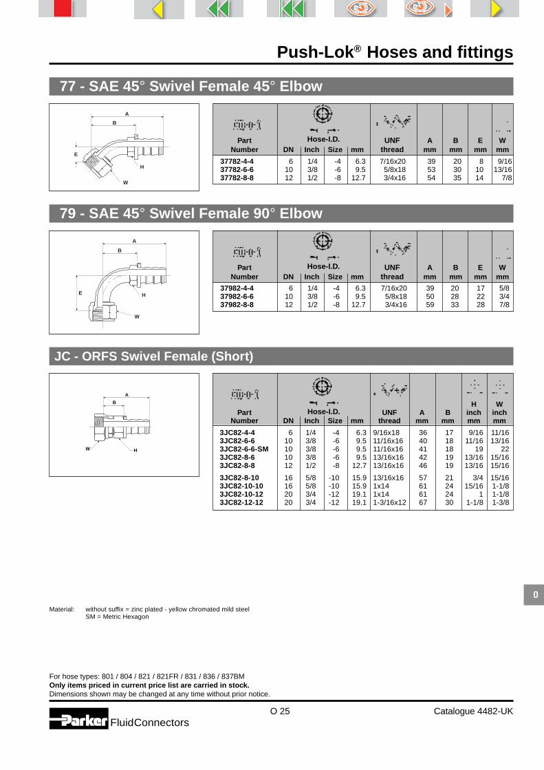
O 25 Catalogue 4482-UKFluidConnectors
O
Push-Lok® Hoses and fittings
For hose types: 801 / 804 / 821 / 821FR / 831 / 836 / 837BMOnly items priced in current price list are carried in stock.Dimensions shown may be changed at any time without prior notice.
77 - SAE 45° Swivel Female 45° Elbow
B
W
H
A
E37782-4-4 6 1/4 -4 6.3 7/16x20 39 20 8 9/1637782-6-6 10 3/8 -6 9.5 5/8x18 53 30 10 13/1637782-8-8 12 1/2 -8 12.7 3/4x16 54 35 14 7/8
79 - SAE 45° Swivel Female 90° Elbow
B
A
E
W
H37982-4-4 6 1/4 -4 6.3 7/16x20 39 20 17 5/837982-6-6 10 3/8 -6 9.5 5/8x18 50 28 22 3/437982-8-8 12 1/2 -8 12.7 3/4x16 59 33 28 7/8
Hose-I.D.Part UNF A B E WNumber DN Inch Size mm thread mm mm mm mm
Hose-I.D.Part UNF A B E WNumber DN Inch Size mm thread mm mm mm mm
JC - ORFS Swivel Female (Short)
A
B
W H
Material: without suffix = zinc plated - yellow chromated mild steelSM = Metric Hexagon
Hose-I.D.
3JC82-4-4 6 1/4 -4 6.3 9/16x18 36 17 9/16 11/163JC82-6-6 10 3/8 -6 9.5 11/16x16 40 18 11/16 13/163JC82-6-6-SM 10 3/8 -6 9.5 11/16x16 41 18 19 223JC82-8-6 10 3/8 -6 9.5 13/16x16 42 19 13/16 15/163JC82-8-8 12 1/2 -8 12.7 13/16x16 46 19 13/16 15/16
3JC82-8-10 16 5/8 -10 15.9 13/16x16 57 21 3/4 15/163JC82-10-10 16 5/8 -10 15.9 1x14 61 24 15/16 1-1/83JC82-10-12 20 3/4 -12 19.1 1x14 61 24 1 1-1/83JC82-12-12 20 3/4 -12 19.1 1-3/16x12 67 30 1-1/8 1-3/8
H WPart UNF A B inch inch
Number DN Inch Size mm thread mm mm mm mm

O 26 Catalogue 4482-UKFluidConnectors
Push-Lok® Hoses and fittings
O
For hose types: 801 / 804 / 821 / 821FR / 831 / 836 / 837BMOnly items priced in current price list are carried in stock.Dimensions shown may be changed at any time without prior notice.
A
B
E H
W
Hose-I.D.
3J182-4-4 6 1/4 -4 6.3 9/16x18 44 25 46 11/163J182-6-6 10 3/8 -6 9.5 11/16x16 54 31 54 13/163J182-8-8 12 1/2 -8 12.7 13/16x16 61 35 64 15/16
Part UNF A B E WNumber DN Inch Size mm thread mm mm mm inch
J1 - ORFS Swivel Female 90° Elbow (Extra Long)
AB
H JM fittings are supplied without O-Ring. For fittings with O-Ring please replace JM by J0.Fittings with standard O-Ring seals can be used for temperatures from -30 °C up to +105 °C.Find O-Rings in section I. Special O-Rings are available on request.
Hose-I.D.
3JM82-8-8 12 1/2 -8 12.7 13/16x16 48 22 9/163JM82-12-12 20 3/4 -12 19.1 1-3/16x12 68 31 1-1/8
Part UNF A B HNumber DN Inch Size mm thread mm mm inch
JM - ORFS Male
J9 - ORFS Swivel Female 90° Elbow
A
B
E H
W
Hose-I.D.
3J982-4-4 6 1/4 -4 6.3 9/16x18 49 30 21 11/163J982-6-6 10 3/8 -6 9.5 11/16x16 52 29 23 13/163J982-8-6 10 3/8 -6 9.5 13/16x16 56 33 32 15/163J982-6-8 12 1/2 -8 12.7 11/16x16 55 29 23 13/163J982-8-8 12 1/2 -8 12.7 13/16x16 60 34 29 15/16
3J982-10-10 16 5/8 -10 15.9 1x14 72 35 32 1-1/83J982-12-12 20 3/4 -12 19.1 1-3/16x12 79 42 48 1-3/8
Part UNF A B E WNumber DN Inch Size mm thread mm mm mm inch
J7 - ORFS Swivel Female 45° Elbow
A
B
E
HW
Hose-I.D.
3J782-4-4 6 1/4 -4 6.3 9/16x18 49 30 10 11/163J782-6-6 10 3/8 -6 9.5 11/16x16 55 33 11 13/163J782-8-6 10 3/8 -6 9.5 13/16x16 65 41 15 15/163J782-8-8 12 1/2 -8 12.7 13/16x16 67 41 15 15/163J782-10-10 16 5/8 -10 15.9 1x14 79 43 16 1-1/8
3J782-12-12 20 3/4 -12 19.1 1-3/16x12 82 45 21 1-3/8
Part UNF A B E WNumber DN Inch Size mm thread mm mm mm inch

O 27 Catalogue 4482-UKFluidConnectors
O
Push-Lok® Hoses and fittings
For hose types: 801 / 804 / 821 / 821FR / 831 / 836 / 837BMOnly items priced in current price list are carried in stock.Dimensions shown may be changed at any time without prior notice.
FB - French Compression Swivel Female
A
B
W
B and BK parts have brass nipples and steel nuts.
Hose-I.D.
3FB82-6-4B 6 1/4 -4 6.3 M10x1 6 35 16 143FB82-8-4B 6 1/4 -4 6.3 M12x1 8 31 12 143FB82-10-4B 6 1/4 -4 6.3 M16x1.5 10 31 12 193FB82-10-6B 10 3/8 -6 9.5 M16x1.5 10 34 12 193FB82-14-6B 10 3/8 -6 9.5 M20x1.5 14 35 12 24
3FB82-14-8B 12 1/2 -8 12.7 M20x1.5 14 38 12 243FB82-18-8B 12 1/2 -8 12.7 M24x1.5 18 40 14 303FB82-18-10B 16 5/8 -10 15.9 M24x1.5 18 50 15 303FB82-22-12B 20 3/4 -12 19.1 M30x1.5 22 53 17 363FB82-28-16B 25 1 -16 25.4 M36x1.5 28 52 15 42
3FB82-28-16BK 25 1 -16 25.4 M36x1.5 28 52 14 42
TubePart Thread O.D. A B W
Number DN Inch Size mm metric mm mm mm mm
FF - Metru-Lok Swivel Female
A
B
W
B and BK parts have brass nipples and steel nuts.
Hose-I.D.
3FF82-6-4B 6 1/4 -4 6.3 M10x1 6 36 16 143FF82-8-4B 6 1/4 -4 6.3 M12x1 8 31 12 143FF82-10-6B 10 3/8 -6 9.5 M14x1 10 35 12 173FF82-12-6B 10 3/8 -6 9.5 M16x1 12 35 12 193FF82-14-8B 12 1/2 -8 12.7 M18x1 14 38 12 22
3FF82-16-8B 12 1/2 -8 12.7 M22x1.5 16 38 12 243FF82-18-10B 16 5/8 -10 15.9 M24x1.5 18 51 15 273FF82-22-12B 20 3/4 -12 19.1 M28x1.5 22 51 15 32
TubePart Thread O.D. A B W
Number DN Inch Size mm metric mm mm mm mm
Material: without suffix = zinc plated - yellow chromated mild steelB = BrassBK = Brass without plastic ring

O 28 Catalogue 4482-UKFluidConnectors
Push-Lok® Hoses and fittings
O
For hose types: 801 / 804 / 821 / 821FR / 831 / 836 / 837BMOnly items priced in current price list are carried in stock.Dimensions shown may be changed at any time without prior notice.
DE - Double Banjo Union
B
D
A
Find banjo bolts on page O29.
Hose-I.D.
3DE82-8-4 6 1/4 -4 6.3 8 37 183DE82-10-4 6 1/4 -4 6.3 10 42 233DE82-12-4 6 1/4 -4 6.3 12 45 243DE82-10-6 10 3/8 -6 9.5 10 46 233DE82-12-6 10 3/8 -6 9.5 12 47 24
3DE82-14-6 10 3/8 -6 9.5 14 49 253DE82-16-6 10 3/8 -6 9.5 16 52 28
DiameterPart D A B
Number DN Inch Size mm mm mm mm
B
D
A
Find banjo bolts on page O29.
Hose-I.D.
34982-8-4 6 1/4 -4 6.3 8 36 1734982-10-4 6 1/4 -4 6.3 10 38 1934982-12-4 6 1/4 -4 6.3 12 40 2134982-14-4 6 1/4 -4 6.3 14 42 2334982-10-6 10 3/8 -6 9.5 10 42 19
34982-12-6 10 3/8 -6 9.5 12 44 2134982-14-6 10 3/8 -6 9.5 14 47 2434982-14-6C 10 3/8 -6 9.5 14 47 2434982-16-6 10 3/8 -6 9.5 16 49 2634982-17-6 10 3/8 -6 9.5 17 49 26
34982-17-6C 10 3/8 -6 9.5 17 49 2634982-14-8 12 1/2 -8 12.7 14 51 2534982-18-8 12 1/2 -8 12.7 18 55 2834982-22-8 12 1/2 -8 12.7 22 58 3134982-22-10 16 5/8 -10 15.9 22 68 32
34982-26-12 20 3/4 -12 19.1 26 73 37
DiameterPart D A B
Number DN Inch Size mm mm mm mm
49 - Banjo Union DIN 7642
Material: without suffix = zinc plated - yellow chromated mild steelC = Stainless Steel

O 29 Catalogue 4482-UKFluidConnectors
O
Push-Lok® Hoses and fittings
For hose types: 801 / 804 / 821 / 821FR / 831 / 836 / 837BMOnly items priced in current price list are carried in stock.Dimensions shown may be changed at any time without prior notice.
AM/AR - Banjo Bolt (DIN 7643)
L
G
H
L1
G
H
AM3 A2M3 8 M8x1 17 26 12AM4 A2M4 10 M10x1 19 30 14AR4 10 1/8 19 14AM6 A2M6 12 M12x1.5 26 38 17AM8 A2M8 14 M14x1.5 26 41 19
AR8 14 1/4 26 19AR-08C 1/4 26 19AM10 A2M10 16 M16x1.5 28 46 22AR10 17 3/8 29 22AM13 18 M18x1.5 32 24
AM16 22 M22x1.5 40 27AR16 22 1/2 40 27AM20 26 M26x1.5 45 32
I.D. G L L1Part Number Part Number Banjo Thread. Single Double H
single double mm metric / inch mm mm mm
82 - Push-Lok® Union
A
Hose-I.D.
38282-4-4B 6 1/4 -4 6.3 4538282-6-6B 10 3/8 -6 9.5 5438282-8-8 12 1/2 -8 12.7 6438282-10-10 16 5/8 -10 15.9 8438282-10-10B 16 5/8 -10 15.9 84
38282-12-12 20 3/4 -12 19.0 8438282-12-12B 20 3/4 -12 19.1 84
Part ANumber DN Inch Size mm mm
Standard material: brass
VW - Push-in Connector (VW standard 39-V-16619)
A
B
D
Standard material: brass
Hose-I.D.
3VW82-6-4BK 6 1/4 -4 6.3 6 42 23 53VW82-8-4BK 6 1/4 -4 6.3 8 44 24 53VW82-8-4CK 6 1/4 -4 6.3 8 44 24 53VW82-10-6BK 10 3/8 -6 9.5 10 49 26 83VW82-14-8BK 12 1/2 -8 12.7 14 56 29 11
TubePart O.D. A B D
Number DN Inch Size mm MM mm mm mm
Material: without suffix = zinc plated - yellow chromated mild steelB = BrassBK = Brass without plastic ringC = Stainless steelK = Without plastic ring

O 30 Catalogue 4482-UKFluidConnectors
Push-Lok® Hoses and fittings
O
For hose types: 801 / 804 / 821 / 821FR / 831 / 836 / 837BMOnly items priced in current price list are carried in stock.Dimensions shown may be changed at any time without prior notice.
VW121 - BSP Swivel Female (VW standard 39-V-16631)
B
W
D
A
*stainless steel nipple, steel nut**brass nipple, steel nut
Hose-I.D.
VW121-8937* 6 1/4 -4 6.3 1/4x19 32 13 5 17VW121-8938** 10 3/8 -6 9.5 3/8x19 38 15 7,5 19VW121-8939** 14 1/2 -8 12.7 1/2x14 46 19 11 27VW121-8940** 16 5/8 -10 15.9 3/4x14 58 21 14 32VW121-8941** 20 3/4 -12 19.0 1x11 53 16 17 41
Part BSP A B D WNumber DN Inch Size mm thread mm mm mm mm
VW39D - Push-in Connector (VW standard 39D-1401)
Material: without suffix = zinc plated - yellow chromated mild steelB = BrassC = Stainless Steel
Hose-I.D.
VW39D-1401/1C -1 4 46 5VW39D-1401/2B 3 1/8 -2 3.2 6 55 8VW39D-1401/3B 5 3/16 -3 4.8 8 64 11VW39D-1401/4B 6 1/4 -4 6.3 10 84 1438282-12-12B 20 3/4 -12 19.1 12 84 18
TubePart O.D. A D
Number DN Inch Size mm mm mm mm
H898202 - Male (Ford standard UWR 003-03180)
B
A
W
Standard material: brass
Hose-I.D.
H898202 10 3/8 -6 9.5 M14x1.5 43 21 17
Part Thread A B WNumber DN Inch Size mm metric mm mm mm
BA
WStandard material: brass
Hose-I.D.
H897995 10 3/8 -6 9,5 M14x1.5 43 21 17
Part Thread A B WNumber DN Inch Size mm metric mm mm mm
H897995 - Female (Ford standard UWR 003-03180)

O 31 Catalogue 4482-UKFluidConnectors
O
Push-Lok® Hoses and fittings
For hose types: 801 / 804 / 821 / 821FR / 831 / 836 / 837BMOnly items priced in current price list are carried in stock.Dimensions shown may be changed at any time without prior notice.
AF - Male BSP Parallel Pipe - Rigid - Straight (with O-ring Seal)
Material: without suffix = zinc plated - yellow chromated mild steelB = Brass
Hose-I.D.
3AF82-2-4B 6 1/4 -4 6.3 1/8x28 34 15 173AF82-4-4B 6 1/4 -4 6.3 1/4x19 39 20 193AF82-4-6B 10 3/8 -6 9.5 1/4x19 43 20 193AF82-6-6B 10 3/8 -6 9.5 3/8x19 46 23 223AF82-6-8B 12 1/2 -8 12.7 3/8x19 49 22 22
3AF82-8-8B 12 1/2 -8 12.7 1/2x14 53 26 273AF82-8-10B 16 5/8 -10 15.9 1/2x14 63 26 27
Part BSP A B HNumber DN Inch Size mm thread mm mm inch
M14-4C3MX8BH22 - Male nipple 90° elbow (Ford standard UWR 003-04090)
M14-4C3MX8BH22 R 1/4 M14x1.5 14 25 22 12
BPart A thread C M N P
Number inch metric mm mm mm mm
M14-4V3MX8BH17 - Male nipple 45° elbow (Ford standard UWR 003-04045)
M14-4V3MX8BH17 R1/4 M14x1.5 14 18 17 12
BPart A thread C M N P
Number inch metric mm mm mm mm
M14-4F3MX8BL31 - Male nipple straight fitting (Ford standard UWR 003-04180)
M14-4F3MX8BL31 R 1/4 M14x1.5 17 31 12
BPart A thread C L P
Number inch metric mm mm mm

O 32 Catalogue 4482-UKFluidConnectors
Push-Lok® Hoses and fittings
O
For hose types: 801 / 804 / 821 / 821FR / 831 / 836 / 837BMOnly items priced in current price list are carried in stock.Dimensions shown may be changed at any time without prior notice.
M14-4C63MX8BH22 - Male swivel nut 90° elbow (Ford standard UWR 003-03090)
M14-4C63MX8BH22 R 1/4 M14x1.5 14 17 24 22 11 12
BPart A thread C C1 M N O P
Number inch metric mm mm mm mm mm mm
M14-4F63MX8BL32 - Male swivel nut straight fitting (Ford standard UWR 003-03180)
M14-4F63MX8BL32 R 1/4 M14x1.5 17 17 32 11 12
BPart A thread C C1 L O P
Number inch metric mm mm mm mm mm
M14-4V63MX8BH17 - Male swivel nut 45° elbow (Ford standard UWR 003-03045)
M14-4V63MX8BH17 R 1/4 M14x1.5 14 17 20 17 11 12
BPart A thread C C1 M N O P
Number inch metric mm mm mm mm mm mm

O 33 Catalogue 4482-UKFluidConnectors
O
Push-Lok® Hoses and fittings
Medium I II III IV V STEEL BRASS SS
Acetic Acid X X X A (7) X X AAcetone X X X A A A A AAcetylene X X X X (2) - - -Addinol okoplus HETG 32-68 A(4) F(14) - - - A A AAddinol okosynth HEES 46 F(4) F(14) - - - A A AAEROSHELL Turbine Oil 500 F(3) F X A X A A AAgip Arnica S46 A(3) F(14) - - - A A AAir (1,4) A A A A A A A AAir (dry) (13) F F X A A A A AAlcohol (Methanol-Ethanol) F F F F F F A AAmmonium Chloride A A A A A X X XAmmonium Hydroxide F F F A A F X AAmmonium Nitrate A A A F A F X AAmmonium Phosphate A A A A A X X FAmmonium Sulfate A A A A A F X FAmyl Alcohol X X X F F X A AAnhydrous Ammonia X X X X X X X XAniline X X X F A A X AAnimal Fats F(3) F X F F (7) (7) AAral Vitam EHF 46 A(4) A(14) - - - A A AAromatic 100,150 F(3) F X - X A A AAsphalt X F X F X X (7) AASTM #3 Oil F F F F X A A AATF-M (3) A F A X A A AAutomotive Brake Fluid X X X X - X X XAvia Aviacub synthofluid F(4) A(14) - - - A A AAvia hydraulik bio A(4) F(14) - - - A A ABenzene, Benzol X X X F X A A ABenzine X X X F X A A ABorax F(3) F F F A F A ABoric Acid A A A X A X (7) ABP biohyd SE 46 (3) F(14) - - - A A ABP energol HLP-HM 68 A A A F X A A ABrayco 882 (3) A X A X A A ABrayco Micronic 776RP (3) A F F X A A ABrayco Micronic 889 F(3) F X - X A A ABrine F F F A A X F (7)Butane F(2) F X - X A A AButyl Alcohol, Butanol F F F F F F F ACalcium Chloride A A A F A F F XCalcium Hydroxide A A A A A A A ACalcium Hypochlorite X X X A A X (7) XCalibrating Fluid A A A A X A A ACarbon Dioxide F(7) F F F (7) A A ACarbon Disulfide X X X F X A F ACarbon Monoxide (hot) F F F F (7) F (7) ACarbon Tetrachloride X X X F X (7) (7) (7)Carbonic Acid F F F X F X X FCastor Oil A A A A A A A ACastrol 5000 F(3) F X A X A A ACastrol BioTec Alpin 22 (3) A(4) - - - A A ACelluguard A A A - A A A AChevron Clarity AW 32, 46, 68 A A A A X A A AChevron FLO-COOL 180 F F F - X A A AChevron FR-8, 10, 13, 20 X X X X A A A AChevron Hydraulic Oils AW MV 15, 32, 46, 68, 100 A A A A X A A AChevron HyJet IV (9) X X X X A A A ACitric Acid (3) A F X A X (7) (7)Coolanol 15, 20, 25, 35, 45 A A A A A A A ACopper Chloride (3) A F X A X (7) XCopper Sulfate A A A X A X X (7)Cosmolubric HF-122, HF-130, HF-144 (11) (11) X X X A A ACottonseed Oil (3) A F F X A A ACrude Petroleum Oil (3) A F A X (7) (7) ADEA econa E46 A(4) F(14) - - - A A ADeionized Water A A A A A F F ADextron II ATF (3) A F A X A A ADiesel Fuel (3) A X A X A A ADiester Fluids X X X F X A A ADow Corning DC 200, 510, 550, 560, FC126 A A A F - A A ADow HD50-4 F F F - - - - ADowtherm A,E X X X F X A A ADowtherm G X X X X X A A AElf hydrelf bio 46 A(4) A(14) - - - A A AEsso hydrauliköl HE 46 A(4) F(14) - - - A A AEthanol F F F F F F A AEthers - - - F - A A AEthyl Acetate X X X F F F A AEthyl Alcohol F F F F F F A AEthyl Cellulose F F F F F X F FEthyl Chloride X X X X A F F FEthylene Dichloride X X X F X X A XEthylene Glycol (3) A F A A A F AExxon 3110 FR A A A A X A A A
Push-Lok Chemical Resistance

O 34 Catalogue 4482-UKFluidConnectors
Push-Lok® Hoses and fittings
O
Exxon Esstic A A A A A A A AExxon Nuto H 46, 68 A A A A X A A AExxon Tellura Indusrial Process Oils A A A A X A A AExxon Terresstic A A A A A A A AExxon Turbo Oil 2380 (3) A X F X A A AExxon Univolt 60, N61 (3) A F A X A A AFinke aviaticon HY-HE 46 A(3) A(14) - - - A A AFormaldehyde X X X A A X F AFormic Acid X X X X A X (7) XFragol Hydraulic TR 46 A(4) F(14) - - - A A AFragol Hydraulik HE 46 (3) F(14) - - - A A AFreons see refrigerants - - - - - - - -Fuchs Plantosyn 3268 ECO F(4) F(14) - - - A A AFuchs Plantosyn 3268 (3) A(4) - - - A A AFuel Oil (3) A F A X A A AFyre-Safe 120C,126,155,1090E,1150,1220,1300E X X X X A A A AFyre-Safe 200C, 225, 211 (3) A F A A A A AFyre-Safe W/O A A A A X A A AFyrguard 150, 150-M, 200 A A A A A A A AFyrquel 60, 90, 150, 220, 300, 550, 1000 X X X X A A A AFyrquel EHC, GT, LT, VPF X X X X A A A AFyrtek MF, 215, 290, 295 X X X X X A A AGasoline (2,12) X X X X X A A AGlue. F F F - X A F AGlycerine, Glycerol A A A A A A F AGrease A A A A X A A AGulf-FR Fluid P37, P40, P43, P45, P48 X X X F A A A AH-515 (NATO) A A A - X A A AHalon 1211, 1301 F F F F - A A AHelium Gas X X X X X A A AHeptane F(3) F X A X A A AHexane F(3) F X A X A A AHoughto-Safe 1055, 1110, 1115, 1120, 1130 (9) X X X X A A A AHoughto-Safe 271 to 640 (3) A F F A A A AHoughto-Safe 419R Deicer Fluid (3) A A - - A A AHoughto-Safe 5046, 5046W, 5047-F A A A A X A A AHP 100C (Jack hammer oil) (3) A F A X A A AHydrochloric Acid X X X X X X (7) XHydrofluoric Acid X X X X X X (7) XHydrogen Gas (2,15) X X X X X A A AHydrogen Peroxide X X X F X X X (7)Hydrogen Sulfide X X X X A X X (7)Hydrolube A A A F A A A AHydrolubric 120-B, 141, 595 (3) A F F A A A AHydrosafe Glycol 200 A A A A A A F AHyJet IV (9) X X X X A A A AIsocyanates F(3) F F F X A - AIsooctane F(3) F X A X A A AIsopar H X X X X X A A AIsopropyl Alcohol F F F F F F A AJP3 and JP4 (3) A X - X A A AKaeser 150P, 175P, 325R, 687R X X X F X A A AKerosene (2, 3, 15) (3) A X F X A A ALacquer X X X F X X A ALacquer Solvents X X X F X X A ALactic Acids X X X X X X (7) ALindol HF X X X F A A A ALinseed Oil A A A A A A A ALP-Gas (2) (2) (2) X X X A A AMagnesium Chloride A A A A A X (7) XMagnesium Hydroxide F F F A A F F FMagnesium Sulfate A A A A A A F AMercaptans X X X X X - - -Methane (2,3) A F F X A A AMethanol F F F F F F A AMethyl Alcohol F F F F F F A AMethyl Chloride X X X F X A A AMethyl Ethyl Ketone (MEK) X X X F X F A AMethyl Isopropyl-Ketone (15) X X X X X F A AMIL-B-46176A X X X X X X X XMIL-H-46170 F(3) F X F X A A AMIL-H-5606 (3) A F A X A A AMIL-H-6083 (3) A F A X A A AMIL-H-7083 (3) A F A X A A AMIL-H-83282 (3) A F A X A A AMIL-L-2104, 2104B (3) A F A X A A AMIL-L-23699 F(3) F X A X A A AMIL-L-7808 (3,6) A F - X A A AMine Guard FR A A A - A A A AMineral Oil A A A F X A A AMineral Spirits (10) (10) (10) (10) X A A AMobil Aero HFE (3) A F F X A A AMobil DTE 11M, 13M, 15M, 16M, 18M, 19M (3) A F A X A A AMobil DTE 22, 24, 25, 26 (3) A F A X A A AMobil EAL 224H (3) A X X - A A AMobil EAL Syndraulik 46 F(4) A(14) - - - A A AMobil Glygoyle 11, 22, 30, 80 A A A - X A A A
Medium I II III IV V STEEL BRASS SS

O 35 Catalogue 4482-UKFluidConnectors
O
Push-Lok® Hoses and fittings
Medium I II III IV V STEEL BRASS SS
Mobil HFA (3) A F A X A A AMobil Jet 2 F(3) X X A X A A AMobil Nyvac 20, 30, 200, FR (3) A F F A A A AMobil Rarus 824, 826, 827 X X X F X A A AMobil SHC 600 Series (3) A F A X A A AMobil SHC 800 Series (3) A F A X A A AMobil SHL 624 (3) A - A X A A AMobil Vactra Oil A A A F X A A AMobil XRL 1618B X X X X A A A AMobilfluid 423 (3) A F A X A A AMobilgear SHC 150, 220, 320, 460, 680 F(3) X F F X A A AMobilrama 525 A A A F X A A AMolub-Alloy 890 X X X F X A A AMoly Lube „HF“ 902 F(3) F F F X A A AMonolec 6120 Hydraulic Oil A A A A X A A AMorpholine (pure additive) X X X X X X X ANaptha F(3) F X A X A A ANapthalene X X X F X A A ANatural Gas (2) (2) (2) X X X A A ANitric Acid X X X X X X X (7)Nitrobenzene X X X F X X X (7)Nitrogen F(1) F(1) F(1) F(1) F(1) A A ANuto H 46, 68 A A A A X A A ANyvac 20, 30, 200, FR (3) A F F A A A ANyvac Light X X X - A A A AOil Synthetic Blends X X X X X A A AOxygen (2,15) X X X X X X A AOzone F F F - A A A APanolin HLP synth 46 (3) A(4) - - - A A APerchloroethylene X X X X X F X APetroleum Ether F(3) F X F X A A APetroleum Oils A A A A X A A APhenol (Carbolic Acid) X X X A X X F APhosphate Ester Blends X X X X X A A APhosphate Esters (9) X X X X A A A APhosphoric Acid X X X X X X X (7)Polyalkylene Glycol F F A - X A A APolyol Ester (11) F X X X A A APotassium Chloride A A A A A X F (7)Potassium Hydroxide X X X F A (7) X APotassium Sulfate A A A A A A A APropane (2) (2) X X X A A APropylene Glycol (3) A F A A F F FPydraul 60, 150, 625, F9 (9) X X X X A A A APydraul 90, 135, 230, 312, 540, MC (9) X X X X F A A APydraul A-200 X X X F X A A APyro Gard 43, 230, 630 (9) X X X F X A A APyro Gard C, D, R, 40S, 40W (3) A F F A A A APyro Guard 53, 55, 51, 42 (9) X X X X A A A AQuintolubric 700 A A A A A A F AQuintolubric 822, 833 (11) (11) X X X A A AQuintolubric 957, 958 (3) A F F A A A ARefrigerant Freon 113, 114 (5) X X X X X A A ARefrigerant Freon 12 (5) X X X X X A A ARefrigerant Freon 22 (5) X X X X X A A ARefrigerant Freon 502 (5) X X X X X A A ARefrigerant HFC134A (5) X X X X X A A ARTV Silicone Adhesive Sealants (15) X X X X X A A ASafco-Safe T10, T20 A - - - A F F ASafety-Kleen ISO 32, 46, 68 hydraulic oil (3) A F - X A A ASafety-Kleen Solvent (10) (10) (10) (10) X A A ASantoflex 13 F F F - F A A ASantosafe 300 X X X - X A A ASantosafe W/G 15 to 30 A - - A A A A ASea Water F F F F A X F (7)Sewage F(3) F F A F (7) (7) (7)Shell 140 Solvent (10) (10) (10) (10) X A A AShell Clavus HFC 68 X X X X X A A AShell Comptella Oil F(3) F F A X A A AShell Comptella Oil S 46, 68 F(3) F F A X A A AShell Comptella Oil SM F(3) F F A X A A AShell Diala A, (R) Oil AX (3) A F F X A A AShell FRM A - - - X A A AShell IRUS 902, 905 A A A - A A A AShell naturelle HFE 46 F(4) A(14) - - - A A AShell Pella-A A A A A X A A AShell Tellus (3) A F A X A A AShell Thermia Oil C A A A A X A A AShell Turbo R F(3) F X A X A A ASHF 220, 300, 450 (11) (11) X X X A A ASilicate Esters A F A A X A A ASilicone Oils A A A - - A A ASkydrol 500B-4, LD-4 X X X X A(8) A A ASoap Solutions F(3) F X F A A A ASoda Ash, Sodium Carbonate A A A A A A F ASodium Bisulfate F F F A A F A FSodium Chloride F F F A A X F A

O 36 Catalogue 4482-UKFluidConnectors
Push-Lok® Hoses and fittings
O
Medium I II III IV V STEEL BRASS SS
Hose selection by medium and hose typeThis hose compatibility chart is a ready reference of Parker hose adaptability with various media. It is intended as a guide to chemical compatibility withthe internal fluid and assembly lubricant applied internally. While all listings shown reflect known usage or authoritative sources, other factors may insome cases render them invalid. Final hose selection depends also upon pressure, fluid temperature, ambient temperature, and special requirementsor variations which may not be known by Parker Hannifin. Legal and other regulations applicable to footnotes (2), (3) and (4) must be followed withparticular care. Where an external compatibility problem may occur or for fluids not listed, contact your Parker Hannifin field representative.
Resistant rating key: A = Prefered F = Fair X = Unsuitable – = No recommendation
Column I
801, 821, 821FR, 837BM,
Column II
831
Column III
77C, 78C
Column IV
206, 213, 266, 296, 636, 836
Column V
804
(1) Hose must be pin pricked(2) Legal and insurance regulations must be considered(3) hoses in column 2 are recommended(4) Maximum 158 °F (70 °C)(5) hose 235 and 285 are recommended for refrigerants(6) Maximum 185 °F (85 °C)(7) Satisfactory at some concentrations and temperatures,
unsatisfactory at others(8) Some discoloration of fluid may occur without damage to
fluid properties(9) For phosphate ester fluids use Column V, 235, 285 hoses
(10) Acceptable for flushing hose assemblies(11) Use 381, 481, 772, or 831(12) 221FR hose recommended(13) For dry air applications hoses from column 2, 4, 5 and 235 is
recommended.(14) Maximum 212 °F (100 °C)(15) hoses 235 and 285 are recommended
Sodium Hydroxide X X X A A A X ASodium Hypochlorite F F F X F X X XSodium Nitrate F F F A A A (7) ASodium Peroxide X X X X A X X ASodium Silicate A A A A A A A ASodium Sulfate A A A A A A A ASoybean Oil (3) A F A A A A ASteam X X X X X F A AStoddard Solvent (10) (10) (10) (10) X A A ASulfur Chloride X X X F X (7) X (7)Sulfur Dioxide X X X X F X (7) FSulfur Trioxide X X X F F X X XSulfuric Acid F(7) F F X F(7) (7) X (7)Tannic Acid (3) A F F A X (7) XTar X F F F X X (7) ATebiol Esterhyd HE 46 F(4) F(14) - - - A A ATellus (Shell) (3) A F A X A A ATexaco 760 Hydrafluid A - - - X A A ATexaco 766, 763 (200 - 300) A - - - A F F ATexaco A-Z Oil A A A F X A A ATexaco Way Lubricant 68 A A A A X A A AToluene, Toluol X X X F X A A ATransmission Oil A A A A X A A ATribol 1440 F(3) F X X X A A ATrichloroethylene X X X F X X A ATrim-Sol (3) A F F X A A ATurpentine X X X F X A A AUcon Hydrolubes (3) A F F A A A AUnivis J26 A A - A X A A AUnleaded Gasoline (2,12) X X X X X A A AUrea F F F A F F - FUrethane Formulations A A A A - A A AVarnish X X X F X F F AVarsol F(3) F (10) (10) X A A AVersilube F44, F55 A A - A - A A AVinegar X X X F A (7) X AVolt Esso 35 A A A A X A A AWater A A F A A F A AWater / Glycols (3) A A A A A F AXylene, Xylol (15) X X X X X A A AZerol 150 A A A A X A A AZinc Chloride A A A X A X X FZinc Sulfate A A A X) A X A A

Thermoplastic single tubesand Pneumo-Tube bundles
Catalogue 5210-UK

Thermoplastic single tubes and Pneumo-Tube bundles
P 2 Catalogue 5210-UKFluidConnectors
P
Index Pages
Thermoplastic single tubes and Pneumo-Tube bundles P 3
Polyamide tubing P 4-P 5
Polyurethane tubing P 6-P 7
Ordering information P 8
Technical tube preparation P 8
Tube bundles P 9-P10
Singleline Pneumotube P 11

Thermoplastic single tubes and Pneumo-Tube bundles
P 3 Catalogue 5210-UKFluidConnectors
P
Applications
Pneumatics
Lubrication systems
Process control lines
Instrumentation and control
Robotics systems
Pressurised air tools
Paint systems
Automation systems
Medical applications
Food and beverage applications
Fluid applications
Principle
All Parker tubes are manufactured to internationalstandards and are fully compatible with Parker’s widerange of push-in, compression and screw type tubefittings, for example Parflex thermoplastic fittings such asFast & Tite®, TrueSealTM, Par-Barb and Mini-Barb as wellas components from the Parker Pneumatic ConnectorsHandbook.
Standard packaging of all Parker single tube products ispolyethylene bags.Dispensing cardboard boxes (K) are available on request.

Thermoplastic single tubes and Pneumo-Tube bundles
P 4 Catalogue 5210-UKFluidConnectors
P
Working pressure of polyamide tubing is dependant on the operating temperature.Working pressures shown are based on a design factor of 3:1
Parker calibrated polyamide tubing
Parker calibrated polyamide tubing is extruded in polyamide (PA11/12) for use with pneumatic fittings.This is manufactured within the limits of DIN 73378, BS 5409 PT1 and CETOP RP54 P recommendations, and isideal for pneumatic applications.For continuous use at high temperature we recommend tube which is protected against heat and light.
Advantages
- Good vibration/damping properties, - High abrasion resistance- Tubing available in several colours for easy - Low pressure drop, identification - No thermal expansion
Technical features
Tube size°C
Working pressure (bar)
- 40 - 20 0 20 30 40 50 60
N3 x 0.60 33 33 33 33 25 25 19 19N4 x 0.65 26 26 26 26 19 19 15 15N4 x 1 44 44 44 44 33 33 25 25N5 x 1 33 33 33 33 25 25 19 19N6 x 1 27 27 27 27 20 20 15 15N8 x 1 19 19 19 19 14 14 11 11
N10 x 1 15 15 15 15 11 11 8 8N10 x 1.25 19 19 19 19 14 14 11 11N10 x 1.5 24 24 24 24 17 17 13 13N12 x 1 12 12 12 12 9 9 7 7N14 x 1.5 16 16 16 16 12 12 9 9N16 x 1.5 14 14 14 14 10 10 8 8

Thermoplastic single tubes and Pneumo-Tube bundles
P 5 Catalogue 5210-UKFluidConnectors
P
Parker calibrated polyamide tubing
Tube bend radiusTo ensure the correct functioning of both tubefitting and pneumatic system it is important not toexceed the minimum bend radius of the tube.
Chemical compatibilityParker polyamide tubing is suitable for use with a wide variety of fluids. The table below shows typical fluids usedwith polyamide tubing.
A = excellent, B = medium, C = poorFor other fluids please contact us
Colours and sizes availableFor identification purposes Parker can supply on request, tubes in several colours : red, blue, green, yellow and black.Parker tubing is packaged and delivered as standard in 100 metre lengths for sizes 3 x 0.65 to 12 x 1 and in 25 metrelengths for larger sizes.
Tube ToleranceOD mm
3 to 5 mm + 0.05- 0.08
6 to 16 mm + 0.05- 0.10
Tube outside diametertolerances
Tube Minimumsize bend radius (mm)
3 x 0.60 154 x 0.65 204 x 1 205 x 1 356 x 1 358 x 1 45
10 x 1.25 6010 x 1 6012 x 1 7014 x 1.50 8516 x 1.50 95
FluidWorking temperature
-20°C +20 °C +60 °CCutting oil A A ACutting fluids A A AWater A A AHydraulic oils A A AMineral oils / greases A A ACarbon dioxide A A AAcetone A A AGasoline B B BTrichloroethylene - C C
Tube size (mm) Tube Part numberLength
OD ID Wall Thickness (m) Natural (1) Red (2) Blue (3) Green (4) Black (5) Yellow (7)
3 1.7 0.60 100 N3x0.65/1-100 N3x0.65/2-100 N3x0.65/3-100 N3x0.65/4-100 N3x0.65/5-100 N3x0.65/7-1004 2.7 0.65 100 N4x0.65/1-100 N4x0.65/2-100 N4x0.65/3-100 N4x0.65/4-100 N4x0.65/5-100 N4x0.65/7-100
4 2 1 100 N4x1/1-100 N4x1/2-100 N4x1/3-100 N4x1/4-100 N4x1/5-100 N4x1/7-1005 3 1 100 N5x1/1-100
6 4 1 100 N6x1/1-100 N6x1/2-100 N6x1/3-100 N6x1/4-100 N6x1/5-100 N6x1/7-1008 6 1 100 N8x1/1-100 N8x1/2-100 N8x1/3-100 N8x1/4-100 N8x1/5-100 N8x1/7-100
10 7.5 1.25 100 N10x1.25/1-100 N10x1.25/2-100 N10x1.25/3-100 N10x1.25/4-100 N10x1.25/5-100 N10x1.25/7-10010 8 1 100 N10x1/1-100 N10x1/2-100 N10x1/3-100 N10x1/4-100 N10x1/5-100 N10x1/7-10012 10 1 100 N12x1/1-100 N12x1/2-100 N12x1/3-100 N12x1/4-100 N12x1/5-100 N12x1/7-10014 11 1.50 25 N14x1.5/1-25 N14x1.5/2-25 N14x1.5/3-25 N14x1.5/4-25 N14x1.5/5-25 N14x1.5/7-2516 13 1.50 25 N16x1.5/1-25 N16x1.5/2-25 N16x1.5/3-25 N16x1.5/4-25 N16x1.5/5-25 N16x1.5/7-25

Thermoplastic single tubes and Pneumo-Tube bundles
P 6 Catalogue 5210-UKFluidConnectors
P
Working pressure of polyurethane tubing is dependant on the operating temperature.Working pressures shown are based on a design factor of 3:1
Parker calibrated polyurethane tubing is obtained by extrusion. The material hardness is 52 Shore D.Its very high flexibility allows a small minimum bend radius for compact installations.A dimensional inspection system based on advanced laser technology maintains a tight tolerance on the outsidetube diameter.This is manufactured within the limits of NF E49 - 101 1994 recommendations.
Advantages
- Extreme flexibility with bend radii up to three times - Good vibration resistance,better than polyamide tubing allows compact installations - Light weight,
- Tube available in several colours for line identification, - Reduced fitting time.
Technical features
Parker calibrated polyurethane tubing
Working pressure (bar)
- 35 - 20 0 20 30 40 50 60
TPU 3 x 0.5 12 12 12 12 9 9 8 8TPU 4 x 0.75 14 14 14 14 11 11 9 9TPU 6 x 1 12 12 12 12 9 9 8 8TPU 8 x 1.25 11 11 11 11 9 9 7 7
TPU 10 x 1.5 10 10 10 10 8 8 7 7TPU 12 x 2 12 12 12 12 9 9 8 8TPU 16 x 2.5 11 11 11 11 9 9 7 7
Tube size
°C

Thermoplastic single tubes and Pneumo-Tube bundles
P 7 Catalogue 5210-UKFluidConnectors
P
Parker calibrated polyurethane tubing
Polyurethane tubing outsidediameter tolerances
Tube bend radiusTo ensure the correct functioning of both tubefitting and pneumatic system it is important not toexceed the minimum bend radius of the tube.
Chemical compatibilityParker polyurethane tubing is suitable for use with a wide variety of fluids. The table below shows typical fluids usedwith polyurethane tubing.
A = excellent, B = medium, C = poorFor other fluids please contact us
Colours and sizes availableFor identification purposes Parker polyurethane tubing is available in three colours : blue, black and silver. Parkercalibrated polyurethane tubing is packaged and delivered in 100 meter lengths as standard.
Also available as twin line tubes in black/blue or silver/silver.Deviating constructions also possible.For other tube sizes, colours and lengths please contact us.
Tube ToleranceOD mm
3 to 8 mm ± 0.1
10 and 12 mm ± 0.15
FluidWorking temperature
-20°C +20 °C +60 °CCutting oil A A ACutting fluids A A AWater A A AHydraulic oils A A AMineral oils / greases A A ACarbon dioxide A A AGasoline B B BTrichloroethylene - C CAcetone - C C
Tube size (mm) Tube Part numberLength
OD ID Wall Thickness (m) Blue (3) Black (5) Silver (13)
3 2 0.5 100 TPU3x0.5/3-100 TPU3x0.5/5-100 TPU3x0.5/13-100
4 2.5 0.75 100 TPU4x0.75/3-100 TPU4x0.75/5-100 TPU4x0.75/13-1005 3 1 100 TPU5x1/3-100 TPU5x1/5-100 TPU5x1/13-100
6 4 1 100 TPU6x1/3-100 TPU6x1/5-100 TPU6x1/13-100
8 5.5 1.25 100 TPU8x1.25/3-100 TPU8x1.25/5-100 TPU8x1.25/13-100
10 7 1.5 100 TPU10x1.5/3-100 TPU10x1.5/5-100 TPU10x1.5/13-100
12 8 2 100 TPU12x2/3-100 TPU12x2/5-100 TPU12x2/13-100
Tube Minimumsize bend radius (mm)
3 x 0.5 134 x 0.75 175 x 1 226 x 1 278 x 1.25 37
10 x 1.50 5412 x 2 62

Thermoplastic single tubes and Pneumo-Tube bundles
P 8 Catalogue 5210-UKFluidConnectors
P
Ordering information
Ordering key
Natural1
Red2
Blue3
Green4
Black5
Brown6
Yellow7
Orange8
Grey9
Purple10
Pink11
White12
Colour codes:
Technical tube preparation
Always ensure that the tube is out square beforeassembling it to the fitting.
Silver13
Examples: N 6X1/5-50 K
Cardboard packaging
Length in mColour: black
Wall thickness in mm
Outer diameter in mmPolyamide
2X022L/1-100
Length in mColour: natural
Polyethylene
Wall thickness in inchesOuter diameter in inches
Always use a Parker tube cutter to cut technicaltubing

Thermoplastic single tubes and Pneumo-Tube bundles
P 9 Catalogue 5210-UKFluidConnectors
P
Tube bundles - For maximum safety and minimum installation work
Standard configurations are available in long continuous lengths
Stranded inner tubes formaximum flexibility
PVC coat for protectionagainst damage
Colour-coded inner tubesfor easier identification
Polyester ribbon to ensurea smooth outer cover
Parker Pneumo-Tube bundles are a high-quality thermoplastic product designed especially for process control andmonitoring applications.
Parker Pneumo-Tube bundles are excellent for use in hydraulic and pneumatic systems.
The PVC coat protects the product against mechanical and chemical damage.
Each tube can be easily and quickly identified by its colour and position within the stranded bundle. The singletubes are marked in intervals of max. 500 mm as a standard.
Using a combination of colours, tube and sheath materials, together with various barrier types, Pneumo-Tube canbe constructed to meet the most varied and demanding applications.Electrical wires and tension members can also be incorporated.
1 3 5 7 12 19

Thermoplastic single tubes and Pneumo-Tube bundles
P 10 Catalogue 5210-UKFluidConnectors
P
Tube bundles types
STSType
ETSType
STAType
STBType
AHType
Tube bundle PVC standard thickness sheathed for protection against damage
Tube bundle with extra thick PVC, sheathed for direct underground burial with sand cushion.
Tube bundle, PVC sheathed, with two-layered hoop-steel armouring for direct underground burialwithout special bedding.
Tube bundle PVC sheathed, with thermal barrier for short-term resistance to fire.
Tube bundle, PVC sheathed with double thermal barrier for extra fire protection.
Tube bundle, PVC sheathed with central air supply line.
DTBType

Thermoplastic single tubes and Pneumo-Tube bundles
P 11 Catalogue 5210-UKFluidConnectors
P
Prestoweld 2 tubing
Prestoweld 2 thermoplastic tubing has been specificallydesigned to meet the stringent requirements of the roboticwelding industry for pneumatic control.
The combination of the Prestoweld 2 tubing and instantfittings ensures a cost and time saving during the assembly.
By using weld spark resistant material, Prestoweld 2guarantees a high quality, reliable and long lastingsolution for the air and water supply of welding robots.
Prestoweld 2 single tube is tested and approved by themajor players in the automotive industry.
Technical features
Advantages
D D1 Part number Max. working pressure Max. burst pressure Min. bend radius Weight(mm) (mm) at 23°C (bar) (bar) (mm) (g./m)
2 4 PWPU 4x1 28 84 8 12.04 6 PWPU 6x1 16 50 15 20.05 8 PWPU 8x1.5 19 58 16 38.94 8 PWPU 8x2 28 84 16 47.96 10 PWPU 10x2 21 63 21 63.9
8 12 PWPU 12x2 16 50 30 78.810 14 PWPU 14x2 16 42 47 95.8
Weld sparks resistantmaterials- No protective cover required.- No need for tube prepa- ration.- No additional assembly tool required.- Simple, fast and reliable assembly.- Long service life.
Silicon and labs freetubing- Free of all paint effective substances.- Does not interfere with the coating quality (imperative in the automobile industry).
Colour coding possible- Identification of circuits.- Prevents mix-up of tube functions.
Small bend redius andsmall overall dimensions- Flexibility.- Easy assembly even with limited space.
Material: Weld spark resistant Polyurethane, halogen-free.
Tubing colour: Black.
Branding colour: White (other colours on request).
Working temperature: - 30°C up to + 90°C.
Fittings: Prestoweld 2 instant fittings (see section E).
DD1

Accessories
Catalogue 0026-UK

Accessories
Q 2 Catalogue 0026-UKFluidConnectors
Q
Accessories
2000 - Manual copper tube bender Q 3
2005 - Copper tube cutter Q 3
Par-Lok - Snap-action ratchet spanner Q 3
PTC - Plastic tube cutter Q 4
Parker Teflon® tape Q 4
SVGP - Slide valves Q 4
Complementary products
8000 - Stainless steel clamps Q 5
3501 - Brass tube fittings Q 5
0089 - Prestomatic Q 5
Index Pages

Accessories
Q 3 Catalogue 0026-UKFluidConnectors
QFor product availability please consult our price list 0093-UK.Dimensions shown may be changed at any time without prior notice.
2000 - Manual copper tube bender
2005 - Copper tube cutterAdjustable cutting tool.Capacity : copper tube from 6x1 to22x1.5 mm
Part number : 2005
Par-Lok - Snap-action ratchet spanner
Tube size Part number Radius Length A Weightmm mm mm g.
6x1 2000/6-1 11 31 2708x1 2000/8-1 14 38 320
10x1 2000/10-1 23 57 71012x1 2000/12-1 31 74 93014x1 2000/14-1 42 97 205016x1 2000/16-1 54 123 2500
86 00 63-kit
Metric sizes Inch sizes
Hex Part number Hex Part number A B C Weightmm in. mm mm mm g.
10 86 00 63-10 3/8 86 00 62-6 25.4 7.1 137 7311 86 00 63-11 7/16 86 00 62-7 25.4 7.1 137 7312 86 00 63-12 25.4 7.1 137 7313 86 00 63-13 1/2 86 00 62-8 25.4 7.1 137 7314 86 00 63-14 9/16 86 00 62-9 33.5 9.6 184 14016 86 00 63-16 5/8 86 00 62-10 33.5 9.6 184 14017 86 00 63-17 33.5 9.6 184 135
11/16 86 00 62-11 33.5 9.6 184 13019 86 00 63-19 3/4 86 00 62-12 33.5 9.6 184 13021 86 00 63-21 13/16 86 00 62-13 42.4 11.2 237 26022 86 00 63-22 7/8 86 00 62-14 42.4 11.2 237 260
15/16 86 00 62-15 42.4 12.9 237 26024 86 00 63-24 1 86 00 62-16 42.4 12.9 237 26027 86 00 63-27 1.1/8 86 00 62-18 55.8 14.2 346 500
Full kit of10 sizes :
10-11-12-13-1416-17-19-21-22
A

Accessories
Q 4 Catalogue 0026-UKFluidConnectors
QFor product availability please consult our price list 0093-UK.Dimensions shown may be changed at any time without prior notice.
PTC - Plastic tube cutterCutting tool.Capacity : plastic tube up to 14 mmO.D..
Part number : PTC
Replacement blade for plastic tube cutterPart number : PTC001RB
Parker Teflon tapeImproves sealing on threads.Resists most known chemical agents.High pressures and temperatures (250°C).Available in 12 metre reels -12.7 mm x 0.08 mm section.
Part number : Ruban Teflon®
SVGP-Slide valvesB Part number C E L Weight
g.
G 1/8 SVG4-1/8P 14 25 48 50
G 1/4 SVG4-1/4P 17 30 58 81
G 3/8 SVG4-3/8P 22 35 68 152
G 1/2 SVG4-1/2P 27 40 80 220
L
C
E B B

Accessories
Q 5 Catalogue 0026-UKFluidConnectors
Q
The Parker Fluid Connectors Group has a complete range of components for pneumatic systems.The major product features are shown. For detailed information please consult the corresponding productcatalogue.
Stainless steel clamps - catalogue 8000Hose ClampsHigh quality worm drive clamps with slotted hexagon head screws.Materials : stainless steel housing and hexagon head screws of AISI 301stainless steel
Working pressure : according to size from 70 to 1000 psi (5 to 70 bar)
Standards : SAE J 536 (DIN 30 17 heavy duty series)
Standard range : 0.25" to 7" (6 to 178 mm)
Brass tube fittings - catalogue 3501Comprehensive range of brass tube fittings for use with imperial rigid orplastic tubing to NPT threads.
Prestomatic - bulletin 3530-B1Comprehensive range of metric push-in air brake fittings for the truck, busand trailer industries.
Complementary products
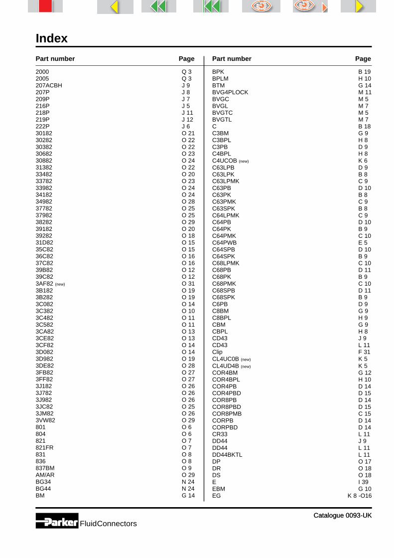
Index
Catalogue 0093-UK
2000 Q 32005 Q 3207ACBH J 9207P J 8209P J 7216P J 5218P J 11219P J 12222P J 630182 O 2130282 O 2230382 O 2230682 O 2330882 O 2431382 O 2233482 O 2033782 O 2333982 O 2434182 O 2434982 O 2837782 O 2537982 O 2538282 O 2939182 O 2039282 O 1831D82 O 1535C82 O 1536C82 O 1637C82 O 1639B82 O 1239C82 O 123AF82 (new) O 313B182 O 193B282 O 193C082 O 143C382 O 103C482 O 113C582 O 113CA82 O 133CE82 O 133CF82 O 143D082 O 143D982 O 193DE82 O 283FB82 O 273FF82 O 273J182 O 263J782 O 263J982 O 263JC82 O 253JM82 O 263VW82 O 29801 O 6804 O 6821 O 7821FR O 7831 O 8836 O 8837BM O 9AM/AR O 29BG34 N 24BG44 N 24BM G 14
BPK B 19BPLM H 10BTM G 14BVG4PLOCK M 11BVGC M 5BVGL M 7BVGTC M 5BVGTL M 7C B 18C3BM G 9C3BPL H 8C3PB D 9C4BPL H 8C4UCOB (new) K 6C63LPB D 9C63LPK B 8C63LPMK C 9C63PB D 10C63PK B 8C63PMK C 9C63SPK B 8C64LPMK C 9C64PB D 10C64PK B 9C64PMK C 10C64PWB E 5C64SPB D 10C64SPK B 9C68LPMK C 10C68PB D 11C68PK B 9C68PMK C 10C68SPB D 11C68SPK B 9C6PB D 9C8BM G 9C8BPL H 9CBM G 9CBPL H 8CD43 J 9CD43 L 11Clip F 31CL4UC0B (new) K 5CL4UD4B (new) K 5COR4BM G 12COR4BPL H 10COR4PB D 14COR4PBD D 15COR8PB D 14COR8PBD D 15COR8PMB C 15CORPB D 14CORPBD D 14CR33 L 11DD44 J 9DD44 L 11DD44BKTL L 11DP O 17DR O 18DS O 18E I 39EBM G 10EG K 8 -O16
Part number Page Part number Page
Catalogue 0093-UKFluidConnectors

Index
Catalogue 0093-UKCatalogue 0093-UKFluidConnectors
EG O 16EL I 19EPB D 11EPK B 10EPMFK C 11EPMK C 10EPWB E 6ET I 18EV K 8EV O 17EW I 17EW K 8EW O 17F23PB D 6F23PMB C 7F28PB D 6F28PMB C 7F3BM G 6F3BPL H 6F3H L 16F3PB B 6F3PB D 6F3PMB C 7F41H L 17F4BM G 6F4BPL H 7F4PB B 6F4PB D 7F4PMB C 7F4PWB E 4F4UCOB (new) K 5F4UF4UB (new) K 7F4UG4B (new) K 7F8BM G 7F8BPL H 7F8PB B 7F8PB D 7F8PMB C 8F8PWB E 4FBM G 6FBPL H 6FF J 5FF33 J 5FF33 L 6FF41G4 L 8FF44 J 5FF44 L 6FF633 L 7FF84 L 7FF88 L 7FG J 6FG43 J 6FG43 L 7FG44 L 8FG48 L 8FGH L 16FHG4 J 12FM I 32-33FN4 L 15FNM G 14FNPB D 16FNPB E 6FNPK B 19
FNPMK C 15FPB D 6G I 7G4BM G 8G4PB B 7G4PB D 8G4PMB C 8G8PMB C 8GBM G 7GE-M-ED I 12-13GE-R-ED I 10-11GE-UNF/UN I 14-15GG J 8GG44 J 8GG44 L 10GG84 L 10GG88 L 9GM I 36H897995 O 30H898202 O 30HBM G 7HBPL H 7HHP J 12HHP3 J 11HHP3 L 15HP J 11HP3 J 11HPB D 8HPK B 7HPMK C 8HPWB E 4HS3PK B 16J3PK B 16J5PK B 17J663PK B 17J664PK B 17J6PK B 17JBM G 10JBPL H 9JPB D 12JPK B 10-11JPMFK C 11JPMK C 11KBM G 12KMMOO4 J 10KMMOO4 L 13KMRO4434 L 13KRRS3 L 14LEE - UNF I 30LEE-M I 26LEE-R I 22M14-4C3 K 9M14-4C63 K 10M14-4F3 K 9M14-4F63 K 10M14-4V3 K 9M14-4V63 K 10MANI1 L 17MANI2 L 18MANIF L 17MBVG M 9M-DPR-D I 34-35MMO444 J 10
Part number Page Part number Page

Index
Catalogue 0093-UKCatalogue 0093-UKFluidConnectors
MMO444 L 12MMS443 J 10MMS443 L 12MRO434 J 10MRO434 L 13MRS433 L 12P40N L 15P4UN L 14P80N L 15Parker Teflon tape Q 4Par-Lok Q 3PB12EB N 6PB12F3C N 6PB12G4Z N 6PB12PL N 6PB13EB N 6PB13F3C N 6PB13G4Z N 6PB13PL N 6PB14EB N 6PB14F3C N 6PB14G4Z N 6PB14PL N 6PB52EB N 5PB52F3C N 5PB52G4Z N 5PB53F3C N 5PB53G4Z N 5PB54F3C N 5PB54G4Z N 5PBF52EB N 8PBF52F3C N 8PBF52G4Z N 8PBS251FB (new) N 10PBS251HB (new) N 10PBS251MB (new) N 10PBS371FB (new) N 10PBS371HB (new) N 10PBS371MB (new) N 10PBS501FB (new) N 10PBS501HB (new) N 10PBS501MB (new) N 10PBS502FB (new) N 11PBS502HB (new) N 11PBS502MBT (new) N 11PCF12EB N 22PCF12F3C N 22PCF12G4Z N 22PCF52EB N 21PCF52F3C N 21PCF52G4Z N 21PCV4 F 27PCV4PK F 27PE12EB N 14PE12F3C N 14PE12G4Z N 14PE12PL N 14PE52EB N 13PE52F3C N 13PE52G4Z N 13PEF12EB N 17PEF12F3C N 17PEF12G4Z N 17
PEF12PL N 17PEF13EB N 17PEF13F3C N 17PEF13G4Z N 17PEF13PL N 17PEF52EB N 16PEF52F3C N 16PEF52G4Z N 16PEF53EB N 16PEF53F3C N 16PEF53G4Z N 16PES251FB (new) N 19PES251HB (new) N 19PES251MB (neu) N 19PGauge F 31PIV4 F 27PIV4PK F 27Pneumo-Tube P 3PNM G 15Polyamide tubing P 4-5Polyurethane tubing P 6-7PRB4 F 29Prestoweld 2 tubing P 11PRI4 F 29PRIPB F 29PRB4PB F 29PRS F 30PTC Q 4PTF4 F 9PTF4E6PB F 11PTF4PB F 9PTF4PBW F 10PTF8E6PB F 11PTF8PB F 9PTFA4PB F 9PTFA8PB F 9PTFAC4PK (new) F 16PTFAC8PK (new) F 16PTFAL8 F 13PTFAL8PB F 12PTFALM8PK (new) F 17PTFC4PK (new) F 16PTFC8PK (new) F 16PTFIPK F 15PTFIWPK F 15PTFL4 F 13PTFL4COB F 13PTFL4PB F 13PTFL8 F 13PTFL8PB F 13PTFLAC4PK (new) F 17PTFLCKPK (new) F 16PTFLM8PK (new) F 17PTFMIPK F 15PTP4 F 25PTP4PB F 24PTP8 F 25PTP8PB F 24PTR J 7PTR34 J 6PTR34 L 8PTR44 L 9PTR44H L 9
Part number Page Part number Page

Index
Catalogue 0093-UKCatalogue 0093-UKFluidConnectors
PTR48 L 9PWAL (new) F 31PWB-A F 19PWE-A F 21PWPU (new) P 11PWR-HB F 23PWR-HE F 23PWS-B F 25PWS-E F 25PWS-M F 25R3BM G 11R3BPL H 9R63PB D 12R63PK B 11R63PMK C 12R64PB D 12R64PK B 11R64PMK C 12R68PB D 13R68PK B 12R68PMK C 12Ratchet F 31RBM G 10RBPL H 9RRD L 18RRO334 L 13RRP L 18RRS333 L 12S3BM G 11S3BPL H 10S4UCOB (new) K 6S63PB D 13S63PK B 13S63PMK C 12S64PB D 13S64PK B 13S64PMK C 13S68PB D 13S68PK B 13S68PMK C 13SBM G 11SBPL H 10SC4U D 15SC4UD D 15SC8U D 15SC8UD D 15SCM-150 I 40-43Splug F 31SV I 16SVGP Q 4T I 9T23FPK B 19T23FPMB C 16T23HF G 13T23HFPB D 16T23U G 15T24FPK B 19T24FPMB C 16T24HG G 14T28FPK B 20T28FPMB C 16T28HF G 13T2ESPK B 10
T2ESPMK C 11T2HF G 12T2HG G 13T2JJPK B 12T2JPK B 12TEE - UNF I 29TEE-M I 25TEE-R I 21TEPB D 16TE2PMK C 15Thermoplastic tube P 3TM G 15TR2PK B 20TR2PMK C 16TRBM G 15TRPB D 16TRPWB E 6TS2PK B 20Single tube and bundles P 9-10VEE-UNF I 31VEE-M I 27VEE-R I 23VKA I 37VSTI-R/M-ED I 38VW121 O 30VW39D (new) O 30W I 8WBM G 8WBMPB D 8WBMPB G 8WBPL H 7WE6PB D 11WE6PK B 10WEE-M I 24WEE-R I 20WEE-UNF I 28WGG44 L 10WG4PB D 8WGG44 J 9WPB D 9WPMB C 9WPWB E 5WYJ6PK B 14YGX/X-82 (new) K 6YGX/XCO (new) K 7YJ2PK B 14YJ2PMK C 14YJ52PK B 15YJ563PK B 15YJ564PK B 15YJ5PK B 14YJ63PK B 15YJ63PMK C 14YJ64PK B 16YJ68PMK C 15YJPK B 14YJPMFK C 14YJPMK C 13YMMM444 L 14YMMS443 L 14
Part number Page Part number Page

Parker’s CharterTo be a leading worldwide manufacturer of components andsystems for the builders and users of durable goods.More specifically, we will design, market and manufactureproducts controlling motion, flow and pressure. We will achieveprofitable growth through premier customer service.
Product InformationCustomers seeking product information, the location of a nearbydistributor, or repair services will receive prompt attention bycalling the Parker Product Information Centre.The Centre can be called toll free from France, Germany,Austria, Switzerland or the United Kingdom. You will beanswered by a Parker employee in your own language.Call Freephone: 00800 27 27 5374 (00800 C PARKER).
The Hydraulics Groupdesigns, produces and mar-kets a full spectrum ofhydraulic components andsystems to builders and usersof industrial and mobile ma-chinery and equipment.
The Automation Groupis a leading supplier of pneu-matic and electromechanicalcomponents and systems toautomation customers world-wide.
The Seal Group designs,manufactures and distributesindustrial and commercialsealing devices and relatedproducts by providingsuperior quality and totalcustomer satisfaction.
The Filtration Groupdesigns, manufactures andmarkets quality filtration andclarification products, provid-ing customers with the bestvalue, quality, technical sup-port, and global availability.
The InstrumentationGroup is a global leader inthe design, manufacture anddistribution of high-qualitycritical flow components forworldwide process instrumen-tation, ultra-high-purity, medi-cal and analytical applica-tions.
About Parker Hannifin CorporationParker Hannifin is a leading global motion-controlcompany dedicated to delivering premier customerservice.A Fortune 500 corporation listed on the New York StockExchange (PH), our components and systems comprise over1,400 product lines that control motion in some 1,000industrial and aerospace markets.Parker is the only manufacturer to offer its customers a choiceof hydraulic, pneumatic, and electromechanical motion-controlsolutions. Our Company has the largest distribution network inits field, with over 7,500 distributors serving nearly 400,000customers worldwide.
Parker Hannifin Corporation
The Aerospace Groupis a leader in the development,design, manufacture and ser-vicing of control systems andcomponents for aerospaceand related high-technologymarkets, while achievinggrowth through premiercustomer service.
The Climate & IndustrialControls Group designs,manufactures and marketssystem-control and fluid-handling components andsystems to refrigeration,air-conditioning and industrialcustomers worldwide.
The Fluid ConnectorsGroup designs, manufacturesand markets rigid and flexibleconnectors, and associatedproducts used in pneumaticand fluid systems.

Parker Hannifin GmbHBadener Straße 12A - 2700 Wiener NeustadtTel : (0) (26 22) 23 501Fax : (0) (26 22) 66 212
Parker Hannifin S.A.-N.V.Parc Industriel SudZone II15, rue du BosquetB - 1400 NivellesTel : (0) 67 280 900Fax : (0) 67 280 999
Parker Hannifin s.r.o.Dopravaku 723CZ - 184 00 Prague 8Tel : (0) (2) 830 85221Fax : (0) (2) 830 85360
Parker Hannifin GmbHGeschäftsbereich ErmetoAm Metallwerk 9D - 33659 BielefeldTel : (0) (521) 4048-0Fax : (0) (521) 4048-4280
Parker Hannifin GmbHFluid VerbindungsteileFreiherr-vom-Stein-Straße 1D - 35325 MückeTel : (0) (6400) 922-0Fax : (0) (6400) 922-102
Parker Hannifin GmbHGeschäftsbereich PolyflexAn der Tuchbleiche 4D - 68623 LampertheimTel : (0) (6256) 81-0Fax : (0) (6256) 81-100
Parker Hannifin Danmark A/SIndustrigrenen 11DK - 2635 IshøjTel : 43 56 04 00Fax : 43 73 31 07
Parker Hannifin A/SBerghagan - P.O. Box 8N - 1402 SkiTel : 64 91 10 00Fax : 64 91 10 90
Parker Hannifin B.V.Edisonstraat 1Postbus 340NL - 7570 AH OldenzaalTel : (0) 541 585000Fax : (0) 541 585459
Parker Hannifin Sp.z.o.o.ul. Parowcowa 8BPL - 02-445 WarszawaTel : (0) (22) 863 49 42Fax : (0) (22) 863 49 44
Parker Hannifin Portugal, LdaTravessa da Bataria,184 - r/c Drto / 1° Esq.PT - 4450-625 Leça da PalmeiraTel : 22 9997360Fax : 22 9961527
Parker Hannifin CorporationKomsomolsky Prospect 42Office 434RU - 119827 GSP MoscowG-48Tel/Fax : (095) 234 0054
Parker Hannifin ABFagerstagatan 51Box 8314S - 16308 Spånga-StockholmTel : (0) 8 5979 5000Fax : (0) 8 5979 5110
Parker Hannifin Corporationvul. Velyka Vasylkivska 9/2Office 59UA - 01004 KievTel: (80) (44) 2207 432Fax: (80) (44) 2206 534
Parker Hannifin España S.AP.I. Las Monjas -C/.Estaciones, 8E - 28850 Torrejón de Ardoz (Madrid)Tel : 91 675 73 00Fax : 91 675 77 11
Parker Hannifin SA17, Rue des BûchillonsZ.I. du Mt Blanc - BP 524F - 74112 Annemasse CedexTel : (0) 4 50 87 80 80Fax : (0) 4 50 37 86 85
Parker Hannifin OyYlästöntie 16FIN - 01510 VantaaTel : (0) (9) 476 731Fax : (0) (9) 476 732 00
Parker Hannifin plcHaydock Park RoadGB - Derby DE24 8JATel : (0) 1332 36 56 31Fax : (0) 1332 36 80 38
Parker Hannifin S.p.A.Via Privata Archimede 1I - 20094 Corsico (MI)Tel : 02 451921Fax : 02 4479340
Parker Sales Ireland LtdBracetown Business ParkClonee, County MeathIE - Republic of IrelandTel : (0) (1)801 4010Fax : (0) (1)801 4132
Parker Hannifin Corp.701, Gateway PlazaHiranandani Garden, PowaiIN - Mumbai 400076Tel: (0) (22)-5705881Fax: (0) (22)-5705880
Catalogue 0093-UK© 2002 Parker Hannifin
Triangle 01/2002
Parker Hannifin plcHaydock Park RoadDerby DE24 8JATel: (0)1332 36 56 31Fax: (0)1332 36 80 38
Internet: http://www.parker.com/europe/uk
For further information on other Parker Products, call the European Product Information Centrefree of charge on 00800 27 27 5374.
FluidConnectors EuropeSales Offices