pneuflot flotation technology - mbe coal & mineral …mbecoalandmineral.in/market/5.pdf ·...
TRANSCRIPT

pneuflot ® flotation technology
MBe Coal & Minerals teChnology gMBhformerly hUmBolDt WeDag coal & minerals technology gmBh

MBe Coal & Minerals teChnology gMBhformerly hUmBolDt WeDag coal & minerals technology gmBh
gottfried-hagen-str. 20, 51105 cologne / germanytel +49 221 99892 700 [email protected] www.mbe-cmt.de
Print rUn 1500concePt anD Design affairen-gestaltung.dePaPer euroBulkPrinteD By Kettler Verlag, BönenPrinteD in germany 2011

03
as the rich ore bodies are depleted, mineral industries need to go finer sizes for sellable products. therefore flotation is state-of-the-art processing method for many minerals.
this PneUflot brochure focuses on flotation technology, advantages of PneUflot and application examples. there is also information about PneUflot scales, test work possibilities and alternative areas where flotation can be applied.
many PneUflot plants are installed in the coal industry. With PneUflot technology coking coal and steam coal can be produced in a very economic and efficient way.
05 flotation technology 07 history of PneUmatic flotation 09 PrinciPle anD aPPlications 11 aUtomation 13 sizes anD facts 15 research anD DeVeloPment centre 19 scoPes of serVices
pneuflot ®flotation technology BrochUre

05
mechanical flotation machines are divided into agitation cells which receive air from blower or “self-aerating” machines which use the depression created by the impeller to induce air. Both types are characterised by a mechanically driven high-speed impeller which agitates the pulp and disperses fine air bubbles into it.
Pneumatic cells have no impeller and the pulp is “self-aerated” by creating a vacuum using the Venturi principle. flotation reagents are surface-active agents which selectively adhere to particle surfaces. they can intensify water-repelling (hydrophobic) properties or even reverse these properties, making the particles water-attracting (hydrophilic).
the former are known as “collectors”, the latter type reagents are called “depressors”. in addition, to influence selective adsorption, so-called “activators”, ph-adjusters and reagents with a dispersing effect are frequently used. tensides influence froth formation.
When particles with a water-repelling surface come into contact with air bubbles inside the flotation cell, they immediately attach themselves to the air bubbles and rise up to the pulp surface forming a froth layer. once the froth has built up it overflows and will be discharged from the top of the cell. the hydrophilic wetted particles are discharged in the underflow at the bottom of the cell.
to guarantee an efficient flotation process obviously there is an upper limit for the maximum particle size. most ores and minerals must be previously milled to achieve the required grain size, which is dictated by the intergrowth of the different components. nowadays the flotation process is also used for solid-liquid separation. especially in the field of waste water treatment, slow settling or suspended particles are collected by means of air bubbles and thickened in the froth phase.
pneuflot ®flotation technology
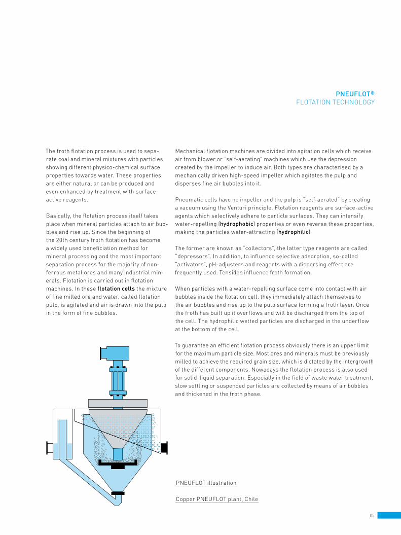
the froth flotation process is used to sepa - rate coal and mineral mixtures with particles showing different physico-chemical surface properties towards water. these properties are either natural or can be produced and even enhanced by treatment with surface-active reagents.
Basically, the flotation process itself takes place when mineral particles attach to air bub-bles and rise up. since the beginning of the 20th century froth flotation has be come a widely used beneficiation method for mineral processing and the most important separation process for the majority of non-ferrous metal ores and many industrial min-erals. flotation is carried out in flotation machines. in these flotation cells the mixture of fine milled ore and water, called flotation pulp, is agitated and air is drawn into the pulp in the form of fine bubbles.
PneUflot illustration
copper PneUflot plant, chile

07
in the first systems air entered through porous bottoms, cylinders or through nozzle pipes. this air served both for aeration as well as stabilisation of the pulp.
in terms of application technology the most important types of this first generation of pneumatic flotation cells were
– the Callow cell developed in 1914– the Mcintosh cell developed after 1925– the south-Western cell– the wish frother– the cyclone flotation 1949– the column cells– the Bahr cell 1980– PneUflot tangential type 1987– PneUflot new generation
after the 1980s Bahr cell was developed at the technical University of clausthal-zellerfeld in germany by Prof. Bahr. he was the inventor of a new exceptional technology which was patented and build for the first time in industrial scale from eKof in Bochum / germany. this technology was transferred and improved in the 1990s by the company KhD (Klöckner humboldt Deutz ag). since 2006 hUmBolDt WeDag coal & minerals technology gmbh and since 2009 mBe coal & minerals technology gmbh is manufacturing and developing PneUflot pneumatic flotation machines.
PneUflot has shown its efficiency in many mines around the world. after successful comparison studies and applications PneUflot has re placed its place from alternative to state of art nowadays. Briefly the energy consumption, the space and manpower requirements are considerably re duced by the application of PneUflot cells.
pneuflot ®
history of PneUmatic flotation
transport of 5-m PneUflot cells in chile to an iron plant
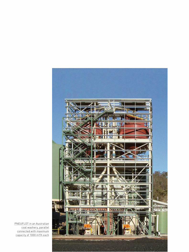
PneUflot in an australian coal washery, parallel
connected with maximum capacity of 1000 m3/h each

flotation With PneUflot. the flotation pulp is first directed to a single aerating unit arranged in the vertical pipe above the flotation cell. the aerator (self-aerated) is installed in the vertical feed pipe.
following aeration, the pulp flows through the central pipe to the slurry distributor ring located at the bottom of the cell where it is vertically deflected upward through high wear- resistant ceramic nozzles. the air bubbles covered with hydrophobic particles ascend to the upper cell area and form a froth layer on the surface which flows off into a froth launder surrounding the cell like a ring. Particles not cling-ing to air bubbles are discharged with the pulp from the bottommost point of the cell. the pulp level is kept constant either by a level probe which actuates a valve controlling the discharge or by a device known as a “gooseneck discharge”.
the kinetic energy required for adhesion at the bubble / particle interface is generated by the turbulent flow of the pulp in the aerator unlike any other technology which takes place in the vessel. the necessary flow rate and pressure are de livered by the appropriate slurry feed pump. the pulp distributor injects the aerated pulp in an upward motion into the flota-tion vessel. the cell is only responsible for separating the remaining pulp from the froth formed by the loaded bubbles.
09
pneuflot ®PrinciPle anD aPPlications
PneUflot is applicable for every flotation process where conventional flotation cells are considered such as:– coal (coking coal and steam coal)– sulfide non-ferrous metal ores such as copper ore,
lead / zinc ore, nickel ore– oxide ores such as iron ore, copper oxide ore, tin ore– industrial minerals such as phosphate, magnesite,
fluorspar, quartz, limestone– salt minerals such as potassium salt, rock salts, kieserite– paper and plastic waste recycling– disposal of fly ash and gypsum from flue gas
desulphurisation
self-aerating Units which do not require compressed air have been developed for the PneUflot technology. the slurry is pressed through small wear-proof ceramic nozzles distributed in circles pointing to a large Venturi and thus creating a vacuum when the pulp is pumped through it. this effect pulls air into the pulp. the circular arrangement of the nozzles distributes the pulp flow creating the neces sary turbulence for intensive air bubble / mineral particle contact.
these aerators are offered in various sizes to suit different pulp flow rates and different mineral throughputs. therefore only one aerator unit per flotation cell is needed to achieve high performance.
self-aspirating aerators can be also controlled automatically
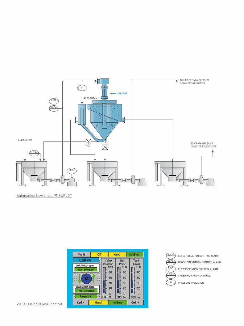
automation flow sheet PneUflot
Visualisation of level control
GOOSENECK
TO FROTH PRODUCT DEWATERING SECTION
TO UNDERFLOW PRODUCTDEWATERING SECTION
FEED SLURRY
AERATOR
LEVEL INDICATION CONTROL ALARM
DENSITY INDICATION CONTROL ALARM
FLOW INDICATION CONTROL ALARM
SPEED INDICATION CONTROL
PRESSURE INDICATION
SIC
DICA
FICA
LICA
LICA
DICA
FICA
SIC
Pi
Pi
GOOSENECK
TO FROTH PRODUCT DEWATERING SECTION
TO UNDERFLOW PRODUCTDEWATERING SECTION
FEED SLURRY
AERATOR
LEVEL INDICATION CONTROL ALARM
DENSITY INDICATION CONTROL ALARM
FLOW INDICATION CONTROL ALARM
SPEED INDICATION CONTROL
PRESSURE INDICATION
SIC
DICA
FICA
LICA
LICA
DICA
FICA
SIC
Pi
Pi

11
With a very few control loops a high-efficient process is realised:
1 the level of the feed tank will be controlled by recirculation underflow slurry of the PneUflot cell. a constant feed pressure of 2,2 – 2,8 bar to the PneUflot will be required while running the machine.
2 the reagent dosing will be controlled by a flow meter and a density device in the feed pipe to the aerator. according to a given set point the frequency converter of the dosing pump will be controlled.
3 the feed pressure to the PneUflot is controlled by the speed of the centrifugal feed pump in case of using a frequency converter. in this case the air bubble size can be influenced. higher slurry velocity leads to smaller air bubbles in the aerator.
4 in case of coal flotation the drain valve underneath the PneUflot is closed all the time. in case of ore minerals flotation the drain valve has to be opened to a given set pointto avoid blockage due to sedimentation of coarse particles.
11
pneuflot ®aUtomation
Dosing station – one system for each dosing point
DOSING
SAMPLING
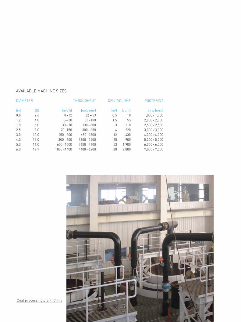
aVailaBle machine sizes
Diameter throUghPUt cell VolUme footPrint (m) (ft) (m3 / h) (gal / min) (m3) (cu ft) l × w (mm)0.8 2.6 8 –12 26 – 53 0.5 18 1,000 × 1,0001.2 4.0 15 – 30 53 –130 1.5 55 2,000 × 2,0001.8 6.0 30 – 70 130 – 300 3 110 2,500 × 2,5002.5 8.0 70 –150 300 – 650 6 220 3,000 × 3,0003.0 10.0 150 – 300 650 –1300 12 430 4,000 × 4,0004.0 13.0 300 – 600 1300 – 2400 25 900 5,000 × 5,000 5.0 16.0 600 –1000 2600 – 4400 53 1,900 6,000 × 6,0006.0 19.7 1000 –1400 4400 – 6200 80 2,800 7,000 × 7,000
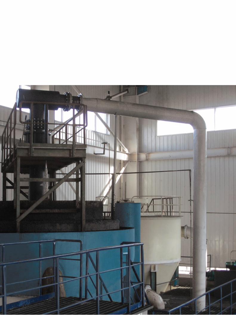
coal processing plant, china

for the process:– better recovery and more yield because of optimal particle and
bubble contact– higher selectivity with optimal control of air – no re-sliming because of less shear force– air bubble size can be influenced– small air bubbles for fine material or bigger air bubbles for coarse feed
material can be produced with the same aerator design
economical advantages:– less wear thanks to absence of agitator and the modern materials,
e. g. hard ceramics– low energy since only a pump is required– no compressed air required on account of the new
self-aspirating aerator technology– small footprint because the particle and bubble contact has occurred
before the pulp is injected to the separation vessel, furthermore this is also causing less reagent consumption and less number of cells
– identical cell design for all applications because of the wide range of the bubble size that can be produced by the PneUflot (5 –1,000 μm accumulated at 300 μm)
operational advantages:– flexible flotation circuit balance with help of automatic recirculation
of downcomers– optimal froth control with adjustable “gooseneck” and “froth crowder”– simple control through online monitoring of the process parameters
such as air volume, pressure and tank level– robust and non-sensitive to feed alteration
13
pneuflot ®sizes anD facts

PneUflot laboratory plant
PneUflot pilot plant

test WorK PossiBilities With PneUflot. for many applications doing a flotation test is obligatory for determining the process. since the air injection to slurry is done in a very small area before the separation vessel, the PneUflot process needs less time compared to other flotation technologies. to design the process and assure the operation, we suggest to do test works with PneUflot itself.
small scale tests are carried out with a laboratory PneUflot. Bigger test works, on-site works, comparison studies or pilot productions are carried out with our smallest production machine which can handle up to 12 m3 / h.
the plug-and-run pilot plant can be delivered with its 20-feet container worldwide on a rental basis.
a questionnaire for flotation as well as a data sheet for the PneUflot pilot plant will be sent on request.
the pilot plant is fully equipped with all pumps and the feed agitator tank for proper operation. the power demand for the complete unit is 15 kW.
researCh and developMent Centre
15

451 1052
GOOSENECK
AERATOR
GOOSENECK
AERATOR
GOOSENECK
FINAL TAILINGS
AERATOR
1.29
.
0.66
20
408 8911.3 0.04
32
GOOSENECK
FINAL TAILINGS
SCAVENGER 2 (1 PNEUFLOT 4M, DIA)
PROCESSWATER
AERATOR
68 4741.1 0.22
40
t/h m³/ht/m³ % Cu
406 6321.48 6.55
35 86 5821.11 1.58
38
43 1611.12 6.52
3318 109
1.12 6.7
41
302 2022.11 6.55
34
104 4521.17 6.55
36
AERATOR
GOOSENECK
AERATOR
PROCESSWATER
36 1201.23 20
4218 62
1.22 30
43
451 1052
GOOSENECK
AERATOR
GOOSENECK
AERATOR
GOOSENECK
FINAL TAILINGS
AERATOR
1.29 0.66
20
408 8911.3 0.04
32
43 1611.12 6.52
33
GOOSENECK
example for copper processing with PneUflot technology
451 1052
GOOSENECK
AERATOR
GOOSENECK
AERATOR
GOOSENECK
FINAL TAILINGS
AERATOR
1.29
.
0.66
20
408 8911.3 0.04
32
GOOSENECK
FINAL TAILINGS
SCAVENGER 2 (1 PNEUFLOT 4M, DIA)
PROCESSWATER
AERATOR
68 4741.1 0.22
40
t/h m³/ht/m³ % Cu
406 6321.48 6.55
35 86 5821.11 1.58
38
43 1611.12 6.52
3318 109
1.12 6.7
41
302 2022.11 6.55
34
104 4521.17 6.55
36
AERATOR
GOOSENECK
AERATOR
PROCESSWATER
36 1201.23 20
4218 62
1.22 30
43
451 1052
GOOSENECK
AERATOR
GOOSENECK
AERATOR
GOOSENECK
FINAL TAILINGS
AERATOR
1.29 0.66
20
408 8911.3 0.04
32
43 1611.12 6.52
33
GOOSENECK

17
451 1052
GOOSENECK
AERATOR
GOOSENECK
AERATOR
GOOSENECK
FINAL TAILINGS
AERATOR
1.29
.
0.66
20
408 8911.3 0.04
32
GOOSENECK
FINAL TAILINGS
SCAVENGER 2 (1 PNEUFLOT 4M, DIA)
PROCESSWATER
AERATOR
68 4741.1 0.22
40
t/h m³/ht/m³ % Cu
406 6321.48 6.55
35 86 5821.11 1.58
38
43 1611.12 6.52
3318 109
1.12 6.7
41
302 2022.11 6.55
34
104 4521.17 6.55
36
AERATOR
GOOSENECK
AERATOR
PROCESSWATER
36 1201.23 20
4218 62
1.22 30
43
451 1052
GOOSENECK
AERATOR
GOOSENECK
AERATOR
GOOSENECK
FINAL TAILINGS
AERATOR
1.29 0.66
20
408 8911.3 0.04
32
43 1611.12 6.52
33
GOOSENECK

19
from the first steP UP to the commissioning. to realise your projects you can receive the entire scope of services from one source, i. e. from us:project consulting by globally experienced mining, process, mechanical engineers and mineralogists.test work in our own r&D centre and laboratories and at your plant.feasibility studies in joint effort of clients’ personnel familiar with the project targets and our competent employees, even up to project financing.plant design with basic and detail engineering including project management.supply of equipment, systems and plants.training of end users’ personnel for management functions same as for oper a tors and maintenance employees, in our offices, in our r&D centre, in our reference plants all over the world and finally on end users’ site.installation / supervision of installation of our equipment and systems by our own globally experienced service specialists.Commissioning of equipment, systems and plants.after-sales services including not only supply of parts and respective services but also consultancy in respect of operation and maintenance of our equipment.
after-sales serVice. Utilising our considerable logistical, engineering and site- service expertise, mBe coal & minerals technology gmbh aim to provide an unpar-alleled level of ongoing services. these services will maximise the operators’ return on their investment throughout the lifetime of the equipment.
We believe that strong partnerships can only evolve with personal contact. from the outset we have assigned an account manager who will learn about your business and understand its unique demands. Utilising that knowledge and by focussing on what is important to each individual customer, we can develop an operational plan that will ensure we deliver on our promises – on time and within budget.
the four key services we offer to maintain and improve the operation of your equipment:– competitively priced oem spare parts with
lead times to meet the customers’ opera-ting requirements
– we carry out planned service visits at mutually agreed intervals with an optional emergency call-out service and operator training
– upgrade packages for your equipment to improve performance, based on our most recent product developments
– equipment refurbishment
continue to utilise our people and expertise to maximise the efficiency of your operations. “We will not let you down.”
sCopes of serviCes
PneUflot plant in operation

MBE Minerals SA Pty. Limited36 Wankel Street Jet Park Boksburg 1459PO Box 8460 Elandsfontein 1406 / South AfricaTel +27 11 3974660, Fax +27 11 3974411 [email protected]
McNally Humboldt Wedag Minerals India Pvt. Ltd.Ecospace Campus, 3rd Floor, -2B, 11F / 2New Town Rajarhat, North 24 Parganas Kolkata 700156 / IndiaTel +91 33 66281111 / 30141111, Fax +91 33 30142234 / 66282234 [email protected]
MBE Minerals Processing Technology Beijing Co. Ltd.c/o KHD Humboldt Wedag International Beijing Office25 A CITIC Building, 19 Jianguomenwai Dajie, Beijing China 100004Tel +86 10 65004101, Fax +86 10 65008623 [email protected]
MBE Coal & Minerals Technology GmbHRepresentative office in MoscowMyasnitskaya str, bld.1 24 / 7, Office 108, 101000 MoscowTel +7 495 6251844, Fax +7 495 9894125 [email protected]
MBE Processamento Mineral do Brasil Ltda.Rua Rio Grande do Norte No. 1560 – salas 701 e 702CEO. 30.130.131 Belo Horizonte, MG / BrasilTel +55 31 37855224, Fax +55 31 37860857 [email protected]
MBE Cologne Engineering GmbHDillenburger Str. 63, 51105 Cologne / GermanyTel +49 221 99892600, Fax +49 221 99892619 [email protected]
McNally Bharat Engineering Company Limited Head OfficeEcospace 11F / 12, Old Plot No. AA II / Blk 3, New Town RajarhatNorth 24 Parganas Kolkata 700156 / IndiaTel +91 33 66281111 / 30141111, Fax +91 33 66282277 / 30142277 [email protected]
gottfried-hagen-str. 20, 51105 cologne / germany tel +49 221 99892700, fax +49 221 99892709 [email protected]
MBe Coal & Minerals teChnology gMBhformerly hUmBolDt WeDag coal & minerals technology gmBh