p/n: 833620-00 - shadin avionics
TRANSCRIPT

AIS-360 AIRCRAFT INTERFACE MODULE
P/N: 833620-00
INSTALLATION MANUAL
MANUAL P/N: M833620-00
REV A
Shadin Avionics 6831 Oxford Street
St. Louis Park, MN 55426 USA
Sales: (800) 328-0584
Customer Service: (800) 388-2849 or (952) 927-6500
www.shadin.com [email protected]

M833620-00 Shadin Avionics
INSTALLATION MANUAL AIS-360 AIRCRAFT INTERFACE MODULE
Rev: A P/N 833620-00 Page: 2 of 15
Shadin Avionics 6831 Oxford Street St. Louis Park, MN 55426 USA
Revision Log
REV DATE APP’D CHANGE CVS Version
– 05/30/13 RJW Baseline Release 2.0 A 07/01/13 TJO Updated output with NMEA description, removed
software verification descriptions from Section 3.2 and renumbered paragraphs
3.0

M833620-00 Shadin Avionics
INSTALLATION MANUAL AIS-360 AIRCRAFT INTERFACE MODULE
Rev: A P/N 833620-00 Page: 3 of 15
Shadin Avionics 6831 Oxford Street St. Louis Park, MN 55426 USA
Table of Contents
Revision Log 2
1 OVERVIEW 4
2 INSTALLATION PROCEDURE 7
3 SETTING THE AIM CONFIGURATION 9
4 ENVIRONMENTAL QUALIFICATION FORM (EQF) 13
5 INSTALLATION DRAWINGS AND INSTALL KIT PARTS LIST 15

M833620-00 Shadin Avionics
INSTALLATION MANUAL AIS-360 AIRCRAFT INTERFACE MODULE
Rev: A P/N 833620-00 Page: 4 of 15
Shadin Avionics 6831 Oxford Street St. Louis Park, MN 55426 USA
The information in this manual is subject to change without notification.
1 OVERVIEW 1.1 THE MANUAL This manual is intended to determine a proper installation of the AIS-360 AIRCRAFT INTERFACE MODULE (AIM). Installation instructions should be read and followed. 1.2 PRODUCT DESCRIPTION The AIM, Shadin Avionics part number 833620-00, provides the interface between aircraft ARINC 429 data busses and two customer tablet devices. Aircraft data is accepted on two ARINC 429 busses which are connected to the aircraft Flight Management System (FMS) or other aircraft avionics. ARINC data from the aircraft is used to build GPGGA and GPRMC NMEA GPS (defined in section 1.5) message strings, which are sent to the tablet devices to provide current location data. Additionally, applications on the consumer devices can request to receive ARINC data from the AIM. Communication between the consumer devices and the AIM utilizes standard serial ports. Discrete digital input and output ports are used to detect the connection of a device to the AIM and signal the connection of the AIM to the device. When connected, the AIM must first complete an identification and authentication process. After authentication is complete, location data is provided to the device. This location data is available to any application on the device. A Software Development Kit (SDK) allows applications running on the EFB (Electronic Flight Bag) to communicate with the AIM. This communication includes the ability to configure the reception of specific ARINC labels and the rate at which that data is sent to the application. A block diagram of the system follows.
Aircraft Interface Module(AIM)
Pilot EFB
Serial Data
Discrete Co-Pilot EFB
Serial Data
Discrete
RS-232 (Maint Use
Only)
Discrete
Discrete
Arinc 429 HS/LS
Arinc 429 HS/LS
Aircraft Power 28 VDC

M833620-00 Shadin Avionics
INSTALLATION MANUAL AIS-360 AIRCRAFT INTERFACE MODULE
Rev: A P/N 833620-00 Page: 5 of 15
Shadin Avionics 6831 Oxford Street St. Louis Park, MN 55426 USA
1.3 SPECIFICATIONS Physical Specifications Dimensions: 1.57H x 6.90L x 4.24W (inches)
Weight: 0.7 lbs. Electrical and Functional Power Supply Voltage: +28VDC Nominal Supply Current (No Loads): 100 mA at 28 VDC Supply Current Typical (With Loads): 600 mA at 28 VDC Environmental RTCA/DO-160F (by similarity to P/N 833811-00) Categories: [A4X]BBB[R(B,B1) U2(F,F1)]XXXXXXZ[BXX]AZ[CC][RR]M[XXJ33]XXAX Operating Temperature: -40° to +70°C Operating Altitude: Up to 42,000 ft Storage Temperature: -55° to +85°C In-Flight loss of Cooling: Equipment can run indefinitely with no cooling Regulatory: TSO-C115c INCOMPLETE SYSTEM MIL-HDBK-217 MTBF: greater than 20,000 hours MTBF Definition: Mean time between failures (MTBF) is calculated following MIL-HDBK-217 guidance as a starting point, when available field or vendor data is used in place of MIL-HDBK-217 predictions. The AIS-380 prediction is for an environment of airborne, inhabited, cargo. At 20°C the prediction is 36,367 hours and at 40°C it is 22,607 hours.

M833620-00 Shadin Avionics
INSTALLATION MANUAL AIS-360 AIRCRAFT INTERFACE MODULE
Rev: A P/N 833620-00 Page: 6 of 15
Shadin Avionics 6831 Oxford Street St. Louis Park, MN 55426 USA
1.4 INPUTS The AIM accepts ARINC 429 data and passes the data through to the tablet interface. The AIM has the ability to be customized to filter or ignore specific labels. The following inputs are provided:
• Two ARINC-429 inputs configurable for high or low speed • One RS-232 interface for ground maintenance • One RS-232 receive/transmit interface for Pilot EFB communication • One RS-232 receive/transmit interface for Co-Pilot EFB communication • Two Discrete Inputs which accept the following signal levels:
1.5 OUTPUTS The AIM provides serial data to the EFB. This data is conditioned and provided to the SDK interface which accepts it into the flight bag application.
• Two RS-232 transmit interfaces for EFB communication (one per EFB) • Two discrete outputs for the Accessory Detect signal (Open/Ground type). Each output has a
maximum current rating of 0.5 amps. Time, latitude, longitude, and speed are gathered from the ARINC bus and put into NMEA GPGGA and GPRMC format for the EFB to receive.
NMEA GPGGA NMEA GPRMC Time (UTC) Time (UTC) Latitude Status North or South Latitude Longitude North or South East or West Longitude GPS Quality Indicator East or West Number of satellites in view Speed over ground, knots Horizontal Dilution of Precision Track made, good, degrees true Antenna Altitude above/below mean-sea-level (geoid) Date, ddmmyy Unites of antenna altitude, meters Magnetic variation, degrees Geoidal separation East or West Units of geoidal separation, meters Checksum Age of differential GPS data Differential reference station ID Checksum
NMEA messages are ASCII comma separated strings as seen in the example below. GPGGA: $--GGA,hhmmss.ss,llll.ll,a,yyyy.yy,a,x,xx,x.x,x.x,M,x.x,M,x.x,xxxx*hh GPRMC: $--RMC,hhmmss.ss,A,llll.ll,a,yyyy.yy,a,x.x,x.x,xxxx,x.x,a*hh
Discrete Input State Voltage/Resistance Levels Low/Ground Signal (Active) V < 3.5 VDC (with I < 20mA sink)
R, 10 ohms High/Open Signal (Inactive) 5 VDC < V < 33 VDC
R > 100 Kohms

M833620-00 Shadin Avionics
INSTALLATION MANUAL AIS-360 AIRCRAFT INTERFACE MODULE
Rev: A P/N 833620-00 Page: 7 of 15
Shadin Avionics 6831 Oxford Street St. Louis Park, MN 55426 USA
2 INSTALLATION PROCEDURE 2.1 LIMITATIONS This equipment is developed to RTCA/DO-178B Design Assurance Level C. The Equipment acts as an extension of the output of the Flight Management System (FMS) only and is therefore certified as an “Incomplete system”. The AIM does not output any data back to the FMS. The output of the AIM is intended to be used for supplemental data to the flight crew and the installer is responsible for ensuring the certification levels are appropriate for the application through a system safety analysis. 2.2 MOUNTING The AIS-360 AIRCRAFT INTERFACE MODULE (P/N 833620-00) should be mounted according to the installation drawing given in Appendix A. The equipment should be installed in a controlled temperature and pressurized location. The unit can be mounted in any orientation in the aircraft.

M833620-00 Shadin Avionics
INSTALLATION MANUAL AIS-360 AIRCRAFT INTERFACE MODULE
Rev: A P/N 833620-00 Page: 8 of 15
Shadin Avionics 6831 Oxford Street St. Louis Park, MN 55426 USA
2.3 ELECTRICAL CONNECTIONS Installation Drawing D833620-00 provides connector J1 pinout information. Typical electrical wiring is shown below.
RX 1 A
RX 1 B
RX 2 A
RX 2 B
40
41
27
12
TX
RX
20
21
TXRX
34
19
37
1721 16
+ 28 VDC
ARINC 429Input 1
ARINC 429 Source 1
ARINC 429Source 2
ARINC 429Input 2
SerialRS-232
Port 2
SerialRS-232Port 1
Serial 1(Maintenance)
TX
RX
31
7
Discrete Input(I/O Port 1)
28 RTN
+ +28 V POWER
SerialRS-232
Port 3
Device Detect5
22
AircraftInterfaceModule(AIM)
PilotEFB
Co-Pilot EFB
Discrete Output(I/O Port 4)
Discrete Input(I/O Port 3)
Device Detect
Accessory Detect
6
23
Discrete Output(I/O Port 2)
Accessory Detect
2.4 INSTALLATION NOTES Aircraft power +28 VDC can be connected to both pins 2 and 17 for redundancy as shown above. Alternatively the unit can be powered only through pin 2, or only through pin 17. The same applies to the return lines: Pins 1 and 16 can both routed to the aircraft 28 V return, or return can be connected to either pin 1 or pin 16. Pin 37 is tied directly to the AIM chassis. After the AIM is mounted to the airframe, this pin is equivalent to airframe ground and can be used as a connection to cable shields in the connector backshell. The EFBs are powered separately from the AIM. The power source provides the common ground connection for the interface signals.

M833620-00 Shadin Avionics
INSTALLATION MANUAL AIS-360 AIRCRAFT INTERFACE MODULE
Rev: A P/N 833620-00 Page: 9 of 15
Shadin Avionics 6831 Oxford Street St. Louis Park, MN 55426 USA
3 SETTING THE AIM CONFIGURATION This section describes the method of setting the AIM configuration through the maintenance port Serial 1. The AIM is to be configured on a test bench prior to installation in the aircraft. The ARINC port configuration is given below as well as other functions that may be useful. Below is a list of the equipment needed. Equipment List
• +18 V to +28 V DC Power Supply • Desktop or Laptop PC with serial port or USB
adapter if no serial port is available • 833620-00 AIS-360 Aircraft Interface Module
A cable configured per the figure below can be built to interface the AIM to the PC. Alternatively, a cable assembly can be acquired from Shadin Tech Support per the contact information below:
Web: www.shadin.com E-mail: [email protected] Phone: (952) 927-6500 or
(800) 388-2849
Field Configuration Cable

M833620-00 Shadin Avionics
INSTALLATION MANUAL AIS-360 AIRCRAFT INTERFACE MODULE
Rev: A P/N 833620-00 Page: 10 of 15
Shadin Avionics 6831 Oxford Street St. Louis Park, MN 55426 USA
3.1 COMMUNICATION INTERFACE Communication between the AIM and the maintenance device occurs on RS-232 serial port 1 of the AIM Device. The port is configured for 115200 baud, 8 data bits, No parity, and 1 stop bit. The AIM interface will utilize ANSI escape sequences to clear the terminal screen and reset the cursor to the home position. For optimum readability, the maintenance device terminal program should be set to emulate an ANSI terminal. Additionally, the maintenance device should be set to display sent characters (Half Duplex), as the AIM does not echo received characters. Data input to the AIM will only be processed when the AIM receives the carriage return character (0x0D), which can be sent from most terminal programs by pressing the ‘Enter’ key.
3.2 MAINTENANCE PORT SCREEN DISPLAYS AIM maintenance and configuration screen displays are shown below. Almost any terminal emulation program can be used. The maintenance port window has additional options that were used during software verification. In the paragraphs that follow are the options used during aircraft installation and configuration. Setting up Connection
1. Connect the field configuration cable to the PC and AIM. 2. Connect power leads to +28 VDC and turn power on. 3. Start terminal emulation program and enter the following configuration:
a. Set the com port that is connected to serial port 1 of the AIM. b. Port parameters to:
• 115200 baud • no parity • 8 data bits • 1 stop bit • no flow control
4. Set Display parameters to display as Ansi, Half Duplex, 5. Press “Enter”. With the AIM running the Main Menu will be displayed. 6. Use the available options shown for viewing and controlling AIM configuration and maintenance. 7. Selecting options consists of typing single digit numbers followed by “Enter”.

M833620-00 Shadin Avionics
INSTALLATION MANUAL AIS-360 AIRCRAFT INTERFACE MODULE
Rev: A P/N 833620-00 Page: 11 of 15
Shadin Avionics 6831 Oxford Street St. Louis Park, MN 55426 USA
3.2.1 MAIN MENU DISPLAY
Figure 1 – Main Menu Display
The main menu will be displayed when the AIM receives a carriage return (hex character 0x0D). Selection of the main menu options will be accomplished by sending the number corresponding to the desired option followed by a carriage return.
3.2.2 PART NUMBER DISPLAY
Figure 2 – Part Number Display
The part number display will be accessed by entering 1 from the main menu. This option will display the hardware and software part numbers. Sending a carriage return will re-display the main menu.
3.2.3 CONFIGURATION DISPLAY
Figure 3 – Configuration Display
The current configuration will be displayed by entering 2 from the main menu. This option will display the current ARINC and EFB configuration. Sending 1 or 2, followed by a carriage return, will display menus to modify the configuration table.
M833620-00 Shadin Avionics
INSTALLATION MANUAL AIS-360 AIRCRAFT INTERFACE MODULE
Rev: A P/N 833620-00 Page: 12 of 15
Shadin Avionics 6831 Oxford Street St. Louis Park, MN 55426 USA
Sending 3, followed by a carriage return, will clear the configuration table. Sending any other characters (or no characters) and a carriage return will re-display the main menu. The example in Figure 3 is from an configured unit. Based on previous configurations data may be populated for Channel 1 and 2, and EFB 1 and 2.
3.2.4 MODIFYING ARINC SETTINGS
Figure 4 – Modifying ARINC Settings
Sending 1 from the configuration menu will display the ARINC configuration options. The configuration of an ARINC channel will be set by sending the channel number, space, selection number, and carriage return. The configuration menu will be re-displayed, without changing the configuration, if any other characters (or no characters) and a carriage return are sent.
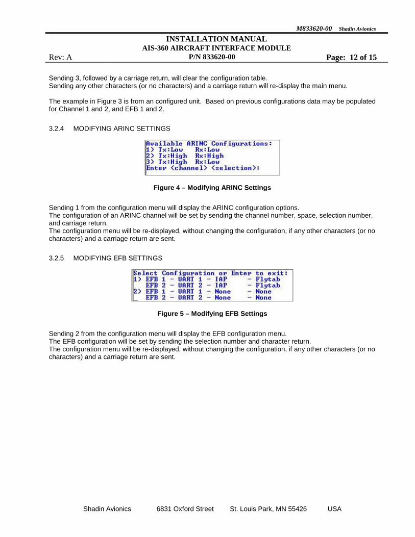
3.2.5 MODIFYING EFB SETTINGS
Figure 5 – Modifying EFB Settings
Sending 2 from the configuration menu will display the EFB configuration menu. The EFB configuration will be set by sending the selection number and character return. The configuration menu will be re-displayed, without changing the configuration, if any other characters (or no characters) and a carriage return are sent.

M833620-00 Shadin Avionics
INSTALLATION MANUAL AIS-360 AIRCRAFT INTERFACE MODULE
Rev: A P/N 833620-00 Page: 13 of 15
Shadin Avionics 6831 Oxford Street St. Louis Park, MN 55426 USA
4 ENVIRONMENTAL QUALIFICATION FORM (EQF) This Environmental Qualification Form describes qualification testing performed on the 833811-00. The 833620-00 uses identical hardware and is qualified by similarity to the P/N 833811-00. The 833620-00 is therefore qualified to RTCA/DO-160F standards. NOMENCLATURE: AIS-380 FUEL FLOW ADAPTER TYPE/MODEL/PART NO: 833811-00 MANUFACTURER'S SPECIFICATION AND/OR OTHER APPLICABLE SPECIFICATION: Report SD-110037, RTCA/DO-160F MANUFACTURER: Shadin Avionics ADDRESS: 6831 Oxford Street, St. Louis Park, Minnesota 55426-4412 CONDITIONS SECTION DESCRIPTION OF
TESTS CONDUCTED Temperature and Altitude 4.0 (1) Tested to Category A4X See remarks
Low Temperature High Temperature
4.5.1, 4.5.2 4.5.3, 4.5.4
-40˚C +70˚C
Altitude Decompression Overpressure
4.6.1 4.6.2 4.6.3
(2) +42,000 ft (See remarks) (2) +42,000 ft (See remarks) -15,000 ft
Temperature Variation
5.0 Tested to Category B
Humidity
6.0 Tested to Category B
Operational Shock and Crash Safety
7.0
Tested to Category B
Vibration
8.0 Tested to Category R (B, B1), U2(F, F1)
Explosion 9.0 Identified as Category X Not tested
Waterproofness 10.0 Identified as Category X
Not tested Fluids Susceptibility 11.0 Identified as Category X
Not tested

M833620-00 Shadin Avionics
INSTALLATION MANUAL AIS-360 AIRCRAFT INTERFACE MODULE
Rev: A P/N 833620-00 Page: 14 of 15
Shadin Avionics 6831 Oxford Street St. Louis Park, MN 55426 USA
ENVIRONMENTAL QUALIFICATION FORM (Cont.) CONDITIONS SECTION DESCRIPTION OF
TESTS CONDUCTED Sand and Dust 12.0 Identified as Category X
Not tested Fungus 13.0 Identified as Category X
Not tested Salt Spray 14.0 Identified as Category X
Not tested Magnetic Effect 15.0 Tested to Category Z Power Input 16.0 Tested to Category BXX Voltage Spike 17.0 Tested to Category A Audio Frequency Susceptibility 18.0 Tested to Category Z Induced Signal Susceptibility 19.0 Tested to Category CC Radio Frequency Susceptibility 20.0 Tested to Category RR Radio Frequency Emission 21.0 Tested to Category M Lightning Induced Transient Susceptibility 22.0 Tested to Category XXJ33
Lightning Direct Effects 23.0 Identified as Category X
Not tested. Icing 24.0 Identified as Category X
Not tested. Electrostatic Discharge 25.0 Tested to Category A
Fire, Flammability 26.0 Identified as Category X
Not tested. REMARKS: (1) The 833811-00 was tested to -40°C, beyond the normal A4 category temperature limits. (2) The 833811-00 was tested to +42,000 ft, beyond the normal A4 category altitude and decompression limits.

M833620-00 Shadin Avionics
INSTALLATION MANUAL AIS-360 AIRCRAFT INTERFACE MODULE
Rev: A P/N 833620-00 Page: 15 of 15
Shadin Avionics 6831 Oxford Street St. Louis Park, MN 55426 USA
5 INSTALLATION DRAWINGS AND INSTALL KIT PARTS LIST Appendix A: INSTALLATION DRAWING – D833620-00 Appendix B: INSTALL KIT, PARTS LIST – K833811-00


Shadin Avionics CAGE CODE: 0Z5P5
File Name: K833811-00-.DOC
ERN #: 1302/004
Rev: – Release Date: 2013/02/14
Approved: ZK
Page 1 of 1
PARTS LIST Part #: K833811-00
Drawing #s: NA Description: INSTALL KIT, AIS 833811-00
FN P/N QTY. DESCRIPTION MFG. MFG.# DESIGNATION COMMENTS
Shadin Avionics Proprietary Information - ALL RIGHTS RESERVED
5 232012 1 CONN, HD D-Sub 44 Pin, Female Crimp w/FC8022D2
Contacts
POS ODD44S1000X
10 232507 1 CONN, Backshell, 25P D-Sub, Zinc Die Cast APH 17E-1657-25
15 239004 1 TOOL, INSERT/EXTRACT M81969/1-04 NWK 59K0052
20 753217 1 Thermal Label, 4"x 1" ULI S-8601
25 PK1001 2 BAG, 2.5 x 3, 4 MIL Zip Lock
30 PK1007 1 BAG, 6 x 8, 4 MIL
7 items