p/n 301-30 rev. ss - x-rite · p/n 301-30 rev. ss corporate headquarters x-rite, incorporated 4300...
TRANSCRIPT

P/N 301-30 Rev. SS
Corporate Headquarters X-Rite, Incorporated 4300 44th Street SE Grand Rapids, Michigan 49512 Phone 1 800 248 9748 or 1 616 803 2100 Fax 1 800 292 4437 or 1 616 803 2705 European Headquarters X-Rite Europe GmbH Althardstrasse 70 8105 Regensdorf Switzerland Phone (+41) 44 842 24 00 Fax (+41) 44 842 22 22 Asia Pacific Headquarters X-Rite Asia Pacific Limited Suite 2801, 28th Floor, AXA Tower Landmark East, 100 How Ming Street Kwun Tong, Kowloon, Hong Kong Phone (852)2568-6283 Fax (852)2885 8610 Please visit www.xrite.com for a local office near you.


Output Connection
14
DATA INSTRUCTION FORMAT Data is sent in the following format:
<Lead Character><Units><Tenths><Hundredths><Carriage Return>
Lead Character represents the ASCII code for a positive character (space) or negative character (–).
Units, Tenths, & Hundredths are three ASCII digits (0-9) representing density values.
Data is transmitted at the rate of 300 baud with one start bit and stop bit, and the parity bit set to logic zero.
Output logic level is −5Vdc to +5Vdc
DTE (Pin 2 = TRANSMIT)
DCE (Pin 3 = TRANSMIT)
Ground = Pin 7
X-Rite 301 Operator Manual
i
FCC This equipment has been tested and found to comply with the limits for a Class A digital device, pursuant to Part 15 of the FCC Rules. These limits are designed to provide reasonable protection against harmful interference when the equipment is operated in a commercial environment. This equipment generates, uses, and can radiate radio frequency energy and, if not installed and used in accordance with the instruction manual, may cause harmful interference to radio communications. Operation of this equipment in a residential area is likely to cause harmful interference in which case the user will be required to correct the interference at his own expense.
Canada CAN ICES-3 (A) / NMB-3 (A)
NOTE: Shielded interface cables must be used in order to maintain compliance with the desired FCC and European emission requirements.
For 230V~ replace with 400 mA, 5 by 20 mm fuse only For 115V~ replace with 500 mA, 5 by 20 mm fuse only. Para 230V~ Reemplazar solamente con el fusible 400 mA, dimensión 5mm por 20 mm. Para 115V~ Reemplazar solamente con el fusible 500 mA, dimensión 5mm por 20 mm. Per 230V~ Sostituire il fusible solamente con il tipe di 400 mA, dimensione 5mm per 20 mm. Per 115V~ Sostituire il fusible solamente con il tipe di 500 mA, dimensione 5mm per 20 mm. Für 230V~ bitte nur mit einer 400 mA Sicherung, Größe 5 mal 20 mm, ersetzen! For 115V~ bitte nur mit einer 500 mA Sicherung, Größe 5 mal 20 mm, ersetzen! Pour 230V~ remplaçer seulement par un fusible de 400 mA, 5 sur 20 mm! Pour 115V~ remplaçer seulement par un fusible de 500 mA, 5 sur 20 mm!
Replace with only Same Type Lamp Assembly, X-Rite P/N 301-21. Ersetzen Sie die Lampenmontage nur mit einer vom gleichen Typ (X-Rite P/N 301-21). Reemplace la unidad de lampara solamente con una del mismo tipo como la pieza X-Rite 301-21. Ne remplacer l’assemblage de lampe qu’avec un assemblage du même type (X-Rite P/N 301-21). Sostituire il gruppo di lampada solamente con uno dello stesso tipo che come il pezzo X-Rite 301-21.
Replace with only Same Type Fluorescent Lamp Assembly, Type F6T5/D. Ersetzen Sie die Fluoreszenzlampen-Montage nur mit einer vom gleichen Typ (Typ F6T5/D). Reemplace la unidad de lampara fluorescente solamente con una del mismo tipo como la pieza X-Rite F6T5/D. Ne remplacer l’assemblage de lampe fluorescente qu’avec un assemblage du même type (type F6T5/D). Sostituire il gruppo di lampada fluorescente solamente con uno dello stesso tipo che come il pezzo X-Rite F6T5/D.
X-Rite 301 Operator Manual
ii
Consult this documentation in all cases where the Attention symbol appears.
This symbol is used to inform you of any potential HAZARD or actions that may require your attention.
CE DECLARATION Hereby, X-Rite, Incorporated, declares that this 301 instrument is in compliance with the essential requirements and other relevant provisions of Directive(s) EMC 2004/108/EC and LVD 2006/95/EC.
Equipment Information
Use of this equipment in a manner other than that specified by X-Rite, Incorporated may compromise design integrity and become unsafe.
WARNING: This instrument is not for use in explosive environments.
Discontinue use if AC cord is damaged.
Instructions for disposal: Please dispose of Waste Electrical and Electronic Equipment (WEEE) at designated collection points for the recycling of such equipment.
Notice This product may or may not be supplied with a detachable power cord. Use an IEC320/C7 or IEC320/C13 detachable power cord from an approved agency in your region to meet your power requirements. Hinweis Dieses Produkt ist mit und ohne abnehmbares Stromkabel erhältlich. Verwenden Sie das abnehmbare Kabel IEC320/C7 oder IEC320/C13 (je nach Stromversorgung), welches Sie bei einem autorisierten Händler erhalten können. Nota Este producto se suministra con o sin cable extraíble. Use un cable extraíble de potencia IEC320/C7 o IEC320/C13 de un proveedor autorizado en su región para adecuarse a los requisitos de potencia. Nota Questo prodotto viene consegnato con o senza cavo di potenza staccabile. Usare un cavo approvato IEC320/C7 o IEC320/C13 da un'agenzia autorizzata nella vostra regione per essere conforme ai requisiti di potenza. Observação Este produto é fornecido com ou sem cabo descartável de potência. Use um cabo aprovado IEC320/C7 ou IEC320/C13 de uma agência autorizada em sua região para atender aos requerimentos para potência. Avis Un câble d'alimentation électrique amovible peut être inclus avec ce produit. Utilisez un câble d'alimentation électrique amovible IEC320/C7 ou
13
OUTPUT CONNECTION (301RS)
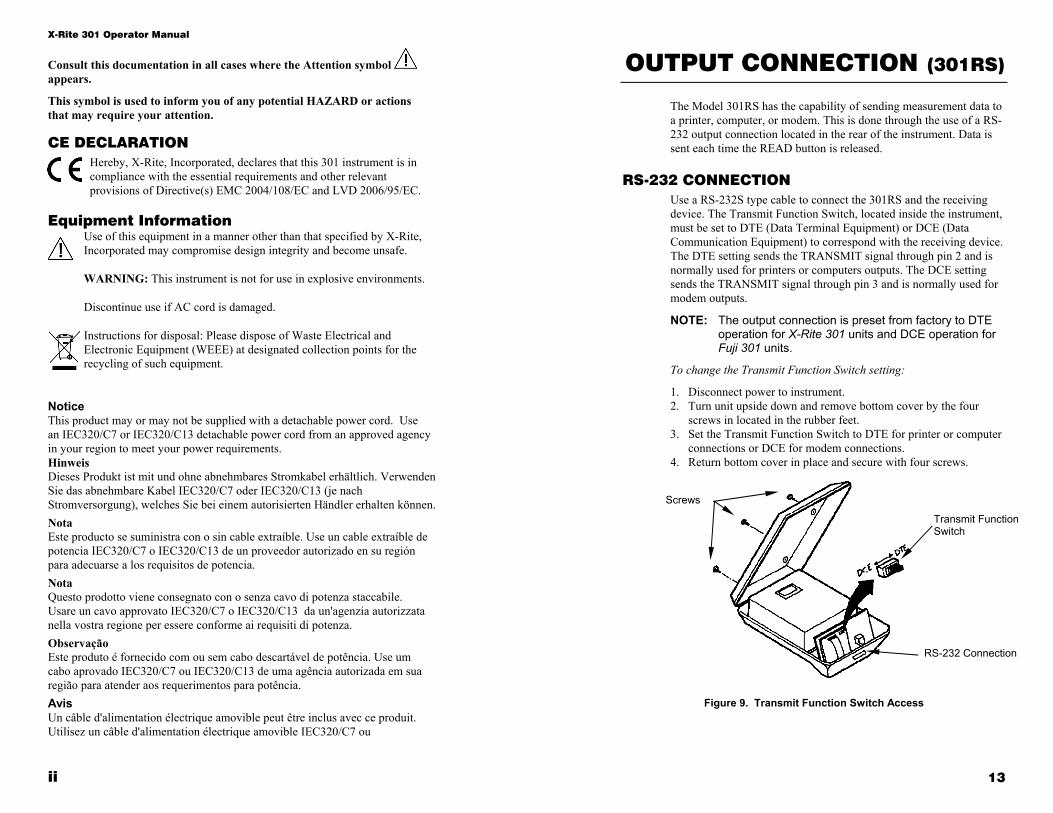
The Model 301RS has the capability of sending measurement data to a printer, computer, or modem. This is done through the use of a RS-232 output connection located in the rear of the instrument. Data is sent each time the READ button is released.
RS-232 CONNECTION Use a RS-232S type cable to connect the 301RS and the receiving device. The Transmit Function Switch, located inside the instrument, must be set to DTE (Data Terminal Equipment) or DCE (Data Communication Equipment) to correspond with the receiving device. The DTE setting sends the TRANSMIT signal through pin 2 and is normally used for printers or computers outputs. The DCE setting sends the TRANSMIT signal through pin 3 and is normally used for modem outputs.
NOTE: The output connection is preset from factory to DTE operation for X-Rite 301 units and DCE operation for Fuji 301 units.
To change the Transmit Function Switch setting:
1. Disconnect power to instrument. 2. Turn unit upside down and remove bottom cover by the four
screws in located in the rubber feet. 3. Set the Transmit Function Switch to DTE for printer or computer
connections or DCE for modem connections. 4. Return bottom cover in place and secure with four screws.
Figure 9. Transmit Function Switch Access
Screws
RS-232 Connection
Transmit Function Switch
12
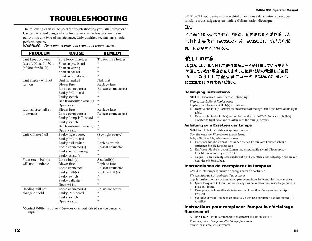
TROUBLESHOOTING The following chart is included for troubleshooting your 301 instrument. Use care to avoid danger of electrical shock when troubleshooting or performing any type of maintenance. Only qualified technicians should perform repairs. WARNING: DISCONNECT POWER BEFORE REPLACING PARTS.
PROBLEM CAUSE REMEDY
Unit keeps blowing fuses (500ma for 301) (400ma for 301X)
Fuse loose in holder Short in p.c. board Short in wiring Short in ballast Short in transformer
Tighten fuse holder * * * *
Unit display will not turn on
Unit not nulled Blown fuse Loose connector(s) Faulty P.C. board Faulty switch Bad transformer winding Open wiring
Null unit Replace fuse Re-seat connector(s) * * * *
Light source will not illuminate
Blown fuse Loose connector(s) Faulty Lamp P.C. board Faulty switch Bad transformer winding Open wiring
Replace fuse Re-seat connector(s) * * * *
Unit will not Null Faulty light source Faulty P.C. board Faulty null switch Loose connector(s) Faulty sensor wiring Faulty sensor(s)
(See light source) * Replace switch Re-seat connector * *
Fluorescent bulb(s) will not illuminate
Loose bulb(s) Blown fuse Loose connector Faulty bulb(s) Faulty switch Faulty ballast(s) Open wiring
Seat bulb(s) Replace fuse Re-seat connector Replace bulb(s) * * *
Reading will not change or hold
Loose connector(s) Faulty P.C. board Faulty switch Open wiring
Re-set connector * * *
*Contact X-Rite Instrument Services or an authorized service center for repair.
X-Rite 301 Operator Manual
iii
IEC320/C13 approuvé par une institution reconnue dans votre région pour satisfaire à vos exigences en matière d'alimentation électrique.
Relamping Instructions
NOTE: Disconnect Power Before Relamping Fluorescent Bulbs(s) Replacement Replace the Fluorescent Bulb(s) as Follows: 1. Remove the four (4) screws on the corners of the light table and remove the light
table. 2. Remove the faulty bulb(s) and replace with type F6T5/D fluorescent bulb(s). 3. Locate the light table and refasten with the four (4) screws.
Anleitung zum Ersetzen der Lampe N.B. Stromkabel muß dabei ausgezogen werden. Zum Ersetzen der Fluoreszenz-Leuchtbirne: Folgen Sie den folgenden Anweisungen: 1. Entfernen Sie die vier (4) Schrauben an den Ecken vom Leuchttisch und
entfernen Sie die Leuchtplatte. 2. Entfernen Sie die kaputten Birnen und ersetzen Sie sie mit Fluoreszenz-
Leuchtbirnen vom Typ F6T5/D. 3. Legen Sie die Leuchtplatte wieder auf den Leuchttisch und befestigen Sie sie mit
den vier (4) Schrauben.
Instrucciones de reemplazar la lampara AVISO: Interrumpa la fuente de energía antes de continuar El reemplazo de las bombillas fluorescentes Siga las instrucciones a continuación para reemplazar las bombillas fluorescentes: 1. Quite los quatro (4) tornillos de los ángulos de la mesa luminosa, luego quite la
mesa luminosa. 2. Reemplace las bombillas defectuosas con bombillas fluorescentes del tipo
F6T5/D. 3. Coloque la mesa luminosa en su sitio y asegúrela apretando con los quatro (4)
tornillos.
Instructions pour remplacer l’ampoule d’éclairage fluorescent
ATTENTION: Pour commencer, déconnecter le cordon secteur. Pour remplacer l’ampoule d’éclairage fluorescent Suivre les instructions suivantes:

X-Rite 301 Operator Manual
iv
1. Enlever les quatre (4) vis dans les coins de la table lumineux, et démonter la plaque translucide.
2. Enlever l’ampoule d’éclairage cassé et le remplacer avec un ampoule d’éclairage fluorescent du type F6T5/D.
3. Remplacer la plaque translucide et la retenir avec les quatre (4) vis.
Istruzioni per sostituire la lampada AVVISO: Interrompere l’energia prima di continuare La sostituzione delle lampade fluorescenti Eseguire l’istruzioni seguenti per sostituire le lampade fluorescenti: 1. Togliere le quattro (4) viti dei angoli del tavolo luminoso, quindi togliere il
tavolo luminoso. 2. Sostituire le lampade difettose con lampade fluorescenti del tipo F6T5/D. 3. Collocare il tavolo luminoso en suo posto y assicurarlo con le quattro (4) viti.
LIMITED WARRANTY X-Rite warrants this Product against defects in material and workmanship for a period of twelve (12) months from the date of shipment from X-Rite’s facility, unless mandatory law provides for longer periods. During such time, X-Rite will either replace or repair at its discretion defective parts free of charge. X-Rite’s warranties herein do not cover failure of warranted goods resulting from: (i) damage after shipment, accident, abuse, misuse, neglect, alteration or any other use not in accordance with X-Rite’s recommendations, accompanying documentation, published specifications, and standard industry practice; (ii) using the device in an operating environment outside the recommended specifications or failure to follow the maintenance procedures in X-Rite’s accompanying documentation or published specifications; (iii) repair or service by anyone other than X-Rite or its authorized representatives; (iv) the failure of the warranted goods caused by use of any parts or consumables not manufactured, distributed, or approved by X-Rite; (v) any attachments or modifications to the warranted goods that are not manufactured, distributed or approved by X-Rite. Consumable parts and Product cleaning are also not covered by the warranty. X-Rite‘s sole and exclusive obligation for breach of the above warranties shall be the repair or replacement of any part, without charge, which within the warranty period is proven to X-Rite‘s reasonable satisfaction to have been defective. Repairs or replacement by X-Rite shall not revive an otherwise expired warranty, nor shall the same extend the duration of a warranty. Customer shall be responsible for packaging and shipping the defective product to the service center designated by X-Rite. X-Rite shall pay for the return of the product to Customer if the shipment is to a location within the region in which the X-Rite service center is located. Customer shall be responsible for paying all shipping charges, duties, taxes, and any other charges for products returned to any other locations. Proof of purchase in the form of a bill of sale or receipted invoice which is evidence that the unit is within the Warranty period must be presented to obtain warranty service. Do not try to dismantle the Product. Unauthorized dismantling of the equipment will void all warranty
Maintenance
11
FACTORY REPAIR X-Rite recognizes the need to provide complete technical repair service to customers. X-Rite provides repair of any 301 submitted past warranty. The customer shall pay shipping costs and the instrument shall be submitted in its original shipping carton as a complete unaltered unit.
FUSE LOCATION
FUSE CARRIER

Maintenance
10
FUSE REPLACEMENT Replacement Fuse for 115VAC Instrument:
X-Rite P/N SE49-0050 (Time-delay 500ma-250V, 5mm x 20mm)
Replacement Fuse for 230VAC Instrument: X-Rite P/N SE49-0040 (Time-delay 400ma-250V, 5mm x 20mm)
To replace fuse:
1. Turn power off (O) and remove detachable line cord. 2. Insert small flat-blade screwdriver into left edge of fuse carrier and pry out. 3. Remove blown fuse from carrier clip and discard. 4. Insert replacement fuse in fuse clip. 5. Reinsert fuse carrier into fuse cavity. Make sure carrier is firmly seated. 6. Reinstall detachable line cord.
FLAT-BLADE SCREWDRIVER
POWER SWITCH
FUSE CARRIER
X-Rite 301 Operator Manual
v
claims. Contact the X-Rite Support or the nearest X-Rite Service Center, if you believe that the unit does not work anymore or does not work correctly. THESE WARRANTIES ARE GIVEN SOLELY TO BUYER AND ARE IN LIEU OF ALL OTHER WARRANTIES, EXPRESSED OR IMPLIED, INCLUDING BUT NOT LIMITED TO THE IMPLIED WARRANTIES OF MERCHANTABILITY, FITNESS FOR A PARTICULAR PURPOSE OR APPLICATION, AND NON-INFRINGEMENT. NO EMPLOYEE OR AGENT OF X-RITE, OTHER THAN AN OFFICER OF X-RITE, IS AUTHORIZED TO MAKE ANY WARRANTY IN ADDITION TO THE FOREGOING. IN NO EVENT WILL X-RITE BE LIABLE FOR ANY OF BUYER’S MANUFACTURING COSTS, OVERHEAD, LOST PROFITS, GOODWILL, OTHER EXPENSES OR ANY INDIRECT, SPECIAL, INCIDENTAL OR CONSEQUENTIAL DAMAGES BASED UPON BREACH OF ANY WARRANTY, BREACH OF CONTRACT, NEGLIGENCE, STRICT TORT, OR ANY OTHER LEGAL THEORY. IN ANY EVENT OF LIABILITY, X-RITE’S MAXIMUM LIABILITY HEREUNDER WILL NOT EXCEED THE PRICE OF THE GOODS OR SERVICES FURNISHED BY X-RITE GIVING RISE TO THE CLAIM.
Proprietary Notice The information contained in this manual is derived from patent and proprietary data from X-Rite, Incorporated. This manual has been prepared solely for the purpose of assisting operation and maintenance personnel in their use of the X-Rite 301 Instrument.
The contents of this manual are the property of X-Rite, Incorporated and are copyrighted. Any reproduction in whole or part is strictly prohibited. Publication of this information does not imply any rights to reproduce it or use it for any purpose other than installing, operating, or maintaining the equipment described herein.
This instrument is covered by the following U.S. and foreign patents: U.S. Patent #4,080,075 and other patents pending.
Copyright ©2015 by X-Rite, Incorporated.
“ALL RIGHTS RESERVED.”

X-Rite 301 Operator Manual
vi
TABLE OF CONTENTS
Relamping Instructions .................................................................. iii Table of Contents ............................................................................ vi List of Figures ................................................................................. vi Introduction .......................................................................................1
Specifications ...............................................................................1 Unpacking ....................................................................................3
Operating Instructions .....................................................................3 Power Application .......................................................................3 Aperture Replacement .................................................................3 Nulling (Zeroing) Procedure .......................................................4 Absolute Density Measurement ...................................................4 Density Comparison Measurement ..............................................4
Calibration .........................................................................................5 Calibration Frequency .................................................................5 Calibration Procedure ..................................................................5
Maintenance ......................................................................................7 Cleaning .......................................................................................7 Fluorescent Bulb Replacement ....................................................8 Reading Lamp Replacement ........................................................9 Fuse Replacement ......................................................................10 Factory Repair ...........................................................................11
Troubleshooting ..............................................................................12 Output Connection (model 301RS) ...............................................13
RS-232 Connection ....................................................................13 Data Instruction Format .............................................................14
LIST OF FIGURES Figure 1. Applying Power .................................................................2 Figure 2. Aperture Removal .............................................................3 Figure 3. Calibration .........................................................................6 Figure 4. Calibration Step Tablet ......................................................6 Figure 5. Cleaning Instrument Optics ...............................................7 Figure 6. Fluorescent Lamp Access ..................................................8 Figure 7. Lamp PC Board Access .....................................................9 Figure 8. Densitometer PC Board Access .......................................10 Figure 9. Transmit Function Switch Access ...................................13
Maintenance
9
READING LAMP REPLACEMENT (P/N 301-21) Replace the reading area lamp as follows:
1. Remove the unit bottom cover by removing the four (4) screws located in the rubber feet.
2. Remove the four (4) screws securing the Lamp P.C. board to the arm assembly at bottom of chassis.
3. Disconnect lamp connector and remove faulty Lamp P.C. board.
NOTE: Ensure lamp P.C. board bulb is clean. Use alcohol on a lint free cloth or cotton swab to remove smudges.
CAUTION: The bulb on Lamp P.C. board has been prealigned for optimum optical performance. Use care not to bend or reposition the bulb when cleaning or installing.
4 Connect the lamp connector to new Lamp P.C. board. 5. Secure Lamp P.C. board to arm assembly with four (4) screws.
6. Reinstall bottom cover and secure with four (4) screws.
Figure 7. Lamp PC Board Access
Screws
Screws
Lamp PC Board Assy
Lamp Connector
Maintenance
8
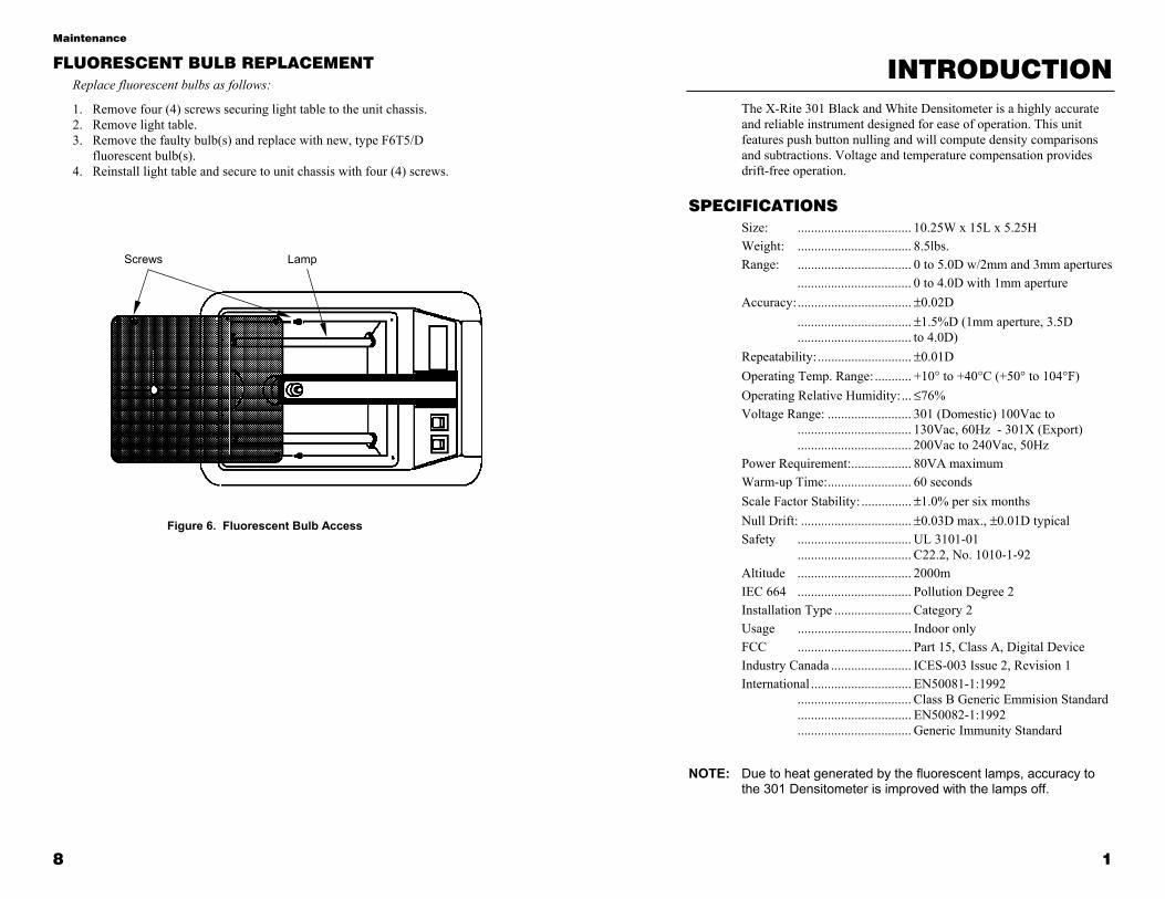
FLUORESCENT BULB REPLACEMENT Replace fluorescent bulbs as follows:
1. Remove four (4) screws securing light table to the unit chassis. 2. Remove light table. 3. Remove the faulty bulb(s) and replace with new, type F6T5/D
fluorescent bulb(s). 4. Reinstall light table and secure to unit chassis with four (4) screws.
Figure 6. Fluorescent Bulb Access
Screws Lamp
1
INTRODUCTION The X-Rite 301 Black and White Densitometer is a highly accurate and reliable instrument designed for ease of operation. This unit features push button nulling and will compute density comparisons and subtractions. Voltage and temperature compensation provides drift-free operation.
SPECIFICATIONS Size: .................................. 10.25W x 15L x 5.25H Weight: .................................. 8.5lbs. Range: .................................. 0 to 5.0D w/2mm and 3mm apertures .................................. 0 to 4.0D with 1mm aperture Accuracy: .................................. ±0.02D .................................. ±1.5%D (1mm aperture, 3.5D .................................. to 4.0D) Repeatability: ............................ ±0.01D Operating Temp. Range: ........... +10° to +40°C (+50° to 104°F) Operating Relative Humidity: ... ≤76% Voltage Range: ......................... 301 (Domestic) 100Vac to .................................. 130Vac, 60Hz - 301X (Export) .................................. 200Vac to 240Vac, 50Hz Power Requirement: .................. 80VA maximum Warm-up Time: ......................... 60 seconds Scale Factor Stability: ............... ±1.0% per six months Null Drift: ................................. ±0.03D max., ±0.01D typical Safety .................................. UL 3101-01 .................................. C22.2, No. 1010-1-92 Altitude .................................. 2000m IEC 664 .................................. Pollution Degree 2 Installation Type ....................... Category 2 Usage .................................. Indoor only FCC .................................. Part 15, Class A, Digital Device Industry Canada ........................ ICES-003 Issue 2, Revision 1 International .............................. EN50081-1:1992 .................................. Class B Generic Emmision Standard .................................. EN50082-1:1992 .................................. Generic Immunity Standard
NOTE: Due to heat generated by the fluorescent lamps, accuracy to the 301 Densitometer is improved with the lamps off.
Operating Instructions
2
UNPACKING Remove the instrument from shipping carton. Inspect for possible damage. If any damage is noted, contact the transportation company immediately. Do nothing more until the carrier’s agent has inspected the damage.
If damage is not evident, make sure the following items are included.
• X-Rite 301 Operation Manual (with Warranty Card) • 1mm, 2mm and 3mm apertures (inside back cover of manual) • Standard Reference Step Tablet (inside front cover of manual) • 301(X) Instrument
7
MAINTENANCE
The 301 Densitometer is completely covered by a one (1) year warranty and should be referred to the factory or authorized service center for repairs within the warranty period. Attempts to make repairs within the warranty period may void the warranty. If repairs are needed after the warranty period, only qualified technicians should perform such repairs.
Refer to the exploded view illustration of the 301 on page 16.
WARNING: DISCONNECT POWER BEFORE PERFORMING ANY MAINTENANCE.
CLEANING General cleaning of the 301 Densitometer should be done with mild a soap solution.
CAUTION: Do not use alcohol based solutions to clean light table.
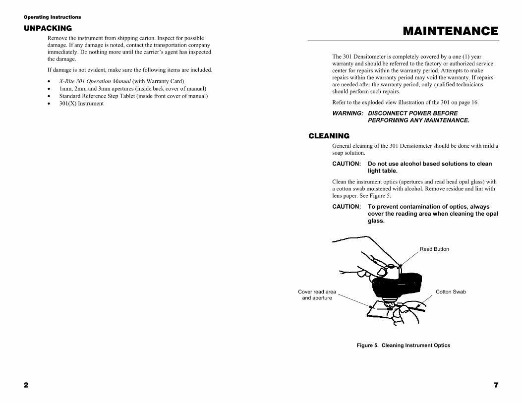
Clean the instrument optics (apertures and read head opal glass) with a cotton swab moistened with alcohol. Remove residue and lint with lens paper. See Figure 5.
CAUTION: To prevent contamination of optics, always cover the reading area when cleaning the opal glass.
Figure 5. Cleaning Instrument Optics
Cover read area and aperture
Read Button
Cotton Swab

Calibration
6
Figure 3. Calibration
Figure 4. Calibration Step Tablet
Calibration Point
CAL Density Value
“CAL” portion of step tablet centered on Target Window
Calibration Adjustment
Read Button
Operating Instructions
3
OPERATING INSTRUCTIONS
Operation of the X-Rite 301 is very simple. Procedures of the various modes of operation are provided in the following paragraphs. When operating the instrument, use these recommended common sense suggestions to protect yourself and your instrument:
• Avoid dangerous environments (e.g., don’t use instrument in damp, wet areas)
• Use proper electrical connections. • Ensure electric cord does not interfere with work. • Disconnect power before servicing.
POWER APPLICATION The 301(X) is designed to operate from a standard grounded line source. Always plug the instrument into a 3-wire receptacle.
1. Plug line cord into a 3-wire grounded outlet. 2. Turn on power switch.
APERTURE REPLACEMENT Remove the installed aperture by lifting the edge upward. Install a new or different aperture by inserting the aperture into the light source cavity, making sure that the aperture is fully seated and pressed flush against the cavity.
Figure 2. Aperture Removal
Read Button
Operating Instructions
4
NULLING (ZEROING) PROCEDURE Due to the electronic memory loss caused by power removal, null must be established each time power to the instrument is removed. Null remains very stable (±0.01D) as long as power remains on.
Null the instrument as follows:
1. Remove film from reading area. 2. Lower the reading head by pressing the read button until it deflects
totally and actuates the switch. 3. Momentarily push the null button. 4. Remove pressure on the read button to release the reading head.
NOTE: The read button is a read-hold activator. Compress the button with only as much pressure as necessary for total deflection.
ABSOLUTE DENSITY MEASUREMENT Measure absolute density as follows:
1. Null the instrument as previously described in Nulling (Zeroing) Procedure.
2. Center the film area directly over the bright green light spot under the reading head.
3. Lower the reading head by pressing the read button until it totally deflects and actuates the switch.
4. Allow the instrument reading to settle to a stable number. 5. Remove pressure on the read button to release the reading head.
NOTE: Always measure density with the film emulsion side up. When measuring density values above 2.50D, ensure that reading head light seal is completely on surface of the film being measured.
DENSITY COMPARISON MEASUREMENT Compare density readings as follows:
1. Place reference film over aperture. Press read button and momentarily press the null button.
2. Place the film to be compared over the aperture and measure density. • This measurement is the difference between the reference film
density and the compared film density. • A negative (–) display indicates a lower compared film density than
the reference film.
NOTE: When referencing with densities greater than 3.00D, press the null button longer to allow the instrument electronics to fully stabilize.
5
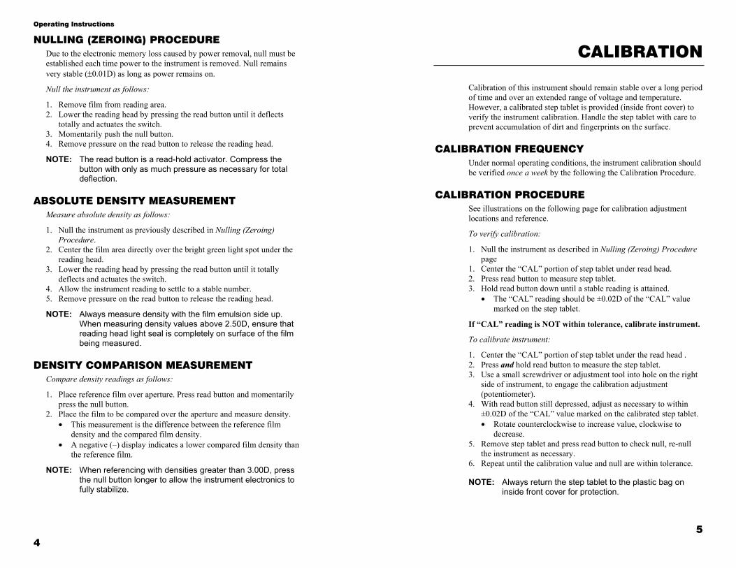
CALIBRATION
Calibration of this instrument should remain stable over a long period of time and over an extended range of voltage and temperature. However, a calibrated step tablet is provided (inside front cover) to verify the instrument calibration. Handle the step tablet with care to prevent accumulation of dirt and fingerprints on the surface.
CALIBRATION FREQUENCY Under normal operating conditions, the instrument calibration should be verified once a week by the following the Calibration Procedure.
CALIBRATION PROCEDURE See illustrations on the following page for calibration adjustment locations and reference.
To verify calibration:
1. Null the instrument as described in Nulling (Zeroing) Procedure page
1. Center the “CAL” portion of step tablet under read head. 2. Press read button to measure step tablet. 3. Hold read button down until a stable reading is attained.
• The “CAL” reading should be ±0.02D of the “CAL” value marked on the step tablet.
If “CAL” reading is NOT within tolerance, calibrate instrument.
To calibrate instrument:
1. Center the “CAL” portion of step tablet under the read head . 2. Press and hold read button to measure the step tablet. 3. Use a small screwdriver or adjustment tool into hole on the right
side of instrument, to engage the calibration adjustment (potentiometer).
4. With read button still depressed, adjust as necessary to within ±0.02D of the “CAL” value marked on the calibrated step tablet. • Rotate counterclockwise to increase value, clockwise to
decrease. 5. Remove step tablet and press read button to check null, re-null
the instrument as necessary. 6. Repeat until the calibration value and null are within tolerance.
NOTE: Always return the step tablet to the plastic bag on
inside front cover for protection.