pmwc integration memo 2015 1231 - apps.larimer.org file2 developed a recommended list of short-term...
TRANSCRIPT
1
Memo Date: January 15, 2016
Project: PMWC Voluntary Water System Transfer to the Town of Estes Park
To: Jeff Boles and Reuben Bergsten
From: Jennifer Stillman, P.E.
Subject: Evaluation of Integration Issues
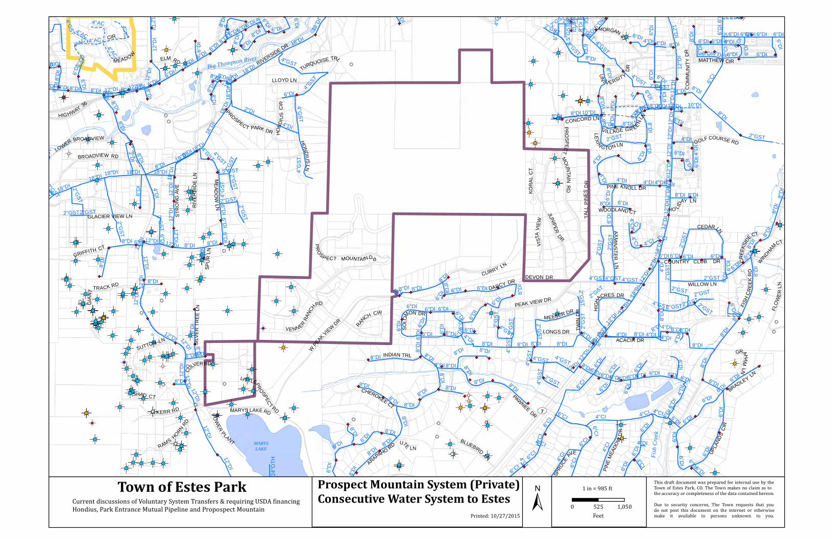
Introduction The Prospect Mountain Water Company (PMWC) owns a small water system (PWSID #CO0135621) that serves approximately 183 properties in three subdivisions including Lower Venner Ranch (also known as Ranch Circle Estates), Upper Venner Ranch and Koral Heights in the Estes Valley. In addition, the PMWC also provides water to a consecutive system called “Little Prospect Mountain”, which consists of approximately eight homes. In general, the PMWC water system consists of two booster pump stations, two active storage tanks, and 2”-6” galvanized steel distribution piping. The system has two pressure zones with Koral Heights and Lower Venner Ranch being on the lower pressure zone and Upper Venner Ranch and Little Prospect Mountain being on the upper pressure zone. The average and maximum day demands of the system (including both pressure zones) are 16,000 and 23,000 gallons per day, respectively. Attachment 1 contains a location map of the PMWC water system relative to the Town of Estes Park and other private water systems in the Estes Valley, a schematic of the PMWC water system service areas and primary infrastructure, and a hydraulic profile. Additional information about the PMWS water system can be found in the 2015 Master System Improvements Plan (FEI Engineers, April 2015).
The Town of Estes Park (Town) has been providing finished water to the PMWC as a consecutive system since 2012 via an interconnect to the Town’s water system. The PMWC filed for bankruptcy in the spring of 2015 and discussions have been underway to evaluate the possibility for the Town to operate the PMWC water system and to eventually accept a voluntary system transfer to the Town. In August 2015, the Town retained HDR to provide engineering assistance to evaluate the integration issues associated with taking over operation and ownership of the PMWC water system. The following objectives were accomplished during the engineering evaluation:
Inspected select components of the PMWC water system infrastructure and provided a condition assessment
Reviewed PMWC water quality compliance information and inspection reports from the Colorado Department of Public Health and Environment (CDPHE)
Coordinated with CDPHE to discuss potential impacts to the Town associated with the Town operating and taking ownership of the PMWC water system

2
Developed a recommended list of short-term and long-term improvement projects to the PMWC water system, including opinions of probably construction cost for the long-term projects
The purpose of this memo is to compile and summarize the results of the engineering evaluation. The memo is organized into three sections that will address the condition assessment, regulatory compliance and the PMWC water system needs.
Condition Assessment
HDR performed a general condition assessment on the PMWC water system infrastructure on Friday, June 12, 2015. Representatives from the Town, HDR, and the PMWC certified operator in responsible charge (ORC) attended the site visit. Five (5) primary System Areas were reviewed and are used to categorize the condition assessment observations outlined in the tabulation which follows. The System Areas include:
1. Booster Pump Station 1 (previously the Water Treatment Building prior to 2012) 2. Booster Pump Station 2 3. Tank 1 - 120,000 Gallons 4. Tank 2 - 30,000 Gallons 5. Tank 3 - 8,500 Gallons

3
SYSTEM AREA ITEM NUMBER
CONDITION OBSERVATION
Booster Pump Station 1
1 Booster Pump Station 1 was constructed around 1968. The building is constructed with CMU block and there are multiple locations where the grout has cracked in the past and has been resealed with grout. There is also a large bolt that extends across the width of the building presumably to provide additional structural support. The building should undergo a comprehensive structural evaluation to assess its integrity.

4
Booster Pump Station 1
2 The door frame is unfinished wood and the security of the door itself is questionable. The exposed wood on the outside of the building needs to be painted.
Booster Pump Station 1
3 There is a drainageway located on the side of the building. The operator reported that the building is subject to flooding during spring runoff with up to 6 inches of water on the floor inside the building.

5
Booster Pump Station 1
4 Gas odors were present in the vicinity of the propane tank located at the back of the building. The tank should be checked for leaks. Also, there is a large amount of debris behind the building that should be removed.
Booster Pump Station 1
5 The US Filter Memcor microfiltration membrane skid has been out of operation since 2012 when the PMWC transitioned from taking its raw water supply from the BOR tunnel to receiving treated water from the Town’s water system via an interconnect between the two systems. The PMWC operator reported the skid is rated for 50 gpm and runs well at 30 gpm. The operator also reported that Rainey Environmental offered to purchase the skid for $10,000 within the past year. Some of the PVC piping on the skid is cracked from freezing.

6
Booster Pump Station 1
6 The Town owns the water meter located inside the building. Downstream of the meter, there is a solenoid valve that is currently open and not wired for automatic operation. Booster Pump Station 1 can receive a wireless signal from Tank 1 (120,000 gallons) via the Airbits antenna and a repeater. However, this function is not currently hooked up. There is a bypass pipe installed around the solenoid valve.
Booster Pump Station 1
7 The inline booster pump is no longer routinely needed as the Town’s pressure is adequate to supply Booster Pump Station 2 and Tank 1 (in most instances). The pump suction and discharge piping has been installed in such a manner that access to the pump is difficult so it has been left in place. A spare pump is also available in the building. Both pumps are Goulds Model 45HB15013, 5 HP, 3600 rpm.

7
Booster Pump Station 1
8 There are three (3) large polyethylene tanks in the building. Two of the tanks are roughly 1,000-1,500 gallons and were previously used for chlorine contact time. The third tank is roughly 500 gallons and was previously used as a backwash/surge tank for the membrane system. Waste flows from the building are connected to the Upper Thompson Sanitation District collection system.
Booster Pump Station 1
9 The PMWC is currently feeding sodium hypochlorite to the treated water pipe inside the building to boost the chlorine residual. The feed pump is a Stenner Model SVP1 (5 gpd, 100 psi) and is sitting on top of a desk area. A spare LMI feed pump was sitting on the shelf above the Stenner pump. The operator reported that the chlorine is only boosted in the summer season. There is a static inline mixer installed in the pipeline for mixing.

8
Booster Pump Station 1
10 A Hach CL17 chlorine analyzer with an SC100 controller is installed inside the building. The PMWC operator reported that the analyzer did work properly when the membrane system was last online in 2012.
Booster Pump Station 1
11 Pump control panels show evidence of corrosion indicating that the building may not be properly ventilated.

9
Booster Pump Station 1
12 In general, there is a significant amount of debris inside the building that presents a safety hazard for operators and makes access to the process systems very difficult for routine operation and maintenance.
Booster Pump Station 2
13 Booster Pump Station 2 is a manhole located adjacent to the 30,000 gallon storage tank. A centrifugal pump (same type/model as Booster Pump Station 1) is installed inside the manhole, which pumps water from the lower pressure zone to the 8,500 gallon buried storage tank. The pump suction and discharge piping includes old fittings and couplings that are common to the mining industry and not standard for process systems. Access to the pump for routine maintenance is very restricted within the 5 foot diameter manhole. This pump is a single point of failure for the PMWC upper pressure zone since there is no redundant pump at this location. If the pump fails, the spare pump located at Booster Pump Station 1 will have to be transported to this site and installed. The pump turns on/off automatically based on a float switch located inside the 8,500 gallon tank. The control wiring runs above grade between the booster pump station and the tank, which leaves it exposed to damage from the elements or vandalism.

10
Tank 2 14 Tank 2 is a 30,000 gallon above grade steel tank that is no longer in service. The PMWC operator reported that the tank has significant leaks.
Tank 2 15 There is a wood box located on the side of the tank that houses some of the valving
and instrumentation for the tank.
11
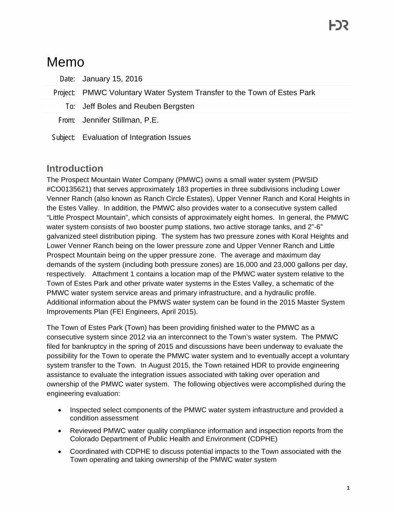
Tank 3 16 Tank 3 is an 8,500 buried steel tank. The PMWC operator reported that the tank was installed in the 1960’s, which means that it has reached its expected service life. Staff from the Town’s Water Dept. report sticking a rod in the tank many years ago and encountering a significant amount of sludge, but this has not been confirmed. The tank needs to be drained, cleaned, and inspected.
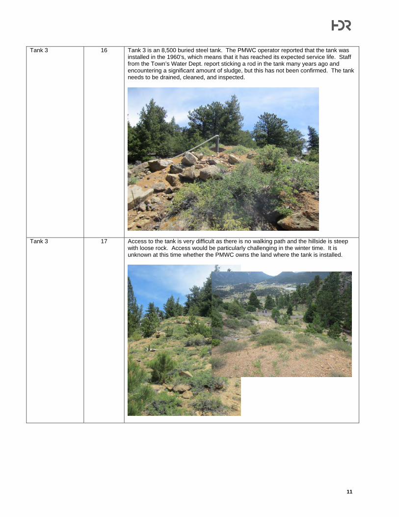
Tank 3 17 Access to the tank is very difficult as there is no walking path and the hillside is steep with loose rock. Access would be particularly challenging in the winter time. It is unknown at this time whether the PMWC owns the land where the tank is installed.

12
Tank 3 18 Despite the elevation of Tank 2, some of the Prospect Mountain homes still have their own booster pump systems.
Tank 3 19 The overflow for the tank discharges at a higher elevation than the top of the tank. A 2”
PVC overflow pipe has been routed overland, but the discharge point was not observed. The overflow discharge should be checked to see if there is potential for contamination to the tank. A drain pipe was not visible for the tank, but the PMWC operator reported that he believes a drain exists.

13
Tank 3 20 The tank has a small manway access. It appeared to be 14”-16” diameter. This limited size makes access to the tank very difficult and probably impossible for a dive inspection. The CDPHE will most likely implement new mandatory tank inspection requirements in the Spring of 2016. The new requirements include quarterly inspections every year and thorough inspections every 3-5 years. The tank is equipped with float controls, which automatically start/stop the pump in Booster Pump Station 2. However, there is no level monitoring or alarms provided. The control wire between Booster Pump Station 2 and the tank are routed overland (see Item 13) and through a drainage culvert under the access road.
Tank 1 21 Tank 1 is a 120,000 gallon buried concrete storage tank that was originally constructed
by the Town for the Town’s water system and then turned over to PMWC in 2006-2007. The tank was modified at that time to extend the piping to the back of the tank with diffusers, modify the baffling to improve tank circulation, and add a vent pipe. The tank was then brought online in 2008. (Frachetti was the engineer for this design.) The PMWC operator reported that there was not significant sediment in the bottom and no noticeable cracking in the concrete when the work was completed in 2006-2007. The tank is still due to be inspected. This could potentially be done using a dive type inspection.

14
Tank 1 22 Tank 1 is equipped with float controls for automatic filling from Booster Pump Station 1, however, the system is not currently hooked up. There is wireless communication capability between the tank and Booster Pump Station 1 via the Airbits antenna and a repeater. The tank is manually filled by the PMWC operator by throttling a supply valve inside Booster Pump Station 1. The PMWC operator reported that he manually adds bleach to this tank. There was evidence of campfires on top of this tank indicating that the public does use this space.
Tank 1 23 The tank has a single access hatch with a 6” vent located adjacent to the hatch. The inlet and valve manhole is located on the hillside below the hatch. The 2014 CDPHE Sanitary Survey cited a significant deficiency for this tank because the tank overflow is buried, which presents a potential source of contamination to the tank. The PMWC operator reported that the overflow is buried by approximately 2 feet and might be constructed of 6” PVC. (Note, since the time of this condition assessment, it has been reported that the buried overflow has been addressed.)

15
Regulatory Compliance Although the PMWC is regulated by the Colorado Public Utilities Commission (PUC), it is also bound to the drinking water regulatory requirements of the CDPHE. The latter primarily involves distribution system water quality requirements, system monitoring requirements and integration issues with respect to the Town potentially operating and taking ownership of the PMWC water system. These topics will be discussed in this section.
Distribution System Water Quality As previously mentioned, the PMWC has been taking treated water from the Town since 2012. The PMWC is required to monitor the water quality in its distribution system for regulatory compliance. The monitoring includes pathogens (total coliform), chlorine residual, disinfection byproducts, and lead and copper. Table 1 summarizes PMWC’s Monitoring Plan for 2015.
Table 1. 2015 PMWC Monitoring Schedule Distribution System Sample Schedule
Parameter Sample Schedule Collection period Notes Total Coliform Bacteria (TCR)
1 sample per month Jan. 2015 – Dec. 2015
Free Chlorine 1 sample per month Jan. 2015 – Dec. 2015 Take every time TCR is taken
TTHM 1 per sample point
per year Aug 2015
Dual sample with HAA5
HAA5 1 per sample point
per year Aug 2015
Dual sample with HAA5
Lead 10 samples every 6
months Jan. 2015 – Dec. 2015
Compliance check in 1st 6 months and 2nd 6 months
Copper 10 samples every 6
months Jan. 2015 – Dec. 2015
Compliance check in 1st 6 months and 2nd 6 months
Compliance Schedules Activity Name Activity Due Date Activity Completion
Date Notes
Submit CCR Report to State June 30, 2015 Not Completed Submit Certificate of Delivery
June 30, 2015 Not Completed
Facility Specific Levels Analyte Name Level Level Type Notes
Free Chlorine Detectable* Minimum Free Chlorine 4.0 mg/L Maximum
*Minimum free chlorine residual has since been revised to 0.2 mg/L.
The only distribution system water quality sampling data that was available for review was the 2014 Consumer Confidence Report (CCR), which is summarized in Table 2.

16
Table 2. 2014 Distribution System Water Quality as Reported in the 2015 PMWC Consumer Confidence Report
Parameter 2014 Sample
Results Regulatory Limit
Meets Requirements
Copper (ppm) 0.47 1.3 Yes Lead (ppb) 12-28 15 No Haloacetic Acids (HAA5) (ppb)
23.4 60 Yes
Total Trihalomethanes (TTHMs) (ppb)
71.5 80 Yes
Gross Alpha (pCi/L) 1.5 15 Yes Antimony (ppb) 2 6 Yes Barium (ppm) 0 2 Yes Nitrate (ppm) 0.03 10 Yes Total Dissolved Solids (ppm) 38 500 Yes
As shown in Table 2, the PMWC met all of the compliance requirements for distribution system water quality with the exception of lead. Compliance for lead will be discussed further in the next section. The other notable observation from Table 1 is that the total trihalomethanes (TTHMs) approached the regulatory limit of 80 ppb. This is an indication of long residence times in the PMWC water system. The CDPHE indicated that the PMWC had no other recorded violations for coliforms, DBPs or chlorine residuals although the system did fail to monitor for these parameters on a number of occasions.
Lead Compliance Lead concentrations in drinking water are regulated under the Environmental Protection Agency’s (EPA’s) Lead and Copper Rule (LCR), which was first published in 1991 and has undergone subsequent revisions. The regulatory action limit for lead is 15 parts per billion (ppb), which cannot be exceeded in more than 10 percent of the customer taps sampled. When the action limit is exceeded, the utility must notify the consumers and undertake provisions to control corrosion in the distribution system.
The PMWC system exceeded the lead action level in 2010, 2011, 2012, and 2014. The most recent violation occurred during June of 2014 when two of the sample locations had measured lead concentrations of 28 ppb. The last two rounds of samples, collected in December 2014 and June 2015, were in compliance. Starting in 2016, the CDPHE intends to place the PMWC on a reduced sampling schedule which is once per year for the next three years. However, if another lead violation takes place, then the PMWC will return to the more stringent sampling schedule of twice per year.
Elevated lead concentrations are typically caused by corrosion of distribution system piping and household plumbing. The Town currently feeds a corrosion inhibitor at both of their drinking water treatment plants to control corrosion in their distribution system. When the corrosion inhibitor is first started, a high dose must be fed to establish a base coating inside the distribution piping to protect from corrosion. After the base coating is established inside the piping (typically after 1 year), a smaller maintenance dose of corrosion inhibitor may be used.

17
Although the PMWC water system has been receiving Town water since 2012, it is likely that this base coating has not been established in the PMWC distribution piping. The CDPHE has indicated that it would be acceptable for the Town to install a new corrosion inhibitor feed system at the interconnect between the PMWC water system and the Town’s water system. Installation of the feed system would require formal engineering approval by the CDPHE. This should address the majority of the lead issues in the PMWC water system, however, additional investigation into lead “hot spots” will be required.
The next revision to the LCR is expected to be proposed in 2017 and final in 2018-2019. Although the specifics of the future rule are not known, the intent is to resolve the complex issued related to replacing lead service lines. Currently, the utility may be required to replace lead service lines in the distribution system if they are owned by the utility and not by the individual homeowner.
Sanitary Surveys The CDPHE conducts routine inspections of all public water systems within the State. These inspections are referred to as Sanitary Surveys and the PMWC water system was last inspected in November 2014. A complete copy of the inspection report is provided in Attachment 2 and the results are summarized below.
Significant Deficiency
The overflow for the 120,000 gallon buried concrete tank (Tank 1) was buried, which presents a risk for contamination to the system. (Note, it has been reported that this issue has been resolved.)
Violations
The PMWC does not have documented coliform and chlorine monitoring data for the past 5 years.
The PMWC does not have a Monitoring Plan (Note, a Monitoring Plan has since been generated by the PMWC as summarized in Table 1.)
Recommendations
Storage tank level monitoring capability and alarms should be installed.
The storage tanks should be cleaned and inspected, particularly the 8,500 gallon steel buried tank (Tank 2).
An Emergency Response Plan and O&M plan should be established.
In general, significant deficiencies require that action be taken by the utility to correct the problem. Therefore, the overflow needs to be uncovered and properly equipped (air gap, screens, etc.) in order to not incur further enforcement by the CDPHE. Also, it was noted in the Sanitary Survey that the CDPHE will establish a new regulation for storage tank inspections in

18
2016. The requirement will most likely be that all system storage tanks be routinely inspected at least quarterly and receive a comprehensive inspection every five years.
Integration Issues HDR spoke with representatives of the CDPHE to discuss the compliance issues related to the integration of the PMWC water system into the Town’s water system. The potential for the Town to operate and take ownership of the system were both discussed. Copies of the telephone records are included in Attachment 3. The key points of operation and ownership are:
Town Take Over Operation of PMWC Water System
The Town can take over operation of the PMWC water system while still maintaining its status as a consecutive water system.
Legal enforcement of regulatory compliance only applies to the owner of the system and not the operator of the system.
The operator of the system is still bound by the ethics of Regulation 100 (CDPHE Water and Wastewater Facility Operators Certification Requirements, Regulation 100, 5 CCR 1003-2).
The only documentation that needs to be completed for the Town to take over operation is an update to the PMWC’s “Monitoring Plan” to document that the Town is taking over as the ORC (operator in responsible charge).
Although not directly discussed with CDPHE, it is likely that the CDPHE would allow the Town to operate the PMWC water system as a consecutive system, but still combine the PMWC’s monitoring documentation into the Town’s monitoring documentation. This would include the CCR and the Monitoring Plan. In short, the Town should be able to prepare a common CCR and Monitoring Plan that would include the information for both the Town’s system and the PMWC system.
Town Take Over Ownership of PMWC Water System
The Town should be able to take ownership of the PMWC water system while still maintaining its status as a consecutive water system. However, this will require formal approval by the CDPHE, since it may never have been done before and therefore would set a new precedent. The process to obtain the formal approval will involve the CDPHE’s legal council and could take a significant amount of time (up to 1 year estimated).
If the PMWC water system cannot be maintained as a separate, consecutive system, then any regulatory compliance issues associated with the PMWC will be applicable to the Town’s water system. This is significant with respect to the lead compliance issue as the entire Town’s water system could become out of compliance for lead, which would trigger the public notification process and increased sampling throughout the Town’s water system for a number of years.

19
PMWC System Needs
Based on the findings from the condition assessment and the regulatory compliance review and discussions with the Town’s water department staff, a list of system needs was developed. The list is divided into short-term and long-term needs, and is tailored to facilitate the Town taking over operation of the system and eventually taking ownership of the system. The list was presented at a public meeting to the PMWC customers on October 9, 2015 and is summarized below.
Short-term Address lead in distribution system
Inspect the 8,500 gallon buried steel tank (Tank 3)
Install remote system monitoring capability
Replace Booster Pump Station 2
Perform leak detection survey
Long-term Replace the 8,500 gallon buried steel tank (Tank 3)
The list of needs presented above is intended to supplement the recommended improvements that were included in the 2015 Master System Improvements Plan (FEI Engineers, April 2015). The primary focus of that plan was on reducing water loss and thus it emphasized the replacement of meters and distribution piping, which will also be needed in the long-term.
Cost Estimates At the Town’s request, opinions of probable costs were developed for two of the improvement projects listed above, replacement of Booster Pump Station 2 and replacement of the 8,500 gallon buried steel tank (Tank 3). Booster Pump Station 2 should be replaced because it presents a single point of failure for the upper pressure zone of the PMWC water system (only one pump is installed). Furthermore, access to the pump is very challenging if the pump needs to be maintained or replaced. Tank 3 should be replaced because it is past its useful service life and the tank cannot be readily maintained. The urgency of the Tank 3 replacement will be dependent on the results of the inspection/cleaning that is conducted in the short-term. In addition, prior to replacing the tank, the Town should perform a hydraulic study to evaluate the tank size and location with respect to system storage, fire flow requirements, and future integration with the Town’s water system.
The cost estimates for the Booster Pump Station 2 and Tank 3 replacements include construction costs, contractor’s markups, contingency, escalation to 2017, and engineering fees. The estimated total project costs for the replacement of Booster Pump Station 2 and Tank 3 are $336,000 and $239,000, respectively. The cost estimates represent a planning level estimate (+30%/-50%). Exhibits 1 and 2 provide brief project descriptions for both projects and the detailed cost estimates.
20
Operation Hours Estimate The estimated time required by the Town to operate the PMWC water system was developed based on knowledge of the current water system and input from the Town’s water department staff. The estimate is broken down into three categories including compliance sampling and activities, initial start-up operations and general operations. Table 3 summarizes the estimated hours of operation for the PMWC water system by the Town. The total estimated time during the first year of operation is 95 hours per month. Following the initial year of operation, the estimated time drops to 72 hours per month.
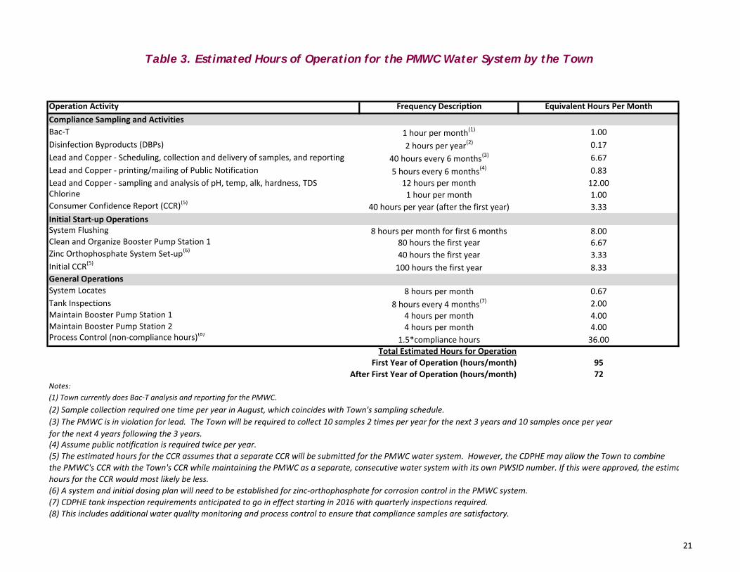
Table 3. Estimated Hours of Operation for the PMWC Water System by the Town
Operation Activity Frequency Description Equivalent Hours Per MonthCompliance Sampling and ActivitiesBac‐T 1 hour per month(1) 1.00Disinfection Byproducts (DBPs) 2 hours per year(2) 0.17Lead and Copper ‐ Scheduling, collection and delivery of samples, and reporting 40 hours every 6 months(3) 6.67Lead and Copper ‐ printing/mailing of Public Notification 5 hours every 6 months(4) 0.83Lead and Copper ‐ sampling and analysis of pH, temp, alk, hardness, TDS 12 hours per month 12.00Chlorine 1 hour per month 1.00Consumer Confidence Report (CCR)(5) 40 hours per year (after the first year) 3.33Initial Start‐up OperationsSystem Flushing 8 hours per month for first 6 months 8.00Clean and Organize Booster Pump Station 1 80 hours the first year 6.67Zinc Orthophosphate System Set‐up(6) 40 hours the first year 3.33Initial CCR(5) 100 hours the first year 8.33General OperationsSystem Locates 8 hours per month 0.67Tank Inspections 8 hours every 4 months(7) 2.00Maintain Booster Pump Station 1 4 hours per month 4.00Maintain Booster Pump Station 2 4 hours per month 4.00Process Control (non‐compliance hours)(8) 1.5*compliance hours 36.00
Total Estimated Hours for OperationFirst Year of Operation (hours/month) 95
After First Year of Operation (hours/month) 72Notes:(1) Town currently does Bac‐T analysis and reporting for the PMWC.(2) Sample collection required one time per year in August, which coincides with Town's sampling schedule.(3) The PMWC is in violation for lead. The Town will be required to collect 10 samples 2 times per year for the next 3 years and 10 samples once per yearfor the next 4 years following the 3 years.(4) Assume public notification is required twice per year.(5) The estimated hours for the CCR assumes that a separate CCR will be submitted for the PMWC water system. However, the CDPHE may allow the Town to combinethe PMWC's CCR with the Town's CCR while maintaining the PMWC as a separate, consecutive water system with its own PWSID number. If this were approved, the estimahours for the CCR would most likely be less.(6) A system and initial dosing plan will need to be established for zinc‐orthophosphate for corrosion control in the PMWC system.(7) CDPHE tank inspection requirements anticipated to go in effect starting in 2016 with quarterly inspections required.(8) This includes additional water quality monitoring and process control to ensure that compliance samples are satisfactory.
21
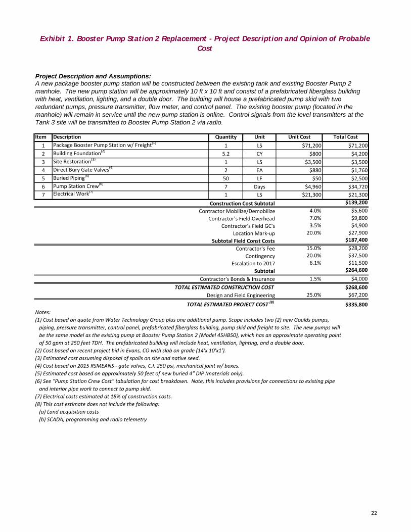
Exhibit 1. Booster Pump Station 2 Replacement - Project Description and Opinion of Probable Cost
Item Description Quantity Unit Unit Cost Total Cost1 Package Booster Pump Station w/ Freight(1) 1 LS $71,200 $71,2002 Building Foundation(2) 5.2 CY $800 $4,2003 Site Restoration(3) 1 LS $3,500 $3,5004 Direct Bury Gate Valves(4) 2 EA $880 $1,7605 Buried Piping(5) 50 LF $50 $2,5006 Pump Station Crew(6) 7 Days $4,960 $34,7207 Electrical Work(7) 1 LS $21,300 $21,300
Construction Cost Subtotal $139,200Contractor Mobilize/Demobilize 4.0% $5,600
Contractor's Field Overhead 7.0% $9,800Contractor's Field GC's 3.5% $4,900
Location Mark‐up 20.0% $27,900Subtotal Field Const Costs $187,400
Contractor's Fee 15.0% $28,200Contingency 20.0% $37,500
Escalation to 2017 6.1% $11,500Subtotal $264,600
Contractor's Bonds & Insurance 1.5% $4,000TOTAL ESTIMATED CONSTRUCTION COST $268,600
Design and Field Engineering 25.0% $67,200
TOTAL ESTIMATED PROJECT COST (8) $335,800Notes:(1) Cost based on quote from Water Technology Group plus one additional pump. Scope includes two (2) new Goulds pumps, piping, pressure transmitter, control panel, prefabricated fiberglass building, pump skid and freight to site. The new pumps willbe the same model as the existing pump at Booster Pump Station 2 (Model 45HB50), which has an approximate operating pointof 50 gpm at 250 feet TDH. The prefabricated building will include heat, ventilation, lighting, and a double door.
(2) Cost based on recent project bid in Evans, CO with slab on grade (14'x 10'x1').(3) Estimated cost assuming disposal of spoils on site and native seed.(4) Cost based on 2015 RSMEANS ‐ gate valves, C.I. 250 psi, mechanical joint w/ boxes.(5) Estimated cost based on approximately 50 feet of new buried 4" DIP (materials only).(6) See "Pump Station Crew Cost" tabulation for cost breakdown. Note, this includes provisions for connections to existing pipeand interior pipe work to connect to pump skid.
(7) Electrical costs estimated at 18% of construction costs.(8) This cost estimate does not include the following:(a) Land acquisition costs(b) SCADA, programming and radio telemetry
A new package booster pump station will be constructed between the existing tank and existing Booster Pump 2 manhole. The new pump station will be approximately 10 ft x 10 ft and consist of a prefabricated fiberglass building with heat, ventilation, lighting, and a double door. The building will house a prefabricated pump skid with two redundant pumps, pressure transmitter, flow meter, and control panel. The existing booster pump (located in the manhole) will remain in service until the new pump station is online. Control signals from the level transmitters at the Tank 3 site will be transmitted to Booster Pump Station 2 via radio.
Project Description and Assumptions:
22

Exhibit 2. Tank 3 Replacement - Project Description and Opinion of Probable Cost
Item Description Quantity Unit Unit Cost Total Cost1 Two New Buried Fiberglass Tanks (4,218 gallons each)(1) 1 LS $31,100 $31,1002 Disposal of Existing 8,500 Gallon Steel Tank(2) 1 LS $2,500 $2,5003 Imported Bedding for New Tanks(3) 270 CY $33 $8,7754 Site Restoration(4) 1 LS $3,500 $3,5005 Level Transmitters(5) 2 EA $1,500 $3,0006 Direct Bury Gate Valves(6) 2 EA $880 $1,7607 Disinfect Tank and Pipe(7) 1 LS $1,000 $1,0008 Tank Crew Cost(8) 7 Days $5,559 $38,9109 Electrical(9) 1 LS $8,300 $8,300
Construction Cost Subtotal $98,900Contractor Mobilize/Demobilize 4.0% $4,000
Contractor's Field Overhead 7.0% $7,000Contractor's Field GC's 3.5% $3,500
Location Mark‐up 20.0% $19,800Subtotal Field Const Costs $133,200
Contractor's Fee 15.0% $20,000Contingency 20.0% $26,700
Escalation to 2017 6.1% $8,200Subtotal $188,100
Contractor's Bonds & Insurance 1.5% $2,900TOTAL ESTIMATED CONSTRUCTION COST $191,000
Design and Field Engineering 25.0% $47,800
TOTAL ESTIMATED PROJECT COST (10) $238,800Notes:(1) Cost based on quote from Xerxes (material only). Does not include tank hold down components.(2) Estimated cost to haul and dispose of existing steel tank. (3) Cost based on 2015 RSMEANS ‐ crushed or screened gravel (material only) plus an $80/hr hauling cost.(4) Estimated cost assuming disposal of spoils on site and native seed.(5) Estimated cost for transmitter (material only).(6) Cost based on 2015 RSMEANS ‐ gate valves, C.I. 250 psi, mechanical joint w/ boxes (material only).(7) Estimated cost assuming disposal of dechlorinated disinfection water on site.(8) See "Tank Crew Cost" tabulation for cost breakdown. Note, this includes provisions for rock excavation and connections to existing pipe. The duration shown does not represent actual project duration, but is intended to account for average time of equipment spent on site balanced by labor time spent at the site.
(9) Electrical costs estimated at 18% of construction costs.(10) This cost estimate does not include the following:(a) Land acquisition costs(b) SCADA, programming and radio telemetry
The existing 8,500 gallon buried steel tank will be replaced with two (2) new buried fiberglass tanks with a total storage capacity of approximately 8,500 gallons. The new tanks will be installed adjacent to, and at the same location as the existing steel tank to minimize rock excavation costs. The work will be phased such that one of the new fiberglass tanks will be put into service prior to removing the existing steel tank from service. Each of the new tanks will be equipped with an ultrasonic level transmitter. Control signals from the level transmitters will be transmitted to Booster Pump Station 2 via radio.
Project Description and Assumptions:
23

Attachment 1
PMWC Water System Maps and Figures

G!.
G!.
G!.
G!.G!.
G!.
G!.
G!.G!.G!.
G!.
G!.
G!.G!.
G!.
G!.
G!.
G!.
G!.G!.G!.G!.
G!.
G!.
G!.
G!.
G!.
G!.
G!.
G!.
G!.G!.
G!.
G!.G!.G!.G!.
G!.
G!.
G!.G!.
G!.
G!.
G!.
G!.
G!.
G!.
G!.G!.
G!.
G!.
G!.
G!.
G!.G!.G!.
G!.G!.
G!.G!.
G!.
G!.
G!.
G!.
G!.
G!.
G!.
G!.
G!.G!.
G!.
G!.G!. G!.
G!.
G!.
G!.
G!.
G!.
G!.
G!.
G!.
G!. G!. G!.
G!.
G!.G!.
G!.
G!.
G!.G!.
G!.
G!.
G!.
G!.
G!.
G!.
G!.
G!.
G!.G!.
G!.G!.G!. G!. G!. G!. G!.
G!.
G!.
G!.G!.
G!.
G!.
G!.
G!.
G!.G!.
G!.
G!.
G!.
G!.
G!.
G!.
G!.
G!. G!.
G!.G!.
G!.G!.
G!.G!.
G!.
G!.
G!. G!. G!.
G!.G!.
G!.G!.
G!.
G!. G!.
G!.
G!.
G!.
G!.G!.
G!.G!.
G!.G!.
G!.
G!.
G!.
G!.
G!.
G!.
G!.G!.
G!.
G!.
G!. G!.
G!.
G!.
G!.G!.
G!.
G!.G!.
G!. G!.
G!.G!.
G!.
G!.
G!.
G!.
G!.G!.
G!.
G!.
G!.
G!.
G!.
G!.
G!.G!. G!. G!.
G!.G!.
G!.
G!.
G!.G!.
G!.
G!.G!.
G!.
G!.
G!.
G!.G!.
G!.
G!.
G!.
G!.
G!.
G!.
G!.G!.
G!.
G!.
G!.
G!. G!.G!. G!.
G!.
G!.
G!.
G!.
G!.
G!.
G!.
G!.
G!.
G!.G!.
G!.
G!.G!.G!.G!.
G!.
G!. G!. G!.
G!.
G!.G!.G!.
G!.
G!.G!.
G!.
G!.
G!. G!.G!.
G!.
G!. G!.
G!.
G!.G!.G!.
G!.
G!.
G!.
G!.
G!.
G!.
G!. G!.
G!.
G!.G!.G!.
G!.
G!.
G!.
G!.
G!.
G!.
G!.G!.
G!.
G!.G!.
G!.
G!.
G!.
G!.
G!.
G!.
G!.G!.
G!.
G!.
G!.
G!.
G!.
G!.
G!.
G!.
G!.
G!.
G!.
G!.
G!.
G!.
G!.
G!.
G!.
G!.
G!.
G!.
G!.
G!.
G!.
G!.
G!.
G!.
G!.
G!.
G!.
G!.
G!.G!.
G!.
G!.
G!. G!.G!.
G!.
G!.
G!.
G!.
G!.
G!.G!.
G!.
G!.
G!.
G!.
G!.G!.
G!.
G!.
G!.
G!.
G!.
G!.
G!.
G!.
G!.
G!.
G!.
G!.
G!. G!.
G!.G!.
G!.G!.G!.
G!.
G!.G!.G!.
G!. G!.
G!.G!.
G!.G!.G!.
G!.
G!.
G!.
G!.G!.
G!. G!.
G!.
G!.G!.
G!. G!.
G!.
G!.
G!.
G!.
G!.
G!.
G!.
G!.
G!.G!.
G!.
G!.
G!.
G!.
G!.
G!.
G!.
G!.
G!.
G!.
G!.
G!.
G!.
G!. G!.
G!.
G!.
G!.
G!.
G!.
G!.
G!.
G!.
G!.
G!.
G!. G!.
G!.
G!.
G!.
G!.
G!.
G!.
G!.G!.
G!.
G!.G!.
G!.
G!.
G!.G!.
G!.
G!.
G!.
G!.
G!.
MARYS
LAK
ER
D
CUMULUS DR
CONCORD LN
RIVERSIDE DR
GR
EY
FOX
DR
GRAVES AVE
NIMBUS DR
UPPER HIGH DR
ROCKWO
OD
LN
HIGH DR
M
ORGANS T
FIS
HC
REE
KR
D
RAMS HORN
RD
SCOTT AVE
KERR RD
4THS
T
W ELKHORN AVE
WIN
DCLIFFDR
LAU
RE
LL
N
PR
OS
PE
CT
MO
UN
TAIN
RD
FISHC
RE
EK
WA
Y
N SAINT VRAIN AVE
NOBL
ELN
EAGLECLIFF
RD
DEV
ON DR
SUTT
ON LN
CO
MM
U
NITY
DR
LAKESHO RE
DR
ZE
RM
AT
TTRL
WPEAK
VIEW
DR
MINERA L RD
BIR
CH
AV
E
RAN
GE
VIEW RD
HIGH ST
BA
KER
DR
UPPERBROADVIEW
MANFORD AVE
RA
INBO
WD
RJOHNSEN LN
PEAK VIEW DR
BRODIE AVE
PO
WE
RPLANT
BROOK DR
HIGHWAY 36
SPR
UCE
AV
E
PINEWOODL N
HIL
LR
D
BAILE
YLN
CLIFF RD
HO
ND
IUS
LN
GRIFFITH CT
3RD
ST
TYROLE
RN
EL N
CHEROK
EE
DR
EL
M A
VE
KOR
AL C
T
TWIN
DR
MALL RD
BRADLEY LN
AX
MIN
STE
RLN
SPRING ST
WAPITI CIR
1ST
ST
CIR
CLE D R
5TH S
T
ACAC IADR
LONGS
TRL
COLEMAN RD
TRAILBLA
ZE
R
W AY
AS
PE
ND
R
BRO
ADVIEW RD
AS
PE
NLN
LOT
T S
T
JUNI PE
RL N
2ND
ST
RAMSHORN DR
WILDLIFE LN
DUNRAVEN ST
DO
RSE Y DR
CARING LN
SPIRITLN
INDIAN TRLS
AN
BO
RN
DR
SOLOM
O
NDR
KALEY COT TAGE
RD
W
OUR A Y
D
R
WI
L LOW LN DA
ND
IEW
AY
PIN
EM
EA
DO
WD
R
UTEC
T
JACO
BRD
COLU MBINE
DR
EA
GLE
CLIFF
DR
E
RIV
ER
SID
ED
R
LOWER BROADVIEW
AV
AL
ON
DR
MILLS DR
HEIN
Z PK
WY
CO
URTNEY LN
CRAGS DR
EL
M R
D
CHIEFS HEAD RD
HIG
HW
AY66
RO
CKR
IDG
ER
D
KIOWA
TRL
JU
NIP
ER
DR
U P LAN
DS
CIR
ARA
PAH
O
RD
LARKSPUR
AVE
CURRY
LN
TUNNEL RD
TUN
NE
LR
D
ST
RO
NG
AV
E ME
AD
OW
LN
PI N
E KNOLL DR
STANLEY AVE
MORAINE AVE
LE
X INGTON
LN
AS
PE
NA
VE
M ES
A DR
W
IND
RIV
ER
TRL
KIOWA DR
JUNGFR
AU
TR
L
PONDEROSA AVE
BEAR LAKE RD
BEA
RLA
KE
RD
LO
NGS DR
LON
GV
IEW
DR
TAN
AG
ER
RD
LO
N G HOUSE
WA
Y
GIA
NTTRACK RD
BIG HORN TR
L
UTE LNCLIFF LN
TE
RR
AC
ELN
HIG
HW
AY
7
FL O
WE
R
LN
W
INDHAM CT
HON
DIU
S CIR
SA
INT
MO
RITZ
TRL
WILD
WO
OD
DR
LL
OYD LN
SU
NN
YM
EAD
LN
RANCH
CIR
ME
AD
OW
CIR
DE
K
KE RC
IR
CEDAR LN
STA
N
L EY CIRCLE
DR
Aspen Brook
Buck Creek
Fall River
East Fork Fish CreekWind River
Glacier Creek
Aspen Brook
Fish Creek
Fish C
reek
Beaver Brook
Big Thompson River
Big Thompson River
LAKEESTES
MARYSLAKE
UV7
UV66
£¤36
£¤36
£¤36
This draft document was prepared for internal use by theTown of Estes Park, CO. The Town makes no claim as to the accuracy or completeness of the data contained hereon.Due to security concerns, The Town requests that youdo not post this document on the internet or otherwisemake it available to persons unknown to you.
0 1,100 2,200Feet
1 in = 2,055 ft
±Town of Estes Park
Current discussions of Voluntary System Transfers & requiring USDA financingHondius, Park Entrance Mutual Pipeline and Propospect Mountain
Consecutive Water Systems aka Private Water Systems
Printed: 10/27/2015
LegendPrivate Water Systems
<all other values>
ZoneNameHondius Water
John Timothy Stone Cliff
Park Entrance Mutual Pipeline
Prospect Mountain Water
Windcliff Estates
YMCA
G!.
G!.
G!.G!.
G!.
G!.
G!.
G!.
G!.
G!.G!.G!.
G!.
G!.
G!.
G!.
G!.
G!.
G!.
G!.
G!.G!.
G!.
G!.
G!.
G!.
G!.
G!.G!.
G!.
G!.
G!.
G!.
G!.
G!.
G!.
G!.
G!.
G!.
G!.G!. G!.
G!.
G!.
G!.
G!.
G!.
G!.
G!.
G!.
G!.
G!.
G!.
G!.
G!.
G!.
G!.
G!.
G!.
G!.G!.
G!.
G!.
G!.G!.
G!.
G!.G!.
G!.
G!.
G!.G!.
G!.
G!.
G!.G!.
G!.
G!.
G!.
G!.G!.
G!.
G!.
G!.
G!.
G!.
G!.
G!.
G!.
G!.
G!.
G!.
G!.
G!.
G!.
G!.G!.
G!.
G!.
G!.G!.
G!. G!.
G!.
G!.
G!.
G!.
G!.
G!.
G!.
G!.
G!.
G!.G!.
G!.
G!.G!.
G!.G!.
G!.
G!. G!.G!.
G!.
G!.G!.G!.
G!. G!. G!.
G!.
G!.
G!.
G!.G!.
G!.
G!.
G!.
G!.G!.
G!.
G!.
G!.
G!.
G!.
G!.
G!.
G!.
G!.
G!.
G!.
G!.
G!.
G!.
G!.
G!.
G!.
G!.
G!.
G!.
G!.
G!.
G!.G!.
G!.
G!.
G!.
G!.G!.
G!.
G!.G!.
G!.
G!. G!.
G!.
G!.
G!.G!.
G!.
G!.
G!.
G!.
G!.G!.
G!. G!.
G!.
G!.
G!.
G!.
G!.
G!.
G!.
G!.
G!.
G!. G!.
G!.
G!.
G!.
G!.
G!.
G!.
G!.
G!.
G!.
!"
!"
!"
!"
!"
!"
!"
!"!"!"
!"
!"
!"
!"
!"!"!"
!"
qp
qp
!"
!"
!"
!"
!"
!"
!"
!"!"
!"
!"
!"
!"
!"
!"
!"
!"
!"
qp
!"
!"
!"
!"
!"
!"
!"
!"
!"
!"
!"
!"
!"
!"
!"
!"
!"
!"
!"
!"
!"
!"
!"
!"
!"
!"
!"
!"
!"
!"
!"
!"
!"
!"
!"
qp
!"
!"!"
!"
!"
qp
!"
!"
!"
!"
!"
!"
!"
!"
!"
!"!"
!"qp
qp
!"
qp
!"
!"
qp
!"
!"!"
!"!"
!" !"
!"
!"
!"
!"
!"
qp
!"
!"
!"
!"
!"!"
!"qp
!"
!"
!"
!"
!"
!"
!"
!"
!"
!"
!"
!"
!"
!"
!"
!"
!"
!"!"!"
!"!"
qp!"
!"!"
!"qp
!"!"
!"!"
!"
!"
!"
!"
!"!"
!"
!"
!"
!"
!"
!"
!"
!"
!"
!"!"!"
!"!"!"
!"!"
!"
!"
!"
qp
!"
!"
!"
qp
!"
!"
!"
!"!"
!"
!"
!"
!"
!"!"
!"
!"
qp!"
!"
!"
!"
!"
!"!"
!"
!"
!"
qp
qp
qp
qp
qp
qp
qp
qp
qp
qp
qp
qp
qp
!"
!"
!"
!"
!"!"
!"!"
!"
!"
!"
!"
!"
8''DI
4''G
ST
6''D
I4''DI
8''DI
8''DI
8''DI
8''DI
6''DI
2''G
ST
8''D
I
6''DI
6''DI
6''DI
8''D
I
8''D
I
6''D
I
6''D
I
6''D
I
4''CI
12''D
I
12''D
I
4''CI
4''CI
12''DI
6''DI
6''DI
8''DI
18''DI
6''DI
6''DI
8''DI
8''DI
8''DI
12''D
I
18''D
I
6''D
I
8''DI
6''DI
8''DI
6''DI
8''DI
8''DI
8''DI2'
'CU
6''D
I
4''DI
6''DI
6''DI
6''DI
2''GST
2''GST
8''D
I
4''DI
4''DI
10''DI
18''D
I
8''D
I12''D
I
6''D
I
8''DI
8''DI
2''GST
6''DI
4''GST
8''DI
6''DI
2''GST
4''DI
6''DI
8''DI
8''DI
6''DI
6''DI
6''D
I
4''D
I
4''
6''D
I
4''GST
6''DI
2''GST
6''DI
4''DI
8''DI
4''D
I
6''DI
6''DI
12''D
I
4''GST
6''DI
18''DI
8''DI
6''DI
8''DI
2''GST
6''DI
6''DI
4''G
ST
8''DI
8''DI
4''D
I6''D
I
6''DI
4''GST
8''DI
2''G
ST
6''DI
8''DI
6''DI
1.5''GST
6''D
I
4''CI
8''DI
12''D
I
8''D
I
8''DI
18''D
I
8''DI
12''D
I
6''DI
6''D
I
12''D
I
12''D
I
8''D
I
6''D
I
12''D
I
6''DI
6''DI
12''D
I
4''DI
8''DI
2''GST
6''DI
8''DI
8''DI
12''DI
6''DI
6''DI
8''D
I
6''D
I
24''O
TH
8''DI
2''GST
8''DI
6''D
I
6''DI
8''DI
6''DI
6''C
I
8''DI
18''D
I
12''DI
8''DI
8''DI
6''DI
6''DI
6''C
I
8''DI
8''D
I
6''DI
8''DI
1.5
''GS
T
6''DI
4''CI
8''D
I
6''DI
6''DI
4''G
ST
8''DI
6''CI
6''DI
4''C
I
6''DI6''DI
8''DI
6''DI
12''D
I
6''D
I
6''DI
4''GST
4''G
ST
8''DI
4''AC
6''DI
6''DI
8''DI
8''DI
2''GS
T
6''DI
6''DI
18''D
I
8''DI
6''DI
6''DI
6''DI
2''GS
T
4''DI
6''DI
2''GST
12''DI 8''DI
6''CI
4''GST
2''GST
8''DI
6''D
I
2''GST
12''D
I
6''DI
12''D
I
6''D
I
12''D
I
8''D
I
6''DI
8''DI
12''D
I
2''G
ST
6''CI
2''GST
12''D
I
4''GST
6''DI
6''D
I
6''D
I
6''D
I
4''AC
4''CI
6''DI
8''DI
8''DI
8''D
I
8''DI
12''D
I
6''DI
6''DI
8''DI
8''DI
4''DI
6''D
I
6''D
I
6''D
I
8''D
I
6''DI
18''DI
2''GST
6''DI
12''D
I
6''D
I8''DI
12''D
I
8''DI
6''DI
6''DI
6''D
I
6''D
I
8''DI
6''DI
6''DI
6''D
I
6''DI
12''D
I
4''CI
8''D
I18''D
I
6''D
I
12''DI
2''G
ST
6''D
I
6''DI
2''G
ST
6''DI
4''DI
6''DI
12''D
I
8''DI
6''DI
2''G
ST
8''DI
2''GS
T
6''C
I
12''DI
8''DI
6''DI
6''D
I
8''D
I
4''CI
8''DI
8''DI
6''D
I
4''D
I
6''DI
18''DI
12''D
I
6''DI
6''DI
4''GST
8''D
I
6''DI
4''DI
2''GST
4''DI
8''DI
12''DI
4''DI
6''DI
6''DI
12''D
I
4''GST
12''D
I
12''DI
6''CI
6''DI
8''D
I
8''D
I
2''GS
T
8''DI
4''AC
8''DI
6''DI
6''DI
6''DI
12''D
I
8''DI
8''DI
6''D
I
12''D
I
18''DI
4''DI
12''DI
4''AC
6''C
I
4''DI
8''D
I
18''DI
8''DI
4''GST
8''DI
8''DI
12''D
I
2''GST
4''G
ST
4''DI
6''DI
8''DI
6''D
I
12''D
I
8''DI
6''D
I
2''GST
4''DI
6''CI
12''D
I
8''DI
8''D
I
8''D
I
6''D
I
6''DI
4''CI
8''DI
4''AC
12''D
I
6''DI
8''DI
6''DI
8''DI
8''DI
8''DI
6''D
I
8''DI
18''DI
8''DI
8''D
I
6''D
I
4''CI
6''DI
2''DI
12''D
I
6''DI
12''D
I
2''GS
T
4''D
I
4''GS
T
12''DI
18''DI
8''DI
8''DI
6''DI
4''G
ST
6''DI
6''DI
8''D
I
2''GST
8''DI
4''DI
8''DI
6''D
I
10''DI
4''GS
T
4''C
I 6''D
I
4''GST 6''C
I
2''DI
18''D
I
4''D
I
4''AC
4''GST
12''DI
8''DI
4''G
ST
8''DI
8''DI
8''DI
18''DI
2''GST
2''G
ST
4''C
I
8''D
I
2''GST
6''CI
4''GST
2''GS
T
2''GST
2''G
ST
2''GS
T
2''G
ST
10''DI
MARYS LAKE RD
CONCORD LN
RIVERSIDE DR
LOWER BROADVIEW
RAMSHO
RN
RD
KERR RD
WOODLAND CT
VILLAGE GR EEN
LN
BLUEBIRDLN
CRE
EK
SID
ECT
PR
OS
PE
CT
MO
UN
TAIN
RD
MORGAN ST
DEVON DR
HIGHWAY36
WPEAK
VIEW
DR
LITTLEPR
OSP
EC
T
RD
GLACIER VIEW LN
COUNTRY CLUB DR
GOLF COURSE RD
PEAK VIEW DR
PO
WE
RPLANT
KO
RA
L C
T
SPR
UC
EAV
E
RIV
ER
SID
ELN
HO
ND
IUS
LN
GRIFFITH CT
ELM RD
TW
IN D
R
SP
UR
LN
BRADLEYLN
BROADVIEW RD
PAWNEE DR
CULVER RD
WIN
DHAM
CT
DARCY DR
GRAHA
MLN
HO LID
AY LN
SHAD CTCHEROKEE CT
MEEKER DR
VE NNERR
AN
CH
RD
PROSPECT PARK DR
ACACIA DR
INDIAN TRL
PIN
EM
EA
DO
WD
R
WILLOW LN
FLO
WE
RL
N
FIS
HC
RE
EK
RD
JUN
IPE
RDR
UP
LAN
DS
CIR
MATTHEW CIR
CURRY LN
ST
RO
NG
AV
E
TALL
PIN
ES
DR
ME
AD
OW
LN
PINE KNOLL DR
PR
O
SP ECT MOUNTAIND R
SUTTON LN
CO
MM
UN
ITY
DR
LE
XIN
GT ON LN
LONGS DR
ARAPAHORD
AX
MIN
ST
ER
LN
GIA
NT
TRACK RD
TURQUOISE TRL
UTE
LN
HO
ND
IUS
CIR
VIS
TAV
IEW
LLOYD LN
SIL
VE
R T
RE
E L
N
SO
LOMON DR
HIG
H
ACRES DR
RANCH CIR
MEADOW
CIR
CEDAR LN
UN
I V ERSITY
DRBig Thompson River
Fish C
reek
MARYSLAKE
UV7
This draft document was prepared for internal use by theTown of Estes Park, CO. The Town makes no claim as to the accuracy or completeness of the data contained hereon.Due to security concerns, The Town requests that youdo not post this document on the internet or otherwisemake it available to persons unknown to you.
0 525 1,050Feet
1 in = 985 ft
±Town of Estes Park
Current discussions of Voluntary System Transfers & requiring USDA financingHondius, Park Entrance Mutual Pipeline and Propospect Mountain
Prospect Mountain System (Private)Consecutive Water System to Estes
Printed: 10/27/2015
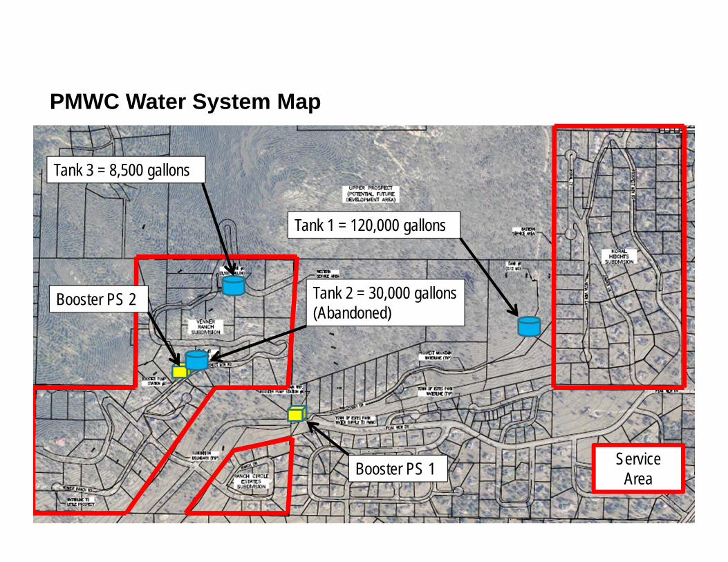
PMWC Water System Map
Tank 3 = 8,500 gallons
Tank 1 = 120,000 gallons
Booster PS 2
Booster PS 1
Tank 2 = 30,000 gallons(Abandoned)
Service Area

PMWC Water System Hydraulic Profile
Source: Master System Improvements Plan, FEI Engineers

Attachment 2
PMWC Sanitary Survey


Attachment 3
CDPHE Telephone Records

hdrinc.com
1
Telephone Record Date: Monday, June 22, 2015
Project: Integration of PMWC with Town of Estes Park Project No: 259020
Call to: Tyson Ingels (CDPHE) Phone No: 303-692-3002
Call from: Jennifer Stillman (HDR) Phone No: 303-318-6334
Subject: Compliance impacts from operation and/or integration of PMWC (Deliberative)
Discussion, Agreement, and/or Action:
1. Tyson confirmed that the Town can take over operations of the PMWC system and still maintain its status as a consecutive system (i.e. the Town will not be legally responsible for PMWC’s compliance with drinking water regulations).
2. The only paperwork that needs to be done to take over operation is a short update to PMWC’s “Monitoring Plan” to document that the Town is taking over as the ORC (operator in responsible charge). This will let PMWC’s compliance officer (at CDPHE) know that the Town is taking over operation.
3. Frank Huffman should have a copy of PMWC’s Monitoring Plan or we can request it from the compliance officer. Tyson has requested that the compliance officer contact me.
4. Legal enforcement of regulatory compliance only applies to the owner of the water system and not to the operator of the system.
5. The operator of the system is still bound by the ethics of Regulation 100 (CDPHE Water and Wastewater Facility Operators Certification Requirements, Regulation 100, 5 CCR 1003-2).
6. If the PMWC is under increased water quality monitoring requirements, then these requirements will also apply to the Town’s entire water system as soon as they take over ownership of the PMWC water system. Tyson provided an example that Denver Water had to notify all of its customers regarding a lead and copper violation, even though they knew the problem was only present in Washington Park.
7. If the PMWC is out of compliance on any regulations or under increased monitoring, then Tyson recommends operating the system and maintaining the “consecutive” status until all requirements have been met for 1-1.5 years.
8. CDPHE does have a precedent for allowing water systems to implement lead and copper treatment (such as feeding a corrosion inhibitor or sequestering agent) in specific neighborhoods. This would require design approval from CDPHE.

hdrinc.com
2
9. Tyson did a query on CDPHE’s database to review the PMWC’s “Comprehensive Report” and “Sanitary Survey”. The Town may make a COR (Colorado Open Records Act) request to see these documents. Tyson shared the following from the documents:
a. The PMWC is not currently under enforcement status with CDPHE. b. The PMWC had a lead violation in June 2014. Lead was measured at 28 ppb and the
maximum contaminant level (MCL) is 15 ppb. c. The PMWC is supposed to be completing a lead and copper study. d. There were no documented violations of coliforms, DBPs, or chlorine residual. e. The PMWC has had a significant number of monitoring violations over the past decade.
This means they failed to take/report required samples. f. Significant system deficiencies were noted with regards to storage tanks on the sanitary
surveys conducted in 2012 and 2014. g. There was no record of the Little Prospect water system in the CDPHE database. This is
probably because the system serves less than 25 people, so it is not considered a public water system.
10. The Town and HDR will need to work with PMWC’s compliance officer if the Town wants to take
over ownership of PMWC. This can be done via phone and email and a formal meeting with CDPHE is not required. However, CDPHE is very willing to have a “sit-down” meeting, if it would help with negotiations and decision-making for the parties involved.
11. CDPHE recently assisted City of Granby with a similar take-over of a trailer park water system. The assistance included identification of loans.

hdrinc.com
1
Telephone Record Date: Tuesday, September 22, 2015
Project: Integration of PMWC with Town of Estes Park Project No: 259020
Call to: Tyson Ingels and Nicole Graziano (CDPHE) Phone No: 303-692-3002
Call from: Jennifer Stillman (HDR) Phone No: 303-318-6334
Subject: Town Ownership of PMWC as a Second Public Water System (Deliberative)
Discussion, Agreement, and/or Action:
1. Nicole stated that PMWC has a significant history of lead and copper exceedances. They have exceeded the action level during sampling in 2010, 2011, 2012, and 2014. Several samples collected in 2014 exceeded the action level, but the 90% percentile did not trigger a violation.
2. The last two rounds of lead and copper sampling have been in compliance (i.e. not a violation). These samples were collected in Dec. 5-31, 2014 and June 12-19, 2014.
3. The State will put PMWC on reduced monitoring starting in January of 2016. At this time, they will be required to perform one round of lead and copper sampling per year for the next three (3) years.
4. CDPHE cannot reduce the 3 year annual monitoring requirement because EPA has primacy on the lead and copper rule.
5. Jenn stated that the Town may request to take over ownership of PMWC, but still maintain it as a separate public water system, so that the Town’s system does not become non-compliant for lead and copper. Jenn asked if there was an avenue at CDPHE for this situation.
6. Tyson said that the regulations do not prohibit this. However, it will most likely be a new precedent for an entity to take ownership of a consecutive system, while still maintaining it as a separate water system. Tyson stated that this is a unique case.
7. The Town would still be required to operate the PMWC as a separate water system with its own monitoring plan and inspections.
8. Tyson stated that CDPHE’s director, Ron Falco, would need to approve the Town’s request and it will probably also need approval from CDPHE legal council. The legal council is an Attorney General who is assigned to assist the CDPHE.
9. If the Town wants to proceed with ownership, then they need to submit a formal request on Town letterhead to the CDPHE. The letter should be addressed to PMWC’s compliance officer, Erica Kannely. (Nicole is Erica’s boss and Erica was out on vacation today.)
10. The request letter should include the following points: a. The Town does not want to incur lead and copper compliance monitoring associated with
PMWC. b. Maintaining PMWC as a separate water system is more protective of public health. c. There is a history of PMWC being its own water system. d. The Town intends to fully integrate the PMWC into its own water system in the future.
11. Tyson stated that the legal approval could take some time since this may set a precedent at the CDPHE, but they are supportive of the Town and appreciate of their efforts to help a small water system.