pmc-sf patrol motorcycle special forces...patrol motorcyle, special forces (pmcisf) the pmc-sf is...
TRANSCRIPT

UN
CO
NTR
OLL
ED IF
PR
INTE
D
PMC-SF
Patrol Motorcycle Special Forces Addendum to Service Manual - lssue 3
AS1NZS IS0 9001 : 2000 Certificate No: MEQ4000127
ale
Part No. BDI-9937
UN
CO
NTR
OLL
ED IF
PR
INTE
DELECTRICAL AND MECHANICALENGINEERING INSTRUCTIONS
VEHICLE A 126-2Issue 2, May 10
AEidandum Eo Sgnside Manual W - S F
Patrol Motarcycle, Special Fotces (PMCSF)
Contents
Ovehview Machine Profib Spring, Heavy Duty, Rear Shock Clutch Lock Whee1s & Spokes Plastic, Acerbis Headlamp Switchgear Wiring Diagram Fans & Thermoswitch Acerbis 18 Litre Fuel Tank - (if fitted) Auxdiary Fuel Tank - ( I f fitted) Radiator Guards Bashplate f race Wires s a t Cover Tank Cover Handlebars & Barkbusters Frunt Disc Protector - Acerbis (Obsolete) Front Disc Protector - BDI 15642 (Replacement far Acerbis) Kick Starter Kit Black Vinyl Adhesive Talon Suspensiun Links - (if fitted)
Page 2 -3 Pa3e4&5 - 6 pw@ 7 page 8 Page9& 10 Page 10 & 11 Page 12 Page 13 Page 14 to 17 Page 18 & 49 Page 20 8 21 Page 22 Page 23 Page 24 Page 24 & 25 Page 26 Page 27 Page 28 Page 29 Page 29 Page 30
VEHICLE B 126-2Issue 2, May 10
ELECTRICAL AND MECHANICALENGINEERING INSTRUCTIONS
Patrol Motorcyle, Special Forces (PMCISF)
The PMC-SF is based on a Suzuki DRZ 400E motorcycle. The base motorcycle has been reconfigured to suit the requirements of the Special Forces. This manual is a supplement to the Suzuki OEM Service Manual and should be read in conjunction with that manual. It deals only with the modifications made to the Suzuki DRZ 400E to convert it to the PMC-SF specification, and in no way replaces or overrides the OEMs requirements with regard to maintenance or repair.
The features specific to the PMC-SF am: Replacement of OEM plastics (mudguards, sidecovers, radiator cowling) with black Acerbis plastics. Replacement of OEM headlamp unit with Motoplus RXT Twin Enduro headlamp.
e Replacement of OEM spokes with black xylan coated stainless steel spokes a Black powdercoating of wheel rims
Fitment of black Acerbis or BDI 15M2 front disc protector. Reconfiguration of lighting switches and wiring harness, Fitment of black aluminium bash plate.
a Fitment of black aluminium radiator guards. Fitment of black aluminium rear carry rack, with extension for toolkit. (if fitted) Fitment of 7.5 litre auxiliary fuel tank to rear carry rack. (If fitted) Fitment of Acerbis 16 litre fuel tank (If fitted) Fitment of trace wires to gear and brake levers. Fitment of two electric powered fans controlled by a themtoswitch. Fitment of thermoswitch Fitment of kick starter kit. (OEM option).. Fitment of tank and seat covers made from DCPM material. Fitment of high yield handlebars and grips. Fitment of Barkbuster hand protectors. Fitment of clutch locking mechanism. Fitment of 11 Okg rated spring to rear shock absorber. Application of black vinyl sheeting to swing arm, upper & lower fork legs Removal of Prop Stand and Clutch safety switches.
The PMC-SF is capable of operating in extreme climatic conditions (-36 degrees C to +57 degrees C) provided the correct coolant ratio and full synthetic lubricants are used.
Page 2
ELECTRICAL AND MECHANICALENGINEERING INSTRUCTIONS
VEHICLE B 126-2Issue 2, May 10

Page 3
VEHICLE B 126-2Issue 2, May 10
ELECTRICAL AND MECHANICALENGINEERING INSTRUCTIONS

Spring - Rear Shock Absorber
Refer also Suzuki DRZ 400E Sewice Manual Part 6-31
The PMC-SF has a heavy duty spring fitted to the rear shock absorber to improve the load carrying ability of the machine. The spring itself requires no maintenance and is guaranteed for life against factory defects in material & workmanship.
Spring Adjustment - Static Sag
Static Sag is the amount the bike settles from fully extended with the rider on board. This should be adjusted to suit weight of the rider. It may have to be altered if the load is increased. Optimum setting is about 30 to 33% of total suspension travel. If you have too much static sag, spring preload should be increased. If there is too little static sag, spring preload should be decreased. (Preload is the distance the spring is compressed from its free length to its installed length on an assembled and fully extended shock.) To measure static sag:
Place the machine on a stand and measure vertically from the rear axle to a point on the chassis. Mark this point. We will call this distance L1.
k Take the machine off the stand, have the rider (and load, if applicable) aboard and push down on the rear end. Then let it extend very slowly. Do not bounce. Measure the distance from chassis mark to axle. Call this L2.
P Still with rider (and load if applicable) aboard, lift the rear end and let it drop very slowly. Do not bounce. Measure again the distance from chassis mark to axle. Call this L3. The two measurements will be different due to drag in the linkage.
> Distances L2 and L3 should be averaged and subtracted from L1 to calculate the true Static Sag.
9 Static Sag = L1 - (L2 + L3)12
The pre-load collar should be adjusted to obtain the desired amount of sag. More preload will cause the back of the motorcycle to ride higher in it's travel, while less pre-load will cause it to ride lower. The amount of preload would not normally exceed 15mm. When the desired setting has been achieved tighten the Lock Ring to 90N.m (9.Okgf-m, 65.Olb-ft).
The static sag is adjusted by loosening the Spring Adjuster Lock Ring (C) and turning the Spring Adjuster (2) to achieve the desired setting.
Page 4
0--0
Parts Key A Shock Absorber Nut B Shock Absorber Comp.
Adjuster Assy C Spring Adjuster Lock
Ring
1 Rear shock absorber 2 Spring adjuster 3 Spring 4 Spring seat 5 Cirdip
L
ELECTRICAL AND MECHANICALENGINEERING INSTRUCTIONS
VEHICLE B 126-2Issue 2, May 10
Spring - Rear Shock Absorber (continued)
Free Sag Free Sag is the amount the unladen motorcycle will settle under its own weight. The Free Sag should be measured using the same procedure as for Static Sag, but without rider or load. The rear of motorcycle should compress about 5% to 8% (approximately 15 to 25mm) of its travel from the fully extended position. If Static Sag is correct and there is too little free sag, a stiffer spring with less preload is recommended. If Static Sag is correct and there is too much Free Sag, a lighter spring with more preload is recommended.
Shack Absorber Damping Compression and rebound damping of the rear shock absorber should be adjusted to suit the load being carried as per Suzuki DRZ 400E Service Manual part 6-39.
Page 5
VEHICLE B 126-2Issue 2, May 10
ELECTRICAL AND MECHANICALENGINEERING INSTRUCTIONS

Clutch Lock
A clutch locking device has been fitted to the PMC-SF which enables the operator to leave the machine running while in gear, with the clutch disengaged.
Disengaged Position
-_--- L-- //-' __--- Clutch Lock
Engaged Position
1
The mechanism is a simple spring loaded clip and requires occasional lubrication of the pivot point with light oil. This should be done at every major service.
Caution:
It is imperative that the correct clutch adjustment be maintained. Should the clutch lock be employed when the clutch is dragging through maladjustment, the engine will stall or the machine could be propelled forward, with or without the rider, possibly causing damage. Refer Suzuki DRZ 400E Owner's Manual Part 6-16 for clutch adjustment procedure.
Page 6
ELECTRICAL AND MECHANICALENGINEERING INSTRUCTIONS
VEHICLE B 126-2Issue 2, May 10

Wheels
Refer Also Suzuki ORZ 400E Service Manual Part 6-3 and 6-25
Wheel rims fitted to the PMC-SF are Suzuki standard fitment Excel Takasago aluminium rims, powdercoated black. Although the finish is very durable, it will chip if roughly handled and care should be taken when changing tyres etc.
Stainless steel spokes have been used for corrosion resistance and low maintenance. The spokes have a black xylan surface treatment for durability and low sheen. The coating is only microns thick and will not interfere with spoke nipple adjustment.
Spoke condition is vital for rider safety. The wheels should be checked for broken or missing spokes each time the machine is ridden.
Broken spokes must be replaced. Continued use of a wheel with broken spokes will cause further breakages and eventual failure of the wheel. Spoke replacement is best left to a specialist wheel builder. Consult your nearest Suzuki agent.
Tension of spokes should be checked periodically. Any loose or broken spokes will make a dull sound when struck with a screwdriver or similar small metal bar. This should be undertaken after the first 5 hours of operation and every 30 hours thereafter.
Loose spokes will place uneven loads on other spokes and may cause other spokes to break and/or excessive wheel rim runout. Spoke nipples should be adjusted evenly with a spoke nipple key or wrench to bring runout into tolerance. Recommended torque on spoke nipples is 3.0 N.m (0.3 kgf-rn, 2.0 Ib-ft). Refer Suzuki DRZ 400E Service Manual Part 2-22
Spoke Adjustment
Page 7
VEHICLE B 126-2Issue 2, May 10
ELECTRICAL AND MECHANICALENGINEERING INSTRUCTIONS
Plastics
Refer Also Suzuki DRZ 400E Service Manual Part 6-2
The standard Suzuki plastics (front and rear mudguard, side panels and radiator cowls) have been replaced with black Acerbis aftermarket parts to make the PMC-SF less obtrusive. The removal and remounting of these is dealt with in Suzuki DRZ 400E Service Manual Part 6-2.
Should any of these parts require replacement there are some minor modifications that need to be performed if the 7 litre Auxiliary Fuel Tank is to be fitted (pages 18 & 19).
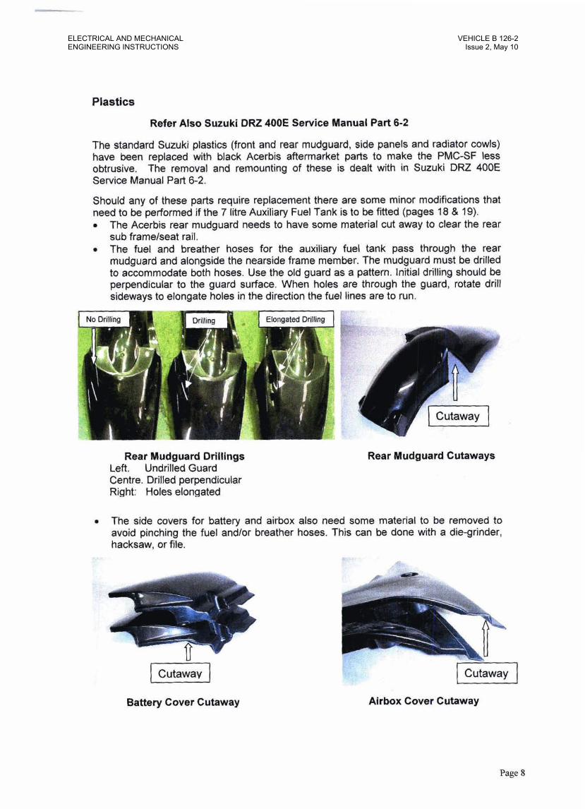
The Acerbis rear mudguard needs to have some material cut away to clear the rear sub framelseat rail. The fuel and breather hoses for the auxiliary fuel tank pass through the rear mudguard and alongside the nearside frame member. The mudguard must be drilled to accommodate both hoses. Use the old guard as a pattern. Initial drilling should be perpendicular to the guard surface. When holes are through the guard, rotate drill sideways to elongate holes in the direction the fuel lines are to run.
Rear Mudguard Drillings Left. Undrilled Guard Centre. Drilled perpendicular Right: Holes elongated
Rear Mudguard Cutaways
The side covers for battery and airbox also need some material to be removed to avoid pinching the fuel andlor breather hoses. This can be done with a die-grinder, hacksaw, or file.
1 Cutaway I
Battery Cover Cutaway Airbox Cover Cutaway
Page 8
ELECTRICAL AND MECHANICALENGINEERING INSTRUCTIONS
VEHICLE B 126-2Issue 2, May 10

Headlamp 8 Electrical System
Refer also Suruki DRZ 400E Service Manual Part 7-1 to 7-29 and 9-17
Various changes have been made to the Suzuki DRZ 400E electrical system to enable it to be used in PMC-SF configuration.
It has received a twin lens headlamp unit with revised switchgear, to enable night time use under white light, infra red or complete black out. Twin electric fans controlled by a thennoswitch have been fitted to improve its cooling capacity in extreme heat. The standard fitment side stand and clutch safety switches have been removed to avoid possible confusion if a quick getaway is called for.
Headlamp
The headlamp used is a Motoplus RXT Twin Enduro headlamp, which has been chosen for its containment of reaward emergent white light (essential for use with NVG equipment). This is achieved by having close fitting shells around the headlamp reflectors. A viton (heat resistant) o-ring is fitted in the air gap between the shells to further reduce the amount of rearward light emission. The lights themselves burn very hot (up to 180 degrees C) and should not be run for extended periods without fonvard motion. Reduced aidow can cause premature failure.
Headlamp Unit Headlamp Securlng B o b
To replace a blown globe, release the bolts securing the headlamp brackets to the fork brackets and swing the headlamp unit forward. The rear of the unit will now be accessible.
Rear of Headlamp Two Pin Plug
Page 9
VEHICLE B 126-2Issue 2, May 10
ELECTRICAL AND MECHANICALENGINEERING INSTRUCTIONS

Headlamp & Electrical System
Headlamp (continued)
Remove the Phillips head screw securing the Teflon end cap to the reflector shell and slip the cap back up the leads. Three Phillips head screws retain the reflector shell. When these are removed the reflector shell, o-ring and globe will be released. The reflector shell can be slipped back up the leads and the two pin (female) plug removed from the globe. Replacement is the reverse of removal procedure. Take care to refit the Viton (brown) o-ring, and Teflon end cap which are essential for light seal, and the Silicon (white) gasket which goes in front of the lens.
-3- I Teflon End C ~ D
- -
( Viton 0-Ring I
Reflector Shell Light Seals
Switchgear
The lighting functions of the PMC-SF are controlled by auxiliary switches mounted on the handlebar.
- -1
Light Swil as - g 1
I Blackout S w M ( c ) - - - 1
See revised wiring diagram page 13.
Page 10
ELECTRICAL AND MECHANICALENGINEERING INSTRUCTIONS
VEHICLE B 126-2Issue 2, May 10
Headlamp & Electrical System
Switchgear (continued)
The headlamp and blackout switches enable the motorcycle to be used in the following configurations
Standard "Lights On" mode as supplied by the manufacturer, "Lights Off' mode, with all electrical functions operative except the headlamp, "Blacked Out" mode, where the electric starter will spin the motor, but no lighting functions or horn will operate (except for speedo display). "NVG" mode, similar to "Blacked Out" but an IR lens is secured over the low beam lamp to give 1.R. capability.
The Ignition Switch, Switch a. provides current to the starter motor, ignition, speedo display, and to all other circuits via the auxiliary switches Switch b and Switch c. With the Ignition Switch in the "Oh" position, the motor will start and run, regardless of the position of auxiliary switches. (F&T switch Identification refer Fig. I on Page 70)
"Lights OnJ' - The Headlamp Switch, Switch b, controls headlamp unit and the Blackout Switch, Switch c. overrides all other lighting & accessory circuifs. With both Switches b and c in the "On" position all lighting & accessory circuits will be fully operational.
"Lights Off " - When Switch c, is in the "Onn position, but Swifch b. is in the "Off' pasition, all lighting & electrical functions will operate except the headlamp.
"Blacked Out" - When Switch c. is in the "OW position and Swifch 6. is also in the "Off' position, no lights or accessories will operate. The motorcycle will be completely 'blacked out" (except for the speedo display & it's background illumination on K7 models), but the motor will still start & run.
"NVG" - If Switch 6. is turned "On", while Switch c. remains "Off', only the headlamp (and speedo display & background illumination on K7 models) will operate. The dimmer switch (switch d) on the left handlebar block is then used to switch from white light (high beam) to IR light (low beam). The background illumination from the speedo display on K7 models will interfere with NVG equipment and the instrument must be taped over when using NVGs.
Clutch Lever Position Switch & Sideatand Switch
Clutch Lever Position Switch and Side-Stand Switch Refer Suzuki DRZ400E Service Manual Part 7-29 and 9-17 which are standard fitment to the Suzuki DRZ4OOE have been removed from the PMC-SF.
See revfsed wiring diagram Page 13.
The clutch switch has been removed to allow the provision of the clutch lock. Operators must take care not to start the machine in gear without disengaging the clutch.
The side-stand switch has been removed to avoid confusion in the event of a rapid response. However, operators must take care to retract the side-stand before moving off.
Page 1 I
VEHICLE B 126-2Issue 2, May 10
ELECTRICAL AND MECHANICALENGINEERING INSTRUCTIONS
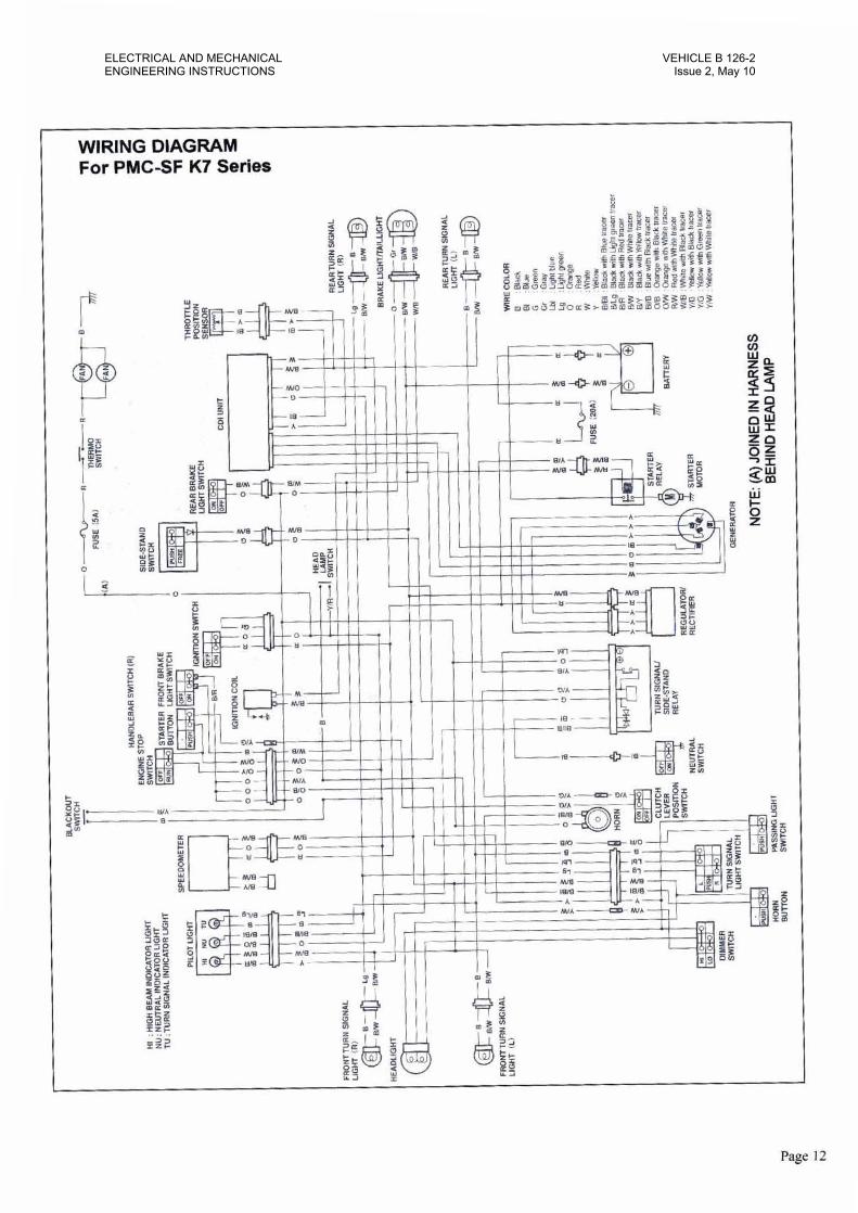
WIRING DIAGRAM For PMCSF K7 Series
Page 12
ELECTRICAL AND MECHANICALENGINEERING INSTRUCTIONS
VEHICLE B 126-2Issue 2, May 10
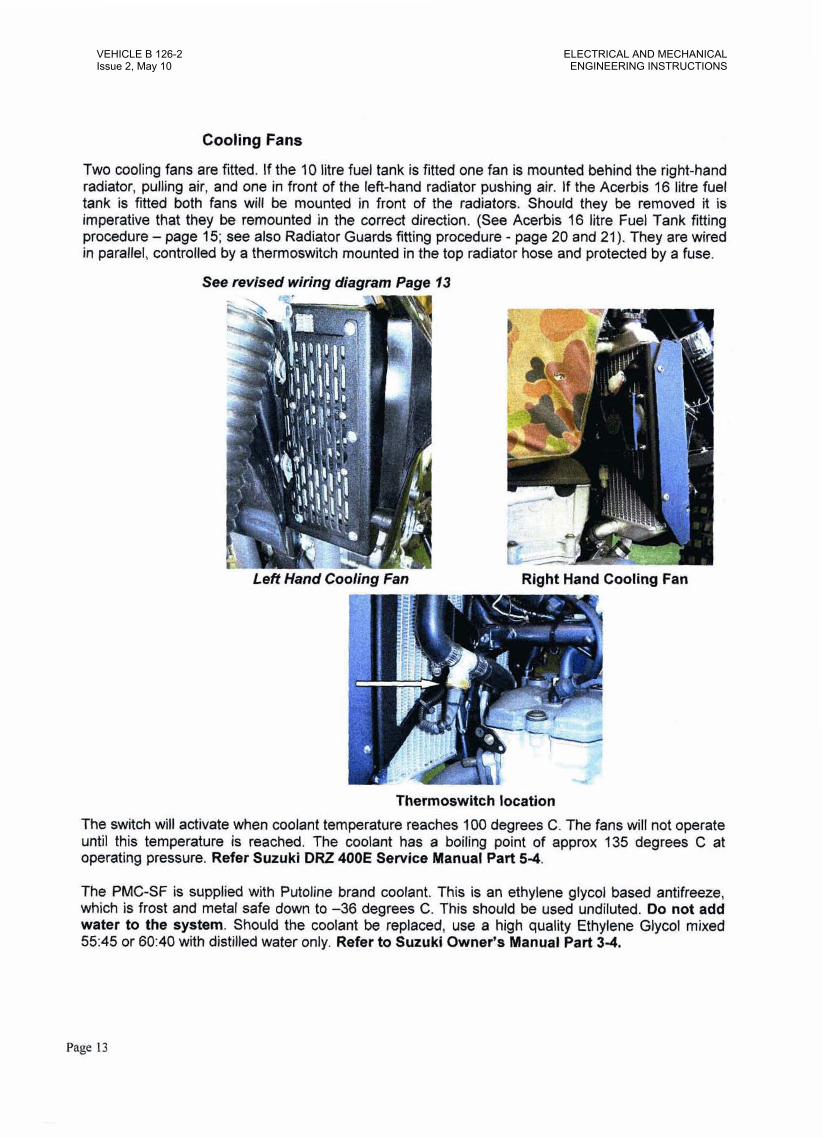
Cooling Fans
Two cooling fans are fitted. If the 10 litre fuel tank is fitted one fan is mounted behind the right-hand radiator, pulling air, and one in front of the left-hand radiator pushing air. If the Acerbis 16 litre fuel tank is fitted both fans will be mounted in front of the radiators. Should they be removed it is imperative that they be remounted in the correct direction. (See Acerbis 16 litre Fuel Tank fitting procedure - page 15; see also Radiator Guards Wing procedure - page 20 and 21). They are wired in parallel, controlled by a thermoswitch mounted in the top radiator hose and protected by a fuse.
See revised wiring diagram Page f 3
Right Hand Cooling Fan
Thermoswitch location The switch will activate when coolant temperature reaches 100 degrees C. The fans will not operate until this temperature is reached. The coolant has a boiling point of approx 135 degrees C at operating pressure. Refer Suzuki DRZ 4OOE Service Manual Part 5-4.
The PMC-SF is supplied with Putoline brand coolant. This is an ethylene glycol based antifreeze, which is frost and metal safe down to -36 degrees C. This should be used undiluted. Do not add water to the system. Should the coolant be replaced, use a high quality Ethylene Glycol mixed 5545 or 60:40 with distilled water only. Refer to Suzuki Owner's Manual Part 34.
Page 13
VEHICLE B 126-2Issue 2, May 10
ELECTRICAL AND MECHANICALENGINEERING INSTRUCTIONS
kerbis 16 Litre Fuel Tank - If fitted. The 76 litre tank is available as an alternative to the standard OEM fuel tank of 10 litres capaciQ. Some modifications are required to fit the larger tank to Me PMC-SF. Bale Defence industries PC/ Ltd supply a kit with all parts required for he conversion. Part No. BDI 15646. (Replacement parts are available separately if required.)
The kit comprises the following parts: 1 x 16 litre fuel tank, complete wlth, 2 fuel taps, fiikr cap, fuel lines and breather hose 1 x DPCM tank cover 1 x Replacement bracket for nearside radiator guard
1 2 x Replacement radiator hoses 2 x 20mm x M6 shcs, (Replacement screws for seat mounts) 4 x 16mm x M4 Phillips head screws for securing right hand fan to inside of radiator grille 2 x Small quick ties for securing electrical leads to the right hand fan to the motorcycle to frame
* 4 x Large quick ties far securing clutch and throttle cables to top frame tube d necessary. 350mm x 6mm fuel hose and 80mm x 6mm fuel hose
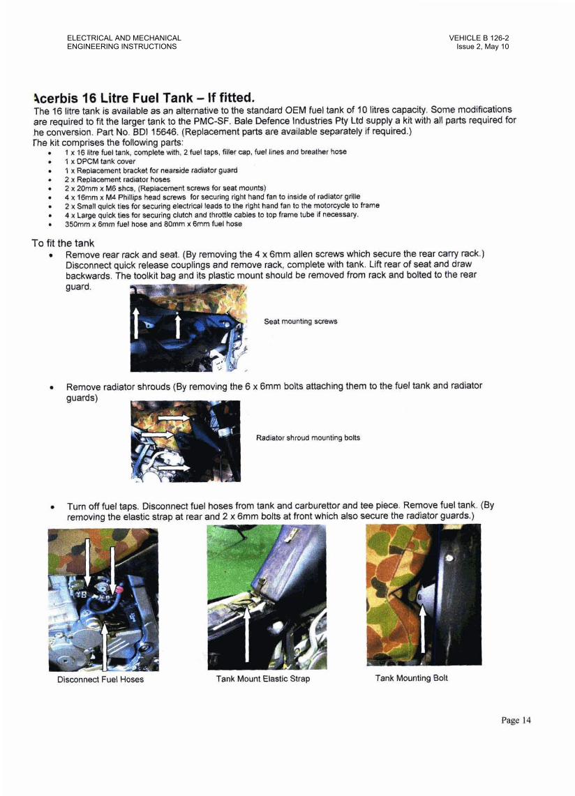
To fit the tank r Remove rear rack and seat. (By removing the 4 x 6mm allen screws which secure the rear carry rack.)
Disconnect quick release couplings and remove rack, complete with tank. Lift rear of seat and draw backwards. The toolkit bag and its plastic mount should be removed from rack and bolted to the rear guard.
Seat mounting screws
Remove radiator shrouds (By removing the 6 x 6mm bolts attaching them to the fuel tank and radiator - guards)
I Radiator shroud mounting bolts
Turn off fuel taps. Disconnect fuel hoses from tank and carburettor and tee piece. Remove fuel tank. (By removing the elastic strap at rear and 2 x 6mm bolts at front which also secure the radiator guards.)
Disconnect Fuel Hoses Tank Mount Elastic Strap Tank Mounting Bolt
Page 14
ELECTRICAL AND MECHANICALENGINEERING INSTRUCTIONS
VEHICLE B 126-2Issue 2, May 10
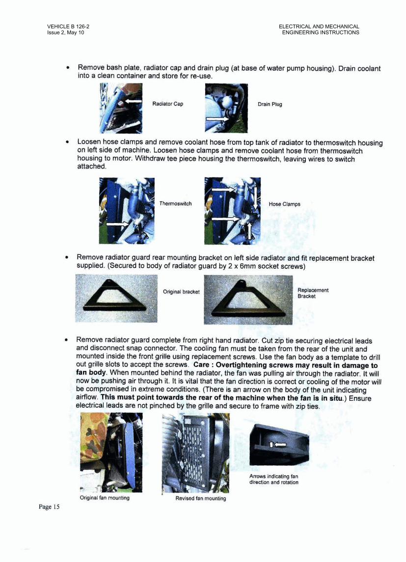
Remove bash plate, radiator cap and drain plug (at base of water pump housing). Drain coolant into a clean container and store for re-use.
Drain Plug
* Loosen hose clamps and remove coolant hose from top tank of radiator to thermoswitch housing on left side of machine. Loosen hose clamps and remove coolant hose from therrnoswitch housing to motor. Withdraw tee piece housing the thermoswitch, leaving wires to switch attached.
Remove radiator guard rear mounting bracket on left side radiator and fit replacement bracket supplied. (Secured to body of radiator guard by 2 x 6rnm socket screws)
Remove radiator guard complete from right hand radiator. Cut zip tie securing electrical leads and disconnect snap connector. The cooling fan must be taken from the rear of the unit and mounted inside the front grille using replacement screws. Use the fan body as a template to drill out grille slots to accept the screws. Care : Overtightening screws may result in damage to fan body. When mounted behind the radiator, the fan was pulling air through the radiator. It will now be pushing air through it. It is vital that the fan direction is correct or cooling of the motor will be compromised in extreme conditions. (There is an arrow on the body of the unif indicating airflow. This must point towards the mar of the machine when the fan is in situ.) Ensure electrical leads are not pinched by the grille and secure to frame with zip ties.
Original fan mounting Revised fan mounting
Arrows indicating fan direction and rotation
Page 15
VEHICLE B 126-2Issue 2, May 10
ELECTRICAL AND MECHANICALENGINEERING INSTRUCTIONS

a Transfer the seat securing bracket and front mounting brackets from the old to the nesn tank, Fit DPCM cover to 16 litre tank. Pull the cover over the filler neck and seat securing ckp and stretch tight over the tank. Now turn the tank over and pull the apertures tight arourr$#e fuel taps. Tie off drawstring on one side. Pull draw string tight and tie off on the other side. Excess string should be tucked inside the cover rather than cut off, as this will make it diffimkto re- secure if the cover is removed in the future.
Seat securing bracket Front mounting bracket Excess cord tucked inside cover
a The replacement coolant hoses are marked with a white and yellow dot. The white dot indicates which end of the hose fits to the cylinder head and the yellow dot which end fits to radiator top tank. Fit the unmarked end of each hose to the thermoswitch housing. Place hose clamps loosely on the hoses, Fit coolant hoselthermoswitch assembly between the upper left radiator tank and the cylinder head, and align the thermoswitch housing so that the switch points towards the centre of the machine. Adjust hose orientation to suit. Tighten all four hose clamps.
Hose assembly ready for installation. Dots a n indicated.
6 1 R V
Thermoswitch alignment
Refit drain plug to water pump housing. Refit bash plate. Fill system with coolant and bleed air from system via bleed valve in left hand top tank. Refer to Suzuki Service Man& part 2-15.
Page 16
ELECTRICAL AND MECHANICALENGINEERING INSTRUCTIONS
VEHICLE B 126-2Issue 2, May 10
Page 17
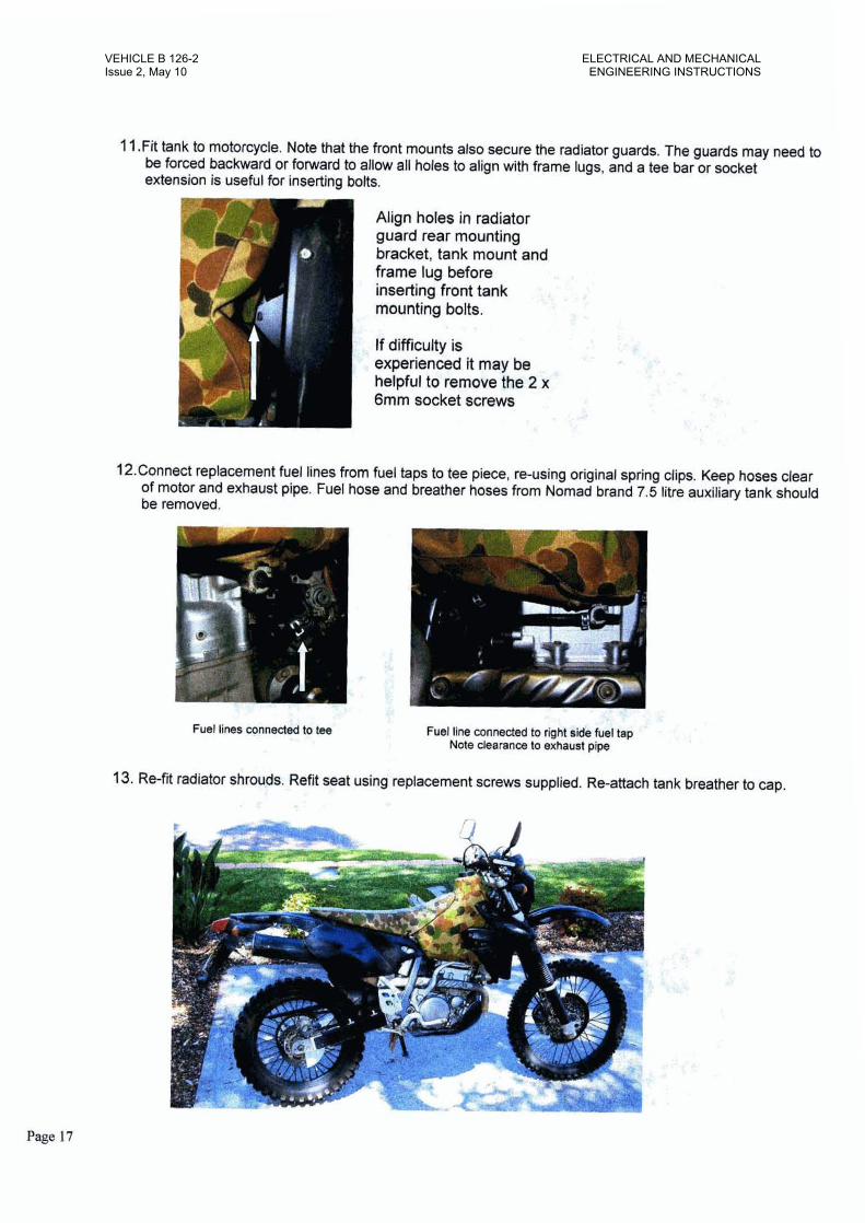
11 .Fit tank to motorcycle. Note that the front mounts also secure the radiator guards. The guards may need to be forced backward or folward to allow all holes to align with frame lugs, and a tee bar or socket extension is useful for inserting bolts.
Align holes in radiator guard rear mounting bracket, tank mount and frame lug before , . - -.I , . inserting front tank >z,$. .Am. . ,r ' .. ", ' . 2 ,!'
mounting bolts. ' . I'
- ,, - 2 . 4 =
7 ' * ,
If difficulty is , mu.A - , \: . ;,, $: .7
experienced it may be *. -3:" - <. 'f
helpful to remove the 2 x 7 ,:; . - ..- - coJ .. '
6mm socket screws h , -=- I f ; :
-. - , - , - < - ' I .
r, , :; .!I' >:,
4.3, - :-- ." .:-. . . . 1. -I. /.. -
12.Connect replacement fuel lines from fuel taps to tee piece. re-using original spring clips. Keep hoses clear of motor and exhaust pipe. Fuel hose and breather hoses from Nomad brand 7.5 litre auxiliary tank should be removed.
, . & + $ , , : ,: Fuel line connected to right sde fuel tap , :: ,
'
1 Note clearanm to exhaust pipe
13. Re-fit radiator sh&ds. Refit seat using replacement screws supplied. Re-attach tank breather to cap, ., *' A .
VEHICLE B 126-2Issue 2, May 10
ELECTRICAL AND MECHANICALENGINEERING INSTRUCTIONS
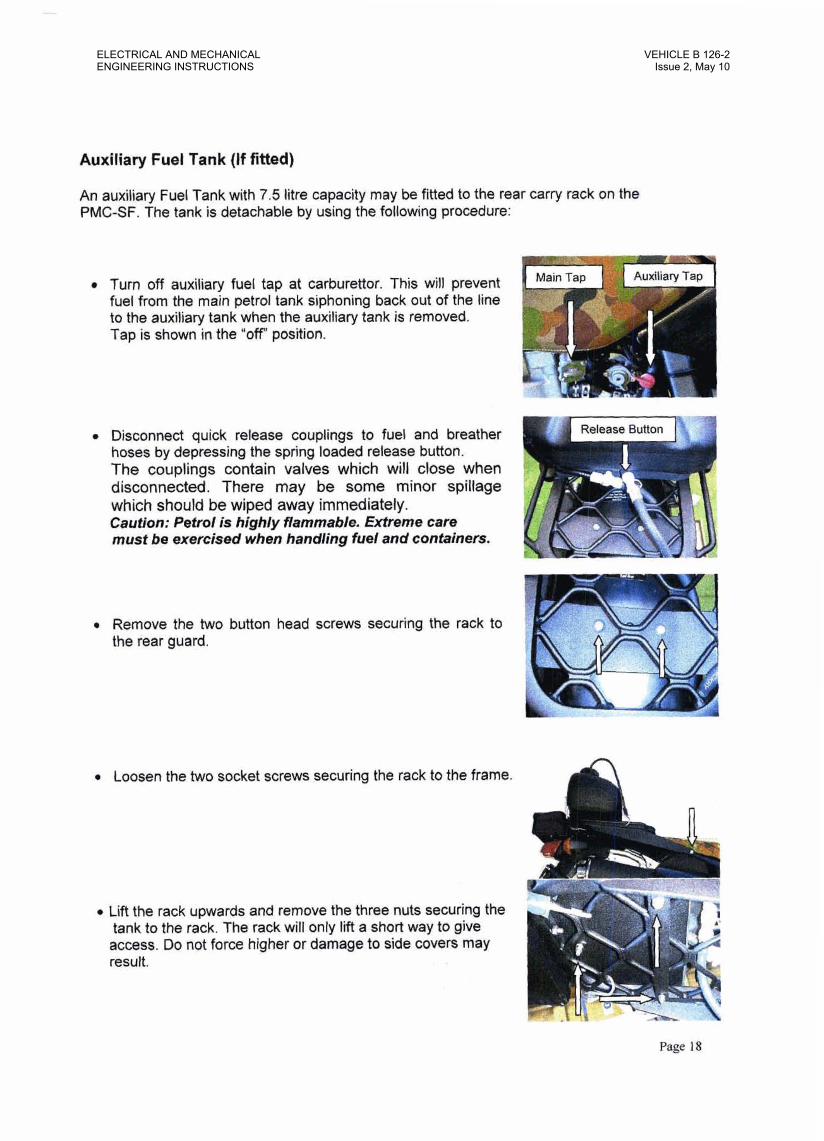
Auxiliary Fuel Tank ( I f fitted)
An auxiliary Fuel Tank with 7.5 litre capacity may be fitted to the rear carry rack on the PMC-SF. The tank is detachable by using the following procedure:
r Turn off auxiliary fuel tap at carburettor. This will prevent fuel from the main petrol tank siphoning back out of the line to the auxiliary tank when the auxiliary tank is removed. Tap is shown in the "off' position.
Disconnect quick release couplings to fuel and breather 1 Release Button
hoses by depressing the spring loaded release button. The couplings contain valves which will close when disconnected. There may be some minor spillage which should be wiped away immediately. Caution: petrol is highly fla&ble. Extreme care must be exercised when handling fuel and containers.
Loosen the two socket screws securing the rack to the frame.
Lift the rack upwards and remove the three nuts securing the tank to the rack. The rack will only Ilft a short way to give access. Do not force higher or damage to side covers may result.
Remove the two button head screws securing the rack to the rear guard.
ELECTRICAL AND MECHANICALENGINEERING INSTRUCTIONS
VEHICLE B 126-2Issue 2, May 10

Auxiliary Fuel Tank (continued) - If fitted
Caution: Petrol is highly flammable. Extreme care must be exercised when handling fuel and containem.
Replace screws attaching rack to the rear guard and tighten screws attaching front of rack to frame Tighten Screws to 20N-rn (2.0 kgf-m, 14.5 lb-fi) Interconnect the fuel and breather hoses on the motorcycle to avoid the ingress of dirt or moisture. Repeat the procedure with the fuel and breather hoses attached to the tank
- I 1' Q u
a ., Tank Installed Hoses Interconnected after Hoses connected Tank Removal
A filter is installed in the fuel line, accessible under the air cleaner cover. It should be checked visually each time the air cleaner is serviced.
1
Breather
A one-way valve is fitted in the breather hose to prevent fuel leakage. If the hose is removed from the tank cap it must be replaced with the valve in the same direction or the valve could prevent air entering the tank and cause fuel starvation.
Page 19
VEHICLE B 126-2Issue 2, May 10
ELECTRICAL AND MECHANICALENGINEERING INSTRUCTIONS
Radiator Guards
Aluminium radiators are fitted to the Suzuki DR-Z400E for efficiency and light weight. These vital components are vulnerable to accident damage, and the PMC-SF is equipped with heavy-duty aluminium guards to protect them.
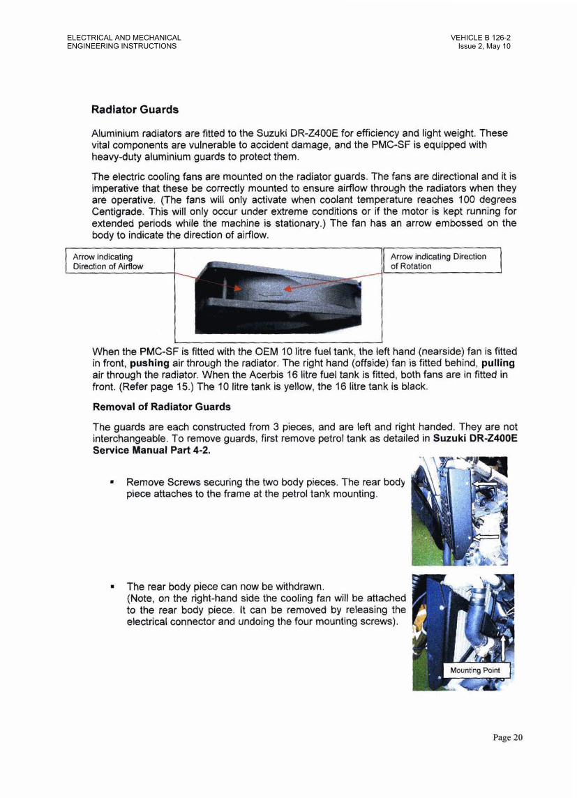
The electric cooling fans are mounted on the radiator guards. The fans are directional and it is imperative that these be correctly mounted to ensure airflow through the radiators when they are operative. (The fans will only activate when coolant temperature reaches 100 degrees Centigrade. This will only occur under extreme conditions or if the motor is kept running for extended periods while the machine is stationary.) The fan has an arrow embossed on the body to indicate the direction of airflow.
1 Arrow indicating I (1 Arrow indicating Direction 1
When the PMC-SF is fitted with the OEM 10 litre fuel tank, the left hand (nearside) fan is fitted in front, pushing air through the radiator. The right hand (offside) fan is fitted behind, pulling air through the radiator. When the Acerkis 16 litre fuel tank is fitted, both fans are in fitted in front. (Refer page 15.) The 10 litre tank is yellow, the 16 litre tank is black.
Removal of Radiator Guards
The guards are each constructed from 3 pieces, and are left and right handed. They are not interchangeable. To remove guards, first remove petrol tank as detailed in Suzuki DR-Z400E Service Manual Part 4-2.
Remove Screws securing the two body pieces. The rear body piece attaches to the frame at the petrol tank mounting.
The rear body piece can now be withdrawn. (Note, on the right-hand side the cooling fan will be attached to the rear body piece. It can be removed by releasing the
1 electrical connector and undoing the four mounting screws),
Mounting Point
Page 20
ELECTRICAL AND MECHANICALENGINEERING INSTRUCTIONS
VEHICLE B 126-2Issue 2, May 10

Radiator Guards (cont'd)
Remove the 5 screws securing the front grille. (Note, on the lefl-hand side the cooling fan will be attached to the front grille. It can be removed with the grille by releasing the electrical connector, and removed from the grille by undoing four screws).
Remove radiator mounting bolts which are now accessible through the opening. These bolts secure both the radiator and the front body of the radiator guard.
F , . ~i thdkw' the front body piece. Reattach the :p radiator in situ.
Reassembly is the reverse of removal procedure
5: 7, - . 5:
, ,q;;@$ - "I "5::a- ' -*43 5 3 ~ : " sq-:
, ::, 3;1 > em- .. .,- . ,.+" - "... ,- .. <..,. <,j J2-$ ; 2 jj$$;
-r : ;, ,I >>?!- .:,:$$$$ 2 -, 3; ;!%:?, *
<*$ . 2; i ;< f ; ; .-., 2 =:.:I-,;<> ' " , I > . >< :: <:+ ;?' F ' - p :.,<.:
fwj 3" < - 1
Page 2 1
VEHICLE B 126-2Issue 2, May 10
ELECTRICAL AND MECHANICALENGINEERING INSTRUCTIONS
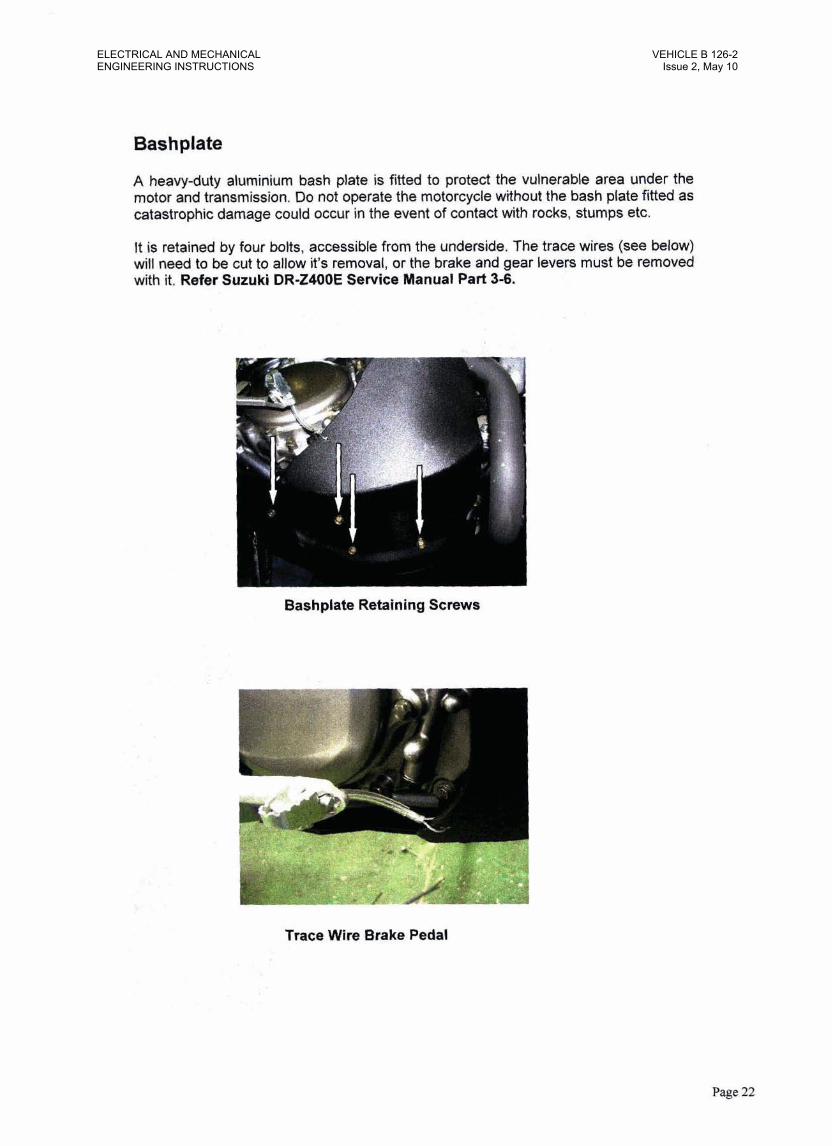
Bashplate
A heavy-duty aluminium bash plate is fitted to protect the vulnerable area under the motor and transmission. Do not operate the motorcycle without the bash plate fitted as catastrophic damage could occur in the event of contact with rocks, stumps etc.
It is retained by faur bolts, accessible from the underside. The trace wires (see below) will need to be cut to allow it's removal, or the brake and gear levers must be removed with it. Refer Suzuki DR-Z4OOE Service Manual Part 3-6.
. 1 4 +,, 4.
Y_, - Bashplate Retaining Screws
Trace Wire Brake Pedal
Page 22
ELECTRICAL AND MECHANICALENGINEERING INSTRUCTIONS
VEHICLE B 126-2Issue 2, May 10

Trace Wires
Trace wires are fitted to the PMC-SF between the rear brake pedal and bash plate and between the gear lever and bash plate to prevent sticks etc becoming lodged in the gap between the pedals and frame.
Trace Wire Brake Pedal - ,- 2 .$,.a . f race Wire Gear Peaa~
The trace wires must be cut if the brake pedal, gear lever or bash plates are removed. Replacement with new trace wires will then be required. To fit new trace wires:
%& * , L \ ~ ~ V - . $ . . 2 . h -A .
Insert trace wire through the hole in the pedal. Feed plastic sleeve (approx 50mm long) over wire, followed by crimp ferrule. Pass wire through hole in bash plate. The trace wire assembly must be long enough to allow full travel of brake pedal and gear lever.
+&:L Return the free end of the wire back throuah the crimp ferrule. Ensure that the plastic sleevgabuts hard against the inside of the lever and the ferrule abuts hard against the plastic sleeve. Any a I ~ k could allow the nipple to protrude and foul against the outer edge of the pedal. This could im~ede , -
gear selection.
Crimp ferrule with crimping tool and cut off excess wire with side cutters.
Page 23
VEHICLE B 126-2Issue 2, May 10
ELECTRICAL AND MECHANICALENGINEERING INSTRUCTIONS

Tank & Seat Covers
Tank and seat covers manufactured from DCPM have been fitted to the PMC-SF. These can be removed and replaced as required.
Seat Cover
Remove the seat as detailed in Suzuki DR-Z400E Service Manual Part 6-2. Undo the Velcro strap and drawstring and peel the old cover off the seat. Replacement procedure is as follows.
- 7 "
I".<
- - - -1
Turn the seat upside down. Place heel of seat into recess at drawstring end of cover.
Stretch cover forward and pull the leading edge over the front of the seat.
I Velcro Stra~s 1 6'
Stretch the cover down over the seat and fasten Velcro straps. Pull drawstring tight and tie off.
Tank Cover - I D Litre fuel tank (Refer Page 16 for Tank Cover - 16 litre tank)
Remove the petrol tank as detailed in Suzuki DR-24OOE Service Manual Part 4-2. Untie or cut the drawstring and peel back the inner flaps of the cover, Pull it over the tank well opposite the fuel tap. Lift it over the seat securing bracket and pull it over the neck of the fuel filler. It can then be drawn over the fuel tap. Replacement procedure is as follows.
Fuel Tap n Turn tank upside down. Place aperture in cover ; over the fuel tap.
Page 24
ELECTRICAL AND MECHANICALENGINEERING INSTRUCTIONS
VEHICLE B 126-2Issue 2, May 10

Tank & Seat Covers (continued)
Turn tank over. Pull the cover over the fuel filler neck and seat securing bracket. Stretch the cover tightly over the tank and slip it over the tank well opposite the fuel tap
Turn the tank upside down again. Pull flaps of the cover over the tank mounting brackets, pull the drawstring tight and tie off.
, 'W
Tuck the excess string inside the cover.
Fuel Filler Neck e
Page 25
VEHICLE B 126-2Issue 2, May 10
ELECTRICAL AND MECHANICALENGINEERING INSTRUCTIONS
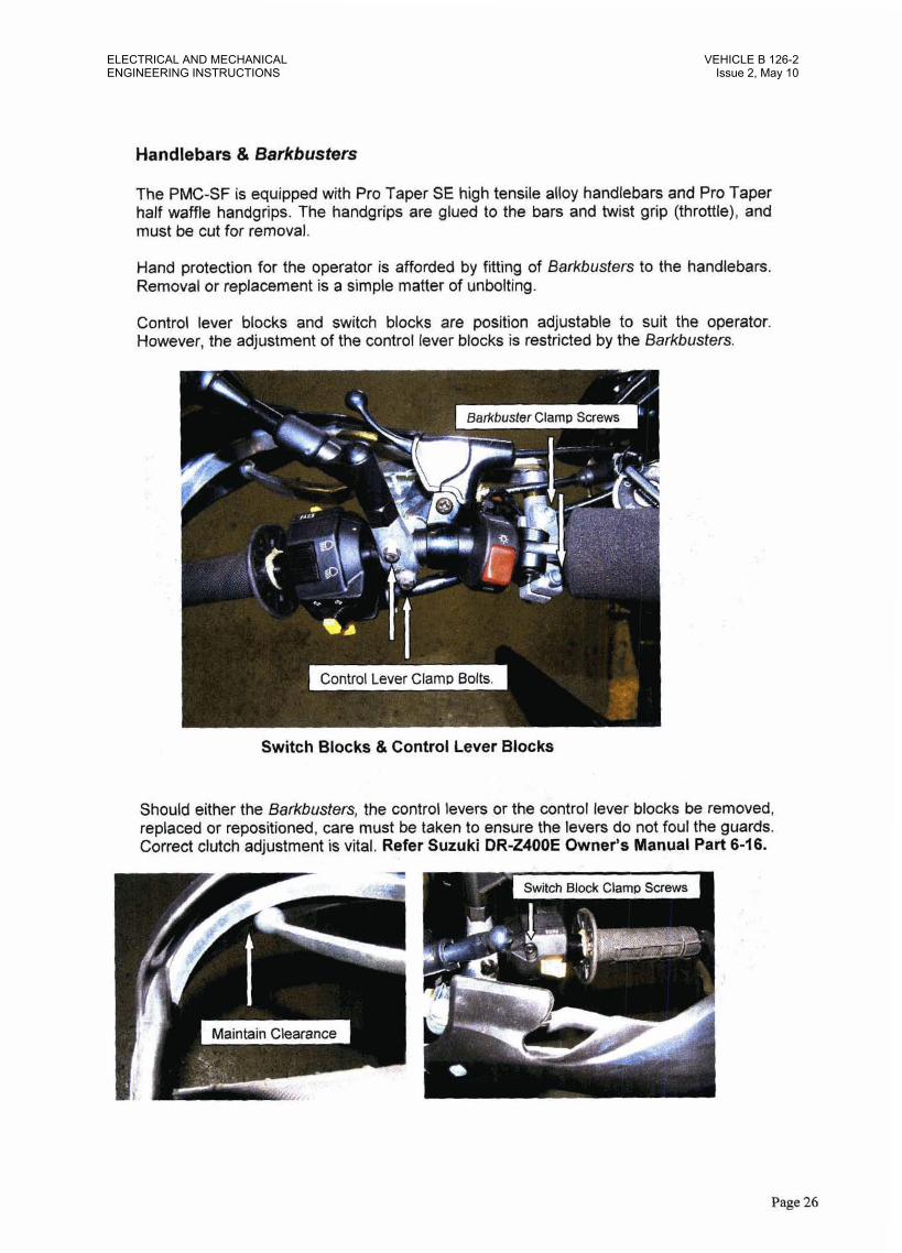
Handlebars & Barkbusters
The PMC-SF is equipped with Pro Taper SE high tensile alloy handlebars and Pro Taper half waffle handgrips. The handgrips are glued to the bars and twist grip (throWe), and must be cut for removal.
Hand protection for the operator is afforded by Mting of Barkbusters to the handlebars. Removal or replacement is a simple matter of unbolting.
Control lever blocks and switch blocks are position adjustable to suit the operator. However, the adjustment of the control lever blocks is restricted by the Barkbbusters.
Switch Blocks & Control Lever Blocks
Should either the Bsrkbusfers, the control levers or the control lever blocks be removed, replaced or repositioned, care must be taken to ensure the levers do not foul the guards. Correct clutch adjustment is vital. Refer Suzuki DR-UOOE Owner's Manual Part 6-16.
Maintain Clearance
Page 26
ELECTRICAL AND MECHANICALENGINEERING INSTRUCTIONS
VEHICLE B 126-2Issue 2, May 10

Front Disc Protector - Acerbis (Obsolete - Replace with Part No BDI 15642)
The Front Brake Disc Protector (Fig 1.) fitted to the PMC-SF IS an Acerbis brand part. It is a universal type and the mounting brackets are custom made to suit the DR-Z400E.
Removal and replacement is a simple matter of undoing the two mounting screws.
Should the brackets be removed or replaced they must be carefully positioned before their retaining bolts are tightened. Loosely assemble the brackets on the lower fork leg. (Fig 2.) Tighten the bolts sufficiently to offer some resistance to rotational movement of the brackets. Offer the protector to the brackets and ensure the holes in the disc protector align with the holes in the mounting brackets (Fig 3.) and that the circumference of the disc protector is concentric to the brake disc (Fig 4.). Adjust brackets as necessary. Remove the disc protector and tighten the bracket retaining bolts. Fit the disc protector and tighten the mounting screws.
- 3 7 +I,. '& 7 .
Fig I. Front Disc Protector
f~ Align Mountlrg Holes
Fig 3. Offering Disc Protector to Mounting Brackets
, .- \..
Fig 2. Front Disc Protector Mounting Brackets
Flg 4. Check Concentricity to DISC
Page 27
- -
VEHICLE B 126-2Issue 2, May 10
ELECTRICAL AND MECHANICALENGINEERING INSTRUCTIONS
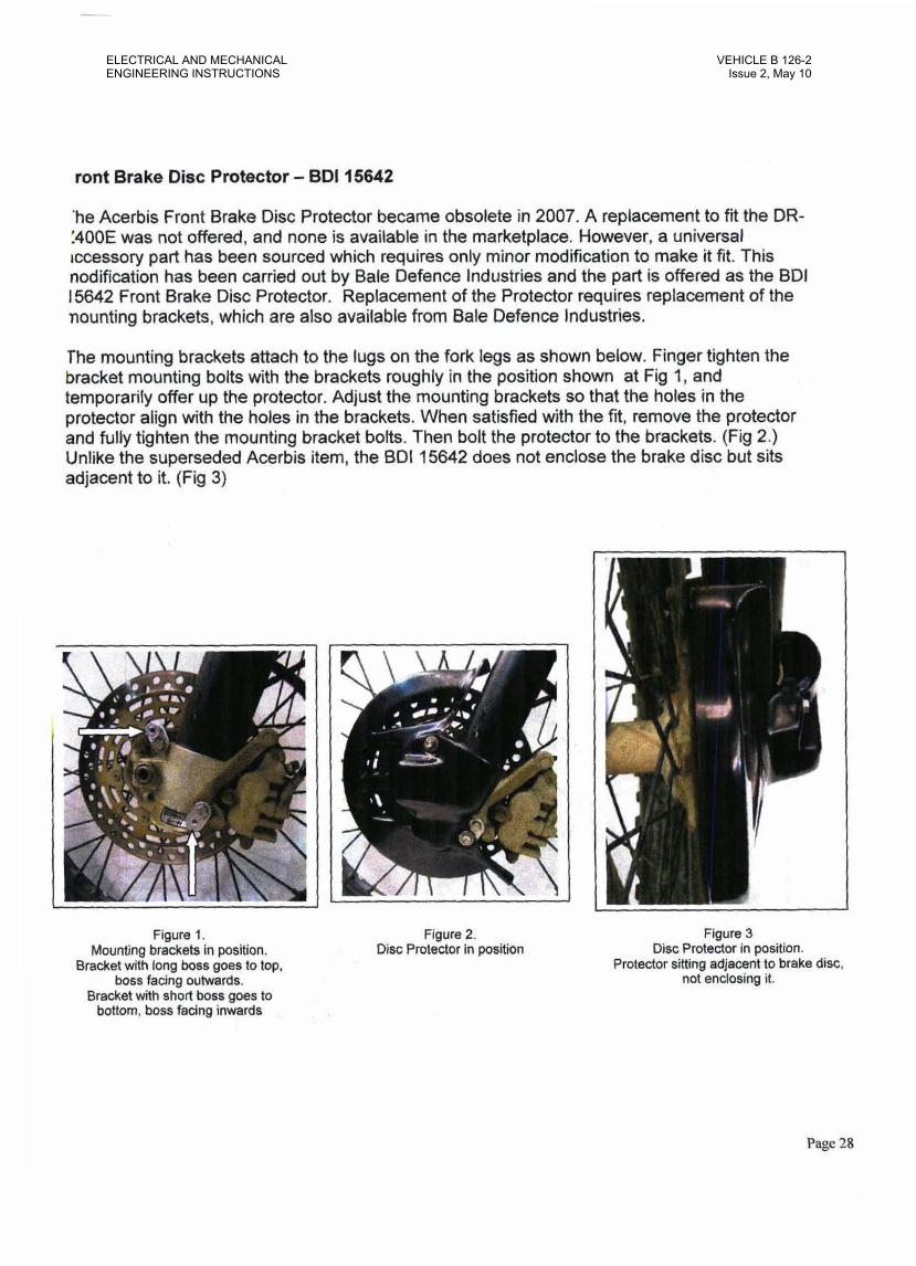
tont Brake Disc Protector - BDI 15642
'he Acerbis Front Brake Disc Protector became obsolete in 2007. A replacement to fit the DR- /400E was not offered, and none is available in the marketplace. However, a universal tccessory part has been sourced which requires only minor modification to make it fit. This nodification has been carried out by Bale Defence Industries and the part is offered as the BDI 15642 Front Brake Disc Protector. Replacement of the Protector requires replacement of the mounting brackets, which are also available from Bele Defence Industries.
The mounting brackets attach to the lugs on the fork legs as shown below. Finger tighten the bracket mounting bolts with the brackets roughly in the position shown at Fig 1, end temporarily offer up the protector. Adjust the mounting brackets so that the holes in the protector align with the holes in the brackets. When satisfied with the fit, remove the protector and fully tighten the mounting bracket bolts. Then bolt the protector to the brackets. (Fig 2.) Unlike the superseded Acerbis item, the BDI 15642 does not enclose the brake disc but sits adjacent to it. (Fig 3)
Figure I. Mounting brackets in position.
Bracket with long boss goes to top, boss facing outwards.
Bracket with short boss goes to bottom, boss facing inwards
Figure 2. Disc Protector in position
Figure 3 Disc Protector in position.
Protector sitting adjacent to brake disc, not enclosing it.
Page 28
ELECTRICAL AND MECHANICALENGINEERING INSTRUCTIONS
VEHICLE B 126-2Issue 2, May 10

Kick Starter d:r'
An auxiliary kick stalter kit has been fitted to the PMC-SF. It is an OEM part.
Rekr to Suzuki DR-24OOE Service Manual
. . . . . .
Black Vinyl Adhesive Sheet .I . -I - . . 1 . . t - . ! - # a q ' .
. . ..I
Black vinyl ldhesiv8 sheet has been fitted to the swing arm and forks of the PMC-SF to disguise reflective areas of the machine. . 9 '
1 . : I . , J . . C '
If forks are removed from the triple clamps, the sheeting muit be removed 6wf to allow the fork legs to drop through the lower clamp. if one edge is liffed with a knife or screwdriver the vinyl will peel off
The product is reif-adhesive. To replace, ensure the surface is pedectly clean by wiping with solvent. Peel the backing from the vinyl sheet and carefully align one edge Wrap it smund the foh w o l n g out anv air bubbles with e small straight edge as you go.
Fork Legs w. Swing Arm
VEHICLE B 126-2Issue 2, May 10
ELECTRICAL AND MECHANICALENGINEERING INSTRUCTIONS
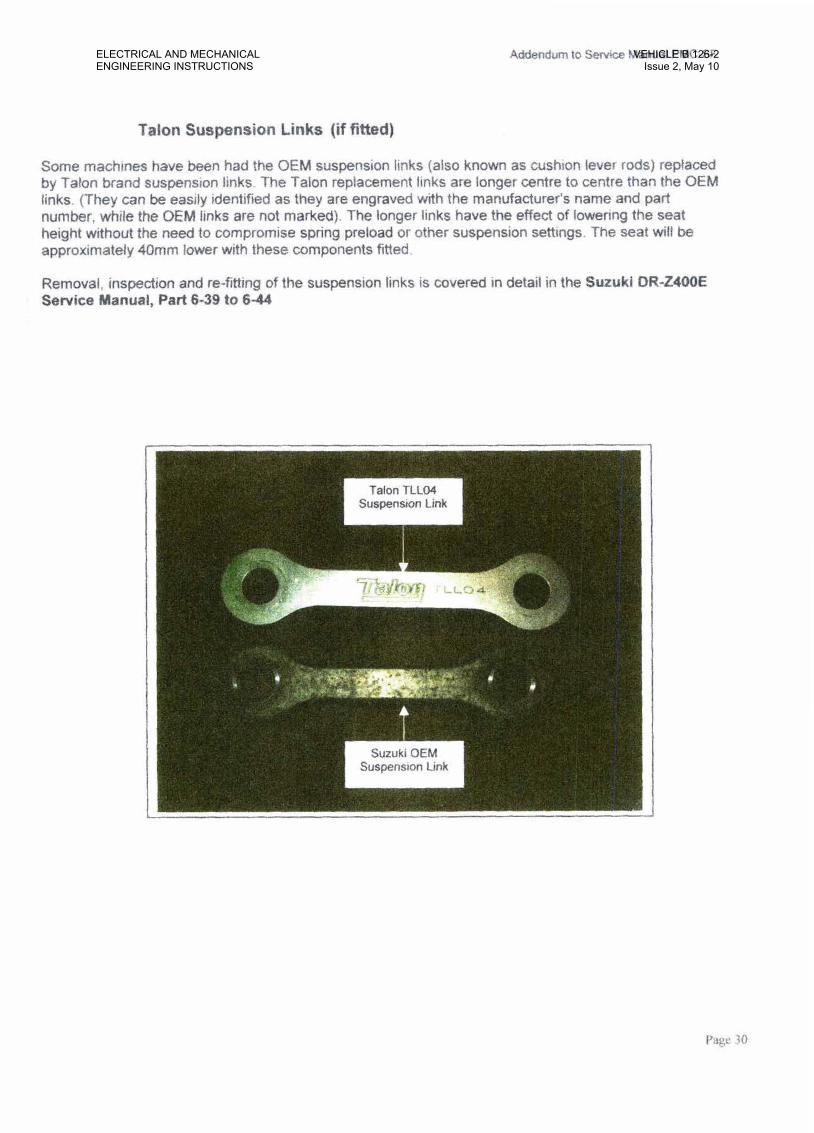
Talon Suspension Links (if fitted)
Some machines have k e n had the OEM suspension links (also known as cushion lever rods) replaced by Talon brand suspension links. The Talon replacement links are longer centre to centre Man the OEM links. ( T h y can be easily identified as they are engraved with the manufacturer's Rame and par! number, while the OEM links are not marked). The longer links have the effbct of her ing the seat height without the need to compromise spring preload w other suspens~on settings. The seat will be approximately 40mm lower with these components frtted.
Removal, inspection and re-fitting of the suspension links is awered in detail in the Suzuki DR-UOOE Sewice Manual, Part 6-39 to 6-44
Suzuki OEM Suspension Link
Page 30
ELECTRICAL AND MECHANICALENGINEERING INSTRUCTIONS
VEHICLE B 126-2Issue 2, May 10
Produccd by Bale Ekfence Industries Pty I.,td 15- 1 7 Jindalee Rd, Port Macquaric, NS W 2444
1 5th March 2010
VEHICLE B 126-2Issue 2, May 10
ELECTRICAL AND MECHANICALENGINEERING INSTRUCTIONS