pmbus™ commands application note murata … commands application note murata digital power brick...
TRANSCRIPT
MDC-AN-67 08 December 2016
PMBus™ Commands Application Note
Murata Digital Power Brick
Murata Digital Power Brick PMBus™ Commands Application Note
08 December 2016 MDC-AN-67 Page 2 of 48
www.murata-ps.com
www.murata-ps.com/support
ContentsAbstract ......................................................................................... 3Introduction ................................................................................... 3PMBus™ Commands .................................................................... 31. Overall List ................................................................................. 32. Commands application .............................................................. 5
OPERATION (01h) ....................................................................... 5ON_OFF_CONFIG (02h) .............................................................. 6CLEAR_FAULTS (03h) ................................................................. 6WRITE_PROTECT (10h) .............................................................. 7STORE_DEFAULT_ALL (11h) ....................................................... 7RESTORE_DEFAULT_ALL (12h) ................................................... 7STORE_USER_ALL (15h) ............................................................ 8RESTORE_USER_ALL (16h) ........................................................ 8CAPABILITY (19h) ....................................................................... 8VOUT_MODE (20h) ..................................................................... 9VOUT_COMMAND (21h) ............................................................. 9VOUT_TRIM (22h) ....................................................................... 9VOUT_MARGIN_HIGH (25h) ...................................................... 10VOUT_MARGIN_LOW (26h) ....................................................... 10VOUT_DROOP (28h) ................................................................. 11VOUT_OV_FAULT_LIMIT (40h) .................................................. 11VOUT_OV_FAULT_RESPONSE (41h) .......................................... 12VOUT_OV_WARN_LIMIT (42h) .................................................. 13VOUT_UV_WARN_LIMIT (43h) .................................................. 13VOUT_UV_FAULT_LIMIT (44h)................................................... 14IOUT_OC_FAULT_LIMIT (46h) ................................................... 14IOUT_OC_FAULT_RESPONSE (47h) ........................................... 15IOUT_OC_WARN_LIMIT (4Ah) ................................................... 16OT_FAULT_LIMIT (4Fh) ............................................................. 17OT_FAULT_RESPONSE (50h) .................................................... 17OT_WARN_LIMIT (51h)............................................................. 18VIN_OV_FAULT_LIMIT (55h) ...................................................... 19VIN_OV_FAULT_RESPONSE (56h) ............................................. 20VIN_OV_WARN_LIMIT (57h) ..................................................... 20VIN_UV_WARN_LIMIT (58h)...................................................... 21VIN_UV_FAULT_LIMIT (59h) ...................................................... 22VIN_UV_FAULT_RESPONSE (5Ah) ............................................. 22POWER_GOOD_ON (5Eh).......................................................... 23POWER_GOOD_OFF (5Fh) ........................................................ 24TON_DELAY (60h) .................................................................... 24TON_RISE (61h) ....................................................................... 25TOFF_DELAY (64h) ................................................................... 25TOFF_FALL (65h) ..................................................................... 26STATUS_BYTE (78h) ................................................................. 26STATUS_WORD (79h) ............................................................... 27
STATUS_VOUT (7Ah)................................................................. 28STATUS_IOUT (7Bh).................................................................. 29STATUS_INPUT (7Ch)................................................................ 30STATUS_TEMPERATURE (7Dh) .................................................. 30STATUS_CML (7Eh) .................................................................. 31READ_VIN (88h) ....................................................................... 32READ_VOUT (8Bh) .................................................................... 32READ_IOUT (8Ch) ..................................................................... 33READ_TEMPERATURE_1 (8Dh) ................................................. 33READ_TEMPERATURE_2 (8Eh) ................................................. 34READ_DUTY_CYCLE (94h) ........................................................ 34READ_FREQUENCY (95h).......................................................... 35READ_POUT (96h) .................................................................... 35PMBus_REVISION (98h) ............................................................ 36MFR_ID (99h) ........................................................................... 36MFR_MODEL (9Ah) .................................................................. 36MFR_REVISION (9Bh) ............................................................... 37MFR_LOCATION (9Ch) .............................................................. 37MFR_DATE (9Dh) ..................................................................... 37MFR_SERIAL (9Eh) ................................................................... 37MFR_VIN_MIN (A0h) ................................................................ 38MFR_VIN_MAX (A1h) ................................................................ 38MFR_IIN_MAX (A2h) ................................................................. 39MFR_PIN_MAX (A3h) ............................................................... 39MFR_VOUT_MIN (A4h) ............................................................. 40MFR_VOUT_MAX (A5h) ............................................................ 40MFR_IOUT_MAX (A6h) ............................................................. 41MFR_POUT_MAX (A7h) ............................................................ 41MFR_TAMBIENT_MAX (A8h) ..................................................... 42MFR_TAMBIENT_MIN (A9h) ...................................................... 42USER_DATA_00 (B0h) .............................................................. 43USER_DATA_01 (B1h) .............................................................. 43MFR_MAX_TEMP_1 (C0h) ........................................................ 43MFR_CURRENT_SHARE_CONFIG (DBh) .................................... 44MFR_PRIMARY_ON_OFF_CONFIG (DDh)................................... 44MFR_PGOOD_POLARITY (DEh) ................................................. 44MFR_VIN_OV_FAULT_HYS (E8h) ............................................... 45MFR_VIN_UV_FAULT_HYS (E9h) ............................................... 45MFR_OT_FAULT_HYS (EAh) ...................................................... 46MFR_CALIBRATION_STATUS (F6h)............................................ 46MFR_VIN_SENSE_CALIBRATION (F9h) ...................................... 47MFR_IOUT_SENSE_CALIBRATION (FAh) .................................... 47MFR_VOUT_SET_POINT_CALIBRATION (FBh) ........................... 48MFR_SUPERVISOR_PASSWORD (FCh) ...................................... 48
Murata Digital Power Brick PMBus™ Commands Application Note
08 December 2016 MDC-AN-67 Page 3 of 48
www.murata-ps.com/support
AbstractThis document provides a detailed application description of each PMBus™ command supported by Murata digital power modules based on PMBus™ specifications. Each command item includes command type, data length, data format, data range, data unit, default value, com-mand definition and register data table. Besides, to get better understanding of data conversion, calculation examples are listed.
IntroductionThe Murata digital power modules are designed to be PMBus™ revision 1.2 compliant. Digital PMBus™ interface allows the module to be configured, and communicate with system controllers. The following PMBus™ commands listed are relevant to DC /DC products and will vary with different module types. More Detailed PMBus™ information can refer to“PMBus™ Power System Management Protocol Specifica-tion, Part I – General Requirements, Transport and Electrical Interface” and “PMBus™ Power System Management Protocol, Part II – Com-mand Language”, available at http://pmbus.org.
PMBus™ Commands
1. Overall List
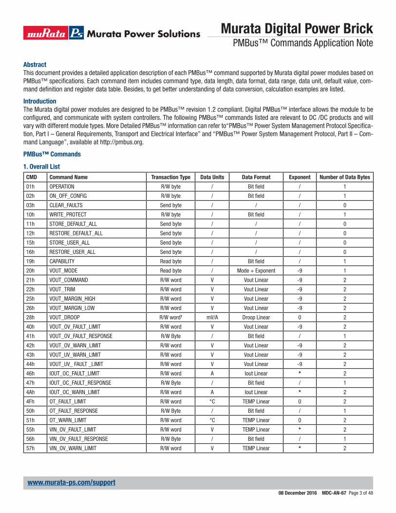
CMD Command Name Transaction Type Data Units Data Format Exponent Number of Data Bytes
01h OPERATION R/W byte / Bit field / 1
02h ON_OFF_CONFIG R/W byte / Bit field / 1
03h CLEAR_FAULTS Send byte / / / 0
10h WRITE_PROTECT R/W byte / Bit field / 1
11h STORE_DEFAULT_ALL Send byte / / / 0
12h RESTORE_DEFAULT_ALL Send byte / / / 0
15h STORE_USER_ALL Send byte / / / 0
16h RESTORE_USER_ALL Send byte / / / 0
19h CAPABILITY Read byte / Bit field / 1
20h VOUT_MODE Read byte / Mode + Exponent -9 1
21h VOUT_COMMAND R/W word V Vout Linear -9 2
22h VOUT_TRIM R/W word V Vout Linear -9 2
25h VOUT_MARGIN_HIGH R/W word V Vout Linear -9 2
26h VOUT_MARGIN_LOW R/W word V Vout Linear -9 2
28h VOUT_DROOP R/W word1 mV/A Droop Linear 0 2
40h VOUT_OV_FAULT_LIMIT R/W word V Vout Linear -9 2
41h VOUT_OV_FAULT_RESPONSE R/W Byte / Bit field / 1
42h VOUT_OV_WARN_LIMIT R/W word V Vout Linear -9 2
43h VOUT_UV_WARN_LIMIT R/W word V Vout Linear -9 2
44h VOUT_UV_ FAULT _LIMIT R/W word V Vout Linear -9 2
46h IOUT_OC_FAULT_LIMIT R/W word A Iout Linear * 2
47h IOUT_OC_FAULT_RESPONSE R/W Byte / Bit field / 1
4Ah IOUT_OC_WARN_LIMIT R/W word A Iout Linear * 2
4Fh OT_FAULT_LIMIT R/W word °C TEMP Linear 0 2
50h OT_FAULT_RESPONSE R/W Byte / Bit field / 1
51h OT_WARN_LIMIT R/W word °C TEMP Linear 0 2
55h VIN_OV_FAULT_LIMIT R/W word V TEMP Linear * 2
56h VIN_OV_FAULT_RESPONSE R/W Byte / Bit field / 1
57h VIN_OV_WARN_LIMIT R/W word V TEMP Linear * 2
Murata Digital Power Brick PMBus™ Commands Application Note
08 December 2016 MDC-AN-67 Page 4 of 48
www.murata-ps.com/support
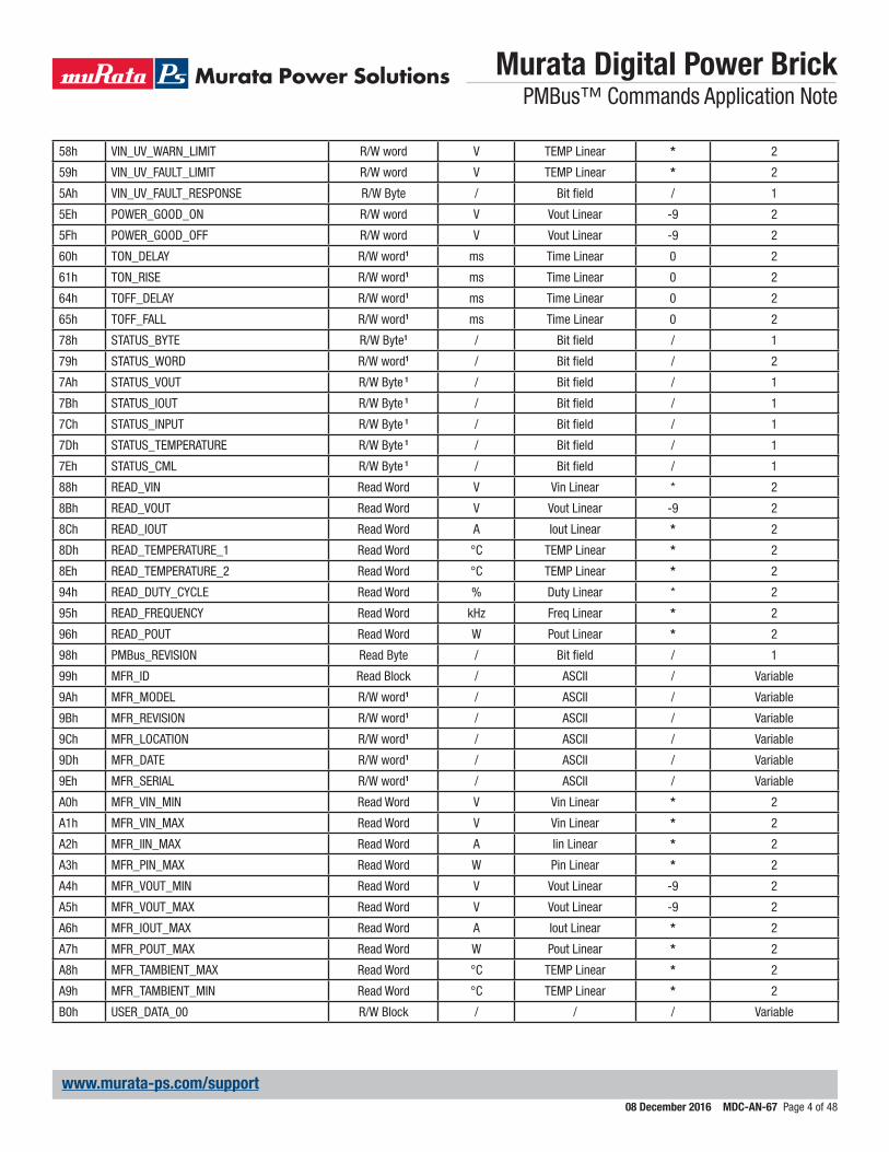
58h VIN_UV_WARN_LIMIT R/W word V TEMP Linear * 2
59h VIN_UV_FAULT_LIMIT R/W word V TEMP Linear * 2
5Ah VIN_UV_FAULT_RESPONSE R/W Byte / Bit field / 1
5Eh POWER_GOOD_ON R/W word V Vout Linear -9 2
5Fh POWER_GOOD_OFF R/W word V Vout Linear -9 2
60h TON_DELAY R/W word1 ms Time Linear 0 2
61h TON_RISE R/W word1 ms Time Linear 0 2
64h TOFF_DELAY R/W word1 ms Time Linear 0 2
65h TOFF_FALL R/W word1 ms Time Linear 0 2
78h STATUS_BYTE R/W Byte1 / Bit field / 1
79h STATUS_WORD R/W word1 / Bit field / 2
7Ah STATUS_VOUT R/W Byte 1 / Bit field / 1
7Bh STATUS_IOUT R/W Byte 1 / Bit field / 1
7Ch STATUS_INPUT R/W Byte 1 / Bit field / 1
7Dh STATUS_TEMPERATURE R/W Byte 1 / Bit field / 1
7Eh STATUS_CML R/W Byte 1 / Bit field / 1
88h READ_VIN Read Word V Vin Linear * 2
8Bh READ_VOUT Read Word V Vout Linear -9 2
8Ch READ_IOUT Read Word A Iout Linear * 2
8Dh READ_TEMPERATURE_1 Read Word °C TEMP Linear * 2
8Eh READ_TEMPERATURE_2 Read Word °C TEMP Linear * 2
94h READ_DUTY_CYCLE Read Word % Duty Linear * 2
95h READ_FREQUENCY Read Word kHz Freq Linear * 2
96h READ_POUT Read Word W Pout Linear * 2
98h PMBus_REVISION Read Byte / Bit field / 1
99h MFR_ID Read Block / ASCII / Variable
9Ah MFR_MODEL R/W word1 / ASCII / Variable
9Bh MFR_REVISION R/W word1 / ASCII / Variable
9Ch MFR_LOCATION R/W word1 / ASCII / Variable
9Dh MFR_DATE R/W word1 / ASCII / Variable
9Eh MFR_SERIAL R/W word1 / ASCII / Variable
A0h MFR_VIN_MIN Read Word V Vin Linear * 2
A1h MFR_VIN_MAX Read Word V Vin Linear * 2
A2h MFR_IIN_MAX Read Word A Iin Linear * 2
A3h MFR_PIN_MAX Read Word W Pin Linear * 2
A4h MFR_VOUT_MIN Read Word V Vout Linear -9 2
A5h MFR_VOUT_MAX Read Word V Vout Linear -9 2
A6h MFR_IOUT_MAX Read Word A Iout Linear * 2
A7h MFR_POUT_MAX Read Word W Pout Linear * 2
A8h MFR_TAMBIENT_MAX Read Word °C TEMP Linear * 2
A9h MFR_TAMBIENT_MIN Read Word °C TEMP Linear * 2
B0h USER_DATA_00 R/W Block / / / Variable
Murata Digital Power Brick PMBus™ Commands Application Note
08 December 2016 MDC-AN-67 Page 5 of 48
www.murata-ps.com/support
B1h USER_DATA_01 R/W Block / / / Variable
C0h MFR_MAX_TEMP_1 Read Word °C TEMP Linear * 2
DBh MFR_CURRENT_SHARE_CONFIG R/W Byte2 / Bit field / 1
DDh MFR_PRIMARY_ON_OFF_CONFIG R/W Byte2 / Bit field / 1
DEh MFR_PGOOD_POLARITY R/W Byte2 / Bit field / 1
E8h MFR_VIN_OV_FAULT_HYS R/W Word2 V Vin Linear * 2
E9h MFR_VIN_UV_FAULT_HYS R/W Word2 V Vin Linear * 2
EAh MFR_OT_FAULT_HYS R/W Word2 °C TEMP Linear 0 2
F6h MFR_CALIBRATION_STATUS Read Byte2 / Bit field / 1
F9h MFR_VIN_SENSE_CALIBRATION Write Byte2 / Bit field / 1
FAh MFR_IOUT_SENSE_CALIBRATION Write Word2 A Iout Linear * 2
FBh MFR_VOUT_SET_POINT_CALIBRATION Write Word2 V Vout Linear -9 2
FCh MFR_SUPERVISOR_PASSWORD Write Block2 / ASCII / Variable
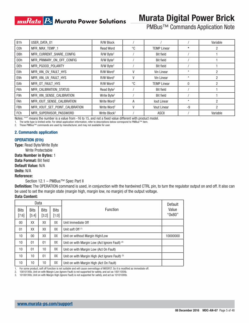
Notes: “*” means the number is a value from -16 to 15, and not a fixed value different with product model.1. The write type is limited write. For detail application information, refer to descriptions below correspond to PMBus™ item.2. Those PMBus™ commands are used by manufacturer, and may not available for user.
2. Commands application
OPERATION (01h)Type: Read Byte/Write Byte
Write ProtectableData Number in Bytes: 1Data Format: Bit fieldDefault Value: N/AUnits: N/AReference:
Section 12.1 – PMBus™ Spec Part IIDefinition: The OPERATION command is used, in conjunction with the hardwired CTRL pin, to turn the regulator output on and off. It also can be used to set the margin state (margin high, margin low, no margin) of the output voltage.Data Content:
Data
FunctionDefault Value
“0x80”Bits [7:6]
Bits [5:4]
Bits [3:2]
Bits [1:0]
00 XX XX XX Unit Immediate Off
01 XX XX XX Unit soft Off (1)
10 00 XX XX Unit on without Margin High/Low 10000000
10 01 01 XX Unit on with Margin Low (Act Ignore Fault) (2)
10 01 10 XX Unit on with Margin Low (Act On Fault)
10 10 01 XX Unit on with Margin High (Act Ignore Fault) (3)
10 10 10 XX Unit on with Margin High (Act On Fault)
1. For some product, soft off function is not suitable and will cause overvoltage of MOSFET. So it is modified as immediate off.2. 100101XXb, Unit on with Margin Low (Ignore Fault) is not supported for safety, and act as 100110XXb.3. 101001XXb, Unit on with Margin High (Ignore Fault) is not supported for safety, and act as 101010XXb.
Murata Digital Power Brick PMBus™ Commands Application Note
08 December 2016 MDC-AN-67 Page 6 of 48
www.murata-ps.com/support
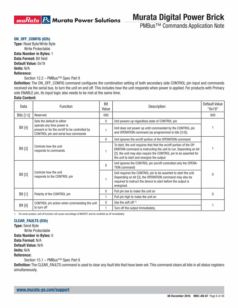
ON_OFF_CONFIG (02h)Type: Read Byte/Write Byte
Write ProtectableData Number in Bytes: 1Data Format: Bit fieldDefault Value: 0x19Units: N/AReference:
Section 12.2 – PMBus™ Spec Part IIDefinition: The ON_OFF_CONFIG command configures the combination setting of both secondary side CONTROL pin input and commands received via the serial bus, to turn the unit on and off. This includes how the unit responds when power is applied. For products with Primary side ENABLE pin, its input logic also needs to be met at the same time.Data Content:
Data FunctionBit
ValueDescription
Default Value “0x19”
Bits [7:5] Reserved 000 000
Bit [4]
Sets the default to eitheroperate any time power ispresent or for the on/off to be controlled by CONTROL pin and serial bus commands
0 Unit powers up regardless state of CONTROL pin
11
Unit does not power up until commanded by the CONTROL pin and OPERATION command (as programmed in bits [3:0]).
Bit [3] Controls how the unitresponds to commands
0 Unit ignores the on/off portion of the OPERATION command
11
To start, the unit requires that that the on/off portion of the OP-ERATION command is instructing the unit to run. Depending on bit [2], the unit may also require the CONTROL pin to be asserted for the unit to start and energize the output
Bit [2] Controls how the unitresponds to the CONTROL pin
0Unit ignores the CONTROL pin (on/off controlled only the OPERA-TION command)
01
Unit requires the CONTROL pin to be asserted to start the unit.Depending on bit [3], the OPERATION command may also be required to instruct the device to start before the output is energized.
Bit [1] Polarity of the CONTROL pin0 Pull pin low to make the unit on
01 Pull pin high to make the unit on
Bit [0] CONTROL pin action when commanding the unit to turn off
0 Use the soft off (1)
11 Turn off the output Immediately.
1. For some product, soft off function will cause overvoltage of MOSFET and be modified as off immediately.
CLEAR_FAULTS (03h)Type: Send Byte
Write ProtectableData Number in Bytes: 0Data Format: N/ADefault Value: N/AUnits: N/AReference:
Section 15.1 – PMBus™ Spec Part IIDefinition: The CLEAR_FAULTS command is used to clear any fault bits that have been set. This command clears all bits in all status registers simultaneously.
Murata Digital Power Brick PMBus™ Commands Application Note
08 December 2016 MDC-AN-67 Page 7 of 48
www.murata-ps.com/support
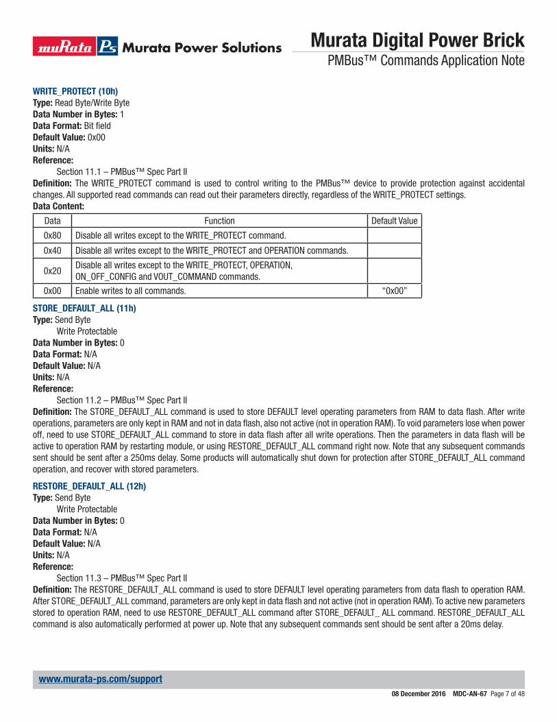
WRITE_PROTECT (10h)Type: Read Byte/Write ByteData Number in Bytes: 1Data Format: Bit fieldDefault Value: 0x00Units: N/AReference:
Section 11.1 – PMBus™ Spec Part IIDefinition: The WRITE_PROTECT command is used to control writing to the PMBus™ device to provide protection against accidental changes. All supported read commands can read out their parameters directly, regardless of the WRITE_PROTECT settings.Data Content:
Data Function Default Value
0x80 Disable all writes except to the WRITE_PROTECT command.
0x40 Disable all writes except to the WRITE_PROTECT and OPERATION commands.
0x20Disable all writes except to the WRITE_PROTECT, OPERATION,ON_OFF_CONFIG and VOUT_COMMAND commands.
0x00 Enable writes to all commands. “0x00”
STORE_DEFAULT_ALL (11h)Type: Send Byte
Write ProtectableData Number in Bytes: 0Data Format: N/ADefault Value: N/AUnits: N/AReference:
Section 11.2 – PMBus™ Spec Part IIDefinition: The STORE_DEFAULT_ALL command is used to store DEFAULT level operating parameters from RAM to data flash. After write operations, parameters are only kept in RAM and not in data flash, also not active (not in operation RAM). To void parameters lose when power off, need to use STORE_DEFAULT_ALL command to store in data flash after all write operations. Then the parameters in data flash will be active to operation RAM by restarting module, or using RESTORE_DEFAULT_ALL command right now. Note that any subsequent commands sent should be sent after a 250ms delay. Some products will automatically shut down for protection after STORE_DEFAULT_ALL command operation, and recover with stored parameters.
RESTORE_DEFAULT_ALL (12h)Type: Send Byte
Write ProtectableData Number in Bytes: 0Data Format: N/ADefault Value: N/AUnits: N/AReference:
Section 11.3 – PMBus™ Spec Part IIDefinition: The RESTORE_DEFAULT_ALL command is used to store DEFAULT level operating parameters from data flash to operation RAM. After STORE_DEFAULT_ALL command, parameters are only kept in data flash and not active (not in operation RAM). To active new parameters stored to operation RAM, need to use RESTORE_DEFAULT_ALL command after STORE_DEFAULT_ ALL command. RESTORE_DEFAULT_ALL command is also automatically performed at power up. Note that any subsequent commands sent should be sent after a 20ms delay.
Murata Digital Power Brick PMBus™ Commands Application Note
08 December 2016 MDC-AN-67 Page 8 of 48
www.murata-ps.com/support
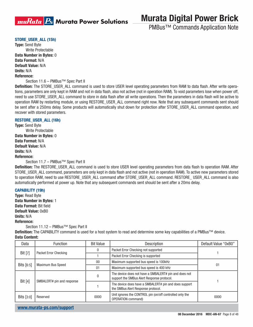
STORE_USER_ALL (15h)Type: Send Byte
Write ProtectableData Number in Bytes: 0Data Format: N/ADefault Value: N/AUnits: N/AReference:
Section 11.6 – PMBus™ Spec Part IIDefinition: The STORE_USER_ALL command is used to store USER level operating parameters from RAM to data flash. After write opera-tions, parameters are only kept in RAM and not in data flash, also not active (not in operation RAM). To void parameters lose when power off, need to use STORE_USER_ALL command to store in data flash after all write operations. Then the parameters in data flash will be active to operation RAM by restarting module, or using RESTORE_USER_ALL command right now. Note that any subsequent commands sent should be sent after a 250ms delay. Some products will automatically shut down for protection after STORE_USER_ALL command operation, and recover with stored parameters.
RESTORE_USER_ALL (16h)Type: Send Byte
Write ProtectableData Number in Bytes: 0Data Format: N/ADefault Value: N/AUnits: N/AReference:
Section 11.7 – PMBus™ Spec Part IIDefinition: The RESTORE_USER_ALL command is used to store USER level operating parameters from data flash to operation RAM. After STORE_USER_ALL command, parameters are only kept in data flash and not active (not in operation RAM). To active new parameters stored to operation RAM, need to use RESTORE_USER_ALL command after STORE_USER_ALL command. RESTORE_ USER_ALL command is also automatically performed at power up. Note that any subsequent commands sent should be sent after a 20ms delay.
CAPABILITY (19h)Type: Read ByteData Number in Bytes: 1Data Format: Bit fieldDefault Value: 0xB0Units: N/AReference:
Section 11.12 – PMBus™ Spec Part IIDefinition: The CAPABILITY command is used for a host system to read and determine some key capabilities of a PMBus™ device.Data Content:
Data Function Bit Value Description Default Value “0xB0”
Bit [7] Packet Error Checking0 Packet Error Checking not supported
11 Packet Error Checking is supported
Bits [6:5] Maximum Bus Speed00 Maximum supported bus speed is 100kHz
0101 Maximum supported bus speed is 400 kHz
Bit [4] SMBALERT# pin and response0
The device does not have a SMBALERT# pin and does not support the SMBus Alert Response protocol.
11
The device does have a SMBALERT# pin and does support the SMBus Alert Response protocol.
Bits [3:0] Reserved 0000Unit ignores the CONTROL pin (on/off controlled only the OPERATION command)
0000
Murata Digital Power Brick PMBus™ Commands Application Note
08 December 2016 MDC-AN-67 Page 9 of 48
www.murata-ps.com/support
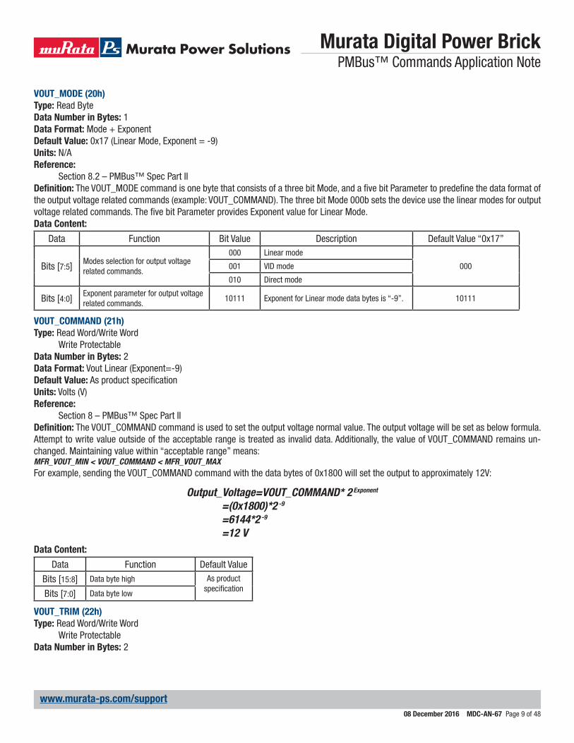
VOUT_MODE (20h)Type: Read ByteData Number in Bytes: 1Data Format: Mode + ExponentDefault Value: 0x17 (Linear Mode, Exponent = -9)Units: N/AReference:
Section 8.2 – PMBus™ Spec Part IIDefinition: The VOUT_MODE command is one byte that consists of a three bit Mode, and a five bit Parameter to predefine the data format of the output voltage related commands (example: VOUT_COMMAND). The three bit Mode 000b sets the device use the linear modes for output voltage related commands. The five bit Parameter provides Exponent value for Linear Mode.Data Content:
Data Function Bit Value Description Default Value “0x17”
Bits [7:5] Modes selection for output voltage related commands.
000 Linear mode
000001 VID mode
010 Direct mode
Bits [4:0] Exponent parameter for output voltage related commands.
10111 Exponent for Linear mode data bytes is “-9”. 10111
VOUT_COMMAND (21h)Type: Read Word/Write Word
Write ProtectableData Number in Bytes: 2Data Format: Vout Linear (Exponent=-9)Default Value: As product specificationUnits: Volts (V)Reference:
Section 8 – PMBus™ Spec Part IIDefinition: The VOUT_COMMAND command is used to set the output voltage normal value. The output voltage will be set as below formula. Attempt to write value outside of the acceptable range is treated as invalid data. Additionally, the value of VOUT_COMMAND remains un-changed. Maintaining value within “acceptable range” means:MFR_VOUT_MIN < VOUT_COMMAND < MFR_VOUT_MAXFor example, sending the VOUT_COMMAND command with the data bytes of 0x1800 will set the output to approximately 12V:
Output_Voltage=VOUT_COMMAND* 2 Exponent
=(0x1800)*2 -9
=6144*2 -9
=12 VData Content:
Data Function Default Value
Bits [15:8] Data byte high As product specificationBits [7:0] Data byte low
VOUT_TRIM (22h)Type: Read Word/Write Word
Write ProtectableData Number in Bytes: 2

Murata Digital Power Brick PMBus™ Commands Application Note
08 December 2016 MDC-AN-67 Page 10 of 48
www.murata-ps.com/support
Data Format: Signed Vout Linear (Exponent=-9)Default Value: 0x0000Units: Volts (V)Reference:
Section 8.3 – PMBus™ Spec Part IISection 13.3 – PMBus™ Spec Part II
Definition: The VOUT_TRIM command is used to apply a fixed offset voltage to trim up/down the output voltage command value. The two bytes are formatted as a two’s complement binary mantissa, used in conjunction with the exponent set in VOUT_MODE as VOUT_COMMAND. The trim voltage will be set as below formula. Attempt to write value outside of the acceptable range is treated as invalid data. Additionally, the value of VOUT_TRIM remains unchanged. Maintaining value within “acceptable range” means:MFR_VOUT_MIN < VOUT_TRIM+VOUT_COMMAND < MFR_VOUT_MAXFor example, sending the VOUT_TRIM command with the data bytes of 0x0100 will trim up the output to approximately 0.5V:
Trim_Voltage=VOUT_TRIM* 2 Exponent
=(0x0100)*2 -9
=256*2 -9
=0.5 VData Content:
Data Function Default Value “0x0000”
Bits [15:8] Data byte high 00000000
Bits [7:0] Data byte low 00000000
VOUT_MARGIN_HIGH (25h)Type: Read Word/Write Word
Write ProtectableData Number in Bytes: 2Data Format: Vout Linear (Exponent=-9)Default Value: As product specificationUnits: Volts (V)Reference:
Section 8.3 – PMBus™ Spec Part IISection 13.6 – PMBus™ Spec Part II
Definition: The VOUT_MARGIN_HIGH command is used to set the output voltage value for margin high operation. To enable the operation to output margin high, please refer to the OPERATION command. The margin high voltage will be set as below formula. Attempt to write value outside of the product specification range is treated as invalid data. Additionally, the value of VOUT_MARGIN_HIGH remains unchanged.For example, sending the VOUT_MARGIN_HIGH command with the data bytes of 0x1A00 will change the output to approximately 13V:
Margin_High_Voltage=VOUT_MARGIN_HIGH* 2 Exponent
=(0x1A00)*2 -9
=6656*2 -9
=13 VData Content:
Data Function Default Value
Bits [15:8] Data byte high As product specificationBits [7:0] Data byte low
VOUT_MARGIN_LOW (26h)Type: Read Word/Write Word
Write Protectable
Murata Digital Power Brick PMBus™ Commands Application Note
08 December 2016 MDC-AN-67 Page 11 of 48
www.murata-ps.com/support
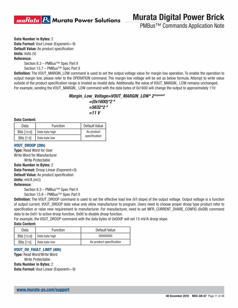
Data Number in Bytes: 2Data Format: Vout Linear (Exponent=-9)Default Value: As product specificationUnits: Volts (V)Reference:
Section 8.3 – PMBus™ Spec Part IISection 13.7 – PMBus™ Spec Part II
Definition: The VOUT_MARGIN_LOW command is used to set the output voltage value for margin low operation. To enable the operation to output margin low, please refer to the OPERATION command. The margin low voltage will be set as below formula. Attempt to write value outside of the product specification range is treated as invalid data. Additionally, the value of VOUT_MARGIN_ LOW remains unchanged.For example, sending the VOUT_MARGIN_ LOW command with the data bytes of 0x1600 will change the output to approximately 11V:
Margin_Low_Voltage=VOUT_MARGIN_LOW* 2 Exponent
=(0x1600)*2 -9
=5632*2 -9
=11 VData Content:
Data Function Default Value
Bits [15:8] Data byte high As product specificationBits [7:0] Data byte low
VOUT_DROOP (28h)Type: Read Word for UserWrite Word for Manufacturer
Write ProtectableData Number in Bytes: 2Data Format: Droop Linear (Exponent=0)Default Value: As product specificationUnits: mV/A (mΩ)Reference:
Section 8.3 – PMBus™ Spec Part IISection 13.9 – PMBus™ Spec Part II
Definition: The VOUT_DROOP command is used to set the effective load line (V/I slope) of the output voltage. Output voltage is a function of output current. VOUT_DROOP data value only allow manufacturer to program. Users need to choose proper droop type product refer to specification or raise new requirement to manufacturer. For manufacturer, need to set MFR_CURRENT_SHARE_CONFIG (0xDB) command data to be 0x01 to active droop function, 0x00 to disable droop function.For example, the VOUT_DROOP command with the data bytes of 0x000F will set 15 mV/A droop slope.Data Content:
Data Function Default Value
Bits [15:8] Data byte high 00000000
Bits [7:0] Data byte low As product specification
VOUT_OV_FAULT_LIMIT (40h)Type: Read Word/Write Word
Write ProtectableData Number in Bytes: 2Data Format: Vout Linear (Exponent=-9)

Murata Digital Power Brick PMBus™ Commands Application Note
08 December 2016 MDC-AN-67 Page 12 of 48
www.murata-ps.com/support
Default Value: As product specificationUnits: Volts (V)Reference:
Section 8.3 – PMBus™ Spec Part IISection 15.2 – PMBus™ Spec Part II
Definition: The VOUT_OV_FAULT_LIMIT command is used to set the output overvoltage fault threshold. The threshold voltage will be set as below formula. Attempt to write value outside of the acceptable range is treated as invalid data. Additionally, the value of VOUT_OV_FAULT_LIMIT remains unchanged. Maintaining value within “acceptable range” means:VOUT_OV_WARN_LIMIT < VOUT_OV_FAULT_LIMIT < Maximum clamp limit (Default in Specification)For example, sending the VOUT_OV_FAULT_LIMIT command with the data bytes of 0x1CCC will change the threshold voltage to approxi-mately 14.4V:
OV_Fault_Voltage=VOUT_OV_FAULT_LIMIT* 2 Exponent
=(0x1CCC)*2 -9
=7372*2 -9
=14.4 VData Content:
Data Function Default Value
Bits [15:8] Data byte high As product specificationBits [7:0] Data byte low
VOUT_OV_FAULT_RESPONSE (41h)Type: Read Byte /Write Byte
Write ProtectableData Number in Bytes: 1Data Format: Bit fieldDefault Value: 0xB8Units: N/AReference:
Section 10.5.1 – PMBus™ Spec Part IISection 15.3 – PMBus™ Spec Part II
Definition: The VOUT_OV_FAULT_ RESPONSE command is used to instruct the device on what action to take in response to an output overvoltage fault. Note that for slowly trigger fault, continuous operation function (Bits [7:6] is 00/01) can be active. But for fast trigger fault, continuous operation function cannot be active. For fast trigger fault, unit will always shut down immediately to protect unit from damage.Data Content:
Data Function Bit Value Description Default Value “0xB8”
Bits [7:6] Response
00 Continuous operation (Ignore fault).
10
01
continues operation for the delay timespecified by bits [2:0] and the delaytime unit specified for that particular fault. If the fault condition is still present at the end of the delay time, the unit responds as programmed in the Retry Setting (bits [5:3]).
10Shutdown (disables the output) and responds according to the retry setting in bits [5:3].
11Shutdown (disables the output) while the fault is present. Opera-tion resumes and the output is enabled when the fault condition no longer exists.
Murata Digital Power Brick PMBus™ Commands Application Note
08 December 2016 MDC-AN-67 Page 13 of 48
www.murata-ps.com/support
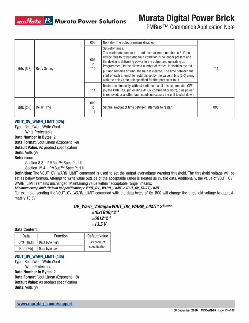
Bits [5:3] Retry Setting
000 No Retry. The output remains disabled.
111
001to
110
Set retry times.The minimum number is 1 and the maximum number is 6. If the device fails to restart (the fault condition is no longer present and the device is delivering power to the output and operating asProgrammed ) in the allowed number of retries, it disables the out-put and remains off until the fault is cleared. The time between the start of each attempt to restart is set by the value in bits [2:0] along with the delay time unit specified for that particular fault.
111Restart continuously, without limitation, until it is commanded OFF (by the CONTROL pin or OPERATION command or both), bias power is removed, or another fault condition causes the unit to shut down.
Bits [2:0] Delay Time000to
111Set the amount of time between attempts to restart. 000
VOUT_OV_WARN_LIMIT (42h)Type: Read Word/Write Word
Write ProtectableData Number in Bytes: 2Data Format: Vout Linear (Exponent=-9)Default Value: As product specificationUnits: Volts (V)Reference:
Section 8.3 – PMBus™ Spec Part IISection 15.4 – PMBus™ Spec Part II
Definition: The VOUT_OV_WARN_LIMIT command is used to set the output overvoltage warning threshold. The threshold voltage will be set as below formula. Attempt to write value outside of the acceptable range is treated as invalid data. Additionally, the value of VOUT_OV_WARN_LIMIT remains unchanged. Maintaining value within “acceptable range” means:Minimum clamp limit (Default in Specification)< VOUT_OV_ WARN _LIMIT < VOUT_OV_FAULT_LIMITFor example, sending the VOUT_OV_WARN_LIMIT command with the data bytes of 0x1B00 will change the threshold voltage to approxi-mately 13.5V:
OV_Warn_Voltage=VOUT_OV_WARN_LIMIT* 2 Exponent
=(0x1B00)*2 -9
=6912*2 -9
=13.5 VData Content:
Data Function Default Value
Bits [15:8] Data byte high As product specificationBits [7:0] Data byte low
VOUT_UV_WARN_LIMIT (43h)Type: Read Word/Write Word
Write ProtectableData Number in Bytes: 2Data Format: Vout Linear (Exponent=-9)Default Value: As product specificationUnits: Volts (V)

Murata Digital Power Brick PMBus™ Commands Application Note
08 December 2016 MDC-AN-67 Page 14 of 48
www.murata-ps.com/support
Reference:Section 8.3 – PMBus™ Spec Part IISection 15.5 – PMBus™ Spec Part II
Definition: The VOUT_OV_WARN_LIMIT command is used to set the output under voltage warning threshold. The threshold voltage will be set as below formula.For example, sending the VOUT_UV_WARN_LIMIT command with the data bytes of 0x1200 will change the threshold voltage to approxi-mately 9.0V:
UV_Warn_Voltage=VOUT_UV_WARN_LIMIT* 2 Exponent
=(0x1200)*2 -9
=4608*2 -9
=9.0 VData Content:
Data Function Default Value
Bits [15:8] Data byte high As product specificationBits [7:0] Data byte low
VOUT_UV_FAULT_LIMIT (44h)Type: Read Word/Write Word
Write ProtectableData Number in Bytes: 2Data Format: Vout Linear (Exponent=-9)Default Value: As product specificationUnits: Volts (V)Reference:
Section 8.3 – PMBus™ Spec Part IISection 15.6 – PMBus™ Spec Part II
Definition: The VOUT_UV_FAULT_LIMIT command is used to set the output under voltage fault threshold. The threshold voltage will be set as below formula.For example, sending the VOUT_UV_FAULT_LIMIT command with the data bytes of 0x1000 will change the threshold voltage to approximately 8.0V:
UV_Fault_Voltage=VOUT_UV_FAULT_LIMIT* 2 Exponent
=(0x1000)*2 -9
=4096*2 -9
=8.0 VData Content:
Data Function Default Value
Bits [15:8] Data byte high As product specificationBits [7:0] Data byte low
IOUT_OC_FAULT_LIMIT (46h)Type: Read Word/Write Word
Write ProtectableData Number in Bytes: 2Data Format: Iout Linear
(Exponent is not fixed, range from -16 to 15)Default Value: As product specification

Murata Digital Power Brick PMBus™ Commands Application Note
08 December 2016 MDC-AN-67 Page 15 of 48
www.murata-ps.com/support
Units: Amperes (A)Reference:
Section 7.1 – PMBus™ Spec Part IISection 15.8 – PMBus™ Spec Part II
Definition: The IOUT_OC_FAULT_LIMIT command is used to set the the output overcurrent fault threshold. The threshold current will be set as below formula. Attempt to write value outside of the acceptable range is treated as invalid data. Additionally, the value of IOUT_OC_FAULT_LIMIT remains unchanged. Maintaining value within “acceptable range” means:IOUT_OC_WARN_LIMIT <IOUT_OC_FAULT_LIMIT < Maximum clamp limit (Default in Specification)For example, sending the IOUT_OC_FAULT_LIMIT command with the data bytes of 0xE320 (Exponent=11100b, Mantissa=01100100000b) will change the threshold current to approximately 50.0A:
OC_Fault_Current=Mantissa* 2 Exponent
=(01100100000b)*2 (11100b)
=(800)*2 -4
=50.0 ANote that for inverse calculation to write right data, exponent value selected should not result in data overflow of the whole linear data.Data Content:
Data Function Default Value
Bits [15:11] Exponent (scaling factor), a 5 bits two’s complement As product
specificationBits [10:0] Mantissa,
a 11 bits two’s complement
IOUT_OC_FAULT_RESPONSE (47h)Type: Read Byte /Write Byte
Write ProtectableData Number in Bytes: 1Data Format: Bit fieldDefault Value: 0xB8Units: N/AReference:
Section 10.5.2 – PMBus™ Spec Part IISection 15.9 – PMBus™ Spec Part II
Definition: The IOUT_OC_FAULT_ RESPONSE command is used to instruct the device on what action to take in response to an output overcurrent fault. Note that for slowly trigger fault, continuous operation function (Bits [7:6] is 00/01) can be active. But for fast trigger fault, continuous operation function cannot be active. For fast trigger fault, unit will always shut down immediately to protect unit from damage.Data Content:
Data Function Bit Value Description Default Value “0xB8”
Bits [7:6] Response
00 Continuous operation (Ignore fault).
10
01Continues operation and responds according to the retry setting in bits [5:3].
10
Continues operation for the delay timespecified by bits [2:0] and the delaytime unit specified for that particularfault. If the fault condition is still present at the end of the delay time, the unit responds as programmed in the Retry Setting (bits [5:3]).
11shutdown (disables the output) and responds according to the retry setting in bits [5:3].
Murata Digital Power Brick PMBus™ Commands Application Note
08 December 2016 MDC-AN-67 Page 16 of 48
www.murata-ps.com/support
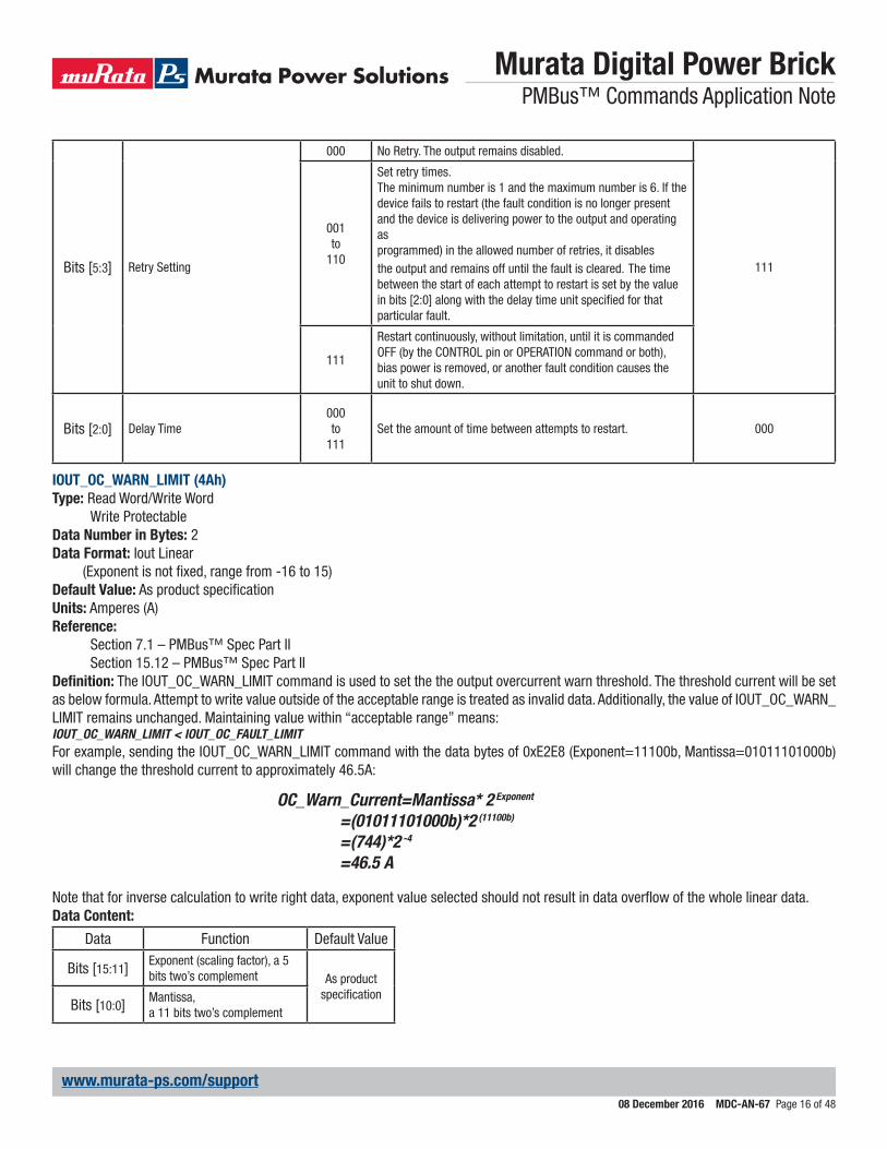
Bits [5:3] Retry Setting
000 No Retry. The output remains disabled.
111
001to
110
Set retry times.The minimum number is 1 and the maximum number is 6. If the device fails to restart (the fault condition is no longer present and the device is delivering power to the output and operating asprogrammed) in the allowed number of retries, it disables the output and remains off until the fault is cleared. The time between the start of each attempt to restart is set by the value in bits [2:0] along with the delay time unit specified for that particular fault.
111
Restart continuously, without limitation, until it is commanded OFF (by the CONTROL pin or OPERATION command or both), bias power is removed, or another fault condition causes the unit to shut down.
Bits [2:0] Delay Time000to
111Set the amount of time between attempts to restart. 000
IOUT_OC_WARN_LIMIT (4Ah)Type: Read Word/Write Word
Write ProtectableData Number in Bytes: 2Data Format: Iout Linear
(Exponent is not fixed, range from -16 to 15)Default Value: As product specificationUnits: Amperes (A)Reference:
Section 7.1 – PMBus™ Spec Part IISection 15.12 – PMBus™ Spec Part II
Definition: The IOUT_OC_WARN_LIMIT command is used to set the the output overcurrent warn threshold. The threshold current will be set as below formula. Attempt to write value outside of the acceptable range is treated as invalid data. Additionally, the value of IOUT_OC_WARN_LIMIT remains unchanged. Maintaining value within “acceptable range” means:IOUT_OC_WARN_LIMIT < IOUT_OC_FAULT_LIMITFor example, sending the IOUT_OC_WARN_LIMIT command with the data bytes of 0xE2E8 (Exponent=11100b, Mantissa=01011101000b) will change the threshold current to approximately 46.5A:
OC_Warn_Current=Mantissa* 2 Exponent
=(01011101000b)*2 (11100b)
=(744)*2 -4
=46.5 A
Note that for inverse calculation to write right data, exponent value selected should not result in data overflow of the whole linear data.Data Content:
Data Function Default Value
Bits [15:11] Exponent (scaling factor), a 5 bits two’s complement As product
specificationBits [10:0] Mantissa,
a 11 bits two’s complement
Murata Digital Power Brick PMBus™ Commands Application Note
08 December 2016 MDC-AN-67 Page 17 of 48
www.murata-ps.com/support
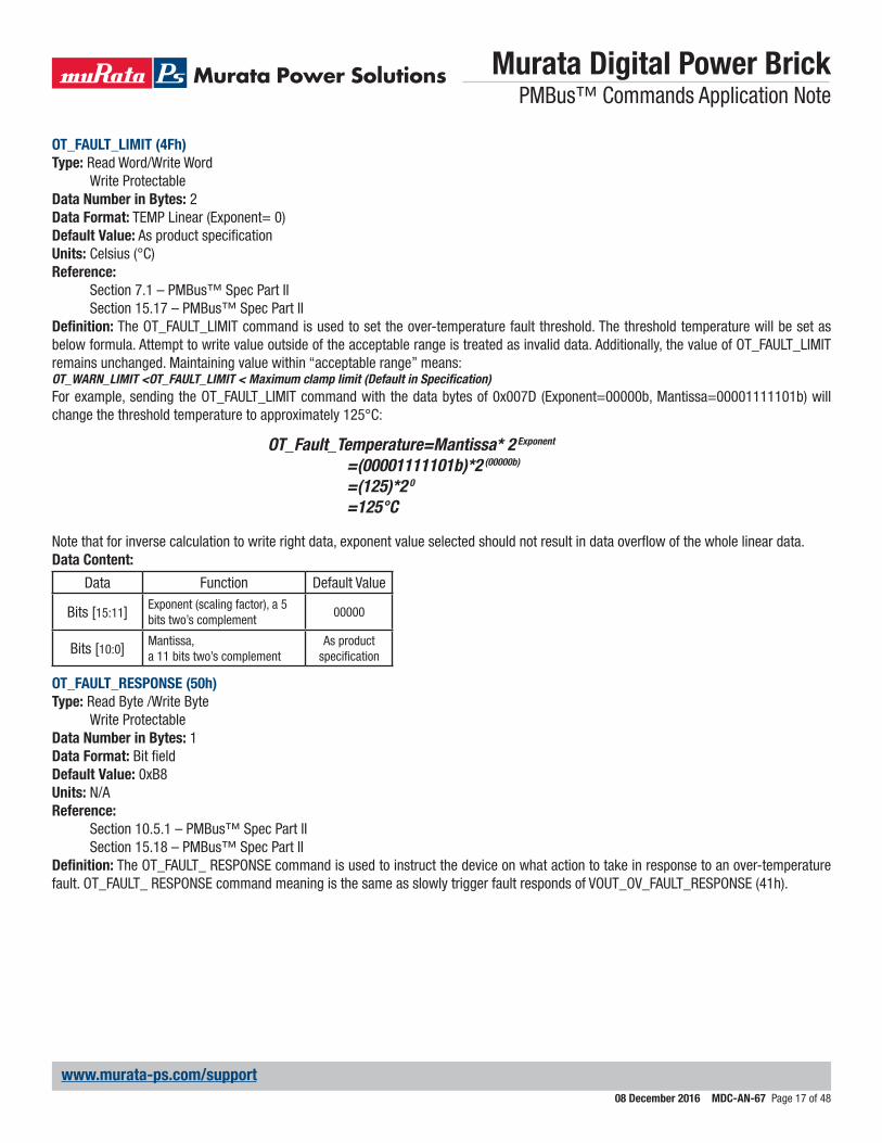
OT_FAULT_LIMIT (4Fh)Type: Read Word/Write Word
Write ProtectableData Number in Bytes: 2Data Format: TEMP Linear (Exponent= 0)Default Value: As product specificationUnits: Celsius (°C)Reference:
Section 7.1 – PMBus™ Spec Part IISection 15.17 – PMBus™ Spec Part II
Definition: The OT_FAULT_LIMIT command is used to set the over-temperature fault threshold. The threshold temperature will be set as below formula. Attempt to write value outside of the acceptable range is treated as invalid data. Additionally, the value of OT_FAULT_LIMIT remains unchanged. Maintaining value within “acceptable range” means:OT_WARN_LIMIT <OT_FAULT_LIMIT < Maximum clamp limit (Default in Specification)For example, sending the OT_FAULT_LIMIT command with the data bytes of 0x007D (Exponent=00000b, Mantissa=00001111101b) will change the threshold temperature to approximately 125°C:
OT_Fault_Temperature=Mantissa* 2 Exponent
=(00001111101b)*2 (00000b)
=(125)*2 0 =125°C
Note that for inverse calculation to write right data, exponent value selected should not result in data overflow of the whole linear data.Data Content:
Data Function Default Value
Bits [15:11] Exponent (scaling factor), a 5 bits two’s complement
00000
Bits [10:0] Mantissa,a 11 bits two’s complement
As product specification
OT_FAULT_RESPONSE (50h)Type: Read Byte /Write Byte
Write ProtectableData Number in Bytes: 1Data Format: Bit fieldDefault Value: 0xB8Units: N/AReference:
Section 10.5.1 – PMBus™ Spec Part IISection 15.18 – PMBus™ Spec Part II
Definition: The OT_FAULT_ RESPONSE command is used to instruct the device on what action to take in response to an over-temperature fault. OT_FAULT_ RESPONSE command meaning is the same as slowly trigger fault responds of VOUT_OV_FAULT_RESPONSE (41h).
Murata Digital Power Brick PMBus™ Commands Application Note
08 December 2016 MDC-AN-67 Page 18 of 48
www.murata-ps.com/support
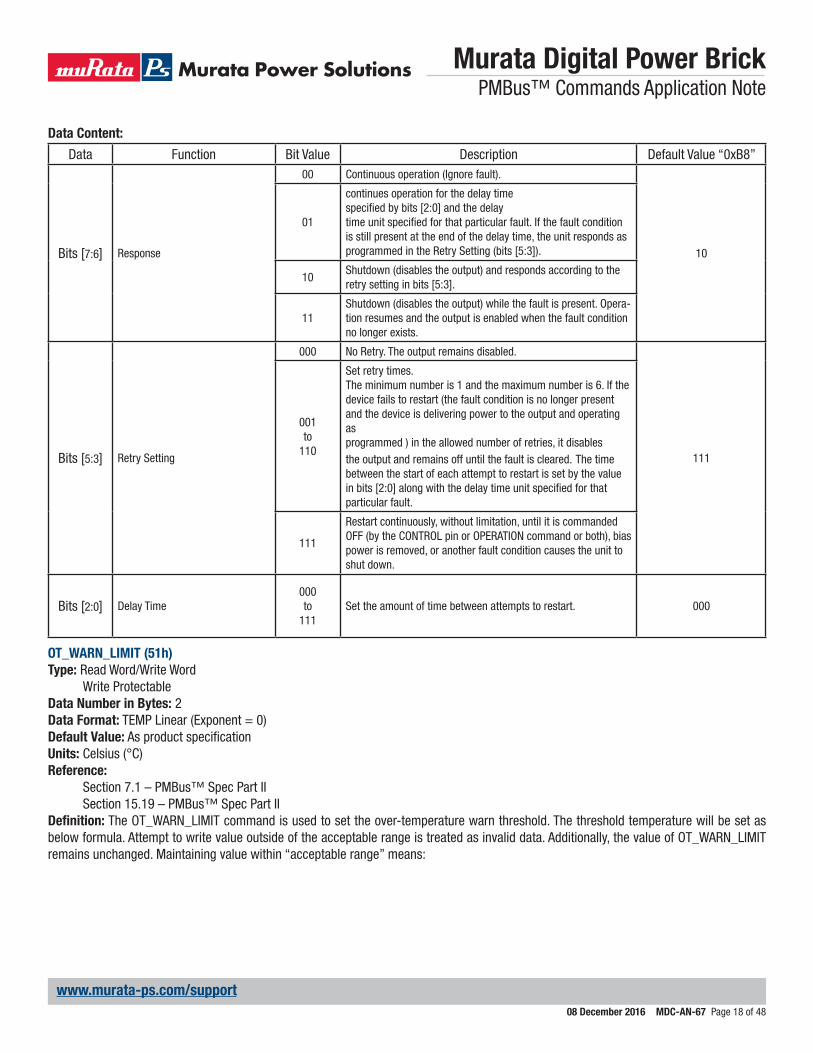
Data Content:
Data Function Bit Value Description Default Value “0xB8”
Bits [7:6] Response
00 Continuous operation (Ignore fault).
10
01
continues operation for the delay timespecified by bits [2:0] and the delaytime unit specified for that particular fault. If the fault condition is still present at the end of the delay time, the unit responds as programmed in the Retry Setting (bits [5:3]).
10Shutdown (disables the output) and responds according to the retry setting in bits [5:3].
11Shutdown (disables the output) while the fault is present. Opera-tion resumes and the output is enabled when the fault condition no longer exists.
Bits [5:3] Retry Setting
000 No Retry. The output remains disabled.
111
001to
110
Set retry times.The minimum number is 1 and the maximum number is 6. If the device fails to restart (the fault condition is no longer present and the device is delivering power to the output and operating asprogrammed ) in the allowed number of retries, it disables the output and remains off until the fault is cleared. The time between the start of each attempt to restart is set by the value in bits [2:0] along with the delay time unit specified for that particular fault.
111
Restart continuously, without limitation, until it is commanded OFF (by the CONTROL pin or OPERATION command or both), bias power is removed, or another fault condition causes the unit to shut down.
Bits [2:0] Delay Time000to
111Set the amount of time between attempts to restart. 000
OT_WARN_LIMIT (51h)Type: Read Word/Write Word
Write ProtectableData Number in Bytes: 2Data Format: TEMP Linear (Exponent = 0)Default Value: As product specificationUnits: Celsius (°C)Reference:
Section 7.1 – PMBus™ Spec Part IISection 15.19 – PMBus™ Spec Part II
Definition: The OT_WARN_LIMIT command is used to set the over-temperature warn threshold. The threshold temperature will be set as below formula. Attempt to write value outside of the acceptable range is treated as invalid data. Additionally, the value of OT_WARN_LIMIT remains unchanged. Maintaining value within “acceptable range” means:

Murata Digital Power Brick PMBus™ Commands Application Note
08 December 2016 MDC-AN-67 Page 19 of 48
www.murata-ps.com/support
OT_WARN_LIMIT <OT_FAULT_LIMITFor example, sending the OT_WARN_LIMIT command with the data bytes of 0x0078 (Exponent=00000b, Mantissa=00001111000b) will change the threshold temperature to approximately 120°C:
OT_Warn_Temperature=Mantissa* 2 Exponent
=(00001111000b)*2 (00000b)
=(120)*2 0 =120°C
Note that for inverse calculation to write right data, exponent value selected should not result in data overflow of the whole linear data.Data Content:
Data Function Default Value
Bits [15:11] Exponent (scaling factor), a 5 bits two’s complement
00000
Bits [10:0] Mantissa,a 11 bits two’s complement
As product specification
VIN_OV_FAULT_LIMIT (55h)Type: Read Word/Write Word
Write ProtectableData Number in Bytes: 2Data Format: Vin Linear
(Exponent is not fixed, range from -16 to 15)Default Value: As product specificationUnits: Volts (V)Reference:
Section 7.1 – PMBus™ Spec Part IISection 15.23 – PMBus™ Spec Part II
Definition: The VIN_OV_FAULT_LIMIT command is used to set the input overvoltage fault threshold. The threshold voltage will be set as be-low formula. Attempt to write value outside of the acceptable range is treated as invalid data. Additionally, the value of VIN_OV_FAULT_LIMIT remains unchanged. Maintaining value within “acceptable range” means:VIN_OV_WARN_LIMIT < VIN_OV_FAULT_LIMIT < Maximum clamp limit (Default in Specification)For example, sending the VIN_OV_FAULT_LIMIT command with the data bytes of 0xEA80 (Exponent=11101b, Mantissa=01010000000b) will change the threshold voltage to approximately 80.0V:
OV_Fault_Voltage=Mantissa* 2 Exponent
=(01010000000b)*2 (11101b)
=(640)*2 -3
=80.0 V
Note that for inverse calculation to write right data, exponent value selected should not result in data overflow of the whole linear data.Data Content:
Data Function Default Value
Bits [15:11] Exponent (scaling factor), a 5 bits two’s complement As product
specificationBits [10:0] Mantissa,
a 11 bits two’s complement
Murata Digital Power Brick PMBus™ Commands Application Note
08 December 2016 MDC-AN-67 Page 20 of 48
www.murata-ps.com/support
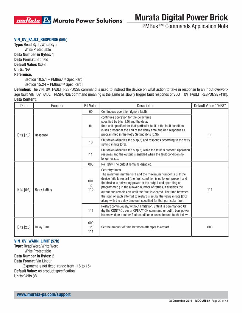
VIN_OV_FAULT_RESPONSE (56h)Type: Read Byte /Write Byte
Write ProtectableData Number in Bytes: 1Data Format: Bit fieldDefault Value: 0xF8Units: N/AReference:
Section 10.5.1 – PMBus™ Spec Part IISection 15.24 – PMBus™ Spec Part II
Definition: The VIN_OV_FAULT_RESPONSE command is used to instruct the device on what action to take in response to an input overvolt-age fault. VIN_OV_FAULT_RESPONSE command meaning is the same as slowly trigger fault responds of VOUT_OV_FAULT_RESPONSE (41h).Data Content:
Data Function Bit Value Description Default Value “0xF8”
Bits [7:6] Response
00 Continuous operation (Ignore fault).
11
01
continues operation for the delay timespecified by bits [2:0] and the delaytime unit specified for that particular fault. If the fault condition is still present at the end of the delay time, the unit responds as programmed in the Retry Setting (bits [5:3]).
10Shutdown (disables the output) and responds according to the retry setting in bits [5:3].
11Shutdown (disables the output) while the fault is present. Operation resumes and the output is enabled when the fault condition no longer exists.
Bits [5:3] Retry Setting
000 No Retry. The output remains disabled.
111
001to
110
Set retry times.The minimum number is 1 and the maximum number is 6. If the device fails to restart (the fault condition is no longer present and the device is delivering power to the output and operating asprogrammed ) in the allowed number of retries, it disables the output and remains off until the fault is cleared. The time between the start of each attempt to restart is set by the value in bits [2:0] along with the delay time unit specified for that particular fault.
111Restart continuously, without limitation, until it is commanded OFF (by the CONTROL pin or OPERATION command or both), bias power is removed, or another fault condition causes the unit to shut down.
Bits [2:0] Delay Time000to
111Set the amount of time between attempts to restart. 000
VIN_OV_WARN_LIMIT (57h)Type: Read Word/Write Word
Write ProtectableData Number in Bytes: 2Data Format: Vin Linear
(Exponent is not fixed, range from -16 to 15)Default Value: As product specificationUnits: Volts (V)
Murata Digital Power Brick PMBus™ Commands Application Note
08 December 2016 MDC-AN-67 Page 21 of 48
www.murata-ps.com/support
Reference:Section 7.1 – PMBus™ Spec Part IISection 15.25 – PMBus™ Spec Part II
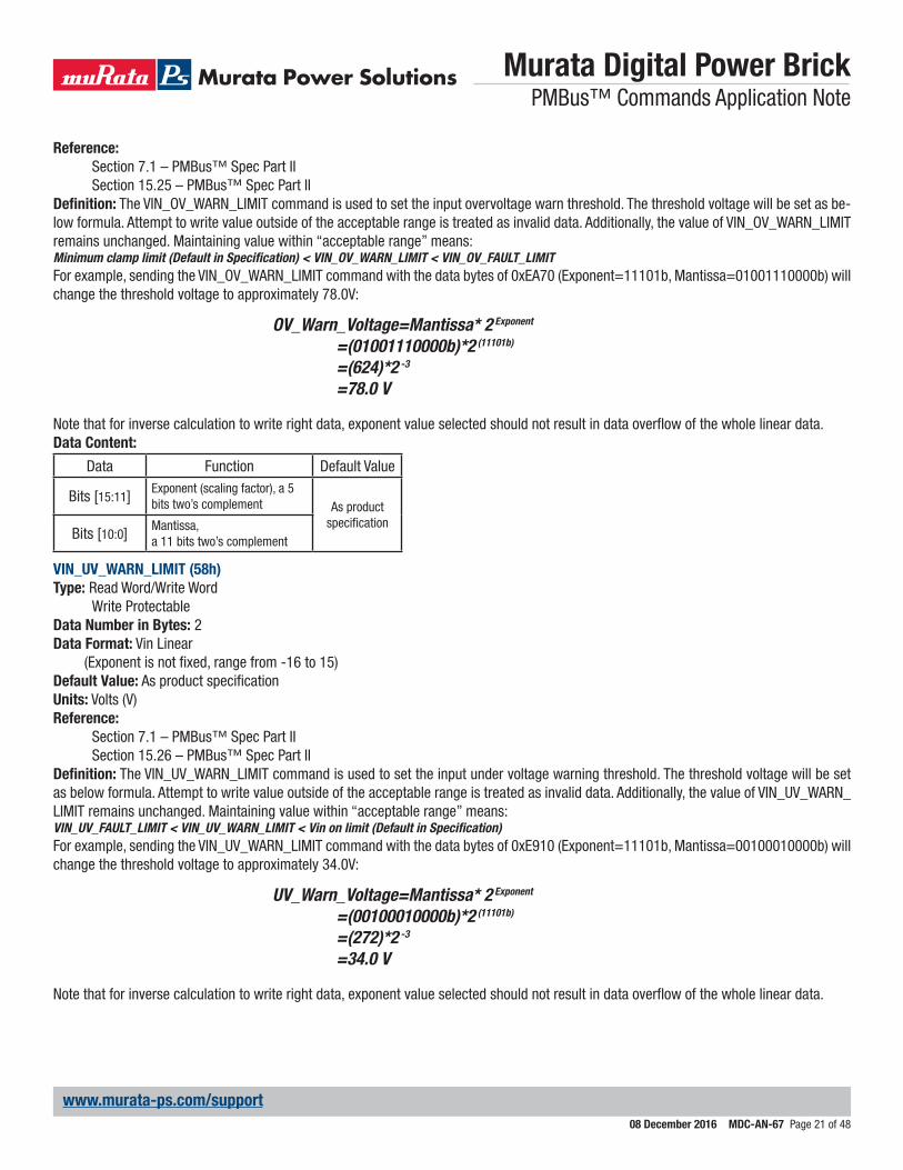
Definition: The VIN_OV_WARN_LIMIT command is used to set the input overvoltage warn threshold. The threshold voltage will be set as be-low formula. Attempt to write value outside of the acceptable range is treated as invalid data. Additionally, the value of VIN_OV_WARN_LIMIT remains unchanged. Maintaining value within “acceptable range” means:Minimum clamp limit (Default in Specification) < VIN_OV_WARN_LIMIT < VIN_OV_FAULT_LIMITFor example, sending the VIN_OV_WARN_LIMIT command with the data bytes of 0xEA70 (Exponent=11101b, Mantissa=01001110000b) will change the threshold voltage to approximately 78.0V:
OV_Warn_Voltage=Mantissa* 2 Exponent
=(01001110000b)*2 (11101b)
=(624)*2 -3
=78.0 V
Note that for inverse calculation to write right data, exponent value selected should not result in data overflow of the whole linear data.Data Content:
Data Function Default Value
Bits [15:11] Exponent (scaling factor), a 5 bits two’s complement As product
specificationBits [10:0] Mantissa,
a 11 bits two’s complement
VIN_UV_WARN_LIMIT (58h)Type: Read Word/Write Word
Write ProtectableData Number in Bytes: 2Data Format: Vin Linear
(Exponent is not fixed, range from -16 to 15)Default Value: As product specificationUnits: Volts (V)Reference:
Section 7.1 – PMBus™ Spec Part IISection 15.26 – PMBus™ Spec Part II
Definition: The VIN_UV_WARN_LIMIT command is used to set the input under voltage warning threshold. The threshold voltage will be set as below formula. Attempt to write value outside of the acceptable range is treated as invalid data. Additionally, the value of VIN_UV_WARN_LIMIT remains unchanged. Maintaining value within “acceptable range” means:VIN_UV_FAULT_LIMIT < VIN_UV_WARN_LIMIT < Vin on limit (Default in Specification)For example, sending the VIN_UV_WARN_LIMIT command with the data bytes of 0xE910 (Exponent=11101b, Mantissa=00100010000b) will change the threshold voltage to approximately 34.0V:
UV_Warn_Voltage=Mantissa* 2 Exponent
=(00100010000b)*2 (11101b)
=(272)*2 -3
=34.0 V
Note that for inverse calculation to write right data, exponent value selected should not result in data overflow of the whole linear data.
Murata Digital Power Brick PMBus™ Commands Application Note
08 December 2016 MDC-AN-67 Page 22 of 48
www.murata-ps.com/support
Data Content:
Data Function Default Value
Bits [15:11] Exponent (scaling factor), a 5 bits two’s complement As product
specificationBits [10:0] Mantissa,
a 11 bits two’s complement
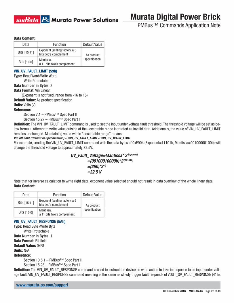
VIN_UV_FAULT_LIMIT (59h)Type: Read Word/Write Word
Write ProtectableData Number in Bytes: 2Data Format: Vin Linear
(Exponent is not fixed, range from -16 to 15)Default Value: As product specificationUnits: Volts (V)Reference:
Section 7.1 – PMBus™ Spec Part IISection 15.27 – PMBus™ Spec Part II
Definition: The VIN_UV_FAULT_LIMIT command is used to set the input under voltage fault threshold. The threshold voltage will be set as be-low formula. Attempt to write value outside of the acceptable range is treated as invalid data. Additionally, the value of VIN_UV_FAULT_LIMIT remains unchanged. Maintaining value within “acceptable range” means:Vin off limit (Default in Specification) < VIN_UV_FAULT_LIMIT < VIN_UV_WARN_LIMITFor example, sending the VIN_UV_FAULT_LIMIT command with the data bytes of 0xE904 (Exponent=11101b, Mantissa=00100000100b) will change the threshold voltage to approximately 32.5V:
UV_Fault_Voltage=Mantissa* 2 Exponent
=(00100010000b)*2 (11101b)
=(260)*2 -3
=32.5 V
Note that for inverse calculation to write right data, exponent value selected should not result in data overflow of the whole linear data.Data Content:
Data Function Default Value
Bits [15:11] Exponent (scaling factor), a 5 bits two’s complement As product
specificationBits [10:0] Mantissa,
a 11 bits two’s complement
VIN_UV_FAULT_RESPONSE (5Ah)Type: Read Byte /Write Byte
Write ProtectableData Number in Bytes: 1Data Format: Bit fieldDefault Value: 0xF8Units: N/AReference:
Section 10.5.1 – PMBus™ Spec Part IISection 15.28 – PMBus™ Spec Part II
Definition: The VIN_UV_FAULT_RESPONSE command is used to instruct the device on what action to take in response to an input under volt-age fault. VIN_UV_FAULT_RESPONSE command meaning is the same as slowly trigger fault responds of VOUT_OV_FAULT_RESPONSE (41h).
Murata Digital Power Brick PMBus™ Commands Application Note
08 December 2016 MDC-AN-67 Page 23 of 48
www.murata-ps.com/support
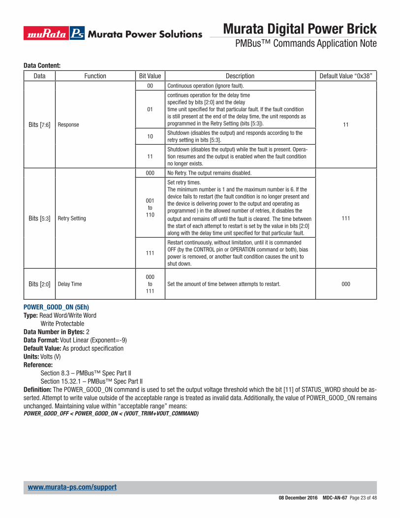
Data Content:
Data Function Bit Value Description Default Value “0x38”
Bits [7:6] Response
00 Continuous operation (Ignore fault).
11
01
continues operation for the delay timespecified by bits [2:0] and the delaytime unit specified for that particular fault. If the fault condition is still present at the end of the delay time, the unit responds as programmed in the Retry Setting (bits [5:3]).
10Shutdown (disables the output) and responds according to the retry setting in bits [5:3].
11Shutdown (disables the output) while the fault is present. Opera-tion resumes and the output is enabled when the fault condition no longer exists.
Bits [5:3] Retry Setting
000 No Retry. The output remains disabled.
111
001to
110
Set retry times.The minimum number is 1 and the maximum number is 6. If the device fails to restart (the fault condition is no longer present and the device is delivering power to the output and operating asprogrammed ) in the allowed number of retries, it disables the output and remains off until the fault is cleared. The time between the start of each attempt to restart is set by the value in bits [2:0] along with the delay time unit specified for that particular fault.
111
Restart continuously, without limitation, until it is commanded OFF (by the CONTROL pin or OPERATION command or both), bias power is removed, or another fault condition causes the unit to shut down.
Bits [2:0] Delay Time000to
111Set the amount of time between attempts to restart. 000
POWER_GOOD_ON (5Eh)Type: Read Word/Write Word
Write ProtectableData Number in Bytes: 2Data Format: Vout Linear (Exponent=-9)Default Value: As product specificationUnits: Volts (V)Reference:
Section 8.3 – PMBus™ Spec Part IISection 15.32.1 – PMBus™ Spec Part II
Definition: The POWER_GOOD_ON command is used to set the output voltage threshold which the bit [11] of STATUS_WORD should be as-serted. Attempt to write value outside of the acceptable range is treated as invalid data. Additionally, the value of POWER_GOOD_ON remains unchanged. Maintaining value within “acceptable range” means:POWER_GOOD_OFF < POWER_GOOD_ON < (VOUT_TRIM+VOUT_COMMAND)
Murata Digital Power Brick PMBus™ Commands Application Note
08 December 2016 MDC-AN-67 Page 24 of 48
www.murata-ps.com/support
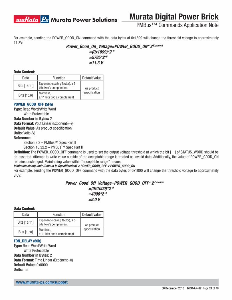
For example, sending the POWER_GOOD_ON command with the data bytes of 0x1699 will change the threshold voltage to approximately 11.3V:
Power_Good_On_Voltage=POWER_GOOD_ON* 2 Exponent
=(0x1699)*2 -9
=5785*2 -9
=11.3 V
Data Content:
Data Function Default Value
Bits [15:11] Exponent (scaling factor), a 5 bits two’s complement As product
specificationBits [10:0] Mantissa,
a 11 bits two’s complement
POWER_GOOD_OFF (5Fh)Type: Read Word/Write Word
Write ProtectableData Number in Bytes: 2Data Format: Vout Linear (Exponent=-9)Default Value: As product specificationUnits: Volts (V)Reference:
Section 8.3 – PMBus™ Spec Part IISection 15.32.2 – PMBus™ Spec Part II
Definition: The POWER_GOOD_OFF command is used to set the output voltage threshold at which the bit [11] of STATUS_WORD should be de-asserted. Attempt to write value outside of the acceptable range is treated as invalid data. Additionally, the value of POWER_GOOD_ON remains unchanged. Maintaining value within “acceptable range” means:Minimum clamp limit (Default in Specification) < POWER_GOOD_OFF < POWER_GOOD_ONFor example, sending the POWER_GOOD_OFF command with the data bytes of 0x1000 will change the threshold voltage to approximately 8.0V:
Power_Good_Off_Voltage=POWER_GOOD_OFF* 2 Exponent
=(0x1000)*2 -9
=4096*2 -9
=8.0 V
Data Content:
Data Function Default Value
Bits [15:11] Exponent (scaling factor), a 5 bits two’s complement As product
specificationBits [10:0] Mantissa,
a 11 bits two’s complement
TON_DELAY (60h)Type: Read Word/Write Word
Write ProtectableData Number in Bytes: 2Data Format: Time Linear (Exponent=0)Default Value: 0x0000Units: ms
Murata Digital Power Brick PMBus™ Commands Application Note
08 December 2016 MDC-AN-67 Page 25 of 48
www.murata-ps.com/support
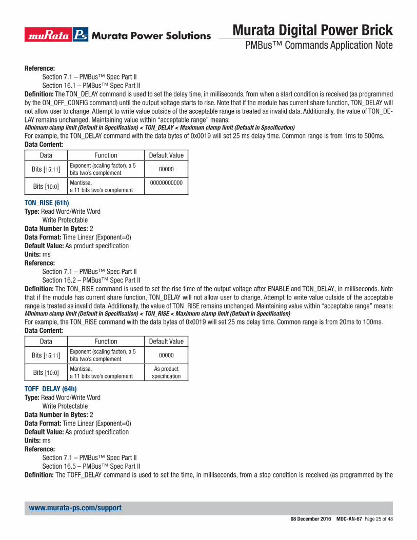
Reference:Section 7.1 – PMBus™ Spec Part IISection 16.1 – PMBus™ Spec Part II
Definition: The TON_DELAY command is used to set the delay time, in milliseconds, from when a start condition is received (as programmed by the ON_OFF_CONFIG command) until the output voltage starts to rise. Note that if the module has current share function, TON_DELAY will not allow user to change. Attempt to write value outside of the acceptable range is treated as invalid data. Additionally, the value of TON_DE-LAY remains unchanged. Maintaining value within “acceptable range” means:Minimum clamp limit (Default in Specification) < TON_DELAY < Maximum clamp limit (Default in Specification)For example, the TON_DELAY command with the data bytes of 0x0019 will set 25 ms delay time. Common range is from 1ms to 500ms.Data Content:
Data Function Default Value
Bits [15:11] Exponent (scaling factor), a 5 bits two’s complement
00000
Bits [10:0] Mantissa,a 11 bits two’s complement
00000000000
TON_RISE (61h)Type: Read Word/Write Word
Write ProtectableData Number in Bytes: 2Data Format: Time Linear (Exponent=0)Default Value: As product specificationUnits: msReference:
Section 7.1 – PMBus™ Spec Part IISection 16.2 – PMBus™ Spec Part II
Definition: The TON_RISE command is used to set the rise time of the output voltage after ENABLE and TON_DELAY, in milliseconds. Note that if the module has current share function, TON_DELAY will not allow user to change. Attempt to write value outside of the acceptable range is treated as invalid data. Additionally, the value of TON_RISE remains unchanged. Maintaining value within “acceptable range” means:Minimum clamp limit (Default in Specification) < TON_RISE < Maximum clamp limit (Default in Specification)For example, the TON_RISE command with the data bytes of 0x0019 will set 25 ms delay time. Common range is from 20ms to 100ms.Data Content:
Data Function Default Value
Bits [15:11] Exponent (scaling factor), a 5 bits two’s complement
00000
Bits [10:0] Mantissa,a 11 bits two’s complement
As product specification
TOFF_DELAY (64h)Type: Read Word/Write Word
Write ProtectableData Number in Bytes: 2Data Format: Time Linear (Exponent=0)Default Value: As product specificationUnits: msReference:
Section 7.1 – PMBus™ Spec Part IISection 16.5 – PMBus™ Spec Part II
Definition: The TOFF_DELAY command is used to set the time, in milliseconds, from a stop condition is received (as programmed by the
Murata Digital Power Brick PMBus™ Commands Application Note
08 December 2016 MDC-AN-67 Page 26 of 48
www.murata-ps.com/support
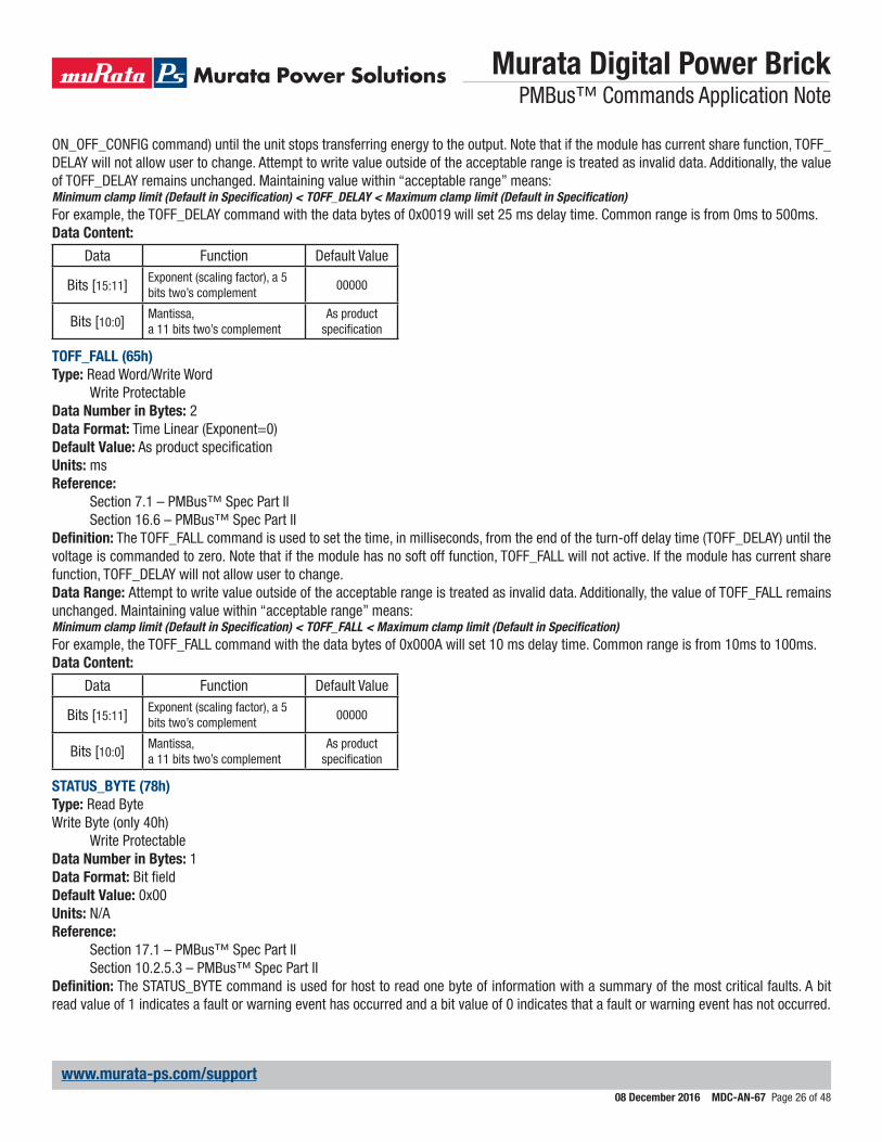
ON_OFF_CONFIG command) until the unit stops transferring energy to the output. Note that if the module has current share function, TOFF_DELAY will not allow user to change. Attempt to write value outside of the acceptable range is treated as invalid data. Additionally, the value of TOFF_DELAY remains unchanged. Maintaining value within “acceptable range” means:Minimum clamp limit (Default in Specification) < TOFF_DELAY < Maximum clamp limit (Default in Specification)For example, the TOFF_DELAY command with the data bytes of 0x0019 will set 25 ms delay time. Common range is from 0ms to 500ms.Data Content:
Data Function Default Value
Bits [15:11] Exponent (scaling factor), a 5 bits two’s complement
00000
Bits [10:0] Mantissa,a 11 bits two’s complement
As product specification
TOFF_FALL (65h)Type: Read Word/Write Word
Write ProtectableData Number in Bytes: 2Data Format: Time Linear (Exponent=0)Default Value: As product specificationUnits: msReference:
Section 7.1 – PMBus™ Spec Part IISection 16.6 – PMBus™ Spec Part II
Definition: The TOFF_FALL command is used to set the time, in milliseconds, from the end of the turn-off delay time (TOFF_DELAY) until the voltage is commanded to zero. Note that if the module has no soft off function, TOFF_FALL will not active. If the module has current share function, TOFF_DELAY will not allow user to change.Data Range: Attempt to write value outside of the acceptable range is treated as invalid data. Additionally, the value of TOFF_FALL remains unchanged. Maintaining value within “acceptable range” means:Minimum clamp limit (Default in Specification) < TOFF_FALL < Maximum clamp limit (Default in Specification)For example, the TOFF_FALL command with the data bytes of 0x000A will set 10 ms delay time. Common range is from 10ms to 100ms.Data Content:
Data Function Default Value
Bits [15:11] Exponent (scaling factor), a 5 bits two’s complement
00000
Bits [10:0] Mantissa,a 11 bits two’s complement
As product specification
STATUS_BYTE (78h)Type: Read ByteWrite Byte (only 40h)
Write ProtectableData Number in Bytes: 1Data Format: Bit fieldDefault Value: 0x00Units: N/AReference:
Section 17.1 – PMBus™ Spec Part IISection 10.2.5.3 – PMBus™ Spec Part II
Definition: The STATUS_BYTE command is used for host to read one byte of information with a summary of the most critical faults. A bit read value of 1 indicates a fault or warning event has occurred and a bit value of 0 indicates that a fault or warning event has not occurred.
Murata Digital Power Brick PMBus™ Commands Application Note
08 December 2016 MDC-AN-67 Page 27 of 48
www.murata-ps.com/support
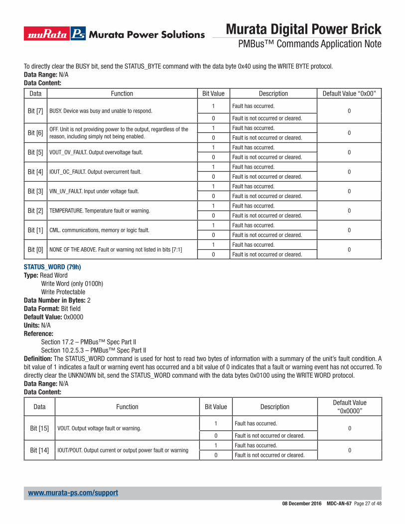
To directly clear the BUSY bit, send the STATUS_BYTE command with the data byte 0x40 using the WRITE BYTE protocol.Data Range: N/AData Content:
Data Function Bit Value Description Default Value “0x00”
Bit [7] BUSY. Device was busy and unable to respond.1 Fault has occurred.
00 Fault is not occurred or cleared.
Bit [6] OFF. Unit is not providing power to the output, regardless of the reason, including simply not being enabled.
1 Fault has occurred.0
0 Fault is not occurred or cleared.
Bit [5] VOUT_OV_FAULT. Output overvoltage fault.1 Fault has occurred.
00 Fault is not occurred or cleared.
Bit [4] IOUT_OC_FAULT. Output overcurrent fault.1 Fault has occurred.
00 Fault is not occurred or cleared.
Bit [3] VIN_UV_FAULT. Input under voltage fault.1 Fault has occurred.
00 Fault is not occurred or cleared.
Bit [2] TEMPERATURE. Temperature fault or warning.1 Fault has occurred.
00 Fault is not occurred or cleared.
Bit [1] CML. communications, memory or logic fault.1 Fault has occurred.
00 Fault is not occurred or cleared.
Bit [0] NONE OF THE ABOVE. Fault or warning not listed in bits [7:1]1 Fault has occurred.
00 Fault is not occurred or cleared.
STATUS_WORD (79h)Type: Read Word
Write Word (only 0100h)Write Protectable
Data Number in Bytes: 2Data Format: Bit fieldDefault Value: 0x0000Units: N/AReference:
Section 17.2 – PMBus™ Spec Part IISection 10.2.5.3 – PMBus™ Spec Part II
Definition: The STATUS_WORD command is used for host to read two bytes of information with a summary of the unit’s fault condition. A bit value of 1 indicates a fault or warning event has occurred and a bit value of 0 indicates that a fault or warning event has not occurred. To directly clear the UNKNOWN bit, send the STATUS_WORD command with the data bytes 0x0100 using the WRITE WORD protocol.Data Range: N/AData Content:
Data Function Bit Value DescriptionDefault Value
“0x0000”
Bit [15] VOUT. Output voltage fault or warning.1 Fault has occurred.
00 Fault is not occurred or cleared.
Bit [14] IOUT/POUT. Output current or output power fault or warning1 Fault has occurred.
00 Fault is not occurred or cleared.
Murata Digital Power Brick PMBus™ Commands Application Note
08 December 2016 MDC-AN-67 Page 28 of 48
www.murata-ps.com/support
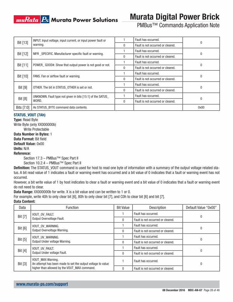
Bit [13] INPUT. Input voltage, input current, or input power fault or warning.
1 Fault has occurred.0
0 Fault is not occurred or cleared.
Bit [12] MFR _SPECIFIC. Manufacturer specific fault or warning.1 Fault has occurred.
00 Fault is not occurred or cleared.
Bit [11] POWER_ GOOD#. Show that output power is not good or not.1 Fault has occurred.
00 Fault is not occurred or cleared.
Bit [10] FANS. Fan or airflow fault or warning.1 Fault has occurred.
00 Fault is not occurred or cleared.
Bit [9] OTHER. The bit in STATUS_OTHER is set or not.1 Fault has occurred.
00 Fault is not occurred or cleared.
Bit [8] UNKNOWN. Fault type not given in bits [15:1] of the SATUS_WORD.
1 Fault has occurred.0
0 Fault is not occurred or cleared.
Bits [7:0] As STATUS_BYTE command data contents. 0x00
STATUS_VOUT (7Ah)Type: Read ByteWrite Byte (only XX000000b)
Write ProtectableData Number in Bytes: 1Data Format: Bit fieldDefault Value: 0x00Units: N/AReference:
Section 17.3 – PMBus™ Spec Part IISection 10.2.4 – PMBus™ Spec Part II
Definition: The STATUS_VOUT command is used for host to read one byte of information with a summary of the output voltage related sta-tus. A bit read value of 1 indicates a fault or warning event has occurred and a bit value of 0 indicates that a fault or warning event has not occurred.However, a bit write value of 1 by host indicates to clear a fault or warning event and a bit value of 0 indicates that a fault or warning event do not need to clear.Data Range: XX000000b for write. X is a bit value and can be written to 1 or 0.For example, write 40h to only clear bit [6], 80h to only clear bit [7], and C0h to clear bit [6] and bit [7].Data Content:
Data Function Bit Value Description Default Value “0x00”
Bit [7] VOUT_OV_FAULT.Output Overvoltage Fault.
1 Fault has occurred.0
0 Fault is not occurred or cleared.
Bit [6] VOUT_OV_WARNING.Output Overvoltage Warning.
1 Fault has occurred.0
0 Fault is not occurred or cleared.
Bit [5] VOUT_UV_WARNING.Output Under voltage Warning.
1 Fault has occurred.0
0 Fault is not occurred or cleared.
Bit [4] VOUT_UV_FAULT.Output Under voltage Fault.
1 Fault has occurred.0
0 Fault is not occurred or cleared.
Bit [3]VOUT_MAX Warning.An attempt has been made to set the output voltage to value higher than allowed by the VOUT_MAX command.
1 Fault has occurred.0
0 Fault is not occurred or cleared.
Murata Digital Power Brick PMBus™ Commands Application Note
08 December 2016 MDC-AN-67 Page 29 of 48
www.murata-ps.com/support
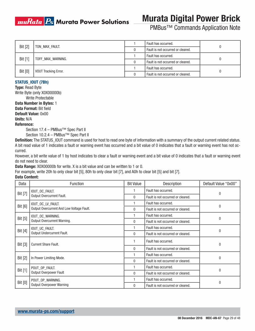
Bit [2] TON_MAX_FAULT.1 Fault has occurred.
00 Fault is not occurred or cleared.
Bit [1] TOFF_MAX_WARNING.1 Fault has occurred.
00 Fault is not occurred or cleared.
Bit [0] VOUT Tracking Error.1 Fault has occurred.
00 Fault is not occurred or cleared.
STATUS_IOUT (7Bh)Type: Read ByteWrite Byte (only X0X00000b)
Write ProtectableData Number in Bytes: 1Data Format: Bit fieldDefault Value: 0x00Units: N/AReference:
Section 17.4 – PMBus™ Spec Part IISection 10.2.4 – PMBus™ Spec Part II
Definition: The STATUS_IOUT command is used for host to read one byte of information with a summary of the output current related status. A bit read value of 1 indicates a fault or warning event has occurred and a bit value of 0 indicates that a fault or warning event has not oc-curred.However, a bit write value of 1 by host indicates to clear a fault or warning event and a bit value of 0 indicates that a fault or warning event do not need to clear.Data Range: X0X00000b for write. X is a bit value and can be written to 1 or 0.For example, write 20h to only clear bit [5], 80h to only clear bit [7], and A0h to clear bit [5] and bit [7].Data Content:
Data Function Bit Value Description Default Value “0x00”
Bit [7] IOUT_OC_FAULT.Output Overcurrent Fault.
1 Fault has occurred.0
0 Fault is not occurred or cleared.
Bit [6] IOUT_OC_LV_FAULT.Output Overcurrent And Low Voltage Fault.
1 Fault has occurred.0
0 Fault is not occurred or cleared.
Bit [5] IOUT_OC_WARNING.Output Overcurrent Warning.
1 Fault has occurred.0
0 Fault is not occurred or cleared.
Bit [4] IOUT_UC_FAULT.Output Undercurrent Fault.
1 Fault has occurred.0
0 Fault is not occurred or cleared.
Bit [3] Current Share Fault.1 Fault has occurred.
00 Fault is not occurred or cleared.
Bit [2] In Power Limiting Mode.1 Fault has occurred.
00 Fault is not occurred or cleared.
Bit [1] POUT_OP_FAULT.Output Overpower Fault
1 Fault has occurred.0
0 Fault is not occurred or cleared.
Bit [0] POUT_OP_WARNING.Output Overpower Warning
1 Fault has occurred.0
0 Fault is not occurred or cleared.
Murata Digital Power Brick PMBus™ Commands Application Note
08 December 2016 MDC-AN-67 Page 30 of 48
www.murata-ps.com/support
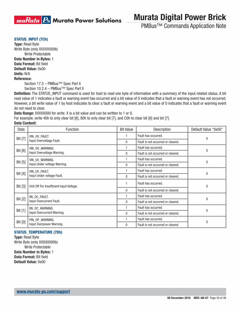
STATUS_INPUT (7Ch)Type: Read ByteWrite Byte (only XXXXX000b)
Write ProtectableData Number in Bytes: 1Data Format: Bit fieldDefault Value: 0x00Units: N/AReference:
Section 17.5 – PMBus™ Spec Part IISection 10.2.4 – PMBus™ Spec Part II
Definition: The STATUS_INPUT command is used for host to read one byte of information with a summary of the input related status. A bit read value of 1 indicates a fault or warning event has occurred and a bit value of 0 indicates that a fault or warning event has not occurred. However, a bit write value of 1 by host indicates to clear a fault or warning event and a bit value of 0 indicates that a fault or warning event do not need to clear.Data Range: XXXXX000 for write. X is a bit value and can be written to 1 or 0.For example, write 40h to only clear bit [6], 80h to only clear bit [7], and C0h to clear bit [6] and bit [7].Data Content:
Data Function Bit Value Description Default Value “0x00”
Bit [7] VIN_OV_FAULT.Input Overvoltage Fault.
1 Fault has occurred.0
0 Fault is not occurred or cleared.
Bit [6] VIN_OV_WARNING.Input Overvoltage Warning.
1 Fault has occurred.0
0 Fault is not occurred or cleared.
Bit [5] VIN_UV_WARNING.Input Under voltage Warning.
1 Fault has occurred.0
0 Fault is not occurred or cleared.
Bit [4] VIN_UV_FAULT.Input Under voltage Fault.
1 Fault has occurred.0
0 Fault is not occurred or cleared.
Bit [3] Unit Off For Insufficient Input Voltage.1 Fault has occurred.
00 Fault is not occurred or cleared.
Bit [2] IIN_OC_FAULT.Input Overcurrent Fault.
1 Fault has occurred.0
0 Fault is not occurred or cleared.
Bit [1] IIN_OC_WARNING.Input Overcurrent Warning.
1 Fault has occurred.0
0 Fault is not occurred or cleared.
Bit [0] PIN_OP_WARNING.Input Overpower Warning.
1 Fault has occurred.0
0 Fault is not occurred or cleared.
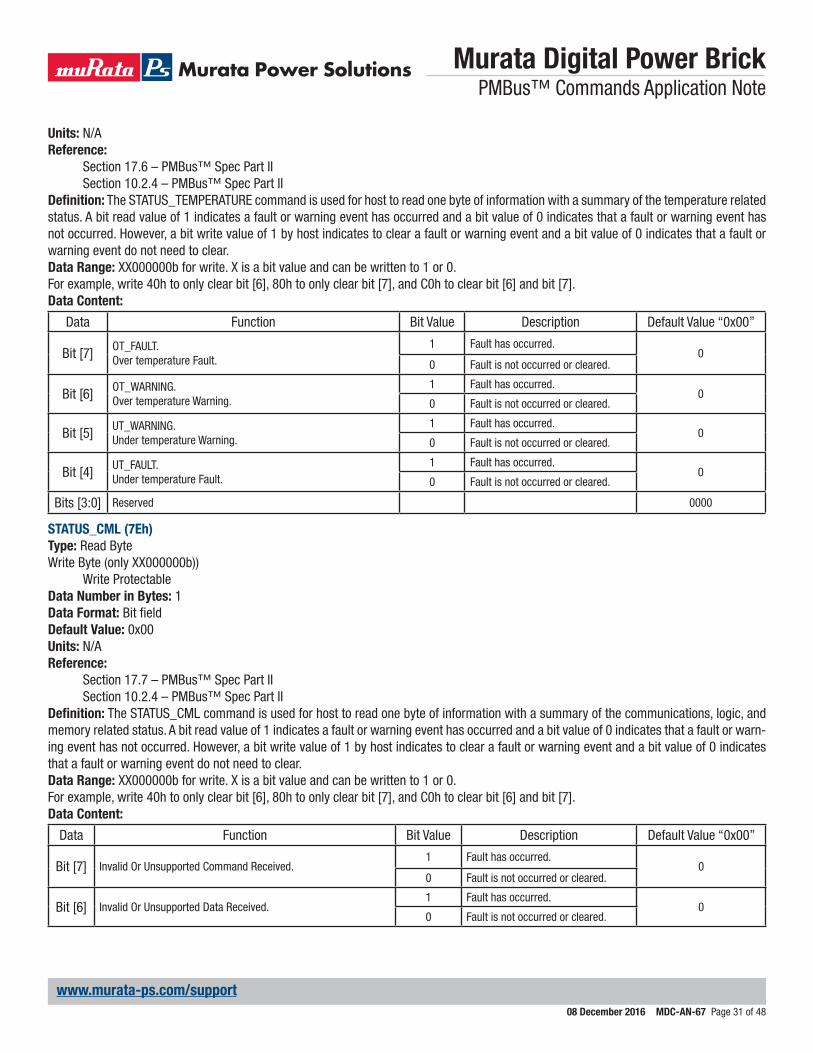
STATUS_TEMPERATURE (7Dh)Type: Read ByteWrite Byte (only XX000000b)
Write ProtectableData Number in Bytes: 1Data Format: Bit fieldDefault Value: 0x00
Murata Digital Power Brick PMBus™ Commands Application Note
08 December 2016 MDC-AN-67 Page 31 of 48
www.murata-ps.com/support
Units: N/AReference:
Section 17.6 – PMBus™ Spec Part IISection 10.2.4 – PMBus™ Spec Part II
Definition: The STATUS_TEMPERATURE command is used for host to read one byte of information with a summary of the temperature related status. A bit read value of 1 indicates a fault or warning event has occurred and a bit value of 0 indicates that a fault or warning event has not occurred. However, a bit write value of 1 by host indicates to clear a fault or warning event and a bit value of 0 indicates that a fault or warning event do not need to clear.Data Range: XX000000b for write. X is a bit value and can be written to 1 or 0.For example, write 40h to only clear bit [6], 80h to only clear bit [7], and C0h to clear bit [6] and bit [7].Data Content:
Data Function Bit Value Description Default Value “0x00”
Bit [7] OT_FAULT.Over temperature Fault.
1 Fault has occurred.0
0 Fault is not occurred or cleared.
Bit [6] OT_WARNING.Over temperature Warning.
1 Fault has occurred.0
0 Fault is not occurred or cleared.
Bit [5] UT_WARNING.Under temperature Warning.
1 Fault has occurred.0
0 Fault is not occurred or cleared.
Bit [4] UT_FAULT.Under temperature Fault.
1 Fault has occurred.0
0 Fault is not occurred or cleared.
Bits [3:0] Reserved 0000
STATUS_CML (7Eh)Type: Read ByteWrite Byte (only XX000000b))
Write ProtectableData Number in Bytes: 1Data Format: Bit fieldDefault Value: 0x00Units: N/AReference:
Section 17.7 – PMBus™ Spec Part IISection 10.2.4 – PMBus™ Spec Part II
Definition: The STATUS_CML command is used for host to read one byte of information with a summary of the communications, logic, and memory related status. A bit read value of 1 indicates a fault or warning event has occurred and a bit value of 0 indicates that a fault or warn-ing event has not occurred. However, a bit write value of 1 by host indicates to clear a fault or warning event and a bit value of 0 indicates that a fault or warning event do not need to clear.Data Range: XX000000b for write. X is a bit value and can be written to 1 or 0.For example, write 40h to only clear bit [6], 80h to only clear bit [7], and C0h to clear bit [6] and bit [7].Data Content:
Data Function Bit Value Description Default Value “0x00”
Bit [7] Invalid Or Unsupported Command Received.1 Fault has occurred.
00 Fault is not occurred or cleared.
Bit [6] Invalid Or Unsupported Data Received.1 Fault has occurred.
00 Fault is not occurred or cleared.
Murata Digital Power Brick PMBus™ Commands Application Note
08 December 2016 MDC-AN-67 Page 32 of 48
www.murata-ps.com/support
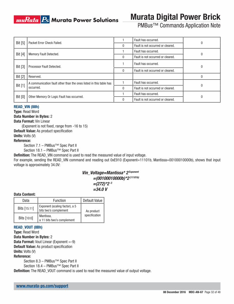
Bit [5] Packet Error Check Failed.1 Fault has occurred.
00 Fault is not occurred or cleared.
Bit [4] Memory Fault Detected.1 Fault has occurred.
00 Fault is not occurred or cleared.
Bit [3] Processor Fault Detected.1 Fault has occurred.
00 Fault is not occurred or cleared.
Bit [2] Reserved. 0
Bit [1] A communication fault other than the ones listed in this table has occurred.
1 Fault has occurred.0
0 Fault is not occurred or cleared.
Bit [0] Other Memory Or Logic Fault has occurred.1 Fault has occurred.
00 Fault is not occurred or cleared.
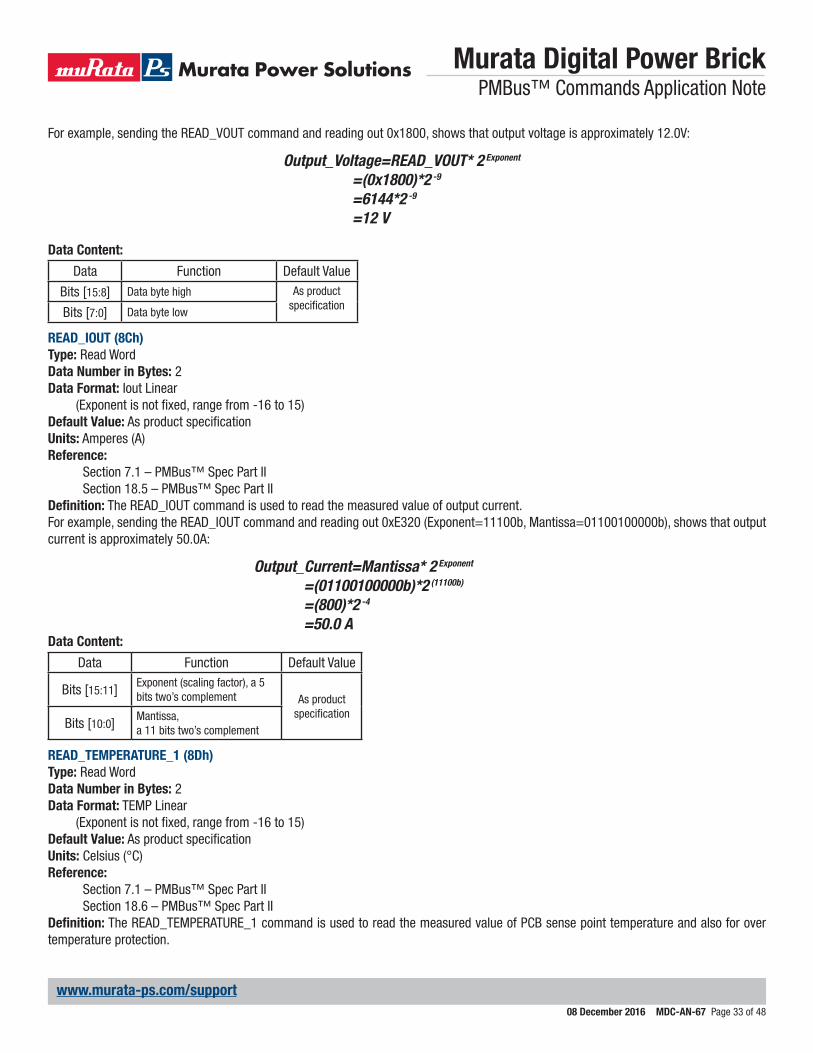
READ_VIN (88h)Type: Read WordData Number in Bytes: 2Data Format: Vin Linear
(Exponent is not fixed, range from -16 to 15)Default Value: As product specificationUnits: Volts (V)Reference:
Section 7.1 – PMBus™ Spec Part IISection 18.1 – PMBus™ Spec Part II
Definition: The READ_VIN command is used to read the measured value of input voltage.For example, sending the READ_VIN command and reading out 0xE910 (Exponent=11101b, Mantissa=00100010000b), shows that input voltage is approximately 34.0V:
Vin_Voltage=Mantissa* 2 Exponent
=(00100010000b)*2 (11101b)
=(272)*2 -3
=34.0 VData Content:
Data Function Default Value
Bits [15:11] Exponent (scaling factor), a 5 bits two’s complement As product
specificationBits [10:0] Mantissa,
a 11 bits two’s complement
READ_VOUT (8Bh)Type: Read WordData Number in Bytes: 2Data Format: Vout Linear (Exponent =-9)Default Value: As product specificationUnits: Volts (V)Reference:
Section 8.3 – PMBus™ Spec Part IISection 18.4 – PMBus™ Spec Part II
Definition: The READ_VOUT command is used to read the measured value of output voltage.
Murata Digital Power Brick PMBus™ Commands Application Note
08 December 2016 MDC-AN-67 Page 33 of 48
www.murata-ps.com/support
For example, sending the READ_VOUT command and reading out 0x1800, shows that output voltage is approximately 12.0V:
Output_Voltage=READ_VOUT* 2 Exponent
=(0x1800)*2 -9
=6144*2 -9
=12 V
Data Content:
Data Function Default Value
Bits [15:8] Data byte high As product specificationBits [7:0] Data byte low
READ_IOUT (8Ch)Type: Read WordData Number in Bytes: 2Data Format: Iout Linear
(Exponent is not fixed, range from -16 to 15)Default Value: As product specificationUnits: Amperes (A)Reference:
Section 7.1 – PMBus™ Spec Part IISection 18.5 – PMBus™ Spec Part II
Definition: The READ_IOUT command is used to read the measured value of output current.For example, sending the READ_IOUT command and reading out 0xE320 (Exponent=11100b, Mantissa=01100100000b), shows that output current is approximately 50.0A:
Output_Current=Mantissa* 2 Exponent
=(01100100000b)*2 (11100b)
=(800)*2 -4
=50.0 AData Content:
Data Function Default Value
Bits [15:11] Exponent (scaling factor), a 5 bits two’s complement As product
specificationBits [10:0] Mantissa,
a 11 bits two’s complement
READ_TEMPERATURE_1 (8Dh)Type: Read WordData Number in Bytes: 2Data Format: TEMP Linear
(Exponent is not fixed, range from -16 to 15)Default Value: As product specificationUnits: Celsius (°C)Reference:
Section 7.1 – PMBus™ Spec Part IISection 18.6 – PMBus™ Spec Part II
Definition: The READ_TEMPERATURE_1 command is used to read the measured value of PCB sense point temperature and also for over temperature protection.
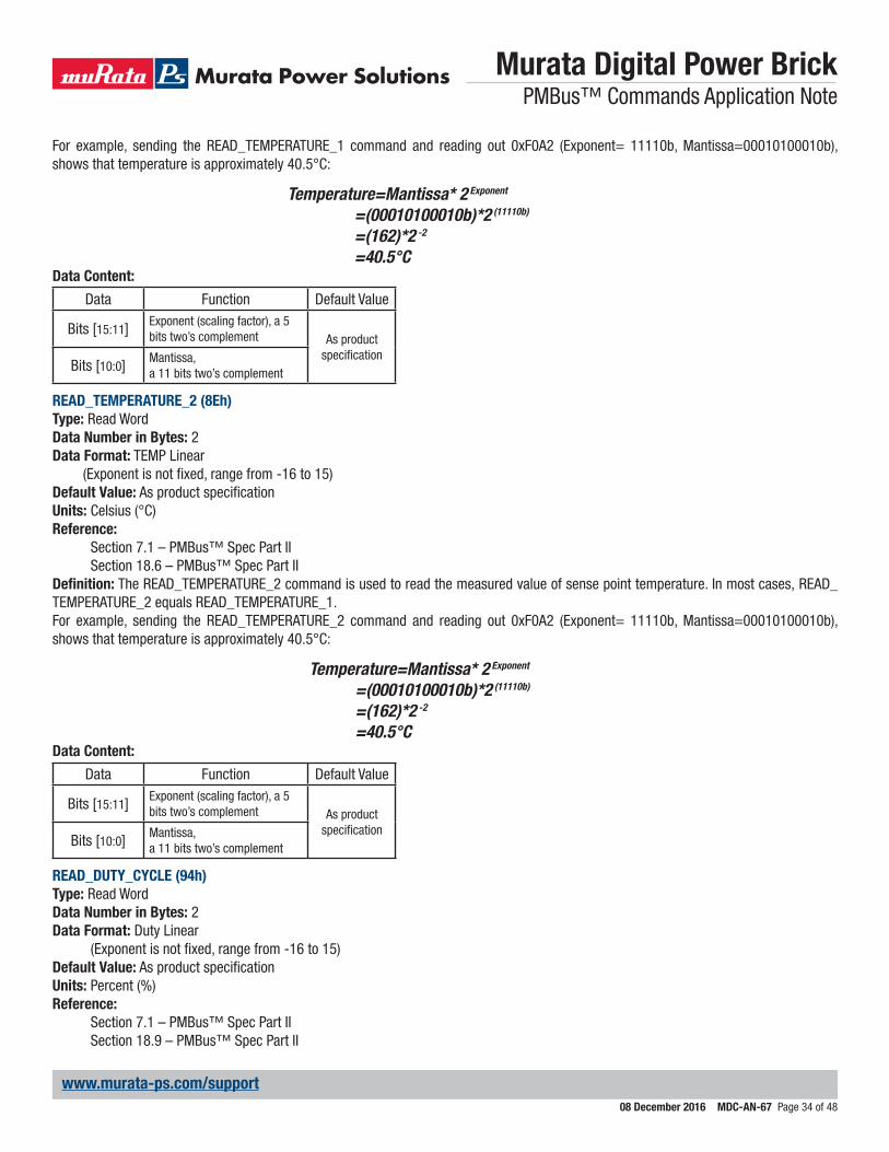
Murata Digital Power Brick PMBus™ Commands Application Note
08 December 2016 MDC-AN-67 Page 34 of 48
www.murata-ps.com/support
For example, sending the READ_TEMPERATURE_1 command and reading out 0xF0A2 (Exponent= 11110b, Mantissa=00010100010b), shows that temperature is approximately 40.5°C:
Temperature=Mantissa* 2 Exponent
=(00010100010b)*2 (11110b)
=(162)*2 -2
=40.5°CData Content:
Data Function Default Value
Bits [15:11] Exponent (scaling factor), a 5 bits two’s complement As product
specificationBits [10:0] Mantissa,
a 11 bits two’s complement
READ_TEMPERATURE_2 (8Eh)Type: Read WordData Number in Bytes: 2Data Format: TEMP Linear
(Exponent is not fixed, range from -16 to 15)Default Value: As product specificationUnits: Celsius (°C)Reference:
Section 7.1 – PMBus™ Spec Part IISection 18.6 – PMBus™ Spec Part II
Definition: The READ_TEMPERATURE_2 command is used to read the measured value of sense point temperature. In most cases, READ_TEMPERATURE_2 equals READ_TEMPERATURE_1.For example, sending the READ_TEMPERATURE_2 command and reading out 0xF0A2 (Exponent= 11110b, Mantissa=00010100010b), shows that temperature is approximately 40.5°C:
Temperature=Mantissa* 2 Exponent
=(00010100010b)*2 (11110b)
=(162)*2 -2
=40.5°CData Content:
Data Function Default Value
Bits [15:11] Exponent (scaling factor), a 5 bits two’s complement As product
specificationBits [10:0] Mantissa,
a 11 bits two’s complement
READ_DUTY_CYCLE (94h)Type: Read WordData Number in Bytes: 2Data Format: Duty Linear
(Exponent is not fixed, range from -16 to 15)Default Value: As product specificationUnits: Percent (%)Reference:
Section 7.1 – PMBus™ Spec Part IISection 18.9 – PMBus™ Spec Part II
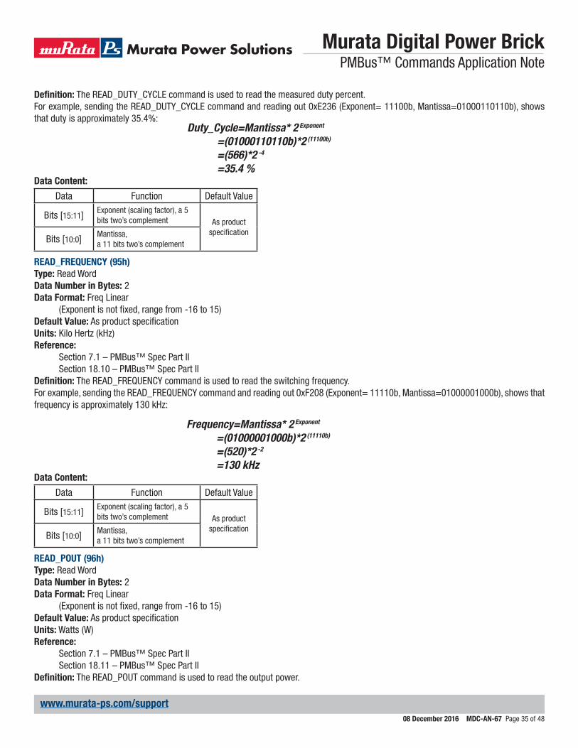
Murata Digital Power Brick PMBus™ Commands Application Note
08 December 2016 MDC-AN-67 Page 35 of 48
www.murata-ps.com/support
Definition: The READ_DUTY_CYCLE command is used to read the measured duty percent.For example, sending the READ_DUTY_CYCLE command and reading out 0xE236 (Exponent= 11100b, Mantissa=01000110110b), shows that duty is approximately 35.4%:
Duty_Cycle=Mantissa* 2 Exponent
=(01000110110b)*2 (11100b)
=(566)*2 -4
=35.4 %Data Content:
Data Function Default Value
Bits [15:11] Exponent (scaling factor), a 5 bits two’s complement As product
specificationBits [10:0] Mantissa,
a 11 bits two’s complement
READ_FREQUENCY (95h)Type: Read WordData Number in Bytes: 2Data Format: Freq Linear
(Exponent is not fixed, range from -16 to 15)Default Value: As product specificationUnits: Kilo Hertz (kHz)Reference:
Section 7.1 – PMBus™ Spec Part IISection 18.10 – PMBus™ Spec Part II
Definition: The READ_FREQUENCY command is used to read the switching frequency.For example, sending the READ_FREQUENCY command and reading out 0xF208 (Exponent= 11110b, Mantissa=01000001000b), shows that frequency is approximately 130 kHz:
Frequency=Mantissa* 2 Exponent
=(01000001000b)*2 (11110b)
=(520)*2 -2
=130 kHzData Content:
Data Function Default Value
Bits [15:11] Exponent (scaling factor), a 5 bits two’s complement As product
specificationBits [10:0] Mantissa,
a 11 bits two’s complement
READ_POUT (96h)Type: Read WordData Number in Bytes: 2Data Format: Freq Linear
(Exponent is not fixed, range from -16 to 15)Default Value: As product specificationUnits: Watts (W)Reference:
Section 7.1 – PMBus™ Spec Part IISection 18.11 – PMBus™ Spec Part II
Definition: The READ_POUT command is used to read the output power.
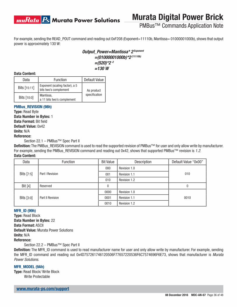
Murata Digital Power Brick PMBus™ Commands Application Note
08 December 2016 MDC-AN-67 Page 36 of 48
www.murata-ps.com/support
For example, sending the READ_POUT command and reading out 0xF208 (Exponent=11110b, Mantissa= 01000001000b), shows that output power is approximately 130 W:
Output_Power=Mantissa* 2 Exponent
=(01000001000b)*2 (11110b)
=(520)*2 -2
=130 WData Content:
Data Function Default Value
Bits [15:11] Exponent (scaling factor), a 5 bits two’s complement As product
specificationBits [10:0] Mantissa,
a 11 bits two’s complement
PMBus_REVISION (98h)Type: Read ByteData Number in Bytes: 1Data Format: Bit fieldDefault Value: 0x42Units: N/AReference:
Section 22.1 – PMBus™ Spec Part IIDefinition: The PMBus_REVISION command is used to read the supported revision of PMBus™ for user and only allow write by manufacturer.For example, sending the PMBus_REVISION command and reading out 0x42, shows that supported PMBus™ revision is 1.2.Data Content:
Data Function Bit Value Description Default Value “0x00”
Bits [7:5] Part I Revision
000 Revision 1.0
010001 Revision 1.1
010 Revision 1.2
Bit [4] Reserved 0 0
Bits [3:0] Part II Revision
0000 Revision 1.0
00100001 Revision 1.1
0010 Revision 1.2
MFR_ID (99h)Type: Read BlockData Number in Bytes: 22Data Format: ASCIIDefault Value: Murata Power SolutionsUnits: N/AReference:
Section 22.2 – PMBus™ Spec Part IIDefinition: The MFR_ID command is used to read manufacturer name for user and only allow write by manufacturer. For example, sending the MFR_ID command and reading out 0x4D757261746120506F77657220536F6C7574696F6E73, shows that manufacturer is Murata Power Solutions.
MFR_MODEL (9Ah)Type: Read Block/ Write Block
Write Protectable
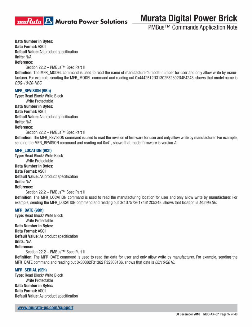
Murata Digital Power Brick PMBus™ Commands Application Note
08 December 2016 MDC-AN-67 Page 37 of 48
www.murata-ps.com/support
Data Number in Bytes:Data Format: ASCIIDefault Value: As product specificationUnits: N/AReference:
Section 22.2 – PMBus™ Spec Part IIDefinition: The MFR_MODEL command is used to read the name of manufacturer’s model number for user and only allow write by manu-facturer. For example, sending the MFR_MODEL command and reading out 0x4442512D31302F32302D4E4243, shows that model name is DBQ-10/20-NBC.
MFR_REVISION (9Bh)Type: Read Block/ Write Block
Write ProtectableData Number in Bytes:Data Format: ASCIIDefault Value: As product specificationUnits: N/AReference:
Section 22.2 – PMBus™ Spec Part IIDefinition: The MFR_REVISION command is used to read the revision of firmware for user and only allow write by manufacturer. For example, sending the MFR_REVISION command and reading out 0x41, shows that model firmware is version A.
MFR_LOCATION (9Ch)Type: Read Block/ Write Block
Write ProtectableData Number in Bytes:Data Format: ASCIIDefault Value: As product specificationUnits: N/AReference:
Section 22.2 – PMBus™ Spec Part IIDefinition: The MFR_LOCATION command is used to read the manufacturing location for user and only allow write by manufacturer. For example, sending the MFR_LOCATION command and reading out 0x4D75726174612C5348, shows that location is Murata,SH.
MFR_DATE (9Dh)Type: Read Block/ Write Block
Write ProtectableData Number in Bytes:Data Format: ASCIIDefault Value: As product specificationUnits: N/AReference:
Section 22.2 – PMBus™ Spec Part IIDefinition: The MFR_DATE command is used to read the data for user and only allow write by manufacturer. For example, sending the MFR_DATE command and reading out 0x30382F31362 F32303136, shows that date is 08/16/2016.
MFR_SERIAL (9Eh)Type: Read Block/ Write Block
Write ProtectableData Number in Bytes:Data Format: ASCIIDefault Value: As product specification
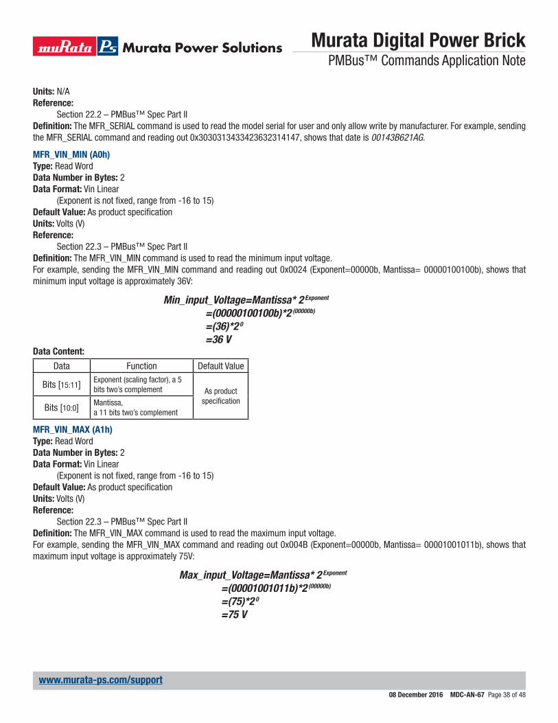
Murata Digital Power Brick PMBus™ Commands Application Note
08 December 2016 MDC-AN-67 Page 38 of 48
www.murata-ps.com/support
Units: N/AReference:
Section 22.2 – PMBus™ Spec Part IIDefinition: The MFR_SERIAL command is used to read the model serial for user and only allow write by manufacturer. For example, sending the MFR_SERIAL command and reading out 0x3030313433423632314147, shows that date is 00143B621AG.
MFR_VIN_MIN (A0h)Type: Read WordData Number in Bytes: 2Data Format: Vin Linear
(Exponent is not fixed, range from -16 to 15)Default Value: As product specificationUnits: Volts (V)Reference:
Section 22.3 – PMBus™ Spec Part IIDefinition: The MFR_VIN_MIN command is used to read the minimum input voltage.For example, sending the MFR_VIN_MIN command and reading out 0x0024 (Exponent=00000b, Mantissa= 00000100100b), shows that minimum input voltage is approximately 36V:
Min_input_Voltage=Mantissa* 2 Exponent
=(00000100100b)*2 (00000b)
=(36)*2 0 =36 V
Data Content:
Data Function Default Value
Bits [15:11] Exponent (scaling factor), a 5 bits two’s complement As product
specificationBits [10:0] Mantissa,
a 11 bits two’s complement
MFR_VIN_MAX (A1h)Type: Read WordData Number in Bytes: 2Data Format: Vin Linear
(Exponent is not fixed, range from -16 to 15)Default Value: As product specificationUnits: Volts (V)Reference:
Section 22.3 – PMBus™ Spec Part IIDefinition: The MFR_VIN_MAX command is used to read the maximum input voltage.For example, sending the MFR_VIN_MAX command and reading out 0x004B (Exponent=00000b, Mantissa= 00001001011b), shows that maximum input voltage is approximately 75V:
Max_input_Voltage=Mantissa* 2 Exponent
=(00001001011b)*2 (00000b)
=(75)*2 0 =75 V

Murata Digital Power Brick PMBus™ Commands Application Note
08 December 2016 MDC-AN-67 Page 39 of 48
www.murata-ps.com/support
Data Content:
Data Function Default Value
Bits [15:11] Exponent (scaling factor), a 5 bits two’s complement As product
specificationBits [10:0] Mantissa,
a 11 bits two’s complement
MFR_IIN_MAX (A2h)Type: Read WordData Number in Bytes: 2Data Format: Iin Linear
(Exponent is not fixed, range from -16 to 15)Default Value: As product specificationUnits: Amperes (A)Reference:
Section 22.3 – PMBus™ Spec Part IIDefinition: The MFR_IIN_MAX command is used to read the maximum input current.For example, sending the MFR_IIN_MAX command and reading out 0xE0C8 (Exponent=11100b, Mantissa=00011001000b), shows that maximum input current is approximately 12.5A:
Max_input_Current=Mantissa* 2 Exponent
=(00011001000b)*2 (11100b)
=(200)*2 -4
=12.5 AData Content:
Data Function Default Value
Bits [15:11] Exponent (scaling factor), a 5 bits two’s complement As product
specificationBits [10:0] Mantissa,
a 11 bits two’s complement
MFR_PIN_MAX (A3h)Type: Read WordData Number in Bytes: 2Data Format: Pin Linear
(Exponent is not fixed, range from -16 to 15)Default Value: As product specificationUnits: Watts (W)Reference:
Section 22.3 – PMBus™ Spec Part IIDefinition: The MFR_PIN_MAX command is used to read the maximum input power.For example, sending the MFR_PIN_MAX command and reading out 0x01C2 (Exponent=00000b, Mantissa=00111000010b), shows that maximum input power is approximately 450W:
Max_input_Power=Mantissa* 2 Exponent
=(00111000010b)*2 (00000b)
=(450)*2 0 =450 W
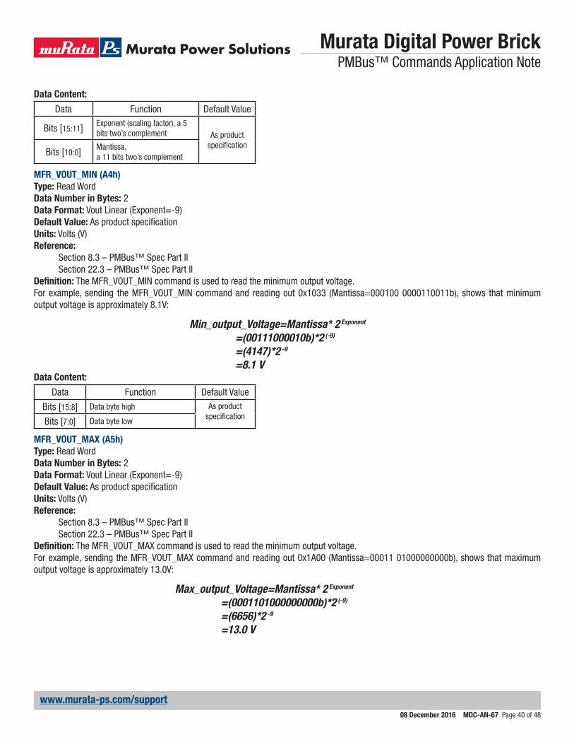
Murata Digital Power Brick PMBus™ Commands Application Note
08 December 2016 MDC-AN-67 Page 40 of 48
www.murata-ps.com/support
Data Content:
Data Function Default Value
Bits [15:11] Exponent (scaling factor), a 5 bits two’s complement As product
specificationBits [10:0] Mantissa,
a 11 bits two’s complement
MFR_VOUT_MIN (A4h)Type: Read WordData Number in Bytes: 2Data Format: Vout Linear (Exponent=-9)Default Value: As product specificationUnits: Volts (V)Reference:
Section 8.3 – PMBus™ Spec Part IISection 22.3 – PMBus™ Spec Part II
Definition: The MFR_VOUT_MIN command is used to read the minimum output voltage.For example, sending the MFR_VOUT_MIN command and reading out 0x1033 (Mantissa=000100 0000110011b), shows that minimum output voltage is approximately 8.1V:
Min_output_Voltage=Mantissa* 2 Exponent
=(00111000010b)*2 (-9)
=(4147)*2 -9
=8.1 VData Content:
Data Function Default Value
Bits [15:8] Data byte high As product specificationBits [7:0] Data byte low
MFR_VOUT_MAX (A5h)Type: Read WordData Number in Bytes: 2Data Format: Vout Linear (Exponent=-9)Default Value: As product specificationUnits: Volts (V)Reference:
Section 8.3 – PMBus™ Spec Part IISection 22.3 – PMBus™ Spec Part II
Definition: The MFR_VOUT_MAX command is used to read the minimum output voltage.For example, sending the MFR_VOUT_MAX command and reading out 0x1A00 (Mantissa=00011 01000000000b), shows that maximum output voltage is approximately 13.0V:
Max_output_Voltage=Mantissa* 2 Exponent
=(0001101000000000b)*2 (-9)
=(6656)*2 -9
=13.0 V
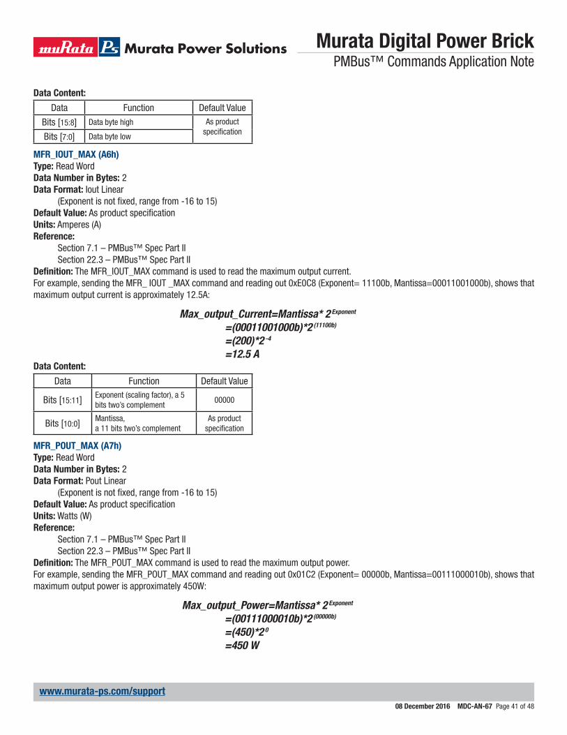
Murata Digital Power Brick PMBus™ Commands Application Note
08 December 2016 MDC-AN-67 Page 41 of 48
www.murata-ps.com/support
Data Content:
Data Function Default Value
Bits [15:8] Data byte high As product specificationBits [7:0] Data byte low
MFR_IOUT_MAX (A6h)Type: Read WordData Number in Bytes: 2Data Format: Iout Linear
(Exponent is not fixed, range from -16 to 15)Default Value: As product specificationUnits: Amperes (A)Reference:
Section 7.1 – PMBus™ Spec Part IISection 22.3 – PMBus™ Spec Part II
Definition: The MFR_IOUT_MAX command is used to read the maximum output current.For example, sending the MFR_ IOUT _MAX command and reading out 0xE0C8 (Exponent= 11100b, Mantissa=00011001000b), shows that maximum output current is approximately 12.5A:
Max_output_Current=Mantissa* 2 Exponent
=(00011001000b)*2 (11100b)
=(200)*2 -4
=12.5 AData Content:
Data Function Default Value
Bits [15:11] Exponent (scaling factor), a 5 bits two’s complement
00000
Bits [10:0] Mantissa,a 11 bits two’s complement
As product specification
MFR_POUT_MAX (A7h)Type: Read WordData Number in Bytes: 2Data Format: Pout Linear
(Exponent is not fixed, range from -16 to 15)Default Value: As product specificationUnits: Watts (W)Reference:
Section 7.1 – PMBus™ Spec Part IISection 22.3 – PMBus™ Spec Part II
Definition: The MFR_POUT_MAX command is used to read the maximum output power.For example, sending the MFR_POUT_MAX command and reading out 0x01C2 (Exponent= 00000b, Mantissa=00111000010b), shows that maximum output power is approximately 450W:
Max_output_Power=Mantissa* 2 Exponent
=(00111000010b)*2 (00000b)
=(450)*2 0 =450 W
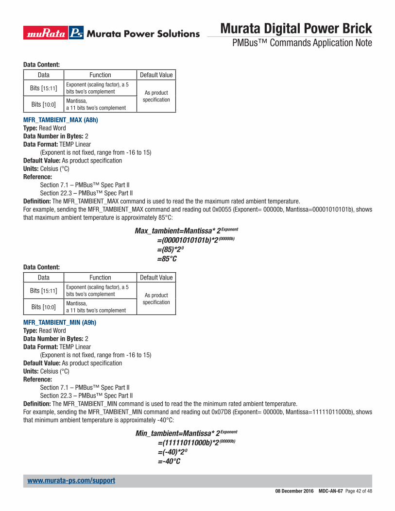
Murata Digital Power Brick PMBus™ Commands Application Note
08 December 2016 MDC-AN-67 Page 42 of 48
www.murata-ps.com/support
Data Content:
Data Function Default Value
Bits [15:11] Exponent (scaling factor), a 5 bits two’s complement As product
specificationBits [10:0] Mantissa,
a 11 bits two’s complement
MFR_TAMBIENT_MAX (A8h)Type: Read WordData Number in Bytes: 2Data Format: TEMP Linear
(Exponent is not fixed, range from -16 to 15)Default Value: As product specificationUnits: Celsius (°C)Reference:
Section 7.1 – PMBus™ Spec Part IISection 22.3 – PMBus™ Spec Part II
Definition: The MFR_TAMBIENT_MAX command is used to read the the maximum rated ambient temperature.For example, sending the MFR_TAMBIENT_MAX command and reading out 0x0055 (Exponent= 00000b, Mantissa=00001010101b), shows that maximum ambient temperature is approximately 85°C:
Max_tambient=Mantissa* 2 Exponent
=(00001010101b)*2 (00000b)
=(85)*2 0 =85°C
Data Content:
Data Function Default Value
Bits [15:11] Exponent (scaling factor), a 5 bits two’s complement As product
specificationBits [10:0] Mantissa,
a 11 bits two’s complement
MFR_TAMBIENT_MIN (A9h)Type: Read WordData Number in Bytes: 2Data Format: TEMP Linear
(Exponent is not fixed, range from -16 to 15)Default Value: As product specificationUnits: Celsius (°C)Reference:
Section 7.1 – PMBus™ Spec Part IISection 22.3 – PMBus™ Spec Part II
Definition: The MFR_TAMBIENT_MIN command is used to read the the minimum rated ambient temperature.For example, sending the MFR_TAMBIENT_MIN command and reading out 0x07D8 (Exponent= 00000b, Mantissa=11111011000b), shows that minimum ambient temperature is approximately -40°C:
Min_tambient=Mantissa* 2 Exponent
=(11111011000b)*2 (00000b)
=(-40)*2 0 =-40°C
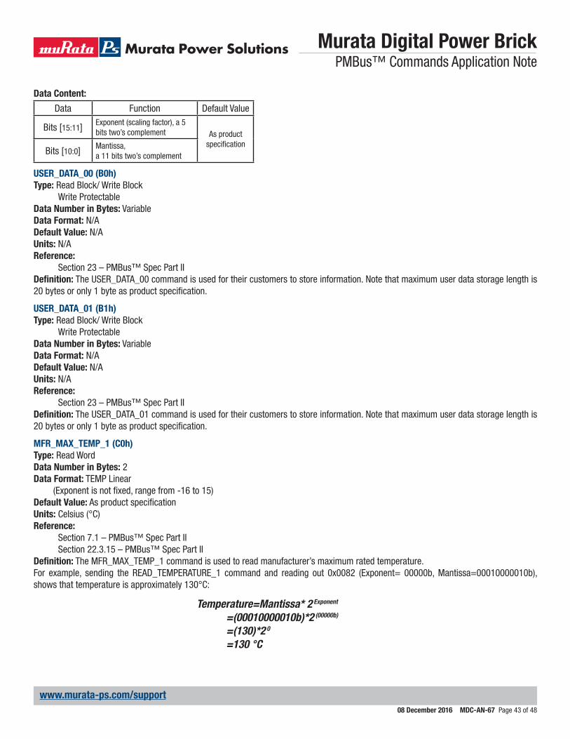
Murata Digital Power Brick PMBus™ Commands Application Note
08 December 2016 MDC-AN-67 Page 43 of 48
www.murata-ps.com/support
Data Content:
Data Function Default Value
Bits [15:11] Exponent (scaling factor), a 5 bits two’s complement As product
specificationBits [10:0] Mantissa,
a 11 bits two’s complement
USER_DATA_00 (B0h)Type: Read Block/ Write Block
Write ProtectableData Number in Bytes: VariableData Format: N/ADefault Value: N/AUnits: N/AReference:
Section 23 – PMBus™ Spec Part IIDefinition: The USER_DATA_00 command is used for their customers to store information. Note that maximum user data storage length is 20 bytes or only 1 byte as product specification.
USER_DATA_01 (B1h)Type: Read Block/ Write Block
Write ProtectableData Number in Bytes: VariableData Format: N/ADefault Value: N/AUnits: N/AReference:
Section 23 – PMBus™ Spec Part IIDefinition: The USER_DATA_01 command is used for their customers to store information. Note that maximum user data storage length is 20 bytes or only 1 byte as product specification.
MFR_MAX_TEMP_1 (C0h)Type: Read WordData Number in Bytes: 2Data Format: TEMP Linear
(Exponent is not fixed, range from -16 to 15)Default Value: As product specificationUnits: Celsius (°C)Reference:
Section 7.1 – PMBus™ Spec Part IISection 22.3.15 – PMBus™ Spec Part II
Definition: The MFR_MAX_TEMP_1 command is used to read manufacturer’s maximum rated temperature.For example, sending the READ_TEMPERATURE_1 command and reading out 0x0082 (Exponent= 00000b, Mantissa=00010000010b), shows that temperature is approximately 130°C:
Temperature=Mantissa* 2 Exponent
=(00010000010b)*2 (00000b)
=(130)*2 0 =130 °C
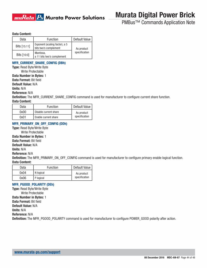
Murata Digital Power Brick PMBus™ Commands Application Note
08 December 2016 MDC-AN-67 Page 44 of 48
www.murata-ps.com/support
Data Content:
Data Function Default Value
Bits [15:11] Exponent (scaling factor), a 5 bits two’s complement As product
specificationBits [10:0] Mantissa,
a 11 bits two’s complement
MFR_CURRENT_SHARE_CONFIG (DBh)Type: Read Byte/Write Byte
Write ProtectableData Number in Bytes: 1Data Format: Bit fieldDefault Value: N/AUnits: N/AReference: N/ADefinition: The MFR_CURRENT_SHARE_CONFIG command is used for manufacturer to configure current share function.Data Content:
Data Function Default Value
0x00 Disable current share As product specification0x01 Enable current share
MFR_PRIMARY_ON_OFF_CONFIG (DDh)Type: Read Byte/Write Byte
Write ProtectableData Number in Bytes: 1Data Format: Bit fieldDefault Value: N/AUnits: N/AReference: N/ADefinition: The MFR_PRIMARY_ON_OFF_CONFIG command is used for manufacturer to configure primary enable logical function.Data Content:
Data Function Default Value
0x04 N logical As product specification0x06 P logical
MFR_PGOOD_POLARITY (DEh)Type: Read Byte/Write Byte
Write ProtectableData Number in Bytes: 1Data Format: Bit fieldDefault Value: N/AUnits: N/AReference: N/ADefinition: The MFR_PGOOD_POLARITY command is used for manufacturer to configure POWER_GOOD polarity after action.

Murata Digital Power Brick PMBus™ Commands Application Note
08 December 2016 MDC-AN-67 Page 45 of 48
www.murata-ps.com/support
Data Content:
Data Function Default Value
0x00 Enable high Level As product specification0x01 Enable low Level
MFR_VIN_OV_FAULT_HYS (E8h)Type: Read Word/Write Word
Write ProtectableData Number in Bytes: 2Data Format: TEMP Linear
(Exponent is not fixed, range from -16 to 15)Default Value: N/AUnits: Volts(V)Reference:
Section 7.1 – PMBus™ Spec Part IIDefinition: The MFR_VIN_OV_FAULT_HYS command is used for manufacturer to configure input overvoltage fault hysteresis range.Data Range: Attempt to write value outside of the acceptable range is treated as invalid data. Additionally, the value of MFR_VIN_OV_FAULT_HYS remains unchanged. Maintaining value within “acceptable range” means:Minimum clamp limit (Default in Specification) < MFR_VIN_OV_FAULT_HYS < Maximum clamp limit (Default in Specification)For example, the MFR_VIN_OV_FAULT_HYS command with the data bytes of 0xE010 (Exponent= 11100b, Mantissa=00000010000b), shows that hysteresis voltage is approximately 1V. Common range is from 0V to 2V.
Hys_Voltage=Mantissa* 2 Exponent
=(00000010000b)*2 (11100b)
=(16)*2 -4
=1 VData Content:
Data Function Default Value
Bits [15:11] Exponent (scaling factor), a 5 bits two’s complement As product
specificationBits [10:0] Mantissa,
a 11 bits two’s complement
MFR_VIN_UV_FAULT_HYS (E9h)Type: Read Word/Write Word
Write ProtectableData Number in Bytes: 2Data Format: TEMP Linear
(Exponent is not fixed, range from -16 to 15)Default Value: N/AUnits: Volts(V)Reference:
Section 7.1 – PMBus™ Spec Part IIDefinition: The MFR_VIN_UV_FAULT_HYS command is used for manufacturer to configure input voltage under voltage fault hysteresis range.Data Range: Attempt to write value outside of the acceptable range is treated as invalid data. Additionally, the value of MFR_VIN_UV_FAULT_HYS remains unchanged. Maintaining value within “acceptable range” means:Minimum clamp limit (Default in Specification) < MFR_VIN_UV_FAULT_HYS < Maximum clamp limit (Default in Specification)For example, the MFR_VIN_UV_FAULT_HYS command with the data bytes of 0xE010 (Exponent= 11100b, Mantissa=00000010000b), shows that hysteresis voltage is approximately 1V. Common range is from 0V to 2V.
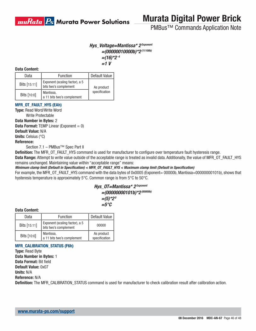
Murata Digital Power Brick PMBus™ Commands Application Note
08 December 2016 MDC-AN-67 Page 46 of 48
www.murata-ps.com/support
Hys_Voltage=Mantissa* 2 Exponent
=(00000010000b)*2 (11100b)
=(16)*2 -4
=1 VData Content:
Data Function Default Value
Bits [15:11] Exponent (scaling factor), a 5 bits two’s complement As product
specificationBits [10:0] Mantissa,
a 11 bits two’s complement
MFR_OT_FAULT_HYS (EAh)Type: Read Word/Write Word
Write ProtectableData Number in Bytes: 2Data Format: TEMP Linear (Exponent = 0)Default Value: N/AUnits: Celsius (°C)Reference:
Section 7.1 – PMBus™ Spec Part IIDefinition: The MFR_OT_FAULT_HYS command is used for manufacturer to configure over temperature fault hysteresis range.Data Range: Attempt to write value outside of the acceptable range is treated as invalid data. Additionally, the value of MFR_OT_FAULT_HYS remains unchanged. Maintaining value within “acceptable range” means:Minimum clamp limit (Default in Specification) < MFR_OT_FAULT_HYS < Maximum clamp limit (Default in Specification)For example, the MFR_OT_FAULT_HYS command with the data bytes of 0x0005 (Exponent= 00000b, Mantissa=00000000101b), shows that hysteresis temperature is approximately 5°C. Common range is from 5°C to 50°C.
Hys_OT=Mantissa* 2 Exponent
=(00000000101b)*2 (00000b)
=(5)*2 0 =5°C
Data Content:
Data Function Default Value
Bits [15:11] Exponent (scaling factor), a 5 bits two’s complement
00000
Bits [10:0] Mantissa,a 11 bits two’s complement
As product specification
MFR_CALIBRATION_STATUS (F6h)Type: Read ByteData Number in Bytes: 1Data Format: Bit fieldDefault Value: 0x07Units: N/AReference: N/ADefinition: The MFR_CALIBRATION_STATUS command is used for manufacturer to check calibration result after calibration action.
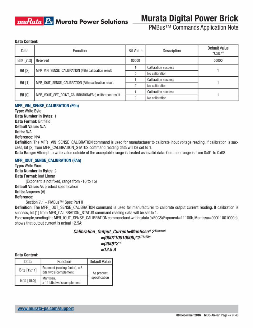
Murata Digital Power Brick PMBus™ Commands Application Note
08 December 2016 MDC-AN-67 Page 47 of 48
www.murata-ps.com/support
Data Content:
Data Function Bit Value DescriptionDefault Value
“0x07”
Bits [7:3] Reserved 00000 00000
Bit [2] MFR_VIN_SENSE_CALIBRATION (F9h) calibration result1 Calibration success
10 No calibration
Bit [1] MFR_IOUT_SENSE_CALIBRATION (FAh) calibration result1 Calibration success
10 No calibration
Bit [0] MFR_VOUT_SET_POINT_CALIBRATION(FBh) calibration result1 Calibration success
10 No calibration
MFR_VIN_SENSE_CALIBRATION (F9h)Type: Write ByteData Number in Bytes: 1Data Format: Bit fieldDefault Value: N/AUnits: N/AReference: N/ADefinition: The MFR_ VIN_SENSE_CALIBRATION command is used for manufacturer to calibrate input voltage reading. If calibration is suc-cess, bit [2] from MFR_CALIBRATION_STATUS command reading data will be set to 1.Data Range: Attempt to write value outside of the acceptable range is treated as invalid data. Common range is from 0x01 to 0x08.
MFR_IOUT_SENSE_CALIBRATION (FAh)Type: Write WordData Number in Bytes: 2Data Format: Iout Linear
(Exponent is not fixed, range from -16 to 15)Default Value: As product specificationUnits: Amperes (A)Reference:
Section 7.1 – PMBus™ Spec Part IIDefinition: The MFR_IOUT_SENSE_CALIBRATION command is used for manufacturer to calibrate output current reading. If calibration is success, bit [1] from MFR_CALIBRATION_STATUS command reading data will be set to 1.For example, sending the MFR_IOUT_SENSE_CALIBRATION command and writing data 0xE0C8 (Exponent=11100b, Mantissa=00011001000b), shows that output current is actual 12.5A:
Calibration_Output_Current=Mantissa* 2 Exponent
=(00011001000b)*2 (11100b)
=(200)*2 -4
=12.5 AData Content:
Data Function Default Value
Bits [15:11] Exponent (scaling factor), a 5 bits two’s complement As product
specificationBits [10:0] Mantissa,
a 11 bits two’s complement
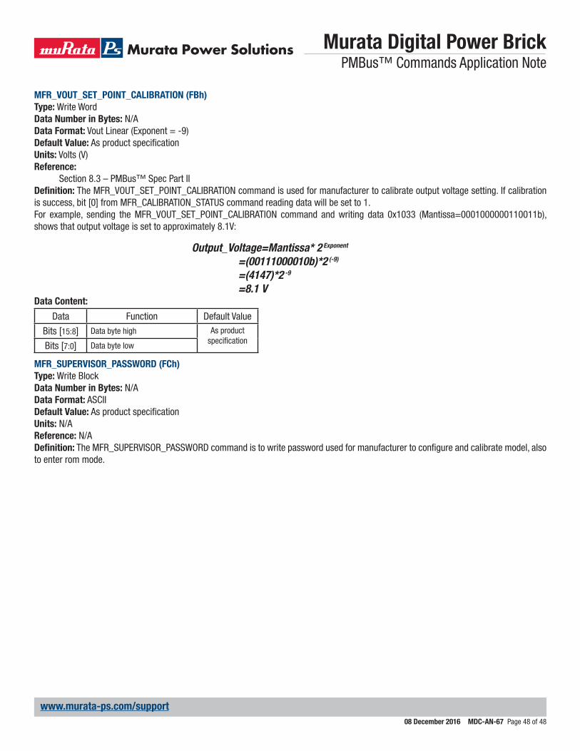
Murata Digital Power Brick PMBus™ Commands Application Note
08 December 2016 MDC-AN-67 Page 48 of 48
www.murata-ps.com/support
MFR_VOUT_SET_POINT_CALIBRATION (FBh)Type: Write WordData Number in Bytes: N/AData Format: Vout Linear (Exponent = -9)Default Value: As product specificationUnits: Volts (V)Reference:
Section 8.3 – PMBus™ Spec Part IIDefinition: The MFR_VOUT_SET_POINT_CALIBRATION command is used for manufacturer to calibrate output voltage setting. If calibration is success, bit [0] from MFR_CALIBRATION_STATUS command reading data will be set to 1.For example, sending the MFR_VOUT_SET_POINT_CALIBRATION command and writing data 0x1033 (Mantissa=0001000000110011b), shows that output voltage is set to approximately 8.1V:
Output_Voltage=Mantissa* 2 Exponent
=(00111000010b)*2 (-9)
=(4147)*2 -9
=8.1 VData Content:
Data Function Default Value
Bits [15:8] Data byte high As product specificationBits [7:0] Data byte low
MFR_SUPERVISOR_PASSWORD (FCh)Type: Write BlockData Number in Bytes: N/AData Format: ASCIIDefault Value: As product specificationUnits: N/AReference: N/ADefinition: The MFR_SUPERVISOR_PASSWORD command is to write password used for manufacturer to configure and calibrate model, also to enter rom mode.