pma7000m-s cap operation9 audio selection • com 1 and 2 are momentary buttons – receive...
TRANSCRIPT

1
Sound Quality. Sound EngineeringSound Quality. Sound Engineering..
PMA7000M-S CAP Operation
PS Engineering, Inc.PS Engineering, Inc.Prepared by Gary PicouLenoir City TN (423) [email protected]

2
PMA7000M-S Standard Versions
Standard Version PMA7000M-S
3
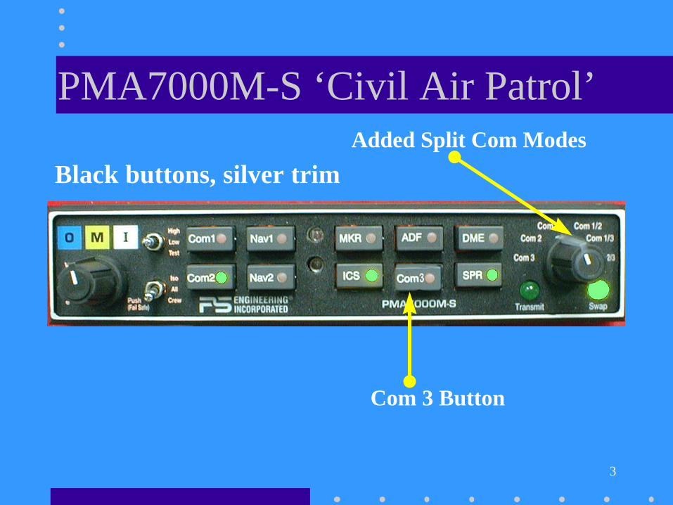
PMA7000M-S ‘Civil Air Patrol’Added Split Com Modes
Com 3 Button
Black buttons, silver trim
4
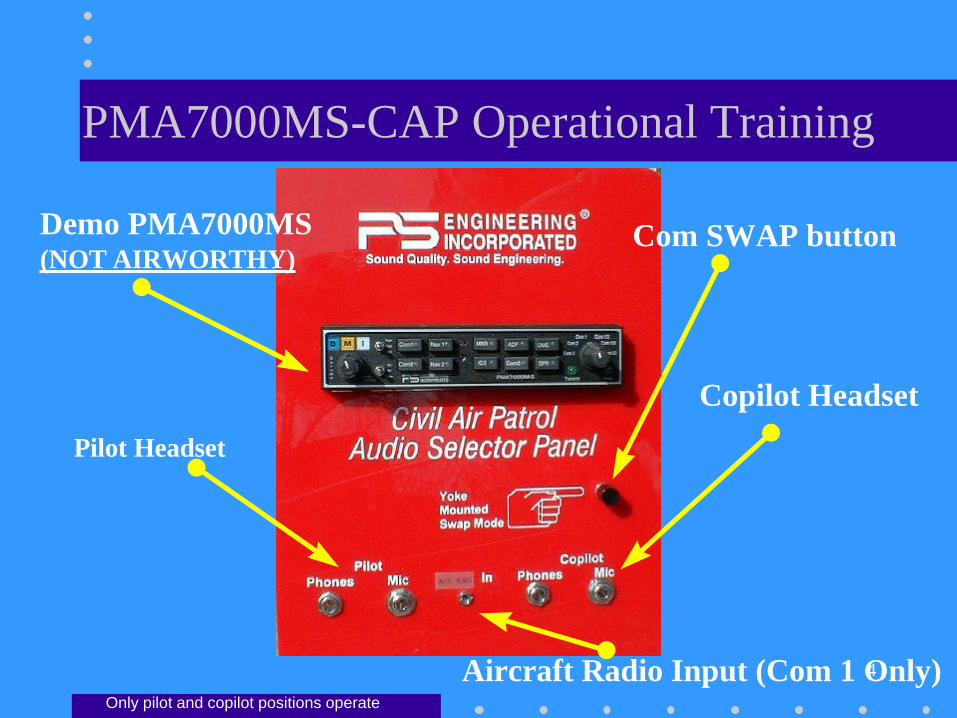
PMA7000MS-CAP Operational Training
Demo PMA7000MS(NOT AIRWORTHY)
Pilot Headset
Aircraft Radio Input (Com 1 Only)
Copilot Headset
Com SWAP button
Only pilot and copilot positions operate
5
The PMA7000M-S Features:
• Full-function audio control panel:– 3 coms, 2 navs, ADF, DME
– 3 light marker beacon receiver
• PS Engineering’s innovative:– Com1/Com2 /Com 3 Sp l it Mode for cockpit
resource management
– Swap Mode for ease of operation
– 6-pole filtered mic circuits for less noise, betterclarity

6
Revolutionary Intercom• All, ISO and Crew modes• 6-Place StereoStereo intercom
– Dual, independent auxiliary inputs
• Introducing IntelliVox™– Six INDEPENDENT mic sampling circuits
– Constantly monitoring and adjusting VOX level
– Field proven in helicopters and high noise cockpits
– NO MANUAL ADJUSTMENT -EVER-

7
Basic Operation
• Push Volume Control to switch on– Unless in Com 3 mode, at least one com LED
will light.
– Backlighting comes on
• Push Volume control to switch off– Fail Safe mode places pilot on Com 1
– Copilot/passengers have no audio
• Intercom operation: Just talk
8
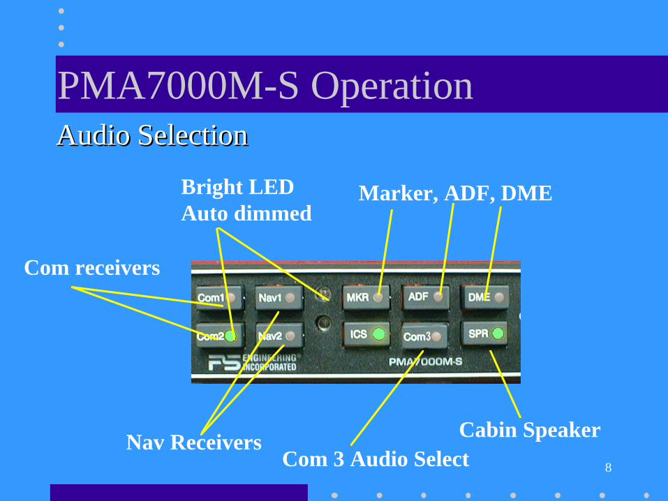
PMA7000M-S OperationAudio SelectionAudio Selection
Com receivers
Nav Receivers
Marker, ADF, DME
Cabin Speaker
Bright LED Auto dimmed
Com 3 Audio Select

9
Audio Selection• COM 1 and 2 are momentary buttons
– Receive audio always follows the Mic selector– Push button to add other com receive audio
• Com 3 audio is latched• Push Com 1, Com 2 and /or Com 3 to monitor
• Receiver buttons latch– Positive indication of the selected audio– LEDs also annunciate audio sources selected
• SPR button places all selected audioin cabin speaker

10
Transmitter SelectionSPLIT MODEPilot on Com 1Copilot on Com 2
SPLIT MODEPilot on Com 1Copilot on Com 3
Yoke Mounted SWAPreverses the indicated selection
Pilot and Copilot on Com 1
Pilot and Copilot on Com 2
Pilot and Copilot on Com 3
Transmit Indicator
SPLIT MODEPilot on Com 2Copilot on Com 3
11
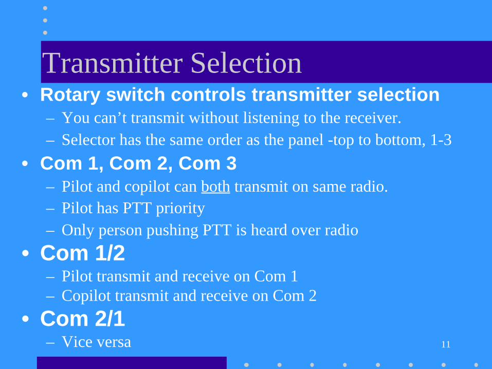
Transmitter Selection• Rotary switch controls transmitter selection
– You can’t transmit without listening to the receiver.– Selector has the same order as the panel -top to bottom, 1-3
• Com 1, Com 2, Com 3– Pilot and copilot can both transmit on same radio.– Pilot has PTT priority– Only person pushing PTT is heard over radio
• Com 1/2– Pilot transmit and receive on Com 1– Copilot transmit and receive on Com 2
• Com 2/1– Vice versa

12
CAP Transmitter CombinationsNormal Swap
Mic Se-lector
Pilot Copilot Pilot Copilot
Com 1 Com 1 Com 1 Com 2 Com 2Com 2 Com 2 Com 2 Com 1 Com 1Com 3 Com 3 Com 3 No Swap No Swap
Com1/2 Com 1 Com 2 Com 2 Com 1Com 1/3 Com 1 Com 3 Com 3 Com 1Com 2/3 Com 2 Com 3 Com 3 Com 2If the Com 3 button is pushed in a Com 3 split mode, the pilotwill also hear Com 3 audio, but no transmit.
Pushing SWAP again, or moving MIC Selector cancels swap

13
Who’s talking now?
• Com 1 or Com 2 annunciator flashesto show which radio is transmitting.
• Pilot hears selected receive audio insplit mode
• If Com 3 is selected he will hear it insplit, and can elect to monitor Com 3receptions

14
Three transmit positions
• Through an external switch someaircraft can be configured toexchange the copilot connectionwith the observer position.
• Gives observer position any radiotransmit ability.
• Copilot becomes passenger

15
Split Mode Limitations• Two comms transmitting
in close proximity maybleed over.
• Depends on:– Emission (AM/FM=Better)
– Frequency (> Difference=Better)
– Transmit Power (lower=Better)
– Antenna location(Farther=Better)

16
Squelch
Intercom FunctionsIntercom Volume CW=Increase
Mode Select
ISOISO Pilot in commandAllAll Everybody tunes inCrewCrew Front vs. back
ICS ButtonActivates Intercom in Split Modes
Aux muting Control
IntelliVox™
IntelliVox™
Dual Independent Auxiliary InputsFront and back are separated.

17
Intercom Functions• Volume Control
– Only affects the intercom level.• Not , auxiliary not radio.
– Intercom volume control for pilot and copilot only• Rear passengers are fixed volume.
• Stereo headsets have individual volume controls, can beadjusted with screwdriver.
• Push on/Push off switch– Fail-Safe mode connects pilot headset to Com 1 if
unit off, or power removed.

18
Intercom Modes
• ISO– Pilot only hears
radios
– Copilot andpassengers haveintercom
– Copilot hearsAux 1
– Passengers hearAux 2
• ALL– Everybody
hearseverything
– Radios
– Intercom
– Pilot andcopilot hearAux 1
– Passengers hearAux 2
• Crew– Pilot & Copilot
hear radios
– Pilot andcopilot haveseparateintercom
– Passengers haveintercom, noradios.
– Crew- Aux 1
– Passengers-Aux 2

19
IntelliVox ™•• RevolutionaryRevolutionary microprocessor system
– No manual control
– 6-independent circuits
– constant monitoring
• Just speak normally– Position microphone close to your lips
– Use a microphone muff
– Avoid direct drafts into microphone
– More noise the better it works

20
Intercom Entertainment• Aux source #1 feeds pilot and
copilot headset.– is muted whenever the intercom or radios are
active.
• Push “ICS” button to disable mutingof the auxiliary inputs
• Aux 2 feeds rear 4 seats.– External switch in rear of aircraft to control
Aux 2 muting
ICS

21
Marker Beacon Receiver3-lights: OOuter, MMiddle and IInner
Audio SelectionMarker Modes
HighHigh SenseLowLow SenseTestTest Lamps and receiver

22
Marker Beacon Operation
• Receiver always on.• Select MKR for receiver audio.• High sense until tone acquired.
– Select low sense if desired to precise stationcrossing indication.
• Test function for lamps and audiocircuits.

23
PTT ICS• Push to talk intercom (PTT)
– For very noisy conditions
– Only for pilot and copilot positions
– Must install ICS PTT button at each position
• PTT-Enable select switch on panel– Forces IntelliVox squelch closed
– Then use ICS PTT to be heard on intercom

24
Night time dimming
• The backlighting is adjusted by theaircraft dimmer OR– Set at a fixed level at installation.
• Annunciators and Marker lampscontrolled by photocell on unit.– The photodetector has a delay for smooth
transition

25
ProSupport Customer Care• Questions or Comments or Problems :
– Call PS Engineering at (423) 988-98008:00 am to 5:00 p.m. Eastern time.
– FAX: (423) 988-6619 any time
– email: [email protected] [email protected]
• 3-Year warranty– Replacement for first 12 months
– Repair for following 24 months

26
From all of us at PS Engineering. . .
THANK YOU !
THANK YOU !
THANK YOU !
THANK YOU !