pm 801 - olligmu.org
TRANSCRIPT

PM 801Personal Mixer

1. Read these instructions before operating this apparatus.
2. Keep these instructions for future reference.
3. Heed all warnings to ensure safe operation.
�. Follow all instructions provided in this document.
�. Do not use this apparatus near water or in locations where condensation may occur.
6. Clean only with dry cloth. Do not use aerosol or liquid cleaners. Unplug this apparatus before cleaning.
7. Do not block any of the ventilation openings. Install in accordance with the manufacturer’s instructions.
8. Do not install near any heat sources such as radiators, heat registers, stoves, or other apparatus (including
.
9. Do not defeat the safety purpose of the polarized or grounding-type plug. A polarized plug has two blades with one wider than the other. A grounding type plug has two blades and a third grounding prong. The wide blade or the third prong is provided for your safety. If the provided plug does not into your outlet, consult an electrician for replacement of the obsolete outlet.
10. Protect the power cord from being walked on or pinched particularly at plug, convenience receptacles, and the point where they exit from the apparatus.
11. Only use attachments/accessories by the manufacturer.
12. Use only with a cart, stand, tripod, bracket, or table by the manufacturer, or sold with the apparatus. When a cart is used, use caution when moving the cart/apparatus combination to avoid injury from tip-over.
13. Unplug this apparatus during lighting storms or when unused for long periods of time.
1�. Refer all servicing to service personnel. Servicing is required when the apparatus has been damaged in any way, such as power-supply cord or plug is damaged, liquid has been spilled or objects have fallen into the apparatus, the apparatus has been exposed to rain or moisture, does not operate normally, or has been dropped.
IMPORTANT SAFETY INSTRUCTIONS
CAUTION: TO REDUCE THE RISK OF ELECTRIC SHOCK,DO NOT REMOVE COVER (OR BACK)
NO USER SERVICEABLE PARTS INSIDEREFER SERVICING TO QUALIFIED PERSONNEL
The lightning flash with arrowhead symbol, within an
equilateral triangle, is intended to alert the user to the
presence of uninsulated “dangerous voltage” within the
product’
magnitude to constitute a risk of electric shock to persons.
The exclamation point within an equilateral triangle is in-
tended to alert the user to the presence of important operat-
ing and maintenance (servicing) instructions in the literature
accompanying the appliance.
WARNING: To reduce the risk of or electric shock, do not expose this apparatus to rain or moisture.
CAUTION: Use of controls or adjustments or performance of procedures other than those may result in hazardous radiation exposure.
The apparatus shall not be exposed to dripping or splashing and that no objects with liquids, such as vases, shall be placed on the apparatus. The MAINS plug is used as the disconnect device, the disconnect device shall remain readily operable.
Warning: the user shall not place this apparatus in the area during the operation so that the mains switch can be easily accessible.
CAUTIONRISK OF ELECTRIC SHOCK
DO NOT OPEN

INTRODUCTION ���������������������������������������������������������������������������4
FEATURES������������������������������������������������������������������������������������4
BASIC SETUP ������������������������������������������������������������������������������5
MAKING CONNECTIONS ������������������������������������������������������������6
CONTROLS AND SETTINGS �������������������������������������������������������7
APPLICATION �������������������������������������������������������������������������������8
DIMENSIONS ��������������������������������������������������������������������������������9
SPECIFICATIONS �����������������������������������������������������������������������10
Phonic preserves the right to improve or alter any information within this document without prior notice. V1.1 SEP 19th,2008
PM 801Personal Mixer

� PM 801
INTRODUCTIONThank you for choosing one of Phonic’s many quality mixers. The PM 801 Personal Mixer – designed by the ingenious engineers that have created a variety of mixers fantastic in style and performance in the past – is an ingenious device, with the ability to be stacked along side your other rack-mountable gear – signal processors and such – this 1 U mixer is the ideal addition to your studio rack or permanent, live setup. With 8 input channels (with XLR and 1/�" jacks), a prefader out and auxiliary in, as well as tone control and muting on each, individual channel, the PM 801 will undoubtedly prove itself to have been a valuable investment.
Before you get started, we strongly urge you to take a look through this manual. Inside, you will find many important notes on the set up, use and applications of your brand new mixer (as well as a few warnings). If you do happen to be one of the many people who flatly refuse to read user manuals, then we just urge you to at least glance at the Instant Setup section for some quick tips to get you started. After reading through the manual, it is suggested that you store it in a place that is easy for you to find, because chances are there’s something you missed the first time around.
FEATURES● 1U, compact design 8-ch mixer with EQ
● 8-Channel MIC / LINE input, each with ultra low noise preamp circuitry offering up to 62 dB gain (mic in)
● Eight sets of balanced XLR mic inputs and 1/�” unbalanced line inputs
● Pre-fader out and Aux Bus in for connecting additional units to maximize the application flexibility
● Mute control on each channel
● Clip indicator on each channel
● Tone control on each input channel
● Eight DIP switch offering real �8V phantom power for stable, full performance
● Built in power supply, no lousy wall-wart plug

�PM 801
BASIC SETUPGetting Started1. Ensure all power is turned off on the PM 801
Personal Mixer. To totally ensure this, the AC cable should not be connected to the unit.
2. All level controls should be set at all the way to the left and all channels muted to ensure no sound is inadvertently sent through the outputs when the device is switched on. All levels can be changed to acceptable degrees after the device is turned on.
3. Plug all necessary instruments and equipment into the device's various inputs as required. This may include line level devices, as well as microphones and/or guitars, keyboards, etc.
�. Plug any necessary equipment into the PM 801’s output jack and pre-fader output. These outputs can be sent to various devices, such as amplifiers, active speakers or monitors, signal processors, and/or recording devices.
�. Plug the supplied AC cable into the AC inlet on the back of the device ensuring the local voltage level is identical to that required on your device.
6. Plug the supplied AC cable into a power outlet of a suitable voltage.
7. Turn the power switch on.
Channel Setup1. To ensure the correct audio levels of each
input channel is selected, every channel should first be muted and all VRs turned all the way to the left (including the main output control).
2. Choose the channel that you wish to set the level of, and ensure that channel has a signal sent to it similar to the signal that will be sent when in common use. For example, if the channel is using a microphone, then you should speak or sing at the same level the performer normally would during a performance. If a guitar is plugged into that channel, then the guitar should also be used as it normally would be.
�. Set the level control of the selected channel to a level that allows the clip LED to illuminate occasionally; then turn it back slightly to ensure the LED does not illuminate. This will allow you to make full use of the channel’s signal.
�. This channel is now ready to be used; you can stop making the test audio signal.
6. To activate the channel, release the mute button.
7. You should now select the next channel to set and go back to follow steps 1 through �.
Note: it is possible to connect two PM 801’s together through the Prefader Outputs and AUX Bus Inputs of each, allowing a total of 16 inputs to be used, all controlled through a single fader (or both faders, and sending the same signal to 2 separate external devices).

6 PM 801
5� Prefader OutputThis RCA output allows external devices to be connected to the PM 801. Such devices may include tape recorders, signal processors and other PM 801s.
6� +48V Phantom PowerThese switches allow you to individually elect which channel's microphone input jack to active phantom power on. When activated, these switches provide +�8V of phantom power to the XLR connectors, allowing condenser microphones to be used on these channels. Before turning Phantom Power on, ensure level controls are set to a minimum.
NB. Phantom Power should be used in conjunction with balanced microphones. When Phantom Power is engaged, single ended (unbalanced) microphones and instruments should not be used on the Mic inputs. Phantom Power will not cause damage to most dynamic microphones, however if unsure, the microphone’s user manual should be consulted.
7� Power Connector and Fuse HolderThis port is for the addition of a power cable and supply, allowing power to be supplied to the mixer. Please use the power cable that is included with this mixer only. The Fuse holder, located above the AC Power connector, is, of course, for the PM 801’s fuse. If the fuse happens to blow, open the holder cover, and replace the fuse with a suitable replacement (as indicated on the fuse holder’s cover).
MAKING CONNECTIONS1� XLR Jacks These jacks accept XLR inputs for balanced signals. They can be used in conjunction with microphones, such as professional condenser, dynamic or ribbon microphones - with standard XLR male connectors. With low noise preamplifiers, these inputs serve for crystal clear sound replication.
NB. When using an unbalanced microphone, please ensure phantom power is switched off. However, when using condenser microphones the phantom power should be activated.
2� Line In JacksThese inputs accept 1/�" TS line inputs for the addition of various music instruments – such as keyboards, drum machines, electric guitars, as well as a variety of other line level instruments.
3� Aux Bus InputThis RCA input allows external devices to be connected to the PM 801. Such devices may include tape, CD players and other PM 801s.
4� Main OutputThis 1/4" Phone Jack will output the final line level signal sent from the main mixing bus. The primary purpose of this jack is to send the Main output to external devices such as amplifiers, active speakers, as well as other, mixers, PA systems, and a wide range of other possible signal processors.

7PM 801
CONTROLS AND SETTINGS8� Tone ControlsThis control allows users to attenuate the high or low frequency signals of the corresponding channel. By turning to the left, the low frequency sounds are reduced somewhat (and are reduced further as the control is turned further), and turning the control to the right has the same effect on high frequency sounds.
9� Clip IndicatorsThis small LED indicator will illuminate 6 dB before the signal of the channel is dynamically clipped. If it flashes it is advisable to turn the level control down somewhat to reduce the signal’s level and avoid distortion.
10� Mute ButtonsThese buttons affectively mute the corresponding channels, ensuring signals received by the channels are not sent onto the main mixing bus.
11� Channel Level ControlsThis control will alter the signal level that is sent from the corresponding channel to the main mixing bus.
12� Master Level ControlThis control is the final level control for the Main signal, sent to the Main output on the rear of the PM 801.
13� Power SwitchThis switch is used to turn the mixer on and off. Ensure you turn all level controls down before activating as to avoid any unwanted signals being sent through the output.

8 PM 801
APPLICATION

9PM 801
DIMENSIONS
10 PM 801
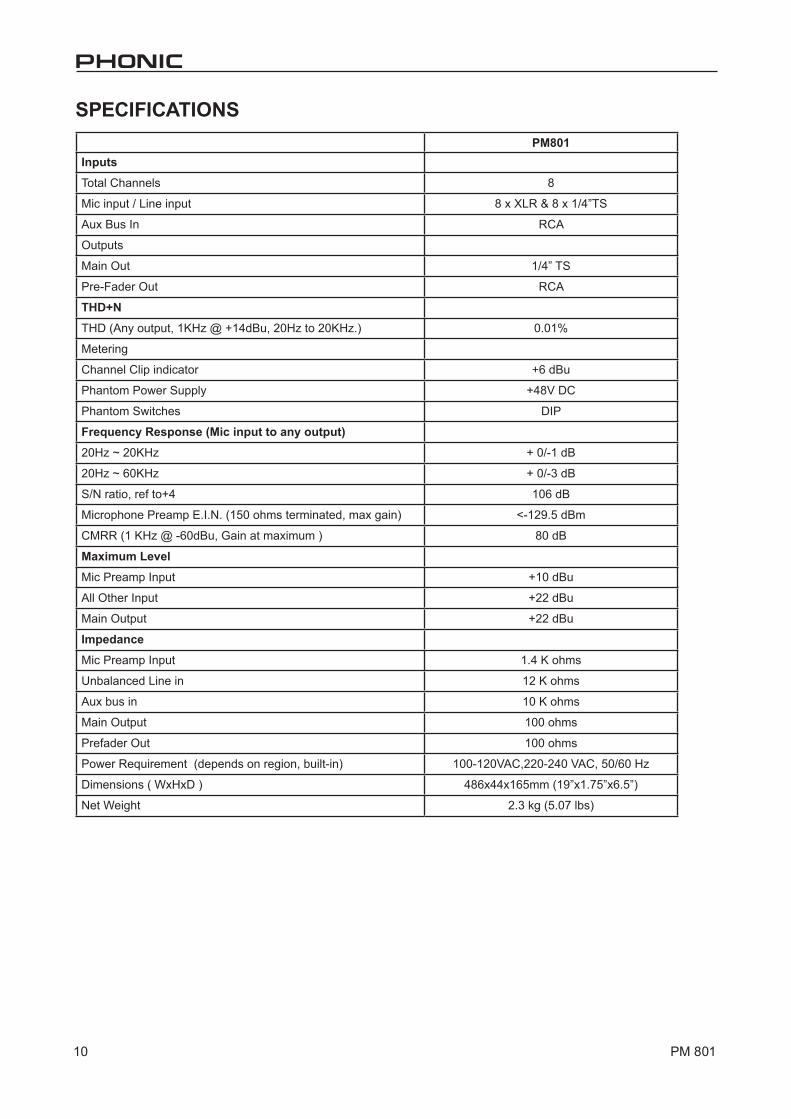
SPECIFICATIONSPM801
Inputs
Total Channels 8
Mic input / Line input 8 x XLR & 8 x 1/�”TS
Aux Bus In RCA
Outputs
Main Out 1/�” TS
Pre-Fader Out RCA
THD+N
THD (Any output, 1KHz @ +1�dBu, 20Hz to 20KHz.) 0.01%
Metering
Channel Clip indicator +6 dBu
Phantom Power Supply +�8V DC
Phantom Switches DIP
Frequency Response (Mic input to any output)
20Hz ~ 20KHz + 0/-1 dB
20Hz ~ 60KHz + 0/-3 dB
S/N ratio, ref to+� 106 dB
Microphone Preamp E.I.N. (1�0 ohms terminated, max gain) <-129.� dBm
CMRR (1 KHz @ -60dBu, Gain at maximum ) 80 dB
Maximum Level
Mic Preamp Input +10 dBu
All Other Input +22 dBu
Main Output +22 dBu
Impedance
Mic Preamp Input 1.� K ohms
Unbalanced Line in 12 K ohms
Aux bus in 10 K ohms
Main Output 100 ohms
Prefader Out 100 ohms
Power Requirement (depends on region, built-in) 100-120VAC,220-2�0 VAC, �0/60 Hz
Dimensions ( WxHxD ) �86x��x16�mm (19”x1.7�”x6.�”)
Net Weight 2.3 kg (�.07 lbs)

6103 Johns Road #7
