plus+1 guide plus+1 inverter function - danfossfiles.danfoss.com/documents/plus 1 inverter function...
TRANSCRIPT
11023441 • Rev AA • Jan 2009 1
PLUS+1TM Guide PLUS+1TM Inverter Function Block Library
PLUS+1TM Guide PLUS+1 TM Inverter Function Block Library
2 11023441 • Rev AA • Jan 2009
Revisions
History of Revisions
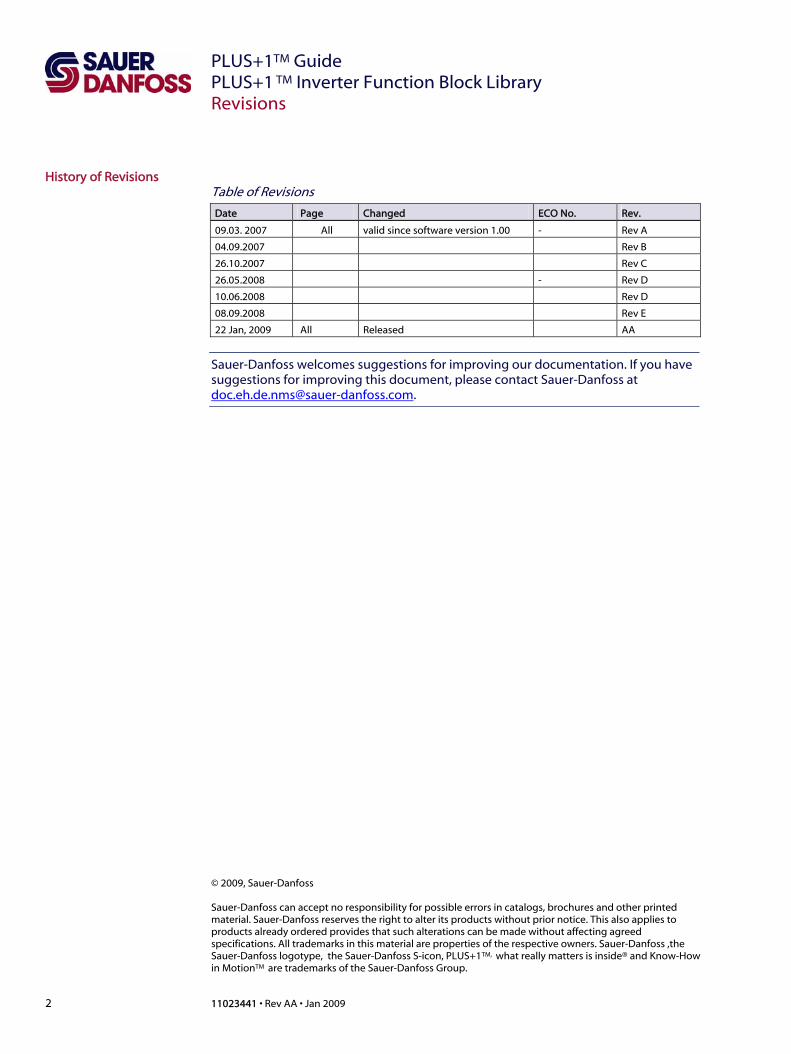
Table of Revisions
Date Page Changed ECO No. Rev.
09.03. 2007 All valid since software version 1.00 - Rev A
04.09.2007 Rev B
26.10.2007 Rev C
26.05.2008 - Rev D
10.06.2008 Rev D
08.09.2008 Rev E
22 Jan, 2009 All Released AA
Sauer-Danfoss welcomes suggestions for improving our documentation. If you have suggestions for improving this document, please contact Sauer-Danfoss at [email protected].
© 2009, Sauer-Danfoss Sauer-Danfoss can accept no responsibility for possible errors in catalogs, brochures and other printed material. Sauer-Danfoss reserves the right to alter its products without prior notice. This also applies to products already ordered provides that such alterations can be made without affecting agreed specifications. All trademarks in this material are properties of the respective owners. Sauer-Danfoss ,the Sauer-Danfoss logotype, the Sauer-Danfoss S-icon, PLUS+1TM, what really matters is inside® and Know-How in MotionTM are trademarks of the Sauer-Danfoss Group.

PLUS+1 TM Guide PLUS+1 TM Inverter Function Block Library
11023441 • Rev AA • Jan 2009 3
Contents
Analog Input 4 Analog Input............................................................................................................................................................ 4
Calibration .......................................................................................................................................................... 4 Manual Calibration.......................................................................................................................................... 4 Semi-Automatic Calibration ........................................................................................................................ 4 Semi-Automatic Calibration with enable input.................................................................................... 5 Set Defaults ........................................................................................................................................................ 5 Inputs/Outputs ................................................................................................................................................. 5 Basic Function ................................................................................................................................................... 7
Battery Discharge Indicator 8 Battery Discharge Indicator (BDI)..................................................................................................................... 8
Discharge Characteristic, Voltage per Cell ............................................................................................. 8 Inputs/Outputs ................................................................................................................................................. 9
Brake and Power 10 Brake and Power ..................................................................................................................................................10
Inputs/Outputs ...............................................................................................................................................11 Derating 13
Derating ..................................................................................................................................................................13 Inputs/Outputs ...............................................................................................................................................13
Direction Signals 14 Direction Signals ..................................................................................................................................................14
Inputs/Outputs ...............................................................................................................................................14 Dynamic Drive Curve Generator 15
DDCG........................................................................................................................................................................15 Inputs/Outputs ...............................................................................................................................................15
Error History 20 Error History...........................................................................................................................................................20
Inputs/Outputs ...............................................................................................................................................20 Error Status Handler 22
Error Status Handler............................................................................................................................................22 Inputs/Outputs ...............................................................................................................................................22
Hour Counter 25 Hour Counter.........................................................................................................................................................25
Inputs / Outputs .............................................................................................................................................25 Main Contactor 26
Main Contactor.....................................................................................................................................................26 Inputs/Outputs ...............................................................................................................................................26
Roll Off 27 Roll Off .....................................................................................................................................................................27
Inputs/Outputs ...............................................................................................................................................27 Seat Switch 30
Seat Switch.............................................................................................................................................................30 Inputs/Outputs ...............................................................................................................................................30
Service Counter 31 Service Counter ....................................................................................................................................................31
Inputs/Outputs ...............................................................................................................................................31 Shunting 32
Shunting..................................................................................................................................................................32 Inputs/Outputs ...............................................................................................................................................32
Solenoid Chopper 33 Solenoid Chopper................................................................................................................................................33
Inputs/Outputs ...............................................................................................................................................33
PLUS+1TM Guide PLUS+1 TM Inverter Function Block Library
4 11023441 • Rev AA • Jan 2009
Analog Input
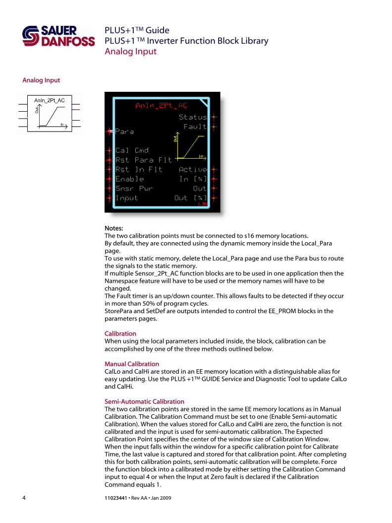
Analog Input
Notes: The two calibration points must be connected to s16 memory locations. By default, they are connected using the dynamic memory inside the Local_Para page. To use with static memory, delete the Local_Para page and use the Para bus to route the signals to the static memory. If multiple Sensor_2Pt_AC function blocks are to be used in one application then the Namespace feature will have to be used or the memory names will have to be changed. The Fault timer is an up/down counter. This allows faults to be detected if they occur in more than 50% of program cycles. StorePara and SetDef are outputs intended to control the EE_PROM blocks in the parameters pages. Calibration When using the local parameters included inside, the block, calibration can be accomplished by one of the three methods outlined below. Manual Calibration CalLo and CalHi are stored in an EE memory location with a distinguishable alias for easy updating. Use the PLUS +1TM GUIDE Service and Diagnostic Tool to update CalLo and CalHi. Semi-Automatic Calibration The two calibration points are stored in the same EE memory locations as in Manual Calibration. The Calibration Command must be set to one (Enable Semi-automatic Calibration). When the values stored for CalLo and CalHi are zero, the function is not calibrated and the input is used for semi-automatic calibration. The Expected Calibration Point specifies the center of the window size of Calibration Window. When the input falls within the window for a specific calibration point for Calibrate Time, the last value is captured and stored for that calibration point. After completing this for both calibration points, semi-automatic calibration will be complete. Force the function block into a calibrated mode by either setting the Calibration Command input to equal 4 or when the Input at Zero fault is declared if the Calibration Command equals 1.
PLUS+1 TM Guide PLUS+1 TM Inverter Function Block Library
11023441 • Rev AA • Jan 2009 5
Analog Input
Analog Input (continued) Semi-Automatic Calibration with enable input The two calibration points are stored in the same EE memory locations as in Manual Calibration. The Calibration Command must be set to two (Enable Semi-automatic Calibration with enable input). When the values stored for CalLo and CalHi are zero, the function is not calibrated and the input is used for semi-automatic calibration with enable input. The Expected Calibration Point specifies the center of the window size of Calibration Window. When the input falls within the window for a CalHi calibration point for Calibrate Time, the last value is captured and stored for that calibration point. When the input falls within the window for a CalLo calibration point and the Enable Input has a rising edge (0 -> 1) the value is captured and stored for that calibration point. After completing this for both calibration points, semi-automatic calibration will be complete. Force the function block into a calibrated mode by either setting the Calibration Command input to equal 4 or when the Input at Zero fault is declared if the Calibration Command equals 1 Set Defaults When the Calibration Command equals tree, the Set Defaults variable in the parameter bus is TRUE. If this is used as the SET_DEF inputs for the CalLo and CalHi memory blocks, then the DEF_VALUE will be stored into memory. Inputs/Outputs Inputs
Item Description/Range
Cal Cmd (0 - 4) 0: Manual calibration
1: Semi Auto Cal
2: Semi Auto Cal with enable input
3: Set Calibration values to defaults
4: Clear Calibration
Rst Para Flt (BOOL) T: Fault is not latched
F: Fault is latched until fixed and power is cycled
Rst In Flt (BOOL) T: Fault is not latched
F: Fault is latchet until fixed and power is cycled
Snsr Pwr (0 - 65535) Sensor Power in mV
Used for ratiometric calculations of calibration
points, deadbands and faults
Input (0 – 65535) Input mV
Enable (BOOL) If true and In is in CalLo win, value is saved.
Note: Only available if calibration mode = 2

PLUS+1TM Guide PLUS+1 TM Inverter Function Block Library
6 11023441 • Rev AA • Jan 2009
Analog Input
Inputs/Outputs (continued) Output
Item Description/Range
Status (U16) Standard Bitwise pattern
Fault (U16) Standard Bitwise pattern
Active (BOOL) HIGH if output is not 0
In % (U16) Percentage of input value from SnsrPwr
Out (S32) Output value scaled from LoOut to HiOut
Out % (U16) 0 to 10000 in .01%
Parameter
Item Description/Range
StorePara (BOOL) Signal used to store calibration values
SetDef (BOOL) Signal used to set default calibration values
CalLo (0 – 9999) Input value associated with output = 0
Specified by units of .01% of Snsr Pwr
CalHi (0 – 9999) Input value associated with output = 10000
Specified by units of .01% of Snsr Pwr
Fault % (0 to 10000) Input Fault Percent in .01%
A fault is declared when the input is either above
Hi Cal or below LoCal by at least
(Hi Cal-Lo Cal) * (SnsrPwr) * (Fault %)
LoOut (S32) Is the calibrated minimum value of “Out”
HiOut (S32) Is the calibrated maximum value of “Out”
DbndLo (0 – 5000) The output = 0 when the input is below
(SnsrPwr)*[Dbnd_1 + (Dbnd_1)*(CalHi - CalLo)]
Specified by units of .01% of Snsr Pwr
DbndHi (0 – 5000) The output = 10000 when the input is above
(SnsrPwr)*[CalHi – (Dbnd_2)*(CalHi – CalLo)]
Specified by units of .01% of Snsr Pwr
ExpCalLo (0 – 10000) Expected value used to determine center of
acceptable calibration window. Specified by units
of .01% of Snsr Pwr
ExpCalHi (0 – 10000) Expected value used to determine center of
acceptable calibration window. Specified by units
of .01% of Snsr Pwr
CalWin (0 – 5000) Amount +/- expected calibration points used to
determine acceptable calibration window.
Specified by units of .01% of Snsr Pwr
CalDetTm (0 – 65535) Calibration capture time in ms
FltDetTm (0 – 65535) Fault detection time in ms. The time that a fault
needs to be present before it is declared
PLUS+1 TM Guide PLUS+1 TM Inverter Function Block Library
11023441 • Rev AA • Jan 2009 7
Analog Input
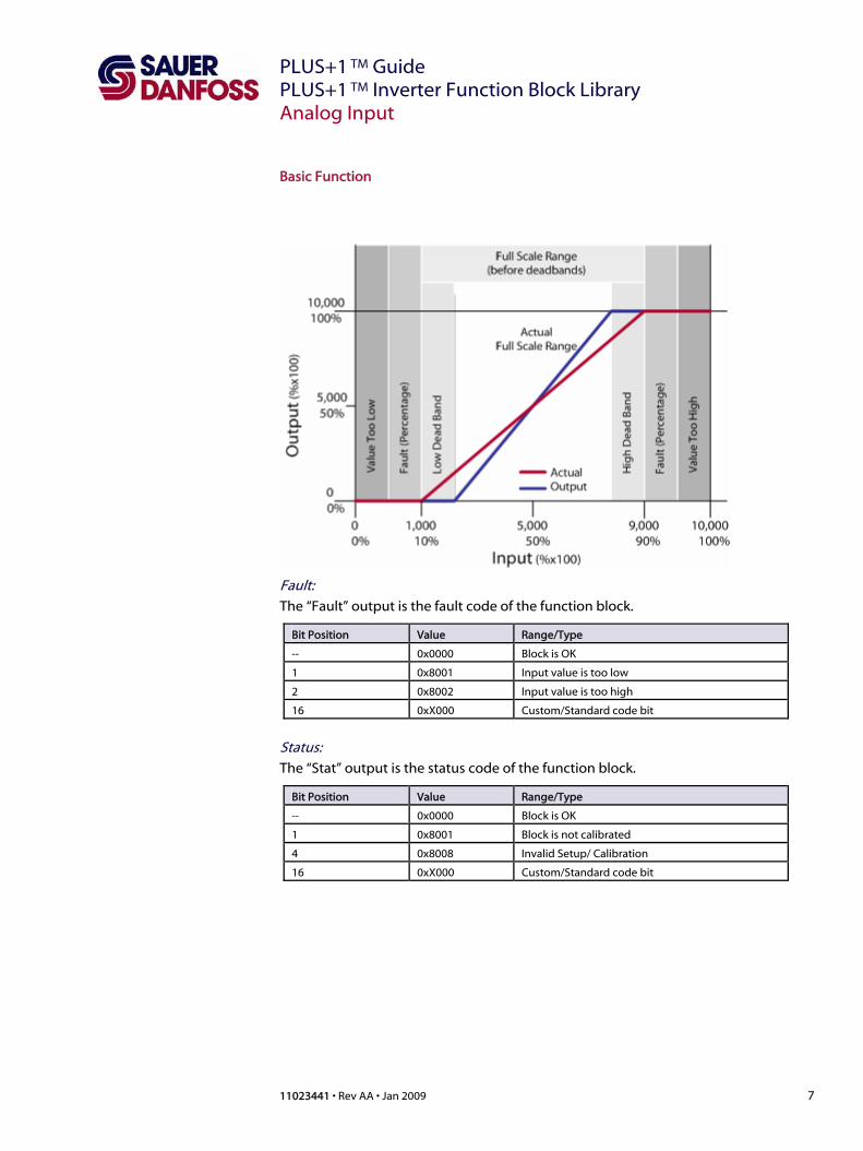
Basic Function
Fault: The “Fault” output is the fault code of the function block.
Bit Position Value Range/Type
-- 0x0000 Block is OK
1 0x8001 Input value is too low
2 0x8002 Input value is too high
16 0xX000 Custom/Standard code bit
Status: The “Stat” output is the status code of the function block.
Bit Position Value Range/Type
-- 0x0000 Block is OK
1 0x8001 Block is not calibrated
4 0x8008 Invalid Setup/ Calibration
16 0xX000 Custom/Standard code bit

PLUS+1TM Guide PLUS+1 TM Inverter Function Block Library
8 11023441 • Rev AA • Jan 2009
Battery Discharge Indicator
Battery Discharge Indicator (BDI)
The Battery Discharge Indicator (BDI) is designed to cover lead acid battery only. There are 11 discharge and one charge characteristics stored in the function block. Each characteristic consists of 10 internal voltage values. All in all 120 different threshold values are available for the calculating algorithm. The different battery types can be handled by adjusting the parameter BDI_BatteryType for the discharge characteristics. A time counter increases if the actual battery voltage is higher than the actual charge threshold and decrease if the actual battery voltage is lower than the actual discharge threshold value. If the time counter = 0 the Level decrease one step. If the time counter reaches Tmax the level increase one step. The actual threshold values are calculated out of the actual level and battery type.
Discharge Characteristic, Voltage per Cell
Type0 Type1 Type2 Type3 Type4 Type5 Type6 Type7 Type8 Type9 Type10
Charge of
battery
Level %
1,950 1,963 1,974 1,986 1,997 2,006 2,010 2,014 2,021 2,026 2,030 10 100
1,903 1,922 1,938 1,954 1,970 1,982 1,989 1,995 2,005 2,011 2,018 9 90
1,855 1,880 1,901 1,922 1,943 1,959 1,968 1,976 1,988 1,997 2,005 8 80
1,808 1,838 1,864 1,890 1,915 1,936 1,946 1,957 1,972 1,982 1,993 7 70
1,760 1,797 1,827 1,858 1,888 1,913 1,925 1,937 1,956 1,968 1,980 6 60
1,713 1,755 1,790 1,826 1,861 1,890 1,904 1,918 1,939 1,953 1,968 5 50
1,665 1,713 1,754 1,794 1,834 1,866 1,883 1,899 1,923 1,939 1,955 4 40
1,618 1,672 1,717 1,762 1,807 1,843 1,861 1,879 1,906 1,924 1,943 3 30
1,570 1,630 1,680 1,730 1,780 1,820 1,840 1,860 1,890 1,910 1,930 2 20
1,523 1,588 1,643 1,698 1,753 1,797 1,819 1,841 1,874 1,896 1,918 1 10

PLUS+1 TM Guide PLUS+1 TM Inverter Function Block Library
11023441 • Rev AA • Jan 2009 9
Battery Discharge Indicator
Inputs/Outputs Inputs
Item Description/Range
Level Init (U8) When the block is started up, this value is used to
initialize the charge level ( 1 … 10)
Note: These values need to be connected to an
EEPROM cell (NVRam Input), which is saved at
power down.
ChgCounter (U32) When the block is stated up, this value is used to
initialize the charge counter
Note: These values need to be connected to an
EEPROM cell (NVRam Input), which is saved at
power down.
RstEnblPwr (BOOL) Initiates a reset of the block at power on when the
following conditions are also fulfilled.
Level < 7
U-Batt > BDI-ResetVoltage_mV x cells
Power on
Reset (BOOL) Initiates a reset of the block
UBatt_mV (U32) Battery power in mV
Output
Item Description/Range
ChargeCount (U32) Current value of the discharge/charge timer
Note: These values need to be connected to an
EEPROM cell (NVRam Output), which is saved at
power down.
Level (U8) Current discharge level of the battery. (1 … 10)
Note: These values need to be connected to an
EEPROM cell (NVRam Output), which is saved at
power down. Parameter
Item Description/Range
NmbrCells (U8) Number of battery cells (^2 Volt/cell)
Default: 24
Tmax (U32) Time in Milliseconds between two levels.
Default: 240000 ms [ms]
ResetVoltage_mV (U16) Voltage threshold per cell
Default: 2090
(0 … 4000)
Battery Type (U8) Selection of the discharge curve
Default: 3
(0 … 10)

PLUS+1TM Guide PLUS+1 TM Inverter Function Block Library
10 11023441 • Rev AA • Jan 2009
Brake and Power
Brake and Power
The “Brake and Power” function control the electromechanical brake and the power stage, at different driving conditions. Start: If the “Enbl” signal goes active (positive edge) the power stage shall be enabled immediately, but the brake shall be opened (powered) with a time delay (BrkOpen_ms). Emergency stop (Emc): The power stage shall be disabled and the brake shall be closed immediately. Emergency stop has the highest priority. Stop ramp (Mode = 0): If the “Enbl” signal goes inactive and the stop ramp is activated. The function has to wait until the actual speed is less than a threshold value (BrkThd_rpm1) and then a time (BrkClose_ms) shall be started. After this time the brake shall be closed immediately and a second time (PwrDsbl_ms) shall be started. During this time the brake has time to close and at the end of this time the power stage shall be disabled.

PLUS+1 TM Guide PLUS+1 TM Inverter Function Block Library
11023441 • Rev AA • Jan 2009 11
Brake and Power
Brake and Power (continued) Coast (Mode = 1): If the “Enbl” signal goes inactive and the coast function is activated. The power stage shall be disabled immediately. Then the function has to wait unit the actual speed is less than a threshold value (BrkThd_rpm1) and then a time (BrkClose_ms) shall be started. After this time the brake shall be closed. At the beginning of this function, a safety time (SafTm_ms) shall be started. After this time the brake shall be disabled, in any case.
Inputs/Outputs Inputs
Item Description/Range
Enbl (BOOL) Drive enable input
Emc (BOOL) Emergency input
Spd_rpm1 (S32) Actual motor speed [0.1 rpm]
Output
Item Description/Range
Brk (BOOL) Mechanical brake output
Pwr (BOOL) Power stage enable output
PLUS+1TM Guide PLUS+1 TM Inverter Function Block Library
12 11023441 • Rev AA • Jan 2009
Brake and Power
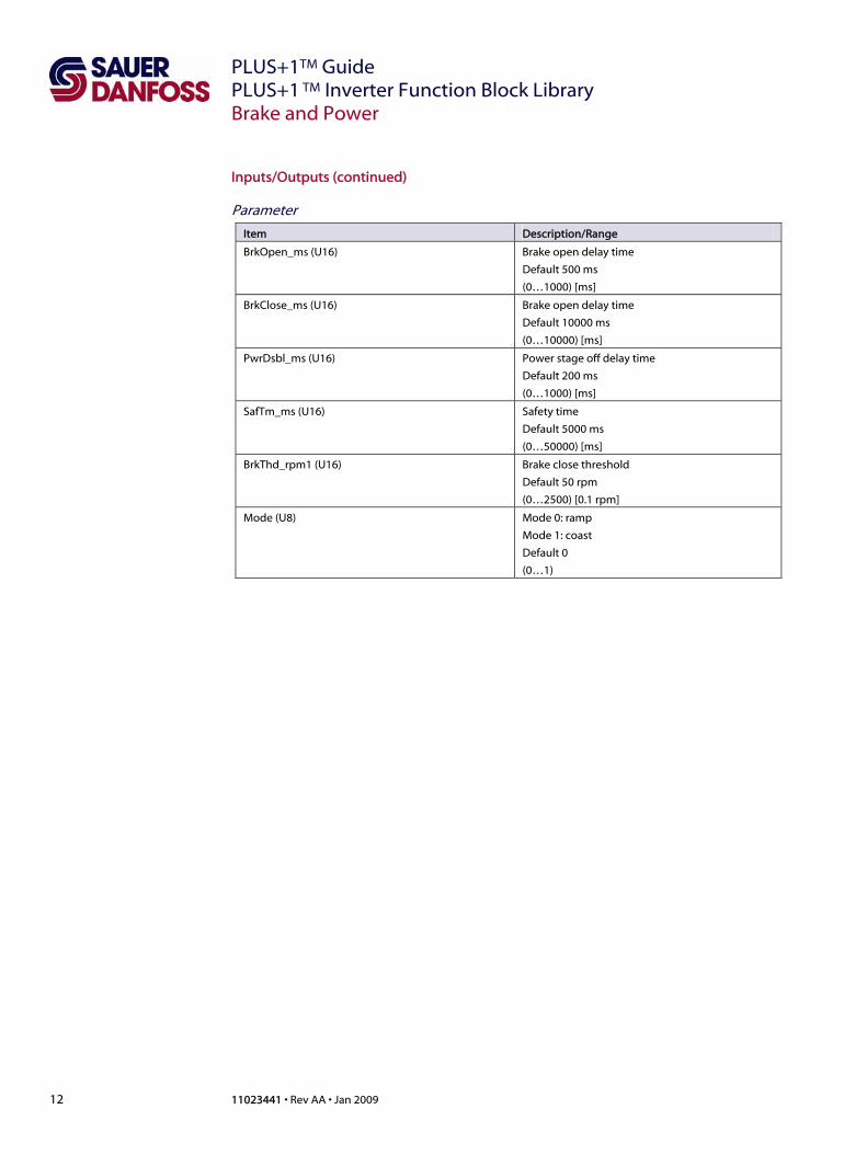
Inputs/Outputs (continued)
Parameter
Item Description/Range
BrkOpen_ms (U16) Brake open delay time
Default 500 ms
(0…1000) [ms]
BrkClose_ms (U16) Brake open delay time
Default 10000 ms
(0…10000) [ms]
PwrDsbl_ms (U16) Power stage off delay time
Default 200 ms
(0…1000) [ms]
SafTm_ms (U16) Safety time
Default 5000 ms
(0…50000) [ms]
BrkThd_rpm1 (U16) Brake close threshold
Default 50 rpm
(0…2500) [0.1 rpm]
Mode (U8) Mode 0: ramp
Mode 1: coast
Default 0
(0…1)

PLUS+1 TM Guide PLUS+1 TM Inverter Function Block Library
11023441 • Rev AA • Jan 2009 13
Derating
Derating
This function can be used for derating the max motor current dependant on the inverter temperature as well as for a derating dependant of the motor temperature. There are two separate derating curves, one for motor mode (acceleration) and one for generator mode (deceleration). If ActTemp is lower than Temp100perc, the output is at 10000 (100%) If ActTemp is higher than TempDerate the output is IDerateG (GenMode=1) or IDerateM (GenMode=0) If ActTemp is between Temp1 and Temp2 the output is reduced by a linear curve between 100% and IDerateM (GenMode=0) or IDerateG (GenMode=1) Inputs/Outputs Inputs
Item Description/Range
ActTemp [S16] Actual Temperature
GenMode [BOOL] 0/F = Motor Mode
1/T = Generator Mode
Output
Item Description/Range
Derating [U16] Derating factor (0.. 10.000) [0.01%]
Status [U8] Status of the function.
0 = Temperature ok
1 = Temperature High -> Derating starts
2 = Temperature too high -> Derating at max.
Parameter
Item Description/Range
Temp100perc [S16] Temperature at which the derating curve starts
TempDerate [S16] Temperature at which the derating curve ends
IDerateM [U16] Derated curve for motor mode [0.01%]
IDerateG [U16] Derated curve for generator mode [0.01%]

PLUS+1TM Guide PLUS+1 TM Inverter Function Block Library
14 11023441 • Rev AA • Jan 2009
Direction Signals
Direction Signals
Use the FNR Direction block to handle the forward, neutral and reverse logic of a vehicle. With the Precondition input it can be avoid, that the truck starts to move with out some start up sequence and that a rising edge (0->1) is necessary on the FWD or RWD Switch. Inputs/Outputs Inputs
Item Description/Range
PreCond (BOOL) Must be TRUE to enable Fwd and Rvs switch. Fwd
and Rvs must be FALSE to enable PreCond. If
PreCond goes to FALSE Fwd and Rvs will be
disabled
Fwd SW (BOOL) Forward switch signal
Rvs SW (BOOL) Reverse switch signal
Fdbk (S32) Must be zero before output direction can change
Fault (U16) Standard Bitwise pattern
Output
Item Description/Range
Direction (S16) -1 = Reverse
0 = Neutral
+1 = Forward
Drv Enbl (BOOL) T = Exactly one direction input is true
F = neutral or Fault
PLUS+1 TM Guide PLUS+1 TM Inverter Function Block Library
11023441 • Rev AA • Jan 2009 15
Dynamic Drive Curve Generator
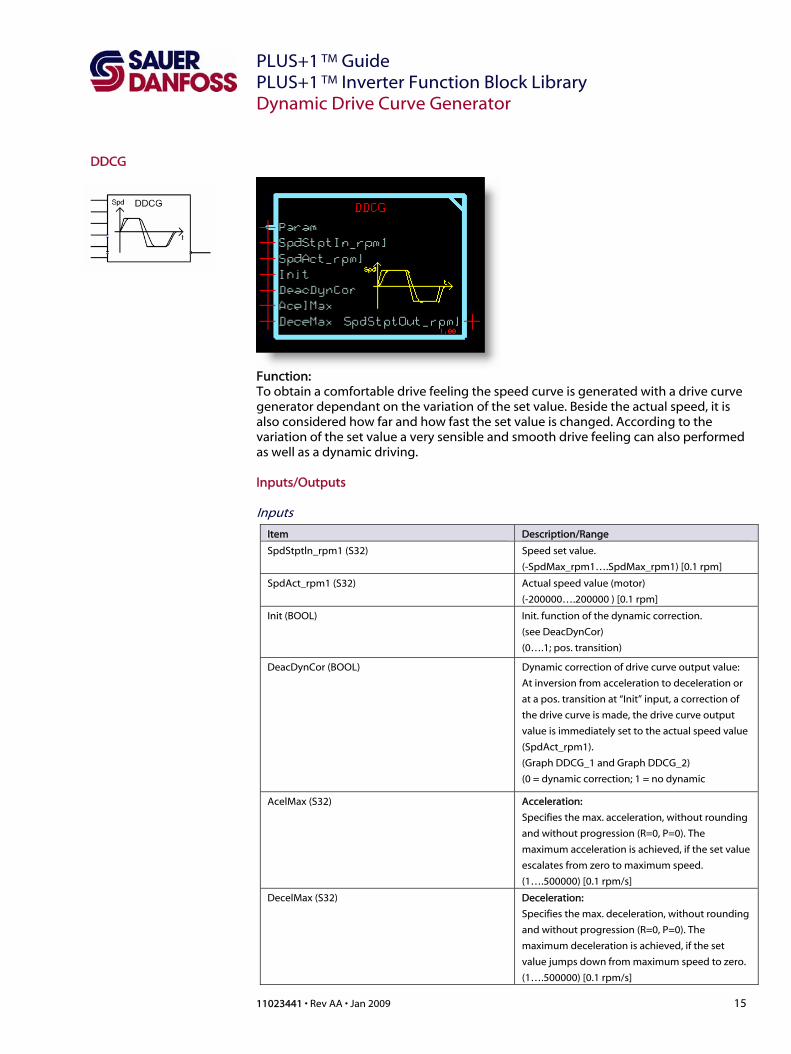
DDCG
Function: To obtain a comfortable drive feeling the speed curve is generated with a drive curve generator dependant on the variation of the set value. Beside the actual speed, it is also considered how far and how fast the set value is changed. According to the variation of the set value a very sensible and smooth drive feeling can also performed as well as a dynamic driving.
Inputs/Outputs Inputs
Item Description/Range
SpdStptln_rpm1 (S32) Speed set value.
(-SpdMax_rpm1….SpdMax_rpm1) [0.1 rpm]
SpdAct_rpm1 (S32) Actual speed value (motor)
(-200000….200000 ) [0.1 rpm]
Init (BOOL) Init. function of the dynamic correction.
(see DeacDynCor)
(0….1; pos. transition)
DeacDynCor (BOOL) Dynamic correction of drive curve output value:
At inversion from acceleration to deceleration or
at a pos. transition at “Init” input, a correction of
the drive curve is made, the drive curve output
value is immediately set to the actual speed value
(SpdAct_rpm1).
(Graph DDCG_1 and Graph DDCG_2)
(0 = dynamic correction; 1 = no dynamic
i ) AcelMax (S32) Acceleration:
Specifies the max. acceleration, without rounding
and without progression (R=0, P=0). The
maximum acceleration is achieved, if the set value
escalates from zero to maximum speed.
(1….500000) [0.1 rpm/s]
DecelMax (S32) Deceleration:
Specifies the max. deceleration, without rounding
and without progression (R=0, P=0). The
maximum deceleration is achieved, if the set
value jumps down from maximum speed to zero.
(1….500000) [0.1 rpm/s]

PLUS+1TM Guide PLUS+1 TM Inverter Function Block Library
16 11023441 • Rev AA • Jan 2009
Dynamic Drive Curve Generator
DDCG (continued) Graph DDCG_1
without correction
0
20
40
60
80
100
120
0 1 2 3 4 5 6
t/s
spee
d/%
drive curve actual speed
Decel. Delay
Graph DDCG_2
with correction
0
20
40
60
80
100
120
0 1 2 3 4 5 6t/s
spee
d/%
drive curve actual speed

PLUS+1 TM Guide PLUS+1 TM Inverter Function Block Library
11023441 • Rev AA • Jan 2009 17
Dynamic Drive Curve Generator
Inputs/Outputs (continued)
Output
Item Description/Range
SpdStptOut_rpm1 (S32) Calculated speed set value.
(-20000….200000) [0.1 rpm]
Parameter
Item Description/Range
Progression (U8) Specifies the influence of the set value variation to
the value of acceleration or deceleration.
Progression = 0: Independently of the set value
variation always the maximum acceleration or
deceleration is active. (Graph DDCG_3)
Progression = 100: The value of acceleration or
deceleration depends on the variation of the set
value on a linear characteristic. (Graph DDCG_4)
Default: 0 (0…100)
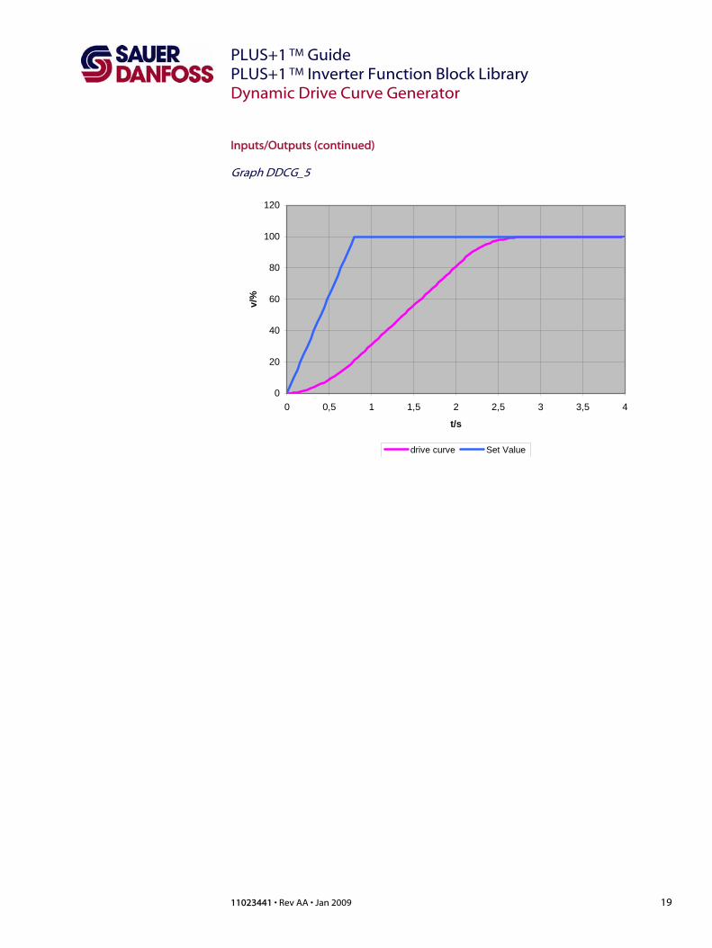
Roundness (U8) Specifies the strange of the roundness (0: no
rounding; 90: max. rounding).
The speed curve is always rounded before
reaching the final value. A rounding at the
beginning of acceleration or deceleration
becomes effective only if the set value changes
slowly. With a slowly change of the set value a
smoothly drive reaction is performed, as
acceleration is increased continuously. In case of a
fast change of the set value an aggressive drive
reaction results, as acceleration achieves it’s
maximum value precipitously. (Graph DDCG_5)
Default: 0 (0…90)
SpdMax_rpm1(U32) Max. speed value of the application.
Default 1500 rpm
(1…200000) [0.1 rpm]

PLUS+1TM Guide PLUS+1 TM Inverter Function Block Library
18 11023441 • Rev AA • Jan 2009
Dynamic Drive Curve Generator
Inputs/Outputs (continued) Graph DDCG_3
Speed curve
0
20
40
60
80
100
120
0 0,5 1 1,5 2 2,5 3 3,5 4
t/s
v/
%
Graph DDCG_4
Speed curve
0
20
40
60
80
100
120
0 0,5 1 1,5 2 2,5 3 3,5 4
t/s
v/
%
PLUS+1 TM Guide PLUS+1 TM Inverter Function Block Library
11023441 • Rev AA • Jan 2009 19
Dynamic Drive Curve Generator
Inputs/Outputs (continued) Graph DDCG_5
0
20
40
60
80
100
120
0 0,5 1 1,5 2 2,5 3 3,5 4
t/s
v/%
drive curve Set Value

PLUS+1TM Guide PLUS+1 TM Inverter Function Block Library
20 11023441 • Rev AA • Jan 2009
Error History
Error History
Function: In the error history memory, the last 8 errors are stored together with a time stamp (HC_h4) and a error counter. If the same error has appeared, consecutively several time, the error will be shown only once, but with the latest time stamp and with an increased error counter. Inputs/Outputs Inputs
Item Description/Range
Clr (BOOL) If the “Clr” input goes active (positive edge), the
complete error history memory, shall be cleared.
HC_h4 (U32) Time stamp [0.001h]
Err (U16) An error is detected, if the “Err” input is unequal
zero.
New error is detected:
“Err” is not equal to the latest error in the memory
and the error level is enabled to store.
- A new entry is made in the error history
memory
- The oldest entry is deleted
An error is detected again:
“Err” is equal to the latest error in the memory and
the error level is enabled to store.
- The time stamp of the latest entry is
updated.
- The error counter is increased.
(0…9999)
ErrStatAct (Bus) The error active- and status active variables are
located in the “ErrStatAct” bus. This variables
indicates, whether the attendant error level is
active.
ErrLev0Act … ErrLev6Act (BOOL) Error level 0…6
is active
StorLev (U8) The “StorLev” input define, whether an error level
can be stored.
StorLev (Bit 0...6) Error level 0…6 is enabled to
store

PLUS+1 TM Guide PLUS+1 TM Inverter Function Block Library
11023441 • Rev AA • Jan 2009 21
Error History
Inputs/Outputs (continued) Output
Item Description/Range
ErrStor (Array [8]; U16) Error storage (Err0….Err7)
HCStor (Array[8]; U32) Time stamp storage (HC0_h4….HC7_h4) [0.001h]
ErrCStor (Array[8]; U16) Counter storage (ErrC0….ErrC7)
The element 0 from the array is the latest element.
PLUS+1TM Guide PLUS+1 TM Inverter Function Block Library
22 11023441 • Rev AA • Jan 2009
Error Status Handler
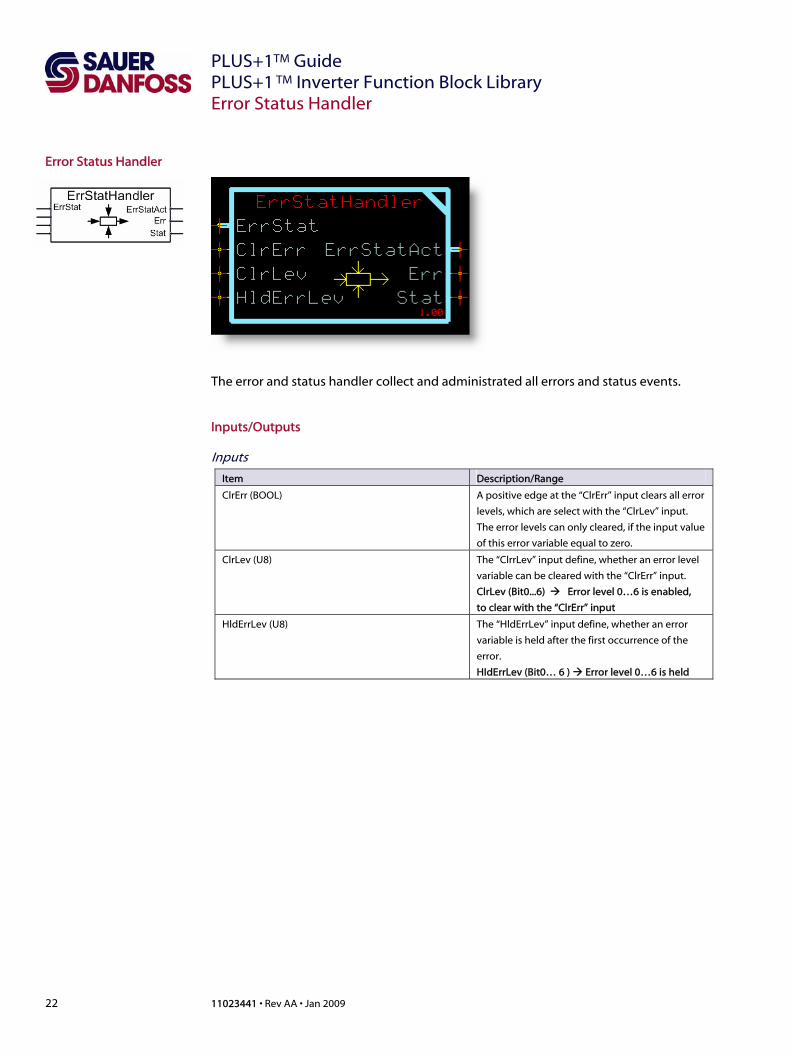
Error Status Handler
The error and status handler collect and administrated all errors and status events. Inputs/Outputs Inputs
Item Description/Range
ClrErr (BOOL) A positive edge at the “ClrErr” input clears all error
levels, which are select with the “ClrLev” input.
The error levels can only cleared, if the input value
of this error variable equal to zero.
ClrLev (U8) The “ClrrLev” input define, whether an error level
variable can be cleared with the “ClrErr” input.
ClrLev (Bit0...6) Error level 0…6 is enabled,
to clear with the “ClrErr” input
HldErrLev (U8) The “HldErrLev” input define, whether an error
variable is held after the first occurrence of the
error.
HIdErrLev (Bit0… 6 ) Error level 0…6 is held

PLUS+1 TM Guide PLUS+1 TM Inverter Function Block Library
11023441 • Rev AA • Jan 2009 23
Error Status Handler
Inputs/Outputs (continued)
Inputs
Item Description/Range
ErrStat (Bus) The error and status variables are located in the
“ErrStat” bus.
Error variable:
ErrLev0 (U16) 0…9999; level 0 (highest priority)
ErrLev1(U16) 0…9999; level 1
ErrLev2(U16) 0…9999; level 2
ErrLev3 (U16) 0…9999; level 3
ErrLev4 (U16) 0…9999 ; level 4
ErrLev5 (U16) 0…9999 ; level 5
ErrLev6 (U16) 0…9999 ; level 6 (lowest priority)
The error variable with the level 0 has the highest
priority and the error variable with the level 6 has
the lowest priority. If the error variables are equal
to zero, no error is triggered. If an error variable is
set to an error number, an error is triggered, with
the attendant error level.
Status variable:
StatLev0 (U16) 0…9999; level 0 (highest priority)
StatLev1 (U16) 0…9999; level 1
StatLev2 (U16) 0…9999; level 2
StatLev3 (U16) 0…9999; level 3 (lowest priority)
The status variable with the level 0 has the
highest priority and the status variable with the
level 3 has the lowest priority. If the status
variables are equal to zero, no status report is
triggered. If a status variable is set to a status
number, a status report is triggered, with the
attendant status level.
PLUS+1TM Guide PLUS+1 TM Inverter Function Block Library
24 11023441 • Rev AA • Jan 2009
Error Status Handler
Inputs/Outputs (continued) Output
Item Description/Range
ErrStatAct (Bus) The error active- and status active variables are
located in the “ErrStatAct” bus. This variables
indicates, whether the attendant level is active.
Error active variables:
ErrLev0Act (BOOL), Error level 0 is active
ErrLev1Act (BOOL), Error level 1 is active
ErrLev2Act (BOOL), Error level 2 is active
ErrLev3Act (BOOL), Error level 3 is active
ErrLev4Act (BOOL), Error level 4 is active
ErrLev5Act (BOOL), Error level 5 is active
ErrLev6Act (BOOL), Error level 6 is active
Status active variables:
StatLev0Act (BOOL), Status level 0 is active
StatLev1Act (BOOL), Status level 1 is active
StatLev2Act (BOOL), Status level 2 is active
StatLev3Act (BOOL), Status level 3 is active
Err (U16) The “Err” output displays the value of the active
error variable, with the highest priority. If the
output is equal to zero, no error is active.
(0…9999)
Stat (U16) The “Stat” output displays the value of the active
status variable , with the highest priority. If the
output is equal to zero, no status report is active.
(0…9999)
The error and status variables can only be connected with the “Value Connect” component.
PLUS+1 TM Guide PLUS+1 TM Inverter Function Block Library
11023441 • Rev AA • Jan 2009 25
Hour Counter
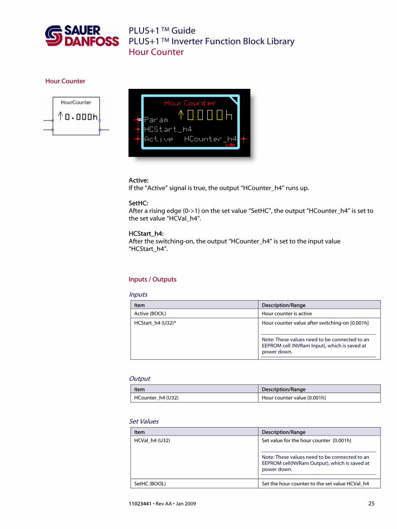
Hour Counter
Active: If the “Active” signal is true, the output “HCounter_h4” runs up. SetHC: After a rising edge (0->1) on the set value “SetHC”, the output “HCounter_h4” is set to the set value “HCVal_h4”. HCStart_h4: After the switching-on, the output “HCounter_h4” is set to the input value “HCStart_h4”. Inputs / Outputs
Inputs
Item Description/Range
Active (BOOL) Hour counter is active
HCStart_h4 (U32)* Hour counter value after switching-on [0.001h]
Note: These values need to be connected to an EEPROM cell (NVRam Input), which is saved at power down.
Output
Item Description/Range
HCounter_h4 (U32) Hour counter value [0.001h]
Set Values
Item Description/Range
HCVal_h4 (U32) Set value for the hour counter [0.001h]
Note: These values need to be connected to an EEPROM cell(NVRam Output), which is saved at power down.
SetHC (BOOL) Set the hour counter to the set value HCVal_h4
PLUS+1TM Guide PLUS+1 TM Inverter Function Block Library
26 11023441 • Rev AA • Jan 2009
Main Contactor
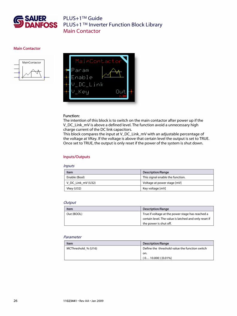
Main Contactor
Function: The intention of this block is to switch on the main contactor after power up if the V_DC_Link_mV is above a defined level. The function avoid a unnecessary high charge current of the DC link capacitors. This block compares the input at V_DC_Link_mV with an adjustable percentage of the voltage at VKey. If the voltage is above that certain level the output is set to TRUE. Once set to TRUE, the output is only reset if the power of the system is shut down. Inputs/Outputs
Inputs
Item Description/Range
Enable (Bool) This signal enable the function.
V_DC_Link_mV (U32) Voltage at power stage [mV]
Vkey (U32) Key voltage [mV]
Output
Item Description/Range
Out (BOOL) True if voltage at the power stage has reached a
certain level. The value is latched and only reset if
the power is shut off.
Parameter
Item Description/Range
MCThreshold_% (U16) Define the threshold value the function switch
on.
( 0… 10.000 ) [0.01%]
PLUS+1 TM Guide PLUS+1 TM Inverter Function Block Library
11023441 • Rev AA • Jan 2009 27
Roll Off
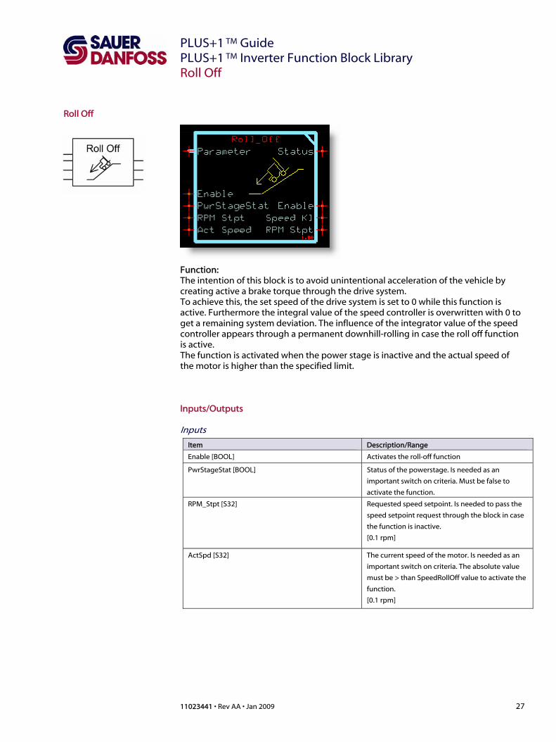
Roll Off
Function: The intention of this block is to avoid unintentional acceleration of the vehicle by creating active a brake torque through the drive system. To achieve this, the set speed of the drive system is set to 0 while this function is active. Furthermore the integral value of the speed controller is overwritten with 0 to get a remaining system deviation. The influence of the integrator value of the speed controller appears through a permanent downhill-rolling in case the roll off function is active. The function is activated when the power stage is inactive and the actual speed of the motor is higher than the specified limit. Inputs/Outputs
Inputs
Item Description/Range
Enable [BOOL] Activates the roll-off function
PwrStageStat [BOOL] Status of the powerstage. Is needed as an
important switch on criteria. Must be false to
activate the function.
RPM_Stpt [S32] Requested speed setpoint. Is needed to pass the
speed setpoint request through the block in case
the function is inactive.
[0.1 rpm]
ActSpd [S32] The current speed of the motor. Is needed as an
important switch on criteria. The absolute value
must be > than SpeedRollOff value to activate the
function.
[0.1 rpm]
PLUS+1TM Guide PLUS+1 TM Inverter Function Block Library
28 11023441 • Rev AA • Jan 2009
Roll Off
Inputs/Outputs (continued)
Output
Item Description/Range
Status [U16] 0x8008 = Invalid setup/calibration
Hysteresis > RollOffSpd
Enable [BOOL] Activates the output enable in case roll off get
active. Activates the output enable in case the roll
off in inactive but the Input Enable = true
SpeedKI [U32] Integral gain of the speed controller.
[0.00001 Nm/rpm/s]
Note: Connect value to the Motor Control
Interface!
RPM_Stpt_Out [S32] Speed setpoint for the motor
[0,1 rpm]

PLUS+1 TM Guide PLUS+1 TM Inverter Function Block Library
11023441 • Rev AA • Jan 2009 29
Roll Off
Inputs/Outputs (continued) Parameter
Item Description/Range
SpeedRollOff [U32] Value at which the function switches to active,
assumed other switch on conditions fulfilled.
[0,1 rpm]
RollOffHysteresis [U16] Defines how far the SpeedRollOff value has to be
under run to switch of the function.
SpeedKI [U32] Integral gain of the speed controller.
[0.00001 Nm/rpm/s]
Note: Delete value on the Motor Control Interface
Default parameter settings generate a “Invalid setup/calibration” status.

PLUS+1TM Guide PLUS+1 TM Inverter Function Block Library
30 11023441 • Rev AA • Jan 2009
Seat Switch
Seat Switch
Function: This function block is a delayed on/off switch. The delay function is active on the negative transition. On a positive transition at the input signal SeatSwitch the output is activated immediately. On a negative transition at the input signal SeatSwitch the output is deactivated after an adjustable delay time. If during the delay time, the input is true again, the output stays true without any interrupts. Inputs/Outputs
Inputs
Item Description/Range
SeatSwitch (BOOL) Signal which will be off delayed
Output
Item Description/Range
Out (BOOL) Off-delayed input signal
Parameter
Item Description/Range
SeatSwDelay_ms (U16) Time after which the output follows the negative
transition on the input.
Default: 1000 ms
(0 … 10.000) [ms]

PLUS+1 TM Guide PLUS+1 TM Inverter Function Block Library
11023441 • Rev AA • Jan 2009 31
Service Counter
Service Counter
Active: If the “Active” signal is true, the output “SHCounter_ha” runs down and stops at zero. SHCZero: If the output “SHCounter_h4” equal to zero, the output “SHCZero” goes to true. SetInterval: After a rising edge (0->1) on the set value “SetInterval”, the output “SHCounter_h4” is set to the parameter value “SHCInterval_h4”. SHCStart_h4: After the switching-on, the output “SHCounter_h4” is set to the input value “SHCStart_h4”.
Inputs/Outputs
Inputs
Item Description/Range
Active(BOOL) Service hour counter is active
SHCStart_h4 (U32) Counter value after switching-on [0.001h]
Note: These values need to be connected to an
EEPROM cell (NVRam Input), which is saved at
power down.
Output
Item Description/Range
SHCZero (BOOL) Service hour counter is invalid
SHCounter_h4 (U32) Service hour counter value [0.001h]
Note: These values need to be connected to an
EEPROM cell (NVRam Output), which is saved at
power down.
Parameter
Item Description/Range
SHCInterval_h4 (U32)
(default value: 500000)
Service interval
Default: 500 h
[0.001h]
SetInterval (BOOL) Set service hour counter to the service interval

PLUS+1TM Guide PLUS+1 TM Inverter Function Block Library
32 11023441 • Rev AA • Jan 2009
Shunting
Shunting
Function: This block allows to set a RPM setpoint for a specified short time. The function is typically used to move a tractor towards the load, by using two buttons at the back of the vehicle. The operator can move the machine fwd or rvs at a low speed by pushing one or the other shunting button. The speed and time period for this function is limited independent how long the buttons are pressed. To activate this function the “EnblStat” (Power stage ) needs to be low and the enable needs to be high.
Inputs/Outputs Inputs
Item Description/Range
EnblStat (BOOL) Status of the PowerStage (disabled/enabled)
Needs to be disabled to allow shunting to work
Enbl (BOOL) This signal enables the function
Fwd (BOOL) Activates shunting in forward direction
Rvs (BOOL) Activates shunting in reverse direction
Warning: These two inputs must not be high at
the same time!
Outputs
Item Description/Range
Active [Bool] This output is TRUE in case of shunting is currently
running.
RPM_Stpt (S32) Value speed set point.
[0,1 rpm]
Parameter
Item Description/Range
ShuntingSpeed (U32) Maximum rpm used when shunting is active
[0,1 rpm]
MaxShuntingTime (U16) Maximum time for which the output is set
[1 ms]

PLUS+1 TM Guide PLUS+1 TM Inverter Function Block Library
11023441 • Rev AA • Jan 2009 33
Solenoid Chopper
Solenoid Chopper
Function: After a rising edge(0->1) on the input signal Activate the output PWM is calculated according to SettlingValue for the time Settling Time_ms and then according to SteadyValue. The PWM_Value is calculated dependant on the actual supply value: If the actual supply value changes the PWM_Value is calculated in order to reach a constant voltage at the load. In order to avoid oscillations at the load voltage the PWM_Value has a hysteresis of 2%. Means the output value only changes if the difference between the result of the calculation and the output value of the previous task is more than 2%. Note: The output value is always 4,99% higher the calculated value. The reason is that the Plus+1 inverters can only handle 10% steps.
Inputs/Outputs Inputs
Item Description/Range
SupplyPWR (U32) Supply power for the according output. Can be
volt or percentage.
Important: This value needs to be of the same
scaling and unit as SETTLING VALUE and STEADY
VALUE!
Activate (BOOL) This signal starts the sequence

PLUS+1TM Guide PLUS+1 TM Inverter Function Block Library
34 11023441 • Rev AA • Jan 2009
Solenoid Chopper
Inputs/Outputs (continued) Output
Item Description/Range
PWM (U16) Value defined by settling resp. steady value
calculated according to the supply power.
(0…10000) [0.01%]
Parameter
Item Description/Range
SettlingTime_ms (U16) Time while settling value is present at the output.
(0… 10.000) [1 ms]
SettlingValue (U32) Output value during settling time
Important: This value needs to be of the same
scaling and unit as SETTLING VALUE and STEADY
VALUE!
SteadyValue (U32) Output value when settling time is over and
Activate is still active
Important: This value needs to be of the same
scaling and unit as SETTLING VALUE and STEADY
VALUE!

PLUS+1 TM Guide PLUS+1 TM Inverter Function Block Library
11023441 • Rev AA • Jan 2009 35
Note

Our Products Open circuit axial piston pumps Gear pumps and motors Fan drive systems Closed circuit axial piston pumps and motors Bent axis motors Hydrostatic transmissions Transit mixer drives Hydrostatic transaxles Electrohydraulics Integrated systems Microcontrollers and software PLUS+1TM GUIDE Displays Joysticks and control handles Sensors Orbital motors Inverters Electrohydraulic power steering Hydraulic power steering Hydraulic integrated circuits (HIC) Cartridge valves Directional spool valves Proportional valves 11023441 • Rev AA • Jan 2009
Sauer-Danfoss Hydraulic Power Systems - Market Leaders Worldwide Sauer-Danfoss is a comprehensive supplier providing complete systems to the global mobile market. Sauer-Danfoss serves markets such as agriculture, construction, road building, material handling, municipal, forestry, turf care, and many others. We offer our customers optimum solutions for their needs and develop new products and systems in close cooperation and partnership with them. Sauer-Danfoss specializes in integrating a full range of system components to provide vehicle designers with the most advanced total system design. Sauer-Danfoss provides comprehensive worldwide service for its products through an extensive network of Global Service Partners strategically located in all parts of the world.
Local address:
Sauer-Danfoss (US) Company Sauer-Danfoss ApS 3500 Annapolis Lane North DK-6430 Nordborg, Denmark Minneapolis, NM 55447, USA Phone: +45 7488 4444 Phone: +1 763 509 2084 Fax: +45 7488 4400 Fax: +1 763 559 0108 Sauer-Danfoss GmbH & Co. OHG Sauer-Danfoss-Daikin LTD Postfach 2460, D-24531 Neumünster Sannomiya Grad Bldg. 8F Krokamp 35, D-24539 Neumünster 2-2-21 Isogami-dori, Chuo-ku Phone: +49 4321 871 0 Kobe, Hyogo 651-0086, Japan Fax: +49 4321 871 284 Phone: +81 78 231 5001 Fax: +81 78 231 5004
www.sauer-danfoss.com