plumbing catalogue - full · mss sp-58 and sp-69 type 10 mss sp-58 and sp-69 type 10 mss sp-58 and...
TRANSCRIPT
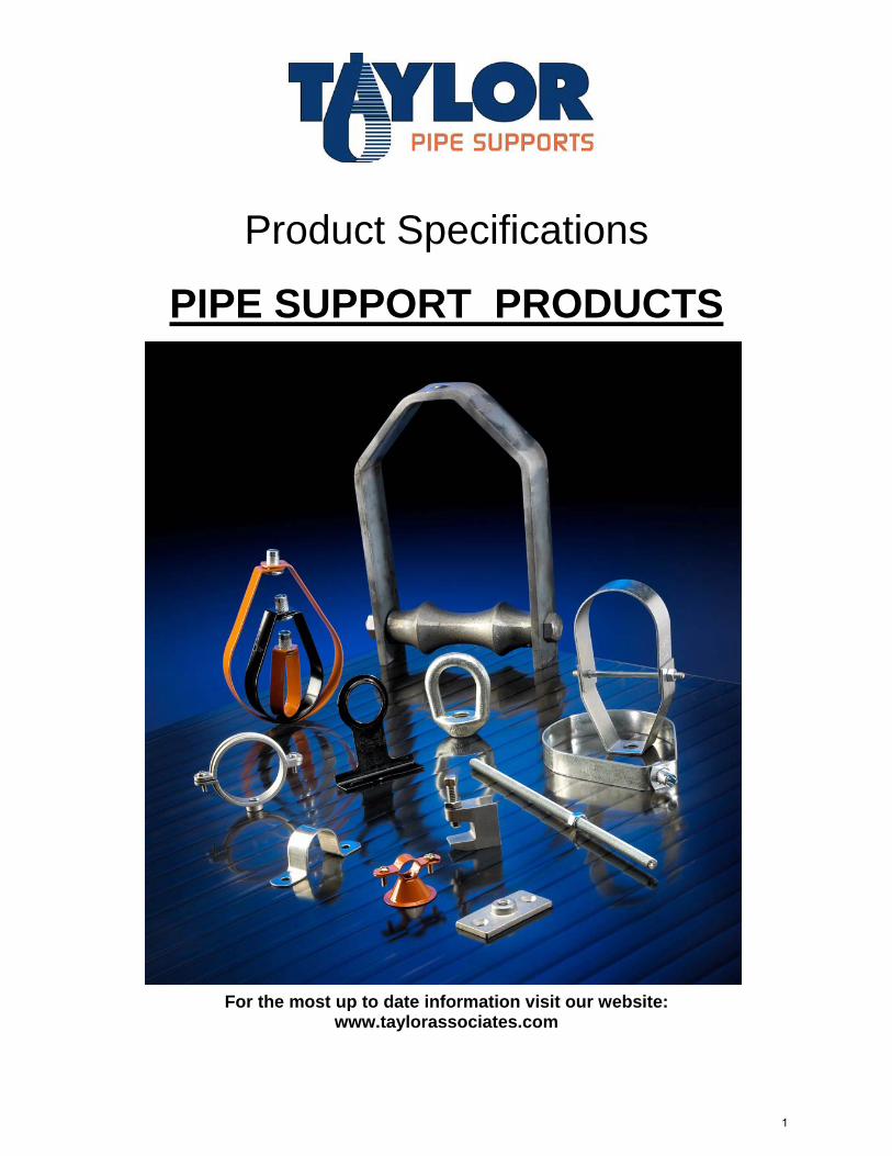
Product Specifications
PIPE SUPPORT PRODUCTS
For the most up to date information visit our website: www.taylorassociates.com
1
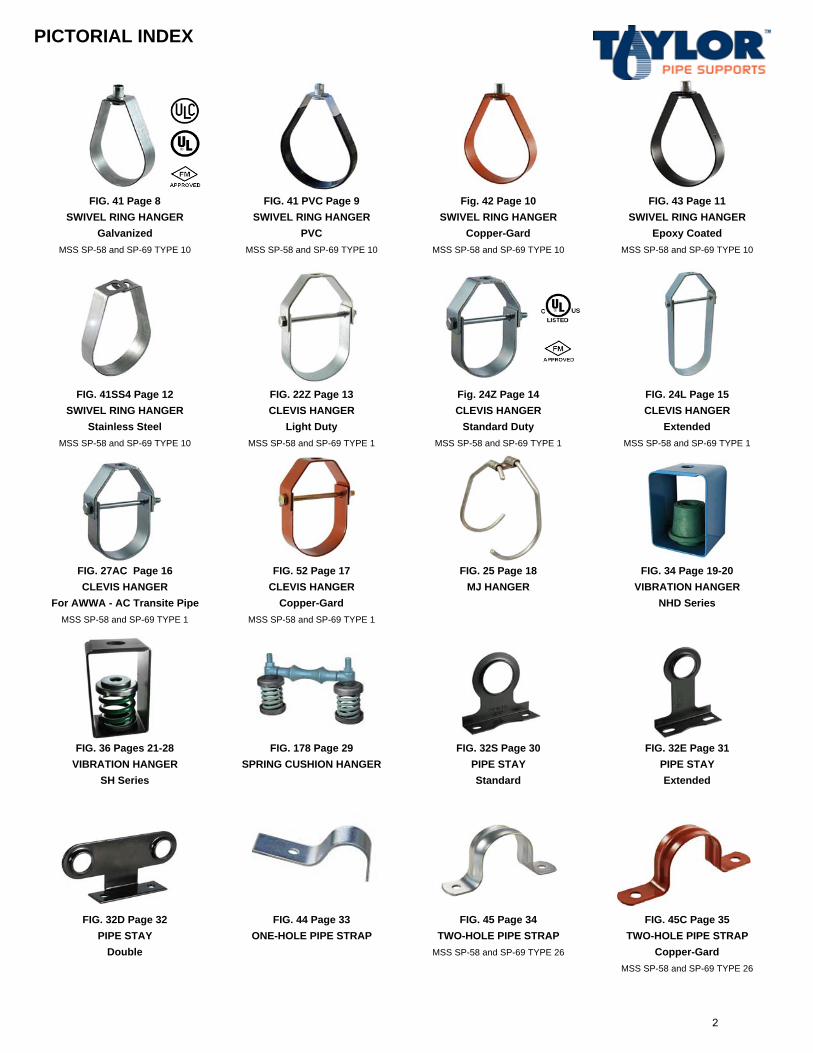
PICTORIAL INDEX
FIG. 41 Page 8 FIG. 41 PVC Page 9 Fig. 42 Page 10 FIG. 43 Page 11SWIVEL RING HANGER SWIVEL RING HANGER SWIVEL RING HANGER SWIVEL RING HANGER
Galvanized PVC Copper-Gard Epoxy CoatedMSS SP-58 and SP-69 TYPE 10 MSS SP-58 and SP-69 TYPE 10 MSS SP-58 and SP-69 TYPE 10 MSS SP-58 and SP-69 TYPE 10
FIG. 41SS4 Page 12 FIG. 22Z Page 13 Fig. 24Z Page 14 FIG. 24L Page 15SWIVEL RING HANGER CLEVIS HANGER CLEVIS HANGER CLEVIS HANGER
Stainless Steel Light Duty Standard Duty ExtendedMSS SP-58 and SP-69 TYPE 10 MSS SP-58 and SP-69 TYPE 1 MSS SP-58 and SP-69 TYPE 1 MSS SP-58 and SP-69 TYPE 1
FIG. 27AC Page 16 FIG. 52 Page 17 FIG. 25 Page 18 FIG. 34 Page 19-20CLEVIS HANGER CLEVIS HANGER MJ HANGER VIBRATION HANGER
For AWWA - AC Transite Pipe Copper-Gard NHD SeriesMSS SP-58 and SP-69 TYPE 1 MSS SP-58 and SP-69 TYPE 1
FIG. 36 Pages 21-28 FIG. 178 Page 29 FIG. 32S Page 30 FIG. 32E Page 31VIBRATION HANGER SPRING CUSHION HANGER PIPE STAY PIPE STAY
SH Series Standard Extended
FIG. 32D Page 32 FIG. 44 Page 33 FIG. 45 Page 34 FIG. 45C Page 35PIPE STAY ONE-HOLE PIPE STRAP TWO-HOLE PIPE STRAP TWO-HOLE PIPE STRAP
Double MSS SP-58 and SP-69 TYPE 26 Copper-GardMSS SP-58 and SP-69 TYPE 26
2
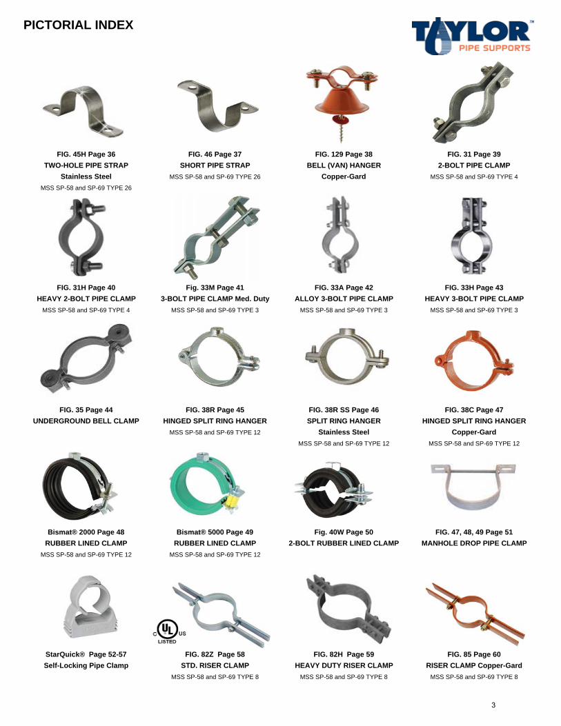
PICTORIAL INDEX
FIG. 45H Page 36 FIG. 46 Page 37 FIG. 129 Page 38 FIG. 31 Page 39TWO-HOLE PIPE STRAP SHORT PIPE STRAP BELL (VAN) HANGER 2-BOLT PIPE CLAMP
Stainless Steel MSS SP-58 and SP-69 TYPE 26 Copper-Gard MSS SP-58 and SP-69 TYPE 4
MSS SP-58 and SP-69 TYPE 26
FIG. 31H Page 40 Fig. 33M Page 41 FIG. 33A Page 42 FIG. 33H Page 43HEAVY 2-BOLT PIPE CLAMP 3-BOLT PIPE CLAMP Med. Duty ALLOY 3-BOLT PIPE CLAMP HEAVY 3-BOLT PIPE CLAMP
MSS SP-58 and SP-69 TYPE 4 MSS SP-58 and SP-69 TYPE 3 MSS SP-58 and SP-69 TYPE 3 MSS SP-58 and SP-69 TYPE 3
FIG. 35 Page 44 FIG. 38R Page 45 FIG. 38R SS Page 46 FIG. 38C Page 47UNDERGROUND BELL CLAMP HINGED SPLIT RING HANGER SPLIT RING HANGER HINGED SPLIT RING HANGER
MSS SP-58 and SP-69 TYPE 12 Stainless Steel Copper-GardMSS SP-58 and SP-69 TYPE 12 MSS SP-58 and SP-69 TYPE 12
Bismat® 2000 Page 48 Bismat® 5000 Page 49 Fig. 40W Page 50 FIG. 47, 48, 49 Page 51RUBBER LINED CLAMP RUBBER LINED CLAMP 2-BOLT RUBBER LINED CLAMP MANHOLE DROP PIPE CLAMP
MSS SP-58 and SP-69 TYPE 12 MSS SP-58 and SP-69 TYPE 12
StarQuick® Page 52-57 FIG. 82Z Page 58 FIG. 82H Page 59 FIG. 85 Page 60Self-Locking Pipe Clamp STD. RISER CLAMP HEAVY DUTY RISER CLAMP RISER CLAMP Copper-Gard
MSS SP-58 and SP-69 TYPE 8 MSS SP-58 and SP-69 TYPE 8 MSS SP-58 and SP-69 TYPE 8
3
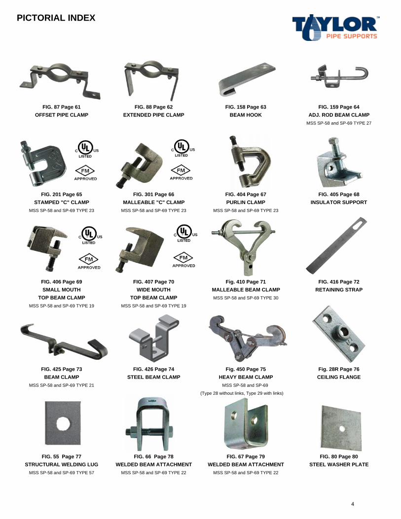
PICTORIAL INDEX
FIG. 87 Page 61 FIG. 88 Page 62 FIG. 158 Page 63 FIG. 159 Page 64OFFSET PIPE CLAMP EXTENDED PIPE CLAMP BEAM HOOK ADJ. ROD BEAM CLAMP
MSS SP-58 and SP-69 TYPE 27
FIG. 201 Page 65 FIG. 301 Page 66 FIG. 404 Page 67 FIG. 405 Page 68STAMPED "C" CLAMP MALLEABLE "C" CLAMP PURLIN CLAMP INSULATOR SUPPORT
MSS SP-58 and SP-69 TYPE 23 MSS SP-58 and SP-69 TYPE 23 MSS SP-58 and SP-69 TYPE 23
FIG. 406 Page 69 FIG. 407 Page 70 Fig. 410 Page 71 FIG. 416 Page 72SMALL MOUTH WIDE MOUTH MALLEABLE BEAM CLAMP RETAINING STRAP
TOP BEAM CLAMP TOP BEAM CLAMP MSS SP-58 and SP-69 TYPE 30
MSS SP-58 and SP-69 TYPE 19 MSS SP-58 and SP-69 TYPE 19
FIG. 425 Page 73 FIG. 426 Page 74 Fig. 450 Page 75 Fig. 28R Page 76BEAM CLAMP STEEL BEAM CLAMP HEAVY BEAM CLAMP CEILING FLANGE
MSS SP-58 and SP-69 TYPE 21 MSS SP-58 and SP-69
(Type 28 without links, Type 29 with links)
FIG. 55 Page 77 FIG. 66 Page 78 FIG. 67 Page 79 FIG. 80 Page 80STRUCTURAL WELDING LUG WELDED BEAM ATTACHMENT WELDED BEAM ATTACHMENT STEEL WASHER PLATE
MSS SP-58 and SP-69 TYPE 57 MSS SP-58 and SP-69 TYPE 22 MSS SP-58 and SP-69 TYPE 22
4
PICTORIAL INDEX
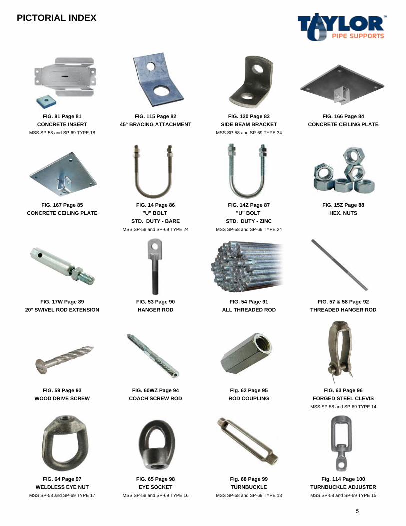
FIG. 81 Page 81 FIG. 115 Page 82 FIG. 120 Page 83 FIG. 166 Page 84CONCRETE INSERT 45° BRACING ATTACHMENT SIDE BEAM BRACKET CONCRETE CEILING PLATE
MSS SP-58 and SP-69 TYPE 18 MSS SP-58 and SP-69 TYPE 34
FIG. 167 Page 85 FIG. 14 Page 86 FIG. 14Z Page 87 FIG. 15Z Page 88CONCRETE CEILING PLATE "U" BOLT "U" BOLT HEX. NUTS
STD. DUTY - BARE STD. DUTY - ZINCMSS SP-58 and SP-69 TYPE 24 MSS SP-58 and SP-69 TYPE 24
FIG. 17W Page 89 FIG. 53 Page 90 FIG. 54 Page 91 FIG. 57 & 58 Page 9220° SWIVEL ROD EXTENSION HANGER ROD ALL THREADED ROD THREADED HANGER ROD
FIG. 59 Page 93 FIG. 60WZ Page 94 Fig. 62 Page 95 FIG. 63 Page 96WOOD DRIVE SCREW COACH SCREW ROD ROD COUPLING FORGED STEEL CLEVIS
MSS SP-58 and SP-69 TYPE 14
FIG. 64 Page 97 FIG. 65 Page 98 Fig. 68 Page 99 Fig. 114 Page 100WELDLESS EYE NUT EYE SOCKET TURNBUCKLE TURNBUCKLE ADJUSTER
MSS SP-58 and SP-69 TYPE 17 MSS SP-58 and SP-69 TYPE 16 MSS SP-58 and SP-69 TYPE 13 MSS SP-58 and SP-69 TYPE 15
5
PICTORIAL INDEX
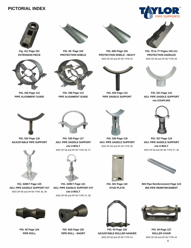
Fig. 411 Page 101 FIG. 69 Page 102 FIG. 69H Page 103 FIG. 70 to 77 Pages 104-111EXTENSION PIECE PROTECTION SHIELD PROTECTION SHIELD - HEAVY PROTECTION SADDLES
MSS SP-58 and SP-69 TYPE 40 MSS SP-58 and SP-69 TYPE 39
FIG. 255 Page 112 FIG. 256 Page 113 FIG. 520 Page 114 FIG. 521 Page 115PIPE ALIGNMENT GUIDE PIPE ALIGNMENT GUIDE PIPE SADDLE SUPPORT ADJ. PIPE SADDLE SUPPORT
c/w COUPLING
FIG. 522 Page 116 FIG. 525 Page 117 FIG. 526 Page 118 FIG. 527 Page 119ADJUSTABLE PIPE SUPPORT ADJ. PIPE SADDLE SUPPORT ADJ. PIPE SADDLE SUPPORT ADJ. PIPE SADDLE SUPPORT
c/w U-BOLT MSS SP-58 and SP-69 TYPE 38 c/w U-BOLTMSS SP-58 and SP-69 TYPE 36, 37 MSS SP-58 and SP-69 TYPE 37, 38
FIG. 528KT Page 120 FIG. 529KT Page 121 FIG. 501 Page 122 BIS Pipe Reinforcement Page 123ADJ. PIPE SADDLE SUPPORT KIT ADJ. PIPE SADDLE SUPPORT KIT STUD PLATE BIS PIPE REINFORCEMENT
MSS SP-58 and SP-69 TYPE 36, 38 c/w U-BOLTMSS SP-58 and SP-69 TYPE 37, 38
FIG. 92 Page 124 FIG. 92S Page 125 FIG. 93 Page 126 FIG. 94 Page 127PIPE ROLL PIPE ROLL - SHORT ADJUSTABLE ROLLER HANGER ROLLER CHAIR
MSS SP-58 and SP-69 TYPE 43 MSS SP-58 and SP-69 TYPE 44 6
PICTORIAL INDEX
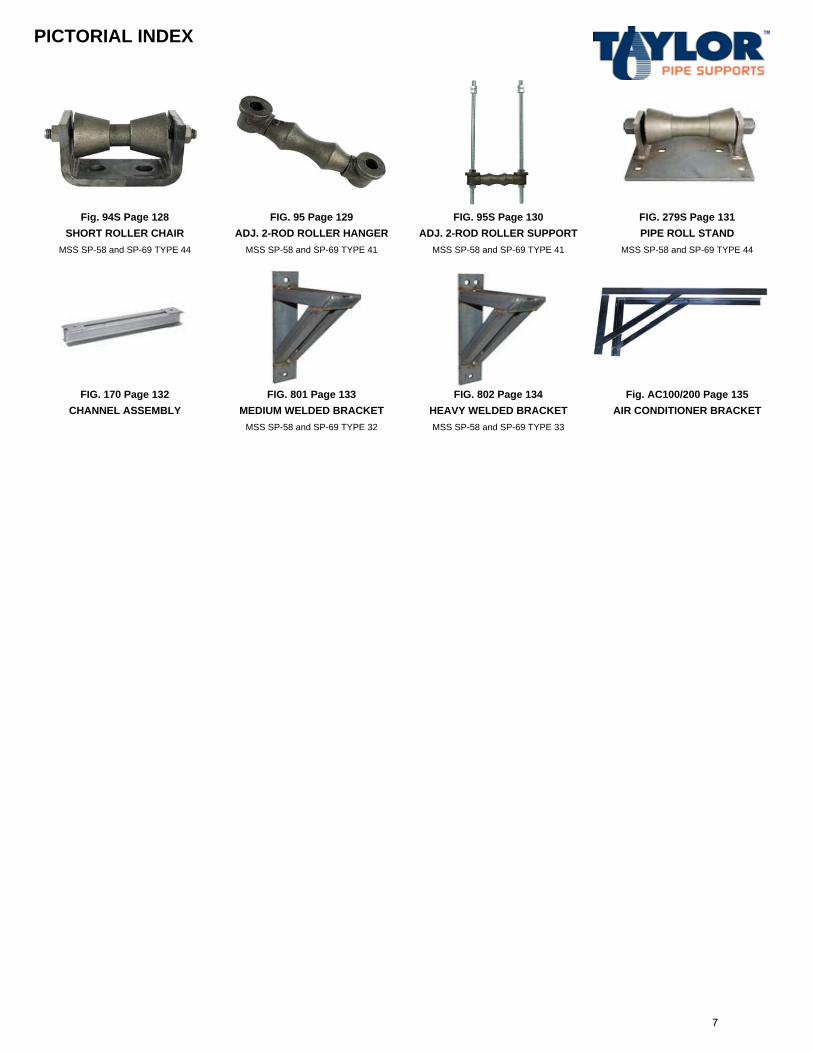
Fig. 94S Page 128 FIG. 95 Page 129 FIG. 95S Page 130 FIG. 279S Page 131SHORT ROLLER CHAIR ADJ. 2-ROD ROLLER HANGER ADJ. 2-ROD ROLLER SUPPORT PIPE ROLL STAND
MSS SP-58 and SP-69 TYPE 44 MSS SP-58 and SP-69 TYPE 41 MSS SP-58 and SP-69 TYPE 41 MSS SP-58 and SP-69 TYPE 44
FIG. 170 Page 132 FIG. 801 Page 133 FIG. 802 Page 134 Fig. AC100/200 Page 135CHANNEL ASSEMBLY MEDIUM WELDED BRACKET HEAVY WELDED BRACKET AIR CONDITIONER BRACKET
MSS SP-58 and SP-69 TYPE 32 MSS SP-58 and SP-69 TYPE 33
7
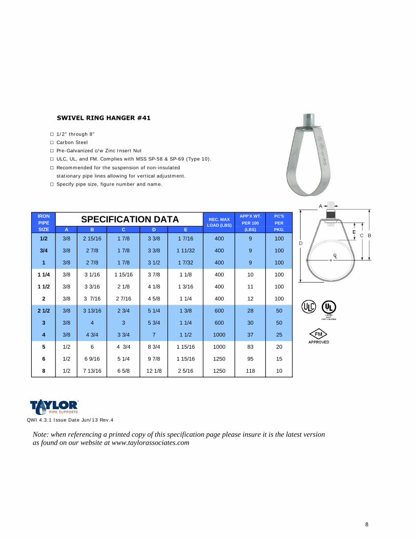
SWIVEL RING HANGER #41
□ 1/2" through 8"
□ Carbon Steel
□ Pre-Galvanized c/w Zinc Insert Nut
□ ULC, UL, and FM. Complies with MSS SP-58 & SP-69 (Type 10).
□ Recommended for the suspension of non-insulated
stationary pipe lines allowing for vertical adjustment.
□ Specify pipe size, figure number and name.
IRON APP'X WT. PC'SPIPE PER 100 PERSIZE A B C D E (LBS) PKG.
QWI 4.3.1 Issue Date Jun/13 Rev.4
Note: when referencing a printed copy of this specification page please insure it is the latest version as found on our website at www.taylorassociates.com
9 100
3/4 3/8 2 7/8 1 7/8 3 3/8 1 11/32 400 9
SPECIFICATION DATA
4001/2 3/8 2 15/16 1 7/8 3 3/8
REC. MAX LOAD (LBS)
1 7/16
100
1 3/8 2 7/8 1 7/8 3 1/2 1 7/32 400 9 100
1 1/4 3/8 3 1/16 1 15/16 3 7/8 1 1/8 400 10 100
1 1/2 3/8 3 3/16 2 1/8 4 1/8 1 3/16 400 11 100
2 3/8 3 7/16 2 7/16 4 5/8 1 1/4 400 12 100
2 1/2 3/8 3 13/16 2 3/4 5 1/4 1 3/8 600 28 50
3 3/8 4 3 5 3/4 1 1/4 600 30 50
4 3/8 4 3/4 3 3/4 7 1 1/2 1000 37 25
5 1/2 6 4 3/4 8 3/4 1 15/16 1000 83 20
95
118 10
15
8 1/2 7 13/16 6 5/8
1250
125012 1/8
6 1/2 5 1/46 9/16
2 5/16
9 7/8 1 15/16
8
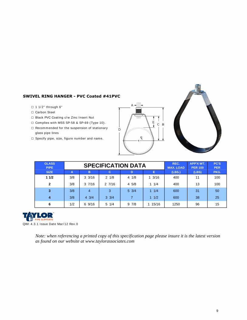
SWIVEL RING HANGER - PVC Coated #41PVC
□ 1 1/2" through 6"
□ Carbon Steel
□ Black PVC Coating c/w Zinc Insert Nut
□ Complies with MSS SP-58 & SP-69 (Type 10).
□ Recommended for the suspension of stationary
glass pipe lines
□ Specify pipe, size, figure number and name.
GLASS REC. APP'X WT. PC'SPIPE MAX. LOAD PER 100 PERSIZE A B C D E (LBS.) (LBS) PKG.
QWI 4.3.1 Issue Date Mar/12 Rev.0
Note: when referencing a printed copy of this specification page please insure it is the latest version as found on our website at www.taylorassociates.com
4001 1/4
6001 1/4
96 159 7/8 1 15/16 12501/2 6 9/16 5 1/46
38 257 1 1/2 6003/8 4 3/4 3 3/4
4 3 50315 3/4
400 11 100
3/8 3 7/16 2 7/16 10013
4 1/83/8 3 3/16 2 1/81 1/2
2
3
4
SPECIFICATION DATA
1 3/16
3/8
4 5/8
9
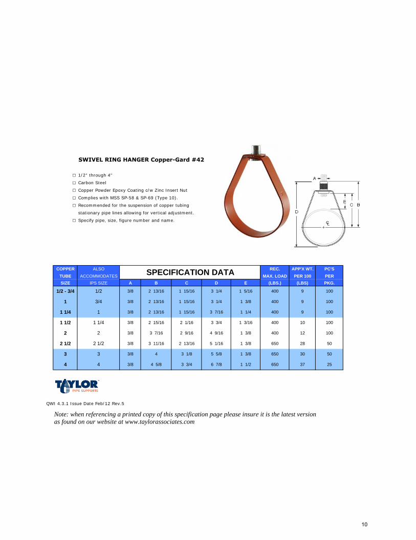
SWIVEL RING HANGER Copper-Gard #42
□ 1/2" through 4"
□ Carbon Steel
□ Copper Powder Epoxy Coating c/w Zinc Insert Nut
□ Complies with MSS SP-58 & SP-69 (Type 10).
□ Recommended for the suspension of copper tubing
stationary pipe lines allowing for vertical adjustment.
□ Specify pipe, size, figure number and name.
COPPER ALSO REC. APP'X WT. PC'STUBE ACCOMMODATES MAX. LOAD PER 100 PERSIZE IPS SIZE A B C D E (LBS.) (LBS) PKG.
QWI 4.3.1 Issue Date Feb/12 Rev.5
Note: when referencing a printed copy of this specification page please insure it is the latest version as found on our website at www.taylorassociates.com
3/4
1
1 1/4
2
SPECIFICATION DATA
1/2 - 3/4 3/8 2 13/161/2 100
1 3/8 2 13/16 1 15/16 3 1/4 1 3/8 400
400 9
9 100
1 1/4 3/8 2 13/16 1 15/16 3 7/16 1 1/4 1009
400
400
1 1/2 3/8 2 15/16 2 1/16 3 3/4 10 100
2 3/8 3 7/16 2 9/16 4 9/16 1 3/8 10012
650
400
2 1/2 3/8 3 11/16 2 13/16 5 1/16 1 3/82 1/2 28 50
3 3/8 4 3 1/8 5 5/8 1 3/8 5030
650
650
4 3/8 4 5/8 3 3/4 6 7/8 1 1/2
3
4 37 25
1 15/16 3 1/4 1 5/16
1 3/16
10
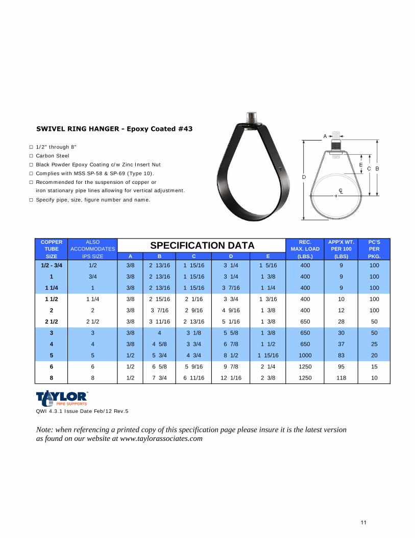
SWIVEL RING HANGER - Epoxy Coated #43
□ 1/2" through 8"
□ Carbon Steel
□ Black Powder Epoxy Coating c/w Zinc Insert Nut
□ Complies with MSS SP-58 & SP-69 (Type 10).
□ Recommended for the suspension of copper or
iron stationary pipe lines allowing for vertical adjustment.
□ Specify pipe, size, figure number and name.
COPPER ALSO REC. APP'X WT. PC'STUBE ACCOMMODATES MAX. LOAD PER 100 PERSIZE IPS SIZE A B C D E (LBS.) (LBS) PKG.
QWI 4.3.1 Issue Date Feb/12 Rev.5
Note: when referencing a printed copy of this specification page please insure it is the latest version as found on our website at www.taylorassociates.com
8
2
2 1/2
3
4
SPECIFICATION DATA
1/2 - 3/4 3/8 2 13/161/2 100
1 3/8 2 13/16 1 15/16 3 1/4 1 3/8 400
400 9
9 100
1 1/4 3/8 2 13/16 1 15/16 1009
3/4
1
1 1/2 3/8 2 15/16 2 1/161 1/4 400
4003 7/16 1 1/4
10 100
2 3/8 3 7/16 2 9/16 10012
3 3/4 1 3/16
2 1/2 3/8 3 11/16 2 13/16
3/8
28 50
3 4 3 1/8 5030
5 1/16 1 3/8
4 3/8 4 5/8 3 3/4 37 25
8 1/2 1 15/16 2083
6 7/8 1 1/2 650
1000
6 1/2 6 5/8 5 9/166
5 1/2 5 3/4 4 3/45
95 15
8 1/2 7 3/4 6 11/16 12 1/16
9 7/8 2 1/4 1250
1250
400
2 3/8
1 3/8
650
650
1 15/16 3 1/4 1 5/16
4 9/16
5 5/8 1 3/8
10118
11
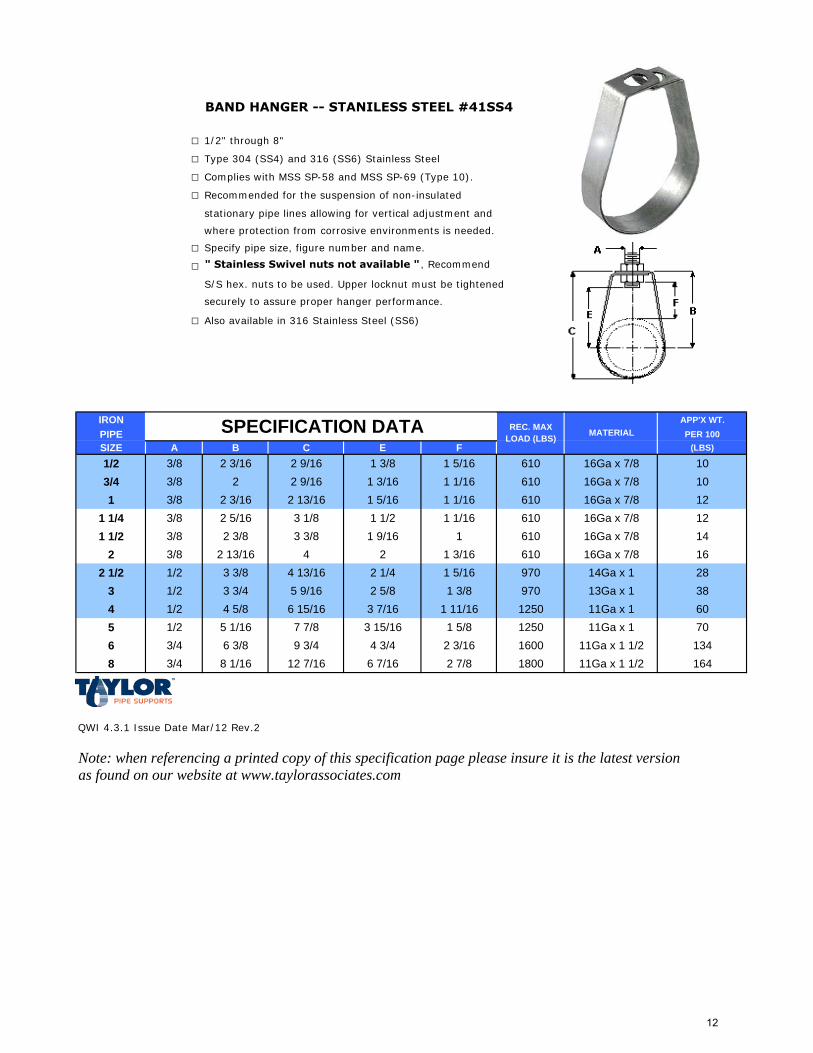
BAND HANGER -- STANILESS STEEL #41SS4
□ 1/2" through 8"
□ Type 304 (SS4) and 316 (SS6) Stainless Steel
□ Complies with MSS SP-58 and MSS SP-69 (Type 10).
□ Recommended for the suspension of non-insulated
stationary pipe lines allowing for vertical adjustment and
where protection from corrosive environments is needed.
□ Specify pipe size, figure number and name.
□ " Stainless Swivel nuts not available " , Recommend
S/S hex. nuts to be used. Upper locknut must be tightened
securely to assure proper hanger performance.
□ Also available in 316 Stainless Steel (SS6)
IRON APP'X WT.PIPE PER 100SIZE A B C E F (LBS)
1/2 3/8 2 3/16 2 9/16 1 3/8 1 5/16 610 16Ga x 7/8 103/4 3/8 2 2 9/16 1 3/16 1 1/16 610 16Ga x 7/8 101 3/8 2 3/16 2 13/16 1 5/16 1 1/16 610 16Ga x 7/8 12
1 1/4 3/8 2 5/16 3 1/8 1 1/2 1 1/16 610 16Ga x 7/8 121 1/2 3/8 2 3/8 3 3/8 1 9/16 1 610 16Ga x 7/8 14
2 3/8 2 13/16 4 2 1 3/16 610 16Ga x 7/8 162 1/2 1/2 3 3/8 4 13/16 2 1/4 1 5/16 970 14Ga x 1 28
3 1/2 3 3/4 5 9/16 2 5/8 1 3/8 970 13Ga x 1 384 1/2 4 5/8 6 15/16 3 7/16 1 11/16 1250 11Ga x 1 605 1/2 5 1/16 7 7/8 3 15/16 1 5/8 1250 11Ga x 1 706 3/4 6 3/8 9 3/4 4 3/4 2 3/16 1600 11Ga x 1 1/2 1348 3/4 8 1/16 12 7/16 6 7/16 2 7/8 1800 11Ga x 1 1/2 164
QWI 4.3.1 Issue Date Mar/12 Rev.2
Note: when referencing a printed copy of this specification page please insure it is the latest version as found on our website at www.taylorassociates.com
SPECIFICATION DATA MATERIALREC. MAX LOAD (LBS)
12
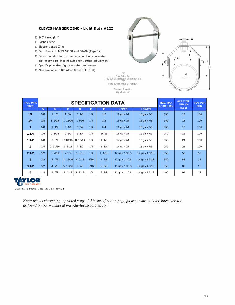
CLEVIS HANGER ZINC - Light Duty #22Z
□ 1/2" through 4"
□ Carbon Steel
□ Electro-plated Zinc
□ Complies with MSS SP-58 and SP-69 (Type 1).
□ Recommended for the suspension of non-insulated
stationary pipe lines allowing for vertical adjustment.
□ Specify pipe size, figure number and name.
□ Also available in Stainless Steel 316 (SS6)'B'
Rod Take-OutPipe center to bottom of hanger rod.
'C'Pipe center to top of hanger.
'D'Bottom of pipe to
top of hanger
A B C D E F UPPER LOWER
1/2 3/8 1 1/8 1 3/4 2 1/8 1/4 1/2 18 ga x 7/8 18 ga x 7/8 250 12 100
3/4 3/8 1 9/16 1 13/16 2 5/16 1/4 1/2 18 ga x 7/8 18 ga x 7/8 250 12 100
1 3/8 1 3/4 2 1/8 2 3/4 1/4 3/4 18 ga x 7/8 18 ga x 7/8 250 12 100
1 1/4 3/8 2 1/32 2 1/2 3 1/4 1/4 15/16 18 ga x 7/8 18 ga x 7/8 250 18 100
1 1/2 3/8 2 1/4 2 13/16 3 13/16 1/4 1 1/8 14 ga x 7/8 16 ga x 7/8 250 24 100
2 3/8 2 11/16 3 5/16 4 1/2 1/4 1 1/4 14 ga x 7/8 16 ga x 7/8 250 26 100
2 1/2 1/2 3 7/16 4 1/2 5 5/16 1/4 2 1/16 12 ga x 1 3/16 14 ga x 1 3/16 350 58 50
3 1/2 3 7/8 4 13/16 6 9/16 5/16 1 7/8 12 ga x 1 3/16 14 ga x 1 3/16 350 66 25
3 1/2 1/2 4 5/8 5 15/16 7 7/8 5/16 2 5/8 11 ga x 1 3/16 14 ga x 1 3/16 350 82 25
4 1/2 4 7/8 6 1/16 8 5/16 3/8 2 3/8 11 ga x 1 3/16 14 ga x 1 3/16 400 94 25
QWI 4.3.1 Issue Date Mar/14 Rev.11
Note: when referencing a printed copy of this specification page please insure it is the latest version as found on our website at www.taylorassociates.com
IRON PIPE SIZE
REC. MAX LOAD (LBS)
APP'X WT. PER 100
(LBS)
PC'S PER PKG.
SPECIFICATION DATA
13
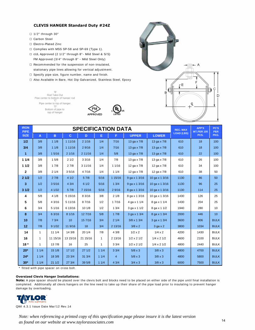
CLEVIS HANGER Standard Duty #24Z
□ 1/2" through 30"
□ Carbon Steel
□ Electro-Plated Zinc
□ Complies with MSS SP-58 and SP-69 (Type 1).
□ cUL Approved (2 1/2" through 8"- Mild Steel & S/S)
FM Approved (3/4" through 8" - Mild Steel Only)
□ Recommended for the suspension of non-insulated,
stationary pipe lines allowing for vertical adjustment.
□ Specify pipe size, figure number, name and finish.
□ Also Available in Bare, Hot Dip Galvanized, Stainless Steel, Epoxy
'B'Rod Take-Out
Pipe center to bottom of hanger rod. 'C'
Pipe center to top of hanger. 'D'
Bottom of pipe to top of hanger
A B C D E F UPPER LOWER
1/2 3/8 1 1/8 1 11/16 2 1/16 1/4 7/16 13 ga x 7/8 13 ga x 7/8 610 18 100
3/4 3/8 1 1/8 1 11/16 2 9/16 1/4 7/16 13 ga x 7/8 13 ga x 7/8 610 18 100
1 3/8 1 5/16 2 1/16 2 11/16 1/4 5/8 13 ga x 7/8 13 ga x 7/8 610 22 100
1 1/4 3/8 1 5/8 2 1/2 3 3/16 1/4 7/8 13 ga x 7/8 13 ga x 7/8 610 26 100
1 1/2 3/8 1 7/8 2 7/8 3 11/16 1/4 1 1/16 12 ga x 7/8 12 ga x 7/8 610 34 100
2 3/8 2 1/4 3 5/16 4 7/16 1/4 1 1/4 12 ga x 7/8 12 ga x 7/8 610 38 50
2 1/2 1/2 2 7/8 4 1/2 5 7/8 5/16 1 15/16 9 ga x 1 3/16 10 ga x 1 3/16 1130 86 50
3 1/2 3 5/16 4 3/4 6 1/2 5/16 1 3/4 9 ga x 1 3/16 10 ga x 1 3/16 1130 96 25
3 1/2 1/2 4 1/32 5 7/8 7 15/16 5/16 2 9/16 8 ga x 1 3/16 10 ga x 1 3/16 1130 114 25
4 5/8 4 1/8 5 15/16 8 3/16 3/8 2 1/8 8 ga x 1 3/16 10 ga x 1 3/16 1430 126 25
5 5/8 4 3/16 5 11/16 8 7/16 1/2 1 7/16 4 ga x 1 1/4 8 ga x 1 1/4 1430 204 25
6 3/4 5 1/16 6 13/16 10 1/8 1/2 1 3/4 3 ga x 1 1/2 8 ga x 1 1/2 1940 280 10
8 3/4 6 3/16 8 1/16 12 7/16 5/8 1 7/8 3 ga x 1 3/4 8 ga x 1 3/4 2000 446 10
10 7/8 7 3/4 10 15 7/16 3/4 2 1/4 3/8 x 1 3/4 3 ga x 1 3/4 3600 806 BULK
12 7/8 9 1/32 11 9/16 18 3/4 2 13/16 3/8 x 2 3 ga x 2 3800 1034 BULK
14 1 11 1/4 14 3/8 20 1/4 7/8 4 3/8 1/2 x 2 1/4 x 2 4200 1430 BULK
16 1 11 15/16 13 15/16 21 15/16 1 2 13/16 1/2 x 2 1/2 1/4 x 2 1/2 4600 2100 BULK
18 * 1 13 7/8 16 25 1 3 3/4 1/2 x 2 1/2 1/4 x 2 1/2 4800 2440 BULK
20* 1 1/4 15 1/8 17 1/2 27 1/2 1 1/4 3 3/4 5/8 x 3 3/8 x 3 4800 4700 BULK
24* 1 1/4 18 3/8 23 3/4 31 3/4 1 1/4 4 5/8 x 3 3/8 x 3 4800 5800 BULK
30* 1 1/4 21 1/2 27 3/4 39 5/8 1 1/4 4 3/4 3/4 x 3 3/8 x 3 6000 7500 BULK
* fitted with pipe spacer on cross bolt.
QWI 4.3.1 Issue Date Mar/12 Rev.14
Note: when referencing a printed copy of this specification page please insure it is the latest version as found on our website at www.taylorassociates.com
IRON PIPE SIZE
APP'X WT.PER 100
PCS.
REC. MAX LOAD (LBS)
Note: A pipe spacer should be placed over the clevis bolt and blocks need to be placed on either side of the pipe until final installation is completed. Additionally all clevis hangers on the line need to take up their share of the pipe load prior to insulating to prevent hanger damage by overloading.
Oversized Clevis Hanger Installations:
PC'S PER PKG.
SPECIFICATION DATA
14
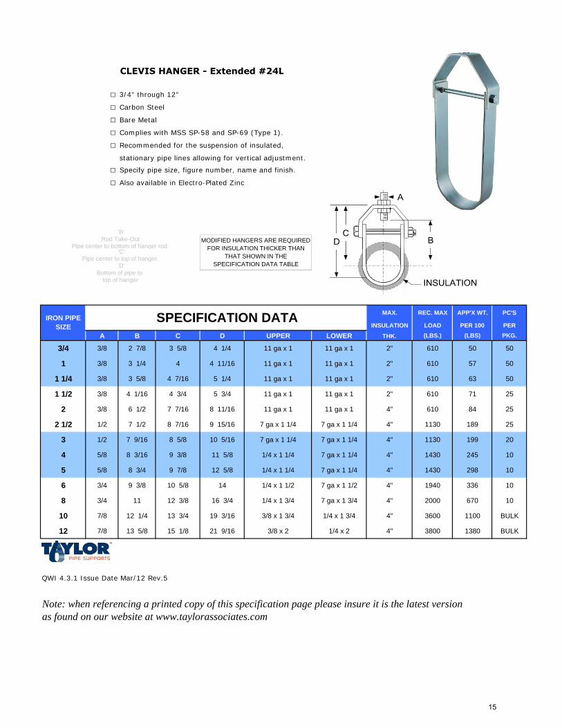
CLEVIS HANGER - Extended #24L
□ 3/4" through 12"
□ Carbon Steel
□ Bare Metal
□ Complies with MSS SP-58 and SP-69 (Type 1).
□ Recommended for the suspension of insulated,
stationary pipe lines allowing for vertical adjustment.
□ Specify pipe size, figure number, name and finish.
□ Also available in Electro-Plated Zinc
MAX. REC. MAX APP'X WT. PC'S
INSULATION LOAD PER 100 PER
A B C D UPPER LOWER THK. (LBS.) (LBS) PKG.
3/4 3/8 2 7/8 3 5/8 4 1/4 11 ga x 1 11 ga x 1 2" 610 50 50
1 3/8 3 1/4 4 4 11/16 11 ga x 1 11 ga x 1 2" 610 57 50
1 1/4 3/8 3 5/8 4 7/16 5 1/4 11 ga x 1 11 ga x 1 2" 610 63 50
1 1/2 3/8 4 1/16 4 3/4 5 3/4 11 ga x 1 11 ga x 1 2" 610 71 25
2 3/8 6 1/2 7 7/16 8 11/16 11 ga x 1 11 ga x 1 4" 610 84 25
2 1/2 1/2 7 1/2 8 7/16 9 15/16 7 ga x 1 1/4 7 ga x 1 1/4 4" 1130 189 25
3 1/2 7 9/16 8 5/8 10 5/16 7 ga x 1 1/4 7 ga x 1 1/4 4" 1130 199 20
4 5/8 8 3/16 9 3/8 11 5/8 1/4 x 1 1/4 7 ga x 1 1/4 4" 1430 245 10
5 5/8 8 3/4 9 7/8 12 5/8 1/4 x 1 1/4 7 ga x 1 1/4 4" 1430 298 10
6 3/4 9 3/8 10 5/8 14 1/4 x 1 1/2 7 ga x 1 1/2 4" 1940 336 10
8 3/4 11 12 3/8 16 3/4 1/4 x 1 3/4 7 ga x 1 3/4 4" 2000 670 10
10 7/8 12 1/4 13 3/4 19 3/16 3/8 x 1 3/4 1/4 x 1 3/4 4" 3600 1100 BULK
12 7/8 13 5/8 15 1/8 21 9/16 3/8 x 2 1/4 x 2 4" 3800 1380 BULK
QWI 4.3.1 Issue Date Mar/12 Rev.5
Note: when referencing a printed copy of this specification page please insure it is the latest version as found on our website at www.taylorassociates.com
'B'Rod Take-Out
Pipe center to bottom of hanger rod. 'C'
'D'Bottom of pipe to
MODIFIED HANGERS ARE REQUIRED FOR INSULATION THICKER THAN
THAT SHOWN IN THE SPECIFICATION DATA TABLE
IRON PIPE SIZE
SPECIFICATION DATA
top of hanger
Pipe center to top of hanger.
15
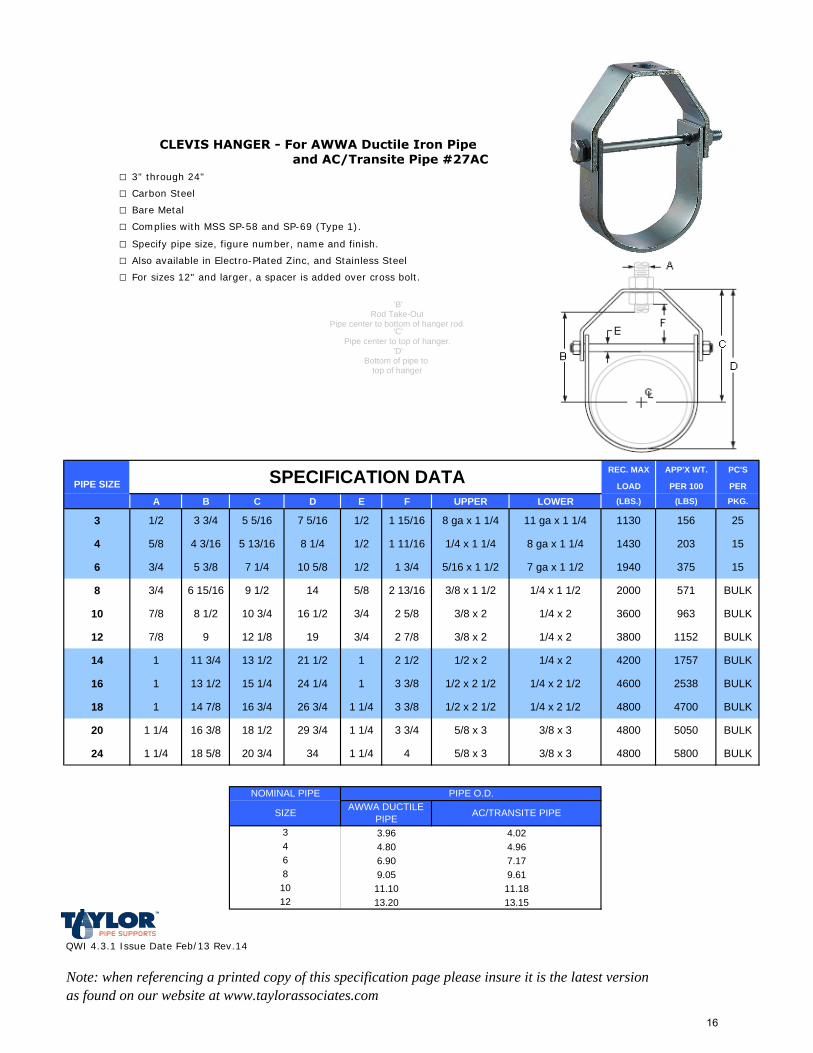
□ 3" through 24"
□ Carbon Steel
□ Bare Metal
□ Complies with MSS SP-58 and SP-69 (Type 1).
□ Specify pipe size, figure number, name and finish.
□ Also available in Electro-Plated Zinc, and Stainless Steel
□ For sizes 12" and larger, a spacer is added over cross bolt.
REC. MAX APP'X WT. PC'S
LOAD PER 100 PER
A B C D E F UPPER LOWER (LBS.) (LBS) PKG.
3 1/2 3 3/4 5 5/16 7 5/16 1/2 1 15/16 8 ga x 1 1/4 11 ga x 1 1/4 1130 156 25
4 5/8 4 3/16 5 13/16 8 1/4 1/2 1 11/16 1/4 x 1 1/4 8 ga x 1 1/4 1430 203 15
6 3/4 5 3/8 7 1/4 10 5/8 1/2 1 3/4 5/16 x 1 1/2 7 ga x 1 1/2 1940 375 15
8 3/4 6 15/16 9 1/2 14 5/8 2 13/16 3/8 x 1 1/2 1/4 x 1 1/2 2000 571 BULK
10 7/8 8 1/2 10 3/4 16 1/2 3/4 2 5/8 3/8 x 2 1/4 x 2 3600 963 BULK
12 7/8 9 12 1/8 19 3/4 2 7/8 3/8 x 2 1/4 x 2 3800 1152 BULK
14 1 11 3/4 13 1/2 21 1/2 1 2 1/2 1/2 x 2 1/4 x 2 4200 1757 BULK
16 1 13 1/2 15 1/4 24 1/4 1 3 3/8 1/2 x 2 1/2 1/4 x 2 1/2 4600 2538 BULK
18 1 14 7/8 16 3/4 26 3/4 1 1/4 3 3/8 1/2 x 2 1/2 1/4 x 2 1/2 4800 4700 BULK
20 1 1/4 16 3/8 18 1/2 29 3/4 1 1/4 3 3/4 5/8 x 3 3/8 x 3 4800 5050 BULK
24 1 1/4 18 5/8 20 3/4 34 1 1/4 4 5/8 x 3 3/8 x 3 4800 5800 BULK
QWI 4.3.1 Issue Date Feb/13 Rev.14
Note: when referencing a printed copy of this specification page please insure it is the latest version as found on our website at www.taylorassociates.com
CLEVIS HANGER - For AWWA Ductile Iron Pipe and AC/Transite Pipe #27AC
13.20 13.15
9.05 9.6111.10 11.18
6.90 7.17
3.96 4.024.80 4.96
1012
3468
Bottom of pipe to
SPECIFICATION DATA
SIZE
NOMINAL PIPEAWWA DUCTILE
PIPE AC/TRANSITE PIPE
PIPE O.D.
PIPE SIZE
top of hanger
Pipe center to top of hanger.'D'
'B'Rod Take-Out
Pipe center to bottom of hanger rod.'C'
16
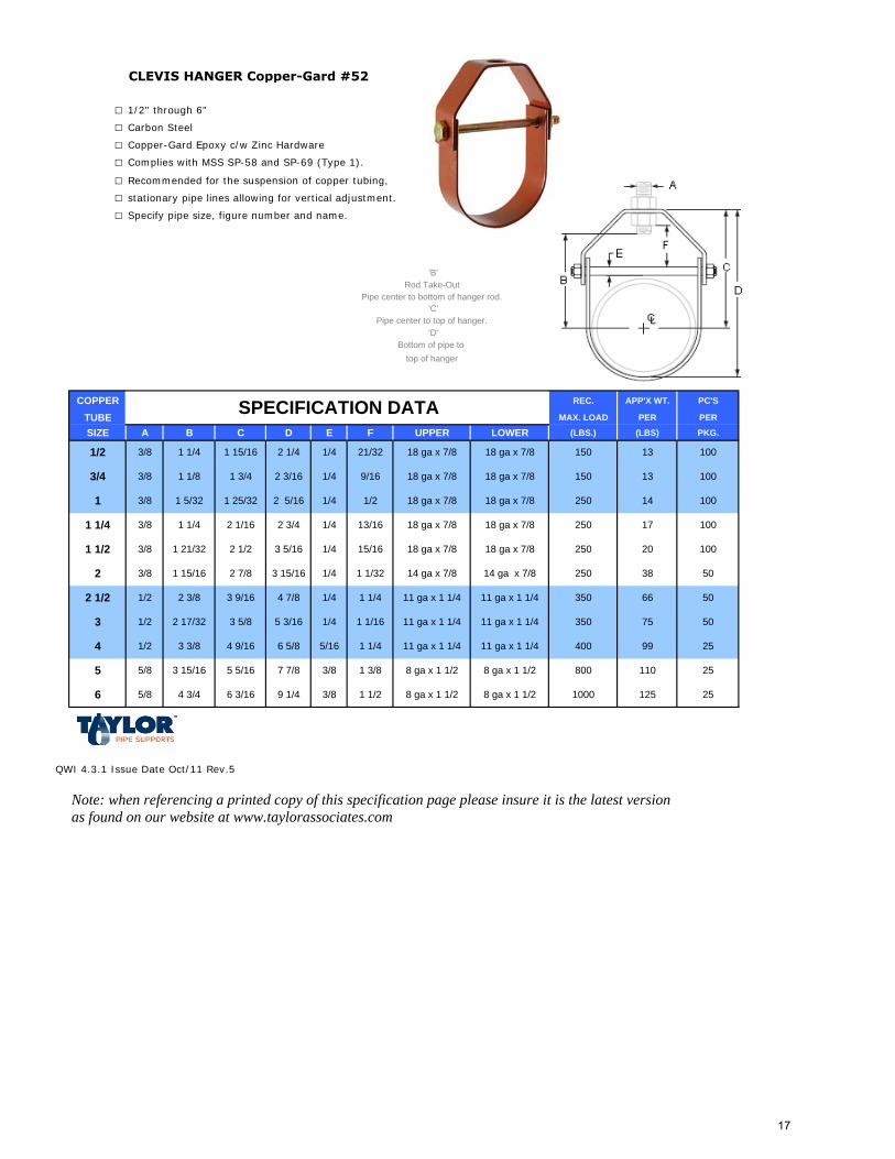
CLEVIS HANGER Copper-Gard #52
□ 1/2" through 6"
□ Carbon Steel
□ Copper-Gard Epoxy c/w Zinc Hardware
□ Complies with MSS SP-58 and SP-69 (Type 1).
□ Recommended for the suspension of copper tubing,
□ stationary pipe lines allowing for vertical adjustment.
□ Specify pipe size, figure number and name.
'B'Rod Take-Out
Pipe center to bottom of hanger rod.'C'
Pipe center to top of hanger.'D'
Bottom of pipe to top of hanger
COPPER REC. APP'X WT. PC'S
TUBE MAX. LOAD PER PER
SIZE A B C D E F UPPER LOWER (LBS.) (LBS) PKG.
QWI 4.3.1 Issue Date Oct/11 Rev.5
Note: when referencing a printed copy of this specification page please insure it is the latest version as found on our website at www.taylorassociates.com
5 5/8
8 ga x 1 1/2 10008 ga x 1 1/2
3 15/16 5 5/16
125 25
25
6 5/8 4 3/4 6 3/16 9 1/4 3/8 1 1/2
1 25/32
1107 7/8 3/8 1 3/8 8 ga x 1 1/2 8 ga x 1 1/2 800
18 ga x 7/81/4
1 1/2 3/8 1 21/32
1/2 3/8 1 1/4
1 3/8 1 5/32
1 1/4
SPECIFICATION DATA
2 1/4 1/4 21/32 18 ga x 7/8 18 ga x 7/8 100
3/4 3/8 1 1/8 1 3/4 2 3/16 1/4 9/16
1 15/16
18 ga x 7/8 150 13
150 13
100
2 5/16 1/4 1/2 18 ga x 7/8 18 ga x 7/8 250 14 100
18 ga x 7/8
3/8 1 1/4 2 1/16 2 3/4 13/16 18 ga x 7/8 250 17 100
2 1/2 3 5/16 1/4 15/16 18 ga x 7/8 18 ga x 7/8 250 20 100
2 3/8 1 15/16 2 7/8 14 ga x 7/8 250 383 15/16 1/4 1 1/32 5014 ga x 7/8
2 1/2 1/2 2 3/8 3 9/16 4 7/8 1/4 1 1/4 11 ga x 1 1/4 11 ga x 1 1/4 350
35011 ga x 1 1/43 1/2 2 17/32 3 5/8 75 50
5066
99 254 1/2 3 3/8 4 9/16 6 5/8 5/16 1 1/4 11 ga x 1 1/4 40011 ga x 1 1/4
5 3/16 1/4 1 1/16 11 ga x 1 1/4
17
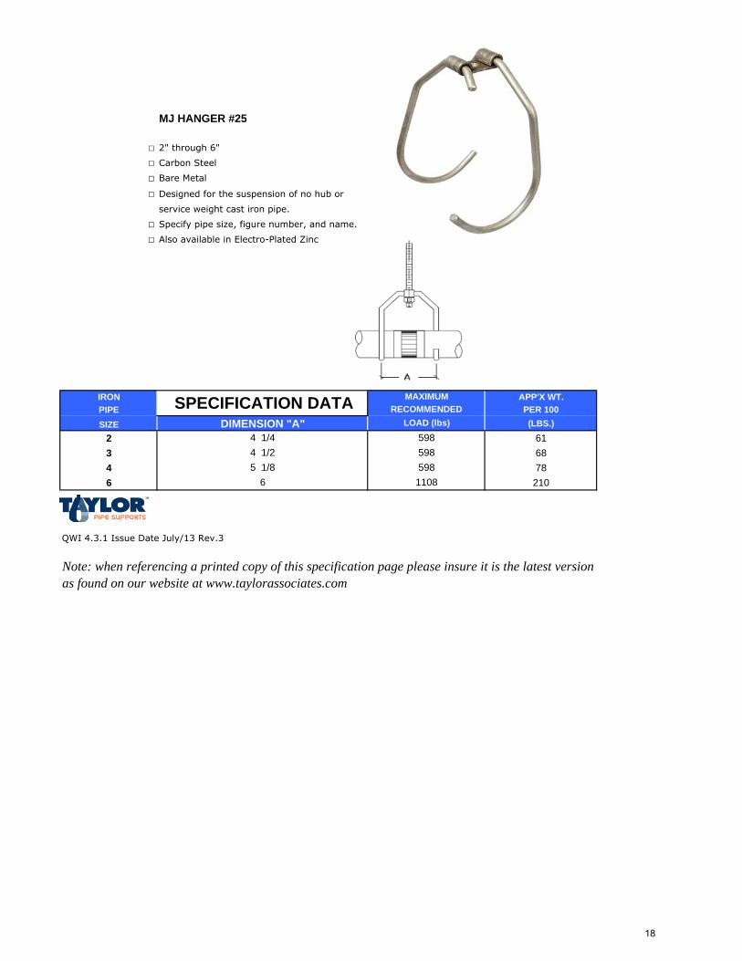
MJ HANGER #25
□ 2" through 6"
□ Carbon Steel
□ Bare Metal
□ Designed for the suspension of no hub or
service weight cast iron pipe.
□ Specify pipe size, figure number, and name.
□ Also available in Electro-Plated Zinc
IRON APP'X WT.PIPE PER 100SIZE (LBS.)
2 613 684 786 210
QWI 4.3.1 Issue Date July/13 Rev.3
Note: when referencing a printed copy of this specification page please insure it is the latest version as found on our website at www.taylorassociates.com
5986 1108
5 1/8
SPECIFICATION DATADIMENSION "A"
4 1/44 1/2
MAXIMUMRECOMMENDED
LOAD (lbs)
598598
18
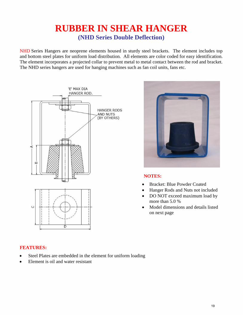
RUBBER IN SHEAR HANGER (NHD Series Double Deflection)
NHD Series Hangers are neoprene elements housed in sturdy steel brackets. The element includes top
and bottom steel plates for uniform load distribution. All elements are color coded for easy identification.
The element incorporates a projected collar to prevent metal to metal contact between the rod and bracket.
The NHD series hangers are used for hanging machines such as fan coil units, fans etc.
NOTES:
Bracket: Blue Powder Coated
Hanger Rods and Nuts not included
DO NOT exceed maximum load by
more than 5.0 %
Model dimensions and details listed
on next page
FEATURES:
Steel Plates are embedded in the element for uniform loading
Element is oil and water resistant
19
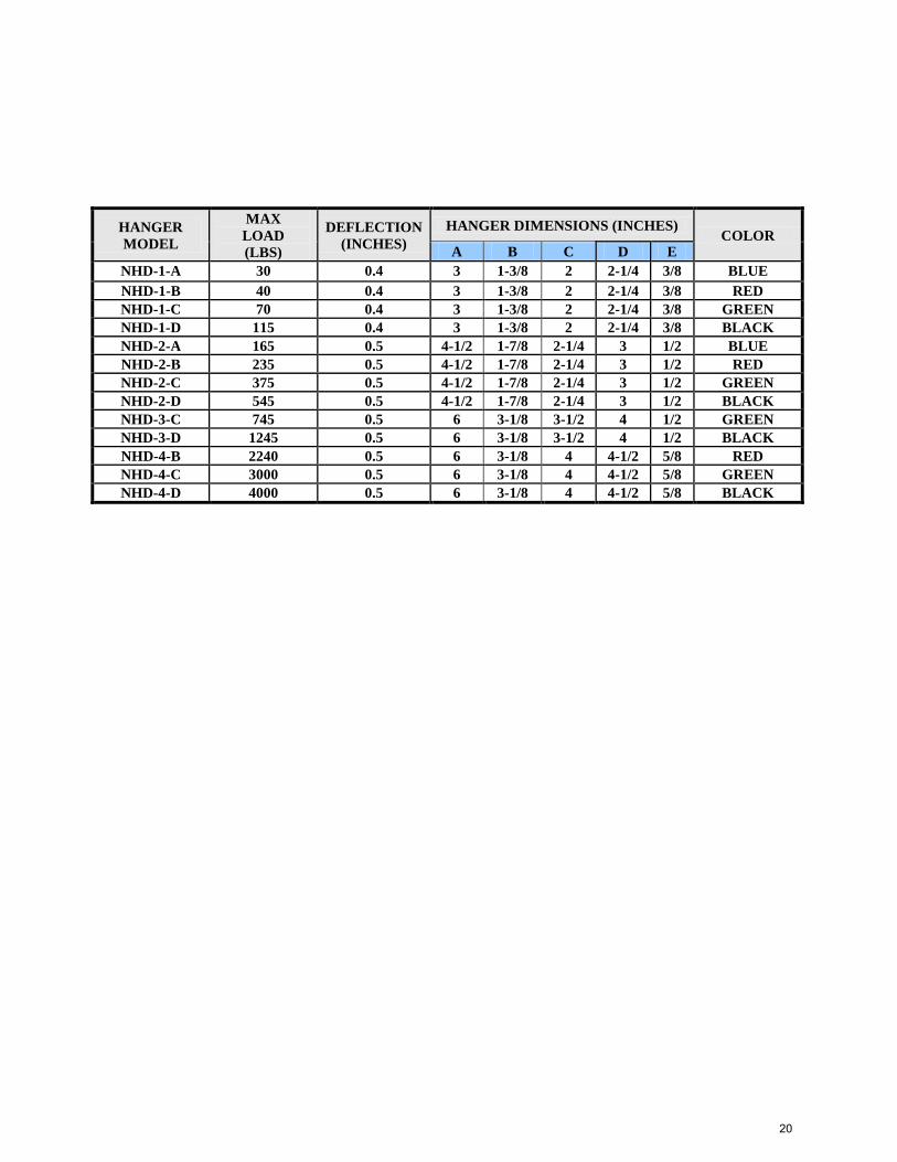
HANGER
MODEL
MAX
LOAD
(LBS)
DEFLECTION
(INCHES)
HANGER DIMENSIONS (INCHES) COLOR
A B C D E
NHD-1-A 30 0.4 3 1-3/8 2 2-1/4 3/8 BLUE
NHD-1-B 40 0.4 3 1-3/8 2 2-1/4 3/8 RED NHD-1-C 70 0.4 3 1-3/8 2 2-1/4 3/8 GREEN NHD-1-D 115 0.4 3 1-3/8 2 2-1/4 3/8 BLACK NHD-2-A 165 0.5 4-1/2 1-7/8 2-1/4 3 1/2 BLUE NHD-2-B 235 0.5 4-1/2 1-7/8 2-1/4 3 1/2 RED NHD-2-C 375 0.5 4-1/2 1-7/8 2-1/4 3 1/2 GREEN NHD-2-D 545 0.5 4-1/2 1-7/8 2-1/4 3 1/2 BLACK NHD-3-C 745 0.5 6 3-1/8 3-1/2 4 1/2 GREEN NHD-3-D 1245 0.5 6 3-1/8 3-1/2 4 1/2 BLACK NHD-4-B 2240 0.5 6 3-1/8 4 4-1/2 5/8 RED NHD-4-C 3000 0.5 6 3-1/8 4 4-1/2 5/8 GREEN NHD-4-D 4000 0.5 6 3-1/8 4 4-1/2 5/8 BLACK
20
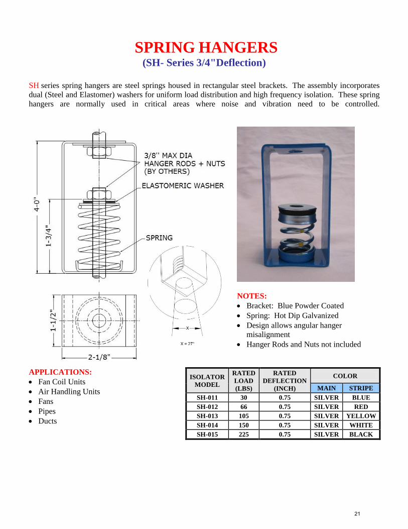
SPRING HANGERS (SH- Series 3/4"Deflection)
SH series spring hangers are steel springs housed in rectangular steel brackets. The assembly incorporates
dual (Steel and Elastomer) washers for uniform load distribution and high frequency isolation. These spring
hangers are normally used in critical areas where noise and vibration need to be controlled.
NOTES:
Bracket: Blue Powder Coated
Spring: Hot Dip Galvanized
Design allows angular hanger
misalignment
Hanger Rods and Nuts not included
APPLICATIONS:
Fan Coil Units
Air Handling Units
Fans
Pipes
Ducts
ISOLATOR
MODEL
RATED
LOAD
(LBS)
RATED
DEFLECTION
(INCH)
COLOR
MAIN STRIPE
SH-011 30 0.75 SILVER BLUE
SH-012 66 0.75 SILVER RED
SH-013 105 0.75 SILVER YELLOW
SH-014 150 0.75 SILVER WHITE
SH-015 225 0.75 SILVER BLACK
21
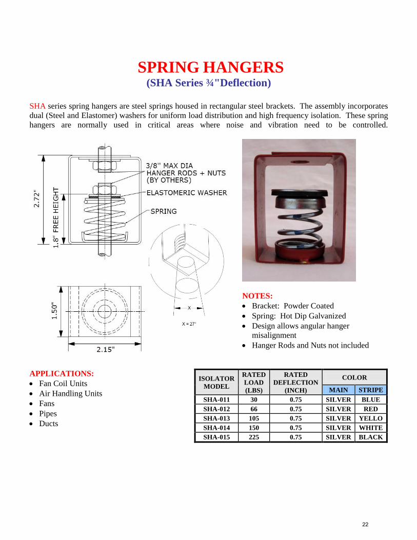
SPRING HANGERS (SHA Series ¾"Deflection)
SHA series spring hangers are steel springs housed in rectangular steel brackets. The assembly incorporates
dual (Steel and Elastomer) washers for uniform load distribution and high frequency isolation. These spring
hangers are normally used in critical areas where noise and vibration need to be controlled.
NOTES:
Bracket: Powder Coated
Spring: Hot Dip Galvanized
Design allows angular hanger
misalignment
Hanger Rods and Nuts not included
APPLICATIONS:
Fan Coil Units
Air Handling Units
Fans
Pipes
Ducts
ISOLATOR
MODEL
RATED
LOAD
(LBS)
RATED
DEFLECTION
(INCH)
COLOR
MAIN STRIPE
SHA-011 30 0.75 SILVER BLUE
SHA-012 66 0.75 SILVER RED
SHA-013 105 0.75 SILVER YELLO
SHA-014 150 0.75 SILVER WHITE
SHA-015 225 0.75 SILVER BLACK
22
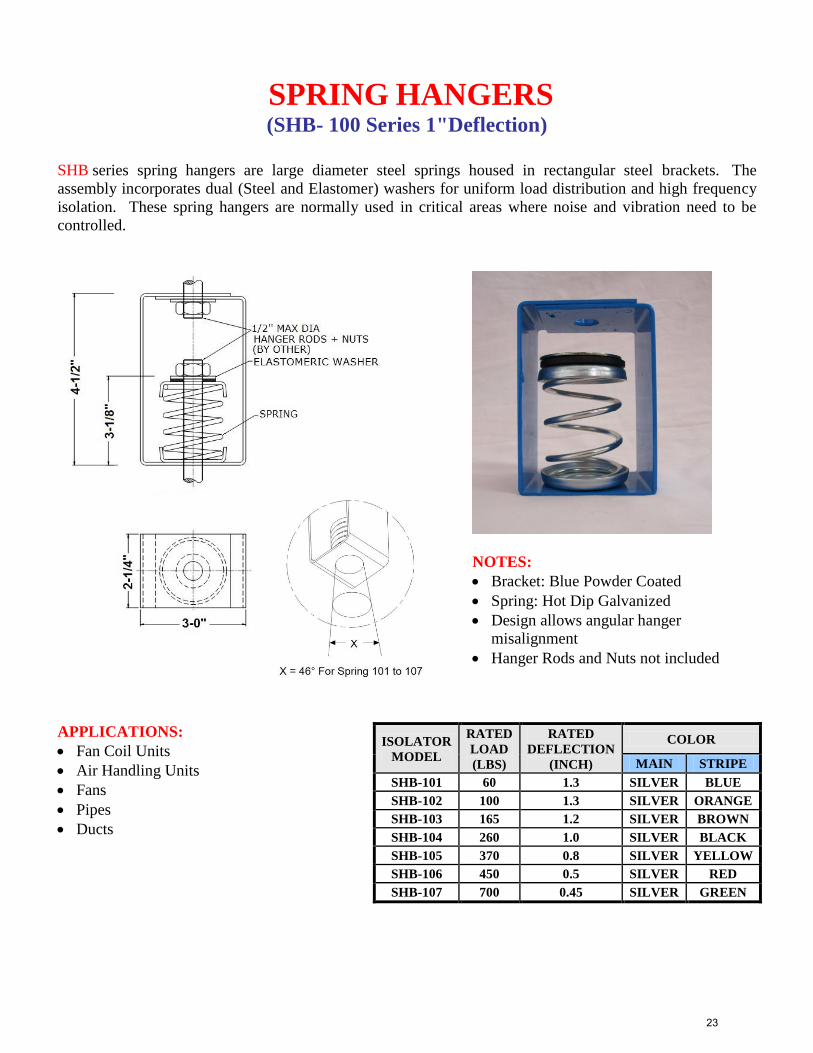
SPRING HANGERS (SHB- 100 Series 1"Deflection)
SHB series spring hangers are large diameter steel springs housed in rectangular steel brackets. The
assembly incorporates dual (Steel and Elastomer) washers for uniform load distribution and high frequency
isolation. These spring hangers are normally used in critical areas where noise and vibration need to be
controlled.
NOTES:
Bracket: Blue Powder Coated
Spring: Hot Dip Galvanized
Design allows angular hanger
misalignment
Hanger Rods and Nuts not included
APPLICATIONS:
Fan Coil Units
Air Handling Units
Fans
Pipes
Ducts
ISOLATOR
MODEL
RATED
LOAD
(LBS)
RATED
DEFLECTION
(INCH)
COLOR
MAIN STRIPE
SHB-101 60 1.3 SILVER BLUE
SHB-102 100 1.3 SILVER ORANGE
SHB-103 165 1.2 SILVER BROWN
SHB-104 260 1.0 SILVER BLACK
SHB-105 370 0.8 SILVER YELLOW
SHB-106 450 0.5 SILVER RED
SHB-107 700 0.45 SILVER GREEN
23
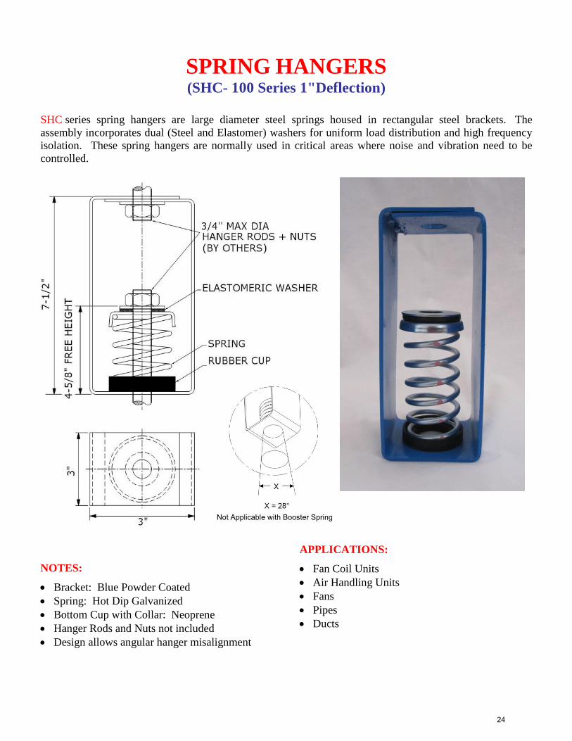
SPRING HANGERS (SHC- 100 Series 1"Deflection)
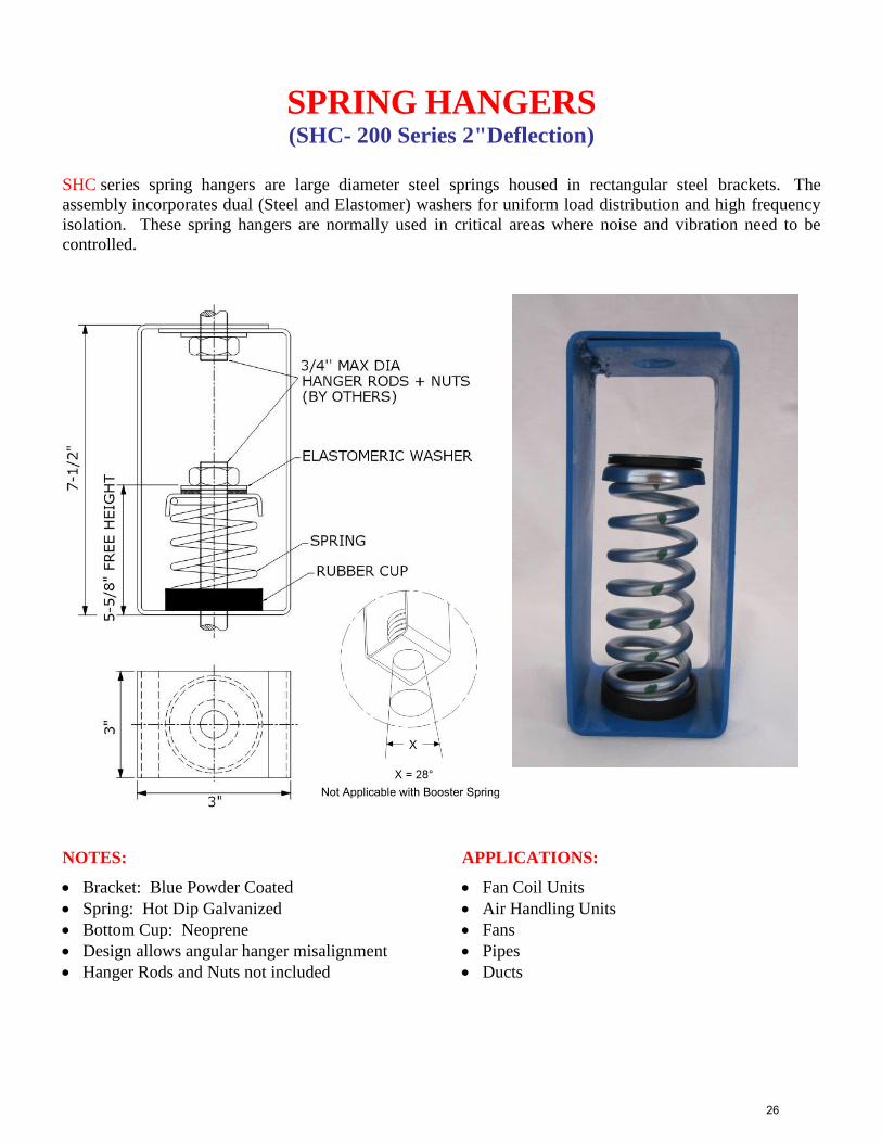
SHC series spring hangers are large diameter steel springs housed in rectangular steel brackets. The
assembly incorporates dual (Steel and Elastomer) washers for uniform load distribution and high frequency
isolation. These spring hangers are normally used in critical areas where noise and vibration need to be
controlled.
NOTES:
Bracket: Blue Powder Coated
Spring: Hot Dip Galvanized
Bottom Cup with Collar: Neoprene
Hanger Rods and Nuts not included
Design allows angular hanger misalignment
APPLICATIONS:
Fan Coil Units
Air Handling Units
Fans
Pipes
Ducts
24
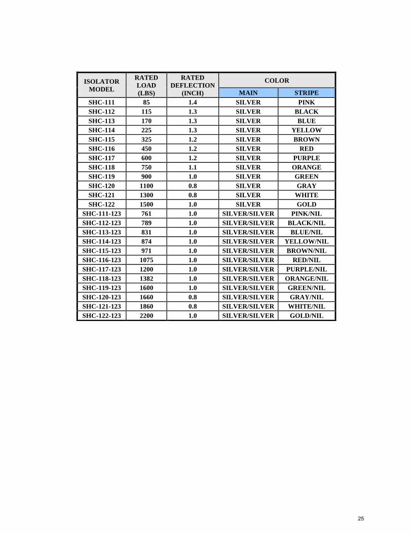
ISOLATOR
MODEL
RATED
LOAD
(LBS)
RATED
DEFLECTION
(INCH)
COLOR
MAIN STRIPE
SHC-111 85 1.4 SILVER PINK
SHC-112 115 1.3 SILVER BLACK
SHC-113 170 1.3 SILVER BLUE
SHC-114 225 1.3 SILVER YELLOW
SHC-115 325 1.2 SILVER BROWN
SHC-116 450 1.2 SILVER RED
SHC-117 600 1.2 SILVER PURPLE
SHC-118 750 1.1 SILVER ORANGE
SHC-119 900 1.0 SILVER GREEN
SHC-120 1100 0.8 SILVER GRAY
SHC-121 1300 0.8 SILVER WHITE
SHC-122 1500 1.0 SILVER GOLD
SHC-111-123 761 1.0 SILVER/SILVER PINK/NIL
SHC-112-123 789 1.0 SILVER/SILVER BLACK/NIL
SHC-113-123 831 1.0 SILVER/SILVER BLUE/NIL
SHC-114-123 874 1.0 SILVER/SILVER YELLOW/NIL
SHC-115-123 971 1.0 SILVER/SILVER BROWN/NIL
SHC-116-123 1075 1.0 SILVER/SILVER RED/NIL
SHC-117-123 1200 1.0 SILVER/SILVER PURPLE/NIL
SHC-118-123 1382 1.0 SILVER/SILVER ORANGE/NIL
SHC-119-123 1600 1.0 SILVER/SILVER GREEN/NIL
SHC-120-123 1660 0.8 SILVER/SILVER GRAY/NIL
SHC-121-123 1860 0.8 SILVER/SILVER WHITE/NIL
SHC-122-123 2200 1.0 SILVER/SILVER GOLD/NIL
25
SPRING HANGERS (SHC- 200 Series 2"Deflection)
SHC series spring hangers are large diameter steel springs housed in rectangular steel brackets. The
assembly incorporates dual (Steel and Elastomer) washers for uniform load distribution and high frequency
isolation. These spring hangers are normally used in critical areas where noise and vibration need to be
controlled.
NOTES:
Bracket: Blue Powder Coated
Spring: Hot Dip Galvanized
Bottom Cup: Neoprene
Design allows angular hanger misalignment
Hanger Rods and Nuts not included
APPLICATIONS:
Fan Coil Units
Air Handling Units
Fans
Pipes
Ducts
26
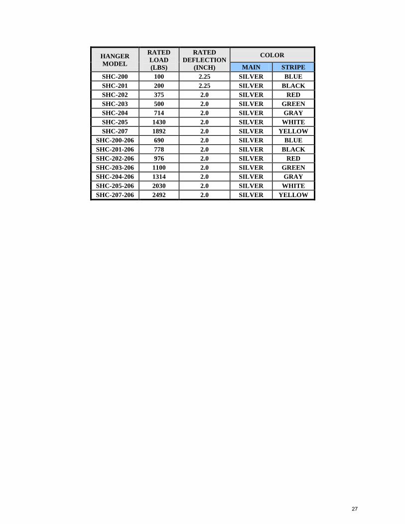
HANGER
MODEL
RATED
LOAD
(LBS)
RATED
DEFLECTION
(INCH)
COLOR
MAIN STRIPE
SHC-200 100 2.25 SILVER BLUE
SHC-201 200 2.25 SILVER BLACK
SHC-202 375 2.0 SILVER RED
SHC-203 500 2.0 SILVER GREEN
SHC-204 714 2.0 SILVER GRAY
SHC-205 1430 2.0 SILVER WHITE
SHC-207 1892 2.0 SILVER YELLOW
SHC-200-206 690 2.0 SILVER BLUE
SHC-201-206 778 2.0 SILVER BLACK
SHC-202-206 976 2.0 SILVER RED
SHC-203-206 1100 2.0 SILVER GREEN
SHC-204-206 1314 2.0 SILVER GRAY
SHC-205-206 2030 2.0 SILVER WHITE
SHC-207-206 2492 2.0 SILVER YELLOW
27
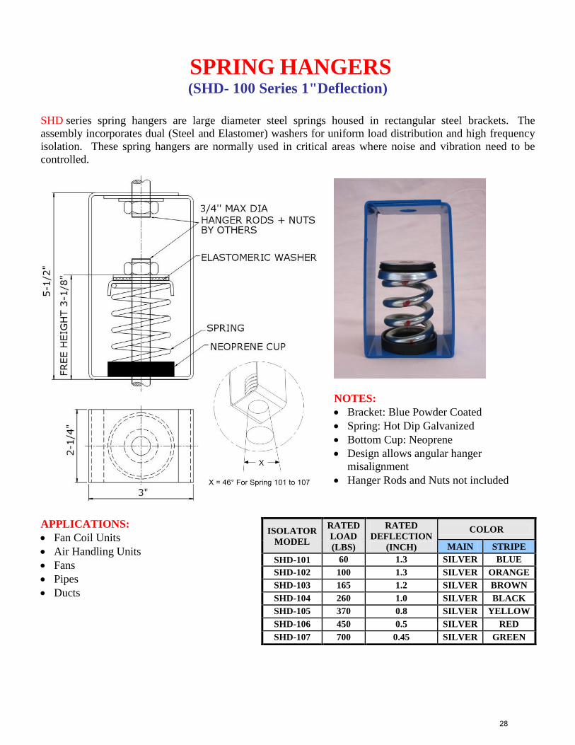
SPRING HANGERS (SHD- 100 Series 1"Deflection)
SHD series spring hangers are large diameter steel springs housed in rectangular steel brackets. The
assembly incorporates dual (Steel and Elastomer) washers for uniform load distribution and high frequency
isolation. These spring hangers are normally used in critical areas where noise and vibration need to be
controlled.
NOTES:
Bracket: Blue Powder Coated
Spring: Hot Dip Galvanized
Bottom Cup: Neoprene
Design allows angular hanger
misalignment
Hanger Rods and Nuts not included
APPLICATIONS:
Fan Coil Units
Air Handling Units
Fans
Pipes
Ducts
ISOLATOR
MODEL
RATED
LOAD
(LBS)
RATED
DEFLECTION
(INCH)
COLOR
MAIN STRIPE
SHD-101 60 1.3 SILVER BLUE
SHD-102 100 1.3 SILVER ORANGE
SHD-103 165 1.2 SILVER BROWN
SHD-104 260 1.0 SILVER BLACK
SHD-105 370 0.8 SILVER YELLOW
SHD-106 450 0.5 SILVER RED
SHD-107 700 0.45 SILVER GREEN
28
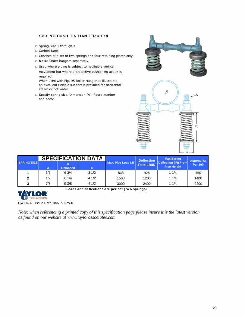
SPRING CUSHION HANGER #178
□ Spring Size 1 through 3
□ Carbon Steel
□ Consists of a set of two springs and four retaining plates only.
□ Note: Order hangers separately.
□ Used where piping is subject to negligible vertical
movement but where a protective cushioning action is
required.When used with Fig. 95 Roller Hanger as illustrated, an excellent flexible support is provided for horizontal steam or hot water
□ Specify spring size, Dimension "A", figure numberand name.
1 535 428 4502 1500 1200 14003 3000 2400 2200
Loads and deflections are per set (two springs)
QWI 4.3.1 Issue Date Mar/09 Rev.0
Note: when referencing a printed copy of this specification page please insure it is the latest version as found on our website at www.taylorassociates.com
1 1/41 1/41 1/4
7/8 9 3/84 1/24 1/2
1/2 6 1/43/8
SPRING SIZE
AB
Unloaded C6 3/4 3 1/2
Approx. Wt Per 100Max. Pipe Load LB Deflection
Rate LB/IN
Max Spring Deflection (IN) From
Free Height
SPECIFICATION DATA
29
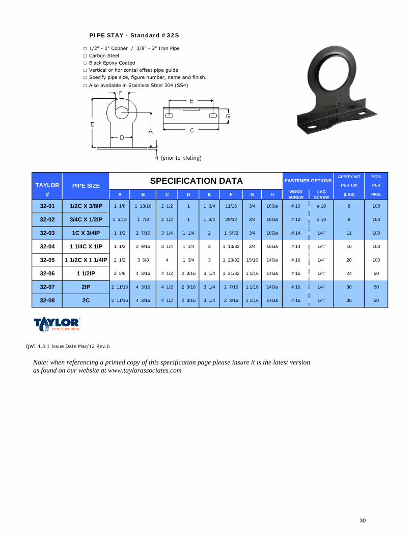
PIPE STAY - Standard #32S
□ 1/2" - 2" Copper / 3/8" - 2" Iron Pipe
□ Carbon Steel
□ Black Epoxy Coated
□ Vertical or horizontal offset pipe guide
□ Specify pipe size, figure number, name and finish.
□ Also available in Stainless Steel 304 (SS4)
APPR'X WT PC'S
TAYLOR PER 100 PER
# A B C D E F G H WOOD SCREW
LAG SCREW
(LBS) PKG.
QWI 4.3.1 Issue Date Mar/12 Rev.6
Note: when referencing a printed copy of this specification page please insure it is the latest version as found on our website at www.taylorassociates.com
2C
3/4C X 1/2IP
1C X 3/4IP
1 1/4C X 1IP
1 1/2C X 1 1/4IP
1 1/2IP
2IP
32-06
32-07
32-08
32-01
32-02
32-03
32-04
32-05
1 1/8 1 13/16
PIPE SIZE
11/2C X 3/8IP 2 1/2
SPECIFICATION DATA
8 100
1003/4 8
2 1/2 1 3/4 3/41 29/32
1 1/2 2 7/16
1 3/16 1 7/8
3 1/4 2
16
1 1/4 # 14 1/4"1 5/32
1 1/2 2 9/16 3 1/4 2 100
100
3
24
20
# 16 1/4"
3/4
3/4 11
2 1/2 3 5/8
50
100
2 5/8 4 3/16 4 1/2 3 1/4 1 1/16
15/164
1/4"
# 16 1/4"
# 141 13/32
1 23/32
2 11/16 4 3/16 30
2 11/16 4 3/16 1 1/16
1 1/16
1/4"
# 16 1/4"
30 50
50
4 1/2
4 1/2 3 1/4
3 1/4 # 1614Ga
1 1/4
1 3/4
2 3/16
2 3/16
2 3/16
FASTENER OPTIONS
# 10 # 10
# 10 # 10
1 3/4 11/16
1 31/32
2 7/16
2 3/16
16Ga
16Ga
16Ga
16Ga
14Ga
14Ga
14Ga
30
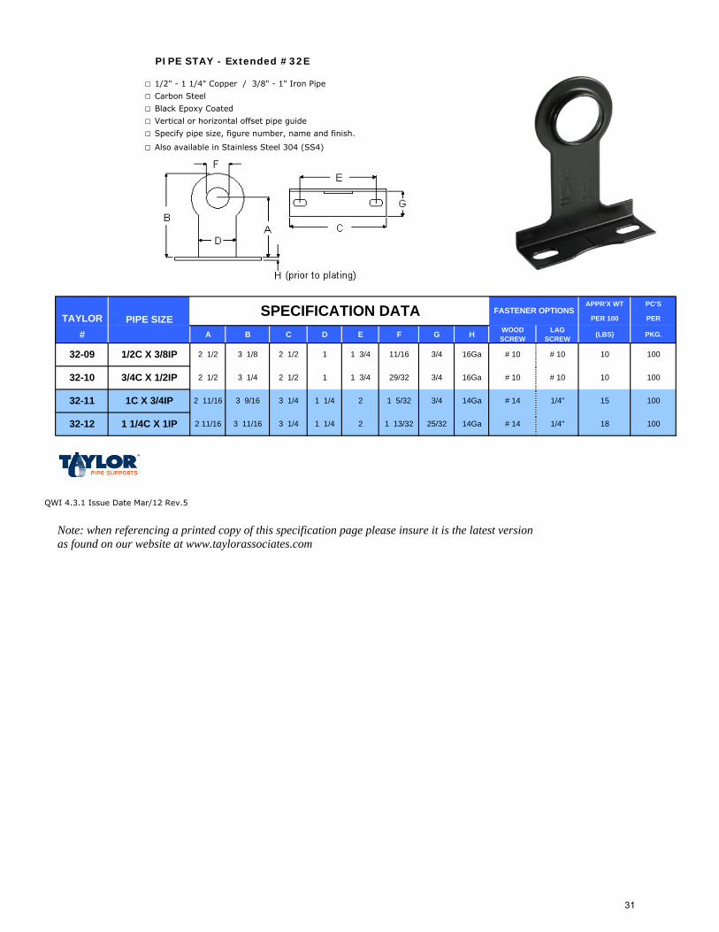
PIPE STAY - Extended #32E
□ 1/2" - 1 1/4" Copper / 3/8" - 1" Iron Pipe
□ Carbon Steel
□ Black Epoxy Coated
□ Vertical or horizontal offset pipe guide
□ Specify pipe size, figure number, name and finish.
□ Also available in Stainless Steel 304 (SS4)
APPR'X WT PC'S
TAYLOR PER 100 PER
# A B C D E F G H WOOD SCREW
LAG SCREW (LBS) PKG.
QWI 4.3.1 Issue Date Mar/12 Rev.5
Note: when referencing a printed copy of this specification page please insure it is the latest version as found on our website at www.taylorassociates.com
FASTENER OPTIONS
# 10 # 10
# 10 # 10
1 3/4
1/4"1 1/42 11/16 3 11/16 3 1/4 100
100
25/32
3/4 1514Ga
14Ga2
3 1/4 2
18
1 1/4 # 14 1/4"
# 14
1 5/32
1 13/32
2 11/16 3 9/16
2 1/2 3 1/4 1 3/4 3/41 29/32
11/16
SPECIFICATION DATA
10 100
1003/4 1016Ga
16Ga2 1/2
2 1/2 3 1/8
PIPE SIZE
11/2C X 3/8IP 2 1/2
3/4C X 1/2IP
1C X 3/4IP
1 1/4C X 1IP
32-09
32-10
32-11
32-12
31
PIPE STAY - Double #32D
□ 1/2" - 3/4" Copper / 3/8" - 1/2" Iron Pipe
□ Carbon Steel
□ Black Epoxy Coated
□ Vertical or horizontal offset pipe guide
□ Specify pipe size, figure number, name and finish.
APPR'X WT PC'S
TAYLOR PER 100 PER
# A B C D E WOOD SCREW
LAG SCREW (LBS) PKG.
QWI 4.3.1 Issue Date May/01 Rev.1
Note: when referencing a printed copy of this specification page please insure it is the latest version as found on our website at www.taylorassociates.com
3/4C X 1/2IP
32-13
32-14
1 3/16 1 7/8
PIPE SIZE SPECIFICATION DATA
31/2C X 3/8IP 2 1/2
11 50
5011
2 1/2 1 3/431 3/16 1 7/8
FASTENER OPTIONS
# 10 # 10
# 10 # 10
1 3/4
32
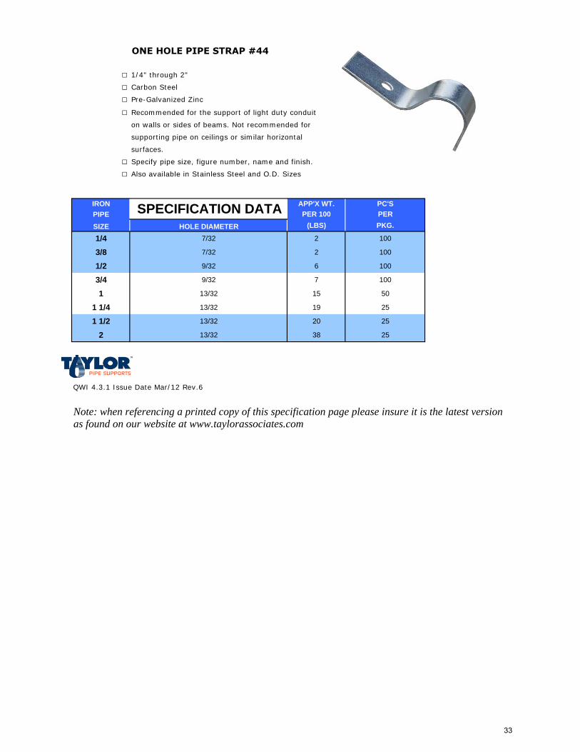
ONE HOLE PIPE STRAP #44
□ 1/4" through 2"
□ Carbon Steel
□ Pre-Galvanized Zinc
□ Recommended for the support of light duty conduit
on walls or sides of beams. Not recommended for
supporting pipe on ceilings or similar horizontal
surfaces.
□ Specify pipe size, figure number, name and finish.
□ Also available in Stainless Steel and O.D. Sizes
IRON APP'X WT. PC'SPIPE PER 100 PERSIZE HOLE DIAMETER (LBS) PKG.
1/4 7/32 2 100
3/8 7/32 2 100
1/2 9/32 6 100
3/4 9/32 7 100
1 13/32 15 50
1 1/4 13/32 19 25
1 1/2 13/32 20 25
2 13/32 38 25
QWI 4.3.1 Issue Date Mar/12 Rev.6
Note: when referencing a printed copy of this specification page please insure it is the latest version as found on our website at www.taylorassociates.com
SPECIFICATION DATA
33
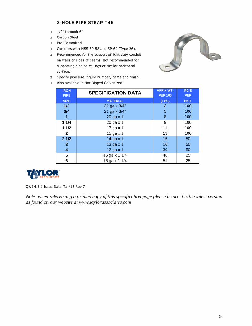
2-HOLE PIPE STRAP #45
□ 1/2" through 6"
□ Carbon Steel
□ Pre-Galvanized
□ Complies with MSS SP-58 and SP-69 (Type 26).
□ Recommended for the support of light duty conduit
on walls or sides of beams. Not recommended for
supporting pipe on ceilings or similar horizontal
surfaces.
□ Specify pipe size, figure number, name and finish.
□ Also available in Hot Dipped Galvanized
IRON PC'SPIPE PERSIZE PKG.
QWI 4.3.1 Issue Date Mar/12 Rev.7
Note: when referencing a printed copy of this specification page please insure it is the latest version as found on our website at www.taylorassociates.com
20 ga x 11 1/41 1/2
2
1009 1008
1005 1003
100
50
100
5050
APP'X WT.PER 100
39
11
(LBS)
161513
SPECIFICATION DATAMATERIAL
21 ga x 3/4"21 ga x 3/4"
1/23/41 20 ga x 1
13 ga x 1
17 ga x 1
5 16 ga x 1 1/4
15 ga x 114 ga x 1
4 12 ga x 13
2 1/2
46 256 16 ga x 1 1/4 51 25
34
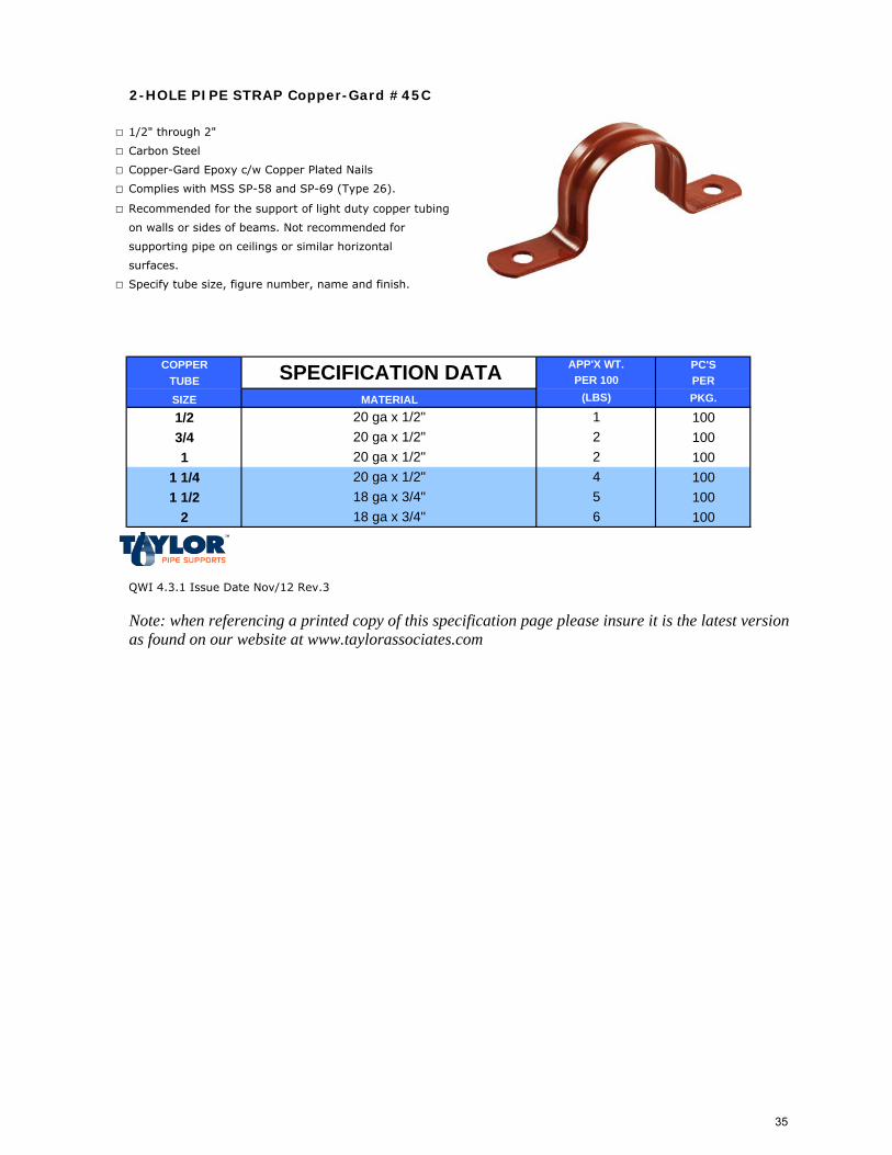
2-HOLE PIPE STRAP Copper-Gard #45C
□ 1/2" through 2"
□ Carbon Steel
□ Copper-Gard Epoxy c/w Copper Plated Nails
□ Complies with MSS SP-58 and SP-69 (Type 26).
□ Recommended for the support of light duty copper tubing
on walls or sides of beams. Not recommended for
supporting pipe on ceilings or similar horizontal
surfaces.
□ Specify tube size, figure number, name and finish.
COPPER PC'STUBE PERSIZE PKG.
1/2 1003/4 1001 100
1 1/4 1001 1/2 100
2 100
QWI 4.3.1 Issue Date Nov/12 Rev.3
Note: when referencing a printed copy of this specification page please insure it is the latest version as found on our website at www.taylorassociates.com
APP'X WT.PER 100
5
(LBS)
1
6
422
18 ga x 3/4"
20 ga x 1/2"18 ga x 3/4"
SPECIFICATION DATAMATERIAL
20 ga x 1/2"20 ga x 1/2"20 ga x 1/2"
35
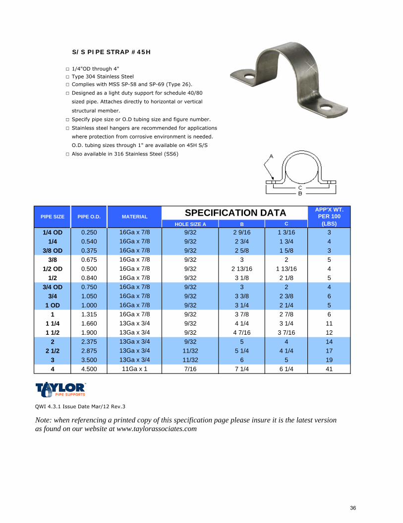
S/S PIPE STRAP #45H
□ 1/4"OD through 4"
□ Type 304 Stainless Steel
□ Complies with MSS SP-58 and SP-69 (Type 26).
□ Designed as a light duty support for schedule 40/80
sized pipe. Attaches directly to horizontal or vertical
structural member.
□ Specify pipe size or O.D tubing size and figure number.
□ Stainless steel hangers are recommended for applications
where protection from corrosive environment is needed.
O.D. tubing sizes through 1" are available on 45H S/S
□ Also available in 316 Stainless Steel (SS6)
APP'X WT.PER 100
HOLE SIZE A B C (LBS)1/4 OD 0.250 9/32 2 9/16 1 3/16 3
1/4 0.540 9/32 2 3/4 1 3/4 43/8 OD 0.375 9/32 2 5/8 1 5/8 3
3/8 0.675 9/32 3 2 51/2 OD 0.500 9/32 2 13/16 1 13/16 4
1/2 0.840 9/32 3 1/8 2 1/8 53/4 OD 0.750 9/32 3 2 4
3/4 1.050 9/32 3 3/8 2 3/8 61 OD 1.000 9/32 3 1/4 2 1/4 5
1 1.315 9/32 3 7/8 2 7/8 61 1/4 1.660 9/32 4 1/4 3 1/4 111 1/2 1.900 9/32 4 7/16 3 7/16 12
2 2.375 9/32 5 4 142 1/2 2.875 11/32 5 1/4 4 1/4 17
3 3.500 11/32 6 5 194 4.500 7/16 7 1/4 6 1/4 41
QWI 4.3.1 Issue Date Mar/12 Rev.3
Note: when referencing a printed copy of this specification page please insure it is the latest version as found on our website at www.taylorassociates.com
13Ga x 3/4
16Ga x 7/8
16Ga x 7/816Ga x 7/816Ga x 7/8
16Ga x 7/816Ga x 7/816Ga x 7/8
16Ga x 7/8
13Ga x 3/4
13Ga x 3/4
11Ga x 1
13Ga x 3/4
13Ga x 3/4
16Ga x 7/8
PIPE SIZE PIPE O.D. MATERIAL SPECIFICATION DATA
16Ga x 7/8
36
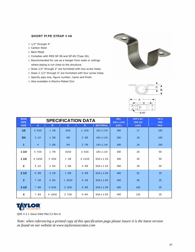
SHORT PIPE STRAP #46
□ 1/2" through 4"
□ Carbon Steel
□ Bare Metal
□ Complies with MSS SP-58 and SP-69 (Type 26).
□ Recommended for use as a hanger from walls or ceilings
where piping is run close to the structure.
□ Sizes 1/2" through 2" are furnished with two screw holes.
□ Sizes 2 1/2" through 4" are furnished with four screw holes.
□ Specify pipe size, figure number, name and finish.
□ Also available in Electro-Plated Zinc
IRON REC. APP'X WT. PC'SPIPE MAX. LOAD PER 100 PERSIZE A B C D MATERIAL (LBS.) (LBS) PKG.
QWI 4.3.1 Issue Date Mar/12 Rev.6
Note: when referencing a printed copy of this specification page please insure it is the latest version as found on our website at www.taylorassociates.com
493/16 x 1 1/4
953/16 x 1 3/4 400
400
300
25
400
4 7 3/4 4 13/16 2 7/16 6 6/4 3/16 x 1 3/4 400 116
25
3 1/2 7 3/8 4 5/16 2 3/16 6 3/8 3/16 x 1 3/4 25105
6 1/83 7 1/8 3 3/4 1 15/16
50
2 1/2 6 3/8 3 1/8 1 5/8 5 3/8 3/16 x 1 3/4 2591
4 3/8
300
2 5 1/2 2 3/4 1 3/8
26 50
1 1/2 4 13/16 2 3/16 1 1/8 3 11/16 3/16 x 1 1/4 5040
3 5/16 1/8 x 1 1/4 300
300
1 1/4 4 7/16 1 7/8 15/16
19 100
1 4 1 5/8 3/4 2 7/8 1/8 x 1 1/4 10024
100
3/4 3 1/2 1 3/8 5/8 2 3/8 1/8 x 1 1/4 300
300 171/2 3 3/16 1 1/8
SPECIFICATION DATA
9/16 2 1/16 1/8 x 1 1/4
37
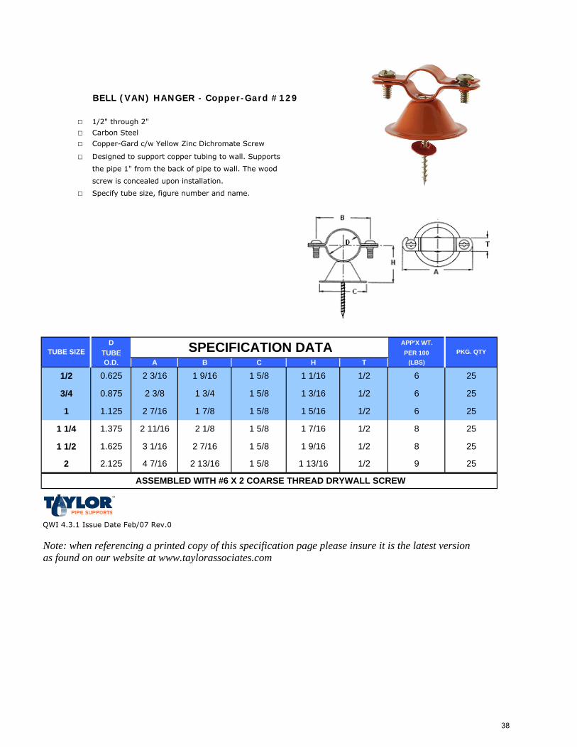
BELL (VAN) HANGER - Copper-Gard #129
□ 1/2" through 2"
□ Carbon Steel
□ Copper-Gard c/w Yellow Zinc Dichromate Screw
□ Designed to support copper tubing to wall. Supports
the pipe 1" from the back of pipe to wall. The wood
screw is concealed upon installation.
□ Specify tube size, figure number and name.
D APP'X WT.TUBE PER 100O.D. A B C H T (LBS)
QWI 4.3.1 Issue Date Feb/07 Rev.0
Note: when referencing a printed copy of this specification page please insure it is the latest version as found on our website at www.taylorassociates.com
PKG. QTY
ASSEMBLED WITH #6 X 2 COARSE THREAD DRYWALL SCREW
1 9/16 1 5/8 1 1/16
1 1/2
251 5/8 1 13/16 1/2 9
1 5/8 1 9/16 1/2 8
2 2.125 4 7/16 2 13/16
1.625 3 1/16 2 7/16
25
1 5/8 1 7/16 1/2 8 25
25
1 1/4 1.375 2 11/16 2 1/8
6 25
1 1.125 2 7/16 1 7/8 1 5/8 1 5/16 1/2 6
6 25
3/4 0.875 2 3/8 1 3/4 1 5/8 1 3/16 1/2
1/21/2 0.625 2 3/16
SPECIFICATION DATATUBE SIZE
38
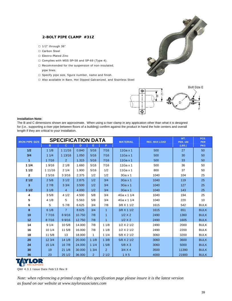
2-BOLT PIPE CLAMP #31Z
□ 1/2" through 36"
□ Carbon Steel
□ Electro-Plated Zinc
□ Complies with MSS SP-58 and SP-69 (Type 4).
□ Recommended for the suspension of non-insulated,
pipe lines.
□ Specify pipe size, figure number, name and finish.
□ Also available in Bare, Hot Dipped Galvanized, and Stainless Steel
Installation Note:The B and C dimensions shown are approximate. When using a riser clamp in any application other than what it is designed for (i.e.. supporting a riser pipe between floors of a building) confirm against the product in hand the hole centers and overall length if they are critical to your installation.
WT. PCS.PER. 100 PER
B C D E F (LBS.) PKG
1/2 1 1/8 1 11/16 0.840 5/16 7/16 27 503/4 1 1/4 1 13/16 1.050 5/16 7/16 30 501 1 7/16 2 1.315 5/16 7/16 33 50
1 1/4 1 9/16 2 1/8 1.660 5/16 7/16 36 501 1/2 1 11/16 2 1/4 1.900 5/16 1/2 37 50
2 2 5/16 3 3/16 2.375 1/2 1/2 104 252 1/2 2 5/8 3 1/2 2.875 1/2 3/4 119 25
3 2 7/8 3 3/4 3.500 1/2 3/4 127 253 1/2 3 1/8 4 4.000 1/2 3/4 143 25
4 3 5/8 4 1/2 4.500 5/8 3/4 194 255 4 1/8 5 5.563 5/8 3/4 220 106 5 5 7/8 6.625 3/4 7/8 542 BULK8 6 1/8 7 8.625 3/4 1 651 BULK
10 7 7/16 8 9/16 10.750 7/8 1 1360 BULK12 8 7/16 9 9/16 12.750 7/8 1 1605 BULK14 9 1/4 10 5/8 14.000 7/8 1 1/8 2000 BULK16 10 1/4 11 5/8 16.000 7/8 1 1/8 2200 BULK18 11 5/8 13 18.000 1 1 1/4 3200 BULK20 12 3/4 14 1/8 20.000 1 1/8 1 3/8 3600 BULK24 15 1/4 16 7/8 24.000 1 1/4 1 5/8 5000 BULK30 19 21 1/8 30.000 1 3/4 2 11390 BULK36 23 25 1/2 36.000 2 2 1/2 21900 BULK
QWI 4.3.1 Issue Date Feb/13 Rev.9
Note: when referencing a printed copy of this specification page please insure it is the latest version as found on our website at www.taylorassociates.com
1 X 5 4000
5/8 X 3 30603/4 X 4 3500
5/8 X 2 1/2
1/2 X 21/2 X 2
1/2 X 2 1/21/2 X 2 1/2
4Ga x 1 1/43/8 X 1 1/23/8 X 1 1/2
5/8 X 2 1/2
11Ga x 111Ga x 111Ga x 111Ga x 13Ga x 13Ga x 13Ga x 13Ga x 1
4Ga x 1 1/4
11Ga x 1
IRON PIPE SIZE SPECIFICATION DATA REC. MAX LOAD MATERIAL
500500500500800
1040104010401040104010401615
249030603060
1615249024902490
39
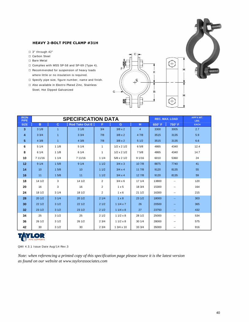
HEAVY 2-BOLT PIPE CLAMP #31H
□ 3" through 42"
□ Carbon Steel
□ Bare Metal
□ Complies with MSS SP-58 and SP-69 (Type 4).
□ Recommended for suspension of heavy loads
where little or no insulation is required.
□ Specify pipe size, figure number, name and finish.
□ Also available in Electro Plated Zinc, Stainless
Steel, Hot Dipped Galvanized
IRON APP'X WT.PIPE LBS.
SIZE B C Rod Take Out E F G H 650° F 750° F EACH
QWI 4.3.1 Issue Date Aug/14 Rev.3
Note: when referencing a printed copy of this specification page please insure it is the latest version as found on our website at www.taylorassociates.com
SPECIFICATION DATA REC. MAX. LOAD
575
916
303
365
432
534
59
120
164
215
14.7
24
41
55
2.7
5.9
6.6
12.4
3/4 x 4 11 7/8
2 1/2
2 1/2
2
2 1/2
813591201 1/2 3/4 x 4 12 7/816 11 1 5/8 11
14 10
1 1/2 x 2 1/2
1 5/8 10 1 1/2
12 9 1/4 1 5/8
8135
77408875
9120
43404865
6010
7 5/8
5360
9 1/4
1 1/4 5/8 x 2 1/2 9 1/16
1 1/2 3/4 x 3 10 7/8
10 7 11/16 1 1/4 7 11/16
5 1/4 1 1/8
8 6 1/4 1 1/8 6 1/4
4 3 3/4 1
5 4 3/8 1
3 3/4
5 1/46
3135
300533003/4 3/8 x 2 4
3/8 x 2 4 7/8 3515
4 3/8
1/2 x 2 1/2
7/8 3/8 x 2
4340
31353515
4865
3 3 1/8 1 3 1/8
6 5/8
5 1/2
1
7/8
24
28
30
20
32
34
36
42
16
18 1/2
20 1/2
22 1/2
16
3 1/4
3 1/4
3 1/2
3
18 1/2
23 1/2
25
3 1/2
3 1/2
20 1/2
22 1/2
23 1/2
2 1/4
25
1 x 6 21 1/2
23 1/2
1 1/4 x 7 26
1 x 8
1 1/4 x 8 27
--
16300 --
15300 --
2 3/4
--
18000 --
20500 --
1 1/2 x 8 28 1/2
--
--
3 1/2 30 2 3/4 1 3/4 x 10 33 3/4
1 1/2 x 8 30 1/4
--30
2 3/4 x 6 17 1/4
2 1 x 5 18 3/4
26 1/2 3 1/2 26 1/2
18 14 1/2 3 14 1/2
35000
28000
23750
13800
25000
40
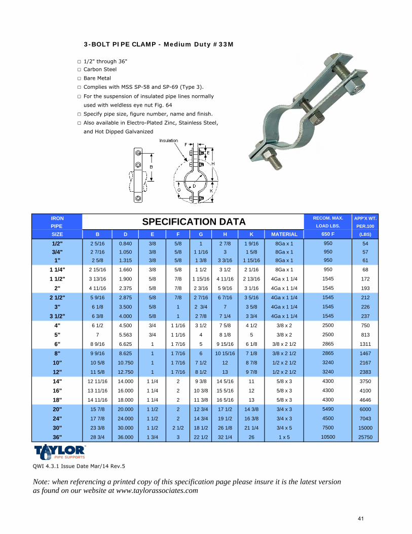
3-BOLT PIPE CLAMP - Medium Duty #33M
□ 1/2" through 36"
□ Carbon Steel
□ Bare Metal
□ Complies with MSS SP-58 and SP-69 (Type 3).
□ For the suspension of insulated pipe lines normally
used with weldless eye nut Fig. 64
□ Specify pipe size, figure number, name and finish.
□ Also available in Electro-Plated Zinc, Stainless Steel,
and Hot Dipped Galvanized
IRON APP'X WT.
PIPE PER.100
SIZE B D E F G H K MATERIAL (LBS)
1/2" 2 5/16 0.840 3/8 5/8 1 2 7/8 1 9/16 8Ga x 1 54
3/4" 2 7/16 1.050 3/8 5/8 1 1/16 3 1 5/8 8Ga x 1 57
1" 2 5/8 1.315 3/8 5/8 1 3/8 3 3/16 1 15/16 8Ga x 1 61
1 1/4" 2 15/16 1.660 3/8 5/8 1 1/2 3 1/2 2 1/16 8Ga x 1 68
1 1/2" 3 13/16 1.900 5/8 7/8 1 15/16 4 11/16 2 13/16 4Ga x 1 1/4 172
2" 4 11/16 2.375 5/8 7/8 2 3/16 5 9/16 3 1/16 4Ga x 1 1/4 193
2 1/2" 5 9/16 2.875 5/8 7/8 2 7/16 6 7/16 3 5/16 4Ga x 1 1/4 212
3" 6 1/8 3.500 5/8 1 2 3/4 7 3 5/8 4Ga x 1 1/4 226
3 1/2" 6 3/8 4.000 5/8 1 2 7/8 7 1/4 3 3/4 4Ga x 1 1/4 237
4" 6 1/2 4.500 3/4 1 1/16 3 1/2 7 5/8 4 1/2 3/8 x 2 750
5" 7 5.563 3/4 1 1/16 4 8 1/8 5 3/8 x 2 813
6" 8 9/16 6.625 1 1 7/16 5 9 15/16 6 1/8 3/8 x 2 1/2 1311
8" 9 9/16 8.625 1 1 7/16 6 10 15/16 7 1/8 3/8 x 2 1/2 1467
10" 10 5/8 10.750 1 1 7/16 7 1/2 12 8 7/8 1/2 x 2 1/2 2167
12" 11 5/8 12.750 1 1 7/16 8 1/2 13 9 7/8 1/2 x 2 1/2 2383
14" 12 11/16 14.000 1 1/4 2 9 3/8 14 5/16 11 5/8 x 3 3750
16" 13 11/16 16.000 1 1/4 2 10 3/8 15 5/16 12 5/8 x 3 4100
18" 14 11/16 18.000 1 1/4 2 11 3/8 16 5/16 13 5/8 x 3 4646
20" 15 7/8 20.000 1 1/2 2 12 3/4 17 1/2 14 3/8 3/4 x 3 6000
24" 17 7/8 24.000 1 1/2 2 14 3/4 19 1/2 16 3/8 3/4 x 3 7043
30" 23 3/8 30.000 1 1/2 2 1/2 18 1/2 26 1/8 21 1/4 3/4 x 5 15000
36" 28 3/4 36.000 1 3/4 3 22 1/2 32 1/4 26 1 x 5 25750
QWI 4.3.1 Issue Date Mar/14 Rev.5
Note: when referencing a printed copy of this specification page please insure it is the latest version as found on our website at www.taylorassociates.com
RECOM. MAX.
LOAD LBS.SPECIFICATION DATA650 F
950950
950
1545
1545
1545
1545
1545
2500
2500
2865
2865
7500
10500
950
4300
5490
4500
3240
3240
4300
4300
41
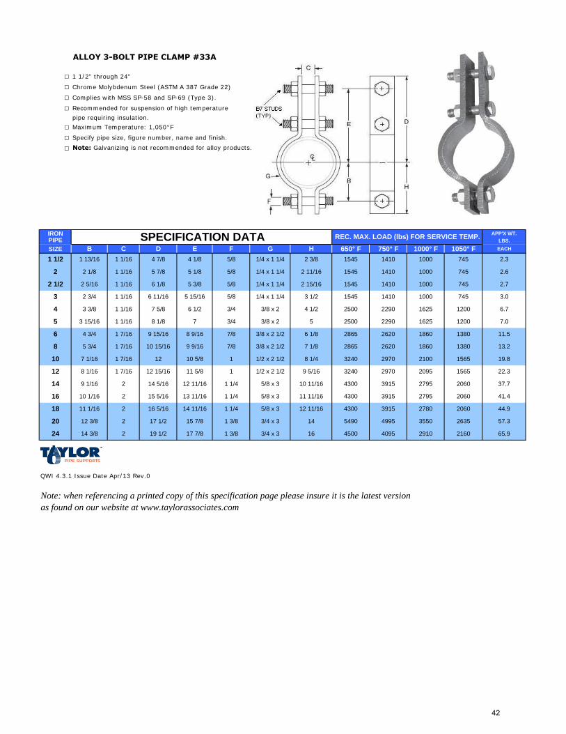
ALLOY 3-BOLT PIPE CLAMP #33A
□ 1 1/2" through 24"
□ Chrome Molybdenum Steel (ASTM A 387 Grade 22)
□ Complies with MSS SP-58 and SP-69 (Type 3).
□ Recommended for suspension of high temperature
pipe requiring insulation.
□ Maximum Temperature: 1,050°F
□ Specify pipe size, figure number, name and finish.
□ Note: Galvanizing is not recommended for alloy products.
IRON APP'X WT.PIPE LBS.
SIZE B C D E F G H 650° F 750° F 1000° F 1050° F EACH
QWI 4.3.1 Issue Date Apr/13 Rev.0
Note: when referencing a printed copy of this specification page please insure it is the latest version as found on our website at www.taylorassociates.com
1000
1000
1000
1625
1410
1410
1410
3915
2620
2970
SPECIFICATION DATA REC. MAX. LOAD (lbs) FOR SERVICE TEMP.
44.9
6.7
7.0
11.5
13.2
2.3
2.6
1410
57.3
65.9
19.8
22.3
37.7
41.4
2.7
3.0
7/8 3/8 x 2 1/2 7 1/8
17 7/8
13 11/16
15 7/8
15 5/16
1 3/8 3/4 x 3
1565324010 5/8 1 1/2 x 2 1/2 8 1/4
2795
8 5 3/4
2100
6 4 3/4 1 7/16
1 7/16 10 15/16 9 9/16
10
1380
13802865
2865 1860
7 5/8
2290
2620
12002500
2500
6 1/2 3/4 2290
1625 1200
9 15/16
7 3/4 3/8 x 2
8 9/16 7/8 3/8 x 2 1/2 18606 1/8
5 3 15/16 1 1/16 8 1/8
2 3/4 1 1/16
4 3 3/8 1 1/16
2 2 1/8 1 1/16
2 1/2 2 5/16 1 1/16
5 7/8
6 11/163
7455/8 1/4 x 1 1/4 1545
6 1/8
5/8
5 3/8
74515454 1/8 5/8 1/4 x 1 1/4 2 3/8 1000
5/8
745
74515452 15/16
3 1/2
2 11/16
1545
1 1/2 1 13/16 1 1/16 4 7/8
1/4 x 1 1/4
1/4 x 1 1/4
5 15/16
5 1/8
16
18
20
14
24
14 5/16
10 1/16
11 1/16
12 3/8
9 1/16
2
2
2
2
14 3/8 2
16 5/16
17 1/2
19 1/2
7 1/16 1 7/16 12
14
12 11/16 1 1/4 5/8 x 3
1 1/414 11/16 5/8 x 3
1 3/8 3/4 x 3 16
4 1/2
5
1 1/4 5/8 x 3 11 11/16
9 5/16
3/8 x 2
1565
4300 2060
4300 2060
2970
3915
3915
3240 2095
5490 2635
21604500
4995
4095
3550
2910
20602780
10 11/16
430012 11/16
2795
11 5/8 1 1/2 x 2 1/212 8 1/16 1 7/16 12 15/16
42
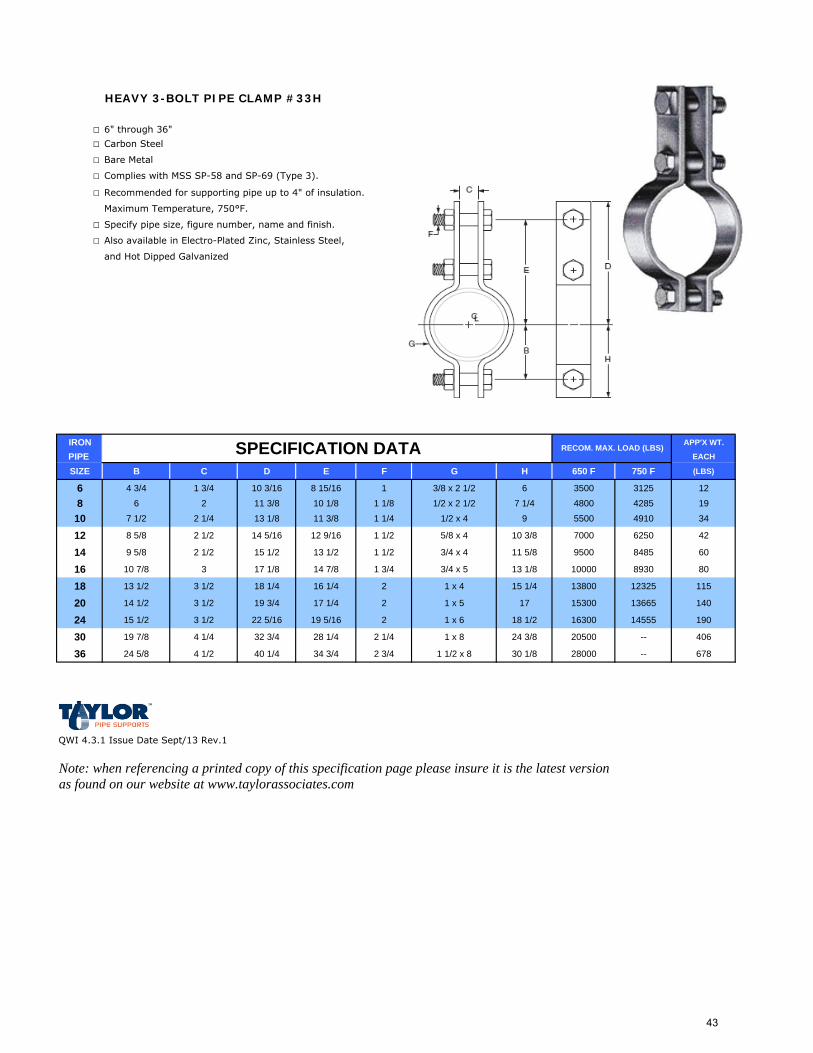
HEAVY 3-BOLT PIPE CLAMP #33H
□ 6" through 36"
□ Carbon Steel
□ Bare Metal
□ Complies with MSS SP-58 and SP-69 (Type 3).
□ Recommended for supporting pipe up to 4" of insulation.
Maximum Temperature, 750°F.
□ Specify pipe size, figure number, name and finish.
□ Also available in Electro-Plated Zinc, Stainless Steel,
and Hot Dipped Galvanized
IRON APP'X WT.
PIPE EACH
SIZE B C D E F G H 650 F 750 F (LBS)
6 4 3/4 1 3/4 10 3/16 8 15/16 1 3/8 x 2 1/2 6 3500 3125 12
8 6 2 11 3/8 10 1/8 1 1/8 1/2 x 2 1/2 7 1/4 4800 4285 19
10 7 1/2 2 1/4 13 1/8 11 3/8 1 1/4 1/2 x 4 9 5500 4910 34
12 8 5/8 2 1/2 14 5/16 12 9/16 1 1/2 5/8 x 4 10 3/8 7000 6250 42
14 9 5/8 2 1/2 15 1/2 13 1/2 1 1/2 3/4 x 4 11 5/8 9500 8485 60
16 10 7/8 3 17 1/8 14 7/8 1 3/4 3/4 x 5 13 1/8 10000 8930 80
18 13 1/2 3 1/2 18 1/4 16 1/4 2 1 x 4 15 1/4 13800 12325 115
20 14 1/2 3 1/2 19 3/4 17 1/4 2 1 x 5 17 15300 13665 140
24 15 1/2 3 1/2 22 5/16 19 5/16 2 1 x 6 18 1/2 16300 14555 190
30 19 7/8 4 1/4 32 3/4 28 1/4 2 1/4 1 x 8 24 3/8 20500 -- 406
36 24 5/8 4 1/2 40 1/4 34 3/4 2 3/4 1 1/2 x 8 30 1/8 28000 -- 678
QWI 4.3.1 Issue Date Sept/13 Rev.1
Note: when referencing a printed copy of this specification page please insure it is the latest version as found on our website at www.taylorassociates.com
SPECIFICATION DATA RECOM. MAX. LOAD (LBS)
43
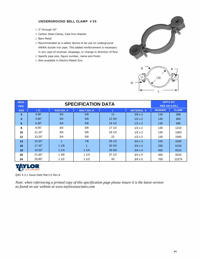
UNDERGROUND BELL CLAMP #35
□ 3" through 24"
□ Carbon Steel Clamp, Cast Iron Washer
□ Bare Metal
□ Recommended as a safety device to be use on underground
AWWA ductile iron pipe. This added reinforcement is necessary
in any case of reversal, stoppage, or change in direction of flow.
□ Specify pipe size, figure number, name and finish.
□ Also available in Electro-Plated Zinc
IRON PIPE SIZE MATERIAL S WASHER CLAMP
3 3/8 x 2 130 5984 1/2 x 2 130 8006 1/2 x 2 130 9958 1/2 x 2 130 121010 1/2 x 2 130 136312 1/2 x 2 130 156514 3/4 x 3 230 418016 3/4 x 4 290 619318 3/4 x 4 465 651520 3/4 x 5 465 922524 3/4 x 5 700 12274
QWI 4.3.1 Issue Date Mar/12 Rev.6
Note: when referencing a printed copy of this specification page please insure it is the latest version as found on our website at www.taylorassociates.com
25.80" 1 1/2 1 1/2 43
22
1 3/8 1 1/419.50" 1 1/4 1 1/4 34 5/817.40"
37 1/221.60"
1 1/8 1 30 3/428 1/2
ROD DIA. A
15.30" 1 7/8
3/4 5/83/4
13.20" 3/4 5/8
12 3/43/4 5/8 12
APP'X WT.PER 100 (LBS.)
5/8 15 1/2
BOLT DIA. D L
SPECIFICATION DATAI. D.
3.96"4.80"6.90"
17 1/211.10" 3/4 5/8 19 1/29.05" 3/4 5/8
S A
I.D.
L
D
44
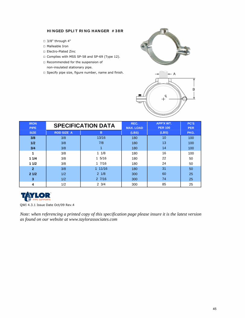
HINGED SPLIT RING HANGER #38R
□ 3/8" through 4"
□ Malleable Iron
□ Electro-Plated Zinc
□ Complies with MSS SP-58 and SP-69 (Type 12).
□ Recommended for the suspension of
non-insulated stationary pipe.
□ Specify pipe size, figure number, name and finish.
IRON REC. PC'SPIPE MAX. LOAD PERSIZE ROD SIZE A (LBS) PKG.
3/8 3/8 180 1001/2 3/8 180 1003/4 3/8 180 1001 3/8 180 100
1 1/4 3/8 180 501 1/2 3/8 180 50
2 3/8 180 502 1/2 1/2 300 25
3 1/2 300 254 1/2 300 25
QWI 4.3.1 Issue Date Oct/09 Rev.4
Note: when referencing a printed copy of this specification page please insure it is the latest version as found on our website at www.taylorassociates.com
852 3/4
1 11/16 31
2 7/16 74
221 5/16
B
SPECIFICATION DATA
1310
APP'X WT.PER 100
(LBS)13/16
24
2 1/8 60
1 7/16
1 1/81
7/8
1614
45
SPLIT RING HANGER #38R SS
□ 3/8" through 4"
□ 304 (SS4) and 316 (SS6) Stainless Steel
□ Complies with MSS SP-58 and SP-69 (Type 12).
□ Recommended for the suspension of non-insulated
stationary pipe and where protection from
corrosive environement is required.
□ Specify pipe size, figure number, name and type.
REC. PC'SMAX. LOAD PER
ROD SIZE A (LBS) PKG.
3/8 3/8 180 1001/2 3/8 180 1003/4 3/8 180 1001 3/8 180 100
1 1/4 3/8 180 501 1/2 3/8 180 50
2 3/8 180 502 1/2 1/2 300 25
3 1/2 300 254 1/2 300 25
QWI 4.3.1 Issue Date Feb/12 Rev.0
Note: when referencing a printed copy of this specification page please insure it is the latest version as found on our website at www.taylorassociates.com
1 1/87/83/4
1511
21
2 1/8 58
1 7/16
SPECIFICATION DATA
108
APP'X WT.PER 100
(LBS)11/16
PIPE IRON
1022 7/8
1 5/8 30
2 1/2 72
181 5/16
C
46
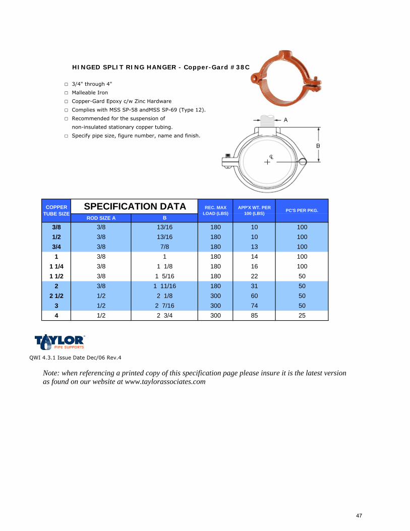
HINGED SPLIT RING HANGER - Copper-Gard #38C
□ 3/4" through 4"
□ Malleable Iron
□ Copper-Gard Epoxy c/w Zinc Hardware
□ Complies with MSS SP-58 andMSS SP-69 (Type 12).
□ Recommended for the suspension of
non-insulated stationary copper tubing.
□ Specify pipe size, figure number, name and finish.
ROD SIZE A
QWI 4.3.1 Issue Date Dec/06 Rev.4
Note: when referencing a printed copy of this specification page please insure it is the latest version as found on our website at www.taylorassociates.com
5050
85
2 1/8 300 60
2 3/4 3002 7/16 74
50180
25
1 5/16 22311 11/16 180
300
50
16 100180100180 14
4
3/8
1 1/41 1/2
2
1/23/41
2 1/2
1/23
SPECIFICATION DATA
1/23/83/83/83/83/8
1/2
1 1/8
100
PC'S PER PKG.
17/8 100
180180
1013
100
COPPER TUBE SIZE
REC. MAX LOAD (LBS)
APP'X WT. PER 100 (LBS)
13/16
B
3/8 13/16 180 103/8
47
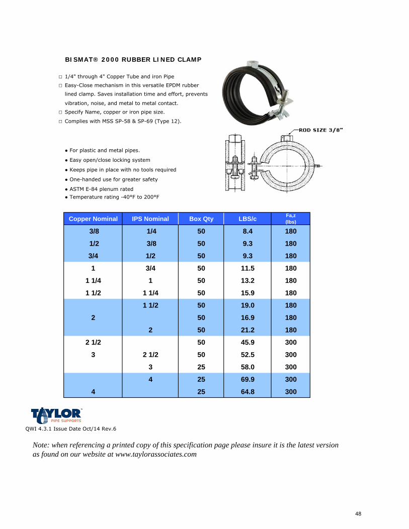
BISMAT® 2000 RUBBER LINED CLAMP
□ 1/4" through 4" Copper Tube and iron Pipe
□ Easy-Close mechanism in this versatile EPDM rubber
lined clamp. Saves installation time and effort, prevents
vibration, noise, and metal to metal contact.
□ Specify Name, copper or iron pipe size.
□ Complies with MSS SP-58 & SP-69 (Type 12).
● For plastic and metal pipes.
● Easy open/close locking system
● Keeps pipe in place with no tools required
● One-handed use for greater safety
● ASTM E-84 plenum rated
● Temperature rating -40°F to 200°F
Copper Nominal IPS Nominal Box Qty LBS/c Fa,z (lbs)
3/8 1/4 50 8.4 180
1/2 3/8 50 9.3 180
3/4 1/2 50 9.3 180
1 3/4 50 11.5 180
1 1/4 1 50 13.2 180
1 1/2 1 1/4 50 15.9 180
1 1/2 50 19.0 180
2 50 16.9 180
2 50 21.2 180
2 1/2 50 45.9 300
3 2 1/2 50 52.5 300
3 25 58.0 300
4 25 69.9 300
4 25 64.8 300
QWI 4.3.1 Issue Date Oct/14 Rev.6
Note: when referencing a printed copy of this specification page please insure it is the latest version as found on our website at www.taylorassociates.com
48
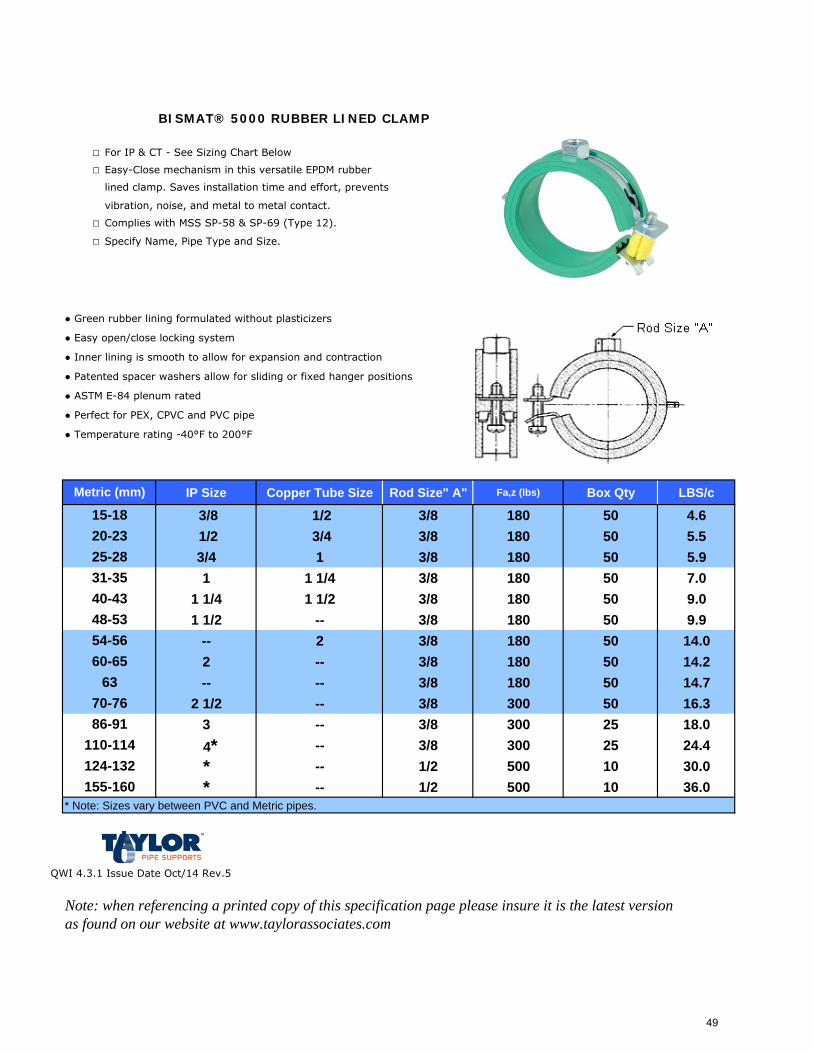
BISMAT® 5000 RUBBER LINED CLAMP
□ For IP & CT - See Sizing Chart Below
□ Easy-Close mechanism in this versatile EPDM rubber
lined clamp. Saves installation time and effort, prevents
vibration, noise, and metal to metal contact.
□ Complies with MSS SP-58 & SP-69 (Type 12).
□ Specify Name, Pipe Type and Size.
● Green rubber lining formulated without plasticizers
● Easy open/close locking system
● Inner lining is smooth to allow for expansion and contraction
● Patented spacer washers allow for sliding or fixed hanger positions
● ASTM E-84 plenum rated
● Perfect for PEX, CPVC and PVC pipe
● Temperature rating -40°F to 200°F
IP Size Copper Tube Size Rod Size" A" Fa,z (lbs) Box Qty LBS/c
3/8 1/2 3/8 180 50 4.61/2 3/4 3/8 180 50 5.53/4 1 3/8 180 50 5.91 1 1/4 3/8 180 50 7.0
1 1/4 1 1/2 3/8 180 50 9.01 1/2 -- 3/8 180 50 9.9
-- 2 3/8 180 50 14.02 -- 3/8 180 50 14.2-- -- 3/8 180 50 14.7
2 1/2 -- 3/8 300 50 16.33 -- 3/8 300 25 18.0
4* -- 3/8 300 25 24.4* -- 1/2 500 10 30.0* -- 1/2 500 10 36.0
QWI 4.3.1 Issue Date Oct/14 Rev.5
Note: when referencing a printed copy of this specification page please insure it is the latest version as found on our website at www.taylorassociates.com
Metric (mm)
15-18
54-56
6370-76
60-65
20-2325-28
40-4348-53
31-35
86-91
124-132155-160
* Note: Sizes vary between PVC and Metric pipes.
110-114
49
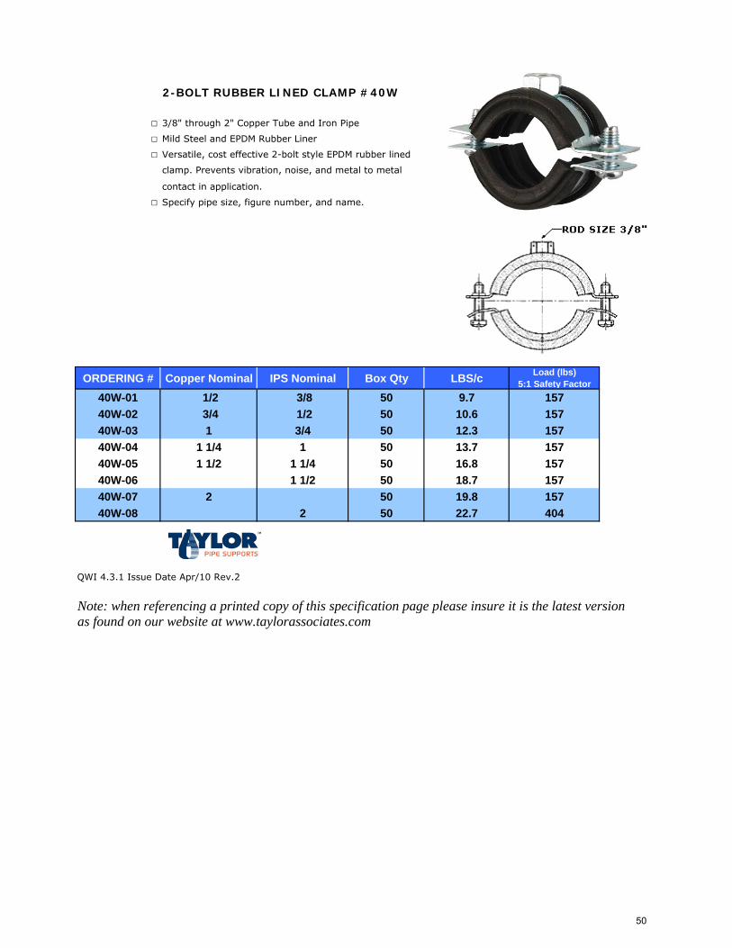
2-BOLT RUBBER LINED CLAMP #40W
□ 3/8" through 2" Copper Tube and Iron Pipe
□ Mild Steel and EPDM Rubber Liner
□ Versatile, cost effective 2-bolt style EPDM rubber lined
clamp. Prevents vibration, noise, and metal to metal
contact in application.
□ Specify pipe size, figure number, and name.
ORDERING # Copper Nominal IPS Nominal Box Qty LBS/c Load (lbs) 5:1 Safety Factor
40W-01 1/2 3/8 50 9.7 15740W-02 3/4 1/2 50 10.6 15740W-03 1 3/4 50 12.3 15740W-04 1 1/4 1 50 13.7 15740W-05 1 1/2 1 1/4 50 16.8 15740W-06 1 1/2 50 18.7 15740W-07 2 50 19.8 15740W-08 2 50 22.7 404
QWI 4.3.1 Issue Date Apr/10 Rev.2
Note: when referencing a printed copy of this specification page please insure it is the latest version as found on our website at www.taylorassociates.com
50
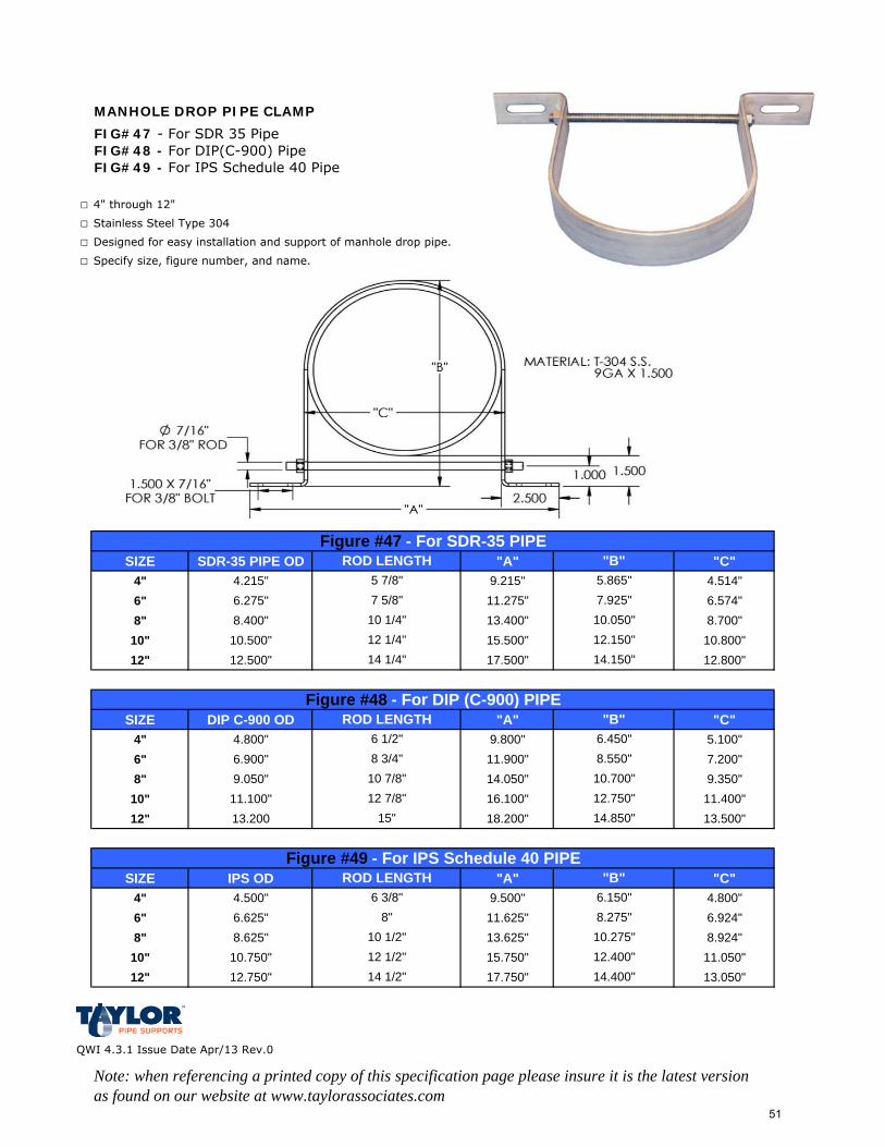
MANHOLE DROP PIPE CLAMP
FIG#47 - For SDR 35 PipeFIG#48 - For DIP(C-900) PipeFIG#49 - For IPS Schedule 40 Pipe
□ 4" through 12"
□ Stainless Steel Type 304
□ Designed for easy installation and support of manhole drop pipe.
□ Specify size, figure number, and name.
SIZE SDR-35 PIPE OD "A" "C"4" 4.215" 9.215" 4.514"6" 6.275" 11.275" 6.574"8" 8.400" 13.400" 8.700"
10" 10.500" 15.500" 10.800"12" 12.500" 17.500" 12.800"
SIZE DIP C-900 OD "A" "C"4" 4.800" 9.800" 5.100"6" 6.900" 11.900" 7.200"8" 9.050" 14.050" 9.350"
10" 11.100" 16.100" 11.400"12" 13.200 18.200" 13.500"
SIZE IPS OD "A" "C"4" 4.500" 9.500" 4.800"6" 6.625" 11.625" 6.924"8" 8.625" 13.625" 8.924"
10" 10.750" 15.750" 11.050"12" 12.750" 17.750" 13.050"
QWI 4.3.1 Issue Date Apr/13 Rev.0
Note: when referencing a printed copy of this specification page please insure it is the latest version as found on our website at www.taylorassociates.com
ROD LENGTH "B"
12 1/4"10 1/4"
12.150"10.050"
ROD LENGTH
7.925"5.865""B"
5 7/8"7 5/8"
Figure #47 - For SDR-35 PIPE
Figure #48 - For DIP (C-900) PIPE
10 7/8" 10.700"8.550"8 3/4"
6 1/2" 6.450"
14.150"14 1/4"
12 7/8" 12.750"15" 14.850"
Figure #49 - For IPS Schedule 40 PIPEROD LENGTH "B"
6 3/8" 6.150"8" 8.275"
10 1/2" 10.275"12 1/2" 12.400"14 1/2" 14.400"
51
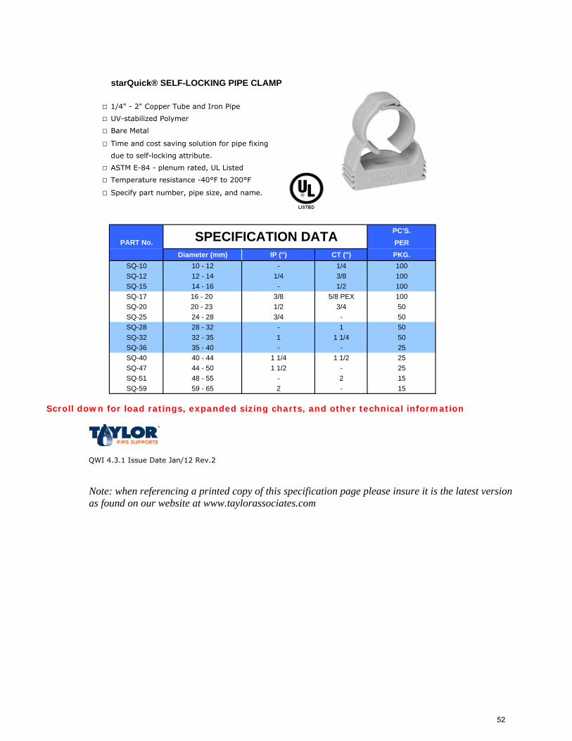
starQuick® SELF-LOCKING PIPE CLAMP
□ 1/4" - 2" Copper Tube and Iron Pipe
□ UV-stabilized Polymer
□ Bare Metal
□ Time and cost saving solution for pipe fixing
due to self-locking attribute.
□ ASTM E-84 - plenum rated, UL Listed
□ Temperature resistance -40°F to 200°F
□ Specify part number, pipe size, and name.
PC'S.PER
Diameter (mm) IP ('') CT (") PKG.SQ-10 10 - 12 - 1/4 100SQ-12 12 - 14 1/4 3/8 100SQ-15 14 - 16 - 1/2 100SQ-17 16 - 20 3/8 5/8 PEX 100SQ-20 20 - 23 1/2 3/4 50SQ-25 24 - 28 3/4 - 50SQ-28 28 - 32 - 1 50SQ-32 32 - 35 1 1 1/4 50SQ-36 35 - 40 - - 25SQ-40 40 - 44 1 1/4 1 1/2 25SQ-47 44 - 50 1 1/2 - 25SQ-51 48 - 55 - 2 15SQ-59 59 - 65 2 - 15
QWI 4.3.1 Issue Date Jan/12 Rev.2
Note: when referencing a printed copy of this specification page please insure it is the latest version as found on our website at www.taylorassociates.com
PART No. SPECIFICATION DATA
Scroll down for load ratings, expanded sizing charts, and other technical information
52
www.raywal-usa.com
Product Specification starQuick® System 25/50 Plenum Rated
Prod
uct S
peci
ficat
ion
star
Quic
k® Ple
num
Rat
ing
- 12
/201
0 -
- Su
bjec
t to
mod
ifica
tions
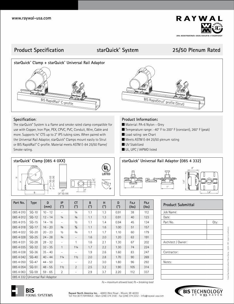
Specification:The starQuick® System is a flame and smoke rated clamp compatible for use with Copper, Iron Pipe, PEX, CPVC, PVC, Conduit, Wire, Cable and more. Supports ¼” CTS up to 2” IPS tubing sizes. When paired with the Universal Rail Adaptor, starQuick® Clamps mount easily to Strut or BIS RapidRail® C-profile. Material meets ASTM E-84 25/50 Flame/Smoke rating.
Product Information: Material: PA-6 Nylon - Grey Temperature range: -40° F to 200° F (constant), 260° F (peak) Load rating: see Chart Meets ASTM E-84 25/50 plenum rating UV Stabilized UL, UPC / IAPMO listed
Part No. Type D(mm)
IP(“)
CT(“)
B(“)
H(“)
D(“)
Fa,z(lbs)
Fb,z(lbs)
085 4 010 SQ-10 10 - 12 - ¼ 1.1 1.3 0.91 38 112085 4 012 SQ-12 12 - 14 ¼ � 1.1 1.3 0.91 40 123
085 4 015 SQ-15 14 - 16 - ½ 1.1 1.4 0.94 45 134
085 4 018 SQ-17 16 - 20 � ⅝ 1.1 1.6 1.00 51 157
085 4 022 SQ-20 20 - 23 ½ ¾ 1.1 1.7 1.10 60 179
085 4 028 SQ-25 24 - 28 ¾ - 1.6 2.0 1.20 63 191
085 4 031 SQ-28 28 - 32 - 1 1.6 2.1 1.30 67 202
085 4 035 SQ-32 32 - 35 1 1¼ 1.7 2.2 1.30 74 224
085 4 038 SQ-36 35 - 40 - - 1.9 2.6 1.60 83 247085 4 042 SQ-40 40 - 44 1¼ 1½ 2.0 2.8 1.70 90 269085 4 050 SQ-47 44 - 50 - - 2.2 3.0 1.80 96 292
085 4 054 SQ-51 48 - 55 1½ 2 2.5 3.2 1.90 105 314085 4 063 SQ-59 59 - 65 2 - 2.9 3.7 2.20 112 337
085 4 332 Universal Rail Adaptor
Product Submittal
Job Name:
Date:
Part No. Qty:
Architect / Owner:
Contractor:
Notes:
Fa = maximum allowed load, Fb = breaking load
D
h
H
.4” (
<= S
Q-32
).5
” (>=
SQ-
36)
B.67”
(.8” SQ-59)
.18”
.4”
BIS RapidRail® C-profileBIS RapidStrut® profile (Strut)
starQuick® Clamp (085 4 0XX)
.8”
1.4”
1.4”
1.4” 1”
starQuick® Universal Rail Adaptor (085 4 332)
starQuick® Clamp + starQuick® Universal Rail Adaptor
Raywal North America Inc. - 48893 West Road - Wixom, MI 48393Toll free (877) RAYWAL9 - Main (248) 374 3100 - Fax (248) 374 3232 - [email protected]
53
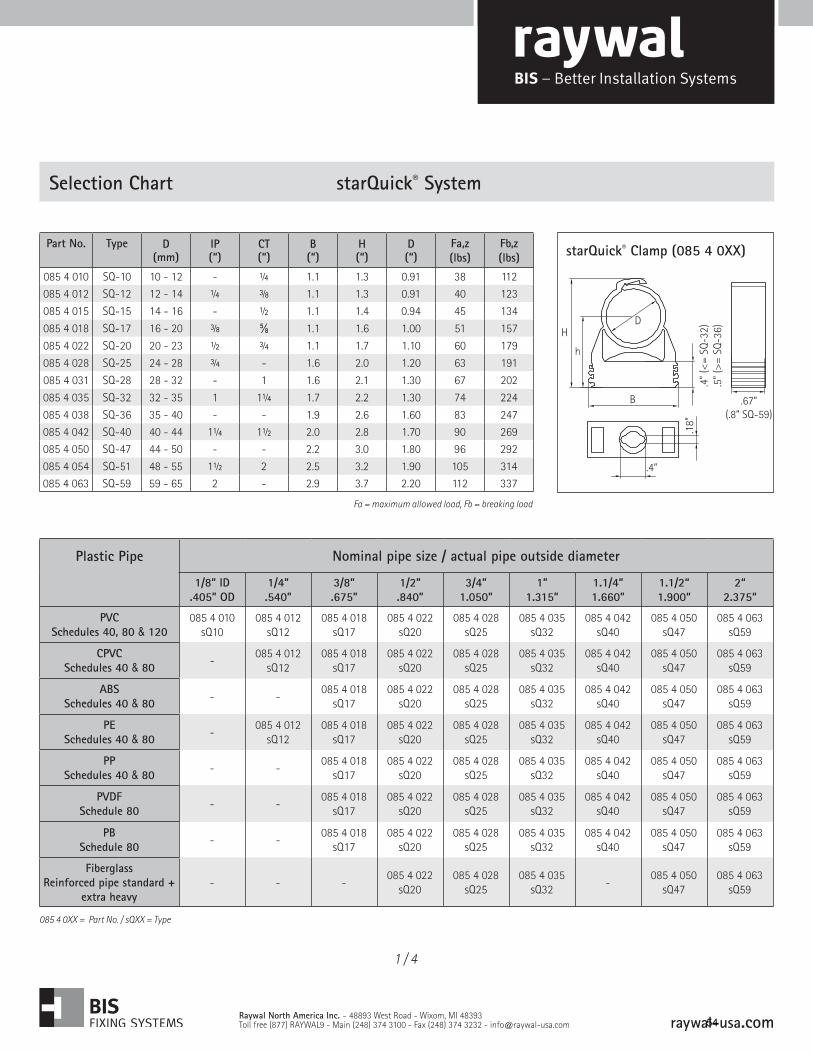
Selection Chart starQuick® System
Raywal North America Inc. - 48893 West Road - Wixom, MI 48393Toll free (877) RAYWAL9 - Main (248) 374 3100 - Fax (248) 374 3232 - [email protected]
Part No. Type D(mm)
IP(“)
CT(“)
B(“)
H(“)
D(“)
Fa,z(lbs)
Fb,z(lbs)
085 4 010 SQ-10 10 - 12 - ¼ 1.1 1.3 0.91 38 112085 4 012 SQ-12 12 - 14 ¼ � 1.1 1.3 0.91 40 123
085 4 015 SQ-15 14 - 16 - ½ 1.1 1.4 0.94 45 134
085 4 018 SQ-17 16 - 20 � ⅝ 1.1 1.6 1.00 51 157
085 4 022 SQ-20 20 - 23 ½ ¾ 1.1 1.7 1.10 60 179
085 4 028 SQ-25 24 - 28 ¾ - 1.6 2.0 1.20 63 191
085 4 031 SQ-28 28 - 32 - 1 1.6 2.1 1.30 67 202
085 4 035 SQ-32 32 - 35 1 1¼ 1.7 2.2 1.30 74 224
085 4 038 SQ-36 35 - 40 - - 1.9 2.6 1.60 83 247085 4 042 SQ-40 40 - 44 1¼ 1½ 2.0 2.8 1.70 90 269085 4 050 SQ-47 44 - 50 - - 2.2 3.0 1.80 96 292
085 4 054 SQ-51 48 - 55 1½ 2 2.5 3.2 1.90 105 314085 4 063 SQ-59 59 - 65 2 - 2.9 3.7 2.20 112 337
Fa = maximum allowed load, Fb = breaking load
D
h
H
.4” (
<= S
Q-32
).5
” (>=
SQ-
36)
B .67”(.8” SQ-59)
.18”
.4”
starQuick® Clamp (085 4 0XX)
Plastic Pipe Nominal pipe size / actual pipe outside diameter
1/8” ID.405” OD
1/4”.540”
3/8”.675”
1/2”.840”
3/4”1.050”
1”1.315”
1.1/4”1.660”
1.1/2“1.900“
2“2.375“
PVCSchedules 40, 80 & 120
085 4 010 sQ10
085 4 012 sQ12
085 4 018 sQ17
085 4 022 sQ20
085 4 028 sQ25
085 4 035sQ32
085 4 042sQ40
085 4 050sQ47
085 4 063sQ59
CPVCSchedules 40 & 80 -
085 4 012 sQ12
085 4 018 sQ17
085 4 022 sQ20
085 4 028 sQ25
085 4 035sQ32
085 4 042sQ40
085 4 050sQ47
085 4 063sQ59
ABSSchedules 40 & 80 - -
085 4 018 sQ17
085 4 022 sQ20
085 4 028 sQ25
085 4 035sQ32
085 4 042sQ40
085 4 050sQ47
085 4 063sQ59
PESchedules 40 & 80 -
085 4 012 sQ12
085 4 018 sQ17
085 4 022 sQ20
085 4 028 sQ25
085 4 035sQ32
085 4 042sQ40
085 4 050sQ47
085 4 063sQ59
PPSchedules 40 & 80 - -
085 4 018 sQ17
085 4 022 sQ20
085 4 028 sQ25
085 4 035sQ32
085 4 042sQ40
085 4 050sQ47
085 4 063sQ59
PVDFSchedule 80 - -
085 4 018 sQ17
085 4 022 sQ20
085 4 028 sQ25
085 4 035sQ32
085 4 042sQ40
085 4 050sQ47
085 4 063sQ59
PBSchedule 80 - -
085 4 018 sQ17
085 4 022 sQ20
085 4 028 sQ25
085 4 035sQ32
085 4 042sQ40
085 4 050sQ47
085 4 063sQ59
FiberglassReinforced pipe standard +
extra heavy- - -
085 4 022 sQ20
085 4 028 sQ25
085 4 035sQ32
-085 4 050
sQ47085 4 063
sQ59
085 4 0XX = Part No. / sQXX = Type
1 / 4
raywal-usa.com 54
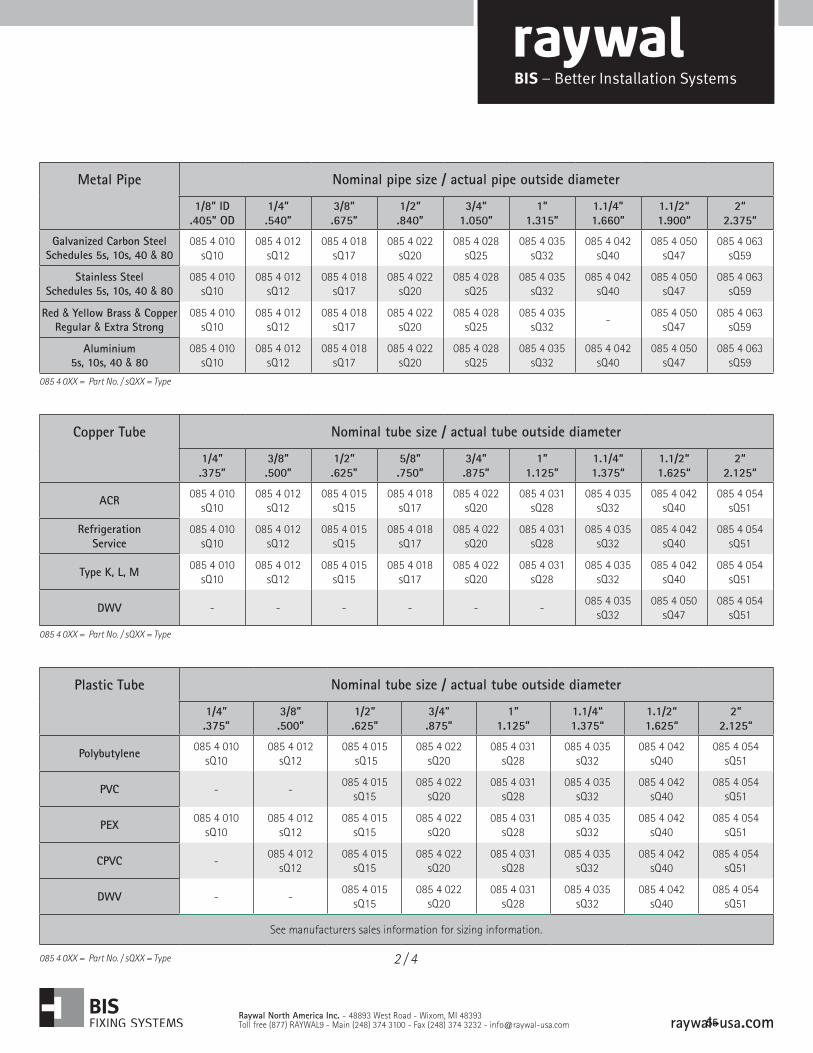
Metal Pipe Nominal pipe size / actual pipe outside diameter
1/8” ID.405” OD
1/4”.540”
3/8”.675”
1/2”.840”
3/4”1.050”
1”1.315”
1.1/4”1.660”
1.1/2“1.900“
2“2.375“
Galvanized Carbon SteelSchedules 5s, 10s, 40 & 80
085 4 010 sQ10
085 4 012 sQ12
085 4 018 sQ17
085 4 022 sQ20
085 4 028 sQ25
085 4 035sQ32
085 4 042sQ40
085 4 050sQ47
085 4 063sQ59
Stainless SteelSchedules 5s, 10s, 40 & 80
085 4 010 sQ10
085 4 012 sQ12
085 4 018 sQ17
085 4 022 sQ20
085 4 028 sQ25
085 4 035sQ32
085 4 042sQ40
085 4 050sQ47
085 4 063sQ59
Red & Yellow Brass & CopperRegular & Extra Strong
085 4 010 sQ10
085 4 012 sQ12
085 4 018 sQ17
085 4 022 sQ20
085 4 028 sQ25
085 4 035sQ32
-085 4 050
sQ47085 4 063
sQ59
Aluminium5s, 10s, 40 & 80
085 4 010 sQ10
085 4 012 sQ12
085 4 018 sQ17
085 4 022 sQ20
085 4 028 sQ25
085 4 035sQ32
085 4 042sQ40
085 4 050sQ47
085 4 063sQ59
085 4 0XX = Part No. / sQXX = Type
Copper Tube Nominal tube size / actual tube outside diameter
1/4”.375”
3/8”.500”
1/2”.625”
5/8”.750”
3/4”.875”
1”1.125”
1.1/4“1.375“
1.1/2“1.625“
2“2.125“
ACR 085 4 010 sQ10
085 4 012 sQ12
085 4 015 sQ15
085 4 018 sQ17
085 4 022 sQ20
085 4 031 sQ28
085 4 035sQ32
085 4 042sQ40
085 4 054 sQ51
Refrigeration Service
085 4 010 sQ10
085 4 012 sQ12
085 4 015 sQ15
085 4 018 sQ17
085 4 022 sQ20
085 4 031 sQ28
085 4 035sQ32
085 4 042sQ40
085 4 054 sQ51
Type K, L, M 085 4 010 sQ10
085 4 012 sQ12
085 4 015 sQ15
085 4 018 sQ17
085 4 022 sQ20
085 4 031 sQ28
085 4 035sQ32
085 4 042sQ40
085 4 054 sQ51
DWV - - - - - -085 4 035
sQ32085 4 050
sQ47085 4 054
sQ51
085 4 0XX = Part No. / sQXX = Type
Plastic Tube Nominal tube size / actual tube outside diameter
1/4”.375”
3/8”.500”
1/2”.625”
3/4”.875”
1”1.125”
1.1/4“1.375“
1.1/2“1.625“
2“2.125“
Polybutylene 085 4 010 sQ10
085 4 012 sQ12
085 4 015 sQ15
085 4 022sQ20
085 4 031sQ28
085 4 035sQ32
085 4 042sQ40
085 4 054 sQ51
PVC - -085 4 015
sQ15085 4 022
sQ20085 4 031
sQ28085 4 035
sQ32085 4 042
sQ40085 4 054
sQ51
PEX 085 4 010 sQ10
085 4 012 sQ12
085 4 015sQ15
085 4 022 sQ20
085 4 031sQ28
085 4 035sQ32
085 4 042sQ40
085 4 054 sQ51
CPVC -085 4 012
sQ12085 4 015
sQ15085 4 022
sQ20085 4 031
sQ28085 4 035
sQ32085 4 042
sQ40085 4 054
sQ51
DWV - -085 4 015
sQ15085 4 022
sQ20085 4 031
sQ28085 4 035
sQ32085 4 042
sQ40085 4 054
sQ51
See manufacturers sales information for sizing information.
085 4 0XX = Part No. / sQXX = Type 2 / 4
Raywal North America Inc. - 48893 West Road - Wixom, MI 48393Toll free (877) RAYWAL9 - Main (248) 374 3100 - Fax (248) 374 3232 - [email protected] raywal-usa.com
55
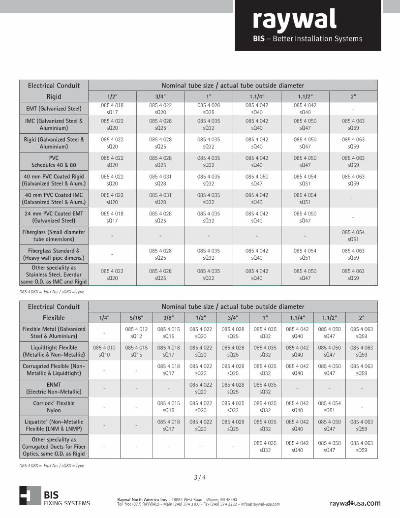
085 4 0XX = Part No. / sQXX = Type
Electrical Conduit Nominal tube size / actual tube outside diameter
Flexible 1/4” 5/16“ 3/8” 1/2” 3/4” 1” 1.1/4“ 1.1/2“ 2“
Flexible Metal (Galvanized Steel & Aluminium) -
085 4 012 sQ12
085 4 015 sQ15
085 4 022 sQ20
085 4 028sQ25
085 4 035sQ32
085 4 042sQ40
085 4 050sQ47
085 4 063sQ59
Liquidtight Flexible(Metallic & Non-Metallic)
085 4 010 sQ10
085 4 015 sQ15
085 4 018 sQ17
085 4 022 sQ20
085 4 028sQ25
085 4 035sQ32
085 4 042sQ40
085 4 050sQ47
085 4 063sQ59
Corrugated Flexible (Non-Metallic & Liquidtight) - -
085 4 018 sQ17
085 4 022 sQ20
085 4 028sQ25
085 4 035sQ32
085 4 042sQ40
085 4 050sQ47
085 4 063sQ59
ENMT(Electric Non-Metallic) - - -
085 4 022 sQ20
085 4 028sQ25
085 4 035sQ32
- - -
Corrlock® FlexibleNylon - -
085 4 015 sQ15
085 4 022 sQ20
085 4 035sQ32
085 4 035sQ32
085 4 042sQ40
085 4 054 sQ51
-
Liquatite® (Non-Metallic Flexible (LNM & LNMP) - -
085 4 018 sQ17
085 4 022 sQ20
085 4 028sQ25
085 4 035sQ32
085 4 042sQ40
085 4 050sQ47
085 4 063sQ59
Other speciality as Corrugated Ducts for Fiber Optics, same O.D. as Rigid
- - - - -085 4 035
sQ32085 4 042
sQ40085 4 050
sQ47085 4 063
sQ59
Electrical Conduit Nominal tube size / actual tube outside diameter
Rigid 1/2” 3/4” 1” 1.1/4“ 1.1/2“ 2“
EMT (Galvanized Steel) 085 4 018 sQ17
085 4 022 sQ20
085 4 028sQ25
085 4 042sQ40
085 4 042sQ40
-
IMC (Galvanized Steel & Aluminium)
085 4 022sQ20
085 4 028sQ25
085 4 035sQ32
085 4 042sQ40
085 4 050sQ47
085 4 063sQ59
Rigid (Galvanized Steel & Aluminium)
085 4 022sQ20
085 4 028sQ25
085 4 035sQ32
085 4 042sQ40
085 4 050sQ47
085 4 063sQ59
PVCSchedules 40 & 80
085 4 022sQ20
085 4 028sQ25
085 4 035sQ32
085 4 042sQ40
085 4 050sQ47
085 4 063sQ59
40 mm PVC Coated Rigid(Galvanized Steel & Alum.)
085 4 022sQ20
085 4 031sQ28
085 4 035sQ32
085 4 050sQ47
085 4 054 sQ51
085 4 063sQ59
40 mm PVC Coated IMC(Galvanized Steel & Alum.)
085 4 022sQ20
085 4 031sQ28
085 4 035sQ32
085 4 042sQ40
085 4 054 sQ51
-
24 mm PVC Coated EMT(Galvanized Steel)
085 4 018sQ17
085 4 028sQ25
085 4 035sQ32
085 4 042sQ40
085 4 050sQ47
-
Fiberglass (Small diameter tube dimensions) - - - - -
085 4 054 sQ51
Fiberglass Standard & (Heavy wall pipe dimens.)
-085 4 028
sQ25085 4 035
sQ32085 4 042
sQ40085 4 054
sQ51085 4 063
sQ59
Other speciality as Stainless Steel, Everdur
same O.D. as IMC and Rigid
085 4 022sQ20
085 4 028sQ25
085 4 035sQ32
085 4 042sQ40
085 4 050sQ47
085 4 063sQ59
085 4 0XX = Part No. / sQXX = Type
3 / 4
Raywal North America Inc. - 48893 West Road - Wixom, MI 48393Toll free (877) RAYWAL9 - Main (248) 374 3100 - Fax (248) 374 3232 - [email protected] raywal-usa.com
56
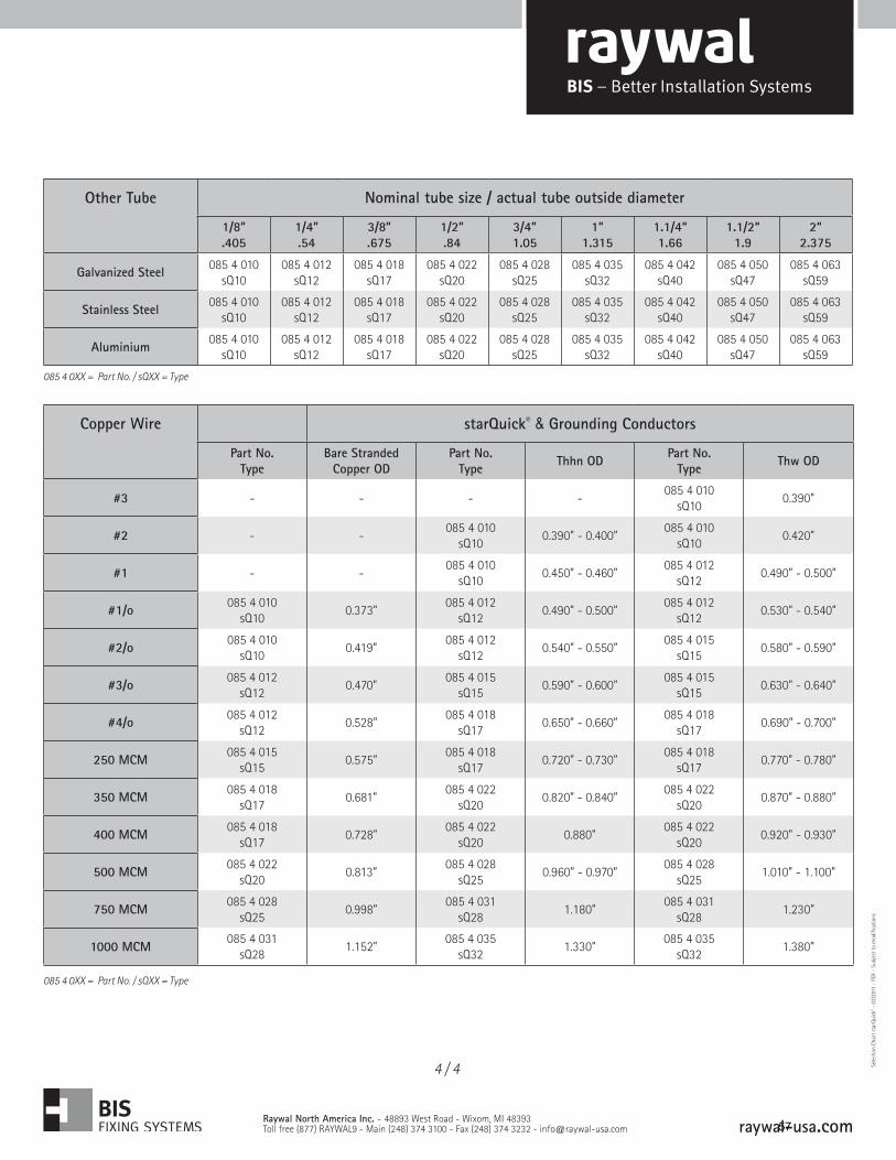
Copper Wire starQuick® & Grounding Conductors
Part No.Type
Bare Stranded Copper OD
Part No.Type Thhn OD Part No.
Type Thw OD
#3 - - - -085 4 010
sQ100.390”
#2 - -085 4 010
sQ100.390” - 0.400”
085 4 010 sQ10
0.420”
#1 - -085 4 010
sQ100.450” - 0.460”
085 4 012 sQ12
0.490” - 0.500”
#1/o 085 4 010 sQ10
0.373”085 4 012
sQ120.490” - 0.500”
085 4 012 sQ12
0.530” - 0.540”
#2/o 085 4 010sQ10
0.419”085 4 012
sQ120.540” - 0.550”
085 4 015 sQ15
0.580” - 0.590”
#3/o 085 4 012sQ12
0.470”085 4 015
sQ150.590” - 0.600”
085 4 015 sQ15
0.630” - 0.640”
#4/o 085 4 012sQ12
0.528”085 4 018
sQ170.650” - 0.660”
085 4 018 sQ17
0.690” - 0.700”
250 MCM 085 4 015 sQ15
0.575”085 4 018
sQ170.720” - 0.730”
085 4 018 sQ17
0.770” - 0.780”
350 MCM 085 4 018 sQ17
0.681”085 4 022
sQ200.820” - 0.840”
085 4 022 sQ20
0.870” - 0.880”
400 MCM 085 4 018 sQ17
0.728”085 4 022
sQ200.880”
085 4 022 sQ20
0.920” - 0.930”
500 MCM 085 4 022 sQ20
0.813”085 4 028
sQ250.960” - 0.970”
085 4 028sQ25
1.010” - 1.100”
750 MCM 085 4 028sQ25
0.998”085 4 031
sQ281.180”
085 4 031sQ28
1.230”
1000 MCM 085 4 031sQ28
1.152”085 4 035
sQ321.330”
085 4 035sQ32
1.380”
Other Tube Nominal tube size / actual tube outside diameter
1/8”.405
1/4”.54
3/8”.675
1/2”.84
3/4”1.05
1”1.315
1.1/4“1.66
1.1/2“ 1.9
2“2.375
Galvanized Steel 085 4 010 sQ10
085 4 012 sQ12
085 4 018 sQ17
085 4 022 sQ20
085 4 028 sQ25
085 4 035sQ32
085 4 042sQ40
085 4 050sQ47
085 4 063sQ59
Stainless Steel 085 4 010 sQ10
085 4 012 sQ12
085 4 018 sQ17
085 4 022 sQ20
085 4 028 sQ25
085 4 035sQ32
085 4 042sQ40
085 4 050sQ47
085 4 063sQ59
Aluminium 085 4 010 sQ10
085 4 012 sQ12
085 4 018 sQ17
085 4 022 sQ20
085 4 028 sQ25
085 4 035sQ32
085 4 042sQ40
085 4 050sQ47
085 4 063sQ59
085 4 0XX = Part No. / sQXX = Type
4 / 4
Raywal North America Inc. - 48893 West Road - Wixom, MI 48393Toll free (877) RAYWAL9 - Main (248) 374 3100 - Fax (248) 374 3232 - [email protected]
085 4 0XX = Part No. / sQXX = Type
Sele
ctio
n Ch
art s
tarQ
uick
® - 0
3/20
11 -
- S
ubje
ct to
mod
ifica
tions
raywal-usa.com 57
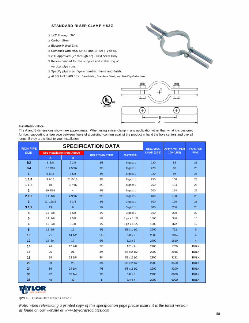
STANDARD RISER CLAMP #82Z
□ 1/2" through 36"
□ Carbon Steel
□ Electro-Plated Zinc
□ Complies with MSS SP-58 and SP-69 (Type 8).
□ cUL Approved (2" through 8") - Mild Steel Only
□ Recommended for the support and stabilizing of
vertical pipe runs.
□ Specify pipe size, figure number, name and finish.
□ ALSO AVAILABLE IN: Bare Metal, Stainless Steel, and Hot-Dip Galvanized
Installation Note:The A and B dimensions shown are approximate. When using a riser clamp in any application other than what it is designed for (i.e.. supporting a riser pipe between floors of a building) confirm against the product in hand the hole centers and overall length if they are critical to your installation.
QWI 4.3.1 Issue Date May/13 Rev.19
Note: when referencing a printed copy of this specification page please insure it is the latest version as found on our website at www.taylorassociates.com
3/4 x 4 2900 9000 BULK36 48 42 1
5/8 x 3 2900 6000 BULK30 42 35 1/4 7/8
5/8 x 2 1/2 2900 4200 BULK24 36 29 1/4 7/8
94
3/8
3/8
BOLT DIAMETER MATERIALSee Installation Note Above
1037216003 ga x 1 1/21/2
34015003 ga x 1 1/2 10
3 ga x 11/2 20220750
1/2
1/2 252066003 ga x 1
254003 ga x 1
3/8 170 255003 ga x 1
3/8 1148 ga x 1
3/8 160
251048 ga x 1
300 25
2 15/16 8 ga x 13/8
2503/8
BULK3/420 30 25 5/8 x 2 1/2 2900 3550
BULK3/418 28 23 1/8 5/8 x 2 1/2 2900 3191
BULK3/416 26 21 5/8 x 2 1/2 2900 2916
1/2 x 2 2700 1700 BULK5/814 24 17 7/8
1/2 x 2 2700 1610 45/812 22 3/4 17
3/8 x 2 2500 1094 45/810 21 14 1/2
3/8 x 1 1/2 2500 722 55/88 18 5/8 12
6 15 3/8 8 7/8
5 14 1/8 7 5/8
4 13 5/8 6 5/8
SPECIFICATION DATA
8 ga x 1
8 ga x 1
8 ga x 1
4 9/16
A
1 1/4
13 6
11 13/16 5 1/4
11 1/8
25
100 25
2202 5/8
3 7/16
4
2509 7/16
25
8 13/16 2 5/16 25
220
220 923/8
2 1/8 88
3
3 1/2
8 5/8
9 1/16
10
10 9/16
1 1/2
2
2 1/2
1/2
3/4
1
B
IRON PIPE SIZE
REC. MAX. LOAD (LBS)
APP'X WT. PER 100 (LBS)
PC'S PER PKG.
58
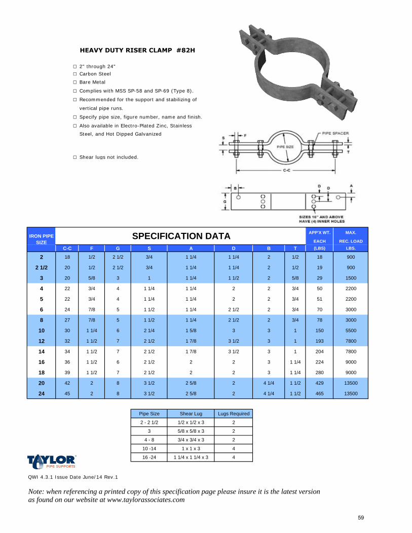
HEAVY DUTY RISER CLAMP #82H
□ 2" through 24"
□ Carbon Steel
□ Bare Metal
□ Complies with MSS SP-58 and SP-69 (Type 8).
□ Recommended for the support and stabilizing of
vertical pipe runs.
□ Specify pipe size, figure number, name and finish.
□ Also available in Electro-Plated Zinc, Stainless
Steel, and Hot Dipped Galvanized
□ Shear lugs not included.
APP'X WT. MAX.
EACH REC. LOADC-C F G S A D B T (LBS) LBS.
2 18 1/2 2 1/2 3/4 1 1/4 1 1/4 2 1/2 18 900
2 1/2 20 1/2 2 1/2 3/4 1 1/4 1 1/4 2 1/2 19 900
3 20 5/8 3 1 1 1/4 1 1/2 2 5/8 29 1500
4 22 3/4 4 1 1/4 1 1/4 2 2 3/4 50 2200
5 22 3/4 4 1 1/4 1 1/4 2 2 3/4 51 2200
6 24 7/8 5 1 1/2 1 1/4 2 1/2 2 3/4 70 3000
8 27 7/8 5 1 1/2 1 1/4 2 1/2 2 3/4 78 3000
10 30 1 1/4 6 2 1/4 1 5/8 3 3 1 150 5500
12 32 1 1/2 7 2 1/2 1 7/8 3 1/2 3 1 193 7800
14 34 1 1/2 7 2 1/2 1 7/8 3 1/2 3 1 204 7800
16 36 1 1/2 6 2 1/2 2 2 3 1 1/4 224 9000
18 39 1 1/2 7 2 1/2 2 2 3 1 1/4 280 9000
20 42 2 8 3 1/2 2 5/8 2 4 1/4 1 1/2 429 13500
24 45 2 8 3 1/2 2 5/8 2 4 1/4 1 1/2 465 13500
Pipe Size Shear Lug Lugs Required
2 - 2 1/2 1/2 x 1/2 x 3 2
3 5/8 x 5/8 x 3 2
4 - 8 3/4 x 3/4 x 3 2
10 -14 1 x 1 x 3 4
16 -24 1 1/4 x 1 1/4 x 3 4
QWI 4.3.1 Issue Date June/14 Rev.1
Note: when referencing a printed copy of this specification page please insure it is the latest version as found on our website at www.taylorassociates.com
SPECIFICATION DATAIRON PIPE SIZE
59
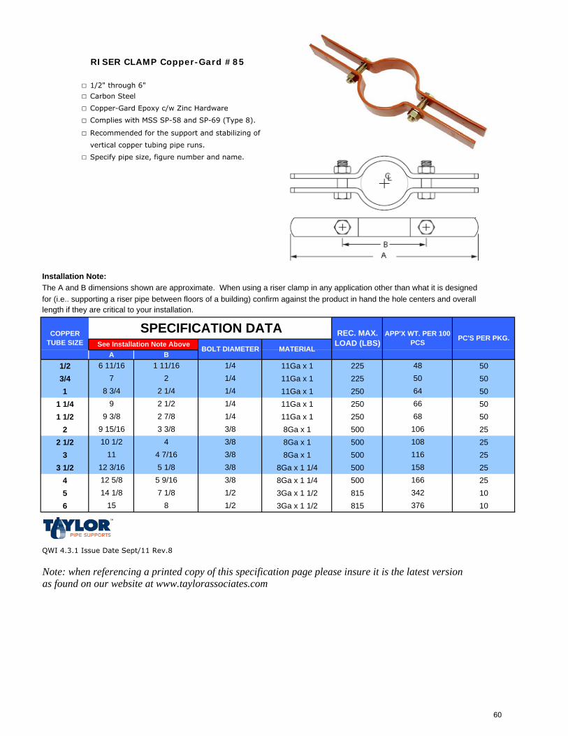
RISER CLAMP Copper-Gard #85
□ 1/2" through 6"
□ Carbon Steel
□ Copper-Gard Epoxy c/w Zinc Hardware
□ Complies with MSS SP-58 and SP-69 (Type 8).
□ Recommended for the support and stabilizing of
vertical copper tubing pipe runs.
□ Specify pipe size, figure number and name.
Installation Note:The A and B dimensions shown are approximate. When using a riser clamp in any application other than what it is designed for (i.e.. supporting a riser pipe between floors of a building) confirm against the product in hand the hole centers and overall length if they are critical to your installation.
1/2 11Ga x 1 225 503/4 11Ga x 1 225 501 11Ga x 1 250 50
1 1/4 11Ga x 1 250 501 1/2 11Ga x 1 250 50
2 8Ga x 1 500 252 1/2 8Ga x 1 500 25
3 8Ga x 1 500 253 1/2 8Ga x 1 1/4 500 25
4 8Ga x 1 1/4 500 255 3Ga x 1 1/2 815 106 3Ga x 1 1/2 815 10
QWI 4.3.1 Issue Date Sept/11 Rev.8
Note: when referencing a printed copy of this specification page please insure it is the latest version as found on our website at www.taylorassociates.com
1/42 1/2
9 15/164
98 3/4 2 1/4
1/41/4
7 2
COPPER TUBE SIZE
6 11/16 1 11/16 1/4
SPECIFICATION DATABOLT DIAMETER MATERIAL
68
A B
9 3/8 2 7/8
48
661/46450
10610 1/2
3/8
3 3/8 3/8108
11 4 7/16 1163/8
15812 3/16 3/85 1/816612 5/8 5 9/16 3/834214 1/8 7 1/8 1/237615 8 1/2
REC. MAX. LOAD (LBS)
APP'X WT. PER 100 PCS PC'S PER PKG.
See Installation Note Above
60
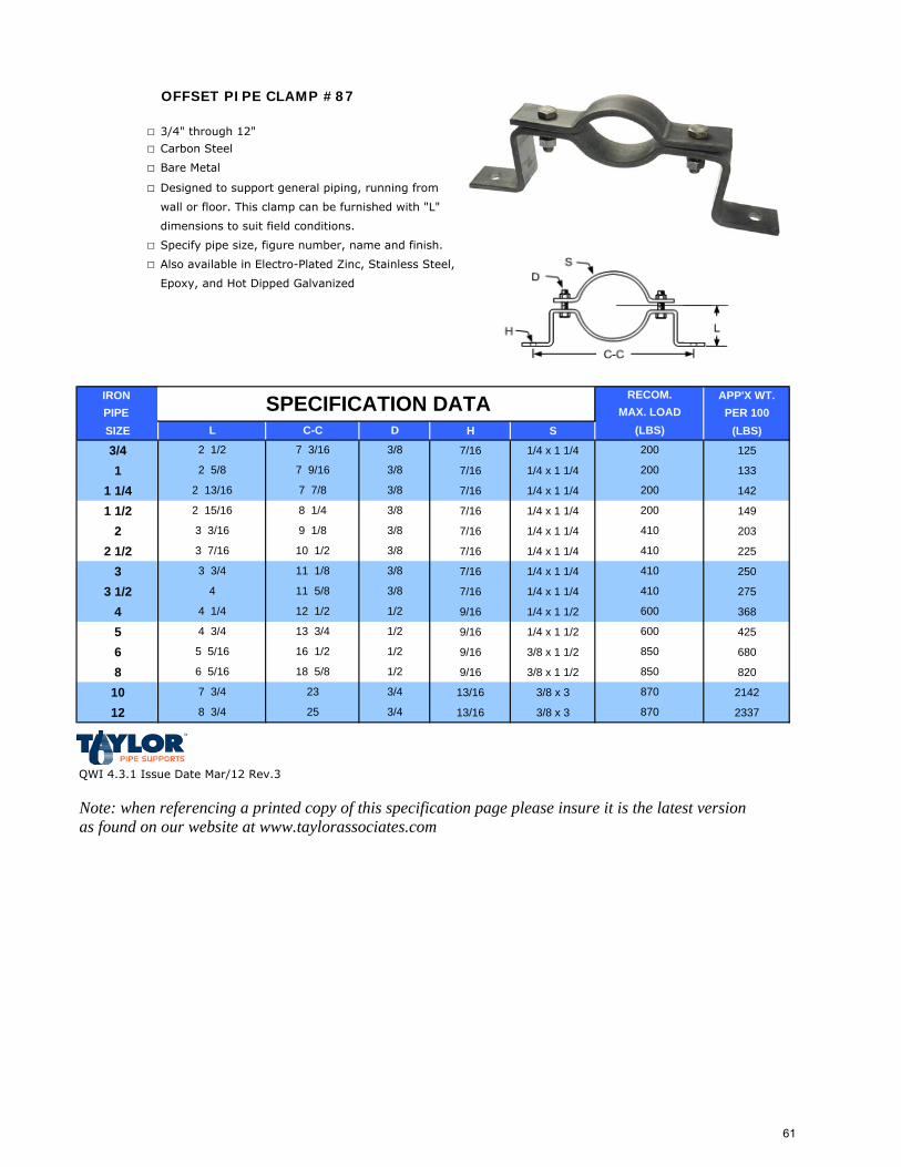
OFFSET PIPE CLAMP #87
□ 3/4" through 12"
□ Carbon Steel
□ Bare Metal
□ Designed to support general piping, running from
wall or floor. This clamp can be furnished with "L"
dimensions to suit field conditions.
□ Specify pipe size, figure number, name and finish.
□ Also available in Electro-Plated Zinc, Stainless Steel,
Epoxy, and Hot Dipped Galvanized
IRON APP'X WT.PIPE PER 100SIZE H S (LBS)
3/4 7/16 1/4 x 1 1/4 125
1 7/16 1/4 x 1 1/4 133
1 1/4 7/16 1/4 x 1 1/4 142
1 1/2 7/16 1/4 x 1 1/4 149
2 7/16 1/4 x 1 1/4 203
2 1/2 7/16 1/4 x 1 1/4 225
3 7/16 1/4 x 1 1/4 250
3 1/2 7/16 1/4 x 1 1/4 275
4 9/16 1/4 x 1 1/2 368
5 9/16 1/4 x 1 1/2 425
6 9/16 3/8 x 1 1/2 680
8 9/16 3/8 x 1 1/2 820
10 13/16 3/8 x 3 2142
12 13/16 3/8 x 3 2337
QWI 4.3.1 Issue Date Mar/12 Rev.3
Note: when referencing a printed copy of this specification page please insure it is the latest version as found on our website at www.taylorassociates.com
200
3/8
3/8
2 1/2
RECOM.MAX. LOAD
(LBS)D
9 1/8
10 1/2
2 5/8 7 9/16
2 13/16
3 3/16
3 7/16
2 15/16 8 1/4
7 7/8
SPECIFICATION DATAL C-C
7 3/16
4 3/4 13 3/4
11 1/8
4 1/4 12 1/2
4 11 5/8
3 3/4
6 5/16 18 5/8
5 5/16 16 1/2
8703/47 3/4 23
8 3/4 25 3/4 870
3/8 410
3/8
3/8 410
200
600
600
3/8 410
410
3/8
200
1/2
850
200
1/2
1/2
3/8
850
1/2
61
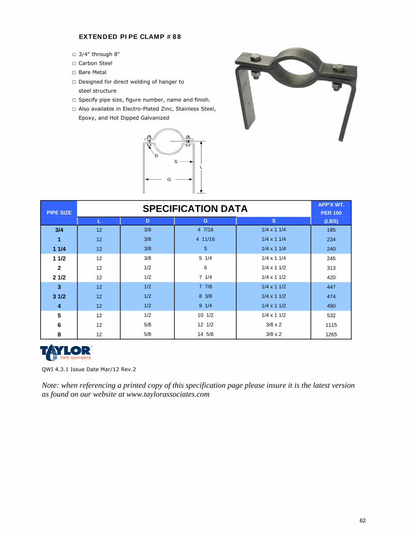
EXTENDED PIPE CLAMP #88
□ 3/4" through 8"
□ Carbon Steel
□ Bare Metal
□ Designed for direct welding of hanger to
steel structure
□ Specify pipe size, figure number, name and finish.
□ Also available in Electro-Plated Zinc, Stainless Steel,
Epoxy, and Hot Dipped Galvanized
APP'X WT.PER 100
L (LBS)
3/4 12 185
1 12 234
1 1/4 12 240
1 1/2 12 245
2 12 313
2 1/2 12 420
3 12 447
3 1/2 12 474
4 12 490
5 12 532
6 12 1115
8 12 1265
QWI 4.3.1 Issue Date Mar/12 Rev.2
Note: when referencing a printed copy of this specification page please insure it is the latest version as found on our website at www.taylorassociates.com
1/4 x 1 1/2
3/8
1/2
1/2
1/2
1/2 10 1/2
9 1/4 1/4 x 1 1/2
7 7/8
5/8 14 5/8 3/8 x 2
3/8 x 25/8 12 1/2
1/4 x 1 1/2
7 1/4 1/4 x 1 1/2
1/2 8 3/8 1/4 x 1 1/2
3/8
PIPE SIZED
1/2
SPECIFICATION DATA
6
5 1/4
G4 7/16
1/4 x 1 1/2
3/8 5 1/4 x 1 1/4
3/8 4 11/16
S
1/4 x 1 1/4
1/4 x 1 1/4
1/4 x 1 1/4
62
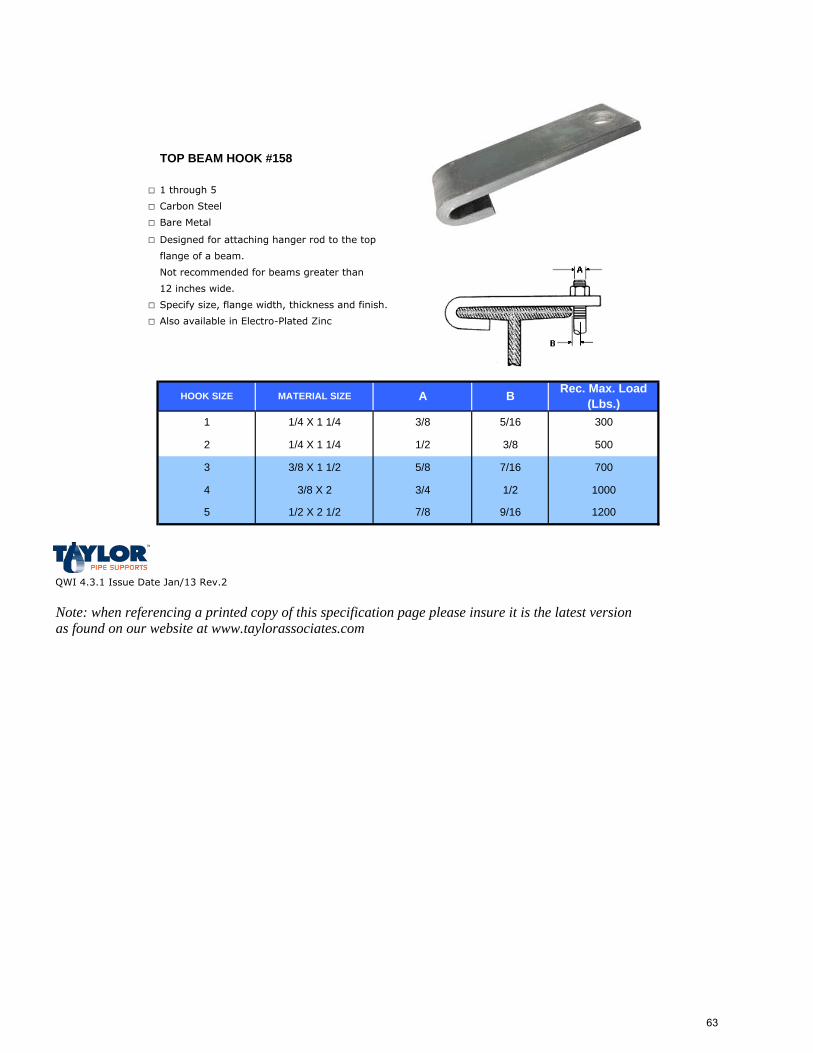
TOP BEAM HOOK #158
□ 1 through 5
□ Carbon Steel
□ Bare Metal
□ Designed for attaching hanger rod to the top
flange of a beam.
Not recommended for beams greater than
12 inches wide.
□ Specify size, flange width, thickness and finish.
□ Also available in Electro-Plated Zinc
QWI 4.3.1 Issue Date Jan/13 Rev.2
Note: when referencing a printed copy of this specification page please insure it is the latest version as found on our website at www.taylorassociates.com
1000
1200
Rec. Max. Load (Lbs.)
300
500
700
1/4 X 1 1/4
3/8 X 1 1/23
MATERIAL SIZE
1/4 X 1 1/4
HOOK SIZE
1/2 X 2 1/2
3/8 X 24
5
3/4
3/8
1/2
5/8
5/16
3/8
7/8
A
1
2
B
7/16
9/16
1/2
63
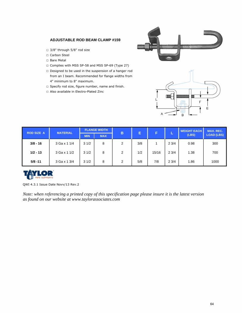
ADJUSTABLE ROD BEAM CLAMP #159
□ 3/8" through 5/8" rod size
□ Carbon Steel
□ Bare Metal
□ Complies with MSS SP-58 and MSS SP-69 (Type 27)
□ Designed to be used in the suspension of a hanger rod
from an I beam. Recommended for flange widths from
4" minimum to 8" maximum.
□ Specify rod size, figure number, name and finish.
□ Also available in Electro-Plated Zinc
MIN MAX
3/8 - 16 3 Ga x 1 1/4 3 1/2 8 2 3/8 1 2 3/4 0.98 300
1/2 - 13 3 Ga x 1 1/2 3 1/2 8 2 1/2 15/16 2 3/4 1.38 700
5/8 -11 3 Ga x 1 3/4 3 1/2 8 2 5/8 7/8 2 3/4 1.86 1000
QWI 4.3.1 Issue Date Novv/13 Rev.2
Note: when referencing a printed copy of this specification page please insure it is the latest version as found on our website at www.taylorassociates.com
ROD SIZE A MATERIALFLANGE WIDTH MAX. REC.
LOAD (LBS)B E F L WEIGHT EACH (LBS)
64
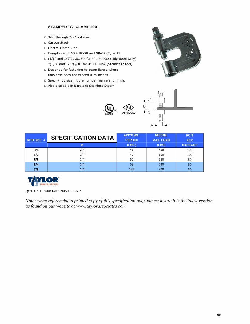
STAMPED "C" CLAMP #201
□ 3/8" through 7/8" rod size
□ Carbon Steel
□ Electro-Plated Zinc
□ Complies with MSS SP-58 and SP-69 (Type 23).
□ (3/8" and 1/2") CUL, FM for 4" I.P. Max (Mild Steel Only)
*(3/8" and 1/2") CUL, for 4" I.P. Max (Stainless Steel)
□ Designed for fastening to beam flange where
thickness does not exceed 0.75 inches.
□ Specify rod size, figure number, name and finish.
□ Also available in Bare and Stainless Steel*
PC'SPER
PACKAGE3/8 1001/2 1005/8 503/4 507/8 50
QWI 4.3.1 Issue Date Mar/12 Rev.5
Note: when referencing a printed copy of this specification page please insure it is the latest version as found on our website at www.taylorassociates.com
3/4
ROD SIZE A SPECIFICATION DATA
3/43/4
B
3/4
RECOM.MAX. LOAD
(LBS)
700630
400
550
1883/4
42 5006068
APP'X WT.PER 100(LBS.)
41
65
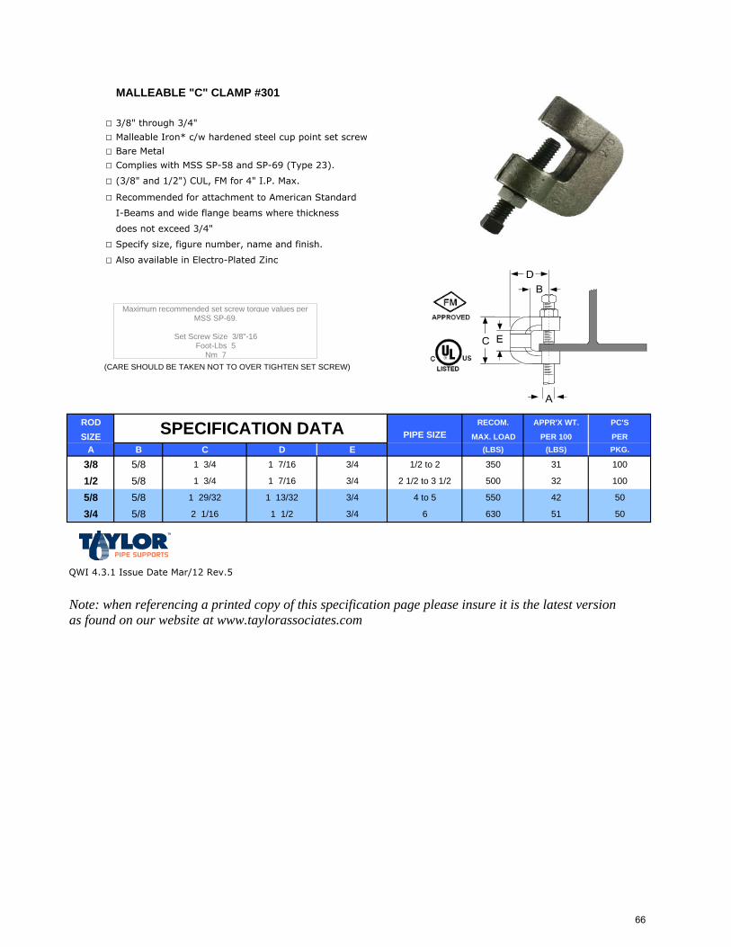
MALLEABLE "C" CLAMP #301
□ 3/8" through 3/4"
□ Malleable Iron* c/w hardened steel cup point set screw
□ Bare Metal
□ Complies with MSS SP-58 and SP-69 (Type 23).
□ (3/8" and 1/2") CUL, FM for 4" I.P. Max.
□ Recommended for attachment to American Standard
I-Beams and wide flange beams where thickness
does not exceed 3/4"
□ Specify size, figure number, name and finish.
□ Also available in Electro-Plated Zinc
ROD RECOM. APPR'X WT. PC'S
SIZE MAX. LOAD PER 100 PERA B C D E (LBS) (LBS) PKG.
3/8 5/8 1 3/4 1 7/16 3/4 1/2 to 2 350 31 100
1/2 5/8 1 3/4 1 7/16 3/4 2 1/2 to 3 1/2 500 32 100
5/8 5/8 1 29/32 1 13/32 3/4 4 to 5 550 42 50
3/4 5/8 2 1/16 1 1/2 3/4 6 630 51 50
QWI 4.3.1 Issue Date Mar/12 Rev.5
Note: when referencing a printed copy of this specification page please insure it is the latest version as found on our website at www.taylorassociates.com
SPECIFICATION DATA
Set Screw Size 3/8"-16
Maximum recommended set screw torque values perMSS SP-69.
Foot-Lbs 5Nm 7
(CARE SHOULD BE TAKEN NOT TO OVER TIGHTEN SET SCREW)
PIPE SIZE
66

PURLIN CLAMP #404
□ 3/8" Rod Size
□ Malleable iron c/w hardened steel cup point set screw.
□ Bare Metal
□ Complies with Manufacturers' Standardization Society
MSS SP-58 and SP-69 (Type 23)
□ Designed for use with large-lip rolled steel
purlins to eliminate the need to modify steel
purlin for standard C-Clamp
□ Specify rod size, figure number, name and finish.
□ Also available in Electro-Plated Zinc
ROD
SIZE
A
3/8 82 20
QWI 4.3.1 Issue Date Mar/12 Rev.4
Note: when referencing a printed copy of this specification page please insure it is the latest version as found on our website at www.taylorassociates.com
PC'S PER PKG.
APPROX. WEIGHT PER 100
PCS./LBSMAX. REC. LOAD/LBS
400
SPECIFICATION DATA
(CARE SHOULD BE TAKEN NOT TO OVER TIGHTEN SET SCREW)
Set Screw Size 3/8"-16
Maximum recommended set screw torque values perMSS SP-69.
Foot-Lbs 5Nm 7
MAX. PIPE SIZE
4"
67
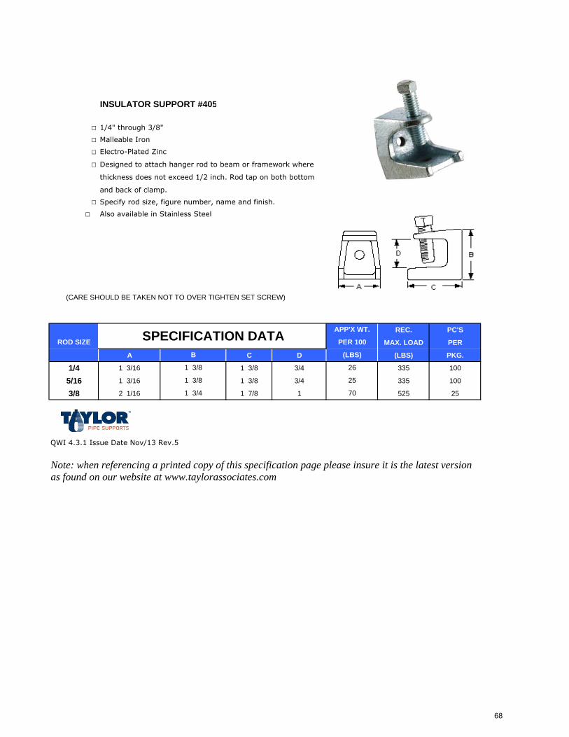
INSULATOR SUPPORT #405
□ 1/4" through 3/8"
□ Malleable Iron
□ Electro-Plated Zinc
□ Designed to attach hanger rod to beam or framework where
thickness does not exceed 1/2 inch. Rod tap on both bottom
and back of clamp.
□ Specify rod size, figure number, name and finish.
□ Also available in Stainless Steel
(CARE SHOULD BE TAKEN NOT TO OVER TIGHTEN SET SCREW)
REC. PC'S
MAX. LOAD PER
A C D (LBS) PKG.
1/4 1 3/16 1 3/8 3/4 335 100
5/16 1 3/16 1 3/8 3/4 335 100
3/8 2 1/16 1 7/8 1 525 25
QWI 4.3.1 Issue Date Nov/13 Rev.5
Note: when referencing a printed copy of this specification page please insure it is the latest version as found on our website at www.taylorassociates.com
ROD SIZE
1 3/8
B
SPECIFICATION DATA APP'X WT.
PER 100
(LBS)
26
1 3/8 25
1 3/4 70
68
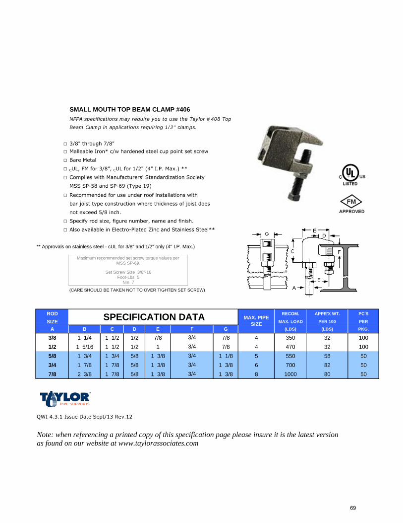
SMALL MOUTH TOP BEAM CLAMP #406NFPA specifications may require you to use the Taylor #408 Top
Beam Clamp in applications requiring 1/2" clamps.
□ 3/8" through 7/8"
□ Malleable Iron* c/w hardened steel cup point set screw
□ Bare Metal
□ CUL, FM for 3/8", CUL for 1/2" (4" I.P. Max.) **
□ Complies with Manufacturers' Standardization Society
MSS SP-58 and SP-69 (Type 19)
□ Recommended for use under roof installations with
bar joist type construction where thickness of joist does
not exceed 5/8 inch.
□ Specify rod size, figure number, name and finish.
□ Also available in Electro-Plated Zinc and Stainless Steel**
** Approvals on stainless steel - cUL for 3/8" and 1/2" only (4" I.P. Max.)
(CARE SHOULD BE TAKEN NOT TO OVER TIGHTEN SET SCREW)
ROD RECOM. APPR'X WT. PC'S
SIZE MAX. LOAD PER 100 PER
A B C D E G (LBS) (LBS) PKG.
3/8 1 1/4 1 1/2 1/2 7/8 7/8 4 350 32 1001/2 1 5/16 1 1/2 1/2 1 7/8 4 470 32 1005/8 1 3/4 1 3/4 5/8 1 3/8 1 1/8 5 550 58 503/4 1 7/8 1 7/8 5/8 1 3/8 1 3/8 6 700 82 507/8 2 3/8 1 7/8 5/8 1 3/8 1 3/8 8 1000 80 50
QWI 4.3.1 Issue Date Sept/13 Rev.12
Note: when referencing a printed copy of this specification page please insure it is the latest version as found on our website at www.taylorassociates.com
3/4
MSS SP-69.
Set Screw Size 3/8"-16
MAX. PIPE SIZE
3/43/43/4
F
3/4
SPECIFICATION DATA
Foot-Lbs 5Nm 7
Maximum recommended set screw torque values per
69
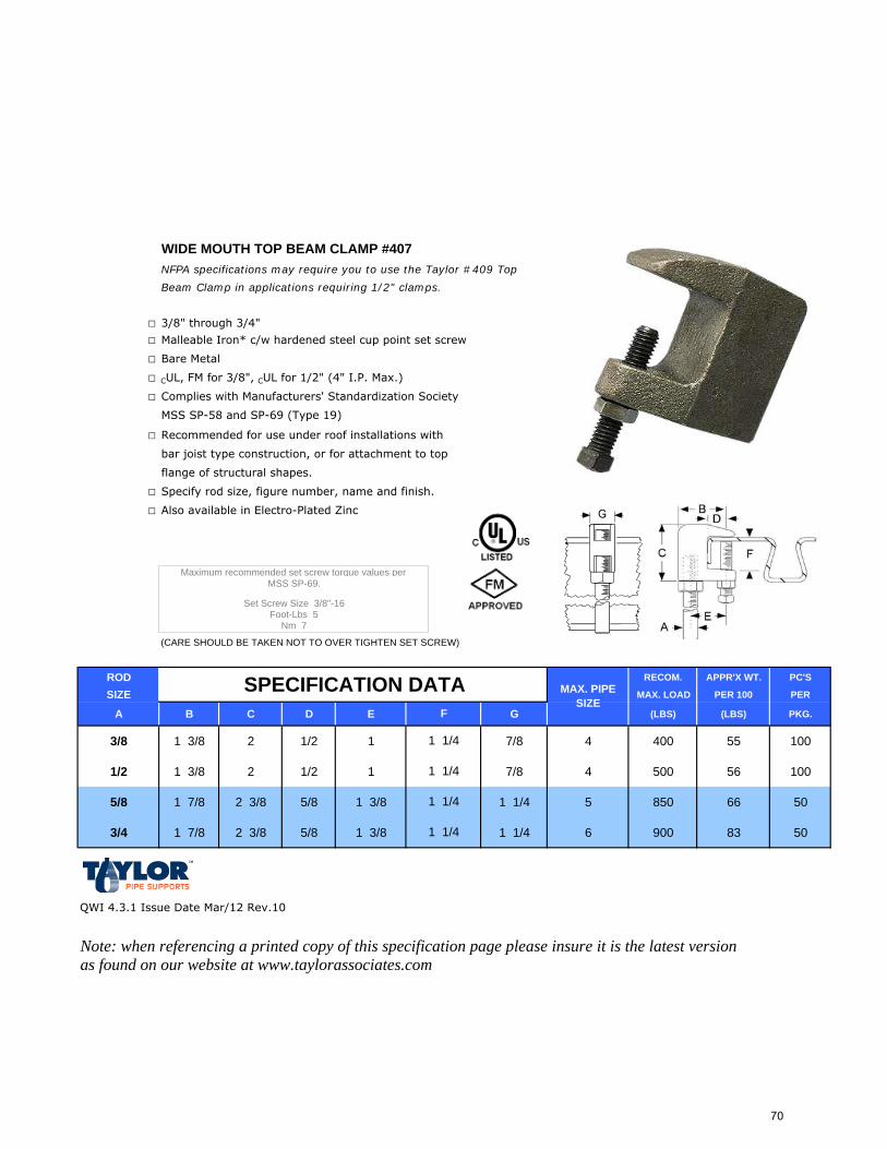
WIDE MOUTH TOP BEAM CLAMP #407NFPA specifications may require you to use the Taylor #409 Top
Beam Clamp in applications requiring 1/2" clamps.
□ 3/8" through 3/4"
□ Malleable Iron* c/w hardened steel cup point set screw
□ Bare Metal
□ CUL, FM for 3/8", CUL for 1/2" (4" I.P. Max.)
□ Complies with Manufacturers' Standardization Society
MSS SP-58 and SP-69 (Type 19)
□ Recommended for use under roof installations with
bar joist type construction, or for attachment to top
flange of structural shapes.
□ Specify rod size, figure number, name and finish.
□ Also available in Electro-Plated Zinc
(CARE SHOULD BE TAKEN NOT TO OVER TIGHTEN SET SCREW)
ROD RECOM. APPR'X WT. PC'S
SIZE MAX. LOAD PER 100 PER
A B C D E G (LBS) (LBS) PKG.
3/8 1 3/8 2 1/2 1 7/8 4 400 55 100
1/2 1 3/8 2 1/2 1 7/8 4 500 56 100
5/8 1 7/8 2 3/8 5/8 1 3/8 1 1/4 5 850 66 50
3/4 1 7/8 2 3/8 5/8 1 3/8 1 1/4 6 900 83 50
QWI 4.3.1 Issue Date Mar/12 Rev.10
Note: when referencing a printed copy of this specification page please insure it is the latest version as found on our website at www.taylorassociates.com
Set Screw Size 3/8"-16Foot-Lbs 5
Nm 7
Maximum recommended set screw torque values perMSS SP-69.
MAX. PIPE SIZE
1 1/4
F
1 1/4
SPECIFICATION DATA
1 1/4
1 1/4
70
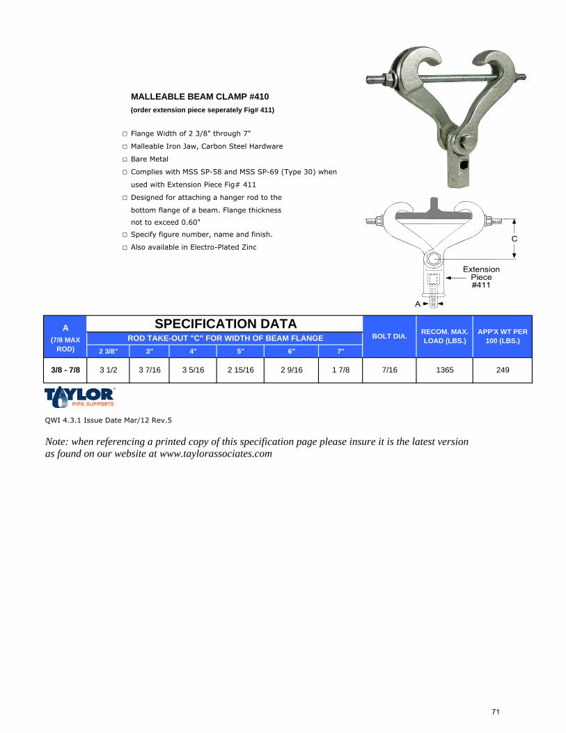
MALLEABLE BEAM CLAMP #410(order extension piece seperately Fig# 411)
□ Flange Width of 2 3/8" through 7"
□ Malleable Iron Jaw, Carbon Steel Hardware
□ Bare Metal
□ Complies with MSS SP-58 and MSS SP-69 (Type 30) when
used with Extension Piece Fig# 411
□ Designed for attaching a hanger rod to the
bottom flange of a beam. Flange thickness
not to exceed 0.60"
□ Specify figure number, name and finish.
□ Also available in Electro-Plated Zinc
A
2 3/8" 3" 4" 5" 6" 7"
QWI 4.3.1 Issue Date Mar/12 Rev.5
Note: when referencing a printed copy of this specification page please insure it is the latest version as found on our website at www.taylorassociates.com
3/8 - 7/8 3 1/2 3 7/16 7/16 1365 2493 5/16 2 15/16 2 9/16 1 7/8
RECOM. MAX. LOAD (LBS.)
APP'X WT PER 100 (LBS.)BOLT DIA.(7/8 MAX
ROD)
SPECIFICATION DATAROD TAKE-OUT "C" FOR WIDTH OF BEAM FLANGE
71
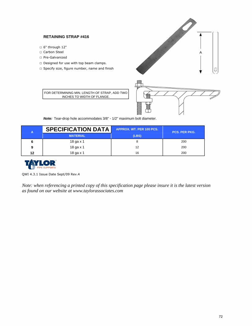
RETAINING STRAP #416
□ 6" through 12"
□ Carbon Steel
□ Pre-Galvanized
□ Designed for use with top beam clamps.
□ Specify size, figure number, name and finish
Note: Tear-drop hole accommodates 3/8" - 1/2" maximum bolt diameter.
6912
QWI 4.3.1 Issue Date Sept/09 Rev.4
Note: when referencing a printed copy of this specification page please insure it is the latest version as found on our website at www.taylorassociates.com
200
20018 ga x 118 ga x 1
FOR DETERMINING MIN. LENGTH OF STRAP, ADD TWO INCHES TO WIDTH OF FLANGE.
12
16
A PCS. PER PKG.
818 ga x 1
SPECIFICATION DATA APPROX. WT. PER 100 PCS.
(LBS)MATERIAL
200
A
72
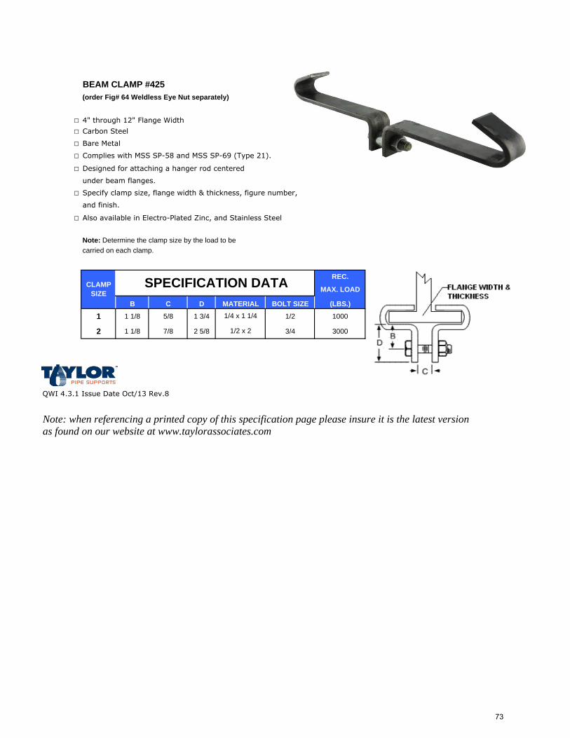
BEAM CLAMP #425(order Fig# 64 Weldless Eye Nut separately)
□ 4" through 12" Flange Width
□ Carbon Steel
□ Bare Metal
□ Complies with MSS SP-58 and MSS SP-69 (Type 21).
□ Designed for attaching a hanger rod centered
under beam flanges.
□ Specify clamp size, flange width & thickness, figure number,
and finish.
□ Also available in Electro-Plated Zinc, and Stainless Steel
Note: Determine the clamp size by the load to be carried on each clamp.
REC.
MAX. LOAD
B C D BOLT SIZE (LBS.)
1 1 1/8 5/8 1 3/4 1/2 1000
2 1 1/8 7/8 2 5/8 3/4 3000
QWI 4.3.1 Issue Date Oct/13 Rev.8
Note: when referencing a printed copy of this specification page please insure it is the latest version as found on our website at www.taylorassociates.com
1/2 x 2
CLAMP SIZE
SPECIFICATION DATAMATERIAL1/4 x 1 1/4
73
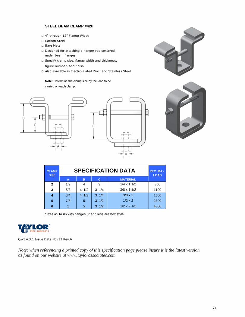
STEEL BEAM CLAMP #426
□ 4" through 12" Flange Width
□ Carbon Steel
□ Bare Metal
□ Designed for attaching a hanger rod centered
under beam flanges.
□ Specify clamp size, flange width and thickness,
figure number, and finish
□ Also available in Electro-Plated Zinc, and Stainless Steel
Note: Determine the clamp size by the load to be
carried on each clamp.
A B C2 1/2 4 3 8503 5/8 4 1/2 3 1/4 11004 3/4 4 1/2 3 1/4 15005 7/8 5 3 1/2 26006 1 5 3 1/2 4300
Sizes #5 to #6 with flanges 5" and less are box style
QWI 4.3.1 Issue Date Nov13 Rev.6
Note: when referencing a printed copy of this specification page please insure it is the latest version as found on our website at www.taylorassociates.com
1/2 x 2 1/2
1/4 x 1 1/23/8 x 1 1/2
3/8 x 21/2 x 2
SPECIFICATION DATAMATERIAL
REC. MAX. LOAD
CLAMP SIZE
74
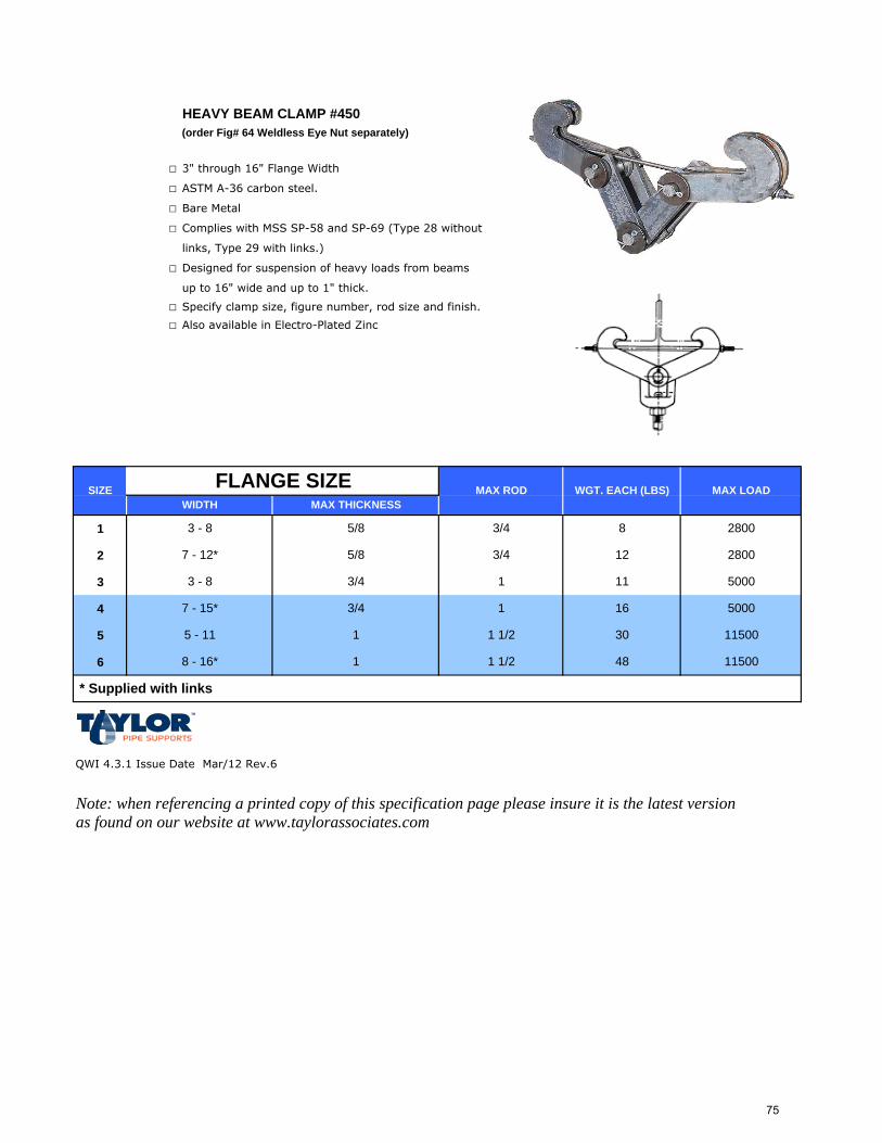
HEAVY BEAM CLAMP #450(order Fig# 64 Weldless Eye Nut separately)
□ 3" through 16" Flange Width
□ ASTM A-36 carbon steel.
□ Bare Metal
□ Complies with MSS SP-58 and SP-69 (Type 28 without
links, Type 29 with links.)
□ Designed for suspension of heavy loads from beams
up to 16" wide and up to 1" thick.
□ Specify clamp size, figure number, rod size and finish.
□ Also available in Electro-Plated Zinc
1
2
3
4
5
6
QWI 4.3.1 Issue Date Mar/12 Rev.6
Note: when referencing a printed copy of this specification page please insure it is the latest version as found on our website at www.taylorassociates.com
* Supplied with links
8 - 16* 1 1 1/2 48 11500
5000
5 - 11 1 1 1/2 30 11500
7 - 15* 3/4 1 16
2800
3 - 8 3/4 1 11 5000
7 - 12* 5/8 3/4 12
3 - 8 3/4 8 28005/8
MAX THICKNESSSIZE MAX LOADWGT. EACH (LBS)MAX RODFLANGE SIZE
WIDTH
75

CEILING FLANGE #28R
□ 1/4" - 1/2"
□ Malleable Iron
□ Electro-Plated Zinc
□ For attaching a hanger rod
□ to beams or ceilings.
□ Specify rod size, figure number, name and finish.
□ Also available in Bare, Copper Plate, Stainless Steel
ROD APP'X WT. PC'S
SIZE PER 100 PERA B C D E F G (LBS) PKG.
1/4" 3 5/16 1 3/8 1/2 3/16 2 1/4 1/4 17 100
3/8 3 5/16 1 3/8 1/2 3/16 2 1/4 1/4 17 100
1/2 3 5/16 1 3/8 1/2 3/16 2 1/4 1/4 18 100
QWI 4.3.1 Issue Date Apr/14 Rev.4
Note: when referencing a printed copy of this specification page please insure it is the latest version as found on our website at www.taylorassociates.com
180 #
180 #
MAX BOLT DIA.SPECIFICATION DATA RECOM.
MAX. LOAD(LBS)
180 #
76
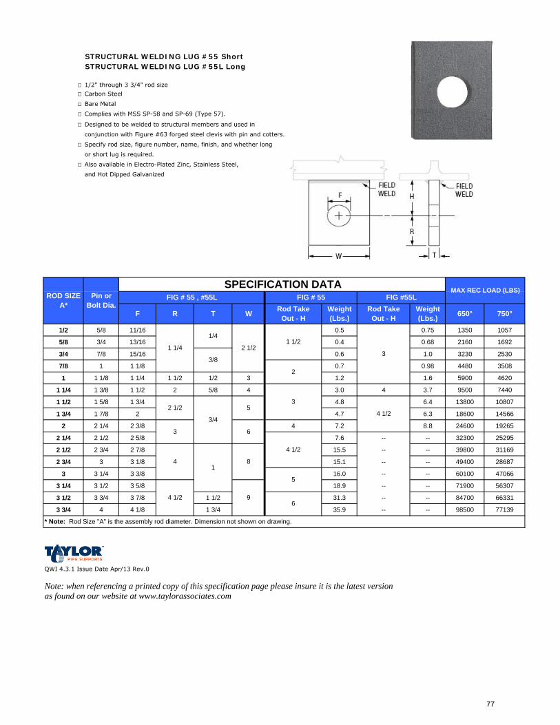
STRUCTURAL WELDING LUG #55 ShortSTRUCTURAL WELDING LUG #55L Long
□ 1/2" through 3 3/4" rod size
□ Carbon Steel
□ Bare Metal
□ Complies with MSS SP-58 and SP-69 (Type 57).
□ Designed to be welded to structural members and used in
conjunction with Figure #63 forged steel clevis with pin and cotters.
□ Specify rod size, figure number, name, finish, and whether long
or short lug is required.
□ Also available in Electro-Plated Zinc, Stainless Steel,
and Hot Dipped Galvanized
1/2 5/8 11/16 0.5 0.75 1350 1057
5/8 3/4 13/16 0.4 0.68 2160 1692
3/4 7/8 15/16 0.6 1.0 3230 2530
7/8 1 1 1/8 0.7 0.98 4480 3508
1 1 1/8 1 1/4 1 1/2 1/2 3 1.2 1.6 5900 4620
1 1/4 1 3/8 1 1/2 2 5/8 4 3.0 4 3.7 9500 7440
1 1/2 1 5/8 1 3/4 4.8 6.4 13800 10807
1 3/4 1 7/8 2 4.7 6.3 18600 14566
2 2 1/4 2 3/8 4 7.2 8.8 24600 19265
2 1/4 2 1/2 2 5/8 7.6 -- -- 32300 25295
2 1/2 2 3/4 2 7/8 15.5 -- -- 39800 31169
2 3/4 3 3 1/8 15.1 -- -- 49400 28687
3 3 1/4 3 3/8 16.0 -- -- 60100 47066
3 1/4 3 1/2 3 5/8 18.9 -- -- 71900 56307
3 1/2 3 3/4 3 7/8 1 1/2 31.3 -- -- 84700 66331
3 3/4 4 4 1/8 1 3/4 35.9 -- -- 98500 77139
QWI 4.3.1 Issue Date Apr/13 Rev.0
Note: when referencing a printed copy of this specification page please insure it is the latest version as found on our website at www.taylorassociates.com
FIG #55LWeight (Lbs.) 650°
ROD SIZE A*
Pin or Bolt Dia. Rod Take
Out - HWeight (Lbs.)F R T
FIG # 55 , #55LSPECIFICATION DATA
FIG # 55
750°
MAX REC LOAD (LBS)
1 1/4
2 1/2
2 1/2
5
3
4 1/2
Rod Take Out - HW
1 1/2
2
3
1/4
3/8
3/4
1
4 1/2
* Note: Rod Size "A" is the assembly rod diameter. Dimension not shown on drawing.
6
8
9
5
6
3
4
4 1/2
77
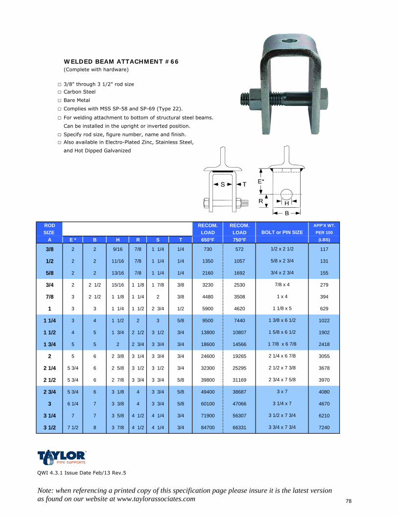
WELDED BEAM ATTACHMENT #66(Complete with hardware)
□ 3/8" through 3 1/2" rod size
□ Carbon Steel
□ Bare Metal
□ Complies with MSS SP-58 and SP-69 (Type 22).
□ For welding attachment to bottom of structural steel beams.
Can be installed in the upright or inverted position.
□ Specify rod size, figure number, name and finish.
□ Also available in Electro-Plated Zinc, Stainless Steel,
and Hot Dipped Galvanized
ROD RECOM. RECOM. APP'X WT.SIZE LOAD LOAD PER 100
A E * B H R S T 650°F 750°F (LBS)
3/8 2 2 9/16 7/8 1 1/4 1/4 730 572 117
1/2 2 2 11/16 7/8 1 1/4 1/4 1350 1057 131
5/8 2 2 13/16 7/8 1 1/4 1/4 2160 1692 155
3/4 2 2 1/2 15/16 1 1/8 1 7/8 3/8 3230 2530 279
7/8 3 2 1/2 1 1/8 1 1/4 2 3/8 4480 3508 394
1 3 3 1 1/4 1 1/2 2 3/4 1/2 5900 4620 629
1 1/4 3 4 1 1/2 2 3 5/8 9500 7440 1022
1 1/2 4 5 1 3/4 2 1/2 3 1/2 3/4 13800 10807 1902
1 3/4 5 5 2 2 3/4 3 3/4 3/4 18600 14566 2418
2 5 6 2 3/8 3 1/4 3 3/4 3/4 24600 19265 3055
2 1/4 5 3/4 6 2 5/8 3 1/2 3 1/2 3/4 32300 25295 3678
2 1/2 5 3/4 6 2 7/8 3 3/4 3 3/4 5/8 39800 31169 3970
2 3/4 5 3/4 6 3 1/8 4 3 3/4 5/8 49400 38687 4080
3 6 1/4 7 3 3/8 4 3 3/4 5/8 60100 47066 4670
3 1/4 7 7 3 5/8 4 1/2 4 1/4 3/4 71900 56307 6210
3 1/2 7 1/2 8 3 7/8 4 1/2 4 1/4 3/4 84700 66331 7240
QWI 4.3.1 Issue Date Feb/13 Rev.5
Note: when referencing a printed copy of this specification page please insure it is the latest version as found on our website at www.taylorassociates.com
2 1/2 x 7 3/8
7/8 x 4
1 x 4
1 1/8 x 5
1 5/8 x 6 1/2
1 7/8 x 6 7/8
1 3/8 x 6 1/2
2 1/4 x 6 7/8
3/4 x 2 3/4
BOLT or PIN SIZE
1/2 x 2 1/2
5/8 x 2 3/4
3 3/4 x 7 3/4
2 3/4 x 7 5/8
3 x 7
3 1/4 x 7
3 1/2 x 7 3/4
78
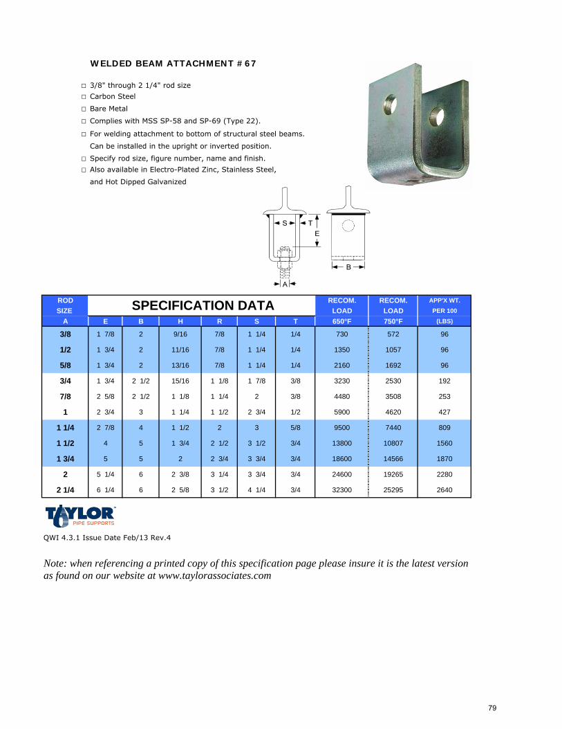
WELDED BEAM ATTACHMENT #67
□ 3/8" through 2 1/4" rod size
□ Carbon Steel
□ Bare Metal
□ Complies with MSS SP-58 and SP-69 (Type 22).
□ For welding attachment to bottom of structural steel beams.
Can be installed in the upright or inverted position.
□ Specify rod size, figure number, name and finish.
□ Also available in Electro-Plated Zinc, Stainless Steel,
and Hot Dipped Galvanized
ROD RECOM. RECOM. APP'X WT.SIZE LOAD LOAD PER 100
A E B H R S T 650°F 750°F (LBS)
3/8 1 7/8 2 9/16 7/8 1 1/4 1/4 730 572 96
1/2 1 3/4 2 11/16 7/8 1 1/4 1/4 1350 1057 96
5/8 1 3/4 2 13/16 7/8 1 1/4 1/4 2160 1692 96
3/4 1 3/4 2 1/2 15/16 1 1/8 1 7/8 3/8 3230 2530 192
7/8 2 5/8 2 1/2 1 1/8 1 1/4 2 3/8 4480 3508 253
1 2 3/4 3 1 1/4 1 1/2 2 3/4 1/2 5900 4620 427
1 1/4 2 7/8 4 1 1/2 2 3 5/8 9500 7440 809
1 1/2 4 5 1 3/4 2 1/2 3 1/2 3/4 13800 10807 1560
1 3/4 5 5 2 2 3/4 3 3/4 3/4 18600 14566 1870
2 5 1/4 6 2 3/8 3 1/4 3 3/4 3/4 24600 19265 2280
2 1/4 6 1/4 6 2 5/8 3 1/2 4 1/4 3/4 32300 25295 2640
QWI 4.3.1 Issue Date Feb/13 Rev.4
Note: when referencing a printed copy of this specification page please insure it is the latest version as found on our website at www.taylorassociates.com
SPECIFICATION DATA
79
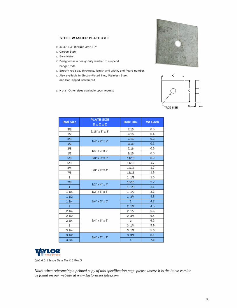
STEEL WASHER PLATE #80
□ 3/16" x 3" through 3/4" x 7"
□ Carbon Steel
□ Bare Metal
□ Designed as a heavy duty washer to suspend
hanger rods.
□ Specify rod size, thickness, length and width, and figure number.
□ Also available in Electro-Plated Zinc, Stainless Steel,
and Hot Dipped Galvanized
□ Note: Other sizes available upon request
3/8 7/161/2 9/163/8 7/161/2 9/163/8 7/161/2 9/165/8 11/165/8 11/163/4 13/167/8 15/161 1 1/8
7/8 15/161 1 1/8
1 1/4 1 1/21 1/2 1 3/41 3/4 2
2 2 1/42 1/4 2 1/22 1/2 2 3/42 3/4 3
3 3 1/43 1/4 3 1/23 1/2 3 3/43 3/4 4
QWI 4.3.1 Issue Date Mar/13 Rev.3
Note: when referencing a printed copy of this specification page please insure it is the latest version as found on our website at www.taylorassociates.com
8.17.8
1/2" x 5" x 5" 3.34.8
3/4" x 5" x 5" 4.7
3/4" x 7" x 7"
4.5
5.9
2.22.1
1.71.61.6
0.60.60.91.7
Hole Dia. Wt Each
3/16" x 3" x 3"
1/4" x 2" x 2"
D x C x C0.50.40.30.3
6.66.46.2
5.6
Rod SizePLATE SIZE
3/8" x 3" x 3"
1/4" x 3" x 3"
3/8" x 4" x 4"
1/2" x 4" x 4"
3/4" x 6" x 6"
80
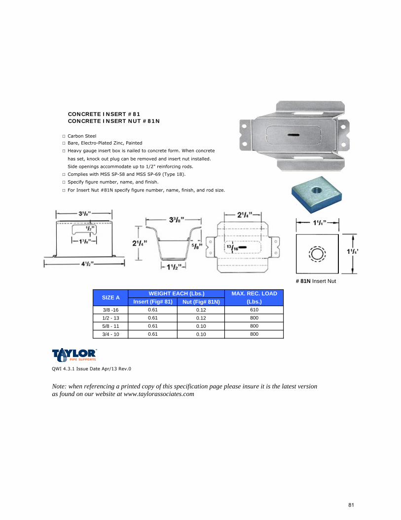
CONCRETE INSERT #81CONCRETE INSERT NUT #81N
□ Carbon Steel
□ Bare, Electro-Plated Zinc, Painted
□ Heavy gauge insert box is nailed to concrete form. When concrete
has set, knock out plug can be removed and insert nut installed.
Side openings accommodate up to 1/2" reinforcing rods.
□ Complies with MSS SP-58 and MSS SP-69 (Type 18).
□ Specify figure number, name, and finish.
□ For Insert Nut #81N specify figure number, name, finish, and rod size.
Nut (Fig# 81N)3/8 -16 0.121/2 - 13 0.125/8 - 11 0.103/4 - 10 0.10
QWI 4.3.1 Issue Date Apr/13 Rev.0
Note: when referencing a printed copy of this specification page please insure it is the latest version as found on our website at www.taylorassociates.com
0.610.610.61 800
610800800
MAX. REC. LOAD(Lbs.)Insert (Fig# 81)
0.61
SIZE AWEIGHT EACH (Lbs.)
# 81N Insert Nut
81
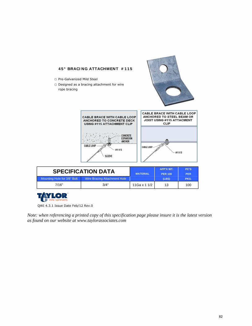
45° BRACING ATTACHMENT #115
□ Pre-Galvanized Mild Steel
□ Designed as a bracing attachment for wire
rope bracing
APP'X WT. PC'S
PER 100 PER
(LBS) PKG.
11Ga x 1 1/2 13 100
QWI 4.3.1 Issue Date Feb/12 Rev.0
Note: when referencing a printed copy of this specification page please insure it is the latest version as found on our website at www.taylorassociates.com
MATERIAL
Mounting Hole for 3/8" Bolt
7/16"
SPECIFICATION DATAWire Bracing Attachment Hole
3/4"
82
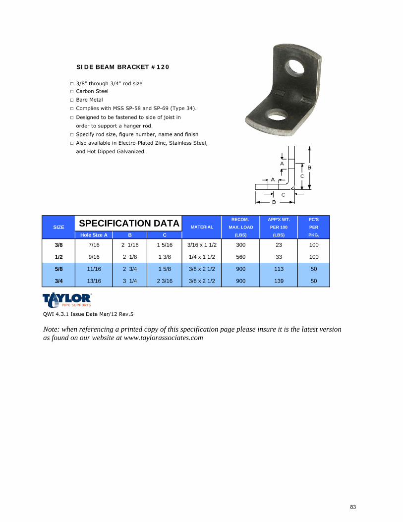
SIDE BEAM BRACKET #120
□ 3/8" through 3/4" rod size
□ Carbon Steel
□ Bare Metal
□ Complies with MSS SP-58 and SP-69 (Type 34).
□ Designed to be fastened to side of joist in
order to support a hanger rod.
□ Specify rod size, figure number, name and finish
□ Also available in Electro-Plated Zinc, Stainless Steel,
and Hot Dipped Galvanized
RECOM. APP'X WT. PC'S
SIZE MAX. LOAD PER 100 PER
Hole Size A B C (LBS) (LBS) PKG.
3/8 7/16 2 1/16 1 5/16 3/16 x 1 1/2 300 23 100
1/2 9/16 2 1/8 1 3/8 1/4 x 1 1/2 560 33 100
5/8 11/16 2 3/4 1 5/8 3/8 x 2 1/2 900 113 50
3/4 13/16 3 1/4 2 3/16 3/8 x 2 1/2 900 139 50
QWI 4.3.1 Issue Date Mar/12 Rev.5
Note: when referencing a printed copy of this specification page please insure it is the latest version as found on our website at www.taylorassociates.com
MATERIALSPECIFICATION DATA
83
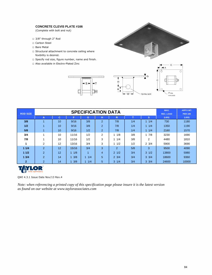
CONCRETE CLEVIS PLATE #166(Complete with bolt and nut)
□ 3/8" through 2" Rod
□ Carbon Steel
□ Bare Metal
□ Structural attachment to concrete ceiling where
fexibility is desired.
□ Specify rod size, figure number, name and finish.
□ Also available in Electro-Plated Zinc
MAX. APP'X WT.
REC. LOAD PER 100
A C F G H R T S (LBS) (LBS)
3/8 1 10 9/16 3/8 2 7/8 1/4 1 1/4 730 11801/2 1 10 9/16 3/8 2 7/8 1/4 1 1/4 1350 11905/8 1 10 9/16 1/2 2 7/8 1/4 1 1/4 2160 15703/4 1 10 11/16 1/2 2 1 1/8 3/8 1 7/8 3230 16907/8 1 10 11/16 1/2 3 1 1/4 3/8 2 4480 18101 2 12 13/16 3/4 3 1 1/2 1/2 2 3/4 5900 3690
1 1/4 2 12 15/16 3/4 3 2 5/8 3 9500 40901 1/2 2 12 1 1/8 1 4 2 1/2 3/4 3 1/2 13800 59801 3/4 2 14 1 3/8 1 1/4 5 2 3/4 3/4 3 3/4 18600 9360
2 2 14 1 3/8 1 1/4 5 3 1/4 3/4 3 3/4 24600 10000
QWI 4.3.1 Issue Date Nov/13 Rev.4
Note: when referencing a printed copy of this specification page please insure it is the latest version as found on our website at www.taylorassociates.com
SPECIFICATION DATAROD SIZE
84
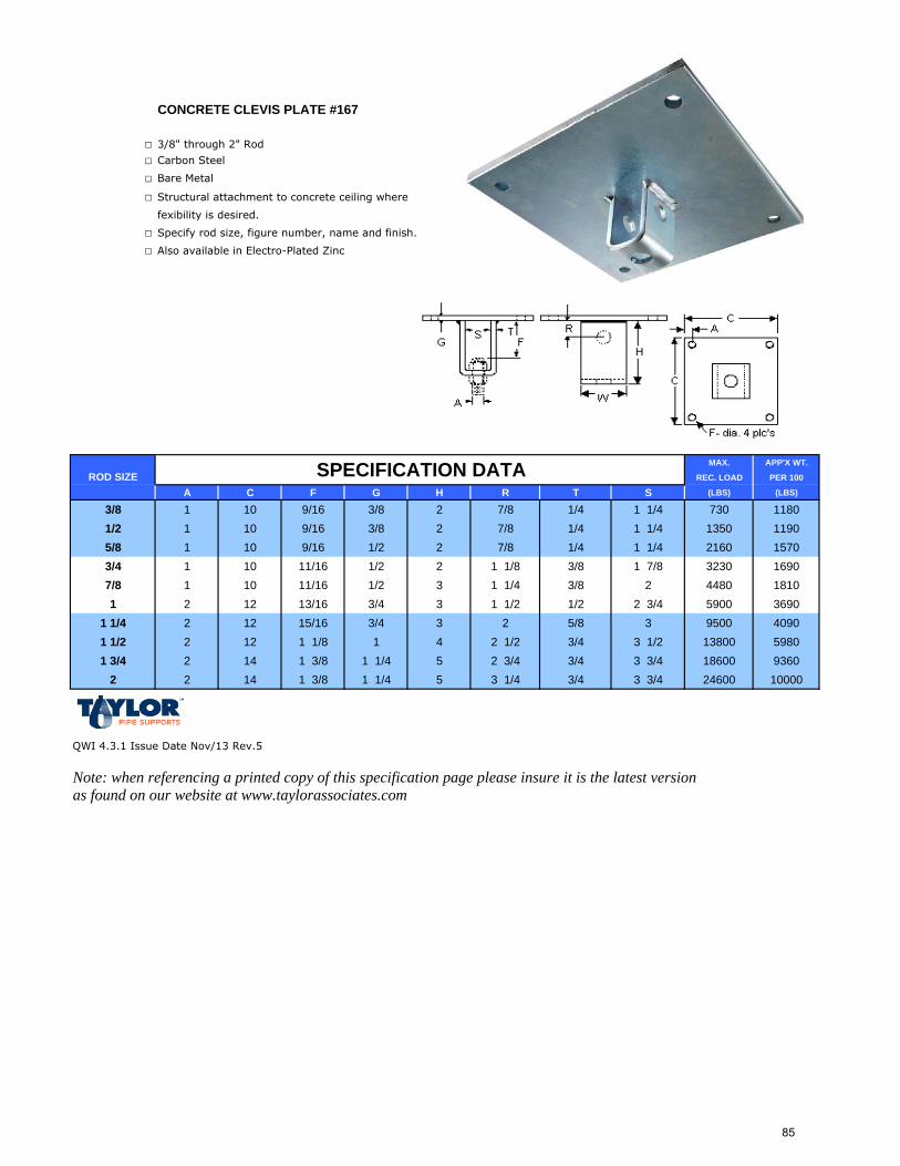
CONCRETE CLEVIS PLATE #167
□ 3/8" through 2" Rod
□ Carbon Steel
□ Bare Metal
□ Structural attachment to concrete ceiling where
fexibility is desired.
□ Specify rod size, figure number, name and finish.
□ Also available in Electro-Plated Zinc
MAX. APP'X WT.
REC. LOAD PER 100
A C F G H R T S (LBS) (LBS)
3/8 1 10 9/16 3/8 2 7/8 1/4 1 1/4 730 11801/2 1 10 9/16 3/8 2 7/8 1/4 1 1/4 1350 11905/8 1 10 9/16 1/2 2 7/8 1/4 1 1/4 2160 15703/4 1 10 11/16 1/2 2 1 1/8 3/8 1 7/8 3230 16907/8 1 10 11/16 1/2 3 1 1/4 3/8 2 4480 18101 2 12 13/16 3/4 3 1 1/2 1/2 2 3/4 5900 3690
1 1/4 2 12 15/16 3/4 3 2 5/8 3 9500 40901 1/2 2 12 1 1/8 1 4 2 1/2 3/4 3 1/2 13800 59801 3/4 2 14 1 3/8 1 1/4 5 2 3/4 3/4 3 3/4 18600 9360
2 2 14 1 3/8 1 1/4 5 3 1/4 3/4 3 3/4 24600 10000
QWI 4.3.1 Issue Date Nov/13 Rev.5
Note: when referencing a printed copy of this specification page please insure it is the latest version as found on our website at www.taylorassociates.com
SPECIFICATION DATAROD SIZE
85
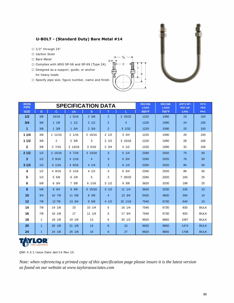
U-BOLT - (Standard Duty) Bare Metal #14
□ 1/2" through 24"
□ Carbon Steel
□ Bare Metal
□ Complies with MSS SP-58 and SP-69 (Type 24).
□ Designed as a support, guide, or anchor
for heavy loads.
□ Specify pipe size, figure number, name and finish.
IRON RECOM. RECOM. APP'X WT. PC'SPIPE LOAD LOAD PER 100 PERSIZE D C c/c S T L 650°F 750°F (LBS) PKG.
QWI 4.3.1 Issue Date Jan/14 Rev.10
Note: when referencing a printed copy of this specification page please insure it is the latest version as found on our website at www.taylorassociates.com
SPECIFICATION DATA
3 5 3/4 2260
9 5/8
10 1/4
6 1/16 3230
50804 1/4 3 6 1/4 2260 20203 1/2 1/2 4 1/16 4 9/16
3 1/2
3 2 1/2
3 9/16 4 1/16 4
2 1/2 1/2 2 15/16
50
5070
76
10028
32
3 15/16
100
1090
3 7/16
3 5/16 2 3/4 4 1/2
3 13/16 3 5 1/4
2 3/8 2 7/16 2 13/16
3/8 1 11/16
1 1/2 3/8 2 2 3/8
3/4 3/8 1 1/8
1 3/8 1 3/8
1 1/2
2 1/161 1/4
100
100232 3/8 2 2 25/32 10901220
2 3
2 15/16
2 1/2
1 3/4
2 1/2
2 3/4 2
3 3/4 100
10025109012203 1/32
241220 1090
26
1/2 3/8 15/16 1 5/16
6
8
10
5
20
24
12
14
16
18
6 1/8
5/8
5/8
3/4
1/2
6 3/4
8 3/4
10 7/8
5 5/8
7 3/8
7/8
7/8
12 7/8
14 1/8
8 3/8
9 3/8
11 5/8
13 3/4
6 15/16
15
1220
1220
1090
2020
2020
1090
3 1/2 9 3/8 3620
11 1/4 3620 3230
4 13 3/4 5420 4830
3 1/2
4 1/2 15 1/16 7540 6730
5 16 1/4 7540 6730
50
198 25
100 25
10
830 BULK
226 10
394 10
7/8 16 1/8 17 11 1/4 BULK
18 1/8 19 1/8 13 6 20 1/2 9920 8850
5 17 3/4
BULK
1 20 1/8 21 1/8 14 6 22 9920 8850
1
1 24 1/8 25 1/8 16 1708 BULK
1474 BULK
6 27 9920 8850
4 1/2 3 6 3/4
5
4 1/2 4 9/16 5 1/16 2260 2020
1220
1067
9207540 6730
640
86
2260
20203 7 25/32 2260
86
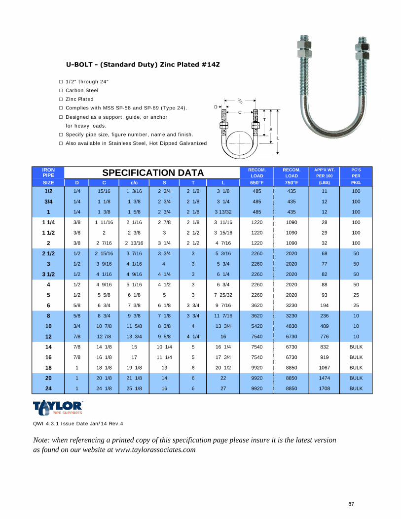
U-BOLT - (Standard Duty) Zinc Plated #14Z
□ 1/2" through 24"
□ Carbon Steel
□ Zinc Plated
□ Complies with MSS SP-58 and SP-69 (Type 24).
□ Designed as a support, guide, or anchor
for heavy loads.
□ Specify pipe size, figure number, name and finish.
□ Also available in Stainless Steel, Hot Dipped Galvanized
IRON RECOM. RECOM. APP'X WT. PC'SPIPE LOAD LOAD PER 100 PERSIZE D C c/c S T L 650°F 750°F (LBS) PKG.
QWI 4.3.1 Issue Date Jan/14 Rev.4
Note: when referencing a printed copy of this specification page please insure it is the latest version as found on our website at www.taylorassociates.com
1 3/8 2 3/4
3 15/16
2 13/16
3 13/32
2 3/8
4 1/2 3 6 3/4
2 1/8 3 11/16
5 3/16
4 1/2 4 9/16 5 1/16
1067
5 3 7 25/32 2260 2020 93
9197540 6730
6 27 9920 8850 1708 BULK
1474 BULK
1 24 1/8 25 1/8 16
BULK
1 20 1/8 21 1/8 14 6 22 9920 8850
1
BULK
18 1/8 19 1/8 13 6 20 1/2 9920 8850
5 17 3/47/8 16 1/8 17 11 1/4
776 10
832 BULK
236 10
489 10
88 50
194 25
25
5 16 1/4 7540 6730
4 1/4 16 7540 6730
4 13 3/4 5420 4830
3 3/4 11 7/16 3620 3230
3 3/4 9 7/16 3620 3230
2260 2020
1220
1220
1220
1090
2020
2020
1090
1090
9 3/8
11 5/8
13 3/4
15
7/8
7/8
12 7/8
14 1/8
6 1/8
5/8
5/8
3/4
1/2
6 3/4
8 3/4
10 7/8
5 5/8
7 3/8
20
24
12
14
16
18
6
8
10
5
1/2 1/4 15/16 1 3/16
12485 435
28 100
100121 5/8
2 1/16 2 7/8
4354852 3/4 2 1/8
100
100112 3/4 2 1/8 3 1/8 435485
2 1/8 3 1/43/4 1/4 1 1/8
1 1/4 1 3/8
1 1/4 3/8 1 11/16
2 3/8 2 7/16
1 1/2 3/8 2 10029
2 1/2 1/2 2 15/16 3 7/16
3 1/4 2 1/2 4 7/16 32
4 1/16 4
100
50
5068
77
22603 3/4 3
SPECIFICATION DATA
3 1/2 1/2 4 1/16 4 9/16
3 1/2
3 2 1/2
3 9/16
50824 1/4 3 6 1/4 2260 2020
3 5 3/4 2260
9 5/8
10 1/4
6 1/8
7 1/8
8 3/8
87
HEX. NUTS - Zinc #15Z
□ 3/8" through 3/4"
□ Carbon Steel Grade 2
□ Zinc Plated
□ Specify size, figure number, and name.
QWI 4.3.1 Issue Date Feb/08 Rev.0
Note: when referencing a printed copy of this specification page please insure it is the latest version as found on our website at www.taylorassociates.com
5/8-11
1/2-13
SIZE PKG. QTY. APPROX. WT. Per 100 PCS
3/8-16
100
2
4
100
50 7
3/4-10 50 12
88
20° SWIVEL ROD EXTENSION #17W
□ 3/8"
□ Carbon Steel
□ Electro-Zinc Plated
□ The extension piece, when installed in the hanger assembly,
allows for movement up to 20°. Threading at both ends is
3/8"-16 for use with standard threaded rod or hardware.
Height adjustable with an inspection hole in collar to check the
screw in depth of the threaded rod. Assemblies will hang "plumb"
from the pivot point or, where movement is required, the
hanging assembly will accommodate.
□ Specify size, figure number, and name.
QWI 4.3.1 Issue Date Feb/08 Rev.0
Note: when referencing a printed copy of this specification page please insure it is the latest version as found on our website at www.taylorassociates.com
600#
MAX LOADAPPROX. WT. Per 100 PCS
9
SIZE BOX QTY.
3/8" 25
89
ROD WITH EYE #53
□ 2 3/4" through 5"
□ Carbon Steel
□ A large diameter rod with eye end for
load ratings through 184,000 pounds.
□ Specify rod size, figure number, name, finish
and "L" dimension. Indicate if desired thread length
is other than standard.
□ Also available in Galvanized
ROD WT.* WT/Ft
SIZE MIN. AdditionalA B D E H L (MIN) R T W LENGTH LENGTH
2 3/4 9 5/8 12 3 3/4 3 1/8 19 3 5/8 1 1/2 6 49400 38687 36 20
3 11 12 4 3 3/8 20 4 1 1/2 6 60100 47066 43 24
3 1/4 12 1/4 12 4 3 5/8 21 4 1/4 1 1/2 7 71900 56307 55 28
3 1/2 12 1/2 15 4 3/4 3 7/8 24 4 1/2 2 7 84700 66331 67 33
3 3/4 13 7/8 15 5 4 1/8 25 4 7/8 2 7 1/2 98500 77139 80 37
4 15 1/8 15 5 4 3/8 26 5 1/8 2 8 1/2 113400 88807 97 43
4 1/4 16 1/4 18 5 1/4 4 5/8 30 5 1/2 2 9 1/2 129400 101337 127 48
4 1/2 16 18 5 3/4 4 7/8 30 5 3/4 2 1/2 8 1/2 146600 114807 131 54
4 3/4 17 18 5 3/4 5 1/8 31 6 2 1/2 9 1/2 164700 128982 154 60
5 17 7/8 18 6 1/4 5 3/8 32 6 3/8 2 1/2 10 184000 144096 175 67
QWI 4.3.1 Issue Date Mar/13 Rev.0
Note: when referencing a printed copy of this specification page please insure it is the latest version as found on our website at www.taylorassociates.com
*Weight calculated with minimum "L" for standard thread • Furnished with 4 UN series threads
MAX. LOAD
650° F 750° FSPECIFICATION DATA
90
ALL THREADED ROD #54
□ 3/8"-16 x 10' through 1 1/2"-6 x 10'
□ *Mild Steel - Grade 2
□ Zinc Plated
□ Used in attaching hangers to structural
attachments.
□ Specify thread size, length, figure number, name and finish.
□ Also available in Bare, Stanless Steel, and Hot Dipped Galvanized
* Base material is C1008-C1020, conforming to the requirements of ASTM A307 Grade A spec, class 2 thread.
SPECIFICATION DATA
MASTER
Note: Other thread sizes and lengths available upon request
QWI 4.3.1 Issue Date June/14 Rev.3
Note: when referencing a printed copy of this specification page please insure it is the latest version as found on our website at www.taylorassociates.com
13800 108071 1/2" - 6 1 1 5.15
9500 7440
1/4" - 20 500 PCS
1 1/4" - 7 1 1 3.56
4480 3508
5900 4620
7/8" - 9 60 PCS 3 PCS 1.69
1" - 8 60 PCS 3 PCS 2.23
MAX. SAFE LOAD (LBS) ROD
TEMPERATURE, 650°
MAX. SAFE LOAD (LBS) ROD
TEMPERATURE, 750°
0.29 730 572
0.12 240 --
1057
1692
1350
21600.845/8" - 11
3/4" - 10 32305 PCS
5 PCS
3/8" - 16
BUNDLE QUANTITIES
15 PCS
0.53
LBS. WEIGHT PER FOOT
25 PCS
2530
THREAD SIZE
10 PCS
INNER
1.22
300 PCS
1/2" - 13
100 PCS
200 PCS
100 PCS
91
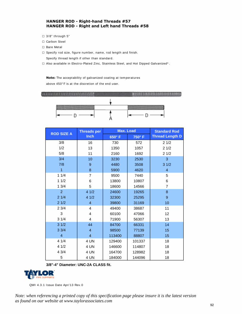
HANGER ROD - Right-hand Threads #57HANGER ROD - Right and Left hand Threads #58
□ 3/8" through 5"
□ Carbon Steel
□ Bare Metal
□ Specify rod size, figure number, name, rod length and finish.
Specify thread length if other than standard.
□ Also available in Electro-Plated Zinc, Stainless Steel, and Hot Dipped Galvanized*.
Note: The acceptability of galvanized coating at temperatures
above 450°F is at the discretion of the end user.
650° F 750° F16 730 572 2 1/213 1350 1057 2 1/211 2160 1692 2 1/210 3230 2530 39 4480 3508 3 1/28 5900 4620 47 9500 7440 56 13800 10807 65 18600 14566 7
4 1/2 24600 19265 84 1/2 32300 25295 9
4 39800 31169 104 49400 38687 114 60100 47066 124 71900 56307 13
44 84700 66331 144 98500 77139 154 113400 88807 15
4 UN 129400 101337 184 UN 146600 114807 184 UN 164700 128982 184 UN 184000 144096 18
3/8"-4" Diameter: UNC-2A CLASS fit.
QWI 4.3.1 Issue Date Apr/13 Rev.0
Note: when referencing a printed copy of this specification page please insure it is the latest version as found on our website at www.taylorassociates.com
3/81/25/83/47/8
ROD SIZE AMax. Load
3 3/4
1 3/42
2 1/42 1/2
Standard Rod Thread Length D
Threads per Inch
1
4
1 1/41 1/2
2 3/43
3 1/43 1/2
4 1/44 1/24 3/4
5
92
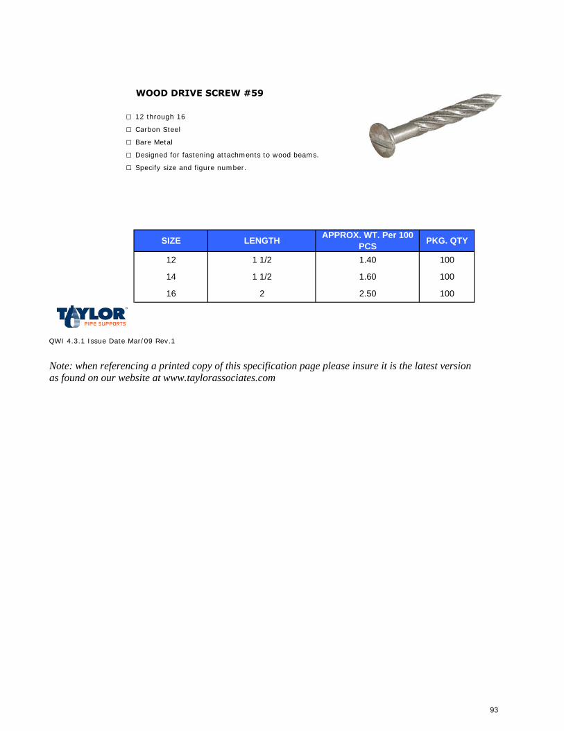
WOOD DRIVE SCREW #59
□ 12 through 16
□ Carbon Steel
□ Bare Metal
□ Designed for fastening attachments to wood beams.
□ Specify size and figure number.
QWI 4.3.1 Issue Date Mar/09 Rev.1
Note: when referencing a printed copy of this specification page please insure it is the latest version as found on our website at www.taylorassociates.com
APPROX. WT. Per 100 PCS
12
1 1/2
1 1/2 1.40
1.6014
SIZE LENGTH
16 2 2.50
PKG. QTY
100
100
100
93
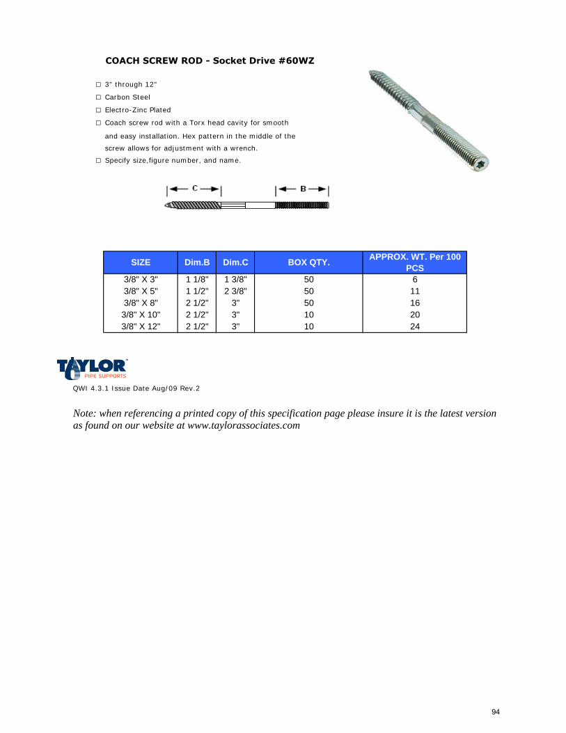
COACH SCREW ROD - Socket Drive #60WZ
□ 3" through 12"
□ Carbon Steel
□ Electro-Zinc Plated
□ Coach screw rod with a Torx head cavity for smooth
and easy installation. Hex pattern in the middle of the
screw allows for adjustment with a wrench.
□ Specify size,figure number, and name.
QWI 4.3.1 Issue Date Aug/09 Rev.2
Note: when referencing a printed copy of this specification page please insure it is the latest version as found on our website at www.taylorassociates.com
2 1/2"2 1/2"2 1/2"
1 3/8"2 3/8"
3"3"3" 10 24
50 1610 20
APPROX. WT. Per 100 PCS
3/8" X 3"50
611
50
Dim.CDim.B
1 1/8"1 1/2"3/8" X 5"
SIZE BOX QTY.
3/8" X 8"
3/8" X 12"3/8" X 10"
94
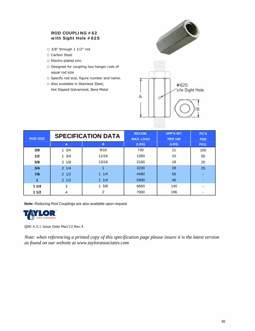
ROD COUPLING #62with Sight Hole #62S
□ 3/8" through 1 1/2" rod
□ Carbon Steel
□ Electro-plated zinc
□ Designed for coupling two hanger rods of
equal rod size
□ Specify rod size, figure number and name.
□ Also available in Stainless Steel,
Hot Dipped Galvanized, Bare Metal
PC'SPER
A PKG.
3/8 1 3/4 1001/2 1 3/4 505/8 2 1/8 253/4 2 1/4 257/8 2 1/2 -1 2 1/2 -
1 1/4 3 -1 1/2 4 -
Note: Reducing Rod Couplings are also available upon request
QWI 4.3.1 Issue Date Mar/13 Rev.4
Note: when referencing a printed copy of this specification page please insure it is the latest version as found on our website at www.taylorassociates.com
1 5/8 6660 1402 7000 196
1 1/4 4480 581 1/4 5900 46
1 3230
11
281810
73011/16 135013/16 2160
ROD SIZE
9/16B (LBS)
APP'X WT.PER 100SPECIFICATION DATA RECOM.
MAX. LOAD(LBS)
95
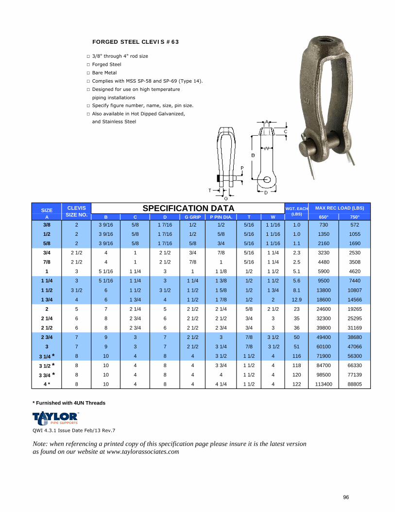
FORGED STEEL CLEVIS #63
□ 3/8" through 4" rod size
□ Forged Steel
□ Bare Metal
□ Complies with MSS SP-58 and SP-69 (Type 14).
□ Designed for use on high temperature
piping installations
□ Specify figure number, name, size, pin size.
□ Also available in Hot Dipped Galvanized,
and Stainless Steel
SIZEA B C D G GRIP P PIN DIA. T W 650° 750°
1 1/2 3 1/2 6 1 1/2 3 1/2 1 1/2 1 5/8 1/2 1 3/4 8.1 13800 10807
1 3/4 4 6 1 3/4 4 1 1/2 1 7/8 1/2 2 12.9 18600 14566
2 5 7 2 1/4 5 2 1/2 2 1/4 5/8 2 1/2 23 24600 19265
2 1/4 6 8 2 3/4 6 2 1/2 2 1/2 3/4 3 35 32300 25295
2 1/2 6 8 2 3/4 6 2 1/2 2 3/4 3/4 3 36 39800 31169
2 3/4 7 9 3 7 2 1/2 3 7/8 3 1/2 50 49400 38680
3 7 9 3 7 2 1/2 3 1/4 7/8 3 1/2 51 60100 47066
3 1/4 * 8 10 4 8 4 3 1/2 1 1/2 4 116 71900 56300
3 1/2 * 8 10 4 8 4 3 3/4 1 1/2 4 118 84700 66330
3 3/4 * 8 10 4 8 4 4 1 1/2 4 120 98500 77139
4 * 8 10 4 8 4 4 1/4 1 1/2 4 122 113400 88805
* Furnished with 4UN Threads
QWI 4.3.1 Issue Date Feb/13 Rev.7
Note: when referencing a printed copy of this specification page please insure it is the latest version as found on our website at www.taylorassociates.com
2.5
CLEVIS SIZE NO.
5/16 1 1/44 1 2 1/2 7/8
1.0
3 9/16
MAX REC LOAD (LBS)WGT. EACH (LBS)
SPECIFICATION DATA
5/16 1 1/4
5/16
1 1/16
1 1/16
1 1/16
3/4
5 1/16
7/84 1 2 1/2
1
1 1/4 3 5 1/16 1 1/4 3 1 1/4 1 3/8 1/2
2.3
1/2 1/23/8 2 3 9/16 5/8
5/8
5/16
5/16
2530
16902160
572730
10551350
3230
1.0
1 7/16
1 7/16
1 7/16
1.1
1/2 5/8
5/8 3/4
5/81/2 2
7/8 2 1/2
3/4 2 1/2
5/8 2 3 9/16
1 3 1 1/4
35084480
3 1 1 1/8 5900 4620
7440
1/2 1 1/2
5.6
5.1
1 1/2 9500
96
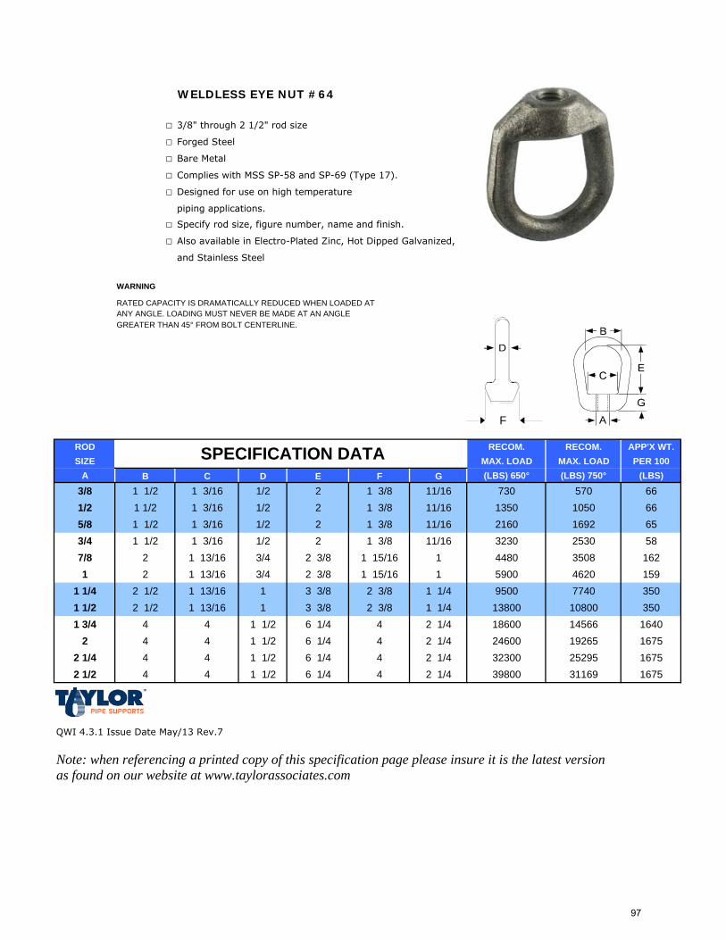
WELDLESS EYE NUT #64
□ 3/8" through 2 1/2" rod size
□ Forged Steel
□ Bare Metal
□ Complies with MSS SP-58 and SP-69 (Type 17).
□ Designed for use on high temperature
piping applications.
□ Specify rod size, figure number, name and finish.
□ Also available in Electro-Plated Zinc, Hot Dipped Galvanized,
and Stainless Steel
RATED CAPACITY IS DRAMATICALLY REDUCED WHEN LOADED AT ANY ANGLE. LOADING MUST NEVER BE MADE AT AN ANGLEGREATER THAN 45° FROM BOLT CENTERLINE.
ROD RECOM. RECOM. APP'X WT.SIZE MAX. LOAD MAX. LOAD PER 100
A B C D E F G (LBS) 650° (LBS) 750° (LBS)
3/8 1 1/2 1 3/16 1/2 2 1 3/8 11/16 730 570 661/2 1 1/2 1 3/16 1/2 2 1 3/8 11/16 1350 1050 665/8 1 1/2 1 3/16 1/2 2 1 3/8 11/16 2160 1692 653/4 1 1/2 1 3/16 1/2 2 1 3/8 11/16 3230 2530 587/8 2 1 13/16 3/4 2 3/8 1 15/16 1 4480 3508 1621 2 1 13/16 3/4 2 3/8 1 15/16 1 5900 4620 159
1 1/4 2 1/2 1 13/16 1 3 3/8 2 3/8 1 1/4 9500 7740 3501 1/2 2 1/2 1 13/16 1 3 3/8 2 3/8 1 1/4 13800 10800 3501 3/4 4 4 1 1/2 6 1/4 4 2 1/4 18600 14566 1640
2 4 4 1 1/2 6 1/4 4 2 1/4 24600 19265 16752 1/4 4 4 1 1/2 6 1/4 4 2 1/4 32300 25295 16752 1/2 4 4 1 1/2 6 1/4 4 2 1/4 39800 31169 1675
QWI 4.3.1 Issue Date May/13 Rev.7
Note: when referencing a printed copy of this specification page please insure it is the latest version as found on our website at www.taylorassociates.com
SPECIFICATION DATA
WARNING
F
97
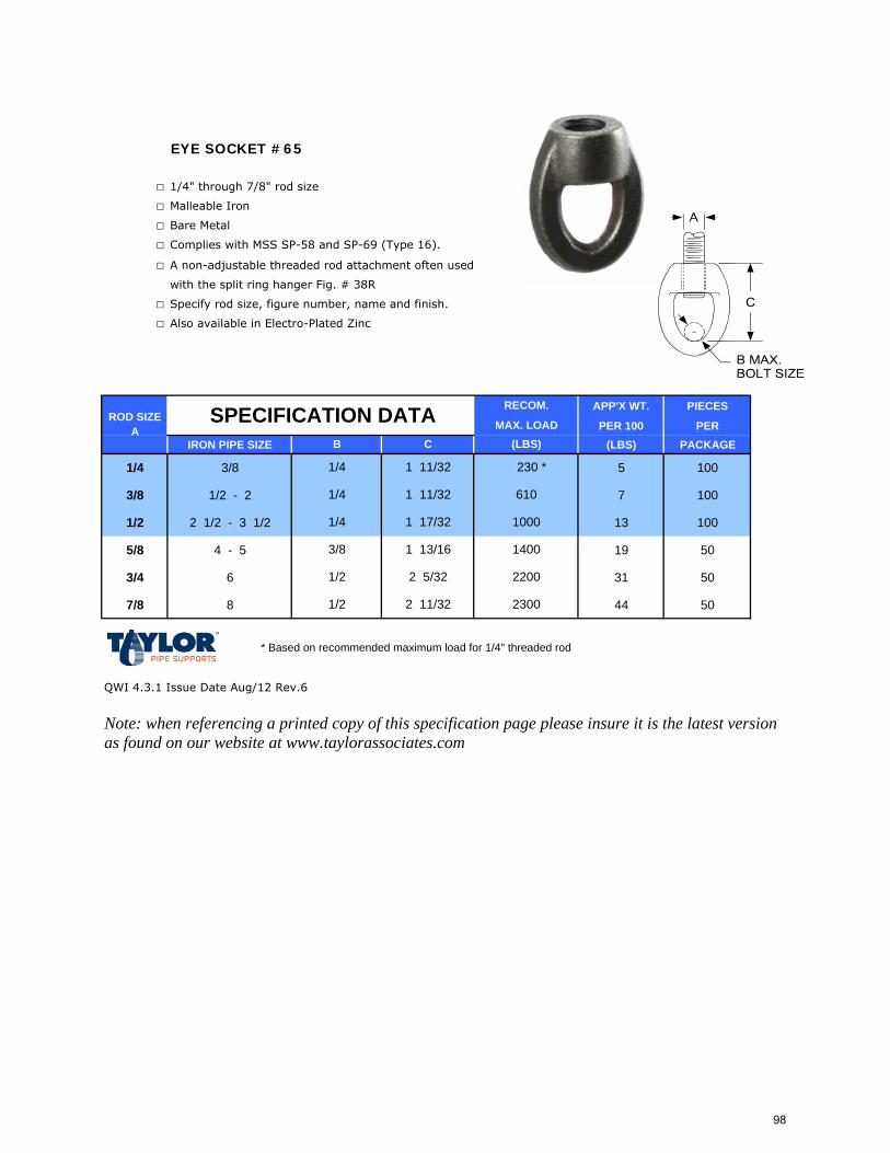
EYE SOCKET #65
□ 1/4" through 7/8" rod size
□ Malleable Iron
□ Bare Metal
□ Complies with MSS SP-58 and SP-69 (Type 16).
□ A non-adjustable threaded rod attachment often used
with the split ring hanger Fig. # 38R
□ Specify rod size, figure number, name and finish.
□ Also available in Electro-Plated Zinc
APP'X WT. PIECES
PER 100 PER IRON PIPE SIZE (LBS) PACKAGE
1/4 3/8 5 100
3/8 1/2 - 2 7 100
1/2 2 1/2 - 3 1/2 13 100
5/8 4 - 5 19 50
3/4 6 31 50
7/8 8 44 50
* Based on recommended maximum load for 1/4" threaded rod
QWI 4.3.1 Issue Date Aug/12 Rev.6
Note: when referencing a printed copy of this specification page please insure it is the latest version as found on our website at www.taylorassociates.com
ROD SIZE A
1/4
B
SPECIFICATION DATAC
1 11/32
1 11/32
RECOM.
MAX. LOAD (LBS)
230 *
1/2 2 11/32 2300
1/2 2 5/32
1000
1/4
2200
1400
610
3/8 1 13/16
1/4 1 17/32
98
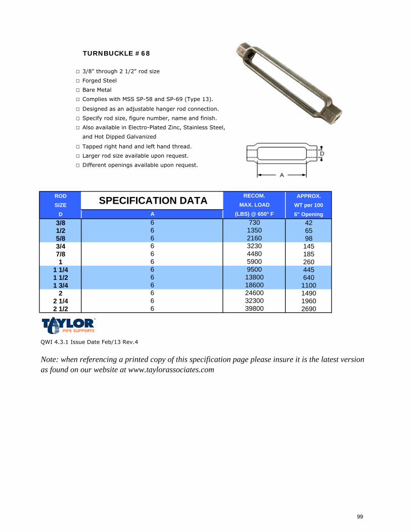
TURNBUCKLE #68
□ 3/8" through 2 1/2" rod size
□ Forged Steel
□ Bare Metal
□ Complies with MSS SP-58 and SP-69 (Type 13).
□ Designed as an adjustable hanger rod connection.
□ Specify rod size, figure number, name and finish.
□ Also available in Electro-Plated Zinc, Stainless Steel,
and Hot Dipped Galvanized
□ Tapped right hand and left hand thread.
□ Larger rod size available upon request.
□ Different openings available upon request.
ROD APPROX.SIZE WT per 100
D 6" Opening3/8 421/2 655/8 983/4 1457/8 1851 260
1 1/4 4451 1/2 6401 3/4 1100
2 14902 1/4 19602 1/2 2690
QWI 4.3.1 Issue Date Feb/13 Rev.4
Note: when referencing a printed copy of this specification page please insure it is the latest version as found on our website at www.taylorassociates.com
13800
59009500
1350216032304480
(LBS) @ 650° F
SPECIFICATION DATAA
6
666
RECOM.
730
MAX. LOAD
6
66
6
6 186006 246006 323006 39800
99
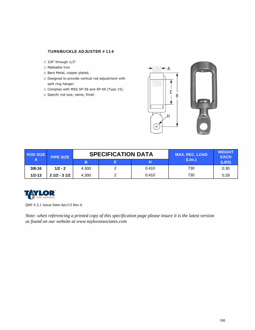
TURNBUCKLE ADJUSTER #114
□ 3/8" through 1/2"
□ Malleable Iron
□ Bare Metal, copper plated.
□ Designed to provide vertical rod adjustment with
split ring hanger.
□ Complies with MSS SP-58 and SP-69 (Type 15).
□ Specify rod size, name, finish
WEIGHT EACH
B (LBS)3/8-16 1/2 - 2 4.300 0.30
1/2-13 2 1/2 - 3 1/2 4.300 0.28
QWI 4.3.1 Issue Date Apr/13 Rev.0
Note: when referencing a printed copy of this specification page please insure it is the latest version as found on our website at www.taylorassociates.com
MAX. REC. LOAD (Lbs.)
730
730
ROD SIZE A E
PIPE SIZE SPECIFICATION DATAH
0.410
0.410
2
2
100
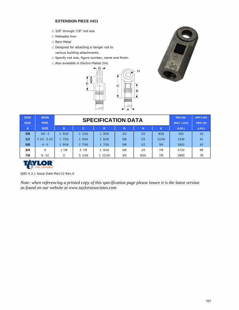
EXTENSION PIECE #411
□ 3/8" through 7/8" rod size
□ Malleable Iron
□ Bare Metal
□ Designed for attaching a hanger rod to
various building attachments.
□ Specify rod size, figure number, name and finish.
□ Also available in Electro-Plated Zinc
ROD IRON RECOM. APP'X WT.
SIZE PIPE MAX. LOAD PER 100
A SIZE B C E G H K (LBS.) (LBS.)
3/8 3/4 - 2 1 5/16 2 1/16 1 3/16 1/2 1/2 9/16 610 19
1/2 2 1/2 - 3 1/2 1 7/16 2 5/16 1 5/16 5/8 1/2 11/16 1130 41
5/8 4 - 5 1 9/16 2 7/16 1 7/16 5/8 1/2 3/4 1810 42
3/4 6 1 7/8 2 7/8 1 9/16 5/8 1/2 7/8 2710 68
7/8 8 - 12 2 3 1/16 1 11/16 3/4 9/16 7/8 2950 78
QWI 4.3.1 Issue Date Mar/12 Rev.4
Note: when referencing a printed copy of this specification page please insure it is the latest version as found on our website at www.taylorassociates.com
SPECIFICATION DATA
101
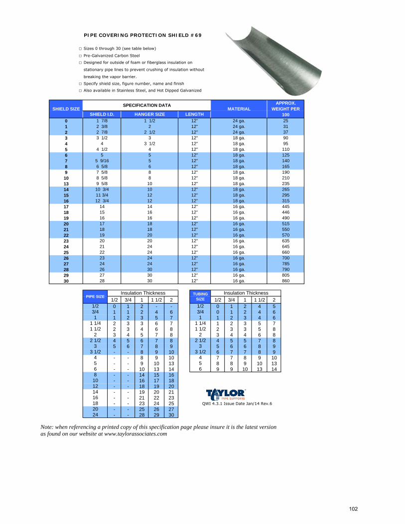
PIPE COVERING PROTECTION SHIELD #69
□ Sizes 0 through 30 (see table below)
□ Pre-Galvanized Carbon Steel
□ Designed for outside of foam or fiberglass insulation on
stationary pipe lines to prevent crushing of insulation without
breaking the vapor barrier.
□ Specify shield size, figure number, name and finish
□ Also available in Stainless Steel, and Hot Dipped Galvanized
0123456789
10131415161718192021222324252627282930
1/2 3/4 1 1 1/2 2 1/2 3/4 1 1 1/2 20 1 2 - - 0 1 2 4 51 1 2 4 6 0 1 2 4 61 2 3 5 7 1 2 3 4 62 3 3 6 7 1 2 3 5 72 3 4 6 8 2 3 3 5 83 4 5 7 8 3 4 4 6 84 5 6 7 8 4 5 5 7 85 6 7 8 9 5 6 6 8 9- - 8 9 10 6 7 7 8 9- - 8 9 10 7 7 8 9 10- - 9 10 13 8 8 9 10 13- - 10 13 14 9 9 10 13 14- - 14 15 16- - 16 17 18- - 18 19 20- - 19 20 21- - 21 22 23- - 23 24 25 QWI 4.3.1 Issue Date Jan/14 Rev.6
- - 25 26 27- - 28 29 30
Note: when referencing a printed copy of this specification page please insure it is the latest version as found on our website at www.taylorassociates.com
860
12"12"12"12"12"12"12"12"12"
79027 30 16 ga. 80526 30 16 ga.
66023 24 16 ga. 70022 24
16 ga.
PIPE SIZE TUBING SIZE
Insulation Thickness
28 30 12" 16 ga.
5
19 20 16 ga.
16 ga.21 24 16 ga.20 20
3 1/2456
1 1/22
2 1/23
2024
1/23/41
1 1/41 1/2
22 1/2
3
12141618
810
1
Insulation Thickness
1/23/4
3 1/24
6
1 1/4
1255 9/16 5 12" 18 ga. 140
5 5 12" 18 ga.
954 1/2 4 12" 18 ga. 110
4 3 1/2 12" 18 ga.
253137
3 1/2 3 12" 18 ga. 90
12"12"12"
24 ga.24 ga.24 ga.
1 7/82 3/82 7/8
1 1/22
2 1/2
SPECIFICATION DATAMATERIAL
APPROX. WEIGHT PER
100SHIELD I.D. HANGER SIZE LENGTHSHIELD SIZE
1657 5/8 8 12" 18 ga. 190
12" 18 ga.6 5/8 6
2109 5/8 10 12" 18 ga. 235
12" 18 ga.8 5/8 8
26511 3/4 12 12" 18 ga. 295
12" 18 ga.10 3/4 10
31514 14 16 ga. 445
12" 18 ga.12 3/4 1212"
16 ga.550570
16 ga. 785
16 ga.
635645
515
4461615 16 16 ga.
16 49016 ga.12"
24
12"
24
18 1812"1817
102
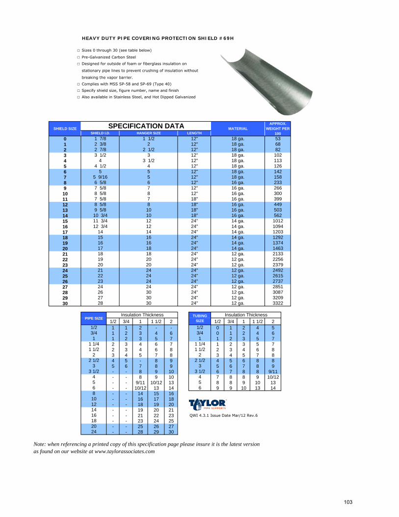
HEAVY DUTY PIPE COVERING PROTECTION SHIELD #69H
□ Sizes 0 through 30 (see table below)
□ Pre-Galvanized Carbon Steel
□ Designed for outside of foam or fiberglass insulation on
stationary pipe lines to prevent crushing of insulation without
breaking the vapor barrier.
□ Complies with MSS SP-58 and SP-69 (Type 40)
□ Specify shield size, figure number, name and finish
□ Also available in Stainless Steel, and Hot Dipped Galvanized
0123456789101112131415161718192021222324252627282930
1/2 3/4 1 1 1/2 2 1/2 3/4 1 1 1/2 21 1 2 - - 0 1 2 4 51 2 3 4 6 0 1 2 4 61 2 3 5 7 1 2 3 5 72 3 4 6 7 1 2 3 5 72 3 4 6 8 2 3 4 6 83 4 5 7 8 3 4 5 7 84 5 - 8 9 4 5 6 8 85 6 7 8 9 5 6 7 8 9- - 8 9 10 6 7 8 8 9/11- - 8 9 10 7 8 8 9 10/12- - 9/11 10/12 13 8 8 9 10 13- - 10/12 13 14 9 9 10 13 14- - 14 15 16- - 16 17 18- - 18 19 20- - 19 20 21- - 21 22 23 QWI 4.3.1 Issue Date Mar/12 Rev.6
- - 23 24 25- - 25 26 27- - 28 29 30
Note: when referencing a printed copy of this specification page please insure it is the latest version as found on our website at www.taylorassociates.com
24"
24"24"24"24"
273724 12 ga. 285123 24 12 ga.24"
PIPE SIZE TUBING SIZE
Insulation Thickness
237921 24 12 ga. 249220 20
213319 20 12 ga. 225618 18 12 ga.24"17 18 14 ga.16 16 14 ga.24"
24"
24 12 ga. 2615
5
24" 12 ga. 3209
24"
332212 ga.
3 1/2456
1 1/22
2 1/23
2024
1/23/41
1 1/41 1/2
22 1/2
3
12141618
810
1
Insulation Thickness
1/23/4
3 1/24
6
1 1/4
1425 9/16 5 12" 158
5 5 12"18 ga.
1134 1/2 4 12" 126
4 3 1/2 12"
536882
3 1/2 3 12" 102
12"12"12"
SHIELD SIZE
18 ga.18 ga.18 ga.
1 7/82 3/82 7/8
1 1/22
2 1/2
SPECIFICATION DATA MATERIALAPPROX.
WEIGHT PER 100SHIELD I.D. HANGER SIZE LENGTH
2337 5/8 7 12" 16 ga. 266
12" 16 ga.6 5/8 6
3007 5/8 7 18" 16 ga. 399
12" 16 ga.8 5/8 8
4499 5/8 10 18" 16 ga. 503
18" 16 ga.8 5/8 8
56211 3/4 12 14 ga. 1012
18" 16 ga.10 3/4 1024"
1615
109414
12 3/4 12 14 ga.14 120324"
14 ga.13741463
24" 12 ga. 3087
12 ga.
18 ga.18 ga.18 ga.18 ga.
24"
129224"14 ga.
22
26 3027 30
3028
24
103
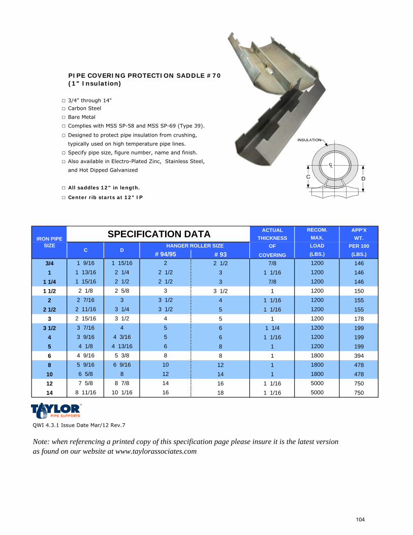
PIPE COVERING PROTECTION SADDLE #70(1" Insulation)
□ 3/4" through 14"
□ Carbon Steel
□ Bare Metal
□ Complies with MSS SP-58 and MSS SP-69 (Type 39).
□ Designed to protect pipe insulation from crushing,
typically used on high temperature pipe lines.
□ Specify pipe size, figure number, name and finish.
□ Also available in Electro-Plated Zinc, Stainless Steel,
and Hot Dipped Galvanized
□ All saddles 12" in length.
□ Center rib starts at 12" IP
ACTUAL APP'XTHICKNESS WT.
OF PER 100# 93 COVERING (LBS.)
3/4 2 1/2 7/8 1461 3 1 1/16 146
1 1/4 3 7/8 1461 1/2 3 1/2 1 150
2 4 1 1/16 1552 1/2 5 1 1/16 155
3 5 1 1783 1/2 6 1 1/4 199
4 6 1 1/16 1995 8 1 1996 8 1 3948 12 1 47810 14 1 47812 16 1 1/16 75014 18 1 1/16 750
QWI 4.3.1 Issue Date Mar/12 Rev.7
Note: when referencing a printed copy of this specification page please insure it is the latest version as found on our website at www.taylorassociates.com
1200
1200
IRON PIPE SIZE HANGER ROLLER SIZE
# 94/95
2 1/2
C D
2 1/2
SPECIFICATION DATA
21 15/16
RECOM.MAX.
(LBS.)LOAD
1800
12001200
4
86 12005 12005
3 9/16 4 3/163 7/162 15/16
43 1/2
4 9/16 5 3/84 1/8 4 13/16
1800
2 1/4 12002 1/2
3 1200
1200
3 1/22 5/8 3
1800
1 9/16
1 15/16
2 7/162 11/16
1 13/16
2 1/8
1200
3 1/4 3 1/2
50005000
5 9/16 6 9/16 106 5/8 8 127 5/8 8 7/8 14
8 11/16 10 1/16 16
104

PIPE COVERING PROTECTION SADDLE #71(1 1/2" Insulation)
□ 3/4" through 20"
□ Carbon Steel
□ Bare Metal
□ Complies with MSS SP-58 and MSS SP-69 (Type 39).
□ Designed to protect pipe insulation from crushing,
typically used on high temperature pipe lines.
□ Specify pipe size, figure number, name and finish.
□ Also available in Electro-Plated Zinc, Stainless Steel,
and Hot Dipped Galvanized
□ All saddles 12" in length.
□ Center rib starts at 12" IP
ACTUAL APP'XTHICKNESS WT.
OF PER 100
# 93 COVERING (LBS.)
3/4 3 1/2 1 7/16 1991 4 1 9/16 199
1 1/4 5 1 5/8 1991 1/2 5 1 1/2 199
2 5 1 9/16 2202 1/2 6 1 7/8 220
3 6 1 9/16 2203 1/2 8 1 13/16 241
4 8 1 9/16 2415 8 1 1/2 2416 10 1 1/2 4588 12 1 1/2 58610 14 1 9/16 58612 16 1 1/2 83014 18 1 1/2 83016 20 1 1/2 92618 -- 1 1/2 99020 -- 1 1/2 1054
QWI 4.3.1 Issue Date Mar/12 Rev.6
Note: when referencing a printed copy of this specification page please insure it is the latest version as found on our website at www.taylorassociates.com
4 1/8
2 11/16 3 1/4 3 1/242 7/8
3 3/4
120033
2 5/8
12001200
4 11/164 4 11/16
3 1/2
1200120012001800
4 1/2 5 5/16
SPECIFICATION DATA
4 3/16
3 3/32
3 1/25566
6 7 1/85 1/16 5 7/8
127 1/4 8 5/16 1800148 1/16 9 5/8 5000168 7/8 10 3/16 5000189 7/8 11 3/8 50002010 7/8 12 1/2 50002411 3/4 13 11/16 7200
18008 18008 1800
180010
3 1/2
RECOM.MAX.
(LBS.)LOADHANGER ROLLER SIZE
# 94/951200
3 1/8
C DIRON PIPE SIZE
2 15/162 1/8
2 9/162 7/16
105

PIPE COVERING PROTECTION SADDLE #72(2" Insulation)
□ 3/4" through 20"
□ Carbon Steel
□ Bare Metal
□ Complies with MSS SP-58 and MSS SP-69 (Type 39).
□ Designed to protect pipe insulation from crushing,
typically used on high temperature pipe lines.
□ Specify pipe size, figure number, name and finish.
□ Also available in Electro-Plated Zinc, Stainless Steel,
and Hot Dipped Galvanized
□ All saddles 12" in length.
□ Center rib starts at 12" IP
ACTUAL APP'XTHICKNESS WT.
OF PER 100# 93 COVERING (LBS.)
3/4 5 2 1/16 2631 5 2 1/8 263
1 1/4 5 2 1/16 2631 1/2 6 2 5/16 284
2 6 2 1/8 2842 1/2 8 2 5/16 284
3 8 2 1/16 3283 1/2 8 2 1/4 328
4 8 2 1/16 3285 10 2 3286 10 2 5868 12 2 61810 16 2 1/16 61812 18 2 1/16 99014 18 2 99016 20 2 105418 -- 2 111820 -- 2 1181
QWI 4.3.1 Issue Date Mar/12 Rev.6
Note: when referencing a printed copy of this specification page please insure it is the latest version as found on our website at www.taylorassociates.com
4 5/8
3 7/16 4 1/8 553 11/16
3 15/16
120044
3 3/8 1200
18001200
5 1/24 5 3/16
4 1/8
1800180018001800
4 15/16 5 7/8
SPECIFICATION DATA
4 7/8
4 11/16
4 3/86688
6 1/2 7 5/85 1/2 6 1/2
147 5/8 9 1/16 1800168 13/16 10 3/16 5000169 1/4 10 3/4 50001810 1/4 11 7/8 50002011 1/2 13 1/16 72002412 5/16 14 1/4 7200
8 180010 1800
IRON PIPE SIZE
180012
5
RECOM.MAX.
(LBS.)LOADHANGER ROLLER SIZE
1800
3 11/16
C D# 94/95
3 1/22 3/4
3 1/162 7/8
106
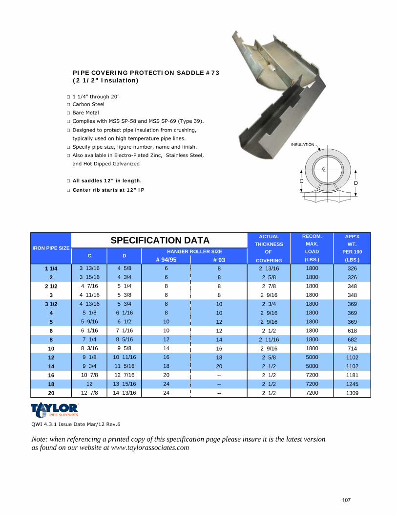
PIPE COVERING PROTECTION SADDLE #73(2 1/2" Insulation)
□ 1 1/4" through 20"
□ Carbon Steel
□ Bare Metal
□ Complies with MSS SP-58 and MSS SP-69 (Type 39).
□ Designed to protect pipe insulation from crushing,
typically used on high temperature pipe lines.
□ Specify pipe size, figure number, name and finish.
□ Also available in Electro-Plated Zinc, Stainless Steel,
and Hot Dipped Galvanized
□ All saddles 12" in length.
□ Center rib starts at 12" IP
ACTUAL APP'XTHICKNESS WT.
OF PER 100# 93 COVERING (LBS.)
1 1/4 8 2 13/16 3262 8 2 5/8 326
2 1/2 8 2 7/8 3483 8 2 9/16 348
3 1/2 10 2 3/4 3694 10 2 9/16 3695 12 2 9/16 3696 12 2 1/2 6188 14 2 11/16 68210 16 2 9/16 71412 18 2 5/8 110214 20 2 1/2 110216 -- 2 1/2 118118 -- 2 1/2 124520 -- 2 1/2 1309
QWI 4.3.1 Issue Date Mar/12 Rev.6
Note: when referencing a printed copy of this specification page please insure it is the latest version as found on our website at www.taylorassociates.com
IRON PIPE SIZE
RECOM.MAX.
(LBS.)LOADHANGER ROLLER SIZE
# 94/95
180012
C D
10 180010 1800
8 18008 1800
1800
68 1800
1800
2412 7/8 14 13/16 72002412 13 15/16 7200
72002010 7/8 12 7/165000189 3/4 11 5/165000169 1/8 10 11/161800148 3/16 9 5/8
7 1/4 8 5/166 1/16 7 1/165 9/16 6 1/2
SPECIFICATION DATA
5 3/8
5 1/8 6 1/164 13/16 5 3/44 11/16 8
1800
5 1/4
3 13/16 4 5/8 64 3/43 15/16
4 7/16
107

PIPE COVERING PROTECTION SADDLE #74(3" Insulation)
□ 2" through 20"
□ Carbon Steel
□ Bare Metal
□ Complies with MSS SP-58 and MSS SP-69 (Type 39).
□ Designed to protect pipe insulation from crushing,
typically used on high temperature pipe lines.
□ Specify pipe size, figure number, name and finish.
□ Also available in Electro-Plated Zinc, Stainless Steel,
and Hot Dipped Galvanized
□ All saddles 12" in length.
□ Center rib starts at 12" IP
ACTUAL APP'XTHICKNESS WT.
OF PER 100# 93 COVERING (LBS.)
2 8 3 1/8 3902 1/2 10 3 3/8 390
3 10 3 1/16 4333 1/2 10 3 5/16 433
4 10 3 1/16 4335 12 3 1/16 4336 12 3 8098 16 3 1/8 80910 18 3 1/16 87312 20 3 1/16 122914 20 3 122916 -- 3 130918 -- 3 137320 -- 3 1437
QWI 4.3.1 Issue Date Mar/12 Rev.6
Note: when referencing a printed copy of this specification page please insure it is the latest version as found on our website at www.taylorassociates.com
10
8
5
4 11/164 15/16
5 1/25 3/4
1800
18008
6 1/2
180010 1800
10 18006 7/16
5 9/166 1/8 7 1/16
5 15/165 1/2
7 5/8 9 1/86 9/16 7 5/8
168 7/8 10 1/4 1800189 11/16 11 5/16 50001810 1/4 11 7/8 50002411 3/16 13 1/8 72002412 5/16 14 1/4 72002413 1/2 15 1/2 7200
10 180012
1800141800
RECOM.MAX.
(LBS.)LOAD
IRON PIPE SIZEHANGER ROLLER SIZE
# 94/95C D
SPECIFICATION DATA
108

PIPE COVERING PROTECTION SADDLE #75(4" Insulation)
□ 4" through 20"
□ Carbon Steel
□ Bare Metal
□ Complies with MSS SP-58 and MSS SP-69 (Type 39).
□ Designed to protect pipe insulation from crushing,
typically used on high temperature pipe lines.
□ Specify pipe size, figure number, name and finish.
□ Also available in Electro-Plated Zinc, Stainless Steel,
and Hot Dipped Galvanized
□ All saddles 12" in length.
□ Center rib starts at 12" IP
ACTUAL APP'XTHICKNESS WT.
OF PER 100# 93 COVERING (LBS.)
4 14 4 1/16 6245 14 4 3/16 6246 16 4 1/8 10018 18 4 1/8 100110 20 4 1/16 109712 -- 4 1/8 148514 -- 4 148516 -- 4 156418 -- 4 162820 -- 4 1692
QWI 4.3.1 Issue Date Mar/12 Rev.6
Note: when referencing a printed copy of this specification page please insure it is the latest version as found on our website at www.taylorassociates.com
RECOM.MAX.
(LBS.)LOAD
8 11/16 10 1/87 5/8 9 1/8
C DHANGER ROLLER SIZE
180014 180016
1800
24 720020 500020 5000
1800181800
3014 3/16 16 5/8 720013 1/2 15 7/16 72002412 5/16 14 3/1611 7/16 13 1/8
10 13/16 12 3/89 11/16 11 5/16
IRON PIPE SIZE
# 94/95
8 1/4
SPECIFICATION DATA
6 9/16 7 11/16 12127 3/16
109
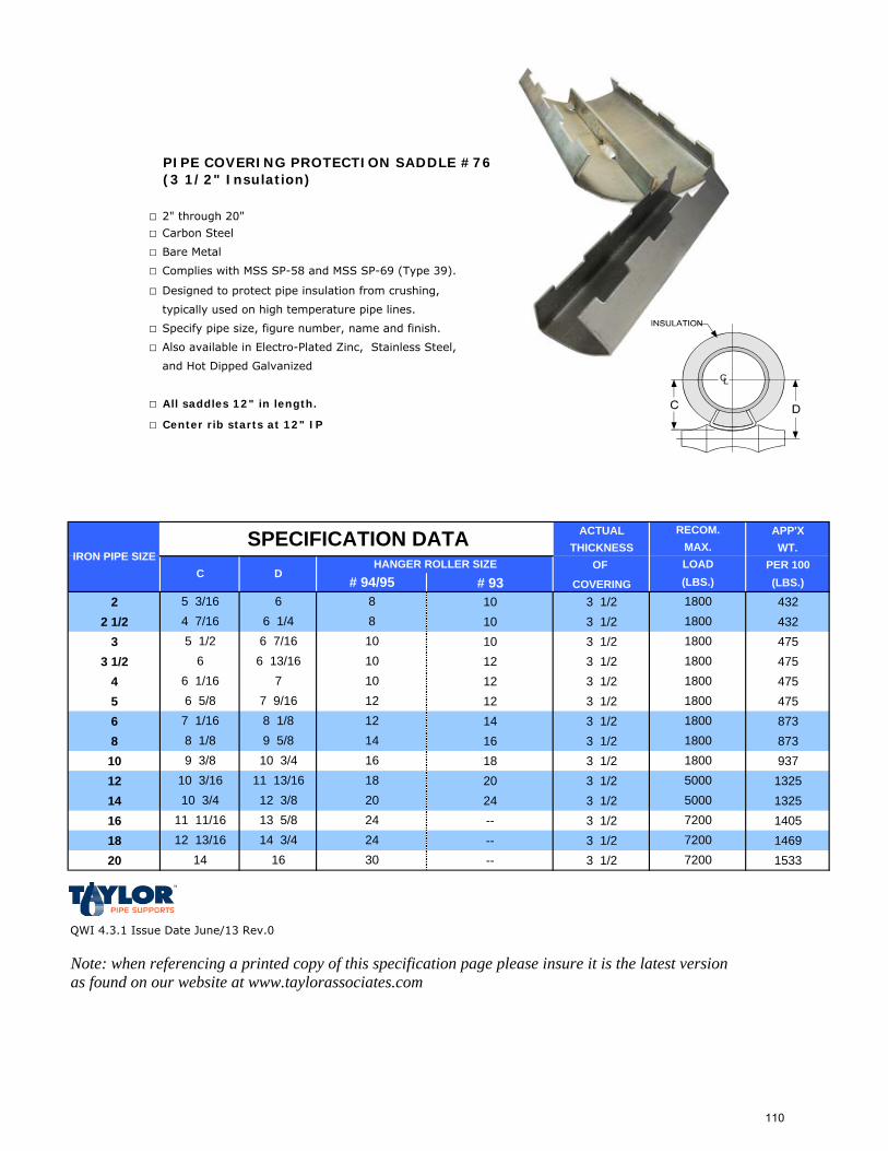
PIPE COVERING PROTECTION SADDLE #76(3 1/2" Insulation)
□ 2" through 20"
□ Carbon Steel
□ Bare Metal
□ Complies with MSS SP-58 and MSS SP-69 (Type 39).
□ Designed to protect pipe insulation from crushing,
typically used on high temperature pipe lines.
□ Specify pipe size, figure number, name and finish.
□ Also available in Electro-Plated Zinc, Stainless Steel,
and Hot Dipped Galvanized
□ All saddles 12" in length.
□ Center rib starts at 12" IP
ACTUAL APP'XTHICKNESS WT.
OF PER 100# 93 COVERING (LBS.)
2 10 3 1/2 4322 1/2 10 3 1/2 432
3 10 3 1/2 4753 1/2 12 3 1/2 475
4 12 3 1/2 4755 12 3 1/2 4756 14 3 1/2 8738 16 3 1/2 87310 18 3 1/2 93712 20 3 1/2 132514 24 3 1/2 132516 -- 3 1/2 140518 -- 3 1/2 146920 -- 3 1/2 1533
QWI 4.3.1 Issue Date June/13 Rev.0
Note: when referencing a printed copy of this specification page please insure it is the latest version as found on our website at www.taylorassociates.com
IRON PIPE SIZEHANGER ROLLER SIZE
# 94/95C D
SPECIFICATION DATA RECOM.MAX.
(LBS.)LOAD
12 180012
1800141800
3014 16 72002412 13/16 14 3/4 72002411 11/16 13 5/8 72002010 3/4 12 3/8 50001810 3/16 11 13/16 5000169 3/8 10 3/4 1800
8 1/8 9 5/87 1/16 8 1/8
6 1/166 5/8 7 9/16
6 7/166 1800
18008
7
180010 1800
10 18006 13/16 10
8
5 1/2
5 3/164 7/16
66 1/4
110
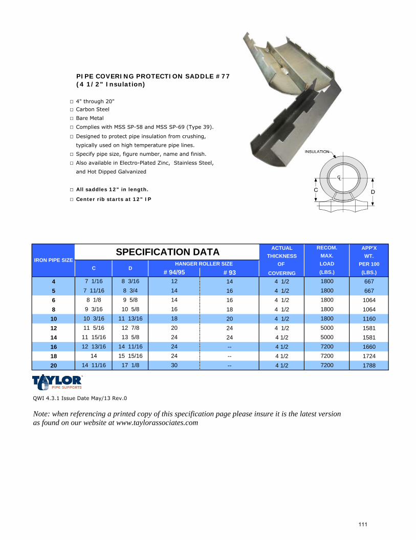
PIPE COVERING PROTECTION SADDLE #77(4 1/2" Insulation)
□ 4" through 20"
□ Carbon Steel
□ Bare Metal
□ Complies with MSS SP-58 and MSS SP-69 (Type 39).
□ Designed to protect pipe insulation from crushing,
typically used on high temperature pipe lines.
□ Specify pipe size, figure number, name and finish.
□ Also available in Electro-Plated Zinc, Stainless Steel,
and Hot Dipped Galvanized
□ All saddles 12" in length.
□ Center rib starts at 12" IP
ACTUAL APP'XTHICKNESS WT.
OF PER 100# 93 COVERING (LBS.)
4 14 4 1/2 6675 16 4 1/2 6676 16 4 1/2 10648 18 4 1/2 106410 20 4 1/2 116012 24 4 1/2 158114 24 4 1/2 158116 -- 4 1/2 166018 -- 4 1/2 172420 -- 4 1/2 1788
QWI 4.3.1 Issue Date May/13 Rev.0
Note: when referencing a printed copy of this specification page please insure it is the latest version as found on our website at www.taylorassociates.com
IRON PIPE SIZE
# 94/95
8 3/4
SPECIFICATION DATA
7 1/16 8 3/16 12147 11/16
11 5/16 12 7/810 3/16 11 13/16
12 13/16 14 11/1611 15/16 13 5/8
14 15 15/16 7200243014 11/16 17 1/8 7200
1800
24 720024 500020 5000
1800181800
180014 180016
C DHANGER ROLLER SIZE
9 3/16 10 5/88 1/8 9 5/8
RECOM.MAX.
(LBS.)LOAD
111
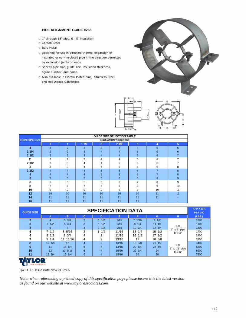
PIPE ALIGNMENT GUIDE #255
□ 1" through 16" pipe, 0 - 5" insulation.
□ Carbon Steel
□ Bare Metal
□ Designed for use in directing thermal expansion of
insulated or non-insulated pipe in the direction permitted
by expansion joints or loops.
□ Specify pipe size, guide size, insulation thickness,
figure number, and name.
□ Also available in Electro-Plated Zinc, Stainless Steel,
and Hot Dipped Galvanized
0 1 1 1/2 2 2 1/2 3 4 51 2 2 2 3 4 4 5 6
1 1/4 2 2 3 4 4 5 5 61 1/2 2 2 3 4 4 5 6 7
2 2 2 3 4 4 5 6 72 1/2 3 3 4 4 5 5 6 7
3 3 3 4 4 5 5 6 83 1/2 4 4 4 5 5 6 7 8
4 4 4 4 5 5 6 7 85 5 5 5 5 6 6 8 96 5 5 5 6 6 7 8 98 7 7 7 7 8 8 9 10
10 9 9 9 9 9 9 10 1112 10 10 10 10 10 10 11 1114 11 11 11 11 11 11 11 -16 11 11 11 11 11 11 - -
APP'X WT.PER 100
A B C D E F G H (LBS.)2 4 5 3/8 3 1 1/2 9/16 7 1/16 9 1/2 10003 4 1/2 5 3/4 3 1 1/2 9/16 8 1/4 11 1/4 11004 6 7 3 1 1/2 9/16 10 3/4 12 3/4 13005 7 1/2 8 5/16 3 1 1/2 11/16 13 1/4 15 1/2 17006 8 1/2 8 3/4 4 2 11/16 15 1/2 17 1/2 24007 9 1/4 11 11/16 4 2 13/16 17 18 3/8 31008 10 1/8 12 4 2 13/16 18 3/8 20 1/2 34009 11 13 1/4 6 4 13/16 20 1/4 22 3/8 5200
10 12 13 9/16 6 4 15/16 22 1/4 24 590011 13 3/4 15 1/4 6 4 15/16 26 28 7800
QWI 4.3.1 Issue Date Nov/13 Rev.6
Note: when referencing a printed copy of this specification page please insure it is the latest version as found on our website at www.taylorassociates.com
GUIDE SIZE
IRON PIPE SIZE
For 1" to 6" pipe
H = 4"
For 8" to 16" pipe
H = 6"
GUIDE SIZE SELECTION TABLEINSULATION THICKNESS
SPECIFICATION DATA
112
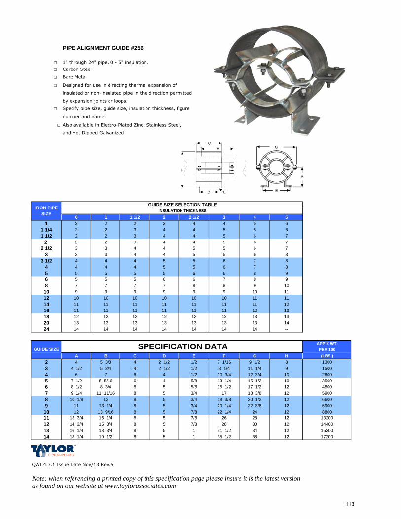
PIPE ALIGNMENT GUIDE #256
□ 1" through 24" pipe, 0 - 5" insulation.
□ Carbon Steel
□ Bare Metal
□ Designed for use in directing thermal expansion of
insulated or non-insulated pipe in the direction permitted
by expansion joints or loops.
□ Specify pipe size, guide size, insulation thickness, figure
number and name.
□ Also available in Electro-Plated Zinc, Stainless Steel,
and Hot Dipped Galvanized
0 1 1 1/2 2 2 1/2 3 4 51 2 2 2 3 4 4 5 6
1 1/4 2 2 3 4 4 5 5 61 1/2 2 2 3 4 4 5 6 7
2 2 2 3 4 4 5 6 72 1/2 3 3 4 4 5 5 6 7
3 3 3 4 4 5 5 6 83 1/2 4 4 4 5 5 6 7 8
4 4 4 4 5 5 6 7 85 5 5 5 5 6 6 8 96 5 5 5 6 6 7 8 98 7 7 7 7 8 8 9 10
10 9 9 9 9 9 9 10 1112 10 10 10 10 10 10 11 1114 11 11 11 11 11 11 11 1216 11 11 11 11 11 11 12 1318 12 12 12 12 12 12 13 1320 13 13 13 13 13 13 13 1424 14 14 14 14 14 14 14 --
APP'X WT.PER 100
A B C D E F G H (LBS.)2 4 5 3/8 4 2 1/2 1/2 7 1/16 9 1/2 8 13003 4 1/2 5 3/4 4 2 1/2 1/2 8 1/4 11 1/4 9 15004 6 7 6 4 1/2 10 3/4 12 3/4 10 26005 7 1/2 8 5/16 6 4 5/8 13 1/4 15 1/2 10 35006 8 1/2 8 3/4 8 5 5/8 15 1/2 17 1/2 12 48007 9 1/4 11 11/16 8 5 3/4 17 18 3/8 12 59008 10 1/8 12 8 5 3/4 18 3/8 20 1/2 12 66009 11 13 1/4 8 5 3/4 20 1/4 22 3/8 12 6900
10 12 13 9/16 8 5 7/8 22 1/4 24 12 880011 13 3/4 15 1/4 8 5 7/8 26 28 12 1320012 14 3/4 15 3/4 8 5 7/8 28 30 12 1440013 16 1/4 18 3/4 8 5 1 31 1/2 34 12 1530014 18 1/4 19 1/2 8 5 1 35 1/2 38 12 17200
QWI 4.3.1 Issue Date Nov/13 Rev.5
Note: when referencing a printed copy of this specification page please insure it is the latest version as found on our website at www.taylorassociates.com
SPECIFICATION DATAGUIDE SIZE
IRON PIPE SIZE
GUIDE SIZE SELECTION TABLEINSULATION THICKNESS
113
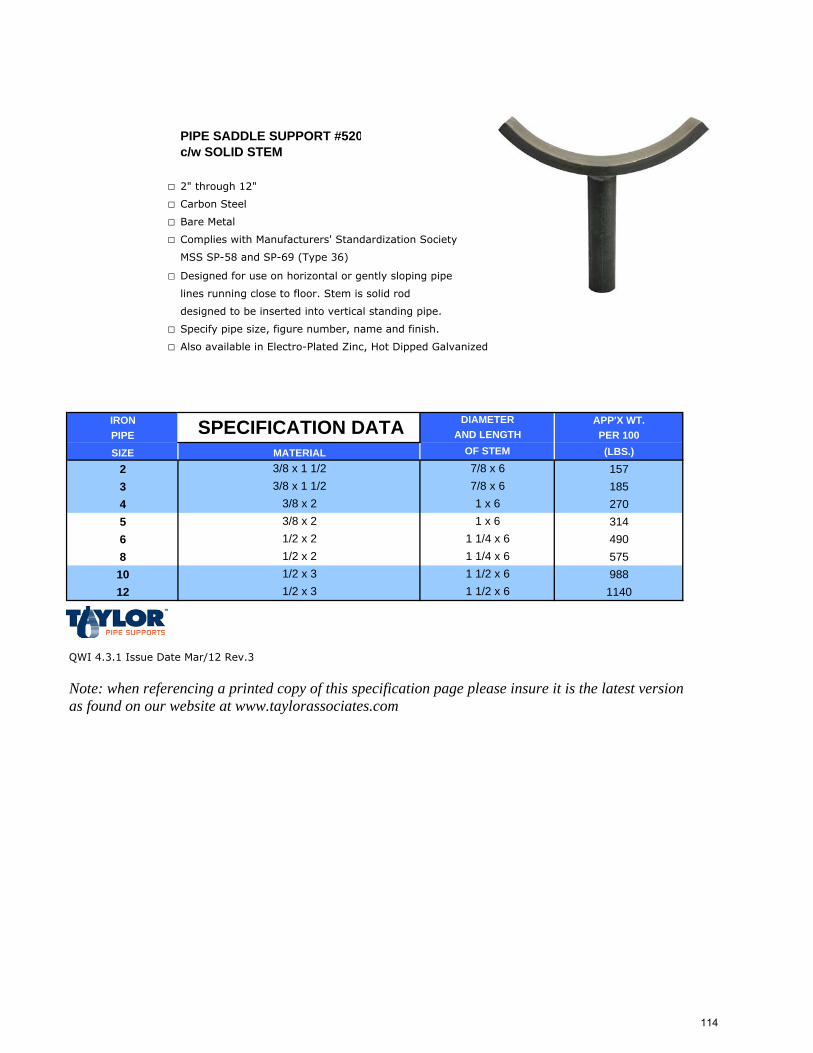
PIPE SADDLE SUPPORT #520c/w SOLID STEM
□ 2" through 12"
□ Carbon Steel
□ Bare Metal
□ Complies with Manufacturers' Standardization Society
MSS SP-58 and SP-69 (Type 36)
□ Designed for use on horizontal or gently sloping pipe
lines running close to floor. Stem is solid rod
designed to be inserted into vertical standing pipe.
□ Specify pipe size, figure number, name and finish.
□ Also available in Electro-Plated Zinc, Hot Dipped Galvanized
IRON APP'X WT.PIPE PER 100
SIZE (LBS.)
2 1573 1854 2705 3146 4908 57510 98812 1140
QWI 4.3.1 Issue Date Mar/12 Rev.3
Note: when referencing a printed copy of this specification page please insure it is the latest version as found on our website at www.taylorassociates.com
1 1/2 x 6
3/8 x 23/8 x 2
SPECIFICATION DATAMATERIAL3/8 x 1 1/23/8 x 1 1/2
DIAMETER AND LENGTH
1 1/4 x 6
OF STEM
1 1/2 x 61 1/4 x 6
7/8 x 67/8 x 6
1 x 61 x 6
1/2 x 21/2 x 21/2 x 31/2 x 3
114
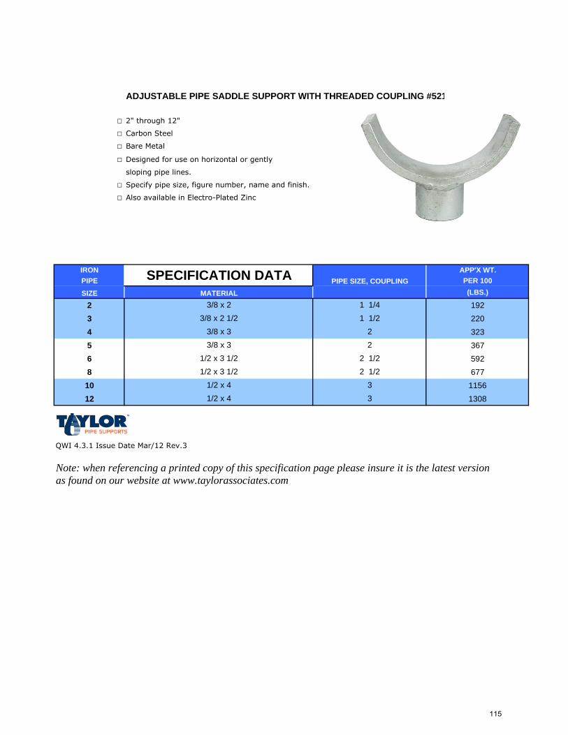
ADJUSTABLE PIPE SADDLE SUPPORT WITH THREADED COUPLING #521
□ 2" through 12"
□ Carbon Steel
□ Bare Metal
□ Designed for use on horizontal or gently
sloping pipe lines.
□ Specify pipe size, figure number, name and finish.
□ Also available in Electro-Plated Zinc
IRON APP'X WT.PIPE PER 100
SIZE (LBS.)
2 1923 2204 3235 3676 5928 67710 115612 1308
QWI 4.3.1 Issue Date Mar/12 Rev.3
Note: when referencing a printed copy of this specification page please insure it is the latest version as found on our website at www.taylorassociates.com
1/2 x 4
PIPE SIZE, COUPLING
1/2 x 3 1/21/2 x 3 1/2
1/2 x 43
SPECIFICATION DATAMATERIAL
3/8 x 23/8 x 2 1/2
32 1/2
1 1/23/8 x 33/8 x 3
1 1/4
22
2 1/2
115
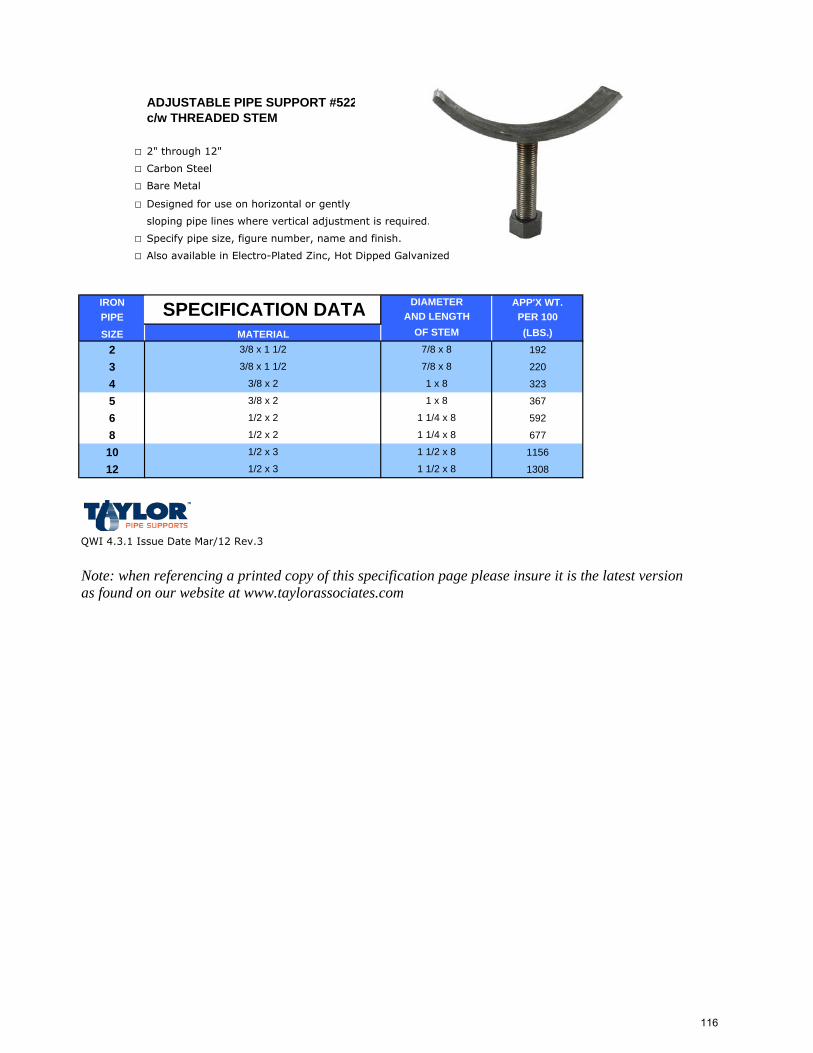
ADJUSTABLE PIPE SUPPORT #522c/w THREADED STEM
□ 2" through 12"
□ Carbon Steel
□ Bare Metal
□ Designed for use on horizontal or gently
sloping pipe lines where vertical adjustment is required.
□ Specify pipe size, figure number, name and finish.
□ Also available in Electro-Plated Zinc, Hot Dipped Galvanized
IRON APP'X WT.PIPE PER 100SIZE (LBS.)
2 192
3 220
4 323
5 367
6 592
8 677
10 1156
12 1308
QWI 4.3.1 Issue Date Mar/12 Rev.3
Note: when referencing a printed copy of this specification page please insure it is the latest version as found on our website at www.taylorassociates.com
1 1/2 x 8
3/8 x 2
3/8 x 2
SPECIFICATION DATAMATERIAL3/8 x 1 1/2
3/8 x 1 1/2
DIAMETER AND LENGTH
1 1/4 x 8
OF STEM
1 1/2 x 8
1 1/4 x 8
7/8 x 8
7/8 x 8
1 x 8
1 x 8
1/2 x 2
1/2 x 2
1/2 x 3
1/2 x 3
116
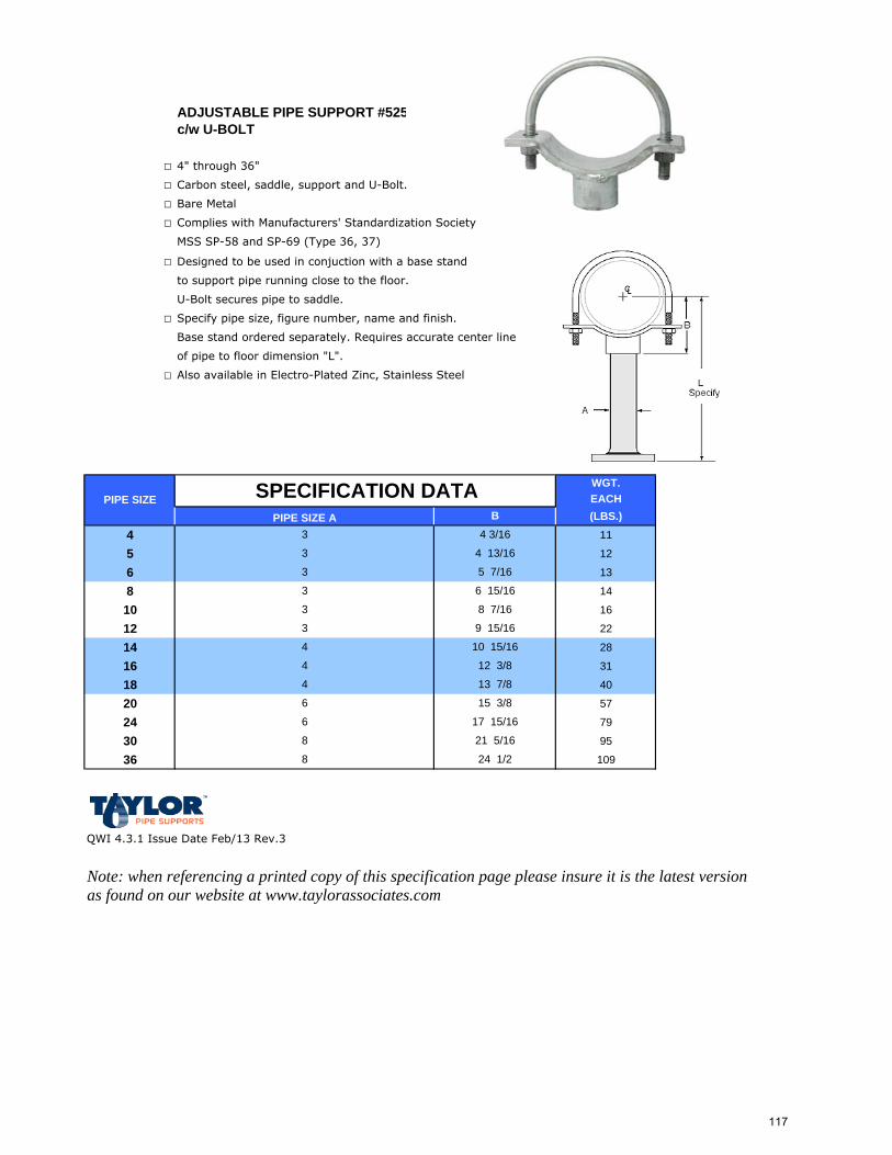
ADJUSTABLE PIPE SUPPORT #525c/w U-BOLT
□ 4" through 36"
□ Carbon steel, saddle, support and U-Bolt.
□ Bare Metal
□ Complies with Manufacturers' Standardization Society
MSS SP-58 and SP-69 (Type 36, 37)
□ Designed to be used in conjuction with a base stand
to support pipe running close to the floor.
U-Bolt secures pipe to saddle.
□ Specify pipe size, figure number, name and finish.
Base stand ordered separately. Requires accurate center line
of pipe to floor dimension "L".
□ Also available in Electro-Plated Zinc, Stainless Steel
WGT.EACH(LBS.)
4 11
5 12
6 13
8 14
10 16
12 22
14 28
16 31
18 40
20 57
24 79
30 95
36 109
QWI 4.3.1 Issue Date Feb/13 Rev.3
Note: when referencing a printed copy of this specification page please insure it is the latest version as found on our website at www.taylorassociates.com
6
8
8
PIPE SIZE SPECIFICATION DATA
3
3
B
3
3
4 3/16
13 7/8
12 3/8
6
3
4 13/16
5 7/16
6 15/16
8 7/16
9 15/16
24 1/2
4
4
PIPE SIZE A3
4
15 3/8
21 5/16
17 15/16
10 15/16
117
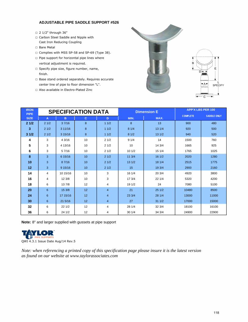
ADJUSTABLE PIPE SADDLE SUPPORT #526
□ 2 1/2" through 36"
□ Carbon Steel Saddle and Nipple with
Cast Iron Reducing Coupling
□ Bare Metal
□ Complies with MSS SP-58 and SP-69 (Type 38).
□ Pipe support for horizontal pipe lines where
vertical adjustment is required.
□ Specify pipe size, figure number, name,
finish.
□ Base stand ordered separately. Requires accurate
center line of pipe to floor dimension "L".
□ Also available in Electro-Plated Zinc
Electro-Plated ZincIRONPIPESIZE A B C D MIN. MAX.2 1/2 2 1/2 3 7/16 8 1 1/2 8 13 900 480
3 2 1/2 3 11/16 8 1 1/2 8 1/4 13 1/4 920 500
3 1/2 2 1/2 3 15/16 8 1 1/2 8 1/2 13 1/2 940 520
4 3 4 3/16 10 2 1/2 9 1/4 14 1500 760
5 3 4 13/16 10 2 1/2 10 14 3/4 1665 925
6 3 5 7/16 10 2 1/2 10 1/2 15 1/4 1765 1025
8 3 6 15/16 10 2 1/2 11 3/4 16 1/2 2020 1280
10 3 8 7/16 10 2 1/2 13 1/2 18 1/4 2515 1775
12 3 9 15/16 10 2 1/2 15 19 3/4 2900 2160
14 4 10 15/16 10 3 16 1/4 20 3/4 4920 3800
16 4 12 3/8 10 3 17 3/4 22 1/4 5320 4200
18 6 13 7/8 12 4 19 1/2 24 7080 5100
20 6 15 3/8 12 4 21 25 1/2 10480 8500
24 6 17 15/16 12 4 23 3/4 28 1/4 13000 11000
30 6 21 5/16 12 4 27 31 1/2 17000 15000
32 6 22 1/2 12 4 28 1/4 32 3/4 18100 16100
36 6 24 1/2 12 4 30 1/4 34 3/4 24900 22900
Note: 8" and larger supplied with gussets at pipe support
QWI 4.3.1 Issue Date Aug/14 Rev.5
Note: when referencing a printed copy of this specification page please insure it is the latest version as found on our website at www.taylorassociates.com
SPECIFICATION DATA APP'X LBS PER 100Dimension ECOMPLETE SADDLE ONLY
118
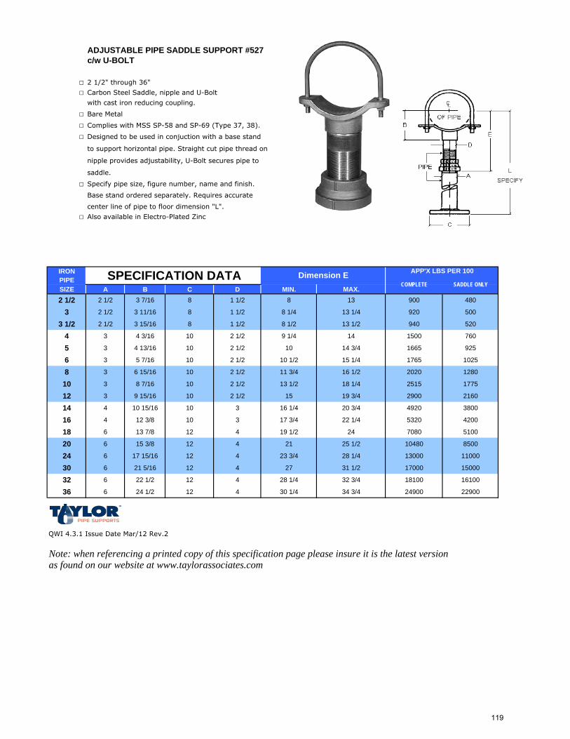
ADJUSTABLE PIPE SADDLE SUPPORT #527c/w U-BOLT
□ 2 1/2" through 36"
□ Carbon Steel Saddle, nipple and U-Bolt
with cast iron reducing coupling.
□ Bare Metal
□ Complies with MSS SP-58 and SP-69 (Type 37, 38).
□ Designed to be used in conjuction with a base stand
to support horizontal pipe. Straight cut pipe thread on
nipple provides adjustability, U-Bolt secures pipe to
saddle.
□ Specify pipe size, figure number, name and finish.
Base stand ordered separately. Requires accurate
center line of pipe to floor dimension "L".
□ Also available in Electro-Plated Zinc
IRONPIPESIZE A B C D MIN. MAX.2 1/2 2 1/2 3 7/16 8 1 1/2 8 13 900 480
3 2 1/2 3 11/16 8 1 1/2 8 1/4 13 1/4 920 500
3 1/2 2 1/2 3 15/16 8 1 1/2 8 1/2 13 1/2 940 520
4 3 4 3/16 10 2 1/2 9 1/4 14 1500 760
5 3 4 13/16 10 2 1/2 10 14 3/4 1665 925
6 3 5 7/16 10 2 1/2 10 1/2 15 1/4 1765 1025
8 3 6 15/16 10 2 1/2 11 3/4 16 1/2 2020 1280
10 3 8 7/16 10 2 1/2 13 1/2 18 1/4 2515 1775
12 3 9 15/16 10 2 1/2 15 19 3/4 2900 2160
14 4 10 15/16 10 3 16 1/4 20 3/4 4920 3800
16 4 12 3/8 10 3 17 3/4 22 1/4 5320 4200
18 6 13 7/8 12 4 19 1/2 24 7080 5100
20 6 15 3/8 12 4 21 25 1/2 10480 8500
24 6 17 15/16 12 4 23 3/4 28 1/4 13000 11000
30 6 21 5/16 12 4 27 31 1/2 17000 15000
32 6 22 1/2 12 4 28 1/4 32 3/4 18100 16100
36 6 24 1/2 12 4 30 1/4 34 3/4 24900 22900
QWI 4.3.1 Issue Date Mar/12 Rev.2
Note: when referencing a printed copy of this specification page please insure it is the latest version as found on our website at www.taylorassociates.com
SPECIFICATION DATA APP'X LBS PER 100Dimension ECOMPLETE SADDLE ONLY
119
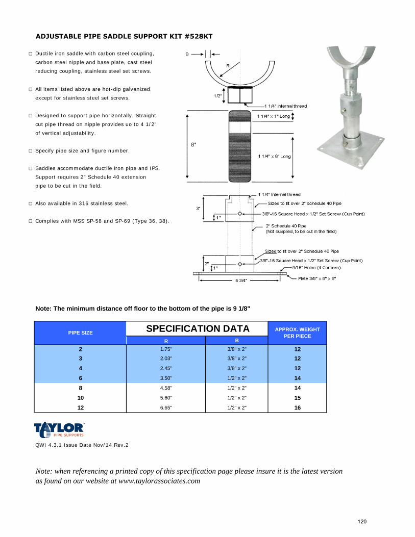
ADJUSTABLE PIPE SADDLE SUPPORT KIT #528KT
□ Ductile iron saddle with carbon steel coupling,
carbon steel nipple and base plate, cast steel
reducing coupling, stainless steel set screws.
□ All items listed above are hot-dip galvanized
except for stainless steel set screws.
□ Designed to support pipe horizontally. Straight
cut pipe thread on nipple provides uo to 4 1/2"
of vertical adjustability.
□ Specify pipe size and figure number.
□ Saddles accommodate ductile iron pipe and IPS.
Support requires 2" Schedule 40 extension
pipe to be cut in the field.
□ Also available in 316 stainless steel.
□ Complies with MSS SP-58 and SP-69 (Type 36, 38).
Note: The minimum distance off floor to the bottom of the pipe is 9 1/8"
R B
2 1.75" 3/8" x 2" 123 2.03" 3/8" x 2" 124 2.45" 3/8" x 2" 126 3.50" 1/2" x 2" 148 4.58" 1/2" x 2" 1410 5.60" 1/2" x 2" 1512 6.65" 1/2" x 2" 16
QWI 4.3.1 Issue Date Nov/14 Rev.2
Note: when referencing a printed copy of this specification page please insure it is the latest version as found on our website at www.taylorassociates.com
APPROX. WEIGHT PER PIECEPIPE SIZE SPECIFICATION DATA
120
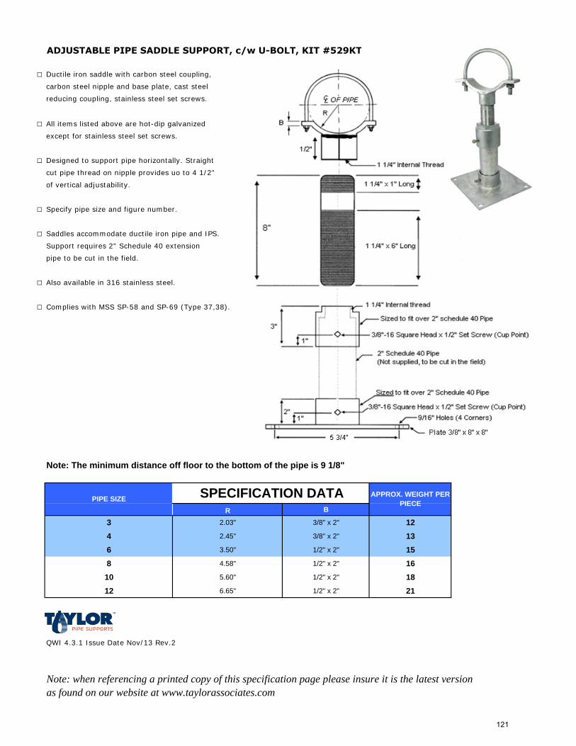
ADJUSTABLE PIPE SADDLE SUPPORT, c/w U-BOLT, KIT #529KT
□ Ductile iron saddle with carbon steel coupling,
carbon steel nipple and base plate, cast steel
reducing coupling, stainless steel set screws.
□ All items listed above are hot-dip galvanized
except for stainless steel set screws.
□ Designed to support pipe horizontally. Straight
cut pipe thread on nipple provides uo to 4 1/2"
of vertical adjustability.
□ Specify pipe size and figure number.
□ Saddles accommodate ductile iron pipe and IPS.
Support requires 2" Schedule 40 extension
pipe to be cut in the field.
□ Also available in 316 stainless steel.
□ Complies with MSS SP-58 and SP-69 (Type 37,38).
Note: The minimum distance off floor to the bottom of the pipe is 9 1/8"
R B
3 2.03" 3/8" x 2" 124 2.45" 3/8" x 2" 136 3.50" 1/2" x 2" 158 4.58" 1/2" x 2" 1610 5.60" 1/2" x 2" 1812 6.65" 1/2" x 2" 21
QWI 4.3.1 Issue Date Nov/13 Rev.2
Note: when referencing a printed copy of this specification page please insure it is the latest version as found on our website at www.taylorassociates.com
APPROX. WEIGHT PER PIECEPIPE SIZE SPECIFICATION DATA
121
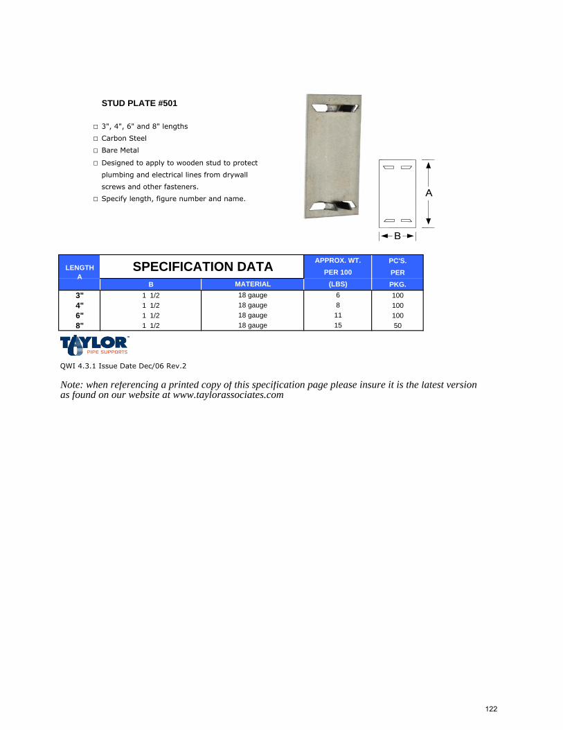
STUD PLATE #501
□ 3", 4", 6" and 8" lengths
□ Carbon Steel
□ Bare Metal
□ Designed to apply to wooden stud to protect
plumbing and electrical lines from drywall
screws and other fasteners.
□ Specify length, figure number and name.
PC'S.PER
B PKG.3" 1 1/2 1004" 1 1/2 1006" 1 1/2 1008" 1 1/2 50
QWI 4.3.1 Issue Date Dec/06 Rev.2
Note: when referencing a printed copy of this specification page please insure it is the latest version as found on our website at www.taylorassociates.com
1115
6
LENGTH A
18 gauge18 gauge
APPROX. WT.PER 100
(LBS)18 gauge
MATERIAL
SPECIFICATION DATA
18 gauge 8
122
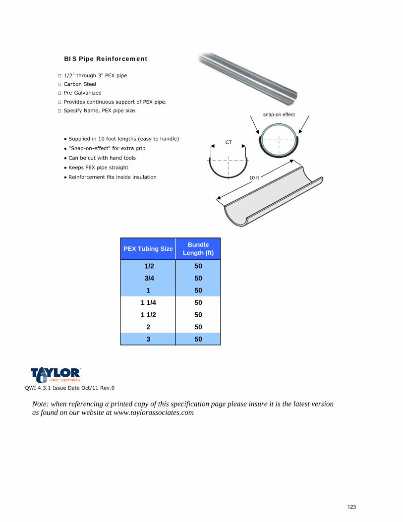
BIS Pipe Reinforcement
□ 1/2" through 3" PEX pipe
□ Carbon Steel
□ Pre-Galvanized
□ Provides continuous support of PEX pipe.
□ Specify Name, PEX pipe size.
● Supplied in 10 foot lengths (easy to handle)
● "Snap-on-effect" for extra grip
● Can be cut with hand tools
● Keeps PEX pipe straight
● Reinforcement fits inside insulation
1/2 50
3/4 50
1 50
1 1/4 50
1 1/2 50
2 50
3 50
QWI 4.3.1 Issue Date Oct/11 Rev.0
Note: when referencing a printed copy of this specification page please insure it is the latest version as found on our website at www.taylorassociates.com
PEX Tubing Size Bundle Length (ft)
snap-on effect
10 ft
CT
123
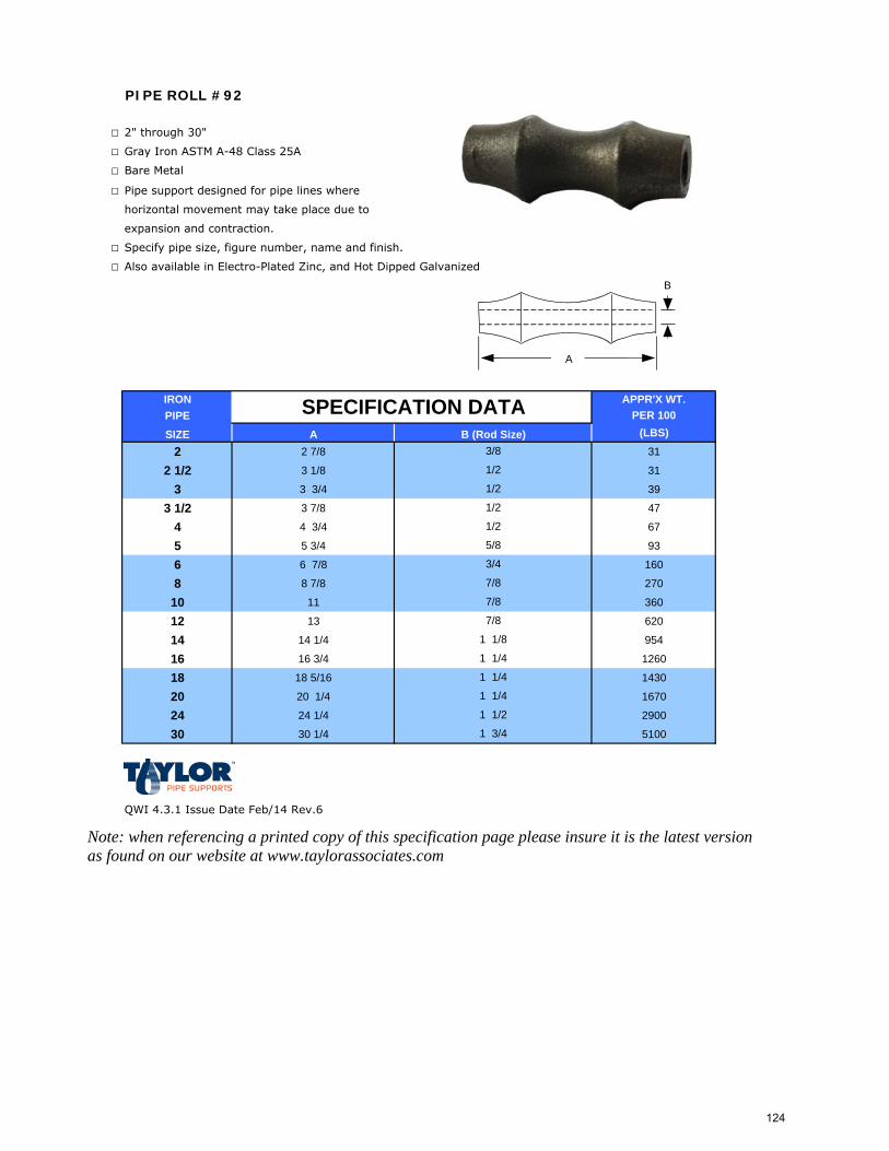
PIPE ROLL #92
□ 2" through 30"
□ Gray Iron ASTM A-48 Class 25A
□ Bare Metal
□ Pipe support designed for pipe lines where
horizontal movement may take place due to
expansion and contraction.
□ Specify pipe size, figure number, name and finish.
□ Also available in Electro-Plated Zinc, and Hot Dipped Galvanized
IRON APPR'X WT.PIPE PER 100
SIZE A (LBS)
2 2 7/8 31
2 1/2 3 1/8 31
3 3 3/4 39
3 1/2 3 7/8 47
4 4 3/4 67
5 5 3/4 93
6 6 7/8 160
8 8 7/8 270
10 11 360
12 13 620
14 14 1/4 954
16 16 3/4 1260
18 18 5/16 1430
20 20 1/4 1670
24 24 1/4 2900
30 30 1/4 5100
QWI 4.3.1 Issue Date Feb/14 Rev.6
Note: when referencing a printed copy of this specification page please insure it is the latest version as found on our website at www.taylorassociates.com
1/2
1/2
1/2
1/2
1 1/4
5/8
1 1/4
1 1/4
1 1/8
1 1/2
1 3/4
SPECIFICATION DATAB (Rod Size)
3/4
3/8
7/8
7/8
7/8
A
B
124
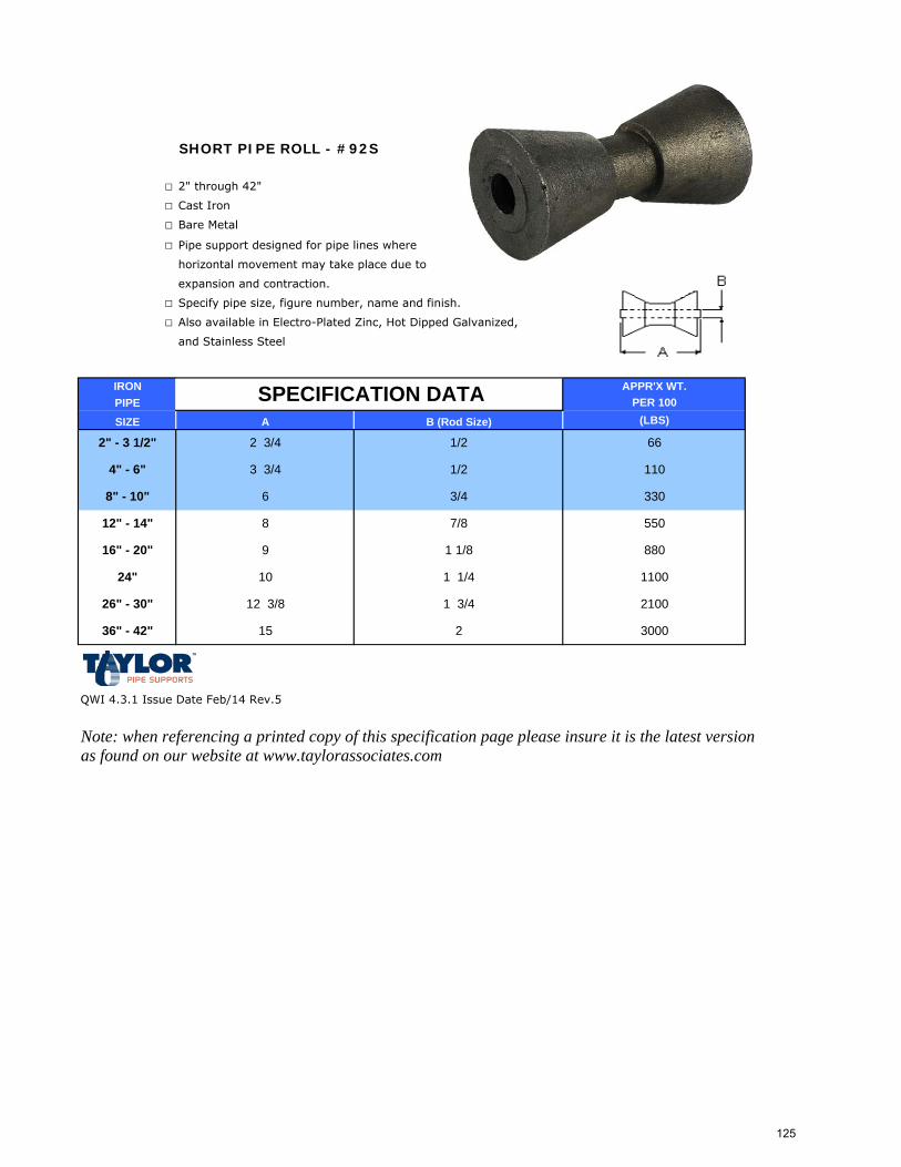
SHORT PIPE ROLL - #92S
□ 2" through 42"
□ Cast Iron
□ Bare Metal
□ Pipe support designed for pipe lines where
horizontal movement may take place due to
expansion and contraction.
□ Specify pipe size, figure number, name and finish.
□ Also available in Electro-Plated Zinc, Hot Dipped Galvanized,
and Stainless Steel
IRON APPR'X WT.PIPE PER 100
SIZE A (LBS)
QWI 4.3.1 Issue Date Feb/14 Rev.5
Note: when referencing a printed copy of this specification page please insure it is the latest version as found on our website at www.taylorassociates.com
36" - 42" 15 2 3000
26" - 30" 12 3/8 1 3/4 2100
24" 10 1 1/4 1100
SPECIFICATION DATA
9
8
6
B (Rod Size)
1/2
3 3/4 1/2
2 3/4
1 1/8
2" - 3 1/2"
12" - 14"
16" - 20"
4" - 6"
7/8
8" - 10" 3/4
880
66
110
330
550
125
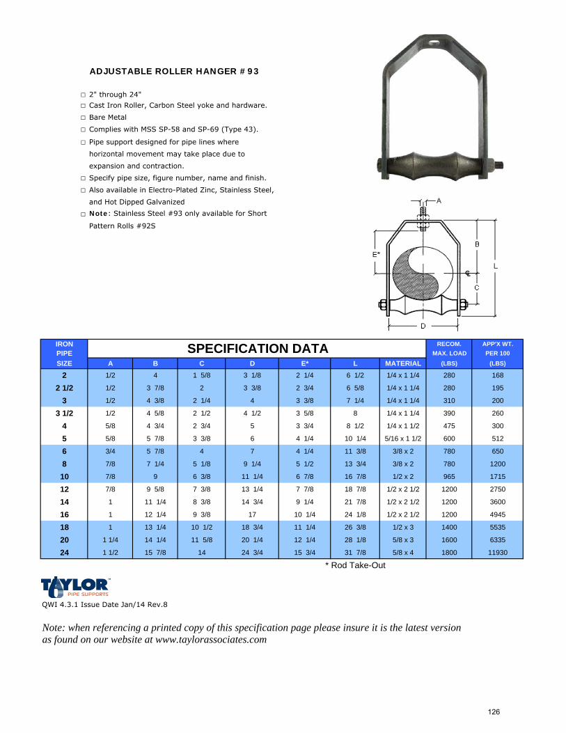
ADJUSTABLE ROLLER HANGER #93
□ 2" through 24"
□ Cast Iron Roller, Carbon Steel yoke and hardware.
□ Bare Metal
□ Complies with MSS SP-58 and SP-69 (Type 43).
□ Pipe support designed for pipe lines where
horizontal movement may take place due to
expansion and contraction.
□ Specify pipe size, figure number, name and finish.
□ Also available in Electro-Plated Zinc, Stainless Steel,
and Hot Dipped Galvanized
□ Note: Stainless Steel #93 only available for Short
Pattern Rolls #92S
IRON RECOM. APP'X WT.PIPE MAX. LOAD PER 100SIZE A B C D E* L MATERIAL (LBS) (LBS)
2 1/2 4 1 5/8 3 1/8 2 1/4 6 1/2 1/4 x 1 1/4 280 168
2 1/2 1/2 3 7/8 2 3 3/8 2 3/4 6 5/8 1/4 x 1 1/4 280 195
3 1/2 4 3/8 2 1/4 4 3 3/8 7 1/4 1/4 x 1 1/4 310 200
3 1/2 1/2 4 5/8 2 1/2 4 1/2 3 5/8 8 1/4 x 1 1/4 390 260
4 5/8 4 3/4 2 3/4 5 3 3/4 8 1/2 1/4 x 1 1/2 475 300
5 5/8 5 7/8 3 3/8 6 4 1/4 10 1/4 5/16 x 1 1/2 600 512
6 3/4 5 7/8 4 7 4 1/4 11 3/8 3/8 x 2 780 650
8 7/8 7 1/4 5 1/8 9 1/4 5 1/2 13 3/4 3/8 x 2 780 1200
10 7/8 9 6 3/8 11 1/4 6 7/8 16 7/8 1/2 x 2 965 1715
12 7/8 9 5/8 7 3/8 13 1/4 7 7/8 18 7/8 1/2 x 2 1/2 1200 2750
14 1 11 1/4 8 3/8 14 3/4 9 1/4 21 7/8 1/2 x 2 1/2 1200 3600
16 1 12 1/4 9 3/8 17 10 1/4 24 1/8 1/2 x 2 1/2 1200 4945
18 1 13 1/4 10 1/2 18 3/4 11 1/4 26 3/8 1/2 x 3 1400 5535
20 1 1/4 14 1/4 11 5/8 20 1/4 12 1/4 28 1/8 5/8 x 3 1600 6335
24 1 1/2 15 7/8 14 24 3/4 15 3/4 31 7/8 5/8 x 4 1800 11930
* Rod Take-Out
QWI 4.3.1 Issue Date Jan/14 Rev.8
Note: when referencing a printed copy of this specification page please insure it is the latest version as found on our website at www.taylorassociates.com
SPECIFICATION DATA
126
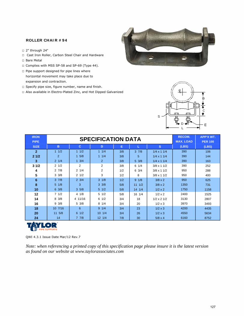
ROLLER CHAIR #94
□ 2" through 24"
□ Cast Iron Roller, Carbon Steel Chair and Hardware
□ Bare Metal
□ Complies with MSS SP-58 and SP-69 (Type 44).
□ Pipe support designed for pipe lines where
horizontal movement may take place due to
expansion and contraction.
□ Specify pipe size, figure number, name and finish.
□ Also available in Electro-Plated Zinc, and Hot Dipped Galvanized
IRON APP'X WT.PIPE PER 100SIZE E L S (LBS)
2 3/8 3 7/8 1/4 x 1 1/4 1062 1/2 3/8 5 1/4 x 1 1/4 144
3 3/8 5 3/8 1/4 x 1 1/4 1633 1/2 3/8 6 1/4 3/8 x 1 1/2 252
4 1/2 6 3/4 3/8 x 1 1/2 2885 1/2 8 3/8 x 1 1/2 4006 1/2 9 1/8 3/8 x 2 6258 5/8 11 1/2 3/8 x 2 731
10 5/8 14 1/4 1/2 x 2 115812 5/8 16 1/4 1/2 x 2 152514 3/4 18 1/2 x 2 1/2 280716 3/4 20 1/2 x 3 349318 3/4 23 1/2 x 3 443520 3/4 26 1/2 x 3 563424 7/8 30 5/8 x 4 8752
QWI 4.3.1 Issue Date Mar/12 Rev.7
Note: when referencing a printed copy of this specification page please insure it is the latest version as found on our website at www.taylorassociates.com
2400
10 1/4
39708 1/49 1/4 4200
455011 5/8 6 1/214
9503 3/8 13505 1/2 1750
31305 1/2
9 3/8 5 3/810 7/16 6
7 1/2 4 1/8
2 3/4
6 3/8 3 5/85 1/8 33 7/8
32
RECOM.MAX. LOAD
(LBS)D
SPECIFICATION DATAB C
390390
1 1/2
1 3/4
2 1/4
1 1/41 1/4
2
390
8 3/8 4 11/16 6 1/2
1 1/2
2 1/4
2 7/83 3/8
2 1 5/8
2 1/2
6160
2 1/2 2 2 390
7 7/8 12 1/4
950950
3 1/8
127
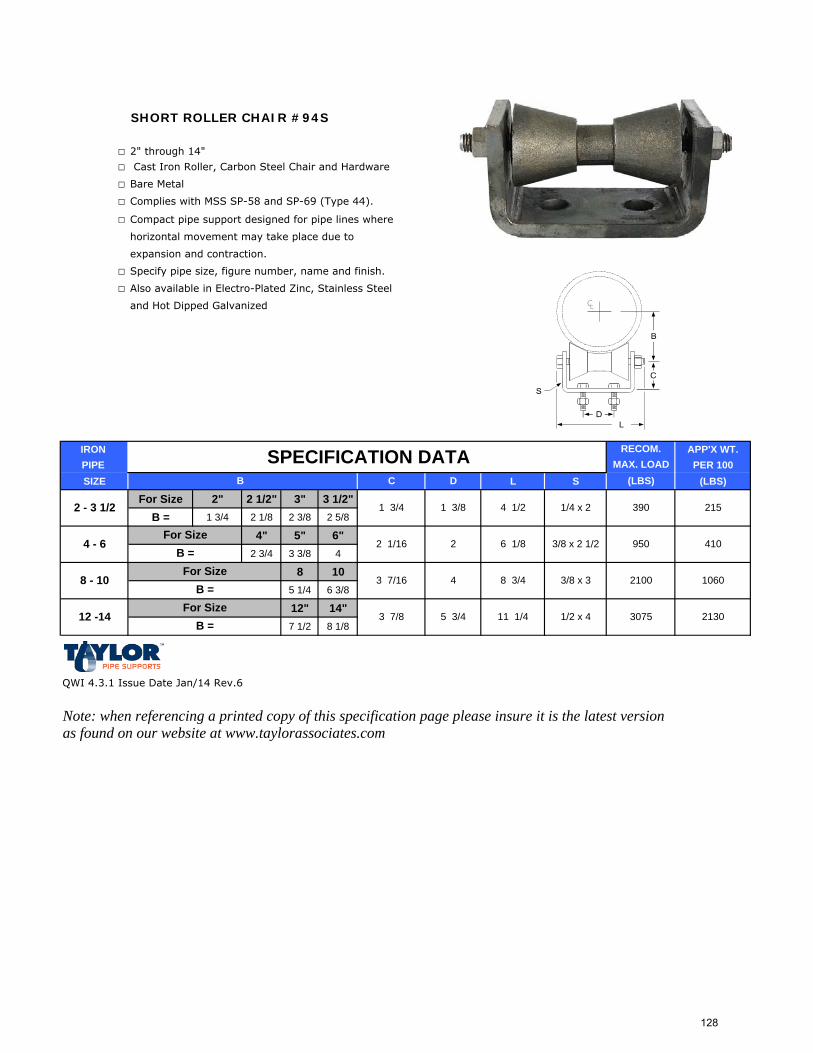
SHORT ROLLER CHAIR #94S
□ 2" through 14"
□ Cast Iron Roller, Carbon Steel Chair and Hardware
□ Bare Metal
□ Complies with MSS SP-58 and SP-69 (Type 44).
□ Compact pipe support designed for pipe lines where
horizontal movement may take place due to
expansion and contraction.
□ Specify pipe size, figure number, name and finish.
□ Also available in Electro-Plated Zinc, Stainless Steel
and Hot Dipped Galvanized
IRON APP'X WT.PIPE PER 100SIZE L S (LBS)
For Size 2" 2 1/2" 3" 3 1/2"B = 1 3/4 2 1/8 2 3/8 2 5/8
4" 5" 6"2 3/4 3 3/8 4
8 105 1/4 6 3/8
12" 14"7 1/2 8 1/8
QWI 4.3.1 Issue Date Jan/14 Rev.6
Note: when referencing a printed copy of this specification page please insure it is the latest version as found on our website at www.taylorassociates.com
2130
B =
B =
B =
For Size
For Size1/2 x 4 307512 -14
2 1/16 2 6 1/8
3 7/16 4 8 3/4
3 7/8 5 3/4 11 1/4
215
B
SPECIFICATION DATA
8 - 10
3/8 x 2 1/2 950 410
3/8 x 3 2100 1060
1 3/8 4 1/2 1/4 x 2 3902 - 3 1/2 1 3/4
4 - 6For Size
RECOM.MAX. LOAD
(LBS)DC
128
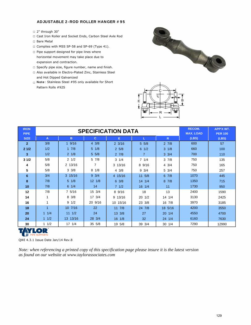
ADJUSTABLE 2-ROD ROLLER HANGER #95
□ 2" through 30"
□ Cast Iron Roller and Socket Ends, Carbon Steel Axle Rod
□ Bare Metal
□ Complies with MSS SP-58 and SP-69 (Type 41).
□ Pipe support designed for pipe lines where
horizontal movement may take place due to
expansion and contraction.
□ Specify pipe size, figure number, name and finish.
□ Also available in Electro-Plated Zinc, Stainless Steel
and Hot Dipped Galvanized
□ Note: Stainless Steel #95 only available for Short
Pattern Rolls #92S
IRON APP'X WT.PIPE PER 100SIZE E L R (LBS)
2 2 3/16 5 5/8 2 7/8 572 1/2 2 5/8 6 1/2 3 1/8 100
3 2 7/8 7 3 3/4 1103 1/2 3 1/4 7 1/4 3 7/8 135
4 3 13/16 8 9/16 4 3/4 1655 4 3/8 9 3/4 5 3/4 2576 4 15/16 11 5/8 6 7/8 4458 6 3/8 14 1/4 8 7/8 715
10 7 1/2 16 1/4 11 95012 8 9/16 18 13 159014 9 13/16 20 1/2 14 1/4 242516 10 15/16 23 3/8 16 7/8 318518 11 7/8 24 7/8 18 5/16 355020 13 3/8 27 20 1/4 470024 16 1/8 32 24 1/4 763030 19 5/8 39 3/4 30 1/4 12990
QWI 4.3.1 Issue Date Jan/14 Rev.8
Note: when referencing a printed copy of this specification page please insure it is the latest version as found on our website at www.taylorassociates.com
6604 3/85 1/8
3/8 1 9/16 600
3 3/8
1/2 1 7/81/2
5/85/8
5/8 2 1/22 1/8
A B
SPECIFICATION DATA
2 13/16
5 5/85 7/8
7
RECOM.MAX. LOAD
(LBS)C
7/8 7 5/16
3 15/16
7/8 6 1/47/8 5 1/83/4
1 9 1/21 8 3/8
45504200221 10 7/16
13 13/161 1/4 11 1/2 24
750
9 3/4 1070
1 1/2 17 1/4 35 5/8616028 3/47290
1 1/2
20 9/1631303970
750
700
17 3/4
1412 1/8
15 3/4 240017301350
8 1/8 750
129
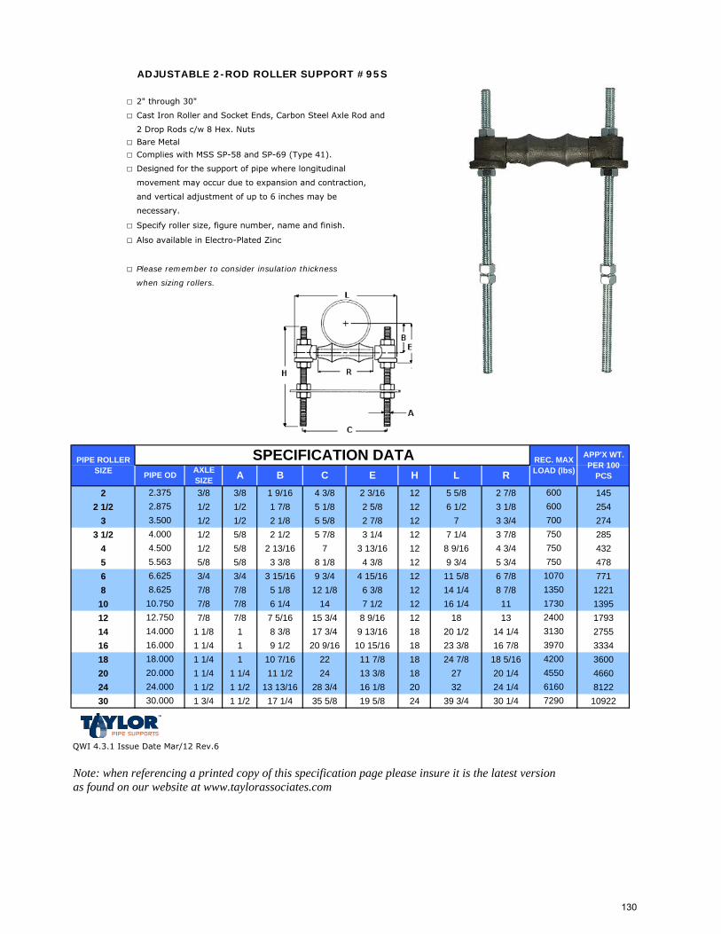
ADJUSTABLE 2-ROD ROLLER SUPPORT #95S
□ 2" through 30"
□ Cast Iron Roller and Socket Ends, Carbon Steel Axle Rod and
2 Drop Rods c/w 8 Hex. Nuts
□ Bare Metal
□ Complies with MSS SP-58 and SP-69 (Type 41).
□ Designed for the support of pipe where longitudinal
movement may occur due to expansion and contraction,
and vertical adjustment of up to 6 inches may be
necessary.
□ Specify roller size, figure number, name and finish.
□ Also available in Electro-Plated Zinc
□ Please remember to consider insulation thickness
when sizing rollers.
2 3/8 3/8 1 9/16 4 3/8 2 3/16 12 5 5/8 2 7/8 1452 1/2 1/2 1/2 1 7/8 5 1/8 2 5/8 12 6 1/2 3 1/8 254
3 1/2 1/2 2 1/8 5 5/8 2 7/8 12 7 3 3/4 2743 1/2 1/2 5/8 2 1/2 5 7/8 3 1/4 12 7 1/4 3 7/8 285
4 1/2 5/8 2 13/16 7 3 13/16 12 8 9/16 4 3/4 4325 5/8 5/8 3 3/8 8 1/8 4 3/8 12 9 3/4 5 3/4 4786 3/4 3/4 3 15/16 9 3/4 4 15/16 12 11 5/8 6 7/8 7718 7/8 7/8 5 1/8 12 1/8 6 3/8 12 14 1/4 8 7/8 1221
10 7/8 7/8 6 1/4 14 7 1/2 12 16 1/4 11 139512 7/8 7/8 7 5/16 15 3/4 8 9/16 12 18 13 179314 1 1/8 1 8 3/8 17 3/4 9 13/16 18 20 1/2 14 1/4 275516 1 1/4 1 9 1/2 20 9/16 10 15/16 18 23 3/8 16 7/8 333418 1 1/4 1 10 7/16 22 11 7/8 18 24 7/8 18 5/16 360020 1 1/4 1 1/4 11 1/2 24 13 3/8 18 27 20 1/4 466024 1 1/2 1 1/2 13 13/16 28 3/4 16 1/8 20 32 24 1/4 812230 1 3/4 1 1/2 17 1/4 35 5/8 19 5/8 24 39 3/4 30 1/4 10922
QWI 4.3.1 Issue Date Mar/12 Rev.6
Note: when referencing a printed copy of this specification page please insure it is the latest version as found on our website at www.taylorassociates.com
4.5004.000
H L
2.875
PIPE OD AXLE SIZE A
3.500
R2.375
APP'X WT. PER 100
PCS
PIPE ROLLER SIZE B C
2400
3970
750
E600
1730
700
REC. MAX LOAD (lbs)
600
SPECIFICATION DATA
750750
10701350
420016.00014.000
72906160
30.000
3130
455024.00020.00018.000
5.563
10.7508.625
12.750
6.625
130
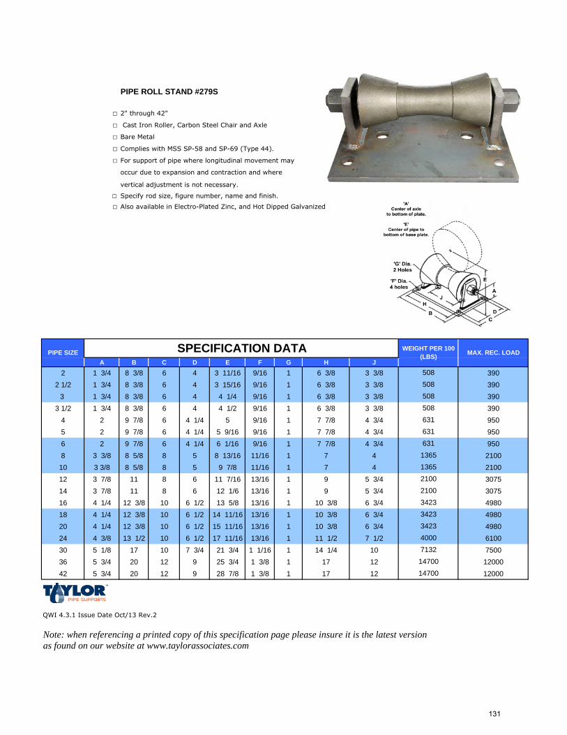
PIPE ROLL STAND #279S
□ 2" through 42"
□ Cast Iron Roller, Carbon Steel Chair and Axle
□ Bare Metal
□ Complies with MSS SP-58 and SP-69 (Type 44).
□ For support of pipe where longitudinal movement may
occur due to expansion and contraction and where
vertical adjustment is not necessary.
□ Specify rod size, figure number, name and finish.
□ Also available in Electro-Plated Zinc, and Hot Dipped Galvanized
A B C D E F G H J2 1 3/4 8 3/8 6 4 3 11/16 9/16 1 6 3/8 3 3/8 390
2 1/2 1 3/4 8 3/8 6 4 3 15/16 9/16 1 6 3/8 3 3/8 3903 1 3/4 8 3/8 6 4 4 1/4 9/16 1 6 3/8 3 3/8 390
3 1/2 1 3/4 8 3/8 6 4 4 1/2 9/16 1 6 3/8 3 3/8 3904 2 9 7/8 6 4 1/4 5 9/16 1 7 7/8 4 3/4 9505 2 9 7/8 6 4 1/4 5 9/16 9/16 1 7 7/8 4 3/4 9506 2 9 7/8 6 4 1/4 6 1/16 9/16 1 7 7/8 4 3/4 9508 3 3/8 8 5/8 8 5 8 13/16 11/16 1 7 4 210010 3 3/8 8 5/8 8 5 9 7/8 11/16 1 7 4 210012 3 7/8 11 8 6 11 7/16 13/16 1 9 5 3/4 307514 3 7/8 11 8 6 12 1/6 13/16 1 9 5 3/4 307516 4 1/4 12 3/8 10 6 1/2 13 5/8 13/16 1 10 3/8 6 3/4 498018 4 1/4 12 3/8 10 6 1/2 14 11/16 13/16 1 10 3/8 6 3/4 498020 4 1/4 12 3/8 10 6 1/2 15 11/16 13/16 1 10 3/8 6 3/4 498024 4 3/8 13 1/2 10 6 1/2 17 11/16 13/16 1 11 1/2 7 1/2 610030 5 1/8 17 10 7 3/4 21 3/4 1 1/16 1 14 1/4 10 750036 5 3/4 20 12 9 25 3/4 1 3/8 1 17 12 1200042 5 3/4 20 12 9 28 7/8 1 3/8 1 17 12 12000
QWI 4.3.1 Issue Date Oct/13 Rev.2
Note: when referencing a printed copy of this specification page please insure it is the latest version as found on our website at www.taylorassociates.com
71321470014700
210021003423342334234000
MAX. REC. LOAD
1365
WEIGHT PER 100 (LBS)
508508508508
PIPE SIZE SPECIFICATION DATA
1365
631
631631
131
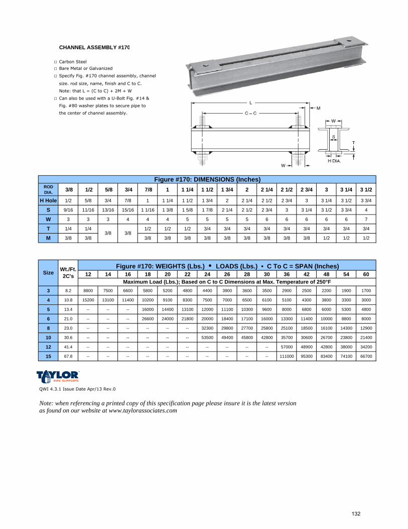
CHANNEL ASSEMBLY #170
□ Carbon Steel
□ Bare Metal or Galvanized
□ Specify Fig. #170 channel assembly, channel
size. rod size, name, finish and C to C.
Note: that L = (C to C) + 2M + W
□ Can also be used with a U-Bolt Fig. #14 &
Fig. #80 washer plates to secure pipe to
the center of channel assembly.
ROD DIA. 3/8 1/2 5/8 3/4 7/8 1 1 1/4 1 1/2 1 3/4 2 2 1/4 2 1/2 2 3/4 3 3 1/4 3 1/2
H Hole 1/2 5/8 3/4 7/8 1 1 1/4 1 1/2 1 3/4 2 2 1/4 2 1/2 2 3/4 3 3 1/4 3 1/2 3 3/4
S 9/16 11/16 13/16 15/16 1 1/16 1 3/8 1 5/8 1 7/8 2 1/4 2 1/2 2 3/4 3 3 1/4 3 1/2 3 3/4 4
W 3 3 3 4 4 4 5 5 5 5 6 6 6 6 6 7
T 1/4 1/4 1/2 1/2 1/2 3/4 3/4 3/4 3/4 3/4 3/4 3/4 3/4 3/4
M 3/8 3/8 3/8 3/8 3/8 3/8 3/8 3/8 3/8 3/8 3/8 1/2 1/2 1/2
12 14 16 18 20 22 24 26 28 30 36 42 48 54 60
3 8.2 8800 7500 6600 5800 5200 4800 4400 3900 3600 3500 2900 2500 2200 1900 1700
4 10.8 15200 13100 11400 10200 9100 8300 7500 7000 6500 6100 5100 4300 3800 3300 3000
5 13.4 -- -- -- 16000 14400 13100 12000 11100 10300 9600 8000 6800 6000 5300 4800
6 21.0 -- -- -- 26600 24000 21800 20000 18400 17100 16000 13300 11400 10000 8800 8000
8 23.0 -- -- -- -- -- -- 32300 29800 27700 25800 25100 18500 16100 14300 12900
10 30.6 -- -- -- -- -- -- 53500 49400 45800 42800 35700 30600 26700 23800 21400
12 41.4 -- -- -- -- -- -- -- -- -- -- 57000 48900 42800 38000 34200
15 67.8 -- -- -- -- -- -- -- -- -- -- 111000 95300 83400 74100 66700
QWI 4.3.1 Issue Date Apr/13 Rev.0
Note: when referencing a printed copy of this specification page please insure it is the latest version as found on our website at www.taylorassociates.com
Figure #170: DIMENSIONS (Inches)
Size Wt./Ft. 2C's
Maximum Load (Lbs.); Based on C to C Dimensions at Max. Temperature of 250°F
Figure #170: WEIGHTS (Lbs.) • LOADS (Lbs.) • C To C = SPAN (Inches)
3/8 3/8
132
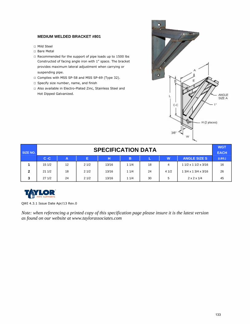
MEDIUM WELDED BRACKET #801
□ Mild Steel
□ Bare Metal
□ Recommended for the support of pipe loads up to 1500 lbs
Constructed of facing angle iron with 1" space. The bracket
provides maximum lateral adjustment when carrying or
suspending pipe.
□ Complies with MSS SP-58 and MSS SP-69 (Type 32).
□ Specify size number, name, and finish
□ Also available in Electro-Plated Zinc, Stainless Steel and
Hot Dipped Galvanized.
WGTEACH
C -C A E H B L W ANGLE SIZE S (LBS.)
1 15 1/2 12 2 1/2 13/16 1 1/4 18 4 1 1/2 x 1 1/2 x 3/16 16
2 21 1/2 18 2 1/2 13/16 1 1/4 24 4 1/2 1 3/4 x 1 3/4 x 3/16 26
3 27 1/2 24 2 1/2 13/16 1 1/4 30 5 2 x 2 x 1/4 45
QWI 4.3.1 Issue Date Apr/13 Rev.0
Note: when referencing a printed copy of this specification page please insure it is the latest version as found on our website at www.taylorassociates.com
SPECIFICATION DATASIZE NO.
133
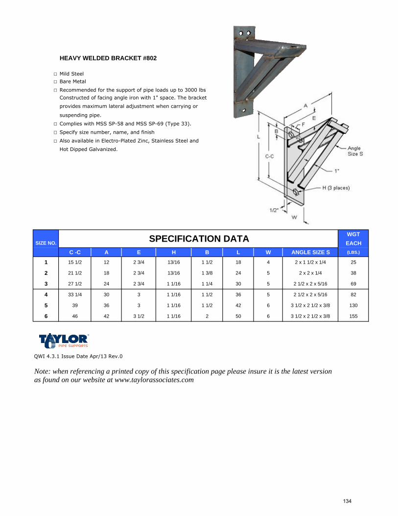
HEAVY WELDED BRACKET #802
□ Mild Steel
□ Bare Metal
□ Recommended for the support of pipe loads up to 3000 lbs
Constructed of facing angle iron with 1" space. The bracket
provides maximum lateral adjustment when carrying or
suspending pipe.
□ Complies with MSS SP-58 and MSS SP-69 (Type 33).
□ Specify size number, name, and finish
□ Also available in Electro-Plated Zinc, Stainless Steel and
Hot Dipped Galvanized.
WGTEACH
C -C A E H B L W ANGLE SIZE S (LBS.)
1 15 1/2 12 2 3/4 13/16 1 1/2 18 4 2 x 1 1/2 x 1/4 25
2 21 1/2 18 2 3/4 13/16 1 3/8 24 5 2 x 2 x 1/4 38
3 27 1/2 24 2 3/4 1 1/16 1 1/4 30 5 2 1/2 x 2 x 5/16 69
4 33 1/4 30 3 1 1/16 1 1/2 36 5 2 1/2 x 2 x 5/16 82
5 39 36 3 1 1/16 1 1/2 42 6 3 1/2 x 2 1/2 x 3/8 130
6 46 42 3 1/2 1 1/16 2 50 6 3 1/2 x 2 1/2 x 3/8 155
QWI 4.3.1 Issue Date Apr/13 Rev.0
Note: when referencing a printed copy of this specification page please insure it is the latest version as found on our website at www.taylorassociates.com
SPECIFICATION DATASIZE NO.
134
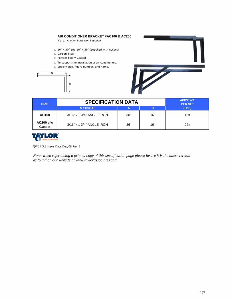
AIR CONDITIONER BRACKET #AC100 & AC200Note: Anchor Bolts Not Supplied
□ 16" x 30" and 16" x 36" (supplied with gusset)
□ Carbon Steel
□ Powder Epoxy Coated
□ To support the installation of air conditioners.
□ Specify size, figure number, and name.
APP'X WT.SIZE PER SET
MATERIAL A B (LBS)
QWI 4.3.1 Issue Date Dec/08 Rev.5
Note: when referencing a printed copy of this specification page please insure it is the latest version as found on our website at www.taylorassociates.com
3/16" x 1 3/4" ANGLE IRONAC200 c/w Gusset 22#
30"
36"
16"
16"
SPECIFICATION DATA
3/16" x 1 3/4" ANGLE IRONAC100 16#
135